Instruction Manual. User Manual. From Software Version 0.78
|
|
|
- Hannah Chambers
- 6 years ago
- Views:
Transcription


1 Instruction Manual User Manual From Software Version 0.78
2 GT-1 Instruction Manual Revision 0.5, Applies from firmware version.78 June, 2017 The GT-1 and this instruction manual are intended for use by experienced professionals with the knowledge and skills to set up, operate, and maintain high-powered, remotely controlled lighting equipment safely and efficiently. Save this manual for future reference. Replacement copies and updates are available for download in electronic format from The information in this manual is subject to change without notice German Light Products GmbH (GLP), Industriestr. 2, Karlsbad, Germany
3 German Light Products GmbH Table of Contents 1 Safety Precautions DANGER! Prevent Hazards that Will Result in Serious Injury or Death WARNING! Prevent Hazards that Could Result in Serious Injury or Death CAUTION! Prevent Hazards that Could Result in Moderate Injury NOTICE! Prevent Damage to Product or other Property Overview of Features Intended Use Lamp Pan and Tilt Color Gobos Dimming and Shutter Effects Focus and Zoom Prisms and Frost Animation Wheel Changing Effect Settings by DMX Display Base and rigging options Preparation for Use Included Items Safe Handling Mounting Securing the Device Connections Start/stop operation Transportation and Storage The Menu Field DMX Channels Normal Mode (23 DMX Channels) Optional Accessories Cleaning and Maintenance Suggested Maintenance Intervals Cleaning Lubrication Head Maintenance GLP Service and Support Technical Specifications Dimensions Instruction Manual 3
4 1 Safety Precautions The GT-1 and this instruction manual are intended for use by experienced professionals with the knowledge and skills to set up, operate, and maintain highpowered, remotely controlled lighting equipment safely and efficiently. These operations require expertise that is not provided in this manual. Read this manual and familiarize yourself with the safety precautions before installing or using the product. The manufacturer will take no responsibility for damages or harm caused by disregard for the information in this manual. Should you have questions about the safe operation of the GT-1, please contact an authorized GLP distributor, a list of which can be found at DANGER! Prevent Hazards that Will Result in Serious Injury or Death Avoid direct exposure to a hot or operating lamp. Discharge lamps operate at high internal pressure and can explode without warning. The extremely hot shards of broken glass from an unshielded lamp will cause serious injury. Looking directly at an unshielded lamp can cause serious eye damage. Direct exposure to UV radiation can cause skin burns. Operate the lamp only with all covers in place. Turn off the lamp and allow to cool for at least 60 minutes before removing any head cover. Wear safety goggles whenever the lamp is exposed. 1.2 WARNING! Prevent Hazards that Could Result in Serious Injury or Death Do not look directly into the beam of light: brief exposure can cause eye injury. Avoid exposing your eyes to direct radiation! Do not view the light output with optical instruments or any device that may concentrate the beam. Risk Group 2 product according to EN Do not illuminate surfaces within 16 M (52.5 ft.) of the fixture. When concentrated in a narrow beam, the light output is powerful enough to cause burns or fire in illuminated objects at near range. Installation shall be performed by qualified personnel only in accordance with local regulations. To prevent falls, suspend the GT-1 with hardware specifically designed and rated for the purpose and a form of backup attachment such as a safety cable. Hot surfaces! Avoid touching lights during the operation. This can cause injuries and/or damage. Avoid placing lighting fixtures in locations where there is risk of accidental contact. Allow fixtures to cool before handling. Connect the fixture only to a grounded (earthed) power supply with overload protection for protection against electric shock. Verify that power cables and connectors are in good condition. Replace a blown fuse with one of the specified rating only. 1.3 CAUTION! Prevent Hazards that Could Result in Moderate Injury Avoid using strobe effects for extended periods. Flashing light, particularly between 4 Instruction Manual
5 German Light Products GmbH 5 and 30 flashes per second, may cause seizures in persons with photosensitive epilepsy. Check local regulations on use of strobe lighting and notify the public in advance when strobe effects are used. If a seizure occurs, stop using strobe effects. Help the person sit in a safe place or lay them on their side with their head supported to prevent it from hitting the floor. Do not use force. Seek emergency medical help if the seizure lasts for more than a few minutes. Do not operate a fixture with damaged, cracked, or missing pieces. All optical components and covers must be in good condition to prevent injury from UV radiation. The lamp contains mercury. Do not attempt to clean or repair damage from a broken lamp. Special safety precautions must be taken. Refer the fixture to an authorized service facility. 1.4 NOTICE! Prevent Damage to Product or other Property Avoid pointing the front of the fixture towards direct sunlight or other strong light sources. The front lens focuses and concentrates light just like a magnifying glass. Direct sunlight and other bright light sources can cause internal damage to the fixture, melting components or starting an internal fire within seconds. Damage can occur whether the fixture is powered on or off. To avoid problems: Never expose the front of a fixture to direct sunlight or any other strong light sources. For outdoor applications during daylight, make sure that the front face of any fixture is shielded or points away from the sun, even when not in use. Avoid pointing other high-powered beam lights directly at the fixture. Ensure that the moving head can rotate through its full range of motion before powering up the fixture, and that fans and air vents are clean and unobstructed. Do not pick up or carry the fixture by the front lens bezel. The LCD display is also fragile. Picking up or supporting the fixture in these spots could result in damage that is not be covered by the warranty. Use only original spare parts. Any structural modification on the system will terminate all warranty claims. Do not exceed 1500 lamp hours. Risk of damage from lamp explosion increases as the lamp approaches its specified usage life. For best performance, replace the lamp after 1000 hours of operation. Clean optical components only as directed. Oils, solvents, and other chemicals commonly used for cleaning can damage the lens coatings and surfaces. Instruction Manual 5
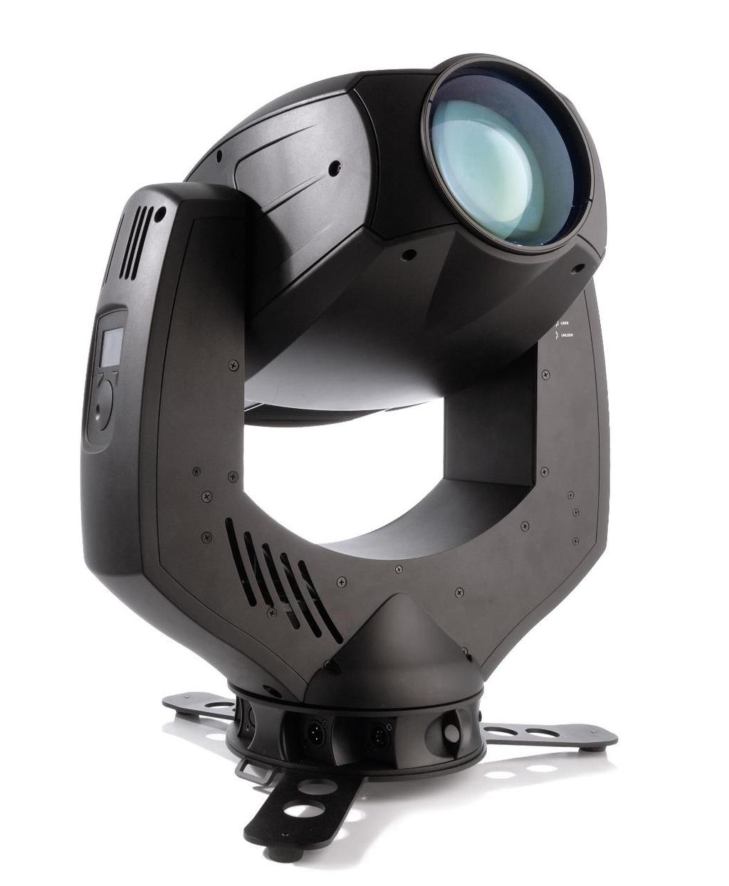
6 2 Overview of Features 2.1 Intended Use The GT-1 is for permanent or temporary indoor use in venues where the distance to illuminated surfaces is at least 16 M (52.5 ft.). It may be used outdoors if it is protected from moisture and precautions are taken to prevent damage from direct sunlight. It may be placed upright on a level surface or suspended from a suitable structure as described in Section 3.3. It is not suitable for household use, wherever unattended children have access to it, for permanent outdoor installation, or in areas where the distance from the fixture to illuminated surfaces is less than specified. The GT-1 shall be installed, operated, and maintained only by persons with the training, knowledge and skills to do safely and efficiently. 2.2 Lamp The GT-1 s OSRAM SIRIUS HRI 440W lamp is a compact reflector lamp with a very short arc and high light output optimized to create sparkling effects. The lamp was developed specifically for moving heads to perform in any position. It outputs 22,000 lumens at a color temperature of 7300K with a color rendering index of 80. The lamp s average rated life is 1500 hours. It should be replaced every 1000 hours to minimize the risk of lamp explosion. 2.3 Pan and Tilt The GT-1 pans through 640 and tilts through 262 with coarse and fine control channels and self-correcting position feedback. Position feedback can be disabled and control of pan and tilt can be reversed from the control panel or by DMX. 2.4 Color The GT-1 provides CMY color mixing with progressively saturated cyan, magenta, and yellow wheels. The Old CMY curve setting is for use on prototype fixtures that had different wheels. 6 Instruction Manual
7 German Light Products GmbH A separate color wheel supplements the color mixing system with 11 color filters, including four color correction filters and a light frost filter. The wheel rotates in fixed color steps, scrolls continuously for split color effects, and rotates clockwise and counterclockwise with variable speed Figure 2-1: Color and fixed gobo wheels 2.5 Gobos Fixed Gobos Gobo wheel 2 is an aluminum wheel with 19 patterns, including five iris gobos. The wheel steps to fixed positions and rotates continuously clockwise and counterclockwise with variable speed. Rotating Gobos Gobo wheel 1 provides eight user-replaceable rotating glass gobos that can be rotated to indexed positions or continuously with coarse and fine control channels. Custom gobos shall be 22.9 mm in diameter with a maximum image diameter of 13 mm. They may be manufactured in 0.8 mm 5052 aluminum or 1 mm litho/dichro coated quartz. See page 22 for the gobo replacement procedure Figure 2-2: Stock rotating gobos Instruction Manual 7
8 2.6 Dimming and Shutter Effects The GT-1 features a combined dimmer and shutter system that provides full range dimming along with flashing pulse and strobe effects up to 10 flashes per second. Two dimming curves are available: linear and extra soft. The mode can be selected from the control panel or by DMX. 2.7 Focus and Zoom The GT-1 has a 3-element optical train with motorized front lens, zoom lens, and focus lens. The fixture s two-stage zoom system narrows the focused beam from 56 down to 3.5 by moving the zoom lens from front to back. It narrows the beam to 2.5 in Beam Mode by moving the front lens forward. The beam may be narrowed further by inserting iris gobos. When inserted, the frost filter and prisms are in the path of the zoom lens. When either of these effects are applied, zoom is not continuous. Zoom channel values from 82 to 177 are disabled when frost is applied. Zoom channel values from 107 to 208 are disabled when a prism is inserted. When taking zoom past these levels in either direction, the frost and prism effects are automatically removed momentarily. 2.8 Prisms and Frost The GT-1 provides three rotating prisms: a 3-facet, an 8-facet, and a 4-facet linear. The prisms can be rotated to indexed positions or continuously at variable speed. Inserting or removing a prism with zoom at a DMX level from will cause a small change in the zoom lens position. The GT-1 has a split-flag variable frost filter that provides a wide angle wash effect. Inserting or removing frost at zoom levels from will cause a small change in the zoom lens position. 2.9 Animation Wheel The GT-1 s animation wheel can be inserted gradually to positions that, when combined with variable speed clockwise and counterclockwise rotation, give the appearance of vertical, diagonal, or horizontal movement in two directions. 8 Instruction Manual
9 German Light Products GmbH 2.10 Changing Effect Settings by DMX Figure 2-3: Animation wheel The Control Channel (23 in Normal DMX Mode) provides the ability to change fixture settings, turn the lamp on/off, and perform a fixture reset from the control desk. To send a send a Control Channel command, start from level 0 and hold the command for three seconds Display The illuminated graphic LCD display with touch wheel control and self-charging battery allows you to change fixture settings quickly and intuitively under any conditions, even when the power is off. See Chapter 4 for settings, readouts, and related information Base and rigging options The base provides Camlock attachment points for easy fastening of the included floor stand, omega clamp attachment brackets, and other rigging accessories. It also provides 2 M10 threaded sockets for direct fastening of half-coupler clamps. Two countersunk bolts are provided for clamp attachment. Instruction Manual 9
10 3 Preparation for Use Installation shall be performed by qualified personnel only, in accordance with applicable regulations such as BGV C1 and DIN VDE Included Items The GT-1 package includes a floor stand, a power cord with PowerCON connector, and two M10 x 25 countersunk bolts for fastening half-couplers. 3.2 Safe Handling describe methods of lifting and omega clamps with handles 3.3 Mounting The GT-1 may be rigged in any orientation or placed on a level surface. When installing, keep the lighting head at least 0.5 m (20 in.) from flammable materials including curtains and stage scenery. Figure 3-1: Mounting Options Accessories are available to mount the GT-1 in various positions. These fasten to the connectors on the base to ensure safe and stable installation. 10 Instruction Manual
11 German Light Products GmbH Mounting Upright on a Level Surface For upright installation on a level surface, fasten the floor stand shipped with the fixture to the base. The floor stand mounts to the base with two Camlock quarter-turn pins. Line up and insert the pins into the base and turn 90 clockwise to lock. Do the opposite to release them. There are eyelets on both sides of the floor stand that a ratchet strap can be passed through for additional bracing if necessary. Camlock pin Strap eyelet Camlock M10 Gewinde thread Camlock Figure 3-2 Upright Mounting Details Head Down Mounting To hang the GT-1 with the head down, mount two omega brackets to the base and fasten a suitable rigging clamp to each omega bracket. The brackets mount to the base with two Camlock quarter-turn pins. Line up and insert the pins into the base and turn 90 clockwise to lock. Do the opposite to release them. Alternatively, two suitable clamps may be bolted directly to the base with suitable 12 mm diameter hardware. Two countersunk 12 mm screws are shipped with the fixture for this purpose. Notice! The threaded holes are 19 mm (3/4 ) deep. Use fasteners that reach at least 11 mm (7/16 in.) and no more than 19 mm (3/4 in.) into the threaded hole. Secure as directed in section 3.4. Instruction Manual 11


12 Sideways Mounting Figure 3-3: Omega Clamp Detail Notice! Never use the head-down mounting technique for sideways installation, as the base can be damaged and secure installation cannot be assured. To hang the GT-1 sideways, fasten a dedicated mounting bar, available from GLP as an accessory, to the base. Fasten two suitable half-coupler rigging clamps to the mounting bar to hang the fixture. This technique is necessary to cope with the additional torque when the fixture is mounted sideways. The mounting bar fastens to the base with Camlock quarter-turn pins. Line up and insert all four pins into the base and turn 90 clockwise to lock. Do the opposite to release them. Figure 3-4: Sideways Mounting 3.4 Securing the Device Warning! Use a secondary attachment (safety wire) that can hold at least 10 times the weight of the fixture whenever hanging the fixture. Two eyes are provided on the base for this purpose. Pass the safety wire through the eye in the base and through or around the truss or supporting structure. 12 Instruction Manual


13 German Light Products GmbH 3.5 Connections Figure 3-5: GT-1 connection sockets Power The AC supply shall provide earth ground connection and overload protection. Before applying power, verify that the head is unlocked and can move freely. The GT-1 provides a 3-conductor, 20 A Neutrik powercon socket for connection to AC power. The autosensing power supply accepts V, 50/60 Hz AC power. Do not connect the fixture to any other voltage or an external dimmer. To prevent arcing at the power connection, turn the power switch off before connecting or disconnecting a live power cable. Verify that the head is unlocked before turning the fixture on. The main fuse is located in a holder in the base. WARNING! Always disconnect the fixture from the mains supply before replacing the fuse. Replace only with fuse of the specified type. Control Data The GT-1 provides both 3-pin and 5-pin XLR input/output sockets for connection to a USITT DMX-512 Standard data link. Use only one DMX input and one DMX output. The pin connections are Pin 1 = [Ground] / Pin 2 = [-] / Pin 3 = [+]. Pins 4 & 5 on the 5- pin sockets have no contact. The fixture is ACN ready and provides a Neutrik RJ-45 socket for connection to an ArtNET II compatible Ethernet network. 3.6 Start/stop operation To start or stop operation, toggle the power switch to the I (on) or O (off) position. 3.7 Transportation and Storage The GT-1 should be transported either in a flight case or its original packaging to Instruction Manual 13

 Figure 4-1: Menu display In the example shown in Figure 4-1, the fixture is running software version.")

, run, ok, or err")
14 protect it from damage from shocks during transportation. When not installed, store the fixture in a dry location. 4 The Menu Field The LCD display provides access to user settings, readouts, lamp control, and utilities. From left to right, the top line of the main menu displays: main CPU software version pan, tilt, and zoom modes: N(ormal) or I(inverse) DMX mode dimming mode: L(inear) or E(xtra Soft) Figure 4-1: Menu display In the example shown in Figure 4-1, the fixture is running software version.71; with normal pan, inverted tilt, and normal zoom; Normal 23 channel DMX mode; and linear dimming. When booting up, the panel displays two screens of fixture information including component firmware and hardware versions and fixture and lamp hours before displaying the PCB reset status screen. Figure 4-2: Example of boot sequence and reset displays Following the label for each effect motor, the reset status screen displays either --- (standby), run, ok, or err while the reset is in progress. When completed, the panel displays the main menu. A flashing display indicates loss of DMX. Turn the control dial to scroll menu options. Press the Enter button to select a setting, issue a command, or enter a submenu. Press the Mode button to escape and return to the top of the menu. DMX control is disabled when the menu is active. 14 Instruction Manual
15 German Light Products GmbH Menu Selection Value Remarks DMX Start Address Set the DMX start address Special Set dimming mode* ESOFT - Softer, nonlinear dimming LIN - Linear dimming Show Errors - Display error messages DMX hold* ON/OFF Hold last values if DMX signal drops Test mode ON/OFF Run a test sequence Default* - Return all user settings to default values Temperature main XX Readout temperature on main PCB( C) Temperature base XX Readout temperature in base ( C) Temperature head XX Readout temperature in head ( C) Boot count XX Read number of fixture starts Fixture hours XX Read total fixture hours Lamp strikes XX Read number of lamp starts Lamp hours XX Read number of lamp hours Reset lamp hours - Set hours and strikes counters to 0 Adjust Key Code Enter code to access menu Pan offset Tilt offset Beam lens offset Zoom offset Frost1 offset Frost2 offset Prism Position offset Prism Rotation offset Focus offset RotGobo Pos. offset RotGobo Rot. offset FixGobo offset ColorWheel offset Cyan offset Cyan offset fine Magenta offset Magenta offset fine Yellow offset Yellow offset fine Shutter1 offset Shutter2 offset -99 to 99 Enter position offset values LBAM test mode ON/OFF Initiate test * May be set remotely by DMX Instruction Manual 15
16 Serial Enter user-defined ID number Lamp on * - Switch lamp on Lamp off* - Switch lamp off Old CMY curve* ON/OFF Select dimming curve for early CMY flags Position feedback* ON/OFF Toggle position feedback Reverse pan* ON/OFF Reverse pan control Reverse tilt* ON/OFF Reverse tilt control Reverse zoom* ON/OFF Reverse zoom control Reset pan/tilt only* - Reset pan/tilt movement Reset head only* - Reset effects in head Reset* - Reset everything * May be set remotely by DMX 16 Instruction Manual
17 German Light Products GmbH 5 DMX Channels 5.1 Normal Mode (23 DMX Channels) Channel Function Time & Value Percent DMX 1 Pan, MSB coarse pan (high/8-bit) % Pan, LSB fine pan (low/16-bit) 0-100% Tilt, MSB coarse tilt (high/8-bit) % Tilt, LSB fine tilt (low/16-bit) 0-100% Color Wheel color wheel position and rotation (1) open (2) primary red (3) primary blue (4) CTO 4200 (5) CTO 3200 (6) CTO 5600 (7) half minus green (8) light frost (9) vivid pink (10) cyan (11) medium orange (12) Congo blue color scroll / split colors negative rotation, fast to slow rotation stop positive rotation, slow to fast 0-1% 2% 4% 5% 7% 8% 10% 12% 13% 15% 16% 18% 19-65% 66-82% 83% % Cyan cyan color mixing no cyan to full cyan 0-100% Magenta magenta color mixing no magenta to full magenta 0-100% Yellow yellow color mixing no yellow to full yellow 0-100% Gobo Wheel 1 rotating gobo selection Gobo Indexing / Rotation, MSB Gobo Indexing / Rotation, LSB coarse gobo indexing & rotation fine gobo indexing & rotation 12 Gobo Wheel 2 fixed gobo selection (1) Open (2) Pick Up Sticks (3) Window Grills (4) Dotted Lines (5) Square Outline (6) Fan Flags (7) Linear (8) Speckle (9) Explosion coarse indexing, negative rotation, fast to slow rotation stop positive rotation, slow to fast 0-12% 14-23% 24-33% 35-44% 46-54% 56-65% 66-75% 77-86% % 0-49% 50-74% 75% % fine indexing/rotation speed 0-100% (1) open (2) gobo 01 (3) gobo 02 (4) gobo 03 (5) gobo 04 (6) gobo 05 (7) gobo 06 (8) gobo 07 (9) gobo 08 (10) gobo 09 (11) gobo 10 (12) gobo 11 (13) gobo 12 (14) gobo 13 (15) gobo % 2% 4% 5% 7% 8% 10% 12% 13% 15% 16% 18% 19% 21% 22% Instruction Manual 17
18 12 Gobo Wheel 2 continued 13 Shutter fixed gobo selection shutter and strobe effects (16) gobo 15 (17) gobo 16 (18) gobo 17 (19) gobo 18 (20) gobo 19 negative rotation, fast to slow rotation stop positive rotation, slow to fast closed random pulse, slow to fast fade-in pulse, random slow to fast fade-out pulse, random slow to fast fade-in/out pulse, rnd slow to fast flash, delayed 5 sec. to 1 sec. strobe effect, 1 to 10 Hz shutter open 24% 25% 27% 29% 30% 32-65% 66% % 0-5% 7-18% 19-30% 32-43% 44-55% 56-77% 79-93% % Dimmer dimmer open to closed 0-100% Focus, MSB coarse focus (low/8-bit) near to infinity 0-100% Focus, LSB fine focus (high/16-bit) near to far 0-100% Zoom zoom angle zoom angle, wide to near 0-91% beam mode % Frost insert frost filter full out to full in 0-100% Prism prism selection 20 Prism Rotation prism indexing and rotation open (no prism) 8-facet 3-facet 4-facet linear index negative rotation, fast to slow rotation stop positive rotation, slow to fast 0-25% 26-49% 50-73% % 0-49% 50-74% 75% % Effect Wheel insert effect wheel full out to full in 0-100% rotation stop 0% 0 22 Effect Wheel negative rotation, fast to slow 1-49% effect wheel rotation Rotation rotation stop 50% 128 positive rotation, slow to fast % Control Channel fixture control: set to level 0 before sending command, hold command for 3 seconds enable commands reserved new CMY curve old CMY curve reset head (only) lamp off no function lamp on Esoft dimmer curve linear dimmer curve disable position feedback enable position feedback disable DMX hold enable DMX hold zoom inverse, Off zoom inverse, On tilt inverse, Off tilt inverse, On pan inverse, Off pan inverse, On factory defaults fixture reset 0% 1-68% 69% 71% 72% 74% 76% 77% 79% 80% 82% 83% 85% 87% 88% 90% 91% 93% 94% 96% 97% % Instruction Manual
19 German Light Products GmbH 6 Optional Accessories Describe accessories and how to install Instruction Manual 19
20 7 Cleaning and Maintenance WARNING! Never look directly into the beam of light or into the lamp. An exposed lamp emits hazardous radiation that can cause burns. Brief exposure can cause eye injury. 7.1 Suggested Maintenance Intervals The cleaning schedule depends on the operating environment. The intervals below are suggestions from our experience with typical installations. Adjust as necessary. Maintenance Task Interval How Lamp replacement 1000 hours See page 24. Front lens weekly soft cloth and glass cleaning fluid Metal gobos yearly vacuum cleaner, airbrush, etc. Glass gobos yearly soft cloth and glass cleaning fluid Prism yearly soft cloth and glass cleaning fluid Animation wheel yearly vacuum cleaner, airbrush, etc. Internal lenses yearly soft cloth no glass cleaning fluid Fans and air channel monthly vacuum cleaner, airbrush, etc. Moveable parts yearly suitable lubricant 7.2 Cleaning Never use alcohol or solvents to clean the lens! Never let optical parts come into contact with oil, grease, alcohol or similar solvents. (add consequences) Never touch optical components with bare fingers. Before running the fixture wait until all parts are dry. GT-1 components require occasional cleaning to prevent the buildup of dust, dirt, and smoke fluid residue. Pay special attention to the air vents and front lens. Failure to keep the fixture clean will significantly reduce light output and may cause damage. Regular cleaning will ensure the maximum performance and reliable operation. Under no circumstances should alcohol or solvents be used to clean the fixture or its lenses! 7.3 Lubrication add information on points to lubricate and suitable lubricants, get illustration 20 Instruction Manual
21 German Light Products GmbH 7.4 Head Maintenance A hot discharge lamp can explode and cause severe injury. Turn off the lamp and allow it to cool for 60 minutes before opening the head. Wear safety goggles and gloves. With the exception of installing gobos, any operation that requires removal of a cover shall be performed by a professional service technician with the tools, skills, and personal protective equipment to maintain high-powered lighting equipment safely and efficiently Figure 7-1: Head cover removal Removing head covers To remove the top head shell, orient the head as shown above with the front lens to the right and the yoke arm with the GT-1 logo facing you. To remove the bottom head shell, orient the head with the front lens to the left. Remove the head shells as follows: Release the four shell retaining pins by turning them a quarter turn Instruction Manual 21


22 counterclockwise with a slotted screwdriver. Lift the head shell up from the front. Release the shell safety cable. Lift the head shell further to free it from the rear cover and remove. Installation is the reverse. Start at the back and align the opening in the head shell with the air vent to get started. To remove the rear head cover, simply remove the screw in each corner. Gobo Change, Single Gobo Figure 7-2: Back cover removal Note: Wear gloves when handling gobos. If replacing multiple gobos, it may be easier to remove the module. To replace a single gobo, proceed as follows: Remove the top head shell as described above. Bring the desired gobo slot to the access port. Turn the holder so the ends of the gobo spring are at the top of the plate as shown to left in Figure 7-3. Using needle-nose pliers, compress and remove the gobo spring. Using a small, soft tool such as a bent cotton swab, gently press the gobo up out of the holder as shown below to right, and remove. Figure 7-3: Removing a glass gobo Insert the replacement gobo with the coated side facing the lamp. Replace the gobo spring and rotate the holder to verify that the spring is fully seated against the disc. Replace the top head shell. 22 Instruction Manual
. Flip the head so the bottom faces up. Unplug the bottom fan assembly (panel 2).")
. Tilt the head down to slide the zoom lens clear of the module, then lift the module up and out of the head (panel 6).")
23 German Light Products GmbH Removing the Gobo Module Remove the gobo module as described below and shown in Figure 7-4: Remove the top and bottom head shells and the rear head cover. On the top side of the head, loosen the captive thumb screws on each side of the gobo module (Figure 7-4 panel 1). Flip the head so the bottom faces up. Unplug the bottom fan assembly (panel 2). Loosen the captive thumb screws on each side of the fan (panel 3) and the captive thumb screw at the back of the assembly. Remove the fan assembly. Unplug the gobo module (panel 4). Loosen the two captive thumb screws on the bottom of the module (panel 5). Tilt the head down to slide the zoom lens clear of the module, then lift the module up and out of the head (panel 6). Figure 7-4: Removing the gobo module When installing, insert the module plate into the slots behind the captive thumb screws. Figure 7-5: Module slot Instruction Manual 23
. Turn the head so the top faces up.")
24 Lamp Change The average lamp life is 1500 hours. For best performance and to minimize the risk of lamp explosion, replace the lamp after 1000 hours of use. To remove the lamp: Remove the head shells and rear cover. Disconnect and remove the fan assemblies from the top and bottom of the lamp housing (1). Turn the head so the top faces up. Pull the top of the ballast cover to unhook from the stand-off spacers (2). Unplug the lamp wires from the ballast (3). Loosen the captive screws at each corner of the lamp housing assembly (4). Move the assembly out of the way without disconnecting it (5). Loosen the four 5.5 mm nuts that secure the lamp retaining clips (6). Pivot the top clip away from the lamp (7). (On some models the top-left nut may need to be fully removed.) Remove the lamp and disconnect the lamp wires (8). Inspect the UV shield and have it replaced if it is cracked or damaged (9). All optical components must be in good condition to prevent injury from UV radiation. Figure 7-6: Lamp removal 24 Instruction Manual
 and tighten the retaining clips. Fasten the lamp housing assembly to the head (2).")
25 German Light Products GmbH To install a new lamp: Connect the lamp wires to the lamp s spade terminals. Position the lamp in the housing with the wires leading towards the top of the head (1) and tighten the retaining clips. Fasten the lamp housing assembly to the head (2). Lead the lamp wires through the lamp housing assembly and connect to the ballast (3). Hook the ballast cover onto the stand-off spacers (4). Note the different fan wire connectors when reinstalling the fan assemblies: the top fan has the white connector (5). Lead the top fan wires under the larger wire bundle as shown to prevent it from being pinched (6). Install the top and bottom head covers. Reset the lamp hours counter from the display panel. Before installing the rear head cover, you may want to check lamp alignment and adjust if necessary as described below. Lamp Adjustment Figure 7-7: Lamp installation The position of the lamp can be adjusted to center the hotspot. Warning! The adjustment procedure requires unshielded exposure to the lamp and may result in serious injury. Use extreme caution, wear protective equipment, and avoid looking directly at the light output. Apply a strong color filter while performing the adjustment. There are five adjustment slots in the lamp holder (1). Move the lamp holder up, down, left, or right by twisting a slotted screwdriver inserted in a slot as shown in panel 2 (fan removed for clarity). The top-left slot can be used to move the holder to the left (using inside position) or right (using the outside position). Perform the adjustment with the fans and head shells installed (3). Instruction Manual 25
 927 19-55 GLP N. America: +1 818 767-8899 GLP U.K.")
26 7.5 GLP Service and Support Figure 7-8: Lamp adjustment Contact information for the nearest GLP service and suport is available online at by at or by telephone at the following numbers: GLP Germany: +49 (7248) GLP N. America: GLP U.K.: GLP Asia: +852 (3151) 7730 GLP Nordic: Instruction Manual
27 German Light Products GmbH 8 Technical Specifications Lightsource Lamp type Lifetime Color temperature OSRAM SIRIUS HRI 440W 1500 h 7300 Kelvin Optical system Minimum zoom 3.5 Maximum zoom 56.7 Focus motorized, 2m - infinite Beam mode 2.5 Movement Resolution 8-16 Bit Position feedback yes Pan 640 Tilt 262 Control Control modes Display Protocol Wireless RDM Cooling Normal illuminated graphic LCD, intuitive touch wheel control, self-charging buffer battery, automatic orientation ArtNet, DMX-512, RDM Lumenradio CRMX DMX/RDM (optional) Bidirectional communication temperature controlled overheating protection Effects Dimmer Shutter Effect wheel Frost Prism Gobo wheel 1 Gobo wheel 2 Color temperature filter Color wheel Color mixing Connectors Signal connection Power input Operating Conditions Mains voltage Power (@ 230V) Fuse Max. ambient temperature Operating position 0-100% electro mechanic electromechanical interchangeable, rotating and indexable yes rotating 3-way, 8-way, 4-way linear 8 gobos, rotatable and indexable, interchangeable, dichroic color 14 fixed metal gobos plus 6 pinholes mechanical, CTO 2500 K, CTB 9000 K 11 dichroic color filters, CTB Filter, CTO Filter CMY color mixing, fixed colors XLR 5-pin, XLR 3-pin input & output Neutrik PowerCon VAC / 50-60Hz 720 W 20mm T 8A 45 C / 115 F any Instruction Manual 27
28 Mounting Options Standing Hanging (horizontal) Hanging (vertical) Safety wire attachment Shipping Single fixture Tourpack Housing Colors Standard colors Optional removable baseplate with brackets for ratchet belt adjustable bar for sideways truss installation (optional) M10 socket for half coupler or other clamp, Omega brackets 2 eyelets cardboard 2-way incl. Flight Case and Half Coupler black special colors on request Dimensions & Weight Length 229 mm / 9 in Width 472 mm / 18.6 in Height (head 618 mm / 24.3 in vertical) Weight 25 kg / 55 lbs 28 Instruction Manual
29 German Light Products GmbH 9 Dimensions Instruction Manual 29

30
Instruction Manual. User Manual. From Software Version.87
 Instruction Manual User Manual From Software Version.87 GT-1 Instruction Manual Revision 0.6, Applies from firmware version.87 July, 2017 The GT-1 and this instruction manual are intended for use by experienced
MOVING HEAD. User manual CAUTION!
 TM MOVING HEAD OBY-3 User manual CAUTION! contents Features Description of the appearance Inspection. Safety instructions Lamp Installation Rigging Connection with the mains Linking Instruction for gobo
OBY-5. User manual MOVING HEAD CAUTION!
 TM MOVING HEAD OBY-5 User manual CAUTION! contents Features Description of the appearance Inspection. Safety instructions Lamp Installation Rigging Connection with the mains Linking Instruction for gobo
Pure Spot 120LED USER MANUAL.
 Pure Spot 120LED USER MANUAL www.bsl-lighting.com Table of contents 1. Safety instructions... 3 2. Operating determination... 4 3. Fixture exterior view... 5 4. Installation... 6 4.1 Connection to the
ECO Spot 2500 User Manual
 ECO Spot 2500 User Manual Thank you for choosing an ECO Spot 2500 Profile Spot. The projector part is based on a modified ETC Source Four and most of the available standard Source Four equipment, such
ECO Spot 2500 User Manual
 ECO Spot 2500 User Manual Thank you for choosing an ECO Spot 2500 Profile Spot. The projector part is based on a modified ETC Source Four and most of the available standard Source Four equipment, such
minipointe Light source Osram Sirius HRI 140 W RO Light output lm, m Zoom range 3 fixed beam
 minipointe MiniPointe is a tiny agile air cutter specifically designed to produce sharp beam and aerial effects especially in venues constrained by size. Striking bright 0 parallel beams with glowing colours
Compact LED profile with zoom
 Compact LED profile with zoom 2 11 TABLE OF CONTENTS SAFETY / GENERAL INSTRUCTIONS INTRODUCTION Features Specifications OVERVIEW Rear view Top view MOUNTING CONTROL MENU OVERVIEW Control Panel Function
P/N Wheeler. user manual
 P/N 35000068 Wheeler user manual 1998, 1999 Martin Professional A/S, Denmark. All rights reserved. No part of this manual may be reproduced, in any form or by any means, without permission in writing from
Mania EF1 user manual
 Mania EF1 user manual Measurements are expressed in millimeters. 290 142 312 Ø13 250 2003 Martin Professional A/S, Denmark. All rights reserved. No part of this manual may be reproduced, in any form or
VK280 FLX MOVING HEAD
 VK280 FLX MOVING HEAD Rev 2.01 USER MANUAL FOR YOUR OWN SAFETY, PLEASE READ THIS USER MANUAL CAREFULLY BEFORE YOU INITALLY START This device has left our premises in absolutely perfect condition. In order
Measurements are expressed in millimeters.
 T-Rex user manual Measurements are expressed in millimeters. 1 Lamp access 2 Focus adjustment 3 Mounting bracket 4 Swivel locks 5 Clamp hole 6 Air vent 190 285 7 AC input & main fuse 8 Microphone 490 164
FiberSource Q150. user manual P/N
 FiberSource Q150 user manual P/N 510260 1997, 1998 Martin Professional A/S, Denmark. All rights reserved. No part of this manual may be reproduced, in any form or by any means, without permission in writing
Ego 01 Ego 02 Ego 03 Logo Projector user manual
 Ego 01 Ego 02 Ego 03 Logo Projector user manual Measurements are expressed in millimeters. 324 305 150 248 2002 Martin Professional A/S, Denmark. All rights reserved. No part of this manual may be reproduced,
C.fm Page 1 Thursday, February 21, :28 AM Raptor user manual
 Raptor user manual 1 mounting bracket 2 swivel lock 3 clamp hole 4 lamp access screws 5 air vents 6 AC input & main fuse 7 cooling fan Thank you for selecting the Martin Raptor. This Martin lighting fixture
Horizontal movement (PAN) Vertical movement (TILT) PAN/TILT speed. PAN/TILT function. Shutter, strobe function. Shutter, strobe
 Vertical movement (TILT) PAN/TILT speed. PAN/TILT function. Shutter, strobe function. Shutter, strobe") The colors, color- and gobo-wheel positions of the following DMX protocol are arranged as shown in the graphic. DMX protocol St. 28 Ch. Mode/Channel Value Feature Ex. 29 Ch. Ba. 1 8bit 19 Ch. Ba. 2 16bit
The colors, color- and gobo-wheel positions of the following DMX protocol are arranged as shown in the graphic. DMX protocol St. 28 Ch. Mode/Channel Value Feature Ex. 29 Ch. Ba. 1 8bit 19 Ch. Ba. 2 16bit
Snapshot LX5 USER MANUAL. OK on Dimmer Outdoor OK Sound Activated DMX512 Master/Slave 115V/230V Switch Replaceable Fuse User Serviceable Duty Cycle
 LX5 Snapshot OK on Dimmer Outdoor OK Sound Activated DMX512 Master/Slave 115V/230V Switch Replaceable Fuse User Serviceable Duty Cycle USER MANUAL Chauvet, 5200 NW 108th Avenue, Sunrise, FL 33351 U.S.A.
USER MANUAL LUX-LD30W LED MOVING HEAD
 USER MANUAL LUX-LD30W LED MOVING HEAD LUX-LD30W LED MOVING HEAD For indoor use only Caution! Please read this manual carefully before operating! Damage caused by misuse is not covered by the warranty!
Quick Reference Guide. English EN Español ES Français FR Nederlands NL
 Quick Reference Guide English EN Español ES Français FR Nederlands NL Rogue R1 FX-B QRG EN About This The Rogue R1 FX-B Quick Reference Guide (QRG) has basic product information such as connection, mounting,
Mania DC3 user manual
 Mania DC3 user manual Measurements are expressed in millimeters. Ø13 310 160 215 340 290 2004 Martin Professional A/S, Denmark. All rights reserved. No part of this manual may be reproduced, in any form
Snapshot LX10 USER MANUAL. OK on Dimmer Outdoor OK Sound Activated DMX512 Master/Slave 115V/230V Switch Replaceable Fuse User Serviceable Duty Cycle
 LX10 Snapshot OK on Dimmer Outdoor OK Sound Activated DMX512 Master/Slave 115V/230V Switch Replaceable Fuse User Serviceable Duty Cycle USER MANUAL Chauvet, 3000 N 29 th Ct, Hollywood, FL 33020 U.S.A.
D.fm Page 1 Wednesday, March 5, :21 PM Raptor user manual
 Raptor user manual 1 mounting bracket 2 swivel lock 3 clamp hole 4 lamp access screws 5 air vents 2001-2002 Martin Professional A/S, Denmark. All rights reserved. No part of this manual may be reproduced,
User Manual. Snapshot. Use on Dimmer. Outdoor Use. Sound Activated DMX 512. Master/Slave. 115/230V Power Switch. Replaceable Fuse.
 Snapshot Use on Dimmer Outdoor Use Sound Activated DMX 512 Master/Slave 115/230V Power Switch Replaceable Fuse User Serviceable Duty Cycle User Manual 3000 N 29 th Ct, Hollywood, FL 33020 U.S.A. (800)
MAC 700 Profile user manual
 MAC 700 Profile user manual Dimensions All measurements are expressed in millimeters 255 120 120 645 365 636 515 390 14 30 143 450 Min. c/c 520 270 270 505 2005-2009 Martin Professional A/S, Denmark. All
DMX protocol. Robin DLX Spot - DMX protocol - version 1.3
 protocol Robin DLX Spot - protocol - version 1.3 Mode/channel 1 1 1 Pan 0-255 Pan movement by 540 proportional 2 2 * Pan Fine 0-255 Fine of pan movement proportional 3 3 2 Tilt 0-255 Tilt movement by 280
Snapshot Ok on Dimmer Outdoor OK Sound Activated DMX512 Master/Slave 115V/230V Switch Replaceable Fuse User Serviceable Duty Cycle
 SX Scope Snapshot Ok on Dimmer Outdoor OK Sound Activated DMX512 Master/Slave 115V/230V Switch Replaceable Fuse User Serviceable Duty Cycle USER MANUAL Chauvet, 3000 N 29 th Ct, Hollywood, FL 33020 U.S.A.
FL-2R MOVING HEAD 120W
 FL-2R MOVING HEAD 120W USER MANUAL Ver1.0 Table of contents 1. Preface 1.1 Packing list 1.2 Unpacking instructions 1.3 AC Power 1.4 Safety instructions 2. Introduction 2.1 Features 2.2 DMX channel 3. Setup
Beam 15R Extreme. B e a m Sp o t Wa s h 3 - i n - 1
 Beam 15R Extreme B e a m Sp o t Wa s h 3 - i n - 1 1 Catalogue 1. Installation of computer light. 2. Installation of lamp. 3. Power supply. 4. Connection of control signal line. 5. Corrective maintenance.
Snapshot. Use on Dimmer Outdoor Use Sound-Activated DMX Master/Slave 120 V/230 V Switchable Replaceable Fuse User-Serviceable.
 Snapshot Use on Dimmer Outdoor Use Sound-Activated DMX Master/Slave 120 V/230 V Switchable Replaceable Fuse User-Serviceable User Manual TABLE OF CONTENTS 1. BEFORE YOU BEGIN... 3 WHAT IS INCLUDED... 3
Dimensions. All dimensions are in millimeters. Min c-c 550
 MAC TW1 user manual Dimensions All dimensions are in millimeters 272 121 121 735 362 709 619 464 19 41 143 454 Min c-c 550 270 270 535 2006 Martin Professional A/S, Denmark. All rights reserved. No part
MAC Viper Performance SAFETY AND INSTALLATION MANUAL
 MAC Viper Performance SAFETY AND INSTALLATION MANUAL Dimensions All measurements are given in millimeters 731 472 566 255 748 551 335 650 This minimum center-to-center distance can be reduced if pan limits
LED Pinspot 2. Snapshot. User Manual
 LED Pinspot 2 Snapshot Use on Dimmer Outdoor Use Sound Activated DMX Master/Slave Auto-ranging Power Supply Replaceable Fuse User Serviceable Duty Cycle User Manual 3000 N 29 th Ct, Hollywood, FL 33020
LED Pinspot 2. Snapshot. User Manual
 LED Pinspot 2 Snapshot Use on Dimmer Outdoor Use Sound-Activated DMX Master/Slave Auto-ranging Power Supply Replaceable Fuse User-Serviceable User Manual 5200 NW 108th Avenue, Sunrise, FL 33351 U.S.A.
Navigator ORDERCODE 40410
 Navigator ORDERCODE 40410 Congratulations! You have bought a great, innovative product from Showtec. The Showtec Navigator brings excitement to any venue. Whether you want simple plug-&-play action or
Control Microcomputer
 4.0 Control channels Control Microcomputer Channel Function Ch1 Pan MSB Pan Coarse Ch2 Pan LSB Pan Fine Ch3 Tilt MSB Tilt Coarse Ch4 Tilt LSB Tilt Fine Description Ch5 Colour Selection of 8 colours and
MAINTENANCE OF PR MOVING HEADS
 MAINTENANCE OF PR MOVING HEADS General Maintenance 1.Structure 2. Trouble Shooting 3. Cleaning And Lubrication Structure Structure of Moving Head Head Arm Base Structure Base Main PCB Magnetic ballast
ARTFOX BEAM 7R. Please read over this manual before you operate
 ARTFOX BEAM 7R Please read over this manual before you operate 1 Catalogue 1. Installation of computer light. 2. Installation of lamp. 3. Power supply. 4. Connection of control signal line. 5. Corrective
LED Twister II. User manual UK Version 1.0
 LED Twister II User manual 152.624UK Version 1.0 LED DUOPLEX: For indoor use only CAUTION! Please read this manual carefully before operating! Pay special attention to Sections 3 & 5 of this document.
RAY 7R MOVING BEAM USER MANUAL
 RAY 7R MOVING BEAM USER MANUAL TABLE OF CONTENTS 1Summary 3 Product Introduction 3 Content List 3 2. Safety Information 3 Safety notes 3 Safety instructions 4 3. Product diagram 5 4. Features 5 Installation
SpaceTracer 2000 CMY ORDERCODE 40961
 SpaceTracer 2000 CMY ORDERCODE 40961 Congratulations! You have bought a great, innovative product from Showtec. The Showtec SpaceTracer 2000 CMY brings excitement to any venue. Whether you want simple
UV8 & UV90 SERIES INSTALLATION INSTRUCTIONS
 UV8 & UV90 SERIES INSTALLATION INSTRUCTIONS Important THIS SHEET CONTAINS IMPORTANT SAFETY INSTRUCTIONS. SAVE THESE INSTRUCTIONS. Warning This product must be installed in accordance with National Electrical
LED NEUTRON 4 x QUAD COLOUR LED LIGHT EFFECT
 TECHNICAL SPECIFICATION: Voltage : 230Vac, 50Hz Power Consumption: 60W LED Type : 4 x 4-in-1 Quad LED Fuse: F3A RGBW LED Power: 4 x 10W Quad LED LED Lifespan: 10,000hrs DMX Channels: 6 or 21 Dimensions
MULTIVOLTAGE PORTABLE BATTERY CHARGER MVM
 _ M MULTIVOLTAGE PORTABLE BATTERY CHARGER MVM User's MANUAL Code: MVM Version: 01-BF Date: OCT 2005 Page 1/10 _ 1. INTRODUCTION Before starting to use your Energic plus MVM battery charger, please take
Elektralite LED Pro Line Pancake USER MANUAL (Version 2)
") Elektralite LED Pro Line Pancake USER MANUAL (Version 2) ElektraLED (a division of Group One), 70, Sea Lane, Farmingdale, NY11735, U.S.A. T. +1 (516)-249-3662. F. +1 (516)-249-8870 WWW.ELEKTRALED.COM 1.
Elektralite LED Pro Line Pancake USER MANUAL (Version 2) ElektraLED (a division of Group One), 70, Sea Lane, Farmingdale, NY11735, U.S.A. T. +1 (516)-249-3662. F. +1 (516)-249-8870 WWW.ELEKTRALED.COM 1.
Edition Notes. Edition Notes. Trademarks CHAUVET, the Chauvet logo and Maverick MK2 Wash are registered trademarks or trademarks
 User Manual Edition Notes Edition Notes The Maverick MK2 Wash User Manual Rev. 2 covers the description, safety precautions, installation, programming, operation, and maintenance of the Maverick MK2 Wash.
USER MANUAL PAR56 LED PAR CANS
 USER MANUAL PAR56 LED PAR CANS 153.766 / 153.769 Slimline PAR64 LED Par can For indoor use only Caution! Please read this manual carefully before operating! Damage caused by misuse is not covered by the
CH-158 Color Bank 8 USER MANUAL
 CH-158 Color Bank 8 USER MANUAL CHAUVET, 3000 N 29 th Ct, Hollywood, FL 33020 U.S.A (800) 762-1084 (954) 929-1115 FAX (954) 929-5560 www.chauvetlighting.com TABLE OF CONTENT BEFORE YOU BEGIN... 3 WHAT
Ultraviolet Fluorescent Lighting Fixtures WF-EM2B, WF-EM4B WF-EM2M, WF-EM4M WF-EM22D, WF-EM4D WF-EM2R, WF-EM4R WF-EMMIM
 Operation Manual Ultraviolet Fluorescent Lighting Fixtures WF-EM2B, WF-EM4B WF-EM2M, WF-EM4M WF-EM22D, WF-EM4D WF-EM2R, WF-EM4R WF-EMMIM Table of Contents Specifications 3 General 3 DMX Units 3 Remote
Mini Aquatic ORDERCODE 30844
 Mini Aquatic ORDERCODE 30844 Congratulations! You have bought a great, innovative product from Showtec. The Showtec Mini Aquatic brings excitement to any venue. Whether you want simple plug-&-play action
User Guide for Logo Projector
 User Guide for Logo Projector Professional Entertainment Technology . TABLE OF CONTENTS 1. Introduction 2. Safety Instruction 3. Description 4. Operation and Technical Specification 5. Lamp Installation
Robin 800 LEDWash - DMX chart
 Robin 800 LEDWash - DMX chart Version 1.1 Mode/Channel 1 2 3 4 5 6 Value Function Type of control 1 1 1 1 1 1 Pan (8 bit) Pan movement by 450 2 2 2 2 2 2 Pan Fine (16 bit) Fine control of pan movement
Motion System Components Diagram. Note: #2 Mirror Cover and X-Axis Motor Cover have been removed for visibility. Maintenance.
 Professional Laser System PLS3.75, PLS4.75, PLS6.75 and PLS6.150D Keeping the laser system clean will ensure the highest quality engraving. A clean laser system is the best performing laser system. The
TABLE OF CONTENTS. Page 2 of 12 DataStream 4 User Manual Rev. 2
 User Manual TABLE OF CONTENTS 1. Before you Begin... 3 What Is Included... 3 Unpacking Instructions... 3 Claims... 3 Text Conventions... 3 Symbols... 3 Disclaimer... 3 Product at a Glance... 4 Safety Notes...
MAC 550 Profile user manual
 MAC 550 Profile user manual 255 120 120 645 365 636 515 390 14 30 143 450 270 270 505 Figure 1: Dimensions in mm 2003 Martin Professional A/S, Denmark. All rights reserved. No part of this manual may be
BL7000 SYSTEM OPERATING MANUAL
 BL7000 SYSTEM OPERATING MANUAL REV 2.0 208 / 230V COPYRIGHT 1995 Xenotech, Inc. PAGE 1 POWER INPUT CONNECTOR WIRING INSTRUCTIONS THE INPUT POWER REQUIREMENTS FOR A 7 KW POWER SUPPLY ARE AS FOLLOWS. VOLTAGE
User s Manual. Automatic Switch-Mode Battery Charger
 User s Manual Automatic Switch-Mode Battery Charger IMPORTANT Read, understand, and follow these safety rules and operating instructions before using this battery charger. Only authorized and trained service
CHANGE THE WAY YOU LIGHT! Product list
 CHANGE THE WAY YOU LIGHT! Product list DTS THE RIGHT PARTNER TO CHANGE THE WAY YOU LIGHT We design and built state-of-art lighting solutions to excite, amaze and inspire. A range of unbeatably efficient
PATT Light source 7x 30 RGBW multichips. Effects 550 mm parabolic aluminium reflector with high reflectivity coating
 PATT 2017 Extending the ROBE series of retro style lighting, PATT 2017 is LED driven environmentally conscious and can be a playfully colorful or adaptable tungsten white-like eyecandy effect for the stage
ULTRA QUARTZ FOLLOWSPOT USER MANUAL
 ULTRA QUARTZ FOLLOWSPOT USER MANUAL MODEL: UQ-120/82 PHOEBUS MANUFACTURING 2800 THIRD STREET SAN FRANCISCO, CA 94107 U.S.A. 415 550 1177 TEL 415 550 2655 FAX www.phoebus.com ULTRA QUARTZ FOLLOWSPOT USER
Snapshot. Hurricane 1300 USER MANUAL F-1300
 Hurricane 1300 F-1300 Snapshot OK on Dimmer Outdoor OK Sound Activated DMX512 Master/Slave 115V/230V Switch Replaceable Fuse User Serviceable Duty Cycle USER MANUAL 3000 N 29 th Ct, Hollywood, FL 33020
VIP Xs. User Manual 3.1. ZAP Lighting
 VIP Xs User Manual 3.1 ZAP Lighting User Manual version V3 May 2012 Last review - V3.1-2014 Table of Contents Table of Contents The VIPXs is an automated yoke designed exclusively for service persons
Flashlights Unlimited Xenopus Electronix Deep Purple 405 Multimode Inspection Lantern Operations Guide
 Flashlights Unlimited Xenopus Electronix Deep Purple 405 Multimode Inspection Lantern Operations Guide The new Deep Purple Multimode Inspection Lantern offers all of these advantages over our earlier models:
Item #21484 XL VIEW AUTO DARKENING WELDING HELMET INSTRUCTIONS
 Item #21484 XL VIEW AUTO DARKENING WELDING HELMET INSTRUCTIONS EASTWOOD WELDING HELMETS are specifically designed to provide maximum eye and face protection from harmful UV and IR radiation emitted when
Operation Manual. Mega 4Bank DMX Universal
 Operation Manual Mega 4Bank DMX Universal Part No. 3100078 Rev A 11-18-2014 System CFX-9604 CFX-7204 8ft Mega 4Bank Fixture 6ft Mega 4Bank Fixture MTP-K81 Kino 81 Mount w/ Junior Pin (28mm) X19-25M Mega
Item #21483 LARGE VIEW AUTO DARKENING WELDING HELMET INSTRUCTIONS
 Item #21483 LARGE VIEW AUTO DARKENING WELDING HELMET INSTRUCTIONS EASTWOOD WELDING HELMETS are specifically designed to provide maximum eye and face protection from harmful UV and IR radiation emitted
X24 Projector Original Instructions
 X24 Projector Original Instructions www.rosco.com (Revision: Feb2015) TABLE OF CONTENTS Introduction... 3 Warnings...... 4 Modules...6 Base Unit... 6 Wheel Module... 8 Lens Module...10 Analog Control Panel...11
SOS SERIES SOS1 SOS2. Spares On Site Battery Cabinet Installation Guide rEV3
 Atlantic Battery Systems 1065 Market Street Paterson, NJ 07513 Phone: (800) 875-0073 Fax: (973) 523-2344 sales@atbatsys.com www.atbatsys.com SOS1 SOS2 SOS SERIES Spares On Site Battery Cabinet Installation
Cyrano BS. Grand W HMI. Followspot
 f Cyrano - 1015BS Grand - 2500 W HMI Type: Followspot Source: 2500 W HMI PSU: Magnetic - hot restrike Optics: 3 to 8 zoom DMX-control of motorised dimmer shutter Followspot For that little bit more! Cyrano
B-RAD Select USER MANUAL TABLE OF CONTENTS
 TABLE OF CONTENTS TABLE OF CONTENTS... 1 MANUAL REVISION HISTORY... 2 IMPORTANT SAFETY NOTICE... 3 1.0 General Information... 5 1.1 System Components... 5 1.2 Specifications... 5 1.2.1 Torque Ranges...
Snapshot. SkyScan 4000 USER MANUAL
 SkyScan 4000 Snapshot OK on Dimmer For Use in Dry Outdoor Location For Use in Wet Outdoor Location Sound Activated DMX512 Master/Slave 115V/230V Switch Replaceable Fuse Duty Cycle USER MANUAL 3000 N 29
Replacing the Batteries in the Fortress LI 660
 Replacing the Batteries in the Fortress LI 660 This FTS describes how to replace the batteries in Fortress LI 660 units. Batteries should be replaced by a qualified technician. If you have any questions
HyperFlex 12G.
 HyperFlex 12G USER MANUAL www.venuelightingeffects.com Table of contents Introduction...2 safety precautions...3 UNIT OVERVIEW...4 rigging the fixtures...4 Lamp Installation/Replacement...5 gobo Selection
Bubble Machine. User Manual
 Bubble Machine User Manual TABLE OF CONTENTS 1. Before You Begin... 3 What Is Included... 3 Unpacking Instructions... 3 Claims... 3 Text Conventions... 3 Icons... 3 Document Information... 3 Product at
Robin 600 LEDWash - DMX chart
 Robin 600 LEDWash - DMX chart Version 1.7 Mode/Channel 1 2 3 4 5 6 1 1 1 1 1 1 2 2 2 2 2 2 3 3 3 3 3 3 4 4 4 4 4 4 5 5 5 5 5 5 6 6 6 6 6 6-7 7 - - - - 8 - - - - - 9 8 - - - - 10 - - - - - 11 9 - - - -
BULLDOG OPERATION & SAFETY MANUAL P/N EU /1/10
 BULLDOG 15-1700 15-3000 OPERATION & SAFETY MANUAL 1.0.7 2/1/10 P/N 24082-1 EU ! WARNING THIS MANUAL MUST NEVER BE REMOVED FROM THE MACHINE! CONTENTS CONTENTS FOREWORD SAFETY OPERATION MAINTENANCE SPECIFICATIONS
Replacing the Battery in the Patriot SPS 250, SPS 300 and SPS 450
 Replacing the Battery in the Patriot SPS 250, SPS 300 and SPS 450 PAT 609 P February 1, 1993 This PAT describes how to replace the battery in Patriot SPS 250, SPS 300, and SPS 450 units. Replacing the
nual k Voltage Stabilizer N) manual New Brunswick Voltage Stabilizer Operating manual
 manual New Brunswick Voltage Stabilizer Operating manual") nual k Voltage Stabilizer N) manual New Brunswick Voltage Stabilizer Operating manual Copyright Copyright 2014 Eppendorf AG, Germany. No part of this publication may be reproduced without the prior permission
nual k Voltage Stabilizer N) manual New Brunswick Voltage Stabilizer Operating manual Copyright Copyright 2014 Eppendorf AG, Germany. No part of this publication may be reproduced without the prior permission
Robin 100 LEDBeam - DMX chart
 Robin 100 LEDBeam - DMX chart Version 1.2 Mode/Channel 1 2 3 4 5 6 Value Function Type of control 1 1 1 1 1 1 Pan (8 bit) Pan movement by 450 2 2 2 2 2 2 Pan Fine (16 bit) Fine control of pan movement
SHARPY SPARE PARTS FINDER
 This document contents helps finding the spare parts numbers more frequently needed and includes useful information on them. INDEX. ELECTRONIC BOARDS... 2 2. WIRING HARNESSES... 3 3. MOTORS... 3 4. FANS...
MINISCAN ENGLISH INSTRUCTION MANUAL POWER SUPPLY AND INTERFACE INSTALLING THE PROJECTOR. 1.0 m HTI 300 ENGLISH
 ENGLISH MINISCAN HMD HTI HTI INSTRUCTI MANUAL IMPORTANT: Read carefully. It is essential for the correct and safe use of the equipment that erectors and operators should be fully conversant with the information
Aramis BSM. Grand W HMI. Followspot
 f Aramis - 1013+BSM Grand - 2500 W HMI Type: Followspot Source: 2500 W HMI PSU: Electronic - hot restrike Optics: 4,5 to 8 zoom DMX-control of motorised dimmer shutter Followspot Made for touring Suited
BRAVER UPS. (Uninterruptible Power System) User s Manual
 User s Manual") BRAVER UPS (Uninterruptible Power System) User s Manual Safety CAUTION! This UPS utilizes voltages that may be hazardous. Do not attempt to disassemble the unit. The unit contains no user replaceable parts.
BRAVER UPS (Uninterruptible Power System) User s Manual Safety CAUTION! This UPS utilizes voltages that may be hazardous. Do not attempt to disassemble the unit. The unit contains no user replaceable parts.
USER MANUAL GOBO PROJECTOR Revolver KEEP THIS MANUAL FOR FUTURE NEEDS
 USER MANUAL www.lfxgroup.com GOBO PROJECTOR Revolver KEEP THIS MANUAL FOR FUTURE NEEDS Contents.. Safety points Introduction Preparation & Connections Programming the fixture Using a DMX Controller DMX
Light Source User Guide
 Light Source User Guide Compact Light Source Range Models covered by this manual: UFO 70/150 CG Glass, White Light - 240V UFO 70/150 CP Plastic, White Light - 240V UFO 70/150 CGC Glass, Colour Wheel (continuous)
ALU-29CF Portable Light NSN:
 ALU-29CF Portable Light NSN: 6520-01-446-4170 COMMAND l AIR OPERATION / MAINTENANCE MANUAL & PARTS LIST TABLE OF CONTENTS Introduction................................................................3 Purpose.............................................................3
Rotator Item No 280 & 281 User Manual Rotator (280) Rotator (281)
 Rotator (281)") Rotator Item No 280 & 281 User Manual Rotator (280) Rotator (281) WWW.WAHLBERG.DK AXEL GRUHNS VEJ 3 TELEPHONE: +45 86 18 14 20 8270 HØJBJERG EMAIL: sales@wahlberg.dk DENMARK Safety Information The following
Rotator Item No 280 & 281 User Manual Rotator (280) Rotator (281) WWW.WAHLBERG.DK AXEL GRUHNS VEJ 3 TELEPHONE: +45 86 18 14 20 8270 HØJBJERG EMAIL: sales@wahlberg.dk DENMARK Safety Information The following
Event Spot WW Triac. User Manual. Order codes: LEDJ237 - Black Housing LEDJ237A - White Housing
 Event Spot WW Triac User Manual Order codes: LEDJ237 - Black Housing LEDJ237A - White Housing Safety advice WARNING FOR YOUR OWN SAFETY, PLEASE READ THIS USER MANUAL CAREFULLY BEFORE YOUR INITIAL START-UP!
Light Source User Guide
 Light Source User Guide Slimline Light Source Range Models covered by this manual: UFO 35 SL-G(D) UFO 35 SL-P(D) UFO 42 SL-G(D) UFO 42 SL-P(D) UFO 50 SL-G(D) UFO 50 SL-P(D) UFO 75 SL-G(D) UFO 75 SL-P(D)
Operating Manual. Follow all safety precautions!
 Operating Manual This manual contains important information necessary for the safe and efficient operation of the PhotoFluor LM-75 light source. Please read the manual in its entirety and heed all safety
UV-AIRE AIR PURIFYING SYSTEM
 UV-AIRE AIR PURIFYING SYSTEM Model: UV-16/24 The UV-Aire unit is designed to emit powerful UVC Band light rays, which sterilize and reduce airborne microorganisms as they pass through a heating or air
OPERATION INSTRUCTIONS
 www.r-techwelding.co.uk Email: sales@r-techwelding.co.uk Tel: 01452 733933 Fax: 01452 733939 ProArc 175 INVERTER ARC WELDER OPERATION INSTRUCTIONS Version 2017-10 2 3 Thank you for selecting the R-Tech
TROUBLESHOOTING GENERAL SOFTWARE UPLOAD. Troubleshooting 1
 TROUBLESHOOTING GENERAL FIXTURE DOES NOT RESET Blown fuse: LEDs on the printed circuit board light up to indicate the power supplies are working. Check / replace the fuses on the circuit board if one or
WELDING HELMET INSTRUCTIONS. Part #20520
 WELDING HELMET INSTRUCTIONS Part #20520 EASTWOOD WELDING HELMETS are specifically designed to provide maximum eye and face protection from harmful UV and IR radiation emitted when welding, in a lightweight,
Service Manual. Model L500 and L600 Smart Lift. WARNING: Cancer and Reproductive Harm - Form #1-144 Rev.
 Service Manual Model L500 and L600 Smart Lift WARNING: Cancer and Reproductive Harm - www.p65warnings.ca.gov. Form #1-144 Rev. 2/5/19 Table of Contents Parts Breakdown 3 Monthly Maintenance Checklist 5
Installation Guide Smart-UPS On-Line SRT1000/SRT1500 XLA Tower/Rack-Mount
 Installation Guide Smart-UPS On-Line SRT1000/SRT1500 XLA Tower/Rack-Mount Important Safety Messages Read the instructions carefully to become familiar with the equipment before attempting to install, operate,
Models 8100PP & 86110LP. Installation Instructions CAUTION. Read this document before installing the snowplow. CAUTION
 September 15, 2010 Lit. No. 48645, Rev. 02 POWER PLOW Snowplows Models 8100PP & 86110LP Installation Instructions Read this document before installing the snowplow. See your BLIZZARD outlet/web site for
Beam Moving Head Lighting
 Beam Moving Head Lighting Brightness / Stability User Manual This product manual contains important information about the safe installation and use of this projector. Please read and follow these instructions
BULLDOG OPERATION & SAFETY MANUAL P/N /10/10
 BULLDOG 15-1700 15-3000 OPERATION & SAFETY MANUAL 1.0.7 1/10/10 P/N 24082 ! WARNING THIS MANUAL MUST NEVER BE REMOVED FROM THE MACHINE! CONTENTS CONTENTS FOREWORD SAFETY OPERATION MAINTENANCE SPECIFICATIONS
Instructions for Installing the Vi p e r Si g n a l Ma s t e r with Brake Module
 Instructions for Installing the Vi p e r Si g n a l Ma s t e r with Brake Module 2562428A REV. A 610 Safety Message to Installers and Service Personnel of Warning Light Equipment People s lives depend
WAVELIGHT -2 USER INSTRUCTIONS. Description:
 WAVELIGHT -2 USER INSTRUCTIONS Description: The Wavelight-2 is a compact, lightweight AC powered moving pattern projector. The unit is designed to project a moving pattern of light with an irregular character