LINTECH. Welcome to LINTECH
|
|
|
- Elwin McGee
- 6 years ago
- Views:
Transcription
1


2 Welcome to Our local technical support group consists of Automation Specialists located throughout the World. These Automation Specialists are experienced in the use of electronic and mechanical motion control products. They are well trained on the performance capabilities of LINTECH positioning components. LINTECH is constantly designing new products and improving upon the many options available with our standard products. Whether it is a standard or custom positioning system required, visit our website, call, or us. We look forward to hearing from you. Visit our website, or call us for the location of the nearest Automation Specialist in your area: For over 46 years LINTECH has designed, engineered, and manufactured linear positioning components for use in a wide range of applications. Whether it is a standard positioning component or a custom positioning assembly, LINTECH takes great pride in manufacturing a quality product. At LINTECH we are proud to provide the motion control user with this product guide. It was developed to assist you with the design, selection, and implementation of mechanical positioning components. epending on the requirements, standard positioning components, or systems, can often be assembled and shipped in less than 2 weeks. Custom positioning assemblies require a different approach. We evaluate your special application, use our many years of experience to guide you, and then manufacture a quality product designed to meet your performance specifications. Toll Free: Phone: Fax: Web Site: Enterprise Way Monrovia, CA (800) (626) (626) Lintech@LintechMotion.com LINTECH's technical support consists of a well trained inside customer service department, an experienced application engineering staff, and a versatile machining facility. version: 07/2017 Copyright 2017
3 Table of Contents Pages esign Considerations 2-18 Product Comparisons 2-4 How to Select an Assembly 5-8 Application Guide 9 Screw Travel Life Maximum Speed Maximum Compression Load Motor Sizing 13 Part Number escription efinitions Iintroduction of RS, PS and GS Introduction RS Series inch iameter Screws inch iameter Screws inch iameter Screws inch iameter Screws inch iameter Screws PS Series inch & 16 mm iameter Screws inch & 20 mm iameter Screws GS Series inch & 16 mm iameter Screws inch & 20 mm iameter Screws Options Motor Couplings Hand Crank, Other Motor Mounts, Wiper Kits, Bellows, and Chrome Plating Motor Wrap Packages Rotary Incremental Encoders Power-off Electric Brakes Terms of Sale Inside Back Cover 1
4 esign Considerations esign Consideration RS Series PS Series GS Series * Rolled Ball Screw * Tapped Ball Nut * English Leads * English iameters * Pre-loaded & Nuts * Simple, Fixed and Rigid Housings * Available Sizes * Precision Rolled Ball Screw * Ground Ball Nut * English & Metric Leads * English & Metric iameters * Pre-loaded & Nuts * Simple, Fixed and Rigid Housings * Available Sizes Product Comparisons * Precision Ground Ball Screw * Ground Ball Nut * English & Metric Leads * English & Metric iameters * Pre-loaded Nuts Only * Simple, Fixed and Rigid Housings * Available Sizes inch dia., inch lead inch dia., inch lead inch dia., inch lead inch dia., inch lead inch dia., inch lead inch dia., inch lead inch dia., inch lead inch dia., inch lead inch dia., inch lead inch dia., inch lead inch dia., inch lead inch dia., inch lead inch dia., inch lead inch dia., inch lead inch dia., inch lead 16 mm diameter, 5 mm lead 16 mm diameter, 10 mm lead 16 mm diameter, 16 mm lead 20 mm diameter, 5 mm lead 20 mm diameter, 20 mm lead inch dia., inch lead inch dia., inch lead 16 mm diameter, 5 mm lead 16 mm diameter, 16 mm lead 20 mm diameter, 5 mm lead 20 mm diameter, 20 mm lead Ball Screw Series Bidirectional Repeatability Nut Backlash Nut Lead Error inch/ft (mm/300 mm) Maximum Travel Length Turcite Nut Option Smoothness with Ball Nut Audible Noise Screw Cost RS Series inch diameters +/ (0,203) (0,075) 67 (1702) Yes Good Loudest Lowest RS Series inch diameters +/ (0,229) (0,229) 137 (3480) Yes Good Loudest Medium RS Series inch diameters +/ (0,330) (0,229) 134 (34) No Good Loudest Medium PS Series inch & 16 mm diameters +/ (0,075) (0,050) 73 (1854) No Very Good Quiet Low PS Series inch & 20 mm diameters +/ (0,075) (0,050) 112 (2845) No Very Good Quiet Low GS Series inch & 16 mm diameters +/ (0,0025) No option for Nut (0,012) (1016) No The Best Quietest High GS Series inch & 20 mm diameters +/ (0,0025) No option for Nut (0,012) 59 (1499) No The Best Quietest High 2
5 esign Considerations Ball screws are the lead screw of choice for high duty cycle, high speed, and long life applications. The ball screw nut uses one or more circuits of recirculating steel balls which roll between the nut and ball screw threads (grooves), providing an efficient low friction system. Using a higher lead ball screw (a inch lead instead of a inch lead) will offer greater carriage speed for applications requiring rapid traverse or fast, short incremental moves. Low wear and long life are key features of a ball screw system. Ball screws from LINTECH are available in three different versions. The rolled ball screw system (RS series) utilizes a tapped nut with a standard accuracy rolled ball screw thread. The precision ball screw system (PS series) utilizes a ground nut with a higher accuracy rolled ball screw thread. The ground ball screw system (GS series) utilizes a ground nut with a high accuracy ground ball screw thread. Product Comparisons A ground ball screw will offer better open loop (no encoder feedback) position accuracy versus a rolled or precision rolled ball screw. Some of the screws are available with preloaded nuts. The preloaded nut assembly offers high bidirectional repeatability by eliminating backlash. The Turcite nut option is only available on the RS series and it operates similar to an acme screw. The Turcite nut grooves ride in the matching ball screw grooves, much like the ordinary nut and bolt system. This produces a higher friction system than a ball nut, since there are no rolling elements between the Turcite nut and the ball screw threads. For applications requiring low speeds, low audible noise, very good smoothness, and have a low duty cycle, the Turcite nut works fine. Also, in vertical applications with light loads, the Turcite nut may prevent the back driving of the attached load. Consideration Turcite Nut Rolled (RS) Ball Screw Nut Precision (PS) Ground (GS) Comments Audible noise least audible noise most audible noise less audible noise than the RS series less audible noise than the PS series Turcite: no rolling elements provide for quiet operation. Ball: recirculating balls in nut assembly transmit audible noise during motion; due to more accurate machining procedures - precision & ground ball screws are quieter than rolled ball screws. Back riving Loads may prevent back driving can easily back drive a load can easily back drive a load can easily back drive a load Turcite: good for light load, vertical applications. Ball: recirculating balls in nut assembly produce a low friction system; vertical applications may require a brake to hold the load when no power is applied to the motor. Backlash non-preloaded nut will increase with wear constant constant constant Turcite: no preloaded nut assembly available. Ball: preloaded nut assembly eliminates backlash. uty Cycle low to medium ( 50 %) high ( %) high ( %) high ( %) Turcite: low duty cycle due to high sliding friction. Ball: high duty cycle due to recirculating balls in nut assembly - high efficiency & low friction system. Life shorter due to higher friction longest longest longest Turcite: mechanical wear related to duty cycle, load & speed. Ball: minimal wear if operated in proper environment, within load specifications, and periodically lubricated. Relative - Cost least expensive least expensive ball nut slightly more than RS series most expensive Turcite: inexpensive nut. Ball: due to more accurate manufacturing procedures precision rolled & ground ball screws are more expensive. Screw Efficiency medium ( %) high (90 %) high (90 %) high (90 %) Turcite: low efficiency due to higher sliding friction. Ball: high efficiency due to recirculating balls in nut assembly - low friction system. Smoothness smoothest least smooth medium smoothness smoothest Turcite: very smooth at very low speeds. Ball: smoothness is constant through a wide speed range; due to more accurate manufacturing procedures precision rolled & ground ball screws are smoother than rolled ball screws. Speeds low high high high Turcite: high friction can causes excess heat & wear at high speeds. Ball: recirculating balls in nut provide for a high speed system due to low friction & high efficiency. 3
6 esign Considerations Simple Support Housing Product Comparisons Fixed (LT) Support Housing * All Steel Construction * Black Oxide Finish * 1 Sealed Radial Bearing * No Lubrication Required * Base or Face Mounted * All Steel Construction * Black Oxide Finish * 2 Back to Back Sealed Radial Bearings * No Lubrication Required * Lip Seals * Base or Face Mounted * Motor Mount Options Fixed (HT) Support Housing Rigid Support Housing * All Steel Construction * Black Oxide Finish * 2 Back to Back Angular Contact Bearings * No Lubrication Required * Lip Seals * Base or Face Mounted * Motor Mount Options * All Steel Construction * Black Oxide Finish * 2 Separated Angular Contact Bearings * No Lubrication Required * Lip Seals * Base or Face Mounted * Motor Mount Options Possible Configurations Maximum Speed (rpm) Thrust Load Compression Load versus Screw Length Breakaway Torque Screw End Play (Backlash) Support Housing Cost Simple-Simple Low Low Low Lowest Some Lowest Fixed(LT)-Simple Low Medium Low Low None Low Fixed(HT)-Simple Low High Low Medium None Medium Rigid-Simple Medium High Medium Medium None High Rigid-Rigid High High High Highest None Highest 4
7 esign Considerations Overview LINTECH's ball screw assemblies can be used in a wide variety of Motion Control applications. Proper selection of an assembly will yield a system that meets the performance requirements with trouble free long term operation. The following steps should be used as a guide to aid in the selection process. Step 1 - Step 2 - Step 3 - Step 4 - Step 5 - Step 6 - Step 7 - Step 8 - Initial system requirements etermine the desired travel life etermine the effect of the load etermine the maximum safe speed etermine the safe compression load Check the Support Configuration Applying safety factors Review other issues Step 1 - Initial System Requirements Several important items should be identified initially. They are: plane of operation, total load weight, system maximum speed, desired travel length, and system repeatability. Answers to these items are required as we move onto the next steps. Example #1: Plane of Operation = Vertical Load 200 lbs plus (+) * pound force required to drill through a material the last 3 of a 32 inch downward move System Speed = 5 / second Travel Length = 32 * 29 of travel is required for part loading System Repeatability = (bidirectional) How to Select an Assembly Step 3 - etermine the Effect of the Load Will the ball screw assembly be mounted in a horizontal or vertical plane? We need to determine the load as seen by the "ball screw nut" and as seen by the "support housings". In a horizontal application, the screw and support housing only see the load times the coefficient of friction for the linear bearing structure. Coefficient of friction for various linear bearing surfaces differ, however for recirculating ball bearing style a 0.01 value can be used. In a vertical application, the ball screw nut and the support housing see the entire load as an axial force. Whenever possible, it is best to set-up the ball screw assembly in "Tension Loading" versus "Compression Loading" for vertical applications. This can be done by mounting the "Fixed" or "Rigid" motor mount housing above the screw. Example #1 Continued: Operating Load (as seen by lead screw) Vertical Application = Load Weight 200 lbs for lbs for 3 We decide to be on the safe side. So we anticipate the entire 300 pounds is seen by the nut all the time and we want a safety margin of 2 times. Therefore we look for a screw that can handle 0 pounds for 34.6 million of travel (from step 2). Example #1 Continued (from page 10): From the graph we determine the RS suites our needs as it has a life of million of travel with a load of 0 pounds. = Step 2 - etermine the esired Travel Life Life consists of the number of traveled by the ball screw nut versus the applied load. A simple calculation for required ball screw life is the starting point to aid in selecting the correct ball screw assembly. Example #1 Continued: assembly needs to last 6 years with a 32 inch move down, then up 32 every 90 seconds for 9 hours per day for 5 days per week and 50 weeks per year (32 x 2) 90 sec X sec 1 min X min 1 hr X 9 hr 1 day X 5 days 1 week X 50 weeks 1 yr X 6 years = 34,0,000 of travel 5
8 esign Considerations Step 4 - etermine the Maximum Safe Speed This is a mechanical limitation defined as the top speed which, if exceeded, has the potential to cause excessive vibration, and damage to the screw, or support bearings. Screw charts are provided for all screws in RPM of the screw. To convert to /second, multiply by the desired screw lead. Example #1 Continued: Maximum linear speed Selected screw = 5 / second = RS How to Select an Assembly Step 5 - etermine the Safe Compression Load A compression load tends to compress or buckle a ball screw shaft. If a sufficiently heavy load is applied to a nut with a long ball screw in a horitontal application, the ball screw could buckle. In a vertical application, if a Fixed or Rigid motor driven housing is mounted below the ball screw, the ball screw weight & load weight could buckle the screw. Therefore, in a vertical application, installing the motor driven support housing above the ball screw puts the ball screw assembly in a tension mode. Example #1 Continued: 5 rev sec X X = sec.200 inch min Example #1 Continued (from pages 38-45): 1500 RPM In this vertical application, the ball screw assembly will have the motor driven Rigid support housing mounted above the screw. This puts the ball screw assembly in a Tension mode. Therefore, we do not need to be concerned about a safe Compression load. Maximum travel length Selected screw Repeatability Nut length = 32 = RS = (use nut) = = 38 Example #1 Continued (from page 43): From the maximum speed graph we determine a Fixed- Simple (Simple-Simple) support configuration would give us 16 screw RPM with between support housings. Because we want a safety margin (in case our linear speed requirement goes up) we select a Rigid-Simple configuration which will give us 2410 screw RPM with between support housings. Step 6 - Check the Support Configuration Every support housing on a ball screw assembly has a life based upon the thrust load applied versus the number of screw revolutions. Typically, the motor driven support housing will experience most of the thrust load exerted in a ball screw assembly. First calculate the torques required to move the load, and then calculate the forces exerted on the support housing. Example #1 Continued (from page 13): Acceleration Torque = 250 oz-in Constant Speed Torque = 230 oz-in eceleration Torque = 175 oz-in Using the worst case scenario: C T = 2 e ( T Total ) d lb (16 oz) lbs C T = 2.90 ( 250 ).200 lb (16 oz) lbs C T = 442 lbs Example #1 Continued (from page 41): At 442 pounds of thrust load the Rigid support housing has 350 million screw revolutions or 70 million of travel life. Our 2 times safety margin is still in effect. 350,000,000 revs X.200 inch rev = 70,000,000 of travel 6
9 esign Considerations Step 7 - Applying Safety Factors The steel balls of a ball screw nut, or the materials of a Turcite nut, are always subject to repeated stresses in a ball screw application. A key element in the selection process is to determine an adequate safety margin for load/life of a ball screw and support housings. Static Loads These loads can exert an extreme force upon the screw & nut in a non-moving state. If a static load rating of a particular ball screw assembly is exceeded, a localized permanent deflection between the recircutating steel balls of a ball nut and the screw, could cause the system to not operate smoothly, or fail outright. To ensure proper life, external forces should never come close to the static rating. Repeated forces at or near the maximum rating can fatigue the elements causing premature failure. How to Select an Assembly ynamic Loads These loads exert a force upon the screw & nut while the screw is in motion. If the rated load of a particular ball screw assembly is exceeded, there is a resultant reduction in the overall travel life. Safety factors are important for these ratings as well. They can help to account for vibration, impact, backdriving, and starting/stopping loads which can reduce the overall life. As a ball screw driven system moves, there are usually resultant vibrations & impact loads as a by-product. The rate at which the ball screw nut begins to move a load, can have a large impact on the life of a ball screw assembly. The nut sees this start/stop rate as a shock load each time. These and other variable loads cannot be calculated precisely. Thus, a safety factor should be applied to account for these loads which could fatigue the system into premature failure. A safety margin also helps to compensate for changing loads, changing speeds, changing acceleration rates, and lack of lubrication. Some static forces will be known and can be accounted for (i.e. drilling, insertion, stamping, engraving, etc.). Other unexpected forces that are difficult to determine could come from vibrations, impacts, or inertial forces. Thus, a safety factor should be considered to account for these forces. This factor represents the ratio of the components load capability versus the applied load. Impacts or Vibration None Small Speed (in/sec) Min. Safety Factor Acceleration (G's) Operation Conditions Loading Type Min. Safety Factor Medium Stationary No applied impact or vibration loads. High impact, vibration or thrust loads are present Large > 20 >
10 esign Considerations Step 8 - Review Other Issues Audible Noise As the steel balls of a ball nut circulate through the nut, audible noise is created. The level of this audible noise is determined by the ball screw type, nut design, screw lead, screw rotational speed, coupling style, and motor type used to rotate the screw. Generally speaking, a GS series operates quieter than a PS series, and a PS series operates quieter than a RS series. Because there are no rolling elements in a Turcite nut, this nut option can operate very quietly. Motor Control System How to Select an Assembly The motor control system selected can have a profound effect on the life of a ball screw assembly. Servo motor systems and their peak torque availability can produce high thrust loads to a ball screw assembly. Having too high an acceleration rate, or slamming a nut against a support housing, can cause large thrust forces. These forces can cause a coupling to break, a nut to be damaged, a ball screw to be bent, or a support housing to be damaged. Care should be taken in selecting the correct motor control system to operate a particular ball screw assembly. Couplings The coupling selected can have a major influence on the overall performance of a ball screw assembly. Couplings have a price versus performance relationship. Generally speaking, the C type coupling works fine for stepper driven applications with speeds below 3 per second & acceleration rates below.5 g's. The H type coupling works fine for all stepper driven applications, and also works with servo driven applications with speeds below 20 per second and acceleration rates below 1 g. The G type coupling will work fine in all applications. Also, for vertical applications, a H type or G type coupling should be used to minimize windup. uty Cycle uty cycle consists of distance of movement, speed, acceleration rate, and dwell time between moves. In high duty cycle applications, the use of a ball nut is typically a better choice than a Turcite nut. Frequency of lubrication can also become a factor in the overall life of a ball screw assembly in a high duty cycle application. Regularly scheduled lubrication, or an automatic lubrication system, should be considered. Maintenance/Service Issues Regular lubrication of a ball screw for most applications is always required. If regular lubrication is impossible, then using a larger safety margin for selecting a ball screw assembly, or the use of an automatic lubrication system, is recommended. The support housings are sealed and require no lubrication or other maintenance. Mounting The ball screw assembly life, and operation, is highly dependent upon how it is mounted. A ball screw assembly should only see straight axial loads (thrust loads), and never should experience side loads or moment loads. In order to obtain optimum results, the ball screw assembly should be used with a linear bearing system. The linear bearing system therefore supports all the system load forces directly and not the ball screw assembly. The ball screw assembly must also be mounted parallel to the linear rails. Operational Environment The environment that a ball screw assembly is used in can greatly influence its life. Bellows, chrome plating, or other special requirements may be needed for high temperature, high humidity/moisture, vacuum rated, clean room, cutting, machining (chip/particulates), cutting fluids or chemical compound applications. Repeatability versus Accuracy Repeatability is defined as the ability of a ball screw assembly to go back to a set and known position, over and over again. Accuracy is defined as the ability of a ball screw assembly to move from one location to another and the actual exact distance to get there. Repeatability is noncumulative, while accuracy is cumulative. 8
11 Ball Screw Assemblies Application Guide Name ate Z axis Company Y axis X axis Address City State Zip Phone ( ) Fax ( ) Positioning System Specifications X Y Z X Y Z Ball Screw Type uty Cycle (rolled, precision, ground) (%) English or Metric Travel Length (L-N) (E or M) ( or mm) Shock/Impact Loads Repeatability (none, low, medium, high) ( or mm) Overall Travel Life Lead Error (millions of or Km) (inch/ft or mm/300mm) Maximum Accel Nut Flange Type (/sec 2 or m/sec 2 ) (round, vertical, "L") Maximum Speed Motor Frame Size (/sec or m/sec) (NEMA 23, 34, 42, other) Most istance Encoder (in or mm) ifficult (Resolution) Move Time Power-off Brake Profile (sec) (Yes or No) Special Requirements High Temperature Vacuum Rated Clean Room High Moisture Maximum Smoothness Low Audible Noise Motor Wrap Other (explain below) Horizontal Application Screw & Support Housing Loads Load Weight as Seen by the Ball Screw (pounds) Vertical Application Additional Thrust Load N L Load W= Load W= Travel Length (L-N) Total Load (W + T) Force T= Load applied to the screw from an external source Application etails (please describe and attach separate sketch if required) 9
12 esign Considerations Screw Travel Life The life of a ball screw is determined by the load applied to the nut, and the number of traveled by the nut. The load weight "as seen by the ball screw" depends upon screw orientation. Any side, or moment, loads that the screw sees, will reduce life. These forces should be eliminated by using a linear bearing system. Applied Axial Load (as seen by lead screw) Horizontal Application = Load Weight X L = R F Screw Travel Life L = normal travel life (millions of or Km). R = rated dynamic load capacity of nut at 1 million of travel or 25 Km. F = user applied axial load. B = either 1 (for millions of ) or 25 (for Km). 3 x B = coefficient of friction for linear bearing system (0.01 for typical linear rail & bearing systems) Applied Axial Load (as seen by lead screw) Vertical Application = Load Weight Kgf Lbs 000 Note: See the individual ball screw sections for exact Screw Travel Life information RS Rated load - as seen by screw Turcite Nut RS075 & RS RS150 RS RS050, RS RS075050, RS025 RS050050, RS RS RS050020, GS & PS20M20M PS16M10M, GS & PS075020, GS & PS20M05M RS062020, GS & PS062020, GS & PS16M05M, GS & PS16M16M Turcite Nut RS050 & RS062 RS Millions of Inches (Km).1 (2,54).2 (5,08).4 (10).6 (15) 1 (25,4) 2 (50,8) 4 (102) 6 (152) 10 (254) 20 (508) (1016) (1524) (25) Travel Life 10
13 esign Considerations Maximum Speed Maximum Speed (Critical Speed) Available Configurations The maximum rotational speed of a ball screw assembly (RPM's) depends on the diameter of the screw, the length of the screw, and the support housing configuration. This is the point at which the rotational speed of the ball screw sets up excessive vibration within the assembly. The maximum speed should never be exceeded since it could cause immediate, or premature failure of a ball screw assembly. S F = 1.00 Simple Fixed Simple Simple S F = 1.00 MS = S F x 3,808,000 x d F 2 S F = 1.47 Rigid Simple MS = S = F d F = = Maximum screw speed (revolutions per minute). Screw support factor (rigidity of support housing). iameter factor. d F = screw diameter + root diameter 2 Unsupported screw length ("" distance between bearing supports). S F = 2.23 Rigid Rigid 3000 Note: See the individual ball screw sections for exact Maximum Speed information inch diameter inch diameter Maximum speed - rev/min of the screw inch diameter 20 mm diameter inch diameter 16 mm diameter inch diameter Simple - Simple 20 (508) (1016) (1524) 80 (2032) (25) 120 (3048) 1 (3556) Rigid - Simple 24 (9) 48 (1219) 73 (1854) 97 (2454) 121 (3073) 145 (3683) Rigid - Rigid 30 (762) (1524) 90 (2286) 119 (3022) 149 (3784) Maximum "" distance between bearing supports - 11
14 esign Considerations Maximum Compression Load Maximum Compression Load The load acting upon a nut that would tend to compress or buckle the ball screw shaft. Also referred to as column loading, this rating is effected by the load, support type, screw diameter, and length between the load point and support housing. Normally, a screw shaft also experiences a tension load (a force which attempts to stretch the screw). The maximum tension load of a ball screw assembly is the load rating of the nut. For vertical applications, it is better to configure the ball screw assembly so that the screw is in tension, and not in compression. Available Configurations Simple C F = 1.00 X Fixed C F = 1.00 X Simple Simple Rigid Simple C F = 2.00 MC = C F = 4 d MC = C x F 11,2,000 x X 2 Maximum Compression Load. Screw support factor (rigidity of support housing). C F = 4.00 Rigid X X Rigid d = Root diameter. X = istance between bearing support and load Kgf Lbs Note: See the individual ball screw sections for exact Maximum Compression Load information inch diameter inch diameter inch diameter 20 mm diameter Rated load - as seen by screw inch diameter 16 mm diameter inch diameter Simple - Simple 20 (508) (1016) (1524) 80 (2032) (25) 120 (3048) 1 (3556) Rigid - Simple 28 (711) 57 (1448) 85 (2159) 113 (2870) 141 (3581) Rigid - Rigid (1016) 80 (2032) 120 (3048) 1 (64) 12 Maximum "X" distance between bearing Support and Load -
15 esign Considerations Torque Equations - Lead Screws (Linear Motion) Motor Sizing Terms C d T = created thrust force (lbs) = lead of screw (in/rev) O e = screw efficiency (90% =.9) F T = total frictional force (lbs) T Total = + T + T + T SF T Acc Breakaway Friction Gravity (oz-in) J Load = load inertia (oz-in 2 ) T Acc = J Load + J LS + J e Motor t a (oz-in) J = lead screw inertia (oz-in 2 ) LS J Motor = motor inertia (oz-in 2 ) 2 d ( W Load + W Other ) ( 16 oz ) J Load = ( 2 ) 2 lb (oz-in 2 ) L O = lead screw length (in) = angle of load from horizontal (degrees) J LS = L R 2 4 (oz-in 2 ) = density of steel screw (4.48 oz/in 3 ) J Motor = See Motor ata (not included in this catalog) (oz-in 2 ) R = radius of lead screw (in) T Breakaway = 2 = d Cos O T Friction = 2 e F T = d See values in individual screw technical sections F T V M ( W Load ( 16 oz ) lb + W ) Other (rad/sec) (oz-in) (oz-in) (lbs) SF = safety factor (see note #3) t T T T a Acc Breakaway Friction = acceleration time (sec) = required torque to accel the load (oz-in) = breakaway torque (oz-in) = required torque to overcome system friction (oz-in) Notes: d ( W Load + W Other ) Sin O ( 16 oz ) T Gravity = 2 e lb Thrust Force Equation (oz-in) 1) T Total is the maximum torque required from a motor during a move. This usually occurs during the acceleration portion of a move profile for horizontal applications and an upward move for vertical applications. uring the deceleration portion of a move profile, T Friction and T Breakaway are subtractions from T Total. For horizontal applications T Gravity has a zero value. 2) The factor 386 in the denominator for the T Acc equation represents acceleration due to gravity (386 in/sec 2 or 32.2 ft/sec 2 ) and converts inertia from units of oz-in 2 to oz-in-sec 2. 3) The safety factor (SF) should be between 1.4 to 1.6 for step motor systems and between 1.1 to 1.2 for servo motor systems. C T = 2 e ( T Total ) d lb (16 oz) (lbs) T T V W W Gravity Total M Load Other = required torque to overcome gravity (oz-in) = required torque to move the load (oz-in) = coefficient of friction for linear bearing system (.01) = max linear velocity (in/sec) = angular velocity (rad/sec) = weight of load (lbs) = weight of nut or weight of mounting hardware (lbs) =
16 esign Considerations Part Number escription xs x - Sx - Nx - Wx - Fx - Mxx - Cxxx - Exx - Bxx - Lxxx.xxx Series - (xs) There are three different ball screw types available. They are the Rolled Screw (RS), Precision Screw (PS), and the Ground Screw (GS). Screw iameter - (062) These three digits define the diameter of the ball screw. For English screws, the number denotes the diameter in (x.xx). For Metric screws, the number denotes the diameter in millimeters (xxm). Screw Lead - (020) These three digits define the screw lead. For English screws, the number denotes the lead in (x.xx). For Metric screws, the number denotes the lead in millimeters (xxm). Internal Order Code - (x) This digit is only required for the ground ball screw series (GS). It denotes if the screw thread length is short or long (2). The appropriate series will give the information that constitutes what is a short or long length. Support Configurations - (Sx) Five standard choices are available which define the type of ball screw support housings. They are Simple-Simple (S1), Fixed(LT)-Simple (S2), Fixed(HT)-Simple (S3), Rigid-Simple (S4), and Rigid-Rigid (S5). Each screw series and screw diameter lists the technical data for these support configurations. Nut Type - (Nx) Three different nut styles are available for a ball screw assembly. They are a non-preloaded ball nut, a preloaded ball nut, or a non-preloaded Turcite nut. The RS series has all three options available through the inch diameter screw. The inch diameter RS series and the PS series only have the non-preloaded ball nut and preloaded ball nut options. The GS series only has the preloaded ball nut options. Also, the threads on the ball nut can face to the right of the assembly, or to the left of the assembly with respect to the drive end housing. Left Facing Thread (LFT) Right Facing Thread (RFT) Nut Wipers - (Wx) This indicates if the brush type wipers on the nut assembly are required (W1). This option is only available for the ball nut versions of the RS series. Nut Flange Type - (Fx) There are three available nut flanges. They are a round flange (F1), a vertical bracket (F2 or F3), and a "L" bracket (F4 or F5). If selected, these brackets are premounted to the nut on the ball screw assembly. The vertical bracket and "L" bracket options are available with either an English or Metric interface for mounting of the user load. Since the round flange has thru holes, the user can use either English or Metric nuts & bolts. Motor Mount - (Mxx) The Fixed and Rigid housings of each screw series are designed to accept NEMA 23, NEMA 34, or NEMA 42 motor mount brackets with either an English or Metric mounting interface for the user motor. These housings can also accept NEMA 23, NEMA 34, or NEMA 42 motor wrap packages. No Simple housing is designed to accept a motor mount option. Custom motor mount packages are available upon request. There is a Hand Crank option for the smaller diameter screws within each screw series. Coupling Type - (Cxxx) Three different styles of motor couplings are available. They are the C type, H type, and G type. Each of these styles have different diameters, lengths, torque ratings, and wind-up values. For a given screw series and screw diameter, only certain sizes within each coupling style is available. This is due to the diameter of the ball screw extension from the drive housing and the available motor mount bracket sizes. Rotary Encoder - (Exx) There are three different resolutions for the incremental rotary encoder which can be mounted to the support housing opposite the motor driven housing. They are a 500, 0, and 1270 line per revolution encoders. These shaftless encoders are first mounted to an adapter plate, and then mounted to either the Simple, Fixed, or Rigid housing. Power-off Brake - (Bxx) There are two different input power requirements (24 or 90 VC) for the power-off brake which can be mounted to the support housing that is opposite the motor driven housing. These shaftless brakes are first mounted to an adapter plate, and then mounted to either the Simple, Fixed, or Rigid housing. Thread Length - (Lxxx.xxx) This value specifies the length in (xxx.xxx) of the screw thread between the inside edges of the two support housings. Actual nut travel will be this value minus the overall nut length selected for the assembly. 14
17 esign Considerations Backlash and non-preloaded ball screw nut assemblies are available for use in the RS and PS series. The GS series is only available with a preloaded nut. A preloaded nut ensures there will be no ball screw movement, without nut movement, when the ball screw direction of rotation is changed. A non-preloaded nut will have some backlash, ball screw movement before nut movement, when the ball screw direction of rotation is changed in horizontal applications. In vertical applications (with no reversing load), a non-preloaded nut will not exhibit any backlash, as gravity is always producing a force in the downward direction against the ball screw nut. Using a preloaded nut always eliminates backlash, therefore the unidirectional & bidirectional repeatability values will always be the same. Backlash efinitions iameter (Screw diameter or major diameter) The nominal outer diameter of the ball screw thread. Measured in for English model screws, and millimeters for Metric model screws. (Root diameter or minor diameter) The diameter of the screw measured at the bottom of the ball threads on the screw. Measured in for English model screws, and millimeters for Metric model screws. ynamic Load The maximum load weight, as seen by the ball nut, which will give the rated life of the ball nut. The rated life of a ball screw assembly is measured in of travel under a specified load. Ball nut life is dependent upon preloaded force, load weight and load orientation. Face Mounting Allows mounting of a support housing to a wall, end plate, frame, or gusset and does not require a base surface. Backdriving The ability of the ball nut to rotate the ball screw when an external force is applied to the nut. Typically happens in vertical applications where the applied load is great enough to overcome the ball nut's frictional forces. Ball iameter The nominal outer diameter of the steel balls which circulate through the ball nut as it travels on the ball screw threads. These balls carry the load applied to the ball screw through the ball nut. Base Mounting Allows mounting of a support housing to a base plate. Breakaway Torque The torque required to start linear nut motion. It consists of the bearing support configuration, bearing support end seal friction, preload force of the support housing (if any), and the preload force of the ball screw nut assembly. Hardness The property of a material which has the ability to abrade or indent one another. Ball screws are hardened to resist permanent indentation. Typically a Rockwell "C" measurement is used to obtain a numerical value based on a metals resistance to permanent indentation. The higher the value, the greater the materials resistance to indentation. Lead For a ball screw, the linear travel of the ball screw nut assembly, for every one full (3 degree) rotation of the screw. Not the same as pitch. Lead is the inverse of pitch (i.e inch lead = 5 pitch). Lead Error The error in lead length per foot, or 300 mm, as compared to the basic lead specified. Lead error is cumulative, and is based upon the manufacturing processes of the individual ball screw types. 15
18 esign Considerations Lubrication Ball screw assemblies require a small amount of grease or oil for proper, long term operation. Lubrication will decrease system wear and the potential for oxidation of the ball screw surface. For most applications, a medium to heavy oil, light grease, or silicone based lubricant is recommended. The many built-in pockets within the ball screw nut allow the adhesive properties of these lubricants to be stored for extended periods of time. For high speed applications, a light grease is recommended, while the ball screw should NEVER be operated dry for any length of time. For some low speed and lightly loaded applications, a ball screw assembly can typically be operated without lubrication, but for the most part, this is not recommended. Use of W-, or other cleaning solvents, should strictly be avoided, as they can cause damage to the ball screw nut. All ball screw assemblies are shipped with grease applied to the ball screw & ball nut. It is recommended that lubricant be applied to the ball screw and linear rails prior to operation. Also, periodic re-lubrication helps assure that the rated life of the ball screw assembly is attained. All support housings do NOT require lubrication. The housings or bearings are internally lubricated for life, and sealed to prevent outside contamination from getting in. Maximum Acceleration Rate This rating is the maximum acceleration that a ball nut or support housing can handle on a regular basis. It is also limited by the maximum thrust force a particular nut or support housing can sustain. For example, if the maximum acceleration for a ball screw assembly is 772 /sec 2, but a specific load accelerated at /sec 2 produces the maximum thrust force for the ball screw or support housing - then the maximum acceleration rate for that load is /sec 2. (F = MA). efinitions Maximum Compression Load The load acting upon a nut that would tend to compress or buckle the ball screw shaft. Also referred to as column loading. This rating is effected by the load, support type, screw diameter, and length between the load point and support housing. Number of Circuits The circuit or "return tube" on a ball nut provides for distributing the load carrying balls onto the screw thread as they recirculate through the ball nut. The return tubes can be either external or internal. Nut A single ball nut, or Turcite nut, that produces backlash when the screw is rotated back and forth. Nut A single, or double, ball nut that eliminates backlash when the screw is rotated back and forth. The preloading can be accomplished internally, or externally. The internal method uses oversized load carrying balls in the nut and also requires that the nut be "matched" to an individual screw. The external method loads two single nuts against each other with a locking spanner nut and belville spring. Maximum Speed The maximum rotational speed of a ball screw assembly (RPM's) depends on the diameter of the screw, the length of the screw, and the support housing configuration. This is the point at which the rotational speed of the ball screw sets up excessive vibration within the assembly. The maximum speed should never be exceeded since it could cause immediate, or premature failure of a ball screw assembly. 16
19 esign Considerations Repeatability How accurate a ball screw's nut can (via either unidirectional or bidirectional moves) return to a known, previously traveled location for a given load weight, load speed, and load acceleration. The ball screw nut type (preloaded or nonpreloaded) directly affects this value. Other factors besides the ball screw assembly, that contribute to the overall repeatability are the linear bearing system, mounting surface, and overall alignment of the bearings, rails, and screw assembly. For horizontal applications, the bidirectional repeatability value is determined by adding the backlash in the lead screw nut assembly to the unidirectional repeatability value. For vertical applications (with no reverse load), the bidirectional and unidirectional repeatability will be the same, as gravity eliminates backlash in non-preloaded nut assemblies. Using a preloaded nut assembly always eliminates backlash. Therefore, the unidirectional & bidirectional repeatability values will always be the same. Horizontal Applications - Unidirectional Repeatability Repeatability - continued Vertical Applications (No reverse load) Bidirectional Repeatability Reverse Load An upward force acting on a nut; such as when inserting a part (moving in a downward direction) into another part. Reverse Load = Unidirectional Repeatability efinitions Travel to the desired location is from either direction Travel to the desired location is always from the same direction Horizontal Applications - Bidirectional Repeatability (Unidirectional Repeatability + Backlash) Backlash Travel to the desired location is from either direction Right Hand Thread The direction of the threads on the screw, which cause the nut to travel away from the end viewed, when the screw is rotated in a clockwise direction. Screw Efficiency This defines the "loss of energy" when attempting to move the ball nut by rotating the ball screw. Used for calculating torques required to move a specified load weight. Ball nuts typically have an efficiency of 90%, while Turcite nuts typically have an efficiency of %. Screw Maximum Length This is the overall length "end to end" of the screw stock available for each screw series and screw diameter. oes not specify what the maximum travel, or thread length is. 17
20 esign Considerations Static Load The maximum permissible load weight, or external force, which can be applied to the nut of the ball screw assembly, with the ball screw at rest. Support Housings Simple - A single bearing used to support the end of a ball screw. efinitions Tension Loading The load acting upon a nut that would tend to stretch the ball screw shaft. The maximum tension load of a ball screw assembly is the load rating of the nut. For vertical applications, it is better to configure the ball screw assembly so that the screw is in tension and not in compression. Vertical Applications Fixed - Two (2) back to back bearings used to eliminate end play when supporting the end of a ball screw. Compression Tension Rigid - Two (2) spaced apart bearings used to eliminate end play and to provide added rigidity when supporting the end of a ball screw. Support Housing Thrust Load Capacity The maximum permissible axial force which can be applied to the end bearing support housing. The axial force is generated by the movement of the ball screw. The support housing life is dependent upon the number of screw revolutions and axial force applied. Travel Length The total possible travel of the nut for a given ball screw configuration. The ball screw assembly thread length minus the nut length will determine the possible nut travel length. Thread Length The total length of the screw thread between the two support housings for a given configuration. The ball screw assembly thread length minus the nut length will determine the possible nut travel length. Turcite Nut This polymer material has characteristics similar to Teflon. There are no recirculating balls within the nut assembly. It is resistant to corrosion, but has higher friction than a ball nut, thus creating more heat and wear. 18

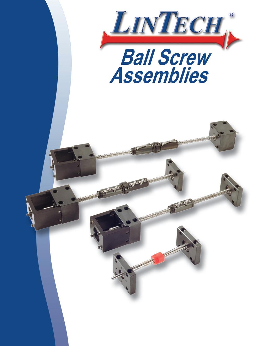
21 Ball Screw Assemblies RS, PS, GS Series Ball Screw Assemblies LINTECH's ball screw assembly products use precision machined components throughout their construction. Strict manufacturing policies and procedures ensure that every assembly meets, or in most cases, exceeds specifications. Built with exceptional quality, these positioning components offer years of reliability. ue to our unique manufacturing capabilities, LINTECH can usually deliver most ball screw assemblies in less than two weeks. With the many available options, LINTECH can manufacture a ball screw assembly capable of performing in a wide variety of applications. 19
22 Introduction Ball Screw Assemblies LINTECH's ball screw assembly positioning components are utilized in a wide variety of Motion Control applications. Welding Test Stands Part Insertion Laser Positioning Liquid ispensing Semiconductor Processing Quality Construction Gluing Pick & Place Part Scanning Inspection Stations Medical Equipment General Automation LINTECH's RS, PS, and GS series are designed to maximize performance, while providing design flexiblity. These assemblies utilize a rolled, precision rolled, or ground ball screw with preloaded or non-preloaded nuts. These steel ball screws are provided with precision machined steel supports for end bearing housings. The support housings are available in three styles (simple, fixed, and rigid). The fixed and rigid housings have precision machined shoulders that allow for a NEMA motor mount to be factory or field installed. Ball screw assemblies when used with ball nuts offer high efficiencies and long life, at an economical price. These ball screw assemblies are typically used when a complete positioning system is too costly, or does not fit the users exact positioning system requirements. When combined with linear bearings & rails, a custom positioning system can be created. These ball screw positioning components are designed to allow for numerous options: rotary encoders, different diameter and lead combinations, solid Turcite nuts, power-off electric brakes, and motor wrap packages. RS, PS, GS Series Available Options Simple, Fixed, Rigid Housings These bearing support housings provide for different thrust and speed characteristics when combined with the numerous ball screw diameter and lead combinations. NEMA Motor Mounts NEMA motor mounts can be easily mounted to any fixed or rigid housing at the factory, or in the field. These motor mounts provide for a direct interface to a NEMA 23, 34, or 42 motor. Utilizing these motor mount options ensures correct centerline alignment of the motor shaft to the ball screw shaft. Rotary Encoders Incremental rotary encoders can be mounted to a bearing support housing in order to provide positional data back to either a motion controller, or a digital display. Solid Turcite Nuts Some of the RS series screws are available with a Turcite nut. This polymer nut can provide smoother motion and less audible noise than most ball nuts that use recirculating balls. It also is ideal for corrosive environments and vertical applications. Nut Flanges Three different nut flange styles (round, vertical, and "L" bracket) are available which allow for a direct interface of the user mounted load, or carriage assembly, to the nut. All three styles are precision machined from steel for high strength and rigidity. English or Metric Versions The PS and GS series offer both English and Metric screw options. Motor mounts and nut flanges can be ordered with either English or Metic mounting hardware. For convenience, all dimensions in this catalog are shown in both English and Metric. Other Each RS, PS, and GS series ball screw assembly can accommodate power-off electric brakes for static load locking applications, numerous motor couplings for non-nema motors, and motor wrap packages for space limited applications. 20

23 Introduction RS, PS, GS Series Standard Features Precision machined steel bearing housings with black oxide finish 0 o F to +185 o F (-18 o C to +85 o C) ball nut operating temperature Fixed and rigid housings have shoulder for NEMA motor mounts Base and face mount integral to each support housing Specify desired thread length for all sizes Ball and solid Turcite nuts available Four support configurations Simple - Simple Fixed - Simple Rigid - Simple Rigid - Rigid Options CA drawings available via the internet NEMA 23, 34, and 42 motor wrap packages NEMA 23, 34, and 42 motor mounts and non-preloaded nuts Chrome plated screw and nut English and metric versions Non-NEMA motor mounts Power-off electric brakes Motor couplings Rotary encoders Nut Flanges Ball screws: Rolled - & Nuts: inch diameter, inch lead inch diameter, inch lead inch diameter, inch lead inch diameter, inch lead inch diameter, inch lead inch diameter, inch lead inch diameter, inch lead inch diameter, inch lead inch diameter, inch lead inch diameter, inch lead inch diameter, inch lead inch diameter, inch lead inch diameter, inch lead Precision - & Nuts: inch diameter, inch lead inch diameter, inch lead 16 mm diameter, 5 mm lead 16 mm diameter, 10 mm lead 16 mm diameter, 16 mm lead 20 mm diameter, 5 mm lead 20 mm diameter, 20 mm lead Ground - Nuts Only: inch diameter, inch lead inch diameter, inch lead 16 mm diameter, 5 mm lead 16 mm diameter, 16 mm lead 20 mm diameter, 5 mm lead 20 mm diameter, 20 mm lead 21
24 Ordering Guide inch screw diameter - RS Series RS050 series RS S1 - N1 - W0 - F1 - M02 - C145 - E00 - B00 - Lxxx.xxx Rolled Screw Screw iameter inch Screw Lead inch inch Support Configurations (see pages 25-26) S1 - Simple - Simple S4 - Rigid - Simple S2 - Fixed (LT) - Simple S5 - Rigid - Rigid S3 - Fixed (HT) - Simple S9 - other Nut Type (see pages 26-28) N1 - NPL ball nut (RFT) N2 - NPL ball nut (LFT) N3 - PL ball nut (RFT) N4 - PL ball nut (LFT) N5 - NPL Turcite nut (RFT) N6 - NPL Turcite nut (LFT) N7 - PL Turcite nut (RFT) N8 - PL Turcite nut (LFT) N9 - other Nut Wipers (see page 96) W0 - none W1 - Wipers on Ball Nut Nut Flange Type (see page 28) F0 - none F1 - Round flange F2 - Vertical bracket (E) F3 - Vertical bracket (M) F4 - L bracket (E) F5 - L bracket (M) F9 - other Motor Mount (see pages 29, 96-97) M00 - none M06 - NEMA 23 (RH) wrap M01 - Hand crank M07 - NEMA 23 (LH) wrap M02 - NEMA 23 mount (E) M08 - NEMA 34 (RH) wrap M03 - NEMA 23 mount (M) M04 - NEMA 34 mount (E) M09 - NEMA 34 (LH) wrap M05 - NEMA 34 mount (M) M99 - other Coupling Type (see pages 94-95) C000 - none C020 to C024 - C C999 - other C0 to C047 - C125 C125 to C129 - H C145 to C0 to C425 to C154 - H131 C6 - G C434 - G126 Rotary Encoder (see page 98) E00 - none E99 - other Power-off Brake (see page 99) B00 - none B99 - other E lines/rev E21-0 lines/rev E lines/rev B20-24 VC B21-90 VC Thread Length (see catalog page 26) Lxxx.xxx - screw thread length () Note: 22 See page 14 for a complete description of the above part number system. (E) - English Interface (LFT) - Left Facing Thread (LH) - Left Hand (LT) - Low Thrust (HT) - High Thrust (M) - Metric Interface (NPL) - Non (PL) - (RFT) - Right Facing Thread (RH) - Right Hand
25 Technical Reference inch screw diameter - RS Series Screw & Nut Specifications Model Number Nut Type iameter Lead Root iameter Ball iameter Number of Circuits Static Load lbs (kgf) ynamic Load lbs (kgf) RS inch dia inch lead Ball (N1/N2) Turcite (N5/N6) Turcite (N7/N8) (5,08) 0.5 (10,28) (3,17) n/a 2 n/a 9,0 (4263) 9,280 (4209) 800 (362) 800 (362) 1,200 (544) 1,080 (489) (45) 90 (41) RS inch dia inch lead Ball (N1/N2) Turcite (N5/N6) Turcite (N7/N8) (10,28) (3,17) n/a 2 n/a 13,350 (55) 13,130 (5955) 800 (362) 800 (362) 2,200 (997) 1,980 (898) (45) 90 (41) Other Specifications Maximum Acceleration Rate Ball nut: Turcite nut: 772 /sec 2 (19.6 m/sec 2 ) 193 /sec 2 ( 4.9 m/sec 2 ) Maximum Speed Ball nut: Turcite nut: 3000 rpm 1500 rpm Screw Material Right Hand Thread, Case Hardened Rc 58 Steel Rolled Ball Screw Screw Extensions 303 Woodruff Keyways on Extensions from Support Housings (2) Screw Maximum Length 72 (1828 mm) Screw Weight 0.66 lbs/ft (9,82 g/cm) Support Housings Support Housing Features Nut Flanges Nut Flange Features Steel with Black Oxide Finish, 45 o Chamfer x.02 inch (0,50) all Straight Edges Base or Face Mount with Integral Seals Steel with Black Oxide Finish English or Metric Load Mounting Interface Footnotes: Load based upon 1 million (25 Km) of travel life. See page 27 for further travel life ratings. (2) Maximum stock length (not the maximum thread length with bearing housings). See page 26 for maximum thread lengths for each configuration. 23
26 Technical Reference inch screw diameter - RS Series Screw Specifications Model Number Nut Type Screw Efficiency % Lead Error inch/ft (mm/300 mm) Backlash Unidirectional Repeatability Bidirectional Repeatability RS inch dia inch lead & RS inch dia inch lead Ball (N1/N2) Turcite (N5/N6) Turcite (N7/N8) (0,075) (0,203) +/ (0,203) / (0,075) to to to to (0,2082) (0,2082) Assembly Specifications Model Number Nut Type Simple-Simple Breakaway Torque oz-in (N-m) Fixed(LT)-Simple Fixed(HT)-Simple Rigid-Simple Rigid-Rigid Ball (N1/N2) 8 (0,06) 10 (0,07) 20 (0,14) 20 (0,14) 30 (0,21) RS inch dia inch lead Turcite (N5/N6) 15 (0,11) 10 (0,07) 20 (0,14) 15 (0,11) 30 (0,21) 30 (0,21) 30 (0,21) 30 (0,21) (0,28) (0,28) Turcite (N7/N8) (0,18) (0,21) (0,32) (0,32) 55 (0,39) Ball (N1/N2) 10 (0,07) 15 (0,11) 25 (0,18) 25 (0,18) 35 (0,25) RS inch dia inch lead Turcite (N5/N6) 25 (0,18) 20 (0,14) 30 (0,21) 25 (0,18) (0,28) 35 (0,25) (0,28) 35 (0,25) 45 (0,32) 45 (0,32) Turcite (N7/N8) (0,25) (0,28) (0,35) (0,35) (0,42) 24
27 Technical Reference inch screw diameter - RS Series Support Housing Specifications Support Housing Life millions of screw revolutions Simple Support Housing Thrust Load Capacity - (Axial) lbs (kgf) Fixed (LT) Fixed (HT) Rigid Static 1,076 (488) 1,355 (615) 2,1 (980) 2,1 (980) 1 1,076 (488) 1,355 (615) 1,955 (887) 1,955 (887) (413) 1,145 (519) 1,550 (703) 1,550 (703) (2) 665 (302) 905 (410) 905 (410) (141) 395 (179) 530 (2) 530 (2) 245 (111) 305 (138) 420 (190) 420 (190) (66) 180 (82) 245 (111) 245 (111) Support Housing Life Thrust force applied in either direction Support Housing Thrust Load Capacity (lbs) Fixed (HT) & Rigid Fixed (LT) Simple Life (millions of screw revolutions) Note: Multiply screw revolutions by the screw lead in order to convert to (or mm) traveled by the nut. 25
28 Technical Reference inch screw diameter - RS Series Available Configurations Simple-Simple (1739,9) Rigid-Simple (1701,8) Fixed-Simple Rigid-Rigid (1714,5) (1651,0) Overall Length iagram (65,07) (2) S1 L xxx.xxx (2) S2.374 (9,49) 303 Woodruff Keyway o.312 (7,92) rive End Housing Note: (3) N Screw Nut (NPL) nut with Right Facing Threads (RFT) shown for illustration purposes.374 (9,49) 303 Woodruff Keyway o.312 (7,92) (28,58) (4) Centerline To Centerline of 1st mounting holes +/ (0,38) (25,) - Net useable travel (nut hard-stop to hard-stop) = L - N - Overall length with NEMA 23 mount: - Overall length without motor mount: () = S1 + L + S = 65,07 + S1 + L + S2 + 25, () = S1 + L + S = 28,58 + S1 + L + S2 + 25, (see above for maximum "L" value) (see above for maximum "L" value) Footnotes: Maximum available standard screw thread length for the bearing support housing configuration shown. (2) Fixed-simple support configuration shown for reference. See page 29 for length values for simple, fixed, and rigid housings. (3) See page 28 for available nut styles. Refer to A1 & A2 values for the nut length. See page 96 for wiper kit lengths. (4) Tolerance shown is for base mounted support housings. Tolerance also applies to face mounted support housings. 26
29 Technical Reference inch screw diameter - RS Series Performance Charts Simple-Simple Maximum Compression Load X simple-simple lbs (kgf) rigid-simple lbs (kgf) rigid-rigid lbs (kgf) X 20 (508) (1016) (1524) (343) (86) (38) (686) (171) (76) (1372) (343) (152) X Rigid-Simple Rigid-Rigid Maximum Load (lbs) RS RS X simple-simple rigid-simple rigid-rigid Maximum "X" distance between bearing support and Load () 70 (2) Maximum Speed Screw Travel Life simple-simple rigid-simple rigid-rigid rpm rpm rpm Life millions of (km) lbs (kgf) lbs (kgf) Turcite Nut lbs (kgf) 23 (584) (25) 1200 (544) 2200 (997) (45) (1016) (50) 970 (4) 1780 (807) 80 (36) (1524) (1270) 350 (158) 6 (290) 29 (13) 70 (1778) (25) 290 (131) 530 (2) 24 (11) 3000 Speed (rev/min of the screw) simple-simple rigid-simple rigid-rigid ynamic Load (lbs) - seen by screw RS RS Turcite Nut Maximum "" distance between bearing supports () Travel Life (millions of ) Footnotes: Refer to the simple-simple support lengths for fixed-simple configurations. A fixed housing performs like a simple housing for critical speed and compression load specifications. Maximum speeds may not be reached using a Turcite nut due to system friction. (2) Multiply life value from chart (or graph) by 0.90 to obtain the life for a preloaded ball nut. 27
30 Technical Reference inch screw diameter - RS Series Nut imensions - Style A - Style B E A1 C E A1 C B B F T F T E - Style C (Turcite) A1 C - Styles A, B & C A2 G T.203 (5,15) spanner wrench hole size Nut Flange imensions 0.38 lbs (0,17 kg) Round Flange Vertical Bracket "L" Bracket 0.27 lbs (0,12 kg).750 (19,05) lbs (0,23 kg).750 (19,05).750 (19,05).750 (19,05) (4).281 (7,13) ia. Thru Holes on 2.09 (53,08) ia. BC (2).50 (12,7) eep Holes English (F2): #10-32 thd. Metric (F3): M5 thd..195 (4,95) (4) Holes English (F4): #10-32 thd. Metric (F5): M5 thd..390 (9,90) (44,45) 2.63 (66,80) (34,92) (53,97) (34,92) (53,97).390 (9,90).390 (9,90) (38,10).390 (9,90) (38,10).390 (9,90) Model Number Nut Style A1 A2 B C Nut imensions E F T - "V" Threads (2) G Nut (3) Weight lbs (kg) RS A 2.7 (70,10) (153,67) (27,10) (9,90) (16,89) (34,01) (21,59) 15 / UN-2A (23,81-16 UN-2A) (36,07) 0.75 (0,34) RS B 2.7 (70,10) (153,67) (27,18) (9,90) (16,94) (41,) 0.8 (21,84) 15 / UN-2A (23,81-16 UN-2A) (36,07) 0.50 (0,22) RS C (25,91) (64,77) n/a (9,90) n/a (25,) n/a 15 / UN-2A (23,81-16 UN-2A) n/a 0.20 (0,09) RS C (25,91) (64,77) n/a (9,90) n/a (25,) n/a 15 / UN-2A (23,81-16 UN-2A) n/a 0.20 (0,09) Footnotes: This is the length for a preloaded nut. nut consists of two (2) non-preloaded nuts with a locking spanner nut, and belville springs. (2) All flange threads are internal (Type 2B) to match the external nut threads. (3) Weight of the non-preloaded nut. Multiply value by 2.1 to obtain the weight for the preloaded nut assembly. 28
31 Technical Reference inch screw diameter - RS Series Support Housing imensions (63,50).625 (15,87) (44,45) (50,80) (4).343 (8,71) ia.thru Holes (4) 8-32 x.37 (9,39) eep on (44,45) BC (31,75) Simple.313 (7,95) (2).343 (8,71) ia. Thru Holes,.504 (12,8) ia. C' Bored x.57 (14,47) eep.313 (7,95) (41,27) (82,55) 1.1 lbs (0,50 kg) rive End.625 (15,87).625 (15,87) non-rive End (63,50).625 (15,87) (44,45) (50,80) (4).343 (8,71) ia.thru Holes (4) 8-32 x.37 (9,39) eep on (44,45) BC (31,75) Fixed (4).343 (8,71) ia. Thru Holes,.504 (12,8) ia. C' Bored x.57 (14,47) eep (2) x.43 (10,92) eep, both sides (28,57).750 (19,05) (41,27) (82,55).250 (6,35) 2.6 lbs (1,18 kg).688 (17,47).125 (3,17) (41,27) (63,50).625 (15,87) (44,45) (50,80) (4).343 (8,71) ia.thru Holes (4) 8-32 x.37 (9,39) eep on (44,45) BC (31,75) Rigid (4).343 (8,71) ia. Thru Holes,.504 (12,8) ia. C' Bored x.57 (14,47) eep (2) x.43 (10,92) eep, both sides (28,57) (34,92) (41,27) (82,55).250 (6,35) 3.8 lbs (1,72 kg).688 (17,47).125 (3,17) (57,15) NEMA 23 Motor Mount NEMA 34 Motor Mount.063 (1,) 0.9 lbs (0,41 kg) 2.3 (59,44) 1.4 lbs (0,64 kg) 2.3 (59,44) (4) Holes on (66,67) BC ia. English (M02): #10-24 thd. Metric (M03): M5 thd (38,15) Pilot ia. TYP (36,50) (65,07).313 (7,95) (4) Holes on (98,42) BC ia. English (M04): #10-24 thd. Metric (M05): M5 thd (65,07) (73,07) Pilot ia. TYP (49,20).313 (7,95) (57,15) (85,72) (82,55) (28,57) (2).221 (5,61) ia.thru Holes,.344 (8,73) ia. C' Bored x.125 (3,17) eep, both sides (85,72) (42,88).438 (11,13) (2).221 (5,61) ia.thru Holes,.344 (8,73) ia. C' Bored x.125 (3,17) eep, both sides 29
32 Ordering Guide inch screw diameter - RS Series RS S1 - N1 - W0 - F1 - M02 - C155 - E00 - B00 - Lxxx.xxx Rolled Screw Screw iameter inch Screw Lead inch inch Support Configurations (see pages 33-34) S1 - Simple - Simple S4 - Rigid - Simple S2 - Fixed (LT) - Simple S5 - Rigid - Rigid S3 - Fixed (HT) - Simple S9 - other Nut Type (see pages 34-36) N1 - NPL ball nut (RFT) N2 - NPL ball nut (LFT) N3 - PL ball nut (RFT) N4 - PL ball nut (LFT) N5 - NPL Turcite nut (RFT) N6 - NPL Turcite nut (LFT) N7 - PL Turcite nut (RFT) N8 - PL Turcite nut (LFT) N9 - other Nut Wipers (see page 96) W0 - none W1 - Wipers on Ball Nut Nut Flange Type (see page 36) F0 - none F1 - Round flange F2 - Vertical bracket (E) F3 - Vertical bracket (M) F4 - L bracket (E) F5 - L bracket (M) F9 - other Motor Mount (see pages 37, 96-97) M00 - none M06 - NEMA 23 (RH) wrap M01 - Hand crank M07 - NEMA 23 (LH) wrap M02 - NEMA 23 mount (E) M08 - NEMA 34 (RH) wrap M03 - NEMA 23 mount (M) M04 - NEMA 34 mount (E) M09 - NEMA 34 (LH) wrap M05 - NEMA 34 mount (M) M99 - other Coupling Type (see pages 94-95) C000 - none C025 to C029 - C C999 - other C048 to C055 - C125 C130 to C134 - H C155 to C7 to C435 to C164 - H131 C413 - G C444 - G126 Rotary Encoder (see page 98) E00 - none E99 - other Power-off Brake (see page 99) B00 - none B99 - other E lines/rev E21-0 lines/rev E lines/rev B20-24 VC B21-90 VC Thread Length (see page 34) Lxxx.xxx - screw thread length () Note: 30 See page 14 for a complete description of the above part number system. (E) - English Interface (LFT) - Left Facing Thread (LH) - Left Hand (LT) - Low Thrust (HT) - High Thrust (M) - Metric Interface (NPL) - Non (PL) - (RFT) - Right Facing Thread (RH) - Right Hand
33 Technical Reference inch screw diameter - RS Series Screw & Nut Specifications Model Number Nut Type iameter Lead Root iameter Ball iameter Number of Circuits Static Load lbs (kgf) ynamic Load lbs (kgf) RS inch dia inch lead Ball (N1/N2) Turcite (N5/N6) Turcite (N7/N8) (15,87) (5,08) (12,77) (3,17) n/a 1 n/a 6,150 (2790) 6,070 (2753) 800 (362) 800 (362) 800 (363) 720 (326) (45) 90 (41) RS inch dia inch lead Ball (N1/N2) Turcite (N5/N6) Turcite (N7/N8) (15,87) (25,) (12,82) (3,17) n/a 2 n/a 2,425 (1) 2,390 (1084) 800 (362) 800 (362) 590 (267) 530 (2) (45) 90 (41) Other Specifications Maximum Acceleration Rate Ball nut: Turcite nut: 772 /sec 2 (19.6 m/sec 2 ) 193 /sec 2 ( 4.9 m/sec 2 ) Maximum Speed Ball nut: Turcite nut: 3000 rpm 1500 rpm Screw Material Right Hand Thread, Case Hardened Rc 58 Steel Rolled Ball Screw Screw Extensions 303 Woodruff Keyways on Extensions from Support Housings (2) Screw Maximum Length 72 (1828 mm) Screw Weight 0.92 lbs/ft (13,7 g/cm) Support Housings Support Housing Features Nut Flanges Nut Flange Features Steel with Black Oxide Finish, 45 o Chamfer x.02 inch (0,50) all Straight Edges Base or Face Mount with Integral Seals Steel with Black Oxide Finish English or Metric Load Mounting Interface Footnotes: Load based upon 1 million (25 Km) of travel life. See page 35 for further travel life ratings. (2) Maximum stock length (not the maximum thread length with bearing housings). See page 34 for maximum thread lengths for each configuration. 31
34 Technical Reference inch screw diameter - RS Series Screw Specifications Model Number Nut Type Screw Efficiency % Lead Error inch/ft (mm/300 mm) Backlash Unidirectional Repeatability Bidirectional Repeatability RS inch dia inch lead Ball (N1/N2) Turcite (N5/N6) Turcite (N7/N8) (0,075) (0,075) (0,203) (0,203) 0 +/ / to to to to (0,2082) (0,2082) RS inch dia inch lead Ball (N1/N2) Turcite (N5/N6) Turcite (N7/N8) (0,203) / (0,099) (0,099) (0,203) 0 +/ to to to to (0,2082) (0,2082) Assembly Specifications Model Number Nut Type Simple-Simple Breakaway Torque oz-in (N-m) Fixed(LT)-Simple Fixed(HT)-Simple Rigid-Simple Rigid-Rigid Ball (N1/N2) 8 (0,06) 10 (0,07) 20 (0,14) 20 (0,14) 30 (0,21) RS inch dia inch lead Turcite (N5/N6) 15 (0,11) 10 (0,07) 20 (0,14) 15 (0,11) 30 (0,21) 30 (0,21) 30 (0,21) 30 (0,21) (0,28) (0,28) Turcite (N7/N8) (0,18) (0,21) (0,32) (0,32) 55 (0,39) Ball (N1/N2) 15 (0,11) 25 (0,18) (0,28) (0,28) 50 (0,35) RS inch dia inch lead Turcite (N5/N6) 30 (0,21) 25 (0,18) (0,28) 35 (0,25) 55 (0,39) 50 (0,35) 55 (0,39) 50 (0,35) 65 (0,45) (0,42) Turcite (N7/N8) (0,35) (0,42) (0,53) (0,53) 85 (0,) 32
35 Technical Reference inch screw diameter - RS Series Support Housing Specifications Support Housing Life millions of screw revolutions Simple Support Housing Thrust Load Capacity - (Axial) lbs (kgf) Fixed (LT) Fixed (HT) Rigid Static 1,370 (621) 1,725 (782) 3,105 (18) 3,105 (18) 1 1,370 (621) 1,725 (782) 2,875 (1304) 2,875 (1304) 2 1,215 (551) 1,530 (694) 2,195 (996) 2,195 (996) (322) 895 (6) 1,295 (587) 1,295 (587) (186) 525 (238) 790 (358) 790 (358) 330 (150) 415 (188) 630 (286) 630 (286) (88) 2 (109) 365 (166) 365 (166) Support Housing Life Thrust force applied in either direction Support Housing Thrust Load Capacity (lbs) Fixed (HT) & Rigid Fixed (LT) Simple Life (millions of screw revolutions) Note: Multiply screw revolutions by the screw lead in order to convert to (or mm) traveled by the nut. 33
36 Technical Reference inch screw diameter - RS Series Available Configurations Simple-Simple (1739,9) Rigid-Simple (1689,1) Fixed-Simple Rigid-Rigid (1701,8) (1644,6) Overall Length iagram (65,07) (2) S1 L xxx.xxx (2) S2.374 (9,49) 303 Woodruff Keyway o.375 rive End Housing Note: (3) N Screw Nut (NPL) nut with Right Facing Threads (RFT) shown for illustration purposes.374 (9,49) 303 Woodruff Keyway o (28,58) (4) Centerline To Centerline of 1st mounting holes +/ (0,38) (25,) - Net usable travel (nut hard-stop to hard-stop) = L - N - Overall length with NEMA 23 mount: - Overall length without motor mount: () = S1 + L + S = 65,07 + S1 + L + S2 + 25, () = S1 + L + S = 28,58 + S1 + L + S2 + 25, (see above for maximum "L" value) (see above for maximum "L" value) Footnotes: Maximum available standard screw thread length for the bearing support housing configuration shown. (2) Fixed-simple support configuration shown for reference. See page 37 for length values for simple, fixed, and rigid housings. (3) See page 36 for available nut styles. Refer to A1 & A2 values for the nut length. See page 96 for wiper kit lengths. (4) Tolerance shown is for base mounted support housings. Tolerance also applies to face mounted support housings. 34
37 Technical Reference inch screw diameter - RS Series Performance Charts Simple-Simple Maximum Compression Load X simple-simple lbs (kgf) rigid-simple lbs (kgf) rigid-rigid lbs (kgf) X 20 (508) (1016) (1524) (816) (204) (91) (1) (8) (181) (1) (816) (363) X Rigid-Simple Rigid-Rigid Maximum Load (lbs) RS RS062 X simple-simple rigid-simple rigid-rigid Maximum Speed Maximum "X" distance between bearing support and Load () (2) Screw Travel Life simple-simple rigid-simple rigid-rigid rpm rpm rpm Life millions of (km) lbs (kgf) 062 lbs (kgf) Turcite Nut lbs (kgf) 27 (686) (25) 800 (363) 590 (268) (45) (1016) (50) 6 (290) 480 (218) 80 (36) (1524) (1270) 230 (104) 170 (77) 29 (13) 70 (1778) (25) 190 (186) 1 (64) 24 (11) 3000 Speed (rev/min of the screw) simple-simple rigid-simple rigid-rigid Maximum "" distance between bearing supports () ynamic Load (lbs) - seen by screw RS RS062 Turcite Nut Travel Life (millions of ) Footnotes: Refer to the simple-simple support lengths for fixed-simple configurations. A fixed housing performs like a simple housing for critical speed and compression load specifications. Maximum speeds may not be reached using a Turcite nut due to system friction. (2) Multiply life value from chart (or graph) by 0.90 to obtain the life for a preloaded ball nut. 35
38 Technical Reference inch screw diameter - RS Series Nut imensions - Style A - Style B E A1 C E A1 C B B F T F T E - Style C (Turcite) A1 C - Styles A, B & C A2 G T.203 (5,15) spanner wrench hole size Nut Flange imensions 0.55 lbs (0,25 kg) Round Flange Vertical Bracket 0.35 lbs (0,16 kg).750 (19,05) lbs (0,28 kg) "L" Bracket.750 (19,05).750 (19,05).750 (19,05) (4).281 (7,13) ia. Thru Holes on 2.09 (53,08) ia. BC (2).50 (12,7) eep Holes English (F2): 1 / 4-28 thd. Metric (F3): M6 thd..250 (6,35) (4) Holes English (F4): 1 / 4-28 thd. Metric (F5): M6 thd (44,45) 2.63 (66,80) (34,92) (53,97) (34,92) (53,97) (38,10) (38,10).500 Model Number Nut Style A1 A2 B C Nut imensions E F T - "V" Threads (2) G Nut (3) Weight lbs (kg) RS A (43,69) (95,25) (28,70) (12,83) (19,99) 1.3 (34,54) (20,32) 15 / UN-2A (23,81-16 UN-2A) (36,07) 0.50 (0,22) RS062 B (43,69) (95,25) (28,57) (19,30) (42,01) (21,00) 15 / UN-2A (23,81-16 UN-2A) (36,07) 0.28 (0,13) RS C (28,70) (72,39) n/a (12,83) n/a (25,) n/a 15 / UN-2A (23,81-16 UN-2A) n/a 0.20 (0,09) RS062 C (28,70) (72,39) n/a n/a (25,) n/a 15 / UN-2A (23,81-16 UN-2A) n/a 0.20 (0.09) Footnotes: This is the length for a preloaded nut. nut consists of two (2) non-preloaded nuts with a locking spanner nut, and belville springs. (2) All flange threads are internal (Type 2B) to match the external nut threads. (3) Weight of the non-preloaded nut. Multiply value by 2.1 to obtain the weight for the preloaded nut assembly. 36
39 Technical Reference inch screw diameter - RS Series Support Housing imensions (63,50).625 (15,87) (44,45) (50,80) (4).343 (8,71) ia.thru Holes (4) 8-32 x.37 (9,39) eep on (44,45) BC (31,75) Simple.313 (7,95) (2).343 (8,71) ia. Thru Holes,.504 (12,8) ia. C' Bored x.57 (14,47) eep.313 (7,95) (41,27) (82,55) 1.1 lbs (0,50 kg) rive End.625 (15,87).625 (15,87) non-rive End (63,50).625 (15,87) (44,45) (50,80) (4).343 (8,71) ia.thru Holes (4) 8-32 x.37 (9,39) eep on (44,45) BC (31,75) Fixed (2) x.43 (10,92) eep, both sides (4).343 (8,71) ia. Thru Holes,.504 (12,8) ia. C' Bored x.57 (14,47) eep (28,57).750 (19,05) (41,27) (82,55).250 (6,35) 2.7 lbs (1,22 kg).688 (17,47).125 (3,17) (44,45) (63,50).625 (15,87) (44,45) (50,80) (4).343 (8,71) ia.thru Holes (4) 8-32 x.37 (9,39) eep on (44,45) BC (31,75) Rigid (2) x.43 (10,92) eep, both sides (4).343 (8,71) ia. Thru Holes,.504 (12,8) ia. C' Bored x.57 (14,47) eep (28,57) (38,10) (41,27) (82,55).250 (6,35) 3.9 lbs (1,77 kg).688 (17,47).125 (3,17) (63,50) NEMA 23 Motor Mount NEMA 34 Motor Mount.063 (1,) 0.9 lbs (0,41 kg) 2.3 (59,44) 1.4 lbs (0,64 kg) 2.3 (59,44) (4) Holes on (66,67) BC ia. English (M02): #10-24 thd. Metric (M03): M5 thd (38,15) Pilot ia. TYP (36,50) (65,07).313 (7,95) (4) Holes on (98,42) BC ia. English (M04): #10-24 thd. Metric (M05): M5 thd (65,07) (73,07) Pilot ia. TYP (49,20).313 (7,95) (57,15) (85,72) (82,55) (28,57) (2).221 (5,61) ia.thru Holes,.344 (8,73) ia. C' Bored x.125 (3,17) eep, both sides (85,72) (42,88).438 (11,13) (2).221 (5,61) ia.thru Holes,.344 (8,73) ia. C' Bored x.125 (3,17) eep, both sides 37
40 Ordering Guide inch screw diameter - RS Series RS075 series RS S1 - N1 - W0 - F1 - M02 - C165 - E00 - B00 - Lxxx.xxx Rolled Screw Screw iameter inch Screw Lead inch inch Support Configurations (see pages 41-42) S1 - Simple - Simple S4 - Rigid - Simple S2 - Fixed (LT) - Simple S5 - Rigid - Rigid S3 - Fixed (HT) - Simple S9 - other Nut Type (see pages 42-44) N1 - NPL ball nut (RFT) N2 - NPL ball nut (LFT) N3 - PL ball nut (RFT) N4 - PL ball nut (LFT) N5 - NPL Turcite nut (RFT) N6 - NPL Turcite nut (LFT) N7 - PL Turcite nut (RFT) N8 - PL Turcite nut (LFT) N9 - other Nut Wipers (see page 96) W0 - none W1 - Wipers on Ball Nut Nut Flange Type (see page 44) F0 - none F1 - Round flange F2 - Vertical bracket (E) F3 - Vertical bracket (M) F4 - L bracket (E) F5 - L bracket (M) F9 - other Motor Mount (see pages 45, 96-97) M00 - none M06 - NEMA 23 (RH) wrap M01 - Hand crank M07 - NEMA 23 (LH) wrap M02 - NEMA 23 mount (E) M08 - NEMA 34 (RH) wrap M03 - NEMA 23 mount (M) M04 - NEMA 34 mount (E) M09 - NEMA 34 (LH) wrap M05 - NEMA 34 mount (M) M99 - other Coupling Type (see pages 94-95) C000 - none C056 to C063 - C125 C999 - other C084 to C090 - C150 C165 to C174 - H131 C201 to C445 to C481 to C211 - H163 C454 - G126 C491 - G158 Rotary Encoder (see page 98) E00 - none E99 - other Power-off Brake (see page 99) B00 - none B99 - other E lines/rev E21-0 lines/rev E lines/rev B20-24 VC B21-90 VC Thread Length (see page 42) Lxxx.xxx - screw thread length () Note: 38 See page 14 for a complete description of the above part number system. (E) - English Interface (LFT) - Left Facing Thread (LH) - Left Hand (LT) - Low Thrust (HT) - High Thrust (M) - Metric Interface (NPL) - Non (PL) - (RFT) - Right Facing Thread (RH) - Right Hand
41 Technical Reference inch screw diameter - RS Series Screw & Nut Specifications Model Number Nut Type iameter Lead Root iameter Ball iameter Number of Circuits Static Load lbs (kgf) ynamic Load lbs (kgf) RS inch dia inch lead Ball (N1/N2) Turcite (N5/N6) Turcite (N7/N8) (19,05) (5,08) (16,63) (3,17) n/a 2 n/a 18,800 (8527) 18,610 (8441) 1,500 (680) 1,500 (680) 1,900 (862) 1,710 (776) 195 (88) 175 (79) RS inch dia inch lead Ball (N1/N2) Turcite (N5/N6) Turcite (N7/N8) (19,05) (15,97) (3,96) n/a 2 n/a 24,200 (10977) 23,855 (10820) 1,500 (680) 1,500 (680) 3,450 (1565) 3,105 (18) 195 (88) 175 (79) Other Specifications Maximum Acceleration Rate Ball nut: Turcite nut: 772 /sec 2 (19.6 m/sec 2 ) 193 /sec 2 ( 4.9 m/sec 2 ) Maximum Speed Ball nut: Turcite nut: 3000 rpm 1500 rpm Screw Material Right Hand Thread, Case Hardened Rc 58 Steel Rolled Ball Screw Screw Extensions Woodruff Keyways on Support Housings rive End; 303 Opposite End (2) Screw Maximum Length 72 (1828 mm) Screw Weight 1.42 lbs/ft (21,1 g/cm) Support Housings Support Housing Features Nut Flanges Nut Flange Features Steel with Black Oxide Finish, 45 o Chamfer x.02 inch (0,50) all Straight Edges Base or Face Mount with Integral Seals Steel with Black Oxide Finish English or Metric Load Mounting Interface Footnotes: Load based upon 1 million (25 Km) of travel life. See page 43 for further travel life ratings. (2) Maximum stock length (not the maximum thread length with bearing housings). See page 42 for maximum thread lengths for each configuration. 39
42 Technical Reference inch screw diameter - RS Series Screw Specifications Model Number Nut Type Screw Efficiency % Lead Error inch/ft (mm/300 mm) Backlash Unidirectional Repeatability Bidirectional Repeatability RS inch dia inch lead & RS inch dia inch lead Ball (N1/N2) Turcite (N5/N6) Turcite (N7/N8) (0,075) (0,075) (0,203) (0,203) 0 +/ / to to to to (0,2082) (0,2082) Assembly Specifications Model Number Nut Type Simple-Simple Breakaway Torque oz-in (N-m) Fixed(LT)-Simple Fixed(HT)-Simple Rigid-Simple Rigid-Rigid Ball (N1/N2) 10 (0,07) 20 (0,14) 30 (0,21) 30 (0,21) 45 (0,32) RS inch dia inch lead Turcite (N5/N6) 20 (0,14) 15 (0,11) 30 (0,21) 25 (0,18) (0,28) 35 (0,25) (0,28) 35 (0,25) 55 (0,39) 50 (0,35) Turcite (N7/N8) (0,21) (0,28) (0,35) (0,35) 65 (0,45) Ball (N1/N2) 15 (0,11) 25 (0,18) 35 (0,25) 35 (0,25) 50 (0,35) RS inch dia inch lead Turcite (N5/N6) 30 (0,21) 25 (0,18) (0,28) 35 (0,25) 50 (0,35) 45 (0,32) 50 (0,35) 45 (0,32) 65 (0,45) (0,42) Turcite (N7/N8) (0,35) (0,42) (0,49) (0,49) 85 (0,)
43 Technical Reference inch screw diameter - RS Series Support Housing Specifications Support Housing Life millions of screw revolutions Support Housing Thrust Load Capacity - (Axial) lbs (kgf) Simple Fixed (LT) Fixed (HT) Rigid Static 1,675 (7) 2,110 (957) 3,350 (1520) 3,350 (1520) 1 1,675 (7) 2,110 (957) 3,035 (1377) 3,035 (1377) 2 1,365 (619) 1,720 (780) 2,275 (1032) 2,275 (1032) (361) 1,050 (476) 1,375 (624) 1,375 (624) (211) 585 (265) 820 (372) 820 (372) 370 (168) 465 (211) 650 (295) 650 (295) (98) 270 (122) 390 (177) 390 (177) Support Housing Life Thrust force applied in either direction Support Housing Thrust Load Capacity (lbs) Fixed (HT) & Rigid Fixed (LT) Simple Life (millions of screw revolutions) Note: Multiply screw revolutions by the screw lead in order to convert to (or mm) traveled by the nut. 41
44 Technical Reference inch screw diameter - RS Series Available Configurations Simple-Simple (1739,9) Rigid-Simple (1676,4) Fixed-Simple Rigid-Rigid (1701,8) (1631,9) Overall Length iagram (65,07) (2) S1 L xxx.xxx (2) S2.374 (9,49) 4 Woodruff Keyway o.500 rive End Housing Note: (3) N Screw Nut (NPL) nut with Right Facing Threads (RFT) shown for illustration purposes.374 (9,49) 303 Woodruff Keyway o (28,58) (4) Centerline To Centerline of 1st mounting holes +/ (0,38) (25,) - Net useable travel (nut hard-stop to hard-stop) = L - N - Overall length with NEMA 23 mount: - Overall length without motor mount: () = S1 + L + S = 65,07 + S1 + L + S2 + 25, () = S1 + L + S = 28,58 + S1 + L + S2 + 25, (see above for maximum "L" value) (see above for maximum "L" value) Footnotes: Maximum available standard screw thread length for the bearing support housing configuration shown. (2) Fixed-simple support configuration shown for reference. See page 45 for length values for simple, fixed, and rigid housings. (3) See page 44 for available nut styles. Refer to A1 & A2 values for the nut length. See page 96 for wiper kit lengths. (4) Tolerance shown is for base mounted support housings. Tolerance also applies to face mounted support housings. 42
45 Technical Reference inch screw diameter - RS Series Performance Charts Simple-Simple Maximum Compression Load X simple-simple lbs (kgf) rigid-simple lbs (kgf) rigid-rigid lbs (kgf) X 20 (508) (1016) (1524) (1995) (499) (222) (3990) (998) (444) (7982) (1996) (887) Rigid-Simple RS X Rigid-Rigid Maximum Load (lbs) RS X 200 simple-simple rigid-simple rigid-rigid Maximum "X" distance between bearing support and Load () 70 (2) Maximum Speed Screw Travel Life simple-simple rigid-simple rigid-rigid rpm rpm rpm Life millions of (km) lbs (kgf) lbs (kgf) Turcite Nut lbs (kgf) 29 (737) (25) 1900 (862) 3450 (1565) 195 (88) (1016) (50) 15 (698) 2790 (1265) 1 (72) (1524) (1270) 5 (245) 990 (450) 55 (29) 70 (1778) (25) 4 (208) 820 (372) 45 (20) 3000 Speed (rev/min of the screw) simple-simple rigid-simple rigid-rigid Maximum "" distance between bearing supports () ynamic Load (lbs) - seen by screw RS RS Turcite Nut Travel Life (millions of ) Footnotes: Refer to the simple-simple support lengths for fixed-simple configurations. A fixed housing performs like a simple housing for critical speed and compression load specifications. Maximum speeds may not be reached using a Turcite nut due to system friction. (2) Multiply life value from chart (or graph) by 0.90 to obtain the life for a preloaded ball nut. 43
46 Technical Reference inch screw diameter - RS Series Nut imensions - Style A - Style B E A1 C E A1 C B B F T F T E - Style C (Turcite) A1 C - Styles A, B & C A2 G T.266 (6,75) spanner wrench hole size Nut Flange imensions 0.55 lbs (0,25 kg) Round Flange Vertical Bracket "L" Bracket 0.31 lbs (0,14 kg).750 (19,05) lbs (0,25 kg).750 (19,05) (31,75) (25,) (4).281 (7,13) ia. Thru Holes on 2.09 (53,08) ia. BC (2).50 (12,7) eep Holes English (F2): 1 / 4-28 thd. Metric (F3): M6 thd..250 (6,35) (4) Holes English (F4): 1 / 4-28 thd. Metric (F5): M6 thd (69,85) 2.63 (66,80) (34,92) (57,15) (34,92) (57,15).265 (6,73) (38,10) (38,10).500 Model Number Nut Style A1 A2 B C Nut imensions E F T - "V" Threads (2) G Nut (3) Weight lbs (kg) RS A (73,) (154,43) (33,45) (12,82) (23,29) (38,63) 0.9 (23,87) UNS-2A (29,79-18 UNS-2A) (42,41) 1.00 (0,45) RS B 2.9 (74,67) (156,97) (33,45) (12,82) (24,96) (50,39) 1.0 (26,92) 1 1 / 4-16 UN-2A (31,75-16 UN-2A) (42,41) 1.00 (0,45) RS C (38,35) (89,41) n/a (12,82) n/a (38,10) n/a UNS-2A (29,79-18 UNS-2A) n/a 0.35 (0,15) RS C (38,35) (89,41) n/a (12,82) n/a (38,10) n/a 1 1 / 4-16 UN-2A (31,75-16 UN-2A) n/a 0.35 (0,15) Footnotes: This is the length for a preloaded nut. nut consists of two (2) non-preloaded nuts with a locking spanner nut, and belville springs. (2) All flange threads are internal (Type 2B) to match the external nut threads. (3) Weight of the non-preloaded nut. Multiply value by 2.1 to obtain the weight for the preloaded nut assembly. 44
47 Technical Reference inch screw diameter - RS Series Support Housing imensions (63,50).625 (15,87) (44,45) (50,80) (4).343 (8,71) ia.thru Holes (4) 8-32 x.37 (9,39) eep on (44,45) BC (31,75) Simple.313 (7,95) (2).343 (8,71) ia. Thru Holes,.504 (12,8) ia. C' Bored x.57 (14,47) eep.313 (7,95) (41,27) (82,55) 1.1 lbs (0,50 kg) rive End.625 (15,87).625 (15,87) non-rive End (63,50).625 (15,87) (44,45) (50,80) (4).343 (8,71) ia.thru Holes (4) 8-32 x.37 (9,39) eep on (44,45) BC (31,75) Fixed (2) x.43 (10,92) eep, both sides.750 (19,05) (4).343 (8,71) ia. Thru Holes,.504 (12,8) ia. C' Bored x.57 (14,47) eep (28,57) (41,27) (82,55).250 (6,35) 2.7 lbs (1,22 kg).688 (17,47).125 (3,17) (44,45) (63,50) (15,87) (50,80) (4).343 (8,71) ia.thru Holes (44,45) (41,27) (82,55) (4) 8-32 x.37 (9,39) eep on (44,45) BC (31,75).250 (6,35) Rigid 4.0 lbs (1,81 kg) (2) x.43 (10,92) eep, both sides (4).343 (8,71) ia. Thru Holes,.504 (12,8) ia. C'Bored x.57 (14,47) eep.688 (17,47) (28,57) (44,45).125 (3,17) (69,85).500 NEMA 23 Motor Mount NEMA 34 Motor Mount.063 (1,) 0.9 lbs (0,41 kg) 2.3 (59,44) 1.4 lbs (0,64 kg) 2.3 (59,44) (4) Holes on (66,67) BC ia. English (M02): #10-24 thd. Metric (M03): M5 thd (38,15) Pilot ia. TYP (36,50) (65,07).313 (7,95) (4) Holes on (98,42) BC ia. English (M04): #10-24 thd. Metric (M05): M5 thd (65,07) (73,07) Pilot ia. TYP (49,20).313 (7,95) (57,15) (85,72) (82,55) (28,57) (2).221 (5,61) ia.thru Holes,.344 (8,73) ia. C' Bored x.125 (3,17) eep, both sides (85,72) (42,88).438 (11,13) (2).221 (5,61) ia.thru Holes,.344 (8,73) ia. C' Bored x.125 (3,17) eep, both sides 45
48 Ordering Guide inch screw diameter - RS Series RS series RS S1 - N1 - W0 - F1 - M04 - C175 - E00 - B00 - Lxxx.xxx Rolled Screw Screw iameter inch Screw Lead inch inch inch Support Configurations (see pages 49-50) S1 - Simple - Simple S4 - Rigid - Simple S2 - Fixed (LT) - Simple S5 - Rigid - Rigid S3 - Fixed (HT) - Simple S9 - other Nut Type (see pages 50-52) N1 - NPL ball nut (RFT) N2 - NPL ball nut (LFT) N3 - PL ball nut (RFT) N4 - PL ball nut (LFT) N5 - NPL Turcite nut (RFT) N6 - NPL Turcite nut (LFT) N7 - PL Turcite nut (RFT) N8 - PL Turcite nut (LFT) N9 - other Nut Wipers (see page 96) W0 - none W1 - Wipers on Ball Nut Nut Flange Type (see page 52) F0 - none F1 - Round flange F2 - Vertical bracket (E) F3 - Vertical bracket (M) F4 - L bracket (E) F5 - L bracket (M) F9 - other Motor Mount (see pages 53, 96-97) M00 - none M04 - NEMA 34 mount (E) M05 - NEMA 34 mount (M) M08 - NEMA 34 (RH) wrap M09 - NEMA 34 (LH) wrap M10 - NEMA 42 mount (E) M11 - NEMA 42 mount (M) M12 - NEMA 42 (RH) wrap M13 - NEMA 42 (LH) wrap M99 - other Coupling Type (see pages 94-95) C000 - none C064 to C068 - C125 C999 - other C091 to C097 - C150 C175 to C182 - H131 C212 to C455 to C492 to C222 - H163 C462 - G126 C502 - G158 Rotary Encoder (see page 98) E00 - none E99 - other Power-off Brake (see page 99) B00 - none B99 - other E lines/rev E25-0 lines/rev E lines/rev B22-24 VC B23-90 VC Thread Length (see page 50) Lxxx.xxx - screw thread length () Note: 46 See page 14 for a complete description of the above part number system. (E) - English Interface (LFT) - Left Facing Thread (LH) - Left Hand (LT) - Low Thrust (HT) - High Thrust (M) - Metric Interface (NPL) - Non (PL) - (RFT) - Right Facing Thread (RH) - Right Hand
49 Technical Reference inch screw diameter - RS Series Screw & Nut Specifications Model Number Nut Type iameter Lead Root iameter Ball iameter Number of Circuits Static Load lbs (kgf) ynamic Load lbs (kgf) RS inch dia inch lead Ball (N1/N2) Turcite (N5/N6) Turcite (N7/N8) (25,) (6,35) (21,23) (3,96) n/a 2 n/a 30,750 (13947) 30,415 (13796) 1,500 (680) 1,500 (680) 3,350 (1519) 3,015 (1367) 195 (88) 175 (79) RS inch dia inch lead Ball (N1/N2) Turcite (N5/N6) Turcite (N7/N8) (25,) (22,32) (3,96) n/a 2 n/a 32,300 (14650) 31,905 (14471) 1,500 (680) 1,500 (680) 3,950 (1791) 3,555 (1612) 195 (88) 175 (79) RS inch dia inch lead Ball (N1/N2) Turcite (N5/N6) Turcite (N7/N8) (25,) (25,) (21,23) (3,96) n/a 2 n/a 13,750 (6236) 13,525 (6134) 1,500 (680) 1,500 (680) 2,250 (1020) 2,025 (918) 195 (88) 175 (79) Other Specifications Maximum Acceleration Rate Ball nut: Turcite nut: 772 /sec 2 (19.6 m/sec 2 ) 193 /sec 2 ( 4.9 m/sec 2 ) Maximum Speed Ball nut: Turcite nut: 3000 rpm 1500 rpm Screw Material Right Hand Thread, Case Hardened Rc 58 Steel Rolled Ball Screw Screw Extensions 5 Woodruff Keyways on Extensions from Support Housings (2) Screw Maximum Length 144 (3657 mm) Screw Weight 2.33 lbs/ft (34,7 g/cm) Support Housings Support Housing Features Nut Flanges Nut Flange Features Steel with Black Oxide Finish, 45 o Chamfer x.03 inch (0,76) all Straight Edges Base or Face Mount with Integral Seals Steel with Black Oxide Finish English or Metric Load Mounting Interface Footnotes: Load based upon 1 million (25 Km) of travel life. See page 51 for further travel life ratings. (2) Maximum stock length (not the maximum thread length with bearing housings). See page 50 for maximum thread lengths for each configuration. 47
50 Technical Reference inch screw diameter - RS Series Screw Specifications Model Number Nut Type Screw Efficiency % Lead Error inch/ft (mm/300 mm) Backlash Unidirectional Repeatability Bidirectional Repeatability RS inch dia inch lead & RS inch dia inch lead & Ball (N1/N2) Turcite (N5/N6) RS inch dia inch lead Turcite (N7/N8) (0,229) (0,229) (0,229) (0,229) 0 +/ / to to to to (0,2300) (0,2300) Assembly Specifications Model Number Nut Type Simple-Simple Breakaway Torque oz-in (N-m) Fixed(LT)-Simple Fixed(HT)-Simple Rigid-Simple Rigid-Rigid Ball (N1/N2) 20 (0,14) 25 (0,18) 35 (0,25) 35 (0,25) 50 (0,35) RS inch dia inch lead Turcite (N5/N6) 35 (0,25) 30 (0,21) (0,28) 35 (0,25) 50 (0,35) 45 (0,32) 50 (0,35) 45 (0,32) 65 (0,45) (0,42) Turcite (N7/N8) (0,39) (0,42) (0,49) (0,49) 85 (0,) Ball (N1/N2) 25 (0,18) 30 (0,21) 50 (0,35) 50 (0,35) 65 (0,45) RS inch dia inch lead Turcite (N5/N6) 45 (0,32) (0,28) 50 (0,35) 45 (0,32) 70 (0,49) 65 (0,45) 70 (0,49) 65 (0,45) 80 (0,56) 80 (0,56) Turcite (N7/N8) (0,53) (0,56) (0,70) (0,70) 115 (0,81) Ball (N1/N2) 30 (0,21) 35 (0,25) 55 (0,39) 55 (0,39) 75 (0,53) RS inch dia inch lead Turcite (N5/N6) 55 (0,39) 45 (0,32) (0,42) 50 (0,35) 80 (0,56) 70 (0,49) 80 (0,56) 70 (0,49) (0,71) 90 (0,64) Turcite (N7/N8) (0,) (0,64) (0,79) (0,79) 130 (0,92) 48
51 Technical Reference inch screw diameter - RS Series Support Housing Specifications Support Housing Life millions of screw revolutions Simple Support Housing Thrust Load Capacity - (Axial) lbs (kgf) Fixed (LT) Fixed (HT) Rigid Static 2,880 (1306) 3,630 (1646) 6,615 (3000) 6,615 (3000) 1 2,880 (1306) 3,630 (1646) 5,2 (2377) 5,2 (2377) 2 2,285 (1036) 2,880 (1306) 4,1 (1887) 4,1 (1887) 10 1,335 (6) 1,685 (764) 2,430 (1102) 2,430 (1102) (365) 990 (449) 1,420 (644) 1,420 (644) 620 (281) 795 (3) 1,130 (512) 1,130 (512) (170) 455 (206) 6 (299) 6 (299) Support Housing Life Thrust force applied in either direction Support Housing Thrust Load Capacity (lbs) Fixed (HT) & Rigid Fixed (LT) Simple Life (millions of screw revolutions) Note: Multiply screw revolutions by the screw lead in order to convert to (or mm) traveled by the nut. 49
52 Technical Reference inch screw diameter - RS Series Available Configurations Simple-Simple (3530,6) Rigid-Simple (3467,1) Fixed-Simple Rigid-Rigid (3505,2) (3390,9) Overall Length iagram (65,07) (2) S1 L xxx.xxx (2) S Woodruff Keyway o.625 (15,87) rive End Housing Note: (3) N Screw Nut (NPL) nut with Right Facing Threads (RFT) shown for illustration purposes Woodruff Keyway o.375 o.625 (15,87) (28,58) (4) Centerline To Centerline of 1st mounting holes +/ (0,38) (46,36) (25,) - Net useable travel (nut hard-stop to hard-stop) = L - N - Overall length with NEMA 23 mount: - Overall length without motor mount: () = S1 + L + S = 65,07 + S1 + L + S2 + 25, () = S1 + L + S = 28,58 + S1 + L + S2 + 25, (see above for maximum "L" value) (see above for maximum "L" value) Footnotes: Maximum available standard screw thread length for the bearing support housing configuration shown. (2) Fixed-simple support configuration shown for reference. See page 53 for length values for simple, fixed, and rigid housings. (3) See page 52 for available nut styles. Refer to A1 & A2 values for the nut length. See page 96 for wiper kit lengths. (4) Tolerance shown is for base mounted support housings. Tolerance also applies to face mounted support housings. 50
53 Technical Reference inch screw diameter - RS Series Performance Charts Simple-Simple Maximum Compression Load X simple-simple lbs (kgf) rigid-simple lbs (kgf) rigid-rigid lbs (kgf) X (1016) 80 (2032) 120 (3048) (1556) (388) (172) (3112) (776) (345) (6223) (1551) (690) X Rigid-Simple Rigid-Rigid Maximum Load (lbs) RS025 RS050 RS X 200 simple-simple rigid-simple rigid-rigid Maximum "X" distance between bearing support and Load () (2) Maximum Speed Screw Travel Life simple-simple rigid-simple rigid-rigid rpm rpm rpm Life millions of (km) 025 lbs (kgf) 050 lbs (kgf) lbs (kgf) Turcite Nut lbs (kgf) 34 (864) (25) 3350 (1520) 3950 (1792) 2250 (1020) 195 (88) (1524) (50) 2710 (1229) 3200 (1451) 1820 (825) 1 (72) (25) (1270) 990 (449) 1 (499) 670 (304) 55 (29) 1 (3556) (25) 810 (367) 970 (4) 5 (254) 45 (20) 3000 Speed (rev/min of the screw) simple-simple rigid-simple rigid-rigid Maximum "" distance between bearing supports () ynamic Load (lbs) - seen by screw RS050 RS025 RS Turcite Nut Travel Life (millions of ) Footnotes: Refer to the simple-simple support lengths for fixed-simple configurations. A fixed housing performs like a simple housing for critical speed and compression load specifications. Maximum speeds may not be reached using a Turcite nut due to system friction. (2) Multiply life value from chart (or graph) by 0.90 to obtain the life for a preloaded ball nut. 51
54 Technical Reference inch screw diameter - RS Series Nut imensions - Style A - Style B E A1 C E A1 C B B F T F T E - Style C (Turcite) A1 C - Styles A, B & C A2 G Nut Flange imensions T Round Flange Vertical Bracket "L" Bracket.500 (12,7).266 (6,75) spanner wrench hole size (30,17) (30,81) 1.11 lbs (0,50 kg) 0.67 lbs (0,30 kg) (25,4) 1.5 lbs (0,68 kg) (25,4) (4).281 (7,14) ia. Thru Holes on 2.75 (69,85) ia. BC (2).75 (19,05) eep Holes English (F2): 5 / thd. Metric (F3): M10 thd..300 (7,62) (4) Holes English (F4): 5 / thd. Metric (F5): M10 thd..500 (12,7) (76,2) (83,31) (49,22) (74,62) (49,22) (74,62).0 (15,24).0 (15,24) (50,8).0 (15,24) (50,8).0 (15,24) Model Number Nut Style A1 A2 B C Nut imensions E F T - "V" Threads (2) G Nut (3) Weight lbs (kg) RS025 A 3.1 (79,76) 6.6 (168,66) (42,98) (16,00) (30,25) (47,80) (28,45) 1 9 / UNEF-2A (39,68-18 UNEF-2A) (52,57) 1.25 (0,56) RS050 B (79,50) 6.6 (168,66) (42,98) (16,00) (30,25) (47,80) (28,45) 1 9 / UNEF-2A (39,68-18 UNEF-2A) (52,57) 1.25 (0,56) RS B 3. (78,74) (165,61) (42,98) 0.5 (15,37) (30,48) (55,17) (29,72) 1 9 / UNEF-2A (39,68-18 UNEF-2A) (52,57) 1.25 (0,56) RS025 C (38,10) (88,90) n/a 0.0 (15,24) n/a n/a 9 / UNEF-2A n/a (44,45) (39,68-18 UNEF-2A) 0.35 (0,15) RS050 C (38,10) (88,90) n/a 0.0 (15,24) n/a (44,45) n/a 1 9 / UNEF-2A (39,68-18 UNEF-2A) n/a 0.35 (0,15) RS C (38,10) (88,90) n/a 0.0 (15,24) n/a (44,45) n/a 1 9 / UNEF-2A (39,68-18 UNEF-2A) n/a 0.35 (0,15) Footnotes: This is the length for a preloaded nut. nut consists of two (2) non-preloaded nuts with a locking spanner nut, and belville springs. (2) All flange threads are internal (Type 2B) to match the external nut threads. (3) Weight of the non-preloaded nut. Multiply value by 2.1 to obtain the weight for the preloaded nut assembly. 52
55 Technical Reference inch screw diameter - RS Series Support Housing imensions (92,08) (20,65) (69,85) (4).6 (10,31) ia.thru Holes (66,68) (4) ia. x.50 (12,7) eep on (63,5) BC (46,05) Simple.375 (2).6 (10,3) ia. Thru Holes,.620 (15,75) ia. C' Bored x.75 (19,05) eep (55,58) (111,13) 2.5 lbs (1,14 kg) rive End.750 (19,05).750 (19,05) non-rive End (92,08).813 (20,65) (66,68) (55,58) (69,85) (111,13) (4).6 (10,31) ia.thru Holes (4) ia. x.50 (12,7) eep on (63,5) BC (46,05).375 Fixed 6.6 lbs (2,99 kg) (4).6 (10,3) ia. Thru Holes,.620 (15,75) ia. C' Bored x.75 (19,05) eep (2) x.44 (11,18) eep, both sides.875 (22,23) (47,63) (28,57).125 (3,17) (53,97) (92,08).813 (20,65) (66,68) (55,58) (69,85) (111,13) (4).6 (10,31) ia.thru Holes (4) ia. x.50 (12,7) eep on (63,5) BC (46,05).375 Rigid 11.8 lbs (5,35 kg) (4).6 (10,3) ia. Thru Holes,.620 (15,75) ia. C' Bored x.75 (19,05) eep (2) x.44 (11,18) eep, both sides.875 (22,23) (47,63).125 (3,17) (66,67) (92,07).500 NEMA 34 Motor Mount NEMA 42 Motor Mount 2.0 lbs (0,91 kg) 3.4 (87,88) 3.2 lbs (1,45 kg) 3.4 (87,88) (4) Holes on (98,42) BC ia. English (M04): #10-24 thd. Metric (M05): M5 thd (73,05) Pilot ia. TYP (52,37) (80,95).313 (7,95) (4) Holes on (125,73) BC ia. English (M10): # 1 / 4-20 thd. Metric (M11): M6 thd (55,) Pilot ia. TYP (9,53) (77,77) (80,95).313 (7,95) (85,73) (107,95) (111,13) (42,88) (2).221 (5,61) ia.thru Holes,.344 (8,74) ia. C' Bored x.200 (5,08) eep, both sides (107,95) (53,98).313 (7,95) (2).221 (5,61) ia.thru Holes,.344 (8,74) ia. C' Bored x.200 (5,08) eep, both sides 53
56 Ordering Guide inch screw diameter - RS Series RS150 series RS S1 - N1 - W0 - F1 - M04 - C223 - E00 - B00 - Lxxx.xxx Rolled Screw Screw iameter inch Screw Lead inch inch inch inch Support Configurations (see pages 57-58) S1 - Simple - Simple S4 - Rigid - Simple S2 - Fixed (LT) - Simple S5 - Rigid - Rigid S3 - Fixed (HT) - Simple S9 - other Nut Type (see pages 58-) N1 - NPL ball nut (RFT) N2 - NPL ball nut (LFT) N3 - PL ball nut (RFT) N4 - PL ball nut (LFT) N9 - other Nut Wipers (see page 96) W0 - none W1 - Wipers on Ball Nut Nut Flange Type (see page ) F0 - none F1 - Round flange F2 - Vertical bracket (E) F3 - Vertical bracket (M) F4 - L bracket (E) F5 - L bracket (M) F9 - other Motor Mount (see pages 61, 96-97) M00 - none M04 - NEMA 34 mount (E) M05 - NEMA 34 mount (M) M08 - NEMA 34 (RH) wrap M09 - NEMA 34 (LH) wrap M10 - NEMA 42 mount (E) M11 - NEMA 42 mount (M) M12 - NEMA 42 (RH) wrap M13 - NEMA 42 (LH) wrap M99 - other Coupling Type (see pages 94-95) C000 - none C223 to C233 - H163 C999 - other C281 to C291 - H197 C337 to C347 - H225 C503 to C561 to C617 to C513 - G158 C571 - G177 C627 - G220 Rotary Encoder (see page 98) E00 - none E99 - other Power-off Brake (see page 99) B00 - none B99 - other E lines/rev E28-0 lines/rev E lines/rev B24-24 VC B25-90 VC Thread Length (see page 58) Lxxx.xxx - screw thread length () Note: 54 See page 14 for a complete description of the above part number system. (E) - English Interface (LFT) - Left Facing Thread (LH) - Left Hand (LT) - Low Thrust (HT) - High Thrust (M) - Metric Interface (NPL) - Non (PL) - (RFT) - Right Facing Thread (RH) - Right Hand
57 Technical Reference inch screw diameter - RS Series Screw & Nut Specifications Model Number Nut Type iameter Lead Root iameter Ball iameter Number of Circuits Static Load lbs (kgf) ynamic Load lbs (kgf) RS Ball (N1/N2) inch dia inch lead (38,10) (6,35) (35,03) (3,96) 2 47,450 (21523) 47,045 (21339) 4,050 (1837) 3,645 (1653) RS inch dia inch lead Ball (N1/N2) (38,10) (32,13) (7,92) 2 102,300 (462) 101,010 (45817) 12,900 (5851) 11,610 (5266) RS inch dia inch lead Ball (N1/N2) (38,10) (25,) (29,03) (8,73) 2 47,800 (21682) 46,975 (21307) 8,250 (3742) 7,425 (3368) RS inch dia inch lead Ball (N1/N2) (38,10) (50,80) (30,73) (7,13) 2 31,250 (14175) 28,2 (12809) 7,0 (3447) 6,8 (3103) Other Specifications Maximum Acceleration Rate Maximum Speed Ball nut: 772 /sec 2 (19.6 m/sec 2 ) Ball nut: 3000 rpm Screw Material Right Hand Thread, Case Hardened Rc 58 Steel Rolled Ball Screw Screw Extensions 5 Woodruff Keyways on Extensions from Support Housings (2) Screw Maximum Length 144 (3657 mm) Screw Weight 5.58 lbs/ft (83,1 g/cm) Support Housings Support Housing Features Nut Flanges Nut Flange Features Steel with Black Oxide Finish, 45 o Chamfer x.03 inch (0,76) all Straight Edges Base or Face Mount with Integral Seals Steel with Black Oxide Finish English or Metric Load Mounting Interface Footnotes: Load based upon 1 million (25 Km) of travel life. See page 59 for further travel life ratings. (2) Maximum stock length (not the maximum thread length with bearing housings). See page 58 for maximum thread lengths for each configuration. 55
58 Technical Reference inch screw diameter - RS Series Screw Specifications Model Number Nut Type Screw Efficiency % Lead Error inch/ft (mm/300 mm) Backlash Unidirectional Repeatability Bidirectional Repeatability RS inch dia inch lead & RS inch dia inch lead & RS inch dia inch lead & RS inch dia inch lead Ball (N1/N2) (0,229) (0,330) +/ / (0,229) to to (0,3353) Assembly Specifications Model Number Nut Type Simple-Simple Breakaway Torque oz-in (N-m) Fixed(LT)-Simple Fixed(HT)-Simple Rigid-Simple Rigid-Rigid RS Ball (N1/N2) inch dia inch lead 35 (0,25) 70 (0,49) 50 (0,35) 85 (0,) 70 (0,49) 105 (0,74) 70 (0,49) 105 (0,74) 90 (0,64) 125 (0,88) RS Ball (N1/N2) inch dia inch lead (0,28) 80 (0,56) 55 (0,39) 95 (0,67) 75 (0,53) 115 (0,81) 75 (0,53) 115 (0,81) 95 (0,67) 135 (0,95) RS inch dia inch lead Ball (N1/N2) 45 (0,32) 90 (0,64) (0,42) 105 (0,74) 80 (0,56) 125 (0,88) 80 (0,56) 125 (0,88) (0,71) 145 (1,02) RS inch dia inch lead Ball (N1/N2) (0,42) 120 (0,85) 75 (0,53) 135 (0,95) 95 (0,67) 155 (1,09) 95 (0,67) 155 (1,09) 115 (0,81) 175 (1,24) 56
59 Technical Reference inch screw diameter - RS Series Support Housing Specifications Support Housing Life millions of screw revolutions Simple Support Housing Thrust Load Capacity - (Axial) lbs (kgf) Fixed (LT) Fixed (HT) Rigid Static 4,380 (1987) 5,520 (2504) 11,700 (5307) 11,700 (5307) 1 4,380 (1987) 5,520 (2504) 8,0 (3656) 8,0 (3656) 2 3,475 (1576) 4,380 (1987) 6,0 (2903) 6,0 (2903) 10 2,035 (923) 2,565 (1163) 3,7 (1696) 3,7 (1696) 50 1,190 (5) 1,500 (680) 2,185 (991) 2,185 (991) 945 (429) 1,190 (5) 1,735 (787) 1,735 (787) (249) 695 (315) 1,015 (4) 1,015 (4) Support Housing Life Thrust force applied in either direction Support Housing Thrust Load Capacity (lbs) Fixed (HT) & Rigid Fixed (LT) Simple Life (millions of screw revolutions) Note: Multiply screw revolutions by the screw lead in order to convert to (or mm) traveled by the nut. 57
60 Technical Reference inch screw diameter - RS Series Available Configurations Simple-Simple (3486,1) Rigid-Simple (3416,3) Fixed-Simple Rigid-Rigid (3467,1) (3327,4) Overall Length iagram (65,07) (2) S1 L xxx.xxx (2) S Woodruff Keyway o.750 (19,05) rive End Housing Note: (3) N Screw Nut (NPL) nut with Right Facing Threads (RFT) shown for illustration purposes Woodruff Keyway o.375 o.750 (19,05) (50,80) (4) Centerline To Centerline of 1st mounting holes +/ (0,38) (50,80) (36,20) - Net useable travel (nut hard-stop to hard-stop) = L - N - Overall length with NEMA 23 mount: - Overall length without motor mount: () = S1 + L + S = 65,07 + S1 + L + S2 + 25, () = S1 + L + S = 28,58 + S1 + L + S2 + 25, (see above for maximum "L" value) (see above for maximum "L" value) Footnotes: Maximum available standard screw thread length for the bearing support housing configuration shown. (2) Fixed-simple support configuration shown for reference. See page 61 for length values for simple, fixed, and rigid housings. (3) See page for available nut styles. Refer to A1 & A2 values for the nut length. See page 96 for wiper kit lengths. (4) Tolerance shown is for base mounted support housings. Tolerance also applies to face mounted support housings. 58
61 Technical Reference inch screw diameter - RS Series Performance Charts Simple-Simple Maximum Compression Load X X Rigid-Simple Maximum Load (lbs) RS RS RS RS Rigid-Rigid 0 simple-simple rigid-simple rigid-rigid X Maximum "X" distance between bearing support and Load () (2) Maximum Speed Screw Travel Life simple-simple rigid-simple rigid-rigid rpm rpm rpm Life millions of (km) lbs (kgf) lbs (kgf) lbs (kgf) lbs (kgf) (1016) (25) 50 (1837) (5851) 8250 (3742) 70 (3447) (1524) (50) 3280 (1488) (47) 6680 (3030) 6 (2766) (25) (1270) 1220 (553) 3890 (1764) 2390 (1084) 21 (970) 1 (3556) (25) 970 (4) 3 (16) 2020 (916) 1850 (839) Speed (rev/min of the screw) simple-simple rigid-simple rigid-rigid Maximum "" distance between bearing supports () ynamic Load (lbs) - seen by screw RS RS150 RS RS Travel Life (millions of ) Footnotes: Refer to the simple-simple support lengths for fixed-simple configurations. A fixed housing performs like a simple housing for critical speed and compression load specifications. Maximum speeds may not be reached using a Turcite nut due to system friction. (2) Multiply life value from chart (or graph) by 0.90 to obtain the life for a preloaded ball nut. 59
62 Technical Reference inch screw diameter - RS Series Nut imensions - Style A - Style B E A1 C E A1 C B B F T F T - Styles A, B & C A2 G Nut Flange imensions 3.3 lbs (1,5 kg) Round Flange Vertical Bracket "L" Bracket 2.0 lbs (0,9 kg) (38,10).750 (19,05).266 (6,75) spanner wrench hole size 4.0 lbs (1,8 kg) (38,10) (50,80) N (4) "L" ia. Thru Holes on "K" ia. BC (2).75 (19,05) eep Holes English (F2): 1 / 2-20 thd. Metric (F3): M12 thd. L (4) Holes English (F4): 1 / 2-20 thd. Metric (F5): M12 thd..750 (19,05) L H J J M H H J (76,20) K (76,20) K RS RS RS150 RS H J K (112,0) (118,1) (126,2).7 (19,3).750 (19,1) (25,4) (88,9) (98,4) (104,8) L.397 (10,08).531 (13,49).531 (13,49) RS RS RS150 RS H J K L (98,4) (112,7) (112,7) (58,8) (69,9) (69,9).7 (19,3).750 (19,1) (25,4).380 (9,7).375 (9,5).500 (12,7) RS RS RS150 RS H J K L M N (98,4) (112,7) (112,7) (58,8) (69,9) (69,9).7 (19,3).750 (19,1) (25,4) (107,9) (107,9) (114,3).7 (18,8).625 (15,9).625 (15,9) (138,4) (38,1) (44,5) Model Number Nut Style A1 A2 B C Nut imensions E F T - "V" Threads (2) G Nut (3) Weight lbs (kg) RS A 3.2 (82,80) (177,80) (53,29) 0.7 (19,30) (44,02) (61,65) (38,86) UNS-2A (49,96-18 UNS-2A) (61,47) 2.75 (1,25) RS A (141,99) 12. (307,34) (66,80) (19,17) (39,73) (80,70) (49,02) UNS-2A (59,94-18 UNS-2A) (79,09) 5.50 (2,49) RS150 B (92,71) 8.1 (207,26) (66,80) (25,65) (44,12) (93,88) 1.9 (49,78) 2 1 / 4-20 UN-2A (57,15-20 UN-2A) (79,09) 3.25 (1,47) RS B 5.2 (133,) (285,75) (66,55) (25,53) (,03) 3.0 (86,36) (42,67) 2 1 / 4-20 UN-2A (57,15-20 UN-2A) (79,09) 5.25 (2,38) Footnotes: This is the length for a preloaded nut. nut consists of two (2) non-preloaded nuts with a locking spanner nut, and belville springs. (2) All flange threads are internal (Type 2B) to match the external nut threads. (3) Weight of the non-preloaded nut. Multiply value by 2.1 to obtain the weight for the preloaded nut assembly.
63 Technical Reference inch screw diameter - RS Series Support Housing imensions (111,12) (25,) (85,72) (4).531 (13,49) ia.thru Holes (85,72) (55,57) Simple (4) 1 / 4-28 UNF x.75 (19,05) eep on (88,9) BC.500 (2).531 (13,49) ia. Thru Holes,.787 (19,99) ia. C' Bored x.85 (21,59) eep (68,27) (136,52) 5.0 lbs (2,27 kg) rive End (25,) (25,) non-rive End (111,12) (25,) (85,72) (68,27) (85,72) (136,52) (4).531 (13,49) ia.thru Holes (55,57).500 Fixed (4) 1 / 4-28 UNF x.75 (19,05) eep on (88,9) BC 11.5 lbs (5,22 kg) (4).531 (13,49) ia. Thru Holes,.787 (19,99) ia. C' Bored x.85 (21,59) eep (2) x.44 (11,18) eep, both sides (25,) (28,57).188 (4,77) (,32) (111,12) (25,) (85,72) (68,27) (85,72) (136,52) (4).531 (13,49) ia.thru Holes Rigid (4) 1 / 4-28 UNF x.75 (19,05) eep on (88,9) BC (55,57) lbs (9,62 kg) (4).531 (13,49) ia. Thru Holes,.787 (19,99) ia. C' Bored x.85 (21,59) eep (2) x.44 (11,18) eep, both sides (25,) (,32) (79,37).188 (4,77) (111,12).500 NEMA 34 Motor Mount NEMA 42 Motor Mount 4.0 lbs (1,82 kg) (104,52) 4.0 lbs (1,82 kg) (104,52) (4) Holes on (98,42) BC ia. English (M04): #10-24 thd. Metric (M05): M5 thd (103,20).563 (14,30) (4) Holes on (125,73) BC ia. English (M04): 1 / 4-20 thd. Metric (M05): M6 thd (103,20).563 (14,30) (73,05) Pilot ia. TYP (52,) (55,) Pilot ia. TYP (52,) (104,78) (104,78) (136,53) (52,) (2).221 (5,61) ia.thru Holes,.344 (8,74) ia. C' Bored x.200 (5,08) eep, both sides (136,53) (52,) (2).221 (5,61) ia.thru Holes,.344 (8,74) ia. C' Bored x.200 (5,08) eep, both sides 61
64 Ordering Guide inch & 16 mm screw diameters - PS Series PS062 & PS16M series PS S1 - N1 - F1 - M02 - C130 - E00 - B00 - Lxxx.xxx Precision Screw Screw iameter inch Screw Lead inch 05M - 5 mm 16M - 16 mm 10M - 10 mm 16M - 16 mm Support Configurations (see pages 65-66) S1 - Simple - Simple S4 - Rigid - Simple S2 - Fixed (LT) - Simple S5 - Rigid - Rigid S3 - Fixed (HT) - Simple S9 - other Nut Type (see pages 66-68) N1 - NPL ball nut (RFT) N2 - NPL ball nut (LFT) N3 - PL ball nut (RFT) N4 - PL ball nut (LFT) N9 - other Nut Flange Type (see page 68) F0 - none F1 - Round flange F2 - Vertical bracket (E) F3 - Vertical bracket (M) F4 - L bracket (E) F5 - L bracket (M) F9 - other Motor Mount (see pages 69, 96-97) M00 - none M06 - NEMA 23 (RH) wrap M01 - Hand crank M07 - NEMA 23 (LH) wrap M02 - NEMA 23 mount (E) M08 - NEMA 34 (RH) wrap M03 - NEMA 23 mount (M) M04 - NEMA 34 mount (E) M09 - NEMA 34 (LH) wrap M05 - NEMA 34 mount (M) M99 - other Coupling Type (see pages 94-95) C000 - none C025 to C029 - C C999 - other C048 to C055 - C125 C130 to C134 - H C155 to C7 to C435 to C164 - H131 C413 - G C444 - G126 Rotary Encoder (see page 98) E00 - none E99 - other Power-off Brake (see page 99) B00 - none B99 - other E lines/rev E21-0 lines/rev E lines/rev B20-24 VC B21-90 VC Thread Length (see page 66) Lxxx.xxx - screw thread length () Note: 62 See page 14 for a complete description of the above part number system. (E) - English Interface (LFT) - Left Facing Thread (LH) - Left Hand (LT) - Low Thrust (HT) - High Thrust (M) - Metric Interface (NPL) - Non (PL) - (RFT) - Right Facing Thread (RH) - Right Hand
65 Technical Reference inch & 16 mm screw diameters - PS Series Screw & Nut Specifications Model Number Nut Type iameter Lead Root iameter Ball iameter Number of Circuits Static Load lbs (kgf) ynamic Load lbs (kgf) PS inch dia inch lead Ball (N1/N2) (15,87) (5,08) (13,03) (3,17) 1 2,700 (1224) 2,430 (1102) 876 (397) 788 (357) PS16M05M 16 mm dia. 5 mm lead Ball (N1/N2) (16,00) (5,00) (13,03) (3,17) 1 2,700 (1224) 2,430 (1102) 876 (397) 788 (357) PS16M10M 16 mm dia. 10 mm lead Ball (N1/N2) (16,00) (10,00) (12,78) (3,17) 1 2,630 (1192) 2,365 (1072) 1,080 (489) 972 (4) PS16M16M 16 mm dia. 16 mm lead Ball (N1/N2) (16,00) (16,00) (13,44) (3,17) 1 1,620 (734) 1,455 (659) 819 (371) 737 (334) Other Specifications Maximum Acceleration Rate Maximum Speed Ball nut: 772 /sec 2 (19,6 m/sec 2 ) Ball nut: 3000 rpm Screw Material Right Hand Thread, Case Hardened Rc 58 Steel Precision Rolled Ball Screw Screw Extensions 303 Woodruff Keyways on Extensions from Support Housings (2) Screw Maximum Length (2000 mm) Screw Weight 0.87 lbs/ft (13,0 g/cm) Support Housings Support Housing Features Nut Flanges Nut Flange Features Steel with Black Oxide Finish, 45 o Chamfer x.02 inch (0,50) all Straight Edges Base or Face Mount with Integral Seals Steel with Black Oxide Finish English or Metric Load Mounting Interface Footnotes: Load based upon 1 million (25 Km) of travel life. See page 67 for further travel life ratings. (2) Maximum stock length (not the maximum thread length with bearing housings). See page 66 for maximum thread lengths for each configuration. 63
66 Technical Reference inch & 16 mm screw diameters - PS Series Screw Specifications Model Number Nut Type Screw Efficiency % Lead Error inch/ft (mm/300 mm) Backlash Unidirectional Repeatability Bidirectional Repeatability PS inch dia inch lead & PS16M05M 16 mm dia. 5 mm lead & PS16M10M 16 mm dia. 10 mm lead & PS16M16M 16 mm dia. 16 mm lead Ball (N1/N2) (0,050) (0,076) +/ / (0,050) to to (0,0813) Assembly Specifications Model Number Nut Type Simple-Simple Breakaway Torque oz-in (N-m) Fixed(LT)-Simple Fixed(HT)-Simple Rigid-Simple Rigid-Rigid PS inch dia inch lead Ball (N1/N2) 8 (0,06) 15 (0,10) 10 (0,07) 20 (0,14) 25 (0,18) 35 (0,24) 25 (0,18) 35 (0,24) 35 (0,24) 45 (0,32) PS16M05M 16 mm dia. 5 mm lead Ball (N1/N2) 8 (0,06) 15 (0,10) 10 (0,07) 20 (0,14) 25 (0,18) 35 (0,24) 25 (0,18) 35 (0,24) 35 (0,24) 45 (0,32) PS16M10M 16 mm dia. 10 mm lead Ball (N1/N2) 10 (0,07) 20 (0,14) 15 (0,11) 25 (0,18) 30 (0,21) (0,28) 30 (0,21) (0,28) (0,28) 50 (0,35) PS16M16M 16 mm dia. 16 mm lead Ball (N1/N2) 15 (0,10) 30 (0,21) 20 (0,14) 35 (0,24) 35 (0,24) 50 (0,35) 35 (0,24) 50 (0,35) 45 (0,32) 55 (0,39) 64
67 Technical Reference inch & 16 mm screw diameters - PS Series Support Housing Specifications Support Housing Life millions of screw revolutions Simple Support Housing Thrust Load Capacity - (Axial) lbs (kgf) Fixed (LT) Fixed (HT) Rigid Static 1,370 (621) 1,725 (782) 3,105 (18) 3,105 (18) 1 1,370 (621) 1,725 (782) 2,875 (1304) 2,875 (1304) 2 1,215 (551) 1,530 (694) 2,195 (996) 2,195 (996) (322) 895 (6) 1,295 (587) 1,295 (587) (186) 525 (238) 790 (358) 790 (358) 330 (150) 415 (188) 630 (286) 630 (286) (88) 2 (109) 365 (165) 365 (165) Support Housing Life Thrust force applied in either direction Support Housing Thrust Load Capacity (lbs) Fixed (HT) & Rigid Fixed (LT) Simple Life (millions of screw revolutions) Note: Multiply screw revolutions by the screw lead in order to convert to (or mm) traveled by the nut. 65
68 Technical Reference inch & 16 mm screw diameters - PS Series Available Configurations Simple-Simple (1911,3) Rigid-Simple (18,5) Fixed-Simple Rigid-Rigid (1879,6) (1816,1) Overall Length iagram (65,07) (2) S1 L xxx.xxx (2) S2.374 (9,49) 303 Woodruff Keyway o.375 rive End Housing Note: (3) N Screw Nut (NPL) nut with Right Facing Threads (RFT) shown for illustration purposes.374 (9,49) 303 Woodruff Keyway o (28,58) (4) Centerline To Centerline of 1st mounting holes +/ (0,38) (25,) - Net usable travel (nut hard-stop to hard-stop) = L - N - Overall length with NEMA 23 mount: - Overall length without motor mount: () = S1 + L + S = 65,07 + S1 + L + S2 + 25, () = S1 + L + S = 28,58 + S1 + L + S2 + 25, (see above for maximum "L" value) (see above for maximum "L" value) Footnotes: Maximum available standard screw thread length for the bearing support housing configuration shown. (2) Fixed-simple support configuration shown for reference. See page 69 for length values for simple, fixed, and rigid housings. (3) See page 68 for available nut styles. Refer to A1 & A2 values for the nut length. (4) Tolerance shown is for base mounted support housings. Tolerance also applies to face mounted support housings. 66
69 Technical Reference Performance Charts Simple-Simple inch & 16 mm screw diameters - Maximum Compression Load PS Series X simple-simple lbs (kgf) rigid-simple lbs (kgf) rigid-rigid lbs (kgf) X 20 (508) (1016) (1524) (735) (204) (91) (735) (8) (181) (735) (735) (363) X Rigid-Simple Rigid-Rigid Maximum Load (lbs) PS PS16M05M PS16M10M PS16M16M X simple-simple rigid-simple rigid-rigid Maximum "X" distance between bearing support and Load () 70 (2) Maximum Speed Screw Travel Life simple-simple rigid-simple rigid-rigid rpm rpm rpm Life millions of (km) /16M05M lbs (kgf) 16M10M lbs (kgf) 16M16M lbs (kgf) 27 (686) (25) 876 (397) 1,080 (489) 819 (371) (1016) (1524) (50) 50 (1270) (315) (108) (389) (134) (294) (102) 70 (1778) (25) 190 (86) 235 (106) 179 (81) 3000 Speed (rev/min of the screw) simple-simple rigid-simple rigid-rigid Maximum "" distance between bearing supports () ynamic Load (lbs) - seen by screw PS16M10M PS PS16M05M PS16M16M Travel Life (millions of ) Footnotes: Refer to the simple-simple support lengths for fixed-simple configurations. A fixed housing performs like a simple housing for critical speed and compression load specifications. Maximum speeds may not be reached using a Turcite nut due to system friction. (2) Multiply life value from chart (or graph) by 0.90 to obtain the life for a preloaded ball nut. 67
70 Technical Reference inch & 16 mm screw diameters - PS Series Nut imensions - Style A E A1 C - Style A A2 B G F T.203 (5,15) spanner wrench hole size Nut Flange imensions 0.55 lbs (0,25 kg) Round Flange Vertical Bracket 0.35 lbs (0,16 kg).750 (19,05) lbs (0,28 kg) "L" Bracket.750 (19,05).750 (19,05).750 (19,05) (4).281 (7,13) ia. Thru Holes on 2.09 (53,08) ia. BC (2).50 (12,7) eep Holes English (F2): 1 / 4-28 thd. Metric (F3): M6 thd..250 (6,35) (4) Holes English (F4): 1 / 4-28 thd. Metric (F5): M6 thd (44,45) 2.63 (66,80) (34,92) (53,97) (34,92) (53,97) (38,10) (38,10).500 Model Number Nut Style A1 A2 B C Nut imensions E F T - "V" Threads (2) G Nut (3) Weight lbs (kg) PS A (,13) (86,61) (31,01) (21,51) (35,51) (20,00) 15 / UN-2A (23,81-16 UN-2A) (35,81) 0.24 (0,11) PS16M05M A (,13) (86,61) (31,01) (21,51) (35,51) (20,00) 15 / UN-2A (23,81-16 UN-2A) (35,81) 0.24 (0,11) PS16M10M A (52,59) (111,00) (31,01) (18,01) (35,51) (20,00) 15 / UN-2A (23,81-16 UN-2A) (35,81) 0.33 (0,15) PS16M16M A (55,12) (117,) (31,01) (21,51) (35,51) (20,00) 15 / UN-2A (23,81-16 UN-2A) (35,81) 0.30 (0.14) Footnotes: This is the length for a preloaded nut. nut consists of two (2) non-preloaded nuts with a locking spanner nut, and belville springs. (2) All flange threads are internal (Type 2B) to match the external nut threads. (3) Weight of the non-preloaded nut. Multiply value by 2.1 to obtain the weight for the preloaded nut assembly. 68
71 Technical Reference inch & 16 mm screw diameters - PS Series Support Housing imensions (63,50).625 (15,87) (44,45) (50,80) (4).343 (8,71) ia.thru Holes (4) 8-32 x.37 (9,39) eep on (44,45) BC (31,75) Simple.313 (7,95) (2).343 (8,71) ia. Thru Holes,.504 (12,8) ia. C' Bored x.57 (14,47) eep.313 (7,95) (41,27) (82,55) 1.1 lbs (0,50 kg) rive End.625 (15,87).625 (15,87) non-rive End (63,50).625 (15,87) (44,45) (50,80) (4).343 (8,71) ia.thru Holes (4) 8-32 x.37 (9,39) eep on (44,45) BC (31,75) Fixed (2) x.43 (10,92) eep, both sides (4).343 (8,71) ia. Thru Holes,.504 (12,8) ia. C' Bored x.57 (14,47) eep (28,57).750 (19,05) (41,27) (82,55).250 (6,35) 2.7 lbs (1,22 kg).688 (17,47).125 (3,17) (44,45) (63,50).625 (15,87) (44,45) (50,80) (4).343 (8,71) ia.thru Holes (4) 8-32 x.37 (9,39) eep on (44,45) BC (31,75) Rigid (2) x.43 (10,92) eep, both sides (4).343 (8,71) ia. Thru Holes,.504 (12,8) ia. C' Bored x.57 (14,47) eep (28,57) (38,10) (41,27) (82,55).250 (6,35) 3.9 lbs (1,77 kg).688 (17,47).125 (3,17) (63,50) NEMA 23 Motor Mount NEMA 34 Motor Mount.063 (1,) 0.9 lbs (0,41 kg) 2.3 (59,44) 1.4 lbs (0,64 kg) 2.3 (59,44) (4) Holes on (66,67) BC ia. English (M02): #10-24 thd. Metric (M03): M5 thd (38,15) Pilot ia. TYP (36,50) (65,07).313 (7,95) (4) Holes on (98,42) BC ia. English (M04): #10-24 thd. Metric (M05): M5 thd (65,07) (73,07) Pilot ia. TYP (49,20).313 (7,95) (57,15) (85,72) (82,55) (28,57) (2).221 (5,61) ia.thru Holes,.344 (8,73) ia. C' Bored x.125 (3,17) eep, both sides (85,72) (42,88).438 (11,13) (2).221 (5,61) ia.thru Holes,.344 (8,73) ia. C' Bored x.125 (3,17) eep, both sides 69
72 Ordering Guide inch & 20 mm screw diameters - PS Series PS075 & PS20M series PS S1 - N1 - F1 - M02 - C165 - E00 - B00 - Lxxx.xxx Precision Screw Screw iameter inch Screw Lead inch 20M - 20 mm 05M - 5 mm 20M - 20 mm Support Configurations (see pages 73-74) S1 - Simple - Simple S4 - Rigid - Simple S2 - Fixed (LT) - Simple S5 - Rigid - Rigid S3 - Fixed (HT) - Simple S9 - other Nut Type (see pages 74-76) N1 - NPL ball nut (RFT) N2 - NPL ball nut (LFT) N3 - PL ball nut (RFT) N4 - PL ball nut (LFT) N9 - other Nut Flange Type (see page 76) F0 - none F1 - Round flange F2 - Vertical bracket (E) F3 - Vertical bracket (M) F4 - L bracket (E) F5 - L bracket (M) F9 - other Motor Mount (see pages 77, 96-97) M00 - none M06 - NEMA 23 (RH) wrap M01 - Hand crank M07 - NEMA 23 (LH) wrap M02 - NEMA 23 mount (E) M08 - NEMA 34 (RH) wrap M03 - NEMA 23 mount (M) M04 - NEMA 34 mount (E) M09 - NEMA 34 (LH) wrap M05 - NEMA 34 mount (M) M99 - other Coupling Type (see pages 94-95) C000 - none C056 to C063 - C125 C999 - other C084 to C090 - C150 C165 to C174 - H131 C201 to C445 to C481 to C211 - H163 C454 - G126 C491 - G158 Rotary Encoder (see page 98) E00 - none E99 - other Power-off Brake (see page 99) B00 - none B99 - other E lines/rev E21-0 lines/rev E lines/rev B20-24 VC B21-90 VC Thread Length (see page 74) Lxxx.xxx - screw thread length () Note: 70 See page 14 for a complete description of the above part number system. (E) - English Interface (LFT) - Left Facing Thread (LH) - Left Hand (LT) - Low Thrust (HT) - High Thrust (M) - Metric Interface (NPL) - Non (PL) - (RFT) - Right Facing Thread (RH) - Right Hand
73 Technical Reference inch & 20 mm screw diameters - PS Series Screw & Nut Specifications Model Number Nut Type iameter Lead Root iameter Ball iameter Number of Circuits Static Load lbs (kgf) ynamic Load lbs (kgf) PS inch dia inch lead Ball (N1/N2) (19,05) (5,08) (16,13) (3,17) 1 3,3 (1524) 3,025 (1372) 964 (437) 867 (393) PS20M05M 20 mm dia. 5 mm lead Ball (N1/N2) (20,00) (5,00) (16,89) (3,17) 1 3,990 (1809) 3,590 (1628) 1,070 (485) 9 (435) PS20M20M 20 mm dia. 20 mm lead Ball (N1/N2) (20,00) (20,00) (17,07) (3,17) 2 3,505 (1589) 3,150 (1428) 1,293 (586) 1,1 (526) Other Specifications Maximum Acceleration Rate Maximum Speed Ball nut: 772 /sec 2 (19,6 m/sec 2 ) Ball nut: 3000 rpm Screw Material Right Hand Thread, Case Hardened Rc 58 Steel Precision Rolled Ball Screw Screw Extensions Woodruff Keyways on Support Housings - 4 rive End; 303 Opposite End (2) Screw Maximum Length (3000 mm) Screw Weight 1.35 lbs/ft (20,1 g/cm) Support Housings Support Housing Features Nut Flanges Nut Flange Features Steel with Black Oxide Finish, 45 o Chamfer x.02 inch (0,50) all Straight Edges Base or Face Mount with Integral Seals Steel with Black Oxide Finish English or Metric Load Mounting Interface Footnotes: Load based upon 1 million (25 Km) of travel life. See page 75 for further travel life ratings. (2) Maximum stock length (not the maximum thread length with bearing housings). See page 74 for maximum thread lengths for each configuration. 71
74 Technical Reference Screw Specifications inch & 20 mm screw diameters - PS Series Model Number Nut Type Screw Efficiency % Lead Error inch/ft (mm/300 mm) Backlash Unidirectional Repeatability Bidirectional Repeatability PS inch dia inch lead & PS20M05M 20 mm dia. 5 mm lead & PS20M20M 20 mm dia. 20 mm lead Ball (N1/N2) (0,050) (0,076) +/ / (0,050) to to (0,0813) Assembly Specifications Model Number Nut Type Simple-Simple Breakaway Torque oz-in (N-m) Fixed(LT)-Simple Fixed(HT)-Simple Rigid-Simple Rigid-Rigid PS Ball (N1/N2) inch dia inch lead 10 (0,07) 20 (0,14) 15 (0,11) 25 (0,18) 25 (0,18) 35 (0,25) 25 (0,18) 35 (0,25) 45 (0,32) 55 (0,39) PS20M05M 20 mm dia. 5 mm lead Ball (N1/N2) 10 (0,07) 20 (0,14) 15 (0,11) 25 (0,18) 25 (0,18) 35 (0,25) 25 (0,18) 35 (0,25) 45 (0,32) 55 (0,39) PS20M20M 20 mm dia. 20 mm lead Ball (N1/N2) 20 (0,14) 35 (0,25) 25 (0,18) (0,28) (0,28) 55 (0,39) (0,28) 55 (0,39) 55 (0,39) 70 (0,49) 72
75 Technical Reference inch & 20 mm screw diameters - PS Series Support Housing Specifications Support Housing Life millions of screw revolutions Simple Support Housing Thrust Load Capacity - (Axial) lbs (kgf) Fixed (LT) Fixed (HT) Rigid Static 1,675 (7) 2,110 (957) 3,350 (1520) 3,350 (1520) 1 1,675 (7) 2,110 (957) 3,035 (1377) 3,035 (1377) 2 1,365 (619) 1,720 (780) 2,275 (1032) 2,275 (1032) (361) 1,050 (476) 1,375 (624) 1,375 (624) (211) 585 (265) 820 (372) 820 (372) 370 (168) 465 (211) 650 (295) 650 (295) (98) 270 (122) 390 (177) 390 (177) Support Housing Life Thrust force applied in either direction Support Housing Thrust Load Capacity (lbs) Fixed (HT) & Rigid Fixed (LT) Simple Life (millions of screw revolutions) Note: Multiply screw revolutions by the screw lead in order to convert to (or mm) traveled by the nut. 73
76 Technical Reference inch & 20 mm screw diameters - PS Series Available Configurations Simple-Simple (2908,3) Rigid-Simple (2857,5) Fixed-Simple Rigid-Rigid (2882,9) (2800,3) Overall Length iagram (65,07) (2) S1 L xxx.xxx (2) S2.374 (9,49) 4 Woodruff Keyway o.500 rive End Housing Note: (3) N Screw Nut (NPL) nut with Right Facing Threads (RFT) shown for illustration purposes.374 (9,49) 303 Woodruff Keyway o (28,58) (4) Centerline To Centerline of 1st mounting holes +/ (0,38) (25,) - Net useable travel (nut hard-stop to hard-stop) = L - N - Overall length with NEMA 23 mount: - Overall length without motor mount: () = S1 + L + S = 65,07 + S1 + L + S2 + 25, () = S1 + L + S = 28,58 + S1 + L + S2 + 25, (see above for maximum "L" value) (see above for maximum "L" value) Footnotes: Maximum available standard screw thread length for the bearing support housing configuration shown. (2) Fixed-simple support configuration shown for reference. See page 77 for length values for simple, fixed, and rigid housings. (3) See page 76 for available nut styles. Refer to A1 & A2 values for the nut length. (4) Tolerance shown is for base mounted support housings. Tolerance also applies to face mounted support housings. 74
77 Technical Reference inch & 20 mm screw diameters - PS Series Performance Charts Simple-Simple Maximum Compression Load X simple-simple lbs (kgf) rigid-simple lbs (kgf) rigid-rigid lbs (kgf) X 20 (508) (1524) 90 (2286) (1524) (229) (102) (1524) (458) (204) (1524) (916) (8) X X Rigid-Simple Rigid-Rigid Maximum Load (lbs) simple-simple rigid-simple rigid-rigid PS20M05M PS20M20M PS Maximum "X" distance between bearing support and Load () (2) Maximum Speed Screw Travel Life simple-simple rigid-simple rigid-rigid rpm rpm rpm Life millions of (km) lbs (kgf) 20M05M lbs (kgf) 20M20M lbs (kgf) 29 (737) (25) 964 (437) 1070 (485) 1293 (386) (1524) (50) 767 (347) 850 (385) 1029 (466) 90 (2286) (1270) 265 (120) 294 (133) 355 (161) 120 (3048) (25) 210 (95) 234 (106) 283 (128) 3000 Speed (rev/min of the screw) simple-simple rigid-simple rigid-rigid Maximum "" distance between bearing supports () ynamic Load (lbs) - seen by screw 00 PS20M05M PS20M20M PS Travel Life (millions of ) Footnotes: Refer to the simple-simple support lengths for fixed-simple configurations. A fixed housing performs like a simple housing for critical speed and compression load specifications. Maximum speeds may not be reached using a Turcite nut due to system friction. (2) Multiply life value from chart (or graph) by 0.90 to obtain the life for a preloaded ball nut. 75
78 Technical Reference inch & 20 mm screw diameters - PS Series Nut imensions - Style A - Style B E A1 C E A1 C B B F T F T - Style A A2 G.203 (5,15) spanner wrench hole size Nut Flange imensions Round Flange Vertical Bracket "L" Bracket 0.55 lbs (0,25 kg) 0.31 lbs (0,14 kg).750 (19,05) lbs (0,25 kg).750 (19,05) (31,75) (25,) (4).281 (7,13) ia. Thru Holes on 2.09 (53,08) ia. BC (2).50 (12,7) eep Holes English (F2): 1 / 4-28 thd. Metric (F3): M6 thd..250 (6,35) (4) Holes English (F4): 1 / 4-28 thd. Metric (F5): M6 thd (69,85) 2.63 (66,80) (34,92) (57,15) (34,92) (57,15).265 (6,73) (38,10) (38,10).500 Model Number Nut Style A1 A2 B C Nut imensions E F T - "V" Threads (2) G Nut (3) Weight lbs (kg) PS A (45,21) (97,79) (35,00) (27,00) (42,52) (25,02) UNS-2A (29,79-18 UNS-2A) (42,42) 0.68 (0,31) PS20M05M A (45,21) (97,79) (35,00) (27,00) (42,52) (25,02) UNS-2A (29,79-18 UNS-2A) (42,42) 0.68 (0,31) PS20M20M B (,20) (128,27) (36,02) (28,02) (54,00) (27,00) 1 1 / 4-16 UN-2A (31,75-16 UN-2A) (42,42) 0.90 (0,41) Footnotes: This is the length for a preloaded nut. nut consists of two (2) non-preloaded nuts with a locking spanner nut, and belville springs. (2) All flange threads are internal (Type 2B) to match the external nut threads. (3) Weight of the non-preloaded nut. Multiply value by 2.1 to obtain the weight for the preloaded nut assembly. 76
79 Technical Reference inch & 20 mm screw diameters - PS Series Support Housing imensions (63,50).625 (15,87) (44,45) (50,80) (4).343 (8,71) ia.thru Holes (4) 8-32 x.37 (9,39) eep on (44,45) BC (31,75) Simple.313 (7,95) (2).343 (8,71) ia. Thru Holes,.504 (12,8) ia. C' Bored x.57 (14,47) eep.313 (7,95) (41,27) (82,55) 1.1 lbs (0,50 kg) rive End.625 (15,87).625 (15,87) non-rive End (63,50).625 (15,87) (44,45) (50,80) (4).343 (8,71) ia.thru Holes (4) 8-32 x.37 (9,39) eep on (44,45) BC (31,75) Fixed (2) x.43 (10,92) eep, both sides.750 (19,05) (4).343 (8,71) ia. Thru Holes,.504 (12,8) ia. C' Bored x.57 (14,47) eep (28,57) (41,27) (82,55).250 (6,35) 2.7 lbs (1,22 kg).688 (17,47).125 (3,17) (44,45) (63,50) (15,87) (50,80) (4).343 (8,71) ia.thru Holes (44,45) (41,27) (82,55) (4) 8-32 x.37 (9,39) eep on (44,45) BC (31,75).250 (6,35) Rigid 4.0 lbs (1,81 kg) (2) x.43 (10,92) eep, both sides (4).343 (8,71) ia. Thru Holes,.504 (12,8) ia. C' Bored x.57 (14,47) eep.688 (17,47) (28,57) (44,45).125 (3,17) (69,85).500 NEMA 23 Motor Mount NEMA 34 Motor Mount.063 (1,) 0.9 lbs (0,41 kg) 2.3 (59,44) 1.4 lbs (0,64 kg) 2.3 (59,44) (4) Holes on (66,67) BC ia. English (M02): #10-24 thd. Metric (M03): M5 thd (38,15) Pilot ia. TYP (36,50) (65,07).313 (7,95) (4) Holes on (98,42) BC ia. English (M04): #10-24 thd. Metric (M05): M5 thd (65,07) (73,07) Pilot ia. TYP (49,20).313 (7,95) (57,15) (85,72) (82,55) (28,57) (2).221 (5,61) ia.thru Holes,.344 (8,73) ia. C' Bored x.125 (3,17) eep, both sides (85,72) (42,88).438 (11,13) (2).221 (5,61) ia.thru Holes,.344 (8,73) ia. C' Bored x.125 (3,17) eep, both sides 77
80 Ordering Guide inch & 16 mm screw diameters - GS Series GS062 & GS16M series Ground Screw GS S1 - N1 - F1 - M02 - C130 - E00 - B00 - Lxxx.xxx Screw iameter inch 16M - 16 mm Screw Lead inch 05M - 5 mm 16M - 16 mm Internal Order Code (see page 80) 1 - Short Thread Length 2 - Long Thread Length Support Configurations (see pages 81-82) S1 - Simple - Simple S4 - Rigid - Simple S2 - Fixed (LT) - Simple S5 - Rigid - Rigid S3 - Fixed (HT) - Simple S9 - other Nut Type (see pages 82-84) N3 - PL ball nut (RFT) N4 - PL ball nut (LFT) N9 - other Nut Flange Type (see page 84) F0 - none F1 - Round flange F2 - Vertical bracket (E) F3 - Vertical bracket (M) F4 - L bracket (E) F5 - L bracket (M) F9 - other Motor Mount (see pages 85, 96-97) M00 - none M06 - NEMA 23 (RH) wrap M01 - Hand crank M07 - NEMA 23 (LH) wrap M02 - NEMA 23 mount (E) M08 - NEMA 34 (RH) wrap M03 - NEMA 23 mount (M) M04 - NEMA 34 mount (E) M09 - NEMA 34 (LH) wrap M05 - NEMA 34 mount (M) M99 - other Coupling Type (see pages 94-95) C000 - none C025 to C029 - C C999 - other C048 to C055 - C125 C130 to C134 - H C155 to C7 to C435 to C164 - H131 C413 - G C444 - G126 Rotary Encoder (see page 98) E00 - none E99 - other Power-off Brake (see page 99) B00 - none B99 - other E lines/rev E21-0 lines/rev E lines/rev B20-24 VC B21-90 VC Thread Length (see page 82) Lxxx.xxx - screw thread length () Note: 78 See page 14 for a complete description of the above part number system. (E) - English Interface (LFT) - Left Facing Thread (LH) - Left Hand (LT) - Low Thrust (HT) - High Thrust (M) - Metric Interface (NPL) - Non (PL) - (RFT) - Right Facing Thread (RH) - Right Hand
81 Technical Reference inch & 16 mm screw diameters - GS Series Screw & Nut Specifications Model Number Nut Type iameter Lead Root iameter Ball iameter Number of Circuits Static Load lbs (kgf) ynamic Load lbs (kgf) GS inch dia inch lead (15,87) (5,08) (13,03) (3,17) 1 3,080 (1397) 987 (447) GS16M05M 16 mm dia. 5 mm lead (16,00) (5,00) (13,03) (3,17) 1 3,080 (1397) 987 (447) GS16M16M 16 mm dia. 16 mm lead (16,00) (16,00) (13,44) (3,17) 1 1,800 (816) 910 (412) Other Specifications Maximum Acceleration Rate Maximum Speed Ball nut: 772 /sec 2 (19,6 m/sec 2 ) Ball nut: 3000 rpm Screw Material Right Hand Thread, Case Hardened Rc 58 Steel Ground Ball Screw Screw Extensions 303 Woodruff Keyways on Extensions from Support Housings (2) Screw Maximum Length (1150 mm) Screw Weight 0.87 lbs/ft (13,0 g/cm) Support Housings Support Housing Features Nut Flanges Nut Flange Features Steel with Black Oxide Finish, 45 o Chamfer x.02 inch (0,50) all Straight Edges Base or Face Mount with Integral Seals Steel with Black Oxide Finish English or Metric Load Mounting Interface Footnotes: Load based upon 1 million (25 Km) of travel life. See page 83 for further travel life ratings. (2) Maximum stock length (not the maximum thread length with bearing housings). See page 82 for maximum thread lengths for each configuration. 79
82 Technical Reference Screw Specifications inch & 16 mm screw diameters - GS Series Model Number Nut Type Screw Efficiency % Lead Error inch/ft (mm/300 mm) Backlash Unidirectional Repeatability Bidirectional Repeatability GS inch dia inch lead & GS16M05M 16 mm dia. 5 mm lead & GS16M16M 16 mm dia. 16 mm lead / (0,012) (0,0025) (0,0025) to (0,0025) Assembly Specifications Model Number Nut Type Simple-Simple Breakaway Torque oz-in (N-m) Fixed(LT)-Simple Fixed(HT)-Simple Rigid-Simple Rigid-Rigid GS inch dia inch lead 15 (0,11) 20 (0,14) 30 (0,21) 30 (0,21) (0,28) GS16M05M 16 mm dia. 5 mm lead 15 (0,11) 20 (0,14) 30 (0,21) 30 (0,21) (0,28) GS16M16M 16 mm dia. 16 mm lead 25 (0,18) 35 (0,24) 45 (0,32) 45 (0,32) 55 (0,39) Internal Order Code Model Number Internal Order Code & Support Configuration Maximum Thread Length "L" Model Number Internal Order Code & Support Configuration Maximum Thread Length "L" Model Number Internal Order Code & Support Configuration Maximum Thread Length "L" GS inch dia inch lead & GS16M05M 16 mm dia. 5 mm lead & GS16M16M 16 mm dia. 16 mm lead -1-S1-1-S2-1-S3-1-S4-1-S (463,6) (463,6) (463,6) (463,6) (419,1) GS inch dia inch lead -2-S1-2-S2-2-S3-2-S4-2-S (1054,1) (1054,1) (1054,1) (1054,1) (9,6) GS16M05M 16 mm dia. 5 mm lead & GS16M16M 16 mm dia. 16 mm lead -2-S1-2-S2-2-S3-2-S4-2-S (952,5) (952,5) (952,5) (952,5) (909,3) 80
83 Technical Reference inch & 16 mm screw diameters - GS Series Support Housing Specifications Support Housing Life millions of screw revolutions Simple Support Housing Thrust Load Capacity - (Axial) lbs (kgf) Fixed (LT) Fixed (HT) Rigid Static 1,370 (621) 1,725 (782) 3,105 (18) 3,105 (18) 1 1,370 (621) 1,725 (782) 2,875 (1304) 2,875 (1304) 2 1,215 (551) 1,530 (694) 2,195 (996) 2,195 (996) (322) 895 (6) 1,295 (587) 1,295 (587) (186) 525 (238) 790 (358) 790 (358) 330 (150) 415 (188) 630 (286) 630 (286) (88) 2 (109) 365 (166) 365 (166) Support Housing Life Thrust force applied in either direction Support Housing Thrust Load Capacity (lbs) Fixed (HT) & Rigid Fixed (LT) Simple Life (millions of screw revolutions) Note: Multiply screw revolutions by the screw lead in order to convert to (or mm) traveled by the nut. 81
84 Technical Reference inch & 16 mm screw diameters - GS Series Available Configurations Simple-Simple (1054,1) (2) (952,5) Rigid-Simple (1054,1) (2) (952,5) Fixed-Simple Rigid-Rigid (1054,1) (2) (952,5) (9,6) (2) (909,3) Overall Length iagram (65,07) (3) S1 L xxx.xxx (3) S2.374 (9,49) 303 Woodruff Keyway o.375 rive End Housing Note: (4) N Screw Nut (NPL) nut with Right Facing Threads (RFT) shown for illustration purposes.374 (9,49) 303 Woodruff Keyway o (28,58) (5) Centerline To Centerline of 1st mounting holes +/ (0,38) (25,) - Net usable travel (nut hard-stop to hard-stop) = L - N - Overall length with NEMA 23 mount: - Overall length without motor mount: () = S1 + L + S = 65,07 + S1 + L + S2 + 25, () = S1 + L + S = 28,58 + S1 + L + S2 + 25, (see above for maximum "L" value) (see above for maximum "L" value) Footnotes: Maximum available standard screw thread length (GS series) for the bearing support housing configuration shown. (2) Maximum available standard screw thread length (GS16M05M & GS16M16M series) for the bearing support housing configuration shown. (3) Fixed-simple support configuration shown for reference. See page 85 for length values for simple, fixed, and rigid housings. (4) See page 84 for available nut styles. Refer to A1 & A2 values for the nut length. (5) Tolerance shown is for base mounted support housings. Tolerance also applies to face mounted support housings. 82
85 Technical Reference inch & 16 mm screw diameters - GS Series Performance Charts Simple-Simple Maximum Compression Load X simple-simple lbs (kgf) rigid-simple lbs (kgf) rigid-rigid lbs (kgf) X 20 (508) 30 (1016) (1524) (816) (363) (204) (816) (726) (8) (816) (816) (816) X Rigid-Simple Rigid-Rigid Maximum Load (lbs) GS GS16M05M GS16M16M X simple-simple rigid-simple rigid-rigid Maximum "X" distance between bearing support and Load () Maximum Speed Screw Travel Life simple-simple rigid-simple rigid-rigid rpm rpm rpm Life millions of (km) /16M05M lbs (kgf) 16M16M lbs (kgf) 27 (686) (25) 987 (447) 910 (412) 30 (762) 35 (889) (50) 50 (1270) (356) (122) (326) (110) (1016) (25) 216 (97) 199 (90) 3000 Speed (rev/min of the screw) simple-simple rigid-simple rigid-rigid Maximum "" distance between bearing supports () ynamic Load (lbs) - seen by screw GS GS16M05M GS16M16M Travel Life (millions of ) Footnotes: Refer to the simple-simple support lengths for fixed-simple configurations. A fixed housing performs like a simple housing for critical speed and compression load specifications. Maximum speeds may not be reached using a Turcite nut due to system friction. 83
86 Technical Reference inch & 16 mm screw diameters - GS Series Nut imensions E - Style A A1 C F B T Nut Flange imensions 0.55 lbs (0,25 kg) Round Flange Vertical Bracket 0.35 lbs (0,16 kg).750 (19,05) lbs (0,28 kg) "L" Bracket.750 (19,05).750 (19,05).750 (19,05) (4).281 (7,13) ia. Thru Holes on 2.09 (53,08) ia. BC (2).50 (12,7) eep Holes English (F2): 1 / 4-28 thd. Metric (F3): M6 thd..250 (6,35) (4) Holes English (F4): 1 / 4-28 thd. Metric (F5): M6 thd (44,45) 2.63 (66,80) (34,92) (53,97) (34,92) (53,97) (38,10) (38,10).500 Model Number Nut Style A1 B C Nut imensions E F T - "V" Threads (2) Nut Weight lbs (kg) GS A (53,09) (31,00) (21,51) (35,51) (20,02) 15 / UN-2A (23,81-16 UN-2A) 0.24 (0,11) GS16M05M A (53,09) (31,00) (21,51) (35,51) (20,02) 15 / UN-2A (23,81-16 UN-2A) 0.24 (0,11) GS16M16M A (48,00) (31,00) (21,51) (35,51) (20,02) 15 / UN-2A (23,81-16 UN-2A) 0.30 (0.14) Footnotes: The preload is achieved internal to the nut. Thus, the GS series preloaded nut is matched to the screw thread. (2) All flange threads are internal (Type 2B) to match the external nut threads. 84
87 Technical Reference inch & 16 mm screw diameters - GS Series Support Housing imensions (63,50).625 (15,87) (44,45) (50,80) (4).343 (8,71) ia.thru Holes (4) 8-32 x.37 (9,39) eep on (44,45) BC (31,75) Simple.313 (7,95) (2).343 (8,71) ia. Thru Holes,.504 (12,8) ia. C' Bored x.57 (14,47) eep.313 (7,95) (41,27) (82,55) 1.1 lbs (0,50 kg) rive End.625 (15,87).625 (15,87) non-rive End (63,50).625 (15,87) (44,45) (50,80) (4).343 (8,71) ia.thru Holes (4) 8-32 x.37 (9,39) eep on (44,45) BC (31,75) Fixed (4).343 (8,71) ia. Thru Holes,.504 (12,8) ia. C' Bored x.57 (14,47) eep (2) x.43 (10,92) eep, both sides (28,57).750 (19,05) (41,27) (82,55).250 (6,35) 2.7 lbs (1,22 kg).688 (17,47).125 (3,17) (44,45) (63,50).625 (15,87) (44,45) (50,80) (4).343 (8,71) ia.thru Holes (4) 8-32 x.37 (9,39) eep on (44,45) BC (31,75) Rigid (2) x.43 (10,92) eep, both sides (4).343 (8,71) ia. Thru Holes,.504 (12,8) ia. C' Bored x.57 (14,47) eep (28,57) (38,10) (41,27) (82,55).250 (6,35) 3.9 lbs (1,77 kg).688 (17,47).125 (3,17) (63,50) NEMA 23 Motor Mount NEMA 34 Motor Mount.063 (1,) 0.9 lbs (0,41 kg) 2.3 (59,44) 1.4 lbs (0,64 kg) 2.3 (59,44) (4) Holes on (66,67) BC ia. English (M02): #10-24 thd. Metric (M03): M5 thd (38,15) Pilot ia. TYP (36,50) (65,07).313 (7,95) (4) Holes on (98,42) BC ia. English (M04): #10-24 thd. Metric (M05): M5 thd (65,07) (73,07) Pilot ia. TYP (49,20).313 (7,95) (57,15) (85,72) (82,55) (28,57) (2).221 (5,61) ia.thru Holes,.344 (8,73) ia. C' Bored x.125 (3,17) eep, both sides (85,72) (42,88).438 (11,13) (2).221 (5,61) ia.thru Holes,.344 (8,73) ia. C' Bored x.125 (3,17) eep, both sides 85
88 Ordering Guide inch & 20 mm screw diameters - GS Series GS075 & GS20M series Ground Screw GS S1 - N1 - F1 - M02 - C165 - E00 - B00 - Lxxx.xxx Screw iameter inch 20M - 20 mm Screw Lead inch 05M - 5 mm 20M - 20 mm Internal Order Code (see page 88) 1 - Short Thread Length 2 - Long Thread Length Support Configurations (see pages 89-90) S1 - Simple - Simple S4 - Rigid - Simple S2 - Fixed (LT) - Simple S5 - Rigid - Rigid S3 - Fixed (HT) - Simple S9 - other Nut Type (see pages 90-92) N3 - PL ball nut (RFT) N4 - PL ball nut (LFT) N9 - other Nut Flange Type (see page 92) F0 - none F1 - Round flange F2 - Vertical bracket (E) F3 - Vertical bracket (M) F4 - L bracket (E) F5 - L bracket (M) F9 - other Motor Mount (see pages 93, 96-97) M00 - none M06 - NEMA 23 (RH) wrap M01 - Hand crank M07 - NEMA 23 (LH) wrap M02 - NEMA 23 mount (E) M08 - NEMA 34 (RH) wrap M03 - NEMA 23 mount (M) M04 - NEMA 34 mount (E) M09 - NEMA 34 (LH) wrap M05 - NEMA 34 mount (M) M99 - other Coupling Type (see pages 94-95) C000 - none C056 to C063 - C125 C999 - other C084 to C090 - C150 C165 to C174 - H131 C201 to C445 to C481 to C211 - H163 C454 - G126 C491 - G158 Rotary Encoder (see page 98) E00 - none E99 - other Power-off Brake (see page 99) B00 - none B99 - other E lines/rev E21-0 lines/rev E lines/rev B20-24 VC B21-90 VC Thread Length (see page 90) Lxxx.xxx - screw thread length () Note: 86 See page 14 for a complete description of the above part number system. (E) - English Interface (LFT) - Left Facing Thread (LH) - Left Hand (LT) - Low Thrust (HT) - High Thrust (M) - Metric Interface (NPL) - Non (PL) - (RFT) - Right Facing Thread (RH) - Right Hand
89 Technical Reference inch & 20 mm screw diameters - GS Series Screw & Nut Specifications Model Number Nut Type iameter Lead Root iameter Ball iameter Number of Circuits Static Load lbs (kgf) ynamic Load lbs (kgf) GS inch dia inch lead (19,05) (5,08) (16,13) (3,17) 1 3,990 (1809) 1,070 (485) GS20M05M 20 mm dia. 5 mm lead (20,00) (5,00) (16,89) (3,17) 1 3,990 (1809) 1,070 (485) GS20M20M 20 mm dia. 20 mm lead (20,00) (20,00) (17,07) (3,17) 1 3,505 (1589) 1,293 (586) Other Specifications Maximum Acceleration Rate Maximum Speed Ball nut: 772 /sec 2 (19,6 m/sec 2 ) Ball nut: 3000 rpm Screw Material Right Hand Thread, Case Hardened Rc 58 Steel Ground Ball Screw Screw Extensions Woodruff Keyways from Support Housings rive End; 303 Opposite End (2) Screw Maximum Length (1650 mm) Screw Weight 1.35 lbs/ft (20,1 g/cm) Support Housings Support Housing Features Nut Flanges Nut Flange Features Steel with Black Oxide Finish, 45 o Chamfer x.02 inch (0,50) all Straight Edges Base or Face Mount with Integral Seals Steel with Black Oxide Finish English or Metric Load Mounting Interface Footnotes: Load based upon 1 million (25 Km) of travel life. See page 91 for further travel life ratings. (2) Maximum stock length (not the maximum thread length with bearing housings). See page 90 for maximum thread lengths for each configuration. 87
90 Technical Reference Screw Specifications inch & 20 mm screw diameters - GS Series Model Number Nut Type Screw Efficiency % Lead Error inch/ft (mm/300 mm) Backlash Unidirectional Repeatability Bidirectional Repeatability GS inch dia inch lead & GS20M05M 20 mm dia. 5 mm lead & GS20M20M 20 mm dia. 20 mm lead / (0,012) (0,0025) (0,0025) to (0,0025) Assembly Specifications Model Number Nut Type Simple-Simple Breakaway Torque oz-in (N-m) Fixed(LT)-Simple Fixed(HT)-Simple Rigid-Simple Rigid-Rigid GS inch dia inch lead 20 (0,14) 25 (0,18) 35 (0,25) 35 (0,25) 45 (0,32) GS20M05M 20 mm dia. 5 mm lead 20 (0,14) 25 (0,18) 35 (0,25) 35 (0,25) 45 (0,32) GS20M20M 20 mm dia. 20 mm lead 30 (0,21) 35 (0,24) 50 (0,35) 50 (0,35) (0,42) Internal Order Code Model Number Internal Order Code & Support Configuration Maximum Thread Length "L" Model Number Internal Order Code & Support Configuration Maximum Thread Length "L" GS inch dia inch lead & GS20M05M 20 mm dia. 5 mm lead & GS20M20M 20 mm dia. 20 mm lead -1-S1-1-S2-1-S3-1-S4-1-S (749,3) (749,3) (749,3) (749,3) (704,8) GS inch dia inch lead & GS20M05M 20 mm dia. 5 mm lead & GS20M20M 20 mm dia. 20 mm lead -2-S1-2-S2-2-S3-2-S4-2-S (1110,0) (1084,6) (1084,6) (1059,2) (0,1) 88
91 Technical Reference inch & 20 mm screw diameters - GS Series Support Housing Specifications Support Housing Life millions of screw revolutions Simple Support Housing Thrust Load Capacity - (Axial) lbs (kgf) Fixed (LT) Fixed (HT) Rigid Static 1,675 (7) 2,110 (957) 3,350 (1520) 3,350 (1520) 1 1,675 (7) 2,110 (957) 3,035 (1377) 3,035 (1377) 2 1,365 (619) 1,720 (780) 2,275 (1032) 2,275 (1032) (361) 1,050 (476) 1,375 (624) 1,375 (624) (211) 585 (265) 820 (372) 820 (372) 370 (168) 465 (211) 650 (295) 650 (295) (98) 270 (122) 390 (177) 390 (177) Support Housing Life Thrust force applied in either direction Support Housing Thrust Load Capacity (lbs) Fixed (HT) & Rigid Fixed (LT) Simple Life (millions of screw revolutions) Note: Multiply screw revolutions by the screw lead in order to convert to (or mm) traveled by the nut. 89
92 Technical Reference inch & 20 mm screw diameters - GS Series Available Configurations Simple-Simple (1110,0) Rigid-Simple (1084,6) Fixed-Simple Rigid-Rigid (1084,6) (0,1) Overall Length iagram (65,07) (2) S1 L xxx.xxx (2) S2.374 (9,49) 4 Woodruff Keyway o.500 rive End Housing Note: (3) N Screw Nut (NPL) nut with Right Facing Threads (RFT) shown for illustration purposes.374 (9,49) 303 Woodruff Keyway o (28,58) (4) Centerline To Centerline of 1st mounting holes +/ (0,38) (25,) - Net useable travel (nut hard-stop to hard-stop) = L - N - Overall length with NEMA 23 mount: - Overall length without motor mount: () = S1 + L + S = 65,07 + S1 + L + S2 + 25, () = S1 + L + S = 28,58 + S1 + L + S2 + 25, (see above for maximum "L" value) (see above for maximum "L" value) Footnotes: Maximum available standard screw thread length for the bearing support housing configuration shown. (2) Fixed-simple support configuration shown for reference. See page 93 for length values for simple, fixed, and rigid housings. (3) See page 92 for available nut styles. Refer to A1 & A2 values for the nut length. (4) Tolerance shown is for base mounted support housings. Tolerance also applies to face mounted support housings. 90
93 Technical Reference inch & 20 mm screw diameters - GS Series Performance Charts Simple-Simple Maximum Compression Load X simple-simple lbs (kgf) rigid-simple lbs (kgf) rigid-rigid lbs (kgf) X 20 (508) (1016) (1524) (1590) (517) (229) (1590) (916) (458) (1590) (1590) (916) X X Rigid-Simple Rigid-Rigid Maximum Load (lbs) simple-simple rigid-simple rigid-rigid GS GS20M05M GS20M20M Maximum "X" distance between bearing support and Load () 70 Maximum Speed Screw Travel Life simple-simple rigid-simple rigid-rigid rpm rpm rpm Life millions of (km) /20M05M lbs (kgf) 20M20M lbs (kgf) 29 (737) (25) 1070 (485) 1293 (586) (1016) 50 (1270) (1524) (50) 50 (1270) (25) (385) (133) (106) (466) (161) (128) 3000 Speed (rev/min of the screw) simple-simple rigid-simple rigid-rigid Maximum "" distance between bearing supports () ynamic Load (lbs) - seen by screw Travel Life (millions of ) GS20M20M GS GS20M05M Footnotes: Refer to the simple-simple support lengths for fixed-simple configurations. A fixed housing performs like a simple housing for critical speed and compression load specifications. 91
94 Technical Reference inch & 20 mm screw diameters - GS Series Nut imensions E - Style A A1 C F B T Nut Flange imensions 0.55 lbs (0,25 kg) Round Flange Vertical Bracket "L" Bracket 0.31 lbs (0,14 kg).750 (19,05) lbs (0,25 kg).750 (19,05) (31,75) (25,) (4).281 (7,13) ia. Thru Holes on 2.09 (53,08) ia. BC (2).50 (12,7) eep Holes English (F2): 1 / 4-28 thd. Metric (F3): M6 thd..250 (6,35) (4) Holes English (F4): 1 / 4-28 thd. Metric (F5): M6 thd (69,85) 2.63 (66,80) (34,92) (57,15) (34,92) (57,15).265 (6,73) (38,10) (38,10).500 Model Number Nut Style A1 B C Nut imensions E F T - "V" Threads (2) Nut Weight lbs (kg) GS A (45,21) (35,00) (27,00) (42,52) (25,00) UNS-2A (29,79-18 UNS-2A) 0.68 (0,31) GS20M05M A (45,21) (35,00) (27,00) (42,52) (25,00) UNS-2A (29,79-18 UNS-2A) 0.68 (0,31) GS20M20M A (,20) (36,02) (28,02) (45,01) (27,00) 1 1 / 4-16 UN-2A (31,75-16 UN-2A) 0.85 (0,39) Footnotes: The preload is achieved internal to the nut. Thus, the GS series preloaded nut is matched to the screw thread. (2) All flange threads are internal (Type 2B) to match the external nut threads. 92
95 Technical Reference inch & 20 mm screw diameters - GS Series Support Housing imensions (63,50).625 (15,87) (44,45) (50,80) (4).343 (8,71) ia.thru Holes (4) 8-32 x.37 (9,39) eep on (44,45) BC (31,75) Simple.313 (7,95) (2).343 (8,71) ia. Thru Holes,.504 (12,8) ia. C' Bored x.57 (14,47) eep.313 (7,95) (41,27) (82,55) 1.1 lbs (0,50 kg) rive End.625 (15,87).625 (15,87) non-rive End (63,50).625 (15,87) (44,45) (50,80) (4).343 (8,71) ia.thru Holes (4) 8-32 x.37 (9,39) eep on (44,45) BC (31,75) Fixed (2) x.43 (10,92) eep, both sides.750 (19,05) (4).343 (8,71) ia. Thru Holes,.504 (12,8) ia. C' Bored x.57 (14,47) eep (28,57) (41,27) (82,55).250 (6,35) 2.7 lbs (1,22 kg).688 (17,47).125 (3,17) (44,45) (63,50) (15,87) (50,80) (4).343 (8,71) ia.thru Holes (44,45) (41,27) (82,55) (4) 8-32 x.37 (9,39) eep on (44,45) BC (31,75).250 (6,35) Rigid 4.0 lbs (1,81 kg) (2) x.43 (10,92) eep, both sides (4).343 (8,71) ia. Thru Holes,.504 (12,8) ia. C' Bored x.57 (14,47) eep.688 (17,47) (28,57) (44,45).125 (3,17) (69,85).500 NEMA 23 Motor Mount NEMA 34 Motor Mount.063 (1,) 0.9 lbs (0,41 kg) 2.3 (59,44) 1.4 lbs (0,64 kg) 2.3 (59,44) (4) Holes on (66,67) BC ia. English (M02): #10-24 thd. Metric (M03): M5 thd (38,15) Pilot ia. TYP (36,50) (65,07).313 (7,95) (4) Holes on (98,42) BC ia. English (M04): #10-24 thd. Metric (M05): M5 thd (65,07) (73,07) Pilot ia. TYP (49,20).313 (7,95) (57,15) (85,72) (82,55) (28,57) (2).221 (5,61) ia.thru Holes,.344 (8,73) ia. C' Bored x.125 (3,17) eep, both sides (85,72) (42,88).438 (11,13) (2).221 (5,61) ia.thru Holes,.344 (8,73) ia. C' Bored x.125 (3,17) eep, both sides 93
96 Options RS, PS, GS Series Motor Couplings LINTECH provides three different types of couplings that can be used to interface a motor to a ball screw assembly. These couplings compensate for some misalignment between the motor shaft & lead screw, or drive shaft extension. This provides for trouble-free operation as long as certain precautions are taken. The connected motor or gearhead output torque should never exceed the coupling maximum torque capacity. Larger capacity couplings may be required for high accelerations, large back driving loads, high torque output motors, servo motors, or gear boxes. C Type - Helical-Cut Clamp Style esign (Aluminum) L H Type - 3 Member Clamp Style esign (Aluminum Hubs with Acetal isc) L G Type - Low Wind-up, High Torque Clamp Style esign (Aluminum Hubs with Stainless Steel Bellows) L Bore Bore Bore Bore Bore Bore Model # L Bore iameters Screw Motor Minimum (in) Maximum (in) Weight ounces (grams) Inertia oz-in 2 (g-cm 2 ) Wind-up arc-sec/oz-in (deg/n-m) Max Torque oz-in (N-m) C-xxx-aaa 1.00 (25,4) 1.50 (38,1) xxx aaa (43).19 (35) 23.0 (0,9) 0 (2,8) C125-xxx-aaa 1.25 (31,8) 2.00 (50,8) xxx aaa (99).68 (124) 15.0 (0,59) 700 (4,9) C150-xxx-aaa 1.50 (38,1) 2.37 (,2) xxx aaa (156) 1.54 (282) 13.0 (0,51) 950 (4,9) H-xxx-aaa 1.00 (25,4) 1.28 (32,5) xxx aaa (34).15 (27) 7.2 (0,28) 450 (2,8) H131-xxx-aaa 1.31 (33,3) 1.89 (48,0) xxx aaa (82).62 (114) 2.5 (0,098) 1,000 (7,1) H163-xxx-aaa 1.63 (41,4) 2.00 (50,8) xxx aaa (153) 1.79 (328) 1.2 (0,047) 2,000 (14,1) H197-xxx-aaa 1.97 (50,0) 2.35 (59,7) xxx aaa (215) 3.69 (674) 1.1 (0,043) 3,0 (25,4) H225-xxx-aaa 2.25 (57,2) 3.07 (78,0) xxx aaa (371) 8.29 (1516) 0.6 (0,024) 5,300 (37,4) G-xxx-aaa 0.99 (25,2) 1.26 (32,0) xxx aaa (36).16 (29) 1.0 (0,39) 500 (3,5) G126-xxx-aaa 1.26 (32,1) 1.62 (41,0) xxx aaa (74).54 (99) 0.3 (0,012) 1, (7,7) G158-xxx-aaa 1.58 (,2) 1.85 (47,0) xxx aaa (120) 1.34 (245) 0.2 (0,008) 2,0 (17,0) G177-xxx-aaa 1.77 (45,0) 2.48 (63,0) xxx aaa (200) 2.78 (508) 0.2 (0,008) 4,250 (30,0) G220-xxx-aaa 2.20 (56,0) 2.68 (68,0) xxx aaa (300) 6.41 (1172) 0.04 (0,002) 7, (50,0) Possible values for aaa = = = = inch inch inch inch =.750 = inch inch = = = = mm mm mm mm = = = = mm mm mm mm = = = mm mm mm 94
97 Options RS, PS, GS Series Motor Couplings Coupling Cost Torque Capacity Wind-up Suggested Motor Comments C Type least expensive light the most stepper ideal for most step motor applications H Type medium priced medium medium stepper or servo G Type most expensive high the least servo use for high accels & for starting & stopping large inertia loads use for very high torque requirements & very high servo accelerations Ball Screw iameters Specification inch inch & 16 mm inch & 20 mm inch inch NEMA 23 Mount NEMA 34 Mount NEMA 23 Mount NEMA 34 Mount NEMA 23 Mount NEMA 34 Mount NEMA 34 Mount NEMA 42 Mount NEMA 42 Mount Shaft extension diameter at motor mount end.312 (7,92) (15,87).750 (19,05) Maximum coupling diameter 2.00 (50,8) 2.00 (50,8) 2.00 (50,8) 2.00 (50,8) 2.00 (50,8) 2.00 (50,8) 3.20 (50,8) 2.80 (71,1) 3.80 (96,5) Maximum coupling length 2.10 (53,3) 2.10 (53,3) 2.10 (53,3) 2.10 (53,3) 2.10 (53,3) 2.10 (53,3) 2. (66,0) 3. (91,4) 3. (86,4) Note: Custom motor mounts available upon request. C020 C021 C022 C023 C024 C025 C026 C027 C028 C029 C0 C041 C042 C043 C044 C045 C046 C047 C048 C049 C050 C051 C052 C053 C054 C055 C056 C057 C058 C059 C0 C061 C062 C063 C064 C065 C066 C067 C068 C084 C085 C086 C087 C088 C089 C C C C C C C C C C C C C C C C C C C C C C C C C C C C C C C C C C C C C C C C C C C C C C090 C091 C092 C093 C094 C095 C096 C097 C125 C126 C127 C128 C129 C130 C131 C132 C133 C134 C145 C146 C147 C148 C149 C150 C151 C152 C153 C154 C155 C156 C157 C158 C159 C1 C161 C162 C163 C164 C165 C166 C167 C168 C169 C170 C C C C C C C C H H H H H H H H H H H H H H H H H H H H H H H H H H H H H H H H H H H H C171 C172 C173 C174 C175 C176 C177 C178 C179 C180 C181 C182 C201 C202 C203 C204 C205 C206 C207 C208 C209 C210 C211 C212 C213 C214 C215 C216 C217 C218 C219 C220 C221 C222 C223 C224 C225 C226 C227 C228 C229 C230 C231 C232 C233 H H H H H H H H H H H H H H H H H H H H H H H H H H H H H H H H H H H H H H H H H H H H H C281 C282 C283 C284 C285 C286 C287 C288 C289 C290 C291 C337 C338 C339 C3 C341 C342 C343 C344 C345 C346 C347 C0 C1 C2 C3 C4 C5 C6 C7 C8 C9 C410 C411 C412 C413 C425 C426 C427 C428 C429 C430 C431 C432 C433 C434 H H H H H H H H H H H H H H H H H H H H H H G G G G G G G G G G G G G G G G G G G G G G G G C435 C436 C437 C438 C439 C4 C441 C442 C443 C444 C445 C446 C447 C448 C449 C450 C451 C452 C453 C454 C455 C456 C457 C458 C459 C4 C461 C462 C481 C482 C483 C484 C485 C486 C487 C488 C489 C490 C491 G G G G G G G G G G G G G G G G G G G G G G G G G G G G G G G G G G G G G G G C492 C493 C494 C495 C496 C497 C498 C499 C500 C501 C502 C503 C504 C505 C506 C507 C508 C509 C510 C511 C512 C513 C561 C562 C563 C564 C565 C566 C567 C568 C569 C570 C571 C617 C618 C619 C620 C621 C622 C623 C624 C625 C626 C627 G G G G G G G G G G G G G G G G G G G G G G G G G G G G G G G G G G G G G G G G G G G G
98 Options RS, PS, GS Series Hand Crank For manually operated applications, LINTECH provides a hand crank option for inch, inch, inch, 16 mm, and 20 mm diameter screws. If ordered, the hand crank would be installed at the drive end (normally where the motor mount would be). Motor Mount End Hand Crank (M01) 2.93 (74,4) 2.41 (61,2) o 2.00 (50,8) 0.20 lbs (0,09 kg) SET SCREW Other Motor Mounts For motor driven applications, LINTECH provides NEMA 23, 34 and 42 motor mounts that easily adapt to either a fixed or rigid bearing housing. For non-nema motors, LINTECH provides custom motor mounts upon request. Wiper kits Wiper kits are only available on the ball nut versions of the RS series assemblies. These brush type wiper kits aid in keeping foreign particles from penetrating the ball nut, and help spread lubricant over the screw as the nut travels back & forth. The wiper kit adds the below lengths to a particular ball nut, thus the overall thread length will increase for a set travel length requirement. Also, one of the nut flange types (F1, F2, F3, F4, or F5) is required to hold the wiper kit in place on the ball nut. Nut Wipers (W1) Model Number A in B in Model Number A in B in B A RS (3,53).148 (3,76) RS.158 (4,01).148 (3,76) RS (3,53).148 (3,76) RS (4,01).148 (3,76) A B RS (4,01).148 (3,76) RS RS150 RS (0,0) 0.0 (0,0) Bellows Bellows (covers) are available to protect the ball screw & nut from particulates present in the environment. The bellows are designed as a custom fit over the entire length of the screw. Contact the factory for assistance when bellows are required for an application. Chrome Plated Screw, Nut, Support Housings, and Flange For applications in high moisture, high humidity, clean room, or highly corrosive environments, chrome plating of the ball screw, ball nut, supports, and flanges will offer superior resistance to corrosion than stainless steel, resulting in longer life. The process uniformly deposits dense, hard, high Chromium alloy on the screw and nut, and has a case hardness value of Rc This process also conforms to MIL spec.: (MIL-C-23422). The chrome plating bonds to the parent material and will not crack, chip or peel under load of the balls on the screw. This chrome plating process differs from a normal chrome plate which just lays on the surface of the plated part. 96
99 Options RS, PS, GS Series Motor Wrap Packages For space limited motor driven applications, a belt and pulley system can couple the ball screw to the motor shaft. This wraps the motor parallel to the ball screw assembly in order to decrease the overall ball screw assembly length. Pulley weights and diameters are given in order to assist in calculating motor torque requirements. This option is available only with the fixed and rigid bearing housings and are shown below in the right hand wrap configurations. NEMA 23 Right Hand Motor Wrap (M06) NEMA 34 Right Hand Motor Wrap (M08) 0.7 lbs (0,32 kg) 1.1 lbs (0,50 kg) (41,27) (47,63) (174,) Motor Pulley Bore.250 inch (6,35 mm) (230,00) 1.000" dia. supports 0.500" ", 16 & 20 mm dia. supports Motor Pulley Bore.375 inch (9,52 mm) (65,66) 3.6 (92,46) NEMA 42 Right Hand Motor Wrap (M12) 1.9 lbs (0,86 kg) 12.4 (316,48) 1.500" dia. supports 1.000" dia. supports (74,63) Motor Pulley Bore.625 inch (15,87 mm) Note: Right hand motor wraps shown. The left hand wrap packages orient the motor to the opposite side of the bearing housing. Motor pulley & belt shipped "loose". No motor mount nuts & bolts are provided. Custom motor wrap packages are available upon request. Other motor pulley bores MUST be specified for non-nema motors (137,11) Motor Wrap Frame Size Motor Pulley ia. Motor Pulley Weight Screw Pulley ia. Screw Pulley Weight Belt Weight ounces (kgf) ounces (kgf) ounces (kgf) NEMA (41,9) 7.5 (0,21) 1.65 (41,9) 7.5 (0,21) 1.0 (0,028) NEMA (41,9) 8.0 (0,23) 1.65 (41,9) 8.0 (0,23) 1.2 (0,034) NEMA (53,9) 19.2 (0,54) 2.12 (53,9) 19.2 (0,54) 3.0 (0,085) 97
100 Options RS, PS, GS Series Fully enclosed, shaftless, incremental, optical rotary encoders can be mounted to the screw extension located on the support housing opposite the motor mount end. These encoders are mounted to an adapter plate that is mounted to the face of the housing. An incremental encoder is ideal for providing positional feedback to either a motion controller, or a digital position display. Options Rotary Incremental Encoders Specification ROTARY ENCOERS E20/E24 E21/E25 Line Count 500 lines/rev 0 lines/rev Pre Quadrature Resolution revs/pulse revs/pulse Post Quadrature Resolution revs/pulse revs/pulse E22/E lines/rev revs/pulse revs/pulse Maximum Speed Maximum Accel Excitation Power revs/sec 4 G's ma Operating Temperature 32 0 F to F (0 0 C to 0 C) Humidity 20% to 98% non condensing Shock 50 G's for 11 msec duration Weight 4.5 ounces Cable Length Zero Reference Output Outputs 10 ft (3 m), unterminated 26 gauge leads Once per revolution TTL square wave; Two channel (A+ & B+); ifferential (A- & B-); Line river Rotary Encoder (E20, E21, E22) Rotary Encoder (E24, E25, E26) inch; 16 & 20 mm screw diameters & inch screw diameters Adapter Plate Encoder Cover Adapter Plate Adapter Plate Encoder Cover o 2. (53,34) o 2. (53,34) A A C (25,) C (25,) B B Wire Color White Blue Green Orange White/Black Red/Black Black escription Channel A + (or A) Channel A - (or A) Channel B + (or B) Channel B - (or B) Channel Z + (or Z) Channel Z - (or Z) Common Screw iameters to inch 16 & 20 mm inch inch Encoder Version E20, E21 & E22 E24, E25 & E26 E24, E25 & E26 A in (63,50) (88,90) (107,95) B in (34,92) (55,88) (61,59) C in (15,87) Weight lbs (kgf) 1.0 (0,45) 1.4 (0,63) 1.6 (0,73) Red + 5 vdc (+/- 5%) 98
101 Options RS, PS, GS Series Power-off Electric Brakes For vertical applications, or for those applications requiring the load to be locked securely in place, an electric brake may be mounted to the ball screw assembly. The RS, PS, GS series can have the brake mounted to the screw extension located on the support housing opposite the motor mount end. This power-off friction brake ensures the ball screw is firmly held in place when no electric power is applied. This prevents the ball screw from rotating. When power is applied to the brake, the brake is opened or "released", thus, allowing rotation of the screw. For proper emergency holding of the ball screw, this electric brake needs to be interfaced to a position controller or relay network. LINTECH also provides 24 & 90 VC power supplies which can be used to power the brakes. Screw iameters to inch 16 & 20 mm inch inch Brake Version B20 Holding Force in-lbs (N-m) 18 (2,03) Excitation Voltage volts 24 VC Current amps B21 90 VC (2,03) 84 B22 24 VC (9,49) 84 B23 90 VC (9,49) 180 B24 24 VC (20,3) 180 B25 90 VC (20,3) Note: This power-off electric brake MUST NOT be engaged when the ball screw is in motion. Moving the screw with the brake applied could damage the brake and the ball screw assembly. Also, continuous use of this brake to stop the load that is in motion could damage the brake and the ball screw assembly. ynamic braking of a ball screw assembly should be done by the motor and not the brake. Power-off Electric Brake Adapter Plate Screw iameters Brake Version A in B in C in Weight lbs (kgf) Brake to inch 16 & 20 mm B20 & B (62,48) (53,97) 1.7 (0,77) o A inch B22 & B (89,41) (59,69) 4.1 (1,86) B inch B24 & B (108,46) (15,87) (67,31) 5.5 (2,49) C Power Supplies Model Number volts C Output amps style volts AC Input amps Hz regulated 120 / / regulated unregulated 120 / / / unregulated / 99
102 Unit Conversions Torque Conversions Inertia Conversions Present Units Convert To Multiply By Present Units Convert To Multiply By Gram-centimeters Gram-centimeters Gram-centimeters Gram-centimeters Newton-meters Newton-meters Newton-meters Newton-meters Ounce- Ounce- Ounce- Ounce- Pound- Pound- Pound- Pound- Pound-feet Pound-feet Pound-feet Pound-feet istance Conversions Present Units Arc-minutes Arc-seconds Centimeters Centimeters Centimeters egrees egrees egrees Feet Feet Inches Inches Inches Inches Inches Km Meters Meters Meters Microns Microns Microns Microns Millimeters Millimeters Radians newton-meters ounce- pound pound-feet gram-centimeters... 10, ounce- pound pound-feet gram-centimeters newton-meters pound pound-feet gram-centimeters... 1,152.0 newton-meters ounce pound-feet gram-centimeters... 13,825.5 newton-meters ounce pound- Convert To Multiply By degrees... degrees feet... microns... arc-minutes , arc-seconds... 3,0.0 radians centimeters meters centimeters Km meters microns ,0.0 millimeters ,370.0 feet microns... 1,000,000.0 centimeters meters millimeters microns degrees , Gram-cm 2 Gram-cm 2 Gram-cm 2 Gram-cm 2 Gram-cm 2 Ounce- 2 Ounce- 2 Ounce- 2 Ounce- 2 Ounce- 2 Ounce-inch-sec 2 Ounce-inch-sec 2 Ounce-inch-sec 2 Ounce-inch-sec 2 Ounce-inch-sec 2 Pound- 2 Pound- 2 Pound- 2 Pound- 2 Pound- 2 Pound-inch-sec 2 Pound-inch-sec 2 Pound-inch-sec 2 Pound-inch-sec 2 Pound-inch-sec 2 Pound-feet-sec 2 Pound-feet-sec 2 Pound-feet-sec 2 Pound-feet-sec 2 Pound-feet-sec 2 Load Conversions Present Units Grams Grams Grams Kilograms Newtons Newtons Newtons Ounces Ounces Ounces Pounds Pounds Pounds Pounds Pounds Tons ounce- 2 ounce-inch-sec 2 pound- 2 pound-inch-sec 2 pound-feet-sec gram-cm ounce-inch-sec 2 pound- 2 pound-inch-sec pound-feet-sec gram-cm ,615.4 ounce- 2 pound- 2 pound-inch-sec 2 pound-feet-sec gram-cm , ounce- 2 ounce-inch-sec pound-inch-sec 2 pound-feet-sec gram-cm ,129,850.0 ounce- 2 ounce-inch-sec 2 pound- 2 pound-feet-sec , gram-cm ,558,200.0 ounce ,128.9 ounce-inch-sec pound , pound-inch-sec 2 Convert To newtons ounces pounds pounds grams ounces pounds grams newtons pounds grams kilograms newtons ounces Multiply By tons pounds... 2,000.0 Reference : Handbook of Tables for Applied Engineering Science
103 Terms of Sale To Order Any standard, or custom, product from LINTECH may be ordered by mail, , on-line, phone, or fax from an Automation Specialist in your area. To obtain the name of your local Automation Specialist call: elivery Toll Free: Phone: Fax: Web Site: Enterprise Way Monrovia, CA (800) (626) (626) All required options should be reviewed using the part numbering guide for each model series. Your local Automation Specialist or factory personnel can assist you with any questions you may have. All shipping promises are made in good faith. Any shipping dates appearing on acknowledgments of orders or given to a customer in any other manner are approximate. Where the customer delays in supplying information necessary to proceeding with an order, the date of shipment may be extended accordingly. Standard products from LINTECH are usually available for delivery within 1 to 6 weeks of receipt of a purchase order. However, component shortages, labor disputes, or any other unforeseen circumstance may delay the delivery of an order. LINTECH shall not be held liable under any circumstance. All products are shipped F.O.B. Monrovia, CA. LINTECH packages all standard and custom products carefully. However, LINTECH is not liable for damage incurred during shipment. Contact the carrier immediately if damage to a package or shipment is noticed upon receipt of such shipment. Payment Terms Lintech@LintechMotion.com Unless otherwise specified, payment shall be made by C.O., credit card (AMEX, Visa, or Master Card), or net thirty (30) days (pending credit approval) from date of shipment of the items purchased hereunder in U.S. currency. LINTECH reserves the right to require deposit payments on non-standard items, customs, or product built to Buyer's designs or specifications. Amounts not timely paid shall bear interest at the rate of 1.5% for each month or a portion thereof that Buyer is late in making payments. No responsibility is assumed by LINTECH for damages arising from delivery delays, fires, strikes, material shortages, accidents, or any other cause whatsoever, and purchase orders are accepted subject only to these conditions irrespective of statements or stipulations on purchase orders. Minimum Order Amount LINTECH requires a minimum of $30 List Price U.S. currency on all orders. Warranty All LINTECH products are guaranteed to be free from defects in material and workmanship, under normal use, for a period of one year after date of shipment. This warranty covers the repair or replacement of a product when it is sent prepaid to LINTECH. LINTECH does not assume liability for installation, abuse, alteration, insufficient application data provided for a design, or misuse of any positioning system. Products furnished by LINTECH, but not manufactured by LINTECH (motors, gearheads, encoders, amplifiers, etc...), are subject to the manufacturers standard warranty terms and conditions. Returns Any product requiring a return to LINTECH (for warranty or non-warranty repair) requires pre-approval from the factory prior to shipment. Contact the customer service department at (800) in order to obtain a RMA (Return Materials Authorization) number. At that time, please have your system Model & Serial numbers available, along with the reason for the return. The RMA number should be clearly marked on the returned package label and your packing list, or shipping document. Return product freight prepaid in its original package or one with comparable protection. LINTECH will not accept return shipments sent freight collect. Product damage incurred during return shipment, from poor packaging, will not be warranted by LINTECH. Keeping original packing materials is recommended until initial inspection and testing is completed. imensions and Product Changes Published dimensions shown in LINTECH catalogs are known to be accurate at time of printing. LINTECH shall not be held liable, under any circumstances, for any wrongly documented dimension or specification. Changes in design are made whenever LINTECH believes its products will improve by the change. No obligation to incorporate these changes in units manufactured prior to a change will be assumed. Cancellations All items entered for production and on which a cancellation is requested shall be paid for on the basis of actual cost of labor, materials, and supplies applied to the production of such items plus proper overhead expenses determined in accordance with good accounting practice, plus 25% of the total of such cost and expenses; provided that such cost and expense plus 25% shall in no case exceed % of the quoted price of original order. Upon cancellation, LINTECH may dispose of materials used in the manufacture of cancelled order as it sees fit.
, steel & aluminum shaft supports, shaft assemblies (single & TWINRAIL")
104 Mechanical Motion Solutions For over 46 years, has designed and manufactured numerous standard and custom mechanical motion control products that are used in a wide range of applications and markets. This document highlights cut to length round rail precision shafting, round rail linear bearings (with or without pillow blocks), steel & aluminum shaft supports, shaft assemblies (single & TWINRAIL ), TWINRAIL carriage assemblies, profile rail linear bearings, rolled & ground ball screw assemblies, acme & ball screw driven actuators, belt driven slides, worm gear driven rotary tables, and a wide range of custom positioning assemblies. YOUR LOCAL AUTOMATION SPECIALIST: 1845 Enterprise Way Monrovia, CA Phone: (800) (626) Fax: (626) Web Site: Lintech@LintechMotion.com
Design Considerations
 Design Consideration RS Series PS Series GS Series * Rolled Ball Screw * Tapped Ball Nut * English Leads * English Diameters * Pre-loaded & Non-preloaded Nuts * Simple, Fixed and Rigid Housings * Available
Ordering Guide LINTECH. PS Series - N inch & 20 mm screw diameters - PS075 & PS20M series.
 Ordering Guide - 0.750 inch & 20 mm screw diameters - PS Series PS075 & PS20M series PS 075 020 - S1 - N1 - F1 - M02 - C165 - E00 - B00 - Lxxx.xxx Precision Screw Screw iameter 075-0.750 inch Screw Lead
300 & 400 Series Positioning Tables
 300 & 400 Series Positioning Tables 300 Series Introduction L-2 400 Series Introduction L-3 Specifications L-5 300 Series Dimensions L-6 400 Series Dimensions L-7 300 Series Motor Couplings L-8 300 Series
Screw Driven automation tables
 Screw riven automation tables Precise multi-axis positioning systems play an integral part in today s semiconductor, computer peripheral, solar power, flat panel, life sciences, lab automation, biomedical
Standard Positioning Components
 LINTECH Standard Positioning Components Precision Shafting LINTECH's precision "cut to length" 1060 carbon steel inch precision shafting is manufactured with the highest standards for surface finish, surface
LINTECH. Positioning Systems INSTALLATION & SERVICE MANUAL. Front Cover. Registered by UL to ISO Certificate No. A6916
 LINTECH Positioning Systems Front Cover INSTALLATION & SERVICE MANUAL Registered by UL to ISO 9001 Certificate No. A6916 Welcome to LINTECH Our local technical support group consists of Automation Specialists
Ultra Series: Crossed Roller Ultra Precision Stages
 Ultra Series: Crossed Roller Ultra Precision Stages Bayside Motion Group, has developed Ultra Positioning Stages for applications requiring the ultimate in accuracy. Available with a linear motor, ball
Rotary Series Rotary Series: Direct Drive Precision Stages
 Rotary Series Rotary Series: Direct Drive Precision Stages Parker Bayside s Direct Drive Rotary Stages feature a robust construction and high performance in a compact package, providing smooth, near-frictionless
Sold & Serviced By: ELECTROMATE. Toll Free Phone (877) SERVO98 Toll Free Fax (877) SERV099
 SERVO98 Toll Free Fax (877) SERV099") Table of ontents Pages esign onsiderations to Linear earings, Pillow locks and arriage ssemblies 7 to 3 Precision ing, Supports and ssemblies 37 to 5 Terms of Sale Inside ack over LINTH Standard Positioning
Table of ontents Pages esign onsiderations to Linear earings, Pillow locks and arriage ssemblies 7 to 3 Precision ing, Supports and ssemblies 37 to 5 Terms of Sale Inside ack over LINTH Standard Positioning
Screw Driven automation tables
 automation tables Precise multi-axis positioning systems play an integral part in today s semiconductor, computer peripheral, solar power, flat panel, life sciences, lab automation, biomedical and electronics
105000BT & BT/CT Series
 15BT & 16BT/CT Series Ball Bearing and Cross Roller Bearing Tables Designed for high accuracy and extremely smooth motion, 1 series tables are ideal for light to moderate duty cycle applications such as
LS100 Series Positioning Tables
 LS100 Series Positioning Tables User s Guide A N A H E I M A U T O M A T I O N 4985 East Landon Drive Anaheim, CA 92807 e-mail: info@anaheimautomation.com (714) 992-6990 fax: (714) 992-0471 website: www.anaheimautomation.com
A superior alternative to hydraulic or pneumatic motion providing 15 times the life of a ball screw. Planetary Roller Screws
 A superior alternative to hydraulic or pneumatic motion providing 15 times the life of a ball screw Planetary Roller Screws Exlar Your Linear Motion Experts Exlar Corporation is committed to providing
LINTECH.
 Welcome to Our local technical support group consists of Automation Specialists located throughout the World. These Automation Specialists are experienced in the use of electronic and mechanical motion
MOUNTING CARRIAGE TOPS
 MOUNTING CARRIAGE TOPS Linear Motion Systems " I " Holes (4) are for customer mounting purposes. MOTOR TABLE TOPS USE M4X.7 TAPPED HOLES Material: Aluminum Alloy (6061) Finish: Black Anodized Note: Mounting
Inner block. Grease nipple. Fig.1 Structure of LM Guide Actuator Model KR
 LM Guide ctuator Model LM Guide + all Screw = Integral-structure ctuator Stopper Housing all screw Inner block Grease nipple Outer rail earing (supported side) Housing Stopper Double-row ball circuit earing
Repeatability. Prototyping. High Precision Lead Screws
 High Repeatability High accuracy Short Lead times Fast Prototyping High Precision Lead Screws Offering smooth, precise, cost effective positioning, lead screws are the ideal solution for your application.
Screw Driven automation tables
 automation tables Precise multi-axis positioning systems play an integral part in today s semiconductor, computer peripheral, solar power, flat panel, life sciences, lab automation, biomedical and electronics
LINEAR MOTION SYSTEMS
 R RECISION NDUSTRIAL OMPONENTS R LINEAR MOTION SYSTEMS User-assembled or Pre-assembled PIC now offers a comprehensive line of linear motion systems. Single sourcing eliminates the need for extensive, expensive
Now you can get design flexibility and lasting performance from our complete family of AccuDrive Precision Products.
 ACCUDRIVE PRECISION PRODUCTS Now you can get design flexibility and lasting performance from our complete family of AccuDrive Precision Products. Series W Precision Servo Gearhead Output torque up to 8,500
TRANSLATION (OR LINEAR)
") 5) Load Bearing Mechanisms Load bearing mechanisms are the structural backbone of any linear / rotary motion system, and are a critical consideration. This section will introduce most of the more common
5) Load Bearing Mechanisms Load bearing mechanisms are the structural backbone of any linear / rotary motion system, and are a critical consideration. This section will introduce most of the more common
Studying the Positioning Accuracy
 Ball Screw Studying the Positioning Accuracy Causes of Error in the Positioning Accuracy Point of Selection Studying the Positioning Accuracy The causes of error in the positioning accuracy include the
506E. LM Guide Actuator General Catalog
 LM Guide Actuator General Catalog A LM Guide Actuator General Catalog A Product Descriptions 506E Caged Ball LM Guide Actuator Model SKR.. A2-4 Structure and Features... A2-4 Caged Ball Technology... A2-6
Linear Actuator with Ball Screw Series OSP-E..S. Contents Description Overview Technical Data Dimensions 89
 Linear Actuator with Ball Screw Series OSP-E..S Contents Description Page Overview 79-82 Technical Data 83-88 Dimensions 89 79 The System Concept ELECTRIC LINEAR ACTUATOR FOR HIGH ACCURACY APPLICATIONS
Precision Modules PSK
 Precision Modules PSK 2 Bosch Rexroth AG Precision Modules PSK R999000500 (2015-12) Identification system for short product names Short product name Example:: P S K - 050 - N N - 1 System = Precision Module
ALAR Series Direct Drive, Large-Aperture, Rotary Stage
 ALAR Series Direct Drive, Large-Aperture, Rotary Stage 5 different aperture sizes: 100 mm, 150 mm, 200 mm, 250 mm, 325 mm Continuous or limited travel Axial load capacity up to 595 kg Rotary Stages ALAR
LEAD SCREWS 101 A BASIC GUIDE TO IMPLEMENTING A LEAD SCREW ASSEMBLY FOR ANY DESIGN
 LEAD SCREWS 101 A BASIC GUIDE TO IMPLEMENTING A LEAD SCREW ASSEMBLY FOR ANY DESIGN Released by: Keith Knight Kerk Products Division Haydon Kerk Motion Solutions Lead Screws 101: A Basic Guide to Implementing
Linear Actuator with Toothed Belt Series OSP-E..B
 Linear Actuator with Toothed Belt Series OSP-E..B Contents Description Data Sheet No. Page Overview 1.20.001E 21-24 Technical Data 1.20.002E-1 to 5 25-29 Dimensions 1.20.002E-6 30 Order Instructions 1.20.002E-7
Ball. Ball cage. Fig.1 Structure of Caged Ball LM Guide Actuator Model SKR
 Caged all LM Guide Actuator Model Inner block all screw shaft Grease nipple Outer rail all cage all Structure and Features Fig.1 Structure of Caged all LM Guide Actuator Model Caged all LM Guide Actuator
PRS Series Planetary Roller Screws. A Superior Alternative to Hydraulic or Pneumatic Motion Providing 15 times the Life of a Ballscrew
 PRS Series Planetary Roller Screws A Superior Alternative to Hydraulic or Pneumatic Motion Providing 15 times the Life of a Ballscrew Exlar Roller Screw Advantage Roller Screw Overview A roller screw is
Linear Drive with Ball Screw Drive Series OSP-E..SB
 Linear Drive with Ball Screw Drive Series OSP-E..SB Contents Description Data Sheet No. Page Overview 1.30.001E 47-50 Technical Data 1.30.002E-1 to 5 51-55 Dimensions 1.30.002E-6, -7 56-57 Order instructions
using Class 2-C (Centralizing) tolerances. Jack lift shaft lead tolerance is approximately 0.004" per foot.
 tolerances. Jack lift shaft lead tolerance is approximately 0.004 per foot.") WORM GEAR JACK MODELS WORM GEAR ACTIONJAC JACKS Jack systems are ruggedly designed and produced in standard models with load handling capacities from 1/4 ton to 100 tons. They may be used individually
WORM GEAR JACK MODELS WORM GEAR ACTIONJAC JACKS Jack systems are ruggedly designed and produced in standard models with load handling capacities from 1/4 ton to 100 tons. They may be used individually
ADR175/240 Series. Mechanical-Bearing Rotary Stage. Direct-drive brushless servomotor. Cog-free design for outstanding velocity stability
 DR175/240 Series Mechanical-Bearing Rotary Stage Direct-drive brushless servomotor Cog-free design for outstanding velocity stability Outstanding error motions Direct coupled, high-accuracy rotary encoder
Step Motor. Mechatronics Device Report Yisheng Zhang 04/02/03. What Is A Step Motor?
 Step Motor What is a Step Motor? How Do They Work? Basic Types: Variable Reluctance, Permanent Magnet, Hybrid Where Are They Used? How Are They Controlled? How To Select A Step Motor and Driver Types of
EMC-HD. C 01_2 Subheadline_15pt/7.2mm
 C Electromechanical 01_1 Headline_36pt/14.4mm Cylinder EMC-HD C 01_2 Subheadline_15pt/7.2mm 2 Elektromechanischer Zylinder EMC-HD Short product name Example: EMC 085 HD 1 System = ElectroMechanical Cylinder
Six keys to achieving better precision in linear motion control applications
 profile Drive & Control Six keys to achieving better precision in linear motion control applications Achieving precise linear motion Consider these factors when specifying linear motion systems: Equipped
LM Guide Actuator KR. For details, visit THK at CATALOG No E. Product information is updated regularly on the THK website.
 LM Guide Actuator KR For details, visit THK at www.thk.com Product information is updated regularly on the THK website. CATALOG No.209-10E Integrated LM Guide and all Screw High-rigidity / High-precision
Ball Bearing Positioners miniature and standard
 all earing Positioners miniature and standard Parker Daedal precision linear stages provide controlled, precise pointto-point positioning along a linear axis. Stages are comprised of two basic components:
Precision Hybrid Stepper Linear Actuator Systems
 Precision Hybrid Stepper Linear Actuator Systems 2018 Distributed by Changzhou DINGS Electrical & Mechanical Co. Ltd. INTRODUCTION Motion Control Products Ltd., supplies quality leadscrew-style linear
LINEAR MOTION SYSTEM COMPONENTS
 R RECISION NDUSTRIAL OMPONENTS R LINEAR MOTION SYSTEM COMPONENTS LINEAR MOTION SYSTEM COMPONENTS PIC Design has added a most comprehensive selection of precision components for linear motion applications.
Linear Drive with Toothed Belt Series OSP-E..B. Contents Description Overview Technical Data Dimensions Order Instructions 46
 Linear Drive with Toothed Belt Contents Description Page Overview 35-38 Technical Data 39-43 Dimensions 44-45 Order Instructions 46 35 The System Concept ELECTRIC LINEAR DRIVE FOR POINT-TO-POINT APPLICATIONS
Heavy-Duty Rod Ends - Male with integral spherical plain bearing
 Heavy-Duty Rod Ends - Male with integral spherical plain bearing 65700 Order No. Thread (hand) d 1 l 1 d 2 d 3 d 4 l 2 l 3 X g H7 65700.W0005 Right 5 33 M 5 11,11 18 20 9 14 65700.W0006 Right 6 36 M 6
LINEAR ACTUATOR SYSTEMS
 LINEAR ACTUATOR SYSTEMS The LinFinity Linear Actuator is a system engineered to eliminate issues that plague ordinary linear actuators: Excessive friction and heat build up Too much noise Degrading accuracy
ACCUDRIVE PRECISION PRODUCTS
 ACCUDRIVE SERIES S ACCUDRIVE PRECISION PRODUCTS Now you can get design flexibility and lasting performance from our complete family of AccuDrive Precision Products. Series W Precision Servo Gearhead Output
Linear Actuator with Ball Screw Series OSP-E..S. Contents Description Overview Technical Data Dimensions 79
 Linear Actuator with Ball Screw Series OSP-E..S Contents Description Page Overview 71-74 Technical Data 75-78 Dimensions 79 71 The System Concept ELECTRIC LINEAR ACTUATOR FOR HIGH ACCURACY APPLICATIONS
PRECISION MOTION CONTROL
 PRECISION MOTION CONTROL Application & Selection Guide RPS System 5 Racks 9 ROLLER PINION TECHNOLOGY Gears 15 Pinions & Accessories 21 Precision Ring Drive System 31 RPS System Life 43 Harmonic Gearhead
ATS150 Series. Mechanical Bearing, Ball-Screw Stage. Long life linear motion guide bearing system. Ultra-fine resolution. Integral bellows waycovers
 Linear Stages Mechanical Bearing, Ball-Screw Stage Long life linear motion guide bearing system Ultra-fine resolution Integral bellows waycovers Low profile, compact design Submicron accuracy Optional
Crossed Roller Bearing Positioners
 rossed Roller earing Positioners Parker Daedal precision crossed roller stages provide controlled, precise point-to-point positioning along a linear axis. Stages are comprised of two basic components:
Stepper Motors ver ver.5
 A Stepper s Stepper s A-1 Overview... A-2 Overview and... A-15 & Stepper and RK Series A-16 RK... A-47... A-51 Stepper Series A-52 Stepper Series A-8 See Full Product Details Online www.orientalmotor.com
Stopping Accuracy of Brushless
 Stopping Accuracy of Brushless Features of the High Rigidity Type DGII Series Hollow Rotary Actuator The DGII Series hollow rotary actuator was developed for positioning applications such as rotating a
Precision Modules PSK
 Precision Modules PSK The Drive & Control Company Rexroth Linear Motion Technology Ball Rail Systems Roller Rail Systems Standard Ball Rail Systems Super Ball Rail Systems Ball Rail Systems with Aluminum
Slotted nut NMG. Housing nut GWR. Bosch Rexroth AG. for economical constructions. a min. 0,3. M A = tightening torque of slotted nut.
 R310EN 3301 (2009.08) Precision Ball Screw Assemblies Bosch Rexroth AG 113 Slotted nut NMG for economical constructions B D d d1 b M A = tightening torque of slotted nut a min. 0,3 Polyamide insert Designation
Identifying the Motorized RGS part number codes when ordering
 RGS04 Motorized with 28000 Series Size11 DS RGS04 Linear Rail for Hybird 28000 Series Size 11 Double Stacks and RGS04 for 43000 Series Size 17 Single and Double Stacks (See Page 4) RGS04 Linear Rail with
Ballscrews. Rotating Nut ballscrews. Ballscrew X-Y retrofits for mills. Precision ground accuracy to mm/300mm. High load drive 50 to 350T
 Ballscrews An ideal drive mechanism where constant motion or high frequency cycling is required. Ballscrews provide highly efficient transmission with low starting torque, smooth running and quiet operation.
Precision Modules PSK. The Drive & Control Company
 Precision Modules PSK The Drive & Control Company 2 Bosch Rexroth Coporation Precision Modules PSK R310A 2414 (2008.07) Linear Motion and Assembly Technologies Ball Rail Systems Roller Rail Systems Linear
Ball Bearing Positioners miniature and standard
 all earing Positioners miniature and standard Parker Daedal precision linear stages provide controlled, precise pointto-point positioning along a linear axis. Stages are comprised of two basic components:
Q&A Session for Advanced Linear Bearings and Guides 201 : Troubleshooting for Design Engineers
 Q&A Session for Advanced Linear Bearings and Guides 201 : Troubleshooting for Design Engineers Date: April 22, 2009 Q: We are currently looking into using Self Lubricating Bushings in a high-load Off-
ATS100 Series. Mechanical Bearing, Ball-Screw Stage. Long life linear motion guide bearing system. Ultra-fine resolution. Integral bellows waycovers
 ATS100 Series Mechanical Bearing, Ball-Screw Stage Long life linear motion guide bearing system Ultra-fine resolution Integral bellows waycovers Low profile, compact design Linear Stages ATS100 Series
Compact Modules. with ball screw drive and toothed belt drive R310EN 2602 ( ) The Drive & Control Company
 The Drive & Control Company") with ball screw drive and toothed belt drive R310EN 2602 (2007.02) The Drive & Control Company Bosch Rexroth AG Linear Motion and Assembly Technologies Ball Rail Systems Roller Rail Systems Linear Bushings
with ball screw drive and toothed belt drive R310EN 2602 (2007.02) The Drive & Control Company Bosch Rexroth AG Linear Motion and Assembly Technologies Ball Rail Systems Roller Rail Systems Linear Bushings
Application Note : Comparative Motor Technologies
 Application Note : Comparative Motor Technologies Air Motor and Cylinders Air Actuators use compressed air to move a piston for linear motion or turn a turbine for rotary motion. Responsiveness, speed
MultiCam 3000 Series CNC Router Feature and Specification Guide. Versatile, Feature-Rich Production Routing! The MultiCam. Ideal for Cutting: Wood
 MultiCam 3000 Series CNC Router Feature and Specification Guide Versatile, Feature-Rich Production Routing! The MultiCam 3000 Series CNC Routers are loaded with standard features normally associated with
POSITIONING STAGES AND SYSTEMS
 POSITIONING STAGES AND SYSTEMS DEVELOPING HIGHLY ENGINEERED LINEAR POSITIONING SYSTEMS THAT IMPROVE PRECISION, INCREASE PRODUCTIVITY AND CREATE VALUE FOR CUSTOMERS Linear and Rotary Positioning Stages
ATX165SL/SLE Series Mechanical-Bearing, Screw-Driven Linear Stage
 ATX165SL/SLE Series Mechanical-Bearing, Screw-Driven Linear Stage Travel lengths up to 250 mm with anti-creep crossed-roller bearings Optional center-mounted linear encoder for direct position feedback
Ball Rail Systems RE / The Drive & Control Company
 Ball Rail Systems RE 82 202/2002-12 The Drive & Control Company Rexroth Linear Motion Technology Ball Rail Systems Roller Rail Systems Standard Ball Rail Systems Super Ball Rail Systems Ball Rail Systems
Courtesy of Steven Engineering, Inc - (800) PATENTED
 PATENTED") PRECISION RING DRIVE SYSTEMS Based on Nexen s innovative Roller Pinion technology, Nexen Ring Drive Systems come complete with a precision grade, high capacity bearing and drive mechanism in a rigid housing.
PRECISION RING DRIVE SYSTEMS Based on Nexen s innovative Roller Pinion technology, Nexen Ring Drive Systems come complete with a precision grade, high capacity bearing and drive mechanism in a rigid housing.
ATS100 Series. Mechanical Bearing, Ball-Screw Stage. Long life linear motion guide bearing system. Ultra-fine resolution. Integral bellows waycovers
 ATS100 Series Mechanical Bearing, Ball-Screw Stage Long life linear motion guide bearing system Ultra-fine resolution Integral bellows waycovers Low profile, compact design Linear Stages ATS100 Series
 www.motiontech.com.au Copyright SERVOMECH This catalogue contents are under publisher copyright and may not be reproduced unless permission is agreed. Every care has been taken to ensure the accuracy of
LM76 Linear Motion Bearings
 LM76 Linear Motion Bearings ROLLER BEARING PILLOW BLOCKS PDF FILE PDF FILE INDEX PAGE ADVANTAGES 1 DIMENSIONAL TABLES Single Pillow Blocks (SPB) 2 Double Pillow Blocks (DPB) 2 Twin Pillow Blocks (TWN)
PRECISION MOTION CONTROL
 PRECISION MOTION CONTROL Application & Selection Guide RPS System 5 Racks ROLLER PINION TECHNOLOGY 9 Gears 15 Pinions & Accessories 21 RPS System Life 31 Harmonic Gearhead 39 The most advanced technology
Mechanical Motion. Control Components. and Subsystems. Understanding How Components Effect System Performance
 Mechanical Motion Control Components and Subsystems Understanding How Components Effect System Performance Mechanical Motion Control Components and Subsystems Overview: Bearings Linear Bearing Technologies
Highest Precision: SPL Series
 Highest Precision: SPL Series GAM can. Just ask! If you don t see exactly what you need, let us know. We can modify the SPL Series gearboxes to meet your needs. Page 3 provides a list of commonly requested
...components in motion. Miniature Linear Guideways
 ...components in motion Miniature Linear Introduction Miniature linear guideway systems are widely used throughout industry for precise, compact applications. Precise and Stainless The gothic arch shape
Introduction to hmtechnology
 Introduction to hmtechnology Today's motion applications are requiring more precise control of both speed and position. The requirement for more complex move profiles is leading to a change from pneumatic
The Straight Story on Linear Actuators
 The Straight Story on Linear Actuators Linear actuators can be powered by pneumatics, hydraulics, or electric motors. Which is best for your job? Let s find out. Linear actuation is employed everywhere,
TECHNICAL INFORMATION
 General Nomenclature Spherical Roller Bearings The spherical roller bearing is a combination radial and thrust bearing designed for taking misalignment under load When loads are heavy, alignment of housings
Linear Bushings and Shafts. The Drive & Control Company
 Linear Bushings and s The Drive & Control Company 2 Bosch Rexroth Corp. Linear Motion and Assembly Technologies Linear Bushings R310A 3100 Linear Motion Technology Ball Rail Systems Standard Ball Rail
High-Efficiency AR Series. RK Series /0.72 /Geared. CRK Series. RBK Series. CMK Series. 2-Phase Stepping Motors A-278.
 A Stepping Motors Stepping Motors Introduction A-2 Introduction AC Power Supply Input Stepping Motor and Driver Packages A-17 DC Power Supply Input Stepping Motor and Driver Packages Stepping Motors (Motor
Linear Bushings and Shafts
 Linear Bushings and s R310EN 3100 (2004.09) The Drive & Control Company R310EN 3100 (2004.09) Linear Bushings Bosch Rexroth AG 3 Linear Bushings and s Selection Guide 9 Product Overview 10 Overall Dimensions
Servo Motors B-1. Introduction B-2. NX Series B-9. Accessories B-47
 B Servo Motors Servo Motors Introduction B-2 NX Series B-9 Accessories B-47 Introduction NX Accessories This catalog contains information necessary for informed product selection. Additional product details
Ordering Guide - Screw Drive Series
 Ordering Guide Screw Drive 10 Series 1 2 4 02 P0 1 S114 M02 14 L01 E00 00 Table Series Number of earings 1 1 bearing per carriage 2 2 bearings per carriage arriage 4 4 Travel (see pages 6, & 10) 02 2 to
Series W C D PACKAGING FOOD & BEVERAGE STEEL PULP & PAPER MINING. Cone Drive Operations, Inc. 240 East 12th Street Traverse City, MI 49684, USA
 PACKAGING FOOD & BEVERAGE STEEL PULP & PAPER MINING C D Cone Drive Operations, Inc. 240 East 12th Street Traverse City, MI 49684, USA T +1 888 994 2663 E orders@conedrive.com W www.conedrive.com ACCUDRIVE
RSA/RSM & GSA / GSM ELECTRIC ROD-STYLE ACTUATORS. Toll Free Phone (877) SERVO98 Toll Free Fax (877) SERV099
 SERVO98 Toll Free Fax (877) SERV099") RSA/RSM & GSA / GSM ELECTRIC ROD-STYLE ACTUATORS Toll Free Fax (877) SERV99 RSA & GSA Electric Rod-Style Actuator WHAT ARE THE RSA & THE GSA? The RSA is a flexible electric screw driven rod-style actuator.
RSA/RSM & GSA / GSM ELECTRIC ROD-STYLE ACTUATORS Toll Free Fax (877) SERV99 RSA & GSA Electric Rod-Style Actuator WHAT ARE THE RSA & THE GSA? The RSA is a flexible electric screw driven rod-style actuator.
Linear Shaft Motors in Parallel Applications
 Linear Shaft Motors in Parallel Applications Nippon Pulse s Linear Shaft Motor (LSM) has been successfully used in parallel motor applications. Parallel applications are ones in which there are two or
Track Rollers/ Cam Followers
 Track Rollers/ Cam Followers Page Nomenclature...................................... 460 Introduction....................................... 462 Identification....................................... 462
LESSON Transmission of Power Introduction
 LESSON 3 3.0 Transmission of Power 3.0.1 Introduction Earlier in our previous course units in Agricultural and Biosystems Engineering, we introduced ourselves to the concept of support and process systems
RFC SPECIALTY LOCKING DEVICES
 RINGFEDER Products are available from MARYLAND METRICS P.O. Box 261 Owings Mills, MD 21117 USA email: sales@mdmetric.com web: http://mdmetric.com phones: (410)358-3130 (800)638-1830 faxes: (410)358-3142
Introducing Galil's New H-Bot Firmware
 March-16 Introducing Galil's New H-Bot Firmware There are many applications that require movement in planar space, or movement along two perpendicular axes. This two dimensional system can be fitted with
SHS. Caged Ball LM Guide Global Standard Size Model SHS. Point of Selection. Point of Design. Options. Model No. Precautions on Use
 Caged Ball LM Guide Global Standard Size Model LM block LM rail Endplate End seal 45 Ball Ball cage Cross section 45 * For the Ball Cage, see. Point of Selection Point of Design Options Model No. Precautions
DS4-SERIES POSITIONING TABLES
 www.danahermotion.com/ds4 DS4-SERIES POSITIONING TABLES Performance & Versatility in a compact design For single- & multiaxis requirements, DS4 is your modular solution. PERFORMANCE DURABILITY FLEXIBILITY
SUPERNUTS & LEAD SCREWS
 SUPERNUTS & LEAD SCREWS Overview......................................... 2-2 Advanced Anti-Backlash Supernuts.................. 2-4 Anti-Backlash Supernuts......................... 2-12 Flange Mount Supernuts..........................
Ball Screws Inch Series
 Ball Screws Inch Series BALL SCREWS Table of Contents Description Page Product Overview................................ 38 Precision Rolled Ball Screws Inch Series......... 42 Visual Product Reference
Extruded Positioning Stage
 Extruded Positioning Stage Single-axis stage Turnkey operation Modular aluminum construction with integral brushless linear motor, linear encoder, limit switches, cable carrier, linear bearings and bellows
Data Sheet. Size 1 and 2 Stepper Motors. 7.5 stepper motors Size 1 (RS stock no ) Size 2 (RS stock no ) Data Pack B
 Size 2 (RS stock no ) Data Pack B") Data Pack B Issued November 005 1504569 Data Sheet Size 1 and Stepper Motors 7.5 stepper motors Size 1 (S stock no. 33-947) Size (S stock no. 33-953) Two 7.5 stepper motors each with four 1Vdc windings
Data Pack B Issued November 005 1504569 Data Sheet Size 1 and Stepper Motors 7.5 stepper motors Size 1 (S stock no. 33-947) Size (S stock no. 33-953) Two 7.5 stepper motors each with four 1Vdc windings
FTP Series HIGH FORCE ELECTRIC PRESS ACTUATOR
 FTP Series HIGH FORCE ELECTRIC PRESS ACTUATOR Ideal hydraulic press replacement Industry-leading power density Rugged and reliable Flexible and precise 952.500.6200 www.exlar.com 75 FTP Series High Force
QuickStick Repeatability Analysis
 QuickStick Repeatability Analysis Purpose This application note presents the variables that can affect the repeatability of positioning using a QuickStick system. Introduction Repeatability and accuracy
Caged Ball LM Guide Actuator SKR
 Caged Ball LM Guide Actuator SKR For details, visit THK at www.thk.com Product information is updated regularly on the THK website. CATALOG No.309-11E Integrated LM Guide and Ball Screw High-rigidity /
Seals Stretch Running Friction Friction Break-Out Friction. Build With The Best!
 squeeze, min. = 0.0035 with adverse tolerance build-up. If the O-ring is made in a compound that will shrink in the fluid, the minimum possible squeeze under adverse conditions then must be at least.076
Heavy Duty Ball Screw Linear Actuators
 Heavy Duty Ball Screw Linear Actuators Thrust From 2,000 to 25,000 lbf Heavy Wall Steel Construction Longest Life Simultaneous High Thrust with High Speed Piston with Rugged Anti Rotation Feature Sealed
Hybrid Control System, Alpha Step
 B Hybrid Control System, Alpha Step Hybrid Control System B-1 Overview... B-2 Overview Hybrid Control System Battery-Free, Absolute Sensor Equipped AZ Series... B-16 Electric Linear Slides EZS Series AZ
MXE SCREW DRIVE ACTUATORS
 MXE SCREW RIVE ACTUATORS S SOLI BEARING P PROILE RAIL LINEAR SOLUTIONS MAE EASY THE MXE ELECTRIC ACTUATOR ESIGNE TO OUTLAST EVERY ROLESS ACTUATOR ON THE MARKET The MXE electric actuator is exactly what