Insulated Conductor Rail SinglePowerLine Program 0813
|
|
|
- Winfred Matthews
- 6 years ago
- Views:
Transcription

1 Insulated Conductor Rail SinglePowerLine Program 0813
2
3 Table of Contents System Description 5 Technical Data 6 General Instructions 7 System Structure 8 Components and their use... 8 Insulated Conductor Rails... 9 Clamps and Connectors 10 Hanger Clamps Rail Connectors Power Feed Connectors Anchor Clamps End Caps Notch-type Cable Lugs for Power Feed Line Air Gaps Expansion Units 14 Pickup Guides for Intersections 16 Current Collectors 17 Parallel Arm Type Current Collectors Parallel Arm Type Double Current Collectors Installation spacing for Current Collectors Installation Instructions and Assembly Help for Current Collectors Dimensioning and Layout of Conductor Rail Systems 22 System Layout 25 Layout Examples 27 Mounting Accessories 28 Support Arms perforated Permissible Load for Support Arms Holders for Support Arm for Screw Mounting with 2-holed Connector Plate Holders for Support Arm Girder Clips, Clamping Thickness 4-20 mm Girder Clips, Clamping Thickness mm Girder Clips, non-twistable, Clamping Thickness 6-25 mm Towing Arms End Caps Insulators Terminal Boxes for Power Feed with Fittings, Glands and Accessories Terminal Boxes for Joints with Fittings, Glands and Accessories Tools and Accessories 32 Mounting Comb Grounding and Short-Circuiting Device Contact Grease for Connection Points Replacement Parts 34 Replacement Carbon Brushes for Current Collector Heads Replacement Parts for Current Collectors
4 4
5 System Description The SinglePowerLine 0813 conductor rail system is used as a standard product in the area of bridge, portal and process cranes, but also in a wide variety of other applications such as amusement rides and people movers. For over 35 years, it is a specified, reliable and approved product in these applications. As an insulated single-pole safety conductor rail, the contact-protected system meets requirements for conductor rails according to European (CE) and current international standards and is listed and approved for use in the United States and Canada by Underwriter Laboratories UL, CSA as well as GOST-R. With different insulation materials, applications can be covered with conductor temperatures of up to 115 C. This corresponds to a permanent ambient temperature of 85 C at 100% duty cycle under continuous load. The conductor rail can temporarily withstand up to 125 C. For conductor materials, copper and aluminum in seawater-resistant alloys with stainless steel contact surfaces are available. With the partial expansion compensation system (compensation for thermal expansion in every rail part), systems up to 200 m in length can be implemented without the use of additional expansion elements. 1) The safe, refined connector system and clip-on rail holders, in combination with optional mounting brackets, permit fast, economical assembly. With the SinglePowerLine 0813 system and the 0813 product line extension for higher power ranges, Conductix- Wampfler offers a reliable, proven and robust solution for your application. Present around the world, our representatives and sales partners are glad to be at your side from planning to implementation and service. The plastic insulation of the conductor rails is colored warning yellow in accordance with general marking regulations, and the PE conductor rail components are green and yellow (continuous green color strips). Other colors are available upon request (note minimum order quantities). Safety conductor rail with a finger-safe design. Testing of contact protection with IEC / UL / NEMA jointed test fingers (12 mm foreign bodies). System advantages: available in different conductor materials finger-safe design used around the world modular, expandable system self-extinguishing insulation compliant with UL-94 standard Yellow safety-color Designed for 100% duty cycle according to European standards Self-aligning hanger clamps Seawater-resistant Special seamless and corrosionresistant process for connection of aluminum rails and stainless steel contact surfaces 1) Take arrangement and ambient temperature into consideration. 5
6 Technical Data Conductor Rails Aluminum with Stainless Steel Contact Insert Copper Type Current Load [A] At 100% duty cycle and 35 C (rated value) At 60% duty cycle and 20 C Rated voltage [V] 690 (UL 660 V) min. 24 V / 1A (minimum load) Protection type Vertical insertion of current collector: IP23 (DIN EN 60529, VDE ); horizontal insertion of current collector: IP21 Safety level Finger-safe design (collector: finger-safe entry only) Installation orientation Horizontal with collector entry on bottom side; collector entry sideways optional, for indoor use only Application area Crane construction, container-stacking cranes, steel mill cranes, process cranes and similar applications Environment Indoors and outdoors (see protection class) Rated suspension spacing [m] 2.5 (98 Inches) typically 2.4 bis 2.5 Rail length [mm] 5000 (196.9 Inches) (rated dimensions at 20 C / tolerance ± 3 mm) System length [m] unlimited Exterior dimensions [mm] 32 x 42 (rail cross section) Rated rail spacing [mm] 80 (3.15 Inches) (minimum spacing can be extended as needed) Travel speed [m/min] 600 m/min (straight segments without interruptions, such as Pickup Guides, Air Gaps, etc.) Expansion / expansion connectors Compensation up to 200 m (565 feet) in system length, above 200 m the use of expansion elements is necessary Permitted ambient temperature -30 C to 55 C (85 C in heat-resistant design / PPE + SB) Maximum conductor temperature +85 C (115 C in heat-resistant design / PPE + SB, temporarily 125 C) Storage temperature -30 C to +40 C (dry storage; avoid condensation) Conductor materials Depending on type: electrolytic copper, or seawater-resistant aluminum with stainless steel contact surfaces Rail insulation Stabilized hard PVC (standard material) and PPE + SB (heat-resistant design for interior use) Dielectric strength 22.4 kv/mm as defined by DIN Leakage current resistance 400 < CTI as defined by IEC 112 / VDE 0303 Flammability / fire safety Meets requirements for insulating materials in UL 94 V-0; flame-retardant and self-extinguishing (IEC DIN EN B), halogen-free PPE-SB Local approvals UL / CSA / GOST-R Coloration Rail insulation in safety warning color RAL 1018 Zinc yellow or RAL 1021 Rape yellow in heat-resistant design Relevant standards DIN EN , VDE : DIN EN , VDE : DIN EN 60529, VDE : DIN EN , VDE : DIN EN 60093, VDE : DIN EN 60167, VDE : DIN EN 60112, VDE : Subject to technical modifications Insulation coordination for electrical equipment in low-voltage installations - Part 1: Principles, requirements and testing (IEC :2007); German edition EN :2007 Safety of machines - electrical equipment of machines - Part 1: General requirements (IEC :2005, modified); German edition EN :2006 Protection classes using housings (IP code) (IEC 60529: A1:1999): German edition EN 60529:1991 A1:2000 Electrical dielectric strength of insulating materials - testing procedures - part 2: Additional requirements for testing with direct current (IEC :2001); German edition EN :2001 Testing procedures for electrical insulation: Specific dielectric strength and specific surface resistance of solid, electrically insulating materials (IEC 60093:1980); German edition HD 429 S1:1983 Testing procedures for electrical insulation: Insulation resistance of solid, insulating materials (IEC 60167:1964); German edition HD 568 S1:1990 Process for determining the test figures and comparison figures for creepage path formation in solid, insulating materials (IEC 60112:2003); German edition EN 60112:2003 6
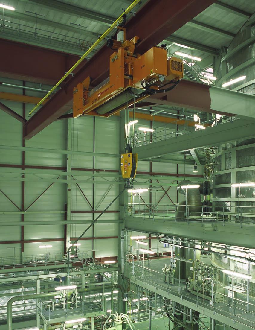
7 General Instructions Application Area This product is intended for the supply of mobile consumers in the rated current range up to 1250 A and voltages up to 690 V / 1000 V. Target applications are hoist/ crane systems, container stacking cranes, steel mill- or STS-cranes and similar applications with one or more mobile units. The insulation materials are resistant to many ingredients used in the industrial environment, depending on concentration and exposure time. All metal parts are available in copper or seawater-resistant aluminum depending on construction type, and should be evaluated in accordance with the general suitability of these basic materials. Before using in critical environmental conditions such as galvanizing plants, pickling plants, compost works and locations with high concentrations of chemicals (e.g. solvents, aromatics, benzols, etc.), please contact us. Layout There are several decisive factors in the selection and layout of conductor rails. One main characteristic is the current load that actually occurs (total current to be expected during operation not to be confused with the installed power or the resulting maximum current) and the resistance values of the system. Here we look at the longest segment between the power feed and the position of the consumer during start-up. The criterion in question is the resulting voltage drop. Depending on the conductor material and cross section, different losses can result for the same length and current. A conductor rail is properly dimensioned from the point of view of voltage drop when the drop lies within the permitted tolerance range, generally 2-5% and at most 10% including the connection feed cable. Conductor rails are classified by their rated current. This corresponds to the maximum continuous current for the conductor rail and is based on the standard parameters of 35 C ambient temperature and 100% duty cycle (according to IEC >_ 10 min ON). If the duty cycle or ambient temperature is lower, higher currents can be transmitted. Further information about the layout of conductor rails and corrections to rated current specifications is listed starting on page 22. Electrical Safety Insulated SinglePowerLine 0813 conductor rails are designed according to applicable international standards and guidelines, meet today's requirements for the safety of a conductor rail and have contact protection compliant with DIN EN (protection class IP 23). They meet the general requirements for classification and evaluation defined in DIN EN part 32 - Electrical requirements for hoisting machines. Conductor rails and rail components have a high level of safety. With contact protection, direct contact between body parts and electrically conducting parts is prevented (finger protection with DIN VDE and EN / NEMA test fingers / 12 mm foreign bodies). The current collectors are also designed finger-safe when engaged in the rails, but in areas where they leave the rails, such as intersections and switch points, they must be additionally protected using power switches, covers or distance. Installations with voltages over 25 V DC and 60 V AC in publically accessible areas must be secured by covers, installation away from accessible areas or other suitable means. Installations in which the insulation characteristics may be reduced by conductive dust or moisture must be installed away from access by people and be marked as high-voltage electrical equipment with warning signs. In areas with high operating voltage (> 690 V) and installations in a highly contaminated environment with conductive dust or moisture, insulators must be used. The single-pole system can be built with any number of poles and extended in a modular manner. Components for the protective conductor are marked in green or green/yellow and may not be used as phase components. Using installed parts and position coding, it is impossible to engage the PE current collector into a phase pole, or to mix phases. We recommend laying out the PE contact redundantly with two current collectors. Mechanical Safety Please note that the layout of conductor rails and current collectors between fixed and moving system parts must maintain a safety spacing of at least 0.5 m to avoid crushing risks, or other safety measures must be taken to prevent this risk. In exposed installation situations, for example over traffic ways, please ask for details. Use of Conductor Rails Conductor rails are classified as components or incomplete machines according to the Machine Directive MRL 2006/42/ EC. The conductor rails of Program 0813 meet current standards and guidelines for the intended use of the components. For installation into the final product, the specifications valid for this product must be taken into consideration and you must proceed in accordance with the Machine Directive or with the guidelines valid for the place of installation. Use outdoors Outdoors, the conductor rail should be protected from environmental influences as much as possible. Use in high humidity and low temperature areas runs the risk of condensation, the formation of frost and ice build-up on the contact surfaces. In installation in this environment, the rails, in particular aluminum rails, must be equipped with an optional rail heater. Our sales department will be glad to assist you with the layout. Approvals The conductor rail product line meets the product parameters required for international use for these products and has been developed in accordance with the existing standards and guidelines in the EU and the important industrial markets. In addition to IEC/EN standard compliance, the product line also has local UL/CSA and GOST-R approvals. 7

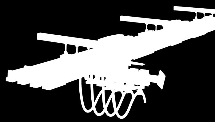
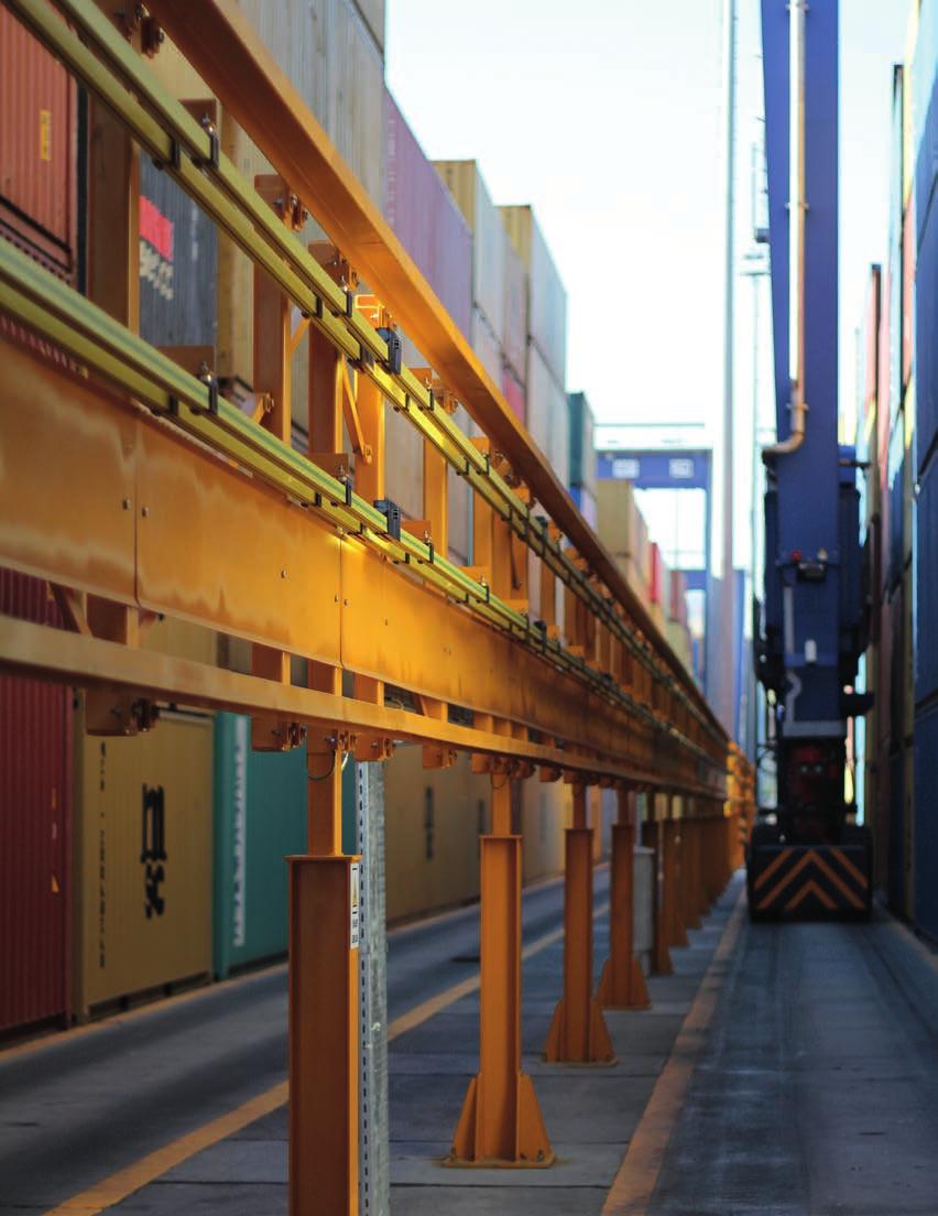
8 System Structure Components and their use Current Collector: Connects to the moving part of the system. Maintains positive contact with the rail as it slides. Available in different sizes as single or dual current collector. Conductor Rails: Stable basic body of conductive material with contact-safe insulated profile. Rail Connectors: Clamping connectors with insulated cap. Can only be removed with a tool (safety requirement). Anchor Clamps: Clamping element for anchoring the system. Forces the rail to expand to either side of the anchor point. Hanger Clamps: Freely rotating and thus self-aligning clip-on holder for quick, safe assembly. Mounting height adjustable. Allows the rail to slide during thermal expansion. Power Feed Connectors: Used instead of a rail connector. Universal connection of single strands with outer diameters of up to 17 mm. Expansion Units (not shown): Changing temperature causes the conductor rail system to expand. To compensate for the expansion in systems over 200 m or systems with multiple fixed points or curves, expansion joints are used. 7 8 End Caps: Rail terminator as protection against accidental contact. Support Arms Pickup Guide (not shown): For areas in which the collector must be driven in or out of the conductor rail system. Air Gap (not shown): For galvanic isolation, for example of segments during maintenance. System Advantages Robust, tried and tested industrial design Safe conductor rail with contact protection (finger-safe design) Designed to national and international standards High availability Expandable Simple installation Optional safety components / functions Rails in safety warning color RAL 1018/1021 CE-compliant design Available with any number of poles Partial compensation for thermal expansion 8


9 System Structure Insulated Conductor Rails The standard product line offers electrolytic copper and aluminum as conductor materials. Copper, with its good conductivity, is the ideal conductor, with restrictions in applications in aggressive or corrosive environments. As a budget-priced alternative, aluminum rails with a stainless steel contact surface are also available. Using a special procedure, stainless steel and seawater-resistant aluminum are firmly joined with no gap, combining the advantages of both materials, that is, good conductivity and low wear, without the disadvantages of other aluminum rails available on the market with stainless steel inserts. The conductor rails consist of the conductive rail body and the protective insulation in a contact-safe design. As insulation material, PVC is used in standard applications For higher ambient temperatures halogen-free PPE+SB is used. 32 Rated length: 5000 mm 42 Color: Safety warning RAL 1018 (PVC) / RAL 1021 (PPE+SB) PH = Phase PE = Potential Earth Aluminum (with stainless steel contact surface) Copper Rated current (100% duty cycle) 500 A 800 A 1000 A 500 A 800 A 1250 A Cu figure 1.6 kg/m 2.86 kg/m 4.76 kg/m Part number Standard insulation for ambient temperatures up to +55 C PH * * * * PE (green color stripes) * * * * Part number Insulation for ambient temperatures up to +85 C PH PE (green color stripes) Short lengths of 1, 2 and 3 m are available upon request for an additional price for cutting costs Part No. for semistandard: length x (length = 1 for 1 m, 2 for 2 m, and 3 for 3 m), lenghts > 6 m on request example 1m: 0813xx-1 x 11 * Standard range Technical Data Rail Length 5000 mm ± 3 mm DC resistance [Ω/1000m] 20 C DC resistance [Ω/1000m] 35 C Impedance [Ω/1000m] 20 C/50Hz Impedance [Ω/1000m] 35 C/50Hz Weight [kg]


10 Hanger Clamps Hanger Clamps M10 52 M10 max Hanger Clamps with Insulators M max max Part No. Designation Weight [kg] * Hanger Clamp galvanized with hex nut * Hanger Clamp galvanized with square nut * Hanger Clamp in stainless steel with hex nut * Hanger Clamp in stainless steel with square nut * Standard range M max Ø Ø Suspension is carried out using freely swivelling clip-on Hanger Clamps that are self-aligning and permit low-friction slipping in case of thermal expansion. Hanger Clamps are available with hex nuts or square nuts for the mounting of Support Arms / C-rail (see installation accessories). Note: - Rated suspension spacing 2.5 m, typically 2.4 to 2.6 m - Max. suspension spacing 2.5 m - Hole drilled for mounting ø 11 mm 10 Part No. Designation Weight [kg] Hanger Clamp galvanized with hex nut * Hanger Clamp galvanized with square nut Hanger Clamp in stainless steel with hex nut * Hanger Clamp in stainless steel with square nut * Standard range
 to protect against corrosion.")
![When mounting clamping screws, use a torque wrench to achieve correct tightening torques. Part No. Designation Weight [kg] 081321-1 Connector for copper rails 500/800 A 1.](/docs-images/75/71951019/images/11-1.jpg "1 081321-2* Connector for aluminum rails Galvanized 1.0 081321-3* Connector for copper rails 1250 A 1.6 081321-4 Connector for aluminum rails 1.")
11 Rail Connectors and Power Feed Connectors Rail Connectors Rails are connected using compact screw connections. The rail connections must have exposed metal on all contact surfaces and be coated with a thin layer of contact grease (Part no ) to protect against corrosion. When mounting clamping screws, use a torque wrench to achieve correct tightening torques. Part No. Designation Weight [kg] Connector for copper rails 500/800 A * Connector for aluminum rails Galvanized * Connector for copper rails 1250 A Connector for aluminum rails Connector for copper rails 1250 A Stainless Steel Connector for copper rails 500/800 A * Contact grease, one 20 g tube (for approx. 200 connection points) * Standard range Power Feed Connectors The power feed uses a power connector; these replace the normal rail connectors. Electrical connection is provided using projecting bolts and notch-type cable Lugs (cable and cable lugs not included; please order separately). Note: - Tightening torque max. 31 Nm - Max. outer cable diameter 25 mm - Use contact grease Part No. Designation Weight [kg] * Power feed connector for aluminum rails 1.0 Galvanized * Power feed connector for copper rails Power feed connector for aluminum rails 1.0 Stainless Steel Power feed connector for copper rails 1.6 * Standard range Notch-type Cable Lugs see page 12 11


12 Anchor Clamps and End Caps Anchor Clamps The rails are fixed in one place with Anchor Clamps and can expand freely from that point out. The fixed point is mainly for single feed applications attached close to the power feed or in the center of the conductor rail system. If multiple fixed points are planned, for example at intersections or curves (natural fixed point), the segment between the fixed points must be decoupled using Expansion Units. Clamps are fastened with a clamping cone on the rail insulator. Part No. Designation Weight [kg] * Anchor Clamp For each fixed point, order two Anchor Clamps per pole * Standard range End Caps End Caps are used as a rail terminator and contact protection and are fastened to the rails using clamping screws. Part No. Designation Weight [kg] * End Cap Stainless Steel (DIN parts) * End Cap for aluminum rails 1000 A * Standard range Notch-type Cable Lug for Power Feed Line d max. 36 Ø 13 Ø b Ø c a 12 Part No. Cross section [mm 2 ] a [mm] b [mm] c [mm] d [mm] Weight [kg/1000] * * * * * * * * * Standard range Material: Copper, tin-plated Order lot size 10 pcs. per size


13 Air Gaps Air Gaps Air Gaps are used for the galvanic isolation of sections, such as maintenance segments that can be supplied with power and turned off separately. For each separation point, two Air Gaps must be mounted at a suitable distance to avoid power carryover through the Current Collectors. Part No. Designation Weight [kg] Air Gap Air Gap for aluminum rails 1000 A
14 Expansion Units Expansion Units bei at 20 To compensate for changes in length due to temperature for systems > 200 m or segments connected between two fixed points such as Pickup Guides on both ends of the segment, or in curves (natural fixed points), expansion elements are needed to absorb the change in length. The expansion element has two expansion points, each of which can absorb 25 mm of expansion. The expansion elements / expansion unit parts are, like the rails, designed as 5 m standard components. Note: The middle part between the two expansion segments must be supported using hanger clamps (not included order separately). When using expansion units, the use of dual Current Collectors is recommended. Expansion Units Standard variant Expansion Units Heat-resistant variant PH (Phase) PE (Potential Earth) PH (Phase) PE (Potential Earth) Weight [kg] For aluminum rails 500 A x 2131* x 2132* x x For aluminum rails 800 A x 2141* x 2142* x x For aluminum rails 1000 A x 2181* x 2182* x x For copper rails 500 A x x x x For copper rails 800 A x x x x For copper rails 1250 A x 2171* x 2172* x x Design: Fastening and DIN parts in stainless steel rated length 5000 mm (16.40 feet). Hanger Clamps in the middle segment not included in scope of delivery please order separately! Delivery: completely pre-assembled at the factory. Adjustment of the two expansion gaps according to the table on page 15, depending on temperature values. * Standard range Layout notes Changes in ambient temperature and intrinsic heating cause the conductor rails and the insulation to expand differently. The SinglePowerLine 0813 conductor rail system has a partial thermal expansion system. The difference in thermal expansion between the insulation and the rails is compensated for in each individual rail. For this reason, the insulation profile is specified shorter than the rail and the compensation takes place in the area of the connector caps without influencing the contact guard. By using self-aligning, rotating Hanger Clamps, the rail line can expand without friction and thus be laid out up to a length of 200 m without additional Expansion Units. If the power feed is in the middle with a fixed point at the power feed, installations of up to 200 m can be laid out without expansion elements by allowing the segment to expand freely to each side for 100 m from the fixed point. For installations of greater length, multiple fixed points such as Pickup Guides or curves that also have a fixed position due to a fixed point or mechanical attachment, expansion joints must be used to absorb the changes in length. Pickup Guides and curves are to be considered as fixing points. 14
15 Expansion Units Expansion Units Ambient temperature during installation [ C] t max Air gap [mm] t min Legend: t min lowest temperature that occurs in the application t max highest possible working temperature in the application 1. Draw a connecting line from t min to t max. 2. Draw the ambient temperature during installation as a horizontal line. 3. Draw a vertical line down from the point of intersection of these two lines, and read off the air gap to be used during installation. Examples: 1 Temperature range: from -15 C to +85 C Ambient temperature during installation: +30 C Air Gap: 25 mm 2 Temperature range: from 0 C bis +60 C Ambient temperature during installation: +10 C Air Gap: 37 mm Number of Expansion Units for systems over 200 m in length For rail conductor installations over 200 m in length, Expansion Units must be installed at specific intervals, as shown in Diagram 3. In complicated curves and other special installations, as well as for fixed point arrangements at the end of the system, special intervals must be used. Please contact us. Number of Expansion Units Intermediate length a Material Al Cu Al Cu Al Cu Al Cu Al Cu Al Cu Total length of the conductor rail [m] Al = Aluminum, Cu = Copper t ges t ges = t U + t sw L 200 m Diagram 3 t U = Temperature range of the ambient temperature t sw = Temperature increase due to electric current (electrical thermal load) Recommended values for t sw : 10 C up to 40% duty cycle 20 C up to 65% duty cycle 30 C up to 100% duty cycle For longer systems than those in the table above, use: L = number of Expansion Units a 5 DV 4 DV 3 DV 100 m 2 DV a 1 DV FP (Anchor Clamp) DV (Expansion Unit) a (intermediate length for one Expansion Unit) L (total length of system) Note: Intersection Pickup Guides and curves are fixed points, so these areas must also be taken into consideration when laying out the system. 2 DV ET (Pickup Guide) 100 m 15


16 Pickup Guides for Intersections For areas in which the collector must be driven in or out of the conductor rail system, Pickup Guides are used in combination with Current Collectors provided for this purpose. The speed for Pickup Guide entry must not exceed 80 m/min and that Pickup Guides must be considered wearing parts. Installation tolerances must be taken into consideration. Simultaneous alignment gaps with maximum tolerances in the X and Y directions are not permitted M , a 20 b Dimensions [mm] Number of poles a b The Pickup Guide centers the Current Collector with a maximum lateral and vertical alignment tolerance of ±25 mm. - Settings of less than ±10 mm are recommended. - In installations with Pickup Guides, a corresponding number of Current Collectors must be available, and mounted in intervals that ensure that just the necessary number of Current Collectors needed for momentary power requirements are in use. The user must ensure that the Current Collectors between the Pickup Guides are disconnected from power or are protected against accidental contact. Order No. Type of fastening elements: stainless steel Weight [kg] pole Pickup Guide pole Pickup Guide pole Pickup Guide pole Pickup Guide pole Pickup Guide for Aluminum 1000 A 1-pole Pickup Guide pole Pickup Guide pole Pickup Guide pole Pickup Guide 4.17 Installation note The middle distance between two conductors is 80 mm. This is reduced to 65 mm using the last Hanger Clamp before the Pickup Guide in order to ensure that the Current Collector enters the Pickup Guide precisely. The Pickup Guide is delivered complete with End Caps. The End Caps are pushed onto the rails with a soft-head hammer until they hit the end stops. The clamping screws are then tightened firmly. Hanger Clamp spacing for installations with Pickup Guides pole Pickup Guide Please note also the instructions for mounting the PE Current Collector for installations with Pickup Guides.
17 17

 Installation note The user must ensure that the Current Collector's center line is exactly aligned with the center line of the conductor rail during installation, and that the specified")
18 Current Collectors Current Collectors 250 A ca Technical data Max. current capacity 250 A (for aluminum rails in standstill mode at 100% duty cycle: 125 A) Max. travel speed 600 m/min; higher travel speeds upon request Pressing force 28 N Lateral deviation ± 100 mm Working stroke in insertion direction ± 40 mm Connection cable 70 mm 2, 1.5 m long, high-flexibility; longer connection cable available upon request Distance between the extension arm axis 125 mm (important functional dimension) and contact surface of the rail (SAP CONFIG ) Installation note The user must ensure that the Current Collector's center line is exactly aligned with the center line of the conductor rail during installation, and that the specified installation spacing between the extension arm axis and the contact surface of the rail is being observed (see installation examples on page 27). The connection cables must be highly flexible to ensure free movement of the Current Collectors and be secured with the cable binder on the Current Collector in such a way that no tension or torsion forces are transmitted to the Current Collector head. Designation Fastening elements galvanized PH (Phase) Fastening elements in stainless steel Part No. Fastening elements galvanized PE (Potential Earth) Fastening elements in stainless steel Weight [kg] Current collector 250 A with vertical insertion * * * * Current collector 250 A with horizontal insertion Current collector 250 A with vertical insertion for intersection 1) with Pickup Guides ) Current Collectors for intersections are used if the path of the conductor rail installation is interrupted by branch tracks, crossing beams, etc. These Current Collectors are equipped with a middle centering device and are used with Pickup Guides. * Standard range (SAP KONFIG 08130X-PXL) Installation Examples horizontal/vertical see page 27 18

 Installation note The user must ensure that the Current Collector's center line is exactly aligned with the center line of the conductor rail during installation, and that the specified")
19 Current Collectors Dual Current Collectors 500 A ca Technical data Max. current capacity 500 A (for aluminum rails in standstill mode at 100% duty cycle: 250 A) Max. travel speed 600 m/min; higher travel speeds upon request Pressing force 2 x 28 N Lateral deviation ± 100 mm Working stroke in insertion direction ± 40 mm Connection cable 70 mm 2, 1.5 m long, high-flexibility; longer connection cable available upon request Distance between the extension arm axis 125 mm (important functional dimension) and contact surface of the rail (SAP CONFIG ) Installation note The user must ensure that the Current Collector's center line is exactly aligned with the center line of the conductor rail during installation, and that the specified installation spacing between the extension arm axis and the contact surface of the rail is being observed (see installation examples on page 27). The connection cables must be highly flexible to ensure free movement of the Current Collectors and be secured with the cable binder on the Current Collector in such a way that no tension or torsion forces are transmitted to the Current Collector head. Designation Fastening elements galvanized PH (Phase) Fastening elements in stainless steel Part No. Fastening elements galvanized PE (Potential Earth) Fastening elements in stainless steel Weight [kg] Current collector 250 A with vertical insertion x 01* x 11* x 02* x 12* Current collector 250 A with horizontal insertion x x x x Current collector 250 A with vertical insertion for intersection 1) with Pickup Guides x x x x ) Current Collectors for intersections are used if the path of the conductor rail installation is interrupted by branch tracks, crossing beams, etc. These Current Collectors are equipped with a middle centering device and are used with Pickup Guides. * Standard range (SAP KONFIG 08130X-2XPXL) 19
 conductor Current Collectors To comply with safety standards, Current Collectors for PE rails")
 can only be mounted on the outside, since")
20 Current Collectors Installation Instructions Installation of the PE conductor Current Collector for installations without Pickup Guides L1 L2 L3 PE Deflector angle L1 L2 L3 PE Deflector angle Current Collector Shoe No insertion possible Diagram 1 Diagram 2 Non-interchangeability of PE (Potential Earth) conductor Current Collectors To comply with safety standards, Current Collectors for PE rails must be designed in such a way that they are not easily interchangeable with other Current Collectors. When determining the position of the PE conductor, you must take into consideration that the standard PE conductor Current Collector (with deflector angle) can only be mounted on the outside, since the deflector angle is fastened onto the exposed side of the PE conductor Current Collector Shoe. The deflector angle ensures that the PE conductor Current Collector can never come in contact with a phase line (see Diagram 2). Installation of the PE conductor Current Collector for installations with Pickup Guides In installations with intersections, it is impossible to move the standard PE conductor Current Collector (with deflector angle) through the Pickup Guide. Thus the PE conductor Current Collector is used for intersections whose holders are equipped with a bolt for the Towing Arm. This fixes the position of the PE conductor Current Collector by being inserted into a hole drilled into the Towing Arm using the Drilling Jig listed below. This ensures that the PE conductor Current Collector can only be mounted in the place provided for it. Drilling Jig 08-W To comply with regulations and guidelines, installations with Pickup Guides must have a hole drilled into the Towing Arm using Drilling Jig 08-W , which is then used to hold the bolt on the PE conductor Current Collector. Installation note: The phase Current Collectors needed are lined up on the preassembled Towing Arm and adjusted to the conductor rails. The next-to-outside phase Current Collector is used as a stop for the Drilling Jig. The Drilling Jig must be attached so that the drill sleeves point outwards see illustration below. In this position, the mounting spacing is 80 mm. Drill Sleeve Designation Part No. Weight [kg] Drilling Jig 08-W
21 21
22 Dimensioning and Layout of Conductor Rail System The dimensioning and layout of a conductor rail system is done as follows: A: Determine the load current B: Select the rail type C: Check the voltage drop for the selected rail type D: Check of ambient conditions E: Select accessories and Current Collectors A. Determining the load current (total rated current / NG ) To determine the total expected load current, individual currents of the highest draw consumers that can operate simultaneously are added up. If the entire installed power is summed, the rail capacity will be over-specified. To avoid overdimensioning, the individual currents are evaluated for simultaneity. To optimizes the system, it is always wise to consider individual consumers that cannot be operated simultaneously (e.g. a crane's slewing gear can only be operated when the crane trolley is stopped), and then only the consumer (the slewing gear or the trolley) with the higher current consumption is used. If multiple units are installed on a single track, for example three cranes on one crane track, the probability of simultaneous operation in the same load should be used to calculate the current. In practice, the following simple table has proved useful in calculating the total rated current / NG for multiple consumers: Number of cranes I N of the most powerful motor of all the cranes I N * I N of the second most powerful motor of all the cranes I N * I N of the third most powerful motor of all the cranes I N * I N of the fourth most powerful motor of all the cranes I N * According to work with 2 cranes * = For dual drives, use 2 I N B. Rail current capacity depends on duty cycle and ambient temperature The specified rated currents for the conductor rail are based on the definitions in European standards and are relative to an ambient temperature of 35 C and a duty cycle (DC) of 100%. If the duty cycle is shorter, such as might be the case for a crane with finite movement, the rail can conduct higher current than the rated current. Adjusting the rail rated current for shorter duty cycles [A] The load current of the conductor rail can be increased for shorter duty cycles. Note: When comparing the rated currents of rails from different manufacturers, always take into consideration the reference ambient temperature and the duty cycle! Consumptions with 100% duty cycle such as lighting, air conditioning or magnetic grippers must be taken into consideration A Copper rails 1000 A Aluminum rails 800 A Copper rails 800 A Aluminum rails 500 A Copper rails 500 A Aluminum rails 100% DC ^= t 10 min. (according to EN standards) % DC (duty cycle)
23 Dimensioning and Layout If the ambient temperatures differ from the standard value of 35 C, the loads must be adjusted. At lower temperatures, the heat release (convection) is better and the rail can handle higher current loads. At higher temperatures, the release of thermal energy to the surrounding air is slower and the load must therefore be reduced. The corresponding values f A are taken from the following table: Ambient temperature 35 C 40 C 45 C 50 C 55 C 60 C 65 C 70 C 75 C 80 C 85 C Standard insulation Heat-resistant insulation I SCHL G zul = I SCHL G zul 35 C f A Aluminum rails f A Copper rails Aluminum rails f A Copper rails I SCHL = rated current of the conductor rail for the specific ambient temperature C. Calculating the voltage drop After selecting the rail type based on the calculated total current depending on duty cycle and ambient temperature, the voltage drop must be checked. The calculated voltage drop must be under the value specified by the customer. Typical values here are 2-5%, or 10% in exceptional cases. If the voltage drop is too high, the voltage might be too low to all the drives to start. The following formulas are used for the calculation: For direct current U 35 C = 2 I I G R [V] For alternating current U 35 C = 2 I I G Z [V] For three-phase power U 35 C = 3 I I G Z [V] U 35 C = voltage drop at 35 C I G = total current R = resistance of the conductor rail Z = impedance of the conductor rail I = feed length L = conductor rail length [V] [A] [Ω/m] [Ω/m] [m] [m] 1) Note: I G here is the portion of the load current drawn during start-up. This consists of the basic load, like lighting and air conditioners, and the start-up currents of the drives I A. 1) see feed variants For start-up current, the following applies: Three-phase asynchronous drive in direct start I A = I G x 5 to 6 (up to max. 21 kw permitted) I G = total current Slip ring rotor motor I A = I G x 3 to 5 I A = Total current consumption when starting Frequency converter I A = I G x 1.2 to 1.4 The length l is the distance between the power feed and end position of the conductor rail segment on which the consumer is located when starting. If the average ambient temperature is significantly over 35 C, the voltage drop must be calculated using the following formulas: U U = 35 C [V] f V U U % = 100 [%] U N U = voltage drop at higher ambient temperature than 35 C [V] U % = voltage drop at ambient temperature over 35 C [%] U N = rated voltage [V] f V = reduction factor To calculate the value f V, the working temperature must first be calculated. AT = UT + SW = UT + 30 [ C] AT = working temperature [ C] UT = ambient temperature [ C] SW = temperature increase due to current heating [ C] (use a constant +30 C) The value f V is based on the working temperature and the conductor rail selected and should be taken from the table Correction factors for the voltage drop for different ambient temperatures on page 24. U 23
24 Dimensioning and Layout Correction factors for the voltage drop U at different ambient temperatures Ambient temperature 35 C 40 C 45 C 50 C 55 C 60 C 65 C 70 C 75 C 80 C 85 C Working temperature / conductor temperature 65 C 70 C 75 C 80 C 85 C 90 C 95 C 100 C 105 C 110 C 115 C Aluminum rails 500 A Aluminum rails 800 A Standard insulation Aluminum rails 1000 A f V Copper rails 500 A Copper rails 800 A Copper rails 1250 A Aluminum rails 500 A Aluminum rails 800 A Heat-resistant insulation Aluminum rails 1000 A f V Copper rails 500 A Copper rails 800 A Copper rails 1250 A If the voltage drop is too high, then either the number of power feeds must be increased or a larger conductor rail must be selected. Additional power feeds are usually a better technical and commercial alternative than larger conductor rails or costly copper rails. Working temperature: permanent rail temperature occurring at rated current (ambient temperature + electrical thermal heating) Max. working temperature: short-term (t < 30 sec) 125 C (in heat-resistant variant) Possible power feed locations: The power feed arrangement must be appropriate for the specific case, since the voltage drop is calculated with the feed length "l" that falls between the power feed and the end of the conductor rail. The following power feed options are normally used: End power feed Middle power feed I = L/2 I = L L I = L With an end power feed I = L/2 With a middle power feed I = L/4 For power feeds at both ends I = L/6 For two power feeds each L/6 from the ends I = L/10 For a power feed in the middle and L/10 from each end I = L/14 For four power feed points Power feed on both sides I = L/4 L = length of the conductor rail [m] L/6 power feed I = L/6 I = L/6 L L/10 power feed I = L/10 I = L/2 L I = L/10 24 L/14 power feed I = L/14 I = L 5/14 I = L 9/14 L I = L/14
25 System Layout M10 M10 ø 11 mm M10 M10 ca.75 ca.115 ca.135 ca.145 Note: Used outdoors, the conductor rail system must be protected from direct weather exposure as much as possible, for example by installing it under a beam and providing covering the Current Collector (to protect it from snow and ice). Outdoors, insertion of the Current Collector from below is generally preferable to lateral insertion. Also, the use of insulated holders is recommended for outdoor installations. If there is any risk of formation of frost or ice, specify heating conductors in the rail to de-ice the rail and prevent rail damage due to sparking effects on frozen rails (Aluminum rails). ca.180 ca
26 System Layout Layout Schematic and Component Overview Example: 5 m rail max. 200 m without Expansion Unit max. 100 m max. 100 m End Center 5000 Rail length Rail length Rail length Hanger Clamp Hanger Clamp with Fixed Points Rail Connector End Cap Power feed Installation note Regarding the first and the last conductor rail a support distance of 1750 and 250 mm from the beginning resp. the end of the rail is to be provided. Apart from that the support spacing is 2.5 m. The earth collector should always be installed on the outside. The center distance between two conductors can be taken from the table below. Distance between centers of two conductor rails Standard current collector arrangement Offset Current Collector arrangement Current collector arrangement for installations with multi poled Pickup Guides* L1 L2 L3 PE Minimum distance a [mm] * See mounting instructions for Pickup Guides. a a a Example material overview / example order Here is a typical crane conductor rail system that is 57 m in total length, with 4 poles, 800 A, with all accessories, Current Collectors and Support Arms. The required Bill of Materials is listed below. The order quantity should be increased by an assembly reserve for the parts marked with an (x). Part Description Part No. Quantity Needed Conductor Rail Phase 5 m long * Conductor Rail Phase 2 m long * Conductor Rail PE 5 m long * Conductor Rail PE 2 m long * Hanger Clamp (x) Anchor Clamp Rail Connector (x) Power Feed Notch-type Cable Lug 95 mm 2 (x) End Cap (x) Current Collector Phase Current Collector PE Extension Arm Support Arm Girder Clip Mounting Comb Conductix-Wampfler Contact Grease (x) Copper Graphite Shoe (replacement part) (x) Note: to avoid strand breakage due to external force on the Current Collector, the connection cable should be fine-stranded and highly flexible. The transition to the customerprovided fixed cabling should be directly behind the Current Collector in a terminal box provided by the customer. Long connection cables to Current Collectors should be avoided to reduce maintenance problems.


27 Layout Examples Standard Current Collector Layout Horizontal installation of conductor rails / Vertical insertion of Current Collectors Vertical installation of conductor rails / Horizontal insertion of Current Collectors Offset Current Collector Arrangement Vertical and horizontal insertion of Current Collectors a a a , For installations without transfer points the current collectors for vertical and horizontal operation can be stag gered. This way the center distance between two conductor rails is reduced by 10 mm. Distance between centers of two conductor rails Standard current collector arrangement Offset Current Collector arrangement Current collector arrangement for installations with multi poled Pickup Guides* Minimum distance a [mm] * See mounting instructions for Pickup Guides. Installation note Please note that the center line of the current collector is mounted to the center line of the conductor rail. The distance between towing arm and conductor rail must be set according to the dimension indicated in above table and sketches. 27
![f Mounting Accessories Support Arms 40 40 2,5 mm - perforated L1 40 40 ø 9 2.5 2,5 14 40 20 20 L2 Part No. L 1 [mm] L 2 [mm] Material Weight [kg] 020186-0250 250 200 0.625 020186-0315 315 260 0.](/docs-images/75/71951019/images/28-1.jpg "785 020186-0400* 400 340 1.000 Galvanized steel 020186-0500* 500 340 1.250 020186-0630* 630 340 1.575 020186-0800 800 340 2.000 * Standard range Permissible load for Support Arms 40 x 40 mm F I [m] 0.")
28 f Mounting Accessories Support Arms ,5 mm - perforated L ø , L2 Part No. L 1 [mm] L 2 [mm] Material Weight [kg] * Galvanized steel * * * Standard range Permissible load for Support Arms 40 x 40 mm F I [m] F [dan]* I f [cm] * Calculated with σ = 140 N/mm 2 voltage f = associated max. deflection 28

![Description Suitable for Support Arm Weight [kg] 020282 Galvanized steel 020186 1.](/docs-images/75/71951019/images/29-1.jpg "000 Holder for Support Arms 40 40 2,5 125 41,3 41.3 4 12 x 45 41 Part No.")
29 Mounting Accessories Holder for Support Arms ,5 for screw mounting with 2-holed connector plate ø , Part No. Description Suitable for Support Arm Weight [kg] Galvanized steel Holder for Support Arms , , x Part No. Description Suitable for Support Arm Weight [kg] Unplated steel with galvanized hardware
30 Mounting Accessories Girder Clips, clamping thickness 4-20 mm 60 M8 Part No. Description Weight [kg] * Galvanized steel Stainless steel (V4A) * Standard range Clamping thickness s [mm] Installation height h [mm] s 50 h Girder Clips, clamping thickness mm 70 M8 Part No. Description Weight [kg] Galvanized steel Stainless steel (V4A) s 8 Clamping thickness s [mm] Installation height h [mm] h Girder Clips, non-twistable, clamping thickness 6-25 mm M8 8 Part No. Description Weight [kg] Galvanized steel s Clamping thickness s [mm] 6-25 Installation height h [mm] h 30 30
![Mounting Accessories Towing Arms L 6 40 100 80 Ø11 Part No. Description L [mm] Weight [kg] 020197-400 400 2.0 020197-630* Galvanized steel 630 2.](/docs-images/75/71951019/images/31-0.jpg "5 020197-800 800 3.0 * Standard range End Caps a c h s b d Part No.")
![For C-rails Description a [mm] b [mm] c [mm] d [mm] s [mm] h [mm] Weight [kg] 020662-30 023200 30 32 27 29 4 18 0.](/docs-images/75/71951019/images/31-1.jpg "005 Plastic 020662-31 023201 30 30 28 28 5 16 0.")
 Cantilever strength > 350 dan Ambient temperature -30 C to +85 C Ø 50 d 15 36 15 l1 15 d Ø 25 d Ø25 Ø")
31 Mounting Accessories Towing Arms L Ø11 Part No. Description L [mm] Weight [kg] * Galvanized steel * Standard range End Caps a c h s b d Part No. For C-rails Description a [mm] b [mm] c [mm] d [mm] s [mm] h [mm] Weight [kg] Plastic Insulators Insulators for indoor applications with high contamination and/or applications outdoors, up to 1000 V rated voltage d Creepage distance 62 mm Leakage current resistance KC 575 V (CTI) Cantilever strength > 350 dan Ambient temperature -30 C to +85 C Ø 50 d l1 15 d Ø 25 d Ø25 Ø 50 Part No. Hardware d I 1 [mm] Weight [kg] x 10 Inner threading on both ends M10 / M x 10 Threaded bolts, galvanized M10 / M x 10 Threaded bolts, stainless steel M10 / M
![Mounting Accessories Junction Box for Power Feed, with Fittings, Clamps and Accessories 110 Part No. Designation Weight [kg] 080102-3 Junction Box with 3 poles 0.](/docs-images/75/71951019/images/32-0.jpg "300 080102-4 Junction Box with 4 poles 0.310 080102-5 Junction Box with 5 poles 0.320 75 56,5 56.5 Junction Box for Power Feed, with Fittings, Clamps and Accessories 110 Part No.")
![Designation Weight [kg] 080103-3 Junction Box with 3 poles 0.290 080103-4 Junction Box with 4 poles 0.300 080103-5 Junction Box with 5 poles 0.310 75 56,5 56.](/docs-images/75/71951019/images/32-1.jpg "5 Mounting Comb 081046 For setting the rail holder spacing while mounting the Support Arms Part No. Designation Weight [kg] 081046* Mounting Comb 0.")
32 Mounting Accessories Junction Box for Power Feed, with Fittings, Clamps and Accessories 110 Part No. Designation Weight [kg] Junction Box with 3 poles Junction Box with 4 poles Junction Box with 5 poles , Junction Box for Power Feed, with Fittings, Clamps and Accessories 110 Part No. Designation Weight [kg] Junction Box with 3 poles Junction Box with 4 poles Junction Box with 5 poles , Mounting Comb For setting the rail holder spacing while mounting the Support Arms Part No. Designation Weight [kg] * Mounting Comb * Standard range 4 x 70 (= 280) x 80 (= 320)
.")
 Part No. Designation Weight [kg] 080021* Contact Grease 0.")
33 Tools and Assembly Accessories Grounding- and Short-circuit Device Protective device during service and maintenance work on the conductor rail Part No. Designation Weight [kg] 08-V * Grounding Device 813 with one pole 2.2 * Standard range Note: Several devices have to be used, depending on the number of poles (all live rails + ground rail). The modular design of the Devices allows for any number of them to be connected. Four Devices have to be used for a 3-phase system (1 x PE + 3 x PH = 4). Contact Grease for Connection Points (Aluminum rails) Part No. Designation Weight [kg] * Contact Grease * Standard range Application: Use contact grease to avoid corrosion at contact points. A thin film is applied with finger or brush to the faces of the conductor rail and the clamping area of the connectors. One tube will last for about 200 connection points. 33

. Insulator is included. Replacement Parts for Current Collectors Copper Graphite Shoe Plastic Insulator Contact Sheet Collector Head Part No.")
34 Replacement Parts Replacement Copper Graphite Shoes Current Collector Heads Copper Graphite Shoe 160 Plastic Insulator x 63 The copper graphite shoe is protected by a plastic insulator, so that accidental contact with live parts of the engaged Current Collector is not possible. Part No. Designation Ampere [A] Wearing Height X Weight [kg] * Copper graphite shoe * Standard range Installation note: When replacing the Copper graphite shoe, it is not necessary to remove the collector head because the shoe is designed as a plug-in contact (not a screw contact). Insulator is included. Replacement Parts for Current Collectors Copper Graphite Shoe Plastic Insulator Contact Sheet Collector Head Part No. Designation Weight [kg] 08-A * Collector Head PE A * Collector Head PH 0.1 Connection Repair Set, including: 1 Contact Sheet (1847) 1 Tubular Cable Lug (27633) 1 Heat Shrinkable Tubing black, 55 mm (25662) 10 Heat Shrinkable Tubing yellow/ 08-K green, 50 mm ( ) Hexagonal Screw DIN933 M8 x 20 (998) 1 Lock-nut DIN985-M08-A4 (581) 1 Washer DIN125-A8, 4-A4 (686) Connection Repair Set Connecting Cable Connecting Cable (pre-assembled) on request * Standard range (SAP KONFIG 08130X-K0PF-PXL) 34 Heat Shrinkable Tubing (yellow/green)

35 Conductix-Wampfler the complete program Other Products from Conductix-Wampfler The products described in the this catalog represent a few of the products from the broad spectrum of Conductix-Wampfler components and systems for the transfer of energy, data, gases, and fluids. The solutions we deliver for your applications are based on your specific requirements. In many cases, a combination of several different Conductix-Wampfler products are needed to fill the application. You can count on all of Conductix-Wampfler s business units for hands-on engineering support - coupled with the perfect solution to meet your energy management and control needs. Motor driven cable reels Motor driven reels by Conductix- Wampfler are the perfect solution for managing long lengths of heavy cable and hoses in very demanding industrial applications. Monospiral, level wind, and random wind spools. Slip ring assemblies Whenever powered machinery needs to rotate 360 0, field proven slip ring assemblies by Conductix-Wampfler can flawlessly transfer energy and data. Here, everything revolves around flexibility and reliability. Conductor bar Whether they are enclosed conductor rails, expandable single-pole bar systems, or high amperage bar for demanding steel mill use up to 6000 amps. Conductix-Wampfler s conductor bar is the proven solution to reliably move people and material. Spring driven cable reels We have 60 years experience and trusted brands such as Insul-8, Wampfler, and IER. We offer small cord reels all the way to large multi-motor units, a wide range of accessories, and hazardous location reels. Cable Festoon systems It s hard to imagine Conductix- Wampfler cable trolleys not being used in virtually every industrial application. They are reliable and robust and available in an enormous variety of sizes and models. Push Button Pendants Our ergonomic pendants are ideally suited for industrial control applications. They are available in a wide range of configurations for overhead cranes and other machinery. Radio remote controls Safe, secure, and reliable radios use the latest in microprocessor technology. Available in several models for overhead crane control and other types of machinery. Inductive Power Transfer IPT The contact-less system for transferring energy and data. For all tasks that depend on high speeds and absolute resistance to wear. Energy guiding chains The Jack of all Trades when it comes to managing energy and data cables and air and fluid hoses. A wide range of energy guiding chains are available for many industrial applications. Air hoists and balancers ENDO Air hoists accurately place delicate loads and continuously vary the speed for precise positioning. They run cool in continuous operations. Bumpers Conductix-Wampfler offers a complete range of bumpers for the auto industry, cranes, and heavy machinery. These include rubber, rubber/metal, and cellular types. Spring balancers and retractors ENDO spring balancers by Conductix- Wampfler are rugged, reliable high-precision positioning devices that reduce operator fatigue and assist with accurate tool placement.
Insulated Conductor Rail SinglePowerLine Program 0812
 Insulated Conductor Rail SinglePowerLine Program 0812 Table of Contents System Description 5 Technical Data 6 General Instructions 7 System Structure 8 Components and their use....8 Insulated Conductor
Insulated Conductor Rail SinglePowerLine Program 0812
 Insulated Conductor Rail SinglePowerLine Program 0812 2 Table of Contents System Description 5 Technical Data 6 General Instructions 7 System Structure 8 Components and their use... 8 Insulated Conductor
1 Product Description System Layout Safety Instructions Intended Use Installation... 3
 Order Number 0812xx- Contents 1 Product Description... 2 2 System Layout... 2 3 Safety Instructions... 3 4 Intended Use... 3 5 Installation... 3 5.1 Hanger Clamp... 3 5.2 Cutting of Conductor Rail... 4
Multipole Conductor Rail MultiLine Program 0831
 Multipole Conductor Rail MultiLine Program 0831 Contents Description / Technical Data Description....2 Technical Data....3 Conductor Rails Rails complete with pre-mounted Connector...4 Power Feeds....5
1 Product Description System Layout Safety Instructions Intended Use Installation... 3
 Part Number 0812xx- Contents 1 Product Description... 2 2 System Layout... 2 3 Safety Instructions... 3 4 Intended Use... 3 5 Installation... 3 5.1 Hanger Clamp... 3 5.2 Cutting of Conductor Rail... 4
Energy Supply Systems
 Energy Supply Systems MULTIPOLE CONDUCTOR RAIL 831 10-125 amps KAT0831-0001b-E 13 pole multipole conductor rail in 33 package distribution centres of the postal service (Post AG) 9 pole multipole conductor
Energy Supply Systems
 Energy Supply Systems SINGLE POLE INSULATED CONDUCTOR RAIL 815 100 amps KAT0815-0001b-E Conductor rail system in a high bay storage Slip ring with conductor rail system in a stretch-foil packing machine
1 Product Description Check of the supplied Parts Notes Intended Use Current Collector... 3
 Order number 0813xx-... Contents 1 Product Description... 2 2 Check of the supplied Parts... 2 3 Notes... 2 4 Intended Use... 2 5 Current Collector... 3 6 Installation Sequence... 3 7 Pickup Guide... 7
Multipole Conductor Rail MultiLine Program 0831
 Multipole Conductor Rail MultiLine Program 0831 ProShell - the modular carrier profile as a system supplement for program 0812 and 0831 ProShell catalog KAT0800-0003-E available for download at www.conductix.com
4 pole insulated conductor rails UNILIFT-ULA 35A, 50A, 80A, 100A
 2 Table of contents General information... 4 Elements of the conductor rail supply line... 4 Innovative connection method... 5 Technical properties... 6 Construction of the line section... 6 Line section...
4 pole insulated conductor rails ULA 35A, 50A, 80A, 100A
 Table of contents General information... 3 Elements of the conductor rail supply line... 3 Innovative connection method... 3 Technical properties... Construction of the line section... Line section...
4 pole insulated conductor rails ULA 35A, 50A, 80A, 100A
 Table of contents General information... 3 Elements of the conductor rail supply line... 3 Innovative connection method... 3 Technical properties... Construction of the line section... Line section...
Conductor Rail System for Shuttles MultiLine Program 0835
 MultiLine Program 0835 Table of Contents General Information 5 System Advantages 5 Main Features at a Glance 6 Technical Data 7 Conductor Rail 8 End Segment (End Power Feed) 8 Rail Connector 9 Standard
Heavy-Duty Conductor Rail CopperHead
 Heavy-Duty Conductor Rail CopperHead Table of Contents CopperHead Conductor Systems 4 Heavy-Duty Conductor Rails...4 Some Advantages of CopperHead Rail Systems...4 Product Pre-Selection...4 Technical
1 Product Description Check of the supplied Parts Notes Intended Use Current Collector... 3
 Part number 0813xx-... Contents 1 Product Description... 2 2 Check of the supplied Parts... 2 3 Notes... 2 4 Intended Use... 2 5 Current Collector... 3 6 Installation Sequence... 3 7 Pickup Guide... 6
Conductor Bar Series 812
 Conductor Bar Series 812 Contents Page 1 Completeness of the delivered parts... 1 2 Hints... 2 3 Installation... 2 4 Maintenance... 6 5 Photos of relevant system parts... 8 In addition to other advantages,
Insulated Conductor Rail SingleFlexLine Program 0811
 Insulated Conductor Rail SingleFlexLine Program 0811 Contents System Description 5 Technical Data 6 System Components and Standards 7 Components and their use...7 Project Planning 9 Technical notes and
ProEMS Insulated Conductor Rail for Electrified Monorail Systems Program 0815
 ProEMS Insulated Conductor Rail for Electrified Monorail Systems Program 0815 Supplementary Documents Installation instructions: MV0815-0007-EN Installation Instructions for Conductor Rail System 0815
ProEMS Insulated Conductor Rail for Electrified Monorail Systems Program 0815
 ProEMS Insulated Conductor Rail for Electrified Monorail Systems Program 0815 Supplementary Documents Installation instructions: MV0815-0007-EN Installation Instructions for Conductor Rail System 0815
GENERAL INDEX TR60. 6 YELLOW LINE Continuous Conductors. Max 5 Poles. 8 BLUE LINE Pre-Mounted Conductors TR85H5P. YELLOW LINE Continuous Conductors
 2 Automation - Lift - Handling System GENERAL INDEX 2 DESCRIPTION 3 BUSBAR LINE VERSIONS LINE TYPE / AMPERAGE COVERAGE 5 TR60 40 A 50 A 60 A 70 A 100 A 140 A 160 A 200 A 320 A 6 YELLOW LINE Continuous
Conductor Bar Series 831
 Conductor Bar Series 831 1 MV0831-0021b-E CONDUCTOR BAR 831 MANUAL 1 1. Completeness of the delivered parts Please check first, if the individual parts are completely delivered (see Photos on page 7 and
Conductor Rail System for Shuttles MultiLine Program 0835
 MultiLine Program 0835 Table of Contents General Information 5 System Advantages 5 Main Features at a Glance 6 Technical Data 7 Conductor Rail 8 End Segment (End Power Feed) 8 Rail Connector 9 Standard
FABA. Standard Components. Conductor Bar System. publication #FABASC-04 1/1/04 Part Number: Copyright 2003 Electromotive Systems
 FABA Conductor Bar System Standard Components publication #FABASC-04 1/1/04 Part Number: 000-2201 Copyright 2003 Electromotive Systems Table of Contents Section IS 100 A - Introduction General Information
General notes. Operating conditions
 1 General notes Wöhner busbar systems and components are the result of expert development based on many years of experience. They have been exhaustively tested and hold many approvals. The correct selection
ACI Hoist & Crane. Festoon System. 689 S.W. 7th Terrace Dania, FL (954) Fax (954) Toll Free A-HOIST ( )
 Fax (954) Toll Free A-HOIST ( )") ACI Hoist & Crane Festoon System 689 S.W. 7th Terrace Dania, FL 33004 (954) 921-1171 Fax (954) 921-7117 Toll Free 1-888-4-A-HOIST (1-888-424-6478) www.acihoist.com 2 Standard Duty C-Track Index 1. General
ACI Hoist & Crane Festoon System 689 S.W. 7th Terrace Dania, FL 33004 (954) 921-1171 Fax (954) 921-7117 Toll Free 1-888-4-A-HOIST (1-888-424-6478) www.acihoist.com 2 Standard Duty C-Track Index 1. General
Technical data. DKK compact conductor lines engb IS eps
 Technical data DKK compact conductor lines 4146644.eps 10910 engb 0 540 44 714 IS 9 Contents 1 Technical information Straight sections 4 Curved sections 5 4 Powerfeeds 6 5 Ramp sections, expansion joints
Conductor Bar Safe-Lec 2 Hevi-Bar II
 Conductor Bar Safe-Lec 2 Hevi-Bar II Contents Safe-Lec 2 and Hevi-Bar II Overview 3 Conductor Bar Summary Chart 4 Quick Quote Software 5 Quotations Data Sheet 6-7 Safe-Lec 2 8-33 Safe-Lec 2 System Components
Product Overview Conductor Rails
 Product Overview Conductor Rails The simple solution! SingleFlexLine 0811 on an electrified monorail system in a brewery Insulated conductor rails are one of the most widely used systems for the transmission
Cable Trolleys for C-Rails Program
 Cable Trolleys for C-Rails Program 02 0 0260 Contents C-Rail and Accessories Program 02 C-Rail x... 4 Track Coupler... 4 End Stops... 4 Track Support Brackets... 4 Support Arm and Girder Clip... Brackets...
Conductor Bar Safe-Lec 2 Hevi-Bar II
 Conductor Bar Safe-Lec 2 Hevi-Bar II Contents Safe-Lec 2 and Hevi-Bar II Overview 3 Conductor Bar Summary Chart 4 Quick Quote Software 5 Quotations Data Sheet 6-7 Safe-Lec 2 8-33 Safe-Lec 2 System Components
Product Overview Festoon-Systems for I-Beams
 Product Overview Festoon-Systems for I-Beams 2 Conductix-Wampfler Festoon-Systems Count on it! On the go! Cable trolley system program 0350 on a steel mill overhead bridge crane We move your business:
INTRODUCTION. The plug-in connection on the cables and lightning arrestors, allows for easy installation and replacement.
 INTRODUCTION The Power Systems 44 kv MiniSub TM is the most compact system at this voltage available. Utilizing a deadfront termination and lightning arrestor setup, it eliminates the line top or side
Conductor Bar Safe-Lec 2 Hevi-Bar II
 Conductor Bar Safe-Lec 2 Hevi-Bar II Contents 2 Safe-Lec 2 and Hevi-Bar II Overview 3 Conductor Bar Summary Chart 4 Quick Quote Software 5 Quotations Data Sheet 6-7 Safe-Lec 2 8-33 Safe-Lec 2 System Components
Ball Rail Systems RE / The Drive & Control Company
 Ball Rail Systems RE 82 202/2002-12 The Drive & Control Company Rexroth Linear Motion Technology Ball Rail Systems Roller Rail Systems Standard Ball Rail Systems Super Ball Rail Systems Ball Rail Systems
Moisture-proof cable branch boxes Ceiling distribution boxes Lamp suspension boxes Wall boxes Concrete wall boxes and accessories
 Branch and lustre terminals Apparatus and light terminals Porcelain terminals Screwless terminals Flat plug terminals Flat plug branch terminals Mains branch terminals Connection terminals Earthed wire
4-Ductor Insulated conductor bar
 Darwinstraat 10 4-Ductor AKAPP 4-Ductor current supply system compact, reliable and safe! AKAPP 4-Ductor is a compact, reliable and safe current supply system for cranes, hoists, monorail systems, conveyor
ALINOX INSULATED CONDUCTOR RAIL FOR ELECTRICAL FEEDING OF CRANES
 ALINOX INSULATED CONDUCTOR RAIL FOR ELECTRICAL FEEDING OF CRANES 2 ALINOX INSULATED CONDUCTOR RAIL Features, advantages and benefit The insulated conductor rail system ALINOX is the most suitable solution
Product Overview Compressed Air and Electric Supply
 Product Overview Compressed Air and Electric Supply Solutions from a single source! Solutions are born as ideas and implemented through products. Conductix-Wampfler s handling systems can be found in
RockStar HighPower. Contents. RockStar HighPower Introduction C.2 C.1
 ontents Introduction.2 HighPower 250 A.4 4000 V 250 A 1 4 poles HighPower 550 A.10 4000 V 550 A 1 3 poles.1 Introduction Uncompromising power in clever and safe packaging. The modular high-current connector
Page. Circuit-Breakers M4 2 for motor protection. Auxiliary contacts 3 Signalling switch Auxiliary releases
 Circuit Breakers M4 Page Circuit-Breakers M4 2 for motor protection Auxiliary contacts 3 Signalling switch Auxiliary releases Insulated 3-pole busbar system 4 Terminal block DIN-rail adapters 5 Busbar
MR - MEDIUM RATING A
 88 MR - MEDIUM RATING 160-1000A SECTION CONTENTS 90 General features 96 Advantages 100 Illustrated contents MR MEDIUM RATING 102 Trunking components 110 Feed units and end covers 113 Tap-off boxes 118
20 HUBER+SUHNER RADOX SOLAR
 All our cables fully comply with the European directives 76/769/EWG, 2003/11/EG, 2000/53/EG, 2003/53/EG and 2002/95/EG (RoHS) and the requirements of REACH Nr. EC1907/2006. 20 RADOX SOLAR cables RADOX
POWER BAR SYSTEM ECONOMICAL ENCLOSED CONDUCTOR SYSTEM FOR MOBILE EQUIPMENT M O B I L E E L E C T R I F I C A T I O N
 A e r o B A R POWER BAR SYSTEM ECONOMICAL ENCLOSED CONDUCTOR SYSTEM FOR MOBILE EQUIPMENT M O B I L E E L E C T R I F I C A T I O N AeroBAR Enclosed Conductor Bar System AeroBAR provides many of the advantages
Electromotive Systems ELECTROBAR ELITE Conductor Bar System
 Electromotive Systems ELECTROBAR ELITE Conductor Bar System ELECTROMOTIVE SYSTEMS ELECTROBAR ELITE ENCLOSED CONDUCTOR BAR SYSTEMS Magnetek s Electromotive Systems division proudly offers ELECTROBAR Elite,
RE / STAR Tolerance Rings STAR Ball Knobs, Knob and Lever Type Handles
 RE 2 970/.99 STAR Tolerance Rings STAR Ball Knobs, Knob and Lever Type Handles STAR Tolerance Rings Product Overview Tolerance rings are made of hard, embossed spring steel strip and belong to the class
Pro-Ductor Insulated flat conductor bar for 4, 7 or 10 conductors
 Wabtec Netherlands B.V. Darwinstraat 10 NL 6718 XR Ede The Netherlands Flexible with energy! Phone +31 (0)342 403900 Fax +31 (0)342 403912 Email info@akapp.com URL www.akapp.com Pro-Ductor Insulated flat
- 1 - General ordering data Order No
 General ordering data Order No. 1748280000 Part designation B2L 3.5/28 F SN SW Version EAN 4032248156535 Qty. 20 pc(s). PCB plug-in connector, Female connectors, Tension clamp connection, Clamping range,
Fuse switch disconnectors
 SWITCHGEAR RBK Fuse switch disconnectors intended for distribution of electricity and protection of electrical equipment against short-circuits and overloads, with industrial fuse links ENERGY SAFELY SWITCHED
Cable Festoon Systems. C-Track Stretch Wire Rope
 Cable Festoon Systems C-Track Stretch Wire Rope Contents OVERVIEW 3 Festoon Specification Data Sheets 4-5 "Quick Quote Web" Software 6 C-Track Festoon Configurations 7 Flat Cable and Connectors PVC Flat
INSULATED CONDUCTOR SYSTEMS U 20 U 30 U 40
 INSULATED CONDUCTOR SYSTEMS U 20 U 30 U 40 INSULATED CONDUCTORS U 20 U 30 U 40 INDEX U 20 U 30 U 40 Page Page Page Basic description 4 4 4 Selection of conductors 5-10 5-10 5-10 Conductors 11 24 34, 35
Empty enclosures IEC 62208
 374 www.hensel-electric.de/en in accordance with for customized solutions and individual applications for example for low-voltage switchgear and controlgear assemblies i n accordance with the IEC 61439-series
Conductor: plain wire, fine stranding as per VDE 0295 class 6 from 50 mm² fine stranding according to VDE 0295 class 5
 Semoflex DRUM Description Application In dry and damp rooms, explosive security areas and also outdoors for heavy-duty units such as hoisting gears, transportation systems, motorized cable reels, rail
Servo solenoid valves with positive overlap and on-board electronics
 Servo solenoid valves with positive overlap and on-board electronics RE 29089/01.05 1/22 Replaces: 05.04 Type 4WRLE 10...35, symbols E./W. Nominal size 10, 16, 25, 35 Unit series 3X Maximum working pressure
Operating Instructions
 Operating Instructions Terminal Box > 8150/1 > 8150/2 Contents 1 Contents 1 Contents...2 2 General Information...2 2.1 Manufacturer...2 2.2 Operating Instructions Information...2 3 Intended Use...2 4 Safety
Technical data/component parts
 Technical data/component parts Demag pillar and wall-mounted slewing jib cranes 191214 en GB 203 814 44 714 IS 132 Manufacturer Terex MHPS GmbH Forststrasse 16 40597 Düsseldorf, Germany www.demagcranes.com
IEC Low Voltage General Purpose Protection
 , 6A, 0/400VAC (/440VAC) Complying with DIN VDE 0660 Part 07 EN / IEC 60947- DIN VDE 066 Part IEC 6069- DIN VDE 068 DIN VDE 4880 The D0-LINOCUR is a combination of switch-disconnector-fuse and NEOZED 6
The GK units differ from the LK units in that the springs of the GK units have a spring eye at the front.
 01 09 Installation guidelines Mechanical suspension units GK LK GN0032-0 Mechanical suspension units GK LK The GK units differ from the LK units in that the springs of the GK units have a spring eye at
Compressed Air and Electric Supply System Program C40
 Compressed Air and Electric Supply System Program C40 Table of Contents Overview 4 Product Description...4 System Overview....4 Rail Components 5 General Information...5 Load Diagram....5 Rail Couplers....6
INDUSTRIAL PLUGS. FIND ALL INFORMATION ON OUR WEBSITE: marechal.com. Dimensions and certificates
 INDUSTRIAL PLUGS A range from 16 A to 600 A 1000 V. Automatic watertightness from IP44 to 66/67. From -40 to +240 C. GRP or metal casing. Reliable & compact. FIND ALL INFORMATION ON OUR WEBSITE: marechal.com
Installation and Operational Instructions for ROBATIC -clutch Type and Type Sizes 3 9
 Please read the Operational Instructions carefully and follow them accordingly! Ignoring these Instructions may lead to malfunctions or to clutch failure, resulting in damage to other parts. Contents:
COMPACT CONDUCTOR SYSTEMS VKS 10
 COMPACT CONDUCTOR SYSTEMS VKS 10 POWERAIL ENCLOSED CONDUCTORS VKS 10 CONTENTS Page General 2, 3 Planning guide 4 Application photos 5 Technical data, standard sections 6, 7 Curved sections and jointing
Series T is Ideal for:
 Series T SAF-T-BAR Series T is Ideal for: Light Rail Systems Automated Storage and Retrieval Systems Conveyors Indoor, Dry Locations Small cranes, monorails, hoists Moving cameras and instruments Other
Spring Cable Reels EXEL
 Spring Cable Reels EXEL Conductix - Wampfler designs and manufactures high-performance electrification systems for mobile equipment used in heavy industries such as iron and steel, food processing, cement
power cable accessories
 power cable accessories kv up to 4 kv Completing the picture based on experience is the future nkt cables GmbH NKT was established in 89 as cable manufacturer. In 999 NKT A/S Denmark merged with Felten
Cable and Hose Reels / Balancer Program 0402
 Cable and Hose Reels / Balancer Program 0402 Contents Spring Operated Cable Reels Cable Reel....5 Barrier Rope Reel....7 Spring Operated Hose Reels Hose Reel enclosed design....9 Hose Balancer....10 Installation
SUSPENSION 04 CLAMPS
 SUSPENSION CLAMPS 04 4 SUSPENSION CLAMPS 57 Contents General... 58 Suspension clamp trunnion type, forged,... 63 Suspension clamp trunnion type, forged, with bigger angle of deflection, for aluminium based
Series E4F E5F
 Three Phase Induction Motors With Rotors Wound for Hoists Series E4F 160-315 E5F 355-400 ASI NT 003.1 I N D E X Use 2 Electrical Tolerances 9 Mechanical Tolerances 9 General Characteristics 2 Technical
KAM A Lighting Busbar System KAP A Plug-in Busbar Distribution System
 25-32 A Lighting Busbar System 4-63 A Plug-in Busbar Distribution System / CONTENTS E-LINE / General 2-3 System 4 Technical Characteristics 5 Standard Busbars 6 Standard Elements 7 Tap Off Plugs 8 Standard
Cable Festoon Systems. C-Track Stretch Wire Rope
 Cable Festoon Systems C-Track Stretch Wire Rope Contents OVERVIEW 3 Festoon Specification Data Sheets 4-5 "Quick Quote Web" Software 6 C-Track Festoon Configurations 7 Flat Cable and Connectors PVC Flat
EMC-HD. C 01_2 Subheadline_15pt/7.2mm
 C Electromechanical 01_1 Headline_36pt/14.4mm Cylinder EMC-HD C 01_2 Subheadline_15pt/7.2mm 2 Elektromechanischer Zylinder EMC-HD Short product name Example: EMC 085 HD 1 System = ElectroMechanical Cylinder
Electromagnetic clutch-brake combinations INTORQ
 Electromagnetic clutch-brake combinations INTORQ 14.800 14.867 7.5 120 Nm setting the standard 2 CBC en 5/2005 Contents Clutch-brake combinations Product information 4 Type code 6 Design selection 8 Overview
Demag Bas products robust, durable engineering
 Demag Bas products robust, durable engineering Demag Cranes & Components is a world leader offering solutions for material flow, logistics and industrial drive applications with subsidiaries and production
S826, S926 Series Dual changeover switches with positive opening operation and wiping contacts Catalogue D26.en
 2 Snap-action switches S826, S26 Series Dual changeover switches with positive opening operation and wiping contacts Catalogue D26.en 2 Snap-action switches S826 Series Dual changeover switches with positive
Spring hangers, spring supports
 Spring hangers, spring supports 2 spring Spring hangers, supports PRODUCT 2 GROUP Spring hangers, spring supports Contents Page Field of application...2.1 Overview of spring hangers and spring supports...2.3
ACCESSORIES FOR SZE2 CABINETS
 ZPAS 143 DOORS Doors Intended for use instead of front solid door or rear panel. Maximum door opening angle: 120 Sheet steel textured powder paint, light grey (RAL 7035), stiffened profiles, brown smoked
Conveyors 12. slide strips roller Conveyors roller elements Conveyor rollers Chain Transfer
 Conveyors slide strips roller Conveyors roller elements Conveyor rollers Chain Transfer Application example conveyors Transport solutions and goods provision 1 2 3 4 5 6 7 8 362 9 1 slide strips Low-wear
SECTION ENCLOSED SWITCHES AND CIRCUIT BREAKERS
 SECTION 26 28 16 ENCLOSED SWITCHES AND PART 1 - GENERAL 1.1 SUMMARY A. Section includes the following individually mounted, enclosed switches and circuit breakers rated 600V AC and less: 1. Fusible switches.
Electronic Circuit Breaker ESS20-0..
 Electronic Circuit Breaker ES-0.. Description Electronic circuit breaker type ES-0.. is designed to ensure selective disconnection of individual loads in systems which are powered by a DC 4 V switch-mode
Doors and fittings. Doors and fittings Aluminum Framing Hinge profile (p. 8-3) Hinge (p. 8-4) Hinge, plastic (p. 8-5)
 Hinge (p. 8-4) Hinge, plastic (p. 8-5)") Doors and fittings Aluminum Framing.0-1 Doors and fittings 1 4 Hinge profile (p. -) Hinge (p. -4) Hinge, plastic (p. -) Hinge, aluminum (p. -) 1 LIFTOFF hinge (p. -) Hinge, removable (p. -) Hinge, adjustable
Doors and fittings Aluminum Framing.0-1 Doors and fittings 1 4 Hinge profile (p. -) Hinge (p. -4) Hinge, plastic (p. -) Hinge, aluminum (p. -) 1 LIFTOFF hinge (p. -) Hinge, removable (p. -) Hinge, adjustable
CATALOGUE Opto-Electronics STRACK LIFT AUTOMATION ILGT
 CATALOGUE Opto-Electronics 2018.1 ILGT 5.4 Opto-Electronics 2018.1 ILGT ILGT ILGT Opto-Electronics 2018.1 5.4 Safety light grid for power operated gates, also secure directly the wing path of vertically
Circuit-Breakers M4 166 for motor protection. Auxiliary contacts 167 Signalling switch Auxiliary releases
 Index Page Circuit-Breakers M4 166 for motor protection Auxiliary contacts 167 Signalling switch Auxiliary releases Insulated 3-pole busbar system 168 Terminal block DIN-rail adapters 169 Busbar adapters
POWERAIL ENCLOSED CONDUCTOR SYSTEM VKS 10
 POWERAIL ENCLOSED CONDUCTOR SYSTEM VKS 10 POWERAIL ENCLOSED CONDUCTORS VKS 10 CONTENTS Page General 2, 3 Planning guide 4 Technical data, standard sections 6, 7 Curved sections 8 Jointing material 8 Hangers
Conductor Bar. 8 Bar Side Contact
 Conductor Bar 8 Bar Side Contact Contents Conductor Bar Summary Chart 3 Quick Quote Software 4 Comparison of 8 Bar and Safe-Lec 2 5 Quotations Data Sheet 6-7 Insul 8 8 Bar and Side Contact Overview 8 8
your reliable partner ROBA-stop K.800.V09.EN
 your reliable partner ROBA-stop K.800.V09.EN www..com your reliable partner Your Advantages When Using ROBA-stop ROBA-stop brakes attract customers because of their decided advantages in relation to operational
Series S847 Changeover switches featuring wiping, galvanically isolated, double-break contacts and positive opening operation Catalogue D47.
 Snap-action switches Changeover switches featuring wiping, galvanically isolated, double-break contacts and positive opening operation Catalogue D47.en Snap-action switches, S847 Series Dual changeover
Data sheet chainflex CF6
 1. Outer jacket: Pressure extruded, oil-resistant PVC mixture 2. Overall shield: Extremely bending-stable braid made of tinned copper wires 3. Inner jacket: Pressure extruded, gusset-filling PVC mixture
Miniature Circuit-Breakers (MCBs)
") Product Overview Miniature Circuit-Breakers (MCBs) Design Tripping characteristics Rated current I n Rated breaking capacity Power supply company product range 5SP3 E 16 - A Standard product range 5SQ2
Product Overview Miniature Circuit-Breakers (MCBs) Design Tripping characteristics Rated current I n Rated breaking capacity Power supply company product range 5SP3 E 16 - A Standard product range 5SQ2
SPRING HANGERS, SPRING SUPPORTS PRODUCT GROUP
 SPRING HANGERS, SPRING SUPPORTS PRODUCT GROUP VARIABLE SPRING ELEMENTS CONTENTS PAGE 0 Spring hangers, spring supports, sway braces.1 Load table for spring hangers, spring supports and other spring elements.3
Electropneumatic Converters i/p Converters Type 6111 Mounting and Operating Instructions EB 6111 EN
 Electropneumatic Converters i/p Converters Type 6111 Fig. 1 Type 6111 in standard version Fig. Type 6111 mounted on a supply air manifold Fig. 3 Type 6111 in field enclosure Mounting and Operating Instructions
Technical data Demag DC-Com 1 to DC-Com 10 chain hoist
 Technical data Demag DC-Com 1 to DC-Com 10 chain hoist 42647546.jpg 090506 EN 203 571 44 714 IS 817 Design overview Single-fall design 1 2 4 3 6 5 7 8 9 14 16 15 13 1 Electrical equipment cover 2 Brake
DSN COMPACT AND WATERTIGHT DECONTACTOR GRP 20 A/32 A/63 A
 DSN COMPACT AND WATERTIGHT DECONTACTOR GRP 20 A/32 A/63 A Automatic IP66/IP67/IP69k AC-22 and ac-23 breaking capacity Chemical resistant GRP UL 94 casing Impact resistance IK08, vibration resistance -40
BETA Switching Switches and Light Indicators
 Siemens AG 2008 BETA Switching /2 Product overview /3 5TE8 control switches / 5TE4 pushbuttons /2 5TE5 light indicators /5 5TE8 ON/OFF switches /22 5TE9 busbars /24 5TE switch disconnectors Siemens ET
ENYSTAR Load Centers up to 250 A
 PASSION FOR POWER. up to 250 A according to IEC 61439-3 for commercial and industrial buildings Download at www.hensel-electric.en made in GERMANY since 1931 up to 250 A according to IEC 61439-3 for commercial
Cable Festoon Systems - For Moving Machinery
 Cable Festoon Systems - For Moving Machinery CONDUCTIX offers a comprehensive range of Cable Festoon Systems to power moving machinery. Our festoon systems are ideal for supporting, protecting, and managing
8WH2 Spring-Loaded Terminals
 8WH2 Spring-Loaded Terminals /2 Introduction /3 General data on 8WH /7 8WH through-type terminals 1) /18 8WH hybrid through-type terminals 1) /21 8WH fuse terminals /23 8WH isolating blade terminals /25
Precision Modules PSK
 Precision Modules PSK 2 Bosch Rexroth AG Precision Modules PSK R999000500 (2015-12) Identification system for short product names Short product name Example:: P S K - 050 - N N - 1 System = Precision Module
CORDAFLEX(SMK) (N)SHTÖU Tough Rubber-Sheathed Reeling Cables
 (N)SHTÖU Tough Rubber-Sheathed Reeling Cables") CORDAFLEX(SMK) (N)SHTÖU Tough Rubber-Sheathed Reeling Cables 3 SK1_1-001.tif 4 SK1_1-003.tif SK1_1-00.tif Selection and dimensioning criteria Refer to Section 4 for further details Ü Type CORDAFLEX(SMK)
CORDAFLEX(SMK) (N)SHTÖU Tough Rubber-Sheathed Reeling Cables 3 SK1_1-001.tif 4 SK1_1-003.tif SK1_1-00.tif Selection and dimensioning criteria Refer to Section 4 for further details Ü Type CORDAFLEX(SMK)
Data sheet chainflex CFSOFT1
 to 5 x d Highly flexible, soft design PVC outer jacket Oil-resistant Flame retardant 1. Outer jacket: Pressure extruded, oil-resistant PVC mixture 2. Core insulation: Mechanically high-quality TPE mixture
Pro-Ductor Insulated flat conductor bar for 4, 7 or 10 conductors
 Darwinstraat 10 NL 6718 XR Ede The Netherlands Flexible with energy! Phone +31 (0)342 403900 Fax +31 (0)342 403912 email info@akapp.com URL www.akapp.com Pro-Ductor Insulated flat conductor bar for 4,
Mipco Connections for Refrigerated Containers. No One Does It Like Mipco. The Mipco. Advantage. Reliability. Safety. Easy Installation & Service
 No One Does It Like Mipco Mipco Interlocked Reefer Power Outlets are used extensively in port terminals and shipboard applications to provide a safe, watertight electrical connection for refrigerated containers.