High precision bearings for combined loads
|
|
|
- Beverly Norman
- 6 years ago
- Views:
Transcription

1 High precision bearings for combined loads Axial/radial bearings Axial angular contact ball bearings Axial/radial bearings with integral angular measuring system

2 The right product for every application = Optimum benefit for you With its forward-looking bearing arrangement solutions for feed spindles, main spindles, rotary tables and linear guidance units, Schaeffler Technologies GmbH & Co. KG has been at the forefront of the world market for decades. The bearing components alone, however, are often no longer the decisive factor for these machine subsystems. Our customers have of course benefited directly from significant performance improvements and unique selling propositions thanks to our ready-to-fit products; these compact, ready-to-fit bearings are used in accordance with the simple principle: unpack, screw mount, use. In order to optimise the entire machine tool system, however, it is becoming ever more important not simply to support the subsystems but to integrate important functions such as measurement, sealing, lubrication, braking etc. in the components themselves. This intellectual approach is fulfilled comprehensively by the new concept added competence in the Production Machinery Sector since it attaches central importance to systems solution thinking for the bearing, bearing position and entire system. This means that you can now access a product range that gives optimum coverage for all your applications in the machine tool. Since direct drives and mechatronic solutions are used ever more frequently in machine tools, we have incorporated a further strong partner in the form of IDAM INA Drives & Mechatronics in our spectrum of capabilities. In this way, we can now supply you from a single source with bearing elements and the appropriate drive system to give complete systems that are precisely matched to each other. This opens up completely new technical and economic design possibilities for your requirements as well as significant advantages in the time and process chain. In terms of products, we offer you a comprehensive, precisely balanced range, precision technology and top product quality. In order to match the pulse of your developments as closely as possible, furthermore, we have a worldwide network of engineers, service and sales technicians working for you and ensuring that we maintain close contact with you in your own location. In conclusion, we are convinced that we will always have the right product for your application. Just contact us to see what we can do for you.
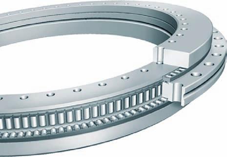
3 High precision bearings for combined loads Axial/radial bearings... 4 Axial/radial bearings are double direction axial bearings for screw mounting, with a radial guidance bearing. These ready-to-fit, pregreased units are very rigid, have high load carrying capacity and run with particularly high accuracy. They can support radial forces, axial forces from both directions and tilting moments free from clearance. The bearings are available in several series. For applications with low speeds and small operating durations, such as indexing tables and swivel type milling heads, the most suitable bearing is generally series YRT. Where comparatively lower friction and higher speeds are required, RTC bearings can be used. For higher requirements in accuracy, these bearings are also available with restricted axial runout accuracy. For the bearing arrangements of direct drive axes, there is the series YRT Speed. Due to their high limiting speeds and very low, uniform frictional torque across the whole speed range, these bearings are particularly suitable for combination with torque motors. Axial angular contact ball bearings... 4 Axial angular contact ball bearings ZKLDF are low-friction, ready-to-fit, pregreased bearing units with high accuracy for very high speeds, high axial and radial loads and high demands on tilting rigidity. Axial angular contact ball bearings are particularly suitable for precision applications involving combined loads. Their preferred areas of use are bearing arrangements in rotary tables, milling, grinding and honing heads as well as measurement and testing equipment. Axial/radial bearings with integral angular measuring system Axial/radial bearings with integral angular measuring system YRTM and YRTSM correspond in mechanical terms to the series YRT and YRTS but are additionally fitted with an angular measuring system. The measuring system can measure angles to an accuracy of a few angular seconds by noncontact, magneto-resistive means. 2 TPI 120 Schaeffler Group Industrial
4 YRT RTC YRT Speed ZKLDF YRTM/YRTSM SRM f Schaeffler Group Industrial TPI 120 3


5 3 d H M 1 C H H H 2 d D 1 Axial/radial bearings Axial angular contact ball bearings
6 Axial/radial bearings Axial angular contact ball bearings Page Product overview Axial/radial bearings, axial angular contact ball bearings... 6 Features Areas of application... 8 Axial/radial bearings... 9 Axial angular contact ball bearings... 9 Operating temperature... 9 Suffixes... 9 Design and safety guidelines Basic rating life Static load safety factor Static limiting load diagrams Limiting speeds Bearing preload Frictional torque Lubrication Design of adjacent construction Fits L-section ring without support ring/with support ring Fitting Accuracy Rigidity Static rigidity Special designs Dimension tables Axial/radial bearings, double direction, YRT Axial/radial bearings, double direction, RTC Axial/radial bearings, double direction, YRT Speed Axial angular contact ball bearings, double direction, ZKLDF Schaeffler Group Industrial TPI 120 5


7 Product overview Axial/radial bearings Axial angular contact ball bearings Axial/radial bearings YRT RTC b a For higher speeds YRT Speed c Axial angular contact ball bearings ZKLDF a 6 TPI 120 Schaeffler Group Industrial
8 Axial/radial bearings Axial angular contact ball bearings Features With angular measuring system Axial/radial bearings YRT, RTC and YRT Speed and axial angular contact ball bearings ZKLDF are ready-to-fit high precision bearings for high precision applications with combined loads. They can support radial loads, axial loads from both sides and tilting moments without clearance and are particularly suitable for bearing arrangements with high requirements for running accuracy, such as rotary tables, face plates, milling heads and reversible clamps. Due to the fixing holes in the bearing rings, the units are very easy to fit. The bearings are radially and axially preloaded after fitting. The mounting dimensions of all series are identical. Axial/radial bearings are also available with an angular measuring system. The measuring system can measure angles to an accuracy of a few angular seconds by non-contact, magneto-resistive means, see section Axial/radial bearings with integral angular measuring system, page 38. Schaeffler Group Industrial TPI 120 7


9 Axial/radial bearings Axial angular contact ball bearings Areas of application For standard applications with low speeds and small operating durations, such as indexing tables and swivel type milling heads, the most suitable bearing is generally series YRT, Figure 1. These bearings are available in two axial and radial runout accuracies. Where comparatively lower friction and higher speeds are required, RTC bearings can be used, Figure 1. For higher requirements in accuracy, these bearings are also available with restricted axial runout accuracy. For the bearing arrangements of direct drive axes, there is the series YRT Speed. Due to their high limiting speeds and very low, uniform frictional torque across the whole speed range, these bearings are particularly suitable for combination with torque motors, Figure 1. Axial angular contact ball bearings ZKLDF are particularly suitable for high speed applications with long operating duration, Figure 1. They are characterised by high tilting rigidity, low friction and low lubricant consumption ZKLDF YRT Speed RTC YRT n G = limiting speed c kl = tilting rigidity n G 4 Figure 1 Speed and tilting rigidity c kl 8 TPI 120 Schaeffler Group Industrial
10 Axial/radial bearings Sealing Lubrication Axial angular contact ball bearings Sealing Lubrication Operating temperature Suffixes Axial/radial bearings YRT, RTC and YRT Speed have an axial component and a radial component. The axial component comprises an axial needle roller or cylindrical roller and cage assembly, an outer ring, L-section ring and shaft locating washer and is axially preloaded after fitting. The radial component is a full complement (YRT, RTC) or cage-guided, preloaded cylindrical roller set. The outer ring, L-section ring and shaft locating washer have fixing holes. The unit is located by means of retaining screws for transport and safe handling. Axial/radial bearings are supplied without seals. Bearings of series YRT and YRT Speed are greased using a lithium complex soap grease to GA08 and can be lubricated via the outer ring and L-section ring. Arcanol LOAD150 is suitable for relubrication. Bearings of series RTC are greased with Arcanol MULTITOP. Axial angular contact ball bearings ZKLDF comprise a single-piece outer ring, a two-piece inner ring and two ball and cage assemblies with a contact angle of 60. The outer ring and inner ring have fixing holes for screw mounting of the bearing on the adjacent construction. The unit is located by means of retaining screws for transport and safe handling. Axial angular contact ball bearings have sealing shields on both sides. The bearings are greased with a barium complex soap grease to DIN KPE2K 30 and can be lubricated via the outer ring. Axial/radial bearings and axial angular contact ball bearings are suitable for operating temperatures from 30 C to +120 C. Suffixes for available designs: see table. Available designs Suffix Description Design H 1... Reduced tolerance on mounting dimension H 1 (postscript: H 1 with tolerance...) Restricted tolerance value, see table, page 25 H 2... Reduced tolerance on mounting dimension H 2 (postscript: H 2 with tolerance...) Restricted tolerance value, see table, page 25 Axial and radial runout tolerances restricted by 50% (additional text: axial/radial runout 50%) Special design, available by agreement Schaeffler Group Industrial TPI 120 9
11 Axial/radial bearings Axial angular contact ball bearings Design and safety guidelines Basic rating life Static load safety factor The load carrying capacity and life must be checked for the radial and axial bearing component. Please contact us in relation to checking of the basic rating life. The speed, load and operating duration must be given. The static load safety factor S 0 indicates the security against impermissible permanent deformations in the bearing: C S r or C a 0 = 0 0 F0r F0a S 0 Static load safety factor C 0r, C 0a N Basic static load rating according to dimension tables F 0r, F 0a N Equivalent static load on the radial or axial bearing. In machine tools and similar areas of application, S 0 should be 4. Static limiting load diagrams Axial/radial bearings Axial angular contact ball bearings The static limiting load diagrams can be used: for rapid checking of the selected bearing size under predominantly static load for calculation of the tilting moment M k that can be supported by the bearing in addition to the axial load. The limiting load diagrams are based on a rolling element set with a static load safety factor S 0 4, as well as the screw and bearing ring strength. The static limiting load must not be exceeded when dimensioning the bearing arrangement. Example: see Figure 2. The static limiting load diagrams for YRT, YRTS and RTC are shown in Figure 3, page 11 to Figure 9, page 13. The static limiting load diagrams for the series ZKLDF are shown in Figure 10 and Figure 11, page 13. Bearing, size Permissible range Impermissible range M k = maximum tilting moment F a = axial load M k Figure 2 Static limiting load diagram (example) F a TPI 120 Schaeffler Group Industrial
12 YRT 650 M k =maximum tilting moment F a =axial load Figure 3 Static limiting load diagram YRT50 to YRT Nm M k YRT 200 YRT 180 YRT 150 YRT 120 YRT 100 YRT 50 YRT 80-TV F a Nm N a YRT YRT 395 M k =maximum tilting moment F a =axial load Figure 4 Static limiting load diagram YRT260 to YRT460 M k YRT 325 YRT N F a a Nm YRT M k YRT 580 M k =maximum tilting moment F a =axial load Figure 5 Static limiting load diagram YRT580 to YRT F a N a Schaeffler Group Industrial TPI
13 Axial/radial bearings Axial angular contact ball bearings Nm YRT 950 YRT 1030 M k = maximum tilting moment F a = axial load Figure 6 Static limiting load diagram YRT950 and YRT1030 M k F a N a Nm YRTS YRTS 395 YRTS 325 M k YRTS 260 M k = maximum tilting moment F a = axial load Figure 7 Static limiting load diagram YRT Speed 200 to YRT Speed YRTS N F a a Nm RTC180 RTC RTC120 M k = maximum tilting moment F a = axial load Figure 8 Static limiting load diagram RTC80 to RTC180 M k RTC100 RTC N F a TPI 120 Schaeffler Group Industrial
14 80000 Nm RTC M k RTC395 RTC325 M k =maximum tilting moment F a =axial load Figure 9 Static limiting load diagram RTC200 to RTC RTC200 RTC N F a 6000 Nm 5000 ZKLDF ZKLDF 150 M k 2000 ZKLDF 120 M k =maximum tilting moment F a =axial load Figure 10 Static limiting load diagram ZKLDF100 to ZKLDF Nm ZKLDF 100 ZKLDF 460 ZKLDF N F a a M k =maximum tilting moment F a =axial load Figure 11 Static limiting load diagram ZKLDF260 to ZKLDF M k ZKLDF 325 ZKLDF F a N a Schaeffler Group Industrial TPI
15 Axial/radial bearings Axial angular contact ball bearings Limiting speeds Bearing preload Temperature differences The bearings allow the limiting speeds n G given in the dimension tables. The operating temperatures occurring are heavily dependent on the environmental conditions. Calculation is possible by means of a thermal balance analysis based on frictional torque data. If the environmental conditions differ from the specifications in relation to adjacent construction tolerances, lubrication, ambient temperature, heat dissipation or from the normal operating conditions for machine tools, checking must be carried out again. Please contact us. Once the bearings have been fitted and fully screw mounted, they are radially and axially clearance-free and preloaded. Temperature differences between the shaft and housing influence the radial bearing preload and thus the operating behaviour of the bearing arrangement. If the shaft temperature is higher than the housing temperature, the radial preload will increase proportionally, so there will be an increase in the rolling element load, bearing friction and bearing temperature. If the shaft temperature is lower than the housing temperature, the radial preload will decrease proportionally, so the rigidity will decrease to the point of bearing clearance and wear will increase. 14 TPI 120 Schaeffler Group Industrial
16 Frictional torque M RL = frictional torque n = speed Figure 12 Frictional torques as guide values for YRT Speed, statistically determined values from series of measurements Frictional energy and dimensioning of the drive The bearing frictional torque M RL is influenced primarily by the viscosity and quantity of the lubricant and the bearing preload: The lubricant viscosity and quantity are dependent on the lubricant grade and operating temperature. The bearing preload is dependent on the mounting fits, the geometrical accuracy of the adjacent parts, the temperature difference between the inner and outer ring, the screw tightening torque and the mounting situation (bearing inner ring axially supported on one or both sides). The frictional torques M RL in the dimension tables are statistically determined guide values for bearings with grease lubrication (measurement speed n const =5min 1 ). Figure 12 shows measured frictional torques for mounting with an unsupported L-section ring for YRT Speed. Deviations from the tightening torque of the fixing screws will have a detrimental effect on the preload and the frictional torque. 22,5 Nm 20 17, ,5 10 MRL 7,5 5 YRT 460 Speed YRT 395 Speed YRT 325 Speed YRT 260 Speed YRT 200 Speed 2, n min 1 For YRT and RTC bearings, it must be taken into consideration that the frictional torque can increase by a factor of 2 to 2,5 with increasing speed. For ZKLDF bearings, it must be taken into consideration that the starting frictional torque can be 1,5 times higher than the values M RL in the dimension tables e4b Schaeffler Group Industrial TPI
17 Axial/radial bearings Axial angular contact ball bearings Lubrication Overlubrication Axial/radial bearings YRT, RTC and YRT Speed can be relubricated via the L-section ring and outer ring. Axial angular contact ball bearings ZKLDF can be relubricated via the outer ring. The initial greasing is compatible with lubricating oils having a mineral oil base. For calculation of the relubrication quantities and intervals based on a stated load spectrum (speed, load, operating duration) and the environmental conditions, please contact us. If the bearing is overlubricated, the bearing frictional torque and the temperature will increase. In order to achieve the original frictional torque again, the running-in cycle in accordance with Figure 13 should be carried out. Note the further information on lubrication in Catalogue HR1, chapter Lubrication. % n G 20 n G = limiting speed according to dimension tables t=time 10 Figure 13 Running-in cycle after overlubrication 0 1 t 2 3 h a54 Grease Application Group GA08 Designation Classification Type of grease Operating temperature NLGI class Speed parameter n d M ISO VG class (base oil) 1) C min 1 mm GA08 Grease for line contact Lithium complex soap Mineral oil 30 to to to 320 1) Dependent on bearing type. 16 TPI 120 Schaeffler Group Industrial
18 Design of adjacent construction YRT, RTC, YRT Speed and ZKLDF have almost the same mounting dimensions. Geometrical defects in the screw mounting surfaces and fits will influence the running accuracy, preload and running characteristics of the bearing arrangement. The accuracy of the adjacent surfaces must therefore be matched to the overall accuracy requirement of the subassembly. The tolerances of the adjacent surfaces must lie within the running tolerance of the bearing. The adjacent construction should be produced in accordance with Figure 14 and the tolerances must be in accordance with the tables starting on page 20. Any deviations will influence the bearing frictional torque, running accuracy and running characteristics. R max 4) c H 0,8 t 8 C A C d 1) h5 t 2 // t6 A 0,8 B DJ6 2) 0,8 t 2 t 8 B 0,8 Figure 14 Requirements for the adjacent construction, YRT, RTC, YRT Speed, ZKLDF R max 4) D A 3) Legend to Figure 14 1) Support over whole bearing height. It must be ensured that the means of support has adequate rigidity. 2) A precise fit is only necessary if radial support due to the load or a precise bearing position is required. 3) Note the bearing diameter D 1 according to the dimension tables. Ensure that there is sufficient distance between the rotating bearing rings and the adjacent construction. 4) For values, see table Maximum corner radii of fit surfaces, page 21. Schaeffler Group Industrial TPI
19 Axial/radial bearings Axial angular contact ball bearings Fits Axial and radial runout accuracy of the bearing arrangement Recommended fits for shafts The selection of fits leads to transition fits which means that, depending on the actual dimensional position of the bearing diameter and mounting dimensions, clearance fits or interference fits can arise. The fit influences, for example, the running accuracy of the bearing and its dynamic characteristics. An excessively tight fit will increase the radial bearing preload. As a result: there is an increase in bearing friction and heat generation in the bearing as well as the load on the raceway system and wear there will be a decrease in the achievable speed and the bearing operating life. For easier matching of the adjacent construction to the actual bearing dimensions, each bearing of series RTC and YRT Speed is supplied with a measurement record (this is supplied by agreement for other series). The axial and radial runout accuracy is influenced by: the running accuracy of the bearing the geometrical accuracy of the adjacent surfaces the fit between the rotating bearing ring and adjacent component. In order to achieve very high running accuracy, the aim should be to achieve as close as possible to a fit clearance 0. The shaft should be produced to tolerance zone h5 and for series YRT Speed in accordance with the table, page 21. If there are special requirements, the fit clearance must be further restricted within the tolerance zone h5: Requirements for running accuracy: For maximum running accuracy and with a rotating bearing inner ring, the aim should be to achieve as close as possible to a fit clearance of 0. The fit clearance may otherwise increase the bearing runout. With normal requirements for running accuracy or a stationary bearing inner ring, the shaft should be produced to h5. Requirements for dynamic characteristics: For swivel type operation (n d min 1 mm, operating duration ED 10%) the shaft should be produced to h5 For higher speeds and longer operating duration 0,01 mm the fit clearance must not be exceeded. For series YRT Speed 0,005 mm must not be exceeded as a fit clearance. For series ZKLDF, the fit clearance should be based on the inner ring with the smallest bore dimension. 18 TPI 120 Schaeffler Group Industrial
20 Recommended fits for housings Fit selection depending on the screw connection of the bearing rings The housing should be produced to tolerance zone J6 and for series YRT Speed according to the table Recommended fits, page 21. If there are special requirements, the fit clearance must be further restricted within the tolerance zone J6: Requirements for running accuracy: For maximum running accuracy and with a rotating bearing outer ring, the aim should be to achieve as close as possible to a fit clearance of 0. With a static bearing outer ring, a clearance fit or a design without radial centring should be selected. Requirements for dynamic characteristics: For predominantly swivel type operation (n d min 1 mm, operating duration ED 10%) and a rotating bearing outer ring, the housing fit should be produced to tolerance zone J6 For higher speed and operating duration, the bearing outer ring should not be radially centred or the housing fit should be produced as a clearance fit with at least 0,02 mm clearance. This reduces the increase in preload when heat is generated in the bearing position. If the bearing outer ring is screw mounted on the static component, a fit seating is not required or a fit seating in accordance with the table Recommended fits for adjacent construction, page 21, can be produced. If the values in the table are used, this will give a transition fit with a tendency towards clearance fit. This generally allows easy fitting. If the bearing inner ring is screw mounted on the static component, it should nevertheless for functional reasons be supported by the shaft over the whole bearing height. The shaft dimensions should then be selected in accordance with the tables starting on page 20. If these values in the table are used, this will give a transition fit with a tendency towards clearance fit. Schaeffler Group Industrial TPI
21 Axial/radial bearings Axial angular contact ball bearings Geometrical and positional accuracy of the adjacent construction Geometrical and positional accuracy for shafts with YRT, RTC, ZKLDF Geometrical and positional accuracy for housings with YRT, RTC, ZKLDF The values given in the following tables for geometrical and positional accuracy of the adjacent construction have proved effective in practice and are adequate for the majority of applications. The geometrical tolerances influence the axial and radial runout accuracy of the subassembly as well as the bearing frictional torque and the running characteristics. Nominal shaft diameter Deviation Roundness Parallelism Perpendicularity d mm d t 2, t 6, t 8 for tolerance zone h5 over incl. m m Nominal housing bore diameter Deviation Roundness Perpendicularity D mm D t 2, t 8 for tolerance zone J6 over incl. m m TPI 120 Schaeffler Group Industrial
22 Recommended fits for shaft and housing bore with YRT Speed Axial/radial bearing Shaft diameter d mm Housing bore D mm YRT Speed , 200 0, , , 005 YRT Speed 260 0, , , , 005 YRT Speed 325 0, , , , 005 YRT Speed 395 0, , , , 005 YRT Speed 460 0, , , , 005 Geometrical and positional accuracy for shafts with YRT Speed Geometrical and positional accuracy for housings with YRT Speed Maximum corner radii of fit surfaces with YRT, RTC, YRT Speed, ZKLDF Axial/radial bearing Roundness Parallelism Perpendicularity t 2 t 6 t 8 m m m YRT Speed YRT Speed 260 to YRT Speed Axial/radial bearing Roundness Perpendicularity t 2 t 8 m m YRT Speed 200 to YRT Speed Bore diameter d mm Maximum corner radius R max mm 50 incl ,1 over 150 incl ,3 over 460 incl Schaeffler Group Industrial TPI
23 Axial/radial bearings Axial angular contact ball bearings Mounting dimensions H 1, H 2 If the height variation must be as small as possible, the H 1 dimensional tolerance must conform to the tables on page 25, page 26 and Figure 15. The mounting dimension H 2 defines the position of any worm wheel used, Figure 15 and Figure 16, page 23, L-section ring with support ring. H 1 H 2 Figure 15 Mounting dimension H 1, H 2 L-section ring without support ring or with support ring L-section ring without support ring The L-section ring of bearings YRT and RTC can be mounted unsupported or supported over its whole surface, Figure 16. If the L-section ring is supported, the tilting rigidity is higher. The support ring (for example a worm wheel) is not included in the delivery. Depending on the application, series YRT and RTC require bearings with a different preload match in order to achieve the same preload forces in the axial bearing. For series YRT Speed and ZKLDF, there is only one preload match. The increase in rigidity and frictional torque in YRT Speed bearings is slight and can normally be ignored. In bearings of series ZKLDF, the rigidity and frictional torque are not influenced by the support ring. For the case L-section ring without support ring, the bearing designation is: YRT bore diameter or RTC bore diameter a 22 TPI 120 Schaeffler Group Industrial
24 L-section ring with support ring YRT RTC For the case "L-section ring with support ring", the bearing designation is: YRT bore diameter VSP RTC bore diameter T52EB. For RTC with an additionally restricted axial runout, the bearing designation is: RTC bore diameter T52EA. For bearing arrangements with a supported L-section ring, only bearings with the suffix VSP, EB or T52EA can be ordered. If the normal design is mounted with a supported L-section ring, there will be a considerable increase in the bearing frictional torque. The support ring should be at least twice as high as the shaft locating washer of the bearing. 1 H 1 YRT..VSP RTC..T52EB RTC..T52EA 2 H 1 Figure 16 L-section ring without support ring, L-section ring with support ring for YRT, RTC H b Schaeffler Group Industrial TPI

25 Axial/radial bearings Axial angular contact ball bearings Fitting Retaining screws secure the bearing components during transport. For easier centring of the bearing, the screws should be loosened before fitting and either secured again or removed after fitting. Tighten the fixing screws in crosswise sequence using a torque wrench in three stages to the specified tightening torque M A, while rotating the bearing ZKLDF, Figure 17: Stage 1: 40% of M A Stage 2: 70% of M A Stage 3: 100% of M A. Observe the correct grade of the fixing screws. Mounting forces must only be applied to the bearing ring to be fitted, never through the rolling elements. Bearing components must not be separated or interchanged during fitting and dismantling. If the bearing is unusually difficult to move, loosen the fixing screws and tighten them again in steps in a crosswise sequence. This will eliminate any distortion. Bearings should only be fitted in accordance with TPI 103, Fitting and Maintenance Manual Figure 17 Tightening of fixing screws b 24 TPI 120 Schaeffler Group Industrial
26 Accuracy The dimensional tolerances are derived from tolerance class P5. The diameter tolerances stated are mean values in accordance with ISO The geometrical tolerances correspond to P4 in DIN 620, see table. The bearing bore in the series YRT, RTC and YRT Speed may be slightly conical when delivered. This is typical of the bearing design and is a result of the radial bearing preload forces. The bearing will regain its ideal geometry when fitted. Dimensional tolerances, mounting dimensions, axial and radial runout for YRT, ZKLDF Restricted 3) Restricted 3) Dimensional tolerances 1) Mounting dimensions Axial and radial runout 2) Bore Outside diameter Normal Restricted 3) d ds D Ds H 1 H1s H1s H 2 H2s mm mm mm mm mm mm mm mm mm m m 50 0, , ,125 0, , , ,011 23,35 0,15 0,025 11,65 0,02 3 1, , , ,175 0, ,02 3 1, , , ,175 0, ,02 3 1, , , ,175 0, ,02 3 1, , , ,175 0, , , , ,175 0, , , ,02 36,5 0,2 0,04 18,5 0, , , ,2 0, , , ,028 42,5 0,2 0,05 22,5 0, , , ,225 0, , , , ,25 0, , ) 650 0, , ,25 0,1 44 0, ) 850 0, ,063 80,5 0,3 0,12 43,5 0, ) 950 0, , ,3 0, , ) , ,08 92,5 0,3 0,15 52,5 0, ) 1) The diameter tolerances stated are mean values (DIN 620). 2) For rotating inner and outer ring, measured on fitted bearing, with ideal adjacent construction. 3) Special design, YRT only. 4) By agreement only for rotating outer ring. Schaeffler Group Industrial TPI
27 Axial/radial bearings Axial angular contact ball bearings Dimensional tolerances, mounting dimensions, axial and radial runout for RTC Dimensional tolerances Bore Outside diameter Bearing height Mounting dimensions Axial and radial runout 1) Normal Axial runout 1) Restricted d ds D Ds H Hs H 1 H1s mm mm mm mm mm mm mm mm m m 80 0, , ,025 0,15 23,35 0, , , , ,025 0, , , , , ,025 0, , , , , ,03 0, ,03 3 1, , , ,03 0, , , , ,03 0,2 30 0, , , ,04 0,25 36,5 0, , , ,05 0,3 40 0, , , ,05 0,3 42,5 0, , , ,06 0, , ) For rotating inner and outer ring, measured on fitted bearing, with ideal adjacent construction. Dimensional tolerances, mounting dimensions, axial and radial runout for YRT Speed Dimensional tolerances Mounting dimensions Axial and radial runout 1) Bore Outside diameter Normal Restricted 2) d ds D Ds H 1 H1s H 2 mm mm mm mm mm mm mm m m 200 0, , ,04 0, , ,02 36,5 +0,05 0,07 18, , , ,06 0, , ,028 42,5 +0,06 0,07 22, , , ,07 0, ) For rotating inner and outer ring, measured on fitted bearing, with ideal adjacent construction. 2) Restricted axial and radial runout only available for rotating inner ring. 26 TPI 120 Schaeffler Group Industrial
28 Rigidity Static rigidity Special designs The overall rigidity of a bearing position is a description of the magnitude of the displacement of the rotational axis from its ideal position under load. The static rigidity thus has a direct influence on the accuracy of the machining results. The dimension tables give the rigidity values for the complete bearing position, see page 28 to page 37. These take account of the deflection of the rolling element set as well as the deformation of the bearing rings and the screw connections. The values for the rolling element sets are calculated rigidity values and are for information purposes only. They facilitate comparison with other bearing types, since rolling bearing catalogues generally only give the higher rigidity values for the rolling element set. Available by agreement: For YRT, axial and radial runout tolerance restricted by 50%. Additional text: axial and radial runout 50%. For RTC, axial runout tolerance restricted by 50%. Additional text: axial runout 50%. For YRT, closer tolerance on mounting dimension H 1 and H 2. Additional text: H 1 with tolerance..., H 2 with tolerance... For restricted tolerance value, see table, page 25. Schaeffler Group Industrial TPI
29 Axial/radial bearings Double direction D J1 J d1 d a C H 1 H d2 a d D1 H 2 YRT Dimension table Dimensions in mm Designation Mass Dimensions Fixing holes m d D H H 1 H 2 C D 1 J J 1 Inner ring Outer ring d 1 d 2 a Quantity 4) tity d 3 Quan- 4) kg max. YRT50 1, ,6 10 5,6 12 YRT80-TV 5)7) 2, ,35 11, , ,6 12 YRT100 5) 4, ,6 10 5,4 16 5,6 15 YRT120 5, , YRT150 6, , YRT180 7, , YRT200 9, , YRT260 18, ,5 18, ,3 15 8,2 34 9,3 33 1) Including retaining screws or threaded extraction holes. 2) Tightening torque for screws to DIN 912, grade ) Rigidity values taking account of the rolling element set, the deformation of the bearing rings and the screw connections. For explanations, see page 27. 4) Attention! For fixing holes in the adjacent construction. Observe the pitch of the bearing holes. 5) Screw counterbores in the L-section ring open to the bearing bore. The bearing inside diameter is unsupported in the area. 6) For high operating durations or continuous operation, please contact us. 7) Cages made from glass fibre reinforced polyamide TPI 120 Schaeffler Group Industrial
30 G a a t 2 1 Hole pattern Two retaining screws For YRT80-TV and YRT100: Screw counterbores open 5) Pitch t 1) Threaded extraction hole Screw tightening torque Basic load ratings QuantityXt G Quantity axial radial M 2) A dyn. C a stat. C 0a dyn. C r Limiting speed 6) stat. n G M RL C 0r Bearing frictional torque Nm N N N N min 1 Nm 12X30 8, ,5 12X30 8,5/4, X20 M5 3 8, X15 M X10 M X 7,5 M X 7,5 M X10 M Designation Rigidity of bearing position 3) axial radial Tilting rigidity of rolling element set axial radial Tilting rigidity c al c rl c kl c al c rl c kl kn/ m kn/ m knm/mrad kn/ m kn/ m knm/mrad YRT50 1,3 1,1 1,25 6,2 1,5 5,9 YRT80-TV 5)7) 1,6 1,8 2,5 4 2,6 6,3 YRT100 5) ,8 2,4 15 YRT120 2,1 2,2 7 7,8 3,8 24 YRT150 2,3 2,6 11 8,7 4,6 38 YRT180 2, ,9 5,3 57 YRT , ,2 6,2 80 YRT260 3,5 4, ,7 8,1 155 Schaeffler Group Industrial TPI
31 Axial/radial bearings Double direction D J1 J d1 d a C H 1 H d2 a d D1 H 2 YRT Dimension table (continued) Dimensions in mm Designation Mass Dimensions Fixing holes m d D H H 1 H 2 C D 1 J J 1 Inner ring Outer ring d 1 d 2 a Quantity 4) tity d 3 Quan- 4) kg max. YRT325 5) ,3 15 8,2 34 9,3 33 YRT ,5 22, ,3 15 8,2 46 9,3 45 YRT ,3 15 8,2 46 9,3 45 YRT , ,4 42 YRT YRT ,5 43, YRT950 7) YRT , ) Including retaining screws or threaded extraction holes. 2) Tightening torque for screws to DIN 912, grade ) Rigidity values taking account of the rolling element set, the deformation of the bearing rings and the screw connections. For explanations, see page 27. 4) Attention! For fixing holes in the adjacent construction. Observe the pitch of the bearing holes. 5) Screw counterbores in the L-section ring open to the bearing bore. The bearing inside diameter is unsupported in the area. 6) For high operating durations or continuous operation, please contact us. 7) Available by agreement only. 30 TPI 120 Schaeffler Group Industrial
32 G a a t 2 1 Hole pattern Two retaining screws For YRT325: Screw counterbores open 5) Pitch t 1) Threaded extraction hole Screw tightening torque Basic load ratings QuantityXt G Quantity axial radial M 2) A dyn. C a stat. C 0a dyn. C r Limiting speed 6) stat. n G M RL C 0r Bearing frictional torque Nm N N N N min 1 Nm 36X10 M X 7,5 M X 7,5 M X 7,5 M X 7,5 M X 6 M X 6 M X 5 M Designation Rigidity of bearing position 3) axial radial Tilting rigidity of rolling element set axial radial Tilting rigidity c al c rl c kl c al c rl c kl kn/ m kn/ m knm/mrad kn/ m kn/ m knm/mrad YRT325 5) 4, ,1 9,4 422 YRT395 4, ,3 11,3 684 YRT460 5, ,5 13, YRT580 6, ,1 17, YRT650 7, ,3 13, YRT850 9, ,4 20, YRT950 7) 10, ,5 16, YRT , ,7 18, Schaeffler Group Industrial TPI
33 Axial/radial bearings Double direction D J1 J d1 d e C H 1 H d2 a d D1 RTC Dimension table Dimensions in mm Designation Mass Dimensions 7) Fixing holes m d D H H 1 C D 1 J J 1 Inner ring Outer ring d 1 d 2 a Quantity 4) tity d 3 Quan- 4) kg max. RTC80 5) , ,6 10 5,7 12 4,6 12 RTC100 5) ,6 10 5,7 15 5,6 18 RTC RTC150 5, RTC RTC200 9, RTC , ,3 15 9,3 33 9,3 36 RTC325 5) ,3 15 9,3 33 9,3 36 RTC , ,3 15 9,3 45 9,3 48 RTC ,3 15 9,3 45 9,3 48 1) Including retaining screws or threaded extraction holes. 2) Tightening torque for screws to DIN 912, grade ) Rigidity values taking account of the rolling element set, the deformation of the bearing rings and the screw connections. For explanations, see page 27. 4) Attention! For fixing holes in the adjacent construction. Observe the pitch of the bearing holes. 5) Screw counterbores in the L-section ring open to the bearing bore. The bearing inside diameter is unsupported in the area. 6) For high operating durations or continuous operation, please contact us. 7) Sizes d 460 mm available by agreement. 32 TPI 120 Schaeffler Group Industrial
34 G b 00014a56 t t/2 1 2 Hole pattern Three retaining screws For RTC80, RTC100 and RTC325: Screw counterbores open 5) Pitch t 1) Threaded extraction hole Screw tightening torque Basic load ratings QuantityXt G Quantity axial radial M 2) A dyn. C a stat. C 0a dyn. C r Limiting speed 6) stat. n G M RL C 0r Bearing frictional torque Nm N N N N min 1 Nm 12X30 8, X20 M5 3 8, X15 M X10 M X 7,5 M X 7,5 M X10 M X10 M X 7,5 M X 7,5 M Designation Rigidity of bearing position 3) axial radial Tilting rigidity of rolling element set axial radial Tilting rigidity c al c rl c kl c al c rl c kl kn/ m kn/ m knm/mrad kn/ m kn/ m knm/mrad RTC80 5) 0,71 1,8 1,6 5,6 2,1 9 RTC100 5) 1, ,1 3,5 21 RTC120 1,3 2,2 7 9,1 5,7 29 RTC150 1,5 2, ,6 7,1 45 RTC180 1, ,6 6,3 67 RTC200 1,8 3, ,2 5,8 88 RTC260 2,1 4, ,4 7,5 201 RTC325 5) 2, ,5 429 RTC395 3, ,9 11,9 698 RTC460 3, ,6 13, Schaeffler Group Industrial TPI
35 Axial/radial bearings Double direction d1 D J 1 J d d C H 1 H d2 a d D1 H 2 YRT Speed Dimension table Dimensions in mm Designation Mass Dimensions Fixing holes m d D H H 1 H 2 C D 1 J J 1 Inner ring Outer ring d 1 d 2 a Quantity 3) tity d 3 Quan- 3) kg YRTS200 9, , YRTS260 18, ,5 18, ,3 15 8,2 34 9,3 33 YRTS325 5) ,3 15 8,2 5) 34 9,3 33 YRTS ,5 22, ,3 15 8,2 46 9,3 45 YRTS ,3 15 8,2 46 9,3 45 1) Including retaining screws or threaded extraction holes. 2) For screws to DIN 912, grade ) Attention! For fixing holes in the adjacent construction. Observe the pitch of the bearing holes. 4) Rigidity values taking account of the rolling element set, the deformation of the bearing rings and the screw connections. For explanations, see page 27. 5) Screw counterbores in the L-section ring open to the bearing bore. The bearing inside diameter is unsupported in the area. 34 TPI 120 Schaeffler Group Industrial
36 G a t 2 1 Hole pattern Two retaining screws For YRTS325: Screw counterbores open 5) Pitch t 1) Threaded extraction hole Screw tightening torque Basic load ratings Limiting speed Mass moment of inertia for rotating QuantityXt G Quantity axial radial inner ring IR M A 2) dyn. C a stat. C 0a dyn. C r stat. n G M M C 0r outer ring AU Nm N N N N min 1 kg cm 2 kg cm 2 48X 7,5 M X10 M X10 M X 7,5 M X 7,5 M Designation Rigidity of bearing position 4) axial radial Tilting rigidity of rolling element set axial radial Tilting rigidity c al c rl c kl c al c rl c kl kn/ m kn/ m knm/mrad kn/ m kn/ m knm/mrad YRTS , ,6 3,9 101 YRTS260 5,4 1, ,8 5,8 201 YRTS325 5) 6,6 1, ,9 7,1 350 YRTS395 7, ,4 8,7 582 YRTS460 8,9 1, ,4 9,5 843 Schaeffler Group Industrial TPI
37 Axial angular contact ball bearings Double direction d2 d 1 a D J 1 D3 D2 J d D 1 60 d 3 1 a H1 H a ZKLDF Contact surface/centring diameter Dimension table Dimensions in mm Designation Mass Dimensions 6) Inner ring m d D H H 1 D 1 D 2 D 3 J J 1 a Fixing screws d 1 d 2 Quantity 4) kg ZKLDF100 5) 4, ,4 5, ZKLDF , ZKLDF150 7, , ZKLDF , ZKLDF , ,2 9, ZKLDF325 5) ,2 9, ZKLDF , ,2 9, ZKLDF ,2 9, ) Including retaining screws or threaded extraction holes. 2) Tightening torque for screws to DIN 912, grade ) Rigidity values taking account of the rolling element set, deformation of the bearing rings and the screw connections. For explanations, see page 27. 4) Attention! For fixing holes in the adjacent construction. Observe the pitch of the bearing holes. 5) Screw counterbores in the L-section ring open to the bearing bore. The bearing inside diameter is unsupported in the area. 6) Sizes d 460 mm available by agreement. 7) Valid for matched adjacent construction. 36 TPI 120 Schaeffler Group Industrial
38 G c 00014a7a t 3 2 Hole pattern Two retaining screws For ZKLDF100, ZKLDF325: Screw counterbores open 5) Outer ring Fixing screws Threaded extraction hole d 3 Quantity 4) G Quantity Pitch t 1) Screw tightening torque Basic load ratings axial QuantityXt M 2) A dyn. C a Limiting speed 7) stat. n G M RL C 0a Bearing frictional torque Nm N N min 1 Nm 5,6 15 M5 3 18X20 8, , M8 3 24X M8 3 36X M8 3 48X 7, ,5 9,3 33 M X ,5 9,3 33 M X ,3 45 M X 7, ,3 45 M X 7, Designation Rigidity of bearing position 3) axial radial Tilting rigidity of rolling element set axial radial Tilting rigidity c al c rl c kl c al c rl c kl kn/ m kn/ m knm/mrad kn/ m kn/ m knm/mrad ZKLDF100 5) 1,2 0,35 3,6 2,2 0,35 5 ZKLDF120 1,5 0,4 5,5 2,5 0,4 8 ZKLDF150 1,7 0,4 7,8 2,9 0,4 12 ZKLDF200 2,5 0,6 17,5 3,7 0,6 26 ZKLDF260 3,2 0,7 40 4,7 0,7 54 ZKLDF325 5) 4 0,8 60 5,4 0,8 90 ZKLDF395 4,5 0, ,3 0,9 148 ZKLDF460 6) 5,3 1, ,1 1,1 223 Schaeffler Group Industrial TPI


39 1 J d D J 1 d a d 2 D 1 Axial/radial bearings with integral angular measuring system
40 Axial/radial bearings with integral angular measuring system Page Product overview Intergral angular measuring system Features Advantages of the angular measuring system Dimensional scale Measuring heads with magneto-resistive sensors Electronic evaluation system Cables for signal transmission Setting and diagnosis program Measurement accuracy Error-free signal transmission Measures to protect against interference Laying of signal cables Compatibility Test according to standard Technical data Detection of zero position, functional principle Special design Design and safety guidelines Ordering example, ordering designation Dimension tables Design of adjacent construction Fitting Unit Also required Replacement parts Axial/radial bearings, double direction, with measuring system SRM electronic measuring system Schaeffler Group Industrial TPI


41 Product overview Axial/radial bearings with integral angular measuring system Axial/radial bearings With magnetic dimensional scale YRTM, YRTSM c Electronic measuring system Measuring heads with shims SRM Electronic evaluation system a Connection cable For measuring heads and electronic measuring system SRMC TPI 120 Schaeffler Group Industrial
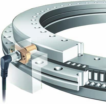
42 Axial/radial bearings with integral angular measuring system Features Axial/radial bearings with integral angular measuring system comprise: an axial/radial bearing YRTM or YRTSM with a dimensional scale, an SRM electronic measuring system and signal leads SRMC. The electronic measuring system SRM comprises two measuring heads, two stacks of shims and an electronic evaluation system. The signal leads for connecting the measuring heads to the electronic evaluation system can be ordered individually in various designs. The electronic measuring system MEKO/U will continue to be available but should no longer be used for new designs. Bearings of series YRTM or YRTSM correspond in mechanical terms to axial/radial bearings YRT or YRTS but are additionally fitted with a magnetic dimensional scale. The measuring system can measure angles to an accuracy of a few angular seconds by noncontact, magneto-resistive means. For the mechanical part of axial/radial bearings YRTM or YRTSM, please refer to the information from page 7 to page 27. Schaeffler Group Industrial TPI
43 Axial/radial bearings with integral angular measuring system Advantages of the angular measuring system The measuring system, Figure 1: allows, due to the rigid connection to the adjacent construction, very good control characteristics (control stability and dynamics) and is therefore particularly suitable for axes with torque motor drive offers a high maximum speed of up to 16,5 m/s operates by non-contact means and is therefore not subject to wear carries out measurement irrespective of tilting and position has automatically self-adjusting electronics has a self-centring function is unaffected by lubricants is easy to fit, the measuring heads are easily adjustable, there is no need for alignment of the bearing and a separate measuring system requires no additional parts the dimensional scale and measuring heads are integrated in the bearing and adjacent construction respectively the resulting space saved can be used for the machining area of the machine does not give any problems relating to supply cables. The cables can be laid within the adjacent construction directly through the large bearing bore gives savings on design envelope size and costs due to the compact, integrated design requiring fewer components. 1 2 Magnetic scale Magnetic field lines Measuring head with magneto-resistive sensor Electronic evaluation system Analogue signals at output ,5V +0,5V Figure 1 Measurement principle TPI 120 Schaeffler Group Industrial
44 Axial/radial bearings with integral angular measuring system Dimensional scale The dimensional scale is applied without seams or joins to the outside diameter of the shaft locating washer. Magnetic poles are present as angle references, Figure 2 on the magnetisable, electroplated coating at a pitch of 250 m. The angular position is measured incrementally, i.e. by counting the individual increments. For a fixed datum point for the angular position after the machine is switched on, an additional reference mark is therefore also required. X 250 m X Figure 2 Dimensional scale Reference marks The system has pitch-coded reference marks in order to quickly create the absolute datum point. Every 15, reference marks are applied with defined different pitches, so that the absolute datum point is achieved by passing over two adjacent reference marks (maximum 30 ) c Schaeffler Group Industrial TPI
45 Axial/radial bearings with integral angular measuring system Measuring heads with magneto-resistive sensors MR effect O rings for sealing Electronic evaluation system The measuring heads are colour coded: the silver measuring head (white) scans the incremental track the gold measuring head (yellow) scans the incremental track and the reference marks. The two measuring heads are designed for optimum use of space. They are fixed in a slot in the adjacent construction by means of two fixing screws. The small magnetic fields are detected as a result of the magneto-resistive effect (MR effect). Compared with magnetic heads, the MR sensors allow static measurement of magnetic fields, i.e. electrical signals are derived without movement, in contrast to magnetic heads. The resistance layer of the MR sensors is designed such that the resistance changes when a magnetic field is perpendicular to the current flow. When the magnetic pitch moves past the MR sensor, two sine wave signals with a phase offset of 90 are generated with a period length of 500 m. The measuring heads have O rings to seal against the egress of oil and the ingress of fluids such as cooling lubricants. The electronic evaluation system operates with the aid of a digital signal processor (DSP). The input signals are digitised by an analogue/digital converter. The high performance processor (DSP) automatically compares the sensor signals and calculates the effective angular value from the sensor signals by means of vector addition. Correction is carried out, for example, on the offset of the analogue signals. A digital/analogue converter generates synthetic analogue signals as a 1 V SS value. The electronic evaluation system can be positioned at any location or within the adjacent construction. It is connected to the controller by means of a conventional 12-pin extension cable. The lead for transmitting the voltage signals from the electronic evaluation system to the electronic post-processor can be up to 100 m long. 44 TPI 120 Schaeffler Group Industrial
46 Cables for signal transmission Advantages Bending cycles Plug connectors The signal cables for connecting the measuring heads to the electronic evaluation system are available in the lengths 1 m, 2 m and 3 m, see table, page 46. The connection side for the electronic evaluation system has a straight plug. The connection side to the measuring head is suitable for straight plugs or 90 elbow plugs. In the case of the elbow plug, the cable outlet direction is defined in relation to the mounting position of the measuring heads. The cables are suitable for use in machinery and plant for chip-forming machining: the cables and plugs are shielded the cable sheathing is made from polyurethane (PUR), halogen-free and flame-resistant the signal cables are free from halogens, silicones and PVC as well as resistant to microbes and hydrolysis the cables are resistant to oils, greases and cooling lubricants, see TPI 154, Integral angular measuring system the cables are suitable for dynamic use in flexible trunking (it must be ensured that they are laid correctly). When laid in flexible trunking, the cables can achieve 2million bending cycles under the following test conditions: bending radius 65 mm (10 D) acceleration 5 m/s 2 travel speed 200 m/min travel distance 5 m, horizontally. INA plug connectors are robust and designed for use in industrial environments. When connected, they conform to protection grade IP 65 (EN ). The large sheathed areas of the plugs ensure effective shielding. Schaeffler Group Industrial TPI
 Straight plug (SRMC..-S) 1 Figure 3 Connection cable Designs Design and length of connection cable, see table. Other designs available by agreement.")
47 Axial/radial bearings with integral angular measuring system Connection cables Measuring heads are connected using cables with 90 elbow plugs or cables with straight plugs, Figure elbow plug (SRMC..-A) Straight plug (SRMC..-S) 1 Figure 3 Connection cable Designs Design and length of connection cable, see table. Other designs available by agreement. 2 Plug design Cable length Ordering m designation Straight plugs on both ends 1 SRMC1-S 2 SRMC2-S 3 SRMC3-S Straight plug 1 SRMC1-A and 90 elbow plug 2 SRMC2-A 3 SRMC3-A Dimensions of plugs and measuring heads, see page 71. Use cables of the same length for connecting the two measuring heads in a measuring system F4 46 TPI 120 Schaeffler Group Industrial
48 #tpi120_fm8_en_gb.book Seite 47 Donnerstag, 8. Juli :16 09 Setting and diagnosis program Interface cable The distance between the measuring heads and the outside diameter of the shaft locating washer is set using the setting and diagnosis software MEKOEDS, Figure 12, page 63 and see MON 18, Axial/radial bearings with integral angular measuring system. The software is also used to check the function of the fitted measuring system and detect defects in the measuring system. MEKOEDS is supplied on a USB memory stick, Figure 4. The USB memory stick also contains the appropriate manuals, see page 65. The current version of MEKOEDS and the manuals is available at The measuring system is connected to a PC (serial interface) using the interface cable, Figure 4. The interface cable is included in the delivery of MEKOEDS, the length is 5 m. If the PC does not have a serial interface, we recommend the use of a conventional serial/usb converter, which is not included in the delivery. 1 USB memory stick Interface cable F5 2 Figure 4 MEKOEDS The measuring system data can be recorded, displayed in diagram form, printed out and sent by to the Schaeffler Group for evaluation. Schaeffler Group Industrial TPI
49 Axial/radial bearings with integral angular measuring system Measurement accuracy Positional deviations The more accurate the angular measurement, the more accurately a rotary axis can be positioned. The accuracy of angular measurement is essentially determined by: the quality of the dimensional scale the quality of scanning the quality of the electronic evaluation system the eccentricity of the dimensional scale to the bearing raceway system the runout deviation of the bearing arrangement the elasticity of the measurement system shaft and its linkage to the shaft to be measured the elasticity of the stator shaft and shaft coupling. For the measuring system integrated in the bearing, only points to are relevant. The eccentricity in point is completely eliminated by the diametrically opposed arrangement of the MR sensors. Points to play only a very minor role in the INA measuring system. Positional deviations within a revolution are the absolute measurement errors over one revolution of the system (measured at +20 C ambient temperature): YRTM150 6 YRTM180 5 YRT(S)M200, YRT(S)M260, YRT(S)M325, YRT(S)M395, YRT(S)M Since the dimensional scale is directly connected, i.e. without any compensation elements, with the rolling bearing, deflections in the bearing raceway system due to machining forces could affect the measurement result. This effect is eliminated by the diametrically opposed arrangement of the measuring heads in the electronic evaluation system. 48 TPI 120 Schaeffler Group Industrial
50 Measurement record Measurement travel in degrees Deviation in angular seconds Figure 5 Excerpt from a measurement trace, example: YRTM 395 S.Nr. 03/09/004 Each INA measuring system is supplied with an accuracy measurement record, Figure 5. The accuracy is measured on the coded washer of the YRTM or YRTSM bearing when the coding is applied and is documented. The measurement trace shows the pitch error of the coding a Schaeffler Group Industrial TPI
51 Axial/radial bearings with integral angular measuring system Error-free signal transmission Possible sources of electrical interference in the transmission of measurement signals If the INA measuring system is fitted and operated as specified, it fulfils the requirements of Guidelines 89/336/EWG and 92/031/EWG for electromagnetic compatibility (EMC). Adherence to the EMC guideline in accordance with the following standards is demonstrated: EN Immunity ESD: EN Radiated electromagnetic fields: EN Burst: EN Surge: EN Conducted immunity: EN Magnetic field: EN EN B Emission Interference voltage: EN B Perturbing radiation: EN B. Disruptive voltage is mainly generated and transmitted by capacitive or inductive interference. Interference can occur through lines and equipment inputs and outputs. Sources of interference include: strong magnetic fields due to transformers and electric motors relays, contactors and solenoid valves high frequency equipment, pulse devices and magnetic stray fields due to switched-mode power supply units supply mains and leads to the equipment mentioned above. Interference in initial operation can generally be attributed to absent or inadequate shielding of the measurement leads or insufficient spacing between the signal and power cables. The overall design should be such that the function of the measuring system is not influenced by sources of electrical or mechanical interference. 50 TPI 120 Schaeffler Group Industrial
52 #tpi120_fm8_en_gb.book Seite 51 Donnerstag, 8. Juli :16 09 Measures to protect against interference The precision bearing and measuring system must be handled with care. The dimensional scale and sensor surface of the measuring heads are unprotected once the protective covers have been removed. Screw the electronic evaluation system firmly to the earthed machine frame, Figure 6. If screw mounting surfaces are nonconductive, one of the fixing screws should be connected by electrically conductive means over the largest possible cross-section and a short route with the machine frame; all measuring system components must have the same potential. The bearing components must be connected by electrically conductive means with equipotential bonding. For signal connections, only shielded plug connectors and cables should be used Figure 6 Shielding and post-processor Schaeffler Group Industrial A Electronic evaluation system Shielded plug connectors and cable Adjacent construction CNC (electronic post-processing system) 2 TPI


53 Axial/radial bearings with integral angular measuring system Protection against magnetic fields Magnetic fields will damage or erase the dimensional scale. This will lead in some cases to mismeasurement by the system. Magnetic sources must be kept away from the magnetic scale on the outside diameter of the shaft locating washer. A field strength of approx. 70 mt or higher immediately on the coding carries the risk of damage to the magnetic increments. Magnetic dial gauge stands must not be placed directly on the coded washer; the guide value is at least 100 mm distance in air or 10 mm unalloyed steel, Figure 7 and Figure 8. Never touch the coding with magnetisable objects. Typical examples are knives, screwdrivers and dial gauge feelers. Prevent contact with magnetisable contaminants. These could otherwise be deposited on the coding and lead to impaired measurement accuracy. This could be due to: contamination of the lubricant, for example due to the oil bath contamination washed off by condensation, e.g. in conjunction with cooling devices wear debris from gears. Minimum distance 100 mm Figure 7 Minimum distance between magnetic dial gauge stand and shaft locating washer 0000C04E 0000C04C Shielding 10 mm Figure 8 Shielding by unalloyed steel 52 TPI 120 Schaeffler Group Industrial
54 Pressing down the measuring head by hand Laying of signal cables Crossings Overlong cables Shielding Ends not required Motor connectors Interference suppression filter In order to protect the sensor chip against damage, the measuring head can only be pressed against the dimensional scale by hand. Forces 50 N can lead to sensor damage. Laying of disruptive and suppressed or non-disruptive cables in parallel and in spatial vicinity should be avoided. Separation in air of 100 mm is recommended. If adequate spacing cannot be achieved, additional shielding or earthed metallic partition walls between the cables should be provided. The requirement for spatial separation of cables also applies to typical sources of interference such as servo drives, frequency converters, contactors, solenoid valves and choking coils. If cables must be crossed, this should be carried out at a 90 angle if possible. Overlong cables that are located rolled up in the switch cabinet will act as antennae and cause unnecessary interference. These cables should be cut to the required length. If shield separations are necessary, these should be reconnected over as large an area as possible. The free lead ends to the connector terminal should be as short as possible. Shield separations are a functional risk and should therefore be avoided. Non-assigned ends should be connected on both sides with reference potential (chassis ground). No other cables for data cabling should be fed within shielded motor cables or terminal boxes for motor connectors. Spatial separation is also recommended here, for example by sheet metal partitions. Connections between interference suppression filters and the emission source should be kept as short as possible and should be shielded. Schaeffler Group Industrial TPI
55 Axial/radial bearings with integral angular measuring system Compatibility Input of pulse rate Pitch-coded reference marks The analogue output signals 1 V SS of the incremental track can be processed by all conventional CNC controllers. For new applications, it should be checked whether the CNC controller can be parametrised in accordance with the technical data of the YRTM or YRTSM. For most controllers, the input parameters can be requested from us. On many controllers, the pulse rate can be directly inputted. Pulse rate, see table, page 57. In isolated cases, however, this is carried out via an whole number multiplication and division value. In these cases, the pulse rate cannot be entered exactly for sizes YRTM200 or YRTSM200 and YRTM395 or YRTSM395 and must be corrected using other parameters. Some controllers cannot record signals from pitch-coded measuring systems. For these cases, the electronic measuring system can be supplied as a single reference mark measuring system. Please state this in the order text. The differential pitch between two adjacent reference marks is two signal periods. In the zero transition area, the system design of the encoder leads to a large difference. The controller must be capable of processing this aspect. In swivel type axes, the measuring system zero point (marked on the bearing using a drill bit) can be placed outside the scanning range of the yellow measuring head. With continuous monitoring of the pitch-coded reference marks, the limiting speed n G for the reference travel must not be exceeded, see dimension table. 54 TPI 120 Schaeffler Group Industrial
56 Test according to standard Climatic tests Cold Dry heat Thermal cycling Thermal shock Humid heat, cyclic The functional capability has ben tested under changing climatic conditions, under mechanical load and in contact with water, oil and cooling lubricants. The measuring system design has been tested in accordance with the following standards. According to standard IEC Storage temperature 10 C, 3 C Dwell time 72 hours According to standard IEC Storage temperature +70 C, 2 C Dwell time 72 hours According to standard IEC Lower storage temperature 20 C, 3 C Upper storage temperature +60 C, 3 C Change gradient 1 C/min Dwell time 3 hours at each limit temperature Number of cycles 5 According to standard IEC Lower storage temperature 5 C, 3 C Upper storage temperature +55 C, 3 C Change duration 8sec Dwell time 20 min at each limit temperature Number of cycles 10 According to standard IEC Lower storage temperature +25 C, 3 C Upper storage temperature +55 C, 3 C Change duration 3 hours to 6 hours Cycle duration 24 hours Number of cycles 6 Schaeffler Group Industrial TPI
57 Axial/radial bearings with integral angular measuring system Mechanical tests Vibration, sine wave (measuring heads) Shocks (measuring heads) IP protection type, protection against ingress of water The measuring system design has been tested in accordance with the following standards. DIN EN Condition B MIL-STD-202, 204 C According to standard IEC Frequency range 10 Hz to 2 khz Vibration amplitude 0,76 mm (10 Hz to 60 Hz) 100 m/s 2 (60 Hz to 2 khz) Rate 1 octave/min Load duration 240 min per axis Number of frequency cycles 16 per axis Load directions All three main axes According to standard IEC Acceleration 30 g Shock duration 18 m/s Shock type Semisine wave Number of shock cycles 6 per axis Load directions All three main axes (i.e. a total of 18 cycles) The measuring system design has been tested in accordance with the following standards. According to standard DIN Protection type IP67 Protection type testing is carried out with water as a medium and over a limited time period. The measuring system should therefore be fitted with protection against cooling lubricants. Chemical resistance (measuring heads) Resistance to oils Resistance to cooling lubricants (KSS) The measuring system design has been tested in accordance with the following standards. Test media Mineral oilaraldegolbg150 PAO Mobilgear SHC XMP150 Ester Shell Omala EPB150 PG Klüber Klübersynth GH6-150 Storage temperature +60 C Storage duration 168 hours Test media Unitech Hosmac SL145 ZG Zubora 92F MR Oemeta Hycut ET46 Unitech Hosmac S558 Storage temperature +35 C Storage duration 168 hours Concentration 5% in water For different operating conditions, please contact us. 56 TPI 120 Schaeffler Group Industrial
58 Technical data Technical data on the SRM electronic measuring system, see table. SRM electronic measuring system Data Specification Comments Power supply DC +5 V 10% Current consumption 280 ma Box with measuring heads YE, WH Scale Magnetically hard electroplated coating with periodic North-South pitch Incremental signals Pulse rate/accuracy (at +20 C) 1V SS YRTM150: 2 688/ 6 YRTM180: 3 072/ 5 YRTM200, YRTSM200: 3 408/ 3 YRTM260, YRTSM260: 4 320/ 3 YRTM325, YRTSM325: 5 184/ 3 YRTM395, YRTSM395: 6 096/ 3 YRTM460, YRTSM460: 7 008/ 3 Reference marks 24 piece, pitch approx. 15, pitch-coded Fixed 30 reference mark pitch Differential pitch 2 signal periods between two reference marks Data interface RS232C Recommended 0,0001 measurement step Operating temperature from 0 C to 70 C Protection type (EN ) IP67 Masses Measuring heads Electronic evaluation system Electrical connections Measuring heads Electronic post-processing system (not included in delivery) Permissible cable length for electronic post-processor each approx. 38 g 450 g with: PUR cable 6,5 mm with: Plug 15 mm 12 pin with: flanged plug, 28 mm max. 100 m Humidity max. 70% relative humidity, non-condensing Output signal load 100 to 120 Recommended CNC input resistance Schaeffler Group Industrial TPI
59 Axial/radial bearings with integral angular measuring system SRM electronic measuring system continued Data Specification Comments Output signal, 0,9 V SS typically, 0,8V to 1V maximal 120 load resistance, f=100hz Signal difference, 1% typically Difference in output signal amplitude between signal,, f=100hz Output constant voltage 2,4 V 10% Output signals +,, +, Output offset voltage, Reference signal Z Reference signal mean voltage Reference signal level 10 mv typically, 50 mv max. Width: 230 typically, 180 to 270 max. Centre position, see Figure 9 2,4 V 10% 0,8 V SS typically, 0,6V to 1V maximal Inactive: 0,4 V Active: +0,4 V Output frequency, DC up to 8 khz max. System resolution max steps per sine wave Constant current offset between + and, + and From output signal period, at recommended reference movement speed 120 load resistance 58 TPI 120 Schaeffler Group Industrial
60 Detection of zero position, functional principle The CNC checks whether the signals to are positive, see red quadrants, Figure 9. The zero position is then calculated, where = MAX (90 ), =ZERO (0 ). The reference signal form has no influence. It is important to highlight more than this one quadrant, but not more than one signal period. 1 Output signal A Output signal B, 90 phase-offset from A Reference signal Z Figure 9 Reference signal position Special designs 2 3 The SRM electronic measuring system is also available as a single reference mark measuring system. Please state this in the order text C6 Schaeffler Group Industrial TPI
61 Axial/radial bearings with integral angular measuring system Design and safety guidelines Design of adjacent construction Recess diameter and distance The locating bore for the measuring head should have a chamfer 1 30 ; the lead chamfer for the O ring of the measuring head. The measuring head should be centred in all planes on the shaft locating washer and secured against rotation by means of a locating surface. For centring of the coded shaft locating washer, the bearing must be supported over its entire height by the adjacent construction of the shaft. It is absolutely essential that the following are checked: the depth of the slot for the measuring heads conforms to dimension A, see table Recess diameter and distance and Figure 10, page 61 the screw mounting faces of the measuring heads are free from burrs and flat the arrangement of the measuring heads is 180 1, Figure 10, page 61 and Figure 11, page 62 the recess diameter D Amin is machined in the adjacent construction for mounting of the bearing and the reliable function of the measuring system, see table the distance F is maintained after the measuring heads are fitted, see table and Figure 10, page 61 the cable exit direction corresponds to the illustration, Figure 10, page 61 when using cables with 90 elbow plugs cables at the height of the measuring heads are relieved of tension. Especially where 90 elbow plugs are used, cable tension forces can lead to overloading of the plugs. Axial/radial bearing Designation Distance between sensor screw mounting surfaces and centre of bearing Recess diameter A 0,4 D A min F Distance mm mm mm 0,1 YRTM YRTM ,2 245,5 25 YRTM200, YRTSM ,6 274,5 25 YRTM260, YRTSM ,9 345,5 29,75 YRTM325, YRTSM ,3 415,5 32,5 YRTM395, YRTSM ,5 486,5 33,75 YRTM460, YRTSM ,8 560,5 36,5 60 TPI 120 Schaeffler Group Industrial
62 43,5 A 1 37,5 X F 6,5 D A min X M6 29 0,1 16+0, ,1 (12,5) Cover Figure 10 Design of adjacent construction and diametrically opposed arrangement of measuring heads min CEB If the measuring heads are located deep in the housing, they must be sufficiently accessible to allow setting of the measurement gap. The measuring heads and cable must be protected by a suitable cover against mechanical damage and long term contact with fluids. The positional orientation of the measuring heads is determined by the locating face. It is not sufficient to determine the positioning exclusively by means of the fixing screws. Observe the minimum bending radii for signal cables. Fluids must not be allowed to build up in the measuring head pockets (IP67). Schaeffler Group Industrial TPI
63 Axial/radial bearings with integral angular measuring system Fitting Fitting guidelines for the axial/radial bearing Fitting guidelines for measuring heads Diametrically opposed arrangement of measuring heads Due to the integrated dimensional scale and the small measuring heads designed for optimum use of available space, the measuring system is very easy to install. During fitting, the coded shaft locating washer is centred precisely by means of the shaft journal manufactured precisely over the whole bearing height. Before fitting, the retaining screws on the inner ring should be loosened so that the bearing inner ring and shaft locating washer with the dimensional scale can align and centre themselves to each other without any force. Do not use magnetised tools. The magnetic dimensional scale has a protective strip for transport and fitting. Do not remove the protective strip until after the bearing is fitted. Note the additional information on fitting of axial/radial bearings YRTM or YRTSM, see TPI 103, High precision bearings for combined loads. The mounting position of the measuring heads is specified by the design of the locating pockets. The arrangement of the measuring heads must not be smaller or greater than a diametrically opposed arrangement of 180 1, otherwise any eccentricities in the shaft locating washer will affect the measurement accuracy, Figure 10, page 61 and Figure 11. Figure 11 Diametrically opposed arrangement of measuring heads D 62 TPI 120 Schaeffler Group Industrial
64 Fitting of measuring heads First set the measuring heads using the MEKOEDS software and the shims supplied to the correct distance from the outside diameter of the shaft locating washer, Figure 12 and page 47. Setting: see MON 18, Axial/radial bearings with integral angular measuring system. The software is then used to carry out a Teach-In process that matches the measuring heads to the electronic evaluation system. Tighten the fixing screws carefully. Do not exceed an amplitude display of 80% in the MEKOEDS software during setting. The sensor surface of the measuring head must only be subjected to load by hand pressure. Forces 50 N may damage the sensor surface. The fixing screws for the measuring heads must be secured using Loctite (such that they can removed again), Figure 12. Maximum screw tightening torque M A =10Nm. 3 Shim Sealing ring Fixing screws Figure 12 Fitting of measuring head Cables and plugs for signal transmission E9 2 The plugs for the input signals to the electronic evaluation system are of an 8 pin type. At first Teach-In, the system automatically detects which measuring head (white or yellow) is connected to which input. The measuring heads, plugs and cables must be protected from mechanical damage. 1 1 Schaeffler Group Industrial TPI

65 Axial/radial bearings with integral angular measuring system Ordering example, ordering designation Unit Ordering designation An axial/radial bearing is required with an integral measuring system of size 395, Figure 13. The unit comprises: an axial/radial bearing an electronic measuring system two connection cables with straight plugs on both sides between the measuring heads and the electronic evaluation system, each cable 2 m long YRTSM395 SRM01 SRMC2-S YRTSM395/SRM01/(2 pieces) SRMC2-S Two cables must be ordered for each measuring system unit YRTSM395 Measuring heads Shims Electronic evaluation system Connection cables Figure 13 Ordering example, ordering designation: Unit B 64 TPI 120 Schaeffler Group Industrial
High Precision Bearings for Combined Loads
 High Precision Bearings for Combined Loads Axial/radial bearings Axial angular contact ball bearings Axial/radial bearings with angular measuring system added competence for your success With their forward-looking
BEARINGS FOR MACHINE TOOLS
 BEARINGS FOR MACHINE TOOLS INDEX The realization of this catalog occurred in tighter of data contained therein. Due to the ongoing technical evolution of our products, we reserve the right to make changes,
Axial-radial cylindrical roller bearings
 Axial-radial cylindrical roller bearings Designs and variants.............. 320 Bearing data..................... 321 (Boundary dimensions, tolerances) Product table 5.1 Axial-radial cylindrical roller
YRTC and YRTCMA Rotary Axis Bearings with Absolute Value Angular Measuring System. Increased productivity with very high operational reliability
 YRTC and YRTCMA Rotary Axis Bearings with Absolute Value Angular Measuring System Increased productivity with very high operational reliability Increased productivity with very high operational reliability
Tapered Roller Bearings in X-life Design
 Tapered Roller Bearings in X-life Design Contents Design and safety guidelines Page Features X-life... 2 Operating temperature... 4 Cages... 4 Suffixes... 4 Compensation of angular misalignments... 4
4 Self aligning ball bearings
 Rolling bearings 4 Self aligning ball bearings Designs and variants... 538 Basic design bearings... 539 Bearings with an extended inner ring.. 540 Cages... 540 Sealing solutions... 540 Greases for sealed
Integral tapered roller bearings Series JK0S
 Integral tapered roller bearings Series JK0S Technical Product Information Features Features FAG integral tapered roller bearings JK0S are ready-to-fit, easily mounted units. The single row bearings are
High precision and super light. Angular contact roller bearings from INA
 High precision and super light Angular contact roller bearings from INA Angular contact roller bearings High precision and super light The limits of conventional ball reaching their performance limits
Components for parallel kinematics
 Components for parallel kinematics Series GLK, GLAE Joints and struts form the core components of machines with parallel kinematics (PKM). Irrespective of the control technology possibilities, good mechanical
10 Thrust ball bearings
 10 Thrust ball bearings Designs and variants.............. 1010 Single direction thrust ball bearings... 1010 Double direction thrust ball bearings.. 1010 Cages............................ 1010 Bearings
Single direction thrust ball bearings Double direction thrust ball bearings
 Thrust ball bearings Single direction thrust ball bearings... 838 Double direction thrust ball bearings... 839 Bearing data general... 840 Dimensions... 840 Tolerances... 840 Misalignment... 840 Cages...
FAG Cylindrical Roller Bearings full complement Standards Basic designs Tolerances Bearing clearance
 FAG Cylindrical Roller earings full complement FAG Cylindrical Roller earings full complement Standards asic designs Tolerances earing clearance Full complement cylindrical roller bearings are suitable
Courtesy of CMA/Flodyne/Hydradyne Motion Control Hydraulic Pneumatic Electrical Mechanical (800)
") 01_1 Miniature st Headline_36 Ball Rail pt/14.4 Systems mm second line 2 Linear Motion and Assembly Technologies Miniature Ball Rail Systems Ball Rail Systems Roller Rail Systems Linear Bushings and Shafts
01_1 Miniature st Headline_36 Ball Rail pt/14.4 Systems mm second line 2 Linear Motion and Assembly Technologies Miniature Ball Rail Systems Ball Rail Systems Roller Rail Systems Linear Bushings and Shafts
SKF Energy Efficient deep groove ball bearings. Reduced friction for reduced energy use
 SKF Energy Efficient deep groove ball bearings Reduced friction for reduced energy use SKF Energy Efficient bearings Engineered to promote sustainability As the need to conserve energy grows more apparent
Contents. Page. 1. Product description. 2. The AXC line of linear axes. 3. AXLT line of linear tables. AXC and AXS product overview...
 SNR Industry Contents Page 3 1. Product description AXC and AXS product overview... 6-8 Dynamic load ratings of the linear motion systems... 9 Compact modules... 10-11 Linear tables... 12 Telescopic axes...
Miniature Ball Rail Systems
 R310EN 2210 (2004.06) The Drive & Control Company 2 Bosch Rexroth AG Linear Motion and Assembly Technologies Miniature-BRS R310EN 2210 (2004.06) Linear Motion Systems Ball Rail System Standard Ball Rail
Drawn cup needle roller bearings
 Drawn cup needle roller bearings Sealed drawn cup needle roller bearings... 78 Full complement drawn cup needle roller bearings... 79 3 Dimensions... 79 Tolerances... 79 Misalignment... 80 Cages... 80
Profi le rail guides LLR
 Profi le rail guides LLR Content The SKF brand now stands for more than ever before, and means more to you as a valued customer. While SKF maintains its leadership as the hallmark of quality bearings throughout
TECHNICAL INFORMATION
 General Nomenclature Spherical Roller Bearings The spherical roller bearing is a combination radial and thrust bearing designed for taking misalignment under load When loads are heavy, alignment of housings
14 Track runner bearings
 14 Track runner bearings Designs and variants............... 1100 Cam rollers... 1100 Single row cam rollers............. 1100 Double row cam rollers............ 1100 Support rollers... 1101 Support rollers
...our linkages, your solution. Rod Ends
 ...our linkages, your solution Technical Information Introduction All of our rod ends incorporate either a plain spherical bearing, ball bearing, or roller bearing. Below is an overview of each type. Plain
Ball Rail Systems RE / The Drive & Control Company
 Ball Rail Systems RE 82 202/2002-12 The Drive & Control Company Rexroth Linear Motion Technology Ball Rail Systems Roller Rail Systems Standard Ball Rail Systems Super Ball Rail Systems Ball Rail Systems
High Speed, High Load Capacity: Ball Screw Support Bearings BSB..-SU
 High Speed, High Load Capacity: Ball Screw Support Bearings BSB..-SU Single row axial angular contact ball bearings, universal, with 60 contact angle Single row axial angular contact ball bearings with
Heavy-Duty Rod Ends - Male with integral spherical plain bearing
 Heavy-Duty Rod Ends - Male with integral spherical plain bearing 65700 Order No. Thread (hand) d 1 l 1 d 2 d 3 d 4 l 2 l 3 X g H7 65700.W0005 Right 5 33 M 5 11,11 18 20 9 14 65700.W0006 Right 6 36 M 6
Products: Lubrication
 Products: Lubrication 68 IS 1 Schaeffler Technologies Products: Lubrication Lubricants Page Matrix Multi-purpose greases... 70 Greases for high loads... 70 Greases for wide temperature ranges... 70 Special
CLASSIFICATION OF ROLLING-ELEMENT BEARINGS
 CLASSIFICATION OF ROLLING-ELEMENT BEARINGS Ball bearings can operate at higher speed in comparison to roller bearings because they have lower friction. In particular, the balls have less viscous resistance
FAG Angular Contact Thrust Ball Bearings double direction
 FAG Angular Contact Thrust Ball Bearings Basic designs Tolerances Preload Speed suitability Cage Lubrication are precision bearings with narrow tolerances. They are mainly used in precisiopindles of machine
Roller chain idler sprocket units Idler pulley units
 Roller chain idler sprocket units Idler pulley units Roller chain idler sprocket units, idler pulley units Page Product overview Roller chain idler sprocket units, idler pulley units... 334 Design and
Ball. Ball cage. Fig.1 Structure of Caged Ball LM Guide Actuator Model SKR
 Caged all LM Guide Actuator Model Inner block all screw shaft Grease nipple Outer rail all cage all Structure and Features Fig.1 Structure of Caged all LM Guide Actuator Model Caged all LM Guide Actuator
506E. LM Guide Actuator General Catalog
 LM Guide Actuator General Catalog A LM Guide Actuator General Catalog A Product Descriptions 506E Caged Ball LM Guide Actuator Model SKR.. A2-4 Structure and Features... A2-4 Caged Ball Technology... A2-6
...components in motion. Miniature Linear Guideways
 ...components in motion Miniature Linear Introduction Miniature linear guideway systems are widely used throughout industry for precise, compact applications. Precise and Stainless The gothic arch shape
SKF axial-radial cylindrical roller bearings
 SKF axial-radial cylindrical roller bearings Contents The SKF brand now stands for more than ever before, and means more to you as a valued customer. While SKF maintains its leadership as the hallmark
Features of the LM Guide
 Features of the Functions Required for Linear Guide Surface Large permissible load Highly rigid in all directions High positioning repeatability Running accuracy can be obtained easily High accuracy can
TRANSLATION (OR LINEAR)
") 5) Load Bearing Mechanisms Load bearing mechanisms are the structural backbone of any linear / rotary motion system, and are a critical consideration. This section will introduce most of the more common
5) Load Bearing Mechanisms Load bearing mechanisms are the structural backbone of any linear / rotary motion system, and are a critical consideration. This section will introduce most of the more common
Cylindrical and Needle Roller Bearings for Vibratory Machinery. Reliable solutions for extreme requirements
 Cylindrical and Needle Roller Bearings for Vibratory Machinery Reliable solutions for extreme requirements Cylindrical and needle roller bearings for vibratory machinery Reliable solutions for extreme
Ball Screw Support Bearings
 Ball Screw Support Bearings. Ball Screw Support Bearings CONTENTS. Ball Screw Support Bearings q Angular contact thrust ball bearings A-BST series w Duplex angular contact ball bearings HT series e Needle
Proven to be better. Development trends in industrial rolling bearings
 Proven to be better Development trends in industrial rolling bearings Contents 1. General trends in power transmission and in machine construction and plant engineering Page 3 2. General trends in rolling
FAG RS Robust and Fast. High performance series for main spindles
 www.bergab.ru БЕРГ АБ Тел. 8(495) 228-6-21 факс (495) 223-3-71 skf@bergab.ru FAG RS Robust and Fast High performance series for main spindles www.bergab.ru БЕРГ АБ Тел. 8(495) 228-6-21 факс (495) 223-3-71
Features of the LM Guide
 Features of the Functions Required for Linear Guide Surface Large permissible load Highly rigid in all directions High positioning repeatability Running accuracy can be obtained easily High accuracy can
Cylindrical roller bearings
 Cylindrical roller bearings Cylindrical roller bearings are manufactured in a various range of constructive types and sizes, particularly single row cylindrical roller bearings but also two or more row
15E INSOCOAT bearings
 15E INSOCOAT bearings Designs and variants............... 1206 INSOCOAT bearings with a coated outer ring......................... 1207 INSOCOAT bearings with a coated inner ring.........................
SKF Energy Efficient double row angular contact ball bearings. Reduced friction for reduced energy use
 SKF Energy Efficient double row angular contact ball bearings Reduced friction for reduced energy use SKF Energy Efficient bearings Engineered to promote sustainability As the need to conserve energy grows
Chapter 11 Rolling Contact Bearings
 Chapter 11 Rolling Contact Bearings 1 2 Chapter Outline Bearing Types Bearing Life Bearing Load Life at Rated Reliability Bearing Survival: Reliability versus Life Relating Load, Life, and Reliability
3. BEARING ARRANGEMENT DESIGN
 3. BEARING ARRANGEMENT DESIGN 3.1 GENERAL PRINCIPLES OF ROLLING BEARING ARRANGEMENT DESIGN Rotating shaft or another component arranged in rolling bearings is guided by them in radial as well as in axial
ELGOGLIDE maintenance-free spherical plain bearings and plain bushes
 Not everything that is presented on paper as giving very high performance actually fulfils the expectations raised in practice. Nothing is more annoying than promises that cannot then be kept in technical
Inner block. Grease nipple. Fig.1 Structure of LM Guide Actuator Model KR
 LM Guide ctuator Model LM Guide + all Screw = Integral-structure ctuator Stopper Housing all screw Inner block Grease nipple Outer rail earing (supported side) Housing Stopper Double-row ball circuit earing
Double-row ball bearings
 Double-row ball bearings Radial double-row ball bearings 262 Definition and capabilities 262 Series 262 Tolerances and clearances 262 Design criteria 263 Suffixes 263 Characteristics 264 Radial double-row
Components for parallel kinematics
 Components for parallel kinematics Series GLK, GLK 2, GLK 3 and GLAE Parallel kinematic components consist of a number of parallel, longitudinally adjustable mechanical struts that are arranged between
Slotted nut NMG. Housing nut GWR. Bosch Rexroth AG. for economical constructions. a min. 0,3. M A = tightening torque of slotted nut.
 R310EN 3301 (2009.08) Precision Ball Screw Assemblies Bosch Rexroth AG 113 Slotted nut NMG for economical constructions B D d d1 b M A = tightening torque of slotted nut a min. 0,3 Polyamide insert Designation
SLEWING RING CHARACTERISTICS, APPLICATIONS
 SLEWING RING CHARACTERISTICS, APPLICATIONS Slewing rings are large-sized bearings which are able to accommodate combined load, i.e. axial, radial loads and tilting moment. They are usually provided with
SKF Explorer angular contact ball bearings. Designed to run faster, cooler, smoother, longer
 SKF Explorer angular contact ball bearings Designed to run faster, cooler, smoother, longer Improve performance and increase service life Screw compressors, pumps and gearboxes require bearing arrangements
Tapered Roller Bearings. Reliable energy efficient suitable for high loads
 Tapered Roller Bearings Reliable energy efficient suitable for high loads Tapered roller bearings a premium product from FAG Tapered roller bearings are characterized by high radial and axial load carrying
Labyrinth seals for INA ball bearings
 Labyrinth seals for INA ball bearings Dipl.-Ing. Günter Gerhart and Dipl.-Ing. Michael Kurz INA reprint October 1995 Labyrinth seals for INA ball bearings Dipl.-Ing. Günter Gerhart and Dipl.-Ing. Michael
INSOCOAT bearing designs INSOCOAT bearings with coated outer ring INSOCOAT bearings with coated inner ring
 INSOCOAT bearings INSOCOAT bearing designs... 913 INSOCOAT bearings with coated outer ring... 913 INSOCOAT bearings with coated inner ring... 913 Other INSOCOAT bearings... 913 Bearing data general...
Sensor-Bearing Units Steer-By-Wire Modules Mast Height Control units Other sensorized units
 Mechatronics Sensor-Bearing Units... 957 Steer-By-Wire Modules... 967 Mast Height Control units... 969 Other sensorized units... 971 955 Sensor-Bearing Units SKF Sensor-Bearing Units... 958 SKF Explorer
NTN Ball Screw Support Bearings
 Ball Screw Support Bearings 1. Ball Screw Support Bearings CONTENTS 1. Ball Screw Support Bearings q Angular contact thrust ball bearing A-BST w Duplex angular contact ball bearing HT 1 e Needle roller
Angular contact ball bearings
 Angular contact ball bearings Single row angular contact ball bearings... 409 Double row angular contact ball bearings... 433 Four-point contact ball bearings... 451 Double row cam rollers... 463 405 Angular
10 Thrust ball bearings
 Rolling bearings 10 Thrust ball bearings Designs and variants... 1010 Single direction thrust ball bearings... 1010 Double direction thrust ball bearings.. 1010 Cages... 1010 Bearings with sphered housing
bearings (metric series)
") Taper roller bearings (metric series) 32302 B J2 / Q CL7C Nomenclature 1 2 3 4 1. Contact angle: 3. Features: B Larger contact angle than standard Q Improved friction torque characteristics and raceway
Taper roller bearings (metric series) 32302 B J2 / Q CL7C Nomenclature 1 2 3 4 1. Contact angle: 3. Features: B Larger contact angle than standard Q Improved friction torque characteristics and raceway
PRODUCT FOCUS BEARING KNOWLEDGE TRAINING INTRODUCTION KNOW MORE SELL MORE WIN MORE ISSUE 137
 BEARING KNOWLEDGE TRAINING This training series should prove useful to all employees of Bearings International. These training modules are geared towards improving the technical knowledge of our sales
Technical Information Wire Race Bearings
 Table of contents Page 1 Wire Race Bearing selection 70 1.1 Parameters to select bearings 1.2 Static and dynamic load-bearing capacity, calculation 2 Calculation 70 71 2.1 Terms, dimensions 2.2 Static
Needle Roller Bearings
 Needle Roller Bearings INTERPRECISE Donath GmbH Ostring 2 90587 Obermichelbach Germany Phone +49-911-76630-0 Fax +49-911-76630-30 info@interprecise.de www.idc-bearings.com Needle roller bearings with flanges
FAG BAX Axial Bearings. High speed bearings for main spindles
 FAG BAX Axial Bearings High speed bearings for main spindles High speed bearings for main spindles FAG BAX Axial Bearings Ordering example: BAX110-F-T-P4S-DBL Overall, this means increases in productivity
RE / STAR Tolerance Rings STAR Ball Knobs, Knob and Lever Type Handles
 RE 2 970/.99 STAR Tolerance Rings STAR Ball Knobs, Knob and Lever Type Handles STAR Tolerance Rings Product Overview Tolerance rings are made of hard, embossed spring steel strip and belong to the class
Sealed SKF single row angular contact ball bearings. Robust, cost-effective and interchangeable
 Sealed SKF single row angular contact ball bearings Robust, cost-effective and interchangeable Sealed SKF single row angular contact bearings have an attractive combination of design features such as low
Linear Motion Technology Handbook. The Drive & Control Company
 Linear Motion Technology Handbook The Drive & Control Company 1-2 Bosch Rexroth AG Linear Motion Technology Handbook R310EN 2017 (2006.07) Linear Motion and Assembly Technologies www.boschrexroth.com/brl
Assemblies for Parallel Kinematics. Frank Dürschmied. INA reprint from Werkstatt und Betrieb Vol. No. 5, May 1999 Carl Hanser Verlag, München
 Assemblies for Parallel Kinematics Frank Dürschmied INA reprint from Werkstatt und Betrieb Vol. No. 5, May 1999 Carl Hanser Verlag, München Assemblies for Parallel Kinematics Frank Dürschmied Joints and
Guide units. For toolmaking, fixture manufacturing and machine engineering
 Guide units For toolmaking, fixture manufacturing and machine engineering Guide units in compliance with DIN, ISO and STEINEL standards or according to your specifications Guide pillars Guide and pillar
DOUBLE-ROW BALL BEARINGS CUSTOMISED BALL BEARINGS
 DOUBLE-ROW BALL BEARINGS CUSTOMISED BALL BEARINGS SUBSCRIBE TO NSK NEWSLETTER As one of the world s leading manufacturers of rolling bearings, linear technology components and steering systems, we can
R310EN 2211 ( ) The Drive & Control Company
 The Drive & Control Company") eline Ball Rail Systems R310EN 2211 (2006.04) The Drive & Control Company Bosch Rexroth AG Linear Motion and Assembly Technologies Ball Rail Systems Roller Rail Systems Linear Bushings and Shafts Ball
eline Ball Rail Systems R310EN 2211 (2006.04) The Drive & Control Company Bosch Rexroth AG Linear Motion and Assembly Technologies Ball Rail Systems Roller Rail Systems Linear Bushings and Shafts Ball
FAG Special Spherical Roller Bearings for Vibratory Machinery
 FAG Special Spherical Roller Bearings for Vibratory Machinery X-life quality Contents 1 FAG spherical roller bearings for vibratory stresses 2 1.1 Operating conditions for bearings in vibratory machinery
Classification and Characteristics of Rolling Bearings
 1. Classification Characteristics of Rolling Beas 1.1 Rolling bea construction Most rolling consist of s with raceway (inner outer ), rolling elements (either balls or rollers) cage. The cage separates
Mounting Overlap Shield. Face Clamps. Gap. Seat Depth. Lead In Chamfer. Loose Fit.
 Mounting Introduction: Reali-Slim thin section ball bearings have a crosssection thickness that is much thinner than standard bearings of the same diameter, and are therefore more sensitive to shaft and
 www.motiontech.com.au Copyright SERVOMECH This catalogue contents are under publisher copyright and may not be reproduced unless permission is agreed. Every care has been taken to ensure the accuracy of
EMC-HD. C 01_2 Subheadline_15pt/7.2mm
 C Electromechanical 01_1 Headline_36pt/14.4mm Cylinder EMC-HD C 01_2 Subheadline_15pt/7.2mm 2 Elektromechanischer Zylinder EMC-HD Short product name Example: EMC 085 HD 1 System = ElectroMechanical Cylinder
*複合型/B _*複合型/B /05/25 10:10 ページ 151 Complex Bearings
 Complex Bearings Complex bearings Complex Bearings complex bearing is comprised of a needle roller bearing of supporting radial load and a thrust bearing for supporting axial load which are assembled integrally.
Thrust ball bearings. - double direction
 Thrust ball bearings Thrust ball bearings are manufactured in two versions: single and double direction. These bearings can carry single or double direction heavy axial loads. - single direction - double
Bearing preload. Preload considerations
 Bearing preload There may be some applications where the bearing arrangement needs to be preloaded i.e. requires a negative operating clearance. In applications such as machine tool spindles, automotive
SLIM - SPLIT - BEARING
 SLIM - SPLIT - BEARING Type series PBXU Type series PBXC Type series PBAC Type series PFXC Type series PFAC Type series HFXD Type series PBDV Type series YKT Publication DRL 100 E 09/2004 Index Page 2
SKF precision bearings
 SKF precision bearings Contents Made by SKF stands for excellence. It symbolises our consistent endeavour to achieve total quality in everything we do. For those who use our products, Made by SKF implies
Bearings and steel balls
 Bearings and steel balls Deep groove ball bearings DIN 625 T1 P. 2-5 Deep groove ball bearings stainless steel DIN 625 T1 P. 2-15 Angular ball bearings DIN 628 T1 P. 2-17 Spindle bearings DIN 628 T1 P.
Standard with cone bushing. Backlash-free Safety Clutch
 EAS -Compact ratchetting clutch/synchronous clutch The Backlash-free Safety Clutch for Standard with cone bushing Packaging Machinery Machine Tools Paper Machinery Indexing Drives Servo Motors EAS -NC
Precision Modules PSK
 Precision Modules PSK The Drive & Control Company Rexroth Linear Motion Technology Ball Rail Systems Roller Rail Systems Standard Ball Rail Systems Super Ball Rail Systems Ball Rail Systems with Aluminum
TELESCOPIC RAIL HEAVY
 TELESCOPIC RAIL HEAVY Every care has been taken to ensure the accuracy of the information contained in this catalogue, but no liability can be accepted for any errors or omissions. We reserve the right
Track Rollers/ Cam Followers
 Track Rollers/ Cam Followers Page Nomenclature...................................... 460 Introduction....................................... 462 Identification....................................... 462
FAG Split Spherical Roller Bearings
 Saving cost by rapid bearing replacement at locations of restricted access FAG Split Spherical Roller Bearings Rolling Bearings FAG Norge A/S FAG Svenska AB Publ. No. WL 43 165 Enosv Saving cost by rapid
Technical principles
 Technical principles Bearing types Bearing arrangements Fits Internal clearance and operating clearance Geometrical and positional tolerances Safety guidelines Preparations for mounting and dismounting
FAG Hydraulic nuts. Technical Product Information
 FAG Hydraulic nuts Technical Product Information Contents Application 2 Design 2 Design variants 3 Pressure generators, connectors 4 Dimension tables for FAG hydraulic nuts (metric) 6 Dimension tables
SNR, YOUR GUIDE TO LINEAR MODULES
 SNR, YOUR GUIDE TO LINEAR MODULES A bearing manufacturer known across the world For almost a century NTN-SNR has been focusing on the development, design and manufacture of bearings. Today NTN-SNR has
Caged Ball LM Guide Actuator SKR
 Caged Ball LM Guide Actuator SKR For details, visit THK at www.thk.com Product information is updated regularly on the THK website. CATALOG No.309-11E Integrated LM Guide and Ball Screw High-rigidity /
15. Bearing Handling Storage Fitting A-97
 15. Bearing Handling Bearings are precision parts, and in order to preserve their accuracy and reliability, care must be exercised in their handling. In particular, bearing cleanliness must be maintained,
Linear Bushings and Shafts Inch Series
 Industrial Hydraulics Electric Drives and Controls Linear Motion and Assembly Technologies Pneumatics Service Automation Mobile Hydraulics Linear Bushings and s Inch Series The Drive and Control Company
NEEDLE ROLLERS. Polígono Indutrial O Rebullón s/n Mos - España -
 NEEDLE ROLLERS Needle rollers In certain applications, the limited amount of space available for bearings and the loads to be supported require the use of a full complement of needles independent of any
Profile rail guides LLT
 Profile rail guides LLT Contents The SKF brand now stands for more than ever before, and means more to you as a valued customer. While SKF maintains its leadership as the hallmark of quality bearings throughout
Bearing Handling. 15. Bearing Handling Bearing storage Installation
 15. Bearing Handling Bearings are precision parts and, in order to preserve their accuracy and reliability, care must be exercised in their handling. In particular, bearing cleanliness must be maintained,
Installation and Operating Instructions for ROBA -ES couplings Type 940. _. _ Sizes 14-48
 Table of contents: Please read and observe this Operating Instruction carefully. A possible malfunction or failure of the clutch and damage may be caused by not observing it. Page 1: - Table of contents
Angular contact ball bearings
 Angular contact ball bearings Contents Angular contact ball bearings 11 Four different designs 11 Standard high-precision angular contact ball bearings 114 High speed high-precision angular contact ball
Kaydon white paper. The importance of properly mounting thin section bearings. an SKF Group brand. by Rob Roos, Senior Product Engineer
 The importance of properly mounting thin section by Rob Roos, Senior Product Engineer an SKF Group brand Figure 1 Radial Load Reversing Thrust Overturning Moment Thin section ball have a much thinner cross-section
Mounting Handbook. Mounting of rotary bearings
 Mounting Handbook Mounting of rotary bearings Mounting Handbook Mounting of rotary bearings All data have been prepared with a great deal of care and checked for their accuracy. However, no liability
Triple row axial angular contact ball bearings
 Triple row angular contact ball bearings Series DKLF Heavy Series Features Bearings of series DKLF with a bore iameter of 30 mm an 40 mm are available in a Heavy series. This allows the user to achieve