Owner s Manual Power Take-Offs
|
|
|
- Kory Caldwell
- 6 years ago
- Views:
Transcription


1 Power Take-Offs Effective: October 2008 Supersedes: HY M1/US July Series 269 Series 277 Series 278 Series 859 Series 867 Series
2 WARNING FAILURE OR IMPROPER SELECTION OR IMPROPER USE OF THE PRODUCTS AND/OR SYSTEMS DESCRIBED HEREIN OR RELATED ITEMS CAN CAUSE DEATH, PERSONAL INJURY AND PROPERTY DAMAGE. This document and other information from, its subsidiaries and authorized distributors provide product and/or system options for further investigation by users having technical expertise. It is important that you analyze all aspects of your application and review the information concerning the product or system in the current product catalog. Due to the variety of operating conditions and applications for these products or systems, the user, through its own analysis and testing, is solely responsible for making the final selection of the products and systems and assuring that all performance, safety and warning requirements of the application are met. The products described herein, including without limitation, product features, specifications, designs, availability and pricing, are subject to change by and its subsidiaries at any time without notice. Offer of Sale The items described in this document are hereby offered for sale by, its subsidiaries or its authorized distributors. This offer and its acceptance are governed by the provisions stated in the "Offer of Sale". Copyright 2008,, All Rights Reserved Patent Information The Chelsea Power Take-Off or its components shipped with this owner s manual may be manufactured under one or more of the following U.S. patents: B2 Other patents pending. II
3 Contents 10-Bolt Powershift P.T.O.s General Information Safety Information Pump Support Recommendations...3 Foreword...4 Chelsea P.T.O. Safety Label Instructions Function of Auxiliary Power Shafts...7 Spicer Universal Joint Engineering Data...8 Allison Transmission Installation Instructions Mounting 267, 269, 277, 278, 859 and 867 P.T.O. on the Allison Transmission Pressure Port and Aperture Opening Identification...12 Hose Specifications by Transmission...12 Shift Installation w/o Electronic Overspeed Control Old Style Valve...13 Shift Installation w/o Electronic Overspeed Control New Style Valve...14 Shift Installation w/ Electronic Overspeed Control Old Style Valve...15 Shift Installation w/ Electronic Overspeed Control New Style Valve...16 Shift Installation with Remote Mount Solenoid...17 Shift Installation 277 Series with Remote Solenoid for Hino Model GMT P.T.O. Connector...19 Combo Valve Installation Allison World Transmissions P.T.O./Combo Valve Installation Sketch 277/278 series Old Style Valve...20 P.T.O./Combo Valve Installation Sketch 277/278 series New Style Valve...21 Caterpillar Transmission Installation Instructions Mounting 267, 269, 277, 278, 859 and 867 P.T.O. on the Caterpillar Transmission Shift Installation Sketch without Overspeed Control...25 Shift Installation Sketch with Overspeed Control...26 Shift Installation Kit with Remote Mount Solenoid...27 Pressure Port Location and Hose Chart...28 Automatic Transmissions RY Wet Spline Installation Sketch...29 AF Wet Spline Installation Sketch (267)...29 AK Wet Spline Installation Sketch...30 AF Wet Spline Installation Sketch (277/278) Old Style Valve...31 AF Wet Spline Installation Sketch (277/278) New Style Valve...32 Continued on Next Page III
4 Contents 10-Bolt Powershift P.T.O.s XY Wet Spline Installation Sketch...33 ZY Wet Spline Installation Sketch...34 Capscrew Installation...35 Rotatable Flange Torque Specifications...35 P.T.O. Shifting Procedure & Precautions...36 P.T.O. Maintenance...38 Offer of Sale...39 IV
5 General Information 10-Bolt Powershift P.T.O.s Safety Information These instructions are for your safety and the safety of the end user. Read them carefully until you understand them. General Safety Information To prevent injury to yourself and/or damage to the equipment: Read carefully all owner s manuals, service manuals, and/or other instructions. Always follow proper procedures, and use proper tools and safety equipment. Be sure to receive proper training. Never work alone while under a vehicle or while repairing or maintaining equipment. Always use proper components in applications for which they are approved. Be sure to assemble components properly. Never use wornout or damaged components. Always block any raised or moving device that may injure a person working on or under a vehicle. Never operate the controls of the Power Take-Off or other driven equipment from any position that could result in getting caught in the moving machinery. Proper Matching of P.t.o. WARNING: A Power Take-Off must be properly matched to the vehicle transmission and to the auxiliary equipment being powered. An improperly matched Power Take-Off could cause severe damage to the vehicle transmission, the auxiliary driveshaft, and/or to the auxiliary equipment being powered. Damaged components or equipment could malfunction causing serious personal injury to the vehicle operator or to others nearby. To avoid personal injury and/or equipment damage: Always refer to Chelsea catalogs, literature, and owner s manuals. Follow Chelsea recommendations when selecting, installing, repairing, or operating a Power Take-Off. Never attempt to use a Power Take-Off not specifically recommended by Chelsea for the vehicle transmission. Always match the Power Take-Off s specified output capabilities to the requirements of the equipment to be powered. Never use a Power Take-Off whose range of speed could exceed the maximum. Cold Weather Operation of Powershift P.t.o. WARNING: During extreme cold weather operation [32 F (0 C) and lower], a disengaged Powershift Power Take-Off can momentarily transmit high torque that will cause unexpected output shaft rotation. This is caused by the high viscosity of the transmission oil when it is extremely cold. As slippage occurs between the Power Take-Off clutch plates, the oil will rapidly heat up and the viscous drag will quickly decrease. The Power Take-Off output shaft rotation could cause unexpected movement of the driven equipment resulting in serious personal injury, death, or equipment damage. To avoid personal injury or equipment damage: Driven equipment must have separate controls. The driven equipment must be left in the disengaged position when not in operation. Do not operate the driven equipment until the vehicle is allowed to warm up. This symbol warns of possible personal injury. 1
6 General Information 10-Bolt Powershift P.T.O.s Safety Information (Continued) Rotating Auxiliary Driveshafts WARNING: Rotating auxiliary driveshafts are dangerous. You can snag clothes, skin, hair, hands, etc. This can cause serious injury or death. Do not go under the vehicle when the engine is running. Do not work on or near an exposed shaft when the engine is running. Shut off the engine before working on the Power Take-Off or driven equipment. Exposed rotating driveshafts must be guarded. Guarding Auxiliary Driveshafts WARNING: We strongly recommend that a Power Take-Off and a directly mounted pump be used to eliminate the auxiliary driveshaft whenever possible. If an auxiliary driveshaft is used and remains exposed after installation, it is the responsibility of the vehicle designer and P.T.O. installer to install a guard. Using Set Screws WARNING: Auxiliary driveshafts may be installed with either recessed or protruding set screws. If you choose a square head set screw, you should be aware that it will protrude above the hub of the yoke and may be a point where clothes, skin, hair, hands, etc. could be snagged. A socket head set screw, which may not protrude above the hub of the yoke, does not permit the same amount of torquing as does a square head set screw. Also, a square head set screw, if used with a lock wire, will prevent loosening of the screw caused by vibration. Regardless of the choice made with respect to a set screw, an exposed rotating auxiliary driveshaft must be guarded. Important: Safety Information and Chelsea Power Take-Offs are packaged with safety information decals, instructions, and an owner s manual. These items are located in the envelope with the P.T.O. mounting gaskets. Also, safety information and installation instructions are packaged with some individual parts and kits. Be sure to read the owner s manual before installing or operating the P.T.O. Always install the safety information decals according to the instructions provided. Place the owner s manual in the vehicle glove compartment. Warning: Operating the P.T.O. with the Vehicle in Motion Some Power Take-Offs may be operated when the vehicle is in motion. To do so, the P.T.O. must have been properly selected to operate at highway speeds and correctly matched to the vehicle transmission and the requirements of the driven equipment. If in doubt about the P.T.O. specifications and capabilities, avoid operating the P.T.O. when the vehicle is in motion. Improper application and/or operation can cause serious personal injury or premature failure of the vehicle, the driven equipment, and/or the P.T.O. Always remember to disengage the P.T.O. when the driven equipment is not in operation. Pump Installation Precautions Use a bracket to support the pump to the transmission if: The pump weighs 40 pounds [18.4 kg] or more. The combined length of the P.T.O. and pump is 18 inches [45.72 cm] or more from the P.T.O. centerline to the end of the pump. This symbol warns of possible personal injury. 2
7 General Information 10-Bolt Powershift P.T.O.s Direct Mount Pump Support Recommendations " Note: For Proper Bracketing Attach at 2 or More Transmission Bolt Locations and 2 or More Pump Locations. Contact Transmission Manufacture for Proper Bracket Mounting Locations. Use caution to ensure that bracket does not pre-load pump/p.t.o. mounting Chelsea strongly recommends the use of pump supports (Support Brackets) in all applications. P.T.O. warranty will be void if a pump bracket is not used when: 1) The combined weight of pump, fittings and hose exceed 40 pounds [18.14 kg]. 2) The combined length of the P.T.O. and pump is 18 inches [45.72 cm] or more from the P.T.O. centerline to the end of the pump. ALSO: Remember to pack the female pilot of the P.T.O. pump shaft with grease before installing the pump on the P.T.O. (reference Chelsea grease pack ) This symbol warns of possible personal injury. 3
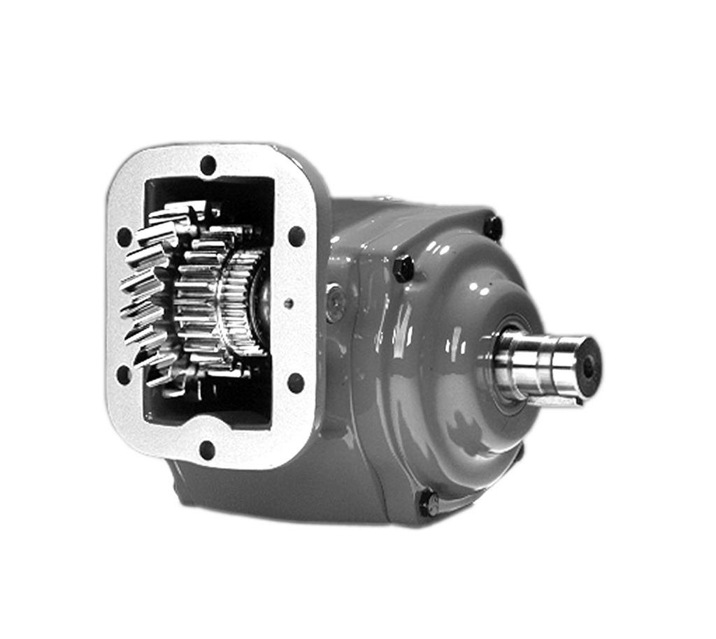
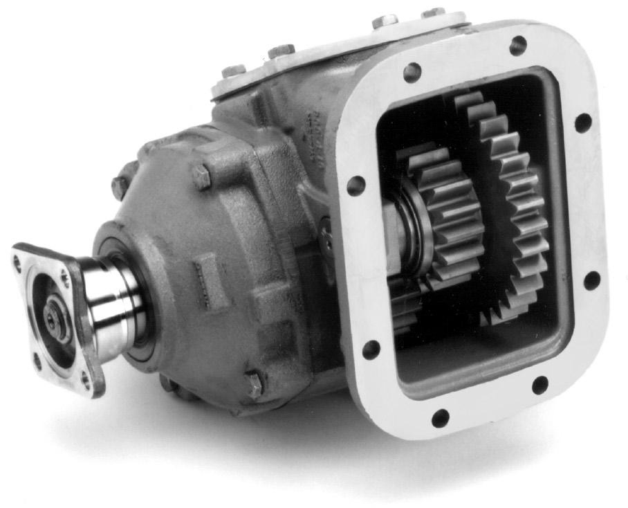
8 General Information 10-Bolt Powershift P.T.O.s Foreword Since our major objective is to show you how to get additional and more profitable miles from truck, tractor and trailer components, we want to provide you with information on the installation of Chelsea Power Take-Offs. We all realize that an inadequate transmission will overwork any Power Take-Off in a very short period of time. In addition, a mismatched transmission/p.t.o. combination can result in unsatisfactory performance of the equipment right from the start. Before you order new trucks, be sure you re getting the right transmission/p.t.o. combination. It is of vital importance for efficient performance to have adequate power. To help you select the proper type, size and design of P.T.O. it is advisable to discuss your specific requirements with Chelsea P.T.O. specialists. They know their products and have easy access to manufacturers of equipment, transmissions and Power Take-Offs. They can inform you about everything you need to know about power, at the right time, before you specify components. Exploded View of a Typical Powershift P.t.o. 4
9 Installation Instructions 10-Bolt Powershift P.T.O.s Chelsea P.T.O. Safety Label Instructions 1. The two black and orange on white 5" x 7" pressure sensitive vinyl labels, part number ; must be placed on the vehicle frame rails (one (1) on each side), in a position that would be HIGHLY visible to anyone that would go under the truck near the P.T.O. rotating shaft. If the vehicle is to be painted after these labels are installed, cover them with two (2) blank masking covers. Remove the masking covers after painting. 2. Place the one (1) black and orange on white 3.5" x 5" pressure sensitive vinyl label, part number , on the visor nearest the operator of the vehicle, this must be placed near the P.T.O. visor label. 3. Place the one (1) red and white with black lettering 3.5" x 7.5" pressure sensitive vinyl label, part number , on the opposite side of the visor from the above label # Place the one (1) white and black heavy duty card, part number , in the vehicle glove box. Again in a position highly visible to the operator, for example: try to place this card on top of whatever may be in the glove box. If you require labels, please order part number X at no charge from your local Chelsea Warehouse or send request direct to: 8225 Hacks Cross Road Olive Branch, MS Customer Service: (662)
10 Installation Instructions 10-Bolt Powershift P.T.O.s 7 6
11 Installation Instructions 10-Bolt Powershift P.T.O.s Function of Auxiliary Power Shafts An auxiliary power shaft transmits torque from the power source to the driven accessory. The shaft must be capable of transmitting the maximum torque and R.P.M. required of the accessory, plus any shock loads that develop. An auxiliary power shaft operates through constantly relative angles between the power source and the driven accessory, therefore, the length of the auxiliary power shaft must be capable of changing while transmitting torque. This length change, commonly called slip movement, is caused by movement of the power train due to torque reactions and chassis deflections. Joint operating angles are very important in an auxiliary power joint application. In many cases, the longevity of a joint is dependent on the operating angles. (See chart below) This information is limited to 1000 through 1310 series applications. For applications requiring a series larger than 1310, contact your local Chelsea distributor. Determining Shaft Type 1) Solid or tubular? a) In applications requiring more than 1000 R.P.M. or where the application necessitates a highly bal anced auxiliary power shaft, a tubular shaft should be used. b) Spicer s solid shafting auxiliary power joints are designed for 1000 or less R.P.M. intermittent service such as: Driving small hydraulic pumps Driving winches Driving low speed product pumps 2) Joint Series should be determined using the chart on the following page. Spicer Universal Joint Operating Angles Prop. Max. Normal Prop. Max. Normal Shaft R.P.M. Operating Angle Shaft R.P.M. Operating Angle ' ' ' ' ' ' Above based on angular acceleration of 100 RAD/SEC 2 7
12 Installation Instructions 10-Bolt Powershift P.T.O.s Spicer Universal Joint Engineering Data Joint Series Torque Rating Automotive (Gas or Diesel Engine) Lbs. ft. Continuous Tubing Diameter Wall Thickness W = Welded S = Seamless W S W W Flange Diameter (Swing Diameter) Rectangular Type Bolt Holes - Flange Yoke Circle Diameter Number Male Pilot Dia Distance Across Lugs Snap Ring Construction Bearing Diameter Maximum Operating Speed * By Tube Size, Solid Shaft Size, and Length *(For speed below 500 R.P.M. or over 2500 R.P.M., contact your Chelsea Distributor) Tubing Dia. & Wall Thickness Joint & Shaft (W=Welded S=Seamless) Max. Installed Length in Inches for Given R.P.M. Centerline to Centerline of Joints for a Two Joint Assembly or Centerline of Joint to Centerline of Center Bearing for a Joint & Shaft R.P.M. - Revolutions per Minute " X.065" W 117" 82" 67" 58" 52" 1.250" X.095" S 91" 64" 52" 45" 40" 2.500" X.083" W 122" 87" 70" 62" 55" 3.000" X.083" W " 76" Solid Shaft Diameter.750" 60" 42" 35" 30" 27".812" 62" 44" 36" 31" 28".875" 65" 46" 37" 32" 29" 1.000" 69" 49" 40" 35" 31" 1.250" 77" 55" 45" 39" 35" 8

 of Transmission. Fig. 1 2. Remove the P.T.O. aperture plate with a 15mm socket (Fig.")

 (Refer to Page 35 for correct location and use).")
13 Installation Instructions Allison World Transmission P.T.O.s Mounting the P.t.o. on the Transmission When installing a P.T.O., always wear protective clothing and safety glasses. 1. Begin by draining the oil from the transmission. Use caution, since the oil may be hot (Fig. 1). NOTE: Installation shown is for Right Side (Street Side) of Transmission. Fig Remove the P.T.O. aperture plate with a 15mm socket (Fig. 2). Fig Remove the gasket and clean the aperture surface (Fig. 3). NOTE: Do not reuse the gasket that comes with the transmission. Fig Using a screwdriver, install the guide pins until they bottom out (Fig. 4) (Refer to Page 35 for correct location and use). NOTE: Do not use sealing compounds because they are generally incompatible with automatic transmission fluid. Fig. 4 9


 (Fig. 7). Fig. 7 8.")
14 Installation Instructions Allison World Transmission P.T.O.s Mounting the P.t.o. on the Transmission (Continued) 5. Install the special gasket over the guide pins. The ribbed surface should face outward, toward the installer (Fig. 5). NOTE: To insure proper backlash and sealing of P.T.O. to transmission only use gasket furnished with the P.T.O. Fig Position the P.T.O. and secure it with the top capscrew (Fig. 6). Note: Refer to page 35 for proper capscrew installation for the 269 & 278 Series Fig Install the remaining capscrews. Torque all to Lbs. ft. (54-68 N.m. or Kg.m) (Fig. 7). Fig Install PTO pressure switch, part # , into port on Hydraulic Valve Cap. Torque to In-lbs (Fig. 8). Fig. 8 10
 9.")
.")


 12.")
15 Bulletin HY M1/US Installation Instructions Allison World Transmission P.T.O.s Mounting the P.T.O. on the Transmission (Continued) 9. If using a rotatable flange see page 35 for bolt torque specifications. (Fig. 9). Fig Securely attach the high pressure line to the P.T.O. valve (Fig. 10). Fig Use the special fitting to securely attach the high pressure line to the transmission. This fitting is included with the P.T.O. (Fig. 11). See the chart on page 12 for the correct hose specifications. With the hose and P.T.O. securely connected, refill the transmission to the manufacturer s suggested specifications. Fig. 11 (Right side shown) 12. Complete the assembly by installing the electrical connection to the valve assembly (Fig. 12) and the pressure switch (Fig 13). Fig. 12 Fig
16 Installation Instructions Allison World Transmission P.T.O.s Pressure Port and Aperture Opening Identification 1. These drawings represent left and right views of the MD and HD pressure ports on the transmission [257.8] MD Top/Left Main Pressure Port UNF-2A 175 to 255 P.S.I. Both Sides [618.0] 83-Teeth Main Pressure Port UNF-2A 175 to 255 P.S.I. Both Sides Allison10-Bolt Pad [257.8] MD Right/Left Main Pressure Port UNF-2A 175 to 255 P.S.I. Both Sides Allison10-Bolt Pad [618.0] 68-Teeth Main Pressure Port UNF-2A 175 to 255 P.S.I. Both Sides HD Top/Left [345.7] Allison10-Bolt Pad Standard Hose Specifications by Transmission 97-Teeth Main Pressure Port UNF-2A Left Side Only TRANS. LOCATION 267 Series 277 Series 278 Series 859 Series MD Top Right (Right Press. Port) X X X X MD L.H. Side (Left Press. Port) X X X X MD R.H. Side (Right Press. Port) X X X X HD Top Right (Left Press. Port) X X X X HD L.H. Side (Left Press. Port) X X X X HD 1, 2 L.H. Side (Left Press. Port) X X X HD 1, 2 Top Right (Right Press. Port) X X X MD 1, 2 L.H. Side (Left Press. Port) X X X MD 1, 2 R.H. Side (Right Press. Port) X X X An HD with 2 P.T.O. s requires a T fitting and a swivel nut 90 degree elbow to attach 2 hoses to the single port on the left side. 1 Lubrication Option R, shifter Options G and H for 277 and 859 Series 2 Lubrication Option R for 278 Series 12
17 Installation Sketch Allison World Transmission P.T.O.s Shift Installation Kit 277, 278 & 859 Series without Electronic Overspeed Control (SK-347 Rev C) (Old Style) X 12V Installation Kit X 24V Installation Kit Valve Connection and Wire Assembly Grommet Drill 1" Dia. Hole in Firewall Red Wire Run Wires Through Grommet in Firewall Blue Wire Black Wire Electrical Ground of Cab or Frame Accepts #10 Screw Red Wire Spade Terminal Red Wire Butt Connector Indicator Light White Switch Volt Volt Pressure Switch Bracket Fuse Holder 10 Amp Fuse See Hose Chart page Fitting Install in Transmission High Pressure Port MD: Left or Right Side HD: Left Side Only Splice Connector Positive Terminal of Ignition or Battery "R" Lubrication Option 278 Series 13
18 Installation Sketch Allison World Transmission P.T.O.s Shift Installation Kit 277, 278 & 859 Series without Electronic Overspeed Control (SK-347 Rev D) (New Style) X 12V Installation Kit X 24V Installation Kit Valve Connection and Wire Assembly Red Wire Grommet Drill 1" Dia. Hole in Firewall Run Wires Through Grommet in Firewall Blue Wire Black Wire Electrical Ground of Cab or Frame Accepts #10 Screw Red Wire Spade Terminal Red Wire Butt Connector Indicator Light White Switch Volt Volt Pressure Switch Fuse Holder 10 Amp Fuse Bracket See Hose Chart page Fitting Install in Transmission High Pressure Port MD: Left or Right Side HD: Left Side Only Splice Connector Positive Terminal of Ignition or Battery "R" Lubrication Option 278 Series 14
19 Installation Sketch Allison World Transmission P.T.O.s Shift Installation Kit 277, 278 & 859 Series with Electronic Overspeed Control (SK-348 Rev B) (Old Style) X Installation Kit Ground to Cab or Frame Grommet Positive Terminal of Ignition or Battery Drill 1" Dia. Hole in Firewall Run Wires Through Grommet in Firewall Accepts.25" Screw 9 Amp Fuse Holder Blue Wire Red Wire Green Wire Chelsea Speed Limiter X X 28-P-171 O-Ring Speed Sensor Run Cable Through Grommet in Firewall Speed Sensor Extension Cable X (10 ft. Supplied w/e.o.c.) X (5 ft. Optional Cable) Valve Connection and Wire Assembly Accepts #10 Screw Electrical Ground of Cab or Frame Black Wire Pressure Switch Fitting MD-Left or Right Side HD-Left Side Only See Hose Chart Page 12 "R" Lubrication Option 278 Series 15
20 Installation Sketch Allison World Transmission P.T.O.s Shift Installation Kit 277, 278 & 859 Series with Electronic Overspeed Control (SK-348 Rev C) (New Style) X Installation Kit Drill 1" Dia. Hole in Firewall Ground to Cab or Frame Accepts.25" Screw Grommet Positive Terminal of Ignition or Battery Run Wires Through Grommet in Firewall Blue Wire 9 Amp Fuse Holder Red Wire Green Wire Chelsea Speed Limiter X X 28-P-171 O-Ring Speed Sensor Run Cable Through Grommet in Firewall Speed Sensor Extension Cable X (10 ft. Supplied w/e.o.c.) X (5 ft. Optional Cable) Valve Connector and Wire Assembly Accepts #10 Screw Electrical Ground of Cab or Frame Black Wire Pressure Switch Fitting MD-Left or Right Side HD-Left Side Only See Hose Chart Page 12 "R" Lubrication Option 278 Series 16
21 Installation Sketch Allison World Transmission P.T.O.s Shift Installation Kit 277, 278, & 859 Series with Remote Mount Solenoid (SK-432 Rev B) X 12V Installation Kit X 24V Installation Kit Accepts #10 Screw Black Wire Grommet Drill 1" Dia. Hole in Firewall Run Wires Through Grommet in Firewall Run Tee Oil from Trans Adapter Mounting Bracket Electrical Ground of Cab or Frame V Solenoid Valve V Solenoid Valve Adapter Butt Connector 2x Lock washer Pressure Switch Oil to P.T.O. Clutch 21-P-701 Slice Grommet Insert in Hole in Firewall X Valve Connector and Wire Assembly X Green Wire Spade Terminal X Hose Assembly Tee Fitting Swivel Union Switch Blue Wire Bracket Butt Connector V Indicator Light V Indicator Light X Hose Ass y 2x Mounting Screw Fitting Oil to P.T.O. Lube X Hose Assembly Fuse Holder Ass y w/10 Amp Fuse Splice Connector Hose Per Chart (See Chart on Page 12) Fitting Install in Transmission High Pressure Port MD-Left or Right Side HD-Right Side Only Torque to Lbs. ft. Torque to In. Lbs. Positive Terminal of Ignition or Battery Note: This option is not available with nor can it be used on E.O.C. applications. 17
22 Installation Sketch Allison World Transmission P.T.O.s Shift Installation Kit 277 Series with Remote Mount Solenoid for Hino Model 338 (SK-410 Rev B) X 12V Installation Kit X 24V Installation Kit X Pressure Switch Relocation Kit (Hino) Accepts #10 Screw Black Wire Grommet Electrical Ground of Cab or Frame Butt Connector Adapter Drill 1" Dia. Hole in Firewall Run Wires Through Grommet in Firewall Butt Connector Switch Spade Terminal Fuse Holder Assembly w/10 AMP Fuse Bracket Splice Connector Positive Terminal of Ignition or Battery X Hose Assembly See Hose Chart Page Fitting Pressure Switch Tee Fitting v Solenoid Valve v Solenoid Valve X Hose Assembly Adapter X Hose Assembly Screws X Hose Assembly Lock Washer O-Ring Hex socket plug Fitting Install in Transmission High Pressure Port 18
23 GMT P.T.O. Connector Allison World Transmission P.T.O.s GMT C Series Trucks For model year 2003 GM C Series 4500, 5500, 6500, 7500 and 8500 trucks may be equipped with the Allison World (MD) transmission. In these vehicles GM Truck has integrated a P.T.O. connector, located in the right hand engine compartment area. A Power Take-Off switch has also been incorporated into the GM dash panel to control P.T.O. operation. With the P.T.O. option ordered on the truck, the P.T.O. connector and in-dash switch simplify the interface for the body builder. In order for the customer to utilize the full capability of the P.T.O./transmission, Chelsea has design a wiring harness that must be used between the GM P.T.O. connector and the Chelsea Power Take-Off. These are for P.T.O. Non E.O.C. applications only. On the Allison World (MD) transmission the P.T.O. drive gear is engine driven. The wiring harness is not required for the Power Take-Offs listed on the chart, but must be used if the GM supplied in-dash P.T.O. switch is to be utilized. See wiring harness part number for the 277, 278 and 859 Series Power Take-Offs GM C Series Wiring Harness for 277, 278 and 859 Series Part Number ' 6" Connect to Solenoid Valve Black Wire Loom Connect to Pressure Switch To GM P.T.O. Connector 19
24 Installation Sketch Allison World Transmissions P.T.O. Combo Valve Installation Sketch, 277/278 Series (SK-427 Rev B) (Old Style) Grommet Slice Grommet Insert in Hole in Firewall Red Wire Drill 1" Dia. Hole in Firewall Run Wires Through Grommet in Firewall Butt Connector Valve Connector and Wire Assembly Allison P.T.O. Shown Black Wire Pressure Switch Electrical Ground of Cab or Frame Fitting Install in Transmission High Pressure Port MD: Left or Right Side HD: Left Side Only Accepts #10 Screw Spade Terminal Blue Wire Fuse Holder Ass y w/10 Amp Fuse Splice Connector Red L.E.D. 12 Volt Indicator Light Assembly X Pressure Switch To P.T.O. Port Air Control Valve Female Connector Hose Per Chart (See Chart on Page 12) Positive Terminal of Ignition or Battery Hose Per Chart (See Chart on Page 12) Installation Kits X S Shifter X T Shifter Pressure Protection Valve Opens at 40 PSI Cab R Lubrication Option Red L.E.D. 12 volt Indicator Light Assembly Hex Nipple Male Connector Nylon Tubing Air Supply /4" Nylon Tubing Male Connector To Dump Pump Shifter Lower Port Female Connector Pressure Switch Male Connector To Dump Pump Shifter Raise Port Warning: Connect directly to air supply. Do not use tubing between air supply and pressure protection valve. Caution: When installing nylon tubing avoid sharp angles, exhaust and manifold systems. 20
25 Installation Sketch Allison World Transmissions P.T.O. Combo Valve Installation Sketch, 277/278 Series (SK-427 Rev C) (New Style) Grommet Slice Grommet Insert in Hole in Firewall Red Wire Drill 1" Dia. Hole in Firewall Run Wires Through Grommet in Firewall Butt Connector Electrical Ground of Cab or Frame Valve Connector and Wire Assembly Black Wire Accepts #10 Screw Blue Wire Spade Terminal Allison P.T.O. Shown Pressure Switch Fitting Install in Transmission High Pressure Port MD: Left or Right Side HD: Left Side Only Fuse Holder Ass y w/10 Amp Fuse Splice Connector X Pressure Switch Female Connector To P.T.O. Port Air Control Valve Red L.E.D. 12 Volt Indicator Light Assembly Positive Terminal of Ignition or Battery Installation Kits X S Shifter X T Shifter Hex Nipple Hose Per Chart (See Chart on Page 12) Pressure Protection Valve Opens at 40 PSI Male Connector Cab R Lubrication Option Hose Per Chart (See Chart on Page 12) Red L.E.D. 12 volt Indicator Light Assembly Air Supply Nylon Tubing /4" Nylon Tubing Female Connector Male Connector To Dump Pump Shifter Lower Port Pressure Switch Male Connector To Dump Pump Shifter Raise Port Warning: Connect directly to air supply. Do not use tubing between air supply and pressure protection valve. Caution: When installing nylon tubing avoid sharp angles, exhaust and manifold systems. 21

.")
 (see page 35).")

26 Installation Instructions Caterpillar Mounting the P.t.o. on the Transmission When installing a P.T.O., always wear protective clothing and safety glasses. 1. Remove the P.T.O. aperture plate with a 16mm socket (Fig. 1). Fig Remove the gasket and clean the aperture surface (Fig. 2). NOTE: Do not reuse the gasket that comes with the transmission. Fig Using a screwdriver, install the guide pins until they bottom out (Fig. 3) (see page 35). NOTE: Do not use sealing compounds because they are generally incompatible with automatic transmission fluid. Fig Install the special gasket over the guide pins. The ribbed surface should face outward, toward the installer (Fig. 4). NOTE: To insure proper backlash and sealing of the P.T.O. to the transmission, only use Gasket furnished with the P.T.O. Fig. 4 22

. Fig.")

 to securely attach the high pressure line to the transmission.")
27 Installation Instructions Caterpillar Mounting the P.t.o. on the Transmission (Continued) 5. Position the P.T.O. and secure it with the top capscrew provided. (Fig. 5) Note: Refer to page 35 for proper capscrew installation for the 269 & 278 Series Fig Install the remaining capscrews. Torque them to Lbs. ft. [50-60 N.m.] (Fig. 6). Fig. 6 NOTE: There are two (2) high pressure ports available. Use the port located on the driver s side of the transmission unless there is an interference issue with a pump or driven object (Fig. 7). Fig Using the special fitting (379812) to securely attach the high pressure line to the transmission. This fitting is included with the P.T.O. Tighten to 8-10 Lbs. ft. [ N.m.] (Fig. 8). See the hose chart on page 28 for the correct hose specifications. Tighten hose end fitting 2 flats from finger tight Fig. 8 23
. Fig. 9 9. Complete the assembly by installing the electrical connection (Fig. 10). NOTE: See page 25-27 for electrical connection drawings.")
28 Installation Instructions Caterpillar Mounting the P.T.O. on the Transmission (Continued) 8. Securely attach the high pressure line to the valve. Tighten hose end fitting 2 flats from finger tight (Fig. 9). Fig Complete the assembly by installing the electrical connection (Fig. 10). NOTE: See page for electrical connection drawings. NOTE: If using a rotatable flange, see page 35 for bolt torque. Fig
29 Installation Instructions Caterpillar Shift Installation Kit 277, 278 and 859 Series Without Electronic Overspeed Control (SK-411 Rev A) X - For 12V Installation Kit X - For 24V Installation Kit Valve Connector and Wire Assembly This Hose Purchased Separately See Hose Chart SK-414 page Grommet Drill 1" Dia. Hole In Firewall Slice Grommet, Insert in Hole in Firewall Run Wires Through Grommet in Firewall Red Wire Black Wire Electrical Ground of Cab or Frame Pressure Switch Torque Values must be between lbs. in. Blue Wire Spade Terminal Switch Butt Connector Volt Indicator Light Volt Indicator Light Bracket Fuse Holder w/ 10 amp Fuse Torque to Lbs. ft Splice Connector Positive Terminal of Ignition or Battery Straight Fitting Install in Transmission High Pressure Port 25
30 Installation Instructions Caterpillar Electronic Overspeed Control Installation Sketch for 277, 278 and 859 Series (SK-412 Rev A) X Installation Kit Electrical Ground of Cab or Frame Splice Connector Positive Terminal of Ignition or Battery Grommet Slice Grommet Insert In Hole In Firewall Drill 1" Dia. Hole in Firewall Run Wire Through Grommet in Firewall Accepts.25" Screw Fuse Holder w/ 9 AMP Fuse (Part of E.O.C.) Blue Wire Blue Wire Red Wire Green Wire Chelsea Speed Limiter X 12 volt X 24 volt Speed Sensor Extention Cable X (10 ft. Supplied w/ E.O.C.) X (5 ft. Optional Cable) Hose Purchased Separately See Hose Chart SK-414 page 28 Run Cable Through Grommet in Firewall Valve Connector and Wire Assembly Black Wire Accepts #10 Screw Electrical Ground of Cab or Frame Torque to Lbs. ft Pressure Switch Torque Between Lb.in Straight Fitting Install In Transmission High Pressure Port 26
31 Installation Instructions Caterpillar Remote Mount Installation Sketch for 277, 278 and 859 (SK-413 Rev C) X 12V Installation Kit X 24V Installation Kit Accepts #10 Screw Black Wire Grommet Drill 1" Dia. Hole in Firewall Swivel Nut Run Tee Electrical Ground of Cab or Frame Slice Grommet Insert in Hole in Firewall Blue Wire Valve Connector and Wire Assembly Run Wires Through Grommet in Firewall Butt Connector Oil from Trans Connector Connector Valve Exhaust Red Wire Pressure Switch Tee Fitting Spade Terminal Switch Remote Valve Assembly X - 12 Volt X - 24 Volt Elbow Union Swivel Nut X Oil to P.T.O. Lube Hose Ass y Purchase Separately Connector X Oil to P.T.O. Clutch Hose Ass y Purchased Separately 21-P Fuse Holder Assembly w/10 AMP Fuse Bracket Purchased Separately See Hose Chart SK-414 page X Hose Assembly Purchase Separately Straight Fitting Install in Transmission High Pressure Port Torque to In. Lbs Splice Connector Positive Terminal of Ignition or Battery Volt Indicator Light Volt Indicator Light Note: This option is not available with, nor can it be used on E.O.C. applications. Torque to Lbs. ft. 27
32 Installation Instructions Caterpillar Pressure Port Locations & Hose Chart (SK-414 Rev B) Left Side Port Rear Port Left Side Port Rear Port CX31 CX28 (Filter Removed for Clarity) Both High Pressure Connections are -4 O-Ring Boss HOSE CHART Trans. P.T.O. P.T.O. High Oil P.T.O. P.T.O. Trans. Trans.-P.T.O. Location Pressure Valve Fitting Fitting Valve Hose # Location Location Driver (LHS) LHS X Driver (LHS) Rear X Attached Pass. (RHS) LHS X 277, 278 Pass. (RHS) Rear X 859 Driver (LHS) LHS X Driver (LHS) Rear X Remote Pass. (RHS) LHS X CX31 Pass. (RHS) Rear X CX28 Driver (LHS) LHS X 267 Driver (LHS) Rear X N/A Pass. (RHS) LHS X Pass. (RHS) Rear X Driver (LHS) LHS X 867 Driver (LHS) Rear X N/A Pass. (RHS) LHS X Pass. (RHS) Rear X LHS = Left Side of Transmission, 8 o clock position RHS = Right Side of Transmission, 1 o clock position NOTES: 1. P.T.O. Fitting and Transmission Fitting included with the P.T.O. Unit. If Using in Transmission it Must be Purchased Separately 2. Hoses to be Purchased Separately Elbow Will Not Install on Left Hand (Driver) Side Oil Port Due to Transmission Interference 4. If is Listed as Transmission Fitting for Rear Location, Route Hose Along Right Hand (passenger) Side of Transmission and Under Transmission Output Yoke 28
33 Installation Sketch 10-Bolt Powershift P.T.O.s CAUTION: Wet Spline Options Must be used with a Pump that has a Contiguous Sealing surface to Ensure a proper seal between Pump and P.T.O. Installation RY Wet 267 Series (SK-351 Rev C) Install 22-P-84 gasket between P.T.O. and Pump. Install 22-P-100 gasket between bearing cap & output flange on P.T.O X Connect to transmission pressure port. Hose must be ordered separately. See hose charts on page 28 for Caterpillar and page 30 for Allison. Installation AF Wet Spline 267 Series (SK-350 Rev C) Install 35-P-92 gasket between P.T.O. and Pump X Connect to transmission pressure port. Hose must be ordered separately. See hose charts on page 28 for Caterpillar and page 30 for Allison. 29
34 Installation Sketch 10-Bolt Powershift P.T.O.s Installation AK Wet Spline 267 Series (SK-378 Rev A) 3 Ass y View X Hose Assembly Restrictor Connect to Transmission Pressure Port See Charts on page 28 for Caterpillar and page 30 for Allison Elbow Install 35-P-95 Gasket between P.T.O. & pump Kit #329406X for Wet Spline Installation Components 5 Ass y View Install 35-P-95 Gasket between P.T.O. & pump Connect to Transmission Pressure Port See Charts on page 28 for Caterpillar and page 30 for Allison Elbow X Hose Assembly Restrictor Pressure Hose Chart (Transmission to P.T.O.) Trans Location Hose MD Left X MD Right X HD Left X HD Top Right X 30
35 Installation Sketch 10-Bolt Powershift P.T.O.s Installation AF Wet Spline 277 & 278 Series (SK-383 Rev B) (Old Style) 28-P-259 O-Ring Pipe Adapter See Hose Chart Male Branch Tee Connect To Tee on Output Flange Connect to Tee on Valve Cover X Hose Assembly NWD PAT. Output Side Valve Cover Side Pipe Plug X - Wet Spline Installation Kit Pressure Hose Chart (Transmission to P.T.O.) Trans Location Hose MD Left X MD Right X HD Left X HD Right X 31
36 10-Bolt Powershift P.T.O.s Bulletin HY M1/US Installation Sketch Installation AF Wet Spline 277 & 278 Series (SK-383 Rev D) (New Style) Pipe Adapter See Hose Chart 28-P-259 O-Ring Male Branch Tee Connect to Tee on Valve Cover NWD PAT. Connect To Tee on Output Flange X Hose Assembly Valve Cover Side Output Side Pressure Hose Chart (Transmission to P.T.O.) Trans Location Hose MD Left X MD Right X HD Left X HD Right X 32
37 Installation Sketch 10-Bolt Powershift P.T.O.s Installation XY Wet Spline 269 Series (SK-416 Rev B) X Lube Hose Elbow Adapter w/restriction Tee Connect to Transmission Pressure Port See Chart for Hose Lengths Install 22-P-84 Gasket Between P.T.O. and Pump (Part of X) Fitting to Transmission Pressure Tap Hose - See Chart Order Separately Fitting to P.T.O. 90 Fitting Pressure Hose Chart (Transmission to P.T.O.) Trans Location Hose MD Left X MD Right X HD Left X HD Top Right X 33
38 Installation Sketch 10-Bolt Powershift P.T.O.s Installation ZY Wet Spline 277 & 278 Series (SK-454 Rev A) Adapter w/restriction Elbow Tee Connect to Transmission Pressure Port See Chart for Hose Lengths Install 22-P-84 Gasket Between P.T.O. and Pump X Lube Hose (Part of X) Fitting to Transmission Pressure Tap Hose - See Chart Order Separately 90 Fitting Fitting to P.T.O. Pressure Hose Chart (Transmission to P.T.O.) Trans Location Hose MD Left X MD Right X HD Left X HD Right X 34
39 Bulletin HY M1/US Installation Instructions 10-Bolt Powershift P.T.O.s 269 & 278 Series Installation Mounting Kit Instructions (SK-355 Rev B) Dowel Pin Location if installing P.T.O. on Right Side (Street Side) of Transmission. Dowel Pin Locations if installing P.T.O. on Left Side (Curb Side) of Transmission. NOTE: P.T.O. Models 269 & 278 Guide pins may be removed after assembly and replaced with capscrews. NOTE: Models 267, 277, 859 & 867 guide pins cannot be removed. NOTE: Install Shorter capscrews Under Barrel of P.T.O. Housing in Either Hole Depending on Housing Orientation. Installing Rotatable Flanges The rotatable flange is shipped loose with the P.T.O. units for ease of installation. After determining the flange position, attach the flange to the P.T.O. bearing cap using the capscrews provided in the bag kit. Bag kit number X (6-bolt family) will contain (3) capscrews ( ) and X (277 Series) will contain (4) capscrews for attaching the flange to the P.T.O. bearing cap. After installing the capscrews make sure to torque the screws to Lbs. ft. Consideration should be taken on the size and weight of the pump being installed. (see pages 3 and 4) RA Flange Shown NOTE: Reinstalling or tightening of a rotatable flange after it has become loose is not recommended. If a P.T.O. has run for a length of time after the flange has become loose, the flange and / or bearing cap may not be to manufacturing tolerance. 35
40 Installation Instructions 10-Bolt Powershift P.T.O.s P.t.o. Shifting Procedure & Precautions CAUTION: This vehicle is equipped with a Power Take-Off. Shut engine off before working on the Power Take-Off or getting below the vehicle. Consult the operating instructions before using the P.T.O. (See sun visor.) POWER TAKE-OFF OPERATION VEHICLE STATIONARY Automatic Transmission with Powershift P.T.O.s Engage the P.T.O. with the engine at idle speed. NOTE: Powershift P.T.O.s: The engine must be at idle or below 1000 R.P.M. when the P.T.O. is engaged. See the transmission manufacturer s instructions for special procedures. IMPORTANT: Failure to follow the proper shifting or operating sequences will result in premature P.T.O. failure with possible damage to other equipment. Warning: Cold Weather Operation of Powershift P.T.O.s During extreme cold weather operation [32 F (0 C) and lower], a disengaged Powershift Power Take-Off can momentarily transmit high torque that will cause unexpected output shaft rotation. This is caused by the high viscosity of the transmission oil when it is extremely cold. As slippage occurs between the Power Take-Off clutch plates, the oil will rapidly heat up and the viscous drag quickly decreases. The Power Take-Off output shaft rotation could cause unexpected movement of the driven equipment, resulting in serious personal injury, death, or equipment damage. To avoid personal injury or equipment damage: Driven equipment must have separate controls. Driven equipment must be left in the disengaged position when not in operation. Driven equipment must not be operated until the vehicle is allowed to warm up. This symbol warns of possible personal injury. 36
41 Notes 37
42 Power Take-Off Maintenance 10-Bolt Powershift P.T.O.s Power Take-Off Maintenance Due to the normal and sometime severe torsional vibrations that Power Take-Off units experience, operators should follow a set maintenance schedule for inspections. Failure to service loose bolts or Power Take-Off leaks could result in potential auxiliary Power Take-Off or transmission damage. Periodic P.T.O. MAINTENANCE is required by the owner/operator to ensure proper, safe and trouble free operation. Daily: Check all air, hydraulic and working mechanisms before operating P.T.O. Perform maintenance as required. Monthly: Inspect for possible leaks and tighten all air, hydraulic and mounting hardware, if necessary. Torque all bolts, nuts, etc. to Chelsea specifications. Insure that splines are properly lubricated, if applicable. Perform maintenance as required. With regards to the direct mounted pump splines, the P.T.O. requires the application of a specially formulated anti-fretting, high pressure, high temperature grease. The addition of the grease has been proven to reduce the effects of the torsional vibrations, which result in fretting corrosion on the P.T.O. internal splines as well as the pump external splines. Fretting corrosion appears as a rusting and wearing of the pump shaft splines. Severe duty applications, which require long P.T.O. running times and high torque may require more frequent regreasing. Applications such as Utility Trucks that run continuously and are lightly loaded also require frequent regreasing due to the sheer hours of running time. It is important to note that service intervals will vary for each and every application and is the responsibility of the end user of the product. Chelsea also recommends that you consult your pump owners manuals and technical services for their maintenance guidelines. Fretting corrosion is caused by many factors and without proper maintenance; the anti-fretting grease can only reduce its effects on components. Chelsea offers the grease to our customers in two packages. The first is a 5/8 fluid ounce tube (379688), which is included with every applicable P.T.O., and the second is a 14-ounce grease cartridge (379831). Chelsea also offers greaseable shafts for most all output designators. Warranty: Failure to comply entirely with the provisions set forth in the appropriate will result in voiding of ALL Warranty consideration. 38
43 Offer of Sale The items described in this document and other documents or descriptions provided by, its subsidiaries and its authorized distributors are hereby offered for sale at prices to be established by, its subsidiaries and its authorized distributors. This offer and its acceptance by any customer ("Buyer") shall be governed by all of the following Terms and Conditions. Buyer s order for any such items, when communicated to, its subsidiary or an authorized distributor ("Seller") verbally or in writing, shall constitute acceptance of this offer. 1. Terms and Conditions of Sale: All descriptions, quotations, proposals, offers, acknowledgments, acceptances and sales of Seller s products are subject to and shall be governed exclusively by the terms and conditions stated herein. Buyer s acceptance of any offer to sell is limited to these terms and conditions. Any terms or conditions in addition to, or inconsistent with those stated herein, proposed by Buyer in any acceptance of an offer by Seller, are hereby objected to. No such additional, different or inconsistent terms and conditions shall become part of the contract between Buyer and Seller unless expressly accepted in writing by Seller. Seller s acceptance of any offer to purchase by Buyer is expressly conditional upon Buyer s assent to all the terms and conditions stated herein, including any terms in addition to, or inconsistent with those contained in Buyer s offer, Acceptance of Seller s products shall in all events constitute such assent. 2. Payment: Payment shall be made by Buyer net 30 days from the date of delivery of the items purchased hereunder. Amounts not timely paid shall bear interest at the maximum rate permitted by law for each month or portion thereof that the Buyer is late in making payment. Any claims by Buyer for omissions or shortages in a shipment shall be waived unless Seller receives notice thereof within 30 days after Buyer s receipt of the shipment. 3. Delivery: Unless otherwise provided on the face hereof, delivery shall be made F.O.B. Seller s plant. Regardless of the method of delivery, however, risk of loss shall pass to Buyer upon Seller s delivery to a carrier. Any delivery dates shown are approximate only and Seller shall have no liability for any delays in delivery. 4. Warranty: Seller warrants that the items sold hereunder shall be free from defects in material or workmanship for a period of: (A) All Power Take-Off units 18 months from date of sale. (B) Except 267, 269, 277, 278, 246, 247, 250, and 859 series two (2) years from date of installation. THIS WARRANTY COMPRISES THE SOLE AND ENTIRE WARRANTY PERTAINING TO ITEMS PROVIDED HEREUNDER. SELLER MAKES NO OTHER WARRANTY, GUAR- ANTEE, OR REPRESENTATION OF ANY KIND WHATSOEVER. ALL OTHER WARRANTIES, INCLUDING BUT NOT LIMITED TO, MERCHANTABILITY AND FITNESS FOR PURPOSE, WHETHER EXPRESS, IMPLIED, OR ARISING BY OPERATION OF LAW, TRADE USAGE, OR COURSE OF DEALING ARE HEREBY DISCLAIMED. NOTWITHSTANDING THE FOREGOING, THERE ARE NO WARRAN- TIES WHATSOEVER ON ITEMS BUILT OR ACQUIRED WHOLLY OR PARTIALLY, TO BUYER S DESIGNS OR SPECIFICATIONS. 5. Limitation Of Remedy: SELLER S LIABILITY ARISING FROM OR IN ANY WAY CONNECTED WITH THE ITEMS SOLD OR THIS CONTRACT SHALL BE LIMITED EXCLUSIVELY TO REPAIR OR REPLACEMENT OF THE ITEMS SOLD OR REFUND OF THE PURCHASE PRICE PAID BY BUYER, AT SELLER S SOLE OPTION. IN NO EVENT SHALL SELLER BE LIABLE FOR ANY INCIDENTAL, CONSEQUENTIAL OR SPECIAL DAMAGES OF ANY KIND OR NATURE WHATSOEVER, INCLUDING BUT NOT LIMITED TO LOST PROFITS ARISING FROM OR IN ANY WAY CONNECTED WITH THIS AGREEMENT OR ITEMS SOLD HEREUNDER, WHETHER ALLEGED TO ARISE FROM BREACH OF CONTRACT, EXPRESS OR IMPLIED WARRANTY, OR IN TORT, INCLUDING WITHOUT LIMITATION, NEGLIGENCE, FAILURE TO WARN OR STRICT LIABILITY. 6. Changes, Reschedules and Cancellations: Buyer may request to modify the designs or specifications for the items sold hereunder as well as the quantities and delivery dates thereof, or may request to cancel all or part of this order, however, no such requested modification or cancellation shall become part of the contract between Buyer and Seller unless accepted by Seller in a written amendment to this Agreement. Acceptance of any such requested modification or cancellation shall be at Seller s discretion, and shall be upon such terms and conditions as Seller may require. 7. Special Tooling: A tooling charge may be imposed for any special tooling, including without limitation, dies, fixtures, molds and patterns, acquired to manufacture items sold pursuant to this contract. Such special tooling shall be and remain Seller s property notwithstanding payment of any charges by Buyer. In no event will Buyer acquire any interest in apparatus belonging to Seller which is utilized in the manufacture of the items sold hereunder, even if such apparatus has been specially converted or adapted for such manufacture and notwithstanding any charges paid by Buyer. Unless otherwise agreed, Seller shall have the right to alter, discard or otherwise dispose of any special tooling or other property in its sole discretion at any time. 8. Buyer s Property: Any designs, tools, patterns, materials, drawings, confidential information or equipment furnished by Buyer or any other items which become Buyer s property, may be considered obsolete and may be destroyed by Seller after two (2) consecutive years have elapsed without Buyer placing an order for the items which are manufactured using such property, Seller shall not be responsible for any loss or damage to such property while it is in Seller s possession or control. 9. Taxes: Unless otherwise indicated on the face hereof, all prices and charges are exclusive of excise, sales, use, property, occupational or like taxes which may be imposed by any taxing authority upon the manufacture, sale or delivery of the items sold hereunder. If any such taxes must be paid by Seller or if Seller is liable for the collection of such tax, the amount thereof shall be in addition to the amounts for the items sold. Buyer agrees to pay all such taxes or to reimburse Seller therefore upon receipt of its invoice. If Buyer claims exemption from any sales, use or other tax imposed by any taxing authority, Buyer shall save Seller harmless from and against any such tax, together with any interest or penalties thereon which may be assessed if the items are held to be taxable. 10. Indemnity For Infringement of Intellectual Property Rights: Seller shall have no liability for infringement of any patents, trademarks, copyrights, trade dress, trade secrets or similar rights except as provided in this Part 10. Seller will defend and indemnify Buyer against allegations of infringement of U.S. Patents, U.S. Trademarks, copyrights, trade dress and trade secrets (hereinafter Intellectual Property Rights ). Seller will defend at its expense and will pay the cost of any settlement or damages awarded in an action brought against Buyer based on an allegation that an item sold pursuant to this contract infringes the Intellectual Property Rights of a third party. Seller s obligation to defend and indemnify Buyer is contingent on Buyer notifying Seller within ten (10) days after Buyer becomes aware of such allegations of infringement, and Seller having sole control over the defense of any allegations or actions including all negotiations for settlement or compromise. If an item sold hereunder is subject to a claim that it infringes the Intellectual Property Rights of a third party, Seller may, at its sole expense and option, procure for Buyer the right to continue using said item, replace or modify said item so as to make it noninfringing, or offer to accept return of said item and return the purchase price less a reasonable allowance for depreciation. Notwithstanding the foregoing, Seller shall have no liability for claims of infringement based on information provided by Buyer, or directed to items delivered hereunder for which the designs are specified in whole or part by Buyer, or infringements resulting from the modification, combination or use in a system of any item sold hereunder. The foregoing provisions of this Part 10 shall constitute Seller s sole and exclusive liability and Buyer s sole and exclusive remedy for infringement of Intellectual Property Rights. If a claim is based on information provided by Buyer or if the design for an item delivered hereunder is specified in whole or in part by Buyer, Buyer shall defend and indemnify Seller for all costs, expenses or judgments resulting from any claim that such item infringes any patent, trademark, copyright, trade dress, trade secret or any similar right. 11. Force Majeure: Seller does not assume the risk of and shall not be liable for delay or failure to perform any of Seller s obligations by reason of circumstances beyond the reasonable control of Seller (hereinafter Events of Force Majeure ). Events of Force Majeure shall include without limitation, accidents, acts of God, strikes or labor disputes, acts, laws, rules or regulations of any government or government agency, fires, floods, delays or failures in delivery of carriers or suppliers, shortages of materials and any other cause beyond Seller s control. 12. Entire Agreement/Governing Law: The terms and conditions set forth herein, together with any amendments, modifications and any different terms or conditions expressly accepted by Seller in writing, shall constitute the entire Agreement concerning the items sold, and there are no oral or other representations or agreements which pertain there/to. This Agreement shall be governed in all respects by the law of the State of Ohio. No actions arising out of the sale of the items sold hereunder or this Agreement may be brought by either party more than two (2) years after the cause of action accrues. 6/08-P 39
Owner s Manual Power Take-Offs
 Power Take-Offs Effective: April 2007 Supersedes: HY25-1569-M1/US January 2007 CAT-D Series CAT-H Series WARNING FAILURE OR IMPROPER SELECTION OR IMPROPER USE OF THE PRODUCTS AND/OR SYSTEMS DESCRIBED HEREIN
Parts List 885 Series
 Parts List Effective: October 15, 2001 Supersedes: P410-885 Dated September 2000 WARNING FAILURE OR IMPROPER SELECTION OR IMPROPER USE OF THE PRODUCTS AND/OR SYSTEMS DESCRIBED HEREIN OR RELATED ITEMS CAN
Motorized Control Valves
 Motorized Control Valves Gland Connector Sold as Option. See page XX. Reference coil option chart for additional electrical coil offerings. AC control systems industrial boilers water and purification
H1/H1A Series Variable Displacement, Closed Loop Piston Pump
 Hydraulics Variable Displacement, Closed Loop Piston Pump Catalog No. HY13-1591/US WARNING FAILURE OR IMPROPER SELECTION OR IMPROPER USE OF THE PRODUCTS AND/OR SYSTEMS DE- SCRIBED HEREIN OR RELATED ITEMS
Parts List 236 Series
 Parts List Effective: January 15, 2009 Supersedes: HY25-2236-M1/US Dated July 2007 WARNING FAILURE OR IMPROPER SELECTION OR IMPROPER USE OF THE PRODUCTS AND/OR SYSTEMS DESCRIBED HEREIN OR RELATED ITEMS
Parts List 230/231 Series
 Parts List Effective: December 15, 2001 Supersedes: P410-230/231 Dated December 2000 WARNING FAILURE OR IMPROPER SELECTION OR IMPROPER USE OF THE PRODUCTS AND/OR SYSTEMS DESCRIBED HEREIN OR RELATED ITEMS
Maintenance Instruction & Parts List. ERV Series Value Line Rodless Linear Actuator. Bulletin PM-ERV-B/USA
 Bulletin PM-ERV-B/USA Maintenance Instruction & Parts List Revision Date: September 2005 Supersedes: April 2002 ERV Series Value Line Rodless Linear Actuator WARNING FAILURE OR IMPROPER SELECTION OR IMPROPER
Parts List 277/278 Series
 Effective: September 15, 2009 Supersedes: HY25-2277-M1/US June 2009 WARNING FAILURE OR IMPROPER SELECTION OR IMPROPER USE OF THE PRODUCTS AND/OR SYSTEMS DESCRIBED HEREIN OR RELATED ITEMS CAN CAUSE DEATH,
PVD Series Power Valves Stand alone/stackable with modular solenoid pilot system
 PVD Series Power Valves Stand alone/stackable with modular solenoid pilot system PVD Series Power Valves General Description Telepneumatic offers the unique benefits of ceramic slide construction with
HINO PTO INTERFACE PTO INSTALLATION AND OPERATOR S MANUAL KEEP IN VEHICLE. FOR Allison 2500 With CS6B-A67**-S3*H PTO
 KEEP IN VEHICLE READ OPERATING INSTRUCTIONS INSIDE BEFORE OPERATING PTO HINO PTO INTERFACE PTO INSTALLATION AND OPERATOR S MANUAL FOR Allison 2500 With CS6B-A67**-S3*H PTO Muncie Power Products, Inc. Important
Gerotor Pump & Motor zgp06
 zgp Aluminum High Speed, Low Torque Series Catalog HY9-PGG/MGG/US Catalog HY9-PGG/MGG/US General Information The Parker Hannifin Assures: Consistent quality Technical innovation Premier customer service
Owner s Manual Electronic Overspeed Control
 Electronic Overspeed Control Effective: August 2011 Supercedes: HY25-1650-M1/US January 2011 WARNING User Responsibility FAILURE OR IMPROPER SELECTION OR IMPROPER USE OF THE PRODUCTS DESCRIBED HEREIN OR
WARNING THIS SYMBOL WARNS OF PERSONAL INJURY OR DEATH. Page 2
 WARNING ALWAYS READ AND UNDERSTAND THE ENTIRE MANUAL COMPLETELY BEFORE INSTALLATION OR OPERATION OF PTO AND DRIVEN EQUIPMENT INCLUDING THESE WARNINGS AND OPERATOR S INSTRUCTIONS IN SECTION 3! ALWAYS DISENGAGE
Fixed Displacement Gear Pumps
 Fixed Displacement Gear Pumps D/H/HD Series Catalog HY09-D/H/HD/US Table of Contents Series D/H/HD Description Page No. Introduction... 3 General Description... 4 "D" Series Ordering Information.... 5
GM 6.6L Duramax. Up to 90HP Gain. AgDieselSolutions.com
 21700 Module Installation Guide 2017 GM 6.6L Duramax *L5P* Up to 90HP Gain 1-3 MPG Fuel Savings AgDieselSolutions.com Adjustable Switch Female Fuel Pressure Sensor Connector Male Fuel Pressure Sensor Connector
RM SERIES PTO INSTALLATION AND OPERATOR S MANUAL KEEP IN VEHICLE FOR ALLISON TC10 READ OPERATING INSTRUCTIONS INSIDE BEFORE OPERATING PTO
 KEEP IN VEHICLE READ OPERATING INSTRUCTIONS INSIDE BEFORE OPERATING PTO RM SERIES PTO INSTALLATION AND OPERATOR S MANUAL FOR ALLISON TC10 Muncie Power Products, Inc. WARNING! ALWAYS READ AND UNDERSTAND
THIS IS A HIGH PERFORMANCE PRODUCT - USE AT YOUR OWN RISK!!!
 9/15/08 6.6 GM Duramax Aurora 5000 Turbo Installation Guide THIS IS A HIGH PERFORMANCE PRODUCT - USE AT YOUR OWN RISK!!! Do not use this product until you have carefully read the following agreement. This
20250 Module Installation Guide
 20250 Module Installation Guide 2013.5-2017 RAM 6.7L Cummins Up to 90HP Gain 1-3 MPG Fuel Savings AgDieselSolutions.com Adjustable switch connector Power +12 volts (Red wire) & Ground (Black wire) Injector
Owner s Manual Power Take-Offs
 Power Take-Offs Effective: June 2013 Supersedes: HY25-1240-M1/US January 2013 230 Series 231 Series 236 Series 238 Series 270 Series 271 Series 800 Series 852 Series 885 Series WARNING User Responsibility
Parts List 880 Series
 Parts List Effective: August 15, 2006 Supersedes: HY25-2880-M1/US Dated Feb. 15, 2005 WARNING FAILURE OR IMPROPER SELECTION OR IMPROPER USE OF THE PRODUCTS AND/OR SYSTEMS DESCRIBED HEREIN OR RELATED ITEMS
Female Plug. connecting to Fuel Quantity
 **Ag Diesel Solutions recommends replacing the Transorb/Suppressor Diode before the installation of this module*** Red wire = 12V Constant power. Male Plug connecting to Fuel Quantity Valve Black wire
Elgin Hydraulic Clutch-Brake ECB-240, Product Number FORM NO. L F FORM NO. L F-0704
 Elgin Hydraulic Clutch-Brake ECB-20, Product Number 96225 FORM NO. L-20283-F-070 1 FORM NO. L-20283-F-070 In accordance with Nexen s established policy of constant product improvement, the specifications
Helical Hydraulic Rotary Actuators. Series L and T
 Helical Hydraulic Rotary Actuators Catalog HY341000 Operating Technology Industries Served: Agriculture Construction Energy Marine Material Handling Military Mining Truck/Trailer and many others Helac
DODGE CUMMINS Arctic-Heat Grid Relocation Kit
 Installation Manual P/N 07509-350-GRK 2007.5-09 DODGE CUMMINS Arctic-Heat Grid Relocation Kit Installation Instructions P/N 07509-350-GRK GDP Arctic-Heat Grid Heater Installation PLEASE READ ALL INSTRUCTIONS
½ DODGE CUMMINS OEM BYPASS LIFT PUMP KIT Installation Instructions Part #
 29 July 2005 2003-04.5 Dodge Cummins OEM Bypass Lift Pump Kit # 1050227-1 - 2003-04½ DODGE CUMMINS OEM BYPASS LIFT PUMP KIT Installation Instructions Part # 1050227 PLEASE READ ALL INSTRUCTIONS CAREFULLY
LUBRICATOR GUN INSTRUCTIONS-PARTS LIST. 10,000 psi (700 bar) Maximum Delivery Pressure. Detachable-type
 Maximum Delivery Pressure. Detachable-type") INSTRUCTIONS-PARTS LIST 306 460 INSTRUCTIONS This manual contains important warnings and information. READ AND KEEP FOR REFERENCE. Rev. E Supercedes D Detachable-type LUBRICATOR GUN 10,000 psi (700 bar)
INSTRUCTIONS-PARTS LIST 306 460 INSTRUCTIONS This manual contains important warnings and information. READ AND KEEP FOR REFERENCE. Rev. E Supercedes D Detachable-type LUBRICATOR GUN 10,000 psi (700 bar)
II DISTRIBUTION & SUBSTATION TYPE C
 CapCheckIII DISTRIBUTION & SUBSTATION TYPE Ca p a c i t o r C h e c ke r Operating & Instruction Manual 1475 Lakeside Drive Waukegan, Illinois 60085 U.S.A. 847.473.4980 f a x 8 4 7. 4 7 3. 4 9 8 1 w e
EZ-R7 T-Plug. Universal 7-Pin Heavy Duty Plug For Vehicles equipped with 7-Way Trailer Connectors. Installation Instructions and Product Warranty
 EZ-R7 T-Plug Universal 7-Pin Heavy Duty Plug For Vehicles equipped with 7-Way Trailer Connectors Installation Instructions and Product Warranty Professional Installation Required Thank you for purchasing
PMD DRIVER RELOCATION KIT For Chevy 6.5L Diesel Trucks
 - 1 - PMD DRIVER RELOCATION KIT For 1994-1999 Chevy 6.5L Diesel Trucks Part# 1036520 -- Installation Instructions -- PLEASE READ ALL INSTRUCTIONS CAREFULLY BEFORE INSTALLATION. - 2 - Kit Contents BD P/N#
Stage4 Installation Guide STAGE 4 TRANSMISSION KIT INSTALLATION GUIDE Allison LB7/ LLY only for 5 speed trasmissions
 STAGE 4 TRANSMISSION KIT INSTALLATION GUIDE 2001-2005 Allison LB7/ LLY only for 5 speed trasmissions DISCLAIMER OF LIABILITY This is a performance product which can be used with increased horsepower above
Power Take-Offs Owner s Manual
 Effective: August 2017 Supersedes: HY25-1FRD-M1/US May 2017 HY25-1FRD-M1/US Supplement 272F May 2017 Power Take-Offs 247, 249, 249V, 272-FORD Series WARNING User Responsibility FAILURE OR IMPROPER SELECTION
MH3 HYDRAPAK 40 G.P.M P.S.I. OPERATION, MAINTENANCE and INSTALLATION INSTRUCTIONS
 MH3 HYDRAPAK 40 G.P.M. 3500 P.S.I. OPERATION, MAINTENANCE and INSTALLATION INSTRUCTIONS INITIAL HYD. SYS. START UP : (2 people required) 1. Hydraulic oil: Non-foaming. We recommend Shell Tellus T series
FCB-450, LCB-600, MCB-800
 AIR CHAMP PRODUCTS User Manual FCB-450, LCB-600, MCB-800 Clutch-Brakes (i) In accordance with Nexen s established policy of constant product improvement, the specifications contained in this manual are
APCO CRF-100A RUBBER FLAPPER SWING CHECK VALVES
 APCO CRF-100A RUBBER FLAPPER SWING CHECK VALVES Instruction D12043 June 2016 DeZURIK Instructions These instructions provide installation, operation and maintenance information for APCO CRF-100A Rubber
Dfuser T/C Lock-Un Lock
 Dfuser T/C Lock-Un Lock Performance Diesel and more! For more information visit our website at: http://www.dfuser.com Page 1 of 6 User Guide This harness overrides and monitors Torque Converter (T/C) lockup
TONS. Before each shift: Before operating: Before initial operation of hoist:
 LEVER HOIST 0.25 9 TONS Manual Notice It is the responsibility of the owner/user to install, inspect, test, maintain, and operate these lever hoists in accordance with ASME B30.21, Safety Standard for
AIR CHAMP PRODUCTS. User Manual. Sheave & Pilot Mount Clutch-Brake Model BCB-275 FORM NO. L F-0414 FORM NO. L F-0414
 AIR CHAMP PRODUCTS User Manual Sheave & Pilot Mount Clutch-Brake Model BCB-275 i In accordance with Nexen s established policy of constant product improvement, the specifications contained in this manual
DODGE CUMMINS 24V ISB OEM BYPASS LIFT PUMP KIT Installation Instructions Part #
 2/15/2006 2000-2002 Dodge Cummins OEM Bypass Lift Pump Kit # 1050229-1 - 2000-02 DODGE CUMMINS 24V ISB OEM BYPASS LIFT PUMP KIT Installation Instructions Part # 1050229 PLEASE READ ALL INSTRUCTIONS CAREFULLY
7.3L POWERSTROKE BANJO BOLT KIT Fits L Powerstroke Diesel. Installation Guide
 7.3L POWERSTROKE BANJO BOLT KIT Fits 94-03 7.3L Powerstroke Diesel Installation Guide INSPECT CONTENTS OF THIS KIT THOROUGHLY BEFORE STARTING THE INSTALLATION PROCESS! IF YOU FIND A PROBLEM WITH YOUR PACKAGE:
Users Guide for Ac-sync
 Problem solved. Users Guide for Ac-sync Thank you for choosing Anywhere Cart! The AC-SYNC is designed to sync, charge and store 1-36 ipads or tablets. Adjustable device divider bays allow fitment of any
Mercedes MBE 906/ L & 7.2L Engine Module. Part # Installation Instructions
 1999-2006 Mercedes MBE 906/926 6.4L & 7.2L Engine Module Part # 15000 Installation Instructions 15000_revC 1999-2006 Mercedes 6.4L & 7.2L Engine Module +12 volts red wire. Ground black wire Injector Terminals
Straight-Bore Clutch LSCC-32, 44, 54
 Straight-Bore Clutch LSCC-32, 44, 54 1 In accordance with Nexen s established policy of constant product improvement, the specifications contained in this manual are subject to change without notice. Technical
Single-Position Detent Clutch DC Series. (i) MTY (81) MEX (55) QRO (442)
 MTY (81) MEX (55) QRO (442)") Single-Position Detent Clutch DC Series (i) FORM NO. L-2017-A-001 In accordance with Nexen s established policy of constant product improvement, the specifications contained in this manual are subject
Single-Position Detent Clutch DC Series (i) FORM NO. L-2017-A-001 In accordance with Nexen s established policy of constant product improvement, the specifications contained in this manual are subject
INSTALLATION AND MAINTENANCE MANUAL FORM #PM-122 REV A 12/09
 HAND CRANK WELDING CABLE REEL: SERIES 100WC COXREELS The technical data and images which appear in this manual are for informational purposes only. NO WARRANTIES, EXPRESS OR IMPLIED, INCLUDING WARRANTIES
DAP-625S and DAP-875S
 AIR CHAMP PRODUCTS DAP-625S and DAP-875S (i) FORM NO. L-20078-B-0501 In accordance with Nexen s established policy of constant product improvement, the specifications contained in this manual are subject
OPERATING INSTRUCTIONS AND PARTS LIST BRIDGE DRIVE GEAR CASE
 OPERATING INSTRUCTIONS AND PARTS LIST BRIDGE DRIVE GEAR CASE GENERAL Units are intended to be used within 30 days after receipt. If they are to be stored for a longer period of time, contact the factory
Through-Shaft Clutch-Brake LSCB-32HT, LSCB-32HT, LSCB-44, LSCB-44HT, LSCB-54HT FORM NO. L D-0606 MEX (55) QRO (442)
 QRO (442)") Through-Shaft Clutch-Brake LSCB-HT, LSCB-HT, LSCB-, LSCB-HT, LSCB-5HT In accordance with Nexen s established policy of constant product improvement, the specifications contained in this manual are subject
Through-Shaft Clutch-Brake LSCB-HT, LSCB-HT, LSCB-, LSCB-HT, LSCB-5HT In accordance with Nexen s established policy of constant product improvement, the specifications contained in this manual are subject
INSTRUCTIONS SMOKE BLOWER WITH HONDA ENGINE PART NUMBER
 1 INSTRUCTIONS SMOKE BLOWER WITH HONDA ENGINE PART NUMBER 303-568 CHERNE INDUSTRIES INCORPORATED 1-800-THE PLUG 5700 LINCOLN DRIVE (1-800-843-7584) MINNEAPOLIS, MN 55436-1695 FAX: 1-800-843-7585 www.cherneind.com
Dodge Ram 5.9L Cummins LOW FUEL PRESSURE ALARM LIGHT - Installation Manual -
 29 September 2005 Dodge Cummins Low Fuel Pressure Alarm Light Kit 1081130-33 1 1999-2005 Dodge Ram 5.9L Cummins LOW FUEL PRESSURE ALARM LIGHT - Installation Manual - Part Number Sequence: 1081130 Red 1081133
RACE PPE Manifolds and Up-Pipes
 RACE ONLY High-Flow Exhaust Manifolds with Up-pipes GM DURAMAX 6.6L 2001-2015 DISCLAIMER OF LIABILITY This is a performance product which increases horsepower above factory specifications. Additional horsepower
Air-Boss VP Intake Plenum
 Installation Manual P/N 98502-ABIP 98.5-02 DODGE CUMMINS Air-Boss VP Intake Plenum Installation Instructions P/N 98502-ABIP GDP Air-Boss VP Plenum Installation PLEASE READ ALL INSTRUCTIONS BEFORE BEGINNING
Dfuser Stage I Power Module DT-466, DT-570, and HT-570
 Dfuser Stage I Power Module DT-466, DT-570, and HT-570 Copyright 2004, 2005, 2006 dfuser.com, LLC. All rights reserved. Page 1 of 6 User Guide What Gain as much as +35HP and 90ft/lbs of torque!, plus improve
Installation and Operation Instructions Safety Director Arrow
 Installation and Operation Instructions Safety Director Arrow! WARNING! Failure to install or use this product according to manufacturers recommendations may result in property damage, serious bodily/personal
BC Brake Caliper. (i) MEX (55) QRO (442) MTY (81) DIST. AUTORIZADO
 MEX (55) QRO (442) MTY (81) DIST. AUTORIZADO") MEX (55) 5 6 QRO (44) 95 7 60 MTY () 54 0 BC Brake Caliper (i) FORM NO. L-0066-B-040 In accordance with Nexen s established policy of constant product improvement, the specifications contained in this
MEX (55) 5 6 QRO (44) 95 7 60 MTY () 54 0 BC Brake Caliper (i) FORM NO. L-0066-B-040 In accordance with Nexen s established policy of constant product improvement, the specifications contained in this
JD2800 Module Installation Guide
 Up to 30% More Horsepower 10-20% Fuel Savings John Deere 9.0L Tier III Denso Common Rail Engines JD2800 Module Installation Guide AgDieselSolutions.com Ground Terminal Power (+12V constant) Terminal Injector
Universal Bevel Drives Service Manual
 Engineering Service Bulletin #SB241202 Universal Bevel Drives Service Manual Cautions Following are some general cautions. All personnel shall use safe and sound practices and take all necessary precautionary
Installation Instructions
 85-4209 rev. 05 11-18 Installation Instructions Thank you for purchasing this anti-sway bar kit. Please read through these instructions before installation. Factory Replacement Anti-Sway Bar Kit part #1129-135
Guardian Steel Gear Shaft Coupling
 Guardian Steel Gear Shaft Coupling P-8609-GC GUA-MRK-DOC-026 Service & Installation Instructions TABLE OF CONTENTS NOTICES AND WARNINGS PAGE 2 SECTION 1 COUPLING OVERVIEW PAGE 3 SECTION 2 TOOLS/MATERIALS
INSTALLATION AND MAINTENANCE MANUAL FORM #PM-126 REV A 12/09
 HAND CRANK & MOTORIZED POWER CORD REELS: SERIES 1125PC SERIES: 1125PC HAND CRANK SERIES: 1125PC MOTORIZED COXREELS The technical data and images which appear in this manual are for informational purposes
DeZURIK 2 20" BOS BUTTERFLY VALVES
 2 20" BOS BUTTERFLY VALVES Instruction D10459 October 2013 2-20 BOS Butterfly Valves Instructions These instructions provide information about BOS Butterfly Valves. They are for use by personnel who are
Installation Instructions
 85-4592 rev. 08 02-18 Installation Instructions Thank you for purchasing our sway bar kit. Please read through these instructions before installation. Auxiliary Rear Anti-Sway Bar Kit for Ford F53 part
Lubricator Gun: 10,000 psi (700 bar) Maximum Delivery Pressure when disconnected from Dispenser
 Maximum Delivery Pressure when disconnected from Dispenser") INSTRUCTIONS-PARTS LIST 30 455 INSTRUCTIONS This manual contains important warnings and information. READ AND KEEP FOR REFERENCE. Rev. C Supercedes B Hand-Operated Portable Grease Dispenser Buckshot Luber
INSTRUCTIONS-PARTS LIST 30 455 INSTRUCTIONS This manual contains important warnings and information. READ AND KEEP FOR REFERENCE. Rev. C Supercedes B Hand-Operated Portable Grease Dispenser Buckshot Luber
Dfuser T/C Lock Override with LED
 Dfuser T/C Lock Override with LED the bug that has no cure For more information visit our website at: http://www.dfuser.com Page 1 of 7 User Guide This harness overrides and monitors Torque Converter (T/C)
Vehicle Programming Instructions Ford Powerstroke 7.3 liter
 Vehicle Programming Instructions 1994 2003 FORD Powerstroke 7.3 liter 2003, Edge Products Incorporated All rights reserved. Edge Products Incorporated 1080 South Depot Dr. Ogden, UT 84404 (801) 476-3343
Installation Power Management Unit Battery Cables and Battery Harness
 Installation Power Management Unit Battery Cables and Battery Harness Important Safety Messages SAVE THESE INSTRUCTIONS - This manual contains important instructions that should be followed during installation
HR-20P Pneumatically Controlled Pressure Regulator
 HR-20P Pneumatically Controlled Pressure Regulator Instruction and Service Manual Hydroplex Corporation 230 West Gloria Switch Rd. Lafayette, LA 70507 337-233-0626 www.hydroplexpumps.com I. General Instructions
Dual Fueler CP3 Pump Kit Installation Guide for LB7
 Pacific Performance Engineering, Inc. www.ppediesel.com Dual Fueler Installation Guide Dual Fueler CP3 Pump Kit Installation Guide for LB7 Supplied Parts: 1. Control Module Pulley 9. Oil Filler Tube 2.
900 SERIES SPLIT CASE FIRE PUMP REPAIR PARTS INDEX
 900 SERIES SPLIT CASE FIRE PUMP REPAIR PARTS INDEX Read and understand the pump and motor instructions before attempting to install, disassemble or repair the pump. Part # AF-03-326 2015 Pentair Ltd. 01/30/15
PowerMax Diesel Upgrade For Cummins Engines
 PowerMax Diesel Upgrade For Cummins Engines Installation Instructions 998.5-2002 Dodge Ram Part Numbers: 75936-000 (Stage ) 75936-0002 (Stage 2) 75936-0003 (Stage 3) Parts List Tools Needed Item 2 3 4
Pressure Roller with 24-inch Fixed Extension - For application of architectural paints and coatings -
 Instructions Important Safety Instructions Read all warnings and instructions in this manual. Save these instructions. 311082D Pressure Roller with 24-inch Fixed Extension - For application of architectural
DODGE CUMMINS MK-2 Micro-Kleen System
 Installation Manual P/N MK20306 2003-07 DODGE CUMMINS MK-2 Micro-Kleen System Installation Instructions P/N MK20306 2 Micron Fuel Filter Installation PLEASE READ ALL INSTRUCTIONS BEFORE BEGINNING INSTALLATION
DUAL WIDEBAND AIR/FUEL RATIO GAUGE Product Numbers: GS-W702W_Dual, GS-C702W_Dual, GS-T702W_Dual
 Installation Instructions Tech Support: 856.768.8300 TechSupport@GlowShiftGauges.com DUAL WIDEBAND AIR/FUEL RATIO GAUGE Product Numbers: GS-W702W_Dual, GS-C702W_Dual, GS-T702W_Dual (1) Gauge (2) Controllers
37SCENE 46SCENE 79SCENE
 Installation and Operation Instructions LED SCENE LIGHT LED SCENE LIGHT 37SCENE 46SCENE 79SCENE 37SCENE 46SCENE Introduction The 37SCENE, 46SCENE, 79SCENE LED Scene Lights are designed for the emergency
3V SERIES SOLENOID VALVE
 3V110-410 SERIES SOLENOID VALVE Valve Model 3V110-1/8 3V210-1/4 3V310-3/8 3V410-1/2 Port & Mounting Action & Motion Operating Pressure Body Ported Air Pilot, Spool Design, Response Time
30100 Module Installation Guide L
 30100 Module Installation Guide 1997-2006 12.0L Mack Engines Up to 30% HP Gain 10-20% Fuel Savings AgDieselSolutions.com 1997-2006 Mack 12.0L Engine Module +12 volts red wire. Ground black wire Injector
Installation Instructions Winch Quick Connect Kit Part # (8 ) Part # (24 )
 Part # (24 )") Please read instructions entirely before installing/using this part. Parts Included (Part# 35220) Qty Parts Included (Part# 35210) Qty 3 Winch Quick Connect Wire 1 3 Winch Quick Connect Wire 1 8 Quick
Please read instructions entirely before installing/using this part. Parts Included (Part# 35220) Qty Parts Included (Part# 35210) Qty 3 Winch Quick Connect Wire 1 3 Winch Quick Connect Wire 1 8 Quick
MEX (55) QRO (442) Web Controls
 QRO (442) Web Controls") Web Controls SINGLE AND DUAL ROTOR TENSION CONTROL BRAKES MODELS:,,,, AND INSTALLATION, OPERATION, AND MAINTENANCE INSTRUCTIONS Read this manual carefully, making full use of its explanations and instructions.
Web Controls SINGLE AND DUAL ROTOR TENSION CONTROL BRAKES MODELS:,,,, AND INSTALLATION, OPERATION, AND MAINTENANCE INSTRUCTIONS Read this manual carefully, making full use of its explanations and instructions.
Owner s Manual Ford Powerstroke 7.3 liter CAUTION: THIS IS A HIGH PERFORMANCE PRODUCT. USE AT YOUR OWN RISK.
 Owner s Manual 1994 2003 Ford Powerstroke 7.3 liter CAUTION: THIS IS A HIGH PERFORMANCE PRODUCT. USE AT YOUR OWN RISK. Edge Products Inc distributed by BD Power Evolution FORD Powerstroke 7.3 liter - 1
Installation Instructions
 85-3511 rev. 04 11-15 Installation Instructions Polyurethane Bushing Kit for Ford F-53 (Front) (replaces OE bushings and brackets) part #4139-127 1-5/8 diameter INTRODUCTION Thank you for purchasing this
AIR CHAMP PRODUCTS. User Manual. Models DPC-9T and DPC-11T. (i) FORM NO. L C-0501
 FORM NO. L C-0501") AIR CHAMP PRODUCTS User Manual Models DPC-9T and DPC-11T (i) In accordance with Nexen s established policy of constant product improvement, the specifications contained in this manual are subject to change
AIR CHAMP PRODUCTS User Manual Models DPC-9T and DPC-11T (i) In accordance with Nexen s established policy of constant product improvement, the specifications contained in this manual are subject to change
TAILGATE SPREADER INSTALLATION & OWNER S MANUAL TABLE OF CONTENTS
 A Division of Northern Star Industries, Inc. P.O. Box 788 Iron Mountain MI 49801-0788 www.bossplow.com SMARTHITCH 1100 TAILGATE SPREADER INSTALLATION & OWNER S MANUAL TABLE OF CONTENTS S & CAUTIONS...
TRUCK PRODUCT LINE A DIVISION OF DAKOTA FLUID POWER, INC.
 TRUCK PRODUCT LINE 2210 Main Ave W, West Fargo, ND 58078 877.410.7072 www.epgdivision.com A DIVISION OF DAKOTA FLUID POWER, INC. ABOUT US About: Engineered Products Group (EPG), a division of Dakota Fluid
Cummins N14 Celect & Celect Plus Engine Module. For Agricultural Applications Only. Part # 31200
 1994-2003 Cummins N14 Celect & Celect Plus Engine Module For Agricultural Applications Only Part # 31200 31200_revA Adjustable Switch Agricultural Cummins N14 Engine Module Power and Ground terminals Timing
Assembly Instructions
 TOOLS REQUIRED: _(2) 3/4 wrenches _7/16 wrench _3/8 wrench _5/16 allen wrench Display/work stand is for assembly procedure only. May be purchased separately. CONTENTS (PARTS & HARDWARE) _(1) Receiver tube
SHAW-BOX INSTRUCTIONS AND PARTS LIST SHAW-BOX RIGID MOUNT I-BEAM AND PATENTED TRACK TROLLEYS (PUSH & HAND GEARED - 1/2 THRU 15 TON RATED LOADS)
") SHAW-BOX INSTRUCTIONS AND PARTS LIST SHAW-BOX RIGID MOUNT I-BEAM AND PATENTED TRACK TROLLEYS (PUSH & HAND GEARED - 1/2 THRU 15 TON RATED LOADS) GENERAL SHAW-BOX Rigid Mount I-Beam Trolleys are designed
SHAW-BOX INSTRUCTIONS AND PARTS LIST SHAW-BOX RIGID MOUNT I-BEAM AND PATENTED TRACK TROLLEYS (PUSH & HAND GEARED - 1/2 THRU 15 TON RATED LOADS) GENERAL SHAW-BOX Rigid Mount I-Beam Trolleys are designed
DODGE CUMMINS GDP Big Line Kit
 Installation Manual P/N 9852BLK 1998.5-2002 DODGE CUMMINS GDP Big Line Kit Installation Instructions P/N 9852BLK GDP Big Line Kit Installation PLEASE READ ALL INSTRUCTIONS BEFORE BEGINNING INSTALLATION
JDCR2000 Module Installation Guide
 Up to 30% More Horsepower 10-20% Fuel Savings John Deere 4.5L, 8.1L & 9.0L Tier III Denso Common Rail Engines JDCR2000 Module Installation Guide AgDieselSolutions.com FEMALE FUEL PRESSURE CONNECTOR (FPC)
Speedometer Interface
 Pacific Performance Engineering, Inc. www.ppediesel.com Speedometer Interface Technical Support (714) 985-4825 Rev: 12/19/12 v5 DISCLAIMER OF LIABILITY This is a performance product which can be used with
Model E600 Tarping System
 10 Boulder Parkway N. Oxford, MA 01537 866-353-5826 pioneersales@wastequip.com www.pioneercoverall.com Model E600 Tarping System Installation Instructions WARNING: In order to prevent damage, the tarp
Dual Phase Extraction Inlet. Patent No Installation Manual. P/N Rev
 Patent No. 6520259 Installation Manual P/N 95232 Rev 6-16-11 Table of Contents ing Extraction Inlets track changing water levels to maintain optimum performance 1.Component Identification Page 1 2. How
DODGE CUMMINS GDP Twin CP-3 Big Line Kit
 Installation Manual P/N 0306-TCP3 2003-07 DODGE CUMMINS GDP Twin CP-3 Big Line Kit Installation Instructions P/N 0306-TCP3 GDP Twin CP-3 Big Line Kit Installation PLEASE READ ALL INSTRUCTIONS BEFORE BEGINNING
REDI-LINE. Rugged, Reliable, DC to AC Power Conversion ELECTRIC GENERATORS USER'S GUIDE. KARAM A.L.
 REDI-LINE ELECTRIC GENERATORS USER'S GUIDE Rugged, Reliable, DC to AC Power Conversion KARAM A.L. www.alternatorstarter.com 1-888-515-2726 REDI-LINE ELECTRIC GENERATOR MODEL INPUT ACTUAL OUTPUT ACTUAL
CU6703 Module Installation Guide
 Up to 30% More Horsepower 10-20% Fuel Savings Cummins 6.7L Tier III Engines CU6703 Module Installation Guide AgDieselSolutions.com MAP sensor male and female connectors. Power and Ground wires. Module
Guardian FBA Flywheel Coupling
 Guardian FBA Flywheel Coupling P-8602-GC GUA-MRK-DOC-010 Service & Installation Instructions TABLE OF CONTENTS NOTICES AND WARNINGS PAGE 2 SECTION 1 COUPLING OVERVIEW PAGE 3 SECTION 2 TOOLS/MATERIALS REQUIRED
HOW TO INSTALL YOUR BOV
 Product Name: Product Description: Product Number: Subaru Dual port Fits WRX 01 07, WRX STI 01 08, Forester XT 06 TS-0205-1015/TS-0205-1016 ------------------------------------------------------------------------------------------------------------------------
LB7/ LLY Allison 5 speed transmissions
 PPEdiesel.com STAGE 4 TRANSMISSION KIT INSTALLATION GUIDE 2001-2005 LB7/ LLY Allison 5 speed transmissions Technical Support (714) 985-4825 Rev: 01/31/18 v7 DISCLAIMER OF LIABILITY This is a performance
DeZURIK KUL KNIFE GATE VALVES
 KUL KNIFE GATE VALVES Instruction D11025 September 2013 Instructions These instructions are intended for personnel who are responsible for the installation, operation and maintenance of your KUL knife
PowerMax Diesel Upgrade For Cummins Engines
 PowerMax Diesel Upgrade For Cummins Engines 00.5-007.5 Dodge Ram With Cummins 5.9L Item 3 4 5 6 7 8 9 0 3 4 5 6 7 8 Parts List Description Turbocharger Ancillary kit 773069- (includes) Installation Instructions
Dual Fueler Kit Dodge Cummins 6.7L kit w/no pump ( ) package w/pump ( ) Installation Guide
 package w/pump ( ) Installation Guide") Pacific Performance Engineering, Inc. www.ppediesel.com Dual Fueler Kit Dodge Cummins 6.7L 2007.5-2010 kit w/no pump (2130030) 2007.5-2010 package w/pump (2130031) Installation Guide Technical Support
Pacific Performance Engineering, Inc. www.ppediesel.com Dual Fueler Kit Dodge Cummins 6.7L 2007.5-2010 kit w/no pump (2130030) 2007.5-2010 package w/pump (2130031) Installation Guide Technical Support
15100 Module Installation Guide Mercedes EPA07 w/dpf
 15100 Module Installation Guide 2007-2009 Mercedes EPA07 w/dpf 7.2L Engines Up to 30% HP Gain 10-20% Fuel Savings AgDieselSolutions.com 2007-2009 Mercedes 7.2L Engine Module +12 volts red wire. Ground