QS-2200A ELECTRIC/HYDRAULIC LUBRICATION UNIT OPERATING MANUAL CONTENTS:
|
|
|
- Sharyl Powell
- 6 years ago
- Views:
Transcription
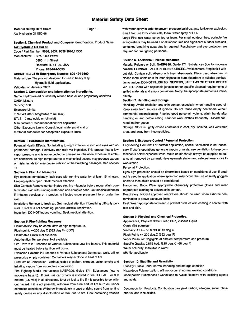
1 QS-2200A ELECTRIC/HYDRAULIC LUBRICATION UNIT OPERATING MANUAL CONTENTS: - PARTS LIST - QS-2200A REQUIREMENTS - LOADING AND OPERATING THE QS-2200A - SEE ITEM 5 FOR SAFETY GAUGE INFORMATION - OPERATING INSTRUCTIONS FOR ELECTRIC HYD. PUMP - PREVENTATIVE MAINTENANCE (Form ) - PARTS LIST AND SCHEMATIC (Form ) - EXTENSION CORD MINIMUM REQUIREMENTS - MATERIAL SAFETY DATA SHEET


2 Val-Tex QS-2200A Electric / Hydraulic Lubrication Gun Delivery: 8 ounces / seconds Weight: 40 Lbs. Lube Sealant Size: J, P, CT12 PSI Rating: 10,000 Overall Dimensions: 20" H X 13" W X 17" L Priming: Self-Priming Electric / Hydraulic Pressure Delivered through a 6 foot hose at 100 PSI: Lube Sealant - 8,000 PSI Valve Flush - 10,000 PSI Gauge: Included Lube Pack Compatible: Yes Internal Relief Valve: Yes NO AIR SOURCE REQUIRED ALLOWS COMPLETE MOBILITY The easy to operate Val-Tex QS-2200A is a fast, compact, rugged lubrication unit. Run by a rechargeable battery powered hydraulic pump, the QS-2200A gives you complete mobility and eliminates the need for an air supply. It is suitable for use with J size lube sealant sticks, Lube Packs, cartridges, and Valve Flush. The unit comes complete with a six foot, 3/8 inch I.D. high pressure hose, 15,000 PSI gauge, Gauge Guard, dual swivels, and a giant buttonhead coupler. The hydraulic pump requires only periodic maintenance and has an internal safety relief valve set at approximately 10,000 PSI to prevent over pressuring the unit. Options available: Unit available with sealant barrel to fit K size lube sealant sticks (Part # QS-2200A-K). Sealant hose lengths up to 10 feet. We do not recommend hoses longer than 10 feet because of the output pressure drop. Part No. Item# Description Qty. QS-2001A Frame 1 PR102 Electric/Hydraulic Pump-12 Volt DC 1 BP212VQ 12 Volt Battery w/ 115 Volt Charger Case 1 QS-2001A- EPLATE Mounting Plate Air Coupler Air Coupler Nipple Grease Hose Assembly 1 Consists of: Lube Pack Adapter 1 6 Giant Buttonhead Coupler 1 1/4 CPLG 1/4"x1/4" Coupling /4"x1/4" Straight Swivel 1.25 TEE 1/4" Tee 1 15MGF 15,000 PSI Gauge 1 GC-250 Gauge Guard Adapter 1/4"x1/ 'x3/8" HP Hose "-27x1/4" Z-Swivel Part No..Item#..Description Qty. 2017A Hydraulic Line Assembly Grease Barrel Assembly.1..Consists of: Grease Barrel Cap R Grease Barrel O-ring Piston Assembly.1.Consists of:.1408-a..5.cap Screw BA.6.Copper Washer Piston Body Snap Ring Retaining Ring Upper and Lower Seal Set Handle.1.25x.375 BSHG..1/4"x3/8" Bushing.1 OPTIONS Shut-Off/Bleeder Valve Gallon Hydraulic Fluid.1 RB12V Replacement Battery.1..Various Hose Lengths FALLSTONE ROAD HOUSTON, TEXAS ORDER PHONE (281) FAX (281) REV. 8/03 16
 supplied, remove sealant barrel cap (1407). 3. Use the handle (1413) to push piston assembly (2008) to the desired depth. When less than full capacity is required, use 1 oz.")

3 QS-2200A Requirements Before Operating the Pump make sure all threaded connections are tight. Loading and Operating the QS-2200A 1. Move the two way positional valve to the "return" position. 2. Using the handle (1413) supplied, remove sealant barrel cap (1407). 3. Use the handle (1413) to push piston assembly (2008) to the desired depth. When less than full capacity is required, use 1 oz. marking on handle. 4. Load Val-Tex lube sealant or Valve Flush as required. Remember to remove cellophane wrapper on sticks. 5. Replace sealant barrel (1407) cap. Tighten with handle (1413) provided. WARNING: FAILURE TO COMPLY WITH THE FOLLOWING SAFETY PROCEDURE COULD RESULT IN SERIOUS INJURY: THE SEALANT CAP MUST BE COMPLETELY SCREWED ONTO THE BARREL BEFORE OPERATING THIS UNIT. THE YELLOW SAFETY GAUGE MUST BE LIFTED UP AND THE BOTTOM SIDE OF THE TAB MUST CLEAR THE TOP OF THE CAP. SAFE STOP 6. Move the two way positional valve to the "hold" position. Then depress the rocker switch to activate the pump. Continue until material flows from end of hose. * Note that the rocker switch requires constant pressure to maintain operation.
4 7. Before removing the coupler from the valve or when the hydraulic pump is not in use, release the pressure on the hydraulic pump. 8. When the cylinder is empty stop the pump. Please refer to step #1. WARNING! If the pump is activated when the sealant barrel cap (1407) is removed, the piston assembly (2008) can be pumped out of the cylinder. * Dispose of any expelled material properly.
5 SPX Corporation 2121 West Bridge Street Owatonna, MN USA Phone: (507) Tech. Services: (800) Fax: (800) Order Entry: (800) Fax: (800) International Sales: (507) Fax: (507) Internet Address: Form No Operating Instructions for: PE102 PE102A PE DC PE DC PE FSC PE PE102-ANCHOR PE102A-220 PE102A-220-FE PE102A-AERO PE102A-COR PE102A-EMP PE102A-ETT PE102AR PE102AR-220 PE104 PE PR102 PR102-AMP P2102-ANCHOR PR102A PR102A-FE PR104 ELECTRIC HYDRAULIC PUMP Max. Capacity: 10,000 PSI NOTE: Inspect the pump upon arrival. Read and carefully follow these instructions. Most problems with new equipment are caused by improper operation or installation. NOTE: These instructions cover several standard pumps. Some special units may appear different or have different specifications. Direct any questions to an appropriate Authorized Hydraulic Service Center or our Technical Services Department. SAFETY PRECAUTION WARNING All WARNING statements must be carefully observed to prevent personal injury. General Operation Before operation the pump, all hose connections must be tightened with proper tools. Do not overtighten. Connections need only be tightened securely and leak-free. Overtightening may cause premature thread failure or may cause high pressure fittings to split at pressures lower than their rated capacities. Should a hydraulic hose ever rupture, burst, or need to be disconnected, immediately shut off the pump and shift the control valve twice to release all pressure. Never attempt to grasp a leaking hose under pressure with your hands. The force of escaping hydraulic fluid could cause serious injury. Do not subject the hose to potential hazard such as fire, extreme heat or cold, sharp surfaces, or heavy impact. Do not allow the hose to kink, twist, curl, or bend so tightly that the oil flow within the hose is blocked or reduced. Periodically inspect the hose for wear because any of these conditions can damage the hose and possibly result in personal injury. Do not use the hose to move attached equipment. Stress may damage the hose and possibly cause personal injury. Hose material and coupler seals must be compatible with the hydraulic fluid used. Hoses also must not come in contact with corrosive materials such as creosote-impregnated objects and some paints. Consult the manufacturer before painting a hose. Never paint the couplers. Hose deterioration due to corrosive materials may result in personal injury. Note: Shaded areas reflect last revision(s) made to this form. Litho in USA Next Page Sheet No. 1 of 3 Rev. 3 Date: 12 Sept. 2000
6 Parts List, Form No , Back sheet 1 of 3 Safety Precautions (Continued) Pump Do not exceed the PSI hydraulic pressure rating noted on the pump name plate or tamper with the internal high pressure relief valve. Creating pressure beyond rated capacities may result in personal injury. Before replenishing the oil level, retract the system to prevent overfilling the pump bladder. An overfill may cause personal injury due to excess bladder pressure created when cylinders are retracted. Cylinder Do not exceed rated capacities of the cylinders. Excess pressure may result in personal injury. Do not set poorly-balanced or off-center loads on a cylinder. The load may tip and cause personal injury. Electrical Supply Do not use an ungrounded (two-prong) extension cord (except for 12 VDC). Avoid conditions which could create an electrical hazard. If the power cord is damaged or wiring exposed, replace or repair immediately. Electric Motor SET-UP AND OPERATION WARNING: To help avoid possible personal injury, Any electrical work must be done by a qualified electrician. Disconnect the power supply before removing the motor casing cover or performing repairs or maintenance. Voltages Motor voltages are not changeable. They are: 12 VDC VDC 120 VAC VAC 50/60 Hz 220 VAC VAC 50/60 Hz Next Page Hydraulic Set-up 1. Clean the areas around the oil ports of the pump and hydraulic cylinders. 2. Inspect the threads and fittings for signs of wear or damage and replace as needed. Clean all hose ends, couplers, and union ends. 3. Remove the thread protectors from the hydraulic outlets. Connect the hose assembly to the valve and couple the hose to the cylinder. 4. Seal all pipe connections with a high quality pipe thread sealant. Teflon tape can be used to seal hydraulic connections provided only one layer of tape is used. Apply the tape carefully, two threads back, to prevent it from being pinched by the coupler and broken off inside the pipe end. Any loose pieces of tape could travel through the system and obstruct the flow of oil or cause jamming of precision-fit parts. Filling the Bladder 1. Thoroughly clean the area around the filler cap with a clean cloth to prevent contamination of the oil by foreign particles. 2. Retract all cylinders. 3. Remove the filler cap and insert a clean funnel with filter. Bladder must be filled to the top of filler. All air must be out of bladder. 4. Replace filler cap. IMPORTANT: Tighten filler cap 1/2-1 turn after o-ring contacts sealing surface. Overtightening can cause pump damage.
7 Operating Instructions Form No Valve Operation 2-Position, 2-Way Manual Valves used with Single-acting Cylinders 1. To build pressure, turn the valve control handle counterclockwise (CCW). 2. Start the pump by pressing the motor control ON/OFF switch. NOTE: Oil advances the cylinder when the unit is activated. 3. When the cylinder has advanced to the desired position, release the motor control ON/OFF switch. 4. To retract the cylinder, turn the valve control clockwise (CW). NOTE: The valve works the same as the manifold if the pump is operated with the valve in the RETURN position. In this position, the cylinder advances when the pump is running and retracts when the motor is stopped. When the valve is in the HOLD position, the cylinder advances when the pump is running and holds when the motor is stopped. The cylinder can be retracted, with the pump off, by moving the valve to the RETURN position. Manifold Assembly used with Single-acting Cylinders or Remote Valves 1. Start the pump by pressing the motor control ON/OFF switch. NOTE: Oil advances the cylinder when the unit is activated. 2. When the cylinder has advanced to the desired position, release the motor control ON/OFF switch. The cylinder will retract. Tandem Center 4-Way Control Valve used with Double-acting Cylinders 1. Place the valve control lever in the NEUTRAL or hold position. 2. Start the pump by pressing the motor control ON/OFF switch. 3. Advance the cylinder by shifting the valve control lever to the ADVANCE position. 4. When the cylinder has advanced to the desired position, release the motor control ON/OFF switch. Cylinder will hold pressure. NOTE: The cylinder momentarily loses pressure during the transition between valve positions. 5. Retract the cylinder by shifting the valve control lever to the RETRACT position and pressing the motor control ON/OFF switch. Cylinder will retract as long as switch is held. Pressure Regulator A pressure regulator can be adjusted to bypass oil at a desired pressure setting while the pump motor continues to run. IMPORTANT: For easy adjustment of the pressure regulator, always adjust the pressure by INCREASING it to a desired pressure setting. The pressure range for these pumps is from 1,000 PSI to 10,000 PSI. 1. Loosen the regulator locking nut, and turn the adjusting knob a few turns counterclockwise (CCW) to decrease the pressure setting to a lower than desired pressure. 2. Connect the pump completely. Place the pump s rocker switch in the ON position. 3. Slowly turn the adjusting knob in a clockwise (CW) direction to gradually increase the pressure setting. When the desired pressure setting is reached, lock the adjusting knob into position by tightening the locking nut. Next Page Sheet No. 2 of 3 Rev. 3 Date: 12 Sept. 2000
8 Operating Instructions, Form No , Back sheet 2 of 3 Pressure Switch A pressure switch can be adjusted to stop the pump motor at a desired pressure setting and restart the motor when the pressure falls below that setting. It is recommended that a pressure switch be used with a pressure regulating valve to insure accuracy when setting a maximum PSI level. A pressure switch alone will break the motor s energy supply at a selected setting, but the hydraulic pump will continue building pressure as it slows to a stop. The pressure regulating valve is adjusted at a setting slightly above the pressure switch setting to compensate by releasing the pressure developed by the hydraulic pump as it coasts to a stop. As a result, the pressure limit requirement can be held to approximately 300 PSI. Adjusting The Pressure Switch Setting 1. Loosen the locknut on the pressure switch. Slowly turn the pressure switch adjusting screw in a counterclockwise (CCW) direction, decreasing the pressure switch setting until the pump motor shuts off. Tighten the locknut to lock the adjusting screw. 2. Release the hydraulic pressure. Run the pump to check the pressure setting and automatic shutoff of the motor. It may be necessary to make a second fine adjustment. PREVENTIVE MAINTENANCE WARNING: To help avoid possible personal injury, Disconnect the pump from the power supply before performing maintenance or repair procedures. Repairs and maintenance should be performed in a dust-free area by a qualified technician. Bleeding Air from the System Air can accumulate in the hydraulic system. This air causes the cylinder to respond in an unstable or slow manner. To remove the air: 1. Position hydraulic cylinder(s) on their sides with the couplers located upward and at a lower level than the pump. 2. Remove any load from the cylinder(s), and cycle the hydraulic system through several cycles (fully extend and retract the cylinders). 3. The bladder must be vented and refilled (see "Filling the Bladder" section on sheet 2 of 3). Hydraulic Fluid Level 1. Check the oil level in the bladder after each 10 hours of use. With all cylinders retracted and the pump in the upright (or vertical) position, the oil level should be at the top of the filler hole. 2. When adding oil, use Power Team approved, high-grade hydraulic oil ( F). Retract the cylinders and disconnect the power supply. Clean the area around the filler plug, remove the plug, and insert a clean funnel with filter. 3. The frequency of oil changes will depend upon the general working conditions, severity of use, and overall cleanliness and care given the pump. Three hundred hours of use under general shop conditions is considered a standard change interval. Drain, flush, and refill the bladder with Power Team approved, high-grade hydraulic oil ( F). Maintenance and Cleaning 1. Keep the pump's outer surface as free from dirt as possible. 2. Seal all unused couplers with thread protectors. 3. Keep all hose connections free of dirt and grime. 4. Equipment connected to the pump must be kept clean. 5. Use only Power Team approved, high-grade hydraulic oil in this pump. Change as recommended (approx. every 300 hours).
9 Operating Instructions Form No ELECTRICAL SCHEMATIC 115/230 V., 50/60 Hz, SINGLE PHASE L1 L2 L3 FU 6.25A M1 REC + M2 MTR H1 H3 H2 H4 T X1 24V X2 CONTROL CIRCUIT SW SW2 REMOTE M Transformer Connections: For 115 VAC H1 & H3 to L1 H2 & H4 to L2 For 230 VAC H1 to L1 H2 to H3 H4 to L2 Sheet No. 3 of 3 Rev. 3 Date: 12 Sept. 2000
10 Operating Instructions, Form No , Back sheet 3 of 3 ELECTRICAL SCHEMATIC 12 VDC (CCW ROTATION FROM LEAD END) OPTIONAL REMOTE M1
11 Form No SPX Corporation 2121 West Bridge Street Owatonna, MN USA Phone: (507) Tech. Services: (800) Fax: (800) Order Entry: (800) Fax: (800) To Parts List International Sales: (507) Fax: (507) Internet Address: Parts List for: MODEL B (Model C for PE102A-GRC) ELECTRIC HYDRAULIC PUMP Max. Capacity: 10,000 PSI 5 PE10 Series PR10 Series 6 For manifold or valve options, see "PARTS INCLUDED BUT NOT SHOWN" section of list See Detail V , , , Basic Pump Assembly See back sheet 2 of SECTION X-X Sheet No. 1 of 6 17 Litho in USA Rev. 6 Date: 19 Jan. 2001
12 Parts List, Form No , Back sheet 1 of 6 Item Part No. Item Part No. No. No. Req'd Description No. No. Req d Description Warning & Fill Instructions Decal 2 * Backup Washer (1/2 X 3/8 X 1/16) 3 * O-ring (1/2 X 3/8 X 1/16; For PE102, PE , PE104, PE , PR102 & PR104) O-ring (1/2 X 3/8 X 1/16; For PE102, PE , PE104, PE , PR102 & PR104) * O-ring (1/2 X 3/8 X 1/16; For PE102A, PE102A-220 & PR102A) O-ring (1/2 X 3/8 X 1/16; For PE102A, PE102A-220 & PR102A) Bushing (For PE102, PE102A, PE , PE102A-220, PR102 & PR104) Bushing (For PE104, PE & PR104) Rocker Switch Cord Set (For PE Series only) Electrical Plug (For PR Series only) ft. Electrical Cable (For PR Series only) Bushing Machine Screw (10-24 UNC X 1 3/4 Lg.) Locknut (10-24 UNC) Base Plate Trade Name Decal (For PR Series) Trade Name Decal (For PE Series) Trade Name Decal (For LUKAS) Screw (#10-24 X 1/2 Lg.; Place ground wire terminal between cover & housing.) Screw (#9-15 X 1" Lg.) ft. Motor Mounting Strap " Channel Rubber "D" Bushing Plug Relay (For PE Series only) Screw (#6-32 X 3/8 Lg.) Transformer (For PE Series only) Relay (For PR Series only) Rectifier (For PE Series only) Screw (6-32 x 3/4 Lg.; For PE Series only) Plastic Housing Plastic Housing (For PE102AR & PE102AR-220) Hex Nut (5/8-18 UNF) Washer (For 5/8 Bolt) Filler Adapter 26 * O-ring (.558 x.414 x.072) O-ring (.558 x.414 x.072) O-ring Boss Plug Retaining Ring Retainer Washer Bladder Bladder Hose Clamp PARTS INCLUDED BUT NOT SHOWN Decal (EPR Seals) Cord Set (For PR Series only) Screw (Torque to 160/180 in. lbs. Tighten the screw on the right hand side facing the pump first.) * O-ring (1/2 X 3/8 X 1/16; For PE102A, PE102A-220, & PR102A) O-ring (1/2 X 3/8 X 1/16; For PE102A, PE102A-220, & PR102A) Remote Switch (For PR102A-DEUT) Remote Switch (For PE102A-EMP) Bushing (For units equipped with a remote switch) Fuse (For PE102, PE102A, & PE104) Fuse (For PE , PE102A-220, & PE ) Receptacle (For PE102AR& PE102AR-220) Screws (#10-24 X 1/2 Lg.; For PE102AR& PE102AR-220) OTHER OPTIONS AND ACCESSORIES Manifold (For PE102A, PE102A-220, PR102A, PE102A-EMP & PR102A-DEUT; See Form No ) Position, 2-Way Valve (For PE102, PE PE102A-EMP, PR102A-DEUT & PR102; See Form No ) Position, 4-Way Valve (For PE104, PE , & PR104; See Form No ) Pressure Regulator (For PE102-ANCHOR; See Form No ) Foot Switch Assembly Hand Switch Assemby Pressure Switch (See Form No ) BP12V 1 12 Volt Battery Pack (Includes sealed lead acid battery, 115 V. charger, battery-to-pump 4 ft. cord set, carrying case and shoulder strap. VC220 1 Voltage Converter w/ Plug Adapters (Converts 220 V. 50/60 cycle to 110 V. 50/60 cycle) RB12V 1 Replacement Battery only RC12V 1 Replacement Battery 4 Ft. Cord Set (For BP12V) Manifold (For PE DC & PE DC) Electrical Plug (For LUKAS) Part numbers marked with an asterisk (*) are contained in Repair Kit No Part numbers marked with a dagger ( ) are contained in EPR Seal Kit No NOTE: For LUKAS brand pumps, if additional parts (that are not shown here) need replacing, contact your nearest LUKAS service center. To Drawing
13 Parts List Form No DETAIL FOR 4-WAY VALVE OUTLET CHECK (FOR PE104, PE , & PR104) Item Part No. No. No. Req'd Description Outlet Ball Stop 2 * Compression Spring (5/32 O.D. X 3/4 Lg.) 3 * Ball (3/16 Dia.) Part numbers marked with an asterisk (*) are contained in Repair Kit No DETAIL V 3 Grd Note: Serrated lockwasher must be adjacent to pump body. Power Cord Ground (Must be isolated between nuts and can be at top or bottom of stack.) 1 2 Item Part No. No. No. Req'd Description Machine Screw (#10-24 UNC X 3/4 Lg.) Nut (#10-24 UNC) Lockwasher (#10 External Tooth) Sheet No. 2 of 6 Rev. 6 Date: 19 Jan. 2001
14 Parts List, Form No , Back sheet 2 of 6 BASIC PUMP ASSEMBLY Item Part No. No. No. Req'd Description Screw (1/4-20 UNC X 3/8 Lg.; Torque to 80/100 in. lbs.) Screw (#10-24 X 2" Lg.; Torque to 60/80 in. lbs.) Screw (#10-24 UNC X 1" Lg.; Torque to 60/80 in. lbs.)
15 Parts List Form No SECTION X-X To Parts List See Detail T Sheet No. 3 of 6 Rev. 6 Date: 19 Jan. 2001
16 Parts List, Form No , Back sheet 3 of 6 Item Part No. No. No. Req'd Description 1 * Compression Spring (3/8 O.D. X 1" Lg.) 2 * Set Screw (#10-24 UNC x 1" Lg. Set unloading valve to 400/500 PSI) 3 * Locknut (10-24 UNC) 4 * Replaceable Seat 5 * O-ring (1/2 X 3/8 X 1/16) O-ring (1/2 X 3/8 X 1/16) 6 * Retaining Ring (Internal) 7 * Filter Motor (For PE102, PE102A, & PE104; For replacement brush assembly, order [2] # ) Motor (For PE , PE102A-220, & PE ; For replacement brush assembly, order [2] # ) Motor (For PR102, PR102A, & PR104; For replacement brush assembly, order [2] # ) Roll Pin 10 * Compression Spring (3/16 O.D. X 5/8 Lg.) 11 * Ball (3/16 Dia.) 12 * O-ring (1/2 X 3/8 X 1/16) O-ring (1/2 X 3/8 X 1/16) 13 * O-ring (3/4 X 5/8 X 1/16) O-ring (3/4 X 5/8 X 1/16) 14 * Copper Washer (15/32 X 5/16 X 1/32) 15 * O-ring (9/16 X 7/16 x 1/16) O-ring (9/16 X 7/16 x 1/16) Plug (1/16 NPTF) Guide Dowel Pin Part numbers marked with an asterisk (*) are contained in Repair Kit No Part numbers marked with a dagger ( ) are contained in EPR Seal Kit No To Drawing 1 2 DETAIL T 3 Item Part No. No. No. Req'd Description Dowel Pin 2 * Backup Washer (15/64 x 1/8 x 3/64) 3 * O-ring (1/4 X 1/8 X 1/16) O-ring (1/4 X 1/8 X 1/16) Part numbers marked with an asterisk (*) are contained in Repair Kit No Part numbers marked with a dagger ( ) are contained in EPR Seal Kit No
17 Parts List Form No SECTION Y-Y To Parts List Sheet No. 4 of 6 Rev. 6 Date: 19 Jan. 2001
18 Parts List, Form No , Back sheet 4 of 6 Item Part No. No. No. Req'd Description 1 * Compression Spring (3/8 O.D. x 1-1/4 Lg.) 3 * Set Screw (#10-24 UNC x 1" Lg.; Set High Pressure Relief Valve to 10,100/10,700 PSI [2,800/3,200 PSI for PE DC & PE DC]) 4 * Locknut (10-24 UNC) 5 * Replaceable Seat 6 * O-ring (1/2 X 3/8 X 1/16) O-ring (1/2 X 3/8 X 1/16) 8 * Steel Ball (1/8 Dia.) 9 * O-ring (3-1/2 X 3-1/4 X 1/8) O-ring (3-1/2 X 3-1/4 X 1/8) 10 * Ball (3/16 Dia.) 11 * Compression Spring (5/32 O.D. X 3/4 Lg.) Ball Guide 13 * Dowel Pin 14 * Compression Spring (1/4 O.D. X 5/8 Lg.) 15 * O-ring (1-1/8 x 15/16 x 1/8) O-ring (1-1/8 x 15/16 x 1/8) Eccentric Automatic Valve Body 18 * Steel Ball (7/32 Dia.) Adapter 20 * Compression Spring (1/4 O.D. X 5/8 Lg.) Spring Retainer Part numbers marked with an asterisk (*) are contained in Repair Kit No Part numbers marked with a dagger ( ) are contained in EPR Seal Kit No To Drawing Refer to any operating instructions included with this product for detailed information about operation, testing, disassembly, reassembly, and preventive maintenance. Items found in this parts list have been carefully tested and selected. Therefore: Use only genuine Power Team replacement parts! Additional questions can be directed to our Technical Services Department.
19 Parts List Form No SECTION Z-Z To Parts List * * * Clean mating surfaces of pump body and end plate (Items #12 & #13). Apply a thin, narrow, continuous band of Loctite gasket eliminator #518 or equivalent, outside of the bolt hole and drain hole patterns on the end plate. End Plate surface that mates with the pump body Thin, narrow continuous band of Loctite #518 or equivalent (permissible within shaded area.) Sheet No. 5 of 6 Rev. 6 Date: 19 Jan. 2001
20 Parts List, Form No , Back sheet 5 of 6 Item Part No. No. No. Req'd Description 1 * Ball (3/16 Dia.) 2 * O-ring (1-7/16 x 1-5/16 x 1/16) O-ring (1-7/16 x 1-5/16 x 1/16) Gerotor Set Dowel Pin Needle Bearing Eccentric Ball Bearing Screw (10-24 UNC x 1-1/4 Lg.; Torque to 60/80 in. lbs.) Retaining Ring (Internal) Washer (25/64 X 3/4 X 1/16) Spring Pin End Plate Pump Body Part numbers marked with an asterisk (*) are contained in Repair Kit No Part numbers marked with a dagger ( ) are contained in EPR Seal Kit No To Drawing 1 MOTOR END VIEW 2 Item Part No. No. No. Req'd Description Screw (10-24 UNC X 1/2 Lg.; Torque to 60/80 in. lbs.) Pin
21 Parts List Form No SECTION S-S Item Part No. No. No. Req'd Description 1 * O-ring (5/16 X 3/16 X 1/16) O-ring (5/16 X 3/16 X 1/16) High Pressure Piston Body 3 * Ball (3/16 Dia.) 4 * Compression Spring (5/32 O.D. X 3/4 Lg.) Dowel Pin Screw (#10-24 UNC X 3/4 Lg.; Torque to 60/80 in. lbs.) High Pressure Cap Body Piston (Position with chamfer towards bearing.) Part numbers marked with an asterisk (*) are contained in Repair Kit No Part numbers marked with a dagger ( ) are contained in EPR Seal Kit No Sheet No. 6 of 6 Rev. 6 Date: 19 Jan. 2001
22 Parts List, Form No , Back sheet 6 of 6 HYDRAULIC SCHEMATIC M HP LP LP S.C. RELIEF VALVE 150 P.S.I. AUTO. VALVE MAX. PRESSURE SAFETY RELIEF VALVE 10,400 P.S.I. OPTIONAL EXT. PRESS. REGULATOR 9,800 P.S.I. TO VALVE LOW PRESSURE UNLOADING VALVE 425 P.S.I. ELECTRICAL INFORMATION Note: All electrical information and schematics for these units can be found in Form No Operating Instructions.
23 Form No SPX Corporation 2121 West Bridge Street Owatonna, MN USA Phone: (507) Tech. Services: (800) Fax: (800) Order Entry: (800) Fax: (800) International Sales: (507) Fax: (507) Internet Address: RECOMMENDED MINIMUM WIRE SIZE-AWG (mm 2 ) OF EXTENSION CORDS FOR POWER TEAM ELECTRIC PUMPS Cord Size AWG (mm 2 ) 3.2 Volt Drop Current Length of Cord At Full Load (Amps) 0-25 feet (0-8 m) feet (8-15 m) feet (15-30 m) feet (30-45 m) 6 18 (.82) 16 (1.33) 14 (2.09) 12 (3.32) 8 18 (.82) 16 (1.33) 12 (3.32) 10 (5.37) (.82) 14 (2.09) 12 (3.32) 10 (5.37) (1.33) 14 (2.09) 10 (5.37) 8 (8.37) (1.33) 12 (3.32) 10 (5.37) 8 (8.37) (1.33) 12 (3.32) 10 (5.37) 8 (8.37) (2.09) 12 (3.32) 8 (8.37) 8 (8.37) (2.09) 12 (3.32) 8 (8.37) 6 (13.30) (2.09) 10 (5.37) 8 (8.37) 6 (13.30) (2.09) 10 (5.37) 8 (8.37) 6 (13.30) (3.32) 10 (5.37) 8. (8.37) 6 (13.30) (3.32) 10 (5.37) 6 (13.30) 4 (21.29) (3.32) 10 (5.37) 6 (13.30) 4 (21.29) Litho in USA Note: Shaded areas reflect last revision(s) made to this form. Sheet No. 1 of 1 Issue Date: Rev
24
25
ELECTRIC HYDRAULIC PUMP Max. Capacity: 10,000 PSI
 Form No. 070 SPX Hydraulic Technologies 5885 th Street Rockford, IL 09-99 USA powerteam.com Tech Services: (800) 477-8 Fax: (800) 75-8 Order Entry: (800) 54-48 Fax: (800) 88-70 Parts List for: PE0 Series
TWO-STAGE HYDRAULIC PUMP. RWP55-IBT-Air
 ORIGINAL INSTRUCTIONS Form No.1000458 5 SPX Corporation 5885 11th Street Rockford, IL 61109-3699 USA Tech. Services: (800) 477-8326 Fax: (800) 765-8326 Order Entry: (800) 541-1418 Fax: (800) 288-7031 Internet
WCI-20 Power-Pak Coldwork Hydraulic Power Supply Rev B
 WCI-20 Power-Pak Coldwork Hydraulic Power Supply Rev B OM-PS-9303-2 Seattle, Washington WCI-20 Power Pak Manual Table of Contents Section 1 Introduction 1.1 Introduction... 1 1.2 Safety Precautions...
ELECTRIC HYDRAULIC PUMP
 Form No. 100825 Parts List for: PE460A-50-220 PE460A-ABC ELECTRIC HYDRAULIC PUMP Motor Control Assembly See pgs. 4 & 5 of 5 Basic Pump Assembly See pg. 2 of 5 Sheet No. 1 of 5 SPX Corporation Rev. 2 Date:
ELECTRIC HYDRAULIC PUMP
 SPX Corporation 5885 11th Street Rockford, IL 61109-3699 USA Internet Address: http://www.powerteam.com Tech. Services: (800) 477-8326 Fax: (800) 765-8326 Order Entry: (800) 541-1418 Fax: (800) 288-7031
Operating instructions Form no safety definitions
 Operating instructions Form no. 1000437 safety definitions safety symbols are used to identify any action or lack of action that can cause personal injury. Your reading and understanding of these safety
MODEL B ELECTRIC HYDRAULIC PUMP
 SPX Corporation 5885 11th Street Rockford, IL 61109-3699 USA Internet Address: http://www.powerteam.com Tech. Services: (800) 477-8326 Fax: (800) 765-8326 Order Entry: (800) 541-1418 Fax: (800) 288-7031
MODEL B ELECTRIC HYDRAULIC PUMP TOP VIEW
 Form No. 0495 SPX Corporation 55 th Street Rockford, IL 09-399 USA Internet Address: http://www.hytec.com Tech. Services: (00) 4-3 Fax: (00) 5-3 Order Entry: (00) 54-4 Fax: (00) -03 Parts List for: 009
ELECTRIC HYDRAULIC PUMP
 Form No. 10198 SPX Corporation 88 11th Street Rockford, IL 61109-3699 USA Internet Address: http://www.hytec.com Tech. Services: (800) 77-8326 Fax: (800) 76-8326 Order Entry: (800) 1-118 Fax: (800) 288-7031
Tech. Services: (800) Fax: (800) Order Entry: (800) Fax: (800)
 Fax: (800) Order Entry: (800) Fax: (800)") SPX Corporation 5885 11th Street Rockford, IL 61109-3699 USA Internet Address: http://www.hytec.com Tech. Services: (800) 477-8326 Fax: (800) 765-8326 Order Entry: (800) 541-1418 Fax: (800) 288-7031 Parts
SPX Corporation 5885 11th Street Rockford, IL 61109-3699 USA Internet Address: http://www.hytec.com Tech. Services: (800) 477-8326 Fax: (800) 765-8326 Order Entry: (800) 541-1418 Fax: (800) 288-7031 Parts
Air / Hydraulic Pump
 Form No. 538016 Parts List & Operating Instructions for: 2510A Original Instructions Air / Hydraulic Pump Maximum Capacity: 690 bar (10,000 psi) Description: The 2510A air/hydraulic pump is designed to
Tech. Services: (800) Fax: (800) Order Entry: (800) Fax: (800) MODEL C ELECTRIC HYDRAULIC PUMP
 Fax: (800) Order Entry: (800) Fax: (800) MODEL C ELECTRIC HYDRAULIC PUMP") SPX Corporation 5885 11th Street Rockford, IL 61109-3699 USA Internet Address: http://www.powerteam.com Tech. Services: (800) 477-8326 Fax: (800) 765-8326 Order Entry: (800) 541-1418 Fax: (800) 288-7031
SPX Corporation 5885 11th Street Rockford, IL 61109-3699 USA Internet Address: http://www.powerteam.com Tech. Services: (800) 477-8326 Fax: (800) 765-8326 Order Entry: (800) 541-1418 Fax: (800) 288-7031
Form No , 3 4, 5 VALVE DETAIL DIVISION UNEX CORPORATION. Parts List for: HYTORC-115 HYTORC-230 HYTORC MODEL D ELECTRIC HYDRAULIC PUMP
 > Parts List for: Form No. 105548 DIVISION UNEX CORPORATION 333 STATE ROUTE 17 NORTH MAHWAH, N.J. 07430-9895 Tel: (201) 512-9500 Fax: (201) 512-0530 HYTORC-115 HYTORC-230 HYTORC-230-2 MODEL D ELECTRIC
Collision Repair Set. Form No No. 1517A 4-Ton Set. No. 1519A 10-Ton Set. Parts List & Operating Instructions for: 1519A. Part No. Item No.
 SPX Corporation 655 Eisenhower Drive Owatonna, MN 55060-0995 USA Phone: (507) 455-7000 Tech. Serv.: (800) 533-6127 Fax: (800) 955-8329 Order Entry: (800) 533-6127 Fax: (800) 283-8665 International Sales:
Tech. Services: (800) Fax: (800) Order Entry: (800) Fax: (800)
 Fax: (800) Order Entry: (800) Fax: (800)") SPX Corporation 5885 11th Street Rockford, IL 61109-3699 USA Internet Address: http://www.powerteam.com Tech. Services: (800) 477-8326 Fax: (800) 765-8326 Order Entry: (800) 541-1418 Fax: (800) 288-7031
SPX Corporation 5885 11th Street Rockford, IL 61109-3699 USA Internet Address: http://www.powerteam.com Tech. Services: (800) 477-8326 Fax: (800) 765-8326 Order Entry: (800) 541-1418 Fax: (800) 288-7031
MODEL B ELECTRIC HYDRAULIC PUMP
 Parts List for: Form No. 05 STATE RTE. 7 NORTH MAHWAH, NJ 070-995 Tel: (0) 5-9500 Fax: (0) 5-95 HYTORCQAS-C5 HYTORCQAS-C0 MODEL B ELECTRIC HYDRAULIC PUMP, 5 9 7 5, Motor Control Assemblies See sheets 5
ELECTRIC HYDRAULIC PUMP
 Parts List for: Form No. 1000048 PE55TWP PE55TWP-220 MODEL D ELECTRIC HYDRAULIC PUMP Maximum Capacity: 10,000 PSI See Back Sheet 5 of 8 1 13 2,3 11 OFF ON WARNING 6 4,5 0IL 7 VALVE DETAIL TORQUE SPOOL
Form No Parts List for: MODEL B ELECTRIC HYDRAULIC PUMP. Maximum Capacity: 10,000 PSI PE55TWP-IBT-115. Sheet No. 1 of 8
 Parts List for: Form No. 1000457 PE55TWP-IBT-115 MODEL B ELECTRIC HYDRAULIC PUMP Maximum Capacity: 10,000 PSI 1 2 3 7 SPX Hydraulic Technologies, Rockford, IL 61109 USA www.powerteam.com Made in USA 309219Rev7
MODEL D ELECTRIC TWO-STAGE HYDRAULIC PUMP
 l e s i MADE IN U.S.A. FOR HYDRAULIC w i t h ANS I B4 0. 1 Parts List for: SPX Hydraulic Technologies 5885 11th Street Rockford, IL 61109-3699 USA powerteam.com Tech Services: +1 800 477 8326 Fax: +1 800
MODEL B HYDRAULIC PUMP
 < < SPX Corporation 5885 11th Street Rockford, IL 61109-3699 USA Internet Address: http://www.powerteam.com Tech. Services: (800) 477-8326 Fax: (800) 765-8326 Order Entry: (800) 541-1418 Fax: (800) 288-7031
Parts List for: Sheet No. 1 of 7. Rev. 19 Date: 4 Nov SPX Hydraulic Technologies. powerteam.com. Model B Units.
 SPX Hydraulic Technologies 5885 11th Street Rockford, IL 61109-3699 USA Tech. Services: (800) 477-8326 Fax: (800) 765-8326 Order Entry: (800) 541-1418 Fax: (800) 288-7031 powerteam.com SPX Corporation
MANUAL PALLET VALVE # Manifold Mount Outlet Port # /16-20 UNF SAE-4 Outlet Port # /4 NPT Outlet Port Max. Capacity: 5,000 PSI
 Form No. 102963 SPX Corporation 5885 11th Street Rockford, IL 61109-3699 USA Internet Address: http://www.hytec.com Tech. Services: (800) 477-8326 Fax: (800) 765-8326 Order Entry: (800) 541-1418 Fax: (800)
MODEL B ELECTRIC HYDRAULIC PUMP
 DIVISION UNEX CORPORATION 333 STATE ROUTE 7 NORTH MAHWAH, N.J. 07430- Tel: (0) -00 Fax: (0) -030 Parts List for: Form No. 0 HYTORCQAS- MODEL B ELECTRIC HYDRAULIC PUMP "A" "A", 4 7 3, 4 Motor Control Assemblies
OPERATOR S MANUAL Model 60010
 OPERATOR S MANUAL Model 60010 10- TON SNAP LOCK PORTA POWER SET W/ WHEELED CASE PROFESSIONAL HYDRAULIC JACKS 1531 W. Mohawk Drive Phone 715-453-9602 Customer Service 800-995-2250 Tomahawk, WI 54487 Fax
VALVE ASSEMBLY. Form No "A" "A" Parts List for: (1/4 N.P.T.F.-REF.) (1/4 N.P.T.F.-REF.)
 (1/4 N.P.T.F.-REF.)") Parts List for: Form No. 108100 SPX Corporation 5885 11th Street Rockford, IL 61109-3699 USA Internet Address: http://www.powerteam.com Tech. Services: (800) 477-8326 Fax: (800) 765-8326 Order Entry: (800)
Parts List for: Form No. 108100 SPX Corporation 5885 11th Street Rockford, IL 61109-3699 USA Internet Address: http://www.powerteam.com Tech. Services: (800) 477-8326 Fax: (800) 765-8326 Order Entry: (800)
Tech. Services: (800) Fax: (800) Order Entry: (800) Fax: (800)
 Fax: (800) Order Entry: (800) Fax: (800)") SPX Corporation 5885 11th Street Rockford, IL 61109-3699 USA Tech. Services: (800) 477-8326 Fax: (800) 765-8326 Order Entry: (800) 541-1418 Fax: (800) 288-7031 Parts List for: Form No. 108184 RSST-20 Internet
SPX Corporation 5885 11th Street Rockford, IL 61109-3699 USA Tech. Services: (800) 477-8326 Fax: (800) 765-8326 Order Entry: (800) 541-1418 Fax: (800) 288-7031 Parts List for: Form No. 108184 RSST-20 Internet
Form No CE Parts List for:
 Form No. 1000048CE Parts List for: PE55TWP-E110 PE55TWP-E220 MODEL B ELECTRIC HYDRAULIC PUMP Maximum Capacity: 10,000 PSI 8 9 TORQUE SPOOL 110-120 IN. LBS. TORQUE NUT 15-20 IN. LBS. 5 3,4 1,2 VALVE DETAIL
HYDRAULIC PUMP. Parts List for: Form No Rev. 20 February, 2016
 S PX Hydraulic Technologies 5885 11th Street Rockford, IL 61109-3699 USA powerteam.com Tech Services: +1 800 477 8326 Fax: +1 800 765 8326 Order Entry: +1 800 541 1418 Fax: +1 800 288 7031 Parts List for:
Tech. Services: (800) Fax: (800) Order Entry: (800) Fax: (800) MODEL F AIR HYDRAULIC PUMP
 Fax: (800) Order Entry: (800) Fax: (800) MODEL F AIR HYDRAULIC PUMP") Form No. 08 SPX Corporation 88 th Street Rockford, IL 09-99 USA Internet Address: http://www.hytec.com Tech. Services: (800) 477-8 Fax: (800) 7-8 Order Entry: (800) 4-48 Fax: (800) 88-70 Parts List for:
Form No. 08 SPX Corporation 88 th Street Rockford, IL 09-99 USA Internet Address: http://www.hytec.com Tech. Services: (800) 477-8 Fax: (800) 7-8 Order Entry: (800) 4-48 Fax: (800) 88-70 Parts List for:
AIR HYDRAULIC PUMP SIDE VIEW
 Parts List for: form No. 101260 PA462 PA464 PA464-5R AIR HYDRAULIC PUMP SIDE VIEW 7 Basic Pump Ass'y See sheet 2 of 4. 1 6 5 2 4 Item Part No. Item Part No. No. No. Req d Description No. No. Req d Description
Air / Hydraulic Pump Instructions. CAUTION: Read and Understand These Operating, Servicing, and Safety Instructions, Before Using This Machine.
 Air / Hydraulic Pump Instructions CAUTION: Read and Understand These Operating, Servicing, and Safety Instructions, Before Using This Machine. 1-800-467-2464 10 Cooperative Way Wright City, MO 63390 P.O.
Operating Instructions for: PE10 Series. Electric-Powered 10 Series Hydraulic Pump SPX
 Operating Instructions for: PE10 Series Electric-Powered 10 Series Hydraulic Pump Table of Contents Description............................................................2 PE10-Series Electric / Hydraulic
Operating, Servicing, and Safety Manual Model # Hydraulic Bender
 Operating, Servicing, and Safety Manual Model # 900 90 Hydraulic Bender CAUTION: Read and Understand These Operating, Servicing, and Safety Instructions, Before Using This Machine. 1-800-467-2464 10 Cooperative
Form No , 9 5, 6. Parts List for: X1A1 AIR DRIVEN WITH REMOTE CONTROL HYDRAULIC PUMP. Max. Capacity: 10,000 PSI
 Form No. 101249 Parts List for: X1A1 AIR DRIVEN WITH REMOTE CONTROL HYDRAULIC PUMP Max. Capacity: 10,000 PSI Air Motor Assembly See sheet 3 of 6 13 12 1 11 10 8, 9 Basic Pump Assembly See sheet 4 of 6
Form No , 3, 4. Parts List for: MODEL F AIR HYDRAULIC PUMP. Maximum Capacity: 10,000 PSI. Item Part No. No. No.
 SPX Corporation Eisenhower Drive Owatonna, MN 00-099 USA Phone: (0) -000 Tech. Services: (800) 33- Fax: (800) 9-839 Order Entry: (800) 33- Fax: (800) 83-8 International Sales: (0) -90 Fax: (0) -03 Parts
Form No , 3, 4 5. Parts List for: MODEL F AIR HYDRAULIC PUMP. Maximum Capacity: 10,000 PSI. Item Part No. No. No.
 SPX Corporation Eisenhower Drive Owatonna, MN 00-099 USA Phone: (0) 4-000 Tech. Services: (00) 33-2 Fax: (00) 9-329 Order Entry: (00) 33-2 Fax: (00) 23- International Sales: (0) 4-290 Fax: (0) 4-03 Parts
Shop Press. Maximum Capacity: 25 Tons and 55 Tons SAFETY PRECAUTIONS
 Operating Instructions for: Form No. 102481 1826 1845 1846A 1847 1872 1872-220v 211200 576780 60361 61275 D01008AA D01009AA WARNING: To prevent personal injury; Shop Press Maximum Capacity: 25 Tons and
Air / Hydraulic Floor Service Jack
 SPX Corporation 655 Eisenhower Drive Owatonna, MN 55060-0995 USA Phone: (507) 455-7000 Tech. Serv.: (800) 533-6127 Fax: (800) 955-8329 Order Entry: (800) 533-6127 Fax: (800) 283-8665 International Sales:
AIR/HYDRAULIC INJECTION GUN MODEL INSTRUCTIONS
 I. OPERATION & DESCRIPTION The Air / Hydraulic Injection Gun is a high-pressure tool that should be used with caution and according to these instructions. IMPORTANT: The Gun is 0,000 psi rated. Do not
IN-LINE HYDRAULIC FLOW TESTER
 SPX Corporation 5885 11th Street Rockford, IL 61109-3699 USA Internet Address: http://www.powerteam.com Tech. Services: (800) 477-8326 Fax: (800) 765-8326 Order Entry: (800) 541-1418 Fax: (800) 288-7031
Under Axle Jack Max. Capacity: 25 Tons
 SPX Corporation 655 Eisenhower Drive Owatonna, MN 55060-0995 USA Phone: (507) 455-7000 Tech. Serv.: (800) 533-6127 Fax: (800) 955-8329 Order Entry: (800) 533-6127 Fax: (800) 283-8665 International Sales:
XP-115 Multi-Port Power Pack Operation and Maintenance Manual
 XP-115 Multi-Port Power Pack Operation and Maintenance Manual http://www.torsionx.com Safety Guide To use the XP-115 Multi-Port Power Pack safely you must follow correct operation guidelines and inspect
Rear Suspension Bushing Remover/Installer
 655 EISENHOWER DRIVE OWATONNA, MN 55060-0995 USA PHONE: (507) 455-7000 TECH. SERV.: (800) 533-6127 FAX: (800) 955-8329 ORDER ENTRY: (800) 533-6127 FAX: (800) 283-8665 INTERNATIONAL SALES: (507) 455-7223
Hydraulic Hub Grappler Kit
 655 EISENHOWER DRIVE OWATONNA, MN 55060-0995 USA PHONE: (507) 455-7000 TECH. SERV.: (800) 533-6127 FAX: (800) 955-8329 ORDER ENTRY: (800) 533-6127 FAX: (800) 283-8665 INTERNATIONAL SALES: (507) 455-7223
KLW4000D Multi-Port Power Pack
 KLW4000D Multi-Port Power Pack Operation and Maintenance Manual Safety Guide To use the KLW4000DMulti-Port Power Pack safely you must follow correct operation guidelines and inspect the equipment regularly.
ELECTRIC HYDRAULIC PUMP
 Parts List for: Form No. 03 SPX Corporation 88 th Street Rockford, IL 09-399 US Internet ddress: http://www.powerteam.com Tech. Services: (800) 4-83 Fax: (800) -83 Order Entry: (800) 4-48 Fax: (800) 88-03
Explanation of Safety Signal Words
 Explanation of Safety Signal Words The safety signal word designates the degree or level of hazard seriousness. DANGER: Indicates an imminently hazardous situation which, if not avoided, will result in
PE39 Series Compact Torque Wrench Pump
 SPX Bolting Systems Unit 4, Wansbeck Business Park Rotary Parkway Ashington Northumberland NE63 8QW spxboltingsystems.com Tel: +44 (0) 1670 850580 Fax: +44 (0) 1670 850655 Operating Instructions for: PE39PED1BPR
MODEL 25-OM-10-C & 25-OA-10-C HYDRAULIC BOOSTER
 SPX Corporation 5885 11th Street Rockford, IL 61109-3699 USA Internet Address: http://www.powerteam.com Tech. Services: (800) 477-8326 Fax: (800) 765-8326 Order Entry: (800) 541-1418 Fax: (800) 288-7031
User Manual for: PE8 Series PE17 Series. Electric-Powered 8 & 17 Series Two-Stage Hydraulic Pump SPX
 User Manual for: PE8 Series PE17 Series Electric-Powered 8 & 17 Series Two-Stage Hydraulic Pump Table of Contents Description............................................................2 PE8/17-Series
User Manual for: PE30 Series. Electric-Powered 30 Series Hydraulic Pump SPX
 User Manual for: PE30 Series Electric-Powered 30 Series Hydraulic Pump Table of Contents Description............................................................2 PE30-Series Electric / Hydraulic Pumps.....................................
User Manual for: PE8 Series PE17 Series. Electric-Powered 8 & 17 Series Two-Stage Hydraulic Pump SPX
 User Manual for: PE8 Series PE17 Series Electric-Powered 8 & 17 Series Two-Stage Hydraulic Pump SPX Form No. 1000559 Rev. 0 February 3, 2012 SPX Form No. 1000559 Rev. 0 February 3, 2012 Table of Contents
Form No Parts List for: RWP55 RWP55-4 MODEL C HYDRAULIC PUMP AIR DRIVEN WITH REMOTE CONTROL GENERAL ASS'Y SIDE VIEW SECTION A-A
 Parts List for: Form No. 000339 RWP55 RWP55-4 MODEL C HYDRAULIC PUMP AIR DRIVEN WITH REMOTE CONTROL GENERAL ASS'Y SIDE VIEW 3 9, 0 4 5 6 6 5 4, 3 9,0 SPX Hydraulic Technologies, Rockford, IL 609 USA powerteam.com
Instruction Manual. 08 Series Auto 2 Speed Electric Power Units Model PEM8414 & PEM8424. Maximum Operating Pressure 700 bar
 08 Series Auto 2 Speed Electric Power Units Model PEM8414 & PEM8424 PEM8414 PEM8424 Maximum Operating Pressure 700 bar ABSOLUTE EQUIPMENT PTY LTD 2/186 Granite Street, GEEBUNG QLD 4034 Australia sales@absoluteequipment.com.au
High Lift Transmission Jack
 SPX Corporation 655 Eisenhower Drive Owatonna, MN 55060-0995 USA Phone: (507) 455-7000 Tech. Serv.: (800) 533-6127 Fax: (800) 955-8329 Order Entry: (507) 455-1480 Fax: (800) 283-8665 International Sales:
XP-AIR Multi-Port Power Pack Operation and Maintenance Manual
 XP-AIR Multi-Port Power Pack Operation and Maintenance Manual http://www.torsionx.com Safety Guide To use the XP-AIR Multi-Port Power Pack safely you must follow correct operation guidelines and inspect
High Lift Transmission Jack
 655 Eisenhower Drive Owatonna, MN 55060 USA Phone: (507) 455-7000 Tech. Serv.: (800) 533-6127 Fax: (800) 955-8329 Order Entry: (800) 533-6127 Fax: (800) 283-8665 International Sales: (507) 455-7223 Fax:
PRODUCT INDEX FALLSTONE ROAD HOUSTON, TEXAS ORDER PHONE (281) FAX (281) REV.
 FAX (281) REV.") PRODUCT INDEX PAGE Our Commitment To You... 1 Lube Sealant Packaging... 2 Lube Sealants and Lubricants... 3-4 Valve Flush... 5 Stem and Thread Compounds... 5 Lubrication Fittings, Adapters, and Tools...
PRODUCT INDEX PAGE Our Commitment To You... 1 Lube Sealant Packaging... 2 Lube Sealants and Lubricants... 3-4 Valve Flush... 5 Stem and Thread Compounds... 5 Lubrication Fittings, Adapters, and Tools...
Instruction Manual. Maximum Operating Pressure 510 bar
 Single Speed Diesel Power Unit Model HPD11 Maximum Operating Pressure 510 bar ABSOLUTE EQUIPMENT PTY LTD 2/186 Granite Street, GEEBUNG QLD 4034 Australia sales@absoluteequipment.com.au Phone: +61 7 3865
Electric-Powered PE8 Series Hydraulic Pump
 Operating Instructions for: PE8LXX3L PE8PXX3L SPX Bolting Systems Unit 4, Wansbeck Business Park Rotary Parkway Ashington Northumberland NE63 8QW Tel: +44 (0) 1670 850580 Fax: +44 (0) 1670 850655 spxboltingsystems.com
International Sales: (507) Fax: (507) Internet Address:
 Fax: (507) Internet Address:") SPX SPX Corporation 2121 West Bridge Street Owatonna, MN 55060 USA Phone: (507) 455-7100 Tech. Services: (800) 477-8326 Fax: (800) 765-8326 Order Entry: (800) 541-1418 Fax: (800) 288-7031 POWER TEAM International
SPX SPX Corporation 2121 West Bridge Street Owatonna, MN 55060 USA Phone: (507) 455-7100 Tech. Services: (800) 477-8326 Fax: (800) 765-8326 Order Entry: (800) 541-1418 Fax: (800) 288-7031 POWER TEAM International
MODEL F AIR HYDRAULIC PUMP
 Parts List for: Form No. 0875 SPX Corporation 5885 th Street Rockford, IL 609-699 USA Internet Address: http://www.powerteam.com Tech. Services: (800) 77-86 Fax: (800) 765-86 Order Entry: (800) 5-8 Fax:
Operating, Servicing, and Safety Manual Model # Hydraulic Bender
 - 1 - Operating, Servicing, and Safety Manual Model # 2500 180 Hydraulic Bender CAUTION: Read and Understand These Operating, Servicing, and Safety Instructions, Before Using This Machine. 1-800-467-2464
Racing Jack Max. Capacity: 3,000 lbs. (1,361 kg)
") R SPX Corporation 655 Eisenhower Drive Owatonna, MN 55060-0995 USA Phone: (507) 455-7000 Tech. Serv.: (800) 533-6127 Fax: (800) 955-8329 Order Entry: (800) 533-6127 Fax: (800) 283-8665 International Sales:
R SPX Corporation 655 Eisenhower Drive Owatonna, MN 55060-0995 USA Phone: (507) 455-7000 Tech. Serv.: (800) 533-6127 Fax: (800) 955-8329 Order Entry: (800) 533-6127 Fax: (800) 283-8665 International Sales:
OPERATIONSMANUAL SUPERIOR BOLTING SOLUTIONS
 OPERATIONSMANUAL SUPERIOR BOLTING SOLUTIONS P L S S E I S E ER H C Q R O T N E R UE W SUPERIOR BOLTING SOLUTIONS SUPERIOR BOLTING SOLUTIONS Contents Chapter 1: General Information 3 1.1 Inspection 3 1.2
IN-LINE HYDRAULIC FLOW TESTER
 SPX Corporation 5885 11th Street Rockford, IL 61109-3699 USA Internet Address: http://www.powerteam.com Tech. Services: (800) 477-8326 Fax: (800) 765-8326 Order Entry: (800) 541-1418 Fax: (800) 288-7031
Tech. Services: (800) Fax: (800) Order Entry: (800) Fax: (800)
 Fax: (800) Order Entry: (800) Fax: (800)") Parts List for: Form No. 068 SPX Corporation 88 th Street Rockford, IL 609-699 USA Internet Address: http://www.powerteam.com Tech. Services: (800) 77-826 Fax: (800) 76-826 Order Entry: (800) -8 Fax: (800)
Parts List for: Form No. 068 SPX Corporation 88 th Street Rockford, IL 609-699 USA Internet Address: http://www.powerteam.com Tech. Services: (800) 77-826 Fax: (800) 76-826 Order Entry: (800) -8 Fax: (800)
IN-LINE HYDRAULIC FLOW TESTER 75 GPM, 300 I/min.
 SPX Corporation 5885 11th Street Rockford, IL 61109-3699 USA Internet Address: http://www.powerteam.com Tech. Services: (800) 477-8326 Fax: (800) 765-8326 Order Entry: (800) 541-1418 Fax: (800) 288-7031
HYDRAULIC PUMP BATTERY POWERED. Operating Instructions for: SPX Hydraulic Technologies th Street Rockford, IL USA powerteam.
 Operating Instructions for: SPX Hydraulic Technologies 5885 11th Street Rockford, IL 61109-3699 USA powerteam.com Tech Services: (800) 477-8326 Fax: (800) 765-8326 Order Entry: (800) 541-1418 Fax: (800)
MODEL B FLANGE SPREADER. Max. Pressure: 10,000 PSI (700 BAR) Unit Weight: 18 LBS. (8.16 Kg)
 Unit Weight: 18 LBS. (8.16 Kg)") Parts List and Operating Instructions for: Form No. 102871 HFS6A MODEL B FLANGE SPREADER Max. Pressure: 10,000 PSI (700 BAR) Unit Weight: 18 LBS. (8.16 Kg) Definition: To break loose or spread pipe flange
Parts List and Operating Instructions for: Form No. 102871 HFS6A MODEL B FLANGE SPREADER Max. Pressure: 10,000 PSI (700 BAR) Unit Weight: 18 LBS. (8.16 Kg) Definition: To break loose or spread pipe flange
Form No Parts List for: MODEL B HYDRAULIC PUMP GENERAL SECTION PG PG553-2UK FT600 PG554. PG120A Series Y70G Series. Sheet No.
 MODEL B HYDRAULIC PUMP GENERAL SECTION Parts List for: Form No. 100520 60208 PG553 65820 PG553-2UK FT600 PG554 FT700-001 PG554-LEAD FT700-002 PG554-2UK PG55A Series Y26G Series PG90A Series Y60G Series
Hydraulic Knockout Sets
 HKO-186 HKO-1810 Hydraulic Knockout Sets OPERATOR S MANUAL! Read this Operator s Manual carefully before using this tool. Failure to understand and follow the contents of this manual may result in serious
Air / Hydraulic Floor Service Jack
 655 Eisenhower Drive Owatonna, MN 55060 USA Phone: (507) 455-7000 Tech. Serv.: (800) 533-6127 Fax: (800) 955-8329 Order Entry: (800) 533-6127 Fax: (800) 283-8665 International Sales: (507) 455-7223 Fax:
IN-LINE HYDRAULIC FLOW TESTER 75 GPM, 300 I/min.
 SPX Corporation 5885 11th Street Rockford, IL 61109-3699 USA Internet Address: http://www.powerteam.com Tech. Services: (800) 477-8326 Fax: (800) 765-8326 Order Entry: (800) 541-1418 Fax: (800) 288-7031
PE 20 SERIES ELECTRIC POWER PUMPS
 A Division Of Templeton, Kenly & Co., Inc. PE 20 SERIES ELECTRIC POWER PUMPS Operating Instructions Manual For 1/2 hp, 115 Volt and 230 Volt PEM, PPM, PES and PPS Models Revison B 07/2006 2525 Gardner
Heavy Duty Electric Hydraulic Pumps PN and
 ORIGINAL INSTRUCTIONS Heavy Duty Electric Hydraulic Pumps PN 69120-1 and 69120-2 Customer Manual 409-1950 27 SEP 16 Rev F SAFETY PRECAUTIONS AVOID INJURY READ THIS FIRST!... 2 1. INTRODUCTION... 3 2. DESCRIPTION...
Arctic Equipment Manufacturing Corporation R04 M673F Power Unit Kit Installation Instructions. M673F installation instructions
 Arctic Equipment Manufacturing Corporation R04 M673F Power Unit Kit Installation Instructions M673F installation instructions Arctic Equipment Manufacturing Corporation R04 M673F Power Unit Kit Installation
FTMP-8 AND FTMP-12 Midget Puller Units
 401 Andover Park East Seattle, Washington 98188-7605 USA (206) 246-2010 FTI OPERATIONS, MAINTENANCE AND REPAIR MANUAL FTMP-8 AND FTMP-12 Midget Puller Units FTI Part #2720-021 Revision A November 18, 2011
Air Assist Bottle Jack Max. Capacity: 12 Tons (4313C) & 20 Tons (4321C) Operating Range: psi
 & 20 Tons (4321C) Operating Range: psi") R SPX Division 655 Eisenhower Drive Owatonna MN 55060 Phone: (507) 455-7000 Tech. Serv.: (800) 533-6127 Fax: (800) 955-8329 Order Entry: (800) 533-6127 Fax: (800) 283-8665 International Sales: (507) 455-7223
R SPX Division 655 Eisenhower Drive Owatonna MN 55060 Phone: (507) 455-7000 Tech. Serv.: (800) 533-6127 Fax: (800) 955-8329 Order Entry: (800) 533-6127 Fax: (800) 283-8665 International Sales: (507) 455-7223
Instruction Manual. Single Acting Hydraulic Aluminium Pull Cylinders RAP Series. Maximum Operating Pressure 700 bar
 Single Acting Hydraulic Aluminium Pull Cylinders RAP Series Maximum Operating Pressure 700 bar ABSOLUTE EQUIPMENT PTY LTD 2/186 Granite Street, GEEBUNG QLD 4034 Australia sales@absoluteequipment.com.au
Instruction Manual. Single Acting, Pancake, Locking Collar Hydraulic Cylinders RPLC Series. Maximum Operating Pressure 700 bar
 Single Acting, Pancake, Locking Collar Hydraulic Cylinders RPLC Series Maximum Operating Pressure 700 bar ABSOLUTE EQUIPMENT PTY LTD 2/186 Granite Street, GEEBUNG QLD 4034 Australia sales@absoluteequipment.com.au
MODEL 890 / 892 POWER POST 10 TON CAPACITY
 MODEL 890 / 892 POWER POST 10 TON CAPACITY Jackco Transnational Inc. LIMITED ONE YEAR WARRANTY Jackco Transnational Inc. warrants all Jackco equipment and tools to the original purchaser against any manufacturing
Air-Assist Service Jack Max. Capacity: 10 Tons
 Form No. 565786 Parts List & Operating Instructions for: 1511B Air-Assist Service Jack Max. Capacity: 10 Tons 109 67 66 68 77 69 70 78 95 94 107 106 108 26 71 72 72 93 X L 65 75 92 91 90 89 88 87 86 85
PED SERIES HYDRAULIC & MECHANICAL POWER ELECTRIC DUMP PUMPS. Operating & Maintenance Instructions Electric Dump Pumps.
 PED SERIES HYDRAULIC & MECHANICAL POWER ELECTRIC DUMP PUMPS SERVING INDUSTRY WITH PRIDE SINCE - Templeton Kenly& Co., Inc. QUALITY Operating & Maintenance Instructions Electric Dump Pumps. EQUIPMENT SERVICE
DETAIL "D" Parts List for: PA9 Series PA9-35 PA9H MODEL B AIR/HYDRAULIC PUMP (TUBE STYLE) FOOT PEDAL STYLE SHOWN 22, 23. 9; See Detail "C" 7, 8 5 6
 FOOT PEDAL STYLE SHOWN 22, 23. 9; See Detail C 7, 8 5 6") Parts List for: SPX Hydraulic Technologies 5885 th Street Rockford, IL 609-699 USA powerteam.com Tech Services: + 800 77 86 Fax: + 800 765 86 Order Entry: + 800 5 8 Fax: + 800 88 70 PA9 Series PA9-5 PA9H
Parts List for: SPX Hydraulic Technologies 5885 th Street Rockford, IL 609-699 USA powerteam.com Tech Services: + 800 77 86 Fax: + 800 765 86 Order Entry: + 800 5 8 Fax: + 800 88 70 PA9 Series PA9-5 PA9H
Instruction Sheet 1 1/8 HP TITAN PUMPS SAFETY FIRST
 Instruction Sheet 1 1/8 HP TITAN PUMPS L1824 Rev. D 06/04 1.0 IMPORTANT RECEIVING INSTRUCTIONS Visually inspect all components for shipping damage. Shipping damage is not covered by warranty. If shipping
Instruction Manual. Maximum Operating Pressure 700 bar
 Remote Hydraulic Cutter Model HC-120R Maximum Operating Pressure 700 bar ABSOLUTE EQUIPMENT PTY LTD 2/186 Granite Street, GEEBUNG QLD 4034 Australia sales@absoluteequipment.com.au Phone: +61 7 3865 4006
P AM & PGM SERIES. 1.5 H.P. Air Pumps. 3.5 and 8 H.P. Gas Pumps AIR & GASOLINE POWER PUMPS HYDRAULIC & MECHANICAL POWER SIMPLEX
 SERVING P AM & PGM SERIES INDUSTRY WITH PRIDE SINCE - Templeton Kenly & HYDRAULIC & MECHANICAL POWER 0 PRO & 0 - MAG SERIES AIR & GASOLINE POWER PUMPS Co., Inc. QUALITY Operating & Maintenance Instructions
Instruction Manual. Double Acting Hydraulic, Hollow Piston Cylinders RHD Series. Maximum Operating Pressure 700 bar
 Double Acting Hydraulic, Hollow Piston Cylinders RHD Series Maximum Operating Pressure 700 bar ABSOLUTE EQUIPMENT PTY LTD 2/186 Granite Street, GEEBUNG QLD 4034 Australia sales@absoluteequipment.com.au
Portable Two-Stage Under Axle Jack Max. Capacity: First Stage: 27.5 Tons Second Stage: 11 Tons. Safety Precautions
 SPX Corporation Eisenhower Drive Owatonna, MN 00-0 USA Phone: (07) -7000 Tech. Serv.: (00) -7 Fax: (00) - Order Entry: (00) -7 Fax: (00) - International Sales: (07) -7 Fax: (07) -70 Form No. Parts List
VALVE AND PLUMBING KIT INSTRUCTIONS SMC 84Q & 2408 LOADERS NEW HOLLAND TRACTORS MODEL 2WD 4WD LESS CAB WITH CAB 1720 X X X 1920 X X X
 ASSEMBLY MANUAL Keep With Operator s Manual VALVE AND PLUMBING KIT INSTRUCTIONS SMC 84Q & 2408 LOADERS NEW HOLLAND TRACTORS MODEL 2WD 4WD LESS CAB WITH CAB 1720 X X X 1920 X X X TRACTOR AND VALVE KIT GENERAL
MODEL MC1500 Installation and Operation Manual Important:
 MODEL MC1500 Installation and Operation Manual Important: This manual contains specific cautionary statements relative to worker safety. Read this manual thoroughly and follow as directed. It is impossible
Service Jack. Form No Parts List & Operating Instructions 1510B. Max. Capacity: 5 and 10 Tons. 1 of 3. Sheet No. Issue Date: Rev.
 SPX Corporation 655 Eisenhower Drive Owatonna, MN 55060-0995 USA Phone: (507) 455-7000 Tech. Serv.: (800) 533-6127 Fax: (800) 955-8329 Order Entry: (800) 533-6127 Fax: (800) 283-8665 International Sales:
Operating Instructions for: PE18 Series. Electric-Powered 18 Series Hydraulic Pump SPX
 Operating Instructions for: E18 Series Electric-owered 18 Series Hydraulic ump able of Contents Description............................................................2 E18-Series Electric / Hydraulic
OPERATION AND MAINTENANCE MANUAL
 WREN IBT SERIES HYDRAULIC TORQUE WRENCHES IBT SQUARE DRIVE SERIES OPERATION AND MAINTENANCE MANUAL FOR WREN Products: POINT 75, 1IBT, 3IBT, 5IBT, 8IBT, 10IBT, 20IBT, 25IBT, 35IBT, 50IBT SQUARE DRIVE HYDRAULIC
AIR CLEANERS Model MC 3000 OWNER S MANUAL CAUTION Read complete instructions before operating. Please file for future reference.
 AIR CLEANERS Model MC 3000 OWNER S MANUAL CAUTION Read complete instructions before operating. Please file for future reference. MODEL MC 3000 SPECIFICATION Input Volts: 208-230/430 VAC, 60Hz, 3 Phase
Tech. Services: (800) Fax: (800) Order Entry: (800) Fax: (800) Internet Address:
 Fax: (800) Order Entry: (800) Fax: (800) Internet Address:") ORIGINAL INSTRUCTIONS Form No.102481 5 SPX Corporatiion 5885 11th Street Rockford, IL 61109-3699 USA Tech. Services: (800) 477-8326 Fax: (800) 765-8326 Order Entry: (800) 541-1418 Fax: (800) 288-7031 Internet
ORIGINAL INSTRUCTIONS Form No.102481 5 SPX Corporatiion 5885 11th Street Rockford, IL 61109-3699 USA Tech. Services: (800) 477-8326 Fax: (800) 765-8326 Order Entry: (800) 541-1418 Fax: (800) 288-7031 Internet
 Operation and Maintenance Manual http://www.torsionx.eu Use the MaxDrv Series Square Drive Torque Wrench Model.75, 1, 3, 5, 8, 10, 20, 25, 35, 50 to install and remove threaded fasteners requiring precise
Instruction Sheet. 1/2 HP Portable Electric Pumps SAFETY FIRST. L2062 Rev. F 02/ IMPORTANT RECEIVING INSTRUCTIONS 2.
 Instruction Sheet 1/2 HP Portable Electric Pumps L2062 Rev. F 02/12 Index: English:...................................... 1-7 Français:.................................... 8-14 Deutsch:...................................
Low Lift Transmission Jack
 655 Eisenhower Drive Owatonna, MN 55060 USA Phone: (507) 455-7000 Tech. Serv.: (800) 533-6127 Fax: (800) 955-8329 Order Entry: (800) 533-6127 Fax: (800) 283-8665 International Sales: (507) 455-7223 Fax: