Impala SS and Caprice T56 Six Speed install guide
|
|
|
- Godfrey Henderson
- 6 years ago
- Views:
Transcription


1 Impala SS and Caprice T56 Six Speed install guide Created by: Mike Fetcko 1
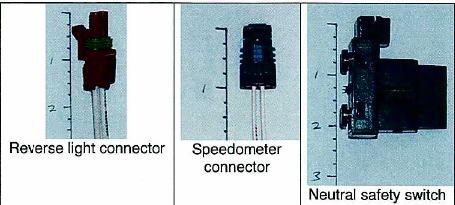
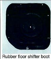
2 Intro First let me tell you a little about myself. My name is Mike Fetcko and I live currently in Kalamazoo, Michigan. I am an Avionics Systems Engineer and work for a company that modifies business class jets. I got bitten by the B-Body bug a couple of years back when helping out my best friend with his 1996 Impala SS. Started digging into the car and before you knew it I was pretty fluent on the inner working, from suspension, engine, tranny, etc. I purchased my first 9C1 in 2007 for a whole 750 bucks. It is a 1994 model, which was pretty basic. Well it has undergone quite a few transformations since then. Paint, bodywork, T56 installation, engine mods (typical bolt on s), suspension upgrade and all that jazz. This past fall I purchased another C1 for a whole 250 bucks from Ebay, has about 182,000 miles on it now and runs like a champ. This is the quintessential winter beater, but it actually has a better body on it than my other 9C1 had on it, before bodywork. Well on with the guide. I want to document all that I have learned while doing this installation on my car and all that I have learned from Impalassforum.com members along the way. I am not saying this is going to be the perfect guide but it will get you on track with what you need to do this installation yourself. Torque specifications will be listed on page 35 for reference and also pictures of some of the parts that you are going to need so that you have a visual reference. 2
3 Here we go First you are going to need to locate the transmission. When looking for a transmission you are going to find that they are going to run from as cheap as 1,000 to as expensive as 3,600, where the last number being for a unit that has all upgraded internals and a viper tail shaft. It all depends on whether you can get a great deal on a used transmission, that doesn t need to be rebuilt or a brand new unit from D&D or any other supplier out there. You can use a F-Body T56. The 1993 unit has a lower front side gear and a.62 overdrive ratio in 6 th gear, but the torque rating is down to 400 ft-lbs units are rated at 450 ft-lbs or torque and the 6 th gear ratio is.50. This is the transmission that most go with. Here is a list of details on these units Trans/source 1 st 2 nd 3 rd 4 th 5 th 6 th Max torque 1993 LT1 F-body T lb-ft w/2.73's LT1 F-body lb-ft T56 LT1 F-body T56 w/3.23's (G92) lb-ft Trans/source GM part number Tremec part number 1993 LT1 F-body T56 w/2.73's or LT1 F-body T or LT1 F-body T56 w/3.23's (G92) or Once your transmission is located and if you get a used unit work out a deal to get all these items listed below or if buying new you will have to search heavily to find the parts that you need. I would recommend searching the Camaro and Firebird discussion boards for parts as they come up there often: 1. bellhousing with bolts 2. flywheel with bolts 3. the hydraulics for the clutch, including master and slave unit 4. Inspection plate (these are hard to find, I have a way out of this if you can t find one.) 5. Shifter, if you plan on using the original. If not this is not needed. 6. F-Body pedal assembly with all the clutch switches and brake switches 7. Tunnel shift boot 8. And all the switches and connectors from the transmission including: reverse lockout, Vss connector (if you have a 94 or 95 car, if you have a 96 the original connector will plug right in.) and Reverse lights. This should be all that you need from an F-body donor car to start your B-bodies transformation. 3


4 Now listed below are the items that you are going to have to purchase to install the T56 into your B-Body. 1. T56 Crossmember, available from Clearimageautomotive.com Or you can modify you existing unit. Modifying the existing unit is going to take time, patience and welding skills to accomplish this. Dan s crossmember is roughly $ and it comes with the tranny mount. The next picture gives you an idea of the surgery that you will have to do to the original to make it work. Essentially you will have to drop the original mounting point on the cross member, by roughly 1.5 inches. 4

5 2. The F2B clutch pedal bracket kit. This kit is only available through Tony on Ebay. Contact seller Scoobydoo321 on Ebay. He only makes a run of a certain amount of kits every couple of months. They are available for $ PCM programming to remove the automatic transmission details and change other MAF tables, etc. in the PCM so that the car will run a lot better. If you are going to try and have the reverse lockout work like a factory F- Body car there are only a few programmers that have been successful in accomplishing this. (Other options for reverse lockout are documented later in this manual) I have heard that madz28.com and PCMPerformance.com and fastchip.com are some of the best. There maybe more out there, like I had a good friend help me with mine, but I am unaware of them at this point. Plus this will be a good point to do a performance tune as it should be all wrapped in the price of the 6 speed tune. 4. Get the factory flywheel resurfaced. 5. Install new pressure plate and clutch assembly, most people will use the factory upgrade unit available through Autozone for about $ Note: If you are putting down a lot of horsepower you may want to look into getting an upgraded unit from Mcleod, Zoom or Ram. 6. Install new gears, I would recommend at least 4.10 s. Other guys have run 3.73 s and 4.56 s with great luck. I like the 4.10 s personally, because it gives you great off the line characteristics and great cruising RPM. Yes you can run the 3.08 s, but be warned doing this can cause damage to you engine by bogging it too much and also damaging the clutch from having to rev so high to get it going. 7. If doing the gears, which are RECOMMENDED, you need a new driveshaft. Denny s driveshaft in New York makes about the best ones and he is one of two in the country that can spin the shaft to its critical speed and balance it. He should have the measurements from my car, but stock length will work fine and also if you have extended control arms, make sure that you add this length. Most likely Denny will require you to measure it anyway. He can be contacted at dennysdrishaft.com 5

6 Listed below are Gm factory part numbers and quantities that gm originally used, that you can use if you are missing something that was described above, prices listed are pretty generic and there is no guarantee that the manufacturer still carries these items: Transmission Boot Underbody $24.18 (seals around shifter coming through car) Sheet metal screws for underbody boot cover Vss Pigtail Reverse Lockout Pigtail $ Reverse Light Pigtail $ Screws for flywheel cover $ cover for flywheel (dust shield AKA flywheel access panel) Discontinued, only used available see below for alternate method bolt for flywheel $ bolt for pressure plate to flywheel $ bolt for bell housing to engine $ master/slave clutch cylinder $ nut for slave cylinder M8x1.25/with washer retainer for clutch reservoir $ u-bolt for clutch master cylinder nut for u-bolt M8x1.25/with washer washer for nut for u-bolt $ bolt for transmission mount M10x1.5x nut for transmission mount $ washer for transmission mount $0.78 As listed above the original cover for the flywheel is not available and is discontinued. There is a method that can be used as an alternate. Purchase cover assembly inspection cover assembly. This is for any older block and transmission, but a slight trim and the drilling of new holes will make it look factory. On the next page are the visual differences: T56 unit 6

7 T5 unit As you can see by the picture, minor trimming and a couple more holes and you are in there. 7
8 Installation Installation of the transmission is pretty straight forward; I will try to guide you through these steps as easy as possible. I would also recommend that if you are going to be keeping the catalytic converters on the car after the installation of the transmission, it is recommended that you either, cut and rotate the catalytic converter so that it is going to give you clearance at the slave cylinder before you remove the transmission and all that or dent the catalytic converter for clearance. It will make things easier in the end. The next picture will give you a visual reference of how far it needs to be rotated. The beginning steps that I am listing can be found in the FSM for your year B- body under transmission removal procedures, you can also find it in a typical Haynes. I just listed the generics here as is pretty straight forward removing the transmission. 1. Get your car up on jacks as high as possible, if memory serves me right, you have to have at least 15 to 18 inches of clearance under the frame rails to aid in removal of old and installation of the new transmission. Make sure that you also support the front crossmember underneath motor, so that the front end doesn t droop. 2. Take measurement from yoke, at the transmission connected to the driveshaft, to the floor; make sure this is exact as this is the measurement you are going to need to go by when installing the new transmission to height, so that you don t have to mess with the pinion angle. You can also use an angle finder to get the angle off of the harmonic balancer and make a note of this angle. 3. Purchase this little scissor lift tranny jack from Harbor Freight for about 80 bucks. Best money you will ever spend. 8

9 4. After jacking and making sure your car is super secure at that height, begin the removal process by disconnecting, the exhaust, the driveshaft safety loop and the driveshaft. Make sure that you mark the location of the driveshaft relative to the pinion, or the way that it is clocked. 5. Disconnect battery and remove starter. 6. Remove torque converter inspection cover at the rear of the engine and the front of the transmission. You are going to have to remove the 3-9/16 bolts that hold the torque converter to the flexplate; if they have never been removed the application of heat can help to break free the lock tight from the factory. You will need a buddy to help rotate the engine over after ever fastener, the easiest location to get a good bite on the bolt is where the starter was. Once all three are out the torque converter should spin freely. Note: I found that if you remove the exhaust manifolds it will make it a little easier to get up in there to get the bolts out. Plus this would be the time to fix the dreaded broken exhaust manifold bolt that commonly occurs on these cars on the passenger side. 7. Remove shifter linkage attached to transmission and bracket assembly mounted to the frame rail and the shifter rod attached to the steering shaft on the firewall. For 96 Impala SS only: remove shifter cable assembly from transmission, the cable will pop off the little ball fitting on the transmission shift lever on the side of the transmission and the hold down bracket should be held on by two fasteners on the transmission pan. 8. Remove transmission fluid from transmission by typical procedures of loosing all the transmission pan fasteners and then remove the fasteners one by one from back to front, slowly until the pan drops enough to start draining fluid, until you remove the pan. After all fluid is out, reinstall the transmission pan. 9. Place jack under transmission, remove transmission mount nut, 5/8 on crossmember mount and relieve pressure off crossmember by jacking up transmission as high as it will go to give you room to get crossmember out. 10. Remove four 15mm bolts total in the frame rails themselves, two on each side, holding the crossmember in place. Now pray to the Gods that you will not have to cuss too much getting the original crossmember. What I have found works is you push forward and into the frame rail on the drivers side and pull back on the passenger side and it should fall out. Just cross your fingers. 11. Now that crossmember is removed, drop transmission down as low as it will go and remove transmission cooler lines, this is where I would recommend removing the exhaust manifolds or the catalytic converters, so that you can get in there to break them free. If you can t break them loose you can cut them, as you will not need these anymore. Note: Have a drop pan handy as transmission fluid will run out of the lines. This is the time you can remove the transmission cooler lines and cooler itself, or just remove the lines and reuse the cooler for a power steering cooler. I will document this in the end of the manual. 9


10 12. Disconnect all connectors on transmission, the big round one on the passenger side is removed by squeezing the sides and pulling up. VSS is at the tail shaft and also the temp sender attached to fluid lines. Disconnect the connectors and essentially have the harness completely loose up to the back of the engine block. 13. Begin removing, with a really long extension, the six 9/16 bellhousing bolts holding the transmission to the back of the block and the bolt that holds the transmission dipstick tube to the passenger side head and push up the tube as far as it will go. Go from top to bottom, once the top bolts are loose and free, jack transmission back up to about level and remove the remaining lower bolts. 14. Once all the bolts are out there are two dowel pins that hold the transmission in place, you may have to wiggle the transmission back and forth to get it out but it will come out, lower and wheel out from underneath the car. 15. Take the old transmission dipstick out as viewed in next picture, you are going to have to cut the wire harness hold down portion off to re use to save your wiring from falling down on exhaust manifold. 16. Cut off bracket so it looks like next picture and reinstall bracket to wiring harness on the passenger rear side of head. 10

11 17. Now you will have to remove the left front wheel well to make installing the F2B bracket assembly and the clutch master cylinder a whole lot easier. Here is a picture with it removed. As you can see this gives you plenty of room to work generally under the master cylinder for the F2B bracket installation. 18. Gain access to the underside of the dash area where the steering column rides. You will have to remove the lower dash piece to gain access to this. Which to do this first remove two 7mm screws in the gauge cluster surround, they are facing up towards the windshield, once these are removed, a good swift pull and the piece will come free, there are two clips on the lower portion of this holding it in. 19. Next remove the ashtray assembly; this is held in place by 4-7mm screws on the sides of it. If you have a 9C1, the cigarette lighter is installed here, after the unit is loose, pull connector of the back of cigarette lighter and ash tray light, a small two pin connector. 20. Pull fuse cover on the driver side, remove 7 mm screw going towards the gauge cluster, and next find all the other screws that are holding it in place, this are pretty much all located on the lower portion of the dash assembly. Once loose, a good tug will pull the clips loose holding the upper portion of the assembly in place. 21. On SS models only- Remove center console. Remove shift know by pulling the u clip in the front of the handle and pulling up. The console is held in by 4-10mm bolts, two in the front and two underneath the storage compartment in the rear. 22. Remove front seats, they are held in by 4-13mm bolts. 23. Remove door sill plates that are holding down the carpet, pull carpet back to give you ample room to access center tunnel, where the shifter is going to lie. 11


12 24. Now that there is access we are going to remove the brake pedal assembly. There are 4 nuts holding this to the firewall as well as holding the vacuum booster in the engine compartment in place, there is also one bolt facing up towards the dash, very hard to see. Also disconnect the switches that are installed on the pedal assembly, there will be two. After pedal assembly is removed make sure that the vacuum booster bolts are still hanging through the holes. These are going to aid in aligning F2B bracket. This shows the four nuts that are pretty visible; the next picture shows the pedal assembly removed from the car, so that you can see the hole where the upper fastener is located. 12

13 25. With the pedal assembly removed, you will see that the firewall has insulation on it. Take the main F2B bracket and align the four main mounting holes over where the booster bolts go through, it will not fit flush, draw an outline around the unit and cut out insulation where you marked. It should look close to this. 26. Now you are going to need to draw and outline the bracket again using the same method as described above, but this is going to be lower portion of the bracket where is going to protrude through the firewall. You will notice that the bracket overlaps the black mounting portion of the lower steering column, this will also have to be trimmed a bit so that the bracket can sit flush. Make an outline and cut, I always cut a bit small and enlarge from there for precise fit. Basically you should have something that looks like 13


14 27. The cutting procedure will take time, be patient and it will come out looking really nice. The next picture is what the unit will look like fully installed on the booster bolts coming through the firewall, in the F2B kit there is some insulation looking material that I never really figured how to make it work on the bracket, I discarded this and just made sure that I made the bracket fit precisely, I then used silicon around the entire assembly inside and out. Mount bracket to four booster bolts and install four original nuts The next picture show how much it will protrude into the engine bay. 14


15 28. Next on the factory pedal assembly out of the F-Body you are going to have to modify the unit by cutting off the gas pedal assembly, in the picture there is a black line next to the main mounting holes, cut here. The next picture shows where to cut the firewall support bracket off on the pedal assembly, it is basically, directly below the main mounting holes as you can see in above picture on the lower left. 15


16 With the firewall bracket and the gas pedal cut off your assembly should look like the next two pictures. 16


17 29. Next you are going to want to take a dremel or something similar and oversize the 4 mounting holes a little bit to aid in the installation of the pedals to the bracket that you just mounted in the car. 30. Next remove the two existing brake pedal switches from the original pedal assembly along with the clips that mount them to it and install on the F-Body assembly. 31. If you are ready for a break, you can wire up the brake pedal and clutch pedal switches as listed in this drawing, you are going to need to get the connectors for the clutch pedal assembly. I lucked out in the installation and they all came with the pedals. Wire as shown below. If you don t have the harness from the F-Body pedals you can easily wire it using this diagram and an ohm meter. 17

18 Note: You can leave the clutch anticipate logic out of the system, but be warned, if this is not wired up, if you push the clutch in when cruise is engaged, you run the risk of over revving the engine. 32. Well now that you have had break, back into the inside of the car to stand on your head a bit. What we are going to do is drill a hole in the Cowl brace. This is the brace that you see in next picture. The hole is already drilled in this picture. Before you start you are going to want to trim out the support brace that is kind of blurry in the top portion of the picture, the red line indicates where the metal use to go to. You have to cut this out to gain access to the cowl brace. But essentially you take the cowl bracket that the F2B kit has in it, using the fasteners provided, temporarily install the bracket from the kit and mark where the pedal assembly bolt hole is, which should be the threaded hole on the piece. The hole that you are going to drill is a 18

19 relief hole for the pedal support bolt to bolt to. This will take time and a bit of cussing. Be patient it will get done. Note: If you own a 1994 car you are going to find that the light green plastic piece you see in this picture is the hold down bracket for the ABS module. With this installation you are going to have to move the ABS brain entirely, I extended the wiring to mine and put it behind where the ashtray used to go in my car. You may have to come up with something creative on this one. 33. After you got the hole drilled and all the process listed before complete install the cowl bracket into where you were just at, using provided fasteners in the kit. 34. Remove the convenience center under the dash on the left hand side; this is where the chime module and the flasher cans reside. There are two 7mm bolts holding this in, one top and one on the bottom. Install bracket in F2B kit underneath this unit to shift it over to the left. It should look similar to this when you are complete 35. Within the Steering column harness you are going to find a thick yellow wire within a bundle that also has a pink and a brown wire of the same thickness in it. What you are wiring in is the neutral safety switch that is located at the lower portion of the pedal assembly, underneath the clutch pedal. Before continuing and to make sure that you have the correct wire, measure continuity from this wire, by pricking insulation with one meter lead and going to fuse 24 CRANK fuse, the lower pin and check to make sure that you have continuity. If all is good cut wire and splice in wiring from switch to essentially put switch in between wire, so that you have to press in the switch with the clutch pedal to get the car to start. 36. Next is the fun part. Make sure switches are installed on the pedal assembly and are in there approximate location. Grab the four provided bolts for in the kit for the pedals along with the single hex head bolt for the cowl bracket that you installed earlier. Position the pedals under the dash so that you can plug in the brake light and cruise switch connectors. 37. With the pedals in place start the four bolts into the F2B bracket on the firewall, loosely. Once these are installed, install allen headed bolt into cowl bracket, snug. Tighten all four bolts ate main mount on pedal assembly and then final tighten the cowl bracket bolt. There you have it bracket and pedals are all installed. 19


20 38. For 1996 Impalas only you are going to have to splice some wiring at the center console. Splice together the PNP switch wiring, which should be yellow and purple. Also splice the orange/black wire to the black/white wire for the trunk release. ON 94 and 95 models, leaving the shifter bowl on the column in the park position will accomplish the same thing. The only thing that you have to do is pop out the pin, from the bottom, holding the column shifter in place. If you choose to splice the wiring in a 94 or 95 car, you can do this also. The color coding will match the 96 Impala it is just on the column switch instead of in the center console area. 39. Now in the engine bay you are going to install the clutch reservoir bracket to the master cylinder. Remove the 2-15mm nuts with a deep well socket holding master cylinder to brake booster, but do not remove master cylinder. Install reservoir on bracket with supplied hardware, you are going to have to route the reservoir up to location after you have the master cylinder and slave cylinder routed into a rough location of where they are going to go. Once complete, place entire bracket assembly over master cylinder mount studs and reinstall nuts and tighten to manufacturers spec. It should look like this when you are complete 40. Install clutch master cylinder into hole in F2B bracket coming through the firewall and install using supplied hardware. It should look like this once installed, you may need someone inside to help route the clutch master cylinder shaft to the clutch pedal and install the shaft on the clutch rod. 20

21 41. Install retaining clip on rod on clutch pedal to hold master cylinder shaft in place. 42. Route slave cylinder down towards transmission and let it hang out of the way. 43. Ok now up to getting everything cut for the transmission installation. What you are going to need to do is get the transmission on either the jack that I indicated previously, or something to jack it in place. Temporarily put the bellhousing on the transmission by putting enough bolts in the transmission to bellhousing to support weight of the transmission and take a measurement from the face of the bellhousing to the back of the shifter box on the transmission, you are going to want to make several measurements of this and draw it out on the underside of the car and cut the hole in the floor, another method that many have used is install transmission temporarily on the motor, with out the clutch installed, align bellhousing to dowel pins on the back of the engine block and slide on transmission, it should install fairly easily on the dowel pins and install at least four of the 9/16 bolts on the sides of the bellhousing to hold the unit in place. 44. make sure that the reverse lockout solenoid is removed from shifter box on transmission and jack transmission up so the shifter box is close enough for you to make a mark on the floor pan underneath the car, also note where the reverse lock out solenoid is going to sit and where you are going to have to clearance to make it fit. See next picture 45. Remove transmission and cut hole in floor, you are going to want to cut the hole at least ¼ to ½ inch wider than the shifter box to accommodate the shifter base. If you make the hole bigger than this you are ok, the boot will cover this, but if you are a perfectionist like me, you would want to make it as perfect as possible. Where the hole is marked on the lower floor pan, make a mark that is exactly the same just ¼ inch bigger. Next drill four holes, one in each corner of the marking and then use a grinder, or body saw from either the inside or the underneath of the car to make the hole. You should come up with something like the next photo minus the bump out that I made for the reverse lockout solenoid. Note: on Impala s pay close attention to where the center console bracket is located as you will cut into this when cutting the hole. 21


22 46. Now to the bump out that you are going to have to make, as viewed in the previous picture, I made a bump out by welding in a little sheetmetal box to accommodate the solenoid. Many people just use a ball peen hammer and bump out the floor pan to accommodate this as seen in the next picture. Either way is fine, they both work. More of a user a preference thing. 22


23 47. After the hole is all cut, you are well on your way to the end. Next step is to install the pilot bushing or bearing, fly wheel and bellhousing. It is recommended to change the rear main seal on the engine while you are in here, there will be three pry holes on the sides of the seal, pry the old one out with a flat blade screw driver and lube up the inner portion of the new one with motor oil and tap into place, watching that it doesn t fold over itself. 48. Pilot bushing or bearing installation is pretty straight forward. Usually with a new clutch you will get a new bearing or bushing with the kit. I have used both, no real difference, there has been much debate over this, but just use which ever one you think is good. The bearing may have lettering on it and the inner hole will have a small chamfer on one end, the chamfer end goes towards the transmission, bushing is the same way. Next pictures show a bearing to give you an idea Towards transmission Towards engine Not all manufacturers are going to look exactly like this but you should get the idea from these pictures. 23


24 49. Next place the bearing or bushing with chamfered inner hole facing you and line up as straight as possible to the hole in the center of the crank, using a WOODEN dowel about the same size as the bearing or bushing tap into the end of the crank, until flush It should look like the next pic if installed correctly, do not beat it in further than flush. And do not use anything that will mar the face of the bearing or bushing when tapping in. 50. After installing this you are ready to install the flywheel. Locate fasteners that came with flywheel or the units that you had to purchase, do not use the original flexplate bolts. Install flywheel by lining up the dowel pin and installing and using locktight, tightening down the hold down bolts to snug and then using torque wrench, tighten in star format to 74 ft-lbs. Make note when installing flywheel the location of the balancing mark, usually painted on the teeth on the flywheel itself. This is where you need to line up the mark on the pressure plate to this. Next picture is flywheel installed. Note: If you motor is internally balanced you are going to have to have a machine shop, neutrally balance the unit before installation, or if you are using an aftermarket flywheel, make sure it neutrally balanced. Also if using an aftermarket flywheel with a factory motor, make sure it comes with the counter weights for it and they are installed on the back. 24


25 51. Next is the installation of the clutch and pressure plate assembly. Make sure that you have the 6 pressure plate fasteners, locktight, torque wrench, clutch alignment tool. The pressure plate bolts should look like the next picture. Make sure you clean the flywheel surface. 52. Take the pressure plate and the clutch disc and place them together as you were ready to install them on the car, make sure that you have the clutch disc facing the right direction, it should have a marking on it indicating this. With them some what together, install the clutch alignment tool through the center of the pressure plate and disk. 53. While holding the alignment tool in place take the pressure plate and disc and place the alignment tool in the pilot bearing or bushing on the engine, locate the balance marks on the pressure plate and the flywheel and match these marks up. 54. Using some locktight on the threads of the pressure plate bolts, thread each one of the bolts into there holes. Once you have all of them in, you are going to tighten each one a little a time, while watching to make sure the clutch alignment tool is in the dead center and making sure that the clutch disc is directly centered and evenly sandwiched between the pressure plate and the flywheel. Once the bolts are just snug, grab torque wrench and tighten to 22 ft-lbs in a star format, no more, no less. Next picture is on a Zoom clutch installed, but you will get the idea of what it should look like. Remember to remove the alignment tool when complete. Note: If using a Mcleod Street Twin clutch assembly, follow there directions specifically, the flywheel mounting will be the same but the clutch installation is a bit different as are the torque specifications. 55. Next remove the bellhousing that was previously installed on the transmission. Place bellhousing onto dowel pins on block and insert and tighten all 6, 9/16 fasteners to 37 ft-lbs. It should come out looking like the next picture. 25


26 56. Install flywheel inspection cover on the lower front of bellhousing using 4- bolts. You can also install the starter at this point to get that out of the way. It should bolt right in like factory. Torque 2-9/16 start bolts to 35 ftlbs. 57. Next we are going to need to prep the wiring for the T56 installation, you are going to have to wire up the reverse lockout wiring, reverse lights, and change the VSS connector if you have a 94 or 95 model. The next picture will give you visual reference of where the connectors are located on the transmission. 26
27 58. It is my recommendation that you make a small harness that is the exact length that you are going to need to the connectors to the front of the transmission, leaving pigtails hanging out of the harness that you can splice to, especially in a 94 or 95 since you have to replace the VSS connector anyway. This is just a recommendation. I will go through the wiring that needs to be done. I would use the previous picture as reference it you are going to do this. Remember that you are going to be splicing into the original wiring in the big round connector from the auto transmission and after you have done this you are going to need to find a way to secure and protect it from water and the elements. 59. If you have a 94 or 95 cars you are going to need to put on a new VSS connector for the T56, it uses the same style as the 96 4L60E. For wiring purposes the Purple wire goes to pin A and the Yellow wire to pin B. On a 96 it will plug right into the T Reverse lights, either way you wire this up you are going to have to run some wire up in the interior, you will need to run two wires from the switch pigtail located on the right side of transmission into either the column area on a 94, 95 or 96 caprice or 94/95 impala or to the center console area on a 96 SS only. On the column models listed above you are going to go to the column area and on top you will see a half moon shaped plastic switch, on that switch you will locate the green wire that is paired in a harness with a pink wire. The pink is carrying 12 volts to the ignition and the green goes to the lights themselves. Splice one wire from the reverse switch to the green and one to the pink. On the 96 SS find the pink and green wires located at the center console for these connections. 61. For the reverse lockout wiring, it is going to solely depend on how you are going to have the system work. If you are going to have the lockout work through the PCM follow step A, PCM must be programmed for this function to work. If you are going to wire the lockout to work when you have the brake pedal depressed or wiring it to a switch follow step B. A. For 94 models only, you are going to have to do a little pin movement at the PCM connector to make this work correctly. On the Round transmission connector locate pin E, the pink wire, and splice the wire to it that runs to pin B on the reverse lockout solenoid. Locate pin T, the tan/blk wire, on the same round connector and splice the wire to it that runs to pin A. Now at the PCM on the left hand front fender well, locate blue connector pin D11 and move it to D6, this is the ground to actuate the lockout through the PCM. For 95 and 96 models- On the Round trans connector, locate Pin E, the pink wire, and splice wire to it going to pin B on the solenoid. Locate Pin u, brown wire, and splice to wire going to pin A of the solenoid. B. There is several different ways that you can accomplish this step. You have to provide 12 volts to pin B and ground to pin A of the solenoid to actuate it or pull it so that you can place shifter in reverse. If you are going to use the brake pedal, locate 12 volts off of brake pedal switch when brake pedal is depressed, splice wire going to pin B to this. Ground the wire going to pin A. Wiring a switch in will work about the same. Ground the wire going to pin A on the solenoid, splice a wire to pin E on the original transmission connector and route it to the switch in the interior, on the other side of the switch run another wire down to Pin B on the solenoid. 62. Once all wiring is complete, and routed so that it will not get pinched when installing transmission, place transmission, on jack, underneath car directly under where it is going to be located. Temporarily install shifter to place transmission in 1 st gear, to aid in installation. Also, it is recommended installing transmission with no fluid in it, as it likes to pour out the output shaft when rising into position. On the front side of the transmission make sure that the clutch fork is pulled down and outward towards the driver s side of car. It will hang freely on its mounting bolt on the front side of the transmission, it should look like the next picture, but without the bellhousing installed. 27

28 63. Now raise transmission up, watching that the input shaft clears the bellhousing as you are rising. Once you are to the point where the input shaft is lined up to the throwout bearing and the hole in the pressure plate, slowly move transmission forward into the hole. While pushing forward, make a visual reference of the angle of the engine and transmission and make sure that they are lined up. While pushing forward toward the engine, if the splines on the input shaft and the splines on the clutch disc are not aligned you will get some resistance, rotate the output shaft, slightly until the splines line up and the transmission is able to move forward easily. This is the first thing to over come. You may have to wiggle the transmission while pushing forward to get the pilot bearing or bushing to line up the with input shaft, once aligned you will know as it should go easily forward. Once you are about ½ an inch away from the two sitting flush you are going to want to perform step 65. It has been noted it is easier to push the clutch fork on with transmission in this location. Next, push transmission forward until it is resting flush with the bellhousing. If you are having trouble getting it to slide forward easily, take your time and DO NOT use the mounting bolts to draw the transmission forward. 64. Once transmission is flush to bellhousing or within MM s of sitting flush, thread in all eight bolts and torque to 26 ft-lbs. 65. Now route in the wiring that you have completed in previous steps and plug in connectors. Bag the original transmission connector and secure in a place to keep it as dry as possible. 66. on the left side of the transmission where the clutch fork resides, you are going to firmly press the clutch fork in towards the transmission, you will know when it is seated on the throw out bearing, also the dimple in the fork where the slave cylinder rod tip sits will be directly centered between the two mounting studs of the slave cylinder. It should look like the next picture 28


29 67. Install transmission mount on the back side of the transmission that is either supplied with the crossmember that you purchased, or you can use an energy suspension unit. Also if you re original transmission had a shim or shims under the mount reinstall the shim/shims. 68. Jack transmission high enough to get crossmember back in place, once cross member is installed with the 4-15MM bolts in the frame rails, drop transmission into place, making sure that the holes in the crossmember line up with the holes on the mount. Make a note at this point of whether you are going to have to clearance the back of the transmission, to clear the tubular crossmember. It has been seen in the past that these pieces can come into contact with each other, trim as necessary, but you can use the next picture as a guide 69. Remove transmission jack, reinstall drive shaft safety loop and reinstall the driveshaft, remember to line up the clocking marks that you placed on it 29
30 before you removed it. Make sure that you put a thin layer of ATF on the slip yoke and that it is clean before reinstalling the driveshaft in the transmission. 70. Rotate driveshaft to the same angle that you made the measurement from the yoke of the original transmission to the floor or measure the angle of the harmonic balancer as you did in the beginning. You should be right on, if not, install shims under transmission mount. For visual reference, the back of the shifter box without the shifter installed should be about ½ inch into the interior from the floor. 71. Install Transmission mount bolt if the measurement is right on. 72. Next, you are going to slide the slave cylinder spacer and the slave cylinder onto the studs next to clutch fork, making sure that the slave cylinder plastic cap on the end of the shaft is lined up with the dimple in the clutch fork, install nuts and tighten to 15 ft-lbs. NOTE: the routing of the line to the slave cylinder from the master cylinder may require you to create a small dimple in the pinch weld on the lower portion of the firewall, so that it doesn t create undo stress on the slave cylinder hydraulic fitting going into slave cylinder. 73. Under the car on the left side of the transmission remove the plug labeled fill, on the right side lower rear you will find the drain plug, pull this also with a drain pan near buy to catch any fluid that comes out. 74. Crawl into car and pour about a quart of transmission fluid into the shifter box, this is just to run some through the transmission to get any dirty fluid out. Once done draining, reinstall drain plug, torque to 20 ft-lbs and use Teflon tape on the threads. 75. Next you are going to pour about 4 quarts of transmission fluid in the shifter box again, you may need the aid of a friend to watch the fill hole for when the transmission fluid runs out, once it starts running out, cap the fill hole with the plug using Teflon tape on the threads again and torque to 20 ft-lbs. 76. Next install shifter onto shifter box using silicone around the rim of the box, making sure to line up the ball of the shift lever to the socket on the shift linkage. Tighten 4- bolts. 77. Reinstall exhaust to the ball and socket flanges on either side of the transmission. 78. Now you are going to have to check clutch disengagement. Place transmission in 2 nd gear and push in clutch, have a friend rotate the rear wheels, they should turn freely. Releasing of the clutch will cause the wheels not to turn. If they do as described above, you have success and the car is ready to start. 79. Here comes the fun part. Reconnect the battery. Start car with transmission in neutral. The rear wheels should not be turning. Push in clutch and shift through the gears making sure that it shifts smoothly. Place in first gear and release clutch you should have wheel movement. Push clutch and wheels should stop. 80. Check for leaks and listen for any noises. Note: When in neutral the T56 is known for sounding like a can of marbles, this is normal. 81. Now on the inside you are going to put on the shift boot, to do this, with shift ball removed, slide boot over shift handle and slide down to floor. The shift boot has a moldable metal ring in the base. Start in one corner fastening down with short screws and mold it as you go. From underneath you are going to want to check after every screw to make sure that they aren t going to make contact. After boot is installed, install shifter relocation bracket onto shifter stub coming out of boot and install shifter lever. Next pictures will give you reference of what it should look like. The first is of the boot installed and without the relocation bracket installed, the next is of the bracket installed 30


31 Note: Shifter handle can be orientated on either the driver s or passengers side of shifter stub coming through boot. It has been seen, especially on SS models with the center console that it needs to be located on the passenger side. 82. Double check all connections under vehicle. After this is complete lower car. 83. Now you need to reinstall the carpet over the shifter, you are going to have to trim the carpet to fit. 84. The center console in going to be solely up to the installer to create a new center section. Double check the impalassforum.com for ideas, as there are many that have done this. Next picture shows a BBHP installation, to give you some ideas 31

32 85. After installation of the console, reinstall the seats, doing the reverse of removal. 86. The last step is to have you PCM programmed for the T56 installation. The only thing that I can recommend is using someone that has experience making changes to the PCM for this installation. PCMPerformance.com is one that I would recommend for this. Also if you wired the reverse lockout to work through the PCM it is going to have to have and F-Body base code tweaked to work in a B-Body car. I hope this guide has helped you through this. I have tried to document everything that I have learned along the way as well as others. Good luck with the install. Oh one final note, you may need to replace your rear tires more often. 32


33 Using original transmission cooler as a power steering cooler After removal of the transmission cooler lines from automatic transmission, you can reuse the transmission cooler as a power steering cooler. You are going to need: 3 feet or 3/8 inner diameter hose suitable for power steering fluid 4 hose clamps New power steering return line if you have a 9C1 car A couple of quarts of power steering fluid And a friend to help 1. Remove cooler from front end of car in front of radiator. There should be 4-10MM bolts holding it to the brackets coming down from the core support. This may require cutting the hard lines going to the cooler about two inches from the radiator, into the engine bay. Use next picture for reference of how long to make them 33

34 2. IT will be like a jigsaw puzzle to get it out, but it will come out fairly easily. 3. Flush the cooler out using brake cleaner, run brake cleaner through it until it runs clean, let air dry for roughly about an hour. 4. Clean up hard line ends, and free them of any burrs that we acquired from cutting them. 5. Reinstall cooler assembly in reverse of how it was removed. 6. You are going to have plum the cooler in between the power steering return line from the power steering gear box to the reservoir; this line is low pressure and does not have the pressure switch on it. Note: If you have a 9C1 you are going to have to buy a new power steering return line for the auto parts store that doesn t have a u bend in it on the lower side of the radiator. These are fairly cheap, about 25 bucks. 7. If you are able to use the factory return line, remove it from the reservoir, making sure you have something under it to catch the fluid in the reservoir, as seen in next picture, it is the smaller of the two 8. If you are using a new line, remove line from steering gear box and let drain, after fluid is gone, remove old line and install new line that will be routed next to forward crossmember. 9. Route the rubber line that used to go to the reservoir to the lower hard line on the cooler assembly, push line onto hard line enough so that you can install two hose clamps on it to secure it to the tube, as seen in the second picture. 10. This is where you are going to need some 3/8 inner diameter hose from the parts store, measure and cut a piece that will be long enough to go from cooler to power steering reservoir. 11. Attach line using same hose clamp method described above at the cooler side and reuse the original clamp at the reservoir. 12. Fill power steering reservoir until it indicates full cold. Note: it is going to take more fluid as you are filling the reservoir also. 13. Now jack the front end of your car and support on jack stands. 14. You are going to need a friend to help you with this next procedure. 15. with one of you inside the car and the steering wheel unlocked, with the car off turn the steering wheel lock to lock at least 40 or 50 times and have your friend watch the reservoir to make sure that it stays at the same level, add fluid as needed. When there is no presence of air bubbles coming back into reservoir, you should be good. 16. Start car and make sure you have no leaks. 17. And that is it; you now have a cooler running power steering system. 34
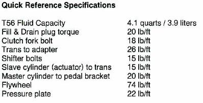
35 Specifications 35
36 Special Thanks A special thanks needs to go out to the forum imapalassforum.com. These guys are a great bunch of individuals and are willing to help in any situation. Thanks to Roger ( Ball ss) Noel (Got CUPCAKE Bearings) Todd (GreenHornet) Gerry (95Wagon) Sean (Ark SS) Sslumpin Imp Sharkx And others, that I am sure that I forgot to mention. 36


37 Impala SS and Caprice T56 Six Speed install guide Supplement A This is an alternate method for the hole in the transmission tunnel and some different steps to take if the catalytic converter hits. 1. trimming the floor - careful use of an F-Body boot can prevent hammering/welding the floor pan - Just trace out the shift boot pattern but shift it as much as it will go to the driver s side. Then cut the floorpan to match the pattern marked previously. Finally punch a new hole for the shifter to the right of the original. This uses the oversize feature of the boot to your advantage. Here is a picture documenting this Floor cut Boot installed 2. The converter hitting the bellhousing can be hit or miss - I ve seen it both ways. If it does hit proceed to step 3 37

38 3. Drop the driver s side cat and oversize the holes with a drill or Dremel. An extra 1/16 at the bolt holes translates to quite a bit more than that at the cat. 4. Then using a belt sander - remove a bit of material from the bellhousing s slave cylinder boss as documented in the next picture. Doing both of these should be enough to get many cars enough clearance that having to cut and re-weld the cat should be unnecessary. Thanks to Jason (JaySS) for this information. 38
Lincoln Mark VII T5 Swap Version submitted by 5.0 bird
 Lincoln Mark VII 1984-1989 T5 Swap Version 20070611 submitted by 5.0 bird I've decided to make an article to assist with the T5 swap for the 84-89 Mark VIIs, since I was just in there because my DOA didn't
4L60E to T56 conversion instructions for LS1 FBody
 4L60E to T56 conversion instructions for 1998-2002 LS1 FBody Modified by Jesse Mock (SSnakekiller), originally written by Alex Afrashteh for instructions on an LT1 Swap. Credits go to Alex Afrashteh for
Installation Instructions for the F2B Pedal Bracket Kit
 Installation Instructions for the F2B Pedal Bracket Kit A. General Information 1. Before you begin, familiarize yourself with this installation procedure. It is assumed that the installer is an experienced
LPE C5 Battery Relocation Kit
 LPE C5 Battery Relocation Kit The LPE C5 Corvette battery relocation kit improves vehicle weight distribution by moving weight to the rear of the vehicle. The improved weight distribution increases traction
Installation Instructions
 Installation Instructions Jeep JK 2-Door (2011 Present) Mounting Bracket and Air Line System Kit for ARB On-Board Twin Air Compressor (CKMTA12) Made in the USA Kit Contents: 1 Flat Bracket 1 Formed Bracket
Installation Instructions
 Installation Instructions Jeep JK Unlimited (2007 Present) Mounting Bracket and Air Line System Kit for ARB On-Board Twin Air Compressor (CKMTA12) Made in the USA Kit Contents: 1 Bracket for ARB Compressor
Connecting the rear fog light on the A4 Jetta, while keeping the 5 Light Mod
 Connecting the rear fog light on the A4 Jetta, while keeping the 5 Light Mod DISCLAIMER: I'm human and make mistakes. If you spot one in this how to, tell me and I'll fix it This was done on my 99.5 Jetta.
PRODUCT USE INFORMATION
 9RC61000 Jeep YJ Body Lift Thank you for choosing Rough Country for all your suspension needs. This body lift fits both manual and Automatic equipped vehicles!!! Refer to last page of this Instruction
BMW 2002 M42 Swap Notes-THIS IS NOT FINISHED
 BMW 2002 M42 Swap Notes-THIS IS NOT FINISHED This document is to help those that want to install an m42 into a BMW 2002. It is based around an e30 engine, trans, and wiring. You can use the e36 block/head/wiring
Tools needed: Here is a pic of the shift kit I used. It is a Transgo brand and as you can see, it just a bag full of springs and one valve.
 Before installing a shift kit, be sure the transmission is in good operating order. If your transmission is making noises, slipping, shifting bad or the fluid looks brown or smells burnt, take the transmission
Exedy Mach 400 Stage 1 Clutch and Pilot Bearing (Late GT, Bullitt, Mach 1; Cobra): SKUs: & 50116
: SKUs: & 50116") Exedy Mach 400 Stage 1 Clutch and Pilot Bearing (Late 01-04 GT, Bullitt, Mach 1; 99-04 Cobra): SKUs: 62502 & 50116 Tools Needed: Car Jack with high lift capabilities (If not, block of wood may be required)
Exedy Mach 400 Stage 1 Clutch and Pilot Bearing (Late 01-04 GT, Bullitt, Mach 1; 99-04 Cobra): SKUs: 62502 & 50116 Tools Needed: Car Jack with high lift capabilities (If not, block of wood may be required)
Preparation. With the car on the ground you will want to:
 Doing a stage 3 swap was a LOT of work Audi S4 Stage 3 (K04) Install Doing a stage 3 swap was a LOT of work. Just a lot of small and simple tasks really. Just make sure you keep track of what you re doing.
Porsche 928 with 16v LH-Jetronic Fuel System
 Porsche 928 with 16v LH-Jetronic Fuel System Toll-Free Tech Hot Line: 877-FOR-928M 877-367-9286 Please do not copy this manual and give copies to your friends. Our ability to bring you this supercharger
Installation Instructions Z-Gate Shifter
 Installation Instructions Z-Gate Shifter Part Number 80681 1998, 2001 by B&M Racing and Performance Products The B&M Z-Gate shifter can be used in vehicles equipped with most popular three speed automatic
Figure 1 Factory G50 update and old Shift Fork Shaft
 911 Clutch Job So you have one of the best 911s there is, a 87-89 G50 Porsche. However, after many years of service, it is time for a clutch. Maybe, the rubber clutch disc has failed, or the clutch is
03-04 Mach 1. Hellion Power Systems Mach 1 Kit Instructions
 Hellion Power Systems 03-04 Mach 1 Kit Instructions Part 1 Hellion recommends that the front suspension system be installed either by trained professionals or by 5.Remove rack bolts K-Member Installation
OEM Cruise Control Installation in GMC/Chevy NBS trucks
 OEM Cruise Control Installation in 99-02 GMC/Chevy NBS trucks May 2008 ~ Rampage_Rick Having just installed factory cruise control in my 00 Sierra, I thought I d share the fun. I followed the steps outlined
99-04 GT. Hellion Power Systems Mustang GT Kit Instructions
 Hellion Power Systems 99-04 Mustang GT Kit Instructions Part 1 Hellion recommends that the front suspension system be installed either by trained professionals or by 5.Remove rack bolts K-Member Installation
5/6 Speed Conversions for Subaru SVX
 5/6 Speed Conversions for Subaru SVX using custom parts available from TomsSVX 4/19/06 Parts list for 5/6mt swap 5/6mt assembly 5/6mt shift linkage(be sure to get all the pieces) 5/6mt starter(both are
Deuce/Ace Installation Instructions
 HARDWARE KIT: Upper Mounting Plate: 2-7/16" (11mm) X 3.5" bolts 2-7/16" flange nuts 2-2" spacers 2-7/16" trim cap mounting washers 2 - plastic trim caps TOOLS NEEDED: safety glasses wrenches 16mm or 5/8"
Our goal is to make the install a breeze. Please read the entire guide before beginning.
 www.airkewld.com Page 1 of 6 IRS Axle Kit Install IRS Axle Kit Install Our goal is to make the install a breeze. Please read the entire guide before beginning. KITS SHOULD INCLUDE 2 - Control-arm mounting
RHINO SUSPENSION SYSTEM INSTALLATION INSTRUCTIONS
 PARTS INCLUDED: 2 FRONT UPPER A-ARMS 2 FRONT LOWER A-ARMS 2 UNI-BALL JOINTS 2 UNI-BALL JOINT STUDS 2 UNI-BALL JOINT CAPS 2 RETAINING RINGS 1 FRONT SHOCK ASSEM. 2 DELRON STEERING STOPS 2 SHOCK MOUNT SPACERS
Note: The transmission mount just happened to be upside down in this picture. (c) 2015 Total Cost Involved Engineering, Inc. All Rights Reserved.
 2015 Total Cost Involved Engineering, Inc. All Rights Reserved.") 1970-1981 Chevy Camaro & Pontiac Firebird Custom IFS Installation Instructions 1-855-693-1259 www.totalcostinvolved.com CHECK ALL PARTS INCLUDED IN THIS KIT TO THE PARTS LIST BEFORE INSTALLATION. IF ANY
1970-1981 Chevy Camaro & Pontiac Firebird Custom IFS Installation Instructions 1-855-693-1259 www.totalcostinvolved.com CHECK ALL PARTS INCLUDED IN THIS KIT TO THE PARTS LIST BEFORE INSTALLATION. IF ANY
WARNING: the engine does not come with oil in it. Please fill the oil before starting. The 200cc hardknock requires 9/10 of a quart of oil.
 WARNING: the engine does not come with oil in it. Please fill the oil before starting. The 200cc hardknock requires 9/10 of a quart of oil. Things needed for assembly. -2 tubes of blue loc-tite. I don
MAZDASPEED3 Intercooler Instructions
 MAZDASPEED3 Intercooler Instructions Congratulations on your purchase of the COBB Tuning Front Mount Intercooler System for your 2007-2009 Mazdaspeed3. The following instructions should assist you through
Prerequisites: Shop Manual (recommended) pages 3-9 through 3-13.
 pages 3-9 through 3-13.") Prerequisites: Order your gaskets average about $25.00 bucks X 2 so $50.00 4NK-11193-00-00 Obtain a shim kit (Should have several 265 and 270s) (Some dealers will exchange) Obtain a Valve Bucket Tool YM-33961
Prerequisites: Order your gaskets average about $25.00 bucks X 2 so $50.00 4NK-11193-00-00 Obtain a shim kit (Should have several 265 and 270s) (Some dealers will exchange) Obtain a Valve Bucket Tool YM-33961
1963 GEN IV SUREFIT VINTAGE AIR CONDITIONING INSTALLATION
 by Randy Irwin 1963 GEN IV SUREFIT VINTAGE AIR CONDITIONING INSTALLATION Randy Irwin - Technical Writer Randy has been involved in the Chevy parts business for over 30 years. He is a wizard at creating,
TJ 231/241 CABLE SHIFTER
 KIT CONSISTS OF: # Qty Part No. Description P.O. Box 247, 4320 Aerotech Center Way PAGE 1 OF 10 Page Rev. Date: 08-29-16 1 1 300474 WASHER-RUBBER YOKE SEAL 32 SPLINE 2 1 300476 NUT- 7/8"-20 FLANGE LOCKNUT
ESS INSTALL. The donor car /6 Cosmos Black/Sand UUC Short Shifter Brembo cross drilled rotors Phillips Nav System 16:9
 ESS INSTALL The donor car.. 1997 540/6 Cosmos Black/Sand UUC Short Shifter Brembo cross drilled rotors Phillips Nav System 16:9 The install went in several stages. Disconnect the battery Stage 1 Remove
Ford AOD-4R70W-AODE Cable Operated Shifter Installation Instructions
 Ford AOD-4R70W-AODE Cable Operated Shifter Installation Instructions Building American Quality With A Lifetime Warranty! TOLL FREE 1-877-469-7440 tech@lokar.com www.lokar.com Ford AOD-4R70W-AODE Cable
1501 Industrial Way N., Toms River, NJ Fax: PACKING LIST MUSTANG LONG TUBE HEADERS (M30000)
") 2/18/04 1501 Industrial Way N., Toms River, NJ 08755 732-349-2109 Fax:732-244-0867 ADVANCED - Installation requires professional-type tools and advanced automotive-service skills. If you lack experience
2/18/04 1501 Industrial Way N., Toms River, NJ 08755 732-349-2109 Fax:732-244-0867 ADVANCED - Installation requires professional-type tools and advanced automotive-service skills. If you lack experience
Installation Directions for FINGER STICK and Blocker Plate
 Installation Directions for FINGER STICK and Blocker Plate What is a Finger Stick? A Finger Stick is a simple circuit that modifies the MAF signal on LLY and LBZ engines (not LB7 engines) to expected levels
Installing Rear Brake Pads on a WK Jeep
 Installing Rear Brake Pads on a WK Jeep Step by Step By Chirpz Disclaimer: I do not claim that this procedure is the right way or even the best way to change your rear brake pads. This is what I did after
Chrysler 727, 904, 518 Floor Mount Automatic Transmission Shifter Installation Instructions
 Chrysler 727, 904, 518 Mount Automatic Transmission Shifter Installation Instructions Building American Quality With A Lifetime Warranty! TOLL FREE 1-877-469-7440 tech@lokar.com www.lokar.com Release Button
Steeda Sport Mustang Lowering Springs (2005+) - Installation Instructions
 - Installation Instructions") Steeda Sport Mustang Lowering Springs (2005+) - Installation Instructions The below installation instructions work for the following products: Steeda Sport Mustang Lowering Springs (2005+) Please read
Steeda Sport Mustang Lowering Springs (2005+) - Installation Instructions The below installation instructions work for the following products: Steeda Sport Mustang Lowering Springs (2005+) Please read
TRANSMISSION INSTALLATION CONTENTS
 A REGAL-BELOIT Company TRANSMISSION INSTALLATION CONTENTS RICHMOND 6-SPEED TRANS AM, CAMARO, CHEVELLE, GTO, CUTLASS, WITH T-10/MUNCIE............2 RICHMOND 6-SPEED 1963 TO 1982 CORVETTE WITH T-10 OR MUNCIE..............................3
Chevy Nova Pro-Touring Front Suspension Installation Instructions
 1962-1967 Chevy Nova Pro-Touring Front Suspension Installation Instructions 1-800-984-6259 www.totalcostinvolved.com 1 Pro-Touring Clip A-Arm Assembly Sway Bar Assembly Fender Panel Kit 8 7/16-20 * 1 ¼
Last Revision: 30JN THRU 1979 C3 CORVETTE STANDARD (NON-ADJUSTABLE) STEERING COLUMN DISASSEMBLY & REPAIR INSTRUCTIONS PAPER #2
 STEERING COLUMN DISASSEMBLY & REPAIR INSTRUCTIONS PAPER #2") Last Revision: 30JN2007 1969 THRU 1979 C3 CORVETTE STANDARD (NON-ADJUSTABLE) STEERING COLUMN DISASSEMBLY & REPAIR INSTRUCTIONS PAPER #2 Disassembly and Repair Instructions Addressed in this Paper Degree
Last Revision: 30JN2007 1969 THRU 1979 C3 CORVETTE STANDARD (NON-ADJUSTABLE) STEERING COLUMN DISASSEMBLY & REPAIR INSTRUCTIONS PAPER #2 Disassembly and Repair Instructions Addressed in this Paper Degree
Automatic Electronic Sport Mode Shifter Installation Instructions
 Automatic Electronic Sport Mode Installation Instructions Building American Quality With A Lifetime Warranty! TOLL FREE 1-877-469-7440 tech@lokar.com www.lokar.com Release Automatic Electronic Sport Mode
04-08 FORD F150 4 KIT
 9257700 04-08 FORD F50 4 KIT THANK YOU FOR CHOOSING ROUGH COUNTRY FOR YOUR SUSPENSION NEEDS. Rough Country recommends a certified technician install this system. In addition to these instructions, professional
CAMARO/FIREBIRD
 CAMARO/FIREBIRD 1967-1969 TKO 5-SPEED MANUAL TO MANUAL TRANSMISSION CONVERSION INSTALLATION MANUAL FOLLOW FACTORY SERVICE MANUAL (FSM) RECOMMENDED SAFETY PRECAUTIONS. TRANSMISSION REMOVAL AND INSTALLATION
96-04 tt. Hellion Power Systems Mustang Twin Turbo Kit Instructions
 96-04 tt Hellion Power Systems 1996-2004 Mustang Twin Turbo Kit Instructions 1. Disconnect battery and elevate front end of car on either Jack stands or a lift if available 2.Lock steering wheel and remove
Z-Gate Universal Shifter
 Installation Instructions Z-Gate Universal Shifter Fits: GM, Ford, Lincoln and Chrysler Transmissions See Application Guide for Specific Applications Part #80681 Rev 06/01/2018 WORK SAFELY! For maximum
INSTALLATION INSTRUCTIONS
 INSTALLATION INSTRUCTIONS FX4 ELITE REAR DISC CONVERSION KITS WITH INTERNAL PARKING BRAKE A110-14, A111-25, A111-29 for FORD 8" & 9" REAR ENDS Thank you for choosing STAINLESS STEEL BRAKES CORPORATION
Return to Instruction Sheet index TCI Installation Instructions for Turbo Hydramatic 350C & 250C
 Page 1 of 6 Return to Instruction Sheet index TCI 326300 Installation Instructions for Turbo Hydramatic 350C & 250C NOTE: This kit was not intended for installation in transmissions that are in poor general
Cable Shift Linkage Kit
 Cable Shift Linkage Kit INSTALLATION INSTRUCTIONS ididit column to GM Trans FOR PART NUMBER S: 2801000010, 2802000010 ididit Column to 350 Trans...Pg 1-4 ididit Column to 400 Trans...Pg 5-8 ididit Column
Ford Racing BOSS 302 Engine Oil Cooler (11-14 GT)
") Tools needed: 14mm hex socket 7mm socket/wrench 8mm socket/wrench Ford Racing BOSS 302 Engine Oil Cooler (11-14 GT) 10mm socket (for airbox removal) ¾ inch or 19mm wrench Torque wrench Appropriate ratchets
Tools needed: 14mm hex socket 7mm socket/wrench 8mm socket/wrench Ford Racing BOSS 302 Engine Oil Cooler (11-14 GT) 10mm socket (for airbox removal) ¾ inch or 19mm wrench Torque wrench Appropriate ratchets
B&M / INTRODUCTION
 INSTALLATION INSTRUCTIONS FOR B&M AUTOMATIC TRANSMISSIONS REPLACING GM TH350, TH400, and TH700R4 / 4L60 (not including 4L60E / electronic shift models) B&M part numbers: 102002-103005 - 107101-107104 107105-107106
Slave Cylinder Weep Hole Drilling Procedure
 Slave Cylinder Weep Hole Drilling Procedure Tools Required: T20 Torx Driver T25 Torx Driver T25 Torx Bit with ¼ Ratchet Wrench 4mm Hex Key (Allen wrench) 5mm Hex Key 6mm Hex Key 8mm Hex Key 12mm Hex Key
Installation Instructions. QuickSilver Shifter. Fits: GM, Ford, Chrysler Transmissions See Application Guide for Specific Applications Part # 80683
 Installation Instructions QuickSilver Shifter Fits: GM, Ford, Chrysler Transmissions See Application Guide for Specific Applications Part # 80683 WORK SAFELY! For maximum safety, perform this installation
1964 1/2-70 Mustang Torque Arm Rear Suspension Installation Instructions
 1964 1/2-70 Mustang Torque Arm Rear Suspension Installation Instructions 1-800-984-6259 www.totalcostinvolved.com Version 2 (c) 2008 Total Cost Involved Engineering, Inc. All Rights Reserved. Page 1 of
Mustang Radiator Conversion DIY. By GearHeadPeter. January 27, 2011
 1964-1966 Mustang Radiator Conversion DIY By GearHeadPeter January 27, 2011 We all know that the radiators in our cars are not the best, especially if you have done any customization to the engine, which
Nissan Pathfinder (R50) Automatic to Manual Transmission Conversion Manual
 Automatic to Manual Transmission Conversion Manual") 1996 1999 Nissan Pathfinder (R50) Automatic to Manual Transmission Conversion Manual 1 1996 1999 Nissan Pathfinder (R50) Automatic to Manual Transmission Conversion Manual Conversion performed and Manual
1996 1999 Nissan Pathfinder (R50) Automatic to Manual Transmission Conversion Manual 1 1996 1999 Nissan Pathfinder (R50) Automatic to Manual Transmission Conversion Manual Conversion performed and Manual
Step 6: Remove and save the MAP sensor for later use. Step 7: Remove the passenger side intercooler pipe and the EGR intake manifold.
 LBZ Twin kit Install Step 1: Disconnect both batteries. Step 2: Drain coolant and oil also remove passenger side inner fender. Step 3: Remove intake box and piping. (Remove and save the MAF sensor in the
Self-Adjust Clutch Installation Guide
 Self-Adjust Clutch Installation Guide 0 STOP! READ CAREFULLY BEFORE INSTALLING CLUTCH This clutch must be installed by a qualified installer. Improper installation or failure to replace or resurface the
Installation Instructions Unimatic Shifter
 Installation Instructions Unimatic Shifter Universal Shifter for Automatic Transmissions Part Number 80775 2010, 2000 by B&M Racing & Performance Products The B&M Unimatic is a universal shifter that will
Hard Bar Sport, M1/M2 Hard Core Hardtop, M2 Sport, and Xtreme Installation Instructions
 HARDWARE KIT: Hard Bar Sport, M1/M2 Hard Core Shoulder Harness Guide Relocation Assemblies: 2-3/8" X 1" grade 8 bolts 4-3/8" flat washers 2-3/8" lock nuts 2 - brass bushings 2 - plastic trim caps 2-3/8"
DrVanos.com Stage II Installation Instructions. Tool rental is available with the purchase of a vanos kit *See website for more info*
 DrVanos.com Stage II Installation Instructions Special Tools Needed: Camshaft locking tool TDC Crank pin Sprocket turning tool Tool rental is available with the purchase of a vanos kit *See website for
Depress each tab as you pull the bezel off. The bezels are tight. L.H. shown.
 2013-2014 Ford Mustang V6 & Boss 302 Lower Valance Fog Light Kit Parts List: Quantity: Tool List: Fog light & bulb with bracket 2 Flat head & Phillips screwdriver Black bezels 2 Ratchet & Socket set OR
I. Before starting installation
 5. Park the vehicle on a clean, dry, flat, level surface and block the tires so the vehicle cannot roll in either direction. A. Disconnect battery cables 1. Disconnect the negative cable first, then the
INSTALLATION INSTRUCTIONS DODGE DAKOTA 2 KIT # 682 (2WD), 692 (4WD) 3 KIT # 683 (2WD), 693 (4WD)
, 692 (4WD) 3 KIT # 683 (2WD), 693 (4WD)") INSTALLATION INSTRUCTIONS 1997-1999 DODGE DAKOTA 2 KIT # 682 (2WD), 692 (4WD) 3 KIT # 683 (2WD), 693 (4WD) Installation of a Performance Accessories body lift kit will change the vehicle s center of gravity
INSTALLATION INSTRUCTIONS 1997-1999 DODGE DAKOTA 2 KIT # 682 (2WD), 692 (4WD) 3 KIT # 683 (2WD), 693 (4WD) Installation of a Performance Accessories body lift kit will change the vehicle s center of gravity
Procharger Stage II Intercooled Supercharger System (11-14 GT)
") Procharger Stage II Intercooled Supercharger System (11-14 GT) Installation Time: Approximately one day. Installed on 2012 Mustang GT 5.0/Manual Required Tools 3/8 Socket Set (Standard and Metric) 1/2
Procharger Stage II Intercooled Supercharger System (11-14 GT) Installation Time: Approximately one day. Installed on 2012 Mustang GT 5.0/Manual Required Tools 3/8 Socket Set (Standard and Metric) 1/2
2014 F /6 LIFT KIT
 92157500 2014 F-150 4 /6 LIFT KIT THANK YOU FOR CHOOSING ROUGH COUNTRY FOR YOUR SUSPENSION NEEDS. Rough Country recommends a certified technician install this system. In addition to these instructions,
Detroit Speed, Inc. Selecta-Speed Wiper Kit Corvette P/N:
 Detroit Speed, Inc. Selecta-Speed Wiper Kit 1968-72 Corvette P/N: 121621 A downpour of rain will no longer hinder your ability to clearly see the road. The Detroit Speed Selecta-Speed Wiper Kit provides
INSTALLATION INSTRUCTIONS
 COLD AIR INTAKE INSTALLATION INSTRUCTIONS PART NUMBER D760-0390C APPLICATION: 1999-2003 E39 M5 PARTS LIST 1 Left Aluminum Intake Tube 1 Air Pump Bracket (A) 1 Right Aluminum Intake Tube 1 Air Pump Bracket
Mustang CDC Lightbar (94-04) - Installation Instructions
 - Installation Instructions") Mustang CDC Lightbar (94-04) - Installation Instructions The below installation instructions work for the following products: Classic Design Concepts Mustang Convertible Lightbar (94-04 Carbon Fiber) Classic
Mustang CDC Lightbar (94-04) - Installation Instructions The below installation instructions work for the following products: Classic Design Concepts Mustang Convertible Lightbar (94-04 Carbon Fiber) Classic
ADVANCE ADAPTERS INC. P/N: TJ 231/241 CABLE SHIFTER
 Paso Robles, CA 93447 PAGE 1 of 10 Telephone: (800) 350-2223 Fax: (805) 238-4201 Page Rev. Date: 09-25-15 KIT CONSISTS OF: # Qty Part No. Description 1 1 300474 WASHER-RUBBER YOKE SEAL 32 SPLINE 2 1 300476
1209A GM B-BODY Double Adjustable Trailing Arms
 1209A 78-96 GM B-BODY Double Adjustable Trailing Arms Warning: This installation should be performed by a trained professional. Tools Required for this Installation - 4 post lift or alignment rack preferable
Installation Instructions and Suggestions For Jeep YJ Fiberglass Replacement Bodies
 Installation Instructions and Suggestions For Jeep YJ Fiberglass Replacement Bodies Getting started with the removal of your existing Jeep body. Trust nothing to memory; take photos of everything at different
Ford C4 and C6 Floor Mount Automatic Transmission Shifter Installation Instructions
 Ford C4 and C6 Mount Automatic Transmission Shifter Installation Instructions Building American Quality With A Lifetime Warranty! TOLL FREE 1-877-469-7440 tech@lokar.com www.lokar.com Ford C4 and C6 Mount
Torqueflite Manual/Automatic Valve Body
 TCI 122400 Torqueflite Manual/Automatic Valve Body This valve body can be installed in a few hours by carefully following directions. Read all instructions first to familiarize yourself with the parts
2010 Toyota Prius Fog Light Retrofit
 2010 Toyota Prius Fog Light Retrofit A DIY prospective Last updated: Friday, December 25, 2009 *** Disclaimer Use this document and its contents at your own risk! *** Forward: This document was compiled
v Porsche 928
 1985-86 32v Porsche 928 Toll-Free Tech Hot Line: 877-FOR-928M 877-367-9286 Please do not copy this manual and give copies to your friends. Our ability to bring you this supercharger kit at this price relies
04-08 FORD F150 6 KIT
 957600 THANK YOU FOR CHOOSING ROUGH COUNTRY FOR YOUR SUSPENSION NEEDS. 0-08 FORD F50 6 KIT Rough Country recommends a certified technician install this system. In addition to these instructions, professional
Short-throw Shifter Installation Guide
 Short-throw Shifter Installation Guide Removal Procedure 1) Remove the shift control knob. A. Lift up on the rear portion of the shift control closeout boot retaining ring and detach the retaining ring
TCI FastGate Shifter Installation Instructions
 151 INDUSTRIAL DRIVE ASHLAND, MISSISSIPPI 38603 http://www.tciauto.com TELEPHONE: 662-224-8972 FAX LINE: 662-224-8255 E-MAIL: tech@tciauto.com TCI 616541 FastGate Shifter Installation Instructions The
Z1 Motorsports 370Z/G37 Oil Cooler Kit Installation Manual
 Z1 Motorsports 2877 Carrollton Villa Rica Hwy Carrollton GA 30116 770.838.7777 Z1 Motorsports 370Z/G37 Oil Cooler Kit Installation Manual For 19, 25 and 34 Row Oil Cooler Kits Parts Included: 1 SETRAB
67-70 Cougar Rack Kit Instructions # &
 67-70 Cougar Rack Kit Instructions # 8011950-01 & 8011940-01 Unisteer offers a limited warranty against all manufacturer defects of their kits and supplied parts. Unisteer will not honor any warranty on
*1576BAG9* 1576BAG FORD F KIT C THANK YOU FOR CHOOSING ROUGH COUNTRY FOR YOUR SUSPENSION NEEDS.
 957600C THANK YOU FOR CHOOSING ROUGH COUNTRY FOR YOUR SUSPENSION NEEDS. 0-08 FORD F50-6 KIT Rough Country recommends a certified technician install this system. In addition to these instructions, professional
GM Floor Mount Automatic Transmission Shifter Installation Instructions
 GM Mount Automatic Transmission Shifter Installation Instructions Building American Quality With A Lifetime Warranty! TOLL FREE 1-877-469-7440 tech@lokar.com www.lokar.com GM Mount Automatic Transmission
POWER RACK AND PINION STEERING INSTALLATION
 by Randy Irwin 1955-57 POWER RACK AND PINION STEERING INSTALLATION Randy Irwin - Technical Writer Randy has been involved in the Chevy parts business for over 25 years. He is a wizard at creating, making
CORVETTE TKO 5-SPEED MANUAL TO MANUAL TRANSMISSION CONVERSION INSTALLATION MANUAL
 CORVETTE 1984 1988 TKO 5-SPEED MANUAL TO MANUAL TRANSMISSION CONVERSION INSTALLATION MANUAL FOLLOW FACTORY SERVICE MANUAL (FSM) RECOMMENDED SAFETY PRECAUTIONS. TRANSMISSION REMOVAL AND INSTALLATION IS
Installation Instructions COMPETITION/PLUS SHIFTER Ford Mustang MT82 6-Speed Manual Transmission Catalog#
 Installation Instructions COMPETITION/PLUS SHIFTER 2015-2017 Ford Mustang MT82 6-Speed Manual Transmission Catalog# 3916037 Rev. 00 WORK SAFELY! For maximum safety, perform this installation on a clean,
1986 Rear Disk Brake Upgrade. All hard lines mounted to the rear axle with mounting screws. 1/4" fittings
 1986 Rear Disk Brake Upgrade Being well prepared for a project of this size is the key to success. I thought I was well prepared by doing a lot of research and getting all of the required parts before
Steeda S550 MT-82 Tri-Ax Race Short Throw Shifter Installation Instructions For Parts: ,
 Steeda S550 MT-82 Tri-Ax Race Short Throw Shifter Installation Instructions For Parts: 555-7317, 555-7318 Tools required 1. 7mm socket 2. 10mm socket 3. 13mm socket 4. 15mm socket 5. 18mm socket 6. 3/8
09-UP FORD F150 6 LIFT KIT
 92159800 09-UP FORD F150 6 LIFT KIT THANK YOU FOR CHOOSING ROUGH COUNTRY FOR YOUR SUSPENSION NEEDS. Rough Country recommends a certified technician install this system. In addition to these instructions,
DODGE DAKOTA 3 BODY LIFT INSTALLATION INSTRUCTIONS KIT # 60153
 DODGE DAKOTA 3 BODY LIFT INSTALLATION INSTRUCTIONS 2003-04 KIT # 60153 Installation of a Performance Automotive Group body lift kit will change the vehicle s center of gravity and handling characteristics
Ford AOD-4R70W-AODE Cable Operated Shifter Installation Instructions
 Ford AOD-4R70W-AODE Cable Operated Shifter Installation Instructions Building American Quality With A Lifetime Warranty! TOLL FREE 1-877-469-7440 tech@lokar.com www.lokar.com Ford AOD-4R70W-AODE Cable
Installation Guide for Rough Country 2.5 inch Lift Kit w/o Shocks (07-15 Wrangler JK) Item # J10212
 Item # J10212") Installation Guide for Rough Country 2.5 inch Lift Kit w/o Shocks (07-15 Wrangler JK) Item # J10212 Installation Time: 3 Hours Tools Required: Jack (2 helps, but not needed) Jack stands(2 3-ton, 2 2-ton)
Installation Guide for Rough Country 2.5 inch Lift Kit w/o Shocks (07-15 Wrangler JK) Item # J10212 Installation Time: 3 Hours Tools Required: Jack (2 helps, but not needed) Jack stands(2 3-ton, 2 2-ton)
TCI Trans-Scat
 Page 1 of 5 Return to Instruction Sheet index TCI 350000 Trans-Scat Installation Instructions For TURBO HYDRAMATIC 350 This kit will allow you to reprogram your transmission to meet your driving needs
Stand Alone Fog Lights Installation Instructions
 Tools Required: 1. Trim Removal tool or protected flat screwdriver 2. #2 Phillips Screwdriver 3. 10mm socket 4. 10mm wrench 5. 8mm or 5/16 socket 6. Adjustable Pliers 7. Electrical Tape WARNING!!! Disconnect
Installation Instructions Right Hand Drive Megashifter
 Installation Instructions Right Hand Drive Megashifter Part Number 80685 1995, 2001, 2006, 2010 by B&M Racing & Performance Products The B&M Right Hand Drive Megashifter is designed specifically for vehicles
Replacing MK4 Golf/Jetta radiator mounts in-car
 Replacing MK4 Golf/Jetta radiator mounts in-car This is a guide to replacing the radiator mounts in a MK4 Golf/Jetta. This involves moving the core support to the service position which allows you to do
Changing the Struts on a WK Jeep CRD
 Changing the Struts on a WK Jeep CRD Step by Step By Chirpz Disclaimer: I do not claim that this procedure is the right way or even the best way to change your struts. This is what I did after reading
Installation Instructions Unimatic Shifter
 Installation Instructions Unimatic Shifter Universal Shifter for Automatic Transmissions Part Number 80775 2000 by B&M Racing & Performance Products LLC The B&M Unimatic is a universal shifter that will
VW & Audi TDI CR140 ECO KIT Installation Guide
 VW & Audi TDI CR140 ECO KIT Installation Guide This guide is to help you install your new Rawtek DPF, EGR & Adblue Delete Exhaust ECO Kit on your (2009-2014) VW / Audi with 2.0l CR140 Diesel Engine. Note:
Remove black panel shown. Save 6 retaining pins for re-install later. Pry up on center part of pin first. Then pry out entire retaining pin.
 2005-2009 Ford Mustang V6 Fog Light Wiring Kit Parts List: Quantity: Tools Required: Wiring harness 1 Flat head screwdriver Supplemental wire leads 2 Ratchet & Socket set OR Wire tap red 2 Adjustable Wrench
Clutch Installation Guide
 Clutch Installation Guide 0 STOP! READ CAREFULLY BEFORE INSTALLING CLUTCH This clutch must be installed by a qualified installer. Improper installation or failure to replace or resurface the flywheel,
Hurst VMATIC3 INSTALLATION
 FORM 159 8530 07/12 Hurst VMATIC3 3-Speed & 4-Speed Automatic Shifter Catalog #3838530 2012 by Hurst Performance The Hurst Vmatic3 shifter can be used in vehicles equipped with most popular three speed
Light Truck MegaShifter
 Installation Instructions Light Truck MegaShifter The B&M Light Truck Megashifter shifter is designed to be used in most light trucks equipped with most popular three speed or four speed automatic transmissions.