TEST REPORT IEC Low-voltage switchgear and control gear Part 7-4: Ancillary equipment PCB terminal blocks for copper conductors
|
|
|
- Ross Howard
- 6 years ago
- Views:
Transcription
1
2


3
4 r Test Report issued under the responsibility of: TEST REORT Low-voltage switchgear and control gear art 7-4: Ancillary equipment CB terminal blocks for copper s Report Number.... : Date of issue... : Total number of pages pages Applicant s name... : Address... : WAGO Kontakttechnik GmbH & Co. KG Hansastrasse 27, Minden, Germany Test specification: Standard... : Test procedure... : Non-standard test method... : : 2013 (First Edition) CB Scheme Test Report Form No.... : Test Report Form(s) Originator... : IEC60947_7_4B Master TRF... : Dated VDE Testing and Certification Institute Copyright 2014 IEC System of Conformity Assessment Schemes for Electrotechnical Equipment and Components (IECEE System). All rights reserved. This publication may be reproduced in whole or in part for non-commercial purposes as long as the IECEE is acknowledged as copyright owner and source of the material. IECEE takes no responsibility for and will not assume liability for damages resulting from the reader's interpretation of the reproduced material due to its placement and context. If this Test Report Form is used by non-iecee members, the IECEE/IEC logo and the reference to the CB Scheme procedure shall be removed. This report is not valid as a CB Test Report unless signed by an approved CB Testing Laboratory and appended to a CB Test Certificate issued by an NCB in accordance with IECEE 02. General disclaimer: The test results presented in this report relate only to the object tested. This report shall not be reproduced, except in full, without the written approval of the Issuing CB Testing Laboratory. The authenticity of this Test Report and its contents can be verified by contacting the NCB, responsible for this Test Report.

5
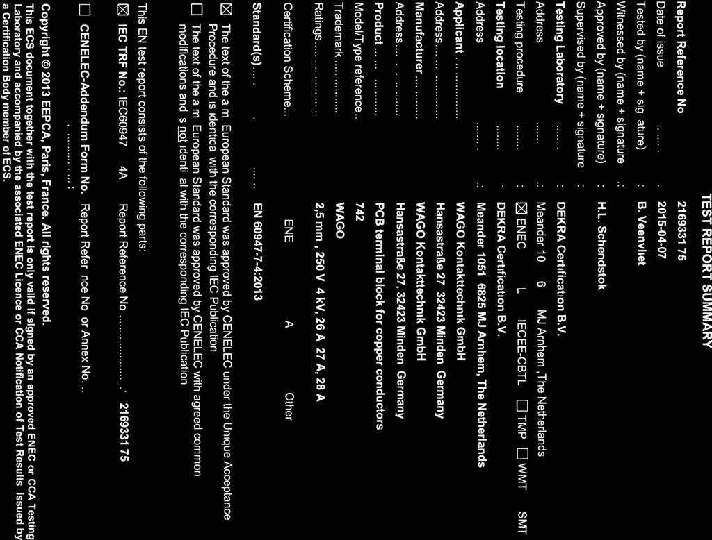
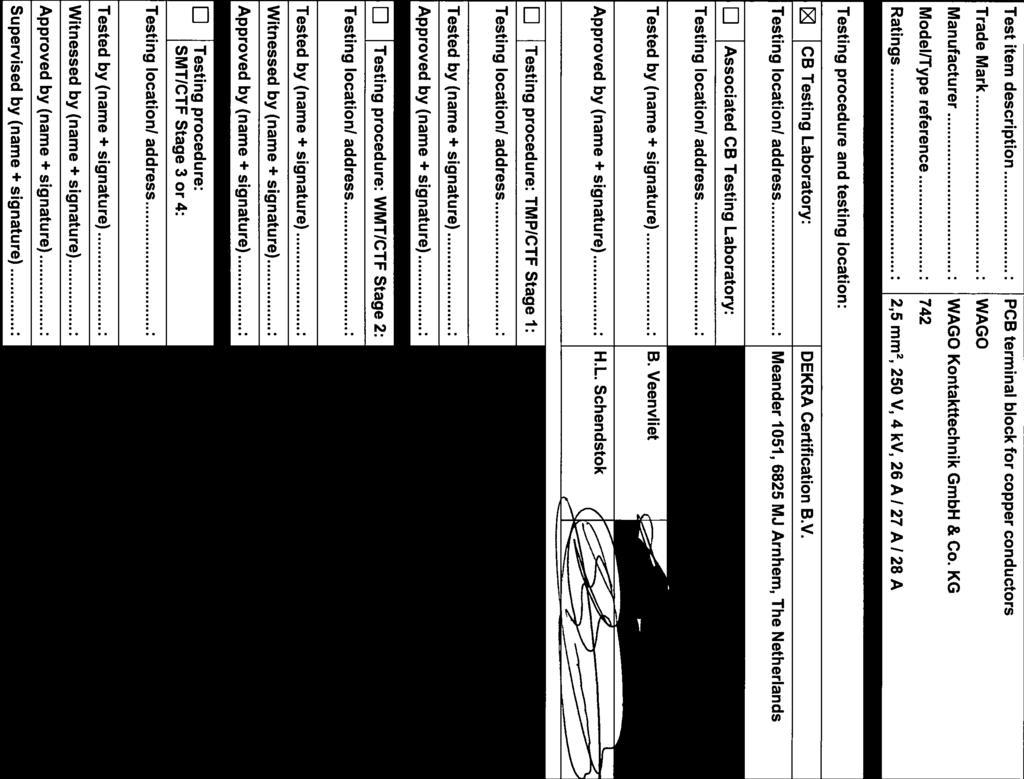
6 age 3 of 58 Report No List of Attachments (including a total number of pages in each attachment): Attachments: test report according to IEC Summary of testing: Tests performed (name of test and test clause): Complete investigation. All test are carried out at type , and unless otherwise stated Testing location: DEKRA Certification B.V. Meander 1051, 6825 MJ Arnhem, The Netherlands Summary of compliance with National Differences: List of countries addressed The product fulfils the requirements of (insert standard number and edition and delete the text in parenthesis, leave it blank or delete the whole sentence, if not applicable) Copy of marking plate: The artwork below may be only a draft. The use of certification marks on a product must be authorized by the respective NCBs that own these marks. 742
7 age 4 of 58 Report No Test item particulars...: Classification of installation and use...: Supply Connection...: articulars: test item vs. test requirements - type of clamping units...: screwless-type clamping unit - ability to accept prepared s...: unprepared s ( and rigid) - type of electrical contact to the printed circuit board...: solder pins - type of mechanical fastening to the printed circuit board...: - number of poles...: 1 pole - pitch (centre to centre pin spacing)...: 5 mm and 5,08 mm - contact units with identical or dissimilar clamping units...: identical - number of clamping units on each contact unit..: 1 up to and including 3 screwless clamping unit - standard cross-section (mm²)...: 2,5 mm² - maximum cross-section (mm²)...: 2,5 mm² - connecting capacity (mm²)...: 0,08 mm² - 2,5 mm² rigid and - rated insulation voltage U i (V)...: 250/500 V - rated impulse withstand voltage U imp (kv)...: 4 kv - rated current (A)...: 26 A / 27 A / 28 A at an ambient temperature of 40 C and a reduction factor of 0,8 - reduction factor if other than 0,8...: - upper limiting temperature ( C)...: 105 C - lower limiting temperature ( C)...: - 60 C - ambient temperature ( C) if other than 40 C...: ossible test case verdicts: - test case does not apply to the test object... : - test object does meet the requirement... : (ass) - test object does not meet the requirement... : F (Fail) Testing... : Date of receipt of test item... : Date (s) of performance of tests... : General remarks: "(See Enclosure #)" refers to additional information appended to the report. "(See appended table)" refers to a table appended to the report. Throughout this report a comma / point is used as the decimal separator.
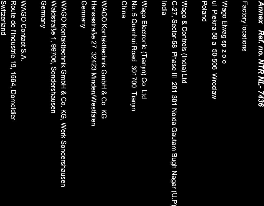
8 age 5 of 58 Report No Manufacturer s Declaration per sub-clause of IECEE 02: The application for obtaining a CB Test Certificate includes more than one factory location and a declaration from the Manufacturer stating that the sample(s) submitted for evaluation is (are) representative of the products from each factory has been provided... : Yes Not applicable When differences exist; they shall be identified in the General product information section. Name and address of factory (ies)... : General product information: Wago Elwag sp.z.o.o. ul. iekna 58 a, , Wroclaw oland Wago & Controls (India) Ltd. C-27, Sector-58, hase III, Noida Gautam Bugh Nagar (U.) India Wago Electronic (Tianjin) Co. Ltd. No. 5 Quanhui Road, , Tianjin China WAGO Kontakttechnik GmbH & Co. KG Hansastraße 27, Minden/Westfalen Germany WAGO Kontakttechnik GmbH & Co. KG, Werk Sondershausen Waldstraße 1, 99706, Sondershausen Germany WAGO Contact S.A. Route de l Industrie 19, 1564, Domdidier Switzerland See page 41 and 42
9 age 6 of 58 Report No MARKING CB Terminal block shall be marked with: - manufacturer's name or trademark - type designation Very small CB terminal blocks with a surface 742 which cannot be marked shall be marked only according to a). In those cases all specified information shall be marked on the smallest packing unit. 5.2 The following information shall be stated by the manufacturer if applicable, e.g. in the manufacturer's data sheet, or his catalogue or on the packing unit: - manufacturer's claim for compliance with (catalogue) IEC maximum cross-section 2,5 mm² (catalogue) - connecting capacity 0,08 mm² - 2,5 mm² rigid and (catalogue) - rated current and the reduction factor to 26 / 27/ 28 A (catalogue) determine the derating curve if different from 0,8 - rated insulation voltage (U i ) 250/500 V (catalogue) - rated impulse withstand voltage (U imp ) - Service conditions if different from those of Cl special preparation of the end of the 4 kv (catalogue) 6. Normal service, mounting and transport conditions Clause 6 of IEC :2007 applies. 7. CONSTRUCTIONAL AND ERFORMANCE REQUIREMENTS 7.1 Constructional requirements Clamping units
10 age 7 of 58 Report No Clamping units shall allow the s to be connected by means ensuring that a reliable mechanical linkage and electrical contact is properly maintained. No contact pressure shall be transmitted through insulating materials other than ceramic Clamping units and connecting methods listed in Table 3 fulfil the requirements of this standard a) Screw-type clamping unit IEC or IEC b) Screwless-type clamping unit IEC or IEC or IEC c) Wrapped connection IEC d) Crimped connection IEC e) Insulation displacement connection (accessible) IEC or IEC f) Insulation displacement connection (nonaccessible) IEC or IEC g) ress-in connection IEC h) Insulation piercing connection IEC or IEC i) Flat quick-connect termination IEC61210 j) Soldered connection IEC Mounting and installation CB terminal blocks shall be so designed that safe soldering mounting on a printed circuit board is possible by means of soldering, pressing-in, screwing, etc. The connection to the printed circuit board shall not be damaged by connecting the s. Test in accordance with Clearances and creepage distances Values for clearances and creepage distances are given in Tables 13 and 15 of IEC
11 age 8 of 58 Report No Terminal identification and marking: CB terminal blocks shall have provision, or at least space, for identification marks or numbers for each clamping unit or contact unit related to the circuit of which it is to form a part or physically not possible, at data sheet or catalogue Resistance to abnormal heat and fire Glow-wire test on complete product according to 8.5 or for insulation materials in accordance with: IEC , GWFI at 850 C and IEC , GWIT at 775 C See Maximum cross-section and maximum connecting capacity CB terminal blocks are so designed that s of the maximum cross-section and/or 0,08 mm² - 2,5 mm² rigid and the maximum connecting capacity can be accepted. Compliance is checked by the test described in The verification of the maximum cross-section may be performed by the special test according to erformance requirements Temperature rise CB terminal blocks shall be tested in accordance with The sum of ambient temperature and temperature rise shall not exceed the upper limiting temperature (ULT) Dielectric properties If manufacturer declared rated impulse withstand 105 ºC 4 kv voltage (U imp ), test in accordance with a) For the verification of solid insulation, the test shall carried out in accordance with b) test voltage is selected from category III 250 V / 500 V U test 3,1 kv V
12 age 9 of 58 Report No Short-time withstand current test CB terminal blocks shall withstand for 1s a current of 120A/mm² in accordance with The test shall be performed using the smallest cross-section in the current path of the contact unit as declared by the manufacturer Contact When measured according to 8.4.4, the change in contact of a CB terminal block, caused by connection and mounting on the CB, shall not exceed the permissible deviations specified in Ageing test (climatic sequence and corrosion test) Compliance checked by test described in Electromagnetic compatibility (EMC) Subclause 7.3 of IEC :2007, Amendment 1 (2010) applies. Solder pin Cross-section see 8.4.6
13 age 10 of 58 Report No TESTS 8.3 Verification of mechanical characteristics Attachment of the CB terminal block on its support maximum cross-section (mm²) / type... : 2,5 mm² diameter of thread (mm)... : - torque (Nm)... : - number of poles, preferably two poles... : 1 pole After verification of contact, the shall connected and disconnected five times See appended table Verification of contact before and after mechanical strength test contact before mechanical strength test See appended table after the mechanical strength test the contact shall not rise by more than 50% of the See appended table initial measurement value. If the measurement value exceeds 1,5 times the initial measurement value, the clamping units and the connecting methods may be evaluated separately. After the test the terminal assembly shall be free from damage which may impair further use Verification of the maximum cross-section and connecting capacity The mechanical properties of clamping units are See appended table tested according to the applicable connecting methods listed in Table Verification of maximum cross-section (special test with gauges) Subclause of IEC , applies with the following addition. The test shall be carried out on each clamping unit of one CB terminal block. 8.4 Verification of electrical characteristics Verification of clearances and creepage distances CB terminal blocks connected with the most unfavourable type 2,5 mm² solid
14 age 11 of 58 Report No Conductor end length (mm) 6 7 mm Clearances (type ) Rated impulse withstands voltage, U imp (kv)... : ollution degree..: Case A (mm)... : Case B (mm)... : (mm)... : Creepage distances: (type ) Rated insulation voltage, U i (V)... : Comparative tracking index (V)..: Material group : ollution degree..: Minimum creepage distances (mm)..: creepage distances (mm)... : Clearances (type ) Rated impulse withstands voltage, U imp (kv)... : ollution degree..: Case A (mm)... : Case B (mm)... : (mm)... : Creepage distances: (type ) Rated insulation voltage, U i (V)... : Comparative tracking index (V)..: Material group : ollution degree..: Minimum creepage distances (mm)..: creepage distances (mm)... : Clearances (type ) Rated impulse withstands voltage, U imp (kv)... : ollution degree..: Case A (mm)... : Case B (mm)... : (mm)... : 4 kv 3 and 2 3 mm 1,2 mm 4,3 mm 250 V, 500 V 600 V I 3, 2 3,2 mm, 2,5 mm 4,31 mm 4 kv 3 and 2 3 mm 1,2 mm 4,3 mm 250 V, 500 V 600 V 1 3, 2 3,2 mm, 2,5 mm 4,3 mm 4 kv 3 and 2 3 mm 1,2 mm 4,3 mm
15 age 12 of 58 Report No Creepage distances: (type ) Rated insulation voltage, U i (V)... : Comparative tracking index (V)..: Material group : ollution degree..: Minimum creepage distances (mm)..: creepage distances (mm)... : 250 V, 500 V 600 V 1 3, 2 3,2 mm, 2,5 mm 4,3 mm Dielectric tests (type ) Impulse withstand voltage test Uimp indicated by the manufacture Unfavourable cross-section (mm²) / type / 2,5 mm² / 6-7 mm end length (mm)... : Rated impulse withstand voltage (kv)... : Impulse withstand voltage in accordance with 4 kv 4,8 kv Table 4 ower-frequency withstand voltage test Unfavourable cross-section (mm²) / type / end length (mm)... : 2,5 mm² / 6 7 mm Rated insulation voltage U i (V)... : 250 V, 500 V Overvoltage category... : III ower-frequency withstand verification of solid insulation in accordance with Table 5 3,1 kv Dielectric tests (type ) Impulse withstand voltage test Uimp indicated by the manufacture Unfavourable cross-section (mm²) / type / 2,5 mm² / 6-7 mm end length (mm)... : Rated impulse withstand voltage (kv)... : Impulse withstand voltage in accordance with 4 kv 4,8 kv Table 4 ower-frequency withstand voltage test Unfavourable cross-section (mm²) / type / end length (mm)... : 2,5 mm² / 6-7 mm Rated insulation voltage U i (V)... : 250 V, 500 V
16 age 13 of 58 Report No Overvoltage category... : ower-frequency withstand verification of solid III 3,1 kv insulation in accordance with Table Dielectric tests (type ) Impulse withstand voltage test Uimp indicated by the manufacture Unfavourable cross-section (mm²) / type / 2,5 mm² / 8-9 mm end length (mm)... : Rated impulse withstand voltage (kv)... : Impulse withstand voltage in accordance with 4 kv 4,8 kv Table 4 ower-frequency withstand voltage test Unfavourable cross-section (mm²) / type / end length (mm)... : 2,5 mm² / 8-9 mm Rated insulation voltage U i (V)... : 250 V, 500 V Overvoltage category... : III ower-frequency withstand verification of solid insulation in accordance with Table 5 3,1 kv Temperature-rise test (type ) Temperature-rise conditions: Upper limiting temperature ( C)... : Ambient temperature ( C)... : used rinted circuit board... : The sum of cross-sections of interconnections shall 105 C 21,5 C grid 5 mm 2 x 1 mm² not exceed the rated cross section Unless otherwise specified, the test shall be carried out according to IEC The upper limiting temperature specified for the See appended table specimen is not exceeded Verification of contact before and after temperature-rise test contact before temperature-rise test See appended table after the temperature-rise test the contact See appended table shall not rise by more than 50% of the initial measurement value.
17 age 14 of 58 Report No If the measurement value exceeds 1,5 times the initial measurement value, the clamping units and the connecting methods may be evaluated separately Temperature-rise test (type with connection bridge) Temperature-rise conditions: Upper limiting temperature ( C)... : Ambient temperature ( C)... : used rinted circuit board... : The sum of cross-sections of interconnections shall not exceed the rated cross section 105 C 21,5 C grid 5 mm Unless otherwise specified, the test shall be carried out according to IEC The upper limiting temperature specified for the See appended table specimen is not exceeded Verification of contact before and after temperature-rise test contact before temperature-rise test See appended table after the temperature-rise test the contact See appended table shall not rise by more than 50% of the initial measurement value. If the measurement value exceeds 1,5 times the initial measurement value, the clamping units and the connecting methods may be evaluated separately Temperature-rise test (type ) Temperature-rise conditions: Upper limiting temperature ( C)... : Ambient temperature ( C)... : used rinted circuit board... : The sum of cross-sections of interconnections shall 105 C 22,7 C grid 5 mm 2 x 1 mm² not exceed the rated cross section Unless otherwise specified, the test shall be carried out according to IEC The upper limiting temperature specified for the See appended table specimen is not exceeded Verification of contact before and after temperature-rise test
18 age 15 of 58 Report No contact before temperature-rise test See appended table after the temperature-rise test the contact See appended table shall not rise by more than 50% of the initial measurement value. If the measurement value exceeds 1,5 times the initial measurement value, the clamping units and the connecting methods may be evaluated separately Temperature-rise test (type ) Temperature-rise conditions: Upper limiting temperature ( C)... : Ambient temperature ( C)... : used rinted circuit board... : The sum of cross-sections of interconnections shall 105 C 22,7 C grid 5 mm 2 x 1 mm² not exceed the rated cross section Unless otherwise specified, the test shall be carried out according to IEC The upper limiting temperature specified for the See appended table specimen is not exceeded Verification of contact before and after temperature-rise test contact before temperature-rise test See appended table after the temperature-rise test the contact See appended table shall not rise by more than 50% of the initial measurement value. If the measurement value exceeds 1,5 times the initial measurement value, the clamping units and the connecting methods may be evaluated separately Short-time withstand current test (type ) Maximum cross-section of the (mm²). : Torque (Nm)... : Test current (A)... : Duration of the test current (s)... : 2,5 mm² - 0,91 x 1,03 x 120 = 112 A 1 sec
19 age 16 of 58 Report No At the end of the test, assembly shall show no interruption and the CB terminal blocks shall be free from cracks, rupture or other critical damage Verification of contact before and after short-time withstand current test contact before short-time withstand See appended table current test after the short-time withstand current test the contact shall not rise by more than 50% of the initial measurement value. If the measurement value exceeds 1,5 times the initial measurement value, the clamping units and the connecting methods may be evaluated separately Short-time withstand current test (type ) Maximum cross-section of the (mm²). : Torque (Nm)... : Test current (A)... : Duration of the test current (s)... : At the end of the test, assembly shall show no interruption and the CB terminal blocks shall be free from cracks, rupture or other critical damage See appended table ,5 mm² - 0,86 x 1,05 x 120 = 108 A 1 sec Verification of contact before and after short-time withstand current test contact before short-time withstand See appended table current test after the short-time withstand current test the contact shall not rise by more than 50% of the initial measurement value. If the measurement value exceeds 1,5 times the initial measurement value, the clamping units and the connecting methods may be evaluated separately Short-time withstand current test (type ) Maximum cross-section of the (mm²). : Torque (Nm)... : See appended table ,5 mm² -
20 age 17 of 58 Report No Test current (A)... : Duration of the test current (s)... : At the end of the test, assembly shall show no interruption and the CB terminal blocks shall be free from cracks, rupture or other critical damage 1,06 x 0,88 x 120 = 111,6 A 1 sec Verification of contact before and after short-time withstand current test contact before short-time withstand See appended table current test after the short-time withstand current test the contact shall not rise by more than 50% of the initial measurement value. If the measurement value exceeds 1,5 times the initial measurement value, the clamping units and the connecting methods may be evaluated separately. See appended table Ageing test (climatic sequence and corrosion test) (type ) Cold storage in accordance with IEC , Test 11j Test duration (h)...: 2 h Lower limiting temperature (LLT)...: - 60 C Visual inspection, CB terminal blocks shall be free from cracks, rupture or other critical damage Dry heat in accordance with IEC , Test 11i Test duration (h)...: 168 h Upper limiting temperature (ULT)...: 105 C Visual inspection, CB terminal blocks shall be free from cracks, rupture or other critical damage rotection against corrosion Flowing mixed gas corrosion in accordance with IEC , test 11g, Method 1 or Method 4 (Table 1 of IEC ) Test duration is 4 days.
21 age 18 of 58 Report No Sulphur dioxide test with general condensation of moisture according to ISO 6988 Severity: KFW 0,2 S Test duration is 24h (1 test cycle) Visual inspection, CB terminal blocks shall be free from cracks, rupture or other critical damage Verification of contact before and after ageing test contact before ageing test See appended table after ageing test the contact shall not See appended table rise by more than 50% of the initial measurement value. If the measurement value exceeds 1,5 times the initial measurement value, the clamping units and the connecting methods may be evaluated separately. Dielectric tests Impulse withstand voltage test in accordance with a) largest cross-section (mm²) / type / end length (mm)... : smallest cross-section (mm²) / type / end length (mm)... : Rated impulse withstand voltage (kv)... : Impulse withstand voltage in accordance with Table 4 ower-frequency withstand voltage test in accordance with b) 2,5 mm² / rigid and / 6-7 mm 0,08 mm² / rigid and / 6 7 mm 4 kv 4,8 kv largest cross-section (mm²) / type / end length (mm)... : smallest cross-section (mm²) / type / end length (mm)... : Rated insulation voltage U i (V)... : Overvoltage category... : ower-frequency withstand verification of solid insulation in accordance with Table 5
22 age 19 of 58 Report No Ageing test (climatic sequence and corrosion test) (type ) Cold storage in accordance with IEC , Test 11j Test duration (h)...: 2 h Lower limiting temperature (LLT)...: - 60 C Visual inspection, CB terminal blocks shall be free from cracks, rupture or other critical damage Dry heat in accordance with IEC , Test 11i Test duration (h)...: 168 h Upper limiting temperature (ULT)...: 105 C Visual inspection, CB terminal blocks shall be free from cracks, rupture or other critical damage rotection against corrosion Flowing mixed gas corrosion in accordance with IEC , test 11g, Method 1 or Method 4 (Table 1 of IEC ) Test duration is 4 days. Sulphur dioxide test with general condensation of moisture according to ISO 6988 Severity: KFW 0,2 S Test duration is 24h (1 test cycle) Visual inspection, CB terminal blocks shall be free from cracks, rupture or other critical damage Verification of contact before and after ageing test contact before ageing test See appended table after ageing test the contact shall not See appended table rise by more than 50% of the initial measurement value. If the measurement value exceeds 1,5 times the initial measurement value, the clamping units and the connecting methods may be evaluated separately. Dielectric tests Impulse withstand voltage test in accordance with a)
23 age 20 of 58 Report No largest cross-section (mm²) / type / end length (mm)... : smallest cross-section (mm²) / type / end length (mm)... : Rated impulse withstand voltage (kv)... : Impulse withstand voltage in accordance with 2,5 mm² / rigid and / 6-7 mm 0,08 mm² / rigid and / 6 7 mm 4 kv 4,8 kv Table 4 ower-frequency withstand voltage test in accordance with b) largest cross-section (mm²) / type / end length (mm)... : smallest cross-section (mm²) / type / end length (mm)... : Rated insulation voltage U i (V)... : Overvoltage category... : ower-frequency withstand verification of solid insulation in accordance with Table Ageing test (climatic sequence and corrosion test) (type ) Cold storage in accordance with IEC , Test 11j Test duration (h)...: 2 h Lower limiting temperature (LLT)...: - 60 C Visual inspection, CB terminal blocks shall be free from cracks, rupture or other critical damage Dry heat in accordance with IEC , Test 11i Test duration (h)...: 168 h Upper limiting temperature (ULT)...: 105 C Visual inspection, CB terminal blocks shall be free from cracks, rupture or other critical damage rotection against corrosion Flowing mixed gas corrosion in accordance with IEC , test 11g, Method 1 or Method 4 (Table 1 of IEC ) Test duration is 4 days.
24 age 21 of 58 Report No Sulphur dioxide test with general condensation of moisture according to ISO 6988 Severity: KFW 0,2 S Test duration is 24h (1 test cycle) Visual inspection, CB terminal blocks shall be free from cracks, rupture or other critical damage Verification of contact before and after ageing test contact before ageing test See appended table after ageing test the contact shall not See appended table rise by more than 50% of the initial measurement value. If the measurement value exceeds 1,5 times the initial measurement value, the clamping units and the connecting methods may be evaluated separately. Dielectric tests Impulse withstand voltage test in accordance with a) largest cross-section (mm²) / type / end length (mm)... : smallest cross-section (mm²) / type / end length (mm)... : Rated impulse withstand voltage (kv)... : Impulse withstand voltage in accordance with Table 4 ower-frequency withstand voltage test in accordance with b) 2,5 mm² / rigid and / 6-7 mm 0,08 mm² / rigid and / 6 7 mm 4 kv 4,8 kv largest cross-section (mm²) / type / end length (mm)... : smallest cross-section (mm²) / type / end length (mm)... : Rated insulation voltage U i (V)... : Overvoltage category... : ower-frequency withstand verification of solid insulation in accordance with Table 5
25 age 22 of 58 Report No Verification of thermal characteristics The thermal characteristics are checked by the glow wire test and carried out according to IEC under following conditions: - on parts of insulating materials necessary to retain current-carrying parts in position by the glow wire test at a temperature of 850 C for 5s - on parts of insulating materials necessary for the proper functioning of the CB terminal block by the glow wire test at a temperature of 650 C for 5s with a tolerance of -0/+1 s No flaming or glowing or extinguishes within 30s after removal of the glow wire and the wrapping tissue shall not ignite 8.6 Verification of EMC characteristics Subclause 8.4 of IEC applies with the following addition: Immunity CB terminal blocks within the scope of this standard are not sensitive of electromagnetic disturbances and therefore no immunity tests are necessary Emission CB terminal blocks within the scope of this standard do not generate electromagnetic disturbances and therefore no emission tests are necessary. See appended table 8.5
26 age 23 of 58 Report No TABLE: Attachment of the CB terminal block on its support Maximum cross-section (mm²)... : 2,5 mm² Diameter of thread (mm)... : screwless type clamping unit Torque (Nm)... : screwless type clamping unit Number of specimen Number of insertion / disconnection ,5 mm² solid 5 contact before the test of attachment of the CB terminal block on its support voltage drop (m) contact unit 1 2,5 mm² Solid 0,1 0,060 / -0,073 0,66 contact unit 2 2,5 mm² Solid 0,1 0,071 / -0,060 0,65 contact after the test of attachment of the CB terminal block on its support voltage drop (m) contact unit 1 2,5 mm² Solid 0,1 contact unit 2 2,5 mm² Solid 0,1 0,069 / -0,073 0,70 0,074 / -0,066 0,69 Supplementary information: TABLE: Attachment of the CB terminal block on its support Maximum cross-section (mm²)... : 2,5 mm² Diameter of thread (mm)... : screwless type clamping unit Torque (Nm)... : screwless type clamping unit Number of specimen Number of insertion / disconnection ,5 mm² solid 5 contact before the test of attachment of the CB terminal block on its support voltage drop (m)
27 age 24 of 58 Report No contact unit 1 2,5 mm² Solid 0,1 contact unit 2 2,5 mm² Solid 0,1 0,075 / -0,077 0,75 0,079 / -0,078 0,77 contact after the test of attachment of the CB terminal block on its support voltage drop (m) contact unit 1 2,5 mm² Solid 0,1 contact unit 2 2,5 mm² Solid 0,1 0,080 / -0,087 0,83 0,078 / -0,082 0,79 Supplementary information: TABLE: Attachment of the CB terminal block on its support Maximum cross-section (mm²)... : 2,5 mm² Diameter of thread (mm)... : screwless type clamping unit Torque (Nm)... : screwless type clamping unit Number of specimen Number of insertion / disconnection ,5 mm² solid 5 contact before the test of attachment of the CB terminal block on its support voltage drop (m) contact unit 1 2,5 mm² Solid 0,1 0,041 / -0,037 0,39 contact unit 2 2,5 mm² Solid 0,1 0,038 / -0,042 0,40 contact after the test of attachment of the CB terminal block on its support voltage drop (m) contact unit 1 2,5 mm² Solid 0,1 contact unit 2 2,5 mm² Solid 0,1 0,040 / -0,041 0,40 0,042 / -0,038 0,39 Supplementary information:
28 age 25 of 58 Report No TABLE: Verification of the maximum cross-section and maximum connecting capacity Clamping units and connecting methods Reference standards Screw-type clamping unit IEC IEC Screwless-type clamping unit IEC IEC IEC Wrapped connection IEC Crimped connection IEC Insulation displacement connection (accessible) IEC IEC Insulation displacement connection (non-accessible) IEC IEC ress-in connection IEC Insulation piercing connection IEC IEC Flat quick-connect termination IEC61210 Soldered connection IEC Supplementary information:
29 age 26 of 58 Report No TABLE: Temperature rise test (type ) Length of s and loops (mm) : used rinted circuit board... : Ambient temperature ( C)... : Torque (Nm)... : Test current (A) Crosssectional area (mm 2 ) 500 mm grid 5 mm 21,5 C screwless type clamping unit Upper temperature limit (ULT) ( C) Temperature measured ( C) ,5 mm² Solid , ,5 mm² Solid , ,5 mm² Solid , ,5 mm² Solid ,0 contact before temperature rise test voltage drop (m) contact unit 1 2,5 mm² Solid 0,1 0,073 / -0,064 contact unit 2 2,5 mm² Solid 0,1 0,064 / 0,075 contact unit 3 2,5 mm² Solid 0,1 0,070 / -0,055 contact unit 4 2,5 mm² Solid 0,1 0,054 / -0,073 0,68 0,64 0,62 0,65 contact after temperature rise test voltage drop (m) contact unit 1 2,5 mm² Solid 0,1 0,081 / -0,053 contact unit 2 2,5 mm² Solid 0,1 0,049 / -0,081 contact unit 3 2,5 mm² Solid 0,1 0,075 / -0,043 contact unit 4 2,5 mm² Solid 0,1 0,055 / 0,085 0,66 0,64 0,58 0,69 Supplementary information: other test results and curve see page 39
30 age 27 of 58 Report No TABLE: Temperature rise test (type with bridge connection ) Length of s and loops (mm) : used rinted circuit board... : Ambient temperature ( C)... : Torque (Nm)... : Test current (A) Crosssectional area (mm 2 ) 500 mm grid 5 mm 22,7 C screwless type clamping unit Upper temperature limit (ULT) ( C) Temperature measured ( C) contact unit ,5 mm² Solid ,9 contact unit ,5 mm² Solid ,5 contact unit ,5 mm² Solid ,9 contact unit ,5 mm² Solid ,7 bridge connection 24 2,5 mm² ,4 contact before temperature rise test voltage drop (m) contact unit 1 2,5 mm² Solid 0,1 0,073 / -0,064 contact unit 2 2,5 mm² Solid 0,1 0,064 / 0,075 contact unit 3 2,5 mm² Solid 0,1 0,070 / -0,055 contact unit 4 2,5 mm² Solid 0,1 0,054 / -0,073 0,68 0,64 0,62 0,65 contact after temperature rise test voltage drop (m) contact unit 1 2,5 mm² Solid 0,1 0,081 / -0,053 contact unit 2 2,5 mm² Solid 0,1 0,049 / -0,081 contact unit 3 2,5 mm² Solid 0,1 0,075 / -0,043 contact unit 4 2,5 mm² Solid 0,1 0,055 / 0,085 0,66 0,64 0,58 0,69 Supplementary information: other test results and curve see page 40
31 age 28 of 58 Report No TABLE: Temperature rise test (type ) Length of s and loops (mm) : used rinted circuit board... : Ambient temperature ( C)... : Torque (Nm)... : Test current (A) Crosssectional area (mm 2 ) 500 mm grid 5 mm 22,7 C screwless type clamping unit Upper temperature limit (ULT) ( C) Temperature measured ( C) ,5 mm² Solid , ,5 mm² Solid , ,5 mm² Solid , ,5 mm² Solid ,6 contact before temperature rise test voltage drop (m) contact unit 1 2,5 mm² Solid 0,1 0,41 / -0,37 contact unit 2 2,5 mm² Solid 0,1 0,27 / 0,24 contact unit 3 2,5 mm² Solid 0,1 0,27 / -0,30 contact unit 4 2,5 mm² Solid 0,1 0,40 / -0,43 3,86 2,52 2,82 4,1 contact after temperature rise test voltage drop (m) contact unit 1 2,5 mm² Solid 0,1 0,38 / -0,40 contact unit 2 2,5 mm² Solid 0,1 0,24 / -0,26 contact unit 3 2,5 mm² Solid 0,1 0,30 / -0,28 contact unit 4 2,5 mm² Solid 0,1 0,43 / 0,42 3,86 2,48 2,87 4,2 Supplementary information: other test results and curve see page 41
32 age 29 of 58 Report No TABLE: Temperature rise test (type ) Length of s and loops (mm) : used rinted circuit board... : Ambient temperature ( C)... : Torque (Nm)... : Test current (A) Crosssectional area (mm 2 ) 500 mm grid 5 mm 22,7 C screwless type clamping unit Upper temperature limit (ULT) ( C) Temperature measured ( C) ,5 mm² Solid , ,5 mm² Solid , ,5 mm² Solid , ,5 mm² Solid ,6 contact before temperature rise test voltage drop (m) contact unit 1 2,5 mm² Solid 0,1 0,34 / -0,36 contact unit 2 2,5 mm² Solid 0,1 0,27 / 0,29 contact unit 3 2,5 mm² Solid 0,1 0,20 / -0,17 contact unit 4 2,5 mm² Solid 0,1 0,26 / -0,24 3,47 2,77 1,83 2,48 contact after temperature rise test voltage drop (m) contact unit 1 2,5 mm² Solid 0,1 0,36 / -0,34 contact unit 2 2,5 mm² Solid 0,1 0,29 / -0,27 contact unit 3 2,5 mm² Solid 0,1 0,18 / -0,19 contact unit 4 2,5 mm² Solid 0,1 0,25 / 0,27 3,47 2,77 1,83 2,57 Supplementary information: other test results and curve see page 42
33 age 30 of 58 Report No TABLE: Short-time withstand current test (type ) contact before short-time withstand current test voltage drop contact unit 1 2,5 mm² Solid 0,1 0,064 / -0,065 contact unit 2 2,5 mm² Solid 0,1 0,070 / -0,066 contact after short-time withstand current test voltage drop contact unit 1 2,5 mm² Solid 0,1 0,072 / -0,061 contact unit 2 2,5 mm² Solid 0,1 0,060 / -0,071 Supplementary information: (m) 0,64 0,67 (m) 0,66 0, TABLE: Short-time withstand current test (type ) contact before short-time withstand current test voltage drop contact unit 1 2,5 mm² Solid 0,1 0,25 / -0,25 contact unit 2 2,5 mm² Solid 0,1 0,10 / -0,10 contact after short-time withstand current test voltage drop contact unit 1 2,5 mm² Solid 0,1 0,19 / -0,18 contact unit 2 2,5 mm² Solid 0,1 0,028 / -0,018 Supplementary information: (m) 2,4 0,99 (m) 1,83 0,23
34 age 31 of 58 Report No TABLE: Short-time withstand current test (type ) contact before short-time withstand current test voltage drop contact unit 1 2,5 mm² Solid 0,1 0,032 / -0,043 contact unit 2 2,5 mm² Solid 0,1 0,042 / -0,050 contact after short-time withstand current test voltage drop contact unit 1 2,5 mm² Solid 0,1 0,037 / -0,041 contact unit 2 2,5 mm² Solid 0,1 0,041 / -0,038 Supplementary information: (m) 0,37 0,46 (m) 0,39 0,39
35 age 32 of 58 Report No TABLE: Ageing test (type ) contact before ageing test voltage drop Contact unit 1 0, ,43 / -0,438 Contact unit 2 0, ,338 / -0,33 Contact unit 3 0, ,408 / -0,417 Contact unit 4 0, ,374 / -0,37 Contact unit 1 2, ,063 / -0,051 Contact unit 2 2, ,07 / -0,058 Contact unit 3 2, ,058 / -0,048 Contact unit 4 2, ,072 / -0,06 contact after ageing test Contact unit 1 0, Contact unit 2 0, Contact unit 3 0, Contact unit 4 0, Contact unit 1 2,5 100 Contact unit 2 2,5 100 Contact unit 3 2,5 100 Contact unit 4 2,5 100 Supplementary information: voltage drop (m) 4,34 3,34 4,125 3,72 0,57 0,64 0,53 0,66 (m) 0,17 / -0,18 1,75 0,24 / -0,23 2,35 0,20 / -0,21 2,05 0,17 / -0,19 1,8 0,068 / -0,053 0,605 0,072 / -0,06 0,66 0,063 / -0,05 0,565 0,078 / -0,064 0,71
36 age 33 of 58 Report No TABLE: Ageing test (type ) contact before ageing test voltage drop Contact unit 1 0,08 solid 100 0,32 / -0,28 Contact unit 2 0,08 solid 100 0,52 / -0,53 Contact unit 3 0,08 solid 100 0,21 / -0,27 Contact unit 4 0,08 solid 100 0,21 / -0,27 Contact unit 1 2,5 solid 100 0,057 / -0,10 Contact unit 2 2,5 solid 100 0,067 / -0,11 Contact unit 3 2,5 solid 100 0,066 / -0,11 Contact unit 4 2,5 solid 100 0,074 / -0,11 contact after ageing test Contact unit 1 0,08 solid 100 Contact unit 2 0,08 solid 100 Contact unit 3 0,08 solid 100 Contact unit 4 0,08 solid 100 Contact unit 1 2,5 solid 100 Contact unit 2 2,5 solid 100 Contact unit 3 2,5 solid 100 Contact unit 4 2,5 solid 100 Supplementary information: voltage drop (m) 3,0 5,25 2,4 2,4 0,785 0,885 0,88 0,92 (m) 0,292 / -0,307 2,995 0,305 / -0,327 3,16 0,173 / -0,203 1,88 0,221 / -0,252 2,365 0,089 / -0,081 0,85 0,095 / -0,084 0,895 0,083 / -0,102 0,925 0,081 / -0,101 0,91
37 age 34 of 58 Report No TABLE: Ageing test (type ) contact before ageing test voltage drop Contact unit 1 0,08 solid 100 0,32 / -0,28 Contact unit 2 0,08 solid 100 0,52 / -0,53 Contact unit 3 0,08 solid 100 0,21 / -0,27 Contact unit 4 0,08 solid 100 0,21 / -0,27 Contact unit 1 2,5 solid 100 0,057 / -0,10 Contact unit 2 2,5 solid 100 0,067 / -0,11 Contact unit 3 2,5 solid 100 0,066 / -0,11 Contact unit 4 2,5 solid 100 0,074 / -0,11 contact after ageing test Contact unit 1 0,08 solid 100 Contact unit 2 0,08 solid 100 Contact unit 3 0,08 solid 100 Contact unit 4 0,08 solid 100 Contact unit 1 2,5 solid 100 Contact unit 2 2,5 solid 100 Contact unit 3 2,5 solid 100 Contact unit 4 2,5 solid 100 Supplementary information: voltage drop (m) 3,0 5,25 2,4 2,4 0,785 0,885 0,88 0,92 (m) 0,292 / -0,307 2,995 0,305 / -0,327 3,16 0,173 / -0,203 1,88 0,221 / -0,252 2,365 0,089 / -0,081 0,85 0,095 / -0,084 0,895 0,083 / -0,102 0,925 0,081 / -0,101 0,91
38 age 35 of 58 Report No TABLE: Ageing test (type ) contact before ageing test voltage drop Contact unit 1 0, ,43 / -0,438 Contact unit 2 0, ,338 / -0,33 Contact unit 3 0, ,408 / -0,417 Contact unit 4 0, ,374 / -0,37 Contact unit 1 2, ,063 / -0,051 Contact unit 2 2, ,07 / -0,058 Contact unit 3 2, ,058 / -0,048 Contact unit 4 2, ,072 / -0,06 contact after ageing test Contact unit 1 0, Contact unit 2 0, Contact unit 3 0, Contact unit 4 0, Contact unit 1 2,5 100 Contact unit 2 2,5 100 Contact unit 3 2,5 100 Contact unit 4 2,5 100 Supplementary information: voltage drop (m) 4,34 3,34 4,125 3,72 0,57 0,64 0,53 0,66 (m) 0,17 / -0,18 1,75 0,24 / -0,23 2,35 0,20 / -0,21 2,05 0,17 / -0,19 1,8 0,068 / -0,053 0,605 0,072 / -0,06 0,66 0,063 / -0,05 0,565 0,078 / -0,064 0,71
39 age 36 of 58 Report No TABLE: Ageing test (type ) contact before ageing test voltage drop Contact unit 1 0,08 solid 100 0,24 / -0,26 Contact unit 2 0,08 solid 100 0,29 / -0,30 Contact unit 3 0,08 solid 100 0,25 / -0,27 Contact unit 4 0,08 solid 100 0,28 / -0,25 Contact unit 1 2,5 solid 100 0,056 / -0,063 Contact unit 2 2,5 solid 100 0,063 / -0,054 Contact unit 3 2,5 solid 100 0,041 / -0,052 Contact unit 4 2,5 solid 100 0,04 / -0,053 contact after ageing test Contact unit 1 0,08 solid 100 Contact unit 2 0,08 solid 100 Contact unit 3 0,08 solid 100 Contact unit 4 0,08 solid 100 Contact unit 1 2,5 solid 100 Contact unit 2 2,5 solid 100 Contact unit 3 2,5 solid 100 Contact unit 4 2,5 solid 100 Supplementary information: voltage drop (m) 2,5 2,95 2,6 2,65 0,595 0,585 0,465 0,465 (m) 0,288 / -0,245 2,665 0,291 / -0,247 2,69 0,32 / -0,267 2,935 0,281 / -0,229 2,55 0,068 / -0,032 0,5 0,063 / -0,028 0,455 0,04 / -0,078 0,59 0,037 / -0,078 0,575
40 age 37 of 58 Report No TABLE: Ageing test (type ) contact before ageing test voltage drop Contact unit 1 0, ,333 / -0,33 Contact unit 2 0, ,416 / -0,41 Contact unit 3 0, ,432 / -0,43 Contact unit 4 0, ,377 / -0,38 Contact unit 1 2, ,032 / -0,04 Contact unit 2 2, ,044 / -0,036 Contact unit 3 2, ,048 / -0,055 Contact unit 4 2, ,041 / -0,035 contact after ageing test Contact unit 1 0, Contact unit 2 0, Contact unit 3 0, Contact unit 4 0, Contact unit 1 2,5 100 Contact unit 2 2,5 100 Contact unit 3 2,5 100 Contact unit 4 2,5 100 Supplementary information: voltage drop (m) 3,315 3,34 4,31 3,785 0,36 0,4 0,515 0,38 (m) 0,21 / -0,22 2,15 0,32 / -0,32 3,2 0,20 / -0,20 2,0 0,25 / -0,25 2,5 0,039 / -0,042 0,405 0,05 / -0,04 0,45 0,052 / -0,058 0,55 0,046 / -0,04 0,43
41 age 38 of 58 Report No TABLE: Verification of thermal characteristics Specimen Flame part under test material designation Colour test temperature (C) flames and glowing extinction time ignition of the tissue paper (Y/N) housing A 6 Gray 850 C < 30 s N Supplementary information: Annex A informative Structure of a CB terminal block Annex B informative Additional Information to be specified between manufacturer and user B.1 Additional information available on request of the user Additional derating curves according to IEC , test 5b Glow-wire flammability test method for endproducts according to IEC Glow-wire flammability index (GWFI) of CB terminal block materials according to IEC Needle flame test according to IEC Ball pressure test according to IEC B.2 Information for testing additional to those mentioned above Insulating material group (CTI value) of the insulating material. It is recommended to check the insulating material group by the TI value Relevant detail specification, if available, for example loaded temperature according to IEC , Test 9e Tests for T-classified CB terminal blocks according to IEC :2002, Clause 12 Annex C informative Examples of CBs and CB terminal blocks for high current application
42 Remarks age 39 of 58 Report No Current-carrying capacity curve type Current T1 T T2 T T3 T T4 T Avg T max dif. Factor Temp C A K K K K K 105 0, ,1 19,7 17,6 17,1 18,1 86,9 12, ,2 41,5 37,7 36,6 38,8 66, ,3 57,7 51,4 51,5 54,0 51, ,5 85,6 79,0 76,7 80,5 24,6 29,6 Current (A) Temperature ( C) Rated current 26A* * Rated current determined at 40 ºC and a reduction factor of 0,8 (red line)
43 Remarks age 40 of 58 Report No Current-carrying capacity curve type with connection bridge current T1 T T2 T T3 T T4 T Avg T max Temp C dif. Factor K K K K K 105 0,8 17,5 17,8 19,2 19,8 18,9 18,9 86, ,3 34,2 35,5 33,2 33,6 71,5 19, ,9 60,1 62,5 57,0 58,9 46,1 25, ,2 79,8 82,4 73,7 77,8 27,2 29,6 Current (A) Temperature ( C) Rated current 27A* * Rated current determined at 40 ºC and a reduction factor of 0,8 (red line)
44 Remarks age 41 of 58 Report No Current-carrying capacity curve type Current T1 T T2 T T3 T T4 T Avg T max dif. Factor Temp C A K K K K K 105 0, ,6 12,3 12,9 12,8 12,2 92,9 11, ,2 25,2 27,2 26,3 25,5 79,5 16, ,1 33,5 36,4 36,3 34,3 70, ,8 63,0 69,8 68,3 65,2 39,8 28 Current (A) Temperature ( C) Rated current 28A* * Rated current determined at 40 ºC and a reduction factor of 0,8 (red line)
45 Remarks age 42 of 58 Report No Current-carrying capacity curve type Current T1 T T2 T T3 T T4 T Avg T max dif. Factor Temp C A K K K K K 105 0, ,6 12,3 12,8 11,4 12,3 92,7 11, ,7 33,1 32,9 32,2 32,7 72, ,3 60,6 58,8 58,4 59,3 45, ,5 83,8 83,7 77,7 80,4 24,6 32 Current (A) Temperature ( C) Rated current 28A* * Rated current determined at 40 ºC and a reduction factor of 0,8 (red line)

46 Remarks age 43 of 58 Report No
47 Remarks age 44 of 58 Report No SECIFICATION OF THE CERTIFIED RODUCT roduct data product : CB terminal block for copper s trade name(s) : WAGO type(s) : 742 material : thermoplastic material rated connecting capacity : 2,5 mm² rigid and connectable s : 0,08 mm² - 2,5 mm² rigid and Additional information Markings: trademark, type designation and electric ratings are indented in the thermoplastic material. roduct data-type (5 mm) rated insulation voltage : 250 V (overvoltage category III and pollution degree 3) 500 V (overvoltage category III and pollution degree 2) rated impulse withstand voltage : 4 kv rated current : 28 A (at 40 ºC and a reduction factor of 0,8) description : CB terminal blocks, provided with disconnect part, with screwless clamping units and 2 solder pins per pole type : description : 1 screwless clamping unit, per pole type : description : 2 screwless clamping units per pole type : description : 3 screwless clamping units per pole roduct data-type (5,08 mm) rated insulation voltage : 250 V (overvoltage category III and pollution degree 3) 500 V (overvoltage category III and pollution degree 2) rated impulse withstand voltage : 4 kv rated current : 28 A (at 40 ºC and a reduction factor of 0,8) description : CB terminal blocks, provided with disconnect part, with screwless clamping units and 2 solder pins per pole type description type description type description : screwless clamping unit per pole : screwless clamping units per pole : screwless clamping units per pole
48 Remarks age 45 of 58 Report No roduct data-type (5 mm) rated insulation voltage : 250 V (overvoltage category III and pollution degree 3) 500 V (overvoltage category III and pollution degree 2) rated impulse withstand voltage : 4 kv rated current 26 A without jumper (at 40 ºC and a reduction factor of 0,8) 27 A with jumper (at 40 ºC and a reduction factor of 0,8) description : CB terminal blocks, provided for jumper With screw less clamping units and 2 solder pins per pole type : (grey) (blue) description : 1 screwless clamping unit per pole type : description : ground terminal block, with 1 screwless clamping unit per pole type : (grey) (blue) description : 2 screwless clamping units per pole type : description : ground terminal block, with 2 screwless clamping units per pole roduct data-type (5,08 mm) rated insulation voltage : 250 V (overvoltage category III and pollution degree 3) : 500 V (overvoltage category III and pollution degree 2) rated impulse withstand voltage : 4 kv rated current : 26 A without jumper (at 40 ºC and a reduction factor of 0,8) 27 A with jumper (at 40 ºC and a reduction factor of 0,8) description : CB terminal blocks, provided for jumper With screwless clamping units and 2 solder pins per pole type description type description : screwless clamping unit per pole : screwless clamping units per pole
49 age 46 of 58 Report No IEC CONNECTION OF CONDUCTORS 7.1 Clamping units accept unprepared s Each clamping unit, if not stated otherwise in the relevant product standard, accepts, in addition to its rated connecting capacity, at least the two successive smaller cross-sectional areas... : 7.4 Screw-type clamping units, unless otherwise specified by the manufacturer, accept rigid and s as indicated in table 1, in which case no markings are necessary... : Screw-type clamping unit which accepts only one type of (e.g. rigid or ) according to the manufacturer's specification: this is either clearly marked on the end product, for connecting purposes, by the letter r or f, or indicated on the smallest package unit or in technical information and/or catalogues... : 7.5 Screwless-type clamping units, unless otherwise specified by the manufacturer, accept rigid and s as indicated in table 1, in which case no markings are necessary... : Screwless-type clamping unit which accepts only solid s according to the manufacturer's specification: this is either clearly marked on the end product, for connecting purposes, by the letters s or sol, or indicated on the smallest package unit or in technical information and/or in catalogues... : Screwless-type clamping unit which accepts only rigid (solid and stranded) s according to the manufacturer's specification: this is either clearly marked on the end product, for connecting purposes, by the letter r, or indicated on the smallest package unit or in technical information and/or catalogues... : 0,08 mm² - 2,5 mm² Rigid and 7.6 On screwless-type clamping units, the connection or disconnection of s is made as follows: on universal clamping units by the use of a general purpose tool or a convenient device, integral with the clamping unit to open it for the insertion or withdrawal of the s on push-wire clamping units by simple insertion; for the disconnection of the s an operation other than a pull only on the is necessary Opening of the clamping unit by general tool
ENEC LICENCE. Licence No. ENEC Page 1/3 Date of Issue
 ENEC LICENCE Licence No. ENEC-01360 Page 1/3 Date of Issue 2016-03-04 Licence Holder WAGO KONTAKTTECHNIK GMBH & CO KG HANSASTRASSE 27 MINDEN, 32423 Germany Production site WAGO CONTACT SA ROUTE DE L'INDUSTRIE
TEST REPORT IEC Connectors Safety requirements and tests
 IECEE OD-2020-F1:2017 IEC 2017 Ed.1.0 TRF Template 2017-05-17 Test Report issued under the responsibility of: TEST REORT Connectors Safety requirements and tests Report Number... : 249955-TL6-1 Date of
TEST REPORT IEC Connectors Safety requirements and tests
 IECEE OD-2020-F1:2017 IEC 2017 Ed.1.0 TRF Template 2017-05-17 Test Report issued under the responsibility of: TEST REORT Connectors Safety requirements and tests Report Number... : 250150-TL6-1 Date of
Installation Couplers intended for permanent connection in fixed installation
 Test Report issued under the responsibility of: TEST REORT Installation Couplers intended for permanent connection in fixed installation Report Reference No....: 2167493.50-DCC Date of issue...: 2013-11-26
Testing Laboratory...: TÜV Rheinland Taiwan Ltd., Taichung Laboratory. Address...: 10F, No.219, Min Chuan Road, Taichung 403, Taiwan.
 11009797 002 age 1 of 11 TEST REORT Flat non-rewirable two-pole plugs, 2.5 A 250 V, with cord, for the connection of class II - equipment for household and similar purposes Report Reference No....: 11009797
TEST REPORT IEC Information technology equipment Safety Part 1: General requirements
 Test Report issued under the responsibility of: TEST REPORT IEC 60950-1 Information technology equipment Safety Part 1: General requirements Report Number.... : 221868-CI3-2 CB DE1-56824 Date of issue...
TEST REPORT IEC Information technology equipment Safety Part 1: General requirements
 Test Report issued under the responsibility of: TEST REPORT IEC 60950-1 Information technology equipment Safety Part 1: General requirements Report Number.... : 207809-CI3-3 CB DE1-9640/A2 Date of issue...
TEST REPORT IEC Information technology equipment Safety Part 1: General requirements
 Test Report issued under the responsibility of: TEST REPORT IEC 60950-1 Information technology equipment Safety Part 1: General requirements Report Number.... : 31282706.003 Date of issue... : 22 nd March,
TEST REPORT IEC Information technology equipment Safety Part 1: General requirements
 Test Report issued under the responsibility of: TEST REPORT IEC 60950-1 Information technology equipment Safety Part 1: General requirements Report Number.... : 1510050STO-001 Date of issue... : 26 October
ZHEJIANG MAXGE ELECTRIC TECHNOLOGY CO., LTD. Address... :
 Test Report issued under the responsibility of: TEST REORT IEC 60898-1 Circuit-breakers for over current protection for household and similar installations art 1 - Circuit-breakers for a.c. operation Report
Amendment to Test Report
 Test Report issued under the responsibility of www.nemko.com Amendment to Test Report This Amendment is valid only together with the main Test Report Report No.... : 277779 Main Report No.... : 246847
TEST REPORT IEC Information technology equipment Safety Part 1: General requirements
 Test Report issued under the responsibility of: TEST REPORT IEC 60950-1 Information technology equipment Safety Part 1: General requirements Report Number.... : 16059155 001 Date of issue... : Apr.24,
TEST REPORT IEC Part 1: General requirements for basic safety and essential performance
 jhćmtc Test Report issued under the responsibility of: TEST REPORT IEC 60601-1 Part 1: General requirements for basic safety and essential performance Report Number.... : T223-0128/16 Date of issue...
TEST REPORT IEC Information technology equipment Safety Part 1: General requirements
 Test Report issued under the responsibility of: TEST REPORT IEC 60950-1 Information technology equipment Safety Part 1: General requirements Report Number.... : 1510053STO-001 Date of issue... : 2 November
TEST REPORT IEC Information technology equipment Safety Part 1: General requirements
 Test Report issued under the responsibility of: TEST REPORT IEC 60950-1 Information technology equipment Safety Part 1: General requirements Report Number.... : 207809-CI3-2 CB DE1-49619/A2/B1/M2 Date
Amendment to Test Report
 Test Report issued under the responsibility of www.nemko.com Amendment to Test Report This Amendment is valid only together with the main Test Report Report No.... : 277782 Main Report No.... : 261294
Installation Couplers intended for permanent connection in fixed installation
 age 1 of 14 Report o.47462 / rev.1 Test Report issued under the responsibility of: TEST REORT IEC 61535 Installation Couplers intended for permanent connection in fixed installation Report Reference o....
TEST REPORT IEC Plugs and socket-outlets for household and similar purposes Part 1: General requirements
 Test Report issued under the responsibility of: TEST REPORT IEC 60884-1 Plugs and socket-outlets for household and similar purposes Part 1: General requirements Report Reference No.... : Date of issue...
TEST REPORT IEC Part 1: General requirements for basic safety and essential performance
 Test Report issued under the responsibility of: TEST REPORT IEC 60601-1 Part 1: General requirements for basic safety and essential performance Report Number.... : T223-0347/14 Date of issue... : 2014-12-05
TEST REPORT IEC Information technology equipment Safety Part 1: General requirements
 Test Report issued under the responsibility of: TEST REPORT IEC 60950-1 Information technology equipment Safety Part 1: General requirements Report Number... : 30581696.032 Date of issue... : 14 July 2015
Test Report issued under the responsibility of: Report Number... : CB131104C Date of issue... : Total number of pages...
 Test Report issued under the responsibility of: TEST REORT Secondary cells and batteries containing alkaline or other non-acid electrolytes Safety requirements for portable sealed secondary cells, and
Page 2 of 6. Summary of testing The clause 17 and clause 29 are considered and check on the appliance.
 12012453 003 age 2 of 6 Summary of testing The clause 17 and clause 29 are considered and check on the appliance. Test items particulars Serial umber... : rototype samples Additional information... : (.A.)...
TEST REPORT IEC Information technology equipment Safety Part 1: General requirements
 Test Report issued under the responsibility of: NCB TÜ V SÜ D SB te Ltd 1 Science ark Drive, Singapore 118221 TEST REORT IEC 60950-1 Information technology equipment Safety art 1: General requirements
AS/NZS AS/NZS
 TEST REORT AS/NZS 4777.2 AS/NZS 4777.3 Grid connection of energy systems via inverters Grid protection requirements Report reference number... : 13TH0287-AS/NZS 4777_0 Date of issue......: 2014-01-22 Total
TEST REPORT PN-EN Light and lighting. Measurement and presentation of photometric data of lamps and luminaires
 TEST REPORT PN-EN 13032 Light and lighting. Measurement and presentation of photometric data of lamps and luminaires Report Number.... : BS-3/161/B/5/15 Date of issue... : 03.02.2016 Total number of pages...
Page 3 of 34 Report No Part I
 www.tuv.com age 3 of 34 Report No. 14717090 001 art I List of Attachments (including a total number of pages in each attachment): Besides of the tests according to : 2008 +A1 +A2, the following tests are
TEST REPORT IEC LED modules for general lighting Safety specifications
 Test Report issued under the responsibility of: TEST REORT LED modules for general lighting Safety specifications Report Number...: 2173700.50 Date of issue... : 20140923 Total number of pages... 33 Applicant
TEST REPORT DIN V VDE V
 Test Report issued under the responsibility of: TEST REORT DIN V VDE V 0126-1-1 Report Number....: EFSH16041203-IE-01-L12 Date of issue...: 2016-11-28 Total number of pages... 25 pages Testing Laboratory...
TEST REPORT DIN V VDE V
 Test Report issued under the responsibility of: TEST REORT DIN V VDE V 0126-1-1 Report Number....: EFSH16041203-IE-01-L21 Date of issue...: 2016-11-28 Total number of pages... 26 pages Testing Laboratory...
COVER PAGE FOR TEST REPORT
 Issue Date: 2007-05-22 Page 1 of 2 Report Reference # E116994-A35-CB-1 Amendment 1 2008-04-24 COVER PAGE FOR TEST REPORT Test Item Description: DC Power Supplies Model/Type Reference: Class I Models: GNT2XXX-YYY
TEST REPORT IEC Information technology equipment - Safety - Part 1: General requirements
 Issue Date: 2015-06-25 Page 1 of 65 Report Reference # E122103-A137-CB-2 Test Report issued under the responsibility of: Report Reference No... : TEST REPORT IEC 60950-1 Information technology equipment
TEST REPORT IEC Part 2: Particular requirements: Section 11: Miscellaneous electronic circuits used with luminaires
 Test Report issued under the responsibility of: TEST REORT art 2: articular requirements: Section 11: Miscellaneous electronic circuits used with luminaires Report Number...: 2213248.50 Date of issue...:
Annex I Tested by (name + signature)...: Approved by (name + signature)...: Date of issue... : 22/11/2012. TUV RHEINLAND ITALIA S.r.l.
...: Approved by (name + signature)...: Date of issue... : 22/11/2012. TUV RHEINLAND ITALIA S.r.l.") TEST REORT Rotating electrical machines art 5: Degrees of protection provided by the integral design of rotating electrical machines (I code) Classification Report Reference No....: 28105442 002 Annex
TEST REORT Rotating electrical machines art 5: Degrees of protection provided by the integral design of rotating electrical machines (I code) Classification Report Reference No....: 28105442 002 Annex
Page 2 of 39 Report No. CTI PA Testing location:
 age 2 of 39 Report No. CTI A 2841-2 Tests performed (name of test and test clause): according to :2009: 5 - Interface characteristics, 6 Information, 7 - Service conditions, 10.2.3.3 - Verification of
TEST REPORT IEC and/or EN Self-ballasted lamps for general lighting services Safety requirements
 TEST REORT IEC 60968 and/or EN 60968 Self-ballasted lamps for general lighting services Safety requirements Report reference No.... : 3006889.50-QUA/LI Tested by (printed name and signature)... : Cliff
INTERNATIONAL STANDARD
 INTERNATIONAL STANDARD IEC 60470 Second edition 1999-10 High-voltage alternating current contactors and contactor-based motor-starters Contacteurs pour courants alternatifs haute tension et démarreurs
TEST REPORT IEC Information technology equipment - Safety - Part 1: General requirements
 Issue Date: 2015-06-26 Page 1 of 73 Report Reference # E122103-A140-CB-2 Test Report issued under the responsibility of: Report Reference No... : TEST REPORT IEC 60950-1 Information technology equipment
TEST REPORT EN LED modules for general lighting Safety specifications
 TEST REORT LED modules for general lighting Safety specifications Report Reference No...: 3007562.51-QUA/LI Date of issue...: 2011-03-28 Total number of pages... CB Testing Laboratory...: Address...: Applicant
020: 2013 CEB SPECIFICATION MINIATURE CIRCUIT BREAKER (MCB)
") 020: 2013 CEB SPECIFICATION MINIATURE CIRCUIT BREAKER (MCB) CEYLON ELECTRICITY BOARD SRI LANKA Telephone: +94 11 232 0953 Fax: +94 11 232 3935 CONTENTS Page 1.0 Scope 3 2.0 System Parameters 3 3.0 Service
020: 2013 CEB SPECIFICATION MINIATURE CIRCUIT BREAKER (MCB) CEYLON ELECTRICITY BOARD SRI LANKA Telephone: +94 11 232 0953 Fax: +94 11 232 3935 CONTENTS Page 1.0 Scope 3 2.0 System Parameters 3 3.0 Service
TEST REPORT IEC Information technology equipment Safety Part 1: General requirements
 dftfdthdxfgxfx Test Report issued under the responsibility of: TEST REPORT IEC 60950-1 Information technology equipment Safety Part 1: General requirements Report Number.... : 31182226.016 Date of issue...
TEST REPORT IEC Part 2: Particular requirements: Section Thirteen d.c. or a.c. supplied electronic controlgear for LED modules
 age 1 of 40 Test Report issued under the responsibility of: Intertek Testing Services Shenzhen Ltd. Guangzhou Branch TEST REORT art 2: articular requirements: Section Thirteen d.c. or a.c. supplied electronic
TEST REPORT IEC Information technology equipment Safety Part 1: General requirements
 Test Report issued under the responsibility of: TEST REPORT IEC 60950-1 Information technology equipment Safety Part 1: General requirements Report Number....: T223-0035/16 Date of issue...: 2016-02-01
Climatic proofing Damp heat, constant, to IEC Damp heat, cyclic, to IEC mm
 DATASHEET - M22-L-W Delivery program Indicator light, flush, white Part no. M22-L-W Catalog No. 216771 Eaton Catalog No. M22-L-WQ EL-Nummer 4355332 (Norway) Product range RMQ-Titan Basic function Indicator
TEST REPORT. IEC 62133: 2012 (Second Edition)
") Test Report issued under the responsibility of: TEST REORT, Second Edition Secondary cells and batteries containing alkaline or other non-acid electrolytes Safety requirements for portable sealed secondary
Test Report issued under the responsibility of: TEST REORT, Second Edition Secondary cells and batteries containing alkaline or other non-acid electrolytes Safety requirements for portable sealed secondary
TEST REPORT IEC60884_1C. Plugs and socket-outlets for household and similar purposes Part 1: General requirements
 TEST REORT lugs and socket-outlets for household and similar purposes art 1: General requirements Report Reference No.... : SH12030248-001 Date of issue... : 2012-04-28 Total number of pages 46 Testing
Test report for mechanical switches according to IEC Switches for appliances Part 1: General requirements
 Test Report issued under the responsibility of: Test report for mechanical switches according to Switches for appliances art 1: General requirements Report reference No.... : 4312037.50 Date of issue...
INTERNATIONAL STANDARD
 INTERNATIONAL STANDARD IEC 60269-1 Edition 3.1 2005-04 Edition 3:1998 consolidated with amendment 1:2005 Low-voltage fuses Part 1: General requirements IEC 2005 Copyright - all rights reserved No part
TABLE OF CONTENTS FOREWORD... 2 INTRODUCTION SCOPE NORMATIVE REFERENCES DEFINITIONS AND ABBREVIATIONS... 3
 TITLE SPECIFICATION FOR MEDIUM VOLTAGE DATE: FEBRUARY 2015 PAGE: 1 OF 25 TABLE OF CONTENTS Page FOREWORD... 2 INTRODUCTION... 3 1 SCOPE... 3 2 NORMATIVE S... 3 3 DEFINITIONS AND ABBIATIONS... 3 4 REQUIREMENTS...
Powermate Range pitch 7.00 Powermate Range pitch 7.00
 Contents lug and socket connectors with leaf spring connection.2 lug and socket connectors with TO connection.6.1 lug and socket connectors with leaf spring connection STVS S Derating curve STVS SB Socket
013 : 2009 CEB SPECIFICATION MOULDED CASE CIRCUIT BREAKERS
 013 : 2009 CEB SPECIFICATION MOULDED CASE CIRCUIT BREAKERS FOR OVERHEAD NETWOKS CEYLON ELECTRICITY BOARD SRI LANKA Specification for MOULDED CASE CIRCUIT BREAKERS FOR OVERHEAD NETWOKS CEB Specification
I r A short-circuit protective device: Observe the maximum permissible fuse of the contactor with direct device mounting.
 DATASHEET - ZB12-2,4 Delivery program Overload relay, 1.6-2.4 A, 1N/O+1N/C Part no. ZB12-2,4 Catalog No. 278437 Eaton Catalog No. XTOB2P4BC1 EL-Nummer 0004131832 (Norway) Product range Overload relay ZB
Page 3 of 32 Report No Summary of testing:
 age 3 of 32 Report No. 27121998 001 Summary of testing: Tests performed (name of test and test clause): 22 114 model is chosen as representative. Below clasues are applied to appliances: 8. Marking 9.
TEST REPORT IEC Switches for appliances Part 2-1: Particular requirements for cord switches
 Test Report issued under the responsibility of: TEST REPORT Switches for appliances Part 2-1: Particular requirements for cord switches Report Reference No.... : SH11080876-001 Date of issue... : 2012-02-23
DATASHEET - ZB Delivery program. Overload relay, 50-65A, 1N/O+1N/C. Catalog No Eaton Catalog No. XTOB065DC1 EL-Nummer
 DATASHEET - ZB65-65 Delivery program Overload relay, 50-65A, 1N/O+1N/C Part no. ZB65-65 Catalog No. 278460 Eaton Catalog No. XTOB065DC1 EL-Nummer 0004131855 (Norway) Product range Overload relay ZB up
TEST REPORT ENVIRONMENTAL EN 60529:1991+A1:2000
 Page 1 of 15 Report No 130313TRFENV Report Reference No.... : TEST REPORT ENVIRONMENTAL EN 60529:1991+A1:2000 130313TRFENV Tested by... : Alessio Pelizzoni. Verified by... : Fabio Mauri. Date of issue...
S840, S845, S846 Series Single-break changeover, NC or NO contacts, positive opening operation and wiping action Catalogue D40.en
 Snap-action switches S80, S85, S86 Series Single-break changeover, NC or NO contacts, positive opening operation and wiping action Catalogue D0.en Snap-action switches, S80, S85, S86 Series Single-break
DBL distribution blocks 3x1 pole
 TECHNICAL DATASHEET 1SNC166019D0201 - CATALOGUE PAGE 1SNC166020S0201 DBL distribution blocks 3x1 pole 84.6 3.33" 25 0.98" 32.5 1.28" 28.2 1.11" 23.5 0.93" 14.7 0.58" 36.3 1.43" 75 2.95" 62 2.44" 50.7 2"
Menu. Home About this portal Latest updates. Print Save Resource detail Citations. Table of Contents
 Menu Home About this portal Latest updates Print Save Email Resource detail Citations AS/NZS 60898.1:2004 Electrical accessories - Circuit-breakers for overcurrent protection for household and similar
Test Report issued under the responsibility of: Report Reference No... : AS9-7 Date of issue... : Total number of pages...
 Test Report issued under the responsibility of: TEST REORT EHA-DACH Testing Regulation Supplemental requirements for granting the international quality label for heat pumps Testing of Air/Water Heat umps
Test Report issued under the responsibility of: Report Number...:
 Test Report issued under the responsibility of: TEST REORT Secondary cells and batteries containing alkaline or other non-acid electrolytes Safety requirements for portable sealed secondary cells, and
Female socket block, Screw connection, No. of poles: 12, Width: mm, Colour: Green
 Female socket block, Screw connection, No. of poles: 12, Width: 45.72 mm, Colour: Green Business data Connector version Free connector Packaging unit 50 Quantity unit PC Packaging type Carton Type of banding
Test Result No.1. Lead (Pb) % ND See comment if > % Cadmium (Cd) % ND Mercury (Hg) % ND
 % ND See comment if > % Cadmium (Cd) % ND Mercury (Hg) % ND") Reference No.: WTF16F0961094C age 2 of 5 Test Results: Test Item(s) Unit Test Result No.1 MDL Maximum Allowable Limit Lead (b) % ND 0.0002 See comment if > 0.004 % Cadmium (Cd) % ND 0.0002 0.002 Mercury
Reference No.: WTF16F0961094C age 2 of 5 Test Results: Test Item(s) Unit Test Result No.1 MDL Maximum Allowable Limit Lead (b) % ND 0.0002 See comment if > 0.004 % Cadmium (Cd) % ND 0.0002 0.002 Mercury
LIA Laboratories Limited
 LIA Laboratories Limited Certificate of Conformity Reference LH1012R This is to certify that: S Lilley & Son Ltd 80 Alcester Street Birmingham West Midlands B12 0QE Model Reference(s): 7601E, 7602E, 7603E,
Crimpmate Range pitch 5.00
 Contents pitch. pitch. pitch. Male and female connectors with solder connection. Male and female connectors with crimp connection. Crimp contacts..1 pitch. RSV 1. S Derating curve RSV1. S SN Rectangular
045 : 2000 CEB STANDARD
 045 : 2000 CEB STANDARD LOW VOLTAGE FUSE SWITCH DISCONNECTOR CEYLON ELECTRICITY BOARD SRI LANKA Specification for LOW VOLTAGE FUSE SWITCH DISCONNECTOR CEB Standard 045 : 2000 CEYLON ELECTRICITY BOARD No.
ZP2.5-PE Spring Terminal Block Ground
 Technical Datasheet 1SNK162002D0201.indd 08/06/11 ZP2.5-PE Spring Terminal Block Ground Catalogue Page Improve the safety of your installation in the event of a short-circuit thanks to our screwless rail
LIA Laboratories Limited
 LIA Laboratories Limited Certificate of Test Reference LH1014B This is to confirm that: S Lilley & Son Ltd 80 Alcester Street Birmingham West Midlands B12 0QE Model Reference(s): 7701E/AB123, 7702E/AB123,
TEST REPORT IEC Luminaires Part 2: Particular requirements Section 1: Fixed general purpose luminaires
 TEST REORT IEC 60598-2-1 Luminaires art 2: articular requirements Section 1: Fixed general purpose luminaires Report Number.... : 64.140.11.02922.03 Date of issue... : 2015-02-02 Total number of pages...
TEST REPORT IEC Safety of household and similar electrical appliances Part 2 : Particular requirements for fans
 Test Report issued under the responsibility of: Report Number....: TEST REORT Safety of household and similar electrical appliances art 2 : articular requirements for fans GZ10040377-1R1 Date of issue...:
LIA Laboratories Limited
 LIA Laboratories Limited Certificate of Conformity Reference LH1012J This is to certify that: S Lilley & Son Ltd 80 Alcester Street Birmingham West Midlands B12 0QE Model Reference(s): 7607ET roduct Description(s):
ZS4-SF1 Screw Clamp Terminal Block
 Technical Datasheet 1SNK 161 011 D0201 ZS4-SF1 Screw Clamp Terminal Block Fuse Catalogue Page 1SNK 161 011 S0201 4 mm² 10 AWG 8 mm 0.315 in Spacing Features and Benefits 90 90 180 59.7 2.35" - Protect
ZS4-S Screw Clamp Terminal Blocks Disconnect with blade
 Technical Datasheet SNK6D00 Catalogue Page SNK6S00 ZS4-S Screw Clamp Terminal Blocks Disconnect with blade - Ease your disconnect operations with the disconnect blade operated by hand or with a screwdriver,
ZS6-D1-PE Screw Clamp Terminal Blocks Double deck with 1 ground circuit
 Technical Datasheet SNK649D00 Catalogue Page ZS6-D-PE Screw Clamp Terminal Blocks Double deck with ground circuit - Save space with double deck ground terminal blocks aligned with ZS6-D double deck terminal
TEST REPORT IEC Information technology equipment - Safety - Part 1: General requirements
 Issue Date: 2017-10-20 Page 1 of 72 Report Reference # E135494-A115-CB-1 Test Report issued under the responsibility of: Report Reference No... : TEST REPORT IEC 60950-1 Information technology equipment
Intertek Testing Services Shanghai Address... : Building No.86, 1198 Qinzhou Road (North), Shanghai , China Applicant s name... : GlobTek, Inc.
, Shanghai , China Applicant s name... : GlobTek, Inc.") Test Report issued under the responsibility of: TEST REORT IEC 62133, First Edition Secondary cells and batteries containing alkaline or other non-acid electrolytes Safety requirements for portable sealed
Test Report issued under the responsibility of: TEST REORT IEC 62133, First Edition Secondary cells and batteries containing alkaline or other non-acid electrolytes Safety requirements for portable sealed
ZK2.5-SP-4P PI-Spring Terminal Blocks Disconnect with plug - with test socket
 Technical Datasheet 1SNK1659D01 Catalogue Page 1SNK160S01 ZK2.5-SP-P PI-Spring Terminal Blocks Disconnect with plug - with test socket The flexible solution for fitting the component of your choice in
Test Report No. 55S071315/ZHY/PKS dated 10 JUL 2007
 Test Report No. 55S071315/ZHY/KS Note: This report is issued subject to TÜV SÜD SB's "Terms and Conditions Governing Technical Services". The terms and conditions governing the issue of this report are
Motor-protectivecircuit-breaker,3p,Ir=2.5-4A. Product range PKZM01 motor protective circuit-breakers up to 16 A with pushbutton actuation
 Motor-protectivecircuit-breaker,3p,Ir=2.5-4A Partno. PKZM01-4 Articleno. 278482 CatalogNo. XTPB004BC1 Deliveryprogramme Product range PKZM01 motor protective circuit-breakers up to 16 A with pushbutton
ZS10-S-R2 Screw Clamp Terminal Blocks Disconnect with lever
 Technical Datasheet SNK6D0 Catalogue Page ZS-S-R2 Screw Clamp Terminal Blocks Disconnect with lever Simplify the disconnect operations for the disconnect terminal blocks installed next to fuse terminal
General Purpose Relays Accessories. Accessories Industrial Power Relay RT
 Industrial Power Relay RT n For Industrial Power Relay RT pinnings 3.5 mm / 5 mm; n New retainer clip with ejection function n Easy replacement of relays on a densely packed DIN rail n No reduction of
Deliveryprogramme. Overloadrelay,6-9A,1N/O+1N/C. Articleno CatalogNo. XTOM009AC1. Settingrange. Auxiliarycontacts. Short-circuitprotection
 Deliveryprogramme Overloadrelay,6-9A,1N/O+1N/C Partno. ZE-9 Articleno. 014708 CatalogNo. XTOM009AC1 Product range ZE overload relays for mini contactor relays Phase-failure sensitivity IEC/EN 60947, VDE
L7486R Cromwell Word Distribution 8 Inch Bench Grinder KOBE GB 200 December 2009 MD
 age 1 of 15 L7486R Cromwell Word Distribution 8 Inch Bench Grinder KOBE GB 200 December 2009 MD age 2 of 15 SUMMARY TEST REORT BS EN 61029-1: 2000, with BS EN 61029-2-4: 2003 Safety of transportable motor-operated
< > Page 2 of 84
 age 2 of 84 articulars: test item vs. test requirements Equipment mobility...: Building-in Operating condition...: Continuous Mains supply tolerance (%)...: -10%, +10% Tested for IT power systems...: Yes
Deliveryprogramme. Overloadrelay,24-40A,1N/O+1N/C. Articleno CatalogNo. XTOB040DC1. Auxiliarycontacts. Short-circuitprotection
 Deliveryprogramme Overloadrelay,24-40A,1N/O+1N/C Partno. ZB65-40 Articleno. 278458 CatalogNo. XTOB040DC1 Product range Overload relay ZB up to 150 A Frame size ZB65 Phase-failure sensitivity IEC/EN 60947,
This standard covers the requirements of lighting chains. This standard covers only the safety requirements.
 FOREWORD (Formal clause will be added later) This standard covers the requirements of lighting chains. This standard covers only the safety requirements. This standard (Part 5/Section 7) is one among the
Issued by : Switchgear Contracts Division LARSEN & TOUBRO LIMITED Powai Works, Mumbai October December 1996
 Issued by : Switchgear Contracts Division LARSEN & TOUBRO LIMITED Powai Works, Mumbai 400 072. October December 1996 Prospect/ Retrospect IS/IEC Specification In the previous three issues of L&T Current
Fuse switch disconnectors
 SWITCHGEAR RBK Fuse switch disconnectors intended for distribution of electricity and protection of electrical equipment against short-circuits and overloads, with industrial fuse links ENERGY SAFELY SWITCHED
ZS4-SF1 Screw Clamp Terminal Blocks For 5 x 20 and 5 x 25 fuses
 Technical Datasheet SNK6D00 Catalogue Page ZS-SF Screw Clamp Terminal Blocks For 5 x 0 and 5 x 5 fuses Protect your circuit with 5x5 and 5x0 fuse terminal blocks, compliant with IEC 607-7-3 standard (fuse
ZS4-SF Screw Clamp Terminal Blocks For 5 x 20 fuses
 Technical Datasheet SNK60D00 Catalogue Page ZS-SF Screw Clamp Terminal Blocks For x 0 fuses - Protect your circuits with x0 fuse terminal blocks compliant with IEC 607-7-3 standard (fuse not supplied with
ZS6-S Screw Clamp Terminal Blocks Disconnect with blade
 Technical Datasheet SNK646D00 Catalogue Page ZS6-S Screw Clamp Terminal Blocks Disconnect with blade - Ease your disconnect operations with the disconnect blade operated by hand or with a screwdriver,
Series S847 Changeover switches featuring wiping, galvanically isolated, double-break contacts and positive opening operation Catalogue D47.
 Snap-action switches Changeover switches featuring wiping, galvanically isolated, double-break contacts and positive opening operation Catalogue D47.en Snap-action switches, S847 Series Dual changeover
TEST REPORT IEC Information technology equipment - Safety - Part 1: General requirements
 Issue Date: 2017-10-20 Page 1 of 11 Report Reference # E135494-A115-CB-1 Test Report issued under the responsibility of: Report Reference No... : TEST REPORT IEC 60950-1 Information technology equipment
Application Mini Contactors for Motors and Resistive Loads
 Delivery program Contactor, 4p, 4kW/400V/AC3 Part no. DILEM4-G(24VDC) Catalog No. 012701 Eaton Catalog No. XTMF9A00TD Product range Contactors Application Mini Contactors for Motors and Resistive Loads
TEST REPORT IEC Luminaires Part 2: Particular requirements: Section Two Recessed luminaires
 Test Report issued under the responsibility of www.nemko.com Report Reference No.... : 220130 Date of issue... : 2012-09-13 Total number of pages... 6 TEST REPORT IEC 60598-2-2 Luminaires Part 2: Particular
ZS4-SF1-T Screw Clamp Terminal Blocks For 5 x 20 and 5 x 25 fuses - with test socket
 Technical Datasheet 1SNK166D001 Catalogue Page ZS-SF1-T Screw Clamp Terminal Blocks For x 0 and x fuses - with test socket - Protect your circuit with x and x0 fuse terminal blocks (fuse not supplied with
IEC Information technology equipment Safety Part 1: General requirements
 Test Report issued under the responsibility of: TEST REORT IEC 60950-1 Information technology equipment Safety art 1: General requirements Report Number....: CB110708E01 001 Date of issue...: August 10,
ZS4-SF1-R Screw Clamp Terminal Blocks For 5 x 20 and 5 x 25 fuses - with blown fuse indicator
 Technical Datasheet SNK63D00 Catalogue Page SNK63S00 ZS-SF-R Screw Clamp Terminal Blocks For x 0 and x fuses - with blown fuse indicator - Protect your circuit with x and x0 fuse terminal blocks (fuse
ZS4-SF1-R Screw Clamp Terminal Blocks For 5 x 20 and 5 x 25 fuses - with blown fuse indicator
 Technical Datasheet SNK63D00 Catalogue Page SNK63S00 ZS-SF-R Screw Clamp Terminal Blocks For x 0 and x fuses - with blown fuse indicator - Protect your circuit with x and x0 fuse terminal blocks (fuse
Guideline No.: E-07(201610) E-07 TRANSFORMERS. Issued date: October 28,2016. China Classification Society
 E-07 TRANSFORMERS. Issued date: October 28,2016. China Classification Society") Guideline No.: E-07(201610) E-07 TRANSFORMERS Issued date: October 28,2016 China Classification Society Foreword: This Guide is a part of CCS Rules, which contains technical requirements, inspection and
Guideline No.: E-07(201610) E-07 TRANSFORMERS Issued date: October 28,2016 China Classification Society Foreword: This Guide is a part of CCS Rules, which contains technical requirements, inspection and
DATASHEET - DILMC9-10(24VDC) Technical data General. Contactor, 3p+1N/O, 4kW/400V/AC3. Catalog No Eaton Catalog No. XTCEC009B10TD.
 Technical data General. Contactor, 3p+1N/O, 4kW/400V/AC3. Catalog No Eaton Catalog No. XTCEC009B10TD.") DATASHEET - DILMC9-10(24VDC) Technical data General Contactor, 3p+1N/O, 4kW/400V/AC3 Part no. DILMC9-10(24VDC) Catalog No. 277468 Eaton Catalog No. XTCEC009B10TD EL-Nummer 4110305 (Norway) Standards IEC/EN
DATASHEET - DILMC9-10(24VDC) Technical data General Contactor, 3p+1N/O, 4kW/400V/AC3 Part no. DILMC9-10(24VDC) Catalog No. 277468 Eaton Catalog No. XTCEC009B10TD EL-Nummer 4110305 (Norway) Standards IEC/EN