BUILDING AUTOMATION CONTROL TECHNOLOGY SENSOR TECHNOLOGY PRODUCT CATALOGUE Intelligent solutions for intelligent people.
|
|
|
- Jessie Price
- 6 years ago
- Views:
Transcription


1 BULDNG AUTOMATON CONTROL TECHNOLOGY SENSOR TECHNOLOGY PRODUCT CATALOGUE 2015 ntelligent solutions for intelligent people.

2


3 ALRE-T Regeltechnik GmbH Your reliable partner. Soon, Alre T-Regeltechnik GmbH will turn 50. We are proud of this, as it shows that we meet your demands as well as our own. As a German owner-operated company, we have our headquarters in Berlin. We also produce our high-quality control technology here. We quickly recognise trends and react to these with innovative products. n doing so, we combine state-of-the-art technology with decades of know-how. We develop and produce components and systems for the controlling and automation of heating, air-conditioning and plant technology. Perfect customer service and the highest quality are a must for us. Since 1994, the SO 9001 certificate has proved this. n this product catalogue 2015, you will find our wide selection of products. We look forward to a continued collaboration.

4 Your reliable partner, when everything should be perfect.


 Page 236 241 ndex Page 242 247 General information / contact / addresses Page")
5 Overview: Heating technology Overview of devices Page 10 Room temperature controllers Surface-mounted, flush-mounted, timer Floor temperature controllers Surface-mounted, flush-mounted, timer Page Page Radio-controlled heating Page Terminal strips for heating manifolds / valve actuators Page Air conditioning technology Overview of devices Page 82 Climate controllers Page Dew point monitoring Page Remote controls for air conditioning systems Page 108 Hygrostats / hygro-thermostats Page Radio-controlled heating / cooling Page Terminal strips for heating manifolds / valve actuators Page ndustrial technology Overview of devices Page Capillary and frost protection thermostats Page Temperature controllers, mechanical / electronic Page Flow and pressure monitoring, hygrostats Page Sensor technology Temperature Page Air stream / pressure / differential pressure Page Air quality Page Humidity Page Accessories / miscellaneous Sauna controllers Page Accessories Page Technical annex / type comparison (old / new) Page ndex Page General information / contact / addresses Page Catalogue 2015 Page 5
6 Catalogue 2015 Page 6


7 HEATNG TECHNOLOGY Heating technology Cozy warmth made easy. Catalogue 2015 Page 7


8 HEATNG TECHNOLOGY Warmth for your well-being. From simple individual room thermostats to wireless and remote controlled solutions for the whole house. We offer a wide range of products in a timeless elegant design. The right solution for every need. Catalogue 2015 Page 8
9 Overview of heating technology: Room temperature controllers Overview of devices Page 10 Bimetal (mechanical) surface-mounted Page Bimetal (mechanical) surface-mounted superflat Page Heating technology Bimetal (mechanical) surface-mounted or plug-in Page Room temperature controller with triac output, surface-mounted, superflat Page 23 Room temperature controller with timer surface-mounted Page Bimetal (mechanical) flush-mounted Page Room temperature controller with timer flush-mounted Page Floor temperature controllers Overview of devices Page 10 Floor temperature or surface temperature controller, electronic surface-mounted Page Floor temperature controller, electronic, with timer surface-mounted Page Floor temperature controller, electronic, flush-mounted Page Floor temperature controller, electronic, with timer flush-mounted Page Radio-controlled heating Overview of radio-controlled heating Page Transmitters Page Receivers Page Bidirectional Page Terminal strips for heating manifolds / valve actuators Thermal valve actuators 24 V~, 230 V~ Page 74 Terminal strips for heating manifolds Page Catalogue 2015 Page 9
10 Overview of heating controllers Type RTBSB RTBSB RTBSB RTBSB RTBSB RTBSB RTBSB RTBSB RTBSB RTBSB RTBSB RTBSB RTBSB RTBSB RTBSB RTBSB RTBSB / 2 RTBSB / 1 RTBSB RTBSB RTBSB RTBSB RTBSB RTBSB RTBSB RTBSB RTBSB RTBSB RTBSB RTBSB HTRTB HTRTB HTRRBu / 21 HTRRBu / 21 FTR FTR FTR FTR FTR FTR FTR FTR FTR FTR FTR FTR FTR HTRRUu HTRRB HTRRB HTRRB HTRRBu HTRRBu HTRRBu HTRRBu FETR FETR FETR FETR Page Design Berlin 1000 x x x x x x x x x x x Berlin 2000 x x x x x x x x x x x x x x x x x x x x x Berlin 3000 x x x x x x Berlin flush-mounted x x x x x x x x x x x x x x x x x x Berlin 2000 with plug x x x Sensor Controller type Bimetal (NC contact) x x x x x x x x x x x x x x x x x x x x x x x x x x x Bimetal (toggler) x x x x x x x x x x x x x x x x NTC, internal x x x x x x x x NTC, external x x x x x x x x x NTC for floor x x x x monitoring Heating controller x x x* x* x* x* x x x* x* x x x* x x x* x* x* x x x* x* x x x* x x x x x x x x x x x x* x x x x* x x x x* x x x x x x x x x x x x x x Cooling function x x x x x x x x x x x x x x Cooling function x with fan output Model with timer x x x Pipe system Air conditioning controller in 2-pipe system x x x x x x x x x x x x x x x Application Natural stone heating x x x x x x Tiled stove heating Electric direct heating systems x x x x x x x x x Electric floor heating x x x x x x x x x x x x x Night storage heater x x x Hot water floor x x x x x x x x x x x x x x x x x x x x x x x x x x x x x x x x x x x x x x x x x x x x heating Partial air conditioner x x x x x x x x x x x x x x x Output temperature reduction nput temperature reduction x x x x x x x x x x x x x x x x x x x x x x x x x x x x Switch On / Off x x x x x x x x x x x x x x Switch Heating / Cooling x x x Features Switch Reduction / Comfort / Automatic x x x x x Switch Auxiliary heating x x Display x x x Display with backlighting x x x x ndicator lamp On / Off ndicator lamp Heating x x x x x x x x x x x x x x x x x x x ndicator lamp Reduction x x x x x x ndicator lamp Auxiliary heating x x Control range C x Control range 5 30 C x x x x x x x x x x x x x x x x x x x x x x x x x x x x x x x x x x x x x x x x x x x x x x x x Control range C x x x x x Control range C x x Control range C x x x Control range C Control range C x 3000 W switching power x x x x x nternal setting x x x x 24 V~ x x x x x x x 230 V~ x x x x x x x x x x x x x x x x x x x x x x x x x x x x x x x x x x x x x x x x x x x x x x x x x x 24 V~ or 230 V~ x x x * Heating controllers using normally open valve actuators Technology Catalogue 2015 Page 10
11 Mechanical room temperature controller, RTBSB Surface-mounted installation Design Berlin 2000 Technical data Application Design: Berlin 2000 Control or monitoring of temperatures in closed spaces. Suitable for all Surface finish: matt heating systems. Colour of housing: pure white, like RAL 9010 Material of housing: ABS plastic Valve actuator: normally closed. f Storage temperature: C normally open heating valves are available, they should be connected Permissible atmospheric max. 95% rel. humidity, with the cooling output of the changeover switch humidity: non-condensing (toggler). Electrical connection: screw-type terminals 0.12 mm² to 2.5 mm² Mounting / attachment: surface- / wall-mounting (4-hole assembly on flush-mounted socket) Protection rating: P 30 Safety and EMC: according to DN EN Average power consumption: < 0.5 W Switching element: bimetallic contact Sensor: bimetal General features: thermal feedback Up to a maximum of 10 actuators for valves can be connected (normally closed, NC); with a toggler, on the NO contact, up to 5 units (in this context, please check the switching capacity listed in the technical specifications). nstallation note: Owing to the existing wiring space in the controller itself, installation on a flush-mounted socket is recommended, but it can also be performed on a plane, nonconducting substrate. Heating technology Explanations of technical terms can be found in the annex to the product catalogue or at Type / image tem no. Features Circuit diagram PG RTBSB MA Operating voltage: 230 VAC, 50 Hz Ambient temperature: 0 30 C Protection class:, if properly mounted Max. switching current: 10 (4) A Max. switching voltage: 230 VAC, 50 Hz Min. switching voltage: 230 VAC, 50 Hz Switching power: 2300 W Switching contact: NC contact (max. 10 actuators) Output signal: switching (230 VAC, 50 Hz) Control function: heating Control range: 5 30 C Hysteresis: approx. 0.5 K at a temperature change of max. 4 K / h General features: mechanical range limitation; scale: degrees Celsius; external setting RTBSB MA Operating voltage: 230 VAC, 50 Hz Ambient temperature: 0 30 C Protection class:, if properly mounted Max. switching current: 10 (4) A Max. switching voltage: 230 VAC, 50 Hz Min. switching voltage: 230 VAC, 50 Hz Switching power: 2300 W Switching contact: NC contact (max. 10 actuators) Output signal: switching (230 VAC, 50 Hz) Control function: heating Control range: 5 30 C Hysteresis: approx. 0.5 K at a temperature change of max. 4 K / h General features: ECO function; mechanical range limitation; scale: degrees Celsius; external setting nput temperature reduction : approx. 4 K (230 VAC, 50 Hz) Catalogue 2015 Page 11
12 Mechanical room temperature controller, RTBSB Surface-mounted installation Design Berlin 2000 Type / image tem no. Features Circuit diagram PG RTBSB MA Operating voltage: 230 VAC, 50 Hz Ambient temperature: 0 30 C Protection class:, if properly mounted Max. switching current: heating (terminal 3) 10 (4) A, cooling (terminal 1) 5 (2) A Max. switching voltage: 230 VAC, 50 Hz Min. switching voltage: 230 VAC, 50 Hz Switching power: Terminal 3: 2300 W, terminal 1: 1150 W Switching contact: changeover switch (toggler, max. 10 actuators output terminal 3, max. 5 actuators output terminal 1) Output signal: switching (230 VAC, 50 Hz) Control function: heating or cooling Control range: 5 30 C Hysteresis: approx. 0.5 K at a temperature change of max. 4 K / h General features: mechanical range limitation; scale: degrees Celsius; external setting RTBSB MA Operating voltage: 230 VAC, 50 Hz Ambient temperature: 0 30 C Protection class:, if properly mounted Max. switching current: heating (terminal 3) 10 (4) A, cooling (terminal 1) 5 (2) A, fan (terminal 2) 5 (2) A Max. switching voltage: 230 VAC, 50 Hz Min. switching voltage: 230 VAC, 50 Hz Switching power: terminal 3: 2300 W, terminal 1: 1150 W, terminal 2: 1150 W Switching contact: changeover switch (toggler, max. 10 actuators output terminal 3, max. 5 actuators output terminal 1) Output signal: switching (230 VAC, 50 Hz); fan permanently operating (230 VAC, 50 Hz) if device has been switched on Control function: heating or cooling Control range: 5 30 C Hysteresis: approx. 0.5 K at a temperature change of max. 4 K / h General features: mechanical range limitation; scale: degrees Celsius; on / off switch; external setting RTBSB MA Operating voltage: 230 VAC, 50 Hz Ambient temperature: C Protection class:, if properly mounted Max. switching current: heating (terminal 3) 10 (4) A, cooling (terminal 1) 5 (2) A Max. switching voltage: 230 VAC, 50 Hz Min. switching voltage: 230 VAC, 50 Hz Switching power: terminal 3: 2300 W, terminal 1: 1150 W Switching contact: changeover switch (toggler, max. 10 actuators output terminal 3, max. 5 actuators output terminal 1) Output signal: switching (230 VAC, 50 Hz) Control function: heating or cooling Control range: C Hysteresis: approx. 1.5 K at a temperature change of max. 4 K / h General features: mechanical range limitation; scale: degrees Celsius; external setting Catalogue 2015 Page 12
13 Mechanical room temperature controller, RTBSB Surface-mounted installation Design Berlin 2000 Type / image tem no. Features Circuit diagram PG RTBSB MA Operating voltage: 230 VAC, 50 Hz Ambient temperature: C Protection class:, if properly mounted Max. switching current: heating (terminal 3) 10 (4) A, cooling (terminal 1) 5 (2) A Max. switching voltage: 230 VAC, 50 Hz Min. switching voltage: 230 VAC, 50 Hz Switching power: terminal 3: 2300 W, terminal 1: 1150 W Switching contact: changeover switch (toggler, max. 10 actuators output terminal 3, max. 5 actuators output terminal 1) Output signal: switching (230 VAC, 50 Hz) Control function: heating or cooling Control range: C Hysteresis: approx. 1.5 K at a temperature change of max. 4 K / h General features: mechanical range limitation; scale: degrees Celsius; external setting RTBSB MA Operating voltage: 230 VAC, 50 Hz Ambient temperature: 0 30 C Protection class:, if properly mounted Max. switching current: the total current (heating + auxiliary heating) may not exceed 10 (4) A Max. switching voltage: 230 VAC, 50 Hz Min. switching voltage: 230 VAC, 50 Hz Switching power: the total power output (heating + auxiliary heating) may not exceed 2300 W Switching contact: NC contact (max. 10 actuators output terminal 2, max. 5 actuators output terminal 5) Output signal: switching (230 VAC, 50 Hz); auxiliary heating permanently operating (230 VAC, 50 Hz) if device has been switched to auxiliary heating Control function: heating Control range: 5 30 C Hysteresis: approx. 0.5 K at a temperature change of max. 4 K / h General features: heating display; auxiliary heating display; mechanical range limitation; scale: degrees Celsius; on / off switch; auxiliary heating switch; external setting RTBSB MA Operating voltage: 230 VAC, 50 Hz Ambient temperature: 0 30 C Protection class:, if properly mounted Max. switching current: 10 (4) A Max. switching voltage: 230 VAC, 50 Hz Min. switching voltage: 230 VAC, 50 Hz Switching power: 2300 W Switching contact: NC contact (max. 10 actuators) Output signal: heating, switching (230 VAC, 50 Hz) Control function: heating Control range: 5 30 C Hysteresis: approx. 0.5 K at a temperature change of max. 4 K / h General features: ECO function; heating display; mechanical range limitation; scale: degrees Celsius; on / off switch; external setting nput temperature reduction : approx. 4 K (230 VAC, 50 Hz) Heating technology Catalogue 2015 Page 13
 A Max. switching voltage: 230 VAC, 50 Hz Min.")
 Output signal: switching (230 VAC, 50 Hz) Control function: heating or cooling Control range: 5 30 C Hysteresis: approx. 0.5 K at a temperature change of max.")

14 Mechanical room temperature controller, RTBSB Surface-mounted installation Design Berlin 2000 Type / image tem no. Features Circuit diagram PG RTBSB MA Operating voltage: 230 VAC, 50 Hz Ambient temperature: 0 30 C Protection class:, if properly mounted Max. switching current: 5 (2) A Max. switching voltage: 230 VAC, 50 Hz Min. switching voltage: 230 VAC, 50 Hz Switching power: 1150 W Switching contact: changeover switch (toggler, max. 5 actuators) Output signal: switching (230 VAC, 50 Hz) Control function: heating or cooling Control range: 5 30 C Hysteresis: approx. 0.5 K at a temperature change of max. 4 K / h General features: mechanical range limitation; scale: degrees Celsius; Heating / Cooling switch; external setting RTBSB MA Operating voltage: 230 VAC, 50 Hz Ambient temperature: 0 30 C Protection class:, if properly mounted Max. switching current: heating (terminal 3) 10 (4) A, cooling (terminal 1) 5 (2) A Max. switching voltage: 230 VAC, 50 Hz Min. switching voltage: 230 VAC, 50 Hz Switching power: terminal 3: 2300 W, terminal 1: 1150 W Switching contact: changeover switch (toggler, max. 10 actuators output terminal 3, max. 5 actuators output terminal 1) Output signal: switching (230 VAC, 50 Hz) Control function: heating or cooling Control range: 5 30 C Hysteresis: approx. 0.5 K at a temperature change of max. 4 K / h General features: ECO function; reduction display; mechanical range limitation; scale: degrees Celsius; switch for reduction / heating / reduction via external timer; external setting nput temperature reduction : approx. 4 K (230 VAC, 50 Hz) RTBSB MA Operating voltage: 230 VAC, 50 Hz Ambient temperature: 0 30 C Protection class:, if properly mounted Max. switching current: 13 (4) A Max. switching voltage: 230 VAC, 50 Hz Min. switching voltage: 230 VAC, 50 Hz Switching power: 3000 W Switching contact: NC contact Output signal: switching (230 VAC, 50 Hz) Control function: heating Control range: 5 30 C Hysteresis: approx. 1 K at a temperature change of max. 4 K / h General features: mechanical range limitation; 3000 W switching power, for electric direct heating systems, natural stone heating; multi-digit display 1 6; external setting Accessories: can be combined with plug-in socket JZ-19 Catalogue 2015 Page 14
 Heating technology RTBSB-001.")
 230 VAC 10 (4) A or 24 VAC 2 (2) A, cooling (terminal 1) 5 (2) A or 24 VAC 2 (2) A Max. switching voltage: 230 VAC, 50 Hz Min.")
 Output signal: switching (230 VAC, 50 Hz or 24 VAC, 50 Hz) Output signal: cooling, switching (230 VAC, 50 Hz or 24 VAC, 50 Hz) Control function: heating or cooling Control range: 5 30 C")
15 Mechanical room temperature controller, RTBSB Surface-mounted installation Design Berlin 2000 Type / image tem no. Features Circuit diagram PG RTBSB MA like RTBSB , but with heating display (LED red) Heating technology RTBSB MA Operating voltage: 230 VAC, 50 Hz or 24 VAC, 50 Hz Ambient temperature: 0 30 C Protection class:, if properly mounted; with 24 V, protection class Max. switching current: heating (terminal 3) 230 VAC 10 (4) A or 24 VAC 2 (2) A, cooling (terminal 1) 5 (2) A or 24 VAC 2 (2) A Max. switching voltage: 230 VAC, 50 Hz Min. switching voltage: 24 VAC, 50 Hz Switching power: terminal 3: 2300 W at 230 VAC, 48 W at 24 VAC, terminal 1: 1150 W, 48 W at 24 VAC Switching contact: changeover switch (toggler, max. 5 actuators) Output signal: switching (230 VAC, 50 Hz or 24 VAC, 50 Hz) Output signal: cooling, switching (230 VAC, 50 Hz or 24 VAC, 50 Hz) Control function: heating or cooling Control range: 5 30 C Hysteresis: approx. 0.5 K at a temperature change of max. 4 K / h General features: mechanical range limitation; scale: degrees Celsius; external setting RTBSB MA Operating voltage: 24 VAC, 50 Hz Ambient temperature: 0 30 C Protection class: Max. switching current: 1 (1) A Max. switching voltage: 24 VAC, 50 Hz Min. switching voltage: 24 VAC, 50 Hz Switching power: 24 W Switching contact: NC contact (max. 5 actuators) Output signal: switching (24 VAC, 50 Hz) Control function: heating Control range: 5 30 C Hysteresis: approx. 0.5 K at a temperature change of max. 4 K / h General features: ECO function; mechanical range limitation; scale: degrees Celsius; external setting nput temperature reduction : approx. 4 K (24 VAC, 50 Hz) RTBSB MN Operating voltage: 24 VAC, 50 Hz Ambient temperature: 0 30 C Protection class: Max. switching current: 1 (1) A Max. switching voltage: 24 VAC, 50 Hz Min. switching voltage: 24 VAC, 50 Hz Switching power: 24 W Switching contact: changeover switch (toggler, max. 3 actuators) Output signal: switching (24 VAC, 50 Hz) Control function: heating or cooling Control range: 5 30 C Hysteresis: approx. 0.5 K at a temperature change of max. 4 K / h General features: mechanical range limitation; scale: degrees Celsius; external setting Catalogue 2015 Page 15
16 Mechanical room temperature controller, RTBSB Surface-mounted installation Design Berlin 2000 Type / image tem no. Features Circuit diagram PG RTBSB MA Operating voltage: 230 VAC, 50 Hz Ambient temperature: 0 30 C Protection class:, if properly mounted Max. switching current: 1 A or 5 A (see circuit diagram) Min. switching current: 0.5 A or 1 A (see circuit diagram) Min. switching voltage: 230 VAC, 50 Hz Min. switching voltage: 230 VAC, 50 Hz Switching power: 230 W or 1150 W (see circuit diagram) Switching contact: NC contact Output signal: switching (230 VAC, 50 Hz) Control function: heating Control range: 5 30 C Hysteresis: approx. 1 K at a temperature change of max. 4 K / h (load-dependent) General features: 2-wire room temperature controller; mechanical range limitation; multi-digit display * 6; external setting RTBSB MA Operating voltage: 230 VAC, 50 Hz Ambient temperature: 0 30 C Protection class:, if properly mounted Max. switching current:heating (terminal 3) 10 (4) A, cooling (terminal 1) 5 (2) A Max. switching voltage: 230 VAC, 50 Hz Min. switching voltage: 230 VAC, 50 Hz Switching power: terminal 3: 2300 W, terminal 1: 1150 W Switching contact: changeover switch (toggler, max. 10 actuators output terminal 3, max. 5 actuators output terminal 1) Output signal: switching (230 VAC, 50 Hz) Control function: heating or cooling Control range: 5 30 C Hysteresis: approx. 0.5 K at a temperature change of max. 4 K / h General features: ECO function; scale: degrees Celsius; internal setting nput temperature reduction : approx. 4 K (230 VAC, 50 Hz) RTBSB / 2 MA Operating voltage: 24 VAC, 50 Hz Ambient temperature: 0 30 C Protection class: Max. switching current: 1 (1) A Max. switching voltage: 24 VAC, 50 Hz Min. switching voltage: 24 VAC, 50 Hz Switching power: 24 W Switching contact: changeover switch (toggler, max. 3 actuators) Output signal: switching (24 VAC, 50 Hz) Control function: heating or cooling Control range: 5 30 C Hysteresis: approx. 0.5 K at a temperature change of max. 4 K / h General features: ECO function; scale: degrees Celsius; internal setting nput temperature reduction : approx. 4 K (24 VAC, 50 Hz) Catalogue 2015 Page 16

17 Mechanical room temperature controller, RTBSB Surface-mounted installation Design Berlin 2000 Type / image tem no. Features Circuit diagram PG RTBSB / 1 MA Operating voltage: 230 VAC, 50 Hz or 24 VAC, 50 Hz Ambient temperature: C Protection class:, if properly mounted; with 24 V, protection class Max. switching current: Heating (terminal 3) 230 VAC 10 (4) A or 24 VAC 2 (2) A, cooling (terminal 1) 5 (2) A or 24 VAC 2 (2) A Max. switching voltage: 230 VAC, 50 Hz Min. switching voltage: 24 VAC, 50 Hz Switching power: terminal 3: 2300 W at 230 VAC, 48 W at 24 VAC, terminal 1: 1150 W, 48 W at 24 VAC Switching contact: changeover switch (toggler, max. 10 actuators output terminal 3, max. 5 actuators output terminal 1) Output signal: switching (230 VAC, 50 Hz or 24 VAC, 50 Hz) Control function: heating or cooling Control range: C Hysteresis: approx. 1.5 K at a temperature change of max. 4 K / h General features: scale: degrees Celsius; internal setting Heating technology Accessories: terminal strips VOOxx, suitable valve actuators ZBOOA You can find other / similar controllers with outputs for heating / cooling in the Air conditioning technology section. RTBSB RTBSB with switch Catalogue 2015 Page 17
18 Mechanical room temperature controller, RTBSB Surface-mounted superflat installation Design Berlin 1000 Technical data Application Design: Surface finish: Berlin 1000 glossy Control or monitoring of temperatures in closed spaces. Housing colour: pure white, like RAL 9010 Valve actuator: normally closed. f Housing material: ABS plastic normally open heating valves are Ambient temperature: 0 30 C available, they should be connected Storage temperature: C with the cooling output of the changeover switch (toggler). Permissible atmospheric max. 95% rel. humidity, humidity: non-condensing Electrical connection: screw-type terminals 0.33 mm² to 1.5 mm² Mounting / attachment: surface- / wall-mounting (4-hole assembly on flush-mounted socket) Protection rating: P 30 Safety and EMC: according to DN EN Average power consumption: < 0.25 W Max. switching current: 2 (1) A Switching element: bimetallic contact Sensor: bimetal Control range: 5 30 C Hysteresis: approx. 0.5 K at a temperature change of max. 4 K / h General features: mechanical range limitation; thermal feedback; external setting Up to a maximum of 10 actuators for valves can be connected (normally closed, NC); with a toggler, on the NO contact, up to 5 units (in this context, please check the switching capacity listed in the technical specifications). nstallation note: Owing to the existing wiring space in the controller itself, installation on a flush-mounted socket is recommended, but it can also be performed on a plane, nonconducting substrate. Explanations of technical terms can be found in the annex to the product catalogue or at Type / image tem no. Features Circuit diagram PG RTBSB MA Operating voltage: 230 VAC, 50 Hz Protection class:, if properly mounted Max. switching voltage: 230 VAC, 50 Hz Min. switching voltage: 230 VAC, 50 Hz Switching power: 460 W Switching contact: NC contact (max. 10 actuators) Output signal: switching (230 VAC, 50 Hz) Control function: heating General features: scale: degrees Celsius colour RAL 9016 (traffic white) upon request RTBSB / 08 MA like RTBSB but with multi-digit display * 6, minimum lot size 1 packaging unit (50 units each) RTBSB MA Operating voltage: 230 VAC, 50 Hz Protection class:, if properly mounted Max. switching voltage: 230 VAC, 50 Hz Min. switching voltage: 230 VAC, 50 Hz Switching power: 460 W Switching contact: NC contact (max. 10 actuators) Output signal: switching (230 VAC, 50 Hz) Control function: heating General features: ECO function; scale: degrees Celsius nput temperature reduction : approx. 3 K (230 VAC, 50 Hz) RTBSB / 07 MA like RTBSB but with multi-digit display * 6, minimum lot size 1 packaging unit (50 units each) RTBSB MA Operating voltage: 230 VAC, 50 Hz Protection class:, if properly mounted Max. switching voltage: 230 VAC, 50 Hz Min. switching voltage: 230 VAC, 50 Hz Switching power: 460 W Switching contact: changeover switch (toggler, max. 10 actuators (NC contact), max. 5 actuators (NO contact)) Output signal: switching (230 VAC, 50 Hz) Control function: heating or cooling General features: scale: degrees Celsius Catalogue 2015 Page 18

) Output signal: switching (230 VAC, 50 Hz) Control function: heating or cooling General features: ECO function; scale: degrees Celsius nput temperature reduction : approx.")


 RTBSB-201.065 MA300500 Operating voltage: 230 VAC, 50 Hz Protection class:, if properly mounted Max. switching voltage: 230 VAC, 50 Hz Min.")
19 Mechanical room temperature controller, RTBSB Surface-mounted superflat installation Design Berlin 1000 Type / image tem no. Features Circuit diagram PG RTBSB MA Operating voltage: 230 VAC, 50 Hz Protection class:, if properly mounted Max. switching voltage: 230 VAC, 50 Hz Min. switching voltage: 230 VAC, 50 Hz Switching power: 460 W Switching contact: changeover switch (toggler, max. 10 actuators (NC contact), max. 5 actuators (NO contact)) Output signal: switching (230 VAC, 50 Hz) Control function: heating or cooling General features: ECO function; scale: degrees Celsius nput temperature reduction : approx. 3 K (230 VAC, 50 Hz) RTBSB MA Operating voltage: 230 VAC, 50 Hz Protection class:, if properly mounted Max. switching voltage: 230 VAC, 50 Hz Min. switching voltage: 230 VAC, 50 Hz Switching power: 460 W Switching contact: NC contact (max. 10 actuators) Output signal: switching (230 VAC, 50 Hz) Control function: heating General features: heating display; scale: degrees Celsius RTBSB MA Operating voltage: 230 VAC, 50 Hz Protection class:, if properly mounted Max. switching voltage: 230 VAC, 50 Hz Min. switching voltage: 230 VAC, 50 Hz Switching power: 460 W Switching contact: NC contact (max. 10 actuators) Output signal: switching (230 VAC, 50 Hz) Control function: heating General features: ECO function; heating display; scale: degrees Celsius; on / off switch nput temperature reduction : approx. 3 K (230 VAC, 50 Hz) RTBSB MA Operating voltage: 230 VAC, 50 Hz Protection class:, if properly mounted Max. switching voltage: 230 VAC, 50 Hz Min. switching voltage: 230 VAC, 50 Hz Switching power: 460 W Switching contact: changeover switch (toggler, max. 5 actuators) Output signal: switching (230 VAC, 50 Hz) Control function: Heating or cooling General features: climate controller for 2-pipe systems, especially heat pumps, scale: degrees Celsius; heating / cooling switch RTBSB / 02 MA like RTBSB but with multi-digit display * 6, minimum lot size 1 packaging unit (50 units each) RTBSB MA Operating voltage: 230 VAC, 50 Hz Protection class:, if properly mounted Max. switching voltage: 230 VAC, 50 Hz Min. switching voltage: 230 VAC, 50 Hz Switching power: 460 W Switching contact: NC contact (max. 10 actuators) Output signal: switching (230 VAC, 50 Hz) Control function: heating General features: ECO function; heating display; scale: degrees Celsius; switch for reduction / heating / reduction via external timer nput temperature reduction : approx. 3 K (230 VAC, 50 Hz) Heating technology Catalogue 2015 Page 19

20 Mechanical room temperature controller, RTBSB Surface-mounted superflat Design Berlin 1000 Type / image tem no. Features Circuit diagram PG RTBSB MA Operating voltage: 24 VAC, 50 Hz Protection class: Max. switching voltage: 24 VAC, 50 Hz Min. switching voltage: 24 VAC, 50 Hz Switching power: 48 W Switching contact: NC contact (max. 5 actuators) Output signal: switching (24 VAC, 50 Hz) Control function: heating General features: ECO function; scale: degrees Celsius nput temperature reduction : approx. 3 K (24 VAC, 50 Hz) Accessories: terminal strips VOOxx, suitable valve actuators ZBOOA You can find other controllers with outputs for heating / cooling in the Air conditioning technology section. RTBSB-201.xxx RTBSB-201.xxx with ON / OFF switch at the side Catalogue 2015 Page 20


 Sensor: bimetal Control function: heating Control")
. Heating technology Type / image tem no.")
21 Mechanical room temperature controller, RTBSB Surface-mounted or plug-in installation Design Berlin Technical data Application Design: Berlin 2000 For controlling the room temperature Surface finish: matt for radiators, heating chimneys, direct electric heating systems, marble Housing colour: pure white, like RAL 9010 heating systems etc. Housing material: ABS plastic Operating voltage: 230 VAC, 50 Hz Attention! For loads > 2,300 W, the Ambient temperature: 0 30 C wall socket must be designed for 16 A (danger of fire). Storage temperature: C Permissible atmospheric humidity: max. 95% rel. humidity, non-condensing Protection rating: P 30 Protection class: for loads of protection classes and Safety and EMC: according to DN EN Max. switching voltage: 230 VAC, 50 Hz Min. switching voltage: 230 VAC, 50 Hz Switching element: bimetallic contact Switching contact: NC contact Output signal: switching (230 VAC, 50 Hz) Sensor: bimetal Control function: heating Control range: 5 30 C Hysteresis: approx. 1 K at a temperature change of max. 4 K / h The plugs are designed in such a way that they can also be used in sockets with a central pin (for example, as used in France). Heating technology Type / image tem no. Features Circuit diagram PG JZ-19 MN Mounting / attachment: Can be fitted with room thermostats RTBSB-001.xxx Protection rating: Depends on the pre-fitted room thermostat Protection class: Depends on the pre-fitted room thermostat Max. switching current: Depends on the pre-fitted room thermostat Switching power: 3000 W General features: plug-in socket (as with RTBSB / RTBSB ) completely pre-wired RTBSB MA Electrical connection: screw-type terminals 0.12 mm² to 2.5 mm² Average power consumption: < 0.5 W Max. switching current: 13 (4) A Switching power: 3000 W General features: mechanical range setting; 3000 W switching power for electric direct heating systems, natural stone heating; thermal feedback; multi-digit display 1 6; external setting Accessories:can be combined with plug-in socket JZ-19 RTBSB MA like RTBSB , but with heating display (LED red) RTBSB MA Electrical connection: Schuko adapters Mounting / attachment: optionally surface- / wall-mounting (4-hole assembly on flush-mounted socket) or with adapter plate (2-hole assembly) for wall hanging Average power consumption: < 0.1 W Max. switching current: 13 (4) A Switching power: 3000 W Connecting cable: 1.5 m General features: mechanical range limitation; 3000 W switching power for electric direct heating systems, natural stone heating; multi-digit display 1 6; external setting Catalogue 2015 Page 21

 A Switching power: 3000 W Hysteresis: approx. 1 K at a temperature change of max.")

 A Switching power: 1200 W Connecting cables: 1.")
22 Mechanical room temperature controller, RTBSB Surface-mounted or plug-in installation Design Berlin Type / image tem no. Features Circuit diagram PG RTBSB MA Electrical connection: pre-fitted Schuko plug-in socket JZ-19 at the controller, 1.5-m cable with Schuko coupling Mounting / attachment: ready-to-plug Average power consumption: < 0.1 W Max. switching current: 13 (4) A Switching power: 3000 W Hysteresis: approx. 1 K at a temperature change of max. 4 K / h General features: mechanical range limitation; 3000 W switching power, for electric direct heating systems, natural stone heating; multi-digit display 1 6; external setting RTBSB MA Electrical connection: pre-fitted Schuko plug-in socket JZ-19 at the controller, 1.5 m cable with Schuko coupling Mounting / attachment: ready-to-plug Average power consumption: < 0.5 W Max. switching current: 5 (2) A Switching power: 1200 W Connecting cables: 1.5 m General features: on / off display; heating display; mechanical range limitation; thermal feedback; scale: degrees Celsius; on / off switch; external setting Plug-in socket Plug-in socket RTBSB RTBSB / RTBSB (Different from dimensions of RTBSB ) RTBSB RTBSB Catalogue 2015 Page 22
23 Electronic room temperature controller with triac output Surface-mounted superflat installation Design Berlin 1000 Technical data Application Design: Berlin 1000 This room temperature controller, Surface finish: glossy which is specifically designed for temperature control and monitoring Housing colour: pure white, like RAL 9010 in offices, homes and hotels, can Housing material: ABS plastic be connected directly to the valve Ambient temperature: 0 40 C actuators for hot water heating Storage temperature: C systems. Electrical underfloor heating systems need to be controlled Permissible atmospheric max. 95% rel. humidity, via an humidity: non-condensing additional power contactor. A Electrical connection: screw-type terminals 0.5 mm² maximum of five normally closed to 1.5 mm² valves can be connected to the Mounting / attachment: surface- / wall-mounting (4-hole assembly on flush-mounted socket) heating output of hot water heating systems. Protection rating: P 30 Safety and EMC: according to DN EN Average power consumption: < 0.8 W (5 VA) Switching power: 15 W Switching element: triac Switching contact: NO contact Sensor: NTC Control function: heating Control range: 5 30 C Proportional range: approx. 1 K General features: heating display; mechanical range setting; scale: degrees Celsius; external setting The room temperature controller measures the room temperature with an internal sensor and activates the heating system depending on the deviation from the configured setpoint temperature. As the switching element used is a triac rather than a relay or bimetal, the system operates without bothersome switching sounds. Heating technology Type / image tem no. Features Circuit diagram PG HTRTB MA Operating voltage: 230 VAC, 50 Hz Protection class:, if properly mounted Max. switching current: 65 ma Max. switching voltage: 230 VAC, 50 Hz Min. switching voltage: 230 VAC, 50 Hz Output signal: switching (230 VAC, 50 Hz) Other / similar items: triac controller with ECO contact: KTRTB HTRTB MA Operating voltage: 24 VAC, 50 Hz Protection class: Max. switching current: 600 ma Max. switching voltage: 24 VAC, 50 Hz Min. switching voltage: 24 VAC, 50 Hz Output signal: switching (24 VAC, 50 Hz) Other / similar items: triac controller with ECO contact: KTRTB Accessories: terminal strips VOOxx, suitable valve actuators ZBOOA You can find other controllers with outputs for heating / cooling in the Air conditioning technology section. HTRTB Catalogue 2015 Page 23

24 Electronic room temperature controller with timer, HTRRBu Surface-mounted installation Design Berlin 3000 Technical data Application Design: Berlin 3000 For time-dependent control of temperatures Surface finish: matt in closed spaces. Suitable for all heating systems. Housing colour: pure white, like RAL 9010 Housing material: ABS plastic Valve actuator: normally closed. Operating voltage: 230 VAC, 50 Hz Ambient temperature: 0 30 C t can be used as a master (pilot regulator) for the temperature reduction of other controllers. Controllers of the series FETR, FTR Storage temperature: C Permissible atmospheric humidity: non-condensing controllers). max. 95% rel. humidity, and RTBSB are suitable as slaves (satellite Electrical connection: screw-type terminals Mounting / attachment: surface / wall-mounting or by means of adapter plate on flushmounted socket Protection rating: P 30 Protection class:, if properly mounted Safety and EMC: according to DN EN Max. switching current: heating (terminal 4) 8 (2) A, cooling (terminal 3) 100 ma, Max. switching voltage: 230 VAC, 50 Hz Min. switching voltage: 230 VAC, 50 Hz Switching power: terminal 4: 1840 W, terminal 3: 23 W Switching element: relay Switching contact: NO contact Output signal: heating, switching (230 VAC, 50 Hz) Sensor: NTC Control function: heating Control range: 5 30 C Hysteresis: < 1 K Display type: symbol display Output temperature reduction : switching (230 VAC, 50 Hz) (for pilot function) Programming procedures for every day, familiar from mechanical timers, by means of electronic tabs. Shortest switching time 15 min. Load setting: The control accuracy is influenced by the different levels of intrinsic heating of the controller depending on the magnitude of the heating load. By inputting the heating load, this influence is compensated and the control accuracy is retained. General features: pilot function; ECO function, ECO value adjustable; ECO display; on / off display; heating display; digital actual value display; child-safe features; power reserve (approx. 4 7 days); load setting; actual value correction / measured value correction; learning function; valve protection; holiday setting; party setting; automatic adjustment to standard / daylight savings time; mechanical range limitation; scale: degrees Celsius; reduction / comfort / automatic button; external setting; operation using direct-dial buttons; on / off button; information button; party function button; holiday setting button Type / image tem no. Features PG HTRRBu / 21 MA HTRRBu / 21 MA like HTRRBu / 21, but with backlighting Accessories tem no. Features PG JZ-17 MN Surface finish: matt Housing colour: pure white like RAL 9010 Housing material: ABS plastic General features: adapter plate for mounting devices on flush-mounted sockets (including fastening screws for mounting the controller on the adapter plate) Catalogue 2015 Page 24
25 Electronic room temperature controller with timer, HTRRBu Surface-mounted installation Design Berlin 3000 HTRRBu-110.XXX Factory setting: Setback temperature 17 C Continuous time display Programme display using switching segments enabled Child-safe features disabled Automatic adjustment to standard / daylight savings time enabled C display, valve and pump protection disabled Learning function disabled Heating load 0.0 kw Comfort times: Mon-Fri 5 am 9 am / 4 pm 10 pm, Sat / Sun 6 am 10 pm Heating technology Circuit diagram HTRRBu-110.XXX Catalogue 2015 Page 25

, e.g., FTR Mounting / attachment: 101.")
26 Mechanical room temperature controller, FTR Flush-mounted installation Design Berlin UP Technical data Application Design: Berlin UP (flush-mounted) Control or monitoring of temperatures Housing material: PC plastic in closed, dry spaces. Suitable for all heating systems. Ambient temperature: 0 30 C Storage temperature: Permissible atmospheric humidity: C max. 95% rel. humidity, non-condensing Valve actuator: normally closed. f normally open heating valves are available, they should be connected Electrical connection: screw-type terminals to the cooling output of the changeover switch (toggler), e.g., FTR Mounting / attachment: in flush-mounted socket with cover set 50 x 50 mm or 55 x 55 mm, can be used with almost all switch ranges (deep flush-mounted socket recommended) Protection rating: P 30 Protection class:, if properly mounted, with 24 VAC, protection class Safety and EMC: according to DN EN Max. power consumption: < 0,5 W Switching element: bimetallic contact Output signal: switching Sensor: bimetal Control range: 5 30 C Setting range: 5 30 C Hysteresis: approx. 0.5 K at a temperature change of max. 4 K / h General features: thermal feedback; multi-digit display * 6 Up to a maximum of 10 actuators for valves can be connected (normally closed, NC); with a toggler, on the NO contact, up to 5 units. The 55 x 55-mm variants visually fit perfectly in many switch ranges of 55 x 55 mm without an insert frame. The 50 x 50-mm variants fit in nearly all switch ranges with the use of an insert frame. Type / image tem no. Features Circuit diagram PG FTR #00 UA Operating voltage: 230 VAC, 50 Hz Max. switching current: 10 (4) A Max. switching voltage: 230 VAC, 50 Hz Min. switching voltage: 230 VAC, 50 Hz Switching power: 2300 W Switching contact: NC contact (max. 10 actuators) Control function: heating General features: mechanical range limitation; external setting; protective cap; contact hazard protection cover plate; VDE-tested Cover sets are offered in various designs (see the separate overview, alre flush-mounted range (cover sets) ) and are not included in the delivery. Suitable set no: JZ-001.xxx, for example: cover set 50 x 50 mm, pure white, glossy: JZ cover set 55 x 55 mm, pure white, glossy: JZ FTR #21 UN like FTR #00, but with scope of delivery: Controller, alre frame Berlin (neutral), cover 50 x 50 mm, pure white (like RAL 9010), glossy FTR #00 UA Operating voltage: 230 VAC, 50 Hz Max. switching current: 10 (4) A Max. switching voltage: 230 VAC, 50 Hz Min. switching voltage: 230 VAC, 50 Hz Switching power: 2300 W Switching contact: NC contact (max. 10 actuators) Control function: heating General features: ECO function; mechanical range limitation; external setting; protective cap; contact hazard protection cover plate; VDE-tested nput temperature reduction : approx. 4 K (230 VAC, 50 Hz) Catalogue 2015 Page 26 Cover sets are offered in various designs (see the separate overview, alre flush-mounted range (cover sets) and are not included in the delivery. Suitable set no: JZ-001.xxx, for example: cover set 50 x 50 mm, pure white, glossy: JZ cover set 55 x 55 mm, pure white, glossy: JZ
, cover 50 x 50 mm, pure white (like RAL 9010), glossy Heating technology FTR 101.")

27 Mechanical room temperature controller, FTR Flush-mounted installation Design Berlin UP Type / image tem no. Features Circuit diagram PG FTR #21 UN like FTR #00, but with scope of delivery: Controller, alre frame Berlin (neutral), cover 50 x 50 mm, pure white (like RAL 9010), glossy Heating technology FTR #00 UA Operating voltage: 230 VAC, 50 Hz Max. switching current: heating terminal 10 (4) A, cooling terminal 5 (2) A, Max. switching voltage: 230 VAC, 50 Hz Min. switching voltage: 230 VAC, 50 Hz Switching power: heating terminal: 2300 W, Cooling terminal: 1150 W Switching contact: changeover switch (toggler, max. 10 actuators output heating, max. 5 actuators output cooling) Control function: heating or cooling General features: ECO function; mechanical range limitation; external setting; protective cap; contact hazard protection cover plate; VDE-tested nput temperature reduction : approx. 4 K (230 VAC, 50 Hz) Cover sets are offered in various designs (see the separate overview, alre flush-mounted range (cover sets) and are not included in the delivery. Suitable set no: JZ-001.xxx, for example: cover set 50 x 50 mm, pure white, glossy: JZ cover set 55 x 55 mm, pure white, glossy: JZ FTR #21 UN like FTR #00, but with scope of delivery: Controller, alre frame Berlin (neutral), cover 50 x 50 mm, pure white (like RAL 9010), glossy FTR #07 UA Operating voltage: 230 VAC, 50 Hz Max. switching current: 10 (4) A Max. switching voltage: 230 VAC, 50 Hz Min. switching voltage: 230 VAC, 50 Hz Switching power: 2300 W Switching contact: NC contact (max. 10 actuators) Control function: heating General features: heating display; mechanical range limitation; external setting; contact hazard protection cover plate Scope of delivery: controller, cover 50 x 50 mm, pure white (like RAL 9010), glossy FTR #55 UA like FTR #07 but with 55 x 55 mm cover Catalogue 2015 Page 27
 may not exceed 10 (4) A Max. switching voltage: 230 VAC, 50 Hz Min.")
 Control function: heating General features: auxiliary heating display; mechanical range limitation; auxiliary heating switch; external setting Scope of delivery: controller, alre frame")


28 Mechanical room temperature controller, FTR Flush-mounted installation Design Berlin UP Type / image tem no. Features Circuit diagram PG FTR #21 UA Operating voltage: 230 VAC, 50 Hz Max. switching current: the total current (heating + auxiliary heating) may not exceed 10 (4) A Max. switching voltage: 230 VAC, 50 Hz Min. switching voltage:230 VAC, 50 Hz Switching power: the total power output (heating + auxiliary heating) may not exceed 2300 W Switching contact: NC contact (max. 10 actuators) Control function: heating General features: auxiliary heating display; mechanical range limitation; auxiliary heating switch; external setting Scope of delivery: controller, alre frame Berlin (neutral), cover 50 x 50 mm, pure white (like RAL 9010), glossy FTR #00 UA01081 Operating voltage: 230 VAC, 50 Hz Max. switching current: 10 (4) A Max. switching voltage: 230 VAC, 50 Hz Min. switching voltage: 230 VAC, 50 Hz Switching power: 2300 W Switching contact: NC contact (max. 10 actuators) Control function: heating General features: ECO function; heating display; mechanical range limitation; on / off switch; external setting; protective cap; contact hazard protection cover plate; VDE-tested nput temperature reduction : approx. 4 K (230 VAC, 50 Hz) Cover sets are offered in various designs (see the separate overview, alre flush-mounted range (cover sets) ) and are not included in the delivery. Suitable set no: JZ-002.xxx, e.g.: cover set 50 x 50 mm, pure white, glossy: JZ cover set 55 x 55 mm, pure white, glossy: JZ FTR #21 UN like FTR #00, but with scope of delivery: Controller, alre frame Berlin (neutral), cover 50 x 50 mm, pure white (like RAL 9010), glossy FTR #00 UA Operating voltage: 230 VAC, 50 Hz Max. switching current: 5 (2) A Max. switching voltage: 230 VAC, 50 Hz Min. switching voltage: 230 VAC, 50 Hz Switching power: 1150 W Switching contact: changeover switch (toggler, max. 5 actuators) Control function: heating or cooling General features: climate controller for 2-pipe systems, especially heat pumps; mechanical range limitation; heating / cooling switch; external setting; protective cap; contact hazard protection cover plate Cover sets are offered in various designs (see the separate overview, alre flush-mounted range (cover sets) ) and are not included in the delivery. Suitable set no: JZ-004.xxx, e.g.: cover set 50 x 50 mm, pure white, glossy: JZ cover set 55 x 55 mm, pure white, glossy: JZ FTR #21 UN like FTR #00, but with scope of delivery: Controller, alre frame Berlin (neutral), cover 50 x 50 mm, pure white (like RAL 9010), glossy Catalogue 2015 Page 28
 A Max. switching voltage: 230 VAC, 50 Hz Min. switching voltage: 230 VAC, 50 Hz Switching power: 2300 W Switching contact: NC contact (max.")


29 Mechanical room temperature controller, FTR Flush-mounted installation Design Berlin UP Type / image tem no. Features Circuit diagram PG FTR #00 UA Operating voltage: 230 VAC, 50 Hz Max. switching current: 10 (4) A Max. switching voltage: 230 VAC, 50 Hz Min. switching voltage: 230 VAC, 50 Hz Switching power: 2300 W Switching contact: NC contact (max. 10 actuators) Control function: heating General features: ECO function; reduction display; mechanical range limitation; switch for reduction / heating / reduction via external timer; external setting; protective cap; contact hazard protection cover plate; VDE-tested nput temperature reduction : approx. 4 K (230 VAC, 50 Hz) Heating technology Cover sets are offered in various designs (see the separate overview, alre flush-mounted range (cover sets) ) and are not included in the delivery. Suitable set no: JZ-003.xxx, e.g.: cover set 50 x 50 mm, pure white, glossy: JZ cover set 55 x 55 mm, pure white, glossy: JZ FTR #21 UN like FTR #00, but with scope of delivery: Controller, alre frame Berlin (neutral), cover 50 x 50 mm, pure white (like RAL 9010), glossy FTR #00 UA Operating voltage: 230 VAC, 50 Hz Max. switching current: 13 (4) A Max. switching voltage: 230 VAC, 50 Hz Min. switching voltage: 230 VAC, 50 Hz Switching power: 3000 W Switching contact: NC contact Control function: heating General features: mechanical range limitation; 3000 W switching power for electric direct heating systems, natural stone heating; external setting; protective cap; contact hazard protection cover plate Cover sets are offered in various designs (see the separate overview, alre flush-mounted range (cover sets) ) and are not included in the delivery. Suitable set no: JZ-001.xxx, for example: cover set 50 x 50 mm, pure white, glossy: JZ cover set 55 x 55 mm, pure white, glossy: JZ FTR #21 UN like FTR #00, but with scope of delivery: Controller, alre frame Berlin (neutral), cover 50 x 50 mm, pure white (like RAL 9010), glossy FTR #00 UA Operating voltage: 24 VAC, 50 Hz Max. switching current:1 (1) A Max. switching voltage: 24 VAC, 50 Hz Min. switching voltage: 24 VAC, 50 Hz Switching power: 24 W Switching contact: NC contact (max. 5 actuators) Control function: heating General features: ECO function; mechanical range limitation; external setting; protective cap; contact hazard protection cover plate nput temperature reduction : approx. 4 K (24 VAC, 50 Hz) Cover sets are offered in various designs (see the separate overview, alre flush-mounted range (cover sets) ) and are not included in the delivery. Suitable set no: JZ-001.xxx, for example: cover set 50 x 50 mm, pure white, glossy: JZ cover set 55 x 55 mm, pure white, glossy: JZ FTR #21 UN like FTR #00, but with scope of delivery: Controller, alre frame Berlin (neutral), cover 50 x 50 mm, pure white (like RAL 9010), glossy Catalogue 2015 Page 29
 A Max. switching voltage: 24 VAC, 50 Hz Min. switching voltage: 24 VAC, 50 Hz Switching power: 24 W Switching contact: changeover switch (toggler, max.")
 Cover sets are offered in various designs (see the separate overview, alre flush-mounted range (cover sets) ) and are not included in the delivery.")
 A Max. switching voltage: 24 VAC / 50 Hz, 24 VDC Max.")
 Control function: heating General features: ECO function; heating display; mechanical range limitation; on / off switch; external setting; protective cap; contact hazard protection cover")
30 Mechanical room temperature controller, FTR Flush-mounted installation Design Berlin UP Type / image tem no. Features Circuit diagram PG FTR #00 UA Operating voltage: 24 VAC, 50 Hz Max. switching current:1 (1) A Max. switching voltage: 24 VAC, 50 Hz Min. switching voltage: 24 VAC, 50 Hz Switching power: 24 W Switching contact: changeover switch (toggler, max. 5 actuators) Control function: heating or cooling General features: ECO function; mechanical range limitation; external setting; protective cap; contact hazard protection cover plate nput temperature reduction : approx. 4 K (24 VAC / 50 Hz, 24 VDC) Cover sets are offered in various designs (see the separate overview, alre flush-mounted range (cover sets) ) and are not included in the delivery. Suitable set no: JZ-001.xxx, for example: cover set 50 x 50 mm, pure white, glossy: JZ cover set 55 x 55 mm, pure white, glossy: JZ FTR #00 UA Operating voltage: 24 VAC / 50 Hz, 24 VDC Max. switching current: 1 (1) A Max. switching voltage: 24 VAC / 50 Hz, 24 VDC Max. switching voltage: 24 VAC / 50 Hz, 24 VDC Switching power: 24 W Switching contact: NC contact (max. 5 actuators) Control function: heating General features: ECO function; heating display; mechanical range limitation; on / off switch; external setting; protective cap; contact hazard protection cover plate; nput temperature reduction :approx. 4 K (24 VAC / 50 Hz, 24 VDC) Cover sets are offered in various designs (see the separate overview, alre flush-mounted range (cover sets) ) and are not included in the delivery. Suitable set no: JZ-002.xxx, e.g.: cover set 50 x 50 mm, pure white, glossy: JZ cover set 55 x 55 mm, pure white, glossy: JZ FTR #21 UA like FTR #00, but with scope of delivery: Controller, alre frame Berlin (neutral), cover 50 x 50 mm, pure white (like RAL 9010), glossy FTR #07 UA Operating voltage: 230 VAC, 50 Hz Max. switching current: 10 (4) A Max. switching voltage: 230 VAC, 50 Hz Min. switching voltage: 230 VAC, 50 Hz Switching power: 2300 W Switching contact: NC contact (max. 10 actuators) Control function: heating General features: ECO function; internal setting; contact hazard protection cover plate nput temperature reduction : approx. 4 K (230 VAC, 50 Hz) Scope of delivery: Controller, cover 50 x 50 mm, pure white (like RAL 9010), glossy For model FTR 101.xxx#21, the contact hazard protection cover plate and protective cap are not included in the delivery. Accessories: terminal strips VOOxx, suitable valve actuators ZBOOA, suitable cover sets: see separate overview alre flush-mounting range (cover sets) Catalogue 2015 Page 30

 for all flush-mounted controllers with cover 50 x 50")
 with 50 x 50 insert frame without 55 x 55 insert frame FTR")
31 Mechanical room temperature controller, FTR Flush-mounted installation Design Berlin UP Type / image tem no. Features PG JZ VV Design: Berlin Surface finish: glossy Housing colour: pure white like RAL 9010 Housing material: plastic PC General features: alre frame Berlin (neutral) for all flush-mounted controllers with cover 50 x 50 mm Heating technology JZ VV like JZ but RAL 1013 alre frame Berlin (#21 types) with 50 x 50 insert frame without 55 x 55 insert frame FTR with alre frame Berlin (FTR 101.xxx#21 types) FTR #07 contact hazard protection cap with setting range (internal setting) Catalogue 2015 Page 31
 Cover set 50 x 50 mm pure white (RAL 9010) matt (JZ-xxx.001) Cover set 50 x 50 mm pearl white (RAL 1013) glossy (JZ-xxx.010) PG Cover set tem no. Cover set tem no. Cover set tem no. FTR 101.")
32 alre flush-mounted range (cover sets) all basic types and suitable cover sets 50 x 50 mm Basic type Cover set 50 x 50 mm pure white (RAL 9010) glossy (JZ-xxx.000) Cover set 50 x 50 mm pure white (RAL 9010) matt (JZ-xxx.001) Cover set 50 x 50 mm pearl white (RAL 1013) glossy (JZ-xxx.010) PG Cover set tem no. Cover set tem no. Cover set tem no. FTR #00 JZ UN JZ UN JZ UN FTR #00 JZ UN JZ UN JZ UN FTR #00 JZ UN JZ UN JZ UN FTR #00 JZ UN JZ UN JZ UN FTR #00 JZ UN JZ UN JZ UN FTR #00 JZ UN JZ UN JZ UN FTR #00 JZ UN JZ UN JZ UN FTR #00 JZ UN JZ UN JZ UN FTR #00 JZ UN JZ UN JZ UN FTR #00 JZ UN JZ UN JZ UN n flush-mounted socket, it can be adapted to fit virtually any switch range. Basic type Cover set 50 x 50 mm traffic / studio white (RAL 9016) glossy (JZ-xxx.020) Cover set 50 x 50 mm traffic / studio white (RAL 9016) matt (JZ-xxx.021) PG Cover set tem no. Cover set tem no. Cover set (example), individually FTR #00 JZ UN JZ UN foil-wrapped FTR #00 JZ UN JZ UN FTR #00 JZ UN JZ UN FTR #00 JZ UN JZ UN FTR #00 JZ UN JZ UN FTR #00 JZ UN JZ UN FTR #00 JZ UN JZ UN FTR #00 JZ UN JZ UN FTR #00 JZ UN JZ UN FTR #00 JZ UN JZ UN all basic types and suitable cover sets 55 x 55 mm Basic type Cover set 55 x 55 mm pure white (RAL 9010) glossy (JZ-xxx.100) Cover set 55 x 55 mm pure white (RAL 9010) matt (JZ-xxx.101) Design 55 x 55 mm pearl white (RAL 1013) glossy PG Cover set 55 x 55 mm traffic / studio white (RAL 9016) glossy (JZ-xxx.120) PG Cover set tem no. Cover set tem no. Cover set tem no. Cover set tem no. FTR #00 JZ UN JZ UN JZ UN JZ UN FTR #00 JZ UN JZ UN JZ UN JZ UN FTR #00 JZ UN JZ UN JZ UN JZ UN FTR #00 JZ UN JZ UN JZ UN JZ UN FTR #00 JZ UN JZ UN JZ UN JZ UN FTR #00 JZ UN JZ UN JZ UN JZ UN FTR #00 JZ UN JZ UN JZ UN JZ UN FTR #00 JZ UN JZ UN JZ UN JZ UN FTR #00 JZ UN JZ UN JZ UN JZ UN FTR #00 JZ UN JZ UN JZ UN JZ UN n flush-mounted sockets, it can be adapted to fit many switch ranges (for a current overview of the suitable frames and insert frames, see page 34). Catalogue 2015 Page 32

33 Sample photos of adapting alre flush-mounted controllers Flush-mounted installation Design Berlin UP Examples of integration in switches with or without insert frames Heating technology CONTROLLERS FOR ALL SWTCH RANGES For more examples of integrating components into 55 x 55 mm frames, see page 42 Catalogue 2015 Page 33
34 Adaptation of alre flush-mounted controllers Manufacturer Range Colour RAL 9010 (surface finish) Adaptation possible using 55 x 55 cover set Only adaptation with 50 x 50 cover set requires an insert frame from the manufacturer BERKER S.1 / B.3 polar white (matt) BERKER S.1 polar white (glossy) BERKER Arsys polar white (glossy) BERKER B.3 aluminium / polar white (matt) BERKER B.3 aluminium / polar white (glossy) BERKER B.7 glass / polar white (matt) BERKER B.7 glass / polar white (glossy) BERKER Q.1 polar white (velvet) BERKER K.1 polar white (glossy) BUSCH-JAEGER Reflex S / S Linear alpine white (glossy) BUSCH-JAEGER impuls alpine white (glossy) 1746 / BUSCH-JAEGER solo / future / axcent etc. studio white see RAL 9016 below GRA rocker switch pure white (glossy) GRA (System 55) Standard / E 2 pure white (semi-gloss) GRA (System 55) Standard / E 2 pure white (glossy) GRA (System 55) E 22 pure white (glossy) GRA (System 55) Event pure white (semi-gloss) + opaque GRA (System 55) Event pure white (glossy) + opaque GRA (System 55) Esprit pure white (semi-gloss) + glass, aluminium GRA (System 55) Esprit pure white (glossy) + glass, aluminium GRA S-Color pure white (high-gloss) JUNG CD 500 / CD plus alpine white (glossy) CD 590 Z WW JUNG A 500 / AS 500 / A plus alpine white (glossy) A 590 Z WW JUNG LS 990 alpine white (glossy) LS 961 Z WW JUNG LS plus alpine white (glass) LS 961 Z WW JUNG A creation alpine white (glossy) A 590 Z WW JUNG LS Design alpine white (glossy) LS 961 Z WW MERTEN (System M) M-Smart, Arc, Plan, Star polar white (matt) MERTEN (System M) M-Smart, Arc, Plan, Star, M-Creativ, M-Pure polar white (glossy) MERTEN (System Basis) 1-M / Atelier-M polar white (glossy) MERTEN (System Design) Artec / Trancent / Antik polar white (glossy) MERTEN 1-M / M-Smart / M-Plan etc. / M-pure active white see RAL 9016 below PEHA Standard pure white (glossy) ZV PEHA Dialog pure white (glossy) ZV PEHA Aura pure white (matt) / glass ZV PEHA Badora pure white (glossy) ZV Manufacturer Range Colour RAL 9016 (surface finish) Adaptation possible using 55 x 55 cover set Only adaptation with 50 x 50 cover set requires an insert frame from the manufacturer BUSCH-JAEGER solo / future / future linear studio white (RAL 9016, glossy) 1746 / BUSCH-JAEGER future linear studio white (RAL 9016, matt) 1746 / BUSCH-JAEGER impuls studio white (RAL 9016, matt) 1746 / BUSCH-JAEGER axcent studio white (RAL 9016, glossy) 1746 / BUSCH-JAEGER carat (glass, bronze, gold) studio white (RAL 9016, glossy) 1746 / BUSCH-JAEGER alpha (nea / exclusive *) studio white (RAL 9016, glossy) 1746 / 10-24G BUSCH-JAEGER alpha (nea / exclusive *) studio white (RAL 9016, matt) 1746 / MERTEN M-Smart, Plan, M-Pure active white (RAL 9016, glossy) MERTEN 1-M / Atelier-M active white (RAL 9016, glossy) PEHA Standard arctic D ZV AW *) During assembly, you need to remove four plastic tabs located at the rear of the frame NOTE: Most light switch ranges are designed in the colour like RAL 9010, although different switch manufacturers have different designations for this colour. Coloured, glass and aluminium frames are also combined with white jacks or plugs so that controllers with white covers can also be integrated into these frames. Check the precise application in each individual case. The frames have different surface qualities (matt / glossy). For design reasons, the cover of the controller should have the same quality as the frame. We accept no liability for slight variations in colour and surface finish or for accuracy of fit. When installing devices into multi frames, always assemble the temperature controllers at the lowermost position. 50 x 50 controller : The housing covers of the 50 x 50 controllers are 50 x 50 mm in size. Using a 50 x 50-mm insert frame, the 50 x 50 controllers can be integrated into nearly all light switch ranges in accordance with DN The 50 x 50-mm insert frames must be ordered from the light switch manufacturer or from a wholesaler. The order number of the insert frame corresponding to the switch range in question can be found in the column Only for adaptation with 50 x 50 cover set. 55 x 55 controller : The housing covers of the 55 x 55 controllers are 55 x 55 mm in size. Many light switch ranges have inner dimensions of 55 x 55 mm. Therefore, the 55 x 55 controllers can be installed directly in the light switch frame without the use of an insert frame. See the column Adaptation with 55 x 55 cover set to determine whether the 55 x 55 controller fits in the given light switch range ( ). All information regarding switch manufacturers product lines and item numbers was last updated in 12 / 2014 No liability is assumed for the information provided. Technical specifications subject to change. An adaptation list for RAL 1013 switch ranges is available from our website at Catalogue 2015 Page 34
 / surface finish alre cover set Cover set tem no. PG insert frame 50 x 50 * FTR 101.000#00 FTR 101.002#00 FTR 101.010#00 FTR 101.086#00 FTR 101.")
 UN 990055 not required Arsys polar white (RAL 9010) glossy JZ-001.000 (50 x 50, glossy) UN 990035 1108 01 69 Q. 1 / Q. 3 polar white (RAL 9010) velvet JZ-001.")
 UN 990060 not required Arsys white (RAL 1013) glossy JZ-001.")
 S. 1 / B. 3 / B. 7 polar white (RAL 9010) glossy JZ-002.100 (55 x 55, glossy) UN 990051 not required S. 1 / B. 3 / B. 7 polar white (RAL 9010) matt JZ-002.")
 UN 990041 1109 60 79 K. 1 polar white (RAL 9010) glossy JZ-002.000 (50 x 50, glossy) UN 990036 1108 71 09 S. 1 white (RAL 1013) glossy JZ-002.")
35 Product finder for alre cover sets for switches from BERKER ntegration examples Heating technology FTR in S. 1 FTR in B. 3 FTR in B. 7 FTR in K. 1 FTR in Arsys Type alre Berker range Colour (RAL) / surface finish alre cover set Cover set tem no. PG insert frame 50 x 50 * FTR #00 FTR #00 FTR #00 FTR #00 FTR #00 FTR #00 S. 1 / B. 3 / B. 7 polar white (RAL 9010) glossy JZ (55 x 55, glossy) UN not required S. 1 / B. 3 / B. 7 polar white (RAL 9010) matt JZ (55 x 55, matt) UN not required Arsys polar white (RAL 9010) glossy JZ (50 x 50, glossy) UN Q. 1 / Q. 3 polar white (RAL 9010) velvet JZ (50 x 50, matt) UN K. 1 polar white (RAL 9010) glossy JZ (50 x 50, glossy) UN S. 1 white (RAL 1013) glossy JZ (55 x 55, glossy) UN not required Arsys white (RAL 1013) glossy JZ (50 x 50, glossy) UN Type alre Berker range Colour (RAL) / surface finish alre cover set Cover set tem no. PG insert frame 50 x 50 * FTR #00 FTR #00 (ON / OFF switch, LED) S. 1 / B. 3 / B. 7 polar white (RAL 9010) glossy JZ (55 x 55, glossy) UN not required S. 1 / B. 3 / B. 7 polar white (RAL 9010) matt JZ (55 x 55, matt) UN not required Arsys polar white (RAL 9010) glossy JZ (50 x 50, glossy) UN Q. 1 / Q. 3 polar white (RAL 9010) velvet JZ (50 x 50, matt) UN K. 1 polar white (RAL 9010) glossy JZ (50 x 50, glossy) UN S. 1 white (RAL 1013) glossy JZ (55 x 55, glossy) UN not required Arsys white (RAL 1013) glossy JZ (50 x 50, glossy) UN Type alre Berker range Colour (RAL) / surface finish alre cover set Cover set tem no. PG insert frame 50 x 50 * FTR #00 (H / C switch) S. 1 / B. 3 / B. 7 polar white (RAL 9010) glossy JZ (55 x 55, glossy) UN not required S. 1 / B. 3 / B. 7 polar white (RAL 9010) matt JZ (55 x 55, matt) UN not required Arsys polar white (RAL 9010) glossy JZ (50 x 50, glossy) UN Q. 1 / Q. 3 polar white (RAL 9010) velvet JZ (50 x 50, matt) UN K. 1 polar white (RAL 9010) glossy JZ (50 x 50, glossy) UN S. 1 white (RAL 1013) glossy JZ (55 x 55, glossy) UN not required Arsys white (RAL 1013) glossy JZ (50x50, glossy) UN Type alre Berker range Colour (RAL) / surface finish alre cover set Cover set tem no. PG insert frame 50 x 50 * FTR #00 (triple switch, LED) S. 1 / B. 3 / B. 7 polar white (RAL 9010) glossy JZ (55 x 55, glossy) UN not required S. 1 / B. 3 / B. 7 polar white (RAL 9010) matt JZ (55 x 55, matt) UN not required Arsys polar white (RAL 9010) glossy JZ (50 x 50, glossy) UN Q. 1 / Q. 3 polar white (RAL 9010) velvet JZ (50 x 50, matt) UN K. 1 polar white (RAL 9010) glossy JZ (50 x 50, glossy) UN S. 1 white (RAL 1013) glossy JZ (55 x 55, glossy) UN not required Arsys white (RAL 1013) glossy JZ (50 x 50, glossy) UN *) must be ordered from switch manufacturer or electronics wholesaler Catalogue 2015 Page 35
/ surface finish alre cover set Cover set tem no. PG insert frame 50 x 50 * FTR 101.000#00 FTR 101.002#00 FTR 101.010#00 FTR 101.086#00 FTR 101.202#00 FTR 101.")
 UN 990035 1746 / 10-74 future linear / solo / axcent / carat studio white (RAL 9016) glossy JZ-001.")
 UN 990071 l 1746 / 10-24G alpha nea studio white (RAL 9016) matt JZ-001.021 (50 x 50, matt) UN 990100 l 1746 / 10-24 Duro 2000 S / S Linear white (RAL 1013) glossy JZ-001.")
 UN 990045 1746 / 10-82 alpha nea ivory white (RAL 1013) glossy JZ-001.010 (50 x 50, glossy) UN 990045 1746 / 10-22G impuls ivory white (RAL 1013) glossy JZ-001.")
 Reflex S / S Linear alpine white (RAL 9010) glossy JZ-002.000 (50 x 50, glossy) UN 990036 1746-214-101 impuls alpine white (RAL 9010) glossy JZ-002.")
36 Product finder for alre cover sets for switches from Busch-JAEGER ntegration examples FTR in future linear FTR in solo FTR in axcent FTR in alpha nea FTR in Reflex S Type alre Busch-Jaeger range Colour (RAL)/ surface finish alre cover set Cover set tem no. PG insert frame 50 x 50 * FTR #00 FTR #00 FTR #00 FTR #00 FTR #00 FTR #00 Reflex S / S Linear alpine white (RAL 9010) glossy JZ (50 x 50, glossy) UN impuls alpine white (RAL 9010) glossy JZ (50 x 50, glossy) UN / future linear / solo / axcent / carat studio white (RAL 9016) glossy JZ (50 x 50, glossy) UN l 1746 / future linear studio white (RAL 9016) matt JZ (50 x 50, matt) UN l 1746 / alpha nea studio white (RAL 9016) glossy JZ (50 x 50, glossy) UN l 1746 / 10-24G alpha nea studio white (RAL 9016) matt JZ (50 x 50, matt) UN l 1746 / Duro 2000 S / S Linear white (RAL 1013) glossy JZ (50 x 50, glossy) UN future linear / solo / carat ivory white (RAL 1013) glossy JZ (50 x 50, glossy) UN / alpha nea ivory white (RAL 1013) glossy JZ (50 x 50, glossy) UN / 10-22G impuls ivory white (RAL 1013) glossy JZ (50 x 50, glossy) UN / Type alre Busch-Jaeger range Colour (RAL)/ surface finish alre cover set Cover set tem no. PG insert frame 50 x 50 * FTR #00 FTR #00 (on / off switch, LED) Reflex S / S Linear alpine white (RAL 9010) glossy JZ (50 x 50, glossy) UN impuls alpine white (RAL 9010) glossy JZ (50 x 50, glossy) UN / future linear / solo / axcent / carat studio white (RAL 9016) glossy JZ (50 x 50, glossy) UN / future linear studio white (RAL 9016) matt JZ (50 x 50, matt) UN / alpha nea studio white (RAL 9016) glossy JZ (50 x 50, glossy) UN / 10-24G alpha nea studio white (RAL 9016) matt JZ (50 x 50, matt) UN / Duro 2000 S / S Linear white (RAL 1013) glossy JZ (50 x 50, glossy) UN future linear / solo / carat ivory white (RAL 1013) glossy JZ (50 x 50, glossy) UN / alpha nea ivory white (RAL 1013) glossy JZ (50 x 50, glossy) UN / 10-22G impuls ivory white (RAL 1013) glossy JZ (50 x 50, glossy) UN / Type alre Busch-Jaeger range Colour (RAL)/ surface finish alre cover set Cover set tem no. PG insert frame 50 x 50 * FTR #00 H / C switch Reflex S / S Linear alpine white (RAL 9010) glossy JZ (50 x 50, glossy) UN impuls alpine white (RAL 9010) glossy JZ (50 x 50, glossy) UN / future linear / solo / axcent / carat studio white (RAL 9016) glossy JZ (50 x 50, glossy) UN / future linear studio white (RAL 9016) matt JZ (50 x 50, matt) UN / alpha nea studio white (RAL 9016) glossy JZ (50 x 50, glossy) UN / 10-24G alpha nea studio white (RAL 9016) matt JZ (50 x 50, matt) UN / Duro 2000 S / S Linear white (RAL 1013) glossy JZ (50x50, glossy) UN future linear / solo / carat ivory white (RAL 1013) glossy JZ (50x50, glossy) UN / alpha nea ivory white (RAL 1013) glossy JZ (50x50, glossy) UN / 10-22G impuls ivory white (RAL 1013) glossy JZ (50x50, glossy) UN / Type alre Busch-Jaeger range Colour (RAL)/ surface finish alre cover set Cover set tem no. PG insert frame 50 x 50 * FTR #00 (triple switch, LED) Reflex S / S Linear alpine white (RAL 9010) glossy JZ (50 x 50, glossy) UN impuls alpine white (RAL 9010) glossy JZ (50 x 50, glossy) UN / future linear / solo / axcent / carat studio white (RAL 9016) glossy JZ (50 x 50, glossy) UN / Catalogue 2015 Page 36 future linear studio white (RAL 9016) matt JZ (50 x 50, matt) UN / alpha nea studio white (RAL 9016) glossy JZ (50 x 50, glossy) UN / 10-24G alpha nea studio white (RAL 9016) matt JZ (50 x 50, matt) UN / Duro 2000 S / S Linear white (RAL 1013) glossy JZ (50 x 50, glossy) UN future linear / solo / carat ivory white (RAL 1013) glossy JZ (50 x 50, glossy) UN / alpha nea ivory white (RAL 1013) glossy JZ (50 x 50, glossy) UN / 10-22G impuls ivory white (RAL 1013) glossy JZ (50 x 50, glossy) UN / *) must be ordered from switch manufacturer or electronics wholesaler For BJ future / solo there are also 55 x 55 insert frames (for the use of alre 55 x 55 cover set) BJ item no (studio white) and (ivory white) Note: Busch-Jaeger central disc cannot be used with alre FTR.
/ surface finish alre cover set Cover set tem no. PG insert frame 50 x 50 * FTR 101.000#00 FTR 101.002#00 FTR 101.010#00 FTR 101.086#00 FTR 101.202#00 FTR 101.")
 UN 990050 not required pure white (RAL 9010) matt JZ-001.101 (55 x 55, matt) UN 990055 not required Rocker switch pure white (RAL 9010) glossy JZ-001.")
 UN 990035 0282 40 Standard 55 / Event / Esprit / ClassiX cream white (RAL 1013) glossy JZ-001.")
 UN 990045 (discontinued 2013) Type alre Gira range Colour (RAL)/ surface finish alre cover set Cover set tem no. PG insert frame 50 x 50 * FTR 101.062#00 FTR 101.")
 UN 990051 not required pure white (RAL 9010) matt JZ-002.101 (55 x 55, matt) UN 990056 not required Rocker switch pure white (RAL 9010) glossy JZ-002.")
37 Product finder for alre cover sets for switches from GRA ntegration examples Heating technology FTR in Standard 55 FTR in E 2 FTR in Event FTR in rocker switch FTR in E 22 Type alre Gira range Colour (RAL)/ surface finish alre cover set Cover set tem no. PG insert frame 50 x 50 * FTR #00 FTR #00 FTR #00 FTR #00 FTR #00 FTR #00 Standard 55 / E 2 / E 22 / Event / Esprit Standard 55 / E 2 / E 22 / Event / Esprit pure white (RAL 9010) glossy JZ (55 x 55, glossy) UN not required pure white (RAL 9010) matt JZ (55 x 55, matt) UN not required Rocker switch pure white (RAL 9010) glossy JZ (50 x 50, glossy) UN S-Color pure white (RAL 9010) glossy JZ (50 x 50, glossy) UN Standard 55 / Event / Esprit / ClassiX cream white (RAL 1013) glossy JZ (55 x 55, glossy) UN not required Rocker switch cream white (RAL 1013) glossy JZ (50 x 50, glossy) UN (discontinued 2013) Type alre Gira range Colour (RAL)/ surface finish alre cover set Cover set tem no. PG insert frame 50 x 50 * FTR #00 FTR #00 (on / off switch, LED) Standard 55 / E 2 / E 22 / Event / Esprit Standard 55 / E 2 / E 22 / Event / Esprit pure white (RAL 9010) glossy JZ (55 x 55, glossy) UN not required pure white (RAL 9010) matt JZ (55 x 55, matt) UN not required Rocker switch pure white (RAL 9010) glossy JZ (50 x 50, glossy) UN S-Color pure white (RAL 9010) glossy JZ (50 x 50, glossy) UN / Standard 55 / Event / Esprit / ClassiX cream white (RAL 1013) glossy JZ (55 x 55, glossy) UN not required Rocker switch cream white (RAL 1013) glossy JZ (50 x 50, glossy) UN (discontinued 2013) Type alre Gira range Colour (RAL)/ surface finish alre cover set Cover set tem no. PG insert frame 50 x 50 * FTR #00 (H / C switch) Standard 55 / E 2 / E 22 / Event / Esprit Standard 55 / E 2 / E 22 / Event / Esprit pure white (RAL 9010) glossy JZ (55 x 55, glossy) UN not required pure white (RAL 9010) matt JZ (55 x 55, matt) UN not required Rocker switch pure white (RAL 9010) glossy JZ (50 x 50, glossy) UN S-Color pure white (RAL 9010) glossy JZ (50 x 50, glossy) UN Standard 55 / Event / Esprit / ClassiX cream white (RAL 1013) glossy JZ (55 x 55, glossy) UN not required Rocker switch cream white (RAL 1013) glossy JZ (50x50, glossy) UN (discontinued 2013) Type alre Gira range Colour (RAL)/ surface finish alre cover set Cover set tem no. PG insert frame 50 x 50 * FTR #00 (triple switch, LED) Standard 55 / E 2 / E 22 / Event / Esprit Standard 55 / E 2 / E 22 / Event / Esprit pure white (RAL 9010) glossy JZ (55 x 55, glossy) UN not required pure white (RAL 9010) matt JZ (55 x 55, matt) UN not required Rocker switch pure white (RAL 9010) glossy JZ (50 x 50, glossy) UN S-Color pure white (RAL 9010) glossy JZ (50 x 50, glossy) UN Standard 55 / Event / Esprit / ClassiX cream white (RAL 1013) glossy JZ (55 x 55, glossy) UN not required Rocker switch cream white (RAL 1013) glossy JZ (50 x 50, glossy) UN (discontinued 2013) *) must be ordered from switch manufacturer or electronics wholesaler **) for GRA rocker switches, there are also 55 x 55 insert frames (for the use of alre 55 x 55 cover set) GRA item no (pure white) and (cream white) Catalogue 2015 Page 37

 UN 990035 CD 590 Z WW LS 990 / LS design / alpine white (RAL 9010) glossy JZ-001.000 (50 x 50, glossy) UN 990035 LS 961 Z WW ** LS plus AS 500 white (RAL 1013) glossy JZ-001.")
 UN 990045 LS 961 Z ** Type alre Jung range Colour (RAL) / surface finish alre cover set Cover set tem no. PG insert frame 50 x 50 * FTR 101.062#00 FTR 101.")
 UN 990051 not required CD 500 / CD plus alpine white (RAL 9010) glossy JZ-002.")
38 Product finder for alre cover sets for switches from JUNG ntegration examples FTR in AS 500 FTR in A 500 FTR in A plus FTR in A creation FTR in LS-design Type alre Jung range Colour (RAL) / surface finish alre cover set Cover set tem no. PG insert frame 50 x 50 * FTR #00 FTR #00 FTR #00 FTR #00 FTR #00 FTR #00 AS 500 / A 500 / A creation / A plus alpine white (RAL 9010) glossy JZ (55 x 55, glossy) UN not required CD 500 / CD plus alpine white (RAL 9010) glossy JZ (50 x 50, glossy) UN CD 590 Z WW LS 990 / LS design / alpine white (RAL 9010) glossy JZ (50 x 50, glossy) UN LS 961 Z WW ** LS plus AS 500 white (RAL 1013) glossy JZ (55 x 55, glossy) UN not required CD 500 / CD plus white (RAL 1013) glossy JZ (50 x 50, glossy) UN Z LS 990 / LS design / LS plus white (RAL 1013) glossy JZ (50 x 50, glossy) UN LS 961 Z ** Type alre Jung range Colour (RAL) / surface finish alre cover set Cover set tem no. PG insert frame 50 x 50 * FTR #00 FTR #00 (on / off switch, LED) AS 500 / A 500 / A creation / A plus alpine white (RAL 9010) glossy JZ (55 x 55, glossy) UN not required CD 500 / CD plus alpine white (RAL 9010) glossy JZ (50 x 50, glossy) UN CD 590 Z WW LS 990 / LS design / alpine white (RAL 9010) glossy JZ (50 x 50, glossy) UN LS 961 Z WW ** LS plus AS 500 white (RAL 1013) glossy JZ (55 x 55, glossy) UN not required CD 500 / CD plus white (RAL 1013) glossy JZ (50 x 50, glossy) UN Z LS 990 / LS design / LS plus white (RAL 1013) glossy JZ (50 x 50, glossy) UN LS 961 Z ** Type alre Jung range Colour (RAL) / surface finish alre cover set Cover set tem no. PG insert frame 50 x 50 * FTR #00 (H / C switch) AS 500 / A 500 / A creation / A plus alpine white (RAL 9010) glossy JZ (55 x 55, glossy) UN not required CD 500 / CD plus alpine white (RAL 9010) glossy JZ (50 x 50, glossy) UN CD 590 Z WW LS 990 / LS design / alpine white (RAL 9010) glossy JZ (50 x 50, glossy) UN LS 961 Z WW ** LS plus AS 500 white (RAL 1013) glossy JZ (55 x 55, glossy) UN not required CD 500 / CD plus white (RAL 1013) glossy JZ (50x50, glossy) UN Z LS 990 / LS design / LS plus white (RAL 1013) glossy JZ (50x50, glossy) UN LS 961 Z ** Type alre Jung range Colour (RAL) / surface finish alre cover set Cover set tem no. PG insert frame 50 x 50 * FTR #00 (triple switch, LED) AS 500 / A 500 / A creation / A plus alpine white (RAL 9010) glossy JZ (55 x 55, glossy) UN not required CD 500 / CD plus alpine white (RAL 9010) glossy JZ (50 x 50, glossy) UN CD 590 Z WW LS 990 / LS design / alpine white (RAL 9010) glossy JZ (50 x 50, glossy) UN LS 961 Z WW ** LS plus AS 500 white (RAL 1013) glossy JZ (55 x 55, glossy) UN not required CD 500 / CD plus white (RAL 1013) glossy JZ (50 x 50, glossy) UN Z LS 990 / LS design / LS plus white (RAL 1013) glossy JZ (50 x 50, glossy) UN LS 961 Z ** *) must be ordered from switch manufacturer or electronics wholesaler **) for the Jung LS series, there are also 55 x 55 insert frames (for the use of alre 55 x 55 cover set) JUNG item no. LS 961 Z5 WW (alpine white) and LS 961 Z5 (white) Catalogue 2015 Page 38
 / surface finish alre cover set Cover set tem no. PG insert frame 50 x 50 * FTR 101.000#00 FTR 101.002#00 FTR 101.010#00 FTR 101.086#00 FTR 101.202#00 FTR 101.")
 UN 990050 not required polar white (RAL 9010) matt JZ-001.101 (55 x 55, matt) UN 990055 not required active white (RAL 9016) glossy JZ-001.")
 UN 990035 5160 99 1-M, Atelier-M / M-Smart, M-Pure, M-Plan, M-Creativ white (RAL 1013) glossy JZ-001.")
 UN 990045 5160 94 Type alre Merten range Colour (RAL) / surface finish alre cover set Cover set tem no. PG insert frame 50 x 50 * FTR 101.062#00 FTR 101.")
 glossy JZ-002.100 (55 x 55, glossy) UN 990051 not required polar white (RAL 9010) matt JZ-002.101 (55 x 55, matt) UN 990056 not required active white (RAL 9016) glossy JZ-002.")
39 Product finder for alre cover sets for switches from MERTEN ntegration examples Heating technology FTR in 1-M FTR in M-Smart FTR in M-Plan FTR in Artec FTR in Antik Type alre Merten range Colour (RAL) / surface finish alre cover set Cover set tem no. PG insert frame 50 x 50 * FTR #00 FTR #00 FTR #00 FTR #00 FTR #00 FTR #00 1-M, Atelier-M / M-Smart, M-Pure, M-Plan, M-Creativ 1-M, Atelier-M / M-Smart, M-Pure, M-Plan, M-Creativ 1-M, Atelier-M / M-Smart, M-Pure, M-Plan, M-Creativ polar white (RAL 9010) glossy JZ (55 x 55, glossy) UN not required polar white (RAL 9010) matt JZ (55 x 55, matt) UN not required active white (RAL 9016) glossy JZ (55 x 55, glossy) UN l not required System Design: Artec, Antik polar white (RAL 9010) glossy JZ (50 x 50, glossy) UN M, Atelier-M / M-Smart, M-Pure, M-Plan, M-Creativ white (RAL 1013) glossy JZ (55 x 55, glossy) UN not required System Design: Artec, Antik white (RAL 1013) glossy JZ (50 x 50, glossy) UN Type alre Merten range Colour (RAL) / surface finish alre cover set Cover set tem no. PG insert frame 50 x 50 * FTR #00 FTR #00 (on / off switch, LED) 1-M, Atelier-M / M-Smart, M-Pure, M-Plan, M-Creativ 1-M, Atelier-M / M-Smart, M-Pure, M-Plan, M-Creativ 1-M, Atelier-M / M-Smart, M-Pure, M-Plan, M-Creativ polar white (RAL 9010) glossy JZ (55 x 55, glossy) UN not required polar white (RAL 9010) matt JZ (55 x 55, matt) UN not required active white (RAL 9016) glossy JZ (55 x 55, glossy) UN l not required System Design: Artec, Antik polar white (RAL 9010) glossy JZ (50 x 50, glossy) UN M, Atelier-M / M-Smart, M-Pure, M-Plan, M-Creativ white (RAL 1013) glossy JZ (55 x 55, glossy) UN not required System Design: Artec, Antik white (RAL 1013) glossy JZ (50 x 50, glossy) UN Type alre Merten range Colour (RAL) / surface finish alre cover set Cover set tem no. PG insert frame 50 x 50 * FTR #00 (H / C switch) 1-M, Atelier-M / M-Smart, M-Pure, M-Plan, M-Creativ 1-M, Atelier-M / M-Smart, M-Pure, M-Plan, M-Creativ 1-M, Atelier-M / M-Smart, M-Pure, M-Plan, M-Creativ polar white (RAL 9010) glossy JZ (55 x 55, glossy) UN not required polar white (RAL 9010) matt JZ (55 x 55, matt) UN not required active white (RAL 9016) glossy JZ (55 x 55, glossy) UN l not required System Design: Artec, Antik polar white (RAL 9010) glossy JZ (50 x 50, glossy) UN M, Atelier-M / M-Smart, M-Pure, M-Plan, M-Creativ white (RAL 1013) glossy JZ (55 x 55, glossy) UN not required System Design: Artec, Antik white (RAL 1013) glossy JZ (50x50, glossy) UN Type alre Merten range Colour (RAL) / surface finish alre cover set Cover set tem no. PG insert frame 50 x 50 * FTR #00 (triple switch, LED) 1-M, Atelier-M / M-Smart, M-Pure, M-Plan, M-Creativ 1-M, Atelier-M / M-Smart, M-Pure, M-Plan, M-Creativ 1-M, Atelier-M / M-Smart, M-Pure, M-Plan, M-Creativ polar white (RAL 9010) glossy JZ (55 x 55, glossy) UN not required polar white (RAL 9010) matt JZ (55 x 55, matt) UN not required active white (RAL 9016) glossy JZ (55 x 55, glossy) UN l not required System Design: Artec, Antik polar white (RAL 9010) glossy JZ (50 x 50, glossy) UN M, Atelier-M / M-Smart, M-Pure, M-Plan, M-Creativ white (RAL 1013) glossy JZ (55 x 55, glossy) UN not required System Design: Artec, Antik white (RAL 1013) glossy JZ (50 x 50, glossy) UN *) must be ordered from switch manufacturer or electronics wholesaler Note: Merten central plates cannot be used with alre FTR. Catalogue 2015 Page 39
40 Electronic room temperature controller with timer HTRRUu Flush-mounted installation Design Berlin UP Technical data Application Design: Berlin UP (flush-mounted) Flush-mounted controller for Housing material: PC, PMMA, ABS plastic time-dependent single room or floor temperature control for electrical Operating voltage: 230 VAC, 50 Hz and hot water heating systems (normally closed actuators). The device Storage temperature: C Permissible atmospheric humidity: max. 95% rel. humidity, non-condensing can be used as a room temperature controller or, in combination with Electrical connection: pluggable screw terminals an optional remote sensor, also as a room temperature controller with Mounting / attachment: in flush-mounted socket, can be adapted to fit virtually any switch range (deep floor monitoring or floor temperature controller. (Remote sensor is flush-mounted socket recommended), not a part of the scope of delivery) see adaptation list on page 43 Protection rating: P 30 Protection class:, if properly mounted Safety and EMC: according to DN EN Max. switching current: 10 (2) A Max. switching voltage: 230 VAC, 50 Hz Min. switching voltage: 230 VAC, 50 Hz Switching power: 2300 W Switching element: relay Switching contact: NO contact Output signal: 230 VAC, 50 Hz Sensor: internal NTC, optional external NTC Sensor rupture and shortcircuit safeguarding: Control function: Control range: Setting range: Hysteresis: Display type: Display: Accessories: f the internal or external sensor is faulty or the external sensor is not connected in the functions room temperature controller with floor monitoring or floor temperature controller, emergency operation is triggered. heating 5 30 C (heating)/ C (cooling) The setting range varies, depending on the use of the controller as a room temperature controller (5 30 C) or floor temperature controller (10 42 C) for room control < 1 K, for floor control < 2 K illuminated graphical display setpoint, actual temperature / date, time; setpoint, actual temperature or date, time terminal strips: VOOPL / VOOPD suitable valve actuators: ZBOOA This timer thermostat has a weekly timer with individually adjustable programs (factory setting: normal daily sequences. Self-learning function: Automatic adjustment of the controller to the start of the heating period. The goal is to achieve the comfort temperature at the time that has been set. The learning function is disabled upon delivery, but it can be enabled. OFF function: This function disables the control; frost protection is still ensured. General features: ECO function, ECO value adjustable; ECO display; on / off display; heating display; digital actual value display; backlighting; operating mode off with frost protection monitoring; child-safe features; load setting; power reserve (approx. 5 days); actual value correction / measured value correction; learning function; valve protection; holiday setting; party setting; external setting; operation using direct-dial buttons; VDE-tested Type / image tem no. Features Circuit diagram PG HTRRUu #21 UA Scope of delivery: controller, cover 50 x 50 mm, pure white (like RAL 9010), glossy, alre frame Berlin HTRRUu #21 / 7 UN like HTRRUu #21, but with scope of delivery: controller, cover 50 x 50 mm, pure white (like RAL 9010), glossy, alre frame Berlin, external floor sensor (HF-8 / 4-K2) HTRRUu #07 UA like HTRRUu #21, but with scope of delivery: controller, cover 50 x 50 mm, pure white (like RAL 9010), glossy, without frame Catalogue 2015 Page 40
41 Electronic room temperature controller with timer HTRRUu Flush-mounted installation Design Berlin UP Type / image tem no. Features Circuit diagram PG HTRRUu #09 UA like HTRRUu #21, but with scope of delivery: controller, cover 50 x 50 mm, pearl white (like RAL 1013), glossy, without frame Heating technology HTRRUu #27 UA like HTRRUu #27, but with scope of delivery: controller, cover 50 x 50 mm, traffic white (like RAL 9016), glossy, without frame HTRRUu #28 UA like HTRRUu #27, but with scope of delivery: controller, cover for use with BUSCH-JAEGER S / S Linear pure white (similar to RAL 9010), glossy, without frame HTRRUu #55 UA like HTRRUu #27, but with scope of delivery: Controller, cover 55 x 55 mm, pure white (like RAL 9010), glossy, without frame HTRRUu #56 UA like HTRRUu #27, but with scope of delivery: Controller, cover 55 x 55 mm, pure white (like RAL 9010), matt, without frame HTRRUu #57 UA like HTRRUu #27, but with scope of delivery: controller, cover 55 x 55 mm, pearl white (like RAL 1013), glossy, without frame HTRRUu #59 UA like HTRRUu #27, but with scope of delivery: controller, cover 55 x 55 mm, traffic white (like RAL 9016), glossy, without frame Accessories tem no. Features PG HF-8 / 4-K2 G Ambient temperature: C Protection rating: P 65 Sensor: NTC Connecting cable: 4 m, PVC General features: optional, external floor sensor HF-8 / 6-K2 G Ambient temperature: C Protection rating: P 65 Sensor: NTC Connecting cable: 6 m, PVC General features: optional, external floor sensor WP-01 G Ambient temperature: C General features: heat conduction paste 2 ml; R > 1 TΩ / cm, silicon-free Heat conductivity: > 0.7 W / mk THF C General features: protective sleeve for screed mounting (for sleeve sensor HF Ø 7.7, for example, HF-8 / 4-K2 or HF-8 / 6-K2), copper JZ VV Design:Berlin Surface finish: glossy Housing colour: pure white like RAL 9010 Housing material: PC plastic General features: alre frame Berlin (neutral) for all flush-mounted controllers with cover 50 x 50 mm Catalogue 2015 Page 41
42 Electronic room temperature controller with timer HTRRUu Flush-mounted installation Design Berlin UP Accessories tem no. Features PG JZ VV Design:Berlin Surface finish: glossy Housing colour: pearl white like RAL 1013 Housing material: PC plastic General features: alre frame Berlin (neutral) for all flush-mounted controllers with cover 50 x 50 mm HTRRUu with alre frame Berlin pluggable screw-type terminals other benefits: Pluggable screw-type terminals facilitate quick and easy assembly lluminated, graphics-capable display Choice of four different external sensors (2, 12, 15, 33 kohm), thus also ideal for retrofitting VDE mark Automatic adjustment to standard / daylight savings time Learning function Correction of measurement values Configurable display content during installation, choice of various languages: German, English, French, Dutch, Polish, Spanish, Czech, Russian Limit setting for floor temperature OFF frost protection function Key lock Valve protection function Configurable control method (P-PWM or 2-point control) Holiday and party function Power reserve Heating operation display (LED orange) Load setting for improved control Factory setting: Holiday temperature 17 C, Setback temperature 17 C, Comfort temperature 20 C, Comfort times: Mon Fri 5 am 9 am / 4 pm 10 pm, Sat / Sun 6 am 10 pm Key lock disabled Automatic adjustment to standard / daylight savings time enabled Valve and pump protection disabled Learning function disabled Display lighting 10 s Heating load 0.1 kw 2-point control method External sensor 2 kohm and max. floor temperature 42 C (if configured as floor temperature controller) HTRRUu with alre frame Berlin HF-8 / 4-K2 THF Examples of integration in switches with or without insert frame Catalogue 2015 Page 42
43 Adaptation of alre flush-mounted HTRRUu controllers Manufacturer Range Colour RAL 9010 (surface finish) Adaptation in switch range 55 x 55 possible using 50 x 50 adaptation possible with (insert frame from manufacturer required) BERKER S.1 / B.3 polar white (matt) HTRRUu #56 not required BERKER S.1 polar white (glossy) HTRRUu #55 not required BERKER Arsys polar white (glossy) HTRRUu #07 + ( ) BERKER B.3 aluminium / polar white (matt) HTRRUu #56 not required BERKER B.3 aluminium / polar white (glossy) HTRRUu #55 not required BERKER B.7 glass / polar white (matt) HTRRUu #56 not required BERKER B.7 glass / polar white (glossy) HTRRUu #55 not required BERKER K.1 polar white (glossy) HTRRUu #07 + ( ) BUSCH-JAEGER Reflex S / S Linear alpine white (glossy) HTRRUu #28 not required BUSCH-JAEGER impuls alpine white (glossy) HTRRUu #07 + (1746/ 10-74) BUSCH-JAEGER solo / future / axcent etc. studio white see RAL 9016 below GRA rocker switch pure white (glossy) HTRRUu #07 + ( ) GRA (System 55) Standard / E 2 pure white (semi-gloss) HTRRUu #56 not required GRA (System 55) Standard / E 2 pure white (glossy) HTRRUu #55 not required GRA (System 55) E 22 pure white (glossy) HTRRUu #55 not required GRA (System 55) Event pure white (semi-gloss) + opaque HTRRUu #56 not required GRA (System 55) Event pure white (glossy) + opaque HTRRUu #55 not required GRA (System 55) Esprit pure white (semi-gloss) + glass, aluminium HTRRUu #56 not required GRA (System 55) Esprit pure white (glossy) + glass, aluminium HTRRUu #55 not required GRA S-Color pure white (high-gloss) HTRRUu #07 + ( ) JUNG CD 500 / CD plus alpine white (glossy) HTRRUu #07 + (CD 590 Z WW) JUNG A 500 / AS 500 / A plus alpine white (glossy) HTRRUu #55 not required JUNG LS 990 alpine white (glossy) HTRRUu #07 + (LS 961 Z WW) JUNG LS plus alpine white (glass) HTRRUu #07 + (LS 961 Z WW) JUNG A creation alpine white (glossy) HTRRUu #55 not required JUNG LS Design alpine white (glossy) HTRRUu #07 + (LS 961 Z WW) MERTEN (System M) M-Smart, Arc, Plan, Star polar white (matt) HTRRUu #56 not required MERTEN (System M) M-Smart, Arc, Plan, Star, M-Creativ, M-Pure polar white (glossy) HTRRUu #55 not required MERTEN (System Basis) 1-M / Atelier-M polar white (glossy) HTRRUu #55 not required MERTEN (System Design) Artec / Trancent / Antik polar white (glossy) HTRRUu #07 + ( ) MERTEN 1-M / M-Smart / M-Plan / M-pure etc. active white see RAL 9016 below PEHA Standard pure white (glossy) HTRRUu #07 + ( ZV) PEHA Dialog pure white (glossy) HTRRUu #07 + ( ZV) PEHA Aura pure white (matt)/ glass HTRRUu #07 + ( ZV) PEHA Badora pure white (glossy) HTRRUu #07 + ( ZV) Heating technology Manufacturer Range Colour RAL 9016 (surface finish) Adaptation in switch range 55 x 55 possible using 50 x 50 adaptation possible with (insert frame from manufacturer required) BUSCH-JAEGER solo / future / future linear studio white (RAL 9016, glossy) HTRRUu #27 + (1746/ 10-84) BUSCH-JAEGER axcent studio white (RAL 9016, glossy) HTRRUu #27 + (1746/ 10-84) BUSCH-JAEGER carat (glass, bronze, gold) studio white (RAL 9016, glossy) HTRRUu #27 + (1746/ 10-84) BUSCH-JAEGER alpha (nea/ exclusive *) studio white (RAL 9016, glossy) HTRRUu #27 + (1746/ 10-24G) MERTEN M-Smart, Plan active white (RAL 9016, glossy) HTRRUu #59 not required MERTEN 1-M / Atelier-M active white (RAL 9016, glossy) HTRRUu #59 not required PEHA Standard arctic HTRRUu #27 + (D ZV AW) *) During assembly, you need to remove four plastic tabs located at the rear of the frame NOTE: Most light switch ranges are designed in the colour like RAL 9010, although different switch manufacturers have different designations for this colour. Coloured, glass and aluminium frames are also combined with white jacks or plugs so that controllers with white covers can also be integrated into these frames. Check the precise application in each individual case. The frames have different surface qualities (matt / glossy). For design reasons, the cover of the controller should have the same quality as the frame. We accept no liability for slight variations in colour and surface finish or for accuracy of fit. When installing devices into multi frames, always assemble the temperature controllers at the lowermost position. 50 x 50 controller : The housing covers of the 50 x 50 controllers are 50 x 50 mm in size. Using a 50 x 50-mm insert frame, the 50 x 50 controllers can be integrated into nearly all light switch ranges in accordance with DN The 50 x 50-mm insert frames must be ordered from the light switch manufacturer or from a wholesaler. The order number of the insert frame corresponding to the switch range in question can be found in the column For adaptation of size 50 x 50 HTRRUu. 55 x 55 controller : The housing covers of the 55 x 55 controllers are 55 x 55 mm in size. Many light switch ranges have inner dimensions of 55 x 55 mm. Therefore, the 55 x 55 controllers can be installed directly in the light switch frame without the use of an insert frame. See the column Adaptation with switch range (55 x 55) to determine whether the 55 x 55 controller fits in the given light switch range (HTRRUu #xx). All information regarding switch manufacturers product lines and item numbers was last updated in 12 / 2014 No liability is assumed for the information provided. Technical specifications subject to change. An adaptation list for RAL 1013 switch ranges is available from our website at Catalogue 2015 Page 43

 for floor, fringe zone, bathroom, ceiling, tiled stove, Housing colour: pure white, like RAL 9010 marble and wall heating systems or Housing")

44 Electronic floor or surface temperature controller with remote sensor (for floor heating / wall and ceiling heating / tiled stove) HTRRB Surface-mounted installation Design Berlin 2000 Technical data Application Design: Berlin 2000 Temperature control (e.g., of electrical Surface finish: matt heating systems) for floor, fringe zone, bathroom, ceiling, tiled stove, Housing colour: pure white, like RAL 9010 marble and wall heating systems or Housing material: ABS plastic tempering systems. Operating voltage: 230 VAC, 50 Hz Ambient temperature: 0 30 C Note: The sensor line is to be routed in a protective duct. Parallel routing Storage temperature: C together with lines that carry AC voltage is not permissible. Permissible atmospheric humidity: max. 95% rel. humidity, non-condensing Electrical connection: screw-type terminals Mounting / attachment: surface- / wall-mounting (4-hole assembly on flush-mounted socket) Protection rating: P 30 Protection class:, if properly mounted Safety and EMC: according to DN EN Max. switching current: 13 (2) A Max. switching voltage: 230 VAC, 50 Hz Min. switching voltage: 230 VAC, 50 Hz Switching power: 3000 W Switching element: relay Switching contact: NO contact Output signal: 230 VAC, 50 Hz Sensor: external, NTC Sensor rupture and heating is switched off short-circuit safeguarding: Control function: heating Hysteresis: approx. 1 K General features: heating display: mechanical range limitation; 3000 W switching power for electric direct heating systems, natural stone heating; on / off switch; external setting Floor temperature controller with timer: HTRRBu Floor temperature controller for distributor assembly: TR 79 series (industrial engineering) Type / image tem no. Features Circuit diagram PG HTRRB DA Control range: C General features: Floor temperature controller with remote sensor HF-8 / 4-K2 4 m Operating elements: Multi-digit display 1 4 HTRRB DA Control range: C General features: Floor temperature controller with remote sensor HF-8 / 4-K2 4 m, multi-digit display 1 6 HTRRB DA Control range: C General features: tiled stove surface temperature controller with remote sensor HF-5 / 4-K3 4 m; scale: degrees Celsius; threshold arrow Catalogue 2015 Page 44
45 Electronic floor or surface temperature controller with remote sensor (for floor heating / wall and ceiling heating / tiled stove) HTRRB Surface-mounted installation Design Berlin 2000 Accessories tem no. Features PG HF-8 / 4-K2 G Ambient temperature: C Protection rating: P 65 Sensor: NTC Connecting cable: 4 m, PVC General features: Spare sensor for HTRRB , HTRRB Heating technology HF-8 / 6-K2 G Ambient temperature: C Protection rating: P 65 Sensor: NTC Connecting cable: 6 m, PVC General features: Spare sensor for HTRRB , HTRRB HF-5 / 4-K3 D Ambient temperature: C Protection rating: P 65 Sensor: NTC Connecting cable: 4 m, silicone, H05SS-F <VDE> 2x0.75 mm² General features: Spare sensor for HTRRB WP-01 G Ambient temperature: C General features: Heat conduction paste 2 ml; R > 1 TΩ / cm, silicon-free Heat conductivity: > 0.7 W / mk THF C General features: protective sleeve for screed mounting (for sleeve sensor HF Ø 7.7, for example, HF-8 / 4-K2 or HF-8 / 6-K2), copper HTRRB THF HF-8 / 4-K2 HF-5 / 4-K3 Catalogue 2015 Page 45
46 Electronic floor or surface temperature controller with timer and remote sensor (for floor heating / wall and ceiling heating) HTRRBu Surface-mounted installation Design Berlin 3000 Technical data Application Design: Berlin 3000 Time-dependent temperature control Surface finish: matt (for example, of electrical heating systems) for floor, fringe zone, Housing colour: pure white, like RAL 9010 bathroom, ceiling, tiled stove, marble Housing material: ABS plastic and wall heating systems or tempering systems. Operating voltage: 230 VAC, 50 Hz Ambient temperature: 0 30 C t can be used as a master (pilot regulator) for the temperature reduction Storage temperature: C Permissible atmospheric max. 95% rel. humidity, non-condensing series FETR, FTR and RTBSB are sui- of other controllers. Controllers of the humidity: Electrical connection: screw-type terminals mm² table as slaves (satellite controllers). Mounting / attachment: Surface- / wall-mounting or by means of adapter plate on flush-mounted socket Protection rating: P 30 Protection class:, if properly mounted Safety and EMC: according to DN EN Max. switching current: heating (terminal 4) 13 (2) A, timer output (terminal 3) 100 ma Max. switching voltage: 230 VAC, 50 Hz Min. switching voltage: 230 VAC, 50 Hz Switching power: terminal 4: 3000 W, terminal 3: 23 W Switching element: relay Switching contact: NO contact Output signal: switching (230 VAC, 50 Hz) Sensor: external, NTC Control function: heating Control range: C Hysteresis: approx. 1 K Display type: symbol display Output temperature reduction : switching (230 VAC, 50 Hz), for pilot function Note: The sensor line is to be routed in a protective duct. Parallel routing together with lines that carry AC voltage is not permissible. Programming procedures for every day, familiar from mechanical timers, by means of electronic tabs. Shortest switching time 15 min. General features: Pilot function; ECO function; ECO value adjustable; display ECO ; display On / Off ; display Heating ; child-safe features; power reserve (approx. 4 7 days); learning function; valve protection; holiday setting; party setting; automatic adjustment to standard / daylight savings time; mechanical range limitation; reduction / comfort / automatic button; external setting; operation using direct-dial buttons; on / off button; information button; party function button; holiday setting button Type / image tem no. Features Circuit diagram PG HTRRBu MA HTRRBu MA like HTRRBu , but with backlighting Accessories: terminal strips: VOOPL / VOOPD, suitable valve actuators: ZBOOA Catalogue 2015 Page 46
47 Electronic floor or surface temperature controller with timer and remote sensor (for floor heating / wall and ceiling heating) HTRRBu Surface-mounted installation Berlin 3000 Accessories tem no. Features PG JZ-17 MN Surface finish: matt Housing colour: pure white like RAL 9010 Housing material: ABS plastic General features: adapter plate for mounting devices on flush-mounted sockets (including fastening screws for mounting the controller to the adapter plate) Heating technology HF-8 / 4-K2 G Ambient temperature: C Protection rating: P 65 Sensor: NTC Connecting cable: 4 m, PVC General features: spare sensor for HTRRBu , HTRRBu HF-8 / 6-K2 G Ambient temperature: C Protection rating: P 65 Sensor: NTC Connecting cable: 6 m, PVC General features: spare sensor for HTRRBu , HTRRBu WP-01 G Ambient temperature: C General features: heat conduction paste 2 ml; R > 1 TΩ / cm, silicon-free THF C General features: protective sleeve for screed mounting (for sleeve sensor HF Ø 7.7, for example, HF-8 / 4-K2 or HF-8 / 6-K2), copper HTRRBu-110.XXX JZ-17 Factory setting: Setback temperature 1.7 C Continuous time display Programme display using switching segments enabled Child-safe features disabled Automatic adjustment to standard / daylight savings time enabled Valve and pump protection disabled Learning function disabled Comfort times: Mon Fri 5 am 9 am / 4 pm 10 pm, Sat / Sun 6 am 10 pm Sensor rupture and short-circuit safeguarding: n case of a sensor rupture or sensor short-circuit, the heating is activated with a power-on time of 30% to prevent cooling or frost damage in the room. Temperatures below 20 C are also evaluated as sensor rupture, and the emergency function is triggered. HF-8 / 4-K2 THF Catalogue 2015 Page 47
48 Electronic room temperature controller with timer and floor monitoring (for floor heating / wall and ceiling heating) HTRRBu Surface-mounted installation Design Berlin 3000 Technical data Application Design: Berlin 3000 Time-dependent temperature control Surface finish: matt (for example, of electrical heating systems) for floor, fringe zone, Housing colour: pure white, like RAL 9010 bathroom, ceiling, tiled stove, marble Housing material: ABS plastic and wall heating systems or tempering systems. Operating voltage: 230 VAC, 50 Hz Ambient temperature: 0 30 C t can be used as a master (pilot regulator) for the temperature reduction Storage temperature: C Permissible atmospheric max. 95% rel. humidity, of other controllers. Controllers of the humidity: non-condensing series FETR, FTR and RTBSB are suitable as slaves (satellite Electrical connection: screw-type terminals mm² controllers). Mounting / attachment: surface- / wall-mounting or by means of an adapter plate on a flush-mounted socket Protection rating: P 30 Protection class:, if properly mounted Safety and EMC: according to DN EN Max. switching current: heating (terminal 4) 8 (2) A, timer output (terminal 3) 100 ma Max. switching voltage: 230 VAC, 50 Hz Min. switching voltage: 230 VAC, 50 Hz Switching power: terminal 4: 1840 W, terminal 3: 23 W Switching element: relay Switching contact: NO contact Output signal: switching (230 VAC, 50 Hz) Sensor: internal and external (HF-8/ 4 K2 included in scope of delivery), NTC Control function: heating Control range: 5 30 C (room), C (floor temperature limiter) Hysteresis: approx. 1 K Display type: symbol display Scope of delivery: controller, external sensor HF-8 / 4 K2 Output temperature reduction : switching (230 VAC, 50 Hz), for pilot function Note: The sensor line is to be routed in a protective duct. Parallel routing together with lines that carry AC voltage is not permissible. Programming procedures for every day, familiar from mechanical timers, by means of electronic tabs. Shortest switching time 15 min. General features: pilot function; ECO function, ECO value adjustable; ECO display; on / off display; heating display; digital actual value display; child-safe features; load setting; power reserve (approx. 4 7 days); actual value correction / measured value correction; learning function; valve protection; holiday setting; party setting; automatic adjustment to standard / daylight savings time; mechanical range limitation; scale: degrees Celsius; reduction / comfort / automatic button; external setting; operation using direct-dial buttons; on / off button; information button; party function button; holiday setting button Type / image tem no. Features Circuit diagram PG HTRRBu MA HTRRBu MA like HTRRBu , but with backlighting Accessories: terminal strips: VOOPL / VOOPD, suitable valve actuators: ZBOOA Catalogue 2015 Page 48


49 Electronic room temperature controller with timer and floor monitoring (for floor heating / wall and ceiling heating) HTRRBu Surface-mounted installation Design Berlin 3000 Accessories tem no. Features PG JZ-17 MN Surface finish: matt Housing colour: pure white like RAL 9010 Housing material: ABS plastic General features: adapter plate for mounting devices on flush-mounted sockets (including fastening screws for mounting the controller on the adapter plate) Heating technology HF-8 / 4-K2 G Ambient temperature: C Protection rating: P 65 Sensor: NTC Connecting cable: 4 m, PVC General features: spare sensor for HTRRBu , HTRRBu HF-8 / 6-K2 G Ambient temperature: C Protection rating: P 65 Sensor: NTC Connecting cable: 6 m, PVC General features: spare sensor for HTRRBu , HTRRBu WP-01 G Ambient temperature: C General features: heat conduction paste 2 ml; R > 1 TΩ / cm, silicon-free THF C General features: protective sleeve for screed mounting (for sleeve sensor HF Ø 7.7, for example, HF-8 / 4-K2 or HF-8 / 6-K2), copper HTRRBu-110.XXX JZ-17 Factory setting: Setback temperature 1.7 C Continuous time display Programme display using switching segments enabled Child-safe features disabled Automatic adjustment to standard / daylight savings time enabled Valve and pump protection disabled Learning function disabled Comfort times: Mon Fri 5 am 9 am / 4 pm 10 pm, Sat / Sun 6 am 10 pm Sensor rupture and short-circuit safeguarding: n case of a sensor rupture or sensor short-circuit, the heating is activated with a power-on time of 30% to prevent cooling or frost damage in the room. Temperatures below 20 C are also evaluated as sensor rupture, and the emergency function is triggered. HF-8 / 4-K2 THF Catalogue 2015 Page 49

 for floor, fringe zone, bathroom, ceiling, tiled stove, Operating voltage: 230 VAC, 50 Hz marble and wall heating systems Storage")
50 Electronic floor or surface temperature controller with remote sensor (for floor heating / wall and ceiling heating) FETR Flush-mounted installation Design Berlin UP Technical data Application Design: Berlin UP (flush-mounted) Temperature control (e.g., of electrical Housing material: PC plastic heating systems) for floor, fringe zone, bathroom, ceiling, tiled stove, Operating voltage: 230 VAC, 50 Hz marble and wall heating systems Storage temperature: C or tempering systems, direct floor heating systems. Permissible atmospheric humidity: max. 95% rel. humidity, non-condensing Electrical connection: screw-type terminals Mounting / attachment: in flush-mounted socket (deep flushmounted socket recommended), adaptable with cover set 50 x 50 mm or 55 x 55 mm in almost all switch ranges Protection rating: P 30 Protection class:, if properly mounted Safety and EMC: according to DN EN Max. switching voltage: 230 VAC, 50 Hz Min. switching voltage: 230 VAC, 50 Hz Switching element: relay Switching contact: NO contact Output signal: switching (230 VAC, 50 Hz) Sensor: external or internal / external (monitors) Sensor type (external): HF-8 / 4-K2 Sensor rupture and shortcircuit heating is switched off safeguarding: Sensor wire extendable up to: Control function: Hysteresis: General features: nput temperature reduction : 50 m with min. 0.5 mm² doubleinsulated heating < 1 K ECO function; reduction display; heating display approx. 5 K (230 VAC, 50 Hz) Reduction: With these flush-mounted controllers, the temperature can be reduced by 5 K. For this purpose, potential is applied to the timer input terminal by an external pilot controller or an external timer L1. Note: The sensor line is to be routed in a protective duct. Parallel routing together with lines that carry alternating currents is not admissible. The 55 x 55-mm variants visually fit perfectly without an insert frame in many switch ranges of 55 x 55 mm. Using an insert frame, the 50 x 50- mm variants fit in almost all switch ranges. Type / image tem no. Features Circuit diagram PG FETR #07 UN Ambient temperature: 0 40 C Max. switching current:16 (2) A Switching power: 3680 W Control range: C General features: floor temperature controllers; internal setting; multi-digit display 1 6 Scope of delivery: controller, remote sensor 4 m, cover 50 x 50 mm, pure white (like RAL 9010), glossy FETR #00 UA Ambient temperature: 0 40 C Max. switching current:16 (2) A Switching power: 3680 W Control range: C General features: floor temperature controller; mechanical range limitation; on / off switch; external setting; protective cap; contact hazard protection cover plate; multi-digit display 1 5 Scope of delivery: controller, remote sensor 4 m Cover sets are offered in various designs (see the separate overview, alre flush-mounted range (cover sets) ) and are not included in the delivery. Suitable set no: JZ-005.xxx, for example: cover set 50 x 50 mm, pure white, glossy: JZ cover set 55 x 55 mm, pure white, glossy: JZ Catalogue 2015 Page 50

51 Electronic floor or surface temperature controller with remote sensor (for floor heating / wall and ceiling heating) FETR Flush-mounted installation Design Berlin UP Type / image tem no. Features Circuit diagram PG FETR #21 UN like FETR #00, but with scope of delivery: controller, remote sensor 4 m, alre frame Berlin (neutral), cover 50 x 50 mm, pure white (like RAL 9010), glossy Heating technology FETR #00 UA like FETR #00, but control range 0 42 C (multi-digit display 1 4) Cover sets are offered in various designs (see the separate overview, alre flush-mounted range (cover sets) ) and are not included in the delivery. Suitable set no: JZ-009.xxx, e.g.: cover set 50 x 50 mm, pure white, glossy: JZ cover set 55 x 55 mm, pure white, glossy: JZ FETR #21 UN like FETR #00, but with scope of delivery: controller, remote sensor 4 m, alre frame Berlin (neutral), cover 50 x 50 mm, pure white (like RAL 9010), glossy FETR #00 UA Ambient temperature: 0 30 C Max. switching current: 10 (1.5) A Switching power: 2300 W Control range: 5 30 C (room), C (internal scale for limiting the floor temperature) General features: room temperature controller with floor monitoring; mechanical range limitation; multi-digit display * 6; on / off switch; external setting; protective cap; contact hazard protection cover plate Scope of delivery: controller, remote sensor 4 m Cover sets are offered in various designs (see the separate overview, alre flush-mounted range (cover sets) ) and are not included in the delivery. Suitable set no: JZ-006.xxx, for example: cover set 50 x 50 mm, pure white, glossy: JZ cover set 55 x 55 mm, pure white, glossy: JZ FETR #21 UN like FETR #00, but with scope of delivery: Controller, remote sensor 4 m, alre frame Berlin (neutral), cover 50 x 50 mm, pure white (like RAL 9010), glossy Accessories tem no. Features PG HF-8 / 4-K2 G Ambient temperature: C Protection rating: P 65 Sensor: NTC Connecting cable: 4 m, PVC General features: spare sensor for FETR 101.7xx HF-8 / 6-K2 G Ambient temperature: C Protection rating: P 65 Sensor: NTC Connecting cable: 6 m, PVC General features: spare sensor for FETR 101.7xx WP-01 G Ambient temperature: C General features: heat conduction paste 2 ml; R > 1 TΩ / cm, silicon-free THF C General features: protective sleeve for screed mounting (for sleeve sensor HF Ø 7.7, for example, HF-8 / 4-K2 or HF-8 / 6-K2), copper Catalogue 2015 Page 51
52 Electronic floor or surface temperature controller with remote sensor (for floor heating / wall and ceiling heating) FETR Flush-mounted installation Design Berlin UP Accessories tem no. Features PG JZ VV Design:Berlin Surface finish: glossy Housing colour: pure white like RAL 9010 Housing material: PC plastic General features: alre frame Berlin (neutral) for all flush-mounted controllers with cover 50 x 50 mm JZ VV Design:Berlin Surface finish: glossy Housing colour: pearl white like RAL 1013 Housing material: PC plastic General features: alre frame Berlin (neutral) for all flush-mounted controllers with cover 50 x 50 mm alre flush-mounted range (cover sets) all basic types and suitable cover sets 50 x 50 mm Basic type Cover set 50 x 50 mm pure white (RAL 9010) glossy (JZ-xxx.000) Cover set 50 x 50 mm pure white (RAL 9010) matt (JZ-xxx.001) Cover set 50 x 50 mm pearl white (RAL 1013) glossy (JZ-xxx.010) Cover set 50 x 50 mm traffic / studio white (RAL 9016) glossy (JZ-xxx.020) PG Cover set tem no. Cover set tem no. Cover set tem no. Cover set tem no. FETR #00 JZ UN JZ UN JZ UN JZ UN FETR #00 JZ UN JZ UN JZ UN JZ UN FETR #00 JZ UN JZ UN JZ UN JZ UN Basic type Cover set 50 x 50 mm traffic white (RAL 9016) matt (JZ-xxx.021) PG Cover set tem no. FETR #00 JZ UN FETR #00 JZ UN FETR #00 JZ UN n flush-mounted socket, it can be adapted to fit virtually any switch range. all basic types and suitable cover sets 55 x 55 mm Basic type Cover set 55 x 55 mm pure white (RAL 9010) glossy (JZ-xxx.100) Cover set 55 x 55 mm pure white (RAL 9010) matt (JZ-xxx.101) Cover set 55 x 55 mm pearl white (RAL 1013) glossy (JZ-xxx.110) Cover set 55 x 55 mm traffic / studio white (RAL 9016) glossy (JZ-xxx.120) PG Cover set tem no. Cover set tem no. Cover set tem no. Cover set tem no. FETR #00 JZ UN JZ UN JZ UN JZ UN FETR #00 JZ UN JZ UN JZ UN JZ UN FETR #00 JZ UN JZ UN JZ UN JZ UN Catalogue 2015 Page 52


53 Electronic floor or surface temperature controller with remote sensor (for floor heating / wall and ceiling heating) FETR Flush-mounted installation Design Berlin UP HF-8 / 4-K2 THF Heating technology FETR with alre frame Berlin (#21 types) alre frame Berlin (#21 types) with 50 x 50-mm insert frame without 55 x 55-mm insert frame Contact hazard protection cap with setting range (for FETR with internal setting similar to illustration) Catalogue 2015 Page 53


 see not a part of the scope of delivery) adaptation list on page 57 Protection rating: P 30 Protection class:, if properly mounted Safety and EMC:")
54 Electronic room temperature or floor temperature controller with timer HTRRUu Flush-mounted installation Design Berlin UP Technical data Application Design: Berlin UP (flush-mounted) Flush-mounted controller for Housing material: PC, PMMA, ABS plastic time-dependent single room or floor temperature control for electrical Operating voltage: 230 VAC, 50 Hz and hot water heating systems (normally closed actuators). The device Storage temperature: C Permissible atmospheric humidity: max. 95% rel. humidity, non-condensing can be used as a room temperature controller or, in combination with Electrical connection: pluggable screw terminals an optional remote sensor, also as a room temperature controller with Mounting / attachment: in flush-mounted socket, can be adapted to fit virtually any switch range (deep floor monitoring or floor temperature controller. (Remote sensor is flush-mounted socket recommended) see not a part of the scope of delivery) adaptation list on page 57 Protection rating: P 30 Protection class:, if properly mounted Safety and EMC: according to DN EN Max. switching current: 10 (2) A Max. switching voltage: 230 VAC, 50 Hz Min. switching voltage: 230 VAC, 50 Hz Switching power: 2300 W Switching element: relay Switching contact: NO contact Output signal: 230 VAC, 50 Hz Sensor: NTC, internal, optional external Sensor rupture and short-circuit safeguarding: Control function: Control range: Setting range: Hysteresis: Display type: Display: Accessories: f the internal or external sensor is faulty or the external sensor is not connected in the functions room temperature controller with floor monitoring or floor temperature controller, emergency operation is triggered. heating 5 30 C (heating) / C (cooling) The setting range varies, depending on the use of the controller as a room temperature controller (5 30 C) or floor temperature controller (10 42 C) for room control < 1 K, for floor control < 2 K illuminated graphical display setpoint, actual temperature / date, time; setpoint, actual temperature or date, time terminal strips: VOOPL / VOOPD suitable valve actuators: ZBOOA This timer thermostat has a weekly timer with individually adjustable programs (factory setting: normal daily sequences. Self-learning function: Automatic adjustment of the controller to the start of the heating period. The goal is to achieve the comfort temperature at the time that has been set. The learning function is disabled upon delivery, but it can be enabled. OFF function: This function disables the control; frost protection is still ensured. General features: ECO function, ECO value adjustable; ECO display; on / off display; heating display; digital actual value display; backlighting; operating mode off with frost protection monitoring; child-safe features; load setting; power reserve (approx. 5 days); actual value correction / measured value correction; learning function; valve protection; holiday setting; party setting; external setting; operation using direct-dial buttons; VDE-tested Type / image tem no. Features Circuit diagram PG HTRRUu #21 UA Scope of delivery: controller, cover 50 x 50 mm, pure white (like RAL 9010), glossy, alre frame Berlin HTRRUu #21 / 7 UN like HTRRUu #21, but with scope of delivery: controller, cover 50 x 50 mm, pure white (like RAL 9010), glossy, alre frame Berlin, external floor sensor (HF-8 / 4-K2) HTRRUu #07 UA like HTRRUu #21, but with scope of delivery: controller, cover 50 x 50 mm, pure white (like RAL 9010), glossy, without frame Catalogue 2015 Page 54
, glossy, without frame Heating technology HTRRUu-210.")
55 Electronic room temperature or floor temperature controller with timer HTRRUu Flush-mounted installation Design Berlin UP Type / image tem no. Features Circuit diagram PG HTRRUu #09 UA like HTRRUu #21, but with scope of delivery: controller, cover 50 x 50 mm, pearl white (like RAL 1013), glossy, without frame Heating technology HTRRUu #27 UA like HTRRUu #27, but with scope of delivery: controller, cover 50 x 50 mm, traffic white (like RAL 9016), glossy, without frame HTRRUu #28 UA like HTRRUu #27, but with scope of delivery: controller, cover for use with BUSCH-JAEGER S / S Linear pure white (similar to RAL 9010), glossy, without frame HTRRUu #55 UA like HTRRUu #27, but with scope of delivery: Controller, cover 55 x 55 mm, pure white (like RAL 9010), glossy, without frame HTRRUu #56 UA like HTRRUu #27, but with scope of delivery: Controller, cover 55 x 55 mm, pure white (like RAL 9010), matt, without frame HTRRUu #57 UA like HTRRUu #27, but with scope of delivery: controller, cover 55 x 55 mm, pearl white (like RAL 1013), glossy, without frame HTRRUu #59 UA like HTRRUu #27, but with scope of delivery: controller, cover 55 x 55 mm, traffic white (like RAL 9016), glossy, without frame Accessories tem no. Features PG HF-8 / 4-K2 G Ambient temperature: C Protection rating: P 65 Sensor: NTC Connecting cable: 4 m, PVC General features: optional, external floor sensor HF-8 / 6-K2 G Ambient temperature: C Protection rating: P 65 Sensor: NTC Connecting cable: 6 m, PVC General features: optional, external floor sensor WP-01 G Ambient temperature: C General features: heat conduction paste 2 ml; R > 1 TΩ / cm, silicon-free Heat conductivity: > 0.7 W / mk THF C General features: protective sleeve for screed mounting (for sleeve sensor HF Ø 7.7, for example, HF-8 / 4-K2 or HF-8 / 6-K2), copper JZ VV Design:Berlin Surface finish: glossy Housing colour: pure white like RAL 9010 Housing material: PC plastic General features: alre frame Berlin (neutral) for all flush-mounted controllers with cover 50 x 50 mm Catalogue 2015 Page 55
 for all flush-mounted")
56 Electronic room temperature or floor temperature controller with timer HTRRUu Flush-mounted installation Design Berlin UP Accessories tem no. Features PG JZ VV Design: Berlin Surface finish: glossy Housing colour: pearl white like RAL 1013 Housing material: PC plastic General features: alre frame Berlin (neutral) for all flush-mounted controllers with cover 50 x 50 mm HTRRUu with alre frame Berlin pluggable screw-type terminals other benefits: Pluggable screw-type terminals facilitate quick and easy assembly lluminated, graphics-capable display Choice of four different external sensors (2, 12, 15, 33 kohm), thus also ideal for retrofitting VDE mark Automatic adjustment to standard / daylight savings time Learning function Correction of measurement values Configurable display content during installation, choice of various languages: German, English, French, Dutch, Polish, Spanish, Czech, Russian Limit setting for floor temperature OFF frost protection function Key lock Valve protection function Configurable control method (P-PWM or 2-point control) Holiday and party function Power reserve Heating operation display (LED orange) Load setting for improved control Factory setting: Holiday temperature 17 C, Setback temperature 17 C, Comfort temperature 20 C, Comfort times: Mon Fri 5 am 9 am / 4 pm 10 pm, Sat / Sun 6 am 10 pm Key lock deactivated Automatic adjustment to standard / daylight savings time enabled Valve and pump protection disabled Learning function disabled Display lighting 10 s Heating load 0.1 kw 2-point control method External sensor 2 kohm and max. floor temperature 42 C (if configured as floor temperature controller) HTRRUu with alre frame Berlin HF-8 / 4-K2 THF Examples of integration in switches with or without insert frame Catalogue 2015 Page 56
57 Adaptation of alre flush-mounted HTRRUu controllers Manufacturer Range Colour RAL 9010 (surface finish) Adaptation in switch range 55 x 55 possible using 50 x 50 adaptation possible with (insert frame from manufacturer required) BERKER S.1 / B.3 polar white (matt) HTRRUu #56 not required BERKER S.1 polar white (glossy) HTRRUu #55 not required BERKER Arsys polar white (glossy) HTRRUu #07 + ( ) BERKER B.3 aluminium / polar white (matt) HTRRUu #56 not required BERKER B.3 aluminium / polar white (glossy) HTRRUu #55 not required BERKER B.7 glass / polar white (matt) HTRRUu #56 not required BERKER B.7 glass / polar white (glossy) HTRRUu #55 not required BERKER K.1 polar white (glossy) HTRRUu #07 + ( ) BUSCH-JAEGER Reflex S / S Linear alpine white (glossy) HTRRUu #28 not required BUSCH-JAEGER impuls alpine white (glossy) HTRRUu #07 + (1746/ 10-74) BUSCH-JAEGER solo / future / axcent etc. studio white see RAL 9016 below GRA rocker switch pure white (glossy) HTRRUu #07 + ( ) GRA (System 55) Standard / E 2 pure white (semi-gloss) HTRRUu #56 not required GRA (System 55) Standard / E 2 pure white (glossy) HTRRUu #55 not required GRA (System 55) E 22 pure white (glossy) HTRRUu #55 not required GRA (System 55) Event pure white (semi-gloss) + opaque HTRRUu #56 not required GRA (System 55) Event pure white (glossy) + opaque HTRRUu #55 not required GRA (System 55) Esprit pure white (semi-gloss) + glass, aluminium HTRRUu #56 not required GRA (System 55) Esprit pure white (glossy) + glass, aluminium HTRRUu #55 not required GRA S-Color pure white (high-gloss) HTRRUu #07 + ( ) JUNG CD 500 / CD plus alpine white (glossy) HTRRUu #07 + (CD 590 Z WW) JUNG A 500 / AS 500 / A plus alpine white (glossy) HTRRUu #55 not required JUNG LS 990 alpine white (glossy) HTRRUu #07 + (LS 961 Z WW) JUNG LS plus alpine white (glass) HTRRUu #07 + (LS 961 Z WW) JUNG A creation alpine white (glossy) HTRRUu #55 not required JUNG LS Design alpine white (glossy) HTRRUu #07 + (LS 961 Z WW) MERTEN (System M) M-Smart, Arc, Plan, Star polar white (matt) HTRRUu #56 not required MERTEN (System M) M-Smart, Arc, Plan, Star, M-Creativ, M-Pure polar white (glossy) HTRRUu #55 not required MERTEN (System Basis) 1-M / Atelier-M polar white (glossy) HTRRUu #55 not required MERTEN (System Design) Artec / Trancent / Antik polar white (glossy) HTRRUu #07 + ( ) MERTEN 1-M / M-Smart / M-Plan / M-pure etc. active white see RAL 9016 below PEHA Standard pure white (glossy) HTRRUu #07 + ( ZV) PEHA Dialog pure white (glossy) HTRRUu #07 + ( ZV) PEHA Aura pure white (matt)/ glass HTRRUu #07 + ( ZV) PEHA Badora pure white (glossy) HTRRUu #07 + ( ZV) Heating technology Manufacturer Range Colour RAL 9016 (surface finish) Adaptation in switch range 55 x 55 possible using 50 x 50 adaptation possible with (insert frame from manufacturer required) BUSCH-JAEGER solo / future / future linear studio white (RAL 9016, glossy) HTRRUu #27 + (1746/ 10-84) BUSCH-JAEGER axcent studio white (RAL 9016, glossy) HTRRUu #27 + (1746/ 10-84) BUSCH-JAEGER carat (glass, bronze, gold) studio white (RAL 9016, glossy) HTRRUu #27 + (1746/ 10-84) BUSCH-JAEGER alpha (nea/ exclusive *) studio white (RAL 9016, glossy) HTRRUu #27 + (1746/ 10-24G) MERTEN M-Smart, Plan active white (RAL 9016, glossy) HTRRUu #59 not required MERTEN 1-M / Atelier-M active white (RAL 9016, glossy) HTRRUu #59 not required PEHA Standard arctic HTRRUu #27 + (D ZV AW) *) During assembly, you need to remove four plastic tabs located at the rear of the frame NOTE: Most light switch ranges are designed in the colour like RAL 9010, although different switch manufacturers have different designations for this colour. Coloured, glass and aluminium frames are also combined with white jacks or plugs so that controllers with white covers can also be integrated into these frames. Check the precise application in each individual case. The frames have different surface qualities (matt / glossy). For design reasons, the cover of the controller should have the same quality as the frame. We accept no liability for slight variations in colour and surface finish or for accuracy of fit. When installing devices into multi frames, always assemble the temperature controllers at the lowermost position. 50 x 50 controller : The housing covers of the 50 x 50 controllers are 50 x 50 mm in size. Using a 50 x 50-mm insert frame, the 50 x 50 controllers can be integrated into nearly all light switch ranges in accordance with DN The 50 x 50-mm insert frames must be ordered from the light switch manufacturer or from a wholesaler. The order number of the insert frame corresponding to the switch range in question can be found in the column For adaptation of size 50 x 50 HTRRUu. 55 x 55 controller : The housing covers of the 55 x 55 controllers are 55 x 55 mm in size. Many light switch ranges have inner dimensions of 55 x 55 mm. Therefore, the 55 x 55 controllers can be installed directly in the light switch frame without the use of an insert frame. See the column Adaptation with switch range (55 x 55) to determine whether the 55 x 55 controller fits in the given light switch range (HTRRUu #xx). All information regarding switch manufacturers product lines and item numbers was last updated in 12 / 2014 No liability is assumed for the information provided. Technical specifications subject to change. An adaptation list for RAL 1013 switch ranges is available from our website at Catalogue 2015 Page 57

: One transmitter to one receiver One")
58 Radio-controlled heating Overview of transmitters: Radio-controlled transmitter Surface-mounted radio-controlled sensor with setpoint generator as superflat transmitter Surface-mounted radio-controlled sensor with setpoint generator as transmitter Flush-mounted radio-controlled sensor with optional external sensors as transmitter with timer Surface-mounted radio-controlled sensor with setpoint generator as transmitter with timer Surface-mounted radio-controlled sensor as superflat transmitter for averaging and central control Surface-mounted radio-controlled sensor as transmitter for averaging and central control Surface-mounted radiocontrolled ECO contact Sample applications (possible transmitter / receiver combinations): One transmitter to one receiver One transmitter to any number of receivers Averaging: (each receiver calculates the average value based on data from max. seven actual value transmitters and a transmitter with setpoint generator) Master-slave operation: (comfort temperature through room transmitter, scheduled ECO control, ON / OFF, holiday and party function in combination with a configured timer transmitter) Room to be controlled Catalogue 2015 Page 58
 ntegrated radio-controlled receiver")

 without setpoint adjuster with any number of receivers; the target temperature is")
59 Radio-controlled heating Overview of receivers Radio-controlled receiver Heating technology Surface-mounted radiocontrolled receiver Flush-mounted radiocontrolled receiver radio-controlled receiver for radiator valves Pluggable radiocontrolled receiver Radio-controlled receiver rail for assembly into the heating manifold (four or eight heating circuits) ntegrated radio-controlled receiver Radio-controlled receiver with sensor input for integration in the distribution box Sample applications (possible transmitter / receiver combinations): Master-slave operation including averaging (each receiver calculates the average value based on data from max. seven actual value transmitters and a transmitter with setpoint adjuster); scheduled ECO control, on / off, holiday and party function in combination with a configured timer transmitter Room to be controlled or Receiver with sensor Sample applications for central control: one (optionally up to seven transmitters) without setpoint adjuster with any number of receivers; the target temperature is provided by an external transmitter with setpoint adjuster one (optionally up to seven transmitters) without setpoint adjuster with any number of receivers; the target temperature is provided by an external transmitter with setpoint adjuster and timer (additionally: scheduled ECO control, on / off, holiday and party function) Catalogue 2015 Page 59

60 Radio-controlled heating TRANSMTTER Design BERLN Technical data Permissible atmospheric humidity: max. 95% rel. humidity, non-condensing Protection rating: P 30 Safety and EMC: according to DN EN and DN EN Radio frequency: MHz Range: 150 m line-of-sight or up to 30 m in buildings, depending on the construction Transmission interval: approx. 3 min and after setpoint change Application Radio-controlled room temperature sensor for measuring temperature in home, office and hotel spaces with normal levels of cleanliness. A single room temperature control can be implemented when used with alre radio receivers. Primarily targets use in renovation applications or for heating system extensions. Expensive breaking down and plastering work for cable laying is avoided. Particularly suitable for office floors in which flexible room partitioning is of primary importance. Berlin 3000 housing: Programming methods for every day, familiar from mechanical timers, by means of electronic tabs (minimum switching time 15 min). Battery change: f a battery change is required shortly, this is indicated by a flashing red LED on the transmitter. n addition, the upcoming required replacement is indicated at an early time on the display of the timer transmitter. After a voltage interruption at the transmitter or receiver, the wireless connection is restored automatically. Type / image tem no. Features PG FKRFB BA Design: Berlin 2000 Surface finish: matt Housing colour: pure white like RAL 9010 Housing material:abs plastic Operating voltage: 2x micro AAA batteries, 1.5 V, 1100 mah Ambient temperature: C Storage temperature: C Mounting / attachment: Surface- / wall-mounting (4-hole assembly on flush-mounted socket) Protection class: ECO contact: characteristic switchable NO / NC Setting range: setting range of the ECO temperature either 5 20 C absolute or 3 15 K relative General features: radio transmitter for switching an alre radio-controlled receiver into ECO mode via an external contact (for example, phone or window contact); learning mode / battery discharged state display Scope of delivery: device, batteries Operating elements: learn button FTRFB BA Design: Berlin 2000 Surface finish: matt Housing colour: pure white like RAL 9010 Housing material: ABS plastic Operating voltage: 2x micro AAA batteries, 1.5 V, 1100 mah Ambient temperature: C Storage temperature: C Mounting / attachment: direct surface / wall mounting by means of screws or adhesive pads Protection class: Sensor: NTC, internal General features: radio-controlled transmitter for acquiring the room temperature for calculating the average value or centralised control; learning mode / battery discharged state display Scope of delivery: device, batteries, adhesive pads Operating elements: learning button Catalogue 2015 Page 60
61 Radio-controlled heating TRANSMTTER Design BERLN Type / image tem no. Features PG FTRFB BA Design: Berlin 2000 Surface finish: matt Housing colour: pure white like RAL 9010 Housing material: ABS plastic Operating voltage: 2x micro AAA batteries, 1.5 V, 1100 mah Ambient temperature: C Storage temperature: C Mounting / attachment: direct surface / wall mounting by means of screws or adhesive pads Protection class: Sensor: NTC, internal Setting range: 5 30 C General features: radio-controlled transmitter for acquiring and setting room temperature; Learning mode / battery discharged state display; mechanical range setting; scale: degrees Celsius; external setting Scope of delivery: device, batteries, adhesive pads Operating elements: learning button FTRFB BA Design: Berlin 2000 Surface finish: matt Housing colour: pure white like RAL 9010 Housing material: ABS plastic Operating voltage: 2x micro AAA batteries, 1.5 V, 1,100 mah Ambient temperature: C Storage temperature: C Mounting / attachment: direct surface- / wall-mounting by means of screws or adhesive pads Protection class: Sensor: NTC, internal Setting range: 5 30 C General features: radio-controlled transmitter for acquiring and setting room temperature; reduction 4 K fixed; ECO function; Learning mode / battery discharged state display; mechanical range setting; scale: degrees Celsius; external setting Scope of delivery: device, batteries, adhesive pads Operating elements: comfort / ECO switch, learn button FTRFB BA Design: Berlin 2000 Surface finish: glossy Housing colour: pure white like RAL 9010 Housing material: ABS plastic Operating voltage: 2x micro AAA batteries, 1.5 V, 1,100 mah Ambient temperature: C Storage temperature: C Mounting / attachment: direct surface- / wall-mounting by means of screws or adhesive pads Protection class: Sensor: NTC, internal Setting range: 5 30 C General features: radio-controlled transmitter for acquiring the room temperature for calculating the average value or centralised control; learning mode / battery discharged state display Scope of delivery: device, batteries, adhesive pads Operating elements: learning button FTRFB BA Design:Berlin 2000 Surface finish: glossy Housing colour: pure white like RAL 9010 Housing material: ABS plastic Operating voltage: 2x micro AAA batteries, 1.5 V, 1,100 mah Ambient temperature: C Storage temperature: C Mounting / attachment: direct surface- / wall-mounting by means of screws or adhesive pads Protection class: Sensor: NTC, internal Setting range: 5 30 C General features: radio-controlled transmitter for acquiring and setting room temperature; Learning mode / battery discharged state display; mechanical range setting; scale: degrees Celsius; external setting Scope of delivery: device, batteries, adhesive pads Operating elements: learning button Heating technology Catalogue 2015 Page 61

62 Radio-controlled heating TRANSMTTER Design BERLN Type / image tem no. Features PG FTRFB BA Design:Berlin 2000 Surface finish: glossy Housing colour: pure white like RAL 9010 Housing material: ABS plastic Operating voltage: 2x micro AAA batteries, 1.5 V, 1,100 mah Ambient temperature: C Storage temperature: C Mounting / attachment: direct surface- / wall-mounting by means of screws or adhesive pads Protection class: Sensor: NTC, internal Setting range: 5 30 C General features: radio-controlled transmitter for acquiring and setting room temperature; reduction 4 K fixed; ECO function; Learning mode / battery discharged state display; mechanical range setting; scale: degrees Celsius; external setting Scope of delivery: device, batteries, adhesive pads Operating elements: comfort / ECO switch, learn button FTRFBu / V2 BA Design: Berlin 3000 Surface finish: matt Housing colour: pure white like RAL 9010 Housing material: ABS plastic Operating voltage: 2x micro AAA batteries, 1.5 V, 1100 mah Ambient temperature: C Storage temperature: C Mounting / attachment: direct surface / wall mounting by means of screws or adhesive pads Protection class: Sensor: NTC, internal Function type: 010 Setting range: 5 30 C Display type: Symbol display General features: pilot function; ECO function, ECO value adjustable; ECO display; on/ off display; Learning mode / battery discharged state display; digital actual value display; child-safe features; actual value correction / measured value correction; learning function; valve protection; holiday setting; party setting; automatic adjustment to standard / daylight savings time; mechanical range setting; scale: degrees Celsius; reduction / comfort / automatic button; external setting; operation using direct-dial buttons; on / off button; information button; party function button; holiday setting button Scope of delivery: device, batteries, adhesive pads Accessories: optional adapter snap-on plate JZ-18 FTRFBu / V2 BA like FTRFBu , but with backlighting Operating voltage: 3x micro AAA batteries, 1.5 V, 1100 mah (3rd battery for backlighting) FTRFUd #21 UA Design: Berlin 3000 Surface finish: glossy Housing colour: pure white like RAL 9010 Housing material: ABS plastic, PC, PMMA Operating voltage: 230 VAC, 50 Hz Ambient temperature: 0 40 C Storage temperature: C Electrical connection: pluggable screw terminals Mounting / attachment: any flush-mounted socket (deep flush-mounted socket recommended), see adaptation list on page 65 Protection class:, if properly mounted average power consumption: <1 W Sensor: NTC, internal, optional external Control range: 5 30 C Display type: illuminated graphical display General features: flush-mounted radio-controlled transmitter for acquiring and setting the room temperature with the timer, holiday setting, party setting; different timer programs can be set for heating and cooling; usable as the master for master-slave operation (pilot controller); pilot function; ECO function; ECO value adjustable; ECO display; on/ off display; digital actual value display; backlighting; child-safe features; power reserve (3 days); actual value correction / measured value correction; learning function; valve protection; holiday setting; party setting; automatic adjustment to standard / daylight savings time; external setting; operation using direct-dial buttons Scope of delivery: controller, cover 50 x 50 mm, pure white (like RAL 9010), glossy alre frame Berlin Catalogue 2015 Page 62
63 Radio-controlled heating TRANSMTTER Design BERLN Type / image tem no. Features PG FTRFUd #07 UA like FTRFUd #21, but with scope of delivery: controller, cover 50 x 50 mm, pure white (like RAL 9010), glossy, without frame Heating technology FTRFUd #21 UA like FTRFUd #21, but with scope of delivery: controller, cover 50 x 50 mm, pearl white (like RAL 1013), glossy, without frame FTRFUd #27 UA like FTRFUd #21, but with scope of delivery: controller, cover 50 x 50 mm, traffic white (like RAL 9016), glossy, without frame FTRFUd #28 UA like FTRFUd #21, but with scope of delivery: controller, cover suitable for BUSCH-JÄGER S / S Linear pure white (like RAL 9010), glossy, without frame FTRFUd #55 UA like FTRFUd #21, but with scope of delivery: controller, cover 55 x 55 mm, pure white (like RAL 9010), glossy, without frame FTRFUd #56 UA like FTRFUd #21, but with scope of delivery: controller, cover 55 x 55 mm, pure white (like RAL 9010), matt, without frame FTRFUd #57 UA like FTRFUd #21, but with scope of delivery: controller, cover 55 x 55 mm, pearl white (like RAL 1013), glossy, without frame FTRFUd #59 UA like FTRFUd #21, but with scope of delivery: controller, cover 55 x 55 mm, traffic white (like RAL 9016), glossy, without frame Catalogue 2015 Page 63
64 Radio-controlled heating TRANSMTTER Design BERLN Accessories tem no. Features PG JZ-18 MN Surface finish: matt Housing colour: pure white like RAL 9010 Housing material: ABS plastic General features: optional adapter snap-on plate for timer transmitter FTRFBu with universal perforation pattern for mounting. The use of the adapter is recommended since the transmitter becomes detachable as a result and facilitates simpler battery changing. JZ VV Surface finish: glossy Housing colour: Pure white like RAL 9010 Housing material: PC plastic General features: alre frame Berlin (neutral) for all flush-mounted controllers with cover 50 x 50 mm JZ VV Surface finish: glossy Housing colour: pearl white like RAL 1013 Housing material: PC plastic General features: alre frame Berlin (neutral) for all flush-mounted controllers with cover 50 x 50 mm Berlin 1000 Berlin 2000 Berlin 3000 FKRFB circuit diagram FTRFUd FTRFUd circuit diagram Catalogue 2015 Page 64
65 Adaptation of alre FTRxUd-210.xxx flush-mounted transmitters Manufacturer Range Colour RAL 9010 (surface finish) Adaptation in switch range 55 x 55 possible using 50 x 50 adaptation possible with (insert frame from manufacturer required) BERKER S.1 / B.3 polar white (matt) FTRxUd-210.xxx#56 not required BERKER S.1 polar white (glossy) FTRxUd-210.xxx#55 not required BERKER Arsys polar white (glossy) FTRxUd-210.xxx#07 + ( ) BERKER B.3 aluminium / polar white (matt) FTRxUd-210.xxx#56 not required BERKER B.3 aluminium / polar white (glossy) FTRxUd-210.xxx#55 not required BERKER B.7 glass / polar white (matt) FTRxUd-210.xxx#56 not required BERKER B.7 glass / polar white (glossy) FTRxUd-210.xxx#55 not required BERKER K.1 polar white (glossy) FTRxUd-210.xxx#07 + ( ) BUSCH-JAEGER Reflex S / S Linear alpine white (glossy) FTRxUd-210.xxx#28 not required BUSCH-JAEGER impuls alpine white (glossy) FTRxUd-210.xxx#07 + (1746/ 10-74) BUSCH-JAEGER solo / future / axcent etc. studio white see RAL 9016 below GRA rocker switch pure white (glossy) FTRxUd-210.xxx#07 + ( ) GRA (System 55) Standard / E 2 pure white (semi-gloss) FTRxUd-210.xxx#56 not required GRA (System 55) Standard / E 2 pure white (glossy) FTRxUd-210.xxx#55 not required GRA (System 55) E 22 pure white (glossy) FTRxUd-210.xxx#55 not required GRA (System 55) Event pure white (semi-gloss) + opaque FTRxUd-210.xxx#56 not required GRA (System 55) Event pure white (glossy) + opaque FTRxUd-210.xxx#55 not required GRA (System 55) Esprit pure white (semi-gloss) + glass, aluminium FTRxUd-210.xxx#56 not required GRA (System 55) Esprit pure white (glossy) + glass, aluminium FTRxUd-210.xxx#55 not required GRA S-Color pure white (high-gloss) FTRxUd-210.xxx#07 + ( ) JUNG CD 500 / CD plus alpine white (glossy) FTRxUd-210.xxx#07 + (CD 590 Z WW) JUNG A 500 / AS 500 / A plus alpine white (glossy) FTRxUd-210.xxx#55 not required JUNG LS 990 alpine white (glossy) FTRxUd-210.xxx#07 + (LS 961 Z WW) JUNG LS plus alpine white (glass) FTRxUd-210.xxx#07 + (LS 961 Z WW) JUNG A creation alpine white (glossy) FTRxUd-210.xxx#55 not required JUNG LS Design alpine white (glossy) FTRxUd-210.xxx#07 + (LS 961 Z WW) MERTEN (System M) M-Smart, Arc, Plan, Star polar white (matt) FTRxUd-210.xxx#56 not required MERTEN (System M) M-Smart, Arc, Plan, Star, M-Creativ, M-Pure polar white (glossy) FTRxUd-210.xxx#55 not required MERTEN (System Basis) 1-M / Atelier-M polar white (glossy) FTRxUd-210.xxx#55 not required MERTEN (System Design) Artec / Trancent / Antik polar white (glossy) FTRxUd-210.xxx#07 + ( ) MERTEN 1-M / M-Smart / M-Plan / M-pure etc. active white see RAL 9016 below PEHA Standard pure white (glossy) FTRxUd-210.xxx#07 + ( ZV) PEHA Dialog pure white (glossy) FTRxUd-210.xxx#07 + ( ZV) PEHA Aura pure white (matt)/ glass FTRxUd-210.xxx#07 + ( ZV) PEHA Badora pure white (glossy) FTRxUd-210.xxx#07 + ( ZV) Heating technology Manufacturer Range Colour RAL 9016 (surface finish) Adaptation in switch range 55 x 55 possible using 50 x 50 adaptation possible with (insert frame from manufacturer required) BUSCH-JAEGER solo / future / future linear studio white (RAL 9016, glossy) FTRxUd-210.xxx#27 + (1746/ 10-84) BUSCH-JAEGER axcent studio white (RAL 9016, glossy) FTRxUd-210.xxx#27 + (1746/ 10-84) BUSCH-JAEGER carat (glass, bronze, gold) studio white (RAL 9016, glossy) FTRxUd-210.xxx#27 + (1746/ 10-84) BUSCH-JAEGER alpha (nea/ exclusive *) studio white (RAL 9016, glossy) FTRxUd-210.xxx#27 + (1746/ 10-24G) MERTEN M-Smart, Plan active white (RAL 9016, glossy) FTRxUd-210.xxx#59 not required MERTEN 1-M / Atelier-M active white (RAL 9016, glossy) FTRxUd-210.xxx#59 not required PEHA Standard arctic FTRxUd-210.xxx#27 + (D ZV AW) *) During assembly, you need to remove four plastic tabs located at the rear of the frame NOTE: Most light switches are designed in the colour like RAL 9010, although different switch manufacturers have different designations for this colour. Coloured, glass and aluminium frames are also combined with white jacks or plugs so that controllers with white covers can also be integrated into these frames. Check the precise application in each individual case. The frames have different surface qualities (matt / glossy). For design reasons, the cover of the controller should have the same quality as the frame. We accept no liability for slight variations in colour and surface finish or for accuracy of fit. When installing devices into multi frames, always assemble the temperature controllers at the lowermost position. 50 x 50 controller : The housing covers of the 50 x 50 controllers are 50 x 50 mm in size. Using a 50 x 50-mm insert frame, the 50 x 50 controllers can be integrated into nearly all light switch ranges in accordance with DN The 50 x 50-mm insert frames must be ordered from the light switch manufacturer or from a wholesaler. The order number of the insert frame corresponding to the switch in question can be found in the column For adaptation of 50 x 50 FTRxUd. 55 x 55 controller : The housing covers of the 55 x 55 controllers are 55 x 55 mm in size. Many light switch ranges have inner dimensions of 55 x 55 mm. Therefore, the 55 x 55 controllers can be installed directly in the light switch frame without the use of an insert frame. See the column Adaptation in switch range (55 x 55) to determine whether the 55 x 55 controller fits in the given light switch (FTRxUd-210.xxx#xx). All information regarding switch manufacturers product lines and item numbers was last updated in 12 / 2014 No liability is assumed for the information provided. Technical specifications subject to change. An adaptation list for RAL 1013 switch ranges is available on our website at Catalogue 2015 Page 65
 that realise a single room climate control in conjunction with alre radio-controlled room temperature transmitters.")

66 Radio-controlled heating RECEVER Technical data Application Surface finish: Permissible atmospheric humidity: Control function: matt max. 95% rel. humidity, non-condensing heating Wireless heating controllers (receivers) that realise a single room climate control in conjunction with alre radio-controlled room temperature transmitters. Primarily targets use in Hysteresis: approx. 0.5 K renovation applications or for heating Radio frequency: MHz system extensions. Safety and EMC: according to DN EN , DN EN After a voltage interruption at the transmitter or receiver, the wireless connection is restored automatically. f there is an existing wireless connection, the relevant channel(s) can be displayed at the receiver retrospectively, by pressing the learn button on the transmitter. Type / image tem no. Features PG HTFMA G Housing colour: pure white like RAL 9010 Housing material: plastic Operating voltage: 2 x AA, 1.5 V / 2000 mah. Do not use rechargeable batteries or lithium batteries! Ambient temperature: 0 50 C Storage temperature: C Mounting / attachment: M30 x 1.5, included adapter for Danfoss RA, RAV, RAVL Protection rating: P 20 Protection class: Sensor: NTC internal (for emergency operation control) Nominal stroke: approx. 5 mm Nominal closing force: approx. 100 N Control range: 8 28 C General features: radio-controlled temperature controller (receiver) for radiator valves; learning mode / battery discharged state display; emergency operation; adapter for Danfoss RA, RAV, RAVL Display: ready to mount / mechanical adjustment / mechanical adjustment error / loss of connection / learning mode Operating elements: learn button, installation button HTFRA BA Housing colour: pure white like RAL 9010 Housing material: plastic Operating voltage: 230 VAC, 50 Hz Ambient temperature: 0 40 C Storage temperature: C Electrical connection: Schuko adapter Protection rating: P 30 Protection class: for loads of protection classes and Max. switching current: 13 (3) A Max. switching voltage: 230 VAC, 50 Hz Min. switching voltage: 230 VAC, 50 Hz Switching power: 3000 W Switching element: relay Switching contact: NO contact Control range: 5 30 C General features: 1-channel radio-controlled temperature controller (receiver); emergency operation; 3000 W switching power for electrical direct heaters, natural stone heating Display: installation mode / function check / connection loss / learning mode Operating elements: learning button Catalogue 2015 Page 66
67 Radio-controlled heating RECEVER Type / image tem no. Features PG HTFRB BA Design: Berlin 2000 Housing colour: pure white like RAL 9010 Housing material: ABS plastic Operating voltage: 230 VAC, 50 Hz Ambient temperature: 0 40 C Storage temperature: C Electrical connection: screw-type terminals mm² Mounting / attachment: surface- / wall-mounting (4-hole assembly on flush-mounted socket) Protection rating: P 30 Protection class: for loads of protection classes and Max. switching current: 13 (3) A Max. switching voltage: 230 VAC, 50 Hz Min. switching voltage: 230 VAC, 50 Hz Switching power: 3000 W Switching element: relay Switching contact: NO contact Control range: 5 30 C General features: 1-channel radio-controlled temperature controller (receiver); central control; emergency operation; 3000 W switching power for electrical direct heaters, natural stone heating Display: installation mode / function check / connection loss / learning mode Operating elements: learning button HTFRU BA Design: Berlin UP (flush-mounted) Housing colour: pure white like RAL 9010 Housing material: plastic PC Operating voltage: 230 VAC, 50 Hz Ambient temperature: C Storage temperature: C Electrical connection: screw-type terminals mm² Mounting / attachment: in flush-mounted socket (deep flush-mounted socket recommended); if installed behind radiators, the wall clearance of the radiator must be at least 3 cm Protection rating: P 30 Protection class: for loads of protection classes and Max. switching current: 11 A, from 30 C ambient temperature 7.5 A Max. switching voltage: 230 VAC, 50 Hz Min. switching voltage: 230 VAC, 50 Hz Switching power: 2500 W, from 30 C ambient temperature 1700 W Switching element: relay Switching contact: NO contact Control range: 5 30 C General features: 1-channel radio-controlled temperature controller (receiver); central control, emergency operation Display: installation mode / function check / connection loss / learning mode Operating elements: learning button HTFRU BA Housing colour: pure white like RAL 9010 Housing material: plastic PC Operating voltage: 230 VAC, 50 Hz Ambient temperature: C Storage temperature: C Electrical connection: screw-type terminals mm² Mounting / attachment: in flush-mounted socket (deep flush-mounted socket recommended) Protection rating: P 20 Protection class: for loads of protection classes and Safety and EMC:according to DN EN , DN EN Max. switching current: 10 A to 30 C ambient temperature Max. switching voltage: 230 VAC, 50 Hz Min. switching voltage: 230 VAC, 50 Hz Switching power: 2300 W up to 30 C ambient temperature Switching element: relay Switching contact: NO contact Control range: 5 30 C General features: 1-channel radio-controlled temperature controller (receiver); for activating an (electrical) floor heating system, the controller has a sensor input to which an optionally available remote sensor can be connected, which is then embedded in the floor; the following operating modes can be realised in conjunction with such a sensor: floor temperature control function or room temperature control function with floor monitoring and direct or central setpoint temperature setting (central control); if the sensor is dispensed with, the HTFRU works as a room temperature controller with direct or central setpoint temperature setting (central control); central control; emergency operation Display: installation mode / function check / connection loss / learning mode Operating elements: learning button Heating technology Catalogue 2015 Page 67
68 Radio-controlled heating RECEVER Type / image tem no. Features PG HTFRL BA Housing colour: light grey like RAL 7035 Housing material: ABS plastic Operating voltage: 230 VAC, 50 Hz Ambient temperature: C Storage temperature: C Electrical connection: spring-cage terminals mm² Mounting / attachment: surface / wall-mounting Protection rating: P 20 Protection class: for loads of protection classes and Max. switching current:5 (1) A Max. switching voltage: 230 VAC, 50 Hz Min. switching voltage: 230 VAC, 50 Hz Switching power: total 1150 W, 180 W of this for pump output Switching element: 5 relays Switching contact:5 NO contacts Control range: 5 30 C General features: 4-channel radio-controlled temperature controller (receiver) for mounting in the heating manifold, max. 4 actuators / channel can be directly connected, including pump module, one time zone per channel possible, master-slave operation, average value calculation with up to 8 measurement points The upper part can be removed for configuring the radio transmitters in the individual rooms. The precondition is the use of an optional commercial 9-V battery. By using the channel selection button and a learning button, the transmitters can be configured very easily. Emergency operation; 4 fastening screws for wall mounting (see page 120 for implementation of central control using KTFRx) Display: installation mode, connection and status check, connection loss, learning mode are indicated per channel Operating elements: channel selection button, learn button HTFRD BA like HTFRL , but with protection rating: P 65 HTFRL BA Housing colour: light grey like RAL 7035 Housing material: ABS plastic Operating voltage: 230 VAC, 50 Hz Ambient temperature: C Storage temperature: C Electrical connection: spring-cage terminals mm² Mounting / attachment: surface / wall-mounting Protection rating: P 20 Protection class: for loads of protection classes and Max. switching current:5 (1) A Max. switching voltage: 230 VAC, 50 Hz Min. switching voltage: 230 VAC, 50 Hz Switching power: total 1150 W, 180 W of this for pump output Switching element: 9 relays Switching contact: 9 NO contacts Control range: 5 30 C General features: 8-channel radio-controlled temperature controller (receiver) for mounting in the heating manifold, max. 4 actuators / channel can be directly connected, including pump module, one time zone per channel possible, master-slave operation, average value calculation with up to 8 measurement points; 4 fastening screws for wall mounting; installation mode; connection and status check, connection loss, learning mode are indicated per channel. The upper part can be removed for configuring the radio transmitters in the individual rooms. The precondition is the use of an optional commercial 9-V battery. By using the channel selection button and a learning button, the transmitters can be configured very easily. (see page 120 for implementation of central control using KTFRx) Operating elements: channel selection button, learn button HTFRD BA like HTFRD , but with protection rating: P 65 Catalogue 2015 Page 68
69 Radio-controlled heating RECEVER Type / image tem no. Features PG HF-8 / 4-K2 G Ambient temperature: C Protection rating: P 65 Sensor: NTC Connecting cable: 4 m, PVC General features: optional, external floor sensor for HTFRU Heating technology HF-8 / 6-K2 G Ambient temperature: C Protection rating: P 65 Sensor: NTC Connecting cable: 6 m, PVC General features: optional, external floor sensor for HTFRU WP-01 G Ambient temperature: C General features: heat conduction paste 2 ml; R > 1 TΩ / cm, silicon-free Heat conductivity: > 0.7 W / mk JZ-24 BN General features: magnetic fastening set for simple and safe fastening of the multi-channel receiver on a metallic underground (for example, heating manifold) JZ-25 BN Design: Berlin 1000 Surface finish: glossy Housing colour: pure white like RAL 9010 Housing material: ABS plastic Storage temperature: C Admissible humidity: max. 95% rel. humidity, non-condensing Protection rating: P 30 General features: external antenna for reception enhancement under difficult reception conditions of the multi-channel receiver (antenna cable JZ-26 is not a part of the delivery scope) JZ-26 BN Connecting cable: 1 m General features: antenna cable for connecting the external antenna (JZ-25) with multichannel receivers THF C General features: protective sleeve for screed mounting (for sleeve sensor HF Ø 7.7, for example, HF-8 / 4-K2 or HF-8 / 6-K2), copper HTFRx (4-channel) HTFRx (8-channel) HTFRB HTFRU Catalogue 2015 Page 69
70 Smart controlling with ntelligent remote control operation for heating and cooling systems the clever way to control heating and cooling systems from anywhere and at any time through the new alre Gate*. alre wireless systems, both existing and yet to be set up, can be controlled via the internet or home network: simply using a free app (ios / Android) or via standard PC / notebook browser. The intuitive, simple operation can access rooms individually or centrally, and can optimise energy consumption. After a one-off registration on the b@home portal, the user can access the wireless system from anywhere via a https connection. This is also possible without an internet connection via WLAN / LAN. The b@home Gate is the interface between the alre wireless system and the WLAN / LAN router. The wireless room temperature sensor FTRCUd * is the central access point to the settings of all channels or hot / cold zones. t can also be used as a room temperature sensor with timer and actuator, and works with all conventional switches. Gate nfrared heating Underfloor warm-water heating Underfloor electrical heating Radiator Cooling ceiling An overview of all options and advantages Secure control, monitoring and programming of the hot / cold system from any location Up to 32 rooms or hot / cold zones Fast and easy commissioning ntuitive operation ndividual room control Suitable for all types of heating A variety of mobile terminal equipment usable An internet connection is not required for the control function Upgradeable in existing alre wireless systems** Free apps, no follow-up costs such as monthly subscription fees * Available as of March 2015 ** Excludes the timer transmitters FTRFBu-180.1xx and FTRFUd , as the relevant functions are realised via APP / wireless nodes / web portals. Catalogue 2015 Page 70

71 Radio-controlled heating BDRECTONAL Technical data Application Ambient temperature: Storage temperature: Permissible atmospheric humidity: 0 40 C C max. 95% relative humidity non-condensing Using the new b@home gate MGCBB , alre radio-controlled systems can be monitored and controlled over the nternet or a WLAN / LAN. After completing the free registration process at Protection rating: P 30 the b@home gate portal, users can operate the Safety and EMC: according to DN EN b@home gate system simply and intuitively via a and DN EN smartphone app or a notebook / PC. This allows Radio frequency: Range: MHz 150 m line-of-sight or up to 30 m in buildings, depending on the construction users to control, monitor and reprogram the temperature controls at any time and from any location, either for each individual room or centrally for all rooms. t is also possible to access the system without an nternet connection using the local WLAN / LAN network. Heating technology For corresponding transmitters and receivers, see Radiocontrolled heating and Radio-controlled heating / cooling (except for FTRFBu / FTRFUd) Available as of March 2015 The bidirectional b@home operating element FTRCUd , together with the b@home gate MGCBB , offers central access to the settings of additional channels and can be used as a room temperature sensor with a timer and as an operating element. Changes made using the b@home app or via PC / notebook are shown in the graphic display. t is possible to install this system in existing installations (except for the FTRFBu and FTRFUd radio-controlled room temperature sensors with timer). Type / image tem no. Features PG MGCBB BA Radio room temperature management system can be controlled remotely via the nternet or a smartphone Design: Berlin 2000 Surface finish: matt Housing colour: pure white like RAL 9010 Housing material: ABS plastic Operating voltage: +5 VDC Mounting / attachment: direct surface / wall mounting by means of screws Protection class: Operating elements: confirmation button Scope of delivery: b@home gate, network cable (CAT5) / cable length 3 m, MicroUSB power supply plug / cable length 1.8 m FTRCUd #21 UA Radio room temperature sensor with timer for acquiring and setting the room temperature; operating element for additional active channels; different timer programs can be set for heating and cooling; usable as the master for master-slave operation (pilot controller) Design: Berlin UP (flush-mounted) Surface finish: glossy Housing colour: pure white like RAL 9010 Housing material: ABS plastic, PC, PMMA Operating voltage: 230 VAC, 50 Hz Electrical connection: pluggable screw terminals Mounting / attachment: in flush-mounted socket (deep flush-mounted socket recommended); can be adapted to fit virtually any flush-mounted switch range, see adaptation list on page 65 Protection class:, if properly mounted Average power consumption: <1 W Sensor: NTC, internal, optional external Control range: 5 30 C Transmission interval: approx. 3 min and after setpoint change Display type: illuminated graphical display General features: digital actual value display; ECO display; On/ Off display; automatic adjustment to standard / daylight savings time; ECO function; ECO value adjustable; power reserve (approx. 3 days); backlighting; actual value correction / measured value correction; child-safe features; learning function; party setting; pilot function; holiday setting; valve protection; external setting; operation using direct-dial buttons Display: setpoint, actual temperature / date, time; setpoint, actual temperature or date, time Scope of delivery: radio-controlled transmitter, cover 50 x 50 mm pure white (like RAL 9010), glossy, alre frame Berlin Catalogue 2015 Page 71
72 Radio-controlled heating BDRECTONAL Type / image tem no. Features PG FTRCUd #07 UA like FTRCUd #21, but with scope of delivery: radio-controlled transmitter, cover 50 x 50 mm pure white (like RAL 9010), glossy, without frame FTRCUd #09 UA like FTRCUd #21, but with scope of delivery: radio-controlled transmitter, cover 50 x 50 mm, pearl white (like RAL 1013), glossy, without frame FTRCUd #27 UA like FTRCUd #21, but with scope of delivery: radio-controlled transmitter, cover 50 x 50 mm, traffic white (like RAL 9016), glossy, without frame FTRCUd #28 UA like FTRCUd #21, but with scope of delivery: radio-controlled transmitter, cover suitable for BUSCH-JÄGER S / S Linear pure white (like RAL 9010), glossy, without frame FTRCUd #55 UA like FTRCUd #21, but with scope of delivery: radio-controlled transmitter, cover 55 x 55 mm pure white (like RAL 9010), glossy, without frame FTRCUd #56 UA like FTRCUd #21, but with scope of delivery: radio-controlled transmitter, cover 55 x 55 mm, pure white (like RAL 9010), matt, without frame FTRCUd #57 UA like FTRCUd #21, but with scope of delivery: radio-controlled transmitter, cover 55 x 55 mm, pearl white (like RAL 1013), glossy, without frame FTRCUd #59 UA like FTRCUd #21, but with scope of delivery: radio-controlled transmitter, cover 55 x 55 mm, traffic white (like RAL 9016), glossy, without frame Catalogue 2015 Page 72

73 Radio-controlled heating BDRECTONAL FTRCUd MGCBB Heating technology FTRCUd with alre frame Berlin Factory setting for FTRCUd: ECO temperature for heating -3 K and cooling +3 K Holiday setting same as ECO Temperature, comfort temperature 20 C Comfort times for heating: Mon Fri 5 am 9 am / 4 pm 10 pm, Sat / Sun 6 am 10 pm Comfort times for cooling: Mon Fri 12 am 9 am / 4 pm 12 am, Sat / Sun 12 am 12 am Key lock disabled Automatic adjustment to standard / daylight savings time enabled Valve and pump protection disabled Learning function disabled Display lighting 10 s Time and temperature display Catalogue 2015 Page 73
 thanks to the slim shape in the area Ambient temperature: 0 50 C around the fastening nut.")

74 Electrothermal valve actuators for heating, ventilation and air conditioning technology Technical data Application Housing colour: pure white, like RAL 9010 Extremely compact design: Can be fitted quickly and comfortably Housing material: PC plastic, GF (20%) thanks to the slim shape in the area Ambient temperature: 0 50 C around the fastening nut. Storage temperature: C Permissible atmospheric max. 95% rel. humidity, Can be fitted in any position: humidity: non-condensing Lateral drainage holes carry off any leakage water that from the valve Mounting / attachment: M 30 x 1.5 plunger into the open, thus avoiding Protection rating: P 42 damage to the drive. Protection class: Safety and EMC: according to DN EN Average power approx. 3 W consumption: Opening / closing time: approx. 4 min Nominal stroke: 3 mm Function type: normally closed Nominal closing force: 90 N Connecting cable: 0.8 m / 2 x 0.5 mm² Valve position indicator: 2X (at the top and the side) Additional valve monitoring: Two additional viewing windows at the side allow users to visually check the respective valve position with ease; this does not work when mounted in a suspended manner. Type / image tem no. Features PG ZBOOA H Operating voltage: 230 V~, 50 Hz Max. power consumption: 70 W Max. starting current: approx. 0.3 A ZBOOA H Operating voltage: 24 VDC or 24 VAC Max. power consumption: 12 W Max. starting current: approx. 0.5 A Thanks to their M 30 x 1.5 fastening and their characteristics (normally closed), the actuators are suitable for the following valve and distributor makes: Beulco, Empur, Heimeier, Kamo, Purmo, SBK, SKV, Strawa, Taconova, Watts Brief description: The drive features a compact, space-saving design. The device can be mounted easily thanks to the narrowed shape, especially in the fastening area of the nut. The fastening cable is not located near the fastening nut. This reduces the probability of contact with equipment carrying hot water. Since the fastening nut allows continuous screwing onto the thread, by unscrewing the nut by two or three turns, it is possible to open the valve in an electrically de-energised state something that cannot be done with bayonet couplings and impulse couplings. Discharged water is dissipated via a draining system. Gaskets are not required thanks to the careful design. The double position display has the following advantages: The upper display provides the option of a visual or, in conditions of bad visibility, tactile function test of the drive. The lower viewing window allows an additional check to determine whether the valve to be actuated follows the lifting movement of the drive. At the beginning of the heating period, it can sometimes happen that the valve plungers get stuck. Therefore, with the additional display, it is possible to determine whether the cause lies with the actuator or with the valve in the event the valve does not open. However, that is not possible when mounted in a suspended manner. Valve actuator Valve actuator with extended push rod Catalogue 2015 Page 74

75 Terminal strip for heating manifold for 5 or 8 room thermostats Technical data Application Surface finish: matt Wiring strip for heating controllers with or without ECO function, also Housing colour: light grey, like RAL 7035 for heating / cooling controllers with Housing material: ABS plastic integrated heating / cooling switch, Operating voltage: and for use with normally closed valve actuators. Ambient temperature: C Storage temperature: C Permissible atmospheric humidity: Electrical connection: 24 VAC, 50 Hz, only usable without pump module (WUSRE) or 230 VAC, 50 Hz max. 95% rel. humidity, non-condensing spring-cage terminals 0.2 mm² to 1.5 mm²; if end sleeves are used, 0.25 mm² to 0.75 mm² Mounting / attachment: Surface / wall mounting with 4 fastening screws included in delivery or using optional JZ-24 magnetic fastening set Protection class:, if properly mounted Max. switching voltage: 230 VAC, 50 Hz Min. switching voltage: 24 VAC, 50 Hz, only usable without pump module (WUSRE) Control function: heating or cooling f timer regulators are used, up to 3 master-slave time zones can be defined. As soon as a channel registers a heating request, the optional pump module is switched on. Heating technology Type / image tem no. Features PG VOOPL DA Protection rating: P 20 General features: terminal strip in housing for wiring up to 5 room thermostats and up to 20 actuators, up to 4 actuators per channel are possible, T4A / 250 V device fuse, installation dimensions Ø 5 x 20 mm (also secures the circuits of the connected controllers, the pump and the valve gears) VOOPD DA like VOOPL , but with protection rating: P 65 VOOPL DA Protection rating: P 20 General features: terminal strip in housing for wiring up to 8 room thermostats and up to 32 actuators, up to 4 actuators per channel are possible, T6,3A / 250 V device fuse, installation dimensions Ø 5 x 20 mm (also secures the circuits of the connected controllers, the pump and the valve gears) VOOPD DA like VOOPL , but with protection rating: P 65 WUSRE DA Protection rating: P 00, after installation the protection class of the terminal strip is decisive Max. switching current: 0.78 A Min. switching voltage: 230 VAC, 50 Hz Switching power: 180 W Switching element: relay Switching contact: NO contact Control function: The pump output of the terminal strip is activated by the pump module every time there is a heating or cooling request without a switch-on or switch-off delay. General features: plug-in pump module for 5-channel terminal strip VOOPx , energy saving because pump switches on only when needed Catalogue 2015 Page 75

76 Terminal strip for heating manifold for 5 or 8 room thermostats Type / image tem no. Features PG WUSRE DA Protection rating: P 00, after installation the protection class of the terminal strip is decisive Max. switching current: 0.78 A Min. switching voltage: 230 VAC, 50 Hz Switching power: 180 W Switching element: relay Switching contact: NO contact Control function: The pump output of the terminal strip is activated by the pump module every time there is a heating or cooling request without a switch-on or switch-off delay. General features: plug-in pump module for 8-channel terminal strip VO- OPx , energy saving because pump switches on only when needed other / similar items: VOORL terminal strip for heating and cooling Accessories: suitable ZBOOA valve actuators t is permissible to connect an operating voltage of 24 V AC as well as to use controllers and electrothermal valve actuators with an operating voltage of 24 V AC at the VOOPx wiring strips. Connect the 24 V AC power supply to terminals L and N. Note that the optional WUSRE pump modules are not suitable for operation at 24 V AC and may thus not be used. Accessories tem no. Features PG JZ-24 BN General features: magnetic fastening set for simple and safe fastening of the multi-channel receiver on a metallic underground (for example, heating manifold) VOOPx VOOPx Catalogue 2015 Page 76


77 Terminal strip for heating manifold for 5 or 8 room thermostats VOOPx VOOPx Heating technology WUSRE WUSRE VOOPL (P 20) VOOPD (P 65) nternal view VOOPD (P 65) Catalogue 2015 Page 77
78 Notes and examples of wiring for VOOPx terminal strips 1 Heating system with master-slave time zones Office RTBSB / FTR (slave time zone 1) Children s room RTBSB / FTR (slave time zone 1) Living room HTRRBu (master time zone 1) Bedroom HTRRBu (master time zone 2) The controllers, valve actuators and pump are supplied with power via the wiring strip. The equipment and features of the individual controller types can be found in the controller matrix on page 10. The information listed in this matrix applies for normally closed valve actuators. Jumpers for master and corresponding slaves must always be plugged into the same time zone. No specific sequence needs to be observed. 2 Cooling system Office RTBSB / FTR Children s room RTBSB / FTR Living room RTBSB / FTR Bedroom RTBSB / FTR The controllers, valve actuators and pump are supplied with power via the wiring strip. The equipment and features of the individual controller types can be found in the controller matrix on page 10. The information listed in this matrix applies for normally closed valve actuators. 3 Heating / cooling systems with heating / cooling switches at the controllers Office RTBSB / FTR Children s room RTBSB / FTR Living room RTBSB / FTR Bedroom RTBSB / FTR The controllers, valve actuators and pump are supplied with power via the wiring strip. The equipment and features of the individual controller types can be found in the controller matrix on page 10. The printing on the heating / cooling changeover switches on the FTR applies to normally closed valve actuators. The medium status hot or cold must always correspond to the switch settings. Catalogue 2015 Page 78


79 AR- CONDTONNG TECHNOLOGY Air-conditioning technology When it gets too hot, you can rely on our help. Catalogue 2015 Page 79


80 AR CONDTONNG The perfect climate for your comfort. Office buildings, hotel rooms and living rooms require efficient control technology for the perfect climate. The key parameters in this context are temperature, humidity and air quality. The optimum combination of these provides an ambient temperature tailored to individual needs. Safe and comfortable operation is what sets our controllers apart. Our devices offer numerous additional functions to continue to control the temperature in an economical and environmentally friendly manner also in the evening and at night. This means that any energy not required is saved, which reduces the impact on the environment and your wallet. Comfort thanks an ideal indoor climate. Catalogue 2015 Page 80
81 Air conditioning overview: Climate controllers Overview of devices Page 82 Electronic with triac output Page 83 Bimetal (mechanical) surface-mounted Page Electronic surface-mounted Page Electronic for cooling ceilings or surface heating / cooling systems, flush-mounted Electronic for cooling ceilings or surface heating / cooling systems, flush-mounted Electronic for cooling ceilings or surface heating / cooling systems, flush-mounted with timer Page Page Page Continuous electronic climate controller, surface-mounted Page Air-conditioning technology Bimetal (mechanical) surface-mounted for fan coils Page 104 Dew point monitoring Dew point monitor Page 105 Dew point sensors Page Remote controls for air conditioning systems Remote control for air conditioning systems Page 108 Hygrostats / Hygro-thermostats Room surface-mounted / flush-mounted Page Radio-controlled heating / cooling Radio-controlled heating / cooling overview Page Transmitters Page Receivers Page Bidirectional Page Terminal strips for heating manifold / valve actuators Terminal strips for heating manifolds Page Thermal valve actuators Page 132 Catalogue 2015 Page 81
82 Climate controller overview Type KTRTB KTRTB KTBSB KTBSB ETBSB KTBSB KTRRB KTRRB KTRRB KTRRB KTRRB KTRRB KTRRB KTRRB KTRRB KTRRU #00 KTRRU #00 KTRRU #00 KTRRU #00 KTRRUu KTRRUu KTRVB KTRVB KTRVB KTRVB KTRVB KTRVB KTRVB KTRVB KTRVB PTR PTR Page Housing design Berlin 1000 x x Berlin 2000 x x x x x x x x x x x x x x Berlin 3000 x x x x x x x x Berlin flush-mounted kit x x x x x x Pikolo x x Sensor Bimetal (NC contact) Bimetal (toggler) x x x x x x x NTC internal x x x x x x x x x x x x x x x x x x x x x x x x NTC external x x x x x x x x x x x x Floor monitor (NTC) Dew point sensor x x x x x x x x x x x x x x x Control type Cooling controller with fan output Climate controllers x x x x x Climate controller ( V) x x x x x x x x x x Climate controller with fan output x x x x x x Climate controller with neutral zone x x x x x x x x x x x x x Climate controller with neutral zone and fan output x x x x x Mixing chamber controller ( V) x x x Pipe system Air conditioning controller as a 2-pipe system Air conditioning controller as a 4-pipe system x x x x x x x x x x x x x x x x x x x x x x x x x x x x x x x x x x x x x x x x x x Application examples Hot water floor heating x x x x x Fan coil x x x x x x x Air distribution systems x x x x x x x x Partial air conditioner x x x x x x x x x x x x x x x x x x x x x x x x x x x Cooling ceiling x x x x x x x x x x x x x x x x x x x x Heat pump x AC split unit x x x Features Miscellaneous nput temperature reduction nput ECO x x x x x x x x x x x x x x x x x nput changeover heating / cooling x x x x x x x x x x x x nput off with frost protection monitoring x x x x x x x x x Switch on / off x x x x x Switch on / off with frost protection monitoring x x x Switch heating / cooling x x Switch heating / ventilation / cooling x x x Switch reduction/ comfort / automatic Switch ECO / comfort / off with frost protection monitoring x x x x x x Switch ventilator x x x x x x x ndicator lamp ON / OFF x x x x ndicator lamp heating mode x ndicator lamp heating x x x x x x x x x x x x x x x x ndicator lamp cooling x x x x x x x x x x x x x x x x x ndicator lamp heating/ cooling x ndicator lamp reduction ndicator lamp "ECO" x x x ndicator lamp cooling interruption due to condensate x x x x x x x x x x x Control range: C Control range C nternal setting 24 V~ or 230 V~ 24 V~ x x x x x x x x x x x x x x x x x x x x Catalogue 2015 Page 82
83 Electronic climate controller with triac output Surface-mounted superflat Design Berlin 1000 Technical data Application Design: Berlin 1000 This controller was specifically designed Surface finish: glossy for heating / cooling regulation Housing colour: pure white, like RAL 9010 of 2-pipe systems used in hotels, homes and offices and can control up Housing material: ABS plastic to 5 valve actuators (normally closed). Ambient temperature: 0 40 C Storage temperature: C The KTRTB s internal sensor Permissible atmospheric humidity: max. 95% rel. humidity, non-condensing measures the room temperature and activates heating or cooling depending on the deviation from the Electrical connection: screw-type terminals 0.5 mm² to configured setpoint temperature. As 1.5 mm² the switching element used is a triac Mounting / attachment: Surface- / wall-mounting (4-hole rather than a relay or bimetal, the assembly on flush-mounted socket) system operates without bothersome Protection rating: P 30 switching sounds. Safety and EMC: according to DN EN Max. power consumption: < 0.8 W Switching power: 15 W Switching element: triac Switching contact: NC contact Sensor: NTC, internal Control function: heating or cooling Control range: 5 30 C Hysteresis: 0 K since control is practically continuous Proportional range: approx. 1 K General features: ECO function; heating / cooling display; off with frost protection monitoring operating mode; mechanical range restriction; scale: degrees Celsius; external setting Air-conditioning technology Type / image tem no. Features Circuit diagram PG KTRTB MA Operating voltage: 230 VAC, 50 Hz Protection class:, if properly mounted Max. switching current: 65 ma Max. switching voltage: 230 VAC, 50 Hz Min. switching voltage: 230 VAC, 50 Hz Output signal: switching PWM (230 VAC, 50 Hz) ECO contact: 230 VAC, 50 Hz, optionally configurable as ECO or OFF function KTRTB MA Operating voltage: 24 VAC, 50 Hz Protection class:, protective low voltage Max. switching current: 625 ma Max. switching voltage: 24 VAC, 50 Hz Min. switching voltage: 24 VAC, 50 Hz Output signal: switching PWM (24 VAC, 50 Hz) ECO contact: optionally configurable as ECO or OFF function Accessories: suitable valve actuators ZBOOA KTRTB Catalogue 2015 Page 83


 A Max. switching voltage: 230 VAC, 50 Hz Min.")

84 Mechanical climate controllers KTBSB, ETBSB Surface-mounted installation Design Berlin 3000 Technical data Application Design: Berlin 3000 Control and monitoring of temperatures in closed, dry spaces. Remote Surface finish: matt control of air conditioners, climate Housing colour: pure white, like RAL 9010 chests, fan coil systems in living and Housing material: ABS plastic office spaces and doctors practices. Operating voltage: 230 VAC, 50 Hz ndividual room optimisation in central air conditioning systems (hotels, Ambient temperature: 0 30 C hospitals etc.). Storage temperature: C Permissible atmospheric humidity: Electrical connection: Mounting / attachment: max. 95% rel. humidity, non-condensing screw-type terminals surface- / wall-mounting or by means of an adapter plate on a flush-mounted socket Protection rating: P 30 Protection class:, if properly mounted Safety and EMC: according to DN EN Max. switching current: 6 (3) A Max. switching voltage: 230 VAC, 50 Hz Min. switching voltage: 230 VAC, 50 Hz Switching power: 1380 W Switching element: bimetallic contact Switching contact: changeover Output signal: switching (230 VAC, 50 Hz) Sensor: bimetal Control function: heating or cooling Control range: 5 30 C General features: mechanical range restriction; thermal feedback; scale: degrees Celsius; on / off switch; external setting Suitable for all heating systems. (Please note the maximum switching current.) Type / image tem no. Features Circuit diagram PG ETBSB MA Hysteresis: approx. 0.5 K at a temperature change of max. 4 K / h General features: to control a heating pump directly, 3-stage fan output; on/ off display; heating display; cooling display; heating / ventilation / cooling switch; ventilator 3-stage switch KTBSB MA Hysteresis: heating approx. 1 K, cooling approx. 2 K, at a temperature change of max. 4 K / h Neutral zone: approx. 2 K General features: single-room climate controller with neutral zone for 4-pipe systems; 2x auxiliary output on/ off ; on/ off switch KTBSB MA Hysteresis: approx. 0.5 K at a temperature change of max. 4 K / h General features: 3-stage fan output; 3-stage fan switch; on/ off switch KTBSB MA Hysteresis: heating approx. 1 K, cooling approx. 2 K, at a temperature change of max. 4 K / h Neutral zone: approx. 2 K General features: single-room climate controller with neutral zone for 4-pipe systems; 3-stage fan output; 2x auxiliary output on/ off ; on / off display, 3-stage fan switch; on / off switch Catalogue 2015 Page 84

85 Mechanical climate controllers KTBSB, ETBSB Surface-mounted installation Berlin 3000 Type / image tem no. Features Circuit diagram PG KTBSB MA Hysteresis: approx. 0.5 K at a temperature change of max. 4 K / h General features: on/ off display; heating display; cooling display; for 4-pipe systems; 3-stage fan output; heating / ventilation / cooling switch; 3-stage fan switch; on/ off switch Accessories: Terminal strips VOOxx, suitable valve actuators ZBOOA , adapter plates to mount in flush-mounted socket JZ-17 You can find other controllers with outputs for heating / cooling in the Heating technology section (RTBSB / FTR). Accessories tem no. Features PG JZ-17 MA Surface finish: matt Housing colour: pure white like RAL 9010 Housing material: ABS plastic General features: adapter plate for mounting devices on flush-mounted sockets (including fastening screws for mounting the controller on the adapter plate) KTBSB / ETBSB JZ-17 Air-conditioning technology Catalogue 2015 Page 85
86 Electronic climate controller, KTRRB Surface-mounted installation Design Berlin 3000 Technical data Application Design: Berlin 3000 Single-room temperature controller Surface finish: matt with neutral zone for 2-pipe or 4-pipe air conditioners. Housing colour: pure white, like RAL 9010 Housing material: Operating voltage: ABS plastic 230 VAC, 50 Hz External flow sensor (H/ C sensor): Ambient temperature: 0 40 C for automatic switching of the controller to heating or cooling mode Storage temperature: C in 2-pipe operation depending on Permissible atmospheric max. 95% rel. humidity, the inflow temperature; alternatively, humidity: non-condensing this input can be used as an H / C Electrical connection: screw-type terminals changeover contact. Mounting / attachment: surface- / wall-mounting or by means of an adapter plate on a flush-mounted socket Protection rating: P 30 Protection class:, if properly mounted Safety and EMC: according to DN EN Max. switching voltage: 230 VAC, 50 Hz Min. switching voltage: 230 VAC, 50 Hz Switching element: relay Switching contact: NO contact Output signal: switching (230 VAC, 50 Hz) Sensor: internal NTC, optional external NTC ECO contact: reduction by 3 K; alternatively, this input can be configured as a frost protection contact Control function: heating and / or cooling Control range: 5 30 C Neutral zone: approx. 2 K General features: operating mode off with frost protection monitoring ; mechanical range restriction; scale: degrees Celsius; external setting Sensor rupture and short-circuit safeguarding: n case of a sensor rupture or sensor short-circuit, the heating is activated with a power-on time of 30% to prevent cooling or frost damage in the room. Type / image tem no. Features PG KTRRB MA Max. switching current: heating 5 (1) A, cooling 5 (1) A, fan 3 (1) A Switching power: heating 1150 W, cooling 1150 W, fan 230 W Hysteresis: approx. 1 K General features: single-room climate controller, 3-stage fan output, fan operation in neutral zone ON / OFF selectable; on / off switch; 3-stage fan switch KTRRB MA like KTRRB but without 3-stage fan output and 3-stage fan switch KTRRB MA Max. switching current: heating 5 (1) A, cooling 5 (1) A Switching power: heating 1150 W, cooling 1150 W Output signal: analogue 0 10 V (5 ma) for activating an rpm-controlled fan Hysteresis: approx. 0.5 K General features: single-room climate controller; off / manual fan / automatic fan switch; ventilator 3-stage 0 10 V switch; sensor touch surface parameterisation 3-stage fan output ; heating, cooling, frost protection, sensor break or short circuiting of the external sensor display; 3-stage fan output 0 10 V with adjustment to individual fan stages or dynamic 0 10 V to activate EC fans; ON / OFF: ventilator use in neutral zone selectable Accessories: Adaptor plate for mounting on flush-mounted socket JZ-17, terminal strips VOOxx, suitable valve actuators ZBOOA, suitable external sensors (sensor 2) see Sensor technology. You can find other / similar controllers with outputs for heating / cooling in the Heating technology section (RTBSB / FTR). * With ECO operation, the neutral zone (2 K) is extended by the ECO zone (+ / - 3 K). ECO operation is a savings mode that should be controlled, for example, via a window contact and / or a timer. Catalogue 2015 Page 86


87 Electronic climate controller, KTRRB Surface-mounted installation Design Berlin 3000 Accessories tem no. Features PG JZ-17 MA Surface finish: matt Housing colour: pure white like RAL 9010 Housing material: ABS plastic General features: adapter plate for mounting devices on flush-mounted sockets (including fastening screws for mounting the controller on the adapter plate) Circuit diagram KTRRB Circuit diagram KTRRB Air-conditioning technology Circuit diagram KTRRB Housing design Berlin 3000 Catalogue 2015 Page 87

88 Electronic climate controller for cooling ceilings, KTRRB Surface-mounted installation Design Berlin 2000 Technical data Application Design: Berlin 2000 Temperature controller for cooling Surface finish: matt ceilings / walls and all kinds of hot water heaters in 2- and 4-pipe systems for hotels, offices and private Housing colour: pure white, like RAL 9010 Housing material: ABS plastic homes. As the KTRRB features dew Ambient temperature: 0 40 C point monitoring, it is highly suited for Operating voltage: 24 VAC / 50 Hz, 24 VDC controlling ceiling cooling systems. Storage temperature: C The unit can control up to 4 valve Permissible atmospheric max. 95% rel. humidity, actuators (24 V~ normally closed) per humidity: non-condensing output. Electrical connection: screw-type terminals Mounting / attachment: Surface- / wall-mounting Protection rating: P 30 Protection class: Safety and EMC: according to DN EN Max. switching current: 1 A Max. switching voltage: 24 VAC / 50 Hz, 24 VDC Min. switching voltage: 24 VAC / 50 Hz, 24 VDC Switching power: 24 W Switching element: relay Switching contact: NO contact Output signal: switching, 24 VAC / 50 Hz, 24 VDC Hysteresis: approx. 1 K General features: external dew point sensor; equipment; mechanical range restriction; external setting Type / image tem no. Features Circuit diagram PG KTRRB DA Sensor:NTC internal ECO contact: upon closing the contact, the ECO function is actuated Control function: heating or cooling, cooling interruption of the dew point sensor upon condensation Control range: 5 30 C General features: ECO function; ECO value adjustable; heating/ cooling display; ECO / cooling interruption due to condensation display; scale: degrees Celsius; heating / cooling switch Pipe system compatibility: 2-pipe KTRRB DA Sensor: NTC internal External flow sensor (H/ C sensor): for automatic switching of the controller in heating or cooling mode depending on the inflow temperature; alternatively, this input can be used as an H / C changeover contact Eco contact: upon closing the contact, the ECO function is actuated Control function: heating or cooling, cooling interruption of the dew point sensor upon condensation, room frost protection at switch position OFF Control range: C Setting range: 3 +3 C General features: ECO function; ECO value adjustable; heating/ cooling display; ECO/ cooling interruption due to condensation display; operating mode off with frost protection monitoring ; relative scale; off / comfort / ECO switch Pipe system compatibility: 2-pipe Catalogue 2015 Page 88
89 Electronic climate controller for cooling ceilings, KTRRB Surface-mounted installation Design Berlin 2000 Type / image tem no. Features Circuit diagram PG KTRRB DA Sensor: NTC internal Control function: heating and cooling, cooling interruption of the dew point sensor upon condensation Control range: C Setting range: 3 +3 C Neutral zone: K adjustable General features: heating / cooling display; on/ cooling interruption due to condensation display; relative scale Pipe system compatibility: 4-pipe KTRRB DA Sensor: NTC internal, optional external External flow sensor (H/ C sensor): for automatic switching of the controller in heating or cooling mode depending on the inflow temperature; alternatively, this input can be used as an H / C changeover contact Eco contact: upon closing the contact, the ECO function is actuated Forced switch-off contact: external switch-off function with frost protection function Control function: heating and / or cooling, cooling interruption upon condensation of the dew point sensor, frost protection function in the switched-off condition Control function: C Setting range: 3 +3 C Neutral zone: approx. 2 K General features: ECO function; heating/ cooling / cooling interruption due to condensation / off display; sensor break, sensor shortcircuit, frost protection display; relative scale Pipe system compatibility:2-pipe and 4-pipe KTRRB DA Sensor: NTC internal, optional external External flow sensor (H/ C sensor): for automatic switching of the controller in heating or cooling mode depending on the inflow temperature; alternatively, this input can be used as an H / C changeover contact ECO contact: upon closing the contact, the ECO function is actuated Forced switch-off contact: external switch-off function with frost protection function Control function: heating and / or cooling, cooling interruption upon condensation of the dew point sensor, frost protection function in the switched-off condition Control range: C Setting range: 3 +3 C Neutral zone: approx. 2 K General features: ECO function; heating/ cooling / cooling interruption due to condensation / off display; sensor break, sensor shortcircuit, frost protection display; operating mode off with frost protection monitoring ; relative scale; off / comfort / ECO switch Pipe system compatibility:2-pipe and 4-pipe see next page see next page Air-conditioning technology Catalogue 2015 Page 89
90 Electronic climate controller for cooling ceilings, KTRRB Surface-mounted installation Design Berlin 2000 Accessories tem no. Features PG TPS 1 G Mounting / Attachment: using clips on cooling ceiling capillary pipe Use: drywall cooling ceiling (plasterboard) with hung up capillary pipe mat, metal ceiling cooling ceiling with integrated capillary pipe system Sensor line extendable up to: 50 m with 2 x 0.5 mm² Box contents: sensor, 2 clips for cooling pad TPS 2 G Mounting / Attachment: using clips on cooling ceiling capillary pipe or cable tie Use: pipe systems transporting cold water, plaster cooling ceiling with capillary tube system Sensor line extendable up to: 50 m with 2 x 0.5 mm² Box contents: sensor, 2 clips for cooling pad, 2 cable ties TPS 3 SN Mounting / Attachment: attach to pipe by means of cable ties Use: pipe systems transporting cold water, plaster cooling ceiling with capillary tube system Sensor line extendable up to: 50 m with 2 x 0.5 mm² Box contents: sensor, 2 clips for cooling pad, 2 cable ties KTRRB KTRRB x connection in a 2-pipe system KTRRB x connection in a 4-pipe system Catalogue 2015 Page 90
 For heating / cooling control of 2- and 4-pipe systems used in hotels, homes Housing material: PC plastic and offices.")
91 Electronic climate controller for cooling ceilings, KTRRU with internal and external temperature sensor flush-mounted installation Design Berlin UP Technical data Application Design: Berlin UP (flush-mounted) For heating / cooling control of 2- and 4-pipe systems used in hotels, homes Housing material: PC plastic and offices. Operating voltage: 24 VAC / 50 Hz, 24 VDC Ambient temperature: 0 40 C The unit can control up to 5 valve Storage temperature: C actuators (24 V~ normally closed) per output. The controllers are configured Permissible atmospheric max. 95% rel. humidity, for 2-pipe or 4-pipe operation by humidity: non-condensing means of a jumper. n 2-pipe operation, the controller is operated with Electrical connection: screw-type terminals Protection rating: P 30 a common heating / cooling output, Protection class: whose mode of operation action can be toggled by means of an external Safety and EMC: according to DN EN contact (changeover contact). Connection of TPS dew point sensors is Average power consumption: possible (max. 5 of them in parallel). approx. 0.6 W (1 VA) Max. switching current: 1 A Condensate formation at the TPS Max. switching voltage: 24 VAC / 50 Hz, 24 VDC can result in the cooling valve getting closed. Min. switching voltage: 24 VAC / 50 Hz, 24 VDC Switching power: 24 W Switching element: relay Switching contact: NO contact Output signal: switching, 24 VAC / 50 Hz, 24 VDC Sensor: NTC, internal, optional external ECO contact: when the contact is closed, the ECO function is actuated (+ /- 3 K) Control function: heating and / or cooling, cooling interruption upon condensation of the dew point sensor, frost protection function in the switched-off condition Control range: C Setting range: C Hysteresis: approx. 1 K Neutral zone: approx. 2 K General features: single-room climate controller; optional external dew point sensor; ECO function; heating / cooling / cooling interruption due to condensation / off display; mechanical range restriction; relative scale; external setting Pipe system compatibility: 2-pipe and 4-pipe t is possible to actuate the energy saving (ECO) function via an external contact. With type KTRRU , in the off switch position, the room frost protection function is activated (when the temperature drops below 5 C, all valves are forced open). External flow sensor (H / K sensor): for automatic switching of the controller in heating or cooling mode depending on the inflow temperature; alternatively, this input can be used as an H / C changeover contact. Air-conditioning technology Type / image tem no. Features PG KTRRU #00 UA Mounting / Attachment: in flush-mounted socket adaptable with cover set 50 x 50 mm or 55 x 55 mm in almost all rocker switch ranges (deep flush-mounted socket) Accessories: cover sets are offered in several design variants (see Overview, page 93) and are not included in the scope of delivery. Matching set no.: JZ-008.xxx, for example: cover set 50 x 50 mm, pure white, glossy: JZ cover set 55 x 55 mm, pure white, glossy: JZ Scope of delivery: controller, protective cap KTRRU #21 UA like KTRRU #00, but with scope of delivery: controller, alre frame Berlin, cover 50 x 50 mm, pure white (like RAL 9010), glossy Catalogue 2015 Page 91

 and are not included in the delivery scope. Matching set no.: JZ-007.")
92 Electronic climate controller for cooling ceilings, KTRRU with internal and external temperature sensor flush-mounted installation Design Berlin UP Type / image tem no. Features PG KTRRU #00 UA Surface finish: depending on the cover set selected Housing colour: depending on the cover set selected Mounting / Attachment: in flush-mounted socket adaptable with cover set 50 x 50 mm or 55 x 55 mm in almost all rocker switch ranges (deep flush-mounted socket) General features: operating mode off with frost protection monitoring ; off / comfort / ECO switch Accessories: cover sets are offered in several design variants (see Overview, p. 93) and are not included in the delivery scope. Matching set no.: JZ-007.xxx, for example: cover set 50 x 50 mm, pure white, glossy: JZ cover set 55 x 55 mm, pure white, glossy: JZ Scope of delivery: controller, protective cap KTRRU #21 UA like KTRRU #00, but with scope of delivery: controller, alre frame Berlin, cover 50 x 50 mm, pure white (like RAL 9010), glossy Accessories: suitable valve actuators ZBOOA , dew point sensors TPS 1 / TPS 2 / TPS 3 For model #21, the protective cap is not included in the delivery. Accessories tem no. Features PG JZ VV Design:Berlin Surface finish: glossy Housing colour: pure white like RAL 9010 Housing material: PC plastic General features: alre frame Berlin (neutral) for all flush-mounted controllers with cover 50 x 50 mm JZ VV Design: Berlin Surface finish: glossy Housing colour: pearl white like RAL 1013 Housing material: PC plastic General features: alre frame Berlin (neutral) for all flush-mounted controllers with cover 50 x 50 mm Circuit diagram KTRRU x in 2-pipe system Circuit diagram KTRRU x in 4-pipe system Catalogue 2015 Page 92
 Cover set 50 x 50 mm, pure white (like RAL 9010), matt (JZ-xxx.001) Cover set 50 x 50 mm, pearl white (like RAL 1013), glossy (JZ-xxx.")


 Cover set (example), individually foil-wrapped Air-conditioning technology all basic types and suitable cover sets 55 x 55 mm Basic type Cover set 55 x 55 mm, pure white (like RAL 9010), glossy")
93 alre flush-mounted range (cover sets) all basic types and suitable cover sets 50 x 50 mm Basic type Cover set 50 x 50 mm, pure white (like RAL 9010), glossy (JZ-xxx.000) Cover set 50 x 50 mm, pure white (like RAL 9010), matt (JZ-xxx.001) Cover set 50 x 50 mm, pearl white (like RAL 1013), glossy (JZ-xxx.010) Cover set 50 x 50 mm, traffic white (like RAL 9016), glossy (JZxxx.020) PG Cover set tem no. Cover set tem no. Cover set tem no. Cover set tem no. KTRRU #00 JZ UN JZ UN JZ UN JZ UN KTRRU #00 JZ UN JZ UN JZ UN JZ UN KTR- RU / 10#00 JZ UN JZ UN JZ UN JZ UN KTRRU #00 JZ UN JZ UN JZ UN JZ UN KTRRU #00 JZ UN JZ UN JZ UN JZ UN FHY #00 JZ UN JZ UN JZ UN JZ UN Frames alre frame JZ VV JZ VV n a flush-mounted socket, it can be adapted to fit virtually any rocker switch range. alre frame Berlin (JZ ) Cover set (example), individually foil-wrapped Air-conditioning technology all basic types and suitable cover sets 55 x 55 mm Basic type Cover set 55 x 55 mm, pure white (like RAL 9010), glossy (JZ-xxx.100) Cover set 55 x 55 mm, pure white (like RAL 9010), matt (JZ-xxx.101) Cover set 55 x 55 mm, pearl white (like RAL 1013), glossy (JZxxx.110) PG Cover set tem no. Cover set tem no. Cover set tem no. KTRRU #00 JZ UN JZ UN JZ UN KTRRU #00 JZ UN JZ UN JZ UN KTRRU / 10#00 JZ UN JZ UN JZ UN KTRRU #00 JZ UN JZ UN JZ UN KTRRU #00 JZ UN JZ UN JZ UN FHY #00 JZ UN JZ UN JZ UN n flush-mounted sockets, it can be adapted to fit many push switch systems (for a current overview of the suitable frames and insert frames, see next page). KTRRU with 50 x 50 insert frame KTRRU with alre frame Berlin (#21) KTRRU without 55 x 55 insert frame Catalogue 2015 Page 93
94 Adaptation of alre flush-mounted controllers Manufacturer Range Colour RAL 9010 (surface finish) Adaption possible using 55 x 55 cover set Only adaptation with 50 x 50 cover set requires an insert frame from the manufacturer BERKER S.1 / B.3 polar white (matt) BERKER S.1 polar white (glossy) BERKER Arsys polar white (glossy) BERKER B.3 aluminium / polar white (matt) BERKER B.3 aluminium / polar white (glossy) BERKER B.7 glass / polar white (matt) BERKER B.7 glass / polar white (glossy) BERKER Q.1 polar white (velvet) BERKER K.1 polar white (glossy) BUSCH-JAEGER Reflex S / S Linear alpine white (glossy) BUSCH-JAEGER impuls alpine white (glossy) 1746 / BUSCH-JAEGER solo / future / axcent etc. studio white see RAL 9016 below GRA rocker switch pure white (glossy) GRA (System 55) Standard / E 2 pure white (semi-gloss) GRA (System 55) Standard / E 2 pure white (glossy) GRA (System 55) E 22 pure white (glossy) GRA (System 55) Event pure white (semi-gloss) + opaque GRA (System 55) Event pure white (glossy) + opaque GRA (System 55) Esprit pure white (semi-gloss) + glass, aluminium GRA (System 55) Esprit pure white (glossy) + glass, aluminium GRA S-Color pure white (high-gloss) JUNG CD 500 / CD plus alpine white (glossy) CD 590 Z WW JUNG A 500 / AS 500 / A plus alpine white (glossy) A 590 Z WW JUNG LS 990 alpine white (glossy) LS 961 Z WW JUNG LS plus alpine white (glass) LS 961 Z WW JUNG A creation alpine white (glossy) A 590 Z WW JUNG LS Design alpine white (glossy) LS 961 Z WW MERTEN (System M) M-Smart, Arc, Plan, Star polar white (matt) MERTEN (System M) M-Smart, Arc, Plan, Star polar white (glossy) MERTEN (System Basis) 1-M / Atelier-M polar white (glossy) MERTEN (System Design) Artec / Trancent / Antik polar white (glossy) MERTEN 1-M / M-Smart / M-Plan etc. active white see RAL 9016 below PEHA Standard pure white (glossy) ZV PEHA Dialog pure white (glossy) ZV PEHA Aura pure white (matt) / glass ZV PEHA Badora pure white (glossy) ZV Manufacturer Range Colour RAL 9016 (surface finish) Adaption possible using 55 x 55 cover set Only adaptation with 50 x 50 cover set requires an insert frame from the manufacturer BUSCH-JAEGER solo / future / future linear studio white (RAL 9016, glossy) 1746 / BUSCH-JAEGER future linear studio white (RAL 9016 matt) 1746 / BUSCH-JAEGER impuls studio white (RAL 9016 matt) 1746 / BUSCH-JAEGER axcent studio white (RAL 9016, glossy) 1746 / BUSCH-JAEGER carat (glass, bronze, gold) studio white (RAL 9016) 1746 / BUSCH-JAEGER alpha (nea/ exclusive *) studio white (RAL 9016, glossy) 1746 / 10-24G BUSCH-JAEGER alpha (nea/ exclusive *) studio white (RAL 9016 matt) 1746 / MERTEN M-Smart, Plan active white (RAL 9016, glossy) MERTEN 1-M / Atelier-M active white (RAL 9016, glossy) PEHA Standard arctic D ZV AW *) During assembly, you need to remove four plastic tabs located at the rear of the frame NOTE: Most light switches are designed in the colour like RAL 9010, although different switch manufacturers use different designations for this colour. Coloured, glass and aluminium frames are also combined with white jacks or plugs so that controllers with white covers can also be integrated into these frames. Check the precise application in each individual case. The frames have different surface qualities (matt / glossy). For design reasons, the cover of the controller should have the same quality as the frame. We accept no liability for slight variations in colour and surface finish or for accuracy of fit. When installing devices into multi frames, always assemble the temperature controllers at the lowermost position. 50 x 50 controller : The housing covers of the 50 x 50 controllers are 50 x 50 mm in size. Using a 50 x 50-mm insert frame, the 50 x 50 controllers can be integrated into nearly all light switch ranges in accordance with DN The 50 x 50-mm insert frames must be ordered from the light switch manufacturer or from a wholesaler. The order number of the insert frame corresponding to the switch range in question can be found in the column Only for adaptation with 50 x 50 cover set. 55 x 55 controller : The housing covers of the 55 x 55 controllers are 55 x 55 mm in size. Many light switch ranges have inner dimensions of 55 x 55 mm. Therefore, the 55 x 55 controllers can be installed directly in these light switch frames without the use of an insert frame. See the column Adaptation with 55 x 55 cover set to determine whether the 55 x 55 controller fits in the given light switch model (). All information regarding switch manufacturers product lines and item numbers was last updated in 12 / 2014 No liability is assumed for the information provided. Technical specifications subject to change. An adaptation list for RAL 1013 switch ranges is available from our website at Catalogue 2015 Page 94

 Max. switching current: 3 (0.5) A Switching element: relay Switching contact: NO contact Output signal: switching analogue 0 10 V (0.")

")
95 Electronic climate controller with timer KTRRUu Flush-mounted installation Design Berlin UP Technical data Application Design: Berlin UP (flush-mounted) Flush-mounted controller with timer function Housing material: PC, PMMA, ABS plastic for heating / cooling regulation of 2- and 4-pipe systems used in hotels, homes and offices. The Ambient temperature: 0 40 C adaptation takes place in a menu. Storage temperature: C Permissible atmospheric humidity: max. 95% rel. humidity, non-condensing Protection rating: P 30 Safety and EMC: according to DN EN Max. power consumption: approx. 1 W (2.2 VA) Max. switching current: 3 (0.5) A Switching element: relay Switching contact: NO contact Output signal: switching analogue 0 10 V (0.5 ma) for activating an rpm-controlled fan Sensor: NTC, internal, optional external External flow sensor (H / C sensor): ECO contact: for automatic switching of the controller to heating or cooling mode depending on the inflow temperature; alternatively, this input can be used as an H / C changeover contact upon closing the contact, the ECO function is actuated Control range: 5 40 C Setting range: Standard setting range for heating (5 30 C), second setting range for cooling (18 40 C) Hysteresis: approx. 1 K Neutral zone: adjustable Display type: illuminated graphical display Pipe system compatibility: 2-pipe and 4-pipe The unit can control up to 5 valve actuators (normally open or normally closed) per output. n 2-pipe operation, the operating mode can be changed via an external changeover contact or temperature sensor. The timer can serve as a master for other controllers for switching to ECO mode. t is possible to activate the energy saving (ECO) or frost protection (OFF) functions via an external contact. Alternatively, the controller s inputs can be configured to connect with an external temperature sensor or dew point sensor (TPS). A 0 10 V interface can be used to control the fan speed. General features: Digital rocker switch single-room climate controller with timer; optional external dew point sensor; ECO function, ECO value adjustable; ECO display; on / off display; heating display; cooling display; cooling interruption due to condensation ; digital actual value display; backlighting; operating mode off with frost protection monitoring ; child-safe features; facilities; power-reserve (3 days); actual value correction / measured value correction; learning function; emergency operating mode; valve protection; holiday setting; party setting; automatic adjustment to standard / daylight savings time; external setting; operation using direct-dial buttons. Air-conditioning technology Type / image tem no. Features Circuit diagram PG KTRRUu #21 UA Surface finish: glossy Housing colour: pure white like RAL 9010 Operating voltage:230 VAC, 50 Hz Electrical connection: pluggable screw-type terminals, voltage supply side mm², low-voltage side mm² Mounting / Attachment: in flush-mounted socket adaptable with cover 50 x 50 mm in almost all rocker switch ranges (deep flush-mounted socket recommended) Protection class: Max. switching voltage: 230 VAC, 50 Hz Min. switching voltage: 230 VAC, 50 Hz Switching power: 690 W Output signal: switching heating, cooling, heating / cooling, ECO, OFF, 230 VAC, 50 Hz; analogue 0 10 V (0.5 ma) for activating an rpm-controlled fan Scope of delivery: controller, cover 50 x 50 mm, pure white (like RAL 9010), glossy, alre frame Berlin Catalogue 2015 Page 95
96 Electronic climate controller with timer KTRRUu Flush-mounted installation Design Berlin UP Type / image tem no. Features Circuit diagram PG KTRRUu #07 UA like KTRRUu #21, but with delivery scope: controller, cover 50 x 50 mm, pure white (like RAL 9010), glossy, without frame KTRRUu #09 UA like KTRRUu #21 but with delivery scope: controller, cover 50 x 50 mm, pearl white (like RAL 1013), glossy, without frame KTRRUu #27 UA like KTRRUu #21, but with delivery scope: controller, cover 50 x 50 mm, traffic white (like RAL 9016), glossy, without frame KTRRUu #28 UA like KTRRUu , but with delivery scope: controller, cover for use with BUSCH-JAEGER Reflex S / S Linear (similar to RAL 9010), glossy, without frame KTRRUu #55 UA like KTRRUu #21, but with delivery scope: controller, cover 55 x 55 mm, pure white (like RAL 9010), glossy, without frame KTRRUu #56 UA like KTRRUu #21, but with delivery scope: controller, cover 55 x 55 mm, pure white (like RAL 9010), glossy, without frame KTRRUu #57 UA like KTRRUu #21, but with delivery scope: controller, cover 55 x 55 mm, pearl white (like RAL 1013), glossy, without frame KTRRUu #59 UA like KTRRUu #21, but with delivery scope: controller, cover 55 x 55 mm, traffic white (like RAL 9016), glossy, without frame KTRRUu #21 UA like KTRRUu #21, but: Operating voltage: 24 VAC / 50 Hz, 24 VDC Protection class: Max. switching voltage: 24 VAC / 50 Hz, 24 VDC Min. switching voltage: 24 VAC / 50 Hz, 24 VDC Switching power: 72 W Output signal: switching heating / cooling heating / cooling, ECO, OFF, 24 VAC / 50 Hz, 24 VDC; analogue 0 10 V (0.5 ma) for controlling an rpm-controlled fan Catalogue 2015 Page 96
97 Electronic climate controller with timer KTRRUu Flush-mounted installation Design Berlin UP Type / image tem no. Features Circuit diagram PG KTRRUu #07 UA like KTRRUu #21, but with delivery scope: controller, cover 50 x 50 mm, pure white (like RAL 9010), glossy, without frame KTRRUu #09 UA like KTRRUu #21, but with delivery scope: controller, cover 50 x 50 mm, pearl white (like RAL 1013), glossy, without frame KTRRUu #27 UA like KTRRUu #21, but with delivery scope: controller, cover 50 x 50 mm, traffic white (like RAL 9016), glossy, without frame KTRRUu #28 UA like KTRRUu #21, but with delivery scope: controller, cover suitable for BUSCH- JÄGER Reflux S / S Linear, pure white (like RAL 9010), glossy, without frame Air-conditioning technology KTRRUu #55 UA like KTRRUu #21, but with delivery scope: controller, cover 55 x 55 mm, pure white (like RAL 9010), glossy, without frame KTRRUu #56 UA like KTRRUu #21, but with delivery scope: controller, cover 55 x 55 mm, pure white (like RAL 9010), matt, without frame KTRRUu #57 UA like KTRRUu #21, but with delivery scope: controller, cover 55 x 55 mm, pearl white (like RAL 1013), glossy, without frame KTRRUu #59 UA like KTRRUu #21, but with delivery scope: controller, cover 55 x 55 mm, traffic white (like RAL 9016), glossy, without frame Accessories: suitable valve actuators ZBOOA, dew point sensor TPS 1 / TPS 2 / TPS 3, single frame JZ (pure white, glossy) / JZ (pearl white, glossy) Catalogue 2015 Page 97
 for all flush-mounted")
 for all flush-mounted")
98 Electronic climate controller with timer KTRRUu Flush-mounted installation Design Berlin UP Accessories tem no. Features PG JZ VV Design: Berlin Surface finish: glossy Housing colour: pure white like RAL 9010 Housing material: PC plastic General features: alre frame Berlin (neutral) for all flush-mounted controllers with cover 50 x 50 mm JZ VV Design: Berlin Surface finish: glossy Housing colour: pure white like RAL 9010 Housing material: PC plastic General features: alre frame Berlin (neutral) for all flush-mounted controllers with cover 50 x 50 mm KTRRUu application example 2-pipe system (230-V version) KTRRUu application example 4-pipe system (230-V version) KTRRUu with alre frame Berlin pluggable screw-type terminals Catalogue 2015 Page 98
99 Electronic climate controller with timer KTRRUu Flush-mounted installation Design Berlin UP KTRRUu with alre frame Berlin HF-8 / 4-K2 Air-conditioning technology THF Other benefits: Pluggable screw-type terminals facilitate quick and easy assembly lluminated, graphics-capable display Automatic adjustment to standard / daylight savings time Learning function Correction of measurement values Configurable display content Choice of various languages during installation: German, English, French, Dutch, Polish, Spanish, Czech, Russian Configurable inputs and outputs, for example: - OFF circuit with frost protection - ECO input - Dew point sensor input - Output: heating / cooling / timer master Fan control 0 10 V Key lock Valve protection function Configurable control method (P-PWM or 2-point control) Holiday and party function Power reserve Heating operation indication (LED orange) Cooling operation indication (LED blue) Load setting for improved control Catalogue 2015 Page 99
100 Adaptation of alre flush-mounted controllers KTRRUu-2x7.456 Manufacturer Range Colour RAL 9010 (surface finish) Adaptation in switch range 55 x 55 possible using x 50 adaptation possible with... (insert frame from manufacturer required) BERKER S.1 / B.3 polar white (matt) KTRRUu-2x7.456#56 not required BERKER S.1 polar white (glossy) KTRRUu-2x7.456#55 not required BERKER Arsys polar white (glossy) KTRRUu-2x7.456# BERKER B.3 aluminium / polar white (matt) KTRRUu-2x7.456#56 not required BERKER B.3 aluminium / polar white (glossy) KTRRUu-2x7.456#55 not required BERKER B.7 glass / polar white (matt) KTRRUu-2x7.456#56 not required BERKER B.7 glass / polar white (glossy) KTRRUu-2x7.456#55 not required BERKER K.1 polar white (glossy) KTRRUu-2x7.456# BUSCH-JAEGER Reflex S / S Linear alpine white (glossy) KTRRUu-2x7.456#28 not required BUSCH-JAEGER impuls alpine white (glossy) KTRRUu-2x7.456# / BUSCH-JAEGER solo / future / axcent etc. studio white see RAL 9016 below GRA rocker switch pure white (glossy) KTRRUu-2x7.456# GRA (System 55) Standard / E 2 pure white (semi-gloss) KTRRUu-2x7.456#56 not required GRA (System 55) Standard / E 2 pure white (glossy) KTRRUu-2x7.456#55 not required GRA (System 55) E 22 pure white (glossy) KTRRUu-2x7.456#55 not required GRA (System 55) Event pure white (semi-gloss) + opaque... KTRRUu-2x7.456#56 not required GRA (System 55) Event pure white (glossy) + opaque... KTRRUu-2x7.456#55 not required GRA (System 55) Esprit pure white (semi-gloss) + glass, KTRRUu-2x7.456#56 not required aluminium... GRA (System 55) Esprit pure white (glossy) + glass, aluminium... KTRRUu-2x7.456#55 not required GRA S-Color pure white (high-gloss) KTRRUu-2x7.456# JUNG CD 500 / CD plus alpine white (glossy) KTRRUu-2x7.456#07 + CD 590 Z WW JUNG A 500 / AS 500 / A plus alpine white (glossy) KTRRUu-2x7.456#55 not required JUNG LS 990 alpine white (glossy) KTRRUu-2x7.456#07 + LS 961 Z WW JUNG LS plus alpine white (glass) KTRRUu-2x7.456#07 + LS 961 Z WW JUNG A creation alpine white (glossy) KTRRUu-2x7.456#55 not required JUNG LS Design alpine white (glossy) KTRRUu-2x7.456#07 + LS 961 Z WW MERTEN (System M) M-Smart, Arc, Plan, Star polar white (matt) KTRRUu-2x7.456#56 not required MERTEN (System M) M-Smart, Arc, Plan, Star polar white (glossy) KTRRUu-2x7.456#55 not required MERTEN (System Basis) 1-M / Atelier-M polar white (glossy) KTRRUu-2x7.456#55 not required MERTEN (System Design) Artec / Trancent / Antik polar white (glossy) KTRRUu-2x7.456# MERTEN 1-M / M-Smart / M-Plan etc. active white see RAL 9016 below PEHA Standard pure white (glossy) KTRRUu-2x7.456# ZV PEHA Dialog pure white (glossy) KTRRUu-2x7.456# ZV PEHA Aura pure white (matt) / glass KTRRUu-2x7.456# ZV PEHA Badora pure white (glossy) KTRRUu-2x7.456# ZV Manufacturer Range Colour RAL 9016 (surface finish) Adaptation in switch range 55 x 55 possible using... To adapt KTRRUu in size 50 x 50, an insert frame from the manufacturer is required BUSCH-JAEGER solo / future / future linear studio white (RAL 9016, glossy) KTRRUu-2x7.456# / BUSCH-JAEGER axcent studio white (RAL 9016, glossy) KTRRUu-2x7.456# / BUSCH-JAEGER carat (glass, bronze, gold) studio white (RAL 9016) KTRRUu-2x7.456# / BUSCH-JAEGER alpha (nea/ exclusive *) studio white (RAL 9016, glossy) KTRRUu-2x7.456# / 10-24G MERTEN M-Smart, Plan active white (RAL 9016, glossy) KTRRUu-2x7.456#59 not required MERTEN 1-M / Atelier-M active white (RAL 9016, glossy) KTRRUu-2x7.456#59 not required PEHA Standard arctic KTRRUu-2x7.456#27 + D ZV AW *) During assembly, you need to remove four plastic tabs located at the rear of the frame. NOTE: Most light switch ranges are designed in the colour like RAL 9010, although different switch manufacturers use different designations for this colour. Coloured, glass and aluminium frames are also combined with white jacks or plugs so that controllers with white covers can also be integrated into these frames. Check the precise application in each individual case. The frames have different surface qualities (matt / glossy). For design reasons, the cover of the controller should have the same quality as the frame. We accept no liability for slight variations in colour and surface finish or for accuracy of fit. When installing devices into multi frames, always assemble the temperature controllers at the lowermost position. 50 x 50 controller : The housing covers of the 50 x 50 controllers are 50 x 50 mm in size. Using a 50 x 50-mm insert frame, the 50 x 50 controllers can be integrated into nearly all light switch ranges in accordance with DN The 50 x 50-mm insert frames must be ordered from the light switch manufacturer or from a wholesaler. The order number of the insert frame corresponding to the switch range in question can be found in the column For adaptation of KTRRUu into size 50 x x 55 controller : The housing covers of the 55 x 55 controllers are 55 x 55 mm in size. Many light switch ranges have inner dimensions of 55 x 55 mm. Therefore, the 55 x 55 controllers can be installed directly in the light switch frame without the use of an insert frame. See the column Adaptation in switch range (55 x 55) to determine whether the 55 x 55 controller fits in the given light switch range (KTRRUu-2x7.456#xx). All information regarding switch manufacturers product lines and item numbers was last updated in 12 / 2014 No liability is assumed for the information provided. Technical specifications subject to change. An adaptation list for RAL 1013 switch ranges is available from our website at Catalogue 2015 Page 100
, 4-pipe systems (2-duct) and Housing material: ABS plastic mixing chambers.")

101 Continuous electronic climate controller, KTRVB Surface-mounted installation Design Berlin 2000 Technical data Application Design: Berlin 2000 Room temperature controller for Surface finish: matt continuous control of valve actuators. Controller for 2-pipe systems (1- Housing colour: pure white, like RAL 9010 duct), 4-pipe systems (2-duct) and Housing material: ABS plastic mixing chambers. Storage temperature: C Operating voltage: 24 VDC, 24 VAC, 50 Hz Permissible atmospheric humidity: Electrical connection: Mounting / attachment: max. 95% rel. humidity, non-condensing screw-type terminals Surface- / wall-mounting Protection rating: P 30 Protection class: Safety and EMC: according to DN EN Switching element: electronic with analogue output signal General features: climate controller for individual room control with proportionally controlled valve; mechanical range restriction; external setting Air-conditioning technology Type / image tem no. Features Circuit diagram PG KTRVB DA Ambient temperature: 0 50 C Max. power consumption: approx. 1.5 VA Output signal: consistently 0 10 V or 10 0 V (can be switched using a jumper), max. 5 ma Sensor:NTC internal Control function: heating or cooling with adjustable p-band Control area: C Adjustment range: 3 +3 C the preset zero point of approx. 21 C can be adjusted in the machine by + / 5 K Hysteresis: 0 K, since control is always via the p-band in the range from K... 3 K (adjustable) General features: relative scale; heating / cooling switch Pipe system compatibility: 2-pipe KTRVB DA Ambient temperature: 0 50 C Output signal: consistently 0 10 V or 10 0 V (can be switched using a jumper), max. 5 ma Sensor:NTC internal Control function: heating and cooling with adjustable p-band: Control range: 5 30 C Hysteresis: 0 K, since control is always via the p-band in the range from K... 3 K (adjustable) Neutral zone: K (adjustable) General features: scale: degrees Celsius Pipe system compatibility: 4-pipe KTRVB DA Ambient temperature: 0 50 C Output signal: consistently 0 10 V or 10 0 V (can be switched using a jumper), max. 5 ma Sensor: NTC internal ECO contact: upon closing the contact, the ECO function is actuated (neutral zone is expanded by the ECO value that has been set ( K)) Forced switch-off contact: switching off the control Control function: heating and cooling with adjustable p-band: Control range: C Adjustment range: 3 +3 C (the preset zero point of approx. 21 C can be adjusted in the device by + / 5 K Hysteresis: 0 K, since control is always via the p-band in the range from +0.5 K 3 K (adjustable) Neutral zone: 1 +5 K (adjustable) General features: ECO function; operating mode off with frost protection monitoring ; relative scale Pipe system compatibility: 4-pipe Catalogue 2015 Page 101
, max.")
102 Continuous electronic climate controller, KTRVB Type / image tem no. Features Circuit diagram PG KTRVB DA Ambient temperature: 0 50 C Output signal: consistently 0 10 V or 10 0 V (can be switched using a jumper), max. 5 ma Sensor: NTC internal ECO contact: upon closing the contact, the ECO function is actuated (neutral zone is expanded by the ECO value that has been set ( K)) Forced switch-off contact: switching off the control (supersedes switch) Control function: heating and cooling with adjustable p-band: Control range: C Adjustment range: 3 +3 C (the preset zero point of approx. 21 C can be adjusted in the device by + / 5 K) Hysteresis: 0 K, since control is always via the p-band in the range from 0.5 K... 3 K (adjustable) Neutral zone: K (adjustable) General features: ECO function; ECO display; on / off display; operating mode off with frost protection monitoring ; relative scale; off / comfort / ECO switch Pipe system compatibility: 4-pipe KTRVB DA Ambient temperature: 0 50 C Output signal: consistently 0 10 V or 10 0 V (can be switched using a jumper), max. 5 ma Sensor: NTC external Control function: heating and cooling with adjustable p-band: Control range: C Adjustment range: 3 +3 C (the preset zero point of approx. 21 C can be adjusted in the device by + / 5 K Hysteresis: 0 K, since control is always via the p-band in the range from K 3 K (adjustable) Neutral zone: K (adjustable) General features: relative scale; without sensor Pipe system compatibility: 4-pipe KTRVB DA Ambient temperature: 0 50 C Output signal: consistently 0 10 V or 10 0 V (can be switched using a jumper), max. 5 ma Sensor:NTC internal Control function:heating or cooling with adjustable p-band, aligned to 5 V at setpoint temperature Control range: 5 30 C Hysteresis: 0 K, since control is always via the p-band in the range from K 3 K (adjustable) General features: scale: degrees Celsius Pipe system compatibility: 2-pipe KTRVB DA Ambient temperature: 0 50 C Output signal: consistently 0 10 V or 10 0 V (can be switched using a jumper), max. 5 ma Sensor:NTC internal Control function: heating or cooling with adjustable p-band, aligned to 5 V at setpoint temperature Control range: C Adjustment range: C (the preset zero point of approx. 21 C can be adjusted in the device by + / 5 K Hysteresis: 0 K, since control is always via the p-band in the range from K... 3 K (adjustable) General features: relative scale Pipe system compatibility: 2-pipe Catalogue 2015 Page 102
, max.")

103 Continuous electronic climate controller, KTRVB Surface-mounted installation Design Berlin 2000 Type / image tem no. Features Circuit diagram PG KTRVB DA Ambient temperature: 0 40 C Output signal: consistently 0 10 V or 10 0 V (can be switched using a jumper), max. 5 ma Sensor: NTC internal, optional external External flow sensor (H/ C sensor): for automatic switching of the controller to heating or cooling mode depending on the inflow temperature; alternatively, this input can be used as an H / C changeover contact Eco contact: upon closing the contact, the ECO function is actuated (in heating mode, the temperature is adjusted down by 3 K and in cooling mode it is adjusted up by 3 K) Forced switch-off contact: external switch-off function with frost protection function Control function: heating and / or cooling with p-band 1 K, cooling interruption upon condensation of the dew point sensor, frost protection function in off state Control range: C Adjustment range: C (the preset zero point of approx. 21 C can be adjusted in the device by + / 5 K) Hysteresis: 0 K, since control is always via the p-band in the range from 1 K Neutral zone: approx. 2 K General features: external dew point sensor; ECO function; heating/ cooling / cooling interruption due to condensation / off display; sensor interruption / sensor shortcircuit / frost protection display; operating mode off with frost protection monitoring ; relative scale Pipe system compatibility: 2-pipe and 4-pipe KTRVB DA Ambient temperature: 0 40 C Output signal: consistently 0 10 V or 10 0 V (can be switched using a jumper), max. 5 ma Sensor: NTC internal, optional external External flow sensor (H/ C sensor): for automatic switching of the controller to heating or cooling mode depending on the inflow temperature; alternatively, this input can be used as an H / C changeover contact Eco contact: upon closing the contact, the ECO function is actuated (in heating mode, the temperature is adjusted down by 3 K and in cooling mode it is adjusted up by 3 K) Forced switch-off contact: external switch-off function with frost protection function Control function: heating and / or cooling with p-band 1 K, cooling interruption upon condensation of the dew point sensor, frost protection function in off state Control range: C Adjustment range: C (the preset zero point of approx. 21 C can be adjusted in the device by + / 5 K) Hysteresis: 0 K, since control is always via the p-band in the range from 1 K Neutral zone: approx. 2 K General features: external dew point sensor; ECO function; heating/ cooling / cooling interruption due to condensation / off display; sensor interruption / sensor shortcircuit / frost protection display; operating mode off with frost protection monitoring ; relative scale; off / comfort / ECO switch Pipe system compatibility:2-pipe and 4-pipe Air-conditioning technology Catalogue 2015 Page 103
.")
104 Mechanical climate controller, PTR 02 Surface-mounted Design Pikolo 2 Technical data Application Design: Pikolo 2 Control or monitoring of temperatures Surface finish: matt in closed, dry spaces. Suitable for air conditioning systems (fan coils). Housing colour: pure white, like RAL 9010 Housing material: ABS plastic Also see the Accessories/ miscellaneous Operating voltage: 230 VAC, 50 Hz section, Technical terms Ambient temperature: 0 30 C Storage temperature: C Permissible atmospheric humidity: Electrical connection: Mounting / attachment: max. 95% rel. humidity, non-condensing screw-type terminals Surface- / wall-mounting Protection rating: P 30 Protection class:, if properly mounted Safety and EMC: according to DN EN Average power consumption: < 0.5 W Max. switching current: 3 (3) A Max. switching voltage: 230 VAC, 50 Hz Min. switching voltage: 230 VAC, 50 Hz Switching power: 690 W Switching element: bimetallic contact Sensor: bimetal Hysteresis: approx. 0.5 K at a temperature change of max. 4 K / h General features: 3-stage fan output; mechanical range restriction; thermal feedback; external setting Pipe system compatibility: 2-pipe Type / image tem no. Features Circuit diagram PG PTR A Switching contact: changeover (toggler) Output signal: switching (230 VAC, 50 Hz) Control function: heating or cooling Control range: 5 30 C General features:scale: degrees Celsius; 3-stage fan switch; heating / off / cooling switch PTR A Switching contact: NO contact Output signal: switching (230 VAC, 50 Hz) Control function: cooling Control range: C General features: cooling display; relative scale; 4-stage fan switch The PTR is replaced by the KTBSB PTR 02 Catalogue 2015 Page 104
105 Electronic dew point monitor, NEHR, WFRRN Standard rail mounting Technical data Application Surface finish: matt For interrupting the cooling, when the relative atmospheric humidity exceeds approx. Housing colour: light grey, like RAL %. Housing material: PC plastic Ambient temperature: 0 55 C Method of operation: Storage temperature: C f the surface temperature of the dew point Permissible atmospheric max. 95% rel. humidity, sensor is equivalent to the dew point, a humidity: non-condensing microscopic film of moisture forms on its surface. This film changes the resistance Electrical connection: screw-type terminals up to value of the dew point sensor to such an 2.5 mm² extent that the connected controller or Mounting / attachment: Standard rail mounting monitor detects this change and disables Protection rating: P 20 the cooling. n this manner, dripping Safety and EMC: according to DN EN condensate water at maximum cooling, and hence moisture damage to the building, are Average power consumption: approx. 1 VA avoided. When the dew point sensor dries off again, the resistance value increases Min. switching current: depending on the switching and cooling is re-enabled. To ensure that voltage (min. 0.3 W) a pending undershooting of the dew point Min. switching voltage: depending on the switching current (min. 0.3 W) is detected in time, the dew point sensor should be assembled at the point where the Switching element: relay dew point is most likely to be reached first along the cooling circuit. Generally, these locations are at the inlet coming into the room Switching contact: changeover (toggler), potential-free and / or near windows. f the place where the Output signal: switching dew point is most likely to occur cannot be Control function: dew point triggering unambiguously determined, it is possible Hysteresis: 8 MΩ to connect up to 5 dew point sensors in parallel to one controller or monitor. Break point fixed: approx. 98% relative humidity General features: dew point triggering display Accessories: dew point sensors (TPS) Air-conditioning technology Type / image tem no. Features Circuit diagram PG NEHR D Operating voltage: 24 VDC, 24 VAC, 50 Hz Protection class: Max. switching current: 10 (3) A at 48 VAC, 10 A at 30 VDC, 1 A at 60 VDC Max. switching voltage: 48 VAC, 50 Hz / 60 VDC Switching power: 500 VA at 48 VAC, 300 W at 30 VDC, 60 W at 60 VDC WFRRN D Operating voltage: 230 VAC, 50 Hz Protection class:, if properly mounted Max. switching current: 10 (3) A at 230 VAC, 10 A at 30 VDC, 1 A at 60 VDC Max. switching voltage: 230 VAC, 50 Hz / 60 VDC Switching power: 2300 VA at 230 VAC, 300 W at 30 VDC, 60 W at 60 VDC Catalogue 2015 Page 105

106 Dew point sensor, TPS Technical data Application Storage temperature: C This dew point sensor has been developed in conjunction with an alre dew point Sensor wire extendable 50 m with 2 x 0.5 mm² up to: monitor and cooling ceiling controller for the specific purpose of capturing and signalling Connecting cable: 10 m the dew point. t thus prevents dripping Accessories: For use with dew point sensors (e.g., NEHR / WFRRN) or of the cooling circuit, if installed correctly. condensation water from the cooling parts climate controllers with dew point monitoring (KTRRB, KTRRU, KTRRUu, KTRVB, KTFRL, KTFRD) Type / image tem no. Features PG TPS 1 G Mounting / Attachment: to the cooling ceiling capillary pipe using clips Scope of delivery: sensor, 2 clips for cooling pad TPS 2 G Mounting / Attachment: to the cooling ceiling capillary pipe using clips or cable ties Scope of delivery: sensor, 2 clips for cooling pad, 2 cable ties TPS 3 SN Mounting / Attachment: to the pipe using cable ties Scope of delivery: sensor, 2 cable ties TPS 3 mportant note: The inflow ducts of TPS-1 and TPS-2 are closed before shipping to avoid dirtying during assembly. After assembly, they must be shortened with a knife until they are flush with the wall to ensure air circulation. The air ducts should be arranged such that soiling during operation is avoided. t is important that the air surrounding the sensor has the same temperature as the room air to be cooled. f the humidity and temperature of the air to be cooled (ceiling cooling system) is different from that of the air surrounding the sensor, condensation may be detected prematurely or too late. As regards TPS-3, contact with the PCB paths must be avoided to prevent longterm corrosion. Attention in case of sensor extension: Parallel laying to conductors carrying a mains voltage can result in faults. The use of shielded conductors reduces sensitivity to electromagnetic fields. Catalogue 2015 Page 106
107 Dew point sensor, TPS TPS 3 TPS 1 Air-conditioning technology TPS 1 TPS 2 NEHR / WFRRN TPS 1 / 2 Catalogue 2015 Page 107
108 Climate controller remote controls, POOKB Surface-mounted installation Design Berlin 2000 Technical data Application Design: Berlin 2000 Remote control for air conditioning Surface finish: matt systems (e.g., fan coils) Housing colour: pure white, like RAL 9010 Housing material: ABS plastic Operating voltage: none Ambient temperature: C Storage temperature: C Permissible atmospheric humidity: Electrical connection: Mounting / attachment: max. 95% rel. humidity, non-condensing screw-type terminals Surface- / wall-mounting Protection rating: P 30 Protection class:, if properly mounted Safety and EMC: according to DN EN Average power consumption: 0 W Max. switching current: 6 (3) A Min. switching current: 100 ma at 24 VAC Max. switching voltage: 230 VAC, 50 Hz Min. switching voltage: 24 VAC, 50 Hz Switching power: 1380 W Switching element: sliding switch General features: 3-stage fan output; 3-stage fan switch Type / image tem no. Features Circuit diagram PG POOKB MN on / off switch POOKB MN heating / off / cooling switch POOKB Catalogue 2015 Page 108

109 Mechanical room hygrostats / hygro-thermostats, RFHSB, FHY, RKDSB Surface-mounted installation Design Berlin 2000 / 3000 / UP Technical data Application Storage temperature: C Hygrostat: The room hygrostat is Permissible atmospheric max. 95% rel. humidity, used to monitor and control the humidity: non-condensing relative humidity, e.g., in offices, homes, winter gardens, baths, Electrical connection: screw-type terminals swimming pools and data centres. Protection rating: P 30 The action of the relative humidity on Protection class:, if properly mounted a measuring tape is made to actuate Safety and EMC: according to DN EN a potential-free changeover contact. The desired value is set by means of Min. switching current: 100 ma the adjusting knob on the front panel. Max. switching voltage: 230 VAC, 50 Hz The setting range can be limited. Min. switching voltage: 24 VAC, 50 Hz General features: Other / similar items: mechanical range restriction for duct and control cabinet hygrostats, see ndustrial technology Hygro-thermostat: Monitoring and control of the relative humidity and the temperature in one device. Note: Observe the wet room distance according to DN VDE ! Air-conditioning technology Type / image tem no. Features Circuit diagram PG FHY #00 UA Design: Berlin UP Surface finish: according to selected cover set Housing colour: according to selected cover set Housing material: PC plastic Operating voltage: no auxiliary energy necessary Ambient temperature: 0 50 C Mounting / Attachment: in flush-mounted socket adaptable with cover set 50 x 50 mm or 55 x 55 mm in almost all switch ranges (deep flush-mounted socket recommended) Max. switching current: dehumidifying (terminal E) 5 (0.2) A, humidifying (terminal B) 2 (0.2) A Switching power: terminal E: 1150 W, terminal B: 460 W Switching element: microswitch Switching contact: changeover switch (toggler), potential-free Output signal: switching Sensor: plastic fibres Control function: humidifying or de-humidifying Control range: 35 85% rel. humidity Hysteresis: approx. 5% rel. humidity General features: external setting; protective cap; contact hazard protection cover plate Accessories: Cover sets are offered in various designs (see the separate overview on page 93) and are not included in the delivery. Suitable set no: JZ-021.xxx, e.g.: cover set 50 x 50 mm, pure white, glossy: JZ cover set 55 x 55 mm, pure white, glossy: JZ Scope of delivery: controller, protective cap Catalogue 2015 Page 109
, glossy RFHSB-060.")
110 Mechanical room hygrostats / hygro-thermostats, RFHSB, FHY, RKDSB Surface-mounted installation Design Berlin 2000 / 3000 / UP Type / image tem no. Features Circuit diagram PG FHY #21 UA like FHY #00, but with delivery scope: controller, alre frame Berlin, cover 50 x 50 mm, pure white (like RAL 9010), glossy RFHSB MA Design: Berlin 2000 Surface finish: matt Housing colour: pure white like RAL 9010 Housing material: ABS plastic Operating voltage: no auxiliary energy necessary Ambient temperature: C Mounting / Attachment: surface- / wall-mounting (4-hole assembly on flush-mounted socket) Max. switching current: dehumidifying (terminal 4) 5 (0.2) A, humidifying (terminal 2) 3 (0.2) A Switching power: terminal 4: 1150 W, terminal 2: 690 W Switching element: microswitch Switching contact: changeover switch (toggler), potential-free Output signal: switching Sensor: plastic fibres Control function: humidifying or de-humidifying Control range: % rel. humidity Hysteresis: approx. 4% rel. humidity General features: external setting RFHSB MA like RFHSB , but with internal setting RKDSB MA Design: Berlin 3000 Surface finish: matt Housing colour: pure white like RAL 9010 Housing material: ABS plastic Operating voltage: 24 VAC or 230 VAC selectable Ambient temperature: 0 50 C Mounting / Attachment: surface / wall-mounting or by means of adapter plate on flush-mounted socket Max. switching current: dehumidifying (terminal 9) 5 (0.2) A, humidifying (terminal 8) 3 (0.2) A, heating (terminal 1) 10 (4) A at 230 VAC / 1 (1) A at 24 VAC, cooling (terminal 2) 5 (2) A at 230 VAC / 1 (1) A at 24 VAC Switching power: terminal 9: 1150 W, terminal 8: 690 W, terminal 1: 2300 W at 230 VAC / 24 W at 24 VAC, terminal 2: 1150 W at 230 VAC / 230 W at 24 VAC Switching element: microswitch (hygrostat) / bimetal (thermostat) Switching contact: 2x changeover switches (togglers) Output signal: heating, switching Sensor: plastic fibres for humidity, bimetal for temperature Control function: humidifying or de-humidifying, heating or cooling Control range 1: temperature C Control range: humidity % rel. humidity Setting range: C Hysteresis: approx. 4% rel. humidity, approx. 1 K at a temperature change of max. 4 K / h General features: on / off switch; external setting Accessories: adapter plate flush-mounted socket mounting: JZ-17 Catalogue 2015 Page 110

 FHY with insert frame FHY without 55 x 55 insert frame Catalogue 2015")
111 Mechanical room hygrostats / hygro-thermostats, RFSB, FHY, RKDSB Surface-mounted installation Design Berlin 2000 / 3000 / UP Accessories tem no. Features PG JZ-17 MN Surface finish: matt Housing colour: pure white like RAL 9010 Housing material: ABS plastic General features: adapter plate for mounting devices on flush-mounted sockets (including fastening screws for mounting the controller on the adapter plate) FHY RFHSB Air-conditioning technology RKDSB FHY with alre frame Berlin (#21 type) FHY with insert frame FHY without 55 x 55 insert frame Catalogue 2015 Page 111
112 Radio-controlled heating / cooling Overview of transmitters Radio-controlled transmitter Surface-mounted radio-controlled sensor sensor with with setpoint setpoint adjuster adjuster as as transmitter, a transmitter, ultra-thin superflat Surface-mounted radio-controlled sensor with setpoint with adjuster setpoint as adjuster a transmitter as a transmitter Surface-mounted radio-controlled sensor sensor with with setpoint setpoint adjuster adjuster as a as transmitter a transmitter with with timer timer Surface-mounted radio-controlled Surface-mounted sensor as superflat radio-controlled transmitter for sensor averaging as ultra-thin and central transmitter control for averaging and central control Surface-mounted radio-controlled sensor sensor as transmitter as transmitter for averaging and for averaging central control and central control Surface-mounted Surface-mounted radio-controlled ECO radiocontrolled contact ECO contact Sample applications (possible transmitter / receiver combinations): One transmitter to one receiver One transmitter to any number of receivers Averaging: (each receiver calculates the average value based on data from max. seven actual value transmitters and a transmitter with setpoint adjuster) Master-slave operation: (comfort temperature through room transmitter, Scheduled ECO control, on / off, holiday and party function in combination with a configured timer transmitter.) Room to be controlled Catalogue 2015 Page 112
113 Radio-controlled heating / cooling Overview of receivers Radio-controlled receiver Radio receiver rail for assembly into the heating manifold (4 heating circuits) Surface-mounted Surface-mounted radio radio receiver receiver cooling Sample applications (possible transmitter / receiver combinations): Master-slave operation including averaging (each receiver calculates the average value based on data from max. seven actual value transmitters and a transmitter with setpoint adjuster); scheduled ECO control, on / off, holiday and party function in combination with a configured timer transmitter) Room to be controlled Radio receiver rail for assembly into the heating manifold (8 manifold heating circuits) Air-conditioning technology Sample applications for central control: one (optionally up to seven) transmitter(s) without setpoint adjuster with any number of receivers; the target temperature is provided by an external transmitter with setpoint adjuster one (optionally up to seven) transmitter(s) without set point adjuster with any number of receivers; the target temperature is provided by an external transmitter with setpoint adjuster and timer (additionally: scheduled ECO control, on / off, holiday and party function) Catalogue 2015 Page 113

114 Radio-controlled heating / cooling TRANSMTTER Design BERLN Technical data Permissible atmospheric humidity: max. 95% rel. humidity, non-condensing Protection rating: P 30 Safety and EMC: according to DN EN and DN EN Radio frequency: MHz Range: 150 m line-of-sight or up to 30 m in buildings, depending on the construction Transmission interval: approx. 3 min and after setpoint change Application Radio-controlled room temperature sensor for measuring temperature in home, office and hotel spaces with normal levels of cleanliness. A single-room temperature control can be implemented with alre radio receivers. Primarily used in renovation applications or for heating system extensions. Housing Berlin 3000 : Programming method for every day, familiar from mechanical timers, by means of electronic tabs (minimum switching time 15 min). Battery change: f a battery change is required shortly, this is indicated by a flashing red LED on the transmitter. n addition, the upcoming required replacement is indicated at an early time on the display of the timer transmitter. After a voltage interruption at the transmitter or receiver, the wireless connection is restored automatically. Type / image tem no. Features PG FKRFB BA Design: Berlin 2000 Surface finish: matt Housing colour: pure white like RAL 9010 Housing material: ABS plastic Operating voltage: 2x micro AAA batteries, 1.5 V, 1100 mah Ambient temperature: C Storage temperature: C Mounting / attachment: surface- / wall-mounting (4-hole assembly on flush-mounted socket) Protection class: ECO contact: characteristic switchable NO / NC Setting range: setting range of the ECO temperature either 5 20 C absolute or 3 15 K relative General features: radio transmitter for switching an alre radio receiver into ECO mode via an external contact (for example, phone or window contact); learning mode / battery discharged state display Scope of delivery: device, batteries Operating elements: learning button FTRFB BA Design: Berlin 2000 Surface finish: matt Housing colour: pure white like RAL 9010 Housing material: ABS plastic Operating voltage: 2x micro AAA batteries, 1.5 V, 1100 mah Ambient temperature: C Storage temperature: C Mounting / attachment: direct surface- / wall-mounting by means of screws or adhesive pads Protection class: Sensor: NTC, internal General features: radio transmitter for acquiring the room temperature for calculating the average value or for centralised control; learning mode / battery discharged state display Scope of delivery: device, batteries, adhesive pads Operating elements: learning button Catalogue 2015 Page 114
115 Radio-controlled heating / cooling TRANSMTTER Design BERLN Type / image tem no. Features PG FTRFB BA Design: Berlin 2000 Surface finish: matt Housing colour: pure white like RAL 9010 Housing material: ABS plastic Operating voltage: 2x micro AAA batteries, 1.5 V, 1,100 mah Ambient temperature: C Storage temperature: C Mounting / attachment: direct surface- / wall-mounting by means of screws or adhesive pads Protection class: Sensor: NTC, internal Setting range: 5 30 C General features: radio transmitter for acquiring and setting room temperature; learning mode / battery discharge state display; mechanical range restriction; scale: degrees Celsius; external setting Scope of delivery: device, batteries, adhesive pads Operating elements: learning button FTRFB BA Design: Berlin 2000 Surface finish: matt Housing colour: pure white like RAL 9010 Housing material: ABS plastic Operating voltage: 2x micro AAA batteries, 1.5 V, 1,100 mah Ambient temperature: C Storage temperature: C Mounting / attachment: direct surface- / wall-mounting by means of screws or adhesive pads Protection class: Sensor: NTC, internal Setting range: 5 30 C General features: radio transmitter for acquiring and setting room temperature; reduction 4 K fixed; ECO function; learning mode / battery discharge state display; mechanical range restriction; scale: degrees Celsius; external setting Scope of delivery: device, batteries, adhesive pads Operating elements: comfort / ECO switch, learning button FTRFB BA Design: Berlin 2000 Surface finish: glossy Housing colour: pure white like RAL 9010 Housing material: ABS plastic Operating voltage: 2x micro AAA batteries, 1.5 V, 1,100 mah Ambient temperature: C Storage temperature: C Mounting / attachment: direct surface- / wall-mounting by means of screws or adhesive pads Protection class: Sensor: NTC, internal Setting range: 5 30 C General features: radio transmitter for acquiring the room temperature for calculating the average value or for centralised control; learning mode / battery discharged state display Scope of delivery: device, batteries, adhesive pads Operating elements: learning button FTRFB BA Design: Berlin 2000 Surface finish: glossy Housing colour: pure white like RAL 9010 Housing material: ABS plastic Operating voltage: 2x micro AAA batteries, 1.5 V, 1,100 mah Ambient temperature: C Storage temperature: C Mounting / attachment: direct surface- / wall-mounting by means of screws or adhesive pads Protection class: Sensor: NTC, internal Setting range: 5 30 C General features: radio transmitter for acquiring and setting room temperature; learning mode / battery discharge state display; mechanical range restriction; scale: degrees Celsius; external setting Scope of delivery: device, batteries, adhesive pads Operating elements: learning button Air-conditioning technology Catalogue 2015 Page 115

116 Radio-controlled heating / cooling TRANSMTTER Design BERLN Type / image tem no. Features PG FTRFB BA Design: Berlin 2000 Surface finish: glossy Housing colour: pure white like RAL 9010 Housing material: ABS plastic Operating voltage: 2x micro AAA batteries, 1.5 V, 1,100 mah Ambient temperature: C Storage temperature: C Mounting / attachment: direct surface- / wall-mounting by means of screws or adhesive pads Protection class: Sensor: NTC, internal Setting range: 5 30 C General features: radio transmitter for acquiring and setting room temperature; reduction 4 K fixed; ECO function; learning mode / battery discharge state display; mechanical range restriction; scale: degrees Celsius; external setting Scope of delivery: device, batteries, adhesive pads Operating elements: comfort / ECO switch, learning button FTRFBu / V2 BA Design: Berlin 3000 Surface finish: matt Housing colour: pure white like RAL 9010 Housing material: ABS plastic Operating voltage: 2x micro AAA batteries, 1.5 V, 1,100 mah Ambient temperature: C Storage temperature: C Mounting / attachment: direct surface- / wall-mounting by means of screws or adhesive pads Protection class: Sensor: NTC, internal Setting range: 5 30 C Display type: symbol display General features: pilot function; ECO function, ECO value adjustable; ECO display; on/ off display; learning mode / battery discharged state display; digital actual value display; child-safe features; actual value correction / measured value correction; learning function; valve protection; holiday setting; party setting; automatic adjustment to standard / daylight savings time; mechanical range setting; scale: degrees Celsius; reduction / comfort / automatic button; external setting; operation using direct-dial buttons; on / off button; information button; party function button; holiday setting button Scope of delivery: device, batteries, adhesive pads Accessories: optional adapter snap-on plate JZ-18 FTRFBu / V2 BA like FTRFBu , but with backlighting Operating voltage: 3x micro AAA batteries, 1.5 V, 1,100 mah (3rd battery for backlighting) FTRFUd #21 UA Design: Berlin 3000 Surface finish: glossy Housing colour: pure white like RAL 9010 Housing material: ABS, PC, PMMA plastic Operating voltage: 230 VAC, 50 Hz Ambient temperature: 0 40 C Storage temperature: C Electrical connection: pluggable screw terminals Mounting / attachment: in flush-mounted socket (deep flush-mounted socket recommended) Protection class:, if properly mounted Average power consumption: <1 W Sensor: NTC internal, optional external Control range: 5 30 C Display type: illuminated graphical display General features: flush-mounted radio transmitter for acquiring and setting the room temperature with the timer, holiday setting, party setting, different timer programs can be set for heating and cooling, usable as the master for master-slave operation (pilot controller); pilot function; ECO function; ECO value adjustable; ECO display; on / off display; digital actual value display; backlighting; child-safe features; power reserve (3 days); actual value correction / measured value correction; learning function; valve protection; holiday setting; party setting; automatic adjustment to standard / daylight savings time; external setting; operation using direct-dial buttons Catalogue 2015 Page 116
117 Radio-controlled heating / cooling TRANSMTTER Design BERLN Type / image tem no. Features PG FTRFUd #07 UA like FTRFUd #21, but with scope of delivery: controller, cover 50 x 50 mm, pure white (like RAL 9010), glossy, without frame FTRFUd #21 UA like FTRFUd #21, but with scope of delivery: controller, cover 50 x 50 mm, pearl white (like RAL 1013), glossy, without frame FTRFUd #27 UA like FTRFUd #21, but with scope of delivery: controller, cover 50 x 50 mm, traffic white (like RAL 9016), glossy, without frame FTRFUd #28 UA like FTRFUd #21, but with scope of delivery: controller, cover for use with BUSCH-JAEGER S / S Linear pure white(similar to RAL 9010),glossy, without frame Air-conditioning technology FTRFUd #55 UA like FTRFUd #21, but with scope of delivery: controller, cover 55 x 55 mm, pure white (like RAL 9010), glossy, without frame FTRFUd #56 UA like FTRFUd #21, but with scope of delivery: controller, cover 55 x 55 mm, pure white (like RAL 9010), matt, without frame FTRFUd #57 UA like FTRFUd #21, but with scope of delivery: controller, cover 55 x 55 mm, pearl white (like RAL 1013), glossy, without frame FTRFUd #59 UA like FTRFUd #21, but with scope of delivery: controller, cover 55 x 55 mm, traffic white (like RAL 9016), glossy, without frame Catalogue 2015 Page 117
118 Radio-controlled heating / cooling TRANSMTTER Design BERLN Accessories tem no. Features PG JZ-18 MN Surface finish: matt Housing colour: pure white like RAL 9010 Housing material: ABS plastic General features: optional adapter snap-action plate for timer transmitter FTRFBu with universal perforation pattern for mounting. The use of the adapter is recommended since the transmitter becomes detachable as a result and facilitates simpler battery replacement. JZ VV Surface finish: glossy Housing colour: pure white like RAL 9010 Housing material: PC plastic General features: alre frame Berlin (neutral) for all flush-mounted controllers with cover 50 x 50 mm JZ VV Surface finish: glossy Housing colour: pure white like RAL 9010 Housing material: PC plastic General features: alre frame Berlin (neutral) for all flush-mounted controllers with cover 50 x 50 mm Berlin 1000 Berlin 2000 Berlin 3000 FKRFB circuit diagram FTRFUd FTRFUd circuit diagram Catalogue 2015 Page 118
119 Adaptation of alre FTRxUd flush-mounted transmitters Manufacturer Range Colour RAL 9010 (surface finish) Adaptation in switch range 55 x 55 possible using x 50 adaptation possible with... (insert frame from manufacturer required) BERKER S.1 / B.3 polar white (matt) FTRxUd-210.xxx#56 not required BERKER S.1 polar white (glossy) FTRxUd-210.xxx#55 not required BERKER Arsys polar white (glossy) FTRxUd-210.xxx#07 + ( ) BERKER B.3 aluminium / polar white (matt) FTRxUd-210.xxx#56 not required BERKER B.3 aluminium / polar white (glossy) FTRxUd-210.xxx#55 not required BERKER B.7 glass / polar white (matt) FTRxUd-210.xxx#56 not required BERKER B.7 glass / polar white (glossy) FTRxUd-210.xxx#55 not required BERKER K.1 polar white (glossy) FTRxUd-210.xxx#07 + ( ) BUSCH-JAEGER Reflex S / S Linear alpine white (glossy) FTRxUd-210.xxx#28 not required BUSCH-JAEGER impuls alpine white (glossy) FTRxUd-210.xxx#07 + (1746/ 10-74) BUSCH-JAEGER solo / future / axcent etc. studio white see RAL 9016 below GRA rocker switch pure white (glossy) FTRxUd-210.xxx#07 + ( ) GRA (System 55) Standard / E 2 pure white (semi-gloss) FTRxUd-210.xxx#56 not required GRA (System 55) Standard / E 2 pure white (glossy) FTRxUd-210.xxx#55 not required GRA (System 55) E 22 pure white (glossy) FTRxUd-210.xxx#55 not required GRA (System 55) Event pure white (semi-gloss) + opaque... FTRxUd-210.xxx#56 not required GRA (System 55) Event pure white (glossy) + opaque... FTRxUd-210.xxx#55 not required GRA (System 55) Esprit pure white (semi-gloss) + glass, FTRxUd-210.xxx#56 not required aluminium... GRA (System 55) Esprit pure white (glossy) + glass, aluminium... FTRxUd-210.xxx#55 not required GRA S-Color pure white (high-gloss) FTRxUd-210.xxx#07 + ( ) JUNG CD 500 / CD plus alpine white (glossy) FTRxUd-210.xxx#07 + (CD 590 Z WW) JUNG A 500 / AS 500 / A plus alpine white (glossy) FTRxUd-210.xxx#55 not required JUNG LS 990 alpine white (glossy) FTRxUd-210.xxx#07 + (LS 961 Z WW) JUNG LS plus alpine white (glass) FTRxUd-210.xxx#07 + (LS 961 Z WW) JUNG A creation alpine white (glossy) FTRxUd-210.xxx#55 not required JUNG LS Design alpine white (glossy) FTRxUd-210.xxx#07 + (LS 961 Z WW) MERTEN (System M) M-Smart, Arc, Plan, Star polar white (matt) FTRxUd-210.xxx#56 not required MERTEN (System M) M-Smart, Arc, Plan, Star, M-Creativ, M-Pure polar white (glossy) FTRxUd-210.xxx#55 not required MERTEN (System Basis) 1-M / Atelier-M polar white (glossy) FTRxUd-210.xxx#55 not required MERTEN (System Design) Artec / Trancent / Antik polar white (glossy) FTRxUd-210.xxx#07 + ( ) MERTEN 1-M / M-Smart / M-Plan / M-pure etc. active white see RAL 9016 below PEHA Standard pure white (glossy) FTRxUd-210.xxx#07 + ( ZV) PEHA Dialog pure white (glossy) FTRxUd-210.xxx#07 + ( ZV) PEHA Aura pure white (matt)/ glass FTRxUd-210.xxx#07 + ( ZV) PEHA Badora pure white (glossy) FTRxUd-210.xxx#07 + ( ZV) Air-conditioning technology Manufacturer Range Colour RAL 9016 (surface finish) Adaptation in switch range 55 x 55 possible using x 50 adaptation possible with... (insert frame from manufacturer required) BUSCH-JAEGER solo / future / future linear studio white (RAL 9016, glossy) FTRxUd-210.xxx#27 + (1746 / 10-84) BUSCH-JAEGER axcent studio white (RAL 9016, glossy) FTRxUd-210.xxx#27 + (1746 / 10-84) BUSCH-JAEGER carat (glass, bronze, gold) studio white (RAL 9016, glossy) FTRxUd-210.xxx#27 + (1746 / 10-84) BUSCH-JAEGER alpha (nea/ exclusive *) studio white (RAL 9016, glossy) FTRxUd-210.xxx#27 + (1746 / 10-24G) MERTEN M-Smart, Plan active white (RAL 9016, glossy) FTRxUd-210.xxx#59 not required MERTEN 1-M / Atelier-M active white (RAL 9016, glossy) FTRxUd-210.xxx#59 not required PEHA Standard arctic FTRxUd-210.xxx#27 + (D ZV AW) *) During assembly, you need to remove four plastic tabs located at the rear of the frame NOTE: Most light switches are designed in the colour like RAL 9010, although different switch manufacturers use different designations for this colour. Coloured, glass and aluminium frames are also combined with white jacks or plugs so that controllers with white covers can also be integrated into these frames. Check the precise application in each individual case. The frames have different surface qualities (matt / glossy). For design reasons, the cover of the controller should have the same quality as the frame. We accept no liability for slight variations in colour and surface finish or for accuracy of fit. When installing devices into multi frames, always assemble the temperature controllers at the lowermost position. 50 x 50 controller : The housing covers of the 50 x 50 controllers are 50 x 50 mm in size. Using a 50 x 50-mm insert frame, the 50 x 50 controllers can be integrated into nearly all light switch ranges in accordance with DN The 50 x 50-mm insert frames must be ordered from the light switch manufacturer or from a wholesaler. The order number of the insert frame corresponding to the switch in question can be found in the column For adaptation of 50 x 50 FTRxUd. 55 x 55 controller : The housing covers of the 55 x 55 controllers are 55 x 55 mm in size. Many light switch ranges have inner dimensions of 55 x 55 mm. Therefore, the 55 x 55 controllers can be installed directly in the light switch frame without the use of an insert frame. See the column Adaptation in switch range (55 x 55) to determine whether the 55 x 55 controller fits in the given light switch (FTRxUd-210.xxx#xx). All information regarding switch manufacturers product lines and item numbers was last updated in 12 / 2014 No liability is assumed for the information provided. Technical specifications subject to change. An adaptation list for RAL 1013 switch ranges is available from our website at Catalogue 2015 Page 119

120 Radio-controlled heating / cooling RECEVER Radio-controlled climate controller heating / cooling Technical data Application Surface finish: matt Radio receivers used to implement Housing colour: light grey, like RAL 7035 a single-room climate control in conjunction with alre radio-controlled Housing material: ABS plastic room temperature transmitters. Operating voltage: 230 VAC, 50 Hz Ambient temperature: C Functions: Heating, cooling with adjustable neutral zone; H / C changeo- Storage temperature: C ver on site or via an external contact; Permissible atmospheric max. 95% rel. humidity, on / off switching by contact with humidity: non-condensing frost protection function; individual Electrical connection: spring-cage terminals mm² channels can be excluded from Mounting / attachment: surface- / wall-mounting cooling operation; cooling interruption if condensation occurs, through Protection class: for loads of protection classes and dew point sensor or contact; cooling limit 18 C; energy-saving function Safety and EMC: according to DN EN , centrally via external timer or centrally DN EN or locally in master-slave operation, Max. switching voltage: 230 VAC, 50 Hz (max. 4 / 8 time zones possible, i.e., Min. switching voltage: 230 VAC, 50 Hz up to 4 / 8 transmitters can be connected Control function: heating or cooling to timer); status display of the radio connection for each channel, Control range: 5 30 C upon loss of connection, automatic Hysteresis: approx. 0.5 K emergency operation; control types: Neutral zone: adjustable 0 6 K average value determination (up to Radio frequency: MHz 8 transmitters can be linked to one General features: channel + 1 transmitter for master-slave operation) or central control External dew point sensor; ECO function; operating mode off with (individual channels can be changed frost protection monitoring ; central over to external setpoint transmitter, control; emergency operation mode public office function / central control); the upper part can be removed Factory setting: neutral zone 0 K Operating elements: channel selection button, learning button for configuring the radio transmitters in the individual rooms. The power Accessories: suitable valve actuators: ZBOOA optional magnetic fastening set for simple installation in heating manifold: JZ-24 external antenna: JZ-25 antenna cable 1 m: JZ-26 supply is ensured during this time with a standard commercial 9-V block battery. By using the channel selection button and a learning button, the transmitters can be configured very easily. Attachment: There are 4 screws for wall attachment that are part of the standard kit; as an option, a magnetic attachment set JZ-24 for simple attachment in the heating manifold distribution cabinet can also be supplied. Type / image tem no. Features PG KTFRD BA Protection rating: P 65 Max. switching current: output 1 4: 4 (1) A Pump output: 0.75 A Total of all the outputs (4 channels + pump output): 4 (1) A Switching power: total 920 W, of which 180 W is pump output Switching element: 5 relays Switching contact: 5 NO contacts KTFRD BA Protection rating: P 65 Max. switching current: output 1 8: 5 (1) A Pump output: 0.75 A Total of all the outputs (8 channels + pump output): 6 (1) A Switching power: total 1380 W, of which 180 W is pump output Switching element: 9 relays Switching contact: 9 NO contacts KTFRL BA like KTFRD , but P 20 Catalogue 2015 Page 120
 KTFRx-315.125 (8-channel) Central control involves individual room control with central specification of the setpoint.")
121 Radio-controlled heating / cooling RECEVER Radio-controlled climate controller heating / cooling Type / image tem no. Features PG KTFRL BA like KTFRD , but P 20 KTFRx (4-channel) KTFRx (8-channel) Central control involves individual room control with central specification of the setpoint. For rooms whose setpoint is assigned centrally, radio-controlled temperature sensors without a setpoint adjuster (actual value transmitters) are installed. Central control is particularly suitable in public offices, banks or in the retail sector for areas accessible to the public or in private areas, for example, for children s rooms or stairwells. KTFRx Air-conditioning technology KTFRx Catalogue 2015 Page 121
.")
122 Radio-controlled cooling RECEVER Technical data Application Design: Berlin 2000 The CTFRB was specifically designed Surface finish: matt to control electrothermal valve actuators (normally closed) and is used Housing colour: pure white, like RAL 9010 together with one or more radiocontrolled room temperature sensors Housing material: ABS plastic Operating voltage: 230 VAC, 50 Hz (transmitters). Ambient temperature: C Storage temperature: C Permissible atmospheric humidity: Electrical connection: Mounting / attachment: max. 95% rel. humidity, non-condensing screw-type terminals mm² Surface- / wall-mounting (4-hole assembly on flush-mounted socket) Protection rating: P 30 Protection class: for loads of protection classes and Safety and EMC: according to DN EN , DN EN Average power consumption: approx. 1.5 W Max. switching current: 10 (2) A Max. / min. switching voltage: 230 VAC, 50 Hz Switching power: 2300 W Switching element: relay Switching contact: NO contact Output signal: switching, 230 VAC, 50 Hz Control range: C Hysteresis: approx. 0.5 K Neutral zone: approx. 3 K Radio frequency: MHz General features: central control Pipe system compatibility: 2-pipe Operating elements: learn button Type / image tem no. Features PG CTFRB BA Control function: switches on the cooling if the setpoint temperature + neutral zone are exceeded, central control, installation mode / function check / connection loss / learning mode display Circuit diagram Dimension drawing Catalogue 2015 Page 122
123 Radio-controlled cooling RECEVER Sample applications (possible transmitter / receiver combinations): CTFRB for cooling operation, HTFRB (see Heating technology section) for heating operation in a 4-pipe system Room to be controlled Averaging: (each receiver calculates the average value based on data from max. seven actual value transmitters and a transmitter with setpoint adjuster) CTFRB for cooling operation, HTFRB (see Heating technology section) for heating operation in a 4-pipe system Master-slave operation: (comfort temperature through room transmitter, scheduled ECO control, ON / OFF, holiday and party function in combination with a configured timer transmitter) Room to be controlled Air-conditioning technology CTFRB for cooling operation, HTFRB (see Heating technology section) for heating operation in a 4-pipe system Centralised control: (one or optionally up to seven transmitters without setpoint adjuster with any number of receivers; the target temperature is provided by an external transmitter with setpoint adjuster) Application: nurseries, guest accommodations, public offices and spaces Room to be controlled CTFRB for cooling operation, HTFRB (see Heating technology section) for heating operation in a 4-pipe system Application example: CTFRB controls the ceiling cooling system, HTFRB controls the underfloor heating system Room to be controlled Catalogue 2015 Page 123


124 Smart controlling with ntelligent remote control operation for heating and cooling systems the clever way to control heating and cooling systems from anywhere and at any time through the new alre Gate*. alre wireless systems, both existing and yet to be set up, can be controlled via the internet or home network: simply using a free app (ios / Android) or via standard PC / notebook browser. The intuitive, simple operation can access rooms individually or centrally, and can optimise energy consumption. After a one-off registration on the b@home portal, the user can access the wireless system from anywhere via a https connection. This is also possible without an internet connection via WLAN / LAN. The b@home Gate is the interface between the alre wireless system and the WLAN / LAN router. The wireless room temperature sensor FTRCUd * is the central access point to the settings of all channels or hot / cold zones. t can also be used as a room temperature sensor with timer and actuator, and works with all conventional switches. Gate nfrared heating Underfloor warm-water heating Underfloor electrical heating Radiator Cooling ceiling An overview of all options and advantages Secure control, monitoring and programming of the hot / cold system from any location Up to 32 rooms or hot / cold zones Fast and easy commissioning ntuitive operation ndividual room control Suitable for all types of heating A variety of mobile terminal equipment usable An internet connection is not required for the control function Upgradeable in existing alre wireless systems** Free apps, no follow-up costs such as monthly subscription fees * Available as of March 2015 ** Excludes the timer transmitters FTRFBu-180.1xx and FTRFUd , as the relevant functions are realised via APP / wireless nodes / web portals. Catalogue 2015 Page 124

125 Radio-controlled heating / cooling BDRECTONAL Technical data Application Ambient temperature: Storage temperature: Permissible atmospheric humidity: 0 40 C C max. 95% relative humidity non-condensing Using the new b@home gate MGCBB , alre radio-controlled systems can be monitored and controlled over the nternet or a WLAN / LAN. After completing the free registration process at Protection rating: P 30 the b@home gate portal, users can operate the Safety and EMC: according to DN EN b@home gate system simply and intuitively via a and DN smartphone app or a notebook / PC. EN Radio frequency: Range: For corresponding transmitters and receivers, see Radio-controlled heating and Radiocontrolled heating / cooling (except for FTRFBu / FTRFUd) Available as of March MHz 150 m line-of-sight or up to 30 m in buildings, depending on the construction This allows users to control, monitor and reprogram the temperature controls at any time and from any location, either for each individual room or centrally for all rooms. t is also possible to access the system without an nternet connection using the local WLAN / LAN network. The bidirectional b@home operating element FTRCUd , together with the b@home gate MGCBB , offers central access to the settings of additional channels and can be used as a room temperature sensor with a timer and as an operating element. Changes made using the b@home app or via PC / notebook are shown in the graphic display. t is possible to install this system in existing installations (except for the FTRFBu and FTRFUd radio-controlled room temperature sensors with timer). Air-conditioning technology Type / image tem no. Features PG MGCBB BA Radio room temperature management system, controlled remotely via the nternet or smartphone Design: Berlin 2000 Surface finish: matt Housing colour: pure white like RAL 9010 Housing material: ABS plastic Operating voltage: + 5 VDC Mounting / attachment: direct surface- / wall-mounting by means of screws Protection class: Operating elements: confirmation button Scope of supply: b@home gate, network cable (CAT5) / cable length 3 m, MicroUSB power supply plug / cable length 1.8 m FTRCUd #21 UA Radio room temperature sensor with timer for acquiring and setting the room temperature; operating element for additional active channels, different timer programs can be set for heating and cooling, usable as the master for the master-slave operation (pilot controller) Design: Berlin UP (flush-mounted) Surface finish: glossy Housing colour: pure white like RAL 9010 Housing material: ABS, PC, PMMA plastic Operating voltage: 230 VAC, 50 Hz Electrical connection: pluggable screw terminals Mounting / attachment: in flush-mounted socket (deep flush-mounted socket recommended); can be adapted to fit virtually any flush-mounted switch range Protection class:, if properly mounted Average power consumption: <1 W Sensor: NTC, internal, optional external Control range: 5 30 C Transmission interval: approx. 3 min and after setpoint change Display type: illuminated graphical display General features: digital actual value display; ECO display; on/ off display; automatic adjustment to standard / daylight savings time; ECO function; ECO value adjustable; power reserve (approx. 3 days); backlighting; actual value correction / measured value correction; child-safe features; learning function; party setting; pilot function; holiday setting; valve protection; external setting; operation using direct-dial buttons Display: set / actual temperature, date, time; set / actual temperature or date, time Scope of delivery: radio transmitter, cover 50 x 50 mm pure white (like RAL 9010), glossy, alre frame Berlin Catalogue 2015 Page 125
126 Radio-controlled heating / cooling BDRECTONAL Type / image tem no. Features PG FTRCUd #07 UA like FTRCUd #21, but with scope of delivery: radio transmitter, cover 50 x 50 mm pure white (like RAL 9010), glossy, without frame FTRCUd #09 UA like FTRCUd #21, but with scope of delivery: radio-controlled transmitter, cover 50 x 50 mm, pearl white (like RAL 1013), glossy, without frame FTRCUd #27 UA like FTRCUd #21, but with scope of delivery: radio-controlled transmitter, cover 50 x 50 mm, traffic white (like RAL 9016), glossy, without frame FTRCUd #28 UA like FTRCUd #21, but with scope of delivery: radio transmitter, cover suitable for BUSCH-JÄGER S / S Linear pure white (like RAL 9010), glossy, without frame FTRCUd #55 UA like FTRCUd #21, but with scope of delivery: radio-controlled transmitter, cover 55 x 55 mm, pure white (like RAL 9010), glossy, without frame FTRCUd #56 UA like FTRCUd #21, but with scope of delivery: radio-controlled transmitter, cover 55 x 55 mm, pure white (like RAL 9010), matt, without frame FTRCUd #57 UA like FTRCUd #21, but with scope of delivery: radio-controlled transmitter, cover 55 x 55 mm, pearl white (like RAL 1013), glossy, without frame FTRCUd #59 UA like FTRCUd #21, but with scope of delivery: radio-controlled transmitter, cover 55 x 55 mm, traffic white (like RAL 9016), glossy, without frame Catalogue 2015 Page 126
127 Radio-controlled heating / cooling BDRECTONAL FTRCUd MGCBB FTRCUd with alre frame Berlin Factory setting for FTRCUd: ECO temperature for heating 3 K and cooling + 3 K Holiday setting same as ECO Temperature, comfort temperature 20 C Comfort times for heating: Mon Fri 5 am 9 am / 4 pm 10 pm, Sat / Sun 6 am 10 pm Comfort times for cooling: Mon Fri 12 am 9 am / 4 pm 12 am, Sat / Sun 12 am 12 am Key lock deactivated Automatic adjustment to standard / daylight savings time enabled Valve and pump protection disabled Learning function disabled Display lighting 10 s Time and temperature display Air-conditioning technology Catalogue 2015 Page 127
128 Adaptation of alre FTRxUd flush-mounted transmitters Manufacturer Range Colour RAL 9010 (surface finish) Adaptation in switch range 55 x 55 possible using x 50 adaptation possible with... (insert frame from manufacturer required) BERKER S.1 / B.3 polar white (matt) FTRxUd-210.xxx#56 not required BERKER S.1 polar white (glossy) FTRxUd-210.xxx#55 not required BERKER Arsys polar white (glossy) FTRxUd-210.xxx#07 + ( ) BERKER B.3 aluminium / polar white (matt) FTRxUd-210.xxx#56 not required BERKER B.3 aluminium / polar white (glossy) FTRxUd-210.xxx#55 not required BERKER B.7 glass / polar white (matt) FTRxUd-210.xxx#56 not required BERKER B.7 glass / polar white (glossy) FTRxUd-210.xxx#55 not required BERKER K.1 polar white (glossy) FTRxUd-210.xxx#07 + ( ) BUSCH-JAEGER Reflex S / S Linear alpine white (glossy) FTRxUd-210.xxx#28 not required BUSCH-JAEGER impuls alpine white (glossy) FTRxUd-210.xxx#07 + (1746/ 10-74) BUSCH-JAEGER solo / future / axcent etc. studio white see RAL 9016 below GRA rocker switch pure white (glossy) FTRxUd-210.xxx#07 + ( ) GRA (System 55) Standard / E 2 pure white (semi-gloss) FTRxUd-210.xxx#56 not required GRA (System 55) Standard / E 2 pure white (glossy) FTRxUd-210.xxx#55 not required GRA (System 55) E 22 pure white (glossy) FTRxUd-210.xxx#55 not required GRA (System 55) Event pure white (semi-gloss) + opaque... FTRxUd-210.xxx#56 not required GRA (System 55) Event pure white (glossy) + opaque... FTRxUd-210.xxx#55 not required GRA (System 55) Esprit pure white (semi-gloss) + glass, FTRxUd-210.xxx#56 not required aluminium... GRA (System 55) Esprit pure white (glossy) + glass, aluminium... FTRxUd-210.xxx#55 not required GRA S-Color pure white (high-gloss) FTRxUd-210.xxx#07 + ( ) JUNG CD 500 / CD plus alpine white (glossy) FTRxUd-210.xxx#07 + (CD 590 Z WW) JUNG A 500 / AS 500 / A plus alpine white (glossy) FTRxUd-210.xxx#55 not required JUNG LS 990 alpine white (glossy) FTRxUd-210.xxx#07 + (LS 961 Z WW) JUNG LS plus alpine white (glass) FTRxUd-210.xxx#07 + (LS 961 Z WW) JUNG A creation alpine white (glossy) FTRxUd-210.xxx#55 not required JUNG LS Design alpine white (glossy) FTRxUd-210.xxx#07 + (LS 961 Z WW) MERTEN (System M) M-Smart, Arc, Plan, Star polar white (matt) FTRxUd-210.xxx#56 not required MERTEN (System M) M-Smart, Arc, Plan, Star, M-Creativ, M-Pure polar white (glossy) FTRxUd-210.xxx#55 not required MERTEN (System Basis) 1-M / Atelier-M polar white (glossy) FTRxUd-210.xxx#55 not required MERTEN (System Design) Artec / Trancent / Antik polar white (glossy) FTRxUd-210.xxx#07 + ( ) MERTEN 1-M / M-Smart / M-Plan / M-pure etc. active white see RAL 9016 below PEHA Standard pure white (glossy) FTRxUd-210.xxx#07 + ( ZV) PEHA Dialog pure white (glossy) FTRxUd-210.xxx#07 + ( ZV) PEHA Aura pure white (matt)/ glass FTRxUd-210.xxx#07 + ( ZV) PEHA Badora pure white (glossy) FTRxUd-210.xxx#07 + ( ZV) Manufacturer Range Colour RAL 9016 (surface finish) Adaptation in switch range 55 x 55 possible using x 50 adaptation possible with... (insert frame from manufacturer required) BUSCH-JAEGER solo / future / future linear studio white (RAL 9016, glossy) FTRxUd-210.xxx#27 + (1746 / 10-84) BUSCH-JAEGER axcent studio white (RAL 9016, glossy) FTRxUd-210.xxx#27 + (1746 / 10-84) BUSCH-JAEGER carat (glass, bronze, gold) studio white (RAL 9016, glossy) FTRxUd-210.xxx#27 + (1746 / 10-84) BUSCH-JAEGER alpha (nea/ exclusive *) studio white (RAL 9016, glossy) FTRxUd-210.xxx#27 + (1746 / 10-24G) MERTEN M-Smart, Plan active white (RAL 9016, glossy) FTRxUd-210.xxx#59 not required MERTEN 1-M / Atelier-M active white (RAL 9016, glossy) FTRxUd-210.xxx#59 not required PEHA Standard arctic FTRxUd-210.xxx#27 + (D ZV AW) *) During assembly, you need to remove four plastic tabs located at the rear of the frame NOTE: Most light switches are designed in the colour like RAL 9010, although different switch manufacturers use different designations for this colour. Coloured, glass and aluminium frames are also combined with white jacks or plugs so that controllers with white covers can also be integrated into these frames. Check the precise application in each individual case. The frames have different surface qualities (matt / glossy). For design reasons, the cover of the controller should have the same quality as the frame. We accept no liability for slight variations in colour and surface finish or for accuracy of fit. When installing devices into multi frames, always assemble the temperature controllers at the lowermost position. 50 x 50 controller : The housing covers of the 50 x 50 controllers are 50 x 50 mm in size. Using a 50 x 50-mm insert frame, the 50 x 50 controllers can be integrated into nearly all light switch ranges in accordance with DN The 50 x 50-mm insert frames must be ordered from the light switch manufacturer or from a wholesaler. The order number of the insert frame corresponding to the switch in question can be found in the column For adaptation of 50 x 50 FTRxUd. 55 x 55 controller : The housing covers of the 55 x 55 controllers are 55 x 55 mm in size. Many light switch ranges have inner dimensions of 55 x 55 mm. Therefore, the 55 x 55 controllers can be installed directly in the light switch frame without the use of an insert frame. See the column Adaptation in switch range (55 x 55) to determine whether the 55 x 55 controller fits in the given light switch (FTRxUd-210.xxx#xx). All information regarding switch manufacturers product lines and item numbers was last updated in 12 / 2014 No liability is assumed for the information provided. Technical specifications subject to change. An adaptation list for RAL 1013 switch ranges is available from our website at Catalogue 2015 Page 128

129 Terminal strip for heating manifold, VOORL for 5 or 8 room thermostats Technical data Application Surface finish: matt This device is specifically designed Housing colour: light grey, like RAL 7035 for fixed wiring of 230 VAC single-room temperature controllers and Housing material: ABS plastic the associated valve actuators for Operating voltage: 230 VAC, 50 Hz fixed-location attachment. Switching Ambient temperature: C between heating / cooling is performed Storage temperature: C via a central contact. Permissible atmospheric humidity: Electrical connection: max. 95% rel. humidity, non-condensing spring-cage terminals 0.2 mm² to 1.5 mm²; if end sleeves are used, 0.25 mm² to 0.75 mm² Surface- / wall-mounting Mounting / attachment: Protection rating: P 20 Protection class:, if properly mounted Max. switching voltage: 230 VAC, 50 Hz Min. switching voltage: 230 VAC, 50 Hz Accessories: suitable valve actuators: ZBOOA optional magnetic fastening set for simple installation in heating manifold: JZ-24 Air-conditioning technology Type / image tem no. Features PG VOORL DA Max. switching current: output 1 5: 4 (1) A Total of all the outputs (5 channels): 4 (1) A Switching power: total of 920 W ECO-contact: if timer regulators are used, up to 2 master-slave time zones can be defined; time zone 2 can be switched to ECO function via an external switching contact on terminal U General features: terminal strip in housing for wiring up to 5 room thermostats and up to 10 actuators; up to 2 actuators per channel can be connected VOORL DA As VOORL , but including an additional pump module VOORL DA Max. switching current: output 1 8: 6 (1) A Total of all outputs (8 channels): 6 (1) A Switching power: total of 1380 W ECO-contact: if timer regulators are used, up to 3 master-slave time zones can be defined; time zone 3 can be switched to ECO function via an external switching contact on terminal U Control function: heating or cooling General features: terminal strip in housing for wiring up to 8 room thermostats and up to 16 actuators; up to 2 actuators per channel can be connected VOORL DA As VOORL , but including an additional pump module Accessories tem no. Features PG JZ-24 BN Magnetic fastening set for simple and safe fastening of the multi-channel receiver on a metallic underground (for example, heating manifold) Catalogue 2015 Page 129

130 Terminal strip for heating manifold, VOORL for 5 or 8 room thermostats VOORL-215.xxx VOORL-318.xxx VOORL-318.xxx nternal view VOORL-318.xxx Catalogue 2015 Page 130
131 Notes and examples of wiring for VOORL terminal strips Setting up time zones TZ = time zone Air-conditioning technology nversion of the CO contact Standard wiring and combination of channel 1 / 2 Catalogue 2015 Page 131
 thanks to the slim shape in the area Ambient temperature: 0 50 C around the fastening nut.")
132 Electrothermal valve actuators for heating, ventilation and air conditioning technology Technical data Application Housing colour: pure white, like RAL 9010 Extremely compact design: Can be fitted quickly and comfortably Housing material: PC plastic, GF (20%) thanks to the slim shape in the area Ambient temperature: 0 50 C around the fastening nut. Storage temperature: C Permissible atmospheric max. 95% rel. humidity, Can be fitted in any position: humidity: non-condensing Lateral drainage holes carry off any leakage water that from the valve Mounting / attachment: M 30 x 1.5 plunger into the open, thus avoiding Protection rating: P 42 damage to the drive. Protection class: Safety and EMC: according to DN EN Average power approx. 3 W consumption: Opening / closing time: approx. 4 min Nominal stroke: 3 mm Function type: normally closed Nominal closing force: 90 N Connecting cable: 0.8 m / 2 x 0.5 mm² Valve position indicator: 2X (at the top and the side) Additional valve monitoring: Two additional viewing windows at the side allow users to visually check the respective valve position with ease; this does not work when mounted in a suspended manner. Type / image tem no. Features PG ZBOOA H Operating voltage: 230 V~, 50 Hz Max. power consumption: 70 W Max. starting current: approx. 0.3 A ZBOOA H Operating voltage: 24 VDC or 24 VAC Max. power consumption: 12 W Max. starting current: approx. 0.5 A Thanks to their M 30 x 1.5 fastening and their characteristics (normally closed), the actuators are suitable for the following valve and distributor makes: Beulco, Empur, Heimeier, Kamo, Purmo, SBK, SKV, Strawa, Taconova, Watts Brief description: The drive features a compact, space-saving design. The device can be mounted easily thanks to the narrowed shape, especially in the fastening area of the nut. The fastening cable is not located near the fastening nut. This reduces the probability of contact with equipment carrying hot water. Since the fastening nut allows continuous screwing onto the thread, by unscrewing the nut by two or three turns, it is possible to open the valve in an electrically de-energised state something that cannot be done with bayonet couplings and impulse couplings. Discharged water is dissipated via a draining system. Gaskets are not required thanks to the careful design. The double position display has the following advantages: The upper display provides the option of a visual or, in conditions of bad visibility, tactile function test of the drive. The lower viewing windows allow an additional check to determine whether the valve to be actuated follows the lifting movement of the drive. At the beginning of the heating period, it can happen off and on that the valve plungers get stuck. Therefore, with the additional display, it is possible to determine whether the cause lies with the actuator or with the valve in the event the valve does not open. However, that is not possible when mounted in a suspended manner. Valve actuator Valve actuator with extended push rod Catalogue 2015 Page 132


133 NDUSTRY TECHNOLOGY ndustry technology Technology for professionals, versatile and robust. Catalogue 2015 Page 133


134 NDUSTRY TECHNOLOGY The most modern and reliable technology for your systems. ndustry technology must be robust and fail-safe. The most modern industrial plants and production halls have high demands: a raw environment and the most intense of usage. Capillary, damp room and frost-resistant thermostats, as well as electronic temperature controllers, digital controllers and displays control the processes within your plant. Here you can also find humidity, flow, and pressure monitoring devices to equip your air intake systems, greenhouses or wind tunnels. The most secure technology for perfect working systems. Catalogue 2015 Page 134
135 Overview of industrial technology products: Capillary, wet room and frost protection thermostats Overview of devices Page ndustrial zone thermostats (single-, multi-stage / 1 or 2 setting ranges), wet room thermostats Page Capillary thermostats (1-, 2-stage) m Page Boilers, ventilation controllers TR / TW / STB Page Contact thermostats Page Frost protection thermostats / monitors Page Duct thermostats, ventilation thermostats (TR, TW, STB), air heater thermostats Page Control cabinet thermostat, hygrostat Page Electronic temperature controllers, digital controllers / displays Controllers for distributor assembly (DN top hat rail) Page Universal controller (wall-mounting) Page Digital displays Page 176 Digital controllers Page 177 ndustry ndustrial technology technology Microprocessor controllers Page Differential temperature controllers Page 180 Multi-stage controllers (2-, 4-, 6-, 8-stage) Page Humidity, flow, pressure monitoring Mechanical hygrostats Page Air flow switch Page 187 Electronic airflow monitors Page Differential pressure switches ( pressure cells ) Page Flow monitors for liquid media Page Catalogue 2015 Page 135
136 Overview of industrial controllers 1: ndustrial room thermostats, wet room thermostats ndustry, capillary, wet room and double thermostats for indoor and outdoor use JET-40 JET-40 F JET-41 JET-41 F JET-110 R JET-110 RF JET-120 R JET-120 RF JMT-212 JMT-212 F JMT-211 JMT-211 F JMT-411 JET-30 JET-31 JET-32 PTR / PTR / 01 PTR JET-110 X JET-110 XF JET-110 XFG JET-112 X JET-112 XF JET-120 X JET-120 XF JET-120 XG JET-130 X JET-130 XF JET-130 XG JET-133 X JET-133 XF JET-140 X JET-140 XF JET-143 X JET-143 XF JET-150 JET-150 F JET-153 JET-153 F WR WR WR WR WR JMT-202 X JMT-202 XF JMT-203 X JMT-203 XF JMT-203 XG JMT-221 X JMT-206 X JMT-204 Page Devices Bimetal x x ndustrial room thermostat x x x x x x x x x x x x x Capillary thermostat Wet room thermostat x x Double thermostat x x x x x x x x x x x x x x x x x x x x x x x x x x x x x x x x x x x x x x Capillary length Capillary 0.5 m x x Capillary 1.5 m x x x x x x x x x Capillary 1.8 m x x x x x x x x x x x x x x x x x x Capillary 2 m x Capillary 4.5 m x x x x Control range Output C x x x x x x x C x C x x x x C C x x x x x x x 0 60 C x x x x x 0 70 C x x x x C x x C x x x x x x x C x C x x x x x C x C x x x x C x x x x Microswitch (potential-free changeover contact) Switching steps Switching power 15 (8) A, V~ 15 (4) A, V~ 10 (4) A, 250 V~, 50 Hz, heating 5 (2) A, 250 V~, 50 Hz, cooling x x x x x x x x x x x x x x x x x x x x x x x x x x x x x x x x x x x x x x x x x x x x x x x x x x x x x x Supply voltage None x x x x x x x x x x x x x x x x x x x x x x x x x x x x x x x x x x x x x x x x x x x x x x x x x x 230 V~, 50 Hz x x Degree of protection P 43 x x x x x P 54 x x x x P 54 (with screw connection) x x x x x P 65 x x x x x x x x x x x x x x x x x x x x x x x x x x x x x x x x x x x x x x x x x x x Miscellaneous External setting x x x x x x x x x x x x x x x x x x x x x x x x x x nternal setting x x x x x x x x 2 2 x 2 x x x x x x x x x x x x x x x Temperature x x x x x x x x x x x x x x x x x x x x x x controller Temperature x x x x x x x x 2 2 x 2 x x x x x x x x x x x monitor Temperature x x x x x x x x limiter Catalogue 2015 Page 136
137 Overview of industrial controllers 2: Boiler controllers Boiler, rod thermostats, function without supply voltage KR KR KR KR KR KR KR KR KR V4A KR KR V4A KR V4A KR KR KR P54 KR KR KR V4A KR KR P54 KR KR KR KR KR KR KR KR KR KR KR KR KR P54 KR KR KR KR KR KR KR KR KR KR KR KR KR KR KR KR KR KR Page Capillary length Rod 100 mm x x x x x x x x x x x x x x x x x x x x x x x x x x x Rod 120 mm x x x Rod 200 mm x x x x x x x x x x x x x x x x x Rod 280 mm x x x Rod 600 mm x Control range Output 0 35 C x x x 0 70 C x x x x x x 2 2 x x 0 80 C x C x x x C x x C x x C x x x x x x x x x x C x x x C x x x x C x 75 C +0 / 8 K x x x x fixed (STB) C x x C x C x x x x 100 C +0 / 9 K x x x x fixed (STB) Microswitch (potential-free changeover contact) ndustrial technology Switching power 15 (8) A, V~ x x x x x x x x x x x x x x x x x x x x x x x x x x x x x x x x x x x x x x x x x x x 10 (3) A, V~ x x x x x x x x Degree of protection P 43 x x x x x x x x x x x x x x x x x x x x x x x x x x x x x x x x x x x x x x x x x x x x x x x x P 54 x x x Miscellaneous Type testing by TÜV in accordance with DN EN x x x x x x x x x x x x x x x x x x x x x x x x x x x x x x x x x x x x x x x x x x x x x x x x Temperature controller x x x x x x x x x x x x x x x x x x x x x x x x Temperature monitor x x x x x x x x x x x x x 2 x x x 2 2 x Temperature limiter x x x x x x x x x x Safety temperature limiter x x x x x x x x External setting x x x x x x x x x x x x x x x x x x x x x x x x nternal setting x x x x x x x x x x x x x x x x x x x x 2 x x x 2 2 x Catalogue 2015 Page 137
138 Overview of industrial controllers 3: Ventilation controllers, air heater thermostats Duct rod sensors with capillary system, function without supply voltage LR LR LR LR LR LR LR LR LR LR LR LR LR LR LR LR LR LR JTL-2 JTL-8 JTL-11 JTL-8 NR JTL-17 NR JTU-50 JTU-1 JTU-3 JTU-20 JTU-5 JTU-6 Page Devices Duct rod thermostat x x x x x x x x x x x x x x x x x x Duct thermostat x x x x x x Air heater thermostat x x x x x Capillary length Capillary 350 mm x x x x x x x x Capillary 1,250 mm x x x Coil 100 mm x x x x x x Coil 120 mm x x Coil 200 mm x x x x x x x x x Coil 280 mm x Control range C x 0 35 C x x x 0 70 C x x x x x x C x C x x x x x C x x x C x C x C C x C x x x x C C x x x 75 C rod fixed x x x C x 100 C rod fixed x x x x x Output Microswitch (potential-free changeover contact) x x x x x x x x x x x x x x x x x x x x x x x x x x x x x Switching power 15 (8) A, V~ x x x x x x x x x x x x x x x x x x x x x x x 10 (3) A, V~ x x x x x x Degree of protection P 40 x x x x x x x x x x x P 43 x x x x x x x x x x x x x x x x x x Miscellaneous Type testing by TÜV in accordance with x x x x x x x x x x x x x x x x x x x x x x x x x DN EN Temperature controller x x x x x x x Temperature monitor x x x x x x x x x x x x Temperature limiter x x x Safety temperature limiter x x x x x x x x x x x External setting x x x x x x x nternal setting x x x x x x x x x x x x x x x x x x Catalogue 2015 Page 138
139 Overview of industrial controllers 4: Contact and frost protection thermostats Contact and frost protection thermostats ATR ATR ATR ATR WR WR JAT-110 JAT-110 F JAT-120 JAT-120 F JAT-130 JAT-130 F JAT-140 JAT-140 F JTF-1 JTF-1 / 12 JTF-1 W JTF-2 JTF-2 / 12 JTF-2 W JTF-3 JTF-3 W JTF-4 JTF-5 JTF-6 JTF-6 W JTF-21 JTF-21 / 12 JTF-21 W JTF-22 JTF-22 / 12 JTF-25 JTF-101 JTF-103 JTF-105 JTF-112 Page Devices Contact thermostat x x x x x x x x x x x x x x Frost protection thermostat x x x x x x x x x x x x x x x x x x x x x x Capillary 1,800 mm x x x x Capillary length Capillary 3,000 mm x x x x x Capillary 6,000 mm x x x x x x x x Capillary 12,000 mm x x x x x Output Microswitch (potential-free changeover contact) x x x x x x x x x x x x x x x x x x x x x x x x x x x x x x Control range Switching power C x x C x x x x x x x x x x x x x x x x x x C x x x x 0 60 C x x x x 0 70 C x C x x C x x C x C x x 15 (8) A, V~ x x x x x x x x x x x x x x x x x x x x x x x x x x x x x x x x 16 (2) A, V~ x x x x ndustrial technology Supply voltage None x x x x x x x x x x x x x x x x x x x x x x x x x x x x x x x x x x x x P 20 x x x x Degree of protection P 40 x x x x x x x x x x x x x P 43 x x P 54 x x x x P 65 x x x x x x x x x x x x x Miscellaneous Type testing by TÜV in accordance with DN EN x x x x x x x x x x x x Temperature controller x x x x x x Temperature monitor x x x x x x x x x x x x x x x x x x x x x x Temperature limiter x x Safety temperature limiter x x x x x External setting x x x x x x x x x x x x x x x x x x x nternal setting x x x x x x x x x x x x x x x x x Catalogue 2015 Page 139
140 Overview of industrial controllers 5: Temperature controllers, electronic Electronic temperature controllers, digital controllers / displays TR TR TR TR TR TR TR TR TR TR TR PTR ETR 74.1 ETR 74.2 ETR ETR ETR ETR ETR JD-0 JD-08 TR TR TR JD-1 JD-10 JD-22 JDU-210 ETR ETR JBT-21 A JBT-21 A CP JBT-22 A JBT-22 A CP JBT-23 A JBT-420 B JBT-420 BC JBT-420 BP JBT-420 BPS JBT-420 BS JBT-420 BCS JBT-61 AS JBT-81 AS Page Devices Differential temperature controllers Standard or top-hat rail controllers x x x x x x x x x x x x Universal controllers x x x x x x x Multi-stage controllers x x x x x x x x x x x x x Digital displays (front panel) x x Digital controllers (front panel) Microprocessor controllers (front panel) x x x x x x x x x Control range C x C x x C x x C x C x x x C x C x C x C x x C x x C x x C x x x x x x 0 11 C x 0 50 C x x 0 60 C x x x x C x x x x 5 30 C C x x C x C x x x C x C x Switching power Degree of protection 10 (3) A, V~ x x x x x x x x x x x x x x x x x x x x 10 (2) A, V~ changeover contact x x 5 (1) A, V~ NO contact x x 10 (3) A, 250 V~ x x 10 (3) A, 250 V~, make contact x x x x x x x x x x x 5 (1.5) A / 250 V~, break contact x x x x x x x x x x x 10 (3) A, 250 V~, heating contact x x x x x 5 (1) A, 250 V~, cooling contact x x x x x 10 (4) A, 230 V~, heating contact x 5 (2) A, 230 V~, cooling contact x P 00 x x x x x x x x P 20 x x x x x x x x x x x x P 20 (front-side) x x x x x x x P 54 x x x x x P 54 (front-side) x x P 65 x x x x x x x x x Miscellaneous Temperature controller x x x x x x x x x x x x x x x x x x x x x x x x x x x x x x x x x x x Temperature monitor x x x x External setting x x x x x x x x x x x x x x x x x x x x x x x x nternal setting x x x x x x LED heating (red) x x x x x x x x 2 x x x x x LED cooling (green) x x Digital display, actual value x x x x x x x Digital display, actual / target x x x x Display (no output) x x 230 V~, 50 Hz x x x x x x x x x x x x x x x x x x x x x x x x x x x x x x x x x x x x x x x x x x x Catalogue 2015 Page 140
141 Overview of industrial controllers 6: Flow monitors and pressure switches Flow and pressure monitoring JSL-1 E JSL-20 JSL-20 / 24 V JSL-20 K JSL-21 JSL-21 / 24 V JDW-3 / JDW-3Z JDW-5 / JDW-5Z JDW-10 JDL-109 JDL-111 JDL-112 JDL-113 JDL-115 JDL-116 JDL-116 A JDL-117 A JSF-3 E JSF-4 E JSF-1 E JSF-1 RE JSF-2 E JSF-2 RE JSW-3 / 8 JSW-1 / 2 JSW-3 / 4 JSW-1 Page Devices Wind indicator relays x Airflow monitors x x x x x Differential pressure x x x x x x x x x x x switches Flow monitors x x x x x x x x x x Sensor element Wind indicator x Sensor rod x x x x x (hot film anemometer) Pressure sensor x x x x x x x x x x x (membrane) Paddle x x x x x x x x x x Output Microswitch (potential-free changeover contact) Relay (potential-free changeover contact) x x x x x x x x x x x x x x x x x x x x x x x x x m / s x x x x x Switching range 1 8 m / s switch-off value x Dependent on the tube diameter 20 Pa when shipped x Pa x Pa x Pa x 40 Pa when shipped x Pa x 100 1,000 Pa x 250 5,000 Pa x x x x x x x x x x x x ndustrial technology 400 1,600 Pa x 3,000 15,000 Pa x Switching power Operating voltage 15 (8) A, V~ x x x x x x x 10 (3) A, V~ x x x x x 1.5 (0.4) A, V~ x x x 1 (0.2) A, V~ / x x x x x x x x x x x 5 (1) A, V~ x x x x x x x x 5 (1.5) A, V~ x x x x None x x x x x x x x x x x x x x x x x x x x x x 230 V~, 50 Hz x x x 24 V~, 50 / 60 Hz x x Degree of protection P 20 x x P 54 x x x x x x x x x P 65 x x x x x x x x x x x x x x x x Miscellaneous Type tested by the TÜV according to the current 100 to 6". External setting nternal setting x x x x x x x x x x x x x x x x x x x x x x x x x x x x x x x x x Catalogue 2015 Page 141

 A 150 ma 230 VAC, 50 Hz 24 VAC, 50 Hz microswitch toggler, potential-free heating or cooling screw-type terminals wall mounting Protection rating: JET-40 /-41: P")
 JET-110 R /-120 R: Cu General features: Scale: degrees Celsius Application Control or monitoring of the temperature in the industrial domain in a nonaggressive environment, for example, for")

142 Single-stage industrial application thermostats JET-40 / -41 / -110 / -120 Capillary system external sensors Technical data Colour: grey (lower part like RAL 7016, upper part like RAL 7035) Permissible atmospheric humidity: Operating voltage: Max. switching current: Min. switching current: Max. switching voltage: Min. switching voltage: Switching element: Switching contact: Control function: Electrical connection: Mounting / attachment: Protection class: max. 95% rel. humidity, non-condensing none 15 (8) A 150 ma 230 VAC, 50 Hz 24 VAC, 50 Hz microswitch toggler, potential-free heating or cooling screw-type terminals wall mounting Protection rating: JET-40 /-41: P 54 JET-110 R /-120 R: P 65 Safety and EMC: according to DN EN Sensor: liquid-filled capillary Sensor material: JET-40 /-41: V2A ( ) JET-110 R /-120 R: Cu General features: Scale: degrees Celsius Application Control or monitoring of the temperature in the industrial domain in a nonaggressive environment, for example, for controlling heating or cooling systems in greenhouses, industrial and sports halls, air-inflated domes, cold storage and refrigeration rooms. JET-110 RF is particularly suitable as an external thermostat. Type tem no. Control range Max. sensor temperature Hysteresis (approx.) Ambient temperature Features PG JET-40 C C 40 C 1 K C External setting, TR JET-40 F C C 40 C 1 K C nternal setting, TW JET-41 C C 80 C 2 K C External setting, TR JET-41 F C C 80 C 2 K C nternal setting, TW JET-110 R JA C 35 C 2 20 K adjustable C External setting with range restriction, TR JET-110 RF JA C 35 C 2 20 K adjustable JET-120 R JA C 70 C 2 20 K adjustable JET-120 RF JA C 70 C 2 20 K adjustable TR = temperature controller, TW = temperature monitor C C C JET-40 F JET-120 R JET-110 RF nternal setting with viewing window, TW External setting with range restriction, TR nternal setting with viewing window, TW JET-4. JET-1. JET-1. JET-4. Catalogue 2015 Page 142

143 Multi-stage industrial room thermostats JMT-211 / -212 / JMT-411 Capillary system external sensors 2-stage or 4-stage Technical data Application Housing colour: Type tem no. Control range Sensor material: Permissible atmospheric humidity: Operating voltage: Max. switching current: Min. switching current: Max. switching voltage: Min. switching voltage: Switching element: Switching contact: Control function: JMT-2xx: grey (lower part like RAL 7016, upper part like RAL 7035) JMT-4xx: grey Cu max. 95% rel. humidity, non-condensing none 15 (8) A 150 ma 230 VAC, 50 Hz 24 VAC, 50 Hz Microswitch, potential-free 2 or 4 togglers JMT-2xx: 2-stage heating, 2-stage cooling, heating and cooling with neutral zone JMT-4xx: 4-stage heating, 4-stage cooling, multistage heating and cooling with neutral zone approx. 1 K screw-type terminals wall mounting Hysteresis in the stage: Electrical connection: Mounting / attachment: Protection class: Protection rating: P 65 Safety and EMC: according to DN EN Sensor: liquid-filled capillary General features: Scale: degrees Celsius Max. sensor temperature Switching difference between the stages Ambient temperature Control of temperatures in industrial areas in a non-aggressive environment. 2- or 4-stage heating or cooling or heating and cooling with neutral zone. Features PG JMT-212 E C 35 C 1 7 K adjustable C External setting, TR JMT-212 F E C 35 C 1 7 K adjustable C nternal setting, TW JMT-211 E C 60 C 1 7 K adjustable C External setting, TR JMT-211 F E C 60 C 1 7 K adjustable C nternal setting, TW JMT-411 E C 60 C 1 K C nternal setting, TW ndustrial technology TR = temperature controller, TW = temperature monitor JMT-211 F JMT-411 JMT-21. JMT-21. JMT-41. JMT-41. Catalogue 2015 Page 143
 Sensor material: V2A (1.4301) Ambient temperature: JET-30, -31: 20 + 40 C JET-32: 20 + 45 C Max. sensor temperature JET-30, -31: 40 C JET-32: 45 C Permissible atmospheric max.")
144 ndustrial room thermostats JET-30 / -31 / -32 Capillary system external sensors 2 separate setting ranges, 2-stage Technical data Application Housing colour: grey (lower part like RAL 7016, upper part like RAL 7035) Sensor material: V2A (1.4301) Ambient temperature: JET-30, -31: C JET-32: C Max. sensor temperature JET-30, -31: 40 C JET-32: 45 C Permissible atmospheric max. 95% rel. humidity, non-condensing humidity: Operating voltage: none Max. switching current: JET-30, -31: 15 (8) A JET-32: 15 (4) A Min. switching current: 150 ma Max. switching voltage: 230 VAC, 50 Hz Min. switching voltage: 24 VAC, 50 Hz Switching element: microswitch Switching contact: 2 x togglers, potential-free Control function: JET-30, -31: heating or cooling, heating JET-32: pre-wired for rain pipe heating and cooling Hysteresis: JET-30, -31: approx. JET-32: approx. 2 K 1 K Electrical connection: screw-type terminals Mounting / attachment: wall mounting Protection rating: P 65 Protection class: Safety and EMC: according to DN EN Sensor: liquid-filled capillary General features: Scale: degrees Celsius For external or internal fitting (non-aggressive environment), as a thermostat for temperature control in industrial buildings, trade fair halls and air-inflated domes or as cooling protection in greenhouses. 2 separate setting ranges, heating and / or cooling. The JET-32 type is specially preset and pre-wired for a rain pipe heating system (see connection diagram). Type tem no. 1st Control range 2nd Control range Features PG JET-30 C C (external) TR 0 35 C (internal) TW external setting, internal setting JET-31 C C (internal) TW 0 35 C (internal) TW nternal setting JET-32 C C C 1st controller, NC contact pre-set + 5 C 2nd controller, NO contact pre-set 5 C, internal setting TR = temperature controller, TW = temperature monitor JET-30 JET-31 / JET-32 JET-30 / JET-31 JET-32 Catalogue 2015 Page 144
 10 (4) A, cooling (terminal 1) 5 (2) A Max.")
145 Wet room thermostat / double thermostat PTR 40 / 45 Bimetal Technical data Application Housing colour: grey (lower part like RAL 7016, upper part like RAL 7035) Ambient temperature: C Permissible atmospheric humidity: Operating voltage: max. 95% rel. humidity, non-condensing 230 VAC, 50 Hz Max. switching current: heating (terminal 3) 10 (4) A, cooling (terminal 1) 5 (2) A Max. switching voltage: 230 VAC, 50 Hz Min. switching voltage: 230 VAC, 50 Hz Switching element: bimetallic contact Control range: C Hysteresis: approx. 2 K at a temperature change of max. 4 K / h Electrical connection: screw-type terminals 0.12 mm² to 2.5 mm² Mounting / attachment: wall mounting Protection rating: P 65 Protection class: Safety and EMC: according to DN EN Sensor: bimetal Function type: TW (temperature monitor) General features: thermal feedback, internal setting, scale: degrees Celsius Control and monitoring of temperatures of certain open spaces, for example, driveways or damp rooms (greenhouses, sheds, warehouses and basements, garages etc.) as well as roof gutter heating. Type tem no. Features PG PTR A switching contact changeover switch (toggler), control function heating or cooling, viewing window PTR / 01 A switching contact changeover switch (toggler), control function heating or cooling PTR A switching contact 2 changeover switch (toggler), control function heating or cooling / heating and cooling, viewing window PTR 40 / 45 PTR 40 ndustrial technology PTR Catalogue 2015 Page 145
146 Single-stage capillary thermostats JET-1 Technical data Housing colour: grey (lower part like RAL 7016, upper part like RAL 7035) Sensor material: Cu (capillaries made from V2A) Capillary length: 1.8 m (for types with G in the type specification: 4.5 m) Ambient temperature: C Max. sensor temperature top scale value +15% Permissible atmospheric humidity: Operating voltage: Max. switching current: Min. switching current: Max. switching voltage: Min. switching voltage: Switching element: Switching contact: Electrical connection: Mounting / attachment: max. 95% rel. humidity, non-condensing none 15 (8) A 150 ma 230 VAC, 50 Hz 24 VAC, 50 Hz microswitch toggler, potential-free screw-type terminals wall mounting Protection rating: P 65 Protection class: Safety and EMC: according to DN EN Sensor: liquid-filled capillary General features: scale: degrees Celsius, mechanical range restriction when external setting is used Application Monitoring or control of temperatures of non-aggressive, liquid and gaseous media. Particularly suitable for wall mounting. The SW protecting coil is to be used for temperature control of non-aggressive gases in ducts; for temperature control in non-aggressive fluids, use the TH immersion sleeve, and in aggressive fluids, the NTH immersion sleeve. mmersion sleeves or protecting coils are not a part of the scope of delivery. Type tem no. Control range Hysteresis adjustable (approx.) Sensor a x l Features PG JET-110X JA C 2 20 K 9.6 x 122 mm external setting / TR* JET-110XF JA C 2 20 K 9.6 x 122 mm internal setting / TW* JET-110XFG JA C 2 20 K 9.6 x 122 mm internal setting / TW* JET-112X JA C 9.6 x 122 mm external setting / TB** JET-112XF JA C 9.6 x 122 mm internal setting / TB** JET-120X JA C 2 20 K 9.6 x 122 mm external setting / TR* JET-120XG JA C 2 20 K 9.6 x 122 mm external setting / TR* JET-120XF JA C 2 20 K 9.6 x 122 mm internal setting / TW* JET-130X JA C 2 20 K 9.6 x 122 mm external setting / TR* JET-130XG JA C 2 20 K 9.6 x 122 mm external setting / TR* JET-130XF JA C 2 20 K 9.6 x 122 mm internal setting / TW* JET-133X JA C 9.6 x 122 mm External setting / TB*** JET-133XF JA C 9.6 x 122 mm internal setting / TB*** JET-140X JA C 2 20 K 9.6 x 122 mm external setting / TR* JET-140XF JA C 2 20 K 9.6 x 122 mm internal setting / TW* JET-143X JA C 9.6 x 122 mm External setting / TB*** JET-143XF JA C 9.6 x 122 mm internal setting / TB*** JET-150 JA C 8 50 K 6 x 80 mm external setting / TR* JET-150F JA C 8 50 K 6 x 80 mm internal setting / TW* JET-153 JA C 6 x 80 mm External setting / TB*** JET-153F JA C 6 x 80 mm internal setting / TB*** TR = temperature controller, TW = temperature monitor, TB = temperature limiter * Control function heating or cooling ** Control function heating or cooling, gets locked when temperature drops, manual reset after temperature rise of at least 8 K *** Control function heating or cooling, gets locked when temperature rises, manual reset after temperature rise of at least 8 K Accessories For protecting coils and immersion sleeves, see the Accessories / miscellaneous section. mmersion sleeves are not included in the delivery. for types with X in the type specification: TH / NTH-140 for types without X in the type specification: TH / NTH-100 / 200 / 280 Catalogue 2015 Page 146
147 Single-stage capillary thermostats JET-1 Temperature monitor (TW) Temperature limiter (TB) Temperature controller (TR) TR / TW ndustrial technology TB Catalogue 2015 Page 147

 A 150 ma 230 VAC, 50 Hz 24 VAC, 50 Hz microswitch toggler, potential-free heating or cooling screw-type terminals wall mounting Protection rating: P 43 Protection")

148 Single-stage capillary thermostats WR 81 Technical data Housing colour: grey (lower part like RAL 7016, upper part like RAL 7035) Sensor material: Cu (bulbs and capillaries) Ambient temperature: C Max. sensor temperature top scale value + 15% Permissible atmospheric humidity: Operating voltage: Max. switching current: Min. switching current: Max. switching voltage: Min. switching voltage: Switching element: Switching contact: Control function: Electrical connection: Mounting / attachment: max. 95% rel. humidity, non-condensing none 15 (8) A 150 ma 230 VAC, 50 Hz 24 VAC, 50 Hz microswitch toggler, potential-free heating or cooling screw-type terminals wall mounting Protection rating: P 43 Protection class: Safety and EMC: according to DN EN Sensor: liquid-filled capillary General features: Scale: degrees Celsius Application Monitoring or control of temperatures of non-aggressive, liquid and gaseous media. Particularly suitable for wall mounting. The protecting coil SW-200 is to be used for temperature control of non-aggressive gases in the duct; for temperature in non-aggressive fluids, the immersion sleeve TH, and in aggressive fluids, the immersion sleeve NTH. mmersion sleeves or protecting coils are not a part of the scope of delivery. When using screw joints instead of grommets protection rating P 54. Type tem no. Control range Hysteresis (approx.) Sensor Ø x L Features PG WR C C K 7 x 135 mm external setting, TR capillary length 0.5 m WR C C K 7 x 135 mm internal setting, TW capillary length 0.5 m WR C C K 7 x 135 mm nternal setting, TW capillary length 2 m WR C C 1 2 K 7 x 90 mm external setting, TR capillary length 1.5 m WR C C 1 2 K 7 x 90 mm nternal setting, TW capillary length 1.5 m TR = temperature controller, TW = temperature monitor Accessories For immersion sleeves (TH-100 / 200 / 280, NTH-100 / 200 / 280) and protecting coils (SW-200), see the Accessories / miscellaneous section. WR WR-81 WR-81 Catalogue 2015 Page 148
 Ambient temperature: 15 + 55 C Max. sensor temperature top scale value + 15% Permissible atmospheric humidity: Operating voltage: Max. switching current: Min.")
149 Multi-stage capillary thermostats JMT-2 2 stages Technical data Application Housing colour: grey (lower part like RAL 7016, upper part like RAL 7035) Sensor material: Cu Capillary length: 1.5 m (JMT-203 XG: 4.5 m) Ambient temperature: C Max. sensor temperature top scale value + 15% Permissible atmospheric humidity: Operating voltage: Max. switching current: Min. switching current: Max. switching voltage: Min. switching voltage: Switching element: Switching contact: Control function: Hysteresis between the stages: Electrical connection: Mounting / attachment: max. 95% rel. humidity, non-condensing none 15 (8) A 150 ma 230 VAC, 50 Hz 24 VAC, 50 Hz microswitch 2 x togglers, potential-free 2-stage heating, 2-stage cooling, heating or cooling with neutral zone approx. 1 7 K, adjustable screw-type terminals wall mounting Protection rating: P 65 Protection class: Safety and EMC: according to DN EN Sensor: liquid-filled capillary General features: Scale: degrees Celsius Type tem no. Control range Hysteresis in the stage (approx.) Sensor a x l (mm) Multi-stage control of the temperature of liquid or gaseous media, e.g., for activating two-stage burners or heating registers. The SW protecting coil is to be used for temperature control of non-aggressive gases in ducts; for temperature control in non-aggressive fluids, use the TH immersion sleeve, and in aggressive fluids, the NTH immersion sleeve. mmersion sleeves or protecting coils are not a part of the scope of delivery. Features PG JMT-202 X E C 1 K 9.6 x 122 mm External setting, TR JMT-202 XF E C 1 K 9.6 x 122 mm nternal setting, TW JMT-203 X E C 1 K 9.6 x 122 mm External setting, TR JMT-203 XF E C 1 K 9.6 x 122 mm nternal setting, TW JMT-203 XG E C 1 K 9.6 x 122 mm External setting, TR JMT-221 X E C 3 K 9.6 x 122 mm External setting, TR JMT-206 X E C 1 K 9.6 x 122 mm External setting, TR JMT-204 E C 1 K 8 x 78 mm External setting, TR ndustrial technology TR = temperature controller, TW = temperature monitor Accessories For protecting coils and immersion sleeves, see the Accessories / miscellaneous section. for types with X in the type specification: TH / NTH-140 for types without X in the type specification: TH / NTH-100 / 200 / 280 JMT-2.. JMT-2.. Catalogue 2015 Page 149

150 Capillary thermostats as boiler controller KR 80 Capillary system TÜV-tested Technical data Housing colour: grey (lower part like RAL 7016, upper part like RAL 7035) Sensor material: Cu Ambient temperature: C Max. sensor temperature top scale value +15% Permissible atmospheric humidity: Operating voltage: Max. switching current: Min. switching current: Max. switching voltage: Min. switching voltage: Switching element: Switching contact: Control function: Electrical connection: Mounting / attachment: max. 95% rel. humidity, non-condensing none 15 (8) A 150 ma 230 VAC, 50 Hz 24 VAC, 50 Hz Microswitch changer, potential-free heating or cooling screw-type terminals on the installed immersion sleeve with a system connection Protection class: Safety and EMC: according to DN EN Sensor: liquid-filled capillary General features: scale: degrees Celsius Scope of delivery: controller, immersion sleeve Application n heating technology, they are used in boiler systems or tanks, district heat transfer stations and heat transfer plants. mmersion sleeve included in scope of delivery. To order replacement immersion sleeves THK / NTHK, see the Accessories / miscellaneous section. Type testing by TÜV in accordance with DN EN Type tem no. Control range Hysteresis (approx.) Length / Material of immersion sleeve Features PG KR C C 1 K 120 mm / nickel-plated brass KR C C 1 K 120 mm / nickel-plated brass KR C C 1 K 200 mm / nickel-plated brass KR C C 5 K 100 mm / nickel-plated brass KR C C 2 K 100 mm / nickel-plated brass KR C C 2 K 200 mm / nickel-plated brass KR C C 2 K 100 mm / nickel-plated brass KR C C 2 K 280 mm / nickel-plated brass KR V4A C C 2 K 280 mm / V4A (1.4571) KR C C 3 K 100 mm / nickel-plated brass KR V4A C C 1 K 200 mm / V4A (1.4571) KR V4A C C 1 K 120 mm / V4A (1.4571) KR C C 1 K 200 mm / nickel-plated brass KR C C 100 mm / nickel-plated brass KR P54 C C 100 mm / nickel-plated brass KR C C 5 K 100 mm / nickel-plated brass KR C C 5 K 200 mm / nickel-plated brass external setting / TR, P 43 internal setting / TW, P 43 internal setting, TW, P 43 external setting / TR, P 43 external setting / TR, P 43 external setting / TR, P 43 internal setting / TW, P 43 external setting / TR, P 43 external setting / TR, P 43 internal setting / TW, P 43 external setting / TR, P 43 external setting / TR, P 43 internal setting / TW, P 43 internal setting / external reset / TB, P 43 internal setting / external reset / TB, P 54 external setting / TR, P 43 external setting / TR, P 43 Catalogue 2015 Page 150
151 Capillary thermostats as boiler controller KR 80 Capillary system TÜV-tested Type tem no. Control range Hysteresis (approx.) Length / Material of immersion sleeve Features PG KR V4A C C 5 K 200 mm / V4A (1.4571) KR C C 5 K 100 mm / nickel-plated brass KR P54 C C 5 K 100 mm / nickel-plated brass KR C C 5 K 200 mm / nickel-plated brass KR C C 5 K 280 mm / nickel-plated brass KR C C 5 K 600 mm / nickel-plated brass KR C C 8 K 100 mm / nickel-plated brass KR C C 8 K 200 mm / nickel-plated brass KR C C 8 K 100 mm / nickel-plated brass KR C C 8 K 100 mm / nickel-plated brass KR C C 8 K 100 mm / nickel-plated brass KR C C 100 mm / nickel-plated brass KR C C 100 mm / nickel-plated brass KR C C 100 mm / nickel-plated brass KR C C 200 mm / nickel-plated brass KR P54 C C 200 mm / nickel-plated brass external setting / TR, P 43 internal setting / TW, P 43 internal setting / TW, P 54 internal setting / TW, P 43 internal setting / TW, P 43 internal setting / TW, P 43 internal setting / TW, P 43 internal setting / TW, P 43 external setting / TR, P 43 external setting / TR, P 43 internal setting / TW, P 43 internal setting / external reset / TB, P 43 internal setting / external reset / TB, P 43 internal setting / external reset / TB, P 43 internal setting / external reset / TB, P 43 internal setting / external reset / TB, P 54 TR = temperature controller, TW = temperature monitor, TB = temperature limiter (manual reset after temperature drop of at least 8 K) ndustrial technology Catalogue 2015 Page 151


 KR 80.2.")

152 Capillary thermostats as boiler controller KR 80 Capillary system TÜV-tested KR KR KR 80. KR 80. KR LR 80. (TR / TW) KR (TB) Catalogue 2015 Page 152
 Sensor material: Cu Material of protecting coil: steel, nickel-plated Ambient temperature: 20 + 55 C Max.")
153 Capillary thermostats as ventilation controllers LR 80 Capillary system TÜV-tested Technical data Application Type tem no. Control range Housing colour: grey (lower part like RAL 7016, upper part like RAL 7035) Sensor material: Cu Material of protecting coil: steel, nickel-plated Ambient temperature: C Max. sensor temperature top scale value + 15% Permissible atmospheric humidity: Operating voltage: Max. switching current: Min. switching current: Max. switching voltage: Min. switching voltage: Switching element: Switching contact: Control function: Electrical connection: max. 95% rel. humidity, non-condensing none 15 (8) A 150 ma 230 VAC, 50 Hz 24 VAC, 50 Hz Microswitch changer, potential-free heating or cooling screw-type terminals Protection rating: P 43 Protection class: Safety and EMC: according to DN EN Sensor: liquid-filled capillary General features: scale: degrees Celsius Scope of delivery: controller, protecting coil Hysteresis (approx.) Length of protecting coil n ventilation technology, as inflow air monitoring or as a limiter of electric heating registers. Protecting coil included in scope of delivery. To order replacement protecting coil SWK, see the Accessories / miscellaneous section. Mounting / attachment: on the installed protecting coil with a system connection Type testing by TÜV in accordance with DN EN Features PG LR C C 1 K 120 mm External setting, TR LR C C 1 K 120 mm nternal setting, TW LR C C 1 K 200 mm nternal setting, TW LR C C 5 K 100 mm External setting, TR LR C C 2 K 100 mm External setting, TR LR C C 2 K 200 mm External setting, TR LR C C 2 K 100 mm nternal setting, TW LR C C 2 K 280 mm External setting, TR LR C C 1 K 200 mm nternal setting, TW LR C C 5 K 200 mm nternal setting, TW LR C C 100 mm internal setting / external reset / TB LR C C 200 mm internal setting / external reset / TB ndustrial technology TR = temperature controller, TW = temperature monitor, TB = temperature limiter (manual reset after temperature drop of at least 8 K) LR (TB) LR LR 80. LR LR 80. (TR / TW) LR (TB) Catalogue 2015 Page 153
154 Capillary thermostats as safety temperature limiters KR 80.3 / LR 80.3 Capillary system TÜV-tested Technical data Housing colour: grey (lower part like RAL 7016, upper part like RAL 7035) Sensor material: V2A Material of immersion nickel-plated brass sleeve: Material of protecting coil: steel, nickel-plated Ambient temperature: C Permissible atmospheric humidity: Operating voltage: Max. switching current: Min. switching current: Max. switching voltage: Min. switching voltage: Switching element: Switching contact: Control function: Hysteresis: Electrical connection: Mounting / attachment: max. 95% rel. humidity, non-condensing none 10 (3) A 150 ma 230 VAC, 50 Hz 24 VAC, 50 Hz microswitch changer, potential-free heating or cooling, locked when the temperature is rising manual reset after temperature drop of min. 20 K screw-type terminals on the installed immersion sleeve or protecting coil with a system connection Protection rating: P 43 Protection class: Safety and EMC: according to DN EN Sensor: liquid-filled capillary Function type: STB (safety temperature limiter) General features: internal reset Application For limiting the temperature in boiler, tank and ventilation systems. STB = safety temperature limiter, switch-off temperature set to a fixed value at the factory. mmersion sleeve or protecting coil included in scope of delivery. To order replacement immersion sleeves THK / NTHK or protecting coil SWK, see the Accessories / miscellaneous section. Sensor rupture safeguarding: Triggered at 15 C Scope of delivery: controller, KR immersion sleeve / LR protecting coil Type testing by TÜV in accordance with DN EN mage Type tem no. Cut-off temperature fixed / accuracy Max. sensor temperature Length of immersion sleeve / protecting coil PG KR C C + 0 / 8 K 115 C 100 mm KR C C + 0 / 8 K 115 C 200 mm KR C C + 0 / 9 K 135 C 100 mm KR C C + 0 / 9 K 135 C 200 mm LR C C + 0 / 8 K 115 C 100 mm LR C C + 0 / 8 K 115 C 200 mm LR C C + 0 / 9 K 135 C 100 mm LR C C + 0 / 9 K 135 C 200 mm KR LR KR * / LR STB *KR 80.3 without mounting plate Catalogue 2015 Page 154

155 Capillary thermostats as boiler dual controllers KR 85 Capillary system TÜV-tested Technical data Application Housing colour: grey (lower part like RAL 7016, upper part like RAL 7035) Sensor material: Cu Material of immersion nickel-plated brass sleeve: Ambient temperature: C Max. sensor temperature top scale value +15% Permissible atmospheric humidity: Operating voltage: Max. switching current: Min. switching current: Max. switching voltage: Min. switching voltage: Switching element: Switching contact: Electrical connection: Mounting / attachment: Type tem no. Control range / switch-off temperature KR C C 0 70 C KR C C 0 70 C KR C C C KR C C C KR C C C KR C C C KR C C C KR C C C KR C C C KR C C C max. 95% rel. humidity, non-condensing none 15 (8) A 150 ma 230 VAC, 50 Hz 24 VAC, 50 Hz Microswitch 2 togglers, potential-free screw-type terminals on the installed immersion sleeve with a system connection Protection rating: P 43 Protection class: Safety and EMC: according to DN EN Sensor: liquid-filled capillary General features: scale: degrees Celsius Scope of delivery: controller, immersion sleeve Type testing by TÜV in accordance with DN EN except for KR 85.2xx Hysteresis (approx.) 2 K 2 K 2 K 2 K 5 K 5 K 5 K 5 K 5 K 5 K 5 K 5 K 5 K 8 K Length of immersion sleeve n heating technology, they are used in boiler systems or tanks, district heat transfer stations and heat transfer plants. mmersion sleeve included in scope of delivery. To order replacement immersion sleeves THK x17 / NTHK x17, see the Accessories / miscellaneous section. Features PG 100 mm internal setting, TW* internal setting, TW* 100 mm external setting, TR* internal setting, TW* 100 mm external setting, TR* internal setting, TW* 200 mm external setting, TR* internal setting, TW* 100 mm internal setting, TW* internal setting, TW* 200 mm internal setting, TW* internal setting, TW* 100 mm external setting, TR* internal setting, TW* 5 K 200 mm external setting, TR* external reset, TB** 5 K 100 mm external setting, TR* internal reset, TB** 8 K 100 mm external setting, TR* external reset, TB** ndustrial technology TR = temperature controller, TW = temperature monitor, TB = temperature limiter * Control function heating or cooling ** Control function heating (prewired) or cooling, gets locked when temperature rises, manual reset after temperature drop of at least 8 K Catalogue 2015 Page 155
156 Capillary thermostats as boiler dual controllers KR 85 Capillary system TÜV-tested KR KR 85. KR 85. KR 85. KR 85.2 Catalogue 2015 Page 156
157 Capillary thermostats as boiler dual controllers / safety temperature limiters KR 85.3 / LR 85.3 Capillary system TÜV-tested Technical data Application Housing colour: grey (lower part like RAL 7016, upper part like RAL 7035) Sensor material: Cu (TR) und V2A (STB) Ambient temperature: C Max. sensor temperature top scale value +15% Permissible atmospheric humidity: Operating voltage: Max. switching current: Min. switching current: Max. switching voltage: Min. switching voltage: Switching element: Switching contact: Control function: Hysteresis STB: Electrical connection: Mounting / attachment: Type tem no. Control range / cut-off temperature fixed / accuracy max. 95% rel. humidity, non-condensing none 10 (3) A 150 ma 230 VAC, 50 Hz 24 VAC, 50 Hz Microswitch 2 x toggler, potential-free heating or cooling, locked when the temperature is rising manual reset after temperature drop of min. 20 K screw-type terminals on the installed immersion sleeve (KR)/ protecting coil (LR) with a system connection Protection rating: P 43 Protection class: Safety and EMC: according to DN EN Sensor: liquid-filled capillary General features: scale: degrees Celsius Scope of delivery: controller, immersion sleeve (KR) or protecting coil (LR) Type testing by TÜV in accordance with DN EN Hysteresis (approx.) Length / Material mmersion sleeve / protecting coil For limiting the temperature in boiler, tank and ventilation systems. STB = safety temperature limiter, switch-off temperature set to a fixed value at the factory. mmersion sleeve or protecting coil included in scope of delivery. To order replacement immersion sleeves THK x17 / NTHK x17 or protecting coil SWK-200, see the Accessories / miscellaneous section. Features PG ndustrial technology KR C C STB 75 C +0 / 8 K KR C C STB 75 C +0 / 8 K KR C C STB 100 C +0 / 9 K KR C C STB 100 C +0 / 9 K LR C C STB 75 C +0 / 8 K LR C C STB 100 C +0 / 9 K 2 K 100 mm nickel-plated brass 2 K 200 mm Ms nickel-plated 5 K 100 mm nickel-plated brass 5 K 200 mm Ms nickel-plated 2 K 200 mm steel, nickel-plated 5 K 200 mm steel, nickel-plated External setting, TR internal reset, STB External setting, TR internal reset, STB External setting, TR internal reset, STB External setting, TR internal reset, STB External setting, TR internal reset, STB External setting, TR internal reset, STB TR = temperature controller, STB = safety temperature limiter Catalogue 2015 Page 157

158 Capillary thermostats as boiler dual controllers / safety temperature limiters, KR 85.3 / LR 85.3 Capillary system TÜV-tested LR KR KR / LR KR / LR Catalogue 2015 Page 158

 A JAT / WR: 15 (8) A 150 ma 230 VAC, 50 Hz 24 VAC, 50 Hz microswitch toggler, potential-free heating or cooling ATR / WR: approx. 4 K JAT: ca.")
159 Contact thermostats ATR 83, JAT-1, WR 81 Capillary system Technical data Application ATR WR JAT Housing colour: grey (lower part like RAL 7016, upper part like RAL 7035) Sensor material: Cu Ambient temperature: ATR / WR: 0 80 C JAT: C Permissible atmospheric humidity: Operating voltage: Max. switching current: Min. switching current: Max. switching voltage: Min. switching voltage: Switching element: Switching contact: Control function: Hysteresis: Electrical connection: Mounting / attachment: max. 95% rel. humidity, non-condensing none ATR: 16 (2) A JAT / WR: 15 (8) A 150 ma 230 VAC, 50 Hz 24 VAC, 50 Hz microswitch toggler, potential-free heating or cooling ATR / WR: approx. 4 K JAT: ca K, adjustable screw-type terminals ATR: on pipe by means of a cable tie (450 x 8.9 mm, easy to remove, heatresistant up to 105 C) WR: on pipe by means of 400 mm long metal fastening strap with lock JAT: on pipe by means of 260 mm long metal fastening strap Protection class: Safety and EMC: according to DN EN Sensor: liquid-filled capillary General features: Scale: degrees Celsius Scope of delivery: Type tem no. Control range Max. sensor temperature controller, cable tie (ATR) or metal fastening strap (JAT / WR) Features Control or monitoring of temperatures at heat registers, pipelines or tanks, for example, temperature-dependent pump control or control of motor valves. PG ndustrial technology ATR C C 100 C external setting, TR, P 20 ATR C C 100 C internal setting, TW, P 20 ATR C C 80 C external setting, TR, P 20 ATR C C 80 C internal setting, TW, P 20 Type tem no. Control range Max. sensor temperature Features PG WR C C 85 C internal setting, TW, P 43 WR C C 150 C internal setting, TW, P 43 Type tem no. Control range Max. sensor temperature Features PG JAT-110 JA C 35 C external setting, TR, P 65 JAT-110 F JA C 35 C internal setting, TW, P 65 JAT-120 JA C 70 C external setting, TR, P 65 JAT-120 F JA C 70 C internal setting, TW, P 65 JAT-130 JA C 115 C external setting, TR, P 65 JAT-130 F JA C 115 C internal setting, TW, P 65 JAT-140 JA C 145 C external setting, TR, P 65 JAT-140 F JA C 145 C internal setting, TW, P 65 TR = temperature controller, TW = temperature monitor Catalogue 2015 Page 159
160 Contact thermostats ATR 83, JAT-1, WR 81 Capillary system Accessories tem no. Features PG ATRS-1 C temperature determination set for ATR with outside setting (ATR , ATR ) WP-01 G heat conduction paste 2 ml ATR 83. ATR 83. WR WR JAT-1.. JAT-1.. Catalogue 2015 Page 160

161 Frost protection thermostat JTF-1-25 Capillary system 1 or 2 stages TÜV-tested switching Technical data Application JTF JTF-..W JTF Housing colour: grey Securing hot water registers against freezing. The frost protection thermostats JTF- Sensor material: Cu 21 to JTF-25 have two switch outputs that Ambient temperature: C allow for intervention in the system before Permissible atmospheric max. 95% rel. humidity, the critical point is reached. All the devices humidity: non-condensing are intrinsically safe and offer a sealable Max. sensor temperature 200 C setpoint configuration. Operating voltage: none Max. switching current: 15 (8) A Min. switching current: 150 ma Max. switching voltage: 230 VAC, 50 Hz Min. switching voltage: 24 VAC, 50 Hz Switching element: microswitch Switching contact: toggler, potential-free Control range: C Electrical connection: screw-type terminals Mounting / attachment: wall mounting, controller housing must be fitted in such a way that it is not subjected to any temperature that is less than the scale value that has been set Protection class: Safety and EMC: according to DN EN Sensor: gas-filled capillary, active over its entire length (except for JTF-3, JTF-3 W und JTF-4) General features: intrinsic safety, scale: degrees Celsius Note: Mounting flanges, immersion sleeves and protecting coils are not part of the delivery scope and must be ordered separately as accessories. Type testing by TÜV in accordance with DN EN The capillaries, with the exception of JTF- 3 / -4, are active over the entire length. The device gets actuated when about 30 cm of the capillary (or approx. 60 cm capillary in the case of 12-m variants) reach the defined value. JTF-1 to -25: For temperature measurement of nonaggressive gases. The mounting brackets JZ-05 / 6 M (metal) or JZ-05 / 6 K (plastic) should be used for bracing the capillaries against the heat register. JTF-3 / -4 (additional application): The SW protecting coil is to be used for temperature measurement of non-aggressive gases in the duct; for temperature measurement in non-aggressive fluids, the TH-140 immersion sleeve is to be used, and in aggressive fluids, the NTH-140 immersion sleeve. ndustrial technology Type tem no. Capillary length Features PG 1-stage JTF-1 * E m external setting, TR, P 40, hysteresis approx. 1 K JTF-1 / 12 * E m external setting, TR, P 40, hysteresis approx. 1 K JTF-1 W * E m internal setting, TW, P 65, hysteresis approx. 1 K JTF-2 ** E m external setting, external reset, TB, P 40, hysteresis: manual reset after temperature rise of approx. 4 K JTF-2 / 12 ** E m external setting, external reset, TB, P 40, hysteresis: manual reset after temperature rise of approx. 4 K JTF-2 W ** E m internal setting, external reset, TB, P 65, hysteresis: manual reset after temperature rise of approx. 4 K JTF-3 * E m external setting, TR, P 40, hysteresis approx. 1 K, sensor dimensions: 9.5 x 76 mm, also for use in applications exposed to water JTF-3 W * E m internal setting, TW, P 65, hysteresis approx. 1 K, sensor dimensions: 9.5 x 76 mm, also for use in applications exposed to water JTF-4 ** E m external setting, external reset, TB, P 40, hysteresis: manual reset after temperature rise of approx. 4 K, sensor dimensions: 9.5 x 76 mm, also for use in applications exposed to water JTF-5 * E m external setting, TR, P 40, hysteresis approx. 1 K JTF-6 ** E m external setting, external reset, TB, P 40, hysteresis: manual reset after temperature rise of approx. 4 K JTF-6 W ** E m internal setting, internal reset, TB, P 65, hysteresis: manual reset after temperature rise of approx. 4 K Catalogue 2015 Page 161
162 Frost protection thermostat JTF-1-25 Capillary system 1 or 2 stages TÜV-tested switching Type tem no. Capillary length Features PG 2-stage: 1st stage emits a signal 5 K before the switch-off point JTF-21 *** E m external setting, TR, P 40, hysteresis in the stage approx. 1 K, hysteresis between the stages approx. 5 K JTF-21 / 12 *** E m external setting, TR, P 40, hysteresis in the stage approx. 1 K, hysteresis between the stages approx. 5 K JTF-21 W *** E m internal setting, TW, P 65, hysteresis in the stage approx. 1K, hysteresis between the stages approx. 5 K JTF-22 **** E m external setting, external reset, TB, P 40, hysteresis in the stage approx. 1 K, hysteresis between the stages approx. 5 K JTF-22 / 12 **** E m external setting, external reset, TB, P 40, hysteresis in the stage approx. 1 K, hysteresis between the stages approx. 5 K JTF-25 *** E m external setting, TR, P 40, hysteresis in the stage approx. 1 K, hysteresis between the stages approx. 5 K TR = temperature controller, TW = temperature monitor, TB = temperature limiter * Control function heating or cooling ** Control function heating or cooling, locked when the temperature is dropping *** Control function heating or cooling, 1st stage emits a signal 5 K before the switch-off signal **** Control function heating or cooling, 1st stage emits a signal 5 K before the switch-off signal, locks at dropping temperature (manual reset after temperature rise of approx. 4 K) Accessories tem no. Features PG JZ-04 E capillary tube leadthrough for air ducts with 30-cm protective hose JZ-05 / 6 K C set of mounting brackets (6 pieces) for frost protection thermostat JTF, made of plastic (max. 145 C) JZ-05 / 6 M C set of mounting brackets (6 pieces) for frost protection thermostat JTF, made of metal JZ-05 / 1 M C single mounting bracket for frost protection thermostat JTF, made of metal JZ-07 E mounting bracket for frost protection thermostat JTF TH-140 C immersion sleeve for JTF-3, JTF-4; material nickel-plated brass NTH-140 C immersion sleeve for JTF-3, JTF-4; material V4A (1.4571) SW C protecting coil for JTF-3, JTF-4 to attach capillary in the air duct; made of nickel-plated steel JTF-1 / -3 / -5 JTF-2 / -4 / -6 JTF-21 / -25 JTF-22 Catalogue 2015 Page 162
163 Frost protection thermostat JTF-1-25 Capillary system 1 or 2 stages TÜV-tested switching JTF-.. W ndustrial technology Catalogue 2015 Page 163
 A Min.")
164 Frost protection thermostat JTF Capillary system 1 stage switching Technical data Housing colour: grey (lower part like RAL 7016, upper part like RAL 7035) Sensor material: Cu Ambient temperature: C Permissible atmospheric humidity: max. 95% rel. humidity, non-condensing Max. sensor temperature 150 C Operating voltage: none Max. switching current: 15 (8) A Min. switching current: 150 ma Max. switching voltage: 230 VAC, 50 Hz Min. switching voltage: 24 VAC, 50 Hz Switching element: microswitch Switching contact: toggler, potential-free Control function: heating or cooling Control range: C Hysteresis: approx. 1 K Electrical connection: screw-type terminals Mounting / attachment: wall mounting, controller housing must be fitted in such a way that it is not subjected to any temperature that is less than the scale value that has been set Protection rating: P 54 Protection class: Safety and EMC: according to DN EN Sensor: gas-filled capillary, active over its entire length Function type: TW General features: internal setting, intrinsic safety, scale: degrees Celsius Application The JTF-1xx is an intrinsically safe frost protection thermostat, designed especially for ensuring air- or water-exposed frost protection of hot-water heating registers and heat exchangers in ventilation, heating or air conditioning systems. The capillary sensor is active over the entire length. f the ambient temperature falls below the set temperature (factory setting 3 C) along at least 10% of the entire capillary length (type 105: 0.3 m, type 101: 0.6 m, type 112: 1.2 m), the contacts 1 2 will close. Contacts 1 3 are closed when switched off. The parts of the sensor triggered do not have to be consecutive only the combined length is decisive. The frost protection monitor automatically switches off if the ambient temperature is higher than the set temperature + switching difference. Type 103 can be used as water-exposed frost protection by means of immersion sleeves. f the sensor breaks, the frost protection will be triggered permanently (contacts 1 2 closed). Note: Mounting flanges, immersion sleeves and protecting coils are not part of the delivery scope and must be ordered separately as accessories. Type tem no. Capillary length Features PG JTF-101 JA m nternal setting JTF-103 JA m sensor dimensions 9.5 x 93 mm, also for water-exposed use JTF-105 JA m nternal setting JTF-112 JA m nternal setting Accessories tem no. Features PG JZ-04 E capillary tube leadthrough for air ducts with 30-cm protective hose JZ-05 / 6 K C set of mounting brackets (6 pieces) for frost protection thermostat JTF, made of plastic (max. 145 C) JZ-05 / 6 M C set of mounting brackets (6 pieces) for frost protection thermostats JTF, made of metal JZ-05 / 1 M C single mounting bracket for frost protection thermostat JTF, made of metal TH-140 C immersion sleeve for JTF-103; material nickel-plated brass NTH-140 C immersion sleeves for JTF-103; material V4A (1.4571) SW C protecting coil for JTF-103 to attach capillary in the air duct; made of nickel-plated steel JTF-1xx JTF-1xx JTF-1xx Catalogue 2015 Page 164
165 Air heater thermostat JTL-2-11 / JTL-8 NR -17 NR Capillary system 2 functions or 3 functions TÜV-tested Technical data Application Type tem no. Control range burner Housing colour: grey Minimum or maximum thermostat for Sensor material: Cu inflow air monitoring and fan regulation in ventilation and air conditioning Ambient temperature: C systems. Overheating protection Permissible atmospheric max. 95% rel. humidity, thermostat for electrical heat registers humidity: non-condensing and directly fired air heaters with oil Max. sensor temperature 200 C and gas operation. Operating voltage: none Max. switching current: 15 (8) A Min. switching current: 150 ma Max. switching voltage: 230 VAC, 50 Hz Min. switching voltage: 24 VAC, 50 Hz Switching element: microswitch, toggler, potential-free Control function: heating or cooling Control range ventilator: C Hysteresis of fan: adjustable approx K Electrical connection: screw-type terminals Mounting / attachment: mounting on air duct Protection rating: P 40 Protection class: Safety and EMC: according to DN EN Sensor: liquid-filled capillary, active over its entire length General features: intrinsic safety, protection against cold, internal setting, scale: degrees Celsius Operating elements: fan switch Hysteresis of burner (approx.) Capillary length The MAN AUTO switch allows the fan to be used for ventilation in summer. Type NR: Temperature-controlled fan regulation, burner monitoring and safety temperature limiter, 3 functions. Attention: Assemble the device in a vibration-free manner in order to avoid malfunctions and / or sensor rupture. Type-tested by TÜV according to DN EN For hot air heaters in accordance with DN 4794 Features PG JTL-2 E C 8 K 350 mm TW JTL-8 E C external reset 350 mm STB, locked when the temperature is rising, overheating protection JTL-11 E C 8 K 1250 mm TW JTL-8 NR E C 8 K 350 mm locked when the temperature is rising, TW / STB, tolerances: STB +0 / 10 K, overheating protection, external reset STB, shut-off temperature STB fixed: 100 C JTL-17 NR E C 8 K 1,250 mm locked when the temperature is rising, TW / STB, tolerances: STB +0 / 10 K, overheating protection, external reset STB, shut-off temperature STB fixed: 100 C ndustrial technology * TW = temperature monitor, STB = safety temperature limiter JTL-4 is replaced by JTL-8. JTL-4 NR is replaced by JTL-8 NR. ntrinsic safety / protection against cold: The devices are intrinsically safe, i.e., upon loss of the sensor medium owing to sensor rupture, for example, the burner is switched off. Since minus temperatures generate the same effect through volume reduction of the sensor medium, the devices are adjusted by means of the cold screw such that they switch off the burner only at temperatures below 15 C. They can only be switched on again manually at temperatures above approx. 5 C by means of the manual reset button. Overheating protection: This device provides protection from uncontrolled overheating, which is caused, for example, by heat building up or by creeping capillary filling losses when there is invisible damage to the sensor or the capillary tube etc. Upon reaching a temperature of 220 C, the safety slot in the sensor melts and, in reaction to losing the filling medium, the device switches off the burner towards the safe side. The burner cannot be switched on again. The device is then unusable and serves as evidence of the presence of an over-temperature of at least 220 C. Catalogue 2015 Page 165
 JTL-.")
166 Air heater thermostat JTL-2-11 / JTL-8 NR -17 NR Capillary system 2 functions or 3 functions TÜV-tested JTL-17 NR JTL-2 JTL-.. NR JTL-.. JTL-.. NR JTL.. (TW) JTL-. (STB) Catalogue 2015 Page 166


167 Duct thermostat JTU-1-50 Capillary system TÜV-tested Technical data Application Housing colour: grey Minimum or maximum thermostat for Sensor material: Cu inflow air monitoring and fan regulation in ventilation and air conditioning Ambient temperature: C systems. Permissible atmospheric max. 95% rel. humidity, humidity: non-condensing Overheating protection thermostat for Max. sensor temperature 200 C electrical heat registers and directly Operating voltage: none fired air heaters with oil and gas operation. Max. switching current: 15 (8) A Min. switching current: 150 ma Attention: Assemble the device in Max. switching voltage: 230 VAC, 50 Hz a vibration-free manner in order to Min. switching voltage: 24 VAC, 50 Hz avoid malfunctions and / or sensor rupture. Switching element: microswitch Switching contact: toggler, potential-free JTU-1, JTU-20, JTU-50: Electrical connection: screw-type terminals Type testing by TÜV in accordance Mounting / attachment: mounting on air duct with DN EN 14597, for hot air heaters in accordance with Protection rating: P 40 DN 4794 Protection class: Safety and EMC: according to DN EN Sensor: liquid-filled capillary, active over its entire length General features: internal setting, scale: degrees Celsius Type tem no. Control range Hysteresis (approx.) Capillary length Features PG JTU-50 E C 1.5 K 350 mm Control function: heating or cooling, TW JTU-1 E C 8 30 K adjustable 350 mm Control function: heating or cooling, TW, intrinsic safety, protection against cold JTU-3 E C external reset 350 mm Control function: heating or cooling, locked when the temperature is rising, STB, intrinsic safety, protection against cold, overheating protection JTU-20 E C external reset 1250 mm Control function: heating or cooling, locked when the temperature is rising, STB, intrinsic safety, protection against cold JTU-5 E C 8 30 K adjustable 350 mm Control function: heating or cooling, TW JTU-6 E C external reset 350 mm Control function: heating or cooling, locked when the temperature is rising, TB ndustrial technology TW = temperature monitor, STB = safety temperature limiter, TB = temperature limiter JTU-2 is replaced by JTU-3. ntrinsic safety / protection against cold: The devices are intrinsically safe, i.e., upon loss of the sensor medium owing to sensor rupture, for example, the burner is switched off. Since minus temperatures generate the same effect through volume reduction of the sensor medium, the devices are adjusted by means of the cold screw such that they switch off the burner only at temperatures below 15 C. They can only be switched on again manually at temperatures above approx. 5 C by means of the manual reset button. Overheating protection: This device provides protection from uncontrolled overheating, which is caused, for example, by a heat build-up or by creeping capillary filling losses when there is invisible damage to the sensor or the capillary tube etc. Upon reaching a temperature of 220 C, the safety slot in the sensor melts and, in reaction to losing the filling medium, the device switches off the burner towards the safe side. The burner cannot be switched on again. The device is then unusable and serves as evidence of the presence of an over-temperature of at least 220 C. JTU-20 JTU-3 Catalogue 2015 Page 167
168 Duct thermostat JTU-1-50 Capillary system TÜV-tested JTU-20 JTU-20 JTU-3 Catalogue 2015 Page 168


 according to EN 60715 Protection rating: P 30 Protection class: 0, determined by the assembly location Safety and EMC: according to DN EN")
169 Control cabinet thermostats mechanical, bimetal Technical data Application Housing colour: grey, like RAL 7035 Application scenarios Ambient temperature: 0 60 C include temperature monitoring in control Permissible atmospheric humidity: max. 95% rel. humidity, non-condensing cabinets, machines and Max. switching voltage: 230 VAC / 50 Hz, 48 VDC housings. Min. switching voltage: 24 VAC / 50 Hz, 24 VDC Min. switching current: The resistance of the contact transition results in a voltage drop across the contact. This can have a strong influence on very small switching signals. Switching element: bimetallic contact Hysteresis: approx. 4 7 K at a temperature change of max. 4 K / h Electrical connection: screw-type terminals 0.5 mm² up to 2.5 mm² Mounting / attachment: on supporting rails (35 mm) according to EN Protection rating: P 30 Protection class: 0, determined by the assembly location Safety and EMC: according to DN EN Sensor: bimetal Function type: TR (temperature controller) General features: external setting, scale: degrees Celsius, snap-lock control button Test mark / Approbation: UL, VDE Type / image tem no. Features Circuit diagram PG RTBSS / 04 ZN Max. switching current: 10 (2) A / VAC, max. 30 W / VDC Switching contact: NC contact Control function: heating Control range: 0 60 C scale red RTBSS / 05 ZN Max. switching current: 10 (2) A / VAC, max. 30 W / VDC Switching contact: NO contact Control function: cooling Control range: 0 60 C scale blue ndustrial technology RTBSS / 07 ZN Max. switching current: NC contact 10 (2) A / VAC, max. 30 W / VDC NO contact 5 (2) A / VAC, max. 30 W / VDC Switching contact: changeover Control function: heating or cooling Control range: 0 60 C scale grey Accessories tem no. Features PG JZ-13 ZA standard rail with drilled holes for fastening control cabinet controllers (length 40 mm) RTBSS Catalogue 2015 Page 169

 A, NO contact 5 (2) A 230 VAC, 50 Hz 230 VAC, 50 Hz changeover heating or cooling approx.")
170 Control cabinet thermostats mechanical, bimetal Technical data Ambient temperature: Permissible atmospheric humidity: Housing colour: Operating voltage: Average power consumption: Max. switching current: Max. switching voltage: Min. switching voltage: Switching contact: Control function: Control range: C Hysteresis: 0 60 C Application scenarios include temperature monitoring in control cabinets, machines and housings max. 95% rel. humidity, non-condensing grey 230 VAC, 50 Hz < 0.5 W NC contact 10 (4) A, NO contact 5 (2) A 230 VAC, 50 Hz 230 VAC, 50 Hz changeover heating or cooling approx. 2 K at a temperature change of max. 4 K / h Electrical connection: screw-type terminals Mounting / attachment: on supporting rails (35 mm) according to EN Protection rating: P 30 Protection class: 0, determined by the assembly location Safety and EMC: according to DN EN Sensor: bimetal Function type: TR (temperature controller) General features: internal setting, scale: degrees Celsius, mechanical range setting Application Application scenarios include temperature monitoring in control cabinets, machines and housings. Type / image tem no. Features Circuit diagram PG PTR A Accessories tem no. Features PG JZ-13 ZA standard rail with drilled holes for fastening control cabinet controllers (length 40 mm) RFHSS Catalogue 2015 Page 170
 A, Humidifying: 2 (0,2) A Min. switching current: 100 ma at 24 VAC Max.")
")

171 Control cabinet hygrostats with changeover contact Technical data Application Housing colour: grey, like RAL 7035 Hygrostat for monitoring and Operating voltage: none controlling humidity in control cabinets and machines Max. switching current: De-humidifying: 5 (0.2) A, Humidifying: 2 (0,2) A Min. switching current: 100 ma at 24 VAC Max. switching voltage: 230 VAC, 50 Hz (> 24 V only in dry surroundings) Min. switching voltage: 24 VAC, 50 Hz Switching element: microswitch Switching contact: changeover Control function: humidifying or de-humidifying Mounting / attachment: on supporting rails (35 mm) according to EN Protection rating: P 30 Protection class: 0, determined by the assembly location Safety and EMC: according to DN EN Sensor: plastic fibres Function type: controller General features: external setting Type / image tem no. Features Circuit diagram PG PHY A Ambient temperature: C Permissible atmospheric humidity: non-condensing Control range: % rel. humidity Hysteresis: approx. 4% rel. humidity Tolerances: + / - 3% rel. humidity at 50% rel. humidity Electrical connection: screw-type terminals mechanical range setting RF- HSS / 01 ZN Ambient temperature: 0 60 C Admissible humidity: max. 95% rel. humidity, non-condensing Control range: % rel. humidity Hysteresis: approx. 5% rel. humidity Electrical connection: screw-type terminals 0.5 mm² to 2.5 mm² Test mark / Approbation: UL for 230 VAC snap-in turning knob ndustrial technology Accessories tem no. Features PG JZ-13 ZA standard rail with drilled holes for fastening control cabinet controllers (length 40 mm) RFHSS PHY Catalogue 2015 Page 171

172 Controller for distributor assembly (DN top hat rail) TR 79 remote sensor, electronic Technical data Application Housing colour: grey, like RAL 7035 Control and monitoring of the temperature in large halls, greenhouses Ambient temperature: C and floor heating systems. The devices have sensor rupture and sensor Permissible atmospheric max. 95% rel. humidity, humidity: non-condensing short-circuit protection. Operating voltage: 230 VAC, 50 Hz Max. switching current: NO contact: 10 (2) A, NC contact: 5 (1.5) A Min. switching current: The resistance of the contact transition results in a voltage drop across the contact. This can have a strong influence on very small switching signals. Max. switching voltage: 230 VAC, 50 Hz Min. switching voltage: 5 VAC, 50 Hz Switching element: relay Switching contact: toggler, potential-free Electrical connection: screw-type terminals up to 2.5 mm² Mounting / attachment: on supporting rails (35 mm) according to EN Protection rating: P 20 Protection class: Safety and EMC: according to DN EN Function type: TR (temperature controller) General features: external setting Sensors are not a part of the delivery scope (except for TR , TR ) For available sensors, see the Sensors section. Sensor use according to the specified sensor number (for example, sensor number 24 or 4: All the sensors with this number can be used, e.g., HF-4, LF-24). Avoid parallel routing of sensor wires together with mains voltage-bearing wires ore use shielded wires. Type tem no. Control range Features PG TR D C Control function: heating, hysteresis adjustable: approx K, sensor: NTC 1 K (sensor 1 / 21), scale: degrees Celsius, display heating red TR D C Control function: heating, hysteresis adjustable: approx K, sensor: NTC 10 K (sensor 4 / 24), scale: degrees Celsius, display heating red TR D C Control function: heating, hysteresis adjustable: approx K, sensor: NTC 50 K (sensor 5 / 25), scale: degrees Celsius, display heating red TR D C Control function: heating, hysteresis adjustable: approx K, sensor: NTC 100 K (sensor 6), scale: degrees Celsius, display heating red TR D C Control function: heating, hysteresis adjustable: approx K, sensor: NTC 8 K (sensor 3 / 23), scale: degrees Celsius, display heating red TR D C Control function: heating, frost protection locked when the temperature is dropping, hysteresis approx. 1.5 K, sensor: NTC 2 K 25 (sensor 0 / 20), scale: degrees Celsius, display heating red TR D C Control function: cooling, hysteresis adjustable: approx K, sensor: NTC 10 K (sensor 4 / 24), scale: degrees Celsius, display cooling green TR D C Control function: cooling, hysteresis adjustable: approx K, sensor: NTC 8 K (sensor 3 / 23), scale: degrees Celsius, display cooling green Two setpoint adjusters (e.g. day / night temperature via external clock) PG TR D x 5 30 C Control function: heating, hysteresis: approx. 0.5 K, sensor: NTC 47 K (sensor 2), ECO contact: toggling between setpoint value 1 and setpoint value 2, scale: degrees Celsius Complete device including remote sensor HF-8 / 4-K2 (4-m cable) PG TR D C Control function: heating, hysteresis adjustable: approx K, sensor: NTC 2 K (sensor 8), multi-digit scale 0 6, display heating red TR D C Control function: heating, hysteresis adjustable: approx K, sensor: NTC 2 K (sensor 8), scale: degrees Celsius, display heating red Catalogue 2015 Page 172

 TR 79.804 TR 79.6 TR 79.")
173 Controller for distributor assembly (DN top hat rail) TR 79 remote sensor, electronic TR 79.4 /.5 /.8 TR 79.4 /.5 /.8 Accessories tem no. Features PG JZ-13 ZA standard rail with drilled holes for fastening control cabinet controllers (length 40 mm) TR TR 79.6 TR 79.6 ndustrial technology TR TR Catalogue 2015 Page 173

174 Universal controller ETR 74 remote sensor, electronic, with digital display, 1- / 2-stage Technical data Application Housing colour: grey For controlling and / or monitoring the Ambient temperature: 0 45 C temperatures of liquid or gaseous media with digital actual value display. Permissible atmospheric humidity: non-condensing max. 95% relative humidity Suitable for surface-mounting in humid rooms, as a remote controller in Operating voltage: 230 VAC, 50 Hz industrial and agricultural applications. Max. switching current: Max. switching voltage: 10 (4) A 230 VAC, 50 Hz Switching element: relay Switching contact: toggler, potential-free Control range: 0 50 C Display type: 7-segment, 3-digit (for actual temperature) Electrical connection: screw-type terminals Mounting / attachment: wall mounting Protection rating: P 54 Protection class: Safety and EMC: according to DN EN Sensor: KTY 11-7 (sensor 57) Function type: TR (temperature controller) General features: external setting, scale: degrees Celsius, operating mode heating / cooling switchable by means of internal jumper, heating / cooling display Sensors are not a part of the delivery scope For available sensors, see below or the Sensors section. Note: The sensor line is to be routed in a protective duct. Parallel routing together with lines that carry AC voltage is not permissible. Type tem no. Features PG ETR 74.1 G Control function: heating or cooling, hysteresis: adjustable K ETR 74.2 G Control function: heating or cooling 2-stage, hysteresis in the stage: adjustable K hysteresis between the stages: adjustable 1 5 K ETR 74 ETR 74.1 ETR 74.2 Accessories tem no. Features PG AF-57 G external temperature sensor BTF2-Y11 / SA room temperature sensor, surface-mounted FUFY-11 / SN room temperature controller, flush-mounted HF-57 D sleeve temperature sensor with 1.5-m PE cable Catalogue 2015 Page 174
 A (heating), NC contact: 5 (1.")
175 Universal controller ETR 77 remote sensor, electronic Technical data Housing colour: grey (lower part like RAL 7016, upper part like RAL 7035) Ambient temperature: C Permissible atmospheric humidity: Operating voltage: Max. switching current: max. 95% rel. humidity, non-condensing 230 VAC, 50 Hz NO contact: 10 (3) A (heating), NC contact: 5 (1.5) A (cooling) 230 VAC, 50 Hz relay toggler, potential-free heating or cooling screw-type terminals wall mounting Max. switching voltage: Switching element: Switching contact: Control function: Electrical connection: Mounting / attachment: Protection class: Sensor: KTY (sensor 51) Application Thanks to various sensor models suitable for universal use in heating, ventilation, airconditioning and refrigeration technology as well as in mechanical and plant engineering. The heating state is indicated by a red LED. Sensors are not a part of the delivery scope For available sensors, see below or the Sensors section. Note: The sensor line is to be routed in a protective duct. Parallel routing together with lines that carry AC voltage is not permissible. Safety and EMC: according to DN EN Type tem no. Control range Features Hysteresis adjustable PG ETR D C P 65, TW, internal setting, scale: degrees Celsius K ETR D C P 54, TR, external setting, scale: degrees Celsius K ETR D C P 65, TW, internal setting, scale: degrees Celsius K ETR D C P 54, TR, external setting, scale: degrees Celsius K ETR D C P 54, TR, external setting, scale: degrees Celsius 5 15 K TR = temperature controller, TW = temperature monitor ETR 77 ETR 77 ndustrial technology Accessories tem no. Features PG AF-51 G external temperature sensor ALF-51 G contact temperature sensor BTF2-Y81 / SA room temperature sensor, surface-mounted FUFY-81 / SN room temperature controller, flush-mounted GFL-51 G assembly-type duct sensor HF-51 D sleeve temperature sensor with 1.5-m silicone cable HF-51 / 6 D sleeve temperature sensor with 6-m silicone cable LF-51 D air temperature sensor with 1.5-m PE cable LF-51 / 6 D sleeve temperature sensor with 6-m PE cable STF-51 SN radiation temperature sensor Catalogue 2015 Page 175


176 Digital temperature display JD-0 / -08 DN rack Technical data Application Housing colour: black Usable as a thermometer in conjunction with Ambient temperature: C remote sensors. Permissible atmospheric humidity: Operating voltage: Control function: Display type: Electrical connection: Mounting / attachment: max. 95% rel. humidity, non-condensing 230 VAC, 50 Hz none 7-segment, 3-digit excluding decimal place screw-type terminals up to 2.5 mm² assembly in front panels, control cabinet and distributor doors, etc. P 20 front-side Protection rating: Protection class: Safety and EMC: according to DN EN Function type: display Display range: C Sensors are not a part of the delivery scope For available sensors, see the Sensors section. All sensors with the number 51 can be used, (e.g., HF-51, LF-51). Note: The sensor line is to be routed in a protective duct. Parallel routing together with lines that carry AC voltage is not permissible. Type tem no. Features PG JD-0 D Sensor: KTY (sensor 51), operating elements: zero equalisation function JD-08 D sensor: up to 8 KTY (sensor 51), operating elements: 8-stage rotary switch for measurement point selection JD-0 JD-0 JD-08 JD-08 Catalogue 2015 Page 176


177 Digital controllers TR 71 / JD-1 / -10 Temperature setting via rotary knob / temperature setting via potentiometer DN rack Technical data Application Housing colour: black For controlling or monitoring the Ambient temperature: C temperature of liquid or gaseous media. Permissible atmospheric humidity: max. 95% rel. humidity, non-condensing Operating voltage: 230 VAC, 50 Hz Max. switching current: 10 (3) A Max. switching voltage: 230 VAC, 50 Hz Switching element: relay Switching contact: toggler, potential-free Control function: heating or cooling Hysteresis adjustable: K Electrical connection: screw-type terminals up to 2.5 mm² Mounting / attachment: assembly in front panels, control cabinet and distributor doors, etc. Protection rating: P 20 front-side Protection class: Safety and EMC: according to DN EN Sensor: KTY (sensor 51) Function type: TR (temperature controller) General features: external setting, heating display, external setting, switching status display, heating / cooling jumper, zero equalisation potentiometer Sensors are not a part of the delivery scope For available sensors, see the Sensors section. Sensor application according to the specified sensor number (all sensors with the number 51 can be used, e.g., HF-51, LF-51). Note: Make sure the sensor line is routed in the protective duct. Parallel routing together with lines that carry alternating currents is not admissible. Type tem no. Control range Display PG TR D C Display type: 7-segment, 3-digit excluding decimal place, scale: degrees Celsius TR D C Display type: 7-segment, 3-digit excluding decimal place, scale: degrees Celsius TR D C Display type: 7-segment, 3-digit excluding decimal place, scale: degrees Celsius Type tem no. Control range Display PG JD-1 D C Display type: 7-segment, 3-digit excluding decimal place JD-10 D C Display type: 7-segment, 4-digit with decimal place ndustrial technology JD-1 TR-71 JD-1 / -10 TR 71 +JD-1 / -10 Catalogue 2015 Page 177
178 Microprocessor controller JD-22 For PT-100 sensors DN rack Technical data Application Housing colour: black, front side white 2- / 3-point controller for controlling and / or Ambient temperature: C monitoring the temperatures of liquid or gaseous media, with decimal place, digital Permissible atmospheric humidity: non-condensing max. 80% rel. humidity, setpoint / actual value display for front panel integration. As a digital remote controller for Operating voltage: 230 VAC, 50 Hz use in the industrial, agricultural and in Max. switching current: Changeover contact: 10 (2) A, mechanical / plant engineering sectors. NO contact: 5 (1) A Max. switching voltage: 230 VAC, 50 Hz Sensors are not a part of the delivery scope For available sensors, see the Sensors Min. switching voltage: 24 VAC, 50 Hz section. Switching element: relay Switching contact: 1x toggler, 1x NO contact, potential-free Control function: heating and / or cooling, 2-stage heating, 2-stage cooling Control range: C Hysteresis adjustable: freely programmable Display type: 7-segment, 4-digit with decimal place Electrical connection: screw-type terminals, push-type terminals up to 1.5 mm² Mounting / attachment: assembly in front panels, control cabinet and distributor doors, etc. Protection rating: P 54 front-side Protection class: front-side Safety and EMC: according to DN EN Sensor: PT 100 (2- / 3-conductor) Function type: 2- / 3-point controller General features: external setting, operation using direct-dial buttons, digital actual value display, digital target value display Accuracy: < 0.3% FS + /- 1 digit at 25 C Measurement rate: approx. 4 measurements / s Resolution: 0.1 C Note: The sensor line is to be routed in a protective duct. Parallel routing together with lines that carry AC voltage is not permissible. Relay pin assignment: Relay 1: terminal 3 input terminal 4 NO contact Relay 2: terminal 5 input terminal 6 NO contact terminal 7 NC contact Replacement for old types JD-2 / JD-21 Type tem no. PG JD-22 G JD-22 JD-22 Catalogue 2015 Page 178

179 Microprocessor controller JDU-210 For PT-100 / PT-1000 sensors and transducers DN rack Technical data Application Housing colour: black, front side 2- / 3-point controller for controlling and / or monitoring the temperatures of liquid or gaseous Ambient temperature: C Permissible atmospheric humidity: Operating voltage: max. 80% rel. humidity, non-condensing 230 VAC, 50 Hz Max. switching current: Changeover contact: 10 (2) A, NO contact: 5 (1) A Max. switching voltage: 230 VAC, 50 Hz Min. switching voltage: 24 VAC, 50 Hz Switching element: relay Switching contact: 1x toggler, 1x NO contact, potential-free Control function: outputs freely programmable in connection with the measurement value Control range: C, C, digit Hysteresis: freely programmable Display type: 7-segment, 4-digits, with decimal display Electrical connection: screw-type terminals, push-type terminals up to 1.5 mm² Mounting / attachment: assembly in front panels, control cabinet and distributor doors, etc. Protection rating: P 54 front-side Protection class: front-side Safety and EMC: according to DN EN Sensor: PT 100 (2- / 3-conductor), PT 1000 (2-conductor), measuring transducer (0 1 V, 0 10 V, 0 20 ma, 4 20 ma) Function type: 2- / 3-point controller, 2-point controller with alarm General features: external setting, operation using direct-dial buttons media, with decimal place, digital setpoint / actual value display for front panel integration. As a digital remote controller for use in the industrial, agricultural and in mechanical / plant engineering sectors. Our transducers can be used with standardised signals for the JDU-210 controller. The physical size is determined by the transducer. Sensors and transducers are not a part of the delivery scope. For available sensors or measuring transducers, see the Sensors section. Note: The sensor line is to be routed in a protective duct. Parallel routing together with lines that carry AC voltage is not permissible. Relay pin assignment: Relay 1: terminal 3 input terminal 4 NO contact Relay 2: terminal 5 input terminal 6 NO contact terminal 7 NC contact Replacement for old types: JD-210 / JDR 1 / JDR-210 Accuracy: PT 100 / PT 1000: < 0.3% FS + / - 1 digit at 25 C, standard signal: < 0.2% FS + / - 1 digit at 25 C Measurement rate: PT: approx. 4 measurements / s Standard signal: approx. 100 measurements / s Resolution: 0.1 C at C, 1.0 C at C Transducer power supply: 24 VDC + / - 5% max. 20 ma, galvanically isolated ndustrial technology Type tem no. PG JDU-210 G JDU-210 JDU-210 Catalogue 2015 Page 179

180 Differential temperature controller ETR 78 remote sensor, electronic Technical data Housing colour: grey (lower part like RAL 7016, upper part like RAL 7035) Ambient temperature: 0 55 C Permissible atmospheric humidity: Operating voltage: Max. switching current: Max. switching voltage: Switching element: Switching contact: Control function: max. 95% rel. humidity, non-condensing 230 VAC, 50 Hz 10 (3) A 230 VAC, 50 Hz relay toggler, potential-free heating or cooling Setting range : 1 20 C Hysteresis adjustable: K Electrical connection: screw-type terminals Mounting / attachment: wall-mounting, position-independent Protection rating: P 65 Protection class: Safety and EMC: according to DN EN Function type: TW (temperature monitor) General features: nternal setting Application Capture of the temperature difference between 2 independent NTC sensors. Predominant use in solar heating systems for activating the circulating pump; also for controlling heating and raw water pumps, valves or heat pumps based on a temperature difference. Sensors are not a part of the delivery scope. For available sensors, see the Sensors section. Sensor application according to specified sensor number (e.g., sensor number 5 / 25: all the sensors with this number can be used, e.g., HF-5, LF-25 or AF-5). You must order two sensors per device. Note: The sensor line is to be routed in a protective duct. Parallel routing together with lines that carry AC voltage is not permissible. Type tem no. Control range Features PG ETR D C Sensor: NTC 50 K (sensor 5 / 25) ETR D C Sensor: NTC 8 K (sensor 3 / 23) ETR 78 ETR 78 Function: 2 temperature sensors are connected to the controller, between which the temperature can be compared; when the specified temperature difference Δ is exceeded, a switching process is actuated. The sensors employed can have different shapes, depending on their purpose, e.g., external sensors, sleeve sensors, air duct sensors etc. The relevant sensors must be ordered separately. The output relay is designed to be potential-free. Upon actuation, the potential present at terminal 5 is connected through to the working contact terminal 4 (terminal 3 = break contact). Method of operation: As long as the temperature at sensor 1 is lower than at sensor 2, the output relay remains disabled. The output relay only actuates when the temperature at sensor 1 exceeds that at sensor 2 by the preset temperature difference. The absolute sensor temperatures have no influence on the function. Care must be taken, however, that both sensor temperatures are within the working range of the controller. Catalogue 2015 Page 180


181 2-stage controller JBT-2 remote sensor, electronic Technical data Application Ambient temperature: 0 55 C 2-stage heating or cooling. With the corresponding wiring of the relay contacts, heating Permissible atmospheric humidity: non-condensing and cooling can also be realised with a neutral max. 95% rel. humidity, zone. The desired function can be selected by Operating voltage: 230 VAC, 50 Hz means of jumpers. Max. switching current: 10 (3) A Max. switching voltage: 230 VAC, 50 Hz Sensors are not a part of the delivery scope Switching element: relay For available sensors, see the Sensors section. Switching contact: 2 x togglers, potential-free Control function: 2-stage heating, 2-stage cooling, heating and cooling with neutral zone Hysteresis in the stage: adjustable K Hysteresis between the adjustable K stages: Electrical connection: screw-type terminals Safety and EMC: according to DN EN Function type: TR (temperature controller) General features: external setting, scale: degrees Celsius The specified sensor numbers mean that all sensors, e.g., HF, BTF2 or LF with this number can be used, e.g., HF-3 or LF-23. Note: The sensor line is to be routed in a protective duct. Parallel routing together with lines that carry AC voltage is not permissible. Housing colour: grey (lower part like RAL 7016, upper part like RAL 7035) JBT-21 ACP / JBT-22 ACP without housing Type tem no. Control range Features PG JBT-21 A D C Mounting / attachment: wall mounting Degree of protection: P 65 / protection class: Sensor: NTC 2 K 25 (sensor 0 / 20) JBT-21 A CP D C Mounting / attachment: on supporting rails (35 mm) according to EN Degree of protection: P 00 / protection class: 0 Sensor: NTC 2 K 25 (sensor 0 / 20) remote set value adjusters with 1-m cable JBT-22 A D C Mounting / attachment: wall mounting Degree of protection: P 65 / protection class: Sensor: NTC 8 (sensor 3 / 23) JBT-22 A CP D C Mounting / attachment: on supporting rails (35 mm) according to EN Degree of protection: P 00 / protection class: 0 Sensor: NTC 8 (sensor 3 / 23) remote set value adjusters with 1-m cable JBT-23 A D C Mounting / attachment: wall mounting Degree of protection: P 65 / protection class: Sensor: NTC 50 (sensor 5 / 25) ndustrial technology JBT-21 A CP JBT-2.A JBT-2.A Sensor connection: w / br = NTC Catalogue 2015 Page 181

182 4-, 6- and 8-stage controller JBT-4 / -6 / -8 remote sensor, electronic Technical data Application Ambient temperature: 0 55 C JBT-4: 4-stage heating or cooling. Permissible atmospheric humidity: Operating voltage: Max. switching current: Max. switching voltage: Switching element: Electrical connection: max. 95% rel. humidity, non-condensing 230 VAC, 50 Hz 10 (3) A 230 VAC, 50 Hz relay, potential-free screw-type terminals Safety and EMC: according to DN EN General features: Scale: degrees Celsius Display: switch status display with LEDs With the corresponding wiring of the relay contacts, heating and cooling with a neutral zone can also be implemented. The desired function can be selected by means of jumpers. JBT-6 / -8: 6 or 8 stages heating or cooling. Desired function can be selected with switches. LED serves as indication of operation. Sensors are not a part of the delivery scope For available sensors, see the Sensors section. The specified sensor numbers mean that all sensors, e.g., HF, BTF2 or LF with this number can be used, e.g., HF-3 or LF-23. Note: The sensor line is to be routed in a protective duct. Parallel routing together with lines that carry AC voltage is not permissible. Type tem no. Control range Features PG JBT-420 B D C Housing colour: grey (lower part like RAL 7016, upper part transparent) Switching contact: 4 x togglers Control function: 4-stage heating, 4-stage cooling, multistage heating and cooling with neutral zone Hysteresis in the stage: adjustable K Hysteresis between the stages: adjustable K Mounting / attachment: wall mounting Degree of protection: P 65 Protection class: Sensor: NTC 8 K (sensor 3 / 23) Function type: TW nternal setting JBT-420 BC D C Without housing Switching contact: 4 x togglers Control function: 4-stage heating, 4-stage cooling, multistage heating and cooling with neutral zone Hysteresis in the stage: adjustable K Hysteresis between the stages: adjustable K Mounting / attachment: on mounting plate Degree of protection: P 00 Protection class: 0 Sensor: NTC 8 K (sensor 3 / 23) Function type: TR external setting JBT-420 BP D C Without housing Switching contact: 4 x togglers Control function: 4-stage heating, 4-stage cooling, multistage heating and cooling with neutral zone Hysteresis in the stage: adjustable K Hysteresis between the stages: adjustable K Mounting / attachment: on supporting rails (35 mm) according to EN Degree of protection: P 00 Protection class: 0 Sensor: NTC 8 K (sensor 3 / 23) Function type: TR external setting, remote setpoint adjuster with 1-m cable JBT-420 BPS D C like JBT-420 BP, but with adjustable start-up delay from 2 to 200 s Catalogue 2015 Page 182
 Switching contact: 4 x togglers Control function: 4-stage heating,")
 Function type: TW internal setting, with adjustable start-up delay from 2 to")
 Function type: TR external setting, with adjustable start-up delay from 2 to 200 s JBT-61 AS D 4760616 15 + 30 C Without housing Switching contact:")
183 4-, 6- and 8-stage controller JBT-4 / -6 / -8 remote sensor, electronic Type tem no. Control range Features PG JBT-420 BS D C Housing colour: grey (lower part like RAL 7016, upper part transparent) Switching contact: 4 x togglers Control function: 4-stage heating, 4-stage cooling, multistage heating and cooling with neutral zone Hysteresis in the stage: adjustable K Hysteresis between the stages: adjustable K Mounting / attachment: wall mounting Degree of protection: P 65 Protection class: Sensor: NTC 8 K (sensor 3 / 23) Function type: TW internal setting, with adjustable start-up delay from 2 to 200 s JBT-420 BCS D C Without housing Switching contact: 4 x togglers Control function: 4-stage heating, 4-stage cooling, multistage heating and cooling with neutral zone Hysteresis in the stage: adjustable K Hysteresis between the stages: adjustable K Mounting / attachment: on mounting plate Degree of protection: P 00 Protection class: 0 Sensor: NTC 8 K (sensor 3 / 23) Function type: TR external setting, with adjustable start-up delay from 2 to 200 s JBT-61 AS D C Without housing Switching contact: 6 x togglers Control function: 6-stage heating or 6-stage cooling Hysteresis in the stage: adjustable K Hysteresis between the stages: adjustable K Mounting / attachment: on mounting plate Degree of protection: P 00 Protection class: 0 Sensor: NTC 2 K 25 (sensor 0 / 20) Function type: TR external setting, with adjustable start-up delay from 2 to 200 s JBT-81 AS D C Without housing Switching contact: 8 x togglers Control function: 8-stage heating or 8-stage cooling Hysteresis in the stage: adjustable K Hysteresis between the stages: adjustable K Mounting / attachment: on mounting plate Degree of protection: P 00 Protection class: 0 Sensor: NTC 2 K 25 (sensor 0 / 20) Function type: TR external setting, with adjustable start-up delay from 2 to 200 s ndustrial technology JBT-420 BC JBT-61 AS Catalogue 2015 Page 183

184 4-, 6- and 8-stage controller JBT-4 / -6 / -8 remote sensor, electronic JBT-4.. B JBT-4.. B JBT-61 AS / JBT-8. AS JBT-61 AS JBT-420 BP JBT-8. AS Catalogue 2015 Page 184
 A Min. switching current: 150 ma at 125 VAC Max.")
185 Mechanical hygrostats Duct assembly Technical data Application Housing colour: grey (lower part like RAL 7016, upper part like RAL 7035) Ambient temperature: 0 60 C Permissible atmospheric non-condensing humidity: Operating voltage: none Max. switching current: 15 (8) A Min. switching current: 150 ma at 125 VAC Max. switching voltage: 230 VAC, 50 Hz (> 24 V only in dry surroundings) Min. switching voltage: 24 VAC, 50 Hz Switching element: microswitch Switching contact: toggler, potential-free Control range: % rel. humidity Hysteresis: approx. 5% rel. humidity Tolerances: > 50%: + /- 3.5% relative humidity < 50%: + /- 4% relative humidity Electrical connection: screw-type terminals Mounting / attachment: mounting on air duct or wall mounting using accessory JZ-20-1 Protection rating: P 65 front-side Protection class: Safety and EMC: according to DN EN Sensor: plastic fibres Use in ventilation and air-conditioning ducts, climate exposure cabinets and dehumidifiers for controlling and / or monitoring the atmospheric humidity in industrial and agricultural applications. Not suitable for aggressive gases. Max. air speed 8 m / s, with sensor protection FS-H 15 m / s. Type / image tem no. Features Circuit diagram PG H-1 JA Control function: humidifying or de-humidifying Function type: controller external setting, mechanical range setting ndustrial technology H-1F JA Control function: humidifying or de-humidifying Function type: monitor nternal setting H-2 JA Control function: 2 x humidifying or de-humidifying Hysteresis between the stages: adjustable 3 15% rel. humidity Function type: controller external setting, mechanical range setting Catalogue 2015 Page 185
186 Mechanical hygrostats Duct assembly Accessories / options tem no. Features PG JZ-20-1 E Wall bracket for H FS-H H Sensor protection for H: finely woven mesh wire, for use at high air speeds of over 8 m / s FS2-H H PTFE filter for H: fine sensor protection against dust and contamination H-. Catalogue 2015 Page 186
187 Air flow switch JSL-1E mechanical Technical data Application Type tem no. Min. switch-on value: Housing colour: grey (lower part like RAL 7016, upper part like RAL 7035) Ambient temperature: C Permissible atmospheric humidity: max. 95% rel. humidity, non-condensing Max. medium temperature: 85 C Operating voltage: none Max. switching current: 15 (8) A Min. switching current: 150 ma at 24 VAC Max. switching voltage: 230 VAC, 50 Hz Min. switching voltage: 24 VAC, 50 Hz Switching element: microswitch Switching contact: toggler, potential-free Control function: airflow monitoring Hysteresis: approx. 1 m / s Electrical connection: screw-type terminals Mounting / attachment: mounting on air duct Protection rating: P 65 housing side, P 20 medium side Protection class: Safety and EMC: according to DN EN Sensor: wind indicator Material of lug: V2A (1.4301) Material of lever: brass Function type: monitor General features: nternal setting Min. switch-off value: Max. switch-on value: Monitoring of air flows in ducts, in air supply and air exhausting devices of fans or electrical heat registers. The wind indicator relay is set to the minimum switching points at the factory. By turning the inside screw to the right, the switchon / switch-off values can be increased. Fitting is done in the vertical paddle position from the top in a horizontal pipe / duct. Max. switch-off value: JSL-1E JA m / s 1 m / s 9.2 m / s 8 m / s Type tem no. Features PG PG ndustrial technology JZ-08 E spare vane for JSL-1E JSL-1E JSL-1E Mounting: The device can be mounted in any alignment, but attention must be paid to the correct direction of flow. When fitting in a vertical duct, the weight of the vane must be balanced at the range screw, which results in changed switching values. Attention: Owing to the changed switching values, at flows near the minimum set value the wind indication relay may not function properly! At air speeds higher than 5 m / s, owing to the danger of breakage, the vane must be cut on the sides where indicated. This increases the minimum switch-off value set at the factory from 1 m / s to 2.5 m / s. A calming path that is 5 times the duct diameter must be provided before and after the assembly location. The scope of delivery includes a seal to be fitted between the duct and the device. Function: The devices are set to the minimum switch-off value at the factory. A higher value can be selected by turning the range screw to the right. f the flow exceeds the value that has been set, contacts 1 2 close and the corresponding assembly is enabled. f the flow drops below the value that has been set, contacts 1 2 open and contacts 1 4 close. Catalogue 2015 Page 187

 Switching off delay: 2 20 s (adjustable) Electrical connection: screw-type terminals Fitting")

188 Airflow monitors JSL-20 / 21 electronic Technical data Housing colour: grey (lower part like RAL 7016, upper part like RAL 7035) Ambient temperature: 0 60 C Permissible atmospheric humidity: Max. sensor temperature Max. switching current: Min. switching current: Max. switching voltage: Min. switching voltage: Switching element: Control range: max. 95% rel. humidity, non-condensing 100 C 10 (3) A 150 ma at 24 VAC 230 VAC, 50 Hz 24 VAC, 50 Hz relay, potential-free 0.2 m / s 10 m / s max. air speed at the sensor 10 m / s Hysteresis adjustable: 1 10% Switching on delay: s (adjustable) Switching off delay: 2 20 s (adjustable) Electrical connection: screw-type terminals Fitting length: approx. 150 mm Protection rating: P 65 Protection class: Safety and EMC: according to DN EN Sensor type: hot film anemometer Function type: monitor General features: nternal setting Application For flow-dependent monitoring of fans, adjusting butterfly valves of humidifiers and electric heat registers according to DN 57100, part 420, or for use in conjunction with DDC systems. Note: The sensor line is to be routed in a protective duct. Parallel routing together with lines that carry AC voltage is not permissible. Cable recommendation: 4 x 0.75 mm 2, shielded. Sensor cables can be extended up to 100 m. Attention: The controller device and the sensor form an integral unit and are calibrated to one another. Only they are compatible with one another. Both have the same device number. Connecting sensors of other devices is not permissible and results in malfunctions. * to reset, de-energise the device Type tem no. Features PG JSL-20 G Operating voltage: 230 VAC, 50 Hz Switching contact: changeover Control function: gets actuated when the flow rate that has been set is undershot (without locking) Mounting / attachment: wall mounting, position-independent Sensor: with connecting cable JSL-20 / 24 V AC G Operating voltage: 24 VAC, 50 Hz Switching contact: changeover Control function: gets actuated when the flow rate that has been set is undershot (without locking) Mounting / attachment: wall mounting, position-independent Sensor: with connecting cable JSL-20 K G Operating voltage: 230 VAC, 50 Hz Switching contact: changeover Control function: gets actuated when the flow rate that has been set is undershot (without locking) Mounting / attachment: mounting on air duct Sensor: fastened on housing JSL-21 G Operating voltage: 230 VAC, 50 Hz Switching contact: 2 x toggler Control function: gets actuated when the flow speed that has been set is undershot, with additional alarm contact (with locking: before restarting, the machine must be de-energised electrically (Reset)) Mounting / attachment: wall mounting, position-independent Sensor: with connecting cable JSL-21 / 24 V AC G Operating voltage: 24 VAC, 50 Hz Switching contact: 2 x toggler Control function: gets actuated when the flow speed that has been set is undershot, with additional alarm contact (with locking: before restarting, the machine must be de-energised electrically (Reset)) Mounting / attachment: wall mounting, position-independent Sensor: with connecting cable Measuring principle: The airflow has a cooling effect on a heated sensor situated in the sensor pipe. The higher the airflow, the greater the cooling of the sensor. The effect of the air temperature is compensated for by a second measuring element. Catalogue 2015 Page 188
189 Airflow monitors JSL-20 / 21 electronic Function JSL-20xx: Contacts 4 / 5 close upon applying the supply voltage. When the switch-on delay lapses and the flow speed is greater than the set value, the relay remains actuated; else the relay is deactivated (contacts 4 / 3 close). f during operation the flow speed drops below the set value, the relay deactivates after the defined switch-off delay. Function JSL-21xx: After applying the operating voltage and building up the desired flow speed within the start-up delay, relay 2 is actuated (contacts 7 / 6 close) and the downstream assembly is activated. Thus, possibly harmful heating / humidification without air exhausting is prevented. f the necessary air speed is not reached within the start-up delay, relay 1 switches to the alarm contact 4 / 5. f the flow drops below the set value during operation, the associated effect is triggered after the switch-off delay has elapsed. The contacts 7 / 6 are opened (heating off) and the contacts 4 / 5 are simultaneously closed (alarm). Before restarting, the device must be electrically de-energised and the voltage applied afresh. JSL-20 K JSL-20 / -21 JSL-20 JSL-21 ndustrial technology Sensor for JSL-20 / -21 Catalogue 2015 Page 189


 Protection class: Protection rating: P 54 (JDL-109 / JDL-113 P 20) Safety and EMC:")

190 Differential pressure switch JDW-3 10 / JDL Technical data Application JDW-3 JDL-109 JDL-111 JDL-112 Housing colour: black Monitoring of overpressure, differential or under-pressure of air and Ambient temperature: C incombustible, non-aggressive gases. Permissible atmospheric humidity: max. 95% rel. humidity, non-condensing Exhaust or fan monitoring or flow monitor for securing electrical heat Max. sensor temperature pressure shortage safeguard, limit 80 C registers, as filter monitoring, air Permissible medium C value controller. temperature: Operating voltage: none JDW- : Supplied without mounting bracket; can be screwed on directly Min. switching current: 1 ma (with 2 screws). Max. switching voltage: 230 VAC / 50 Hz, 24 VDC Min. switching voltage: Switching element: 12 VAC / 50 Hz, 12 VDC microswitch JDW- Z: Supplied with attached mounting bracket JZ-10. Switching contact: toggler, gold contact, potential-free Control function: switches if the pressure is undershot or exceeded Pressure connection: 6.2 mm Mounting / attachment: wall mounting Electrical connection: screw-type terminals (JDL-109 / JDL-113 spade plug) Protection class: Protection rating: P 54 (JDL-109 / JDL-113 P 20) Safety and EMC: according to DN EN Sensor: pressure membrane Function type: monitor (JDL-116 A / JDL-117 A controller) JDL : Supplied with attached mounting bracket JZ-10. Note: Once the differential pressure switch has connected a voltage > 24 V and a current > 0.1 A, the gold layer at the contacts will have burnt away. Thereafter, the differential pressure switch can only be operated at this or a higher power. Note: The hose set is not a part of the delivery scope and must be ordered separately. JDL-113 Conversion table pressure Pa kpa bar mbar mmws 1 Pa = kpa = 1, bar = 100, , mbar = mmws = Type tem no. Control range Max. pressure Hysteresis (dependent on setting range) Features PG JDW-3 H Pa 5,000 Pa approx Pa Max. switching current: 1.5 (0.4) AAC, 1 (0.2) ADC nternal setting JDW-3 Z H Pa 5,000 Pa approx Pa Max. switching current: 1.5 (0.4) AAC, 1 (0.2) ADC internal setting, fixing bracket JDW-5 H Pa 5,000 Pa approx Pa Max. switching current: 1.5 (0.4) AAC, 1 (0.2) ADC nternal setting JDW-5 Z H Pa 5,000 Pa approx Pa Max. switching current: 1.5 (0.4) AAC, 1 (0.2) ADC internal setting, fixing bracket JDW-10 H Pa 5,000 Pa approx Pa Max. switching current: 1.5 (0.4) AAC, 1 (0.2) ADC nternal setting JDL-109 H Pa fixed 15,000 Pa approx. 10 Pa Max. switching current: 5 (1) AAC, 1 (0.2) ADC silicon-free JDL-111 H Pa 15,000 Pa approx Pa Max. switching current: 5 (1) AAC, 1 (0.2) ADC internal setting, silicon-free JDL-112 H Pa 30,000 Pa approx Pa Max. switching current: 5 (1) AAC, 1 (0.2) ADC internal setting, silicon-free Catalogue 2015 Page 190
 AAC, 1 (0.2) ADC JDL-115 H 5309136 100 1,000 Pa 30,000 Pa approx. 20 40 Pa Max. switching current: 5 (1) AAC, 1 (0.2) ADC internal setting, silicon-free JDL-116 H 530960 250 5,000 Pa 30,000 Pa approx.")
 AAC, 1 (0.2) ADC external setting, scale mbar, silicon-free Accessories Type tem no.")
 JZ-28 H 531012 P-65 cover set, consisting of a cover with pressure compensation element, O-ring and 3 screws, suitable for")
191 Differential pressure switch JDW-3 10 / JDL Type tem no. Control range Max. pressure Hysteresis (dependent on setting range) Features PG JDL-113 H Pa fixed 5,000 Pa approx. 15 Pa Max. switching current: 5 (1) AAC, 1 (0.2) ADC JDL-115 H ,000 Pa 30,000 Pa approx Pa Max. switching current: 5 (1) AAC, 1 (0.2) ADC internal setting, silicon-free JDL-116 H ,000 Pa 30,000 Pa approx Pa Max. switching current: 5 (1) AAC, 1 (0.2) ADC internal setting, silicon-free JDL-116 A H ,000 Pa 30,000 Pa approx Pa Max. switching current: 5 (1) AAC, 1 (0.2) ADC external setting, silicon-free JDL-117 A H ,000 15,000 Pa 30,000 Pa approx Pa Max. switching current: 5 (1) AAC, 1 (0.2) ADC external setting, scale mbar, silicon-free Accessories Type tem no. Features PG JZ-06 / 1 H connection set with duct connections made of plastic silicon-free, 2 x 90 angles 2 extensions 90 mm, 4 self-tapping screws, 2 m tube (Ø 6 mm outside) JZ-10 H mounting bracket with screws for JDL-109 / 113 and JDW-3 /-5 / -10 (Z shape) JZ-28 H P-65 cover set, consisting of a cover with pressure compensation element, O-ring and 3 screws, suitable for retrofitting types JDL-111, JDL-112, JDL-113, JDL-115 and JDL-116 JDW-3 / -5 / -10 JDL-109 JDL-113 ndustrial technology JDL-111 JDL-112 / JDW- / JDL- JZ-06 / 1 JZ-10 JDL-116 A Catalogue 2015 Page 191

192 Flow switch JSF-1 E 4 E mechanical TÜV-tested Technical data Application Housing colour: grey (lower part like RAL 7016, upper part like RAL 7035) Ambient temperature: C Permissible atmospheric humidity: Permissible medium temperature: Operating voltage: Max. switching current: Min. switching current: Max. switching voltage: Min. switching voltage: Switching element: Switching contact: Control function: max. 95% rel. humidity, non-condensing 120 C none 15 (8) A 150 ma at 24 VAC, 50 Hz 230 VAC, 50 Hz 24 VAC, 50 Hz Microswitch toggler, potential-free switches if the set value is undershot or exceeded Hysteresis: depends on the pipe diameter (see the table of switching values) Electrical connection: screw-type terminals Mounting / attachment: assembly by means of tapered Whitworth pipe thread R1" Protection rating: P 65 Protection class: Safety and EMC: according to DN EN Sensor: flow paddle Material of paddle: stainless steel Function type: monitor General features: nternal setting Accuracy: + / 15% of the set value Test mark / Approbation: JSF-1E / JSF-2E / JSF-3E / JSF-4E TÜV.SW JSF-1RE / JSF-2RE TÜV.SW Type-tested by the TÜV according to the Flow 100 VdTÜV circular Flow monitoring of liquid media in pipes from 1 2 " to 8, for example, oil, cooling and lubricant circuits or as safety against a shortage of water. Assembly: Vertical in a horizontal pipe. Calming path at least 5 times the pipe diameter before and after the paddle.* The max. flow can be significantly higher than the maximum setting value of the monitor. Not approved for drinking water applications. TÜV test up to 6" or for all diameters Type tem no. Pipe Medium Features PG JSF-3 E JA " normal material of carrier: brass max. pressure: 5 bar attached T-piece, grey iron JSF-4 E JA " normal material of carrier: brass max. pressure: 5 bar attached T-piece, grey iron JSF-1 E JA " 8" JSF-1 RE JA " 8" JSF-2 E JA " 8" JSF-2 RE JA " 8" normal normal aggressive *** aggressive *** material of carrier: brass max. pressure: 8 bar material of carrier: brass max. pressure: 5 bar reduced switching values** material of carrier: V4A max. pressure: 13 bar material of carrier: V4A max. pressure: 5 bar reduced switching values** Catalogue 2015 Page 192
193 Flow switch JSF-1 E 4 E mechanical TÜV-tested Accessories tem no. Features PG JZ-09 E spare paddles (each 4 units) from 1 to 8 * for 1 = paddle 1 f reduced flow values (marked in the table under the Pipe column with added letter Z) marked) are to be reached, paddle 4 should be used as follows: for 2 = paddle 1 and 2 at 4 = paddles 1, 2, 3, 4 (shorten paddle 4 to 92 mm) for 3 to 8 = paddles 1, 2 and 3 for 5 = paddles 1, 2, 3, 4 (shorten paddle 4 to 117 mm) for 6 = paddles 1, 2, 3, 4 (shorten paddle 4 to 143 mm) for 7 and 8 = paddles 1, 2, 3, 4 (paddle 4 not shortened) ** device types for low flow volume (see switching value table) RE *** medium aggressive: All parts of the current monitor touching the medium are made of V4A. JSF-.E / RE ndustrial technology JSF-.E / RE DN nominal width Pipe thread inches 6 1 / 8 " 8 1 / 4 " 10 3 / 8 " 15 1 / 2 " 20 3 / 4 " 25 1" / 4 " / 2 " 50 2" / 2 " 80 3" 100 4" 125 5" 150 6" Catalogue 2015 Page 193
194 Flow switch JSF-1 E 4 E mechanical TÜV-tested Switching value table in m 3 / h for JSF-1 E / 2 E / 1 RE / 2 RE Type Pipe diameter Min. setting (factory setting) Max. setting Off On Off On E 1" RE 1" E 1 ¼" RE 1 ¼" E 1 ½" RE 1 ½" E 2" RE 2" E 2 ½" RE 2 ½" E 3" RE 3" E 4" RE 4" E 4" Z RE 4" Z E 5" RE 5" E 5" Z RE 5" Z E 6" RE 6" E 6" Z RE 6" Z E 8" RE 8" E 8" Z RE 8" Z When there is a Z (=additional paddle) in the Pipe column, the long paddle 4 included in the delivery must be used in addition to the 3 factory-installed paddles. Switching value table in l / h for JSF-3 E / -4 E 3 E ½ E ¾ The accuracy of the specified values depends on the actual diameter of the pipe, the actual reduction in the extra paddle and the flow monitor s installation depth. The devices are set to the minimum switch-off value at the factory. By turning the inner adjusting screw in a clockwise direction, you can set a higher deactivation value. The actual flow quantity must in any case be higher than the one specified in the switch table or the switch-on value, but there is no upper limit. The values specified apply to volume-related mass (density) of water. f the flow drops below the value that has been set, contacts 1 and 2 open and contacts 1 and 4 close. Catalogue 2015 Page 194


 Mounting / attachment: union nut G 3 / 8\" on brazing spout (for brazing in a standard copper T-piece with")

195 Flow switch JSW with device plug Technical data Application Housing colour: Material of paddle: black stainless steel Monitoring small and medium, non-aggressive quantities of liquid Material of carrier: nickel-plated brass in pipes with small diameters 3 / 8 " to 1". Ambient temperature: C Permissible atmospheric humidity: Max. pressure: Permissible medium temperature: Operating voltage: Max. switching current: Min. switching current: Max. switching voltage: Min. switching voltage: Switching element: Switching contact: Control function: max. 95% rel. humidity, non-condensing 25 bar 110 C none 5 A 100 ma at 24 VAC, 50 Hz 230 VAC, 50 Hz 24 VAC, 50 Hz microswitch toggler, potential-free switches if the set value is undershot or exceeded Electrical connection: 4-pin plug according to DN EN (previously DN A / SO 4400) Mounting / attachment: union nut G 3 / 8" on brazing spout (for brazing in a standard copper T-piece with outlet 1 / 2") or T-piece Protection rating: P 65 Protection class: Safety and EMC: according to DN EN Sensor: flow paddle Function type: monitor General features: nternal setting Accuracy: + / 15% of the set value (switching values are only accurate if the flow monitor has been installed in our T-piece f copper T-pieces are used, the switching values will increase.) Brass union nut G 3 / 4" with o-ring and brazing spout for brazing in a standard copper T-piece with outlet 1 / 2" included in the scope of delivery. Assembly: Vertical in a horizontal pipe. Calming path at least 5 times the pipe diameter before and after the paddle. Not approved for drinking water applications. ndustrial technology Type tem no. Pipe DN Max. Switching point dropping* Switching point rising l / min PG JSW-3 / 8 H " l / min l / min l / min 0.5 JSW-1 / 2 H " l / min l / min l / min 0.5 JSW-3 / 4 H ¾" l / min l / min 9 11 l / min 2 JSW-1 H " l / min l / min l / min 3.5 T-piece (nickel-plated brass): T-piece 3 8 " H T-piece 1 2 " H T-piece 3 4 " H T piece 1" H Catalogue 2015 Page 195
196 Flow switch JSW with device plug JSW JSW JSW The device works according to the principle of a spring-loaded paddle with magnetic control of a microswitch. When in rest position or if the switch-off value is undershot (= dropping switching point ), contacts 2 and 3 are closed and can be used as signal contacts. Upon reaching the upper switching value (= switch-on value or switching point rising ), the contact changes and 2 to 1 are closed. f used as a water shortage safeguard, for example, a pump can be switched on with these contacts. The actual flow quantity must in any case be higher than the switch-on value, but there is no upper limit. The switching points given in the table apply to flow monitors with an attached T-piece and a water temperature of 20 C in a horizontal pipe. The devices are set to the minimum value at the factory, but can be adapted to an existing system. To that end, the cover of the setting screw on the front side (which is designed so that it cannot be lost) is pushed up in the direction of the arrow and the setting screw is rotated by a maximum of 7 revolutions in the plus direction. With a switching value range of, for example, l / min, a setting range of 3.5 l / min is obtained. With a total of 7 permissible screw revolutions, this gives a change of 0.5 l / min per screw revolution. Catalogue 2015 Page 196


197 SENSOR TECHNOLOGY Sensor technology f you wish to adjust, you have to sense. Catalogue 2015 Page 197


 are measured and provided")
198 SENSOR TECHNOLOGY A proper sense of feeling to act intelligently. Sensor technology is becoming increasingly more important. t makes life more comfortable and secure through processing diverse data. Physical values (temperature, flow, humidity, pressure or air quality) are measured and provided to the intelligent control technology. Sensor technology as the basis for security and comfort. Catalogue 2015 Page 198
199 Overview of sensor technology: Temperature Room temperature sensor (surface-mounted / flush mounted) passive Page Outdoor temperature sensor passive / active Page Cable sensors sleeve temperature sensors / air temperature sensors Page Contact temperature sensors passive / active Page 208 Pendulum temperature sensors / radiation temperature sensors Page Assembly-type duct sensors passive / active Page ndustrial assembly type duct sensors (Form B) passive / active Page Air stream / pressure / differential pressure Pressure transducers (liquids / gases) Page Differential pressure transducers (air) Page 219 Air stream transducers Page 220 Air quality Air quality sensors (room / duct) Page Humidity Temperature and humidity transducers (room / duct / outdoors) Page Sensor characteristic curves (see the technical annex in section Accessories / miscellaneous ) Sensor technology Catalogue 2015 Page 199

200 Room temperature sensors surface-mounted BTF2 Surface-mounted superflat Design Berlin 1000, for measuring the temperature in dry rooms Technical data Application Design: Berlin 1000 Temperature measurement in living Housing colour: pure white, like RAL 9010 spaces and office spaces. Housing material: ABS plastic Ambient temperature: C Permissible atmospheric humidity: Electrical connection: Max. measurement current: Sensor wire extendable: Tolerances: max. 95% rel. humidity, non-condensing screw-type terminals 0.33 mm² to 1.5 mm² only at protective low voltage max. 30 VAC / 42 VDC < 1 ma depending on the cross-section of the conductor and the sensor unit type PT100 / PT1000 Ni 1000 DN EN B DN EN B Mounting / attachment: surface- / wall-mounting (4-hole assembly on flush-mounted socket) Protection rating: P 30 Protection class: Safety and EMC: according to DN EN Sensor characteristic curves: The sensor characteristic curves can be found under Miscellaneous Please follow the EMC directives. Avoid parallel routing with mains voltage-bearing wires, or use shielded wires. Assembly and wiring of the lower part can take place separately, surfacemounted or on a switch socket Ø 60 mm by means of socket screws. Sensor Type tem no. PG PT-100 BTF2-P SA PT-1000 BTF2-P SA Ni-1000 BTF2-N SA Ni-1000 TK 5000 BTF2-N1000TK SA LM 235Z BTF2-LM-0000 SA NTC 2K25 Sensor 0 BTF2-C SA NTC 47K Sensor 2 BTF2-C SA NTC 8K Sensor 3 BTF2-C SA NTC 10K Sensor 4 BTF2-C SA NTC 2K Sensor 8 BTF2-C SA KTY Sensor 51 BTF2-Y81 / SA KTY 11-7 Sensor 57 BTF2-Y11 / SA Dimension drawing Berlin 1000 Circuit diagram Catalogue 2015 Page 200
201 Room temperature sensors flush-mounted FUF for measuring the temperature in dry rooms Technical data Application Design: Berlin UP (flush-mounted) Temperature measurement in living Housing colour: pure white, like RAL 9010 spaces and office spaces. Housing material: PC plastic Ambient temperature: C Permissible atmospheric humidity: Electrical connection: Max. measurement current: Sensor wire extendable: Tolerances: max. 95% rel. humidity, non-condensing screw-type terminals 0.5 mm² to 1.5 mm² only at protective low voltage max. 30 VAC / 42 VDC < 1 ma depending on the cross-section of the conductor and the sensor unit type PT100 / PT1000 Ni 1000 DN EN B DN EN B Mounting / attachment: in flush-mounted socket, can be adapted to fit virtually any rocker switch ranges 50 x 50 mm Protection rating: P 30 Protection class: Safety and EMC: according to DN EN Sensor characteristic curves: The sensor characteristic curves can be found under Miscellaneous Please follow the EMC directives. Avoid parallel routing with mains voltage-bearing wires, or use shielded wires. The room temperature sensor with 50 x 50-mm cover can be integrated into almost all switch ranges by means of an insert frame. (Frames are not a part of the delivery scope.) For integration examples, see the Heating technology section. Sensor Type tem no. Surface finish PG PT-100 FUFP SN glossy PT-100 FUFP matt SN matt PT-1000 FUFP SN glossy PT-1000 FUFP matt SN matt Ni-1000 FUFN SN glossy Ni-1000 FUFN matt SN matt Ni-1000 TK 5000 FUFN 1000 TK SN glossy Ni-1000 TK 5000 FUFN 1000 TK matt SN matt LM 235Z FUFLM-0000 SN glossy LM 235Z FUFLM-0000 matt SN matt NTC 2K25 Sensor 0 FUFC SN glossy NTC 2K25 Sensor 0 FUFC matt SN matt NTC 47K Sensor 2 FUFC SN glossy NTC 47K Sensor 2 FUFC matt SN matt NTC 8K Sensor 3 FUFC SN glossy NTC 8K Sensor 3 FUFC mat SN matt NTC 10K Sensor 4 FUFC SN glossy NTC 10K Sensor 4 FUFC matt SN matt NTC 2K Sensor 8 FUFC SN glossy NTC 2K Sensor 8 FUFC matt SN matt KTY Sensor 51 FUFY 81 / SN glossy KTY Sensor 51 FUFY 81 / matt SN matt KTY 11-7 Sensor 57 FUFY 11 / SN glossy KTY 11-7 Sensor 57 FUFY 11 / matt SN matt Sensor technology Accessories tem no. Features PG JZ VV alre frame Berlin for all flush-mounted controllers and sensors with 50 x 50-mm pure white cover, glossy, like RAL 9010 Catalogue 2015 Page 201

202 Room temperature sensors flush-mounted FUF for measuring the temperature in dry rooms FUF with alre frame Berlin Dimension drawing FUF Circuit diagram FUFxx-0000 Catalogue 2015 Page 202
203 Outdoor temperature sensors AF with passive output AF outdoor temperature sensor with inside sensor Technical data Application AF Housing colour: pure white, like RAL 9010 The AF outdoor temperature Housing material: PA plastic (30% GF reinforced) Ambient temperature: C Permissible atmospheric humidity: Electrical connection: Max. measurement current: Sensor wire extendable: Tolerances: max. 95% rel. humidity, non-condensing screw-type terminals 0.14 mm² up to 2.5 mm² only at protective low voltage max. 30 VAC / 42 VDC < 1 ma depending on the cross-section of the conductor and the sensor unit type PT100 / PT1000 Ni 1000 DN EN B DN EN B Mounting / attachment: surface- / wall-mounting Protection rating: P 65 Protection class: Safety and EMC: according to DN EN Sensor characteristic curves: The sensor characteristic curves can be found under Miscellaneous sensors are used for temperature measurement in the outdoors, in damp environments, in cold storage rooms and greenhouses as well as in industrial applications and are specially protected against dust and moisture. f there is direct incident sunlight on the sensor housing, the use of a sun shade is recommended. Please follow the EMC directives, avoid parallel routing with mains voltage-bearing wires, or use shielded wires. Sensor Type tem no. PG PT 100 AFP 100 G PT 1000 AFP 1000 G N 1000 AFN 1000 G N 1000 TK 5000 AFN 1000 TK 5000 G LM 235 Z AFLM G NTC 2K25 Sensor 0 AF-0 G NTC 1K Sensor 1 AF-1 G NTC 47K Sensor 2 AF-2 G NTC 8K Sensor 3 AF-3 G NTC 10K Sensor 4 AF-4 G NTC 50K Sensor 5 AF-5 G NTC 2K Sensor 8 AF-8 G KTY Sensor 51 AF-51 G KTY 11-7 Sensor 57 AF-57 G Accessories tem no. Features PG S protection 01 G Ball impact guard, sun and rain protection; 150 x 90 x 47 mm; stainless steel V4A Dimension drawing Sensor circuit diagram S protection 01 Sensor technology Catalogue 2015 Page 203

204 Outdoor temperature sensors with passive and active output AFH... outdoor temperature sensor with sleeve lead-out AFHM... outdoor temperature sensor with transducer 4 20 ma with sensor sleeve lead-out MTRVD... outdoor temperature sensor with transducer 0 10 V with sensor sleeve lead-out Technical data Application Housing colour: pure white, like RAL 9010 The outdoor temperature sensors are Housing material: PA plastic (30% GF reinforced) used for temperature measurement in the outdoors, in damp room applications, in cold storage rooms and Operating voltage (active): 24 VDC Ambient temperature: C greenhouses as well as in industrial Permissible atmospheric humidity: max. 95% rel. humidity, non-condensing applications and are specially protected against dust and moisture. Owing Max. measurement < 1 ma to the external sensor sleeve, this outdoor sensor has a very good actuation current (passive): response to temperature changes. Electrical connection: screw-type terminals 0.14 mm² When the outdoor temperature sensor to 2.5 mm² only at protective low is active, the temperature-dependent voltage, resistance of the sensor is converted linearly into a current signal of Max. passive output: 30 VAC / 42 VDC, 4 20 ma or a voltage signal between AFHP 100 / 3L 3-conductor, 0 10 V. AFHP 100 / 4L 4-conductor, f there is direct incident sunlight on Sensor wire depending on the cross-section of the the sensor, the use of a sun shade is extendable: conductor and the sensor unit type recommended. Tolerances: PT100 / PT1000 Ni 1000 DN EN B DN EN B Mounting / attachment: surface- / wall-mounting Protection rating: P 65 Protection class: Safety and EMC: according to DN EN Please follow the EMC directives, avoid parallel routing with mains voltage-bearing wires, or use shielded wires. Sensor Type (passive) tem no. PG PT 100 AFHP 100 G PT 100 AFHP 100 / 3L G PT 100 AFHP 100 / 4L G PT 1000 AFHP 1000 G N 1000 AFHN 1000 G N 1000 TK 5000 AFHN 1000 TK 5000 G NTC 10 K Sensor 4 AFHC 10 G NTC 10 K Sensor 5 AFHC 50 G LM 235 Z AFHLM G Type (active) tem no. Output signal Measurement range PG MTRVD G V ºC, 0 50 ºC, ºC, ºC AFHM / 4 20 G ma C AFHM / 2 / 4 20 G ma 0 50 ºC Accessories tem no. Features PG S protection 01 G Ball impact guard, sun and rain protection; 150 x 90 x 47 mm; stainless steel V4A Dimension drawing Connection circuit diagram 0 10 V Connection circuit diagram 4 20 ma Catalogue 2015 Page 204
205 Sleeve temperature sensors HF HF... / P sleeve temperature sensor with PVC cable HF / S sleeve temperature sensor with silicone cable Technical data (HF... / P and HF... / S) Application Sensor dimensions: Ø 6 mm x 45 mm The HF sleeve sensors are used for Sensor sleeve material: V2A (1.4301) temperature measurement in liquid or gaseous media. Thanks to the Permissible atmospheric max. 95% relative humidity, moisture-impermeable burnishing, humidity: non-condensing the sleeve sensor is particularly Max. measurement current: < 1 ma protected against moisture and Electrical connection: dust. Connecting cable: Sensor wire extendable: Tolerances: screw-type terminals 0.14 mm² to 2.5 mm² only at protective low voltage, max. 30 VAC / 42 VDC, HFP 100 / S / 3L 3-conductor, HFP 100 / S / 4L 4-conductor 1 m, 2 x 0.5 mm² (HFP 100 / S / 6 m: 6 m, 2 x 0.5 mm²) depending on the cross-section of the conductor and the sensor unit type PT100 / PT1000 Ni 1000 DN EN B DN EN B Mounting / attachment: in immersion sleeve, protective coil, on pipe etc. Protection rating: P 65, moisture-impregnable burnishing Protection class: Safety and EMC: according to DN EN Sensor characteristic curves: The sensor characteristic curves can be found under Miscellaneous mmersion sleeves: mmersion sleeves can be found in the Miscellaneous section. Please follow the EMC directives, avoid parallel routing with mains voltage-bearing wires, or use shielded wires. f used in liquid media, integration in an immersion sleeve is necessary. Sensor Type tem no. Features PG PT 100 HFP 100 / P G Sensor wire PVC, C PT 1000 HFP 1000 / P G Sensor wire PVC, C Ni 1000 HFN 1000 / P G Sensor wire PVC, C Ni 1000 TK 5000 HFN 1000 TK 5000 / P G Sensor wire PVC, C NTC 10 K HFC 10 / P G Sensor wire PVC, C LM 235 Z HFLM / P G Sensor wire PVC, C Sensor Type tem no. Features PG PT 100 HFP 100 / S G Sensor wire, silicone, C PT 100 HFP 100 / S / 6 m G Sensor wire, silicone, C PT 100 HFP 100 / S / 3L G Sensor wire, silicone, C PT 100 HFP 100 / S / 4L G Sensor wire, silicone, C PT 1000 HFP 1000 / S G Sensor wire, silicone, C Ni 1000 HFN 1000 / S G Sensor wire, silicone, C Ni 1000 TK 5000 HFN 1000 TK 5000 / S G Sensor wire, silicone, C NTC 10 K HFC 10 / S G Sensor wire, silicone, C LM 235 Z HFLM / S G Sensor wire, silicone, C Sensor technology Dimension drawing Catalogue 2015 Page 205
206 Sleeve temperature sensors HF (remote sensor for alre standard devices, for example, TR79 Technical data Application Sensor dimensions: see dimension schematic For temperature measurement Sensor sleeve material: V2A (1.4301) of liquid media by integrating in HF-5 / 4K2 and HF-5 / 4K3 plastic immersion sleeves (TH/ NTH). For line lengths different from the ones Permissible atmospheric max. 95% rel. humidity, shown in the product portfolio, use humidity: non-condensing sensor type GFL. For temperature Max. measurement currentaggressive gases in the air duct by < 1 ma measurement of air and non- Electrical connection: only at protective low voltage max. 30 VAC / 42 VDC HF-100 and HF-100 / 6 4-conductor integration in a protecting coil (SW-200, see the Accessories / miscellaneous section). Sensor wire extendable up to: Tolerances: depending on the cross-section of the conductor and the sensor unit type PT100 / PT1000 N1000 DN EN B DN EN B Mounting / attachment: in immersion sleeve, protective coil, on pipe etc. Protection rating: P 65 Protection class: Safety and EMC: according to DN EN Sensor characteristic curves: mmersion sleeves: The sensor characteristic curves can be found under Miscellaneous mmersion sleeves can be found in the Miscellaneous section. Please follow the EMC directives, avoid parallel routing with mains voltage-bearing wires, or use shielded wires. Time constant approx. 20 s, in moving water. Sensor Type tem no. Features PG Sensor 0 (NTC 2 K 25) HF-0 D Wire PE, 1.5 m, C Sensor 0 (NTC 2 K 25) HF-0 / 6 D Wire PE, 6 m, C Sensor 1 (NTC 1K) HF-1 D Wire PE, 1.5 m, C Sensor 2 (NTC 47K) HF-2 D Wire PE, 1.5 m, C Sensor 3 (NTC 8 K) HF-3 D Wire PE, 1.5 m, C Sensor 3 (NTC 8 K) HF-3 / 6 D Wire PE, 6 m, C Sensor 4 (NTC 10 K) HF-4 D Wire PE, 1.5 m, C Sensor 4 (NTC 10 K) HF-4 / 6 D Wire PE, 6 m, C Sensor 5 (NTC 50 K) HF-5 D Wire PE, 1.5 m, C Sensor 5 (NTC 50 K) HF-5 / 4 K2 D Wire PVC (HAR), 4 m, C Sensor 5 (NTC 50 K) HF-5 / 4 K 3 * D Wire silicone, 4 m, C Sensor 5 (NTC 50 K) HF-5 / 6 D Wire PE, 6 m, C Sensor 6 (NTC 100 K) HF-6 D Wire silicone, 1.5 m, C Sensor 6 (NTC 100 K) HF-6 / 3 D Wire silicone, 3 m, C Sensor 51 (KTY ) HF-51 D Wire silicone, 1.5 m, C Sensor 51 (KTY ) HF-51 / 6 D Wire silicone, 6 m, C Sensor 57 (KTY 11-7) HF-57 D Wire PE, 1.5 m, C PT-100 HF-100 D Wire silicone, 1.5 m, C PT-100 HF-100 / 6 D Wire silicone, 6 m, C PT-1000 HF-1000 D Wire silicone, 1.5 m, C * Attention: larger Ø 8.9 mm for TH / NTH 140 see page 230 Dimension drawing HF Dimension drawing HF-5 / 4K3 Dimension drawing HF-5 / 4K2 Catalogue 2015 Page 206
207 Air temperature sensor LF (remote sensor for alre standard devices, for example, TR79 ) Technical data Application Sensor material: plastic sleeve, PE wire For temperature measurement of air Sensor dimensions: 7.5 mm x 40 mm and non-aggressive gases in the air duct by integration in a protecting coil Ambient temperature: C (SW-200). Permissible atmospheric humidity: Max. measurement current: Electrical connection: Sensor wire extendable: max. 95% rel. humidity, non-condensing < 1 ma only at protective low voltage max. 30 VAC / 42 VDC depending on the cross-section of the conductor and the sensor unit type Tolerances: PT100 / PT1000 DN EN B Mounting / attachment: in protective coil Protection rating: P 65 Protection class: Safety and EMC: according to DN EN Sensor characteristic curves: The sensor characteristic curves can be found under Miscellaneous Please follow the EMC directives, avoid parallel routing with mains voltage-bearing wires, or use shielded wires. The sensor element is covered with a shrink-wrapped sleeve; the time constant is approx. 10 s, in moving air 2 m / s. Sensor Type tem no. Features PG Sensor 0 (NTC 2 K 25) LF-20 D m Sensor 1 (NTC 1 K) LF-21 D m Sensor 2 (NTC 47K) LF-22 D m Sensor 3 (NTC 8 K) LF-23 D m Sensor 4 (NTC 10 K) LF-24 D m Sensor 4 (NTC 10 K) LF-24 / 4 D m Sensor 4 (NTC 10 K) LF-24 / 6 D m Sensor 5 (NTC 50 K) LF-25 D m Sensor 5 (NTC 50 K) LF-25 / 4 D m Sensor 8 (NTC 2 K) LF-8 / 4 D m Sensor 51 (PTC 1K) LF-51 D m Sensor 51 (PTC 1K) LF-51 / 6 D m PT-100 LF-100 D m PT-1000 LF-1000 D m Accessories tem no. Length of Ø Screw connection Diameter Material PG SW-200 C mm 8 mm 11 x 17 mm steel, nickel-plated Dimension drawing LF Dimension drawing SW-200 Sensor technology Catalogue 2015 Page 207

: Electrical connection: Mounting / attachment: Tolerances: max. 95% rel. humidity, non-condensing < 1 ma Screw-type terminals 0.14 mm² to 2.")
208 Contact temperature sensor with passive and active output ALF contact temperature sensor MTRVK... contact temperature sensor with transducer 0 10 V or 4 20 ma Technical data Application Housing colour: pure white, like RAL 9010 The ALF contact temperature Housing material: PA plastic (30% GF reinforced) sensors are used for temperature measurement on pipes, tubes or Ambient temperature: C heat carriers. Permissible atmospheric humidity: Max. measurement current (passive): Electrical connection: Mounting / attachment: Tolerances: max. 95% rel. humidity, non-condensing < 1 ma Screw-type terminals 0.14 mm² to 2.5 mm² only at protective low voltage passive max. 30 VAC / 42 VDC on pipe by means of cable tie PT100 / PT1000 N1000 Protection rating: P 65 Protection class: Safety and EMC: according to DN EN Sensor characteristic curves: DN EN B DN EN B The sensor characteristic curves can be found under Miscellaneous Please follow the EMC directives, avoid parallel routing with mains voltage-bearing wires, or use shielded wires. When the contact temperature sensor is active, the temperaturedependent resistance of the sensors is converted linearly into a voltage signal of 0 10 V or a current signal of 4 20 ma. For better temperature transmission between the pipe and the contact sensor, the use of a heat conducting paste is recommended. Sensor Type tem no. PG PT 100 ALFP 100 G PT 1000 ALFP 1000 G N 1000 ALFN 1000 G N 1000 TK 5000 ALFN 1000 TK 5000 G LM 235 Z ALFLM G Sensor 0 (NTC 2K25) ALF-0 G Sensor 2 (NTC 47K) ALF-2 G Sensor 3 (NTC 8K) ALF-3 G Sensor 4 (NTC 10K) ALF-4 G Sensor 5 (NTC 50K) ALF-5 G Sensor 51 (KTY ) ALF-51 G Contact temperature sensor, active tem no. Features PG MTRKK G Measurement ranges: ºC, ºC, ºC, ºC Operating voltage: 24 VDC Output signals: continuous 0 10 VDC, continuous 4 20 ma Sensor type: PT conductor (0 10 V), 3-conductor (4 20 ma) Accessories tem no. Features PG WP-01 G heat conduction paste 2 ml Connection diagram 0 10 V Connection diagram 4 20 ma Dimension drawing Catalogue 2015 Page 208


209 Pendulum temperature sensor PF Technical data Application Sensor material: Al black, PVC wire The pendulum temperature sensor Sensor dimensions: Ø 60 mm PF serves to measure the temperatures in larger spaces. Owing Ambient temperature: C to the spherical form, this sensor Permissible atmospheric max. 95% rel. humidity, captures the temperature from humidity: non-condensing all directions of the room, so that Max. measurement current: < 1 ma when correctly positioned in the Electrical connection: only at protective low voltage room, a representative measurement result can be achieved. max. 30 VAC / 42 VDC Sensor wire extendable: The ALF contact temperature sensors are used for temperature measurement on pipes, tubes or heat carriers. When the contact temperature sensor is active, the temperature-dependent resistance of the sensors is converted linearly into a voltage signal of 0 10 V or a current signal of 4 20 ma. For better temperature transmission between the pipe and the contact sensor, the use of a heat conducting paste is recommended. Connecting cable: 2 x 0.5 mm² Mounting / attachment: suspended Tolerances: PT100 / PT1000 DN EN B N1000 DN EN B Protection rating: P 65 Protection class: Safety and EMC: according to DN EN Sensor characteristic curves: The sensor characteristic curves can be found in the Miscellaneous section. Please follow the EMC directives, avoid parallel routing with mains voltage-bearing wires, or use shielded wires. Sensor Type tem no. Features PG PT 100 PFP 100 G Wire length: 1 m PT 1000 PFP 1000 G Wire length: 1 m PT-1000 PFP 1000 / 6 m D Wire length: 6 m N 1000 PFN 1000 G Wire length: 1 m Sensor 4 NTC 10 K PFC 10 G Wire length: 1 m LM 235 Z PFLM G Wire length: 1 m Sensor 2 NTC 47 K PFC 47 / 6 (6 m) G Wire length: 6 m NTC 50K Sensor 5 PFC 50 D Wire length: 1 m PF dimension drawing Sensor technology Catalogue 2015 Page 209

210 Radiation temperature sensor STF Technical data Application Design: Berlin 200 The radiation temperature sensor is a Housing colour: pure white, like RAL 9010, ball dual sensor for the measurement of black radiation and room heat. The radiation sensor is located in the black hemisphere; the room sensor is located the Housing material: ABS plastic Ambient temperature: C plastic housing. Connection with screw-type terminals. Permissible atmospheric humidity: max. 95% rel. humidity, non-condensing Max. measurement current: < 1 ma Electrical connection: screw-type terminals 0.14 mm² up to 1.5 mm² only at protective low voltage max. 30 VAC / 42 VDC Sensor wire extendable: depending on the cross-section of the conductor and the sensor unit type Mounting / attachment: surface / wall mounting (4-hole assembly on flush-mounted socket) Protection rating: P 30 Protection class: Safety and EMC: according to DN EN Sensor characteristic curves: The sensor characteristic curves can be found in the Miscellaneous section. Please follow the EMC directives, avoid parallel routing with mains voltage-bearing wires, or use shielded wires. Sensor Type tem no. PG Sensor 0 2x NTC 2 K 25 STF-0 SN Sensor 2 2x NTC 47 K STF-2 SN Sensor 4 2x NTC 10 K STF-4 SN Sensor 51 2x KTY STF-51 SN STF dimension drawing STF connection diagram Catalogue 2015 Page 210
211 Assembly-type duct sensor EKF / GFL with passive output Technical data Application Housing colour: pure white, like RAL 9010 The assembly-type duct sensors Housing material: PA plastic (30% GF reinforced) EKF / GFL are used for measuring temperatures in liquids and gases Sensor tube material: V2A (1.4301) in pipes, air ducts or tanks. The Ambient temperature: C mounting flange (MF) is required for Max. sensor temperature 150 C (sensor type LM 235 Z 125 C) use in air ducts. f used in liquids, immersion sleeves made of brass with Permissible atmospheric max. 95% rel. humidity, humidity: non-condensing nickel plating (THMs) should be used. For aggressive media, immersion Electrical connection: screw-type terminals 0.14 mm² sleeves made of stainless steel V4A up to 2.5 mm² (THV) are recommended. mmersion only at protective low voltage sleeves or mounting flanges are not max. 30 VAC / 42 VDC part of the delivery scope and must Tolerances: PT100 / PT1000 DN EN B be ordered separately as accessories. N1000 DN EN B Mounting / attachment: in immersion sleeves (THMs, THV) for fluids or with mounting flange (MF) in air ducts Protection rating: P 65 Protection class: Safety and EMC: according to DN EN Sensor characteristic curves: mmersion sleeves: The sensor characteristic curves can be found in the Miscellaneous section. subtract 15 mm from the fitting length (EL) to determine the nominal length (NL) of the immersion sleeve, for example, EL = 65 mm corresponds to THV / 50 Accessories: mounting flange for installation in air ducts: MF matching immersion sleeves in brass: immersion sleeves with brass plating can be found under Miscellaneous, matching immersion sleeves stainless steel (V4A): immersion sleeves made of stainless steel V4A can be found in the Miscellaneous section Sensor wire extendable: depending on the cross-section of the conductor and the sensor unit type Please follow the EMC directives, avoid parallel routing with mains voltage-bearing wires, or use shielded wires. Sensor Fitting length 65 mm (for 50-mm immersion sleeves) Fitting length 115 mm (for 100-mm immersion sleeves) Fitting length 165 mm (for 150-mm immersion sleeves) PG PT 100 EKFP 100 / 50 tem no.: G PT 1000 EKFP 1000 / 50 tem no.: G N 1000 EKFN 1000 / 50 tem no.: G N 1000 TK 5000 NTC 10K Sensor 4 EKFN 1000 TK 5000 / 50 tem no.: G EKFC 10 / 50 tem no.: G LM 235 Z EKFLM / 50 tem no.: G Sensor Fitting length 215 mm (for 200-mm immersion sleeves) EKFP 100 / 100 tem no.: G EKFP 1000 / 100 tem no.: G EKFN 1000 / 100 tem no.: G EKFN 1000 TK 5000 / 100 tem no.: G EKFC 10 / 100 tem no.: G EKFLM / 100 tem no.: G Fitting length 265 mm (for 250-mm immersion sleeves) EKFP 100 / 150 tem no.: G EKFP 1000 / 150 tem no.: G EKFN 1000 / 150 tem no.: G EKFN 1000 TK 5000 / 150 tem no.: G EKFC 10 / 150 tem no.: G EKFLM / 150 tem no.: G Fitting length 315 mm (for 300-mm immersion sleeves) PG Sensor technology PT 100 EKFP 100 / 200 tem no.: G PT 1000 EKFP 1000 / 200 tem no.: G N 1000 EKFN 1000 / 200 tem no.: G N 1000 TK 5000 NTC 10K Sensor 4 EKFN 1000 TK 5000 / 200 tem no.: G EKFC 10 / 200 tem no.: G LM 235 Z EKFLM / 200 tem no.: G EKFP 100 / 250 tem no.: G EKFP 1000 / 250 tem no.: G EKFN 1000 / 250 tem no.: G EKFN 1000 TK 5000 / 250 tem no.: G EKFC 10 / 250 tem no.: G EKFLM / 250 tem no.: G EKFP 100 / 300 tem no.: G EKFP 1000 / 300 tem no.: G EKFN 1000 / 300 tem no.: G EKFN 1000 TK 5000 / 300 tem no.: G EKFC 10 / 300 tem no.: G EKFLM / 300 tem no.: G Catalogue 2015 Page 211
212 Assembly-type duct sensor EKF / GFL with passive output Sensor Fitting length 415 mm (for 400-mm immersion sleeves) Fitting length 515 mm (for 500-mm immersion sleeves) Fitting length 615 mm (for 600-mm immersion sleeves) PG PT 100 EKFP 100 / 400 tem no.: G PT 1000 EKFP 1000 / 400 tem no.: G N 1000 EKFN 1000 / 400 tem no.: G N 1000 TK 5000 NTC 10K Sensor 4 EKFN 1000 TK 5000 / 400 tem no.: G EKFC 10 / 400 tem no.: G LM 235 Z EKFLM / 400 tem no.: G EKFP 100 / 500 tem no.: G EKFP 1000 / 500 tem no.: G EKFN 1000 / 500 tem no.: G EKFN 1000 TK 5000 / 500 tem no.: G EKFC 10 / 500 tem no.: G EKFLM / 500 tem no.: G EKFP 100 / 600 tem no.: G EKFP 1000 / 600 tem no.: G EKFN 1000 / 600 tem no.: G EKFN 1000 TK 5000 / 600 tem no.: G EKFC 10 / 600 tem no.: G EKFLM / 600 tem no.: G Sensor Type (Fitting length 215 mm) tem no. PG Sensor 0 NTC 2K25 GFL-0 G Sensor 1 NTC 1 K GFL-1 G Sensor 2 NTC 47K GFL-2 G Sensor 3 NTC 8K GFL-3 G Sensor 4 NTC 10K GFL-4 G Sensor 5 NTC 50K GFL-5 G Sensor 51 KTY GFL-51 G Accessories tem no. Features PG MF G mounting flange for integrated duct sensor Dimension schematic, assembly-type duct sensor Dimension schematic, mounting flange MF Circuit diagram, assembly-type duct sensor Catalogue 2015 Page 212
213 Assembly-type duct sensor with active output (transducer 0 10 V or 4 20 ma) Technical data Application Housing colour: pure white, like RAL 9010 The assembly-type duct sensor Housing material: PA plastic (30% GF reinforced) EKFM is used for measuring temperatures in liquids and gases in pipes, Sensor tube material: V2A (1.4301) air ducts or tanks. The temperature-dependent resistance of the sen- Operating voltage: 24 VDC Ambient temperature: C sor is converted linearly into a current Permissible atmospheric max. 95% rel. humidity, signal of 4 20 ma or a voltage signal humidity: non-condensing of 0 10 V. The transducer is supplied calibrated to the measurement range Max. sensor temperature 100 C of C, C or Electrical connection: screw-type terminals 0.14 mm² C. to 2.5 mm² The mounting flange (MF) is required Tolerances: PT 100, DN EN 60751, class B for use in air ducts. f used in liquids, Mounting / attachment: in immersion sleeves (THMs, THV) for immersion sleeves made of brass fluids or with mounting flange (MF) in should be used with nickel plating air ducts (THMs). For aggressive media, immersion sleeves made of stainless Protection rating: P 65 steel V4A (THV) are recommended. Protection class: mmersion sleeves or mounting flanges Safety and EMC: Sensor: according to DN EN PTC, internal are not part of the delivery scope and must be ordered separately as accessories. mmersion sleeves: Sensor type: Output signal: Measurement ranges: from the fitting length (EL), subtract 15 mm to determine the nominal length (NL) of the immersion sleeve, for example, EL = 65 mm corresponds to THV / 50 PT-100 continuous ma or V selectable C, C, C, C selectable Please follow the EMC directives, avoid parallel routing with mains voltage-bearing wires, or use shielded wires. Accessories: mounting flange for installation in air ducts: MF matching immersion sleeves Brass: immersion sleeves with brass plating can be found in the Miscellaneous section, matching immersion sleeves Stainless steel V4A: immersion sleeves made of stainless steel V4A can be found in the Miscellaneous section Fitting length Type tem no. PG 65 mm (NL) (for 50-mm immersion sleeve) MTRKK / 50 mm G mm (NL) (for 100-mm immersion sleeve) MTRKK / 100 mm G mm (NL) (for 150-mm immersion sleeve) MTRKK / 150 mm G mm (NL) (for 200-mm immersion sleeve) MTRKK / 200 mm G mm (NL) (for 250-mm immersion sleeve) MTRKK / 250 mm G mm (NL) (for 300-mm immersion sleeve) MTRKK / 300 mm G / Accessories tem no. Features PG MF G mounting flange for integrated duct sensor Connection diagram 0 10 V Connection diagram 4 20 ma Sensor technology Catalogue 2015 Page 213
214 ndustrial assembly-type duct sensor KF1 (Form B) with passive output Technical data Application Housing colour: silver-grey The industrial assembly-type duct Housing material: aluminium sensor KF1 is used for measuring temperatures of liquids and gases Sensor tube material: V2A (1.4301) in pipes, air ducts or tanks in the Ambient temperature: C mechanical and plant engineering Permissible atmospheric humidity: max. 95% rel. humidity, non-condensing sector. A mounting flange (MF) is required for use in air ducts. Max. sensor temperature 150 C (sensor type LM 235 Z max. 125 C) f used in liquids, immersion sleeves made of brass with nickel Electrical connection: screw-type terminals 0.14 mm² plating (THMs) should be used. up to 2.5 mm² only at protective low voltage For aggressive media, immersion max. 30 VAC / 42 VDC sleeves made of stainless steel Tolerances: PT100 / PT1000 DN EN B V4A (THV) are recommended. N1000 DN EN B mmersion sleeves or mounting Mounting / attachment: Protection rating: in immersion sleeves (THMs, THV) for fluids or with mounting flange (MF) in air ducts P 43 flanges are not part of the delivery scope and must be ordered separately as accessories. Protection class: Safety and EMC: according to DN EN Sensor characteristic curves: mmersion sleeves: Accessories: The sensor characteristic curves can be found in the Miscellaneous section. from the fitting length (EL), subtract 15 mm to determine the nominal length (NL) of the immersion sleeve, for example, EL = 65 mm corresponds to THV / 50 mounting flange for installation in air ducts: MF matching immersion sleeves in brass: immersion sleeves with brass plating can be found in the Miscellaneous section matching immersion sleeves stainless steel (V4A): immersion sleeves made of stainless steel can be found in the Miscellaneous section Please follow the EMC directives, avoid parallel routing with mains voltage-bearing wires, or use shielded wires. Sensor wire extendable: Depending on the cross-section of the conductor and the sensor unit type Sensor Fitting length (EL) 65 mm (for 50-mm immersion sleeves) Fitting length (EL) 115 mm (for 100-mm immersion sleeves) Fitting length (EL) 165 mm (for 150-mm immersion sleeves) PG PT 100 KF1P 100 / 50 tem no.: G PT 1000 KF1P 1000 / 50 tem no.: G N 1000 KF1N 1000 / 50 tem no.: G N 1000 TK 5000 NTC 10 K Sensor 4 KF1N 1000 TK 5000 / 50 tem no.: G KF1C 10 / 50 tem no.: G LM 235 Z KF1LM / 50 tem no.: G KF1P 100 / 100 tem no.: G KF1P 1000 / 100 tem no.: G KF1N 1000 / 100 tem no.: G KF1N 1000 TK 5000 / 100 tem no.: G KF1C 10 / 100 tem no.: G KF1LM / 100 tem no.: G KF1P 100 / 150 tem no.: G KF1P 1000 / 150 tem no.: G KF1N 1000 / 150 tem no.: G KF1N 1000 TK 5000 / 150 tem no.: G KF1C 10 / 150 tem no.: G KF1LM / 150 tem no.: G Sensor Fitting length (EL) 215 mm (for 200-mm immersion sleeves) PT 100 KF1P 100 / 200 tem no.: G PT 1000 KF1P 1000 / 200 tem no.: G N 1000 KF1N 1000 / 200 tem no.: G N 1000 TK 5000 NTC 10 K Sensor 4 KF1N 1000 TK 5000 / 200 tem no.: G KF1C 10 / 200 tem no.: G LM 235 Z KF1LM / 200 tem no.: G Fitting length (EL) 265 mm (for 250-mm immersion sleeves) KF1P 100 / 250 tem no.: G KF1P 1000 / 250 tem no.: G KF1N 1000 / 250 tem no.: G KF1N 1000 TK 5000 / 250 tem no.: G KF1C 10 / 250 tem no.: G KF1LM / 250 tem no.: G Fitting length (EL) 315 mm (for 300-mm immersion sleeves) KF1P 100 / 300 tem no.: G KF1P 1000 / 300 tem no.: G KF1N 1000 / 300 tem no.: G KF1N 1000 TK 5000 / 300 tem no.: G KF1C 10 / 300 tem no.: G KF1LM / 300 tem no.: G Fitting lengths 215 mm, 265 mm, 315 mm, 415 mm, 515 mm and 615 mm, see the next page. For the dimension schematic and circuit diagram of the industrial assembly type duct sensor, see the next page. For the dimension schematic of the mounting flange, see the next page. PG Catalogue 2015 Page 214
215 ndustrial assembly-type duct sensor KF1 (Form B) with passive output Sensor Fitting length (EL) 415 mm (for 400-mm immersion sleeves) Fitting length (EL) 515 mm (for 500-mm immersion sleeves) Fitting length (EL) 615 mm (for 600-mm immersion sleeves) PG PT 100 KF1P 100 / 400 tem no.: G PT 1000 KF1P 1000 / 400 tem no.: G N 1000 KF1N 1000 / 400 tem no.: G N 1000 TK 5000 NTC 10 K Sensor 4 KF1N 1000 TK 5000 / 400 tem no.: G KF1C 10 / 400 tem no.: G LM 235 Z KF1LM / 400 tem no.: G KF1P 100 / 500 tem no.: G KF1P 1000 / 500 tem no.: G KF1N 1000 / 500 tem no.: G KF1N 1000 TK 5000 / 500 tem no.: G KF1C 10 / 500 tem no.: G KF1LM / 500 tem no.: G KF1P 100 / 600 tem no.: G KF1P 1000 / 600 tem no.: G KF1N 1000 / 600 tem no.: G KF1N 1000 TK 5000 / 600 tem no.: G KF1C 10 / 600 tem no.: G KF1LM / 600 tem no.: G Accessories tem no. Features PG MF G mounting flange for integrated duct sensor Dimension schematic, industrial assembly-type duct sensor Dimension schematic, mounting flange MF Connection diagram KF Sensor technology Catalogue 2015 Page 215

216 ndustrial assembly-type duct sensor KF1M (Form B) with active output (transducer 0 10 V or 4 20 ma) Technical data Application Housing colour: silver-grey The industrial assembly-type duct Housing material: aluminium sensor KF1M is used for measuring temperatures of liquids and gases Sensor tube material: V2A (1.4301) in pipes, air ducts or tanks in the Operating voltage: 24 VDC mechanical and plant engineering Ambient temperature: C sector. The temperature-dependent Permissible atmospheric max. 95% rel. humidity, resistance of the sensor is converted linearly into a current signal humidity: non-condensing of 4 20 ma or a voltage signal of Max. sensor temperature 100 C 0 10 V. The transducer is supplied Electrical connection: screw-type terminals 0.14 mm² calibrated to the measurement to 1.5 mm² range of C or Tolerances: PT 100, DN EN 60751, class B C. A mounting flange Mounting / attachment: in immersion sleeves (THMs, THV) for (MF) is required for use in air fluids or with mounting flange (MF) in air ducts. f used in liquids, immersion ducts sleeves made of brass with nickel plating (THMs) should be used. Protection rating: P 43 For aggressive media, immersion Protection class: sleeves made of stainless steel V4A Safety and EMC: according to DN EN (THV) are recommended. mmersion Sensor: PTC, internal sleeves or mounting flanges are not part of the delivery scope and mmersion sleeves: from the fitting length (EL), subtract must be ordered separately as 15 mm to determine the nominal length accessories. (NL) of the immersion sleeve, for example, EL = 65 mm corresponds to THV / 50 Accessories: mounting flange for installation in air ducts: MF matching immersion sleeves in brass: immersion sleeves with brass plating can be found in the Miscellaneous section matching immersion sleeves stainless steel (V4A): immersion sleeves made of stainless steel can be found in the Miscellaneous section Sensor type: PT-100 Please follow the EMC directives, avoid parallel routing with mains voltage-bearing wires, or use shielded wires. Sensor tube Measurement range: C Measurement range: C Output 0 10 V Output 4 20 ma Output 0 10 V Output 4 20 ma PG 65 mm (NL) (for 50-mm immersion sleeve) 115 mm (NL) (for 100-mm immersion sleeve) 165 mm (NL) (for 150-mm immersion sleeve) 215 mm (NL) (for 200-mm immersion sleeve) 265 mm (NL) (for 250-mm immersion sleeve) 315 mm (NL) (for 300-mm immersion sleeve) KF1M / 1 / 0-10 / 50 tem: G KF1M / 1 / 0-10 / 100 tem: G KF1M / 1 / 0-10 / 150 tem: G KF1M / 1 / 0-10 / 200 tem: G KF1M / 1 / 0-10 / 250 tem: G KF1M / 1 / 0-10 / 300 tem: G KF1M / 1 / 4-20 / 50 tem: G KF1M / 1 / 4-20 / 100 tem: G KF1M / 1 / 4-20 / 150 tem: G KF1M / 1 / 4-20 / 200 tem: G KF1M / 1 / 4-20 / 250 tem: G KF1M / 1 / 4-20 / 300 tem: G KF1M / 2 / 0-10 / 50 tem: G KF1M / 2 / 0-10 / 100 tem: G KF1M / 2 / 0-10 / 150 tem: G KF1M / 2 / 0-10 / 200 tem: G KF1M / 2 / 0-10 / 250 tem: G KF1M / 2 / 0-10 / 300 tem: G KF1M / 2 / 4-20 / 50 tem: G KF1M / 2 / 4-20 / 100 tem: G KF1M / 2 / 4-20 / 150 tem: G KF1M / 2 / 4-20 / 200 tem: G KF1M / 2 / 4-20 / 250 tem: G KF1M / 2 / 4-20 / 300 tem: G Accessories tem no. Features PG MF G mounting flange for integrated duct sensor Connection diagram KF1M 0 10 V Connection diagram KF1M 4 20 ma Catalogue 2015 Page 216


217 Transducer Pressure MUD MUD transducer for liquid and gaseous media 0 10 V or 4 20 ma Technical data Application Housing colour: silver The MUD transducer is used for Housing material: stainless steel measuring pressure in non-aggressive gaseous or liquid media in Operating voltage: VDC hydraulics, pneumatics, in mechanical and plant engineering as well as in Ambient temperature: C Permissible atmospheric humidity: max. 95% rel. humidity, non-condensing process engineering. Max. sensor temperature 100 C The stainless steel membrane is fully vacuum tight. The pressure sensors Electrical connection: Plug according to DN are maintenance free. Mounting / attachment: G 1 / 4", with adapter G 1 / 2" Protection rating: P 65 Protection class: Safety and EMC: according to DN EN Sensor: maintenance-free pressure membrane Accuracy: linearity error + /-0.5% FS, total error + /-1.5% FS Max. pressure: 2 times the measurement range Accessories: adapter G 1 / 2": MUD-A Please follow the EMC directives, avoid parallel routing with mains voltage-bearing wires, or use shielded wires. Transducer, pressure mbar Type tem no. Measurement range Output signal PG MUD / 0 10 / 0.16 G mbar 0 10 V MUD / 4 20 / 0.16 G mbar 4 20 ma Transducer, pressure bar Type tem no. Measurement range Output signal PG MUD / 0 10 / 2.5 G mbar 0 10 V MUD / 4 20 / 2.5 G mbar 4 20 ma Transducer, pressure 0 6 bar Type tem no. Measurement range Output signal PG MUD / 0 10 / 6 G bar 0 10 V MUD / 4 20 / 6 G bar 4 20 ma Transducer, pressure 0 10 bar Type tem no. Measurement range Output signal PG MUD / 0 10 / 10 G bar 0 10 V MUD / 4 20 / 10 G bar 4 20 ma Sensor technology Catalogue 2015 Page 217
218 Transducer Pressure MUD MUD transducer for liquid and gaseous media 0 10 V or 4 20 ma Transducer, pressure 0 25 bar Type tem no. Measurement range Output signal PG MUD / 0 10 / 25 G bar 0 10 V MUD / 4 20 / 25 G bar 4 20 ma Transducer, pressure 0 60 bar Type tem no. Measurement range Output signal PG MUD / 0 10 / 60 G bar 0 10 V MUD / 4 20 / 60 G bar 4 20 ma Accessories tem no. Features PG MUD-A ½" G Adapter G ½" Conversion table for pressure Pa kpa bar mbar mws 1 Pa = kpa = bar = 100, mbar = mws = 9, Dimension drawing Adapter for MUD Circuit diagram 0 10 V Circuit diagram 4 20 ma Catalogue 2015 Page 218

 screw-type terminals up to 1.")
219 Transducer Differential pressure air Technical data Application Housing colour: grey The microprocessor-controlled Housing material: plastic pressure transducers are suitable for detecting overpressure, underpressure or differential pressure of Material of parts coming in Ni, PU, Al, Au, Pyrex glass, silicone, contact with the medium: Kovar, Duraplast, Ultem Plasic non-aggressive gases. Operating voltage: VDC, VAC Ambient temperature: C Permissible atmospheric humidity: Max. pressure: max. 80% rel. humidity, non-condensing 5 times the measurement range end value (relative pressure) screw-type terminals up to 1.5 mm² wall mounting Electrical connection: Mounting / attachment: Protection rating: P 54 Protection class: Safety and EMC: according to DN EN Sensor: piezo-resistive pressure sensor Pressure connection: d x L: 6.6 x 10 mm (for flexible tubes d = 6 mm) Cable gland: M 12 x 1.5 Output signal: continuous, adjustable 0 10 V, 0 20 ma, 4 20 ma Accuracy: Linearity: + / 2% FS nfluence of supply: <0.05% nfluence of position: 0.1% at 3000 Pa, 0.3% at 1500 Pa, 0.9% at 500 Pa, 1.8% at 250 Pa Temperature drift: offset and range respectively + / 0.12% FS / K Long-term stability: + / 2% FS / year Please follow the EMC directives, avoid parallel routing with mains voltage-bearing wires, or use shielded wires. They are used in heating, ventilation or air conditioning applications as well as in clean room technology or for fine draft measurement. The pressure measurement is performed using a piezo-resistive pressure sensor. For details on the suitable microprocessor controller JDU-210, see the ndustrial technology section. The types MDEKD replace the types DF. Type tem no. Measurement ranges PG MDEKD G Pa, 750 Pa; 500 Pa; 250 Pa relative pressure MDEKD G Pa; 7500 Pa; 5000 Pa; 2500 Pa relative pressure Accessories tem no. Features PG JZ-27 G cover with 3.5-digit LC display for MDEKD, easy assembly JZ-01 L H Single duct connection made of plastic (grey) Ø 6 mm outside for differential pressure switch JDW, JDL, pressure transducer JZ-06 / 1 H Connection set with duct connections made of plastic, 2 x 90 angles, 2 extensions 90 mm, 4 self-tapping screws, 2-m tube Ø 6 mm outside for differential pressure switch JDW, JDL, pressure transducer Dimension drawing MDEKD with JZ-27 Sensor technology Catalogue 2015 Page 219

220 Transducer Air stream Technical data Application Housing colour: grey The MVEVK is a compact Housing material: PC plastic air speed transducer for mass applications. Thanks to its small size, Operating voltage: VDC the sensor can be used in almost any Ambient temperature: C application. The use of a high-quality Permissible atmospheric humidity: max. 95% rel. humidity, non-condensing thin-layer sensor element, based on the hot film anemometer principle, Electrical connection: only at protective low voltage, guarantees the highest accuracy and 3-conductor high sensitivity. Mounting / attachment: duct assembly by means of mounting flange Protection rating: sensor head P 20, enclosure P 40 Protection class: Safety and EMC: according to DN EN , Sensor: Hot film anemometer Connecting cable: 0.5 m, 3 x 0.25 mm², PVC Output signal: continuous 0 10 V Accuracy: + / (0.4 m / s + 6% MV) Actuation time T90 at 10 m / s: typ. 4 s (at constant temperature) Measurement range: 0 20 m / s Thanks to their design, the flow sensor elements are less sensitive to dust and other types of soiling than traditional hot wire anemometers and thus facilitate the highest reproducibility as well as proven long-term stability of the measurement results. The MVEVK can be assembled quickly and easily. The sensor alignment is defined by a guiding strip and the mounting flange suitable for it. The immersion depth can be set in a freely variable manner with the mounting flange. For details on the suitable microprocessor controller JDU-210, see the ndustrial technology section. Please follow the EMC directives, avoid parallel routing with mains voltage-bearing wires, or use shielded wires. Type tem no. Output PG MVEVK G Air speed transducer with mounting flange Dimension schematic, sensor Dimension schematic, flange Catalogue 2015 Page 220
221 Air quality sensor KLS (duct version) Air quality sensor with transducer 0 10 V and 4 20 ma or switching output with transducer 0 10 V and 4 20 ma Technical data Application Housing colour: pure white, like RAL 9010 The air quality sensor is used for Housing material: plastic needs-based ventilation in living spaces, offices, conference rooms, Operating voltage: VDC / VAC, 50 Hz hotels or restaurants. t serves for Ambient temperature: 0 50 C the qualitative evaluation of the room Permissible atmospheric humidity: Electrical connection: max. 95% rel. humidity, non-condensing air pollution with polluting gases like exhaled air, tobacco fumes, solvent vapours, cleaning agents and automobile exhausts. screw-type terminals 0.14 mm² to 1.5 mm² only at protective low voltage Mounting / attachment: duct assembly by means of mounting flange Protection rating: P 65 Protection class: Safety and EMC: according to DN EN Sensor: broadband mixed gas sensor (VOC) Accuracy: + / 25% switch-on value (relative to calibration gas) The room air measured by the sensor is converted into an output signal in the range 0 10 V or 4 20 ma, with a minimum value at the output interpreted as clean air and a maximum value as highly polluted air. The version with an additional switching output is pre-set in the factory to 70% of the maximum starting value. This value can be adapted internally to the individual population and usage conditions of the spaces. A selective CO 2 measurement is not possible with this air quality sensor. Attention: The air quality sensor may not be used for safety-relevant applications. Please follow the EMC directives, avoid parallel routing with mains voltage-bearing wires, or use shielded wires. Type tem no. Features PG KLS G Output signal: continuous 0 10 V, 4 20 ma KLS / R G Output signal 1: continuous 0 10 V or 4 20 ma Output signal 2: switching Max. switching voltage: 30 VAC, 50 Hz, 120 VDC Max. switching current: 1 (0.2) A Switching element: relay Switching contact: NO contact, potential-free KLS dimension schematic KLS circuit diagram KLS-R circuit diagram Sensor technology Catalogue 2015 Page 221
222 Air quality sensor MLEVB (room version) Air quality sensor with transducer 0 10 V and room temperature transducer 0 10 V Technical data Application Design: Berlin 2000 The air quality sensor is used for Housing colour: pure white, like RAL 9010 needs-based ventilation in living spaces, offices, conference rooms, Housing material: ABS plastic hotels or restaurants. t serves for Operating voltage: 24 VDC / VAC, 50 Hz the qualitative evaluation of the room Ambient temperature: 0 50 C air pollution with polluting gases like Permissible atmospheric max. 95% rel. humidity, exhaled air, tobacco fumes, solvent humidity: non-condensing vapours, cleaning agents and automobile exhausts. Electrical connection: screw-type terminals 0.25 mm² to 1.5 mm² only at protective low voltage Mounting / attachment: surface / wall mounting (4-hole assembly on flush-mounted socket) Protection rating: P 30 Protection class: Safety and EMC: according to DN EN Sensor: broadband mixed gas sensor (VOC) Measurement ranges: ppm VOC, 0 30 C Sensor reaction time T90: < 30 s, < 3 min diffusion time Accuracy: + / 300 ppm VOC, repeatability > 95% Measurement ranges: ppm VOC, 0 30 C Please follow the EMC directives, avoid parallel routing with mains voltage-bearing wires, or use shielded wires. The room air that is captured by the sensor is converted into an output signal from 0 10 V, with a minimum value at the output being interpreted as clean air and a maximum value as highly polluted air. Furthermore, the room temperature is captured in the range 0 30 C and output as a 0 10 V signal. A selective CO 2 measurement is not possible with this air quality sensor. For details on the suitable microprocessor controller JDU-210, see the ndustrial technology section. Attention: The air quality sensor may not be used for safety-relevant applications. Type tem no. Output signal PG MLEVB G Air quality: continuous 0 10 V Temperature: continuous 0 10 V Dimension drawing Circuit diagram After a restart / power failure, a signal of 100% is output to trigger maximum ventilation for 20 minutes. During this time, the air quality sensor assumes the current VOC value to be the 450 ppm base value. With the resultant output signal of V (approx. 11%), basic ventilation is ensured. f there is an improvement in the air quality, the base value is automatically corrected. Catalogue 2015 Page 222

223 Transducer Temperature and humidity Room and duct version Room version Technical data Room Duct... Application Duct version Housing colour: pure white, like RAL 9010 For measuring the temperature, Housing material: Room:ABS plastic the relevant humidity or the Duct:PA plastic (30% GF reinforced) temperature and the relative humidity and conversion into Operating voltage: an electrical quantity (standard signal 0 10 V / 4 20 ma). Room: 24 VAC (0 10 V), VDC (4 20 ma) Duct: 24 VAC (0 10 V), VDC (0 10 V / 4 20 ma) Ambient temperature: C Permissible atmospheric non-condensing humidity: Electrical connection: screw-type terminals 0.14 mm² to 1.5 mm² Mounting / attachment: Room: surface- / wall-mounting (4-hole assembly on flush-mounted socket) Duct: duct assembly by means of mounting flange Protection rating: Room: P 30 Duct: P 65 Protection class: Accuracy: Room humidity: + / 3% rel. humidity (40 60% at 20 C), else + / 5% rel. humidity Room temperature: + / 0.5 K (0 10 V), + / 0.8 K (4 20 ma) Duct humidity: + / 2% r.h. (20 80%), else + / 3.5% r.h. Duct temperature: + / 0.5 K Please follow the EMC directives, avoid parallel routing with mains voltage-bearing wires, or use shielded wires. Usable in refrigeration, air conditioning, ventilation and process engineering as a room or duct sensor. For details on the suitable microprocessor controller JDU-210, see the ndustrial technology section. Type tem no. Features Output signal PG MFEKB G Room humidity, 0 100% rel. humidity continuous 4 20 ma / 0 10 V MTEKB G Room temperature, 0 50 C continuous 4 20 ma / 0 10 V MKEAB G Room humidity / room temperature, 0 50 C, continuous 4 20 ma 0 100% rel. humidity MKEVB G Room humidity / room temperature, 0 50 C, continuous 0 10 V 0 100% rel. humidity MFEKK G Duct humidity, 0 100% rel. humidity continuous 4 20 ma / 0 10 V MTRKK / G Duct temperature, C, C, continuous 4 20 ma / 0 10 V 200 mm C, C MKEKK G Duct humidity / duct temperature, C, C, 0 100% rel. hum. continuous 4 20 ma / 0 10 V MxEKB, MKExB Sensor technology Catalogue 2015 Page 223
")

224 Transducer Temperature and humidity MKEKD, for outdoor use MKEKD transducer temperature / humidity, 0 10 V / 4 20 ma AFT humidity transducer, 0 10 V and 4 20 ma with passive temperature sensor Technical data Application Housing colour: pure white, like RAL 9010 The temperature-humidity-transmitter is used in building automation, Housing material: PA plastic (30% GF reinforced) refrigeration and air-conditioning, as Operating voltage: AFT: 24 VAC, VDC, well as in clean room technology, in MKEKD: 24 VAC (0 10 V), greenhouses, medicine rooms and in VDC meteorological applications. (0 10 V / 4 20 ma) Ambient temperature: AFT: 0 50 C MKEKD: C Permissible atmospheric humidity: Electrical connection: Mounting / attachment: Protection rating: P 65 Protection class: Safety and EMC: non-condensing screw-type terminals 0.14 mm² to 1.5 mm² Surface- / wall-mounting according to DN EN and DN EN Accuracy: Humidity: ±2% rel. humidity (20 80%), else ±3.5% rel. humidity Temperature: ±0.5 C Measurement range, humidity: 0 100% rel. humidity Please follow the EMC directives, avoid parallel routing with mains voltage-bearing wires, or use shielded wires. For details on the suitable microprocessor controller JDU-210, see the ndustrial technology section. Type tem no. Features PG MKEKD G Temperature / humidity 0 10 V / 4 20 ma; C; C; 0 100% rel. humidity AFT / P100 G Humidity 0 10 V / 4 20 ma, passive temperature sensor PT100 AFT / P1000 G Humidity 0 10 V / 4 20 ma, passive temperature sensor PT1000 AFT / N1000 G Humidity 0 10 V / 4 20 ma, temperature sensor N1000 AFT / N1000 TK 5000 G Humidity 0 10 V / 4 20 ma, temperature sensor N1000 TK 5000 Connection diagram 0 10 V / 4 20 ma Dimension drawing Catalogue 2015 Page 224

225 ACCESSORES AND MSCELLANEOUS ndividuality straight off the rack. Catalogue 2015 Page 225 Accessories / miscellaneous


226 ACCESSORES AND MSCELLANEOUS Additions for your range of services. Perfect control technology can be made even more perfect through our accessories we have an extensive selection to choose from. Exact installation is achieved with the assistance of the technical explanatory notes, assembly aids, as well as tips concerning proper use. Here you will not only find the whole range of accessories, but rather also valuable tips for professionals. t s good when it s getting better. Catalogue 2015 Page 226
227 Overview, miscellaneous: Sauna controllers Sauna controllers Page Accessories Accessories Page Technical annex Type comparison (old/new) Page 236 Tips for heating installers and electricians Page 237 Sensor characteristic curves Page Technical terms Page ndex ndex by product designations Page ndex by type designations Page General information/contact/addresses General terms and conditions of supply Page Safety regulations Page 250 Notes on technical data Page 250 General notes Page 250 Addresses and contact persons Page 251 Catalogue 2015 Page 227 Accessories / miscellaneous
228 Sauna controllers SAUNATHERM VU / HYGROTHERM VU For dry and wet saunas Technical data Application Colour: cream white, like RAL 9001 Sauna controllers for dry saunas or Housing material: ABS dry/wet saunas. Mains voltage: 400 VAC, 3/N 50 Hz Load expansion possible with Features: sensor rupture/short-circuit safeguarding, light switch, ON/OFF switch, light/fan/electronics microfuse, ON/OFF contact input LG 9/18 (18 kw) or LG 9/30 (30 kw). Trigger temperature of approx. 141 C safety temperature limiter: Heating time limit: 6 h / 12 h / none Pre-selection timer: can be set to max. 12 h, 1-h intervals Switching power, furnace: max. 9 kw (max. 3 kw per phase) Switching power, light: max. 100 W, 230 VAC, 50 Hz Switching power, fan: max. 100 W, 230 VAC, 50 Hz Switching element: safety protection, relay 3-stage switching Hysteresis: approx. 1 K Display type: LED Protection rating: P 44 Protection class:, if properly mounted Safeguarding: T1, 25 A (5 x 20) Scope of delivery: control unit, sensor/stb, fastening screws Mounting: wall mounting Ambient temperature: C Electrical connection: screw-type terminals Permissible atmospheric humidity: max. 95% rel. humidity, non-condensing Type/image tem no. Features PG Saunatherm VU D Sauna controller for dry saunas (Finnish) Control range: C Switch: Fan On/Off ndicators: HEATNG, ON/OFF, Pre-selection timer Hygrotherm VU D Sauna controller for dry saunas (Finnish) or wet saunas Control range, dry sauna: C Control range, wet sauna: C / approx % rel. humidity Switching power vaporiser: max. 3 kw Switch: Fan, 3-stage ndicators: Heating, ON/OFF, Pre-selection timer Water shortage detection Post-operation drying temperature adjustable: approx C Post-operation drying limitation: approx. 3.5 h Fan post-operation time: approx. 15 minutes Catalogue 2015 Page 228
 With this unit, all control units can be enhanced from 9 kw to 18 kw switching power (9 kw via control unit + 9 kw via load switch = 18 kw total power).")
 With this unit, all control units can be enhanced from 9 kw to 30 kw switching power (9 kw via control unit + 21 kw via load switch =30 kw total power).")
229 Accessories, sauna controllers SAUNATHERM VU / HYGROTHERM VU For dry and wet saunas Type/image tem no. Features PG LG 9 / 18 D Power switching unit 9 kw (max. 3 kw per phase) With this unit, all control units can be enhanced from 9 kw to 18 kw switching power (9 kw via control unit + 9 kw via load switch = 18 kw total power). LG 9 / 30 H Power switching unit 21 kw (max. 7 kw per phase) With this unit, all control units can be enhanced from 9 kw to 30 kw switching power (9 kw via control unit + 21 kw via load switch =30 kw total power). Sensor / STB D Spare sensor/stb for Saunatherm VU and Hygrotherm VU Circuit diagram, Saunatherm VU Circuit diagram, Hygrotherm VU Sauna controllers, LG 9 / 18 LG 9 / 30 Sensor / STB Catalogue 2015 Page 229 Accessories / miscellaneous
 PG mmersion sleeves for KR 80/85 THK-100 C 1809043 100 mm 7.5 x 10 mm nickel-plated brass 20 THK-120 C 1809031 120 mm 7.")
 40 NTHK-120 C 1809005 120 mm 7.5 x 10 mm V4 A (1.4571) 40 NTHK-200 C 1809082 200 mm 7.5 x 10 mm V4 A (1.4571) 40 NTHK-280 C 1809118 280 mm 7.")
230 mmersion sleeves / protecting coils for KR/LR 80/85 and for sleeve sensors and air sensors For industrial applications and heating technology THK / NTHK SW-200 / SW Type tem no. Length of L Diameter x A * Material Max. pressure (P/bar) PG mmersion sleeves for KR 80/85 THK-100 C mm 7.5 x 10 mm nickel-plated brass 20 THK-120 C mm 7.5 x 10 mm nickel-plated brass 20 THK-200 C mm 7.5 x 10 mm nickel-plated brass 20 THK-280 C mm 7.5 x 10 mm nickel-plated brass 20 THK-600 C mm 7.5 x 10 mm nickel-plated brass 20 NTHK-100 C mm 7.5 x 10 mm V4 A (1.4571) 40 NTHK-120 C mm 7.5 x 10 mm V4 A (1.4571) 40 NTHK-200 C mm 7.5 x 10 mm V4 A (1.4571) 40 NTHK-280 C mm 7.5 x 10 mm V4 A (1.4571) 40 THK-100 x 17 C mm 14.8 x 17 mm nickel-plated brass 20 THK-200 x 17 C mm 14.8 x 17 mm nickel-plated brass 20 NTHK-100 x 17 C mm 14.8 x 17 mm V4 A (1.4571) 40 NTHK-200 x 17 C mm 14.8 x 17 mm V4 A (1.4571) 40 Type tem no. Length of L Diameter x A * Material PG Protecting coil for LR 80/85 SWK 100 C mm 10.5 x 17 mm steel, nickel-plated SWK 120 C mm 10.5 x 17 mm steel, nickel-plated SWK 200 C mm 10.5 x 17 mm steel, nickel-plated SWK 280 C mm 10.5 x 17 mm steel, nickel-plated Type tem no. Length of L Cable gland Diameter x A * Material PG Protecting coil for capillary fastening in the air duct (JET / JMT / JTF / WR 81) and all sleeve sensors HF and air sensors LF SW-200 C mm 7.8 mm 11 x 17 mm steel, nickel-plated SW C mm 11.8 mm 11 x 17 mm steel, nickel-plated * = minimum inner diameter A = nominal outer diameter Catalogue 2015 Page 230
231 mmersion sleeves / protecting coils for KR/LR 80/85 and for sleeve sensors and air sensors For industrial applications and heating technology THK / NTHK SWK SW-200 SW Catalogue 2015 Page 231 Accessories / miscellaneous


 40 NTH-140 * C 1809435 140 mm 10 x 12 mm V4 A (1.4571) 40 NTH-200 C 1809439 200 mm 8 x 10 mm V4 A (1.4571) 40 NTH-280 C 1809441 280 mm 8 x 10 mm V4 A (1.")
232 mmersion sleeves for capillary / frost protection thermostats / HF / screed mounting For industrial applications and heating technology TH / NTH THF Type tem no. Length of L Diameter x A ** Material Max. pressure (P/bar) PG For sensors HF Ø 7 mm, capillary and frost protection thermostats JET / JMT / WR 81 und JTF (for JTF, only type TH / NTH-140) TH-55 C mm 8 x 10 mm nickel-plated brass 20 TH-100 C mm 8 x 10 mm nickel-plated brass 20 TH-140 * C mm 10 x 12 mm nickel-plated brass 20 TH-200 C mm 8 x 10 mm nickel-plated brass 20 TH-280 C mm 8 x 10 mm nickel-plated brass 20 NTH-55 C mm 8 x 10 mm V4 A (1.4571) 40 NTH-100 C mm 8 x 10 mm V4 A (1.4571) 40 NTH-140 * C mm 10 x 12 mm V4 A (1.4571) 40 NTH-200 C mm 8 x 10 mm V4 A (1.4571) 40 NTH-280 C mm 8 x 10 mm V4 A (1.4571) 40 * suitable for all types with an X in the designation, for example, JET-1... X or JMT 202 X ** = minimum inner diameter A = nominal outer diameter Cu protective sleeve for sleeve sensor HF Ø 7.7 mm for screed mounting THF C TH / NTH THF Catalogue 2015 Page 232
233 mmersion sleeves / mounting flange for HF, EKF and KF for sleeve sensors Ø 6 mm PVC and silicone, assembly-type and industrial duct sensors For sensor technology THMs THV MF Type tem no. Fitting length EL Diameter x A * Max. pressure (P/bar) PG mmersion sleeves, nickel-plated, with recess THMs / 50 G mm 7 x 10 mm 20 THMs / 100 G mm 7 x 10 mm 20 THMs / 150 G mm 7 x 10 mm 20 THMs / 200 G mm 7 x 10 mm 20 THMs / 250 G mm 7 x 10 mm 20 THMs / 300 G mm 7 x 10 mm 20 mmersion sleeves, stainless steel V4 A THV / 50 G mm 6.3 x 9 mm 40 THV / 100 G mm 6.3 x 9 mm 40 THV / 150 G mm 6.3 x 9 mm 40 THV / 200 G mm 6.3 x 9 mm 40 THV / 250 G mm 6.3 x 9 mm 40 THV / 300 G mm 6.3 x 9 mm 40 THV / 400 G mm 6.3 x 9 mm 40 THV / 450 G mm 6.3 x 9 mm 40 THV / 500 G mm 6.3 x 9 mm 40 THV / 600 G mm 6.3 x 9 mm 40 Mounting flange, aluminium MF G x 40 mm * = minimum inner diameter A = nominal outer diameter Catalogue 2015 Page 233 Accessories / miscellaneous
234 Accessories for heating technology / air conditioning technology / industrial engineering and sensors Type tem no. Description PG ATRS-1 C Temperature determination set for ATR FS-H H Sensor protection (protective wire braiding) for duct hygrostat H FS2-H H PTFE filter fine protection for duct hygrostat H JZ-01 L H Single duct connection made of plastic (grey) Ø 6 mm outside for differential pressure switch JDW, JDL, pressure transducers JZ-04 E Capillary tube leadthrough for air ducts with 30-cm protective hose (JTF frost protection thermostats, JMT capillary controllers, WR, JET) JZ-05 / 6 K C set of assembly brackets (6 pieces) for JTF frost protection thermostats made of plastic (max. 145 C) JZ-05 / 6 M C set of mounting brackets (6 pieces) for frost protection thermostats JTF, made of metal JZ-05 / 1 M C single mounting bracket for frost protection thermostat JTF, made of metal JZ-06 / 1 H Connection set with duct connections made of plastic, 2 x 90 angles, 2 extensions 90 mm, 4 self-tapping screws, 2-m tube Ø 6 mm outside for JDW differential pressure switch, JDL, DF pressure transducer JZ-07 E Mounting bracket for frost protection thermostats JTF JZ-08 E Spare vane for wind indication relay JSL JZ-09 E Spare paddles (4 pieces), from 1"... 8" for flow monitor JSF JZ-10 H Mounting bracket for JDL 109 /-113 and JDW-3 / -5/ -10 with 6 screws JZ-13 ZA standard rail with drilled holes for fastening control cabinet controllers (length 40 mm) JZ-17 MN Adapter plate for Berlin 3000 housing (hard-wired) JZ-18 MN Adapter snap-on plate (controller is detachable) for Berlin 3000 housing (wireless) JZ-19 MN Fully prewired plug-in socket (as for RTBSB ), can be fitted with room thermostats RTBSB or RTBSB JZ-20-1 E Wall holder including fastening material for duct hygrostat (H), duct transducer TF, FF, FTF, air flow monitor JSL-20 K / 21 K JZ-24 BN Magnetic fastening set for simple and safe fastening of the multi-channel receivers or wiring strips JZ-25 BN External antenna for reception enhancement under difficult reception conditions of the multi-channel receiver, antenna cable (JZ-26) is not a part of the delivery scope (see page 41 for product folio) JZ-26 BN Antenna cable 1 m for connecting the external antenna JZ-25 with multi-channel receivers JZ-27 G LC-display 3½ digit, for MDEKD JZ-28 H P-65 cover set, consisting of a cover with pressure compensation element, O-ring and 3 screws, suitable for retrofitting of the types JDL-111, JDL-112, JDL-113, JDL-114, JDL-115 and JDL-116 JZ VV alre frame Berlin for all flush-mounted controllers with cover 50 x 50 pure white, glossy, like RAL 9010 JZ VV alre frame Berlin for all flush-mounted controllers with cover 50 x 50 pearl white, glossy, like RAL 1013 JZ-DA H Covering cap with external setting and seal for JDL-111, -112, -115, -116, -117, spare cap for JDL-11x A types MUD-A ½" G Adapter G ¼" to G ½" for pressure transducer MUD S protection 01 G Ball impact guard, sun and rain protection; 150 x 90 x 47 mm; stainless steel V4A WP-01 G heat conduction paste 2 ml S protection 01 alre frame Berlin Catalogue 2015 Page 234


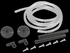
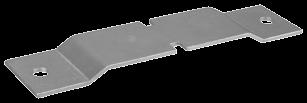


235 Accessories for heating technology / air conditioning technology / industrial applications and sensors FS-H FS2-H JZ-04 JZ-05 / 6 K JZ-05 / 6 M JZ-06 / 1 JZ-07 JZ-08 JZ-09 JZ-10 JZ-17 JZ-18 Z-20-1 JZ-24 Catalogue 2015 Page 235 Accessories / miscellaneous
236 Type comparison old/new (JAT, JET and JRT) Old alre types Control range Switching difference New alre types Control range Switching difference JAT-1; JAT C 2 20 K JAT C 2 20 K JAT-1F; JAT-6F C 2 20 K JAT-110F C 2 20 K JAT-112 * C FT JAT C 2 20 K JAT-120F 0 60 C 2 20 K JAT-2N; JAT-7N C 2 20 K JAT C 2 20 K JAT-2NF; JAT-7NF C 2 20 K JAT-130F C 2 20 K JAT-3; JAT-5N C 3 16 K phased out alternative WR JAT-5NF C 3 16 K phased out alternative WR JAT C ST phased out JAT C 9 50 K phased out JET-4X; JRT-8X; C 2 20 K JET-5X; JRT-5X C 1 K fixed JET-110X C 2 20 K JRT-8X(N) C 2 20 K phased out JET-4XG; JRT-5XG C 2 20 K phased out JET-4XF; JRT-8XF; C 2 20 K JET-5XF; JRT-5XF C 1 K fixed JET-110XF C 2 20 K JET-5XFG; JRT-5XFG C 1 K fixed JET-110XFG C 2 20 K JRT-7X C FT JET-112X C FT JRT-7XG C FT phased out JRT-7XF C FT JET-112XF C FT JET-7X; JRT-11X; 0 60 C 2 20 K JET-8X; JRT-9X 0 60 C 1 K fixed JET-120X 0 60 C 2 20 K JET-7XG; JRT-11XG 0 60 C 2 20 K JET-120XG 0 60 C 2 20 K JET-7XF; JRT-11XF; 0 60 C 2 20 K JET-8XF; JRT-9XF 0 60 C 1 K fixed JET-120XF 0 60 C 2 20 K JET-7XFG; JRT-9XG 0 60 C div. phased out JET-16XN; C 2 20 K JET-17XN; JRT-14XN C 1 K fixed JET-130X C 2 20 K JET-16XNG; JRT-14XG C div. JET-130XG C 2 20 K JET-16XNF; C 2 20 K JET-17XNF; JRT-14XNF C 1 K fixed JET-130XF C 2 20 K JET-18XN; JRT-17XN C ST JET-133X C ST JET-18XNF C ST JET-133XF C ST JET-10X; JRT-12XN; C 2 20 K JET-140X C 2 20 K JET-140XF C 2 20 K JET-12X; JRT-16X; C ST JET-143X C ST JET-12XF C ST JET-143XF C ST JET-13; JRT-13A C 8 50 K JET C 8 50 K JET-13F C 8 50 K JET-150F C 8 50 K JET C ST JET C ST JET-153F C ST JET-20N; JRT-21N; C 2 15 K JET-21N; JRT-20N; C 1 K fixed JET-22; JRT C 2 15 K JET-23; JRT C 1 K fixed JET-110R C 2 20 K JET-20NF; C 2 15 K JET-21NF; JRT-20NF C 1 K fixed JET-22F; JRT-26F C 2 15 K JET-23F; JRT-22F C 1 K fixed JET-110RF C 2 20 K JET-24; JRT-27; C 2 15 K JET-25; JRT C 1 K fixed JET-120R 0 60 C 2 20 K JET-24F; JRT-27F C 2 15 K JET-26F; C 2 15 K JET-25F; JRT-24F C 1 K fixed JET-120RF 0 60 C 2 20 K JRT-27FH C 3 K fixed * Will be discontinued Catalogue 2015 Page 236
237 Tips for heating installers and electricians Berlin 1000 / 2000 / 3000 bimetal Problem Large temperature variation present in the room (approx. 5 8 K). The setting knob (setpoint transmitter) must be set higher than the desired room temperature. Cause 1.) The neutral conductor N is not connected to terminal 4 of the controller. 2.) The neutral conductor N is connected to terminal 4 of the controller, but not in the distribution system (distribution box, fuse box). 1.) ncoming and outgoing (switched) phase have been interchanged. As a result, the feedback resistor continuously carries a voltage and acts like a temperature reducer in the room. Moreover, the temperature variation is very high (approx. 5 8 K) 2.) The heating output is dimensioned too low for the room. As a result of this, the power-on time of the controller is too long; the feedback resistor is thus switched on for too long and acts as a temperature reducer in the room. 3.) External heat sources are influencing the controller (for example, the sun, TV, lamp etc.). These external heat sources cause the controller to register a higher-than-actual temperature and, as a result, the room is not heated sufficiently. The setting knob (setpoint transmitter) must be set lower than the desired room temperature. The room does not become warm. 1.) The controller has been installed, for example, behind a curtain or on an outer wall or next to a door. The controller registers a lower-than-actual temperature and, as a result, the room is overheated. 1.) Faulty actuator element, actuator element does not open the valve. 2.) There may be coarse construction site dirt in the controller. This dirt is preventing the contact from closing. 3.) The controllers of two rooms have been connected in series. These rooms only become warm when both controller contacts are closed. Other notes: 1.) Particularly with floor heating, it is important to remember that there are very long reaction times. Therefore, the room heats up very slowly and also cools slowly (incident sunlight, for example, results in overheating). Therefore, do not expect that a cold room will reach the desired room temperature within a short time after having set the adjusting knob to a high value. 2.) Also, with well insulated rooms, remember that the room temperature drops very slowly. As a result, it can happen that at night, despite Reduced operation (for example, 4 K lower), the room temperature drops only a little and the heating therefore does not get activated for a prolonged time. 3.) Very often, the function of bimetal controllers is impaired or rendered completely useless by construction site dirt that has penetrated into them. Therefore, the controllers should be installed only after any required spatula, painting or wallpapering work. Avoid drilling dust without fail. ndustrial technology Note for connecting industrial thermostats and controllers to PLC or DDC: For connecting industrial thermostats and controllers to programmable logic controllers (PLC) or direct digital controls (DDC), the use of normal commercial coupling relays with 230 V~ coil voltage and gold-plated switching contacts is recommended. Catalogue 2015 Page 237 Accessories / miscellaneous


238 Catalogue 2015 Page 238 Sensor characteristic curves table of sensor values LM 235 Z mvolt N 1000 TK 5000 Ω N 1000 Ω PT 1000 Ω PT 100 Ω Temperature C
HERZ Electronic room thermostat analog and digital
 Dimension in mm 3 F799 11-3 F799 14 HERZ Electronic room thermostat analog and digital Data sheet for F799, Issue 0317 3 F799 15 3 F799 18 Mounting plate Page 1 Technical data 3 F799 11-14 3 F799 15-18
Control Solutions Biofloor
 MCF234 Distributor for Wired Control System COMAP proposes a new control system for heating and cooling underfloor. Consisting of a 6 or 10- channels controller (MCF234), analogic (TAF234) or electronic
Technical Data Electric double-motor-actuators
 M768 Electric double-motor-actuators Contents Page General data Overview, application, design and mode of operation, mounting position Technical details General Motors Switching and signaling unit Electrical
Application technology, 5th edition. Volume III: Fonterra radiant heating and cooling
 Application technology, 5th edition Volume III: Fonterra radiant heating and cooling Regulation components, manifolds and manifold cabinets Regulation components, manifolds and manifold cabinets System
Control solutions Biofloor
 ACTUONOFF Actuator ON/OFF Normally Closed for valves and manifolds Application Actuation of common valves, for example Comap thermostatic valves for radiators, Ballorex Dynamic valves and underfloor heating
Special voltages: Voltage >500 V AC are only permissible with external control box. 3-phase AC Voltages/frequencies. 1-phase AC Voltages/frequencies
 General information Actuator controls AC 01.2 for controlling multi-turn actuators of the SA/SAR type range and part-turn actuators of the SQ/SQR.2 type range. Power supply Standard voltages AC: 3-phase
ELECTRONIC THERMOSTAT: T901
 μnistδt ELECTONIC THEMOSTAT: T One contact output DESCIPTION The T series proportional thermostats are microcomputer based, proportional and integral (PI) devices with one contact time proportioning output.
We reserve the right to alter data according to improvements made. Previous documents become invalid with the issue of this document.
 General information Actuator controls AC 01.2 for controlling multi-turn actuators of the SA/SAR type range and part-turn actuators of the SQ/SQR.2 type range. Features and functions Power supply Standard
High-efficiency Drinking Water Pump. Rio-Eco Therm N. Type Series Booklet
 High-efficiency Drinking Water Pump Rio-Eco Therm N Type Series Booklet Legal information/copyright Type Series Booklet Rio-Eco Therm N All rights reserved. The contents provided herein must neither be
Power consumption In operation At rest For wire sizing. Connection Motor. Auxiliary switch
 echnical data sheet SF24G-S-S2- Modulating spring return actuator with emergency function in the IP66 protective protecti e housing for adjusting air dampers in industrial plants and in technical building
Remote Temperature Controllers. Quick Selection Guide
 Remote Temperature Controllers Quick Selection Guide A Complete Selection For A Wide Range Of Applications Electronic Standalone Controllers T775 Provide on/off, modulating, or reset control in applications
1 potential-free change-over contact (max. 24 V DC/1 A) for SIL collective failure signal SIL functions - safety functions Standard: Safe ESD
 for SIL collective failure signal SIL functions - safety functions Standard: Safe ESD") General information AC 01.2 Actuator controls in SIL version for controlling multi-turn actuators of the SA/SAR.2 type range and part-turn actuators of the SQ/SQR.2 type range. Information on SIL features
General information AC 01.2 Actuator controls in SIL version for controlling multi-turn actuators of the SA/SAR.2 type range and part-turn actuators of the SQ/SQR.2 type range. Information on SIL features
ambiente wood burning stoves
 ambiente wood burning stoves Are you looking for a stove with an individual character? Then the ambiente range by Spartherm is just what you need. The ambiente line combines simple, timeless design with
OPERATING INSTRUCTIONS
 Emergency Cord Switch Type PRS Device identification No.: 91.054 033.001, /.101 and /.201 OPERATING INSTRUCTIONS 2 CE Sign and Conformity The device meets the requirements of the valid European and national
Power consumption In operation At rest For wire sizing
 echnical data sheet SF24G-S- Modulating spring return actuator with emergency function in the IP66 protective protecti e housing for adjusting air dampers in industrial plants and in technical building
Cooling mode. Temperature adjustment button. Override button. 24 VAC COM AN1 COM OPEN CLOSED T2/AN2 T2/COM T3 T3 COM SENSOR COM C-Over COM NSB
 TB6980/TB7980 1. Introduction The TB6980/TB7980 digital thermostats provide proportional plus integral individual space temperature control in zoned commercial HVAC systems such as hydronic and pressure
Smart balancing system Series SB Main features
 Smart balancing system Series SB Main features Control system for radiant heating Innovative solution for auto-dynamic balancing Easy installation and start-up Dynamic adjustment to the operating point
S840, S845, S846 Series Single-break changeover, NC or NO contacts, positive opening operation and wiping action Catalogue D40.en
 Snap-action switches S80, S85, S86 Series Single-break changeover, NC or NO contacts, positive opening operation and wiping action Catalogue D0.en Snap-action switches, S80, S85, S86 Series Single-break
Premounted Midi Shunts
 Application Midi Shunt 088U0181 - with one circuit Midi Shunt 088U0182 - with two circuits Midi Shunt 088U0183 - with three circuits The Danfoss floor heating midi shunt is a series of pre-mounted shunts
Condensation monitor
 QXA2101 QXA2100 Condensation monitor QXA2100 QXA2101 Monitor to prevent damage caused by condensation on chilled ceilings and HVAC plants with AC/DC 24 V power. Can also be used with extension module AQX2000
VALVE CONTROLLERS Controllers for Dust Extr 2010 / 2011 action Technology
 VALVE CONTROLLERS Controllers for Dust Extraction 2010 Technology / 2011 Valve controllers for all cases HESCH has the skills and technology to tackle any control task for dedusting of filter and dust
DCT 533. Industrial Pressure Transmitter with IO-Link Interface. Stainless Steel Sensor
 DCT 5 Industrial Pressure Transmitter with IO-Link Interface Stainless Steel Sensor accuracy according to IEC 60770: standart: ± 0.5 % FSO sption: ± 0.5 % FSO Nominal pressure from 0... 00 mbar up to 0...
Product features & Overview. KA Linear actuators
 Product features & Overview Linear actuators 66 Linear actuators Linear actuator Product features Wide range of force outputs Solid metal housing Large stroke range Maintenance-free gearbox Wide range
Outdoor system solutions
 Outdoor system solutions 2 The whole is more than the sum of its parts The same is true of Rittal The System. With this in mind, we have bundled our innovative enclosure, power distribution, climate control
DELTA i-system 11/1 1/1. 1/6 Introduction. 1/7 Switches and pushbuttons. 1/12 Outlets. 1/17 International plug-and-socket devices
 DELTA i-system 1 1/6 Introduction 1/7 Switches and pushbuttons 1/12 Outlets 1/17 International plug-and-socket devices 1/18 Lighting control 1/21 Motion detectors 1/23 Shutter/blind control 1/28 Room temperature
Polygyr -Compact Exhaust Air Temperature Controller
 Document No. CM1N3405E-P25 Polygyr -Compact Exhaust Air Temperature Controller Features Two outputs for heating and cooling Continuous control signal Application P control Electronic 24 Vac The RCM61.21
DELTA i-system. 1/6 Introduction. 1/7 Switches and pushbuttons. 1/13 Shutter/blind controls. 1/19 Socket outlets
 1 1/6 Introduction 1/7 Switches and pushbuttons 1/13 Shutter/blind controls 1/19 Socket outlets 1/25 International plug-and-socket devices 1/26 Lighting controls 1/29 Motion detectors 1/31 Room temperature
JUMO MIDAS Pressure transmitter
 Phone: +44 19 635533 Fax: +44 19 6356 Data Sheet 401001 Page 1/5 JUMO MIDAS Pressure transmitter Brief description Pressure transmitters are used for measuring the relative (gauge) pressure in liquids
PRODUCT CATALOGUE. 24-Volt DC valve actuators for spindle valves, pressure reducers, ball valves and butterfly valves
 PRODUCT CATALOGUE 24-Volt DC valve actuators for spindle valves, pressure reducers, ball valves and butterfly valves Innovative and user-friendly Simplest form of actuation through integrated motor controls
ELECTRIC POWER REGULATION TEMPERATURE CONTROLLERS. room C
 ELECTRIC POWER REGULATION STS converts 0 10 V signal to one time proportional and up to 3 contact. Each step must be identical in power. input output 1 2- number of steps 2 Vac, 1 VA 0 10 Vdc < 1 ma for
Description. functions including single duct pressure dependent or pressure independent systems.
 Description The Meridian Basic control system converts a single zone HVAC unit into a variable air volume/variable air temperature multiple zone system. The microprocessor based Zone Manager calculates
4 Specification Magneta Smedegaard twin pumps
 4 Specification Magneta Smedegaard twin pumps 4.1 Variable Speed Circulator Pumps Designation: Example Magneta Smedegaard 30-60D Key to the designation Main applications Heating, ventilation, air-conditioning,
Application Support. Product Information. Omron STI. Support Engineers are available at our USA headquarters from
 Omron STI Application Support Thank you for your interest in Omron STI products. Please contact Omron STI with your application questions. Support Engineers are available at our USA headquarters from 4:00
Rittal TopTherm Filter Fans
 Rittal TopTherm Filter Fans More pressure. Higher air flow rates. 2 Installation without tools Snap-in mounting for easy installation Simple reversal of the air flow direction by turning the fan module
MiG2 TIME SWITCHES. 1, 2 & 4 Channel, 365 Day, Energy Saving Time Switches
 MiG2 TIME SWITCHES 1, 2 & 4 Channel, 365 Day, Energy Saving Time Switches The MiG2 series of timers are programmable 365-day time-switches, incorporating: Multiple switching times per day Single and block
GRIDCON ACF ESS GREAT COMBINATION ACTIVE FILTER AND ENERGY STORAGE.
 GRIDCON ACF ESS GREAT COMBINATION ACTIVE FILTER AND ENERGY STORAGE. WWW.REINHAUSEN.COM SAMSUNG ESS INSIDE 1 GRIDCON ACF ESS 2 ENERGY STORAGE SYSTEMS IMPROVE FLEXIBILITY. Energy storage systems are an attractive
ANKERSMID Temperature controller ATC 510/520/525 for wall-mounting. Application
 2-3.1 ATC 510/520/525 for wall-mounting Application The ATC 510/5205/525 is a modern microprocessor-based (PID) control device featuring easy handling and a digital display. The clear design of the operator
ELIOS 25 DIGITAL CONTROL UNIT WITH LCD DISPLAY FOR THERMAL SOLAR SYSTEMS TDS 006 M00 0SE A
 ELIOS 25 DIGITAL CONTROL UNIT WITH LCD DISPLAY FOR THERMAL SOLAR SYSTEMS TDS 006 M00 0SE 012945A0 040906 1 MAIN FEATURES Power supply 230V~ ±10% 50Hz Backlit alphanumeric LCD display Management of 5 output
Boiler Management Unit (BMU)
") 7 495 Boiler Management Unit (BMU) LMU74... LMU75... LMU7 are digital Boiler Management Units (BMUs) for use in gas-fired appliances equipped with premixing burners. LMU74 without combustion optimization
7 495 Boiler Management Unit (BMU) LMU74... LMU75... LMU7 are digital Boiler Management Units (BMUs) for use in gas-fired appliances equipped with premixing burners. LMU74 without combustion optimization
3 Specification Magneta Smedegaard
 3 Specification Magneta Smedegaard 3.1 Variable Speed Circulator Pumps Main applications Heating, ventilation, air-conditioning, refrigerating and circulation systems - One-pipe and two-pipe systems -
Model WEP Electro-pneumatic positioner. WEP positioner A valve control without compromise
 Data Sheet DS/WEP-EN Rev. C Model WEP Electro-pneumatic positioner WEP positioner A valve control without compromise Standard - ma input Single acting, force-balance operating principle Excellent dynamic
EL5600 Series Electric Actuators for DN15 to DN100 Valves
 Page 1 of 5 TI-P358-07 CH Issue 8 Cert. No. LRQ 0963008 ISO 9001 EL5600 Series Electric s for DN15 to DN100 Valves Description The EL5600 series electric actuators are reversible having linear output.
Installation Guide. ECL Comfort 210 / 310, application A231 / A Table of Contents
 1.0 Table of Contents 1.0 Table of Contents... 1 1.1 Important safety and product information..................... 2 2.0 Installation... 4 2.1 Before you start.....................................................
ST48-WHUV.102. Wiring diagram. Product description. PID controller. Order number
 ST48-WHUV.12 PID controller Order number 935.15 Wiring diagram Product description This micro-processed controller serves for temperature control at high measuring accuracy. Beside resistance sensors and
Overview of types. Technical data
 Technical data sheet 6..S+NVFT24-MFT-E Globe valves, 2-way, with flange PN 16, actuator with emergency control function for closed hot water systems up to 150 C in district heating applications approved
Premounted Midi Shunts
 Application Midi Shunt 088U0181 - with one circuit Midi Shunt 088U0182 - with two circuits Midi Shunt 088U0183 - with three circuits The Danfoss floor heating midi shunt is a series of pre-mounted shunts
Digital ph transmitter
 Digital ph transmitter Compact, remote versions for DN 15 to 200 Fully programmable ph transmitter functions for all kinds of ph-measurement tasks Large range of process connections with various fittings
Minimum 27 in-lb torque
 LU Series Actuator Minimum 27 in-lb torque For damper areas up to 6.8 sq-ft* All Actuators have BDCM LU Series - At A Glance LUB(X)24-3 (p. 258) LUB(X)24-SR (p. 260) LUX24-MFT (p. 262) Basic Product Flexible
AQUASTAR C6. (Comfort 6000) Next Generation Auto Backwash Valve System. (selectable time-pressure or remote cycle start)
 Next Generation Auto Backwash Valve System. (selectable time-pressure or remote cycle start)") AQUASTAR C6 (Comfort 6000) Next Generation Auto Backwash Valve System (selectable time-pressure or remote cycle start) SIDE MOUNTED AND TOP MOUNTED VALVES WITH QUICK INSTALL ELECTRIC ACTUATORS FOR PIPE
AQUASTAR C6 (Comfort 6000) Next Generation Auto Backwash Valve System (selectable time-pressure or remote cycle start) SIDE MOUNTED AND TOP MOUNTED VALVES WITH QUICK INSTALL ELECTRIC ACTUATORS FOR PIPE
and other modular devices for low voltage installation
 Technical catalogue System and other modular devices for low voltage installation 2CSC400002D0204 SUMMARY Introduction Miniature Circuit-Breakers Residual Current Devices Auxiliary elements and accessories
Manual for Inverter system type PCI05
 - 1- Manual for Inverter system type PCI05 SAFETY INSTRUCTIONS This manual must be read before installation, use or work on the product. This product contains dangerous voltages that when touched can cause
Electric Actuator Options & Accessories
 The basic options and accessories listed in this section represent many of the most commonly used for electric actuation, factory configured to order on the actuation package. Contact Spears for any desired
LF Series At A Glance
 LF Series Spring Return Direct Coupled Actuator Minimum 35 in-lb Torque For damper areas up to 8 sq-ft* Applications Cost effective quality and performance for a range of applications including: Classroom
Linear actuator. Product features. Overview. Wide range of force outputs. Wide selection of column adapters. Wide selection of flanges
 V Linear actuator Product features Wide range of force outputs Wide selection of column adapters Large stroke range Wide selection of flanges Constant positioning times under fluctuating loads Solid metal
SP-32 & SP-32D SP-33, SP-33D SP-34, SP-34D. Description. Specifications. Single Stage Temperature Control
 SP-32, SP-32D SP-33, SP-33D SP-34, SP-34D Single Stage Temperature Control Description The SP-3x and SP-3xD series of controls are single stage, general purpose, temperature controls with wide application
lindab comfort Regula Control er
 lindab comfort Regula Controller Regula Controller Control equipment for waterborne cooling and heating systems. Use Regula Mono, Duo and Regula Lon control the cooling and heating of a room in sequence
Electronic Circuit Breaker ESS20-0..
 Electronic Circuit Breaker ES-0.. Description Electronic circuit breaker type ES-0.. is designed to ensure selective disconnection of individual loads in systems which are powered by a DC 4 V switch-mode
EAS822 (Contrac) Power Electronic Unit
 Power Electronic Unit") Contents Data Sheet Rev. A EAS822 (Contrac) Power Electronic Unit For continuous control of Contrac actuators PME120 AN and LME620 AN Microprocessor-controlled power electronic unit with integrated frequency
Contents Data Sheet Rev. A EAS822 (Contrac) Power Electronic Unit For continuous control of Contrac actuators PME120 AN and LME620 AN Microprocessor-controlled power electronic unit with integrated frequency
Electronic Ballast EVG 2000-T
 Electronic Ballast EVG 2000-T Operating Manual Table of contents 1 Description 1.1 Advantages of this ballast... 3 1.2 Functional principle... 3 1.3 Energization... 4 1.4 Visualization... 5 1.5 Indications
THR1 THR2 THR3 THV1 THV2 THV3
 Thermostats THV THR THERMOSTATS Compact Thermostat for DIN 35 mm. rail mounting. Based on bimetallic junction, provides high capacity NO or NC contact. Two versions available: THVx NO Contact Typically
Current Automation Catalogue
 Current Automation Catalogue Page 1 Visit our website for more indebt info on this product range Current Automation Catalogue Page 2 STECA Steca Solar Charge Controllers Steca Solar Charge Controllers
NEW. Wall controls. YFCN Fan Coil Units. Technical Guide - for internal distribution only
 NEW Wall controls Fan Coil Units www.euroventcertification.com www.certiflash.com Technical Guide for internal distribution only CONTENTS Construction Page 4 s Page 5 Dimension, Weight, Water content Page
Electrical data Nominal voltage AC 24 V, 50/60 Hz DC 24 V
 echnical data sheet SH24A-SR.. Modulating linear actuators for adjusting air dampers and slide valves in ventilation and air conditioning systems in buildings For air dampers up to approx. 3 m 2 Actuating
Data sheet. CI-TI TM Contactors and Motor Starters Circuit Breakers CTI B1427
 Data sheet CI-TI TM Contactors and Motor Starters Circuit Breakers November 2002 DKACT.PD.C00.L2.02 520B1427 Introduction Circuit breakers/manual motor starters cover the power ranges 0.09-12.5 kw This
Contact Dial Thermometer
 Data sheet 608523 Page 1/8 Contact Dial Thermometer Special features Class 1.5 Display range -40 C to +600 C Temperature controller with actual value display as built-in or add-on device in the stainless
SUCO Product Overview
 SUCO Product Overview Pressure Monitoring & an overview Mechanical Pressure Switches Electronic Pressure Sensors www.suco.de Mechanical Pressure Switches Pressure Switches with integrated connectors NO
See «Overview of types» 90 s / 60 mm 150 s / 100 mm Manual triggering of the adaption by pressing the «Adaption» button or with the PC-Tool
 echnical data sheet LHA-MF.. Multifunctional linear actuators for adjusting air dampers and slide valves in ventilation and air-conditioning systems for building services installations For air control
LF Series Spring Return Direct Coupled Actuator
 LF Series Spring Return Direct Coupled Actuator Minimum in-lb torque LF actuator For damper areas up to 8 sq-ft* Applications Cost effective quality and performance for a range of applications including:
Frost protection for pipes. 16 Technical handbook. Thermostat with line or ambient temperature sensor
 Frozen pipes can be a costly problem. When pipes are exposed to subzero temperatures they can burst, leading to considerable damage and disruption. The Raychem frost protection system provides an efficient
Function Relays, Interfaces and Converters
 Function Relays, Interfaces and Converters Interface Relays Narrow Design 3TX70 interface relays 3TX701 Interface relay, plug-in Plug-in socket interface, complete with relay Contact Rated control Width
Salt Spray Chamber HKT 1000
 Salt Spray Chamber HKT 1000 Corrosion testing system to carry out atmospheric corrosion tests according to the following test specification: DIN EN ISO 9227 (DIN 50 021) NSS, AASS, CASS test DIN EN 60068-2-11
DeltaSol AX. RESOL DeltaSol AX * * Mounting Connection Operation Application examples. manual
 RESOL DeltaSol AX Mounting Connection Operation Application examples DeltaSol AX *48000250* 48000250 Thank you for buying a RESOL product. Please read this manual carefully in order to put this controller
INDUSTRIAL THERMAL MANAGEMENT. Filter fans FL-Series
 Filter fans FL-Series Heating, cooling, climate, electrical power control. Since more than sixty years. DBK s knowledge of thermal management gives us the experience to guide and support you with your
JUMO ecotrans Lf 01/02
 Data Sheet 07 Page /7 JUMO ecotrans Lf 0/0 Microprocessor Transmitter/Switching Device for Conductivity Housing for DIN rail mounting (5 mm 7.5 mm to EN 075 A.) Brief description The JUMO ecotrans Lf 0/0
V200 V200. Control on water, proportional integral. Simplified Master / Slave operation GENERAL DESCRIPTION
 Master Slave 1 Slave (n + 1) Master Slave 1 Slave (n + 1) Simplified Master / Slave operation GENERAL is a CIAT electronic control system designed to control non-independent air conditioning terminal units
ACCESSORIES FOR SZE2 CABINETS
 ZPAS 143 DOORS Doors Intended for use instead of front solid door or rear panel. Maximum door opening angle: 120 Sheet steel textured powder paint, light grey (RAL 7035), stiffened profiles, brown smoked
Linear Valve Electric Actuator
 Linear Valve Electric Actuator www.powervalves.nl Company Profile Company Profile Sun Yeh Electrical Ind. Co., Ltd. was founded in 1986. We always strive for technical excellence, innovation and the highest
Digital ph transmitter
 Digital ph transmitter Compact, remote versions for DN 15 to 200 Fully programmable ph transmitter functions for all kinds of ph-measurement tasks Large range of process connections with various fittings
Creda Aluminium Radiator
 Creda Aluminium Radiator The radiator that s always at the right temperature, at the right time. As part of the Glen Dimplex range, the new Creda Aluminium Radiator has been designed and developed by our
INSTALLATION INSTRUCTIONS
 INSTALLATION INSTRUCTIONS TEC20 TEC20H ELECTRONIC CONTROLLER BARD MANUFACTURING COMPANY Bryan, Ohio 43506 Since 1914...Moving ahead, just as planned. Manual: 2100-306D Supersedes: 2100-306C File: Volume
TZIM. Electropneumatic Analog Positioner 10/ EN
 TZIM Electropneumatic Analog Positioner EP001XA.tif Q Convenient, simple design Q Easy to handle Q User-friendly operation, easy to understand Q Reliable concept, I/P conversion through the 500,000 times
To ensure proper installation, digital pictures with contact information to before startup.
 Check List for Optimal Filter Performance [ ] There should be no back-pressure on the flush line. A 1 valve should have a 2 waste line, and 2 valve should have a 3 waste line. Do not use rubber hosing
Pack Cat.Nos Switches16A-250VA. 1 gang - standard switches One-way switch Two-way switch Intermediate switch
 switches, automatic switches 7 758 06 Aluminium finish 7 758 20 Aluminium finish 7 758 05 Aluminium finish 7 756 55 Pearl finish 7 756 57 Aluminium finish To be equipped with cover plates (p. 475 to 481)
TeSys contactors. Use in category DC-1 (resistive loads; time constant L/R y 1 ms) Rated operational current Ie. to be wired in series
 Rated operational current Ie. to be wired in series") Selection 3-pole shockproof contactors FG d.c. supply Selection guide for utilisation categories DC-1 to DC-5 Use in category DC-1 (resistive loads; time constant L/R y 1 ms) Rated operational current
Selection 3-pole shockproof contactors FG d.c. supply Selection guide for utilisation categories DC-1 to DC-5 Use in category DC-1 (resistive loads; time constant L/R y 1 ms) Rated operational current
STRA-24 for chilled beams
 STRA- Installation and commissioning manual STRA- for chilled beams STRA- is the room controller for the pressure independent (Pi) and constant air volume chilled beams. It is possible to set different
Lenntech. Calio S. Type Series Booklet. High-efficiency Circulator Pump. Tel Fax.
 Lenntech info@lenntech.com Tel. +--6-9 www.lenntech.com Fax. +--66-89 High-efficiency Circulator Pump Type Series Booklet Legal information/copyright Type Series Booklet All rights reserved. The contents
ecotrans Lf 01/02 Microprocessor Transmitter / Switching Device for Conductivity
 Data Sheet 20.27 Page / ecotrans Lf 0/02 Microprocessor Transmitter / Switching Device for Conductivity Type 2027 Housing for DIN rail mounting (5 x 7.5 mm to EN 0 75 A.) Brief description The JUMO ecotrans
Belt Conveyor Pull Rope Switch Types HEN, HEK and SEM OPERATING INSTRUCTIONS
 Belt Conveyor Pull Rope Switch Types HEN, HEK and SEM OPERATING INSTRUCTIONS 2 CE-Sign and Conformity The device meets the requirements of the valid European and national regulations. Conformity has been
SPEED-CONTROLLED SCREW COMPRESSORS Volumetric flow rate: m 3 /min acfm
 www.almig.de SPEED-CONTROLLED SCREW COMPRESSORS Volumetric flow rate: 1.09 56.60 m 3 /min 38 2024 acfm 2 INTELLIGENTE DRUCKLUFT MADE IN GERMANY ALMiG Kompressoren GmbH A name that guarantees top-grade
Cert. n 0545 Carisma CRC Fan Coil Unit The Ultra Quiet Fan Coil TECHNICAL GUIDE
 Cert. n 0545 www.euroventcertification.com Carisma Fan Coil Unit The Ultra Quiet Fan Coil TECHNCAL GUDE Carisma CONTENTS Construction Page 4 s Page 5 Dimension, Weight, Water content Page 6 EUROENT certification
4 x 0-10Vdc Channels Fused 24V o/p terminals for actuator power Direct or buffered output signals
 IO Input/Output Modules IO-ABM4 Analogue Override Module Description IO-ABM4 Analogue Override Module Intended for applications which require independent manual override of analogue output channels from
InBin-P Pressure switches 5 Pa Pa
 InBin-P Pressure switches 5 Pa... 5.000 Pa Electrical binary pressure / differential pressure switches 5 Pa...100 Pa with adjustable switch activation delay 24 VAC/DC supply voltage, potential free switching
Command, control and regulation
 186 CONTROL SYSTEMS Command, control and regulation Mechanical regulators... 188 NO-NC thermostats... 191 Twin thermostats... 192 Change-over thermostats... 193 Hygrostats... 194 Flashing signal device...
EPS/ELA-Series User Manual EPS/ELA 250W
 EPS/ELA-Series User Manual EPS/ELA 250W EPS Stromversorgung GmbH Tel: +49 (0)821 570451 0 Index 3 Page: 1 Table of contents: Page 1. Features of ELA-Series... 3 1.1 Basic Functions... 3 1.2 Options...
Open Chassis Star-Delta Starter User Guide
 Open Chassis Star-Delta Starter User Guide (7.5kW~90kW) V2.0.1 Contents 1 Safety information... 1 2 Technical Data... 2 3 Supply & Motor Connections & Circuit Diagrams... 5 4 Control Connections & Operation...
Electrical data Nominal voltage AC/DC 24V Nominal voltage frequency 50/60Hz
 GR24A-5 / -7 GR24A-5 Rotary actuator for rotary valves GR24A-7 Rotary actuator for rotary valves Nominal torque 40Nm Nominal voltage AC/DC 24V Control Open-close echnical data Electrical data Nominal voltage
SUCO Product Overview
 SUCO Product Overview Pressure Monitoring & an overview www.suco-tech.com Pressure Switches with integrated connectors NO / NC / Changeover IP67 (up to IP6K9K) Robust, compact design Various connector
ELECTRO HYDRAULIC THRUSTERS
 ELECTRO HYDRAULIC THRUSTERS THE ORIGINAL. BE SAE. TECHNICAL DATA.moving ahead. DESIGN, UNCTION AND ADVANTAGES PRESSURE STRAP PISTON ROD PROTECTIVE TUBE REDUNDANT DUST PROTECTION SEAL PISTON ROD OIL ILLER
Temperature controls, Type RT
 MAKING MODERN LIVING POSSIBLE Technical brochure Temperature controls, Type RT RT temperature controls incorporate a temperature controlled, single-pole changeover switch where the contact position depends
Explosion and flame-proof cast iron electric motors
 Explosion and flame-proof cast iron electric motors EEx-d, EEx-de, IIB, IIC II, 2G IP55 II, 2G&D IP66 T4, T5, T6 Frame size 56 to 160 3 phases Voltage 230/400 V 50Hz Voltage 265/460V 60Hz Types of mounting