KART TACH, LAP TIMER AND TEMPERATURE GAUGE.
|
|
|
- Frederick Carter
- 6 years ago
- Views:
Transcription

1 KART TACH, LAP TIMER AND TEMPERATURE GAUGE

2
3 Congratulations on your new MyChron4 purchase! MyChron4 is an innovative instrument for karts, representing a revolutionary step in the development of electronic instrumentation for karts. Please check periodically on or websites for the new MyChron4 Firmware and Software updates.

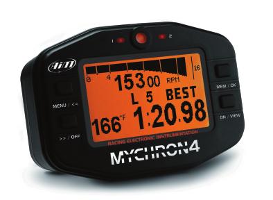
4 Your MyChron4 display show Led AL1 Temperature Alarm Led RPM bar graph Menù button Low Battery warning Switch-off button 1 Temperature with settable unit of measure Digital RPM Value

5 s the following information: RPM tattle Max RPM value and bar graph Data Recall Management and OK button Lap Number Switch-on and Quit button Lap Time
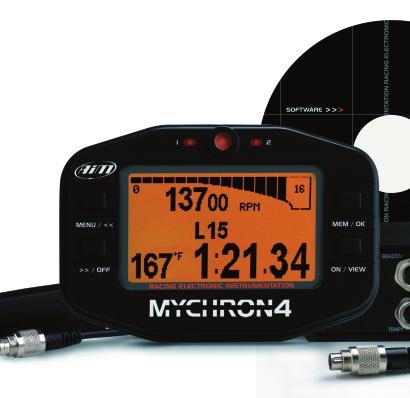
6 MY4 CONNECTIONS AND POWER Your MyChron4 is provided with three connectors in the back side: 1) Temperature Input You can connect an AIM sensor to measure Water Temperature, Exhaust Gas Temperature or Underspark Temperature. 2) Lap Receiver Input It can be both optical and magnetic. 3) MyChron4 E-Box/power/DataKey connection Connecting your DataKey to your logger you can collect all the recorded data and then download them to your PC. MyChron4 E-Box

7 RPM Connection 9V Internal batteries
8 MY4 TEMPERATURE SENSORS Underspark Thermoresistance Underspark Thermocouple These sensors measure the engine head temperature and are mounted to maintain the same compression ratio, eliminating the spark plug washer. Water Temperature Sensor
9 MY4 Water Temperature Sensor Holder The water sensor must be mounted on the sensor holder by winding the thread of the sensor with some Teflon, in order to guarantee a strong hold. Exhaust Gas Temperature Sensor For a correct measurement the Exhaust Gas Temperature sensor must be installed on the exhaust manifold at a distance of mm from the jacket piston.
10 MY4 LAP RECEIVERS As previously mentioned in the configuration menu, in case you should use a magnetic receiver on tracks provided with some magnetic bands, you must configure your MyChron4 to indicate: Magnetic Receiver The number of magnetic bands on the track The magnetic band corresponding to the finish line Optical Receiver
11 MY4 EXTERNAL POWER SUPPLY CABLE External Power supply cable The external power supply cable has a double function: not only it supplies energy to your MyChron4, using the engine start battery or the electric ignition, but also relevates the RPM value when connected to the ignition, with no need for a further RPM cable. It is generally used on 4-Stroke engines (i.e.honda, Briggs&Stratton).

12 MY4 INSTALLATION Please kindly pay attention to this phase for a correct use of your MyChron4. To lower the vibrations received by your logger, mount the rubber washer above and under the spoke of the steering wheel, as in the picture here below: Installation The RPM cable must be fixed on the spark plug cable according to the type of engine you have.


13 4 STROKE ENGINES 4-Stroke Engines (i.e. Honda, Briggs & Stratton) 4-Stroke engines are provided with a weak ignition system. To make the instrument receive more signals you should wind the thread around the spark plug cable, as in the picture here below: Winding around the spark plug cable in 4- Stroke engine applications Winding zoom

14 2 STROKE ENGINES 2-Stroke Engines (e.i. Tag, Junior, ICA, FA, ICC) In case of 2-Stroke engines, the ignition gives a very strong signal. Just lean the RPM thread onto the spark plug cable, fixing it with a clip as in the picture here below: Winding on spark plug cable for a 2 stroke engine Winding zoom
15
16 MY4 CONFIGURATION WIZARD You can enter the Configuration Menu pressing the MENU button. The Wizard automatically switches on everytime you enter the configuration menu, untill it s fully completed at least once. Following the Wizard steps, you need to configure: - Language - Driver s name - Drive Type (in case of gear transmission, please indicate the number of gears available) - Temperature Unit ( Fahrenheit Celsius) - Maximum RPM - RPM Tattle ( 0 = disabled) - Temperature Alarm - Hour / data The points listed here above are quite intuitive and do not need further explanations; nevertheless the type of transmission worths while spending some more words.
17 MY4 Direct Drive - Direct drive is exactly what it sounds like. There is no clutch, but rather a drive gear on the engine, straightly connected to a sprocket on the axle. It s typically applied to Formula A and ICA categories. Low Stall Clutch - If your clutch always remains engaged while racing, it can be considered a low stall clutch. Typical applications: Rotax Max, TAG, JICA, HPV, Comer, and most part of 4-Stroke engines (i.e. Briggs and Stratton, Honda, and others) Gearbox or manual transmission. In this case you are requested to insert on your display the gear number, i.e. 6 for a six speed transmission, 5 for a five speed, and 2 in case of RM1. You are asked to insert the gear number only if you select Gearbox as Drive Type. The gear number is displayed only when you install the MyChron4 E-Box.In case of Gearbox or Low Stall Clutch Drive types, the Predictive Lap Time function is not available.your configuration Wizard has now finished and your MyChron4 is ready to start running.
18 MY4 CONFIGURATION MENU The Configuration Menu can be activated pressing MENU button. Once you have completed the configuration Wizard at least once, the MENU screen appears as in the picture here below: Following the icons, you can activate some functions as follows:
19 MY4 BackLight Session Mode Min Lap Time Track Name Control Panel Wizard Hour Meter Language
20 MY4 CONFIGURATION MENU Backlight Backlight switch on/off Session Mode There are 2 session modes available: Lap Counter: the display shows the incremental lap number. Timed: Your MyChron4 can work as a countdown, showing you how long it will take you to get to the end of the race or qualifications. Min Lap Time This function sets the minimum predicted time between every lap signal and the following one. It s very useful to avoid the risk of recording false Lap Times, when there are more beacon transmitters installed along the track. From the start line and troughout all the Min Lap Time duration, the logger does not receive other signals.
21 MY4 Track Name The Track Name is associated with the every run recorded on your MyChron4. This is extremely useful when you have many runs, in order to understand when and where your data have been recorded. The Track Name is also managed by our RaceStudio2 Software, when you download your data on the PC. You can fill in the name of the tracks in which you normally race, and then select the current track among them Control panel This section will be analyzed subsequently in a separate chapter. Wizard Through this function you get back to to the beginning of the configuration, when the logger asks you again to go ahead with the configuration process as in the first time.
22 MY4 CONFIGURATION MENU Hour Meter Four different resettable counters (plus one, not resettable) are available, in order to keep under control the activity of your engines. Language selection It is possible to select one among the following languages: English, Spanish, French, German, Dutch, Swedish and Japanese.

23 MY4 CONTROL PANEL Selecting the Control Panel Icon, you enter a new menu: You can sets the icon as follows:
24 MY4 CONTROL PANEL Set RPM parameters Temperature Setup Drive Setup Split setup System Setup Enter Driver s Name Eliminate Data
25 MY4 RPM parameters The parameters used to improve the RPM management are: Maximum RPM It grants the best visualization of the RPM Scale. RPM factor For 2-Stroke and 4-Stroke engines with lost spark, please select the X1 factor. RPM Tattle It indicates the limit-level over which the RPM alarm led switches on. RPM Peak Hold The maximum RPM value is obtained at the very end of a straight line, just before the turn. At that point the driver cannot lower his eyes to read the gauge, since he has to face the corner. When you set the Hold RPM Peak ON, your MyChron4 will keep the RPM value
26 MY4 CONTROL PANEL fixed for some seconds, in order to give you the possibility to get the RPM Peak value after the corner itself. Temperature Setup This section allows to modify the following values: Temperature alarm It lights everytime the Temperature value goes higher than the limit-value set. Temperature Measure Units You are free to choose to get the Temperature in C or F scale Drive Setup As already seen in the Wizard this function concurs in eventually selecting the type of transmission and the number of gears from 2 to 6 Split Setup Number of magnetic bands This function allows to insert the number of
27 MY4 magnetic bands located along the whole track. Type of Split: You can choose to have an absolute Split value or get the Split as the difference between the current and the Best Lap. Finish band It allows to select the datum band to get the Total Lap Time System Setup Time/Date It allows to modify the following parameters: Predictive Lap Time It indicates the Predictive Lap Time automatically calculated by the logger when no splits are required and in case of direct-sproket engine (i.e. FA, ICA). You can choose between Absolute and Differential Predictive Lap Time.
28 MY4 CONTROL PANEL Reverse This function assets the visualization of the display in negative or positive mode. Driver s Name Once you have inserted the driver s name, MyChron4 associates it to every run recorded, both in the visualization on display and during the analysis of the downloaded data through RaceStudio2 Analysis Software. Clear data Function allowing the full reset of the acquired data.
29
30 MY4 DATA ANALYSIS Press the MEM/OK button after an on-track session to review the data. Session Summary, The first screen shows the Session Summary, as in the picture here beside. The Session Summary page displays information in two sections: the upper one, indicating the date of the test, the test number, the number of laps in the test, the maximum RPM value and the maximum Temperature value, and the lower one showing your three fastest lap times, max and min RPM, and max Temp for each lap. You can switch to previous or following sessions using the << and >> buttons.
31 MY4 Session number 1 Total laps of session 3 fastest laps Max and min RPM of laps max temperatur of lap
32 MY4 DATA ANALYSIS Lap Time Histogram Press MEM/OK again to switch to the Lap Time Histogram screen. This view shows a general summary of the main information of the current session, where each Lap Time is represented by a vertical bar. This view helps you quickly see trends in your kart setup, showing the test number, the lap number and the lap time across the top. The bottom always displays the Best Lap Time for the session and the differential +/- time from the Best Lap to the Lap visualized. You can scroll though the laps using the << left button, and the >> right button.

33 MY4 session 1 total 13 laps selected Lap Time Time difference between the selected Lap and the Best Lap
34 MY4 DATA ANALYSIS RPM values graph Pressing the MEM/OK key for the third time you pass on to the graphic page of the number of RPM, with the cursor already positioned on the previous RPM selected in the histogram graph, (please have a look at the screen shot here beside). Moving with the keys << and >>, you move the cursor to visualize the different Temperature values and the RPM s.
35 MY4 Progress of the number of RPM during the session Accurate value of the Temperature and RPM
36 MY4 DATA ANALYSIS Splits of the selected Lap Selecting again the MEM/OK key, you pass to the next screen where the provided data is a summarization of the laps that you were analyzing in the previous display. track name, date, hour Value of the RPM and maximum / minimum Temperature in laps Lap Time and Split Time
37 MY4 Best Rolling and Theoretical Best Lap Always using the MEM/OK key, if there are more Splits present on the track then you pass onto the last screen. A brief explanation is required for the two values of the display, as in the picture here below: The Best Rolling represents the actual real time the driver made in one lap but not from the finishing line to finishing line. The Theoretical Best is the time resulting from the total sum of the best Splits recorded in the session.
38 MY4 DATAKEY FOR DATA DOWNLOAD Optional to your MyChron4 you can have the MyChron4 DataKey, a useful and handy USB device, provided for a safe and quick data storage, together with the installation CD of RaceStudio2, the software properly developped by AIM to analyze data stored in your gauge. With your new MyChron4 you do not need a laptop on the track: you can download your data from your logger on to the optional DataKey, in order to move them, in a second time, to your PC. MyChron4 DataKey is provided with 32 Mb of not volatile memory. You can record on your DataKey

39 MY4 information received from different MyChron4s or got from different sessions made with the same kart. When you download the data to your PC, they will be properly managed, and splitted in different files. Every test will be associated to the driver s name and track name; time and date of the test are recorded too.
40 MY4 DATAKEY FOR DATA DOWNLOAD The same DataKey is to be used to download new updates of MyChron4 firmware. To download the data collected from your MyChron4 to the PC, please follow the steps listed here below: 1)Connect the DataKey USB connector to your MyChron4 2)The downolad process automatically starts, showing on MyChron4 display three possibilities: Memory empty: there are no data stored in your MyChron4 No new data: there no new information to be downloaded on your MyChron4 Download data 3)Connect your DataKey to the USB input on your PC 4)Start RaceStudio2 software and click on Download button 5)Among all the tests showed, flag just the ones to

41 MY4 be downloaded 6)Click on Download selected to activate the downloading process and eventually close clicking on Save button. To visualize and analyze the downloaded data, please click on Analysis button.

42 DATA DOWNLOADING MANAGEMENT The data downloading management window displays: - The folder where the files resulting from the download process are saved - The scheme of the files name
43 MY4 - The grid reporting the information about the tests stored on the DataKey, cronologically ordered. The runs already downloaded on the PC are automatically identified by a tick displayed in the Downloaded column, while the runs still stored on the DataKey are automatically selected (tick in the column Sel ) to be downloaded. The Choose folder button opens a browsing window to select the file destination The DRK file name button opens the window to compose the DRK file name
 and the whole list of the available elements (right")
44 DATA DOWNLOADING MANAGEMENT The window here above displays: - The DRK file name composition - The two lists reporting both the elements currently composing the drk file name (left one) and the whole list of the available elements (right one)
45 MY4 - Some further keys to be used to: Change the order of the elements selected to compose the file name; Eliminate an element from the name of the file; Add a selected element to the file name; Remove all the elements from the file name, to start a new composition of the same file name; Exit from the window saving the changes to the settings (OK button) Exit from the window without changing the settings (CANCEL button) The key, in the top right corner of the grid of runs in the Download Data window, leads to a new screen, available to personalize the same informa-

46 DATA DOWNLOADING MANAGEMENT tion showed in the grid and display the list of the visible columns in the same grid of runs. Clicking on the column header of the grid of runs, it s possible to reorder the number of runs displayed, according to the kind of information represented in the column. Clicking again the order gets inverted. Clicking on the same column header of the grid of runs with the right side of the mouse you can choose whether or not to remove the column (to restore the column display, use the configuration window of the grid, to be activated pressing.. key)
47 MY4 For further information, please check on or
48 Dealer AIM SRL Via Cavalcanti, Cernusco S.N.(Mi) Italia Tel Fax
EXPANSION BOX FOR MYCHRON4 SYSTEMS.
 EXPANSION BOX FOR MYCHRON4 SYSTEMS www.mychron4.com EXPANSION BOX FOR MYCHRON4 SYSTEMS MyChron4 ebox is the new instrument projected by AIM to enlarge further on the high performances of the innovative
FORMULA STEERING WHEEL User Manual
 FORMULA STEERING WHEEL User Manual Dear Formula steering wheel Owner, Your Formula steering wheel belongs to the latest generation of AIM dashes for car racing and provides you with a high tech and nice
User Guide My-Chron 2 Model MCT/K and MCV/K
 User Guide My-Chron 2 Model MCT/K and MCV/K Introduction Congratulations on your purchase of a My-Chron 2 from AIM, the world leader in motor sport electronics. The My-Chron 2 incorporates the most advanced
MXL Strada / Pista Plug and Play kit for Kawasaki ZX-10 R
 INSTALLATION DOCUMENTATION 1/03/2006 P&P KIT Installation procedure for MXL Strada / MXL Pista Kawasaki ZX6R-ZX6RR - 2003-2004-2005 kit Version 1.02 Kawasaki ZX10R 2003-2004-2005 MXL Strada / Pista Plug
MXL Pista / MXL Strada KIT FOR SUZUKI GSX R
 INSTALLATION DOCUMENTATION 1/03/2006 Bike KIT Installation Manual: MXL kit for Suzuki GSX-R K5-K6 Version 1.02 Suzuki GSX R K5-K6 750cc 1000cc MXL Pista / MXL Strada KIT FOR SUZUKI GSX R 2005-2006 The
Experiment P-16 Basic Electromagnetism
 1 Experiment P-16 Basic Electromagnetism Objectives To learn about electromagnets. To build an electromagnet with a nail, a wire and additional electrical elements. To investigate how the number of winds
Quick Guide. Unipro Laptimer Version September Go faster faster. UNIPRO ApS
 Quick Guide Unipro Laptimer 6003 Version 1.45 5. September 2009 Go faster faster UNIPRO ApS VIBORG HOVEDVEJ 24 DK-7100 VEJLE DENMARK Tel.: +45 75 85 11 82 Fax: +45 75 85 17 82 www.uniprolaptimer.com mail@uniprolaptimer.com
Quick Guide. Unipro Laptimer Version Go faster faster. UNIPRO ApS
 Quick Guide Unipro Laptimer 5004 Version 1.32 Go faster faster UNIPRO ApS VIBORG HOVEDVEJ 24 DK-7100 VEJLE DENMARK Tel.: +45 75 85 11 82 Fax: +45 75 85 17 82 www.uniprolaptimer.com mail@uniprolaptimer.com
Lingenfelter NCC-002 Nitrous Control Center Quick Setup Guide
 Introduction: Lingenfelter NCC-002 Nitrous Control Center Quick Setup Guide The NCC-002 is capable of controlling two stages of progressive nitrous and fuel. If the NCC-002 is configured only for nitrous,
MXL Pista / MXL Strada PLUG & PLAY KIT FOR SUZUKI GSX R
 INSTALLATION DOCUMENTATION 2/03/2006 P&P KIT Installation Manual: MXL P&P kit for Suzuki GSX-R- 2003-2004 Version 1.02 Suzuki GSX R 2003-2004 600 750 1000cc MXL Pista / MXL Strada PLUG & PLAY KIT FOR SUZUKI
EPAS Desktop Pro Software User Manual
 Software User Manual Issue 1.10 Contents 1 Introduction 4 1.1 What is EPAS Desktop Pro? 4 1.2 About This Manual 4 1.3 Typographical Conventions 5 1.4 Getting Technical Support 5 2 Getting Started 6 2.1
MXL Pro ON-TRACK SESSIONS OVERSTEERING AND UNDERSTEERING ANALYSIS. Vehicle: Car from IPS Championship Date: 05/20/2007 ENGINE ANALYSIS
 ON-TRACK SESSIONS System: MXL Pro + GPS Track: Adria (RO, Italy) Vehicle: Car from IPS Championship Date: 05/20/2007 ENGINE ANALYSIS Introduction To hold this test, we have been using the following sensors:
Digatron s DT-46K Instruction Manual
 Digatron s DT-46K Instruction Manual PLAY PAUSE MAX EVENT FUNCTION POWER EXIT Introduction Congratulations on the purchase of your new DT-46K. The DT-46K is Digatron s small, easy to use, multi-function,
With PRO+ Datalogger:- Lambda (Air/Fuel Ratio)* Turbo Boost* Brake Pressure Front & Rear +Brake Bias*
* Turbo Boost* Brake Pressure Front & Rear +Brake Bias*") DD2-SS 240MM Ø Steering Wheel display & Datalogging system 240mm Diameter steering wheel supplied with quick release boss and spline. (Paddles not included) Datalogger Front 109mm (W) x 35mm (H) x 121mm
DD2-SS 240MM Ø Steering Wheel display & Datalogging system 240mm Diameter steering wheel supplied with quick release boss and spline. (Paddles not included) Datalogger Front 109mm (W) x 35mm (H) x 121mm
AiM Infotech. Plug&Play kit MXL Strada/Pista/Pro/Pro05 for Subaru Impreza Release 1.04
 AiM Infotech Plug&Play kit MXL Strada/Pista/Pro/Pro05 for Subaru Impreza 1999-2012 Release 1.04 INDEX INDEX 1 PRE-REQUISITES 2 INTRODUCTION 3 1 Standard kit, optional and part numbers 4 1.1 MXL Strada
AIM Infotech. ViPec V44-V88 CAN Bus Base and CAN Bus Full protocol. Release 1.00
 AIM Infotech ViPec V44-V88 CAN Bus Base and CAN Bus Full protocol Release 1.00 This tutorial explains how to connect ViPec V44-V88 to AIM loggers using the CAN Bus. This communication protocol offers two
INDEX 1 Introduction 2- Software installation 3 Open the program 4 General - F2 5 Configuration - F3 6 - Calibration - F5 7 Model - F6 8 - Map - F7
 SET UP MANUAL INDEX 1 Introduction 1.1 Features of the Software 2- Software installation 3 Open the program 3.1 Language 3.2 Connection 4 General - F2 4.1 The sub-folder Error visualization 5 Configuration
TECHNICAL MANUAL FOR ELECTRONIC SPEEDOMETER STR-RIEJU MATRIX 2
 FOR ELECTRONIC SPEEDOMETER STR-RIEJU MATRIX 2 Rel. 4.0 3.0 2.0 1.0 0.0 Release Disposal Aim Modifications on chapter 8 and 13 Deleted automatic and manual test procedure General modifications Added par.
BERMAD Waterworks. Insertion Flow Meter Device (IFM)
") IFM-MUT1222PRV BERMAD's IFM-MUT1222-PRV SENSOR is designed for measuring the flow rate of valves sized DN80 to DN600 (3-24 ). This document describes the installation process of the sensor. For larger
IFM-MUT1222PRV BERMAD's IFM-MUT1222-PRV SENSOR is designed for measuring the flow rate of valves sized DN80 to DN600 (3-24 ). This document describes the installation process of the sensor. For larger
Emulator MAF and Oxygen Sensor SK-04a v5. User Guide.
 Emulator MAF and Oxygen Sensor SK-04a v5 User Guide www.sdsauto.com Content Page 1 Completeness 2 2 Principle of operation and purpose 3 3 Hardware installation 4 3.1 Connecting to the oxygen sensor 5
Issue 2.0 December EPAS Midi User Manual EPAS35
 Issue 2.0 December 2017 EPAS Midi EPAS35 CONTENTS 1 Introduction 4 1.1 What is EPAS Desktop Pro? 4 1.2 About This Manual 4 1.3 Typographical Conventions 5 1.4 Getting Technical Support 5 2 Getting Started
PowerSTAR PS-2024-D. Maximum Power Point Tracking Solar Regulator. w w w. r o c s o l i d. c o m. a u. Contents
 w w w. r o c s o l i d. c o m. a u PowerSTAR PS-2024-D Maximum Power Point Tracking Solar Regulator Contents 1 Quick Start Guide... 2 2 Specifications... 3 2.1 General Operation... 3 2.2 Absolute Maximum
MXL Pista / MXL Strada PLUG & PLAY KIT FOR SUZUKI GSX R
 INSTALLATION DOCUMENTATION 9/11/2004 KIT MOTO Installation procedure for the Suzuki GSX-R- 2003-2004 kit Vers. 1.00 Suzuki GSX R 2003-2004 600 750 1000cc MXL Pista / MXL Strada PLUG & PLAY KIT FOR SUZUKI
PowerJet Sequential Injection INDEX. 1 Introduction 1.1 Features of the Software. 2- Software installation
 INDEX 1 Introduction 1.1 Features of the Software 2- Software installation 3 Open the program 3.1 Language 3.2 Connection 4 Folder General - F2. 4.1 The sub-folder Error visualization 5 Folder Configuration
Operation Manual F87 M2
 Operation Manual F87 M2 2 Table of contents Table of contents Modell support S. Product description S.4 System components S.5 Operating concenpt S. key functions S. Sprint function S.5 Quarter mile function
Pi System 2 User Guide
 System 2 USER GUIDE Pi System 2 User Guide Part Number: 29K-071089-3E Version 3.0, January 1999 Pi and the Pi logo are trademarks of Pi Group Limited Pi Research 1999 www.piresearch.com 1 Disclaimer Pi
PROGRAMMING MANUAL ZeelProg PDCI-20V
 www.zeeltronic.com info@zeeltronic.com updated 21.11.2011 application version: 00.270711 PROGRAMMING MANUAL ZeelProg PDCI-20V Supported control units: PDCI-20V ZeelProg is PC application for programming
DD2-PRO+ Gps enabled Datalogger & display system mm (W) x 90mm (H) x 28mm (D) Datalogger Front 109mm (W) x 35mm (H) x 121mm (D) Datalogger Back
 x 90mm (H) x 28mm (D) Datalogger Front 109mm (W) x 35mm (H) x 121mm (D) Datalogger Back") DD2-PRO+ Gps enabled Datalogger & display system PRO Display - 160.4mm (W) x 90mm (H) x 28mm (D) Datalogger Front 109mm (W) x 35mm (H) x 121mm (D) Datalogger Back Feature Summary Display Programmable Speed
DD2-PRO+ Gps enabled Datalogger & display system PRO Display - 160.4mm (W) x 90mm (H) x 28mm (D) Datalogger Front 109mm (W) x 35mm (H) x 121mm (D) Datalogger Back Feature Summary Display Programmable Speed
BRAKE TESTER DECELEROMETER
 OC3010_GBM_21009 BRAKE TESTER DECELEROMETER OWNER S MANUAL Version 8.++ ORBIT CONTROLS AG Zürcherstrasse 137 CH-8952 Schlieren/ZH Tel: + 41 44 730 2753 Fax: + 41 44 730 2783 info@orbitcontrols.ch www.orbitcontrols.ch
QUICK START GUIDE 199R10546
 QUICK START GUIDE 199R10546 1.0 Overview This contains detailed information on how to use Holley EFI software and perform tuning that is included within the software itself. Once you load the software,
POLE STAR PRO. Installation and instruction manual.
 POLE STAR PRO Installation and instruction manual. POLE STAR PRO is an automatic chrono and rev counter with a LED bar and Shift light which can be set, an indispensable instrument for drivers of: Go Karts
POLESTAR HS Management System
 POLESTAR HS Management System Installation Instructions This document contains the information needed to install and adjust the POLESTAR HS Engine Management System. It assumes that the system already
QUICK START GUIDE. (407) /
 /") QUICK START GUIDE (407) 774-2447 / www.sctflash.com SECTION 1: PARTS + CHECKLIST X4 DEVICE MICRO USB CABLE HDMI/OBD II CABLE TOOLS NEEDED: Fuse Puller Voltage Tester Battery Charger Pliers SECTION 2: PRE-INSTALL
QUICK START GUIDE (407) 774-2447 / www.sctflash.com SECTION 1: PARTS + CHECKLIST X4 DEVICE MICRO USB CABLE HDMI/OBD II CABLE TOOLS NEEDED: Fuse Puller Voltage Tester Battery Charger Pliers SECTION 2: PRE-INSTALL
Welcome to ABB machinery drives training. This training module will introduce you to the ACS850-04, the ABB machinery drive module.
 Welcome to ABB machinery drives training. This training module will introduce you to the ACS850-04, the ABB machinery drive module. 1 Upon the completion of this module, you will be able to describe the
Pectel T2 ECU Technical documentation Release 1.00 INTRODUCTION
 Pectel T2 ECU Pectel T2 INTRODUCTION AIM has developed special applications for many of the most popular ECUs: by special applications we mean user-friendly systems which allow to easily connect your ECU
V PicoScope NVH Diagnostics Overview
 13042.13V PicoScope NVH Diagnostics Overview The CH-51450 PicoScope is a computer software-based Noise, Vibration and Harshness, or N-V-H tool. This tool has several important components for NVH diagnosis:
MARELLI SRA EDL8 ECU
 MARELLI SRA EDL8 ECU INTRODUCTION AIM has developed special applications for many of the most popular ECUs; by special applications we mean user-friendly systems which allow to easily connect your ECU
Online Capacity Tester MK70 User and PC-Software Manual
 Online Capacity Tester MK70 User and PC-Software Manual User manual Online-Battery-Tester - 2 User manual Online-Battery-Tester - 3 Introduction: With this processor controlled capacity tester you can
GENERAL MOTORS SERVICE PARTS OPERATION 6200 Grand Pointe Drive, Grand Blanc, MI 48439
 LS IGNITION CONTROLLER 19355418 Ignition Control for Carbureted LS Series Engines (24x Crankshaft Index/1x Camshaft Index, 58x Crankshaft Index/4x Camshaft Index) Parts Included Quantity Ignition Controller
1.0 SOFTWARE GRIPONE PRO 2
 1.0 SOFTWARE GRIPONE PRO 2 The user can manage the ECU GRIPONE PRO 2 by the software GRIPONE PRO 2. This software is available for Windows XP and Windows 7 OS. By the software the user can manage all the
MSD 6LS-2 Ignition Controller for Carbureted and EFI LS 2/LS 7 Engines PN 6012
 MSD 6LS-2 Ignition Controller for Carbureted and EFI LS 2/LS 7 Engines PN 6012 ONLINE PRODUCT REGISTRATION: Register your MSD product online. Registering your product will help if there is ever a warranty
Preparing and programming of ESGI 2 LPG supply system manual
 Preparing and programming of ESGI 2 LPG supply system manual Part II Instruction of preparing and programming the ESGI system 1 Technical data of the central unit Vs Power supply voltage 0...16V V i_an
Package Contents: Transferring Data to a PC
 -------------------------------------------------------------------------------------------- P/N: 250-DS-UDXSR --------------------------------------------------------------------------------------------
IMEON 9.12 USER MANUAL
 IMEON 9.12 USER MANUAL USER MANUAL IMEON Modifications Index Indiex Date Modified pages Modification description Author A 30/09/2015 - Initial drafting F.M. Reference IMEON 9.12 Indiex A IMEON 9.12 Smart
SPREADER SYSTEM. Proportional three function. 1. Features and Specifications. User Manual 12 INPUTS 12 OUTPUTS CONNECTIVITY MAIN FEATURES
 User Manual SPREADER SYSTEM Proportional three function 12 INPUTS 3 interrupt digital inputs. 3 digital inputs for engine control (alternator, accelerator, oil alarm). 1 digital input for tachometer (squared,
Features: ECUtalk enables the user to:
 Features: ECUtalk enables the user to: Retrieve information from the ECU: - General - Error status - Configuration Change the ECU s configuration Check System components Carry out EOL tests Generate Load
By Bob Markiewicz. Figure 1. Figure 2
 can greatly help you develop horsepower and better understand ignition timing. By understanding the mixture burns at a slow rate, compared to an explosion, and knowing that by increasing this burn rate
Ford Mustang CH
 Installation instructions for part KIT FEATURES DIN radio provision with pocket ISO DIN radio provision with pocket Double DIN radio provision Painted charcoal to match factory dash Ford Mustang 2010-2014
Deans Switch Microfluidics
 TRACE 1300 and TRACE 1310 Gas Chromatographs Deans Switch Microfluidics Installation Guide 31709740 Revision A June 2014 2014 Thermo Fisher Scientific Inc. All rights reserved. TRACE 1300, and TRACE 1310
MSD LS-1/LS-6 Controller for Carbureted and EFI Gen III Engines PN 6010
 MSD LS-1/LS-6 Controller for Carbureted and EFI Gen III Engines PN 6010 Parts Included 1 Ignition Controller, PN 6010 1 Pro-Data+ Software CD 1 Harness 1 Parts Bag 6 Timing Modules Optional Accessories
GENERAL The AuRACLE Engine Management System primary display provides a graphical representation of the following engine instrumentation:
 GENERAL The AuRACLE Engine Management System primary display provides a graphical representation of the following engine instrumentation: o Manifold Pressure (MAP) o RPM o Fuel Flow (FF) o Turbine Inlet
ITCEMS950 Idle Timer Controller - Engine Monitor Shutdown Isuzu NPR 6.0L Gasoline Engine
 Introduction An ISO 9001:2008 Registered Company ITCEMS950 Idle Timer Controller - Engine Monitor Shutdown 2014-2016 Isuzu NPR 6.0L Gasoline Engine Contact InterMotive for additional vehicle applications
Conext Configuration Tool AI
 AC1 AC2 Event Equalize kw A Inverting Charging Conext Configuration Tool AI Version 1.01 Owner s Guide 975-0721-01-01 Revision C 06-2016! http://solar.schneider-electric.com Conext Configuration Tool
BigStuff3 - GEN3. 1st Gear Spark Retard with Spark Retard Traction Control System (SR 2 ) Rev
 Rev") BigStuff3 - GEN3 1st Gear Spark Retard with Spark Retard Traction Control System (SR 2 ) 12-09 System Description 1st Gear Spark Retard with Spark Retard Traction Control System (SR 2 ) - SR 2 uses two
BigStuff3 - GEN3 1st Gear Spark Retard with Spark Retard Traction Control System (SR 2 ) 12-09 System Description 1st Gear Spark Retard with Spark Retard Traction Control System (SR 2 ) - SR 2 uses two
Temperatures can be displayed in degrees Celsius or degrees Fahrenheit from -100ºC to 1200ºC (-148ºF to 2192ºF).
.") Velocity TC-3 One to Twelve channel thermocouple (EGT/CHT) indicator Operating Manual English 1.02 Introduction The TC-3 thermocouple display unit is a 12 channel 3 1/8 instrument that contains all the
Velocity TC-3 One to Twelve channel thermocouple (EGT/CHT) indicator Operating Manual English 1.02 Introduction The TC-3 thermocouple display unit is a 12 channel 3 1/8 instrument that contains all the
TECHNOLOGY FOR FLUIDYNAMICS DESIGNED AND MANUFACTURED AT RAASM ITALIA. Made in Italy
 TECHNOLOGY FOR FLUIDYNAMICS DESIGNED AND MANUFACTURED AT RAASM ITALIA Made in Italy The FCS is an integrated system for managing and controlling the dispensing of fluids in maintenance facilities. Highly
MAX-FIRE AND E-FIRE ELECTRONIC DISTRIBUTORS
 INSTALLATION INSTRUCTIONS MAX-FIRE AND E-FIRE ELECTRONIC DISTRIBUTORS NOTE: This product is applicable to pre-1966 California and pre-1968 federally certified passenger cars. It is also applicable to non-emission
Experiment P-52 Magnetic Field
 1 Experiment P-52 Magnetic Field Objectives To learn about basic properties of magnets. To study the magnetic field around a bar magnet through a magnetic field sensor. Modules and Sensors PC + NeuLog
NexSysLink. Operation Manual. NMEA 2000 SAE J1939 Indmar Engines. CAN Instruments Product Family
 NexSysLink CAN Instruments Product Family Operation Manual NMEA 2000 SAE J1939 Indmar Engines Contact Beede Beede Electrical Instrument Company, Inc. 88 Village Street Penacook, NH 03303 (603) 753-6362
Conext Configuration Tool
 AC1 AC2 Event Equalize kw A Inverting Charging Conext Configuration Tool Version 1.00 Owner s Guide! www.sesolar.com Copyright and Contact Copyright 2012, 2014 Schneider Electric. All Rights Reserved.
Controller Ground (dual black 12awg) should be connected to chassis ground as close as possible to the battery.
 should be connected to chassis ground as close as possible to the battery.") 1. Overview The Maximizer 4 progressive nitrous controller operates one or two separate stages of nitrous based on either time, RPM, MPH, throttle percentage or boost pressure. Whether your engine is naturally
1. Overview The Maximizer 4 progressive nitrous controller operates one or two separate stages of nitrous based on either time, RPM, MPH, throttle percentage or boost pressure. Whether your engine is naturally
SUZUKI DIAGNOSIS SYSTEM OPERATION MANUAL
 SUZUKI DIAGNOSIS SYSTEM OPERATION MANUAL Specifications and functions of Suzuki Diagnosis System (1) The system diagnoses troubles by communicating with the onboard computer by means of the specially designed
Universal Wireless Dashboard Y-Dash + Android App Y-Dash GT. User Manual Firmware version 1.6 Software version 2.28 Hardware version 1.
 Universal Wireless Dashboard + Android App GT User Manual Firmware version 1.6 Software version 2.28 Hardware version 1.3 Page 2 is an electronic microprocessor based device that collects analog and digital
CurveMaker HD v1.0 2Ki Programmable Ignition programming software
 Contents CurveMaker HD v1.0 2Ki Programmable Ignition programming software Dynatek 164 S. Valencia St. Glendora, CA 91741 phone (626)963-1669 fax (626)963-7399 page 1) Installation 1 2) Overview 1 3) Programming
Heat Shield. Quick user guide
 Heat Shield Quick user guide INSTUM_01515_en MW6175 upd. 21/12/2015 INSTRUMENT DESCRIPTION MASTER unit (1) LCD display 4x20 chrs. (2) Keyboard (3) Base mounting (4) Tripod mounting (BVA325) (5) Reset (6)
RESISTIVE LOAD XP300C
 RESISTIVE LOAD XP300C Via della Torricella, 22 50012 ANTELLA (FI) - Italy Tel. +39 055 620508 Fax +39 055 620338 e-mail: marelita@tin.it www.marelweb.it INDEX GENERAL...3 OPERATION AND USE...3 WARNINGS...3
Copyright 2007 RSA
 Racing Systems Analysis CLUTCH Pro Version 3.0 By: Patrick Hale Copyright 2007 RSA www.quarterjr.com COPYRIGHT Copyright 2007 by RSA. All rights reserved. No part of this publication may be reproduced,
DT304. Digital Temperature Logger INSTRUCTION MANUAL
 Test Equipment Depot - 800.517.8431-99 Washington Street Melrose, MA 02176 - TestEquipmentDepot.com DT304 INSTRUCTION MANUAL Digital Temperature Logger TABLE OF CONTENTS Introduction..........................................1
Fuel Strategy (Exponential Decay)
") By Ten80 Education Fuel Strategy (Exponential Decay) STEM Lesson for TI-Nspire Technology Objective: Collect data and analyze the data using graphs and regressions to understand conservation of energy
By Ten80 Education Fuel Strategy (Exponential Decay) STEM Lesson for TI-Nspire Technology Objective: Collect data and analyze the data using graphs and regressions to understand conservation of energy
ELIOS 25 DIGITAL CONTROL UNIT WITH LCD DISPLAY FOR THERMAL SOLAR SYSTEMS TDS 006 M00 0SE A
 ELIOS 25 DIGITAL CONTROL UNIT WITH LCD DISPLAY FOR THERMAL SOLAR SYSTEMS TDS 006 M00 0SE 012945A0 040906 1 MAIN FEATURES Power supply 230V~ ±10% 50Hz Backlit alphanumeric LCD display Management of 5 output
SOFT-ENGINE: DYNAMOMETERS
 AR 700 C R E K BRA THE 4x4 SUCCES Wheel, engine and friction horsepower Wheel, engine and friction torque Distance run during test Vehicle speed during test Road linear acceleration Instantaneous gear
Using the Gratec Gasoline software
 Using the Gratec Gasoline software The Gratec Software is a sophisticated yet user friendly program in which configures the Gratec CNG or LPG system to perform with your vehicle. Software version 2.002
Cannondale Diagnostic Tool Manual
 Cannondale Diagnostic Tool Manual For vehicles (ATV & Motorcycles) equipped with the MC1000 Engine Management System Software CD P/N 971-5001983 Data Cable P/N 971-5001984 POTENTIAL HAZARD Running the
SPARKER DC-CDI-P2 HARDWARE
 SPARKER DC-CDI-P2 SPARKER DC-CDI-P2 RACE is a capacitive ignition unit for road motorcycles. The ignition unit can be programmed via a computer and it is fully tunable as regards ignition timing. It contains
Multi-gauge configuration For software V101
 Multi-gauge configuration For software V101 General Information The Multi-Gauge comes pre-configured and ready to go. Usually one need not make any extra settings. The only change one will wish to make
NPC-2006 Nitrous Power Controller
 NPC-2006 Nitrous Power Controller Induction Solutions 16121 Flight Path Dr Brooksville, FL 34604 352-593-5900 Phone 352-593-5901 Fax email: info@inductionsolutions.com 2 What is Included with the NPC 2006
Instruction of connection and programming of the VECTOR controller
 Instruction of connection and programming of the VECTOR controller 1. Connection of wiring 1.1.VECTOR Connection diagram Fig. 1 VECTOR Diagram of connection to the vehicle wiring. 1.2.Connection of wiring
2004, 2008 Autosoft, Inc. All rights reserved.
 Copyright 2004, 2008 Autosoft, Inc. All rights reserved. The information in this document is subject to change without notice. No part of this document may be reproduced, stored in a retrieval system,
SmarTire TPMS Maintenance Hand Tool. Revision User Manual
 SmarTire TPMS Maintenance Hand Tool Revision 1.03 User Manual Page 2 Table of Contents FCC Compliance Label...4 User Interface Illustration...4 Introduction...5 Testing Tire Sensors...5 Main Menu...6 Main
Information displays GENERAL INFORMATION A : 238.7
 Information displays GENERAL INFORMATION The message center display panel is situated within the instrument cluster, between the tachometer and speedometer gauges. The message center is active as soon
SPD DEVICE USER MANUAL V1.2.
 USER MANUAL V1.2 contact@sedox.com www.sedox-performance.com 1. Introduction Congratulations! With your new Sedox SPD Device you can now easily reprogram your car in a few minutes. Sedox SPD Device is
MSD Power Grid System Controller PN 7730/77303
 MSD Power Grid System Controller PN 7730/77303 Parts Included: 1 - System Controller, PN 7730 / PN 77303 1-4Gb SD Card 1 - Micro-USB Cable 1 - MSD View CD-Rom 1 - Fiber Optic Plug 1 - CAN Terminator Cap
PSB-1 User Manual. Warning!
 PSB-1 User Manual Warning! The Oxygen Sensor used in this device gets very hot in operation. Do not touch a hot sensor. Do not let a hot sensor touch a combustible surface. Do not use the sensor with or
VIDA SUBSCRIPTION INSTRUCTION CONTENTS
 INSTRUCTION FOR INDEPENDENT OPERATORS CONTENTS 1 INTRODUCTION... 3 2 VIDA... 4 2.1 Parts information... 4 2.2 Service information... 5 2.3 Diagnostic fault tracing... 5 2.4 Software download... 6 2.5 Standard
DKG-109 AUTOMATIC MAINS FAILURE UNIT
 Tel: +90-216-466 84 60 Fax: +90-216 364 65 65 datakom@datakom.com.tr http://www.datakom.com.tr DKG-109 AUTOMATIC MAINS FAILURE UNIT FEATURES Automatic mains failure Engine control Generator protection
Circuit breaker wear monitoring function block description for railway application
 Circuit breaker wear monitoring function block description for railway application Document ID: PP-13-21313 Budapest, September 2016 CONTENTS Circuit breaker wear monitoring function...3 Technical data...5
MSD LS Ignition Control PN 6014/60143
 MSD LS Ignition Control PN 6014/60143 ONLINE PRODUCT REGISTRATION: Register your MSD product online. Registering your product will help if there is ever a warranty issue with your product and helps the
12 V kit Water pre-heating & cooling system KED Electrical starter kit Weather station Special engine mount kits Fuel tank support
 1 V kit Water pre-heating & cooling system The 1V kit contains a 1V battery, battery charger and connection block for external connection of ignition, external starter, lambda etc. The 1V kit is also needed
PSC1-003 Programmable Signal Calibrator
 PSC1-003 Programmable Signal Calibrator Description: The PSC1-003 Programmable Signal Calibrator provides precise calibration of fuel by adjusting fuel control signals. It can be used with naturally aspirated
The TC-4 is a 2 1/4 sunlight readable 4 channel thermocouple color display instrument.
 Vega TC-4 One to four channel thermocouple (EGT/CHT) indicator Operating Manual English 1.00 Introduction The TC-4 is a 2 1/4 sunlight readable 4 channel thermocouple color display instrument. The instrument
Support. EMROL Your power partner
 Support Support Part one What is and how to use / upgrade the software / firmware / manual How to start a capacity test Interpreting the results after a test is finished Read out the results with the BITS-software
FLUID CONTROL SYSTEM. No. 506-FCS EVERYTHING UNDER YOUR CONTROL FCS FULL OPTIONAL FCS BASIC ADVANCED FLUID MANAGEMENT SOLUTIONS
 FLUID CONTROL SYSTEM EVERYTHING UNDER YOUR CONTROL No. 506-FCS ADVANCED FLUID MANAGEMENT SOLUTIONS FCS FULL OPTIONAL FCS BASIC DESIGNED AND MANUFACTURED AT RAASM ITALY ADVANCED FLUID MANAGEMENT SOLUTIONS
Subaru L Turbo
 Subaru 02-05 2.0L Turbo Getting Started Product Introduction Congratulations on the purchase of the new AccessPORT handheld programmer. The AccessPORT can: Reprogram the factory engine control unit (ECU)
EMS-2. Introduction. Features. Engine Management System. Operating Manual English 1.07
 EMS-2 Engine Management System Operating Manual English 1.07 Introduction The EMS-2 is a multifunction engine information display and early warning engine monitoring system. It has been specifically designed
PowerControl VI: Getting Started May 4th
 PowerControl VI: Getting Started May 4th 2009 1 Sleep Mode for 10 seconds to activate Sleep Mode. The PowerControl VI will not enter Sleep Mode while it is receiving data from any of the sensors. The PC
Blaze TC-6. Introduction. 1 Features. Twelve channel thermocouple (EGT/CHT) indicator. Operating Manual English 1.00
 indicator. Operating Manual English 1.00") Blaze TC-6 Twelve channel thermocouple (EGT/CHT) indicator Operating Manual English 1.00 Introduction The TC-6 is a 3 1/8 sunlight readable 12 channel thermocouple color display instrument that contains
Blaze TC-6 Twelve channel thermocouple (EGT/CHT) indicator Operating Manual English 1.00 Introduction The TC-6 is a 3 1/8 sunlight readable 12 channel thermocouple color display instrument that contains
TomTom-Tools GmbH Zelgli 20 Phone: Arni
 TomTom-Tools GmbH Zelgli 20 Phone: +41 79 774 06 44 8905 Arni Info@tomtom-tools.com Switzerland www.tomtom-tools.com Measuring Wheel 1. INTRODUCTION: The Measuring Wheel is a measurement tool, which measures
CurveMaker DFS v2.0 Dyna FS Ignition Programming Software
 CurveMaker DFS v2.0 Dyna FS Ignition Programming Software Contents Dynatek 164 S. Valencia St. Glendora, CA 91741 phone (626)963-1669 fax (626)963-7399 page 1) Installation 1 2) Overview 1 3) Introduction
ECL Apex 10. User Guide. ECL Apex 10 *087R9745* Installation and configuration. *vijem102*
 User Guide ECL Apex 10 *087R9745* *vijem102* Installation and configuration VI.JE.M1.02 Danfoss 11/2004 DH-SMT VI.JE.M1.02 Danfoss 11/2004 DH-SMT ECL Apex 10 VI.JE.M1.02 Danfoss 11/2004 DH-SMT VI.JE.M1.02
Injection Systems Alcohol Controller
 Injection Systems Alcohol Controller Installation And Instruction Manual 1.0 Introduction: Thank you for purchasing the Injection Systems Alcohol Controller (ISAC). The ISAC is an advanced methanol injection