Molded Case Circuit Breakers Earth Leakage Circuit Breakers. Mitsubishi Molded Case Circuit Breakers and Earth Leakage Circuit Breakers
|
|
|
- Avis Woods
- 6 years ago
- Views:
Transcription


1 Molded Case Circuit s Earth Leakage Circuit s Mitsubishi Molded Case Circuit s and Earth Leakage Circuit s 1
2 INDEX Introduction and Features of WS-V Series 1. Outline of Mitsubishi Circuit s 1) Product Line-up ) Instructions for Application 1. Detailed Specifications 13 1 Molded Case Circuit s...1 1) NF-C (Economy class)...1 ) NF-S (Standard class) ) NF-L/NF-H/NF-R (High-performance class)...0 ) NF-U (Ultra current-limiting class)...3 Earth Leakage Circuit s... 1) NV-C (Economy class)... ) NV-S (Standard class)...6 3) NV-H/NV-R (High-performance class)... 3 Motor Protection s... 1) NF-MB... UL 9 Listed Circuit s ) UL 9 Listed Molded Case Circuit s...31 ) UL 9 Listed Earth Leakage Circuit s...3 Measuring Display Unit s...3 1) MDU s Miniature Circuit s... 1) BH... ) BV... Circuit Protectors...1 1) CP...1 Low Voltage Air Circuit s... 1) Low Voltage Air Circuit s (AE-SW Series)... 9 Earth Leakage Relays...6 1) Earth Leakage Relays Special-purpose s 9 1) Mag Only (Instantaneous Tripping Circuit s)... ) DC MCCBs and DSN Switches... 3) 00Hz MCCBs.... Selection 61 1 Construction and Operation...6 1) Construction of MCCB...6 ) Construction of ELCB...6 Selection of MCCB and ELCB... 1) Selecting Procedure... ) Features and Performance ) Current-carrying Capacity and Operating Temperature...6 ) Application of Circuit According to Breaking Capacity...0 ) Selection of Circuit for Electric Lamp or Heater Circuit...1 6) Selection of Circuit for Motor Branch Circuit...3 ) Selection of Motor Protection.... Installation and Connection 93 1) Connection Types... 9 ) Connecting Parts ) Standard Tightening Torque... 9 ) Crimp Terminal Type... 9 ) Busbar ) Insulation Distance on Power Source Side... 1 ) Effect of Installation Orientation... ) Connection of Line and Load Accessories 3 1 Internal Accessories... 1) Internal Accessories... ) Kinds of Internal Accessories... 3) Operations and Ratings of Switches... ) Maximum Number of Internal Accessories...6 ) Cassette Type Accessories ) Shunt Trip (SHT) ) Undervoltage Trip (UVT)...11 ) Lead Wire Drawing ) Lead Wire Terminal Block ) Test Button Module (TBM) ) Pre-Alarm Module (PAL)...11 ) Selection of Circuit for Inverter Circuit...6 9) Selection of Circuit for Transformer Primary Side... ) Combination for Selective Breaking ) Combinations for Cascade Breaking...3 1) International Standard Conformance List... 3 Selection of ELCB... 1) Electric Shock Protection... ) ELCB Grounding Method...9 3) Rated Voltage and Number of Poles...90 ) Earth Fault Protection Coordination and Combination of Devices...91 External Accessories ) F-type Operating Handle ( Mount Type) ) V-type Operating Handle (Door Mount Type) ) Terminal Covers...13 ) Insulating Barriers...16 ) Handle Lock Devices, Lock Covers, Auxiliary Handles, Card Holders ) Mechanical Interlocks (MI) ) Boxes for Circuit s and Boxed Circuit s...13 ) Electrical Operated Circuit s and Electrical Operation Device ) Distribution Board Mounting Parts, Lock Covers and Handle Caps...13 ) IEC 3-mm Rail Mounting Adapters...139
3 . Characteristics and Dimensions 11 1 Molded Case Circuit s...1 NF-CS...1 NF3-SV, NF63-CV/SV/HV...1 NF1-CV/SV/HV...16 NF1-UV...1 NF-CV/SV/HV...1 NF-UV... NF1-SGV/LGV/HGV/RGV, NF1-SGV/LGV/HGV, NF-SGV/LGV/HGV/RGV... NF1-SEV/HEV, NF-SEV/HEV...6 NF00-CW/SW... NF00-SEW/HEW/REW...1 NF00-UEW...16 NF6-CW/SW...16 NF6-SEW/HEW/REW NF00-CEW/SEW/HEW/REW...16 NF00-SDW...10 NF00-UEW...1 NF00-SEW, NF1-SEW...1 NF1-SDW...16 NF10-SEW...1 NF10-SDW...10 Earth Leakage Circuit s...1 NV3-SV, NV-63CV/SV/HV...1 NV1-CV/SV/HV...1 NV-CV/SV/HV...16 NV1-SEV/HEV, NV-SEV/HEV...1 NV00-CW/SW NV00-SEW/HEW/REW...19 NV6-CW/SW...19 NV6-SEW/HEW NV00-SEW/HEW UL 9 Listed Circuit s...00 NF-SVFU, NV-SVFU...00 NF0-CVFU, NV0-CVFU...0 NF1-SVU/HVU, NV1-SVU/HVU...0 NF-CWU...06 NF-SVU/HVU, NV-SVU/HVU...0 NF-SKW... NF-SLW...1 Measuring Display Unit s...1 NF-SEV/HEV with MDU...1 NF00-SEP/HEP with MDU...16 NF6-SEP/HEP with MDU, NF00-SEP/HEP with MDU...1 Miniature Circuit s, Residual Current Circuit s, Residual Current Circuit s with Overcurrent Protection and Isolating Switch...0 BH,BH-P...0 BH-S...1 BH-PS... BH-D6, BH-D...3 BH-DN... BV-D... BV-DN...6 KB-D... 6 Circuit Protectors... CP-BA... Electrical Operated Cicuit s...9. Handling and Maintenance 3 1) Storage and Transportation ) Standard Working Conditions ) Mounting and Connections ) Maintenance and Inspections... 3 ) Troubleshooting Appendix 3 1) Handle Operation Angle Dimensions... ) MCCB Trip Button, Instantaneous Adjustment Dial Drilling and Terminal Cover Mounting Hole Dimensions... 3) ELCB Button and Switch Dimensions... 6 ) List of Product Weights... ) Switching the Adjustable Items... 6) Mounting Screw Dimensions... 1 ) List of Mold Surface Temperature-rise Values... ) Ordering Information ) Melshort... ) Low Voltage Products Website


4 Since we, Mitsubishi Electric, launched the first low-voltage circuit breakers in Japan in 1933, Mitsubishi low-voltage circuit breakers has satisfied the needs of the age and led the industry market for more than half a century all over the world. By bringing together our years of experience and technologies, we would like to introduce WS-V Series circuit breakers with superior aspects such as the higher breaking capacity, design for easy use, standardization of accessory parts, compliance to the up to date international standards and so on. We believe WS-V Series circuit breakers will fulfill every customer s needs with its high performance and we will continue to develop and manufacture superior products that contribute to a better life for all people.

5 3


6 High-Performance Technologies based on long year experience are brought together to realize more improved performance The new circuit breaking technology Expanded ISTAC has improved the current-limiting performance and upgraded the overall breaking capacity. Expansion of the conductor under the stator shortens the contact parting time of the mover as compared to the conventional ISTAC structure. The current-limiting performance has been improved remarkably. (The maximum peak current value has been reduced by approx. %.) Example of breaking capacity improvement New circuit breaking technology (Expanded ISTAC) Previous Model NF-SW ka /ka (at VAC) New Model NF-SV ka /ka (at VAC) Movable conductor Current C Grid Arc Current Increased reaction force of movable conductor Reaction circuit Current B Fixed conductor Breaking capacity of models is 0% to % higher than the W & WS Series Improvement of breaking capacity on AF-C/S/H models (Fixed) & 1.AF-R models (Thermal/Adjustable)..Breaking capacity comparison with a conventional model Model Name -RG -H -S -C 1-RG 3.% UP 0% UP % UP WS-V Series WS Series 0% UP 0% UP ka at 00VAC lcu


7 The new electronic circuit breakers (with display) and MDU breakers can display various measurement items This will enable energy management through visualization, which leads to energy saving. The display is on the circuit breaker body and shows circuit information. Detailed setting can be done on the display. The display turns red during alarms. Display Current in each phase Alarm Electronic Circuit (with display) Measuring Display Unit Intelligent Communications through CC-Link Measuring data can be transmitted to Personal Computer through CC-Link. LAN(Ethernet) EcoWebServer Electronic multi-measuring instrument Measuring Display Unit Energy measurement unit (EMU3 Series) Energy measurement unit (EcoMonitorPro) Air Circuit (AE-SW Series) MELSEC-Q Series programmable controller
 (Conventional model : 1 6mm) (New model : 1 6mm) AF circuit breakers fixed types (NF-CV, NF-SV, NF-HV,")


8 Standardizaion Compact design for easy to use The thermal adjustable circuit breakers and electronic circuit breakers are smaller. NF-SGW NF-SGV Volume ratio 9% (Compared with our conventional models) (Conventional model : 1 6mm) (New model : 1 6mm) AF circuit breakers fixed types (NF-CV, NF-SV, NF-HV, NV-CV, NV-SV, NV-HV), thermal adjustable types (NF-SGV, NF-HGV, NF-RGV), and electronic types (NF-SEV, NF-HEV, NV-SEV, NV-HEV) are the same size, leading to the reduction and standardization of panel design. Types of internal accessories are reduced from 3 types to 1 type Standardization of internal accessories contributes to the reduction of stock and delivery time. Conventional models Three types For 3/63AF For 1AF For AF New models One type For 3 to AF Applicable accessories AL AX AL+AX SHT UVT 3AF and 63AF circuit breakers can now be used in both AC and DC circuits without specifying when ordering. This will lead to prevention of ordering mistakes. The earth leakage circuit breakers can now be equipped with a voltage shunt trip device (SHT). 6


9 High Quality Innovative manufacturing using a robot-cell production line This manufacturing innovation takes the pursuit of increased productivity, shortened manufacturing lead-time and improved quality to the upper limits. Robot-cell Production Line Individual unit production management system A multi-model, single-unit flow production system is utilized the ultimate multi-cycle production method. The production line is controlled using barcodes to manage the model information for each unit. Small-lot, flexible production that s one step ahead! Manual Adjustment Work Timely Resupply Component Barcode Barcode Reader
 The major plastic parts bear material identifications so that they can be recycled.")


10 Environment Use of Various Recyclable Materials The circuit breakers are made of thermo-plastic materials that are easy to recycle. (Some models are partially made of thermoset materials.) The major plastic parts bear material identifications so that they can be recycled. Nonuse of Hazardous Substances Eco-friendly design is used for all circuit breakers, and they do not use hazardous substances. The circuit breakers comply with RoHS regulation. Energy Saving at Mitsubishi Electric Corporation Fukuyama Works Mitsubishi Electric Corporation Fukuyama Works uses energy saving support devices such as MDU breakers and EcoServer to save energy through visualization of energy. Along with visualization, Fukuyama Works also installed high-efficiency equipments to further promote energy saving. Through energy saving activity, Fukuyama Works has successfully reduced its electrical power consumption rate by % in 00 (compared with 1990).


 Production Base :")
11 Global Global Networks of Sales Offices and Production Bases Our sales networks are designed to comfort customers internationally through the worldwide distributors. Constantly contactable distributors enable us to accommodate customer s needs for smooth supply. MITSUBISHI ELECTRIC DALIAN INDUSTRY PRODUCTS CO.,LTD Sales Office:6 branch office :19 representative office :3 (available in 6 countries) Production Base : MITSUBISHI ELECTRIC CORPORATION FUKUYAMA WORKS 9

 NF-CS NF3-SV NV3-SV MB-CS NF3-SV (*1) BH-DN 0 3 0 63 0 0 1 1 CP-BA CP-S NF63-CV NF63-SV NF63-HV NV63-CV NV63-SV NV63-HV NF63-CV (*1) NF63-SV (*1) NF-SVFU NV-SVFU BH-S BH-PS BH-D6 BH-D")

12 1 Outline of Mitsubishi Circuit s Product Line-up 1 Outline of Mitsubishi Circuit s Classification Molded Case Circuit s Earth Leakage Circuit s Motor Protection s UL 9 Listed Circuit s Measuring Display Unit s Circuit Protectors NF-C Economy class NF-S Standard class NF-H/L High-performance class NF-R/U Ultra current-limiting class NV-C Economy class NV-S Standard class NV-H/R High-performance class NF-MB UL 9 Listed MCCB UL 9 Listed ELCB Miniature Circuit s Residual Current Circuit Residual Current Circuit with Overload Protection Air Circuit s Isolating Switch MDU s AE-SW Frame (A) NF-CS NF3-SV NV3-SV MB-CS NF3-SV (*1) BH-DN CP-BA CP-S NF63-CV NF63-SV NF63-HV NV63-CV NV63-SV NV63-HV NF63-CV (*1) NF63-SV (*1) NF-SVFU NV-SVFU BH-S BH-PS BH-D6 BH-D BV-D BV-DN KB-D NF1-CV NF1-SV NF1-SGV NF1-SGV NF1-SEV NF1-HV NF1-LGV NF1-LGV NF1-HEV NF1-HGV NF1-HGV NF1-RGV NF1-UV NV1-CV NV1-SV NV1-SEV NV1-HV NV1-HEV NF1-SV (*1) NF0-CVFU NF1-SVU NF1-HVU NV0-CVFU NV1-SVU NV1-HVU BH BH-P Related Components Earth Leakage Relays NV-ZBA, NV-ZSA, NV-ZHA, NV-ZLA Note *1 When placing an order, specify MB. WS-V Series (New models) Molded Case Circuit s NF-C NF-S NF-H NF-L NF-R NF-U Earth Leakage Circuit s Motor Protection s NV-C NV-S NV-H NV-R NF-MB UL 9 Listed Circuit s Measuring Display Unit s UL 9 Listed MCCB UL 9 Listed ELCB MDU s

13 1 Outline of Mitsubishi Circuit s NF-CV NF00-CW NF6-CW NF00-CEW NF-SV NF-SGV NF00-SW NF6-SW NF00-SDW NF00-SEW NF1-SDW NF10-SDW NF-SEV NF00-SEW NF6-SEW NF00-SEW NF1-SEW NF10-SEW NF-HV NF-LGV NF-HEV NF-HGV NF00-HEW NF6-HEW NF00-HEW NF-RGV NF00-REW NF00-REW NF-UV NF6-REW NF00-UEW NF00-UEW NV-CV NV00-CW NV6-CW NV-SV NV00-SW NV6-SW NV-SEV NV00-SEW NV6-SEW NV00-SEW NV-HV NV00-HEW NV-HEV NV00-REW NV6-HEW NV00-HEW NF-SV (*1) NF-CWU NF-SVU NF-HVU NV-SVU NV-HVU NF-SEV with MDU NF-HEV with MDU NF-SKW NF-SLW NF00-SEP with MDU NF6-SEP with MDU NF00-SEP with MDU NF00-HEP with MDU NF6-HEP with MDU NF00-HEP with MDU Outline of Mitsubishi Circuit s AE6-SW AE00-SW AE1-SW AE10-SW AE000-SW AE0-SW AE300-SW AE000-SWA AE00-SW AE-SW AE000-SWA AE000-SW Miniature Circuit s BH-DN BH-S BH-D6 BH-PS BH-D BH BH-P Residual Current Circuit Residual Current Circuit with Overload Protection Isolating Switch BV-D BV-DN KB-D Circuit Protectors Air Circuit s Related Components CP-BA CP-S AE-SW Earth Leakage Relays 11
14 Instructions for Application 1 Outline of Mitsubishi Circuit s 1. Safety Precautions Carefully read the safety precautions prior to use the circuit breaker correctly. Important safety instructions are given below. Strictly observe the instructions. Be sure to communicate these safety precautions to the end user. Do not touch the terminal area. Doing so can cause an electric shock. The earth leakage circuit breakers are designed to operate when the difference between leaving current and returning current exceeds the specified value. In the case shown in this figure, earth leakage is not detected. Therefore, never touch the two bare live parts. The circuit breaker will not operate upon occurrence of an electric shock. Instructions for installation DANGER CAUTION Earth leakage circuit breaker The electrical work shall be performed by qualified personnel (electrical workers). Before performing wiring work, turn off the upstream circuit breaker, and ensure that no current is flowing through the circuit breaker to be wired. Failure to do so may expose you to shock hazard. When connecting any wire, tighten the terminal screw to the torque specified in the instruction manual. Failure to do so may cause a fire. When the model comes with insulating barriers as standard accessories, install the insulating barriers without fail. Do not install the circuit breaker in an abnormal environment with high temperature, high moisture, dust, corrosive gas, vibration or shock. Doing so may cause a fire or make the circuit breaker inoperative. Protect the circuit breaker so that foreign particles, such as dust, concrete powder and iron powder, and rain water will not enter the circuit breaker. Failure to do so may make the circuit breaker inoperative. [Earth leakage circuit breaker] When using an earth leakage circuit breaker for use only in single-phase 3-wire or 3-phase -wire systems, connect the neutral wire to the neutral phase without fail. If they are not connected, the circuit breaker may not operate in the case of open phase or overcurrent, thereby resulting in a fire. Connect the circuit breaker to a power supply appropriate to the rating of its body. Failure to do so may make the circuit breaker inoperative or damage it. Tighten securely the lead wire in the open phase to the neutral wire on the load side. If the wires are not connected, the open phase of the neutral wire cannot be detected. When there are two terminal screws for the neutral pole, tighten the screws alternately. Failure to do so may loosen the screws, thereby causing a fire. [Explanation of warning symbols] DANGER CAUTION Instructions for use Incorrect handling of the product will result in a hazardous situation, such as death or serious injury. Incorrect handling of the product may result in a hazardous situation according to circumstances. When the circuit breaker automatically breaks a circuit, turn on the handle after removing the cause. Failure to do so may cause an electric shock or a fire. [Earth leakage circuit breaker] Ground the earth terminal of electrical equipment. Failure to do so may cause an electric shock or a fire. Press the test button to check the operation once a month or so. If the earth leakage circuit breaker is not turned off, it is out of order. Consult an electrician. Instructions for maintenance The circuit breakers shall be maintained by persons with specialized knowledge. Before maintaining, turn off the upstream circuit breaker, and ensure that no current is flowing through the circuit breaker to be maintained. Failure to do so may expose you to shock hazard. Retighten the terminals periodically. Failure to do so may cause a fire. Instructions for disposal CAUTION CAUTION CAUTION When disposing of the product, treat it as industrial waste.. Instructions for Application (1) Please note that the specifications for the products in this catalog are subject to change without prior notice. () The products in this catalog are designed and manufactured as general-purpose products for general industrial uses. If you intend to use them for a special purpose, such as nuclear power, electric power, aerospace, medical or passenger vehicle equipment or systems, please contact our sales representative. (3) We are not responsible for compensation for damage caused by any reason not attributable to us, opportunity loss or lost earnings of customer caused by trouble of our product, damage, secondary damage, accidents or damage to any product other than our product caused by special circumstances or any other operation. 1
15 Detailed Specifications 1 Molded Case Circuit s 1 1) NF-C (Economy class) 1 ) NF-S (Standard class) 16 3) NF-L/NF-H/NF-R (High-performance class) 0 ) NF-U (Ultra current-limiting class) 3 Earth Leakage Circuit s 1) NV-C (Economy class) ) NV-S (Standard class) 6 3) NV-H/NV-R (High-performance class) 3 Motor Protection s 1) NF-MB UL 9 Listed Circuit s 31 1) UL 9 Listed Molded Case Circuit s 31 ) UL 9 Listed Earth Leakage Circuit s 3 Measuring Display Unit s 3 1) MDU s 3 6 Miniature Circuit s 1) BH ) BV Circuit Protectors 1 1) CP 1 Low Voltage Air Circuit s 1) Low Voltage Air Circuit s (AE-SW Series) 9 Earth Leakage Relays 6 1) Earth Leakage Relays 6 13
16 Detailed Specifications 1 Molded Case Circuit s NF-C (Economy class) Frame (A) Model NF-CS NF63-CV NF1-CV Image 1 Detailed Specifications Rated current In (A) 3 () 6 () 16 () () 63 Rated ambient temperture 0 C ( C for marine use) 0 () 3 0 () Number of poles Rated insulation voltage Ui (V) V 0V./../../.././ 0V./../../. / / IEC 9- V 1./1../../../. / / AC EN 9-00V 1./1. / / / / / (Icu/Ics) 30V 1./1. / / / / / V./ (0V)./../../. / / 00V./ (0V)./../../. / / DC V./. (*)./. (*)./. (*)./ (*)./ (*) Rated impulse withstand voltage Uimp (kv) Current (*1) AC AC/DC compatible AC/DC compatible AC/DC compatible AC/DC compatible AC/DC compatible Suitability for isolation Compatible Compatible Compatible Compatible Compatible Reverse connection Possible Possible Possible Possible Possible Number of Without current,000,000,000,000,000,000 operating cycles With current (0VAC) 6,000 (ACV) 6,000 6,000 6,000 6,000 6,000 Utilization category A A A A A A Pollution degree EMC environment condition (environment A or B) N/A N/A N/A N/A N/A N/A ca a Rated short-circuit breaking capacities (ka) Overall dimensions (mm) Installation and connections Cassette-type accessories External accessories c a b b c ca Mass of front-face type (kg) Front connection (F) Page Screw terminal Screw terminal Screw terminal Screw terminal Screw terminal Screw terminal Solderless (BOX) terminal (SL) Rear (B) 9 Round stud (assembled in) Round stud Round stud Round stud Bar stud Bar stud Plug-in (PM) Alarm switch (AL) (*) (*6) (*6) (*6) (*6) (*6) Auxiliary switch (AX) (*) (*6) (*6) (*6) (*6) (*6) Shunt trip (SHT) (*6) (*6) (*6) (*6) (*6) Undervoltage trip (UVT) (*6) (*6) (*6) (*6) (*6) With lead-wire terminal block (SLT) 116 Pre-alarm (PAL) 11 Closed (S) Enclosure Dustproof (I) 13 Waterproof (W) Electrical operation device (NFM) 13 Mechanical Panel mounting 131 interlock (MI) (*) mounting LC Handle lock HL 19 device HL-S External (F) 119 operating handle (V) Terminal cover (TC-L, TC-S, TTC, BTC, PTC) 13 Rear stud (B-ST) 96 Plug-in (PM) IEC 3mm rail mounting adapters 139 CE marking TÜV approval Self-declaration Self-declaration Self-declaration Self-declaration Self-declaration CCC recognition Recognition in process Recognition in process Recognition in process Recognition in process Recognition in process Recognition in process Marine use approval (NK, LR, ABS, GL) (NK, LR, ABS) Automatic tripping device Hydraulic magnetic Thermal-magnetic Thermal-magnetic Thermal-magnetic Thermal-magnetic Thermal-magnetic Trip button (*) Equipped Equipped Equipped Equipped Equipped Page of Characteristics and dimensions Notes: *1 The trip action characteristics differ between AC and DC for products that are compatible with both AC and DC. * It is attached with the alarm switch. *3 In case of a current rating of 0A, it does not specify NK rating. * Use two poles for three- and four-pole products. In this case, do not use the neutral pole of the four-pole products. If wired as shown on the right, three and four poles can be used for up to 00 and 0VDC, respectively. * The standard lead drawing is performd laterally. Load drawing is also available. *6 The cassette type design makes it easy for customer to install. Available for installation on side below A frame (excluding UVT). * Use two poles for three- and four-pole products. In this case, do not use the neutral pole of the four-pole products. Not available for use with connection as shown on the right. * Place an order of other models in conjunction with the circuit breaker. *9 Solid state relay output is option. Please specify if other output is necessary. (Standard type is thus SLT equipped). * Not isolation compatible, excluding 00 to 00A frame. Line Load Line Load 1
17 Detailed Specifications 1 Molded Case Circuit s NF-C (Economy class) NF-CV NF00-CW NF6-CW NF00-CEW (0) 1 1 Adjustable (*3) / / / 1/9 1/9 1/9 /1 /1 /13 36/1 36/1 36/1 /19 /19 36/1 36/1 36/1 36/1 /19 /19 36/1 36/1 36/1 36/1 /19 /19 0/0 0/0 0/0 0/0 36/ 36/ / / / / 36/ 36/ / / / / /1 (*) /1 (*) 0/ (*) 0/ (*) 0/ (*) AC/DC compatible AC/DC compatible AC/DC compatible AC/DC compatible AC/DC compatible AC Compatible Compatible Compatible Compatible Compatible Compatible Possible Possible Possible Possible Possible Possible,000,000 6,000 6,000 6,000,000,000,000 1,000 1,000 1,000 0 A A A A A B N/A N/A N/A N/A N/A A Screw terminal Screw terminal Busbar terminal Busbar terminal Busbar terminal Busbar terminal Bar stud Bar stud Bar stud Bar stud Bar stud Bar stud (*6) (*6) (*6) (*6) (*6) (*6) (*6) (*6) (*6) (*6) (*6) (*6) (*6) (*6) (*6) (*6) (*6) (*6) (*6) (*6) (*9) (*) (*) (*) (*) TÜV approval TÜV approval Self-declaration Self-declaration Self-declaration Self-declaration Recognition in process Recognition in process Recognition in process Recognition in process Recognition in process Recognition in process Thermal-magnetic Thermal-magnetic Thermal-magnetic Thermal-magnetic Thermal-magnetic Electronic (effective value detection) Equipped Equipped Equipped Equipped Equipped Equipped Remarks: 1. Products with rated current parenthesized are produced when an order is placed.. Specify P-LT when using a plug-in product with a lead-wire terminal block. 3. The circuit breaker has the rated short-circuit breaking capacity specifi ed in the shaded cells. 1 Detailed Specifications
18 Detailed Specifications 1 Molded Case Circuit s NF-S (Standard class) Frame (A) 3 63 Model NF3-SV NF63-SV Image 1 Detailed Specifications Rated current In (A) 3 () 6 3 () 6 () 16 3 Rated ambient temperture 0 C ( C for marine use) 16 0 () 0 () 3 0 () 63 Number of poles Rated insulation voltage Ui (V) V 0V./../../../../. 0V./../../../../. IEC 9- V./../../../../. AC EN 9-00V / /./../../. (Icu/Ics) 30V / /./../../. V./../. / / / 00V./../. / / / DC V./. (*)./. (*)./. (*)./. (*)./. (*) Rated impulse withstand voltage Uimp (kv) Current (*1) AC/DC compatible AC/DC compatible AC/DC compatible AC/DC compatible AC/DC compatible Suitability for isolation Compatible Compatible Compatible Compatible Compatible Reverse connection Possible Possible Possible Possible Possible Number of Without current,000,000,000,000,000 operating cycles With current (0VAC) 6,000 6,000 6,000,000,000 Utilization category A A A A A Pollution degree EMC environment condition (environment A or B) N/A N/A N/A N/A N/A ca a Rated short-circuit breaking capacities (ka) Overall dimensions (mm) Installation and connections Cassette-type accessories External accessories c a b b c ca Mass of front-face type (kg) Front connection (F) Page Screw terminal Screw terminal Screw terminal Screw terminal Screw terminal Solderless (BOX) terminal (SL) Rear (B) 9 Bar stud Round stud Round stud Round stud Round stud Plug-in (PM) Alarm switch (AL) (*) (*) (*) (*) (*) Auxiliary switch (AX) (*) (*) (*) (*) (*) Shunt trip (SHT) (*) (*) (*) (*) (*) Undervoltage trip (UVT) (*) (*) (*) (*) (*) With lead-wire terminal block (SLT) 116 Pre-alarm (PAL) 11 Closed (S) Enclosure Dustproof (I) 13 Waterproof (W) Electrical operation device (NFM) 13 Mechanical Panel mounting 131 interlock (MI) (*) mounting LC Handle lock HL 19 device HL-S External (F) 119 operating handle (V) Terminal cover (TC-L, TC-S, TTC, BTC, PTC) 13 Rear stud (B-ST) 96 Plug-in (PM) IEC 3mm rail mounting adapters 139 CE marking Self-declaration Self-declaration Self-declaration Self-declaration Self-declaration CCC recognition Recognition in process Recognition in process Recognition in process Recognition in process Recognition in process Marine use approval (NK, LR, ABS, GL) Automatic tripping device Thermal-magnetic Thermal-magnetic Thermal-magnetic Thermal-magnetic Thermal-magnetic Trip button Equipped Equipped Equipped Equipped Equipped Page of Characteristics and dimensions 1 1 Notes: *1 The trip action characteristics differ between AC and DC for products that are compatible with both AC and DC. * In case of a current rating of 0A, it does not specify NK rating. *3 Use two poles for three- and four-pole products. In this case, do not use the neutral pole of the four-pole products. If wired as shown on the right, three and four poles can be used for up to 00 and 0VDC, respectively. (In case of NF-SV, three and four poles can be used for up to 0 and 0VDC) * The cassette type design makes it easy for customer to install. Available for installation on side below A frame (excluding UVT). * Use two poles for three- and four-pole products. In this case, do not use the neutral pole of the four-pole products. Not available for use with connection as shown on the right. *6 Place an order of other models in conjunction with the circuit breaker. * Not isolation compatible. excluding 00 to 00A frame. Line Load Line Load 16
19 Detailed Specifications 1 Molded Case Circuit s NF-S (Standard class) NF1-SV NF1-SGV NF1-SEV NF1-SGV NF-SV () 16 0 () (0) () 63 () (*) / / / / / / / 1/1 1/1 / / / / / / / 36/36 36/36 36/36 36/36 36/36 / / 36/36 36/36 36/36 36/36 36/36 / / 36/36 36/36 36/36 36/36 36/36 / / 36/36 36/36 36/36 36/36 36/36 / / / / / / / / / / / / / / 0/0 (*3) 0/0 (*3) 0/0 (0V) (*3) 0/0 (0V) (*3) 0/0 (0V) (*3) 0/0 (0V) (*3) AC/DC compatible AC/DC compatible AC/DC compatible AC AC/DC compatible AC/DC compatible (*1) AC/DC compatible (*1) Compatible Compatible Compatible Compatible Compatible Compatible Compatible Possible Possible Possible Possible Possible Possible Possible,000,000,000,000 0,000,000,000,000,000,000,000,000,000,000 A A A A A A A N/A N/A N/A A N/A N/A N/A Screw terminal Screw terminal Screw terminal Screw terminal Screw terminal Screw terminal Screw terminal Bar stud Bar stud Bar stud Bar stud Bar stud Bar stud Bar stud Bar stud (*) (*) (*) (*) (*) (*) (*) (*) (*) (*) (*) (*) (*) (*) (*) (*) (*) (*) (*) (*) (*) (*) (*) (*) (*) (*) (*) (*) Self-declaration Self-declaration Self-declaration Self-declaration Self-declaration TÜV approval Self-declaration TÜV approval Self-declaration Recognition in process Recognition in process Recognition in process Recognition in process Recognition in process Recognition in process Recognition in process (LR, ABS, GL) (LR, ABS, GL) (LR, ABS, GL) Thermal-magnetic Thermal-magnetic Thermal-magnetic Electronic (effective value detection) Thermal-magnetic Thermal-magnetic Thermal-magnetic Equipped Equipped Equipped Equipped Equipped Equipped Equipped Remarks: 1. Products with rated current parenthesized are produced when an order is placed.. Specify P-LT when using a plug-in product with a lead-wire terminal block. 3. The circuit breaker has the rated short-circuit breaking capacity specifi ed in the shaded cells. 1 Detailed Specifications 1
20 Detailed Specifications 1 Molded Case Circuit s NF-S (Standard class) Frame (A) Model NF-SGV NF-SEV NF00-SW NF00-SEW NF6-SW Image 1 Detailed Specifications Rated current In (A) Adjustable Rated ambient temperture 0 C ( C for marine use) Number of poles Rated insulation voltage Ui (V) V / / / / / / 0V / / / / / / 0V 36/36 36/36 / / / / IEC 9- V 36/36 36/36 / / / / AC EN 9-00V 36/36 36/36 / / / / (Icu/Ics) 30V 36/36 36/36 / / / / V / / / / / / 00V / / / / / / DC V 0/0 (0V) (*) 0/0 (*) 0/0 (*) 0/0 (*) Rated impulse withstand voltage Uimp (kv) Current AC/DC compatible AC AC/DC compatible AC AC/DC compatible AC/DC compatible Suitability for isolation Compatible Compatible Compatible Compatible Compatible Compatible Reverse connection Possible Possible Possible Possible Possible Possible Number of Without current,000,000 6,000 6,000 6,000 6,000 operating cycles With current (0VAC),000,000 1,000 1,000 1,000 1,000 Utilization category A A A B A A Rated short time with stand current Icw (ka) at 0.s Pollution degree EMC environment condition (environment A or B) N/A A N/A A N/A N/A ca a Rated short-circuit breaking capacities (ka) Overall dimensions (mm) Installation and connections Cassette-type accessories External accessories c a b 1 1 b c ca 9 9 Mass of front-face type (kg) Front connection (F) Page Screw terminal Screw terminal Busbar terminal Busbar terminal Busbar terminal Busbar terminal Solderless (BOX) terminal (SL) Rear (B) 9 Bar stud Bar stud Bar stud Bar stud Bar stud Bar stud Bar stud Bar stud Bar stud Bar stud Bar stud Bar stud Bar stud Bar stud Plug-in (PM) Alarm switch (AL) (*3) (*3) (*3) (*3) (*3) (*3) Auxiliary switch (AX) (*3) (*3) (*3) (*3) (*3) (*3) Shunt trip (SHT) (*3) (*3) (*3) (*3) (*3) (*3) Undervoltage trip (UVT) (*3) (*3) With lead-wire terminal block (SLT) 116 Pre-alarm (PAL) 11 (*) Closed (S) Enclosure Dustproof (I) 13 Waterproof (W) Electrical operation device (NFM) 13 (*6) (*6) (*6) (*6) Mechanical Panel mounting 131 interlock (MI) (*) mounting LC Handle lock HL 19 device HL-S External (F) 119 operating handle (V) Terminal cover (TC-L, TC-S, TTC, BTC, PTC) 13 Rear stud (B-ST) 96 Plug-in (PM) IEC 3mm rail mounting adapters 139 CE marking Self-declaration Self-declaration Self-declaration Self-declaration Self-declaration Self-declaration CCC recognition Recognition in process Recognition in process Recognition in process Recognition in process Recognition in process Recognition in process Marine use approval (NK, LR, ABS, GL) (LR, ABS, GL) (LR, ABS, GL) Automatic tripping device Thermal-magnetic Electronic (effective value detection) Thermal-magnetic Electronic (effective value detection) Thermal-magnetic Thermal-magnetic Trip button Equipped Equipped Equipped Equipped Equipped Equipped Page of Characteristics and dimensions Notes: *1 The trip action characteristics differ between AC and DC for products that are compatible with both AC and DC. * Use two poles for three- and four-pole products. In this case, do not use the neutral pole of the four-pole products. If wired as shown on the right, three and four poles can be used for up to 00 and 0VDC, respectively. *3 The cassette type design makes it easy for customer to install. Available for installation on side below A frame (excluding UVT). * Use two poles for three- and four-pole products. In this case, do not use the neutral pole of the four-pole products. Not available for use with connection as shown on the right. * Solid state relay output is option. Please specify if other output is necessary. (Standard type is thus SLT equipped) AS for fl ush plate type, an outline differs from a standard. *6 Place an order of other models in conjunction with the circuit breaker. * Not isolation compatible. excluding 00 to 00A frame. Line Load Line Load 1
21 Detailed Specifications 1 Molded Case Circuit s NF-S (Standard class) NF6-SEW NF00-SEW NF00-SDW NF00-SEW NF1-SEW NF1-SDW NF10-SEW NF10-SDW Adjustable 0 3 Adjustable 00 Adjustable Adjustable Adjustable (00) / / /13 /13 /13 / / /33 /33 /33 / / /3 /3 /3 / / /3 /3 /3 / / /3 /3 /3 / / /3 /3 /3 / / 1/63 1/63 1/63 / / 1/63 1/63 1/63 0/0 0/0 0/0 AC AC DC AC AC DC AC DC Compatible Compatible Compatible Compatible Compatible Compatible Compatible Compatible Possible Possible Possible Possible Possible Possible Possible Possible 6,000,000,000 3,000 3,000 3,000 3,000 3,000 1, B B A B B A B B at at at A A N/A A A N/A A A Busbar terminal Busbar terminal Busbar terminal Busbar terminal Busbar terminal Busbar terminal Busbar terminal Busbar terminal Busbar terminal Busbar terminal Busbar terminal Bar stud Bar stud Bar stud Bar stud Bar stud Bar stud Bar stud Bar stud Bar stud Bar stud Bar stud Bar stud Bar stud (*3) (*3) (*3) (*3) (*3) (*3) (*) (*) (*) (*) (*) (*6) (*6) (*6) (*6) (*6) (*6) (*6) (*6) Self-declaration Self-declaration Self-declaration Self-declaration Self-declaration Self-declaration Self-declaration Self-declaration Recognition in process Recognition in process Recognition in process Recognition in process Recognition in process Recognition in process Electronic (effective value detection) Electronic (effective value detection) Thermal-magnetic Electronic (effective value detection) Electronic (effective value detection) Thermal-magnetic Electronic (effective value detection) magnetic Equipped Equipped Equipped Equipped Equipped Equipped Equipped Equipped Remarks: 1. Products with rated current parenthesized are produced when an order is placed.. Specify P-LT when using a plug-in product with a lead-wire terminal block. 3. The circuit breaker has the rated short-circuit breaking capacity specifi ed in the shaded cells. 1 Detailed Specifications 19
 16 0 16 0 3 0 16-0 0- -3 3-0 3-16-0 0- -3 3-0 3-16-0 0- -3 3-0 0- (63) 1 Rated ambient temperture 0 C ( C for marine use) 3 0 63 0 0-63 6-0 0-0 90-1 -63 6-0 0-0 90-1 -63 63-0 0-0 0-1")
22 Detailed Specifications 1 Molded Case Circuit s NF-L / NF-H / NF-R (High-performance class) Frame (A) Model NF63-HV NF1-HV NF1-LGV NF1-HGV NF1-RGV Image 1 Detailed Specifications Rated current In (A) (63) 1 Rated ambient temperture 0 C ( C for marine use) Number of poles Rated insulation voltage Ui (V) V./../../. / / / / 0V./../../. /3 /3 36/36 /3 0V / / / /3 /3 / / 1/1 IEC 9- V / / / /3 /3 / 0/0 1/1 AC EN 9-00V / / / /3 /3 / / 1/1 (Icu/Ics) 30V / / / /3 /3 / / 1/1 V /19 /19 /19 0/ 0/ 90/90 0/0 1/1 00V /19 /19 /19 0/ 0/ 90/90 0/0 1/1 DC V./. (*)./. (*)./. (*) 0/0 (0V) (*) 0/0 (0V) (*) Rated impulse withstand voltage Uimp (kv) Current AC/DC compatible (*1) AC/DC compatible (*1) AC/DC compatible (*1) AC AC AC/DC compatible AC/DC compatible AC Suitability for isolation Compatible Compatible Compatible Compatible Compatible Compatible Compatible Compatible Reverse connection Possible Possible Possible Possible Possible Possible Possible Possible Number of Without current,000,000,000,000,000,000,000,000 operating cycles With current (0VAC),000,000,000,000,000,000,000,000 Utilization category A A A A A A A A Pollution degree EMC environment condition (environment A or B) N/A N/A N/A N/A N/A N/A N/A N/A ca a Rated short-circuit breaking capacities (ka) Overall dimensions (mm) Installation and connections Cassette-type accessories External accessories c a b b c ca Mass of front-face type (kg) Front connection (F) Page Screw terminal Screw terminal Screw terminal Screw terminal Screw terminal Screw terminal Solderless (BOX) terminal (SL) Rear (B) 9 Round stud Round stud Round stud Bar stud Bar stud Bar stud Bar stud Bar stud Plug-in (PM) Alarm switch (AL) (*3) (*3) (*3) (*3) (*3) (*3) (*3) (*3) Auxiliary switch (AX) (*3) (*3) (*3) (*3) (*3) (*3) (*3) (*3) Shunt trip (SHT) (*3) (*3) (*3) (*3) (*3) (*3) (*3) (*3) Undervoltage trip (UVT) (*3) (*3) (*3) (*3) (*3) (*3) (*3) (*3) With lead-wire terminal block (SLT) 116 Pre-alarm (PAL) 11 Closed (S) Enclosure Dustproof (I) 13 Waterproof (W) Electrical operation device (NFM) 13 Mechanical Panel mounting 131 interlock (MI) (*) mounting LC Handle lock HL 19 device HL-S External (F) 119 operating handle (V) Terminal cover (TC-L, TC-S, TTC, BTC, PTC) 13 Rear stud (B-ST) 96 Plug-in (PM) IEC 3mm rail mounting adapters 139 CE marking Self-declaration Self-declaration Self-declaration Self-declaration Self-declaration Self-declaration Self-declaration Self-declaration CCC recognition Recognition in process Recognition in process Recognition in process Recognition in process Recognition in process Recognition in process Recognition in process Recognition in process Marine use approval (NK, LR, ABS, GL) (LR, ABS, GL) (LR, ABS, GL) (LR, ABS, GL) Automatic tripping device Thermal-magnetic Thermal-magnetic Thermal-magnetic Thermal-magnetic Thermal-magnetic Thermal-magnetic Thermal-magnetic Thermal-magnetic Trip button Equipped Equipped Equipped Equipped Equipped Equipped Equipped Equipped Page of Characteristics and dimensions 1 16 Notes: *1 The trip action characteristics differ between AC and DC for products that are compatible with both AC and DC. * Use two poles for three- and four-pole products. In this case, do not use the neutral pole of the four-pole products. If wired as shown on the right, three and four poles can be used for up to 0 and 0VDC, respectively. *3 The cassette type design makes it easy for customer to install. Available for installation on side below A frame (excluding UVT). * Not isolation compatible, excluding 00 to 00A frame. * Use two poles for three- and four-pole products. In this case, do not use the neutral pole of the four-pole products. Not available for use with connection as shown on the right. Line Load Line Available soon Load 0
23 Detailed Specifications 1 Molded Case Circuit s NF-L / NF-H / NF-R (High-performance class) NF1-HEV NF1-LGV NF1-HGV NF-HV NF-LGV NF-HGV NF-RGV Available soon / / / / / / / /3 36/36 /3 /3 /3 36/36 /3 / / / / / / / 1/1 0/0 / 0/0 0/0 0/0 / 0/0 1/1 / / / / / / / 1/1 / / / / / / / 1/1 0/0 90/90 0/0 0/0 0/0 90/90 0/0 1/1 0/0 90/90 0/0 0/0 0/0 90/90 0/0 1/1 0/0 (0V) (*) 0/0 (0V) (*) 0/0 (0V) (*) 0/0 (0V) (*) 0/0 (0V) (*) 0/0 (0V) (*) AC AC/DC compatible AC/DC compatible AC/DC compatible (*1) AC/DC compatible (*1) AC/DC compatible AC/DC compatible AC Compatible Compatible Compatible Compatible Compatible Compatible Compatible Compatible Possible Possible Possible Possible Possible Possible Possible Possible,000 0,000 0,000,000,000,000,000,000,000,000,000,000,000,000,000,000 A A A A A A A A A N/A N/A N/A N/A N/A N/A N/A Screw terminal Screw terminal Screw terminal Screw terminal Screw terminal Screw terminal Screw terminal Screw terminal Busbar terminal Bar stud Bar stud Bar stud Bar stud Bar stud Bar stud Bar stud Bar stud Bar stud (*3) (*3) (*3) (*3) (*3) (*3) (*3) (*3) (*3) (*3) (*3) (*3) (*3) (*3) (*3) (*3) (*3) (*3) (*3) (*3) (*3) (*3) (*3) (*3) (*3) (*3) (*3) (*3) (*3) (*3) (*3) (*3) Self-declaration Self-declaration Self-declaration Self-declaration Self-declaration Self-declaration Self-declaration Self-declaration Recognition in process Recognition in process Recognition in process Recognition in process Recognition in process Recognition in process Recognition in process Recognition in process (LR, ABS, GL) (LR, ABS, GL) (LR, ABS, GL) (LR, ABS, GL) (LR, ABS, GL) (LR, ABS, GL) Electronic (effective value detection) Thermal-magnetic Thermal-magnetic Thermal-magnetic Thermal-magnetic Thermal-magnetic Thermal-magnetic Thermal-magnetic Equipped Equipped Equipped Equipped Equipped Equipped Equipped Equipped 6 1 Remarks: 1. Products with rated current parenthesized are produced when an order is placed.. Specify P-LT when using a plug-in product with a lead-wire terminal block. 3. The circuit breaker has the rated short-circuit breaking capacity specifi ed in the shaded cells. 1 Detailed Specifications 1
24 Detailed Specifications 1 Molded Case Circuit s NF-H / NF-R (High-performance class) Frame (A) Model NF-HEV NF00-HEW NF00-REW NF6-HEW NF6-REW NF00-HEW NF00-REW Image 1 Detailed Specifications Rated current In (A) Adjustable 00 Adjustable 00 Adjustable 0 3 Adjustable 0 3 Adjustable 00 Adjustable Rated ambient temperture 0 C ( C for marine use) Number of poles Rated insulation voltage Ui (V) V / 3/1 3/1 / 0V /3 / 0/3 / 0/3 / 0/3 0V / / 1/63 / 1/63 / 1/63 IEC 9- V 0/0 0/0 1/63 0/0 1/63 0/0 1/63 AC EN 9-00V / 0/0 1/63 0/0 1/63 0/0 1/63 (Icu/Ics) 30V / 0/0 1/63 0/0 1/63 0/0 1/63 V 0/0 0/0 1/ 0/0 1/ 0/0 1/ 00V 0/0 0/0 1/ 0/0 1/ 0/0 1/ DC V Rated impulse withstand voltage Uimp (kv) Current AC AC AC AC AC AC AC Suitability for isolation Compatible Compatible Compatible Compatible Compatible Compatible Compatible Reverse connection Possible Possible Possible Possible Possible Possible Possible Number of Without current,000 6,000 6,000 6,000 6,000,000,000 operating cycles With current (0VAC),000 1,000 1,000 1,000 1, Utilization category A B B B B B B Rated short time with stand current Icu (ka) at 0.s Pollution degree EMC environment condition (environment A or B) A A A A A A A ca a Rated short-circuit breaking capacities (ka) Overall dimensions (mm) Installation and connections Cassette-type accessories External accessories c a b 1 b c ca 9 Mass of front-face type (kg) Front connection (F) Page Screw terminal Busbar terminal Busbar terminal Busbar terminal Busbar terminal Busbar terminal Busbar terminal Busbar terminal Busbar terminal Solderless (BOX) terminal (SL) Rear (B) 9 Bar stud Bar stud Bar stud Bar stud Bar stud Bar stud Bar stud Bar stud Bar stud Bar stud Plug-in (PM) Alarm switch (AL) (*1) (*1) (*1) (*1) (*1) (*1) (*1) Auxiliary switch (AX) (*1) (*1) (*1) (*1) (*1) (*1) (*1) Shunt trip (SHT) (*1) (*1) (*1) (*1) (*1) (*1) (*1) Undervoltage trip (UVT) (*1) With lead-wire terminal block (SLT) 116 Pre-alarm (PAL) 11 (*) (*) (*) (*) (*) (*) Closed (S) Enclosure Dustproof (I) 13 Waterproof (W) Electrical operation device (NFM) 13 (*3) (*3) (*3) (*3) (*3) (*3) Mechanical Panel mounting 131 interlock (MI) (*) mounting LC Handle lock HL 19 device HL-S External (F) 119 operating handle (V) Terminal cover (TC-L, TC-S, TTC, BTC, PTC) 13 Rear stud (B-ST) 96 Plug-in (PM) IEC 3mm rail mounting adapters 139 CE marking Self-declaration Self-declaration Self-declaration Self-declaration Self-declaration Self-declaration Self-declaration CCC recognition Recognition in process Recognition in process Recognition in process Recognition in process Recognition in process Recognition in process Recognition in process Marine use approval (NK, LR, ABS, GL) (LR, ABS, GL) Automatic tripping device Electronic (effective value detection) Electronic (effective value detection) Electronic (effective value detection) Electronic (effective value detection) Electronic (effective value detection) Electronic (effective value detection) Electronic (effective value detection) Trip button Equipped Equipped Equipped Equipped Equipped Equipped Equipped Page of Characteristics and dimensions Notes: *1 The cassette type design makes it easy for customer to install. Available for installation on side below A frame (excluding UVT). * Solid state relay output is option. Please specify if other output is necessary. (Standard type is thus SLT equipped). *3 Place an order of other models in conjunction with the circuit breaker. * Not isolation compatible, excluding 00 to 00A frame. Line Load Line Load
25 Detailed Specifications 1 Molded Case Circuit s NF-U (Ultra current-limiting class) NF1-UV NF-UV NF00-UEW NF00-UEW 0 0 Adjustable 00 Adjustable / / 3/3 00/00 00/00 10/10 10/10 00/00 00/00 00/00 00/00 00/00 00/00 00/00 00/00 00/00 00/00 00/00 00/00 00/00 00/00 00/00 00/00 00/00 00/00 00/00 00/00 00/00 00/00 00/00 00/00 AC AC AC AC Compatible Compatible Compatible Compatible Possible Possible Possible Possible,000,000 6,000,000,000,000 1,000 0 A A B B N/A N/A A A Screw terminal Screw terminal Busbar terminal Busbar terminal Bar stud Bar stud Bar stud Bar stud Bar stud Bar stud (*1) (*1) (*1) (*1) (*1) (*1) (*1) (*1) (*1) (*1) (*1) (*1) (*1) (*1) (*) (*) (*3) (*3) Self-declaration Self-declaration Self-declaration Self-declaration Thermal-magnetic Thermal-magnetic Electronic (effective value detection) Electronic (effective value detection) Equipped Equipped Equipped Equipped Remarks: 1. Products with rated current parenthesized are produced when an order is placed.. Specify P-LT when using a plug-in product with a lead-wire terminal block. 3. The circuit breaker has the rated short-circuit breaking capacity specifi ed in the shaded cells. 1 Detailed Specifications 3
26 Detailed Specifications Earth Leakage Circuit s NV-C (Economy class) Harmonic Surge Ready Frame (A) Model NV63-CV NV1-CV Image Detailed Specifications High-speed type Time-delay type Rated current In (A) () () () 16 0 () 63 () 63 () Rated ambient temperture 0 C () 3 0 Number of poles Phase line (*1) 1fW 3f3W, 1f3W, 1fW 1fW 3f3W, 1f3W, 1fW 1fW 3f3W, 1f3W, 1fW 3f3W, 1f3W, 1fW 3f3W, 1f3W, 1fW Rated operational voltage Ue (V) (*) AC Rated current sensitivity (ma),0/00/0,0/00/0,0/00/0,0/00/0,0/00/0 selectable selectable selectable selectable selectable Max. operating time (s) at IΔn at IΔn Rated current sensitivity (ma) (0/00/0 selectable) (0/00/0 selectable) Max. operating time (s) (*3) (0./1.0/.0 selectable) (0./1.0/.0 selectable) Internal non-operating (s) (or more) (0.1/0./1.0) (0.1/0./1.0) Earth leakage indication system Mechanical type (button) Mechanical type (button) Mechanical type (button) Mechanical type (button) Mechanical type (button) Rated short-circuit breaking capacities (ka) IEC 9- EN 9- (Icu/Ics) AC 0V./../../. / / V./../../. / / 00V / / / / / V./../../. / / 00V./../../. / / 0V./../../. / / Rated impulse withstand voltage Uimp (kv) Current AC AC AC AC AC Suitability for isolation Compatible Compatible Compatible Compatible Compatible Reverse connection (below VAC) Possible Possible Possible Possible Possible Number of Without current,000,000,000,000,000 operating cycles With current 6,000 6,000 6,000 6,000 6,000 Utilization category A A A A A Pollution degree EMC environment condition (environment A or B) A A A A A ca a Overall dimensions (mm) Installation and connections Cassette-type accessories External accessories c a b b c ca Mass of front-face type (kg) Front connection (F) Page Screw terminal Screw terminal Screw terminal Screw terminal Screw terminal Solderless (BOX) terminal (SL) Rear (B) 9 Round stud Round stud Round stud Bar stud Bar stud Plug-in (PM) Alarm switch (AL) (*) (*) (*) (*) (*) Auxiliary switch (AX) (*) (*) (*) (*) (*) Shunt trip (SHT) (*) (*) (*) (*) (*) Undervoltage trip (UVT) (*) (*) (*) (*) (*) Earth leakage alarm switch (EAL) With lead-wire terminal block (SLT) 116 Test button module (TBM) 11 (*) (*) (*) (*) (*) Closed (S) Enclosure Dustproof (I) 13 Waterproof (W) Electrical operation device (NFM) 13 Mechanical Panel mounting 131 interlock (MI) (*) mounting LC Handle lock HL 19 device HL-S External (F) 119 operating handle (V) Terminal cover (TC-L, TC-S, TTC, BTC, PTC) 1 Rear stud (B-ST) 96 Plug-in (PM) IEC 3mm rail mounting adapters 139 CE marking Self-declaration Self-declaration Self-declaration Self-declaration Self-declaration CCC recognition Recognition in process Recognition in process Recognition in process Recognition in process Recognition in process Marine use approval (NK, LR, ABS, GL) Automatic tripping device Thermal-magnetic Thermal-magnetic Thermal-magnetic Thermal-magnetic Thermal-magnetic Trip button Equipped Equipped Equipped Equipped Equipped Page of Characteristics and dimensions 1 1 Notes: *1 If using a earth leakage circuit breaker as a 1-pole -phase device, connect the left and right poles and not the central pole. When wiring to singlephase 3-wire, connect the neutral line to the central pole. * In case of time delay type, rated voltage is 00-0VAC. *3 When the operating time are 0., 1.0 and.0 seconds, the Earth Leakage circuit breaker operates between 0. and 0. seconds, between 0.6 and 1.0 seconds and between 1. and.0 seconds respectively. * The cassette type design makes it easy for customer to install. Available for installation on side below A frame (excluding UVT). * Standard type is SLT equipped. *6 Place an order of other models in conjunction with the circuit breaker. * Not isolation compatible, excluding 00 to 6A frame. * AC0V does not acquire the CCC certifi cation.
27 Detailed Specifications Earth Leakage Circuit s NV-C (Economy class) Harmonic Surge Ready NV-CV NV00-CW NV6-CW (6) f3W, 1f3W, 1fW 3f3W, 1f3W, 1fW 3f3W, 1f3W, 1fW 3f3W, 1f3W, 1fW 3f3W, 1f3W, 1fW ,0/00/0,0/00/0 (),0/00/0 selectable selectable selectable (0/00/0 selectable) (0/00/0 selectable) (0/00/0 selectable) (0/00/0 selectable) (0/00/0 selectable) (0./1.0/.0 selectable) (0./1.0/.0 selectable) (0./1.0/.0 selectable) (0./1.0/.0 selectable) (0./1.0/.0 selectable) (0.1/0./1.0) (0.1/0./1.0) (0.1/0./1.0) (0.1/0./1.0) (0.1/0./1.0) Mechanical type (button) Mechanical type (button) Mechanical type (button) Mechanical type (button) Mechanical type (button) /1 /1 /13 36/1 36/1 /19 /19 36/1 36/1 36/1 /19 /19 36/1 36/1 36/1 36/ 36/ / / / 36/ 36/ / / / 36/ 36/ / 6 6 AC AC AC AC AC Compatible Compatible Compatible Compatible Compatible Possible Possible Possible Possible Possible,000,000 6,000 6,000 6,000,000,000 1,000 1,000 1,000 A A A A A A A A A A Screw terminal Screw terminal Busbar terminal Busbar terminal Busbar terminal Bar stud Bar stud Bar stud Bar stud Bar stud (*) (*) (*) (*) (*) (*) (*) (*) (*) (*) (*) (*) (*) (*) (*) (*) (*) (*) (*) (*) (*) (*) (*6) (*6) (*6) TÜV approval TÜV approval Self-declaration Self-declaration Self-declaration Recognition in process Recognition in process Recognition in process Recognition in process Recognition in process Thermal-magnetic Thermal-magnetic Thermal-magnetic Thermal-magnetic Thermal-magnetic Equipped Equipped Equipped Equipped Equipped Remarks: 1. Products with rated current parenthesized are produced when an order is placed.. Specify P-LT when using a plug-in product with a lead-wire terminal block. 3. The circuit breaker has the rated short-circuit breaking capacity specifi ed in the shaded cells.. Rated operational voltage Applicable circuit voltage Available voltage range 0-0V 0/1/00/0//0V -6V 0-0V 0/1/00/0/0///30/00//0V -V 00-0V 00/0/0///30/00//0V 1-V Detailed Specifications
28 Detailed Specifications Earth Leakage Circuit s NV-S (Standard class) Harmonic Surge Ready Frame (A) Model NV3-SV NV63-SV NV1-SV NV1-SEV Image Detailed Specifications High-speed type Time-delay type Rated current In (A) () 6 () () () () 16 0 () 16 0 () 3 0 (3) () Rated ambient temperture 0 C 16 0 () () 3 0 () 63 () 0 0 (*3) Number of poles Phase line (*1) 3f3W, 1f3W, 1fW 3f3W, 1f3W, 1fW 3f3W, 1f3W, 1fW 3f3W, 1f3W, 1fW 3f3W, 1f3W, 1fW Rated operational voltage Ue (V) (*) AC Rated current sensitivity (ma),0/00/0,0/00/0,0/00/0,0/00/0,0/00/0,0/00/0,0/00/0 (),0/00/0 selectable selectable selectable selectable selectable selectable selectable selectable Max. operating time (s) at IΔn at IΔn Rated current sensitivity (ma) (0/00/0selectable) (0/00/0selectable) (0/00/0selectable) Max. operating time (s) (*) (0./1.0/.0selectable) (0./1.0/.0selectable) (0./1.0/.0selectable) Internal non-operating (s) (or more) (0.1/0./1.0) (0.1/0./1.0) (0.1/0./1.0) Earth leakage indication system Mechanical type (button) Mechanical type (button) Mechanical type (button) Mechanical type (button) Mechanical type (button) Mechanical type (button) Mechanical type (button) Mechanical type (button) Rated short-circuit breaking capacities (ka) IEC 9- EN 9- (Icu/Ics) AC 3f3W, 1f3W, 1fW 3fW 3f3W, 1f3W, 1fW 3fW 3f3W, 1fW 0V / /./../../. / / 36/36 V / /./../../. / / 36/36 00V / /./../../. / / 36/36 V / / / / / / / / 00V / / / / / / / / 0V / / / / / / / / Rated impulse withstand voltage Uimp (kv) Current AC AC AC AC AC AC AC AC Suitability for isolation Compatible Compatible Compatible Compatible Compatible Compatible Compatible Compatible Reverse connection (below VAC) Possible Possible Possible Possible Possible Possible Possible Possible Number of Without current,000,000,000,000,000,000,000,000 operating cycles With current 6,000 6,000,000,000,000,000,000,000 Utilization category A A A A A A A A Rated short time withstand current Icu (ka) at 0.s Pollution degree EMC environment condition (environment A or B) A A A A A A A A ca a Overall dimensions (mm) Installation and connections Cassette-type accessories External accessories c a b b c ca Mass of front-face type (kg) Front connection (F) Page Screw terminal Screw terminal Screw terminal Screw terminal Screw terminal Screw terminal Screw terminal Solderless (BOX) terminal (SL) Rear (B) 9 Round stud Round stud Round stud Round stud Round stud Bar stud Bar stud Bar stud Plug-in (PM) Alarm switch (AL) (*) (*) (*) (*) (*) (*) (*) (*) Auxiliary switch (AX) (*) (*) (*) (*) (*) (*) (*) (*) Shunt trip (SHT) (*) (*) (*) (*) (*) (*) (*) (*) Undervoltage trip (UVT) (*) (*) (*) (*) (*) (*) (*) (*) Earth leakage alarm switch (EAL) With lead-wire terminal block (SLT) 116 Test button module (TBM) 11 (*6) (*6) (*6) (*6) (*6) (*6) (*6) (*6) Closed (S) Enclosure Dustproof (I) 13 Waterproof (W) Electrical operation device (NFM) 13 Mechanical Panel mounting 131 interlock (MI) (*) mounting LC Handle lock HL 19 device HL-S External (F) 119 operating handle (V) Terminal cover (TC-L, TC-S, TTC, BTC, PTC) 1 Rear stud (B-ST) 96 Plug-in (PM) IEC 3mm rail mounting adapters 139 CE marking Self-declaration Self-declaration Self-declaration Self-declaration Self-declaration Self-declaration Self-declaration Self-declaration CCC recognition Recognition in process Recognition in process Recognition in process Recognition in process Recognition in process Recognition in process Recognition in process Recognized Marine use approval (NK, LR, ABS, GL) Automatic tripping device Thermal-magnetic Thermal-magnetic Thermal-magnetic Thermal-magnetic Thermal-magnetic Thermal-magnetic Thermal-magnetic Electronic (effective value detection) Trip button Equipped Equipped Equipped Equipped Equipped Equipped Equipped Equipped Page of Characteristics and dimensions Notes: *1 If using a earth leakage cirsuit breaker as a 1-pole -phase device, connect the left and right poles and not the central pole. When wiring to singlephase 3-wire, connect the neutral line to the central pole. * In case of time delay type, rated voltage is 00-0VAC. *3 In case of time delay type, rated current is prodused with 0 amp. or less. * When the operating time are 0., 1.0 and.0 seconds, the Earth Leakage circuit breaker operates between 0. and 0. seconds, between 0.6 and 1.0 seconds and between 1. and.0 seconds respectively. * Cassette type accessories are fi eld mountable type. It can respend to adhesion attachment of a breaker as standard below A frame. (excluding UVT.) *6 Standard type is SLT equipped. * Place an order of other models in conjunction with the circuit breaker. * Not isolation compatible, excluding 00 to 00A frame. *9 AC0V does not acquire the CCC certifi cation. 3fW 6
29 Detailed Specifications Earth Leakage Circuit s NV-S (Standard class) Harmonic Surge Ready NV-SV NV-SEV NV00-SW NV00-SEW NV6-SW NV6-SEW NV00-SEW Adjustable 00 Adjustable 0 3 Adjustable (6) f3W, 1f3W, 1fW 3f3W, 1f3W, 1fW 3f3W, 1fW 3f3W, 1f3W, 1fW 3f3W, 1f3W, 1fW 3fW 3f3W, 1f3W, 1fW 3f3W, 1f3W, 1fW 3f3W, 1f3W, 1fW 3fW 3f3W, 1f3W, 1fW (),0/00/0 (),0/00/0 (),0/00/0 (),0/00/0 (),0/00/0 selectable selectable selectable selectable selectable (0/00/0selectable) (0/00/0selectable) (0/00/0selectable) (0/00/0selectable) (0/00/0selectable) 0/00/0selectable 0/00/0selectable (0/00/0selectable) 0/00/0selectable (0./1.0/.0selectable) (0./1.0/.0selectable) (0./1.0/.0selectable) (0./1.0/.0selectable) (0./1.0/.0selectable) 0./1.0/.0selectable 0./1.0/.0selectable (0./1.0/.0selectable) 0./1.0/.0selectable (0.1/0./1.0) (0.1/0./1.0) (0.1/0./1.0) (0.1/0./1.0) (0.1/0./1.0) 0.1/0./ /0./1.0 (0.1/0./1.0) 0.1/0./1.0 Mechanical type (button) Mechanical type (button) Mechanical type (button) Mechanical type (button) Mechanical type (button) Mechanical type (button) Mechanical type (button) Mechanical type (button) Mechanical type (button) 36/36 36/36 36/36 / / / / / / 36/36 36/36 36/36 / / / / / / 36/36 36/36 36/36 / / / / / / / / / / / / / / / / / / / / / / / / / / / / / / AC AC AC AC AC AC AC AC AC Compatible Compatible Compatible Compatible Compatible Compatible Compatible Compatible Compatible Possible Possible Possible Possible Possible Possible Possible Possible Possible,000,000,000 6,000 6,000 6,000 6,000 6,000,000,000,000,000 1,000 1,000 1,000 1,000 1,000 0 A A A A B A A B A A A A A A A A A A Screw terminal Screw terminal Busbar terminal Busbar terminal Busbar terminal Busbar terminal Busbar terminal Busbar terminal Bar stud Bar stud Bar stud Bar stud Bar stud Bar stud Bar stud Bar stud Bar stud (*) (*) (*) (*) (*) (*) (*) (*) (*) (*) (*) (*) (*) (*) (*) (*) (*) (*) (*) (*) (*) (*) (*) (*) (*) (*) (*) (*) (*) (*) (*6) (*6) (*6) (*6) (*6) (*6) (*6) (*6) (*6) (*) (*) (*) (*) (*) (*) TÜV approval TÜV approval Self-declaration Self-declaration Self-declaration Self-declaration Self-declaration Self-declaration Self-declaration Recognition in process Recognition in process Recognized Recognition in process Recognition in process Recognition in process Recognition in process Recognition in process Recognition in process Thermal-magnetic Thermal-magnetic Electronic (effective value detection) Thermal-magnetic Electronic (effective value detection) Thermal-magnetic Thermal-magnetic Electronic (effective value detection) Electronic (effective value detection) Equipped Equipped Equipped Equipped Equipped Equipped Equipped Equipped Equipped Remarks: 1. Products with rated current parenthesized are produced when an order is placed.. Specify P-LT when using a plug-in product with a lead-wire terminal block. 3. The circuit breaker has the rated short-circuit breaking capacity specifi ed in the shaded cells.. Rated operational voltage Applicable circuit voltage Available voltage range 0-0V 0/1/00/0/0///30/00//0V -V 00-0V 00/0/0///30/00//0V 1-V Detailed Specifications
30 Detailed Specifications Earth Leakage Circuit s NV-H / NV-R (High-performance class) Harmonic Surge Ready Frame (A) Model NV63-HV NV1-HV NV1-HEV NV-HV NV-HEV Image Detailed Specifications High-speed type Time-delay type Rated current In (A) () 16 0 () 16 0 () () Rated ambient temperture 0 C () 3 0 () 63 () 0 0 (*3) 00 Number of poles Phase line (*1) 3f3W, 1f3W, 1fW 3f3W, 1f3W, 1fW 3f3W, 1f3W, 1fW 3f3W, 1f3W, 1fW 3fW 3f3W, 1f3W, 1fW 3fW 3f3W, 1fW 3fW 3f3W, 1f3W, 1fW 3f3W, 1f3W, 1fW 3f3W, 1fW Rated operational voltage Ue (V) (*) AC Rated current sensitivity (ma),0/00/0,0/00/0,0/00/0,0/00/0,0/00/0 (),0/00/0,0/00/0,0/00/0 (),0/00/0 selectable selectable selectable selectable selectable selectable selectable selectable selectable Max. operating time (s) at IΔn at IΔn Rated current sensitivity (ma) (0/00/0selectable) (0/00/0selectable) (0/00/0selectable) (0/00/0selectable) (0/00/0selectable) (0/00/0selectable) Max. operating time (s) (*) (0./1.0/.0selectable) (0./1.0/.0selectable) (0./1.0/.0selectable) (0./1.0/.0selectable) (0./1.0/.0selectable) (0./1.0/.0selectable) Internal non-operating (s) (or more) (0.1/0./1.0) (0.1/0./1.0) (0.1/0./1.0) (0.1/0./1.0) (0.1/0./1.0) (0.1/0./1.0) Earth leakage indication system Mechanical type (button) Mechanical type (button) Mechanical type (button) Mechanical type (button) Mechanical type (button) Mechanical type (button) Mechanical type (button) Rated short-circuit breaking capacities (ka) IEC 9- EN 9- (Icu/Ics) AC 0V / / / /3 /3 / / / / V / / / /3 /3 0/0 0/0 0/0 0/0 00V / / / /3 /3 / / / / V /19 /19 /19 0/ 0/ 0/0 0/0 0/0 0/0 00V /19 /19 /19 0/ 0/ 0/0 0/0 0/0 0/0 0V /19 /19 /19 0/ 0/ 0/0 0/0 0/0 0/0 Rated impulse withstand voltage Uimp (kv) Current AC AC AC AC AC AC AC AC AC Suitability for isolation Compatible Compatible Compatible Compatible Compatible Compatible Compatible Compatible Compatible Reverse connection (below VAC) Number of Without current,000,000,000,000,000,000,000,000,000 operating cycles With current,000,000,000,000,000,000,000,000,000 Utilization category A A A A A A A A A Rated short time withstand current Icu (ka) at 0.s Pollution degree EMC environment condition (environment A or B) A A A A A A A A A Overall dimensions (mm) Installation and connections Cassette-type accessories External accessories a ca c a b b c ca Mass of front-face type (kg) Front connection (F) Page Screw terminal Screw terminal Screw terminal Screw terminal Screw terminal Screw terminal Screw terminal Solderless (BOX) terminal (SL) Rear (B) 9 Round stud Round stud Round stud Bar stud Bar stud Bar stud Bar stud Bar stud Bar stud Plug-in (PM) Alarm switch (AL) (*) (*) (*) (*) (*) (*) (*) (*) (*) Auxiliary switch (AX) (*) (*) (*) (*) (*) (*) (*) (*) (*) Shunt trip (SHT) (*) (*) (*) (*) (*) (*) (*) (*) (*) Undervoltage trip (UVT) (*) (*) (*) (*) (*) (*) (*) (*) (*) Earth leakage alarm switch (EAL) With lead-wire terminal block (SLT) 116 Test button module (TBM) 11 (*6) (*6) (*6) (*6) (*6) (*6) (*6) (*6) (*6) Closed (S) Enclosure Dustproof (I) 13 Waterproof (W) Electrical operation device (NFM) 13 Mechanical Panel mounting 131 interlock (MI) (*) mounting LC Handle lock HL 19 device HL-S External (F) 119 operating handle (V) Terminal cover (TC-L, TC-S, TTC, BTC, PTC) 1 Rear stud (B-ST) 96 Plug-in (PM) IEC 3mm rail mounting adapters 139 CE marking Self-declaration Self-declaration Self-declaration Self-declaration Self-declaration Self-declaration Self-declaration Self-declaration Self-declaration CCC recognition Recognition in process Recognition in process Recognition in process Recognition in process Recognition in process Recognized Recognition in process Recognition in process Recognized Marine use approval (NK, LR, ABS, GL) Automatic tripping device Thermal-magnetic Thermal-magnetic Thermal-magnetic Thermal-magnetic Thermal-magnetic Electronic (effective value detection) Thermal-magnetic Thermal-magnetic Electronic (effective value detection) Trip button Equipped Equipped Equipped Equipped Equipped Equipped Equipped Equipped Equipped Page of Characteristics and dimensions Notes: *1 If using a earth leakage cirsuit breaker as a 1-pole -phase device, connect the left and right poles and not the central pole. When wiring to singlephase 3-wire, connect the neutral line to the central pole. * In case of time delay type, rated voltage is 00-0VAC. *3 In case of time delay type, rated current is prodused with 0 amp. or less. * When the operating time are 0., 1.0 and.0 seconds, the Earth Leakage circuit breaker operates between 0. and 0. seconds, between 0.6 and 1.0 seconds and between 1. and.0 seconds respectively. * Cassette type accessories are fi eld mountable type. It can respend to adhesion attachment of a breaker as standard. (excluding UVT.) *6 Standard type is SLT equipped. * Not isolation compatible. * AC0V does not acquire the CCC certifi cation.
31 Detailed Specifications Earth Leakage Circuit s NV-H / NV-R (High-performance class) Harmonic Surge Ready NV00-HEW NV00-REW NV6-HEW NV00-HEW Adjustable Adjustable Adjustable Adjustable f3W, 1f3W, 1fW 3fW 3f3W, 1f3W, 1fW 3f3W, 1f3W, 1fW 3f3W, 1f3W, 1fW (), 0/00/0 selectable (), 0/00/0 selectable (0/00/0 selectable) (0/00/0 selectable) (0/00/0 selectable) (0/00/0 selectable) (0./1.0/.0) (0./1.0/.0) (0./1.0/.0) (0./1.0/.0 selectable) (0.1/0./1.0) (0.1/0./1.0) (0.1/0./1.0) (0.1/0./1.0) Mechanical type (button) Mechanical type (button) Mechanical type (button) Mechanical type (button) / 1/63 / / 0/0 1/63 0/0 0/0 0/0 1/63 0/0 0/0 0/0 1/ 0/0 0/0 0/0 1/ 0/0 0/0 0/0 1/ 0/0 0/0 AC AC AC AC Compatible Compatible Compatible Compatible 6,000 6,000 6,000,000 1,000 1,000 1,000 0 B B B B A A A A Busbar terminal Busbar terminal Busbar terminal Busbar terminal Bar stud Bar stud Bar stud Bar stud (*) (*) (*) (*) (*) (*) (*) (*) (*) (*) (*) (*) (*6) (*6) (*6) (*6) (*) (*) (*) (*) Self-declaration Self-declaration Self-declaration Self-declaration Recognition in process Recognition in process Recognition in process Recognition in process Electronic (effective value detection) Electronic (effective value detection) Electronic (effective value detection) Electronic (effective value detection) Equipped Equipped Equipped Equipped Remarks: 1. Products with rated current parenthesized are produced when an order is placed.. The setting is set to 0mA and delivered when not specifying the rated current sensitivity and the time of time-delay type of operation to.0 seconds. 3. Specify FP-LT when using a fl ush plate product with a leadwire terminal block.. Specify P-LT when using a plug-in product with a lead-wire terminal block.. The circuit breaker has the rated short-circuit breaking capacity specifi ed in the shaded cells. 6. Rated operational voltage Applicable circuit voltage Available voltage range 0-0V 0/1/00/0/0///30/00//0V 0-V 00-0V 00/0/0///30/00//0V 1-V Detailed Specifications 9
32 Detailed Specifications 3 Motor Protection s NF-MB Please specify MB 3 Detailed Specifications Rated short-circuit breaking capacities (ka) Frame (A) 3 0 Model NF3-SV NF63-CV NF63-SV NF1-SV NF-SV 00/0V 00/0V 00/0V 00/0V 00/0V 00/0V 00/0V 00/0V 00/0V 00/0V 00/0V 00/0V A A A A A A kw kw kw kw kw kw kw kw kw kw kw kw Rated current In (A) Rated motor capacity (kw) Rated ambient temperture 0 C ( C for marine use) (0) (). 11 (16) 3.. (1.) Number of poles Rated insulation voltage Ui (V) V./../../../. / 36/36 IEC 9- V./../../../. / 36/36 EN 9- AC 00V / / /./. / 36/36 (Icu/Ics) 30V / / /./. / 36/36 V./../../. / / / Rated impulse withstand voltage Uimp (kv) Current AC AC AC AC AC AC Suitability for isolation Compatible Compatible Compatible Compatible Compatible Compatible Reverse connection Possible Possible Possible Possible Possible Possible Number of Without current,000,000,000,000,000,000 operating cycles With current (0VAC) 6,000 6,000 6,000,000,000,000 Utilization category A A A A A A Pollution degree EMC environment condition (environment A or B) N/A N/A N/A N/A N/A N/A Overall dimensions (mm) Installation and connections Cassette-type accessories External accessories a ca c a 90 b b c ca Mass of front-face type (kg) Front connection (F) Page Screw terminal Screw terminal Screw terminal Screw terminal Screw terminal Screw terminal Solderless (BOX) terminal (SL) Rear (B) 9 Round stud Round stud Round stud Round stud Bar stud Bar stud Plug-in (PM) Alarm switch (AL) (*1) (*1) (*1) (*1) (*1) (*1) Auxiliary switch (AX) (*1) (*1) (*1) (*1) (*1) (*1) Shunt trip (SHT) (*1) (*1) (*1) (*1) (*1) (*1) Undervoltage trip (UVT) (*1) (*1) (*1) (*1) (*1) (*1) With lead-wire terminal block (SLT) 116 Closed (S) Enclosure Dustproof (I) 13 Waterproof (W) Electrical operation device (NFM) 13 (*3) (*3) Mechanical Panel mounting 131 interlock (MI) (*) mounting LC Handle lock HL 19 device HL-S External (F) 119 operating handle (V) Terminal cover (TC-L, TC-S, TTC, BTC, PTC) 13 Rear stud (B-ST) 96 Plug-in (PM) IEC 3mm rail mounting adapters 139 CE marking Self-declaration Self-declaration Self-declaration Self-declaration Self-declaration TÜV approval CCC recognition Recognition in process Recognition in process Recognition in process Recognition in process Recognition in process Recognition in process Marine use approval (NK, LR, ABS, GL) Automatic tripping device Thermal-magnetic Thermal-magnetic Thermal-magnetic Thermal-magnetic Thermal-magnetic Thermal-magnetic Trip button Equipped Equipped Equipped Equipped Equipped Equipped Page of Characteristics and dimensions Notes: *1 The cassette type design makes it easy for customer to install. Available for installation on side (excluding UVT). * Not isolation compatible. *3 Place an order of other models in conjunction with the circuit breaker. Remarks: 1. The motor circuit breakers do not have an applicable rated motor capacity. Select a motor circuit breaker based on the total load current of the motor.. Products with rating parenthesized are produced when an order is placed. 3. Specify P-LT when using a plug-in product with a lead wire terminal block.. The circuit breaker has the rated short circuit breaking capacity specifi ed in the shaded cells.. Please refer to Table -1, of Page for details.
33 Detailed Specifications UL 9 Listed Circuit s UL 9 Listed Molded Case Circuit s Frame (A) 0 1 Model NF-SVFU NF0-CVFU NF1-SVU NF1-HVU Image Rated current In (A) (*) (3) 0 (0) (0) (90) Rated ambient temperture 0 C (IEC C) 0 0 (0) (0) (90) 0 (0) (0) (90) 0 1 Number of poles Rated AC (V) Y/3 0Y/3 voltage DC (V) 0Y/3V 1 1 UL 9 0V CSA C. No.-0 AC 0Y/V 0V V DC V Rated insulation voltage Ui (V) Rated short-circuit breaking capacities (ka) IEC 9- EN 9- (Icu/Ics) AC DC 690V / / / / 0V./ 1/9 1/9 /13 /13 0V./ / / / / / V / / / / / / 00V / / / / / / 30V / / / / / / V / / / / 0/ 0/ V V Rated impulse withstand voltage Uimp (kv) 6 Current (*1) AC AC AC AC AC AC Suitability for isolation Compatible Compatible Compatible Compatible Compatible Compatible Reverse connection Possible Possible Possible Possible Possible Utilization category A A A A A A Pollution degree EMC environment condition (environment A or B) N/A N/A N/A N/A N/A N/A Overall dimensions (mm) Installation and connections Cassette-type accessories (*) External accessories (*) a ca c a b b c ca Mass of front-face type (kg) Screw terminal (AMP-N) Page Solderless terminal (SL) Bar (BAR) 9 (*) Power supply solderless load bar (SL/BAR) (*, 6) (*6) (*6) (*6) (*6) Alarm switch (AL) (*) (*) (*) (*) (*) (*) Auxiliary switch (AX) (*) (*) (*) (*) (*) (*) Shunt trip (SHT) (*) (*) (*) (*) (*) (*) Undervoltage trip (UVT) (*) (*) (*) (*) (*) With lead-wire terminal block (SLT) 116 Mechanical interlock (MI) 131 Handle lock (HL) 19 device (HL-S) External (F) 119 operating handle (V) Terminal Large terminal cover (TC-L) 13 cover Small terminal cover (TC-S) 1 (*3) (*3) (*3) (*3) (*3) (*3) Front (F) IEC 3mm rail mounting adapters 139 Standard accessory Standard accessory CE marking TÜV approval TÜV approval TÜV approval TÜV approval TÜV approval TÜV approval CCC recognition Recognition in process Recognition in process Recognition in process Recognition in process Recognition in process Recognition in process Automatic tripping device Thermal-magnetic Thermal-magnetic Thermal-magnetic Thermal-magnetic Thermal-magnetic Thermal-magnetic Trip button Equipped Equipped Equipped Equipped Equipped Equipped Page of Characteristics and dimensions Notes: *1 The trip action characteristics differ between AC and DC for products that are compatible with both AC and DC. * These accessories differ from the general and CE/CCC products in specifi cations. Please consult us for details. *3 The standard structure conforms to IP0 (fi nger protection). * The rated ambient temperature for NF-SVFU, NF0-CVFU, NF1-SVU and NF1-HVU is specified at 0 C also by IEC. * The circuit breakers with busbar terminals have insulation barriers. *6 Circuit breakers for power supply solderless load screw terminal (SL/ AMP-N) are available. In this case, a busbar terminal is not provided on the load side. * These cassette type circuit breakers can be installed by the customer. They can be installed with their side faces in close contact (except NF-SVFU and UVT). Remarks: 1. Products with rated current parenthesized are produced when an order is placed.. The circuit breaker has the rated short-circuit breaking capacity specifi ed in the shaded cells. 3. The circuit breakers can be used on single-phase circuits. Line Load Lin Detailed Specifications US UL Standard 9 UL File No.E16691 Body UL File No.E Accessories Canada CSA Standard C. No. 31
 00 00 00 Number of poles 3 3 3 3 3 3 Rated AC (V) 0 0 0 0 0Y/3 0Y/3 voltage DC (V) 0Y/3V 1 1 UL 9 0V 3 3 CSA C. No.")
34 Detailed Specifications UL 9 Listed Circuit s UL 9 Listed Molded Case Circuit s Frame (A) Model NF-CWU NF-SVU NF-HVU Image Detailed Specifications Rated current In (A) (*) () Rated ambient temperture 0 C (IEC C) Number of poles Rated AC (V) Y/3 0Y/3 voltage DC (V) 0Y/3V 1 1 UL 9 0V 3 3 CSA C. No.-0 AC 0Y/V 0V V DC V Rated insulation voltage Ui (V) Rated short-circuit breaking capacities (ka) IEC 9- EN 9- (Icu/Ics) AC DC 690V / / / / 0V / /13 /13 36/1 36/1 0V / / 36/1 36/1 / / V 1/9 1/9 36/1 36/1 / / 00V 1/9 1/9 36/1 36/1 / / 30V 1/9 1/9 36/1 36/1 / / V 3/1 3/1 /33 /33 0/ 0/ V (*3) / / V Rated impulse withstand voltage Uimp (kv) 6 6 Current (*1) AC/DC compatible AC/DC compatible AC AC AC AC Suitability for isolation Compatible Compatible Compatible Compatible Compatible Compatible Reverse connection Possible Possible Possible Possible Possible Possible Utilization category A A A A A A Pollution degree EMC environment condition (environment A or B) N/A N/A N/A N/A N/A N/A ca a Overall dimensions (mm) Installation and connections Cassette-type accessories (*) External accessories (*) c a b b c ca Mass of front-face type (kg) Screw terminal (AMP-N) Page Solderless terminal (SL) Bar (BAR) 9 Power supply solderless load bar (SL/BAR) (*) (*) (*) (*) Alarm switch (AL) (*) (*) (*) (*) Auxiliary switch (AX) (*) (*) (*) (*) Shunt trip (SHT) (*) (*) (*) (*) Undervoltage trip (UVT) (*) (*) (*) (*) With lead-wire terminal block (SLT) 116 Mechanical interlock (MI) 131 (*6) (*6) Handle lock (HL) 19 device (HL-S) External (F) 119 operating handle (V) Terminal Large terminal cover (TC-L) 13 cover Small terminal cover (TC-S) 1 (*) (*) (*) (*) (*) (*) IEC 3mm rail mounting adapters 139 CE marking TÜV approval Self-declaration TÜV approval TÜV approval TÜV approval TÜV approval CCC recognition Recognition in process Recognition in process Recognition in process Recognition in process Recognition in process Automatic tripping device Thermal-magnetic Thermal-magnetic Thermal-magnetic Thermal-magnetic Thermal-magnetic Thermal-magnetic Trip button Equipped Equipped Equipped Equipped Equipped Equipped Page of Characteristics and dimensions Front (F) Notes: *1 The trip action characteristics differ between AC and DC for products that are compatible with both AC and DC. * These accessories differ from the general products in specifi cations. Please consult us for details. *3 When using a circuit breaker, use two poles. When wired as shown right, NF-CWU can be used at up to 00 V DC. * Since NF-CWU comes with a protective cover, it has an IP0 (finger protection) structure as standard. Other models have IP0 (fi nger protection) structures as standard. * The rated ambient temperature for NF-SVU and NF-HVU is specified at 0 C also by IEC. *6 Not isolation compatible. * These cassette type circuit breakers can be installed by the customer. They can be installed with their side faces in close contact (except UVT). * Circuit breakers for power supply solderless load screw terminal (SL/ AMP-N) are available. In this case, a busbar terminal is not provided on the load side. Remarks: 1. Products with rated current parenthesized are produced when an order is placed.. The circuit breaker has the rated short-circuit breaking capacity specifi ed in the shaded cells. 3. The circuit breakers can be used on single-phase circuits. Line Load Lin US UL Standard 9 UL File No.E16691 Body UL File No.E Accessories Canada CSA Standard C. No. 3
35 Detailed Specifications UL 9 Listed Circuit s UL 9 Listed Molded Case Circuit s Frame (A) 00 0 Model NF-SKW NF-SLW Image Rated short-circuit breaking capacities (ka) Rated current In (A) Rated ambient temperture 0 C Number of poles 3 3 Rated AC (V) 0Y/3 0Y/3 voltage DC (V) 0Y/3V 0 0 UL 9 0V 3 3 CSA C. No.-0 AC 0Y/V 0V 10V DC V Rated insulation voltage Ui (V) IEC 9- EN 9- (Icu/Ics) AC DC 690V / (/) (*) / 0V / (/) (*) / 0V / (36/36) (*) / V / (36/36) (*) / 00V / (36/36) (*) / 30V / (/) (*) / V / (/) (*) / V V Rated impulse withstand voltage Uimp (kv) Current (*1) AC AC Suitability for isolation Compatible Compatible Reverse connection Possible Possible Utilization category A A Pollution degree 3 3 EMC environment condition (environment A or B) N/A N/A ca a Overall dimensions (mm) Installation and connections Cassette-type accessories (*) External accessories (*) c a 10 b b c 3 3 ca Mass of front-face type (kg). 9.6 Screw terminal (AMP-N) Page Solderless terminal (SL) Bar (BAR) 9 (*3) (*3) Power supply solderless load bar (SL/BAR) (*3) Alarm switch (AL) Auxiliary switch (AX) Shunt trip (SHT) Undervoltage trip (UVT) With lead-wire terminal block (SLT) 116 Mechanical interlock (MI) 131 (*6) (*6) Handle lock (HL) (*) (*) 19 device (HL-S) External (F) 119 operating handle (V) Terminal Large terminal cover (TC-L) 13 cover Small terminal cover (TC-S) 1 IEC 3mm rail mounting adapters 139 CE marking TÜV approval TÜV approval CCC recognition Automatic tripping device Thermal-magnetic Thermal-adjustable magnetic Trip button Equipped Equipped Page of Characteristics and dimensions 1 Front (F) Notes: *1 The trip action characteristics differ between AC and DC for products that are compatible with both AC and DC. * These accessories differ from the general products in specifi cations. Please consult us for details. *3 The circuit breakers with busbar terminals have insulation barriers. * Please consult us. (Models which are not UL or TUV certifi ed but can be locked in the ON and OFF positions are available.) * The values in parentheses apply to the circuit breakers with solderless terminals. *6 Not isolation compatible. Remarks: 1. Products with rated current parenthesized are produced when an order is placed.. The circuit breaker has the rated short-circuit breaking capacity specifi ed in the shaded cells. 3. The circuit breakers can be used on single-phase circuits. Detailed Specifications US UL Standard 9 UL File No.E16691 Body UL File No.E Accessories Canada CSA Standard C. No. 33
 () () 0 (0) 0 (0) 0 (0) 1 1 1 1 1 1 1 1 Rated ambient temperture 0 C 0 (0) (90) 0 0 0 00 00 Number of poles 3 3 3 3 3 3 3 3 3 3 Phase line (*1) 1fW 3f3W,")
36 Detailed Specifications UL 9 Listed Earth Leakage Circuit s UL 9 Listed Earth Leakage Circuit s (Harmonic Surge Ready) Frame (A) 0 1 Model NV-SVFU NV0-CVFU NV1-SVU NV1-HVU NV-SVU NV-HVU Image Detailed Specifications Rated current In (A) () () 0 (0) 0 (0) 0 (0) Rated ambient temperture 0 C 0 (0) (90) Number of poles Phase line (*1) 1fW 3f3W, 1fW 3f3W, 1fW 3f3W, 1fW 3f3W, 1fW 3f3W, 1fW 3f3W, 1fW 3f3W, 1fW 3f3W, 1fW 3f3W, 1fW 3f3W, 1fW UL Rated operational voltage AC V IEC EN 9-,, 0/00/0,, 0/00/0,, 0/00/0,, 0/00/0,, 0/00/0,, 0/00/0,, 0/00/0,, 0/00/0,, 0/00/0 Rated current sensitivity In ma 0 selectable selectable selectable selectable selectable selectable selectable selectable selectable Pickup current, UL 3 % of ln % of ln % of ln % of ln % of ln % of ln % of ln % of ln % of ln % of ln Max. operating time (s) at ln (*) Earth leakage indication system Display window Mechanical type (button) Mechanical type (button) Mechanical type (button) Mechanical type (button) Mechanical type (button) Mechanical type (button) Mechanical type (button) Mechanical type (button) Mechanical type (button) High-speed type Rated short-circuit breaking capacities (ka) UL 9 CSA C. No.-0 IEC 9- EN 9- (Icu/Ics) AC AC 0V 3 3 0V V V./ / / / / / 36/1 36/1 / / 00V / / / / / / 36/1 36/1 / / V / / / / / 0/ 0/ /33 /33 0/ 0/ 0V / / / / / 0/ 0/ /33 /33 0/ 0/ Rated impulse withstand voltage Uimp (kv) Suitability for isolation Compatible Compatible Compatible Compatible Compatible Compatible Compatible Compatible Compatible Compatible Reverse connection (below 0VAC) Possible Possible Possible Possible Possible Possible Possible Possible Possible Utilization category A A A A A A A A A A Pollution degree EMC environment condition (environment A or B) A A A A A A A A A A ca a Overall dimensions (mm) Installation and connections Cassette-type accessories (*) External accessories (*) c a b b c ca Mass of front-face type (kg) Screw terminal (AMP-N) Page Solderless terminal (SL) Bar (BAR) 9 (*) Power supply solderless load bar (SL/BAR) (*, *6) (*6) (*6) (*6) (*6) (*6) (*6) (*6) (*6) Alarm switch (AL) (*) (*) (*) (*) (*) (*) (*) (*) (*) (*) Auxiliary switch (AX) (*) (*) (*) (*) (*) (*) (*) (*) (*) (*) Shunt trip (SHT) (*) (*) (*) (*) (*) (*) (*) (*) (*) (*) Undervoltage trip (UVT) (*) (*) (*) (*) (*) (*) (*) (*) (*) With lead-wire terminal block (SLT) 116 Test button module (TBM) 116 (*9) (*9) (*9) (*9) (*9) (*9) (*9) (*9) (*9) Mechanical interlock (MI) 131 Handle lock (HL) 19 device (HL-S) External (F) 119 operating handle (V) Terminal Large terminal cover (TC-L) 13 cover Small terminal cover (TC-S) 1 (*3) (*3) (*3) (*3) (*3) (*3) (*3) (*3) (*3) (*3) IEC 3mm rail mounting adapters 139 Standard accessory Standard accessory CE marking TÜV approval TÜV approval TÜV approval TÜV approval TÜV approval TÜV approval TÜV approval TÜV approval TÜV approval TÜV approval CCC recognition Recognition in process Recognition in process Recognition in process Recognition in process Recognition in process Recognition in process Recognition in process Recognition in process Recognition in process Recognition in process Automatic tripping device Thermal-magnetic Thermal-magnetic Thermal-magnetic Thermal-magnetic Thermal-magnetic Thermal-magnetic Thermal-magnetic Thermal-magnetic Thermal-magnetic Thermal-magnetic Trip button Equipped Equipped Equipped Equipped Equipped Equipped Equipped Equipped Equipped Equipped Page of Characteristics and dimensions Front (F) Notes: *1 If using a earth leakage circuit breaker as a 1-pole -phase device, connect the left and right poles and not the central pole. * These are different from general models in specifi cations. Consult us for the details. *3 The standard structure conforms to IP0 (fi nger protection). * The maximum operating time is 0.1 according to UL 3. * The circuit breakers with busbar terminals have insulation barriers. *6 Circuit breakers for power supply solderless load screw terminal (SL/ AMP-N) are available. In this case, a bar terminal is not provided on the load side. * Circuit breakers for 0 V AC do not have obtained CCC certifi cate. * These cassette type accessories can be installed by the customer. They can be installed with their side faces in close contact with circuit breakers (except NV-SVFU and UVT). *9 Standard type is SLT equipped. Remarks: 1. Products with rated current parenthesized are produced when an order is placed.. Rated operational voltage Applicable circuit voltage Available voltage range 10-0V (UL) 10/0V 66-6V V (UL) 10/0/0V 66-V 0V (UL) 0V 13-6V 0-V (IEC) 0/1/00/0/V -3V 0-0V (IEC) 0/1/00/0//0V -6V V (IEC) 0-0V (IEC) -00-0V (IEC) 0/1/00/0/ /0/// 30/00//0V /0/// 30/00//0V -V 19-V US UL Standard 9 UL File No.E16691 Body UL File No.E Accessories Canada CSA Standard C. No.1 C. No. 3
37 Detailed Specifications Measuring Display Unit s MDU s Frame (A) Model NF-SEV with MDU NF-HEV with MDU NF00-SEP with MDU NF00-HEP with MDU NF6-SEP with MDU NF6-HEP with MDU NF00-SEP with MDU NF00-HEP with MDU Image Rated short-circuit breaking capacities (ka) Rated current In (A) Rated ambient temperture 0 C Adjustable 1-A (1.A Step) Adjustable Adjustable Adjustable Number of poles Phase line 3f3W, 1f3W, 1fW 3fW 3f3W, 1f3W, 1fW 3fW 3f3W, 1f3W, 1fW 3fW 3f3W, 1f3W, 1fW 3fW 3f3W, 1f3W, 1fW 3fW 3f3W, 1f3W, 1fW 3fW 3f3W, 1f3W, 1fW 3fW 3f3W, 1f3W, 1fW 3fW Rated insulation voltage Ui (V) IEC 9- (Icu/Ics) AC 690V / / / / / / / / 0V 1/1 /3 / / / / / / 0V 36/36 / / / / / / / V 36/36 0/0 / 0/0 / 0/0 / 0/0 00V 36/36 / / 0/0 / 0/0 / 0/0 30V 36/36 / / 0/0 / 0/0 / 0/0 V / 0/0 / 0/0 / 0/0 / 0/0 00V / 0/0 / 0/0 / 0/0 / 0/0 0V Rated impulse withstand voltage Uimp (kv) Current AC AC AC AC Suitability for isolation Compatible Compatible Compatible Compatible Reverse connection (below 0VAC) Number of Without current,000 6,000 6,000,000 operating cycles With current,000 1,000 1,000 0 Utilization category A B B B Pollution degree EMC environment condition (environment A or B) A A A A c a ca a b 1 b c ca 9 Mass of front-face type ( mounting) (kg) Overall dimensions (mm) Installation and connections Cassette-type accessories External accessories (*) MDU installation mounting, Panel mounting (*1) mounting, Panel mounting (*) Front (F) Page Rear (*3) (B) 9 Plug-in (PM) Alarm switch (AL) (*) (*) (*) (*) (*) Auxiliary switch (AX) (*) (*) (*) (*) (*) Shunt trip (SHT) (*) (*) (*) (*) (*) Undervoltage trip (UVT) (*) (*) MDU transform AL, AX, AL + AX (MG) (*) (*) (*) (*) (*) With lead-wire terminal block (SLT) 116 Alarm contact Pre-alarm (PAL) PAL 1a PAL 1a PAL 1a PAL 1a 11 output (*) Trip-indicator (TI) PAL 1a, OAL 1a PAL 1a, OAL 1a PAL 1a, OAL 1a Electrical operation device (*6) (NFM) 13 Available only for the MDU panel mounting type Available only for the MDU panel mounting type Disavailable alarm contact output. Mechanical 131 interlock (MI) (*) Available only for the MDU panel mounting type LC Handle lock HL 19 device HL-S Available only for the MDU panel mounting type External (F) Available only for the MDU panel mounting type 119 operating handle (V) Available only for the MDU panel mounting type TC-L (*) (*) Available only for the MDU panel mounting type Terminal TC-S (*) (*) 13 cover TTC (*) (*) (*) BTC (*) (*) Available only for the MDU panel mounting type and line side Rear stud (B-ST) 96 (*) Automatic tripping device Electronic (effective value detection) Electronic (effective value detection) Electronic (effective value detection) Electronic (effective value detection) MDU measurement specifi cations See. 36 Trip button Equipped Equipped Equipped Equipped Page of Characteristics and dimensions Notes: *1 In the case of panel mounting, the panel holder plate, the screws and Remarks: 1. Rated operational voltage Applicable circuit voltage Available voltage range the MDU connection cable (m) are packed as standard. The MDU 0/1/00/0/0// connection cable of 0.m, 3m, m and m can be specifi ed when 0-0V 0-V /30/00//0V ordering. And dimension of the front panel drilling of the breaker is different between breaker mounting and panel mounting. 00/0/0/// 00-0V 1-V * In the case of panel mounting, the panel holder plate, the nuts and 30/00//0V the MDU connection cable (m) are packed as standard. The MDU connection cable of 0.m, 3m, m and m can be specifi ed when ordering. *3 For AF breakers, the studs are packed as standard. For 00/6/00AF breakers, please specify the installation angle of the studs because it is installed to the breaker before shipping. * It can be installed to the breaker by each customer. * In the case of the breaker with alarm contact output, the module (terminal) is attached to the right side of the breaker and the control power (AC/DC 0-0V -Hz VA) is needed. The Output function for alarm output of PAL/EAL can set Self-holding or Autoreset. Default setup is Auto-reset. *6 For AF of electrical operation device, AL is used for the trip indication as standard. The breaker with alarm output contact is not available. * Not isolation compatible. * In the case of breaker mounting, the terminal cover is special type for MDU breaker. Detailed Specifications 3
38 Detailed Specifications Measuring Display Unit s Measuring Display Unit s (Circuit s with Measuring Display Unit) Detailed Specifications Three major features of Mitsubishi Measuring Display Unit s 1. Saving of space and labor for installation. Improved and diversified functions 3. Provision of total cost advantages Mitsubishi Measuring Display Unit s with built-in VT and CT and Measuring Display Unit realize measurement, display and transmission of electric circuit information in small space with less installation and wiring work and provide total cost advantages. The Measuring Display Unit s full of functions in small bodies are suitable for monitoring and protection of electric circuits and maintenance of equipment. A wide variety of models applicable to various networks supports the customers energy saving activities through detailed energy control as energy saving supporting devices. Simply realizing measurement and monitoring of electric circuits for supporting various types of energy saving control The circuit breakers measure and display the load current, line voltage, electric power, electric energy, harmonic current, leak current and power factor to realize detailed energy control. They support customers energy saving control. WS-V Series Measuring Display Unit s Applicable models NF-SEV with MDU, NF-HEV with MDU Examples of installation of measuring display unit mounting Panel mounting The measuring display unit can be installed on the body or panel. Note: The size of holes in the face board of the circuit breaker body varies depending on whether the measuring display unit is installed on the body or the panel. Model list Measuring Display Unit cable list Model type Type name Type name Cable length CC-Link communication MDU-DP-C MDU-DP-CB-M m Electric energy pulse output MDU-DP-P MDU-DP-CB-3M 3m No transmission MDU-DP-N MDU-DP-CB-M m MDU-DP-CB-M m W & WS Series Measuring Display Unit s Applicable models Examples of installation of measuring display unit mounting Panel mounting NF00-SEP with MDU, NF00-HEP with MDU, NF6-SEP with MDU, NF6-HEP with MDU, NF00-SEP with MDU, NF00-HEP with MDU The measuring display unit can be installed on the body or panel. Model list Model type CC-Link communication Electric energy pulse output No transmission Type name MDU-AC MDU-AP MDU-AN Remarks
39 Detailed Specifications Measuring Display Unit s Specifications for Measuring Display Unit (1) The measurement and display items vary depending on the model or frame A. (For the measurement accuracy, please refer to page 39.) Table -1 Measurement and memory items (accuracy) (*1) (*) Load current (±1.0%) Line voltage (±1.0%) Harmonic current (±.%) Electric power (±1.%) Reactive power (±.%) Electric energy (±.0%) (*) Reactive energy (±3.0%) (*) Leakage current (±.%) (*) (*9) Leakage current containing harmonics (±.%) (*9) Cause of fault (*) Power factor (±.0%) Frequency (±.%) Alarm of circuit breaker (*1) State of circuit breaker Default settings Notes: *1 * *3 * * *6 * * *9 * *11 *1 Model Each phase Present value General (average value) (*) Phase with max. value Present value of demand Each phase (*) Phase with max. value Max. demand value among all phases Time of occurrence of max. demand value among all phases Between each lines Present value General (average value) (*) Max. value among all lines Time of occurrence of max. value among all lines Fundamental wave of each phase Present value Each order of each phase General of each phase (*6) Max. value of fundamental wave among all phases Time of occurrence of max. value of fundamental wave among all phases Max. value in each order of each phase Time of occurrence of max. value in each order of each phase General of each phase (*6) Demand value (*) General max. value among all phases Time of occurrence of general max. value among all phases General distortion factor of each phase Content in each order of each phase Present value Present value Demand value (*) Max. value Time of occurrence of max. value Present value Present value Demand value (*) Max. value Time of occurrence of max. value Integrated value Amount for last 1 hour Max. value of amount for 1 hour Time of occurrence of max. value of amount for 1 hour Integrated value Amount for last 1 hour Max. value of amount for 1 hour Time of occurrence of max. value of amount for 1 hour Present value Demand value (*) Present value Demand value (*) Present value Max. value Time of occurrence of max. value Present value Max. value Time of occurrence of max. value Fault current (accuracy: ±%) (*11) Cause of fault Present value Max. value Time of occurrence of max. value Present value PAL, OVER, EPAL, ECA, IDM_AL, ILA_AL, IUB_AL, Neutral line open phase alarm Tripping state of circuit breaker (AL) ON/OFF state of circuit breaker (AX) Number of times of tripping of circuit breaker Number of times of opening and closing of circuit breaker Time setting Demand time limit setting (*) EPAL sensitivity current setting IDM_AL (current demand alarm) ILA_AL (current open phase alarm) IUB_AL (unbalanced current alarm) Display With CC-Link Storage communication (*3) Communication Remarks Value accumulated from previous reset to present Value accumulated from previous reset to present Information on fault after previous reset or last fault, and cause of fault (continuously monitored) The neutral line open phase alarm is given only on the display. On installation of alarm switch for transmission with Measuring Display Unit (option) On installation of auxiliary switch for transmission with Measuring Display Unit (option) On installation of alarm switch for transmission with Measuring Display Unit (option) On installation of auxiliary switch for transmission with Measuring Display Unit (option) Initial setting and resetting after power failure are necessary (no power failure compensation) By default, the demand time limit is min. It can be set in the range from 0 to min in 1-min steps. By default, the function is off. The parameters can be set in the following ranges. Function: ON/OFF Sensitivity current:,,, 0 to 0 ma (-ma step), 0 to 00 ma (0-mA step) Operating time: 0.1 to 1.0 (0.1-sec step), 1.0 to.0 (1-sec step) By default, the function is off. The parameters can be set in the following ranges. Function: ON/OFF Pickup current: to 0% (1% step) Demand time limit: 1 to min (1-min step),, 0, and min By default, the function is off. The parameters can be set in the following ranges. Function: ON/OFF Pickup current: %, fixed (no setting) Operating time: sec (no setting) By default, the function is off. The parameters can be set in the following ranges. Function: ON/OFF Pickup current: %, fixed (no setting) Operating time: sec (no setting) When the single-phase 3-wire type is set, the function is turned on. Rated operating overvoltage: 13 V AC (no setting) Operating time: 1 sec (no setting) Default: No phase switching Default: Automatic reset Default: 3-phase 3-wire Neutral line open phase alarm Phase switching setting Alarm retention (self-retention or automatic reset) setting Phase and wire type Electric energy arbitrary setting Reactive energy arbitrary setting Display direction Default: Vertical One of vertical, horizontal 1 and horizontal can be selected. The term each phase used for load current and harmonic current refers to phase 1,, 3 or N. However, the phase N is provided only on circuit breakers. The term between each phase used for line voltage refers to between phases 1 and, and 3, 3 and 1, 1 and N, and N or 3 and N. However, voltage between phases 1 and N, and N and 3 and N is applicable only on circuit breakers. These circuit breakers measure the values every 0. sec. Therefore, even when a low order circuit breaker operates, operating current may not be measured. Each maximum value is the largest value among values obtained from the start of operation (after the previous reset) to the present. The integrated value of electric energy and the integrated value of reactive energy are stored upon occurrence of power failure and every minutes, the fault current and the cause are stored upon occurrence of fault, the set values are stored when they are set, and other values are stored every minutes in the nonvolatile E PROM. The demand time limit cannot be set individually. It is common to the items. The average values of load current and line voltage are calculated as shown below when the phase and wire type is specified. Phase and wire type Single-phase -wire Single-phase 3-wire 3-phase 3-wire 3-phase -wire Average present value of current Average present value of current = phase 3 current Average present value of current = (phase 1 current + phase 3 current)/ Average present value of current = (phase 1 current + phase current + phase 3 current)/3 Applicable models NF-SEV with MDU, NF-HEV with MDU Average present value of voltage Average present value of voltage = voltage between phases and Average present value of voltage = (voltage between phases 1 and + voltage between phases and 3)/ Average present value of voltage = (voltage between phases 1 and + voltage between phases and 3 + voltage between phases 3 and 1 phases)/3 Sum of values of harmonic components in third to 19th orders except fundamental wave component The reverse power is not measured. When leakage current does not contain harmonics, the leakage current value is measured after removing the harmonic components with a digital filter having the same cutoff frequency as the earth leakage circuit breaker applicable to harmonics and surge. When a motor is used as a load, the maximum demand value of leakage current may be affected by the motor starting current. If the upper limit of the fault current measurement range (rated current 1 to A (adjustable): 000 A, rated current,,, 0, 1 A (fixed): 000 A)) is exceeded when overload or short circuit fault occurs, the cause of the fault may not be displayed, and the fault current may not be measured. For fault current, display of cause of fault and measurement of fault current are enabled when the AL for transmission with the Measuring Display Unit (option) is installed. The leakage fault current value is the value calculated without harmonics. When the alarm retention mode has been set to Automatic reset, the alarm display on the Measuring Display Unit will be reset automatically. When the alarm retention mode is Self-retention, the alarm display will be self-retained. In the self-retention mode, the display can be reset through the alarm reset operation (collective reset). OVER will be automatically reset regardless of the mode setting. 3 Detailed Specifications
40 Detailed Specifications Measuring Display Unit s Detailed Specifications Specifications for Measuring Display Unit (1) The measurement and display items vary depending on the model or frame A. (For the measurement accuracy, please refer to page 0.) Table - Measurement and memory items (accuracy) (*3) Notes: *1 3 Load current (±.%) Line voltage (±.%) Harmonic current (±.%) Electric power (±.%) Electric energy (±.%) Cause of fault Power factor (±%) Alarm of circuit breaker State of circuit breaker Default settings * *3 * * *6 * * *9 * *11 Model Present value of each phase Demand value of each phase Average present value (*11) Max. demand value (general value) (*) Time of occurrence of max. value (year, month, day, hour, minute) Present value between each phases Average present value (*11) Max. value (general value) (*) Time of occurrence of max. value (year, month, day, hour, minute) Current value in 3rd, th, th 19th orders of each phase Max. value in 3rd, th, th 19th orders (general value) (*) Time of occurrence of max. value (year, month, day, hour, minute) Current value of general harmonics of each phase (*) Demand value of general harmonics of each phase (*) Max. demand value (general value) (*) Time of occurrence of max. value (year, month, day, hour, minute) Electric energy (integrated value) (*) Electric energy per time (*) Max. value of electric energy per time (*) Time of occurrence of max. value (year, month, day, hour, minute) Fault current (accuracy: ±%) (*11) Present value PAL, OVER, EPAL, ECA (*6) (*11) Time setting Demand time limit setting (*) EPAL sensitivity current setting Alarm retention (self-retention or automatic reset) setting MDU Display Electric energy with pulse output Storage (*1) Pulse output (*1) With CC-Link communication Communication Remarks The electric energy (integrated value) is stored upon occurrence of power failure and every hours, the fault current and the cause are stored upon occurrence of fault, the demand time limit, EPAL sensitivity current, PAL pickup current, pulse unit, alarm retention and phase switching settings are stored when they are set, and other values are stored every hours in the nonvolatile E PROM. Each maximum value is the largest value among values obtained from the start of operation (after the previous reset) to the present. Every time the electric energy is integrated in the pulse unit (the unit can be set to 1 kwh, kwh, 0 kwh, 00 kwh or 000 kwh), a pulse is output. Counting can be performed with a PLC. The term each phase used for load current and harmonic current refers to phase 1,, 3 or N. However, the phase N is provided only on circuit breakers. The term between each phase used for line voltage refers to between phases 1 and, and 3, 3 and 1, 1 and N, and N or 3 and N. However, voltage between phases 1 and N, and N and 3 and N is applicable only on circuit breakers. The electric energy data is 6-digit data of up to kwh. The voltage and harmonic current are 3-digit data, and others are -digit. These circuit breakers measure the values every 0. sec. Therefore, even when a low order circuit breaker operates, operating current may not be measured. Each general value indicates the value only of the phase with the maximum value. The electric energy is not measured in the case of reverse power flow. When the alarm retention mode has been set to Automatic reset, the PAL, EPAL, ECA alarm LED display on the Measuring Display Unit front panel will be reset automatically. When the alarm retention mode is Self-retention, the alarm display will be self-retained. In the self-retention mode, the display can be reset through alarm reset operation (collective reset). OVER will be automatically reset regardless of the mode setting. The demand time limit cannot be set individually. It is common to the items. Sum of values of harmonic components in third to 19th orders except fundamental wave component. The average present value of load current is the average value of current among phases 1, and 3 (the current of the phase N is not included even in the case of a circuit breaker). When the circuit breaker is used on a single-phase 3-wire circuit, the calculated value is displayed. However, ignore it. The average present value of line voltage is the average value of voltages between phases 1 and, and 3 and 3 and 1 (the voltages between phases 1 and N, and N and 3 and N are not included in the case of a circuit breaker). Setting at the pre-alarm current Ip (which can be set in the range from 0 to 0% of the rated current In in % steps) on the circuit breaker body. The Measuring Display Unit does not have the setting function. The operating time of PAL and EPAL is shown below. PAL EPAL Current value (also reverse power is measured) Demand value (also reverse power is measured) Max. demand value Time of occurrence of max. value (year, month, day, hour, minute) Tripping state of circuit breaker (AL) ON/OFF state of circuit breaker (AX) PAL pickup current setting * Setting on circuit breaker body The Measuring Display Unit does not have the setting function. LED on Value accumulated from previous reset to present Amount for 1 hour from hour to hour on built-in clock Information on fault after previous reset or last fault, and cause of fault (continuously monitored) When alarm switch for transmission with Measuring Display Unit (option) is installed When auxiliary switch for transmission with Measuring Display Unit (option) is installed Initial setting and resetting after power failure are necessary (no power failure compensation). Default: min Setting in 1-min steps in range from 0 to min Default: 0 ma Setting in -ma steps in range from 0 to ma At 0 ma, EPAL is ineffective. Default: 0% Setting in % steps in range from 0 to 0% Default setting on breaker body is 0% unless otherwise specified. Default: 1 kwh/pulse Pulse unit setting Setting to 1 kwh, kwh, 0 kwh, 00 kwh or 000 kwh Phase switching setting Default: No phase switching Same as pre-alarm operating time Tp on circuit breaker body 3s (fixed) Applicable models NF00-SEP with MDU, NF00-HEP with MDU, NF6-SEP with MDU, NF6-HEP with MDU, NF00-SEP with MDU, NF00-HEP with MDU Time limit: 0 to min, changeable (Same as the present value when 0 min is specified) Max. demand value after previous reset Max. value after previous reset (not demand value) Max. value after previous reset (not demand value) Time limit: 0 to min, changeable (Same as the present value when 0 min is specified) Max. demand value after previous reset Time limit: 0 to min, changeable (Same as the present value when 0 min is specified) Max. demand value after previous reset Max. demand value after previous reset Default: Automatic reset
41 Detailed Specifications Measuring Display Unit s Specifications for Measuring Display Unit () Table -3 Item Data updating cycle Tolerances Demand time limit setting range Voltage circuit (1fW, 3f3W) Voltage circuit (1f3W) Rated input Power failure compensation Voltage circuit (3fW) Current circuit Frequency (1) Wh (integrated value) () Max. value (3) Setting data Clock Clock accuracy External dimensions (unit: mm) Control power supply Other functions Specification ms (harmonic current: s) Current and voltage: ±1.0% (to rating input) Electric power: ±1.% (to rating input) Reactive power: ±.% (to rating input) Harmonic current: ±.% (to rating input) Power factor: ±% Frequency: ±.% Electric energy: ±.0% (voltage 0 V to 0 V, range from to 0% of current rating, power factor 1) Reactive energy: ±3.0% (voltage 0 V to 0 V, range from to 0% of current rating, power factor 0) Leakage current: ±.% (to rating input) (*1) Fault current: ±% (*) 0 to min (1-min steps) 0 V (only breakers applicable to 3fW) Load current/harmonic current: 1 A/ A (Automatic discrimination. Determined based on A frame of circuit breaker. 1 A when rated current of A frame is 1 A or less) Leakage current: 0 ma Hz/ Hz (automatic discrimination of frequency) Stored in EEPROM (nonvolatile memory) * Wh and varh are stored upon occurrence of power failure and every min. * Max. value is stored every min. Setting data are stored when they are set. No power failure compensation Approx. 1 min/month See Characteristics and Dimensions. Compatible with 0 to 0 V AC/DC, / Hz (allowable voltage range: % to 1%), 1 VA Function for switching phases to be measured to 1-3 and 3-1 ECA/PAL alarm, self-retention/automatic reset setting function Function for counting number of times of opening and closing of circuit breaker body (*3) Notes: *1 It is measured on earth leakage circuit breakers. * The measurement of fault current of load is enabled when the AL switch for transmission with Measuring Display Unit (option) is installed in the Measuring Display Unit body. *3 The function is enabled when the AX switch for transmission with Measuring Display Unit (option) is installed in the Measuring Display Unit body. Network Specifications for Measuring Display Unit [Electric energy pulse output] Table - Item Output elements Contact capacity Output pulse unit Output pulse width Max. wiring length Specification Solid state relay (SSR), no voltage a contact (Ca and Cb terminals: no polarity) Compatible with V DC and 0 to 00 V AC, 0 ma 1,, 0, 00 and 000 kwh/pulse (settable) 0.3 to 0. s 0m [CC-Link communication] Table - Item Communication speed Communication method Synchronization method Encoding method Transmission format Number of occupied stations Number of connected units Station number CC-Link version Applicable models NF-SEV with MDU, NF-HEV with MDU Specification M/M/.M/k/6kbps Broadcast polling method Frame synchronization method NRZI Conforming to HDLC Remote device occupying 1 station Meet the following conditions. When a system consists only of Measuring Display Units, up to units can be connected. Condition 1 for number of connected units (1 a) + ( b) + (3 c) + ( d) q 6 a: Number of units occupying 1 station b: Number of units occupying stations c: Number of units occupying 3 stations d: Number of units occupying stations Condition for number of connected units (16 A) + ( B) + ( C) q A: Number of units at 1 remote I/O station q 6 B: Number of units at remote device station q C: Number of units at local station q 6 Setting in range from 1 to 6 (Set the station number without fail.) CC-Link Ver.1. Detailed Specifications Master station Remote I/O station or remote device station Remote I/O station or remote device station Local station or intelligent device station Local station or intelligent device station Max. total extension cable length and cable length between stations Cable length between stations Max. total extension cable length Cables applicable to CC-Link Ver. 1. (with use of 1-ohm terminal resistance) Communication speed 6kbps kbps.mbps Mbps Mbps Cable length between stations 0. m or more Max. total extension cable length 100m 900m 00m 1m 0m Cables applicable to CC-Link Ver. 1. (shielded 3-core twisted pair cables) Connecting cable * Cables applicable to Ver. 1. supplied by different manufacturers can be used simultaneously. Note: For more information, visit the website of CC-Link Partner Association (HYPERLINK ). 39
42 Detailed Specifications Measuring Display Unit s Item Data updating cycle Tolerances Rated input Detailed Specifications Specifications for Measuring Display Unit () Table -6 Demand time limit setting range Voltage circuit (1fW, 3f3W) Voltage circuit (1f3W) Power failure compensation Voltage circuit (3fW) Current circuit Frequency (1) Wh (integrated value) () Max. value (3) Setting data Clock Clock accuracy External dimensions (unit: mm) Control power supply Other functions Specification ms (harmonic current: s) Current, voltage and Electric power: ±.% (to rating input) Power factor: ±% Electric energy: ±.% (voltage 0 V to 0 V, range from to 0% of current rating, power factor 1) Fault current: ±% 0 to min (1-min steps) 0 V (only breakers applicable to 3fW) Load current/harmonic current: 0 A/ A/00 A/0 A/00 A (Automatic discrimination. Determined based on A frame of circuit breaker. 0 A when rated current of A frame is 0 A or less) Leakage current: 0 ma Hz/ Hz (automatic discrimination of frequency) Stored in EEPROM (nonvolatile memory) * Wh is stored upon occurrence of power failure and every hours * The max. value is stored every hours. The setting data is stored when it is set. No power failure compensation Approx. 1 min/month W D H: 90 Compatible with 0 to 0 V AC/DC, / Hz (allowable voltage range: % to 1%), 1 VA Function for switching phases to be measured to 1-3 and 3-1 ECA/PAL alarm, self-retention/automatic reset setting function Network Specifications for Measuring Display Unit [Electric energy pulse output] Table - Item Output elements Contact capacity Output pulse unit Output pulse width Max. wiring length Specification Solid state relay (SSR), no voltage a contact (Ca and Cb terminals: no polarity) Compatible with V DC and 0 to 00 V AC, 0 ma 1,, 0, 00 and 000 kwh/pulse (settable) 0.3 to 0. s 0m [CC-Link communication] Table - Item Communication speed Communication method Synchronization method Encoding method Transmission format Number of occupied stations Number of connected units Station number CC-Link version Applicable models NF00-SEP with MDU, NF00-HEP with MDU, NF6-SEP with MDU, NF6-HEP with MDU, NF00-SEP with MDU, NF00-HEP with MDU Specification M/M/.M/k/6kbps Broadcast polling method Frame synchronization method NRZI Conforming to HDLC Remote device occupying 1 station Meet the following conditions. When a system consists only of Measuring Display Units, up to units can be connected. Condition 1 for number of connected units (1 a) + ( b) + (3 c) + ( d) q 6 a: Number of units occupying 1 station b: Number of units occupying stations c: Number of units occupying 3 stations d: Number of units occupying stations Condition for number of connected units (16 A) + ( B) + ( C) q A: Number of units at 1 remote I/O station q 6 B: Number of units at remote device station q C: Number of units at local station q 6 Setting in range from 1 to 6 (Set the station number without fail.) Installation of Measuring Display Unit on body: CC-Link Ver. 1. Installation of Measuring Display Unit on panel: CC-Link Ver Master station Remote I/O station or remote device station Remote I/O station or remote device station Local station or intelligent device station Local station or intelligent device station Max. total extension cable length and cable length between stations Connecting cable Cable length between stations CMax. total extension cable length Cables applicable to CC-Link Ver. 1. (with use of 1-ohm terminal resistance) Communication speed 6kbps kbps.mbps Mbps Mbps Cable length between stations 0. m or more Max. total extension cable length 100m 900m 00m 1m 0m Cables applicable to CC-Link Ver Communication speed 6kbps kbps.mbps Mbps Mbps Between master or local station or intelligent device station and station on downstream or upstream side: 1 m or more Cable length between stations Between remote I/O stations and remote device stations: 0.3 m or more Max. total extension cable length 100m 0m 00m 1m 0m When the Measuring Display Unit is installed on the panel, the terminal block on the panel mounting plate and the terminal block on the Measuring Display Unit are connected with a CC-Link cable having a one-way length of cm and an entire length of cm. When connecting the unit in consideration of the following three points. (1) The one-way length of the CC-Link cable, cm, is included in the distance (1) between stations. () The entire length of the CC-Link cable, cm, is included in the maximum (1) transmission distance (total extension distance). (3) Use CC-Link cables of the same type as the connecting cable (cable FANC-SB (1) made by Kuramo Electric Co., Ltd.). When using CC-Link cables other than (1) FANC-SB, replace the cable between the front panel of the Measuring Display (1) Unit and the terminal block at the rear with the same cable. (1) When the Measuring Display Unit is installed on the panel, CC-Link cable of (1) CC-Link Ver.1.00 (FANC-SB made by Kuramo Electric Co., Ltd.) is used (1) between the Measuring Display Unit front panel and the terminal block at the rear. (1) Replace this CC-Link cable with a cable applicable to CC-Link Ver. 1. to (1) configure the entire system with cables applicable to CC-Link Ver. 1., and the (1) conditions for the cable length between stations can be simplified. Cables applicable to CC-Link Ver. 1. (shielded 3-core twisted pair cables) * Cables applicable to Ver. 1. supplied by different manufacturers can be used simultaneously. * When the Measuring Display Unit is installed on the panel, use FANC-SB * (CC-Link Ver. 1.00) made by Kuramo Electric Co., Ltd. Note: For more information, visit the website of CC-Link Partner Association (HYPERLINK ). 0
43 Detailed Specifications Measuring Display Unit s Cautions when Using Measuring Display Unit s (common instructions) Measuring accuracy (1) The accuracy of measurement of current or voltage is indicated as the percentage of error to the rated current or voltage for measurement by the Measuring Display Unit. The measurement rated current is the maximum rated current of each ampere frame. For W & WS Series Measuring Display Unit s, the accuracy is the max. rated current ±.%. For WS-V Series Measuring Display Unit s, the accuracy is the max. rated current ±1%. (For example, when the rated current of NF6-SEP with Measuring Display Unit is 3 A, the measurement rated current is 6 A, and the current accuracy is 6 A ±.% = ± A.) However, the measurement rated current of the following breakers is determined as follows. <WS-V Measuring Display Unit s> Rated current A, A, A, 0 A, 1 A: Measurement rated current 1 A Rated current 1 to A: Measurement rated current A * The measurement rated voltage is 0 V. (Common to all A frames) When the current is less than 1.0% of the measurement rated current in the case of WS-V Series Measuring Display Unit s or less than.0% of the measurement rated current in the case of W & WS Series Measuring Display Unit s or when the voltage is less than.0% of the measurement rated voltage in the case of WS-V Series Measuring Display Unit s or less than.0% of the measurement rated current in the case of W & WS Series Measuring Display Unit s, the current or voltage is cut off, and zero is displayed. () When the current is cut off, the current is displayed as 0 A. However, if the current is 0.% or more of the measurement rated current, the electric energy is measured. (3) The accuracy of power factor is the percentage to electrical angle of 90. A power factor of % or less is displayed as a reference value. () The accuracy of electric energy is ±.0% of the true value in the case of WS-V Series Measuring Display Unit s and ±.% of the true value in the case of W & WS Series Measuring Display Unit s in the range of measurement rated voltage (0 V to 0 V) current (measurement rated current of to 0%). () The accuracy of leakage current is ±.% of the measurement rated current of 0 ma. How to use Measuring Display Unit on single-phase -wire circuity (1) Connect the breaker as shown in the right figure. The phase 1 on the load side is charged. Insulate it. As measurement data, use the current of the phases and 3 and the voltage between the phases and 3. Although the current of the phase 1 and the voltage between the phases 1 and and the phases 3 and 1 are measured, ignore the measurements. The Measuring Display Unit is designed for 3-phase 3-wire and single-phase and 3-wire circuits. On W & WS Series Measuring Display Unit s, the average values of load current and line voltage are calculated from the values of the phases 1, and 3 (between the phases). Ignore these measurement values. Also when the breaker is used on a single-phase 3-wire circuit, ignore these values. When using any WS-V Series Measuring Display Unit, set the phase and wire type. Phase sequence of Measuring Display Unit The phase sequence of Measuring Display Unit can be set by using the phase switching function as shown below. When the breaker is installed vertically with the power supply side upward (see the right figure), the phase sequence is set as stated below. No phase switching: 1,, 3 and N from the left (default) With phase switching: 3,, 1, and N from the left Set the phase sequence in accordance with the installation and wiring methods. Notes (1) The phase N is provided only on circuit breakers. Notes () Note that the position of the phase N is unchanged regardless of the phase switching setting. Reverse connection of Measuring Display Unit The Measuring Display Unit s cannot be connected with the power supply and load sides set reversely. Installation of Measuring Display Unit in close contact The Measuring Display Unit s must not be installed in close contact. (1) In the case of 00, 6 or 00A frame, install the breaker body securing a wiring space of mm or more on the right side of the breaker to connect the connecting cables and fitting the connecting cable connectors. () In the case of WS-V Series Measuring display Unit, install the breaker body securing a wiring space of mm or more on the right side of the breaker to connect the connecting cables. Line side Load side 1 3 N No phase switching (default) Load side Busbar 1 Line side Measurement phase Phase switching setting: No phase switching 1 3 Connection on single-phase -wire circuit 3 ATTENTION: Live part 1 3 Load Line side Load side *Phase N is provided only on breakers. 3 1 N With phase switching Line side 1 3 Load side Measurement phase Phase switching setting: With phase switching Detailed Specifications 1
44 Detailed Specifications Measuring Display Unit s Detailed Specifications Cautions when using Measuring Display Unit (For Measuring Display Unit) Transmission method (1) One of No transmission, With pulse output and With CC-Link communication should be specified. () W & WS Series Measuring Display Unit with CC-Link communication cannot be manufactured for installing the Measuring Display Unit on the breaker body. (3) When With transmission is selected, data which can be transmitted depends on the function of the Measuring Display Unit body. The transmission options cannot be installed or changed later. Specify the options when issuing the initial order. () For the maximum number of connected units and transmission distance for each transmission type, see the following tables. <WS-V Measuring Display Unit s> Tables - and - <W & WS Measuring Display Unit s> Tables - and - Installation of Measuring Display Unit (1) When the installation of Measuring Display Unit on panel has been specified, the breaker will come with the panel mounting parts, mounting screws and -m connecting cable (standard). (The 0.-, 3-, - or -m connecting cable can be specified.) () If the installation position of the Measuring Display Unit of a P breaker is changed from the panel to the body or vice versa, the Measuring Display Unit and the breaker body must be returned to the manufacturer for modification. Measuring Display Unit with CC-Link communication (W & WS Series Measuring Display Unit s) (1) If you intend to use the circuit breaker with its pane out on the face board, specify the installation on panel. Change of display direction for breaker mounting <WS-V Series Measuring Display Unit > (1) When installing the Measuring Display Unit on the breaker body installed in the horizontal direction, the direction of the display can be changed according to the installation direction. () The display direction is set on the display unit. Line side Line side Load side Load side Line side Load side Default display direction Installation with line side on left Installation with line side on right <W & WS Series Measuring Display Unit > (1) When installing the Measuring Display Unit on the breaker body installed in the horizontal direction, the direction of the display of Measuring Display Unit can be changed for ease in reading according to the installation direction. () Remove the screws on the rear panel of the Measuring Display Unit, and change the direction according to the installation direction. Display of Measuring Display Unit Display of Measuring Display Unit Measuring Display Unit display mounting screws Installation with power supply side on left Installation with power supply side on right Default direction of Measuring Display Unit display
 Rated short cirsuit capacity (ka) Instantaneous tripping Dimensions (mm) a IEC 9 b 0 0, 0 0, 0 0 0, 0 0, 0 AC /00 /00 DC 1 1 AC/00V 3 3 AC00V 3 3 DC1V 1 1 ca c Type C ( In <, In) a b 9 c.. ca. 9 Mass (kg) 0.")
45 Detailed Specifications 6 Miniature Circuit s Model BH BH-P Frame (A) Image Number of poles Detailed Specifications Rated current (A) at ambient temperature 0 C Rated voltage (V) Rated short cirsuit capacity (ka) Instantaneous tripping Dimensions (mm) a IEC 9 b 0 0, 0 0, 0 0 0, 0 0, 0 AC /00 /00 DC 1 1 AC/00V 3 3 AC00V 3 3 DC1V 1 1 ca c Type C ( In <, In) a b 9 c.. ca. 9 Mass (kg) Clamp terminal Plug-in (line) Clamp (load) Connection (*1) Automatic tripping device Thermal, magnetic Optional accessories Terminal cover Mounting plate Terminal base Lock cover Approved by LR, GL, NK LR, BV, AB, GL, NK Notes: *1 If reguired solderless terminal can be supplied. (BH : Line and Load side, BH-P : Load side only)
46 Detailed Specifications 6 Miniature Circuit s Model BH-S M3 BH-S M6 Image Number of poles Rated current (A) at ambient temperature 0 C Rated voltage (V) Rated short cirsuit capacity (ka) IEC 9,,, 0, (),, 0,,,, 0, (),, 0,,, 0, (),, 0,,,,, 0, (),, 0,,,, 0, (),, 0,,, 0, (),, 0,, AC / / DC 1 1 AC/00V 3 6 AC00V 3 6 DC1V 1 1 Instantaneous tripping Types B, C, D (*) Dimensions (mm) a b ca c a b 9 9 c.. 6 Detailed Specifications ca 6 6 Mass (kg) Clamp terminal Connection (*1) Automatic tripping device Optional accessories Approved by Terminal cover Mounting plate Handle lock Lock cover Thermal, magnetic Notes: *1 If required solderless terminal can be supplied. (Line and Load side) * Type B (3 In <, In), Type C ( In <, In), Type D ( In <, 0 In)
47 Detailed Specifications 6 Miniature Circuit s Model BH-PS M3 BH-PS M9 Image 6 Detailed Specifications Number of poles Rated current (A) at ambient temperature 0 C Rated voltage (V) Rated short cirsuit capacity (ka) IEC 9,, 0,, 0,,,, 0,, 0,,, 0,, 0,, 6,, 16, 0, (), 3, 0,,, 16, 0, (), 3, 0,,, 16, 0, (), 3, 0,, AC / / DC 1 AC/00V 3 9 AC00V 3 9 DC1V 1 Instantaneous tripping Types B, C, D (*1) Dimensions (mm) a b ca c a b c.. ca 9 9 Mass (kg) Plug-in (line) Clamp (load) Connection Automatic tripping device Optional accessories Terminal cover Terminal base Lock cover Handle lock Thermal, magnetic Approved by LR Note: *1 Type B (3 In <, In), Type C ( In <, In), Type D ( In <, 0 In) 6
![Detailed Specifications 6 Miniature Circuit s Model BH-D6 BH-D BH-DN Image Number of poles [P] 1 3 (3+N) *1 (1+N) *1 1 3 (3+N) *1 (1+N) *1 Instantaneous tripping Type B, C, D * Type B, C * Type B, C,](/docs-images/75/71784304/images/48-0.jpg "D * Type C * Rated insulation voltage U i [V] 0 0 Rated current I n [A] at ambient temperature C Rated shortcircuit capacity [ka] IEC9-1 (Icn) Number of operating cycles Dimensions [mm] a b 0., 1, 1.")
48 Detailed Specifications 6 Miniature Circuit s Model BH-D6 BH-D BH-DN Image Number of poles [P] 1 3 (3+N) *1 (1+N) *1 1 3 (3+N) *1 (1+N) *1 Instantaneous tripping Type B, C, D * Type B, C * Type B, C, D * Type C * Rated insulation voltage U i [V] 0 0 Rated current I n [A] at ambient temperature C Rated shortcircuit capacity [ka] IEC9-1 (Icn) Number of operating cycles Dimensions [mm] a b 0., 1, 1.6,, 3,, 6,, 13, 16, 0,, 3, 0,, 63 0., 1, 1.6,, 3,, 6,, 13, 16, 0,, 3, 0 0., 1, 1.6,, 3,, 6,, 13, 16, 0,, 3, 0,, 63 6,, 16, 0 AC V 6 6. /00V 6 00V 6 Without current,000,000 0,000 With current,000,000 0,000 ca c a b c ca Type of overcurrent release Thermal-magnetic Thermal-magnetic Thermal-magnetic Mounting IEC3mm rail IEC3mm rail IEC3mm rail Applicable wire size 1 to mm 1 to mm 1 to mm Weight [kg] Mass Alarm switch (AL) optional Auxiliary switch (AX) accessories Shunt trip (SHT) Terminal connection Solderless Solderless Solderless Based on standard IEC9-1 IEC9-1 IEC9-1 CE marking EN9-1 : Self-declaration EN9-1 : Self-declaration EN9-1 : Self-declaration CCC GB963.1 GB963.1 GB963.1 Notes: *1 N pole is a switched neutral pole (without overcurrent release device). * Type B (3 In <, In), Type C ( In <, In), Type D ( In <, 0 In) 6 Detailed Specifications Model BH-D (For DC) Image Number of poles [P] 1 Instantaneous tripping Type B, C *3 Rated insulation voltage U i [V] Rated current I n [A] at ambient temperature C Rated shortcircuit IEC9- capacity [ka] (Icn) Number of operating cycles Dimensions [mm] Type of overcurrent release Mounting a b 0., 1, 1.6,, 3,, 6,, 13, 16, 0,, 3, 0,, 63 DC 1V V Without current,000 With current,000 ca c a 1 36 b c ca 0 Thermal-magnetic IEC3mm rail Applicable wire size 1 to mm Weight [kg] Mass Alarm switch (AL) optional Auxiliary switch (AX) accessories Shunt trip (SHT) Terminal connection Solderless Based on standard IEC9- CE marking EN9- : Self-declaration CCC GB963. Notes: *3 Type B: ( In <, In), Type C: ( In <, In)
49 Detailed Specifications 6 Miniature Circuit s RCCB RCBO Model BV-D Model BV-DN Image Image 6 Detailed Specifications Number of poles [P] (1+N) *1 *1 *3 (3+N) Rated current [A] at ambient temperature C, 0, 63 Rated voltage [VAC] /00 Rated current sensitivity In [ma], 0 Max. operating time at In [s] 0.0 Pulsating current sensitivity Type AC Rated conditional short-circuit current [ka] 6 Dimensions [mm] a ca c a 36 b c ca 0 Mass [kg] Rated making and breaking capacity Im [A] 0(In,0A), 6(In63A) Rated conditional short-circuit current Inc [ka] 6 Rated residual making and breaking capacity Im [A] 0(In,0A), 6(In63A) Rated conditional residual short-circuit current Ic [ka] 6 Number of operating cycles Without current,000 With current,000 Type of overcurrent release Mounting IEC3mm rail Applicable wire size 1 to mm Weight [kg] Terminal connection Based on standard CE marking CCC b Solderless IEC-1 EN-1 : Self-declaration GB16916 Number of poles [P] (1+N) *1 Rated current [A] at ambient temperature C 6,, 16, 0,, 3, 0 Rated voltage [VAC] Rated current sensitivity In [ma], 0, 0 Max. operating time at In [s] 0.0 Pulsating current sensitivity Type AC Breaking capacity [ka] sym. (IEC 9). Tripping characteristics Type C * Dimensions [mm] a ca c a 36 b c ca 0 Mass [kg] 0.19 Automatic tripping device Number of operating cycles Thermal, magnetic Without current 0,000 With current Type of overcurrent release Mounting 0,000 (In 6,,16,0A),000 (In A),000 (In 3,0A) Thermal-magnetic IEC3mm rail Applicable wire size 1 to 16mm Weight [kg] 0.19 Terminal connection Based on standard CE marking Solderless IEC9-1 EN9-1 : Self-declaration Notes: *1 N pole is a switched neutral pole (without overcurrent release device). * Type C: ( In <, In) *3 For use to three phase -wire type. When using, it be sure to connect the neutral wire to the neutral phase. Not available for use to three phase 3-wire type. CCC b GB1691 Model Isolating switch KB-D Image Number of poles [P] 1 3 (3+N) Utilization category Rated current [A] at ambient temperature C ACA class 3, 63, 0 Rated voltage [VAC] 00 Short time withstand current [A] Short-circuit making capacity [A] Dimensions [mm] 0 In, 1s 0 In a 1 36 b c ca 0 Mass [kg] Number of operating cycles Mounting Without current 0,000 With current 3,000 IEC3mm rail Applicable wire size 1 to mm Weight [kg] Terminal connection Based on standard CE marking CCC a b ca c Solderless IEC9-3 EN9-3 : Self-declaration GB10.3
50 Detailed Specifications 6 Miniature Circuit s Accessories for Miniature Circuit s Functions of Accessories Internal accessory Function AL Alarm switch Electrically indicates the trip status of the circuit breaker. AX Auxiliary switch SHT Shunt trip Electrically indicates the On/Off status of the circuit breaker. Electrically trips the circuit breaker from a remote location. Permissible working voltages are 0 to 1% of the AC rated voltage or 0 to 1% of the DC rated voltage. Equipping of Accessories Accessory Model BH-D6 BH-D AL AX SHT : Accessory equipped : Accessory not equipped BH, BH-P, BH-S, BH-PS, BH-DN, BV-DN, KB-D, BV-D 6 Detailed Specifications Specifications Type AL AX AL+AX AX+AX AL-0DLS AX-0DLS ALAX-0DLS AX-0DLS Contact Function Confi guration 1C 1C C C Contact capacity 00VAC, A VAC, A 1VDC, 0.A VDC, 1.A Line AX AX Load AL AX AL AX Connection Busbar terminal Compliance standard IEC9--1 GB10. Type SHTA00-0DLS SHT SHTD0-0DLS Cut-off switch Equipped Voltage 1-00VAC -VDC Input power requirement 1VAC VA VDC VA VAC VA VDC 0VA 00VAC VA Operating time [ms] <0 Connection Solderless terminal Compliance standard IEC9- GB10. * Secure a suffi cient input power supply so that the voltage will not drop below the permissible lower working voltage (0% of the lowest rated voltage). * The operating time denotes the time from when the rated voltage is applied to SHT until the time the main contact of the breaker starts to open. 9
51 Detailed Specifications 6 Miniature Circuit s Combinations of Accessories AL AX 6 Detailed Specifications Accessory connection combinations AX ALAX SHT AX+SHT AL+SHT AX+SHT ALAX+SHT AL AX AL+AX AX+AX SHT Outline Drawing AL-0DLS AX-0DLS ALAX-0DLS AX-0DLS SHTA00-0DLS SHTD0-0DLS Type ALAX-0DLS Solderless terminal M3. screw M3. screw 9 1 0max 9 1 0max 9 M3. screw 1 0max 1 M screw 1 0max Connection of Line and Load Side AL-0DLS Line AX-0DLS Line ALAX-0DLS Line AX-0DLS Line AX 11 AXc 1 AXb 1 AXa AX 11 AXc 1 AXb 1 AXa 9 ALc AL 96 ALb ALa AX 11 AXc 1 AXb 1 AXa AL 9 ALc 96 ALb 9 ALa 1 AX 1 AXc AXb AXa Load Load Load Load Installation of Accessories (AX, AL, SHT) (1) Installation () Removal 1 Off Hook 3 Insert 1 Click
52 Detailed Specifications Circuit Protectors Frame (A) Model CP-BA CP-S Image Number of poles Rated insulation voltage Ui (V) Rated impulse withstand voltage Uimp (kv).. Rated current (A) AC (V) Rated voltage (V) UL DC (V) 1 CSA C. No.3 (*11) AC.kA at V 1.kA at V DC.kA at V.kA at 1V 1kA at V Rated insulation voltage Ui (V) Rated short-circuit 1.kA at V capacity (ka) AC.kA at 10V IEC 93 EN 93 (Icn) EN 9- IEC 9- (Icu/Ics) DC.kA at V.kA at 10V 1kA at V 1kA at 10V (1kA at V) (*) Rated insulation voltage Ui (V) AC./.kA at V DC./.kA at V./.kA at 10V AC-DC common use (*1) (*) Reverse connection Rated short time current (for switch only type) 1kA at V ACV /Hz A 0.0s AC1V /Hz 0A 0.0s DCV 00A 0.0s DC1V 00A 0.0s Rated ambient temperature ( C) 0 (T0) (T) Operating characteristics Mode of tripping Instantaneous type (I); Medium type (M), (MD); Slow type (S), (SD); Fast type (F) (*) Instantaneous type (I): magnetic only [MO] Medium type (M), (MD) Slow type (S), (SD) : hydraulic-magnetic [HM] Fast type (F) Instantaneous type (I); Medium type (M), (MD); Slow type (S), (SD); Fast type (F) (FD) Instantaneous type (I): magnetic only [MO] Medium type (M), (MD) Slow type (S), (SD) : hydraulic-magnetic [HM] Fast type (F), (FD) Method of operation S-type (IEC 93) Trip-free behaviour Trip-free (IEC 93) Mass (kg) Retractable small terminal cover (TC-S) Standard IP0 (front, terminal covers closed) [Certifi ed of TUV] Inertial delay (ID) (Medium, Slow type: AC only) (Medium, Slow, Fast type: AC only) Alarm switch (AL) (1c) (1c) (*) Auxiliary switch (AX) (1c) (1c) Accessories Shunt trip (SHT) (for relay type) (*3) (for parallel and relay type: AC only) Large terminal cover (TC-L) (*6) Flushpanel mounting brackets (FP) Back facing wiring termnal (BT) (*), (*6) Lock cover (LC) Accessory terminal cover (TC) (*6) 0A or less : Screw terminal M A : Screw termnal M Male tub terminal 6.3mm (#) [Screw terminal M (series type only)] Main body Connection Alarm switch / Auxiliary switch Screw terminal M3. Male tub terminal.mm (#1) Main body mounting method Srface, IEC rail mounting Flush panel mounting (option) Panel mounting International standard UL(cURus), CCC (*) UL(UR) (*9), (*) CE Marking EN 93 : TUV approval EN 9- : Self-declaration (*) EN 93 : TUV approval (*) Operating characteris is Medium type (M) only. The rated current, 0.3A, A, 3A and A are not applied. Detailed Specifications Notes: *1 The products are for AC use only. * Contact us for operating characteristics other than those mentioned above. *3 In poles equipped with a shunt tripping mechanism, the overcurrent tripping element is not operative (switched shunt tripping). * For back-face wiring terminals, specify if it will be used with A, or 0A or less. * UL(cURus), CCC, and CE Marking are displayed on standard products. *6 It is recognition of UL(cURus), CCC, and TUV. * In case of DC use, only DCV is available. * Specify if for DC use when ordering. *9 Specify when ordering. (In case of CP-S UL, type name is CP-SU.) * Connection is male tub terminal only. *11 CP-BA only. Remarks: 1. Products for non-standard conditions are special order. (Low temperature, 1st and nd-degree moisture fungal treatment, corrosion-resistant). Although a buzzing sound may occur when an instantaneous type becomes 0% or more of the rated current for AC use, performance is not effected. Please take this point into consideration when selecting units for use in quiet environments. 3. Please use in environments free of high temperatures, humidity, dust, corrosive gas, vibration, and impact. Also, do not use it in a circuit with inrush current or harmonics. Problems may result. 1
53 Detailed Specifications Circuit Protectors Detailed Specifications Internal circuits and examples of application Serial type Internal circuit Available model Internal accessories Auxiliary switch (AX) Operating characteristics Instantaneous type High speed type Medium speed type Low speed type shunt trip I F FD M MD S SD CP-BA CP-S Serial type with auxiliary switch CP-BA CP-S Serial type with alarm switch CP-BA Relay type shunt trip (with SHT) SHT CP-S CP-BA CP-S Parallel type shunt trip (with SHT) SHT CP-S Relay type current trip Parallel type current trip Switch type CP-S CP-S CP-S Operates in conjunction with the main circuit operating mechanism to electrically retrieve the ON/OFF status of protector. Alarm switch (AL) Operates in conjunction with the main circuit operating mechanism to electrically retrieve the tripping status of protector. Remarks (1) When the handle of CP-BA is constrained in the ON status, it Remarks (1) does not issue the alarm signal even if it is tripped. Remarks () The alarm switch will be reset when the body is reset or turned on. Shunt trip (SHT) A parallel relay type protector, which can break the circuit instantaneously when receiving an external signal Inertial delay device The inertial delay device is designed to avoid unnecessary operation caused by inrush current of transformer or lamp load. The device can withstand unrepeated one pulse of crest value 0 times higher than the rated current (pulse time = ms). It can be added to circuits having high, medium and low speed operating characteristics. (It cannot be added to instantaneous or DC types.) Ratings of alarm switches (AL) and auxiliary switches (AX) (1) For CP-BA AC DC Voltage Current (A) Voltage Current (A) (V) Resistive load Inductive load (V) Resistive load Inductive load Ratings of For () (1) (0.) 1 0. Max. items other general than those load Min. 0.1A/VAC 0.1A/VDC shaded in For minute Max Table 1 load Min. 1mA/VDC, ma/1vdc, ma/6vdc For () (1) (0.) () (1) (0.) Ratings Max. general 1 3 (1) (), 0. (1) of items load Min. 0.1A/VAC 0.1A/VDC shaded in Table 1 For minute Max. 1 (0.), 0.1 (0.), 0.1 load Min. 1mA/VDC, ma/1vdc, ma/6vdc Remarks: 1. The switches having the ratings in parentheses are manufactured at the Remarks: 1. customer s request. (Specify the voltage). Such switches do not conform to UL Remarks: 1. (curus), CCC or CE Marking requirements. () For CP-S AC DC Voltage (V) Current (A) Current (A) Voltage (V) Resistive load Inductive load Resistive load Inductive load Remarks: 1. When using these switches to a circuit with a minute load (1 V AC, 0.1 A or Remarks: 1. V DC, 0.1 A or less), designate the application as minute load. Ratings of shunt trip (SHT) coils (1) For CP-BA Ratings Rated operating voltage (V) Time rating 0-00 Compatible with 0 to 00 V AC and 0 V DC - Compatible with to V DC sec or less Coil resistance, resistance and impedance (at C) Voltage (V) Impedance for AC (Ω) DC resistance for DC (Ω) Remarks: 1. The allowable range is 0 to 1% of the rated voltage for AC and to 10% Remarks: 1. of the rated voltage for DC. Remarks:. The time rating is seconds or less. Confi gure the circuit on which voltage Remarks: 1. will not be applied for more than seconds. () For CP-S Ratings Rated operating voltage (V) Time rating 0 Compatible with 0 to 10 V AC (/Hz) 00 Compatible with 00 to 0 V AC (/Hz) sec or less,, 0 DC, DC, DC0 Coil resistance, resistance and impedance (at C) Voltage (V) Impedance for AC (Ω) DC resistance for DC (Ω) Remarks: 1. The allowable range is 0 to 1% of the rated voltage for AC and to 10% Remarks: 1. of the rated voltage for DC. Remarks:. The time rating is seconds or less. Confi gure the circuit on which voltage Remarks: 1. will not be applied for more than seconds. Operation of auxiliary switch and alarm switch Switch status Protector status CP-BA, CP-S Off or trip AX AXa (open) / ALa (closed) AXb (open) / ALb (closed) Off or ON AXc / ALc AL AX AL ON Trip AXa (closed) / ALa (open) AXb (closed) / ALb (open) AXc / ALc Table 1 List of numbers of internal accessories which can be fitted AL AX AL or AX SHT AX AX More than one AL AL+AX SHT AL+SHT or AX+SHT AL+AX+SHT Type name 1P P 3P 1P P 3P 3P 1P P 3P 1P P 3P 1P P 3P 1P P 3P 3P CP-BA CP-S Remark: 1. All accessories should be fi tted on the internal accessory terminal block.

54 Detailed Specifications Circuit Protectors Installation and connection Installation method With screws On IEC rails With embedded fi ttings On panel Appearance Circuit protectors with AL, AX and/or SHT cannot be installed by this method. CP-BA CP-S Installation posture The operating characteristics of electromagnetic (instantaneous) type circuit protectors are not affected by the installation posture. However, when installing a fl uid electromagnetic (high, medium or low speed) type circuit protector, pay attention to the installation angle because the operating current value is changed under the infl uence of the gravity applied to the iron core in the oil dash pot. Generally, it is recommended to use the circuit protectors in the vertical direction. Electric wires which can be connected and applicable screw terminals CP-BA Classifi cation Shape of terminal Electric wire size used (mm ) Applicable screw terminals Tightening torque (N m) Body Threaded terminal (standard specifi cation) Cross recessed or slotted 0 A or less M A M ON 1% Reference for change 10% ON 1% No change in this direction ON ON ON 0% 0% R1.- R R- R R.- R *-NS (made by JST) ON ON 9% ON ON 9% 90% M 1-1. M 1.-. Detailed Specifications Alarm and auxiliary switch terminals Wire retaining screw (square washer) Cross recessed or slotted M R R *Use the screw terminal -NS made by JST. 3
 See the catalog of Mitsubishi Low Voltage Air Circuit s, Y-06, for the details.")
55 Detailed Specifications Low Voltage Air Circuit s Low Voltage Air Circuit s (AE-SW Series) Frame (A) Model AE6-SW AE00-SW AE1-SW AE10-SW AE000-SWA AE000-SW AE0-SW AE300-SW AE000-SWA Image AE10-SW (Drawout type) See the catalog of Mitsubishi Low Voltage Air Circuit s, Y-06, for the details. Detailed Specifications Rated current (CT rating) In (A) 6 (*1) (*1) Rated current setting Ir (A) (adjustable) (Rated ambient temperature 0 C) (For marine use C) (*1) (*1) Number of poles 3, (*) Rated insulation voltage V 00 Current carrying capacity of neutral pole A Rated breaking capacity (ka symmetrical RMS) IEC 9-, EN 9- AC690V BS JIS C Ann.1 Ann. AC0V NK, LR, GL, BV, ABS, DNV, CCS AC0-0V Ics = % Icu 0% Rated short-time withstand current (ka symmetrical RMS) 1 second Suitability for isolation Compatible Reverse connection Possible Number of operating cycles Without current With current (690 V AC) Fixed product type product Drawout product type product Fixed product type product Drawout product type product Cradle product only product CE Marking Self-declaration CCC recognition ( Certifi ed) Marine approval Certified (NK, LR, GL, BV, ABS, DNV, CCS) Automatic tripping device Electronic (effective value detection) Outline dimension (mm) Height (H) x width (W) x depth (D) Weight (kg) (Without Accessory) When the MCR is provided, the breaking capacity may be changed. See the catalog of Mitsubishi Low Voltage Air Circuit s, Y-06. See the catalog of Mitsubishi Low-voltage Air Circuit s, Y-06, for the details of the accessories. Notes: *1 AE6-SW and AE000-SW having low rating types are available. See the catalog of Mitsubishi Low Voltage Air Circuit s, Y-06, for the details. * The products do not have obtained the marine approval. *3 (HN) means the neutral poles current capacity is % of the rated current, for poles. (FN) means the neutral poles current capacity is 0% of the rated current, for poles. * ( ) shows the value for P FN type. * Marine approval value is 13kA. Features Higher reliability by High operating durability (Mechanical) Increase of rated short-time withstand current Combination of the Electronic trip relay (ETR) with MCR (*1) enables increase of the choice coordination range. Applicability to increase and decrease of load and improvement of protection coordination The electronic tripping system enables detailed setting of tripping characteristics. The system uses RMS detection resistant to distorted waves. More improved Electronic trip relay (ETR) and transmission functions To flexibly meet various requirements, functions suitable for purposes can be selected effectively. In addition, improved measuring functions are provided, so that the circuit breakers are applicable to CC-Link, PROFIBUS-DP and MODBUS transmission and helpful in establishing various electrical circuit measurement monitoring systems and energy-saving systems in combination with measuring display unit breakers. Various connections Various connections for panel structures are available. (See the following figure.) Connections Connections Model Fixed type (FIX) Drawout type (DR) Horizontal (standard) (Standard) (Standard) Vertical (*1) (VT) FIX-VT Front (FT) Vertical terminal adapter (VTA) (FIX-VTA) Front terminal adapter (FTA) (FIX-FTA) (DR-VT) (DR-FT) (DR-VTA) (DR-FTA) Notes: *1 For AE000-SWA, AE000-SWA, AE000-SW, AE00-SW and s: *1 AE-SW models, vertical terminal only is available. Notes: *1 MCR is an abbreviation for marking current release. It has INST characteristic only when the circuit breaker in the OFF state turns ON (closes). The circuit breaker will lose the INST characteristic after closing, and it will have LTD and STD characteristics.
 (adjustable) 000-00-00-0-00-00-300-300- 0--00-3--3-000-- 31-3-30-09---0-3-- (Rated ambient temperature 0 C) 30-300-000 0--00 9- (For marine use C) Number of poles 3, (HN,")
 Ics = % Icu 0% See the catalog of Mitsubishi Low Voltage Air Circuit s, Y-06, for the details.")
56 Detailed Specifications Low Voltage Air Circuit s Low Voltage Air Circuit s (AE-SW Series) Frame (A) Model AE000-SW AE00-SW AE-SW Image (Reference) Rated current (CT rating) In (A) Rated current setting Ir (A) (adjustable) (Rated ambient temperature 0 C) (For marine use C) Number of poles 3, (HN, FN) (*3) Rated insulation voltage V 00 Current carrying capacity of neutral pole A 000 (000) (*) 0 (00) (*) 31 () (*) Rated breaking capacity (ka symmetrical RMS) AE-SW (Drawout type) IEC 9-, EN 9- AC690V BS JIS C Ann.1 Ann. AC0V NK, LR, GL, BV, ABS AC0-0V 1 (*) Ics = % Icu 0% See the catalog of Mitsubishi Low Voltage Air Circuit s, Y-06, for the details. Rated short-time withstand current (ka symmetrical RMS) 1 second 0 Suitability for isolation Compatible Reverse connection Possible Number of operating cycles Without current 000 (3P) /00 (P) With current (690 V AC) 00 Fixed product Outline dimension (mm) type product Height (H) x width (W) x depth (D) Drawout product 0 36 type product Fixed product type product Weight (kg) Drawout product (without Accessory) type product Cradle product only product CE Marking Self-declaration CCC recognition ( Certifi ed) Marine approval Certified (NK, LR, GL, BV, ABS) Automatic tripping device Electronic (effective value detection) Detailed Specifications Electronic trip relay (ETR) Type code Main setting module WS1, WB1, WM1, AE6-10-SW, WF1 AE SW, AE000-SW WS, WB, WM, AE000-SWA, WF AE000-SWA, AE00-SW WS3,WB3,WM3, AE-SW WF3 WS : General use WM : Generator protection use WB : INST/MCR only WF : Protective coordination use Optional setting module Power supply G1: Ground fault protection P1: ACDC0-0V N: Neutral pole % protection E1: Earth leakage protection AP: nd Additional Pre-alarm NA: Without optional setting ETR Auxiliary Equipment Temperature alarm(tal) MCR switch(mcr-sw) P: DC-V P3: AC0-0V / DC0-1V with output contact P: DC-V with output contact P: DC0-0V with output contact (SSR) Additional function For the details of the characteristics, alarm contact output and expanded functions of the ETR, see the catalog of Mitsubishi Low Voltage Air Circuit s, Y-06. Extension module(ex1) Display(DP1) Display onto panel board(dp) VT unit(vt) Network BIF-CC BIF-PR BIF-MD Wire system (when EX1 is specified) 3φ3W 3φW EX1 Normal connection Reverse connection Normal connection: Upper terminal is connected to power supply. Reverse connection: Lower terminal is connected to power supply. *The display is optional.
57 Detailed Specifications 9 Earth Leakage Relays Earth Leakage Relays Model Model name of ZCT combined (*) Interchangeable leakage relays (*1) Electrical self-hold type Mechanical self-hold type Harmonic surge ready Harmonic surge ready Electrical self-hold type Mechanical self-hold type Hole diameter mm NV-ZBA NV-ZSA NV-ZHA NV-ZLA ZTB ZTB ZTB ZTB ZTB ZTB ZTB ZTB 0 ZT0B ZT0B ZT0B ZT0B ZTB ZTB ZTB ZTB 0 ZT0B ZT0B ZT0B ZT0B 0 ZT0B ZT0B ZT0B ZT0B Image 9 Detailed Specifications 6 Control voltage AC V JIS UL/JIS UL/CE Built-in contact High speed type Delay type High speed type High speed Delay type High speed type Delay type Phase line type JIS UL/JIS (*) UL/CE (*3) Rated sensitivity current ma 10 0 selectable selectable 10 0 selectable 0 selectable selectable selectable Max. operating time (s) Rated sensitivity current ma selectable 3fW, 3f3W, 1f3W, 1fW selectable selectable ( selectable) 10 0 selectable 0 0 selectable 10 0 selectable 0 0 selectable 0 Operating time (s) (*) selectable selectable Inertial non-operating time (s) or longer than (s) Rated sensitivity current ma Max. operating time (s) Rated sensitivity current ma selectable selectable Max. operating time (s) (*) selectable selectable Inertial non-operating time (s) or longer than (s) Rated sensitivity current ma 0 selectable 0 selectable Max. operating time (s) at IΔn Rated sensitivity current ma selectable selectable selectable selectable Max. operating time (s) at IΔn (*) selectable selectable Inertial non-operating time (s) at IΔn Earth leakage indication Electric type (LED) Mechanical type (button) Electric type (LED) Mechanical type (button) Resetting method Push button or control power switch off Push button (conbined with earth leakage indicator) Push button or control power switch off Push button (conbined with earth leakage indicator) Confi guration 1c 1a1c 1a1c 1a1c Continuous current capacity A Contact capacity A cosf=1 cosf=0. L/R= VAC 0VAC VDC cosf=1 cosf=0. L/R= VAC 3 0VAC 3 VAC 1 VDC 3 0VDC VDC cosf=1 cosf=0. L/R= VAC 0VAC VDC Use auxiliary relay for ACV contact. cosf=1 cosf=0. L/R= VAC 3 0VAC 3 0VAC 1 1 VDC 3 3 Connection Front Clamp terminal Clamp terminal Clamp terminal Clamp terminal Rear Clamp terminal Clamp terminal Clamp terminal Standard attachment (Front connection) Mounting screw Mass kg Relay External Terminal cover (TC-ZBA) (TC-ZSA) (TC-ZSA) (*6) (TC-ZSA) (*6) accessories Mounting hook for IEC 3mm rail (DIN rail) Fixture (DIN-ZBA) Max. consumption VA 3 Conforming standard US UL standard (UR certifi ed) UL3 Recognized component (File No.E196) UL3 Recognized component (File No.E196) Canada CSA standard LR3(Certifi ed No.) LR3(Certifi ed No.) European CE marking Notes: *1 Interchangeable leakage relays can be easily combined with other relays and our ZCT. However, products with ma sensitivity (excluding NV-ZHA/ZLA) can only be used in combination with ZTB, ZTB and ZT0B. * Indicates the UL-standard control voltage. UL, CSA and JIS standards are indicated together. For JIS voltage indications, 0-00V changeover is 10-0V changeover, 00-V changeover is 0-0V changeover, and V and 0V are described together. When ordering, specify UL/JIS. *3 Indicates the UL-standard control voltage. UL, CSA and CE standards are indicated together. For CE voltage indications, 10-V changeover is 10-0V changeover, -0V changeoever is 0-0V selectable, which are described together. When ordering, specify UL/CE. * When operating times are 0.3 and 0.sec, 0. and 1.0sec and 1.6sec, the relay operates between 0. and 0.sec, 0.6 and 1.0sec and 1. and.0sec, respectively. * Can be combined with an interchangeable ZCT equipped with a primary conductor. Refer to the next page for details. *6 Not UL-certifi ed. Declaration for conformity IEC 9- AnnexB EN 9- AnnexB Declaration for conformity IEC 9- AnnexB EN 9- AnnexB Remarks: 1. Relays with rates shown in parentheses are specialorder.. The relay complies with CE marking conformity declaration only when used with CE marking type MITSUBISHI MCCB with a voltage tripping device to interrupt current during ground fault. 3. NV-ZBA/ZSA Control voltage Available voltage range Example of applicable circuit voltage 10V 0-16V 0 1V 10V 0V 1-V V V 30-V 00 0V.NV-ZHA/ZLA Control voltage Available voltage range Example of applicable circuit voltage 10V 0-13V V 0V 1-6V V 0V -V V 0V 36-V 0V
58 Detailed Specifications 9 Earth Leakage Relays Interchangeable ZCT Type ZTB ZTB ZT0B ZTB ZT0B ZT0B Aperture diameter (mm) Mass (kg) Rated short time current ZCT aperture diameter and wire size (peak value) Dimensions (mm) a d a e b c b c d e fw 1f3w 3f3w 3fw ZCT aperture diameter (mm) Interchangeable ZCTs with primary conductors Max. 0V rated wire size in mm (current in amperes) Polyvinyl-chloride insulated wire 1 () (1) 1 (39) 3 (6) 0 (99) 00 (11) Cross-linked polyethylene insulated cable (33) 3 (190) () () 00 (0) 0 (110) Polyvinyl-chloride insulated wire (61) 3 (16) 0 (9) (6) 0 () (9) Cross-linked polyethylene insulated cable (33) (13) () 00 () 3 () 0 (110) Polyvinyl-chloride insulated wire (61) 3 (16) 0 (9) 1 (39) 3 (6) 0 (99) Cross-linked polyethylene insulated cable 1 () 3 (190) 0 (3) () 00 (0) Type ZTA0A ZTA100A ZTA000A Number of poles 3 Rated voltage (VAC) 0 Rated short time current (ka) a b ba ca c 0 (peak value) a 3 b 6 9 ba c 9 ca Detailed Specifications ELRs with a ZCT with primary conductors Frame (A) ZBA NV-ZBA300 Type ZSA NV-ZSA300 Interchangeable ELR and interchangeable ZCTs with primary conductors ZHA NV-ZHA300 ZLA NV-ZLA300 Number of poles 3 Rated voltage (VAC) 0 Rated short time current (ka) 0 (peak value) a a 3 90 b b ba ba c c ca ca Mass (kg) High-speed type Control voltage (VAC) Rated current sensitivity (ma) Max. operating time (s) Inertial non-operating time (s) ZBA 10 0 (*1) (*1) ZSA 10 0 (*1) 0 (*1) (*1) 0.1 ZBA 10 0 (*1) (*1) (*1) Specifi cation of ELRs Time-delay type High-speed ( Time-delay type) ZSA ZHA ZLA 10 0 (*1) 0 (*1) 10 0 (*1) 0 0 (*1) 10 0 (*1) 0 0 (*1) (*1) ( (*1)) (*1) (*1) (*1) (*1) (*1) (*1) (at lδn) (at lδn) (*1) (*1) (*1) (*1) (*1) (at lδn) (at lδn) Note: *1 Selectable.
59 3 Special-purpose s 1) Mag Only (Instantaneous Tripping Circuit s) ) DC MCCBs and DSN Switches 3) 00Hz MCCBs 9
60 3 Special-purpose s 1 Mag only, DC, DSN and 00Hz Special-purpose s 1. Mag Only (Instantaneous Tripping Circuit s) Fixed Adjustable NF63-CV/SV/HV NF1-CV/SV/HV NF-CV/SV/HV NF00-CW/SW NF6-CW/SW NF00-SEW AC, DC AC, DC AC, DC AC, DC Rated current x (AC) (DC) High: Rated current x AC Low: Rated current x NF00-SDW DC High: 000A Low: 300A NF00-SEW NF1-SEW NF10-SEW NF1-SDW NF10-SDW. DC MCCBs and DSN Switches Breaking is more difficult with direct currents because the current value never reaches zero. While ordinary DC breakers are suitable for low voltages, special-voltage DC breakers are recommended for voltages in excess of VDC. s for V are all models. The size, shape, drilling plan, accessories, etc., are all identical to the S Series breakers with the same designations. DC side These breakers are designed as thyristor-leonard system DC side breakers. They protect the thyristor from short circuiting when there is a power or DSN switches These are standard MCCBs without the automatic tripping element. The tripping capacity is about six times the rated current. AC AC DC High: Rated current x Low: Rated current x High: Rated current x Low: Rated current x High: 000A Low: 300A Remarks: 1. The size, weight, accessories, etc., are all identical to the same-designation C, S and H series breakers.. For more details, contact your dealer. Model NF63-SV NF1-SV NF-SV NF00-SW NF6-SW NF00-SDW NF1-SDW NF10-SDW Number of poles Rated voltage (VDC) Rated breaking capacity (ka) IEC 9- (Icu/Ics) / / 0/0 0/0 0/0 0/0 0/0 0/0 Remark: 1. Time constant: ms or below. communication failure (Mag Only breakers can also be used for this purpose). Use these breakers in combination with fast fuses for even greater protection. Model NF1-SV NF-SV NF00-SW NF6-SW NF00-SDW NF1-SDW NF10-SDW Number of poles Rated voltage (VDC) Rated breaking capacity (ka) IEC 9- (Icu/Ics) 0/0 / 0/0 0/0 0/0 0/0 0/0 0/0 Instantaneous trip current min.) 3 times rated current 3 times rated current 900A 00A 100A 0A 300A The appearance, size, drilling plan and available accessories are all identical to similar standard S and C Series MCCBs. Model DSN63-CV DSN1-CV DSN-CV DSN00-CW DSN6-CW DSN00-CW Rated current (A) Number of poles Rated voltage (AC/DC) 0/ 0/ 0/ 0/ 0/ 0/ Max. switching current (AC/DC) 3/ /3 / 00/00 30/ 00/000 Model DSN3-SV DSN63-SV DSN1-SV DSN1-SGV DSN1-SGV DSN-SV DSN-SGV DSN00-SW DSN6-SW DSN00-SW DSN00-SW DSN1-SW DSN10-SW Rated current (A) Number of poles Rated voltage (AC/DC) 0/ 0/ 690/ 690/0 690/0 690/ 690/0 690/ 690/ 690/ 690/ 690/ 690/ Max. switching current (AC/DC) 19/0 3/ /3 /3 9/00 / / 00/00 30/ 00/000 00/0 0/31 90/ Hz MCCBs Standard MCCBs cannot be used in 00Hz circuits. When standard MCCBs are used in high-frequency circuits (eq. 00Hz), the instantaneous characteristics are shifted higher. The 00Hz MCCB is recommended for use in 00Hz circuits. Wiring diagram for DC usage. Wiring diagram for DC use. Remark: 1. The tripping characteristics will change if the wiring differs from the one shown here. Specifications The appearance, size, rated interrupting capacity, drilling plan, accessories, etc., are all identical to the standard S and H Series breakers of the same designation. Model NF1-SV NF1-HV NF-SV NF-HV NF00-SW NF00-SEW NF6-SW (*1) NF6-SEW NF00-SEW NF1-SEW NF10-SEW Rated current (A) 16, 0, 3, 0, 16, 0, 3, 0, 1, 1 1, 1, , 0, 63, 0, 0, 63, 0, 0 1, 00 1, 00 0, 3 adjustable adjustable adjustable adjustable adjustable Number of poles Rated insulation voltage (V) V / / / / / / / / / /13 /13 Rated breaking capacity 0V 1/1 /3 / /3 / / / / / /33 /33 (ka) 0V / /3 36/36 / / / / / / /3 /3 IEC 9- (Icu/Ics) 00V / /3 36/36 / / / / / / /3 /3 V / 0/ / 0/0 / / / / / 1/63 1/63 Note: *1 Instantaneous trip current : Rated current x 1 (Fix)
61 Selection 1 Construction and Operation 6 1) Construction of MCCB 6 ) Construction of ELCB 6 Selection of MCCB and ELCB 1) Selecting Procedure ) Features and Performance 66 3) Current-carrying Capacity and Operating Temperature 6 ) Application of Circuit According to Breaking Capacity 0 ) Selection of Circuit for Electric Lamp or Heater Circuit 1 6) Selection of Circuit for Motor Branch Circuit 3 ) Selection of Motor Protection ) Selection of Circuit for Inverter Circuit 6 9) Selection of Circuit for Transformer Primary Side ) Combination for Selective Breaking 1 11) Combination for Cascade Breaking 3 1) International Standard Conformance List 3 Selection of ELCB 1) Electric Shock Protection ) ELCB Grounding Method 9 3) Rated Voltage and Number of Poles 90 ) Earth Fault Protection Coordination and Combination of Devices 91 61
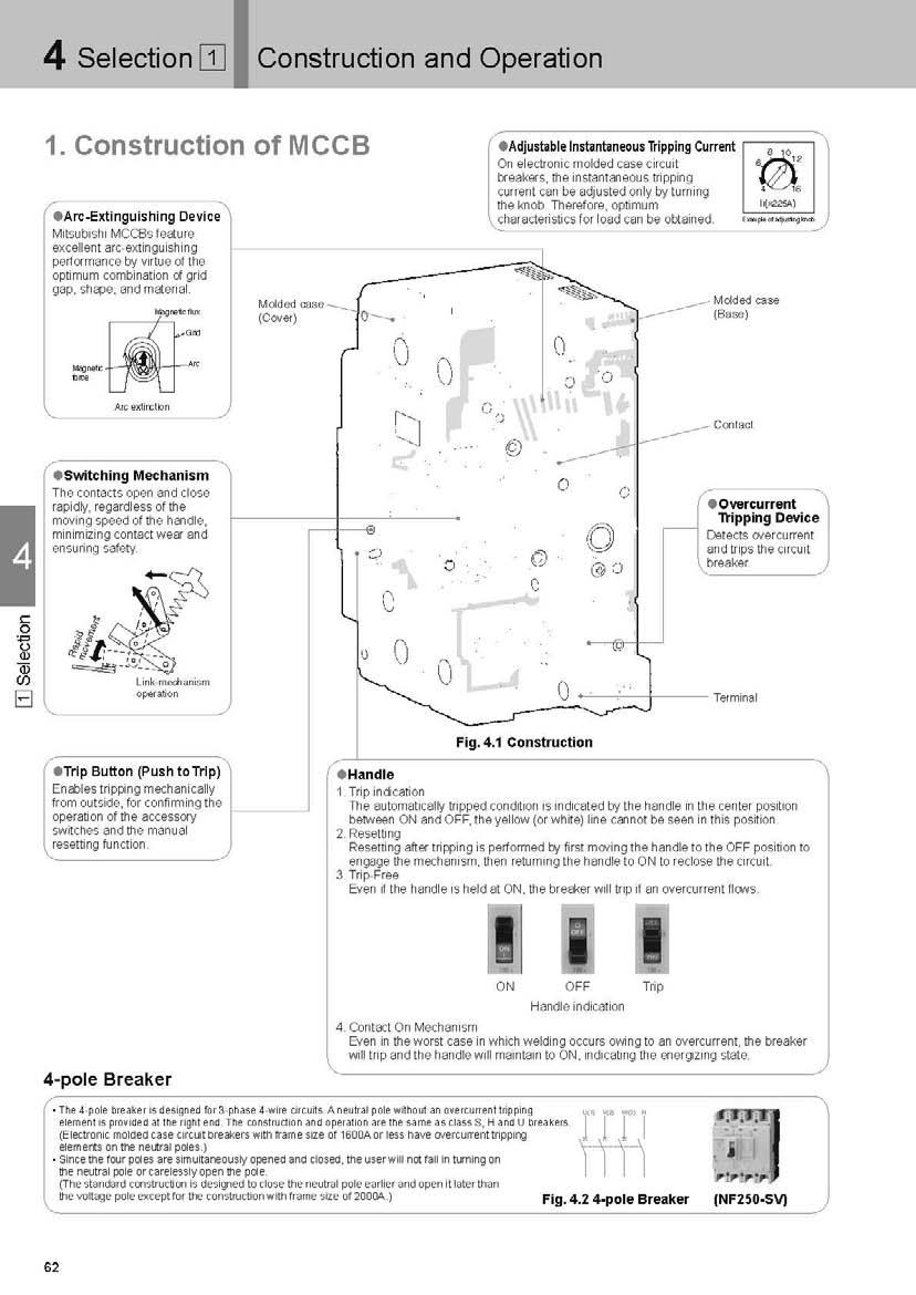
62
63 Selection 1 Construction and Operation Automatic Tripping Devices Thermal-Magnetic Type NF3-SV, NF63-CV/SV/HV, NF1-CV/SV/HV, NF-CV/SV/HV ( NF00-CW/SW, NF6-CW/SW, NF00-SDW, etc. ) Heater Armature Trip bar Bimetal 1. Time-Delay Operation An overcurrent heats and warps the bimetal to actuate the trip bar.. Instantaneous Operation If the overcurrent is excessive, the amature is attracted and the trip bar actuated. Thermal-Magnetic Type (NF1-SDW) Latch Bimetal Heater Trip bar Armature Stationary core Hydraulic-Magnetic Type (NF-CS etc.) Trip bar Armature Pipe Pole piece Silicon oil Moving core Damping spring Fig..3 Fig.. Fig.. Principle of Electronic Trip Relay (ETR) Operation (NF1-SEV/HEV, NF-SEV/HEV, etc.) ( NF00-SEW~NF00-CEW ) NF00-SEW~NF10-SEW, etc. CT CT CT CT Load-side terminal Power-source side terminal Rectifying circuit Breaking mechanism Trip coil WDT Test input Fig..6.1 Microcomputer A/D convertor CPU Characteristics S/W Input and output Characteristics setting part Coil Trigger circuit Over-current indication LED WDT: Watchdog timer circuit CT CT CT CT Fig Time-Delay Operation An overcurrent heats and warps the bimetal to actuate the trip bar.. Instantaneous Operation If the overcurrent is excessive, magnetization of the stationary core is strong enough to attract the armature and actuate the trip bar. 1. Time-Delay Operation At an overcurrent flow, the magnetic force of the coil overcomes the spring, the core closes to the pole piece, attracts the armature, and actuates the trip bar. The delay is obtained by the viscosity of silicon oil.. Instantaneous Operation If the overcurrent is excessive, the armature is instantly attracted, without the influence of the moving core. Power-source side terminal Breaking mechanism Trip coil Custom C Rectifying circuit CV PSS WDT Microcomputer A/D convertor Test input Characteristics Load-side setting part terminal Load-current indication LED (0%) CPU SSW LSW PSW Input and output Trigger circuit Over-current indication LED Pre-alarm indication LED Pre-alarm output WDT: Watchdog timer circuit 1. The current flowing in each phase is monitored by a current transformer (CT).. Each phase of the transformed current undergoes full-phase rectification in the rectifier circuit. 3. After rectification, each of the currents are converted by a peakconversion and an effective-value conversion circuit.. The largest phase is selected from the converted currents.. Each time-delay circuit generates a time delay corresponding to the largest phase. 6. The trigger circuit outputs a trigger signal.. The trip coil is excited, operating the switching mechanism. Number of tripping devices Descriptions (e.g. P1E and P0E) are not given in the number of poles fields of some models. For these models, the same number of overcurrent tripping devices as the number of poles is provided in the circuit breakers. poles: PE, 3 poles: 3P3E, poles: PE or P3E (Some models do not have overcurrent tripping devices for the neutral poles.) 63 Selection 1
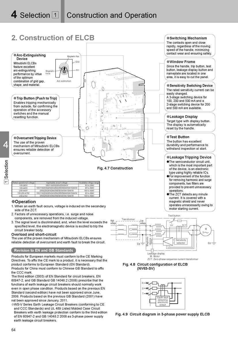
64
65 Selection Selection of MCCB and ELCB 1. Selecting Procedure MCCB (NF) Circuit used Applicable standard Phase and wire type, voltage, DC or AC, frequency, standard Applicable phase and wire type poles: 1-phase -wire 3 poles: 1-phase -wire, 1-phase 3-wire, 3-phase 3-wire poles: 3-phase -wire Specification list (pages 1 to 3) List of received certifications (page 6) Determination of rated current Kind and size of electric wire Kind and working conditions of load Selection conditions in internal standard and electrical equipment technical standards Relationship between temperature and electric wire (page 6) Selection of circuit breaker for motor branch circuit (page 3) Selection of circuit breaker for electric lamp or electric heater circuit (page 1) Selection of motor protection breaker (page ) Selection of circuit breaker for inverter circuit (page 6) Selection of circuit breaker on transformer primary side (page ) Determination of Transformer capacity Electric wire thickness and interrupting capacity length Application based on breaking capacity (page 0) Table of combinations for cascade breaking (page 3) Examination of coordination Selective breaking Operating characteristic curve (pages 1 to 1) Table of combinations for selective breaking (page 1) Determination of model Use Circuit s for special purpose (pages ) Installation method Accessories ELCB (NV) Circuit used Applicable standard Connection and molded case circuit breaker Internal accessories and external accessories Electric operation Phase and wire type, voltage, DC or AC, frequency, standard Installation and connection (pages 9 to ) Boxed Circuit s (page 13) Internal accessories (pages to 11) External accessories (pages 119 to 139) Electrical Operated Circuit s (pages 13 to 13) Specification list (pages to 3) List of received certifications (page 6) Selection Determination of rated current Kind and size of electric wire Kind and working conditions of load Selection conditions in internal standard and electrical equipment technical standards Relationship between temperature and electric wire (page 6) Selection of circuit breaker for motor branch circuit (page 3) Selection of circuit breaker for electric lamp or electric heater circuit (page 1) Selection of circuit breaker for inverter circuit (page 6) Selection of circuit breaker on transformer primary side (page ) Determination of Transformer capacity Electric wire thickness and interrupting capacity length Application based on breaking capacity (page 0) Table of combinations for cascade breaking (page 3) Determination of rated sensitivity current Purpose of protection Obligation of installation Purpose of protection (page ) Selection of rated sensitivity current of circuit breaker for inverter circuit (page 6) Method of switching between rated voltage and rated sensitivity current (page ) Examination of coordination Selective breaking Ground fault protection coordination Operating characteristic curve (pages 1 to 0) Table of combinations for selective breaking (page 1) Combinations of ground fault protection coordination and devices (page 91) Determination of model Use Circuit s for special purpose (pages ) Installation method Connection and molded case circuit breaker Installation and connection (pages 9 to ) Boxed Circuit s (page 13) Accessories Internal accessories and external accessories Electric operation Internal accessories (pages to 11) External accessories (pages 119 to 139) Electrical Operated Circuit s (pages 13 to 13)
66 Selection Selection of MCCB and ELCB Selection. Features and Performance Features of MCCB Molded Case Circuit s (NF) qtime-delay trip function This function conforms to the allowable current and time characteristics of electric wire and prevents operation caused by the staring current of a load device. When the overcurrent is large, the operating time is short, and when the overcurrent is small, the operating time is long. In the case of electronic type The electronic time-delay trip function includes a long time limit trip function conforming to the allowable current and time characteristics of conductor and a short time limit trip function for selective breaking for branch NFB. The short time limit function operates after a delay of some cycles (0.06 to 0.3 s) at overcurrent exceeding the short time limit tripping current. These functions can be adjusted by the knob. winstantaneous trip function This function breaks the circuit immediately when shortcircuit current flows. A circuit breaker on which the instantaneous tripping current is adjustable has the advantage that coordination in operation with other protective devices, such as electromagnetic switches and low-voltage air circuit breakers, can be easily obtained. The instantaneous operating time (total interrupting time) can be divided as shown in Fig. -. eoperating characteristic curve The operating characteristic curve indicates the relationship between magnitude of overcurrent and operating time. The maximum-minimum operating characteristic curve indicates that the operating time is in the range. Figs. -11 and -1 show examples of operating characteristic curves. Table -1 Overcurrent trip operating time (IEC 9-) Rated current of circuit breaker Operating time (A) for 1% current 63 or less Within 1 hr. Over 63 Within hrs. Occurrence of short-circuit Operation of tripping device Start of opening of contact Relay time Mechanism delay time Arc time Contact parting time Max. total interrupting time Completion of breaking Since the relay time is normally to ms, if large current flows for more than this time, the circuit breaker operates instantaneously. Fig.. Instantaneous operating time Operating time Max Min Max. total interrupting time Relay time Time delay tripping Instantaneous tripping Current Fig..11 Example of operating characteristic curve Operating time Recoverable time Long time limit tripping Long time limit tripping (adjustable) Max Min Short time limit tripping Current Short time limit tripping (adjustable) Instantaneous tripping (adjustable) Max. total interrupting time Instantaneous tripping Relay time Fig..1 Example of operating characteristic curve of electronic type Motor Protection s The motor protection breakers are circuit breakers to be used to protect general induction motors. They prevent motors being burnt not only by short-circuit current of circuits, but also by overcurrent caused by overload operation and locking of motors. The Motor Protection s are finely classified according to rated current so that the breakers can be applied to various types of motors. Although their time-delay trip and instantaneous trip functions are almost the same as those of MCCB, they are designed to operate within seconds to seconds at 0% of the rated current in consideration of protection from motor starting current and locked current. There are many kinds of motors, and the motors have various allowable characteristics for overcurrent. Therefore, when applying a motor breaker, it is necessary to compare the allowable characteristics and the operating characteristics of the motor breaker. Note that, particularly, submersible motors may not be protected by ordinary motor breakers because their allowable locked time is short. When the motor starting current is large and the starting time is long and when the frequency of intermittent operation is high, motor breakers are unsuitable. In such a case, the use of a combination of an electromagnetic switch and MCCB (combination starter) is recommended. 66
67 Selection Selection of MCCB and ELCB Characteristics of MCCB for DC circuits When a -pole MCCB ( V DC or less) is used on a DC circuit, connect the poles in series. When a 3- or MCCB is used, refer to page (for special DC voltage) or pages 1 to 1 (for DC). If the breaker is not connected as specified, its tripping characteristics and breaking performance will change, and it cannot be used. Current-limiting characteristic The current limiting refers to reduction of estimated short-circuit current depending on the circuit to prevent flow of the larger short-circuit current. The use of a class S, H or R which has excellent current-limiting characteristic or class U enables to reduce the passing energy at shortcircuiting and protect the devices in the electric circuit from electromagnetic force and thermal stress. Current Time Conventional short-circuit current waveform Max. peak current Passing current Max. peak current Ip (ka) Short-circuit current max. peak value NF63-SV/HV (ACV) NF-SV NF-HV NF1-SV/HV (1A) NF1-SV/HV (0 to 0A) NF1-SV/HV (A) NF1-SV/HV (0A) NF1-SV/HV (A) Short-circuit current r.m.s. (ka) sym. Fig..13 Passing current peak value characteristic of classes S and H ( VAC) Max. peak current Ip (ka) Short-circuit current max. peak value Short-circuit current r.m.s. (ka) sym. Fig..1 Passing current peak value characteristic of classes U ( VAC) NF00-UEW NF00-UEW NF-UV NF1-UV ( 6 ) 0 Max. passing energy I t (A s) Short-circuit current r.m.s. (ka) sym. Fig.. Passing I²t characteristic of class U ( VAC) NF00-UEW NF00-UEW NF-UV NF1-UV Selection Performance Short-circuit breaking performance Short-circuit current corresponding to the rated interrupting capacity is interrupted. Outline of short-circuit test (IEC 9-) q Rated limit short-circuit interrupting capacity (Icu) Operating duty: O 3 min CO w Rated service short-circuit interrupting capacity (Ics) Operating duty: O 3 min CO 3 min CO Upper limit of temperature rise of terminal after breaking: 0K or less O duty: The circuit breaker in the ON status carries and interrupts short-circuit current. CO duty: A shorted circuit is formed, and the circuit breaker is turned on to carry and interrupt short-circuit current. Opening/closing performance Table - shows the durability against opening and closing. See the durability against opening and closing as reference when using a circuit breaker as a switchgear. The durability against tripping by SHT (shunt tripping device), UVT (undervoltage tripping device) and trip button is % of the total durability against opening and closing. Note: Opening and closing operations are regarded as one time. If a circuit breaker is regularly used to trip, the life of the circuit breaker will be significantly reduced. Table - Durability of MCCB against opening and closing (IEC 9-) Rated current (A) 0 or less 1 to to to 0 1 or more Frequency of opening and closing (times/hour) Durability against opening and closing (times) With current flow current flow Total
68 Selection Selection of MCCB and ELCB 3. Current-carrying Capacity and Operating Temperature Operating current vs. ambient temperature Rated current of circuit breakers is adjusted for the rated ambient temperature. This is because circuit breakers are often installed in a casing as a switchboard or a control board, and temperature of the installed place of the breaker becomes higher than ambient temperature of the wires. If temperature of the installation site of circuit breakers greatly differ from the rated ambient temperature, it is necessary to correct rated current according to the temperature correction curve (shown in the Paragraph of characteristics and outside shape in the catalog). Load current can be increased up to the rated current corrected according to ambient temperature. However, set current rating with enough allowance while taking fluctuation of power voltage and load current into consideration so that maximum operating current may not exceed the rated current. (1) Cautionary instructions for using heat resistive wire Selection For using insulated wires of higher heat resistance than that of 0 V PVC insulated wire (allowable temperature C), it is necessary to take the following points into consideration. For circuit breakers, size of test wire is stipulated by each test current in IEC9-1 If size of connection wire is thinner than the test wire size, temperature of the breaker terminals increases and overcurrent tripping operation characteristic may change in some cases. (Operating time becomes shorter usually.) At motor load, for example, influence of change in operation characteristic by difference in size of connection wire is insignificant and can be disregarded because the load current is far lower than the rated current of the circuit breaker. Table -3 Size of test wire Range of test current (A) 0 < Conductor size (mm )
69 Selection Selection of MCCB and ELCB () Connection of aluminum conductors When aluminum conductors are connected, be careful to prevent the contact resistance (due to the oxidized film of aluminum) from being increased. The surface of the connection point of the aluminum conductors shall be properly treated by plating (zinc displacement-copper-silver) or by joint compound. If the treatment is done only by joint compound, reliability is low, this should be limited to when plating is impossible (eg. at site). For aluminum cables, use compression terminals that are exclusively for aluminum cables. The compression portion of the terminal shall be provided with taping, and the aluminum wire shall not be exposed to the atmosphere. Taping Circuit breaker Aluminum cable Model Compression terminal for aluminum cable (3) Maximum operating current of installation without clearance between breakers In case of installation without clearance between breakers, because malfunction failures can result by heat of breaker, use the operating current not to exceed the below value. Table - Fig..16 Example of connection of aluminum conductor Maximum operating current Selection BH BH-P BH-S BH-PS CP-BA CP-B CP-S NF-CS NF3-SV NF63-CV NV3-SV NV63-CV NF63-SV NF63-HV NV63-SV NV63-HV NF1-CV NF1-SGV NF1-SEV NV1-CV NF1-SV NF1-LGV NF1-HEV NV1-SV NF1-HV NF1-HGV NV1-HV NF1-RGV NF1-SGV NF1-LGV NF1-HGV NF-CV NF-LGV NV-CV NF-SV NF-SGV NV-SV NV-SEV NF-HV NF-HGV NF-RGV NV-HV NV-HEV 0% of rated current NF00-CW NF00-SW NF00-SEW NF00-HEW NV00-CW NV00-SW NV00-SEW NV00-HEW NF00-REW NF00-UEW NV00-REW NF6-CW NF6-SW NF6-SEW NF6-HEW NV6-CW NV6-SW NV6-SEW NV6-HEW NF6-REW NF00-CEW NF00-SDW NF00-SEW NF00-HEW NV00-SEW NV00-HEW NF00-REW NF00-UEW 90% of rated current 69
70 Selection Selection of MCCB and ELCB. Application of Circuit According to Breaking Capacity MCCB (NF) Table - VAC 3ph trans. capacity (kva) 1ph trans. capacity (kva) Breaking capacity (ka) (sym) Frame (A) to 000 or less 0 or less NF-CS NF-FAU (*1) NF-FAU (*1) to to 0 1 to 0 0 to 1 00 to 0 0 to 000 to NF3-SV NF63-CV NF63-SV NF63-HV NF1-CV Class C, FAU Series Classes S, H and R The correlation between transformers and interrupting capacities is intended for short-circuiting just under the secondary voltage of 3-phase standard transformer, V or 0 V, or the voltage of single-phase 3-wire transformer, V. ) ( NF-CV NF00-CW NF6-CW NF00-CEW NF00-SEW~NF10-SEW NF1-SEV NF1-HEV NF1-SV NF1-HV NF-SV NF-HV NF-SEV NF-HEV NF00-SW/SEW NF00-HEW NF6-SW/SEW NF6-HEW NF00-SEW NF00-HEW NF1-RGV NF-RGV NF00-REW NF6-REW NF00-REW NF1-UV NF-UV NF00-UEW NF00-UEW *1 The breaking capacity of NF-FAU and NF-FAU having a rated current of A is 1. ka. Selection Table -6 0VAC Trans. capacity (kva) Breaking capacity (ka) (sym) 3 Frame (A) or less to NF-CS NF3-SV NF63-CV NF63-SV NF63-HV 1 to 0 0 to 00 to to 00 NF1-SV NF1-CV NF1-SEV NF-SV NF-CV NF-SEV NF00-CW NF6-CW NF00-CEW NF1-HV NF1-HEV NF-HV NF-HEV NF00-SW/SEW NF6-SW/SEW NF00-SEW NF00-HEW NF6-HEW NF00-HEW NF1-RV NF-RV NF00-REW NF6-REW NF00-REW NF1-UV NF-UV NF00-UEW NF00-UEW 00 to 000 NF00-SEW~NF10-SEW ELCB (NV) Table - VAC 3ph trans. capacity (kva) 1ph trans. capacity (kva) Breaking capacity (ka) (sym) or less 0 or less to to 0 1 to 0 0 to 1 00 to 0 0 to NV-FAU (*1) NV3-SV Class C, FAU Series Classes S, H and R The correlation between transformers and interrupting current is intended for short-circuiting just under the secondary voltage of 3-phase standard transformer, V or 0 V, or the voltage of single-phase 3-wire transformer, V. ) ( 000 to NV-FAU (*1) NV63-CV NV63-SV NV63-HV Frame (A) NV1-CV NV1-SV NV1-HV NV1-SEV NV1-HEV NV-CV NV-SV NV-HV NV-SEV NV-HEV NV00-CW NV00-SW/SEW NV00-HEW NV00-REW NV6-CW NV6-SW/SEW NV6-HEW NV00-SEW NV00-HEW *1 The interrupting current of NF-FAU and NF-FAU having a rated current of A is 1. ka. Table - 0VAC Trans. capacity (kva) or less to 0 1 to 0 0 to 00 to to 00 Breaking capacity (ka) (sym) 3 NV3-SV NV63-CV NV63-SV NV63-HV NV1-CV NV1-HV NV1-SV NV1-SEV NV1-HEV NV-CV NV-SV NV-HV NV-SEV NV-HEV 00 NV00-CW NV00-SW/SEW NV00-HEW NV00-REW 0 6 NV6-CW NV6-SW/SEW NV6-HEW 00 NV00-SEW NV00-HEW Frame (A)
71 Selection Selection of MCCB and ELCB. Selection of Circuit for Electric Lamp or Heater Circuit The maximum working current is 0. times the rated current of each circuit breaker. MCCB (NF) Table -9 VAC Max. working current (A) In some lighting apparatuses, the service life of circuit breakers may be reduced by the influence of inrush current applied when the lamps are turned on. Periodically check for abnormal temperature rise of the circuit breaker in such an apparatus. Rated current of circuit breaker (A) NF-CS BH-P Breaking capacity (ka) V AC (Icu sym) BH-P (1/0V) BH-P (1/0V) NF3-SV NF63-CV NF1-CV NF-CV NF00-CW NF6-CW NF63-SV NF00-CEW NF63-HV NF00-SEW NF1-SEW NF10-SEW NF1-SV NF1-SV NF1-SEV NF1-HV NF1-SEV NF-SV NF-SEV NF1-HV NF00-SW NF00-SEW NF6-SW NF6-SEW NF00-SEW NF1-HV NF1-HEV NF1-RGV NF1-UV NF-HV NF-RGV NF-UV NF-HEV NF00 -HEW NF6 NF00-REW NF6-REW -HEW NF00 NF00-REW -HEW NF00 -UEW NF00 -UEW Table - 0VAC Max. working current (A) Rated current of circuit breaker (A) NF-CS Breaking capacity (ka) 0 V AC (Icu sym) NF63-CV NF3-SV NF1-CV NF3-SV NF63-SV NF63-HV NF63-CV NF-CV NF00-CW NF6-CW NF00-CEW NF1-SV NF00-SEW NF1-SEW NF10-SEW NF1-SV NF1-SV NF1-SEV NF1-HV NF1-SEV NF-SV NF- SEV NF1-HV NF1-HV NF1-HEV NF-HV NF-HEV NF1-RGV NF1-HEV NF00-SW NF00- NF00-SEW HEW NF6-SW NF6- NF6-SEW HEW NF00- NF00-SEW HEW NF1-RGV NF-RGV NF00-REW NF6-REW NF00-REW NF 1-UV NF -UV NF00-UEW NF00-UEW Selection 1
72 Selection Selection of MCCB and ELCB ELCB (NV) Table -11 VAC Max. working current (A) Rated current (A) Breaking capacity (ka) V AC (Icu sym) NV3-SV NV63-CV NV3-SV NV1-CV NV-CV NV63-SV NV00-CW NV6-CW NV00-SEW NV63-HV NV1-SV NV-SV NV-SEV NV1-HV NV1-HV NV1-SEV NV00-SW NV00-SEW NV6-SW NV6-SEW NV1- HV NV1- HEV NV- HV NV- HEV NV00 -HEW NV6 -HEW NV00 -HEW NV00 -REW Selection Table -1 0VAC Max. working current (A) Rated current (A) NV63-CV Breaking capacity (ka) 0 V AC (Icu sym) NV3-SV NV63-CV NV1-CV NV63-SV NV-CV NV63-HV NV00-CW NV6-CW NV00-SEW NV1-SV NV1-SV NV1-SEV NV-SV NV-SEV NV1-HV NV1-SEV NV1-HV NV1-HV NV1-HEV NV-HV NV-HEV NV00- SW NV00-SEW NV6-SW NV6-SEW NV1- HEV NV00- HEW NV6 -HEW NV00 -HEW NV00-REW
73 Selection Selection of MCCB and ELCB Y-Δ starting Direct-to-line starting Direct-to-line starting MCCB (NF) Table /0VAC for 3-phase induction motor Output (kw) current (A) Electromagnetic contactor Model N-N1.1 N-N1 Heater nominal (A) Breaking capacity (ka) V AC (Icu sym).. (*1) 0 1(*) 00 Model Rating Model Rating Model Rating Model Rating Model Rating Model Rating Model Type Rating Rating Model Rating Model Rating name NF-CS (3) NF3-SV (3) NF63-SV (3) NF63-HV () NF-CS NF3-SV NF63-SV NF63-HV () NF1-SV () NF1-SV () NF1-HV () NF1-HV () M NF1-UV () NF1-UV () N-N1 3.6 NF-CS NF3-SV NF63-SV NF63-HV NF1-SV () NF1-HV () N-N 6.6 NF-CS NF3-SV NF63-SV NF63-HV NF1-SV () NF1-HV NF1-UV. 9.1 N-N3 9 NF-CS 0 NF3-SV 0 NF63-SV 0 NF63-HV 0 NF1-SV 0 NF1-HV 0 NF1-UV 3. N1-N3 NF-CS NF3-SV NF63-SV NF63-HV NF1-SV NF1-HV NF1-UV. N N3 N N NF63-CV NF63-SV NF63-HV NF1-SV NF1-HV NF1-UV. 9 N3 N-N0 9 NF63-CV NF63-SV NF63-HV NF1-SV NF1-HV NF1-UV 11 N-N9 NF1-CV NF1-SV NF1-HV NF1-UV N-N1 NF1-CV 0 NF1-SV 0 NF1-HV 0 NF1-UV. NF63-CV NF63-SV NF63-HV NF1-SV NF1-HV NF1-UV. 9 9 NF63-CV NF63-SV NF63-HV NF1-CV NF1-SV NF1-HV NF1-UV 11 NF1-CV NF1-SV NF1-HV NF1-UV NF1-CV 0 NF1-SV 0 NF1-HV 0 NF1-UV 1. 6 N0-N1 6 NF1-CV 0 NF1-SV 0 NF1-HV 0 NF1-UV N9-N1 NF-CV 1 NF-SV 1 NF-HV 1 NF-UV 1 N1-N0 NF-CV 1 NF-SV 1 NF-HV 1 NF-UV 3 1 N1-N0 1 NF-CV NF-SV NF-HV NF-UV 16 N10-N00 1 NF00-CW 3 NF00-SW NF00-HEW NF00-REW NF00-UEW 19 N0-N00 10 NF6-CW 0 NF00-SW 0 NF00-HEW 0 NF00-REW 0 NF00-UEW 6 N0 N00 (N0) NF6-CW 0 NF6-SW 0 NF00-HEW 00 NF00-REW 00 NF00-UEW N0 N00 (N0 N00) 3 NF00-CEW 0 NF6-SW 0 NF6-HEW 0 NF6-REW 0 NF00-UEW 1 3 N0 N00 (N0 N00) 3 NF00-CEW 0 NF6-SEW 0 NF6-HEW 0 NF6-REW 0 NF00-UEW 13 0 (N0 N00) 0 NF00-SEW (N0 N00) 0 NF1-SEW (N00) 0 NF10-SEW 00 Notes *1 The breaking capacity of NF-CV is 36kA. * The breaking capacity of NF00- to 10-SEW is 1kA. Y-Δ starting Direct-to-line starting Direct-to-line starting 6. Selection of Circuit for Motor Branch Circuit (direct-to-line starting or Y-Δ starting) Table -1 00/0VAC for 3-phase induction motor For motor Fullload For motor Fullload Output (kw) current (A) Electromagnetic contactor Model N-N1 N-N1 N-N1 N-N1 N-N1 N11-N3 N1-N3 N-N9 N-N9 N-N1 N0-N1 N9-N1 N1-N0 N1-N0 N10-N00 N10-N00 N0-N00 Heater nominal (A) Model NF-CS NF-CS NF-CS NF-CS NF-CS NF-CS NF-CS NF-CS Rating (3) (3) 0. Model NF3-SV NF3-SV NF3-SV NF3-SV NF3-SV NF3-SV NF3-SV NF3-SV NF63-CV NF63-SV NF63-HV NF63-CV NF63-CV NF63-CV NF63-CV NF63-CV NF63-CV NF63-CV Rating (3) (3) 0 0. Model NF63-SV NF63-SV NF63-SV NF63-SV NF63-SV NF63-SV NF63-SV NF63-SV NF63-SV NF63-SV NF63-SV NF63-SV NF63-SV NF63-SV NF63-SV Rating (3) (3) 0 0 Breaking capacity (ka) V AC (Icu sym) (*1) (*) Model NF63-HV NF63-HV NF63-HV NF63-HV NF63-HV NF63-HV NF63-HV NF63-HV NF63-HV NF63-HV NF63-HV NF1-CV NF1-CV Rating 0 NF63-HV NF1-CV NF1-CV NF1-CV 0 NF1-CV 0 NF-CV 1 0 NF1-UV () () Electromagnetic switch NF1-CV NF-HV NF1-CV 0 0 NF-HV 0 NF1-CV 0 0 NF-HV 0 NF-CV 1 1 NF-HV 1 NF-CV 1 1 NF-HV 1 NF-CV NF-HV NF-SEV NF-HEV NF00-REW NF00-SW 3 NF00-HEW 0 NF00-REW 0 NF00-SW 00 NF00-HEW 00 NF00-REW 00 NF6-SW 0 NF6-HEW 0 NF6-REW 0 NF6-SW 0 NF6-HEW 0 NF6-REW 0 NF6-SW 0 NF6-HEW 0 NF6-REW 0 NF6-SEW 00 NF6-HEW 0 NF6-REW NF00-SEW 00 NF00-HEW 00 NF00-REW 00 NF00-UEW 00 Notes *1 The breaking capacity of NF-SV and NF-SEV is 36kA. * The breaking capacity of NF00-SW is ka. *3 The breaking capacity of NF00- to 00-REW is 1kA. Remarks: 1. Circuit breakers are selected under the starting conditions shown in the right table.. Protection coordination is examined under the condition of cold start at 0 C. Starting conditions for selection 3. The ratings in parentheses apply to cases where thermal relays with saturating reactor are used. Direct-to-line. Although the inrush current upon switching to Δ connection fluctuates depending on the residual magnetic flux at star Startup inrush current ( full-load current) Motor capacity starting time starting, Δ connection closing phase or power supply transformer capacity, in most cases, the inrush current is less than (0%) Direct-to-line starting Y-Δ starting the values shown in the right table. 0. to.kw s 1 times 16 times. The maximum starting current is the effective value of current (value after transient phenomena disappear) at the time when the rotator starts to rotate. 6. It was assumed that the Y-Δ starting would be performed by the open transition method which is a general method but is known to carry large transient inrush current. 11 to to Model Rating Model NF1-SV () NF1-HV () NF1-SV () NF1-HV () NF1-SV () NF1-HV () NF1-SV () NF1-HV () NF1-SV () NF1-HV () NF1-SV 0 NF1-HV 0 NF1-SV NF1-HV NF1-SV NF1-HV NF1-SV NF1-HV NF1-SV NF1-SV NF1-SV NF1-SV NF1-SV NF-SV NF1-SV NF1-SV NF1-SV NF1-SV NF1-SV NF1-SV NF1-SV NF1-SV NF-SV NF-SV NF-SV Motor is protected from overload by electromagnetic switch. Circuit breaker is installed to protect circuit from short-circuit. Rating 0 Model NF1-HV NF1-HV NF1-HV 0 NF1-HV 0 0 NF1-HV 0 1 NF-HV 1 NF-HV NF-HV NF-HV NF-HV NF-HV Rating 0 0 Model Rating 1(*3) 00 Model Rating Model Rating NF1-UV () NF1-UV () NF1-UV () NF1-UV () NF1-UV () NF1-UV 0 NF1-UV NF1-UV NF1-UV NF1-UV NF1-UV NF1-UV NF1-UV 0 NF1-UV 0 NF-UV 1 NF1-UV NF1-UV NF1-UV NF1-UV NF1-UV NF1-UV NF1-UV NF1-UV NF-UV NF-UV NF-UV NF00-UEW NF00-UEW NF00-UEW NF00-UEW NF00-UEW NF00-UEW NF00-UEW Selection
74 Selection Selection of MCCB and ELCB Y-Δ starting Direct-to-line starting Direct-to-line starting ELCB (NV) Table - 00/0VAC for 3-phase induction motor Output (kw) current (A) Electromagnetic contactor Heater Model nominal (A) N-N1 N-N1 N-N1 N-N N-N3 N1-N3 N-N9 N-N1 N0-N1 N9-N1 N1-N0 N1-N0 N10-N00 N0-N Model NV-CS NV-CS NV-CS NV-CS NV-CS NV-CS Notes *1 The breaking capacity of NV3-SV is ka. * The breaking capacity of NV-CV is 36kA. Rating () 0. Model NV63-CV NV63-CV NV63-CV NV63-CV NV63-CV NV63-CV NV63-CV NV63-CV NV63-CV NV63-CV Rating () 0 (*1) Model NV3-SV () NV63-HV () NV3-SV NV3-SV NV3-SV NV3-SV NV3-SV NV63-SV NV63-SV NV63-SV NV63-SV Rating () () 0 Breaking capacity (ka) V AC (Icu sym) (*) Model NV63-HV NV63-HV NV63-HV NV63-HV NV63-HV NV63-HV NV63-HV NV63-HV NV63-HV Rating () () 0 Model Rating Model Rating NV1-SV () NV1-SV () NV1-SV () NV1-SV NV1-SV 0 NV1-SV NV1-SV NV1-SV NV1-CV NV1-CV 0 NV1-SV Model NV1-SV 0 NV1-HV 0 NV1-SV NV1-HV NV1-CV NV1-CV NV1-SV NV1-SV NV1-HV NV1-HV NV1-CV 0 NV1-SV 0 NV1-CV 0 NV1-SV 0 NV-CV 1 NV-CV 1 NV-CV NV1-HV 0 NV1-HV 0 NV-SV 1 NV-HV 1 NV-SV 1 NV-HV 1 NV-SV NV-HV NV00-CW 3 NV00-SW NV00-HEW NV00-REW NV6-CW 0 NV00-SW 0 NV00-HEW 0 NV00-REW 0 NV6-CW 0 NV00-SEW 00 NV00-HEW 00 NV00-REW 00 NV6-SEW 0 NV6-HEW 0 NV6-SEW 0 NV6-HEW 0 Rating 0 Model Rating NV1-HV () NV1-HV () NV1-HV () NV1-HV () NV1-HV 0 NV1-HV NV1-HV NV1-HV NV1-HV 1 Model Rating Table /0VAC for 3-phase induction motor Selection Y-Δ starting Direct-to-line starting Direct-to-line starting For motor Output (kw) For motor Fullload Fullload current (A) Electromagnetic contactor Heater Model nominal (A) N-N1 N-N1 N-N1 N-N1 N-N1 N11-N3 N1-N3 N-N9 N-N9 N-N1 N0-N1 N9-N1 N1-N0 N1-N0 N10-N00 N10-N00 N0-N Model NV63-CV NV63-CV NV63-CV NV63-CV NV63-CV NV63-CV NV63-CV NV63-CV NV63-CV NV63-CV NV63-CV NV63-CV NV63-CV NV63-CV Notes *1 The breaking capacity of NV-SV and NV-SEV is 36kA. * The breaking capacity of NV00-SW is ka. Remark: 1. For the selecting conditions, please refer to the remarks on page 3. Example of Y-Δ starting current waveform (crest value envelope). Rating () () 0 0 Model NV3-SV NV3-SV NV3-SV NV3-SV NV3-SV NV3-SV NV3-SV NV3-SV NV3-SV Rating () () 0. Model NV63-SV NV63-SV NV63-SV NV63-SV NV63-SV NV63-SV NV63-SV NV63-SV NV63-SV NV63-SV NV63-SV NV63-SV NV63-SV NV63-SV Rating () () 0 0 Breaking capacity (ka) V AC (Icu sym) (*1) Model NV63-HV NV63-HV NV63-HV NV63-HV NV63-HV NV63-HV NV63-HV NV63-HV NV63-HV NV63-HV NV1-CV NV1-CV NV1-CV NV1-CV NV63-HV NV63-HV NV63-HV NV1-CV NV1-CV NV1-CV NV1-CV NV1-CV Rating () () () () () Pump load S phase current Model NV-CV 1 NV-CV NV-CV NV-CV Rating 1 1 Steady load current crest value = 3A Inrush current crest value at switching to Δ connection660a Model NV1-SV NV1-SV NV1-SV NV1-SV NV1-SV NV1-SV NV1-SV NV1-SV NV1-SV NV1-SV NV1-SV NV1-SV NV1-SV NV1-SV NV-SV NV1-SV NV1-SV NV1-SV NV1-SV NV1-SV NV1-SV NV1-SV NV1-SV NV-SV NV-SV NV-SV NV-SEW Rating () () () () () (*) Model NV1-HV NV1-HV NV1-HV NV1-HV NV1-HV NV1-HV NV1-HV NV1-HV NV1-HV NV1-HV NV1-HV NV1-HV NV1-HV NV1-HV NV1-HV NV1-HV NV1-HV NV1-HV NV1-HV NV1-HV NV1-HV NV1-HV Rating () () () () () Model Rating NV-HV 1 NV-HV 1 NV-HV 1 NV-HV NV-HEW NV00-REW NV00-SW 3 NV00-HEW 0 NV00-REW 0 NV00-SW 00 NV00-HEW 00 NV00-REW 00 NV6-SEW 0 NV6-HEW 0 NV6-SEW 0 NV6-HEW Model Rating Operation in Y connection Operation in Δ connection
75 Selection Selection of MCCB and ELCB. Selection of Motor Protection Motor Protection s Table -1 for 3-phase induction motor In principle, the operating characteristic curve of a selected motor breaker must be lower than the heat characteristic of the motor. The following table shows the rated capacities of Mitsubishi s standard squired-cage 3-phase motors (). The starting conditions are shown in the table. Model Motor Protection NF3-SV NF63-CV NF63-SV NF1-SV NF-SV Rated breaking capacity (ka) V V % starting time limit (s) Startup inrush current limit (%) Example of rated capacity of motor (kw) 00/0V 00/0V 100 Rated current 3 A or less: 0 A or more: 100 Rated current 3 A or less: 0 A or more: 100 Rated current 3 A or less: 0 A or more: 100 Rated current 10 Rated current Model for combination with electromagnetic contactor N-N Selection (1.) (16) N11-N3 N1-N3 N0-N3 N () 3 N3 N-N (0) N-N Remarks: 1. Fot the rated curent in parentheses, breakers will be manufactured to order.. The approximate values of inrush current at direct-to-line starting are shown below. Up to. kw: 00% 11 kw or more: 100% kw or more: 100% When the starting current is large and the starting power factor is low, a combination with an electromagnetic switch selected in accordance with Table of selection of circuit breaker for motor branch circuit shown on page 3 is suitable. Cautions (1) Note that any circuit breaker operates when the startup inrush current, starting current and starting time exceed the conditions shown in the above table. Particularly, high-efficiency motors generally have higher starting current and lower starting torque compared to general-purpose motors, and motor breakers cannot be used for such motors. () Note that a circuit breaker may operate when an electromagnetic contactor is opened or closed while a motor is running. (3) Select a motor breaker having rated current approx. 1.0 to 1.1 times higher than the full load current of motor N-N1 N0-N1 N90-N1 N1-N0 N1-N00 N10-N00 N0-N00
76 Selection Selection of MCCB and ELCB Selection. Selection of Circuit for Inverter Circuit Selection of Circuit for Inverter Circuit Since current containing harmonic components will flow, the rated current of circuit breaker must be approx. 1. times the inverter input current. Power supply NFB Example 1 NV Example NV R S T 6mm m Noise filter Inverter 6mm 0m IM I 1 I n I I m mm m Noise filter Inverter Inverter mm 0m IM I 1 I n I I m U V W Motor IM Selection of rated sensitivity current of Earth Leakage Circuit for Inverter Circuit Select the rated sensitivity current as stated below. Circuit breakers for harmonics and surge: Rated sensitivity current IΔn {Ig1 + Ign + Ig + Igm} General circuit breakers: Rated sensitivity current IΔn {Ig1 + Ign + 3 (Ig + Igm)} 3-phase 0V.kW 3-phase 0V kw Install MCCB or ELCB on the primary side (power supply side) of the inverter. If it is installed on the secondary side, it may cause electronic circuit trouble or overheating. Note The life cycle of the circuit breaker for the circuit on the inverter primary side will be reduced under the influence of transient inrush current. Install a switch. Table -1 3-phase 00 V class Inverter input capacity kva Rated current of circuit breaker A Ig1, Ig: Leakage current from line Ign: Leakage current from noise filter on inverter input side Igm: Leakage current from motor operating on commercial power supply Inverter input capacity kva Rated current of circuit breaker A Table Examples of leakage current from line when IV cable is wired in close contact with ground (wiring in metallic conduit) (3-phase 0V Hz) Wire size mm Leakage current/km ma Table -19- Example of leakage current from 3-phase induction motor (0V Hz) Motor output (kw) Leakage current (ma) Example of selection 1 Example of selection for harmonics and surge General breaker for harmonics and surge General breaker Leakage current Ig1 13 = = 0.6 Leakage current Ig1 0 = = Leakage current Ign 0 (without noise filter) Leakage current Ign 0 (without noise filter) Leakage current Ig = =.1 Leakage current Ig 0 =.1 0 = Leakage current Igm = 0. Leakage current Igm =.16 Total leakage current Ig Total leakage current Ig.. Rated sensitivity 0 00 Rated sensitivity current (> Ig ) current (> Ig ) 0 0 Remarks: 1. Circuit breakers for harmonics and surge can detect earth fault on the secondary side of inverter only when the operating frequency is 10 Hz or less. In the case of star connection by neutral point grounding method, the sensitivity current for earth fault on the inverter secondary side is degraded. In this case, for protective ground for load device, apply Class C grounding ( Ω or less).. For general circuit breakers, the leakage current from the line between inverter and motor shall be calculated as three times the leakage current at the commercial frequency in consideration of harmonic content. 3. For the model names of circuit breakers for harmonics and surge, refer to the specification list in Section of this document. Models not for harmonics and surge are general breakers. 6
77 Selection Selection of MCCB and ELCB 9. Selection of Circuit for Transformer Primary Side Notes 1. The life cycle of the circuit breaker for the circuit on the transformer primary side will be significantly reduced under the influence of excited inrush current. Install a switch to open and close the circuit.. Select a circuit breaker based on the example of excited inrush current of each transformer. When using a circuit breaker for a transformer, check the magnitude of excited inrush current with the transformer manufacturer. Single-phase -V Table -0-1 MCCB Transformer capacity kva Rated primary current A Example of transformer excited inrush current 1 Crest value of first wave (multiple) Model NF1-CV(*1) NF1-CV, NF1-SV, NF1-HV NF1-SEV, NF1-HEV NF-CV, NF-SV, NF-HV NF-SEV, NF-HEV NF-CV, NF-SV, NF-HV NF-SEV, NF-HEV NF00-CW NF00-SW NF00-SEW, NF00-HEW NF00-SW NF00-SEW, NF00-HEW NF00-SEW, NF00-HEW NF6-SW NF6-SEW(*1) NF00-SEW NF00-SEW(*1) NF1-SEW NF00-SEW NV1-CV, NV1-SV, NV1-HV NV1-SEV, NV1-HEV NV-CV, NV-SV, NV-HV NV-SEV, NV-HEV NV-CV, NV-SV, NV-HV NV-SEV, NV-HEV NV00-CW NV00-SW NV00-SEW, NV00-HEW NV00-SW NV00-SEW, NV00-HEW NV00-SEW, NV00-HEW NV6-SEW Rating A Example of transformer excited inrush current Crest value of Rating first wave Model A (multiple) NF63-CV(*1) NF1-CV(*1) NF1-CV, NF1-SV NF1-SEV NF1-CV(*1) NF-CV, NF-SV NF1-CV(*1) NF-CV, NF-SV NF-SEV NF-CV, NF-SV NF-SEV NF00-SW NF00-SEW NF00-SEW NF6-SEW NF00-SEW(*1) NF10-SEW Table -0- ELCB Transformer Rated Example of transformer excited inrush current 1 Example of transformer excited inrush current capacity primary Crest Crest Rating Rating current value of Model value of kva first wave A A first wave Model A (multiple) (multiple) NV1-CV, NV1-SV NV1-SEV NV1-SEV NV-CV, NV-SV NV-CV, NV-SV NV-SEV NV-CV, NV-SV NV-SEV NV00-SW NV00-SEW NV00-SEW Example of transformer excited inrush current 3 Crest value of first wave Model (multiple) NF63-CV(*1) NF63-CV, NF63-SV NF1-CV(*) NF1-SV NF63-CV(*1) NF1-CV(*1)(*) NF1-CV, NF1-SV NF1-CV(*1) NF1-CV, NF1-SV NF1-CV(*1) NF-CV, NF-SV NF-CV, NF-SV NF-SEV NF00-SW NF00-SEW NF00-SEW(*1) NF6-SEW NF6-SEW NF00-SEW(*1) NF10-SEW NV63-CV, NV63-SV NV1-CV NV1-SV NV1-SEV NV1-CV, NV1-SV NV1-SEV NV1-CV, NV1-SV NV-CV, NV-SV NV-CV, NV-SV NV-SEV NV-CV, NV-SV NV-SEV NV00-SW NV00-SEW NV6-SEW NV00-SEW NV6-SEW Rating A () () Example of transformer excited inrush current 3 Crest value of first wave Model (multiple) NV6-SEW Notes *1 Examples of selection of high-instantaneous circuit breakers (special models) for primary side of transformer. * The circuit breakers with rating in parentheses are special models. Remarks: 1. For the circuit breakers whose rated current is adjustable, the rated current values are shown.. The crest value of the first wave of excited inrush current shall be calculated based on the multiple for the crest value of the first wave in the table, and the calculated value shall not exceed the lower limit crest value of instantaneous tripping current of circuit breaker. The circuit breakers are selected on condition that the transformer rated current value does not exceed 0.9 times the circuit breaker rated current. If the multiple for the crest value of the first wave is different from that shown in the table, a circuit breaker must be separately selected. Rating A Selection
78 Selection Selection of MCCB and ELCB Selection Single-phase 0-V Table -1-1 MCCB Transformer capacity kva Rated primary current A Example of transformer excited inrush current 1 Peak value of first wave (multiple) Model NF63-CV(*1) NF63-CV, NF63-SV, NF63-HV NF1-CV, NF1-SV, NF1-HV NF63-CV(*1) NF1-CV, NF1-SV, NF1-HV NF1-CV(*1) NF1-CV, NF1-SV, NF1-HV NF1-CV(*1) NF-CV, NF-SV, NF-HV NF-SEV, NF-HEV NF-CV, NF-SV, NF-HV NF-SEV, NF-HEV NF-SEV, NF-HEV NF00-CW NF00-SW NF00-SW NF00-SEW, NF00-HEW NF00-SEW, NF00-HEW NF6-SW NF6-SEW, NF6-HEW NF00-SEW(*1) NF6-SW NF6-SEW, NF6-HEW NF6-SEW(*1) NF00-SEW(*1) NF1-SEW NV63-CV, NV63-SV, NV63-HV NV1-CV NV1-SV, NV1-HV NV1-CV, NV1-SV, NV1-HV NV1-CV, NV1-SV, NV1-HV NV1-SEV, NV1-HEV NV-CV, NV-SV, NV-HV NV-SEV, NV-HEV NV-CV, NV-SV, NV-HV NV-SEV, NV-HEV NV-SEV, NV-HEV NV00-CW NV00-SW NV00-SW NV00-SEW, NV00-HEW NV00-SEW, NV00-HEW NV6-SEW, NV6-HEW NV6-SEW, NV6-HEW NV00-SEW, NV00-HEW Rating A Table -1- ELCB Transformer Rated Example of transformer excited inrush current 1 capacity primary Peak Rating current value of Model kva first wave A A (multiple) Example of transformer excited inrush current Peak value of Rating first wave Model A (multiple) NF3-SV NF63-CV, NF63-SV NF1-SV NF63-CV(*1) NF63-CV, NF63-SV NF1-CV, NF1-SV NF63-CV(*1) NF1-CV, NF1-SV NF1-CV(*1) NF1-CV, NF1-SV NF1-CV(*1) NF-CV, NF-SV NF-SEV NF-CV, NF-SV NF-SEV NF00-SW NF00-SEW NF00-SEW NF00-SEW(*1) NF6-SEW NF00-SEW(*1) NF10-SEW Example of transformer excited inrush current Peak value of Rating first wave Model A (multiple) NV3-SV NV63-CV, NV63-SV NV1-SV NV63-CV, NV63-SV NV1-CV, NV1-SV NV1-CV, NV1-SV NV1-SEV NV1-CV, NV1-SV NV1-SEV NV-CV, NV-SV NV-SEV NV-CV, NV-SV NV-SEV NV00-SW NV00-SEW NV00-SEW NV6-SEW NV00-SEW Example of transformer excited inrush current 3 Peak value of Rating first wave Model A (multiple) NF3-SV, NF63-CV, NF63-SV NF1-SV NF3-SV, NF63-CV, NF63-SV NF1-SV NF1-CV(*) NF63-CV(*1) NF63-CV, NF63-SV NF1-CV(*) NF1-SV NF63-CV(*1) NF1-CV(*1)(*) NF1-CV, NF1-SV NF1-CV(*1) NF1-CV, NF1-SV NF1-CV(*1) NF-CV, NF-SV NF-SEV NF00-SW NF00-SEW NF00-SEW NF00-SEW(*1) NF6-SEW NF00-SEW(*1) NF1-SEW NV3-SV NV63-CV, NV63-SV NV1-SV NV3-SV NV63-CV, NV63-SV NV1-SV NV63-CV, NV63-SV NV1-CV NV1-SV NV1-CV, NF1-SV NV1-SEV NV1-CV, NF1-SV NV1-SEV NV-SV, NV-SV NV-SEV 0 () () () Example of transformer excited inrush current 3 Peak value of first wave Model (multiple) NV-SEV NV00-SW 00 NV00-SEW NV00-SEW NV6-SEW 00 NV00-SEW Notes *1 Examples of selection of high-instantaneous circuit breakers (special models) for primary side of transformer. * The circuit breakers with rating in parentheses are special models. Remarks: 1. For the circuit breakers whose rated current is adjustable, the rated current values are shown.. The peak value of the first wave of excited inrush current shall be calculated based on the multiple for the peak value of the first wave in the table, and the calculated value shall not exceed the lower limit peak value of instantaneous tripping current of circuit breaker. The circuit breakers are selected on condition that the transformer rated current value does not exceed 0.9 times the circuit breaker rated current. If the multiple for the peak value of the first wave is different from that shown in the table, a circuit breaker must be separately selected. Rating A 0 1 1
79 Selection Selection of MCCB and ELCB 3-phase -V Table -1-3 MCCB Transformer capacity kva Rated primary current A Example of transformer excited inrush current 1 Peak value of first wave (multiple) Model NF3-SV NF63-CV, NF63-SV, NF63-HV NF1-SV, NF1-HV NF63-CV(*1) NF63-CV, NF63-SV, NF63-HV NF1-CV(*) NF1-SV, NF1-HV NF63-CV(*1) NF63-CV, NF63-SV, NF63-HV NF1-CV(*1) NF1-CV, NF1-SV, NF1-HV NF63-CV(*1) NF1-CV, NF1-SV, NF1-HV NF1-CV(*1) NF1-CV, NF1-SV, NF1-HV NF1-CV(*1) NF-CV, NF-SV, NF-HV NF-SEV, NF-HEV NF-SEV, NF-HEV NF00-CW NF00-SW NF00-SW NF00-SEW, NF00-HEW NF00-SEW(*1) NF6-SW NF6-SEW, NF6-HEW NF6-SEW, NF6-HEW NF00-SEW(*1) NF10-SEW NV3-SV NV63-CV, NV63-SV, NV63-HV NV1-SV, NV1-HV Rating A () Example of transformer excited inrush current Peak value of Rating first wave Model A (multiple) NF3-SV, NF63-CV, NF63-SV NF1-SV NF63-CV(*1) NF63-CV, NF63-SV NF1-CV, NF1-SV NF63-CV(*1) NF63-CV, NF63-SV NF1-CV, NF1-SV NF1-CV(*1) NF1-CV, NF1-SV NF1-CV(*1) NF1-SEV NF-CV, NF-SV NF-CV, NF-SV NF-SEV NF00-CW NF00-SW NF00-SEW NF00-SW NF00-SEW NF00-SEW NF6-SEW NF00-SEW NF1-SEW NF10-SEW Example of transformer excited inrush current 3 Peak value of Rating first wave Model A (multiple) NF3-SV, NF63-CV, NF63-SV NF1-SV NF3-SV, NF63-CV, NF63-SV NF1-CV(*) NF1-SV NF63-CV, NF63-SV NF1-CV(*) NF1-SV NF63-CV(*1) NF63-CV, NF63-SV NF1-CV, NF1-SV NF1-CV(*1) NF1-CV, NF1-SV NF1-CV(*1) NF-CV, NF-SV NF-CV, NF-SV NF-SEV NF00-SW NF00-SEW NF00-SW NF00-SEW NF6-SW NF6-SEW NF00-SEW NF00-SEW NF10-SEW Table -1- ELCB Transformer Rated Example of transformer excited inrush current 1 Example of transformer excited inrush current Example of transformer excited inrush current 3 capacity primary Peak Peak Peak Rating Rating Rating current value of Model value of value of kva first wave A A first wave Model A first wave Model A (multiple) (multiple) (multiple) NV3-SV NV63-CV, NV63-SV NV1-SV NV3-SV NV63-CV, NV63-SV NV1-SV 0 0 () () Selection. 0.6 NV63-CV, NV63-SV, NV63-HV NV1-CV NV1-SV, NV1-HV 6 NV63-CV, NV63-SV NV1-CV NV1-SV 1 NV3-SV NV63-CV, NV63-SV NV1-SV NV63-CV, NV63-SV, NV63-HV NV1-CV, NV1-SV, NV1-HV NV1-CV, NV1-SV, NV1-HV NV1-SEV, NV1-HEV NV1-CV, NV1-SV, NV1-HV NV1-SEV, NV1-HEV NV-CV, NV-SV, NV-HV NV-SEV, NV-HEV NV-SEV, NV-HEV NV00-CW NV00-SW NV00-SW NV00-SEW, NV00-HEW NV6-SEW, NV6-HEW NV00-SEW, NV00-HEW NV6-SEW, NV6-HEW NV63-CV, NV63-SV NV1-CV, NV1-SV NV1-CV, NV1-SV NV1-SEV NV1-SEV NV-CV, NV-SV NV-CV, NV-SV NV-SEV NV00-CW NV00-SW NV00-SEW NV00-SEW NV00-SW NV00-SEW NV6-SEW NV00-SEW NV63-CV, NV63-SV NV1-CV NV1-SV NV63-CV, NV63-SV NV1-CV, NV1-SV NV1-CV, NV1-SV NV1-SEV NV-CV, NV-SV NV1-SEV NV-CV, NV-SV NV-SEV NV00-SW NV00-SEW NV00-SW NV00-SEW NV6-SEW NV00-SEW NV00-SEW Notes *1 Examples of selection of high-instantaneous circuit breakers (special models) for primary side of transformer. * The circuit breakers with rating in parentheses are special models. Remarks: 1. For the circuit breakers whose rated current is adjustable, the rated current values are shown.. The peak value of the first wave of excited inrush current shall be calculated based on the multiple for the peak value of the first wave in the table, and the calculated value shall not exceed the lower limit peak value of instantaneous tripping current of circuit breaker. The circuit breakers are selected on condition that the transformer rated current value does not exceed 0.9 times the circuit breaker rated current. If the multiple for the peak value of the first wave is different from that shown in the table, a circuit breaker must be separately selected
80 Selection Selection of MCCB and ELCB Selection 3-phase 0-V Table -1- MCCB Transformer capacity kva Table -1-6 ELCB Transformer capacity kva Rated primary current A Rated primary current A Example of transformer excited inrush current 1 Peak value of first wave (multiple) Model NF3-SV NF63-CV, NF63-SV, NF63-HV NF1-SV, NF1-HV NF3-SV NF63-CV, NF63-SV, NF63-HV NF1-SV, NF1-HV NF3-SV NF63-CV, NF63-SV, NF63-HV NF1-CV(*) NF1-SV, NF1-HV NF63-CV(*1) NF63-CV, NF63-SV, NF63-HV NF1-CV, NF1-SV, NF1-HV NF1-SEV, NF1-HEV NF63-CV(*1) NF63-CV, NF63-SV, NF63-HV NF1-CV(*1) NF1-CV, NF1-SV, NF1-HV NF63-CV(*1) NF1-CV(*1) NF1-CV, NF1-SV, NF1-HV NF1-CV(*1) NF-CV, NF-SV, NF-HV NF-SEV, NF-HEV NF-CV, NF-SV, NF-HV NF-SEV, NF-HEV NF-CV, NF-SV, NF-HV NF-SEV, NF-HEV NF00-CW NF00-SW NF00-SEW, NF00-HEW NF00-SW NF00-SEW, NF00-HEW NF6-CW NF6-SW NF6-SEW, NF6-HEW NF00-SEW(*1) NF1-SEW NV3-SV(*1) NV63-CV, NV63-SV(*1) NV63-HV NV1-SV, NV1-HV NV3-SV NV63-CV, NV63-SV, NV63-HV NV1-SV, NV1-HV NV3-SV NV63-CV, NV63-SV, NV63-HV NV1-CV NV1-SV, NV1-HV NV63-CV, NV63-SV, NV63-HV NV1-CV, NV1-SV, NV1-HV NV1-SEV, NV1-HEV NV63-CV, NV63-SV, NV63-HV NV1-CV, NV1-SV, NV1-HV NV1-CV, NV1-SV, NV1-HV NV1-SEV, NV1-HEV NV-CV, NV-SV, NV-HV NV-SEV, NV-HEV NV-CV, NV-SV, NV-HV NV-SEV, NV-HEV NV-CV, NV-SV, NV-HV NV-SEV, NV-HEV NV00-CW NV00-SW NV00-SEW, NV00-HEW NV00-SW NV00-SEW, NV00-HEW NV6-CW, NV6-SW NV6-SEW, NV6-HEW Rating A 0 0 () () () Example of transformer excited inrush current Peak value of Rating first wave Model A (multiple) NF-CS NF3-SV, NF63-CV, NF63-SV NF3-SV, NF63-CV, NF63-SV NF1-SV NF3-SV NF63-CV, NF63-SV NF1-SV NF63-CV(*1) NF63-CV, NF63-SV NF1-CV, NF1-SV NF63-CV(*1) NF63-CV, NF63-SV NF1-CV, NF1-SV NF1-CV(*1) NF1-CV, NF1-SV NF1-CV(*1) NF-CV, NF-SV NF-CV, NF-SV NF-SEV NF-CV, NF-SV NF-SEV NF00-SW NF00-SEW NF00-SW/SEW NF6-SEW NF00-SEW / () () Example of transformer excited inrush current 3 Peak value of Rating first wave Model A (multiple) NF3-SV, NF63-CV, NF63-SV NF1-SV NF3-SV, NF63-CV, NF63-SV NF1-SV NF3-SV NF63-CV, NF63-SV NF1-SV NF3-SV, NF63-CV, NF63-SV NF1-CV(*) NF1-SV NF63-CV(*1) NF63-CV, NF63-SV NF1-CV, NF1-SV NF63-CV(*1) NF1-CV, NF1-SV NF1-CV, NF1-SV NF-CV, NF-SV NF-CV, NF-SV NF00-CW NF00-SW NF00-SEW NF00-SW NF00-SEW NF6-SW NF6-SEW NF00-SEW Example of transformer excited inrush current 1 Example of transformer excited inrush current Example of transformer excited inrush current 3 Peak Peak Model Rating value of Rating value of Rating A first wave Model A first wave Model A (multiple) (multiple) Peak value of first wave (multiple) NV3-SV(*1) NV63-CV, NV63-SV(*1) NV1-SV NV3-SV NV63-CV, NV63-SV NV1-SV NV3-SV NV63-CV, NV63-SV NV1-SV NV63-CV, NV63-SV NV1-CV NV1-SV NV63-CV, NV63-SV NV1-CV, NV1-SV NV1-CV, NV1-SV NV1-SEV NV-CV, NV-SV NV-SEV NV-CV, NV-SV NV-SEV NV-CV, NV-SV NV-SEV NV00-SW NV00-SEW NV00-SW NV00-SEW NV6-SEW NV00-SEW NV3-SV(*1) NV63-CV, NV63-SV(*1) NV1-SV NV3-SV NV63-CV, NV63-SV NV1-SV NV3-SV NV63-CV, NV63-SV NV1-SV NV3-SV NV63-CV, NV63-SV NV1-SV NV63-CV, NV63-SV NV1-CV NV1-SV NV1-CV, NV1-SV NV1-CV, NV1-SV NV-CV, NV-SV NV-CV, NV-SV NV00-CW NV00-SW NV00-SEW NV00-SW NV00-SEW NV6-SEW () () () Notes *1 Examples of selection of high-instantaneous circuit breakers (special models) for primary side of transformer. * The circuit breakers with rating in parentheses are special models. Remarks: 1. For the circuit breakers whose rated current is adjustable, the rated current values are shown.. The peak value of the first wave of excited inrush current shall be calculated based on the multiple for the peak value of the first wave in the table, and the calculated value shall not exceed the lower limit peak value of instantaneous tripping current of circuit breaker. The circuit breakers are selected on condition that the transformer rated current value does not exceed 0.9 times the circuit breaker rated current. If the multiple for the peak value of the first wave is different from that shown in the table, a circuit breaker must be separately selected
81 1 Selection Selection of MCCB and ELCB Selection Table --1 Combination for selective breaking 0VAC (IEC 9-) VAC (IEC 9-). Combination for Selective Breaking Combinations of main circuit breaker for coordination and branch circuit breakers capable of selective breaking and the breaking capacity (sym ka) for selective breaking at the installation point of the branch circuit breaker are shown below. Main circuit breaker Continuous power supply Circuit in good condition Branch circuit breaker NF3-SV NV3-SV NF63-SV NV63-SV NF63-HV NV63-HV NF1-SV NF1-SEV NV1-SV NV1-SEV NF1-SGV NF1-LGV NF1-HV NV1-HV NF1-HGV NF1-SGV NF1-LGV NF1-HGV NF-SV NF-SEV NV-SV NV-SEV NF-SGV NF-LGV NF-HV NF-HEV NV-HV NV-HEV NF-HGV NF00-SW NV00-SW NF00-SEW NV00-SEW NF00-HEW NV00-HEW NF00-REW NV00-REW NF6-SW NF6-SEW NV6-SW NV6-SEW NF6-HEW NV6-HEW NF63-CV NV63-CV NF1-CV NV1-CV NF-CV NV-CV NF00-CW NV00-CW NF6-CW NV6-CW NF1-RGV NF1-UV NF-RGV NF-UV NF00-UEW NF00-UEW NF1-SEV NF1-HEV NF-SEV NF-HEV NF00-SEV NF00-HEW NF6-SEW NF6-HEW NF00-CEW NF00-SEW NF00-HEW NF00-SEW NF1-SEW NF10-SEW Circuit breaker Main breaker Icu(kA) Branch breaker NF S L H NV S H NF C NV C NF R U Note *1 Rated currents of branch breakers are A or less. Remarks: 1. It is considered that the instantaneous tripping characteristic values of main circuit breakers have been set to the maximum values.. For the selectivity in the overcurrent range, separately check the coordination on the operating characteristic curve. sym.ka NF3-SV NV3-SV NF63-SV NV63-SV NF63-HV NV63-HV NF1-SV NF1-SEV NV1-SV NV1-SEV NF1-SGV NF1-LGV NF1-HV NV1-HV NF1-HGV NF1-SGV NF1-LGV NF1-HGV NF-SV NF-SEV NV-SV NV-SEV NF-SGV NF-LGV NF-HV NF-HEV NV-HV NV-HEV NF-HGV NF00-SW NV00-SW NF00-SEW NV00-SEW NF00-HEW NV00-HEW NF00-REW NV00-REW NF6-SW NF6-SEW NV6-SW NV6-SEW NF6-HEW NV6-HEW NF63-CV NV63-CV NF1-CV NV1-CV NF-CV NV-CV NF00-CW NV00-CW NF6-CW NV6-CW NF1-RGV NF1-UV NF-RGV NF-UV NF00-UEW NF00-UEW BH-P BH-D6 TYPE B BH-D6 TYPE C NF1-SEV NF1-HEV NF-SEV NF-HEV NF00-SEW NF00-HEW NF6-SEW NF6-HEW NF00-CEW NF00-SEW NF00-HEW NF00-SEW NF1-SEW NF10-SEW Circuit breaker Main breaker Icu(kA) Branch breaker NF S L H NV S H NF C NV C NF R U BH sym.ka Rated ultimate short-circuit breaking capacity of each breaker Rated ultimate short-circuit breaking capacity of each breaker
82 Selection Selection of MCCB and ELCB Table -- Combination for selective breakingwith AE-SW Series 0VAC (IEC 9-) VAC (IEC 9-) NF3-SV NV3-SV NF63-SV NV63-SV NF63-HV NV63-HV NF1-SV NV1-SV NF1-SEV NV1-SEV NF1-SGV NF1-LGV NF1-HV NV1-HV NF1-HGV NF1-SGV NF1-LGV NF1-HGV NF-SV NF-SEV NV-SV NV-SEV NF-SGV NF-LGV NF-HV NF-HEV NV-HV NV-HEV NF-HGV NF00-SW NV00-SW NF00-SEW NV00-SEW NF00-HEW NV00-HEW NF00-REW NV00-REW NF6-SW NF6-SEW NV6-SW NV6-SEW NF6-HEW NV6-HEW NF00-SEW NV00-SEW NF00-HEW NV00-HEW NF63-CV NV63-CV NF1-CV NV1-CV NF-CV NV-CV NF00-CW NV00-CW NF6-CW NV6-CW NF00-CEW NF1-RGV NF1-UV NF-RGV NF-UV NF00-UEW NF00-UEW () () (36) 9(36) 9() 9() 9() 9(36) 9() 9() (36) (36) () () () 9() 9() 9(). 9() 9() 3() () 9() 9() 9().. 0() 0(36) 0(36) 0() () 0() (36) () () 1(36) (36) () () () () () () (). () () ().. (36) 36 36() 36() (36) () () 19(36) (36) () () () 1() 1() 1() 1() 1() 1() 1(). 1() 1(36) 1() 1().. (36) () () (36) 36 () () () () () () () () () () (). (36) (36) 9() () () () (36) 36 () () () () () () () () () () (). (36) (36) 9() () () () () () () () () (). () () () () () 39() 39() 3() 3() 3() 3() () () () () () () () AE6-SW AE00-SW AE1-SW AE10-SW AE000-SWA AE000-SW AE0-SW AE300-SW AE000-SWA Low-voltage air circuit breaker AE-SW Main breaker Icu(kA) Branch breaker Rated ultimate short-circuit breaking capacity of each breaker NF S L H NV S H NF C NV C NF R U Notes *1 The values in the table represent the max. rated current for both Series AE-SW air circuit breakers and branch breakers, and the selective co-ordination applies when the air circuit breakers instantaneous pick up is set to maximum. * The numerals shown in parentheses are for AE-SW with MCR. (When set MCR.) sym.ka NF3-SV NV3-SV NF63-SV NV63-SV NF63-HV NV63-HV NF1-SV NV1-SV NF1-SEV NV1-SEV NF1-SGV NF1-LGV NF1-HV NV1-HV NF1-HGV NF1-SGV NF1-LGV NF1-HGV NF-SV NF-SEV NV-SV NV-SEV NF-SGV NF-LGV NF-HV NF-HEV NV-HV NV-HEV NF-HGV NF00-SW NV00-SW NF00-SEW NV00-SEW NF00-HEW NV00-HEW NF00-REW NV00-REW NF6-SW NF6-SEW NV6-SW NV6-SEW NF6-HEW NV6-HEW NF00-SEW NV00-SEW NF00-HEW NV00-HEW NF63-CV NV63-CV NF1-CV NV1-CV NF-CV NV-CV NF00-CW NV00-CW NF6-CW NV6-CW NF00-CEW NF1-RGV NF1-UV NF-RGV NF-UV NF00-UEW NF00-UEW () 9() 9() 9() 9() 16() 16() 9() 16() 9.() 9.() 9.() 9() 9.() 9.() 9() 9.() 9() 9() 9(). 9() 9(36) 9() 9() 9(). () () () () () () () () () 0() () () () () () () () (). () (36) () (). () 0() 0() 0() () 0() 0() 0() 0() 0() 0() 0() 0() 1() 1() 1(). 1() 1(36) 0() 1() 1() 1(). () () () () () () () () () (). () (36) () () () 9() (). () () () () () () () () () (). () (36) () () () 9() (). () () () () () () () () (). 36 () () () () (). 0() 0() 0() 0() 0() 0() 0() 0(). 36 0() 0() 3(). () () () (). 36 6(). () () () (). 36 6() AE6-SW AE00-SW AE1-SW AE10-SW AE000-SWA AE000-SW AE0-SW AE300-SW AE000-SWA Low-voltage air circuit breaker AE-SW Main breaker Icu(kA) Branch breaker Rated ultimate short-circuit breaking capacity of each breaker NF S L H NV S H NF C NV C NF R U sym.ka Selection
83 3 Selection Selection of MCCB and ELCB Selection 11. Combinations for Cascade Breaking The following tables show the combinations of circuit breakers capable of cascade breaking and the cascade breaking capacities (symmetrical values, sym ka). The criteria conform to IEC 9-. Main circuit breaker (Backup circuit breaker) Branch circuit breaker (Backed up circuit breaker) Short-circuit NF3-SV NV3-SV NF63-SV NV63-SV NF63-HV NV63-HV NF1-SV NV1-SV NF1-SGV NF1-LGV NF1-HV NV1-HV NF1-HGV NF1-SGV NF1-LGV NF1-HGV NF-SV NV-SV NF-SGV NF-LGV NF-HV NV-HV NF-HGV NF00-SW NF00-SEW NV00-SW NV00-SEW NF6-SW NF6-SEW NV6-SW NV6-SEW NF63-CV NV63-CV NF1-CV NV1-CV NF-CV NV-CV NF00-CW NV00-CW NF6-CW NV6-CW NF C NV C Note Rated currents of main breakers are maximum values. sym.ka NF1-SV, NV1-SV NF1-SGV NF1-LGV NF1-HV, NV1-HV NF1-HGV NF1-SGV NF1-LGV NF1-HGV NF-SV, NV-SV NF-SGV NF-LGV NF-HV, NV-HV NF-HGV NF00-SW, NV00-SW NF00-HEW, NV00-HEW NF00-REW, NV00-REW NF6-SW, NV6-SW NF6-HEW, NV6-HEW NF6-REW NF00-SEW, NV00-SEW NF00-HEW, NV00-HEW NF00-REW NF00-SEW, NF1-SEW, NF10-SEW NF-CV, NV-CV NF00-CW, NV00-CW NF6-CW, NV6-CW NF00-CEW NF1-RGV, NV1-RGV NF-RGV Main breaker Icu(kA) Rated ultimate short-circuit breaking capacity of each breaker Branch breaker NF S NV S NF L NF H NV H Table VAC (IEC 9-)
84 Selection Selection of MCCB and ELCB NF3-SV NV3-SV NF63-SV NV63-SV NF63-HV NV63-HV NF1-SV NV1-SV NF1-SGV NF1-LGV NF1-HV NV1-HV NF1-HGV NF1-SGV NF1-LGV NF1-HGV NF-SV NV-SV NF-SGV NF-LGV NF-HV NV-HV NF-HGV NF00-SW NF00-SEW NV00-SW NV00-SEW NF6-SW NF6-SEW NV6-SW NV6-SEW NF63-CV NV63-CV NF1-CV NV1-CV NF-CV NV-CV NF00-CW NV00-CW NF6-CW NV6-CW BH BH-P NF S NV S NF L NF H NV H NF C NV C BH Note Rated currents of main breakers are maximum values. sym.ka NF1-SV, NV1-SV NF1-SGV NF1-LGV NF1-HV, NV1-HV NF1-HGV NF1-SGV NF1-LGV NF1-HGV NF-SV, NV-SV NF-SGV NF-LGV NF-HV, NV-HV NF-HGV NF00-SW, NV00-SW NF00-HEW, NV00-HEW NF00-REW, NV00-REW NF6-SW, NV6-SW NF6-HEW, NV6-HEW NF6-REW NF00-SEW, NV00-SEW NF00-HEW, NV00-HEW NF00-REW NF00-SEW, NF1-SEW, NF10-SEW NF-CV, NV-CV NF00-CW, NV00-CW NF6-CW, NV6-CW NF00-CEW NF1-RGV, NV1-RGV NF-RGV Main breaker Icu(kA) Rated ultimate short-circuit breaking capacity of each breaker Branch breaker Selection Table -3- VAC (IEC 9-)
85 Selection Selection of MCCB and ELCB 1. International Standard Comformance List 1.1 UL and CSA Approval Product UL (Underwriter s Laboratories) Standards: UL 9, UL UL is an organization in the US which establishes safety standards, i.e. UL Standards, conducts safety verification test based on the UL Standards, issues the certificates to approved products and allows the manufacturers to attach the certification mark to the products. The UL certification mark has been spread widely in the US. Some states and cities oblige manufacturers to receive the UL certification. When devices, control panels and machines are exported to the US, these products must be UL certified. UL certified products have received UL Recognition or UL Listing in conformity to UL Standards (UL 9, UL) and allowed to be used in control panels and machines to be exported to the US. : UL Recognition Refers to component certification for products designed to be built in other products and devices. UL recognized products can be used in control panels, machine tools and control units. : UL Listing Refers to product certification for products which can be sold directly to end-users and used by end-users. These products can be used also as built-in components in control panels, machine tools and control units. Some models vary in external dimensions and terminal structure from standard models. Please refer to the page of UL listed products for details. CSA (Canadian Standard Association) Standards: CSA C. No.-0 The CSA Standards are product safety standards established by CSA. In Canada, the safety of electric products is regulated by the state laws, and some state laws prescribe that circuit breakers shall be certified by the CSA Standards. Therefore, when devices, control panels and machines are exported to Canada, these products must be CSA certified. UL certified products have received CSA certification from the testing body UL and allowed to be used in control panels and machines to be exported to Canada. UL has been authorized as a testing, certification and quality certification body by SCC, and CSA certified products tested by UL have been approved by the safety regulations in all states of Canada. It is allowed to attach the following certification marks to products certified by both UL and CSA. (It is also allowed to attach the separate marks for the US and Canada as before.) : Recognition for US and Canada UL and CSA recognition of components by testing body UL : Listing for US and Canada UL and CSA recognition of components by testing body UL 1. CCC (China Compulsory Certification) Approval Product Low-voltage circuit breakers are designated as products to be compulsorily certified in China. To export such products to China and sell them in China, it is necessary to obtain the CCC certification. 1.3 Corresponding to EC (European Community) Directive Corresponding to LVD (Low Voltage Directive) awhen using a low voltage circuit breaker as a component and indicating conformity with the EC Directives The CE Marking is required when a low voltage circuit breaker is distributed as a single device in EU. However, when the CE Mark is indicated on a machine tool or a control unit, it is unnecessary to affix the CE Mark to the low-voltage circuit breaker used as a built-in component. When the CE Mark is indicated on a machine tool or a control unit, it is recommended to use a product certified by a third party shown in Item d (TÜV certified product) as a low voltage circuit breaker. smeasures for export of low voltage circuit breaker as single unit When exporting a low-voltage circuit breaker as a single unit in EU, the circuit breaker is covered by the Low Voltage Directive. The certification of conformity with the Low Voltage Directive is self-declared as a rule. The applicable product standards are shown below. EN 9- Low-voltage switchgear and controlgear-part : Circuit-breakers EN 93 Circuit-breakers for equipment (CBE) dmodels certified by third party (TÜV certified products) When the CE Mark is indicated on a machine tool or a control unit, it is recommended to use a low voltage circuit breaker certified by a third party (TÜV certified product) as a built-in component. Corresponding to EMC (Electromagnetic Compatibility) Directive The Directive prescribes that products shall not emit high-intensity radio waves to the outside and shall not be affected by external electromagnetic waves. Molded case circuit breakers (electronic type) and earth leakage circuit breakers are covered by the EMC Directive. Corresponding to Machinery Directive Low voltage circuit breakers are components used in equipment, such as machine tools and control units, and are not covered by any machinery directive. When the CE Mark is indicated on a machine tool or a control unit, it is recommended to use a low voltage circuit breaker certified by a third party (TÜV certified product) as a built-in component. Selection
86 Selection Selection of MCCB and ELCB Molded Case Circuit s and Motor Protection s Specifications Class Applicable Models and Assignments North American Safety Mark Compulsory Mark Third Party Mark UL Stgandards USA CSA Standards Canada CCC China CE Europe TÜV Rheinland Germany Classification Society (*1) NK Japan Selection General UL C S L/H/R U Motor Protection UL 9 Listed NF-CS NF63-CV, NF1-CV NF-CV NF00-CW, NF6-CW, NF00-CEW NF3-SV, NF63-SV, NF1-SV NF1-SEV NF-SV NF1-SGV, NF1-SGV, NF-SGV, NF-SEV NF00-SW, NF6-SW NF00-SEW, NF6-SEW NF00-SEW, NF00-SDW NF00-SEW, NF1-SEW NF10-SEW NF1-SDW, NF10-SDW NF63-HV NF1-HV NF1-HEV NF-HV NF1-LGV, NF1-HGV, NF1-LGV, NF-LGV, NF-HGV, NF-HEV, NF1-RGV, NF-RGV NF00-HEW, NF00-REW NF6-HEW, NF6-REW NF00-HEW, NF00-REW NF1-UV NF-UV, NF00-UEW NF00-UEW NF3-SV MB, NF63-CV MB, NF63-SV MB, NF1-SV MB NF-SV MB NF-SVFU, NF0-CVFU NF1-SVU, NF1-HVU NF-CWU NF-SVU, NF-HVU NF-SKW, NF-SLW Note *1 Except for poles breaker. Remark: 1. KC (Korea Certification) Mark and GOST-R (Russian Standards) approval products are prepared. Please inquire details. Earth Leakage Circuit s Specifications Class Applicable Models and Assignments (Self Declaration) (Self Declaration) (Self Declaration) (Self Declaration) (Self Declaration) (Self Declaration) (Self Declaration) (Self Declaration) (Self Declaration) (Self Declaration) (Self Declaration) (Self Declaration) (Self Declaration) (Self Declaration) (Self Declaration) (Self Declaration) (Self Declaration) (Self Declaration) (Self Declaration) (Except for A) (Except for P) (Except for A) North American Safety Mark Compulsory Mark Third Party Mark Classification Society UL Stgandards CSA Standards TÜV CCC CE NK Rheinland USA Canada China Europe Germany Japan C NV63-CV, NV1-CV NV-CV NV00-CW, NV6-CW NV3-SV, NV63-SV NV1-SV S NV-SV CE and CCC NV1-SEV, NV-SEV, NV00-SW, NV00-SEW, NV6-SW, NV6-SEW, NV00-SEW NV63-HV H/R NV1-HV NV1-HEV, NV-HV, NV-HEV NV00-HEW, NV00-REW, NV6-HEW, NV00-HEW UL NV-SVFU, NV0-CVFU UL 9 NV1-SVU, NV1-HVU Listed NV-SVU, NV-HVU Remark: 1. KC (Korea Certification) Mark and GOST-R (Russian Standards) approval products are prepared. Please inquire details. (Except for P) (Self Declaration) (Self Declaration) (Self Declaration) (Self Declaration) (Self Declaration) (Self Declaration) (Self Declaration) (Self Declaration) Miniature Circuit s Specifications Class Applicable Models Compulsory Mark CCC CE China Europe IEC General BH DIN BH BH-P BH-S BH-PS BH-D6 BH-D BH-DN BV-D BV-DN KB-D (Self Declaration) (Self Declaration) (Self Declaration) (Self Declaration) (Self Declaration) (Self Declaration) 6
87 Selection Selection of MCCB and ELCB Circuit Protectors Specifications Class Applicable Models and Assignments North American Safety Mark Compulsory Mark Third Party Mark Classification Society UL Stgandards TÜV CSA Standards CCC CE NK Rheinland USA Canada China Europe Germany Japan General CP CP-BA CP-S Remark: 1. KC (Korea Certification) Mark and GOST-R (Russian Standards) approval products are prepared. Please inquire details. (EN 93) (EN 9-) (Self-Declaration) (EN 93) Air Circuit s Specifications Class Applicable Models Assignments North American Safety Mark Compulsory Mark Third Party Mark UL Stgandards TÜV CSA Standards CCC CE Rheinland USA Canada China Europe Germany IEC JEC SW SH SW SH AE6-SW, AE00-SW AE1-SW, AE10-SW AE000-SWA, AE000-SW AE0-SW, AE300-SW AE000-SWA, AE000-SW AE00-SW, AE-SW AE6-SH, AE00-SH AE1-SH, AE10-SH AE000-SH, AE0-SH AE300-SH AE6-SW, AE00-SW AE1-SW, AE10-SW AE000-SWA, AE000-SW AE0-SW, AE300-SW AE000-SWA, AE000-SW AE00-SW, AE-SW AE6-SH, AE00-SH AE1-SH, AE10-SH AE000-SH, AE0-SH AE300-SH AE6-SW, AE00-SW AE1-SW, AE10-SW AE000-SWA, AE000-SW AE0-SW, AE300-SW AE000-SWA, AE000-SW AE00-SW, AE-SW IEC 9- or JIS C IEC 9- JEC 1 (Self Declaration) (Self Declaration) CCC SW CCC (Self Declaration) Note *1 Except for four poles breaker. Remark: 1. GOST-R (Russian Standards) approval products are prepared. Please inquire details. Selection Molded Case Circuit s, Motor Protection s, Air Circuit s, Circuit Protectors and Miniature Circuit s (Classification Society) Specifications Class Applicable Models NK Japan LR United Kingdam Classification societies (Note) ABS GL BV USA Germany France CCS China DNV Norway General C S H/R U Motor Protection AE CP BH NF-CS NF63-CV, NF1-CV NF-CV NF00-CW, NF6-CW NF00-CEW NF3-SV, NF63-SV, NF1-SV NF-SV NF00-SW, NF6-SW NF00-SEW, NF6-SEW NF00-SEW NF00-SEW, NF1-SEW NF63-HV, NF1-HV NF-HV NF00-HEW, NF00-REW NF6-HEW, NF6-REW NF00-HEW, NF00-REW NF1-UV, NF-UV NF00-UEW, NF00-UEW NF3-SV MB, NF63-CV MB NF63-SV MB, NF1-SV MB NF-SV MB AE6-SW, AE00-SW AE1-SW, AE10-SW AE000-SWA, AE000-SW AE0-SW, AE300-SW AE000-SWA AE000-SW, AE00-SW, AE-SW CP-BA BH-P Scheduled to be certified Scheduled to be certified Scheduled to be certified Scheduled to be certified Scheduled to be certified Scheduled to be certified (HEW) Scheduled to be certified Scheduled to be certified Remark: 1. Four poles breakers does not acquire Classification Society approval.

88 Selection 3 Selection of ELCB 1. Electric Shock Protection The safety standards for current passing through the human body are determined based on physiological phenomena as shown below. In places where secondary accidents may be caused by electric shock: Area below the curve b In places where secondary accidents will not be caused by electric shock: Area below the curve c1 Time for which current flows (t) Current through body (IB) Fig..1 Influence of AC ( Hz to 0 Hz) on human body (IEC/TS9-1) 3 Selection
89 Selection 3 Selection of ELCB. ELCB Grounding Method Select the rated sensitivity current based on the grounding method, purpose of protection and protection ground resistance value of load device. If the line is excessively long, the circuit breaker may operate unnecessarily owing to leakage current. Calculate the leakage current referring to Table -. In this case, it is common to select sensitivity current approx. times as high as the leakage current. Table - Type of earthing system TN-C system TN system TN-S system TN-C-S system TT system IT system Typical arrangement L1 L L3 PEN L1 L L3 N PE PEN L1 L L3 PE N L1 L L3 N L1 L L3 PE PE The touch voltage is limited to V. Protective condition Earth leakage protective device Zs Ia V Zs: fault loop impedance (Ω) Ia: current causing the automatic operation of the disconnecting device within the time as below (A) U0: nominal line to earth voltage (V) - MCCBs Not ELCBs Maximum disconnection times (sec) Branch circuits rated 3 A and less U0 AC 10 V V 00 V Over 00 V TN system TT system MCCBs - ELCBs - MCCBs - ELCBs (except in TN-C zone) Others 1 RA In V RA: sum of the resistances RA: of the earth electrode RA: and the protective RA: conductor (Ω) In: rated current sensitivity (A) - ELCBs Id RA V RA: sum of the resistances of the earth electrode and the protective conductor (Ω) Id: first fault current (A) - Insulation monitoring devices + ELCBs Selection 3 Table - Leakage current when 0-V vinyl insulated wire is laid on 1-km Δ-connected 3-phase 3-wire 00-V line Table -6 Distance from grounded part Wire size Wiring work A m or more B cm or more C 1. mm or more D In close contact wooden building floors of wooden building (Except C and D) exposed wiring in steel frames (Except C and D) frames in steel building conduit mm or less ma/km ma/km ma/km ma/km Notes Leakage current conversion table Type of line Magnification Single-phase 0-V line 0.3 Single-phase 3-wire 00-V line phase -V line 0. ( connection) Y 9
90 Selection 3 Selection of ELCB 3. Rated Voltage and Number of Poles Select the rated voltage and number of poles according to the circuit voltage and type. The following table shows the standard circuit voltage values. However, even at special voltage, if the voltage including the circuit voltage fluctuation is within the voltage range shown right, the leakage protection device will operate. Voltage fluctuation range in which leakage protection function is operable Voltage (V) V 0-V 0-0V V 0-0V V Switching 00-0V between 0 and 00 V Switching between Voltage switching 00 and V type 0V 00V V Specific voltage product 0V 00V V 0 Table - Circuit type Single-phase -wire 0- or 00-V circuit Single-phase 3-wire 0- and 00-V circuit 0V 00V 0V 00V 0V Example of connection -pole breaker breaker -pole breaker breaker breaker - or breaker - or breaker Selection 3 0-0V 0-00-V 0-00V 0-0V 0-0V 0-00-V 0-00V 0-V 0V 0-0V 0-00-V 0-00V 0-0V 0-0V 0-00-V 0-00V 0-V 00-V 00-0V 0-00-V 0-00V 00-V 0-V 0-0V 00-0V 0-00-V 0-00V 0V 0-0V 0-V 0-0V 0-00-V 0-00V 00-V 0-0V 0-V 0-0V 00-0V Circuit type 3-phase 3-wire 00-V circuit 3-phase 3-wire -V circuit 00V V Example of connection breaker - or breaker breaker breaker 0-00-V 0-00V 00-V 0-0V 0-V 00-0V 0-00-V 0-00V 00-V 0-0V 0-0V 00-0V 0-00-V 00-V V 0-0V 00-0V 0-00-V 00-V V 0-0V 00-0V Circuit type 3-phase -wire -V circuit V 0V breaker N breaker breaker - or breaker breaker 0-00-V 00-V 0-0V 00-0V 0-00-V 00-V V 0-0V 00-0V 0-00-V 00-V V 0-0V 00-0V 0-00-V 00-V 0-0V 0-0V 00-0V 0-00-V 00-V 0-0V 00-0V <Cautions when selecting and connecting> (1) When a circuit breaker is used as a -pole one, use the right and left poles. () For the mains of a 3-phase -wire -V circuit, use a circuit breaker having a rated voltage of V or 0 V, and connect the neutral pole to the N pole on the right side. 90
91 Selection 3 Selection of ELCB. Earth Fault Protection Coordination and Combination of Devices Table - Protection type With selectivity only for earth fault breaking With selectivity for earth fault breaking and cascade type of short-circuit breaking With selectivity for earth fault breaking and short-circuit breaking Details On general lines, the protection grounding resistance is relatively large and the earth fault current is small. In this case, install a time-delay relay on the main circuit and a high-speed relay on a branch circuit. The selectivity for earth fault breaking is as stated above. Significant short-circuit fault very rarely occurs because of its nature (in most cases, circuits are broken at the early stage of earth fault). This protection is applied when the continuity of power supply is expendable. (Refer to the combination for cascade breaking on page 3.) This protection is applied when selectivity is necessary in the entire area of fault. (Refer to the combination for selective breaking on page 1.) Remark: 1. Installation point Main circuit Branch circuit Main circuit Branch circuit Main circuit Branch circuit earth leakage relay earth leakage relay earth leakage relay Operating time (s) Characteristic of time-delay relay with sensitivity of 0 ma (0.3 s) Characteristic of high-speed relay with sensitivity of ma (within 0.1 s) Selective breaking on earth fault Selective breaking on earth fault ZT0B Point B ZTB 3 NV NV-ZSA 00mA 0.3s Time-delay NV3 NV3-SV 3 ma 0.1s High-speed Point A 3 NV1 NV-ZSA 0mA 0.s Time-delay 3 3 NV NV1-CV ma 0.1s High-speed NV NV63-CV ma 0.1s High-speed Selection Earth fault current (ma) Fig..1 Example of coordination of time-delay and high-speed relays for earth fault breaking 91
92 Installation and Connection 1) Connection Types 9 ) Connecting Parts 96 3) Standard Tightening Torque 9 ) Crimp Terminal Type 9 ) Busbar 0 6) Insulation Distance on Power Source Side 1 ) Effect of Installation Orientation ) Connection of Line and Load 93
 Screw terminal (AMP-N) Front connection (F) Busbar terminal Solderless (BOX) terminal (SL) Bar stud (B-ST) (B) (B-ST) Image Please")
93 Installation and Connection 1 Installation and Connection 1. Connection Types Table -1 Connection Connection type (Code address) Screw terminal (AMP-N) Front connection (F) Busbar terminal Solderless (BOX) terminal (SL) Bar stud (B-ST) (B) (B-ST) Image Please refer to page 9. A A B B 1 Installation and Connection MCCB BH UL Shape Screw size Type NF-CS NF1-UV NF-SVFU NF0-CVFU NF1-SVU NF1-HVU NF-SVU NF-HVU NF-CWU BH-P In case of clamp connection (*3) (Only load side) Kind of terminal screw (A) (Circuit breakers having frame size of 00A and more are not provided with terminal screws (A).) NF3-SV -SVFU(*3) Pan-head screw with clamp M BH-K BH-P NV3-SV qwhen the wire size is. mm w f the two kinds of wires together to a crimp terminal because the thinner wires easily come off. e example f Pan-head screw Bolt (Hex-socket) M M M NF NV 1-CV 1-SV 1-HV 0-CVFU 1-SVU 1-HVU 1-UV 1-CV 1-SV 1-HV NF -CV -SV -HV -UV -CWU -SVU -HVU NV -CV -SV -HV * A pan-head screw M is provided on the power supply side of BH-C1 and C and BV-C1 and C. NF NV (P) Bolt M NF 00-CW 00-SW NV 00-CW 00-SW With insulating base (tube) for installation of metallic board The bar stud installation position can be turned 90 on all models frame size of 0A and more). The current-carrying capacity of a vertically installed bus bar is larger than that of a horizontally installed bus bar even if the bus bars have the same dimensions. 9
 Plug-in type for distribution board For distribution board for electric lamps (BPA)")


94 Installation and Connection 1 Installation and Connection Bar stud (PM) Plug-in (PM) Screw terminal (PM) Plug-in type for distribution board For distribution board for electric lamps (BPA) ) ) Table - List of terminal screws (B) Model MCCB The circuit breaker can be connected only by pushing it onto the preliminarily wired terminal block. Install it tightening the supplied screws through the mounting holes. Connection type Mounting base for distribution board for electric lamps. Front Plug-in M1 bolt M1 bolt M bolt M1 bolt M1 bolt M1 bolt M1 bolt 1 Installation and Connection 9
95 Installation and Connection 1 Installation and Connection 1 Installation and Connection. Connecting Parts For the connection shown in the table on the previous page, the following parts are available as connecting parts. Table -3 Studs on rear surface (B-ST) Type name ST-0SV ST-0SV3 ST-0SV ST-1SV ST-1SV3 ST-1SV ST-1HV ST-SV ST-SV3 ST-SV ST-SW ST-SW3 ST-SW ST-6SW ST-6SW3 ST-6SW ST-SW ST-SW3 ST-SW Number of poles NF1-CV, NF1-SV NF1-HV(3, P) Applicable models MCCB NF3-SV, NF63-CV, NF63-SV NF63-HV NF63-SV, NF63-HV NF1-HV(P) NF1-SEV, NF1-HEV, NF1-RGV NF1-SGV, NF1-LGV, NF1-HGV NF1-SGV, NF1-LGV, NF1-HGV NF-SGV, NF-LGV, NF-HGV NF-CV, NF-SV NF-LGV/HGV, NF-HV NF-SEV, NF-RGV NF-HEV, NF1-SGV/HGV NF1-LGV, NF1-SGV NF1-LGV/HGV NF00-CW, NF00-SW NF00-SEW, NF00-HEW NF00-REW NF6-CW, NF6-SW NF6-SEW, NF6-HEW NF6-REW NF00-SDW, NF00-CEW NF00-SEW, NF00-HEW NF00-REW Table - Plug-in type terminal blocks (PM) Type name PM-0SV PM-0SV3 PM-0SV PM-NV0SV PM-1SV PM-1SV3 PM-1SV PM-1HV PM-SV PM-SV3 PM-SV PM-SW3 PM-6SW3 PM-SW3 PM-SW3 ELCB NV3-SV, NV63-CV NV63-SV, NV63-HV NV1-CV, NV1-SV NV1-HV NV1-SEV, NV1HEV NV-CV, NV-SV NV-HV, NV-SEV NV-HEV NV00-CW, NV00-SW NV00-SEW NV00-HEW NV00-REW NV6-CW, NV6-SW NV6-SEW, NV6-HEW NV00-SEW, NV00-HEW Number Applicable models of poles NF3-SV, NF63-CV, NF63-SV, NF63-HV 3 NV3-SV, NV63-CV (3P), NV63-SV (3P), NV63-HV NF63-SV, NF63-HV NV63-CV, NV63-SV NF1-CV, NF1-SV NF1-CV, NF1-SV, NF1-HV, NV1-CV, NV1-SV 3 NV1-HV NF1-SV, NF1-HV, NV1-SV, NV1-HV NF1-HV NF1-SEV, NF1-HEV, NF-CV, NF-SV, NF-HV NF-SEV, NF-HEV, NF1-SGV, NF1-LGV NF1-HGV, NF1-SGV, NF1-LGV, NF1-HGV 3 NF-SGV, NF-LGV, NF-HGV, NV1-SEV NV1-HEV, NV-CV, NV-SV, NV-HV, NV-SEV NV-HEV, NF-LGV/HGV, NF-RGV, NF1-SGV/HGV NF1-LGV, NF1-SGV, NF1-LGV/HGV NF00-CW, NF00-SW, NF00-SEW, NF00-HEW, NF00-REW 3 NV00-CW, NV00-SW, NV00-SEW, NV00-HEW, NV00-REW NF6-CW, NF6-SW, NF6-SEW, NF6-HEW, NF6-REW NV6-CW, NV6-SW, NV6-SEW, NV6-HEW NF00-CEW, NF00-SEW, NF00-HEW, NF00-REW NV00-SEW, NV00-HEW NF00-SEW, NF1-SEW Set of Stud shape and order major included parts Round studs sets Round studs (with insulating tube) (-pole: pcs, : 6 pcs, : pcs) Bolts and nuts sets sets sets sets Set of order sets sets sets sets sets sets sets Bar studs Bar studs (with insulating tube) (-pole: pcs, : 6 pcs, : pcs) Bolts and nuts Bar studs Bar studs (with insulating tube) (-pole: pcs, : 6 pcs, : pcs) Bolts and nuts Bar studs Insulating bases (-pole: pcs, : 6 pcs, : pcs) Bar studs (-pole: pcs, : 6 pcs, : pcs) Mounting screws, bolts and nuts Bar studs Insulating base ( pcs) Bar studs (-pole: pcs, : 6 pcs, : pcs) Mounting screws, bolts and nuts Major included parts Plug-in type terminal block (1 pc) Plug-in type terminal block (1 pc) (-pole: pcs) Plug-in type terminal block (1 pc) Tulip terminals (-pole: pcs, : 6 pcs, : pcs) Plug-in type terminal block (1 pc) Plug-in type barriers (-pole: pcs, : pcs, : 6 pcs) Tulip terminals (-pole: pcs, : 6 pcs, : pcs) Plug-in type terminal block ( pcs) Plug-in type barriers ( pcs) Tulip terminals (: 6 pcs) Plug-in type terminal block ( pcs) Tulip terminals (: 6 pcs) Plug-in type terminal block ( pcs) Plug-in type barriers ( pcs) Tulip terminals (: 6 pcs) Remarks One set includes the parts for one unit. Please place an order for the number of circuit breakers. Note *1 In addition to the circuit breakers shown above, and -pole circuit breakers are available. We are ready to manufacture such circuit breakers to order. Please consult us. 96
96 Installation and Connection 1 Installation and Connection 3. Standard Tightening Torque Rear <Round stud> Fig. 1 <Bar stud> Screw A Screw A Insulating tube Nut C Screw E Connecting conductor Round stud Connecting busbar Screw A Screw E Fig. Plug-in <Screw terminal> Circuit breaker Connecting conductor Screw D Plug-in type terminal block Plug-in type stud <Bar stud> Screw E Plug-in type terminal block Connecting conductor Bar stud Fig. Fig. Bar stud Insulating base Fig. 3 Table - Standard tightening torque (*1) Model Connection type MCCB ELCB Rear Round stud Fig.1 Screw A Nut C Size Tightening torque Size Tightening torque Bar stud Fig., Fig.3 Screw A Screw E Size Tightening torque Size Tightening torque Screw terminal Fig. Screw D Size Tightening torque Tightening torque N m Plug-in Bar stud Fig. Screw E Size Tightening torque NF-CS M 0. 1 M6 NF3-SV, NF63-CV NF63-SV, NF63-HV NF1-CV, NF1-SV NF1-HV, NF1-UV NF1-SEV, NF1-HEV, NF1-RGV NF-CV, NF-SV, NF-HV, NF-SEV NF-HEV, NF-RGV, NF-UV NF-LGV/HGV, NF-RGV, NF1-SGV/HGV NF1-LGV, NF1-SGV, NF1-LGV/HGV NF1-SGV, NF1-LGV, NF1-HGV NF1-SGV, NF1-LGV, NF1-HGV NF-SGV, NF-LGV, NF-HGV NF00-CW, NF00-SW, NF00-SEW NF00-HEW, NF00-REW NF00-UEW (3P) NF00-UEW (P) NF6-CW, NF6-SW, NF6-SEW NF6-HEW, NF6-REW NF00-CEW, NF00-SDW NF00-SEW, NF00-HEW, NF00-REW NF00-UEW (*) NF00-SEW NF1-SEW NF10-SEW NV3-SV, NV63-CV NV63-SV, NV63-HV NV1-CV, NV1-SV NV1-HV NV1-SEV, NV1-HEV NV-CV, NV-SV NV-HV, NV-SEV NV-HEV NV00-CW, NV00-SW NV00-SEW, NV00-HEW NV00-REW NV6-CW, NV6-SW NV6-SEW NV6-HEW NV00-SEW NV00-HEW M 0. 1 Notes *1 The appropriate range of tightening torque is ±0% of each value (standard tightening torque) shown in the above table. Please refer to the supplied assembly manual and instruction manual for more information. * The plug-in type is not available. M6 M6 M6 M M M M -M -M M M M1 M1 M1 -M1 -M1 -M 1 1 M6 M 3 6 M M1 M1 M1 -M1 -M1 1 1 Installation and Connection 9
97 Installation and Connection 1 Installation and Connection. Crimp Terminal Type Table -6 List of applicable crimp terminals As the terminals in, commercially available crimp terminals can be used. Please purchase the terminals at an electric material store. For others, the crimp terminals for Mitsubishi MCCB must be used. Place an order with us. For the connection types shown in Fig. a and Fig. b, only crimp terminals will be delivered. Frame (A) 0 Nominal sectional area mm Allowable current 0 V, IV wire at C, not in conduit Model BH-K, BH-P BH-K0, BH-P0 MCCB (*) ELCB Size of mm A 1.0 to.63 R--. 9A.63 to 6.6 R-.- 61A 6.6 to. R-- R-- 1 A. to 16. R-1- R-1-1A 16. to 6.66 BH- (L3T9-3) R NF-CS, NF3-SV, NF63-CV*, NF63-SV* NF63-HV* *A or below NF63-CV, NF63-SV, NF63-HV, 63A NV3-SV, NV63-CV*, NV63-SV* NV63-HV* *A or below NV63-CV, NV63-SV, NV63-HV, 63A R-- *(R--6) R-- R-.- *(R-.-6) R-.- R-- R-- R-1- R-1- JST-S BH- (L3T9-3) R-- 1 NF1-CV, NF1-SV, NF1-HV, NF1-UV A or more NV1-CV, NV1-SV, NV1-HV A or more R-- (R--6) R-- R-.- (R-.-6) R-.- R-- R-- R-1- R-1- JST-S (L3T9-3) R-- 1 Installation and Connection NF1-SEV, NF1-HEV, NF1-RGV NF-CV, NF-SV, NF-HV, NF-UV NF-SEV, NF-HEV, NF-RGV NF1-SGV, NF1-SGV, NF-SGV NF1-LGV, NF1-LGV, NF-LGV NF1-HGV, NF1-HGV, NF-HGV NF00-CW, NF00-SW, NF00-SEW NF00-HEW, NF00-REW, NF00-UEW NF6-CW, NF6-SW, NF6-SEW NF6-HEW, NF6-REW NF00-CEW, NF00-SEW, NF00-HEW NF00-REW, NF00-UEW, NF00-SDW NF00-SEW, NF1-SEW Reference drawings of connection types Method of connecting directly to terminal(s) of body To connect one terminal To connect two terminals NV1-SEV, NV1-HEV NV-CV, NV-SV, NV-HV NV-SEV, NV-HEV NV00-CW, NV00-SW NV00-SEW, NV00-HEW NV00-REW, NV6-CW NV6-SW, NV6-SEW NV6-HEW NV00-SEW, NV00-HEW Method of connecting to front bar terminal Connect with the bolt head downward. R-1- R-- Carefully check the insulating distance between the connecting bus bar, crimp terminal and tightening bolt and the ground and the phase-to-phase insulating distance. (Fig. a) (Fig. b) 9
98 Installation and Connection 1 Installation and Connection 3 16A 6.66 to. 1A. to. AMP #30 1AF- JST 3-S (L3T9-1) NTK R3-S CB-S 0 9A 96.3 to A 11. to.0 <Explanation of abbreviations> R Product specified by JIS CB Product specified by JEM 1399 AMP Product made by Nippon AMP JST Product made by J.S.T. Mfg. Co., Ltd. NTK Product made by Nippon Tanshi Co., Ltd. NTM Product made by Nichifu Co., Ltd. DST Product made by Daido Solderless Terminal Mfg. Co., Ltd A 19.6 to. 3 6A. to 3 Crimp terminal tightening screw Screw size M M M Tightening torque to 3 to to 3 Shape M Remarks When connecting two crimp terminals, set the terminals as shown below if the *-marked terminals are used. I R-- R-.- Reference drawing of connection type AMP #30 1AF- JST 3-S (L3T9-1) NTK R3-S CB-S M M to to 3 M R--6 R-.-6 (Fig. a) AMP #30 1AF- JST 3-S (L3T9-1) NTK R3-S CB-S M to M M R-3- R-- AF CR-1(*1) (LN0T90-0) (LN0T90-1) CB0-S (*1)CB1-S M to 13 When using AF, use a crimp tool having a nominal size of 0. R-3-1 R-3-1 R--1 R--1 R-0-1 R-0-1 R-1-1 R-1-1 RD1-1 SD1-1 R-00-1 R-00-1 RD00-1 SD00-1 JST3-1 JST3-1 RD3-1 SD3-1 Notes *1 When using CR-1 or CB1-S, insulate it from TC-S with insulating tube or tape. For a - or circuit breaker, TCL-SV3L is applicable. * On the power supply side, pan-head screws M are used. *3 When tightening a terminal screw without connecting a wire, crimp terminal or bar, tighten the screw to 0 to % of the torque shown in the above table (to prevent damage to the threads). * The table shows not the allowable current values of circuit breakers, but those of wires applicable to crimp terminals. Remark: 1. For the crimp terminals for UL listed circuit breakers, refer to the page of the characteristics and external dimensions of UL 9 Listed Circuit s. Dimensions of crimp terminals <extracted from catalog of JST> Part number R- R-6 R- R.- R.-6 R.- R- -NS R-6 R- -SC-9 R1-1-NS R1-6 R1- L3T9-3 -NS -S6 R- R-1 3-S R3- R3-1 L3T9-1 R- R-1 LN0T90-0 R0-1 Applicable Shape screw A A A A A A A B A size M M6 M M M6 M M M M6 M M M M M6 M M M M6 M M1 M M M1 M M M1 M M1 External dimensions fd B L F E Thickness Applicable wire mm 1.0 to to to. 6.6 to.. to to to.. to to 11. M1 0 to Part number LN0T90-1 L3T0- R1-1 R CB-S CB0-S CB1-S Part number RD-1 RD0-1 RD1-1 RD00-1 RD3-1 SD1-1 SD00-1 SD3-1 C C Applicable Shape screw B A A A B M1 M1 size M M M1 M1 M1 M Applicable Shape screw size Fit to a front type bar terminal. Up to two pieces can be fitted to one terminal External dimensions fd B L F E Thickness External dimensions fd B L F E N Thickness Shape A φd Shape B φd Shape C B F L E B F L E B N φd (Fig. b) Applicable wire mm 11. to to.. to 3. to to to.0 Applicable wire mm. to to to to.. to to 19.6 to.. to 3 F L E 99 1 Installation and Connection
99 Installation and Connection 1 Installation and Connection. Busbar The size of the conductor can be connected is shown on the outline drawing of each model. The following special busbars are available. Use them as needed. When using any busbar, isolate it from the bare busbar on the circuit breaker power supply side with an insulating barrier. f6. ON OFF F H H Conductor thickness t = max. Nominal diameter of conductor tightening screw J C A f9 or f. ON OFF F G 0 H H Conductor thickness t = max. Nominal diameter of conductor tightening screw J A f9 D E F Fig. 1 Conductor thickness t = 6 max. C C A B D E Fig. C B ON OFF D H H Nominal diameter of conductor tightening screw J C B 1 Installation and Connection E Fig. 3 Table - Table of variable dimensions Type name FB-0SV FB-1SV NF3-SV NF63-CV (A or below) NF63-SV (A or below) NF63-HV (A or below) NF1-CV, NF1-SV NF1-HV, NF1-UV Applicable models MCCB ELCB NV3-SV NV63-CV (A or below) NV63-SV (A or below) NV63-HV (A or below) NV1-CV NV1-SV NV1-HV Outline and dimentions f6. f. f. 1 Fig. 1 A B C Busbar D E 90 F G H 9 J M 0. M f. FB-SV NF1-SEV NF1-HEV, NF1-RGV NF-CV, NF-SV, NF-HV NF-UV, NF-SEV NF-HEV, NF-RGV NF1-SGV/LGV/HGV NF1-SGV/LGV/HGV NF-SGV/LGV/HGV NV1-SEV NV1-HEV NV-CV, NV-SV NV-HV, NV-SEV NV-HEV. f9 6 f M 0
100 Installation and Connection 1 Installation and Connection 6. Insulation Distance on Power Source Side Basic concept Insulation distance (distance indicated in standards) Be sure to at least secure the insulation distances (spatial distance and creeping distance) specifi ed by the codes and standards of the relevant equipment and facilities where the circuit breakers are installed. It is recommended that insulation barriers and insulation tape be used to enhance the electrical insulation between bare-live parts and between bare-live parts and ground to avoid accidents otherwise caused by a loose metal piece, conductive dust, abnormal surge voltage in the circuit or a similar event so as to improve the reliability of panels. Arc Space (insulation space) At the exhaust outlet side of breaker, arc space is necessary. When the actual load circuit is opened, especially when a large current such as overload or shortcircuit is interrupted, ionized gas is emitted from the exhaust outlet. This gas can cause a short circuit between bare, live parts such as busbars, and also can cause grounding faults between conductive installation metal panels. Therefore, it is important to secure enough arc space at the exhaust outlet side of the breaker and to strengthen insulation of parts exposed to the gas. In addition, securing enough space at the front of the exhaust outlet is necessary, because when the gas emission is blocked, failures such as deterioration of breaking performance can be caused. Insulation required part With regard to insulation of bear, live parts of the line side of the breaker, please make sure to insulate at least C part C indicated in the diagram above with insulation tape, a tube or a terminal cover. qa : Distance from the circuit breaker to the ceiling plate wb1 : Distance from the circuit breaker to the uncovered conducting part of the upper circuit breaker terminal (front connection) eb : Distance from the lower circuit breaker to the end face of the upper circuit breaker (rear connection) rd1 : Distance from the side of the breaker to the side plate tc : Insulated length of the power source terminal of the circuit breaker (front connection) Please secure insulation using insulating tape, insulating tubing, insulation barrier, or a terminal cover, between bare charge parts within this size range. Please refer to a table a necessary size must. When using insulation tape and insulation tubing together with insulation barriers and terminal covers, make them overlap with the other by at least mm. For the models with insulation barriers supplied as standard, please make sure to use the barriers. a : clearance specifi ed in standard yd : Side-to-side spacing of breakers While the circuit breakers can basically be installed together without a clearance in between, be sure to observe the following instructions. It is desirable to install an insulation barrier between the adjacent circuit breakers or insulate the bare-live parts considering the effect of cutoff gas. Be sure to secure the insulation distance (dimension a) as the minimum, indispensable requirement. With a leakage circuit breaker and a leakage alarm circuit breaker installed in close contact with the other, a current of,0a or higher fl owing through one of the circuit breakers could cause the other to operate falsely. Be sure to secure a distance of at least mm in between. A circuit breaker of 00-ampere frame or larger with an SHT or a UVT could operate falsely if a current of ka or higher fl ows through the adjacent circuit breaker. Be sure to secure a distance of at least mm in between. Ceiling plate D A B1 B1 B Side plate C D1 a Table - Insulation distance (mm) (0VAC or below) *Figures in parentheses are for VAC or below. Class Series MCCB Model ELCB Ceiling plate A Uncovered metal Plate Insulated plate, Without With coated terminal terminal plate cover cover Vertical spacing B1, B Without terminal cover With terminal cover C Horizontal spacing NF-CS 0 0 (*1) 0 NF3-SV, NF63-CV NV63-CV 0 0 (*1) 0 NF63-SV, NF63-HV NV3-SV, NV63-SV, NV63-HV NF1-CV NV1-CV () 0() (*1) NF1-SV NV1-SV () () NF1-HV NV1-HV C NF-CV NV-CV NF1-SEV, NF-SV, NF-SEV NV1-SEV, NV-SV, NV-SEV 0(0) 0 0 0() 0() S NF1-SGV, NF1-SGV, NF-SGV NF1-HEV, NF-HV, NF-HEV H NF1-LGV, NF1-LGV, NF-LGV NV1-HEV, NV-HV, NV-HEV NF1-HGV, NF1-HGV, NF-HGV R NF00-CW NV00-CW 0 NF00-SW, NF00-SEW NV00-SW, NV00-SEW MB NF00-HEW, NF00-REW NV00-HEW, NV00-REW NF6-SW, NF6-SEW, NF6-CW NV6-CW, NV6-SW, NV6-SEW NF6-HEW, NF6-REW NV6-HEW NF00-SEW, NF00-CEW NV00-SEW NF00-HEW, NF00-REW NV00-HEW NF00-SEW, NF1-SEW R U BH BH-K, BH-K0 (*1) (*1) (*1) (*1) 0 NF-CWU (0) (0) () () () NF-SVFU (*6) (*6) (*6) 0 (*) 0 (*) NF0-CVFU () 0() () NF1-SVU(*) 0() () (0) UL NF1-HVU(*) (0) NF-SVU(*) () 0() (0) NF-HVU(*) (0) NF-SKW(*) NF-SLW(*) Remark: 1. The table shows the dimensions in the case of the use of a large terminal cover (TC-L). Notes *1 It is not necessary to provide an insulation distance (an arc space) on the power supply side. However, if a grounding metal piece or the like comes in close contact with the terminal, be sure to completely insulate the terminals or the bare-live parts of the cable conductors. * At more than 0 V AC, the distance shall be mm. *3 For 0Y/V AC. * For 0V AC. * For 0Y/3V AC. *6 An exhaust port is provided also on the circuit breaker load side. Secure the dimension A both on the power supply side and on the load side. * When any of the circuit breakers NF1-RGB to NF-RGV is used on the upstream side, an exhaust port is provided also on the circuit breaker load side. Secure the larger distance of the dimension B1 of NF1-RGV, NF-RGV or NF-SVFU and the dimension B1 of the downstream circuit breaker. NF10-SEW NF1-RGV, NF-RGV (*6) (*6) (*6) (*9) (*9) NF1-UV, NF-UV (*1) (*1) (*1) (*1) (*1) (*1) NF00-UEW NF00-UEW D1 1 1 Installation and Connection
101 ON ON Installation and Connection 1 Installation and Connection. Effect of Installation Orientation Installation orientation does not affect the operating characteristics of circuit breakers of electronic or thermomagnetic operation types. However, the installation orientation affects the operating current of fully magnetic type circuit breakers as the iron core in the oil dash pot is under gravitational force. It is generally suggested they be installed vertically. Hydraulic-magnetic (The same applies to other models of hydraulic-magnetic type.) Class C NF-CS MCCB Model % 0% 93% ON ON ON ON 1% 90% ON ON ON % 93% 0% ON Rate of change of rated current by mounting angle 1 Installation and Connection. Connection of Line and Load The standard wiring of line and load on the circuit breaker is as shown in (a) normal connection on the right. Avoid the wiring shown in (b) reverse connection. This may lead to a decrease in breaking performance. However, the reverse connection is allowed for the following models (excluding MDU breakers). NF-C, NF-S, NF-H, NF-R and NF-U class BH-P, CP-BA, NV-C, S, H and R class of 00 to 00AF, NF0-CVFU, NF1-SVU, NF1-HVU, NF-SVU, NF-HVU Reverse connection is allowed for the standard models. Line Load Load Line (a) Normal connection (b) Reserve connection Connection methods
102 6 Accessories 1 Internal Accessories 1) Internal Accessories ) Kinds of Internal Accessories 3) Operations and Ratings of Switches ) Maximum Number of Internal Accessories 6 ) Cassette Type Accessories 111 6) Shunt Trip (SHT) 113 ) Undervoltage Trip (UVT) 11 ) Lead Wire Drawing 116 9) Lead Wire Terminal Block 116 ) Test Button Module (TBM) 11 11) Pre-Alarm Module (PAL) 11 External Accessories 119 1) F-type Operating Handle ( Mount Type) 119 ) V-type Operating Handle (Door Mount Type) 11 3) Terminal Covers 13 ) Insulating Barriers 16 ) Handle Lock Devices, Lock Covers, Auxiliary Handles, Card Holders 19 6) Mechanical Interlocks (MI) 131 ) Boxes for Circuit s and Boxed Circuit s 13 ) Electrical Operated Circuit s and Electrical Operation Devices 13 9) Distribution Board Mounting Parts, Lock Covers and Handle Caps 13 ) IEC 3-mm Rail Mounting Adapters 139 3
 drawn out.")
 When circuit breakers are installed side by side, keep a space of mm or more for lead wires between the circuit breakers.")
103 6 Accessories 1 Internal Accessories 1. Internal Accessories The accessories to be installed in circuit breakers include the followings. For the numbers of the accessories which can be installed, refer to the tables on pages 6 to 1. The standard internal accessories have lead wires ( mm long) drawn out. (However, some of Models UVT and TBM have vertical lead wire terminal blocks as standard.) When circuit breakers are installed side by side, keep a space of mm or more for lead wires between the circuit breakers. (Models with lead wires drawn out toward load and models with lead wire grooves in the side faces can be installed in close contact.) SHT (Shunt trip) Device to electrically trip a circuit breaker from a distance. The allowable operating voltage range is 0 to 1% of the rated voltage. (JIS C Ann.1, Ann.) AL (Alarm switch) Switch to electrically display the tripping status of circuit breaker Power supply ALc Load ALb ALa Connection diagram PL Control power supply Small-size MCCB or fuse Power supply S1 S Load Pushbutton switch Connection diagram AX (Auxiliary switch) Switch to electrically display the ON-OFF status of circuit breaker Power supply Load AXa AXc AXb PL1 PL Control power supply Connection diagram 6 1 Accessories UVT (Undervoltage trip) Device to automatically trip a circuit breaker when the voltage drops. The operating voltage is 0 to 3% of the UVT rated voltage. (JIS C Ann.1) When the voltage recovers at least to % or more, the circuit breaker can be turned on after the device is manually reset. Connection diagram Power supply Load UC1 UC SLT (Lead wire terminal block) Terminals for connecting with internal accessories. The terminal block will be manufactured to order. For the detailed dimensions, refer to pages 116 and 11. (The dimensions of SLT slightly vary depending on the number of installed accessories and the model.) However, circuit breakers with a frame size of 00A and above having an electrical operation device are normally provided with SLT. TBM (Test button module) Unit to perform test under voltage from a distance. TBMs can be connected in parallel. (The standard TBMs are provided with SLT. In the case of the flush plate type, the external dimensions are partially different from those of the standard type.) Circuit breaker TBM TBM switch Control power TBM1 supply TBM circuit diagram
104 6 Accessories 1 Internal Accessories. Kinds of Internal Accessories Table 6-1 AL AX Accessory name Nameplate (sample) Accessory name Nameplate (sample) Alarm switch Auxiliary switch EAL Earth leakage trip alarm switch SHT Shunt tripping device UVT Undervoltage tripping device TBM Test button module 3. Operations and Ratings of Switches Table 6- Operations of AL switch Status of circuit breaker Off or On Trip Contact status of AL switch 9/ALa (open) 96/ALb (closed) 9/ALc 9/ALa (closed) 96/ALb (open) 9/ALc * The terminal numbers 9/ALa, 96/ALb and 9/ALc may vary depending on the number of installed switches and the installation poles. Table 6-3 Operations of AX switch Status of circuit breaker Contact status of AX switch Table 6- Ratings of AL and AX switches Applied switch A S V Voltage V () AC Current A Resistive Inductive load load (1) (0.) 3 (1) 3 3 Voltage V () 1 1 Remarks: 1. The ratings in parentheses do not conform to UL.. For the applied switches, refer to Tables to DC Current A Resistive load Inductive load (1) (0.) () (1) Off or Trip 1/AXa (open) 1/AXb (closed) 11/AXc On 1/AXa (closed) 1/AXb (open) 11/AXc * The terminal numbers 1/AXa, 1/AXb and 11/AXc may vary depending on the number of installed switches and the installation poles. 6 1 Accessories
105 6 Accessories 1 Internal Accessories. Maximum Number of Internal Accessories MCCB and Motor Protection s Table 6- Table of maximum number of internal accessories Model C S L H R Number of poles U AL and AX (standard) switches NF-CS Left pole NF63-CV NF1-CV NF3-SV NF63-SV NF1-SV NF63-HV Handle of circuit breaker Right pole NF63-CV NF1-CV NF-CV NF3-SV NF63-SV NF1-SV NF1-SGV NF1-SGV NF-SV NF-SGV NF63-HV NF1-HV NF1-LGV NF1-HGV NF1-RGV NF1-LGV NF1-HGV NF-HV NF-LGV NF-HGV NF-RGV NF1-UV NF-UV AL AX SHT or UVT PAL Outgoing direction of lead wires are cassette type accessories. (Some of UVT are not provided with cassettes. Refer to page XXX for details.) NF1-SEV NF-SEV NF1-HEV NF-HEV NF00-CW NF6-CW NF00-SW NF00-SEW NF6-SW NF6-SEW NF00-HEW NF00-REW NF6-HEW NF6-REW NF00-UEW(3P) NF00-CEW NF00-SEW NF00-SDW NF00-HEW NF00-REW NF00-UEW(P) NF00-UEW NF00-SEW NF1-SEW NF10-SEW or 3 poles poles, 3 or poles 3, poles, 3 or poles, 3 or poles, 3 or poles Accessory S V (*3) (*) AL 1 1 AX (*3) (*) SHT or UVT (*1) (*1)(*) (*1)(*) (*1) (*6) (*1) (*6) (*1) 6 AL + AX (*3) product only (*) 1 1 (*) 1 1 (*) (*) 1 Accessories AL + SHT or UVT SHT AX + or UVT SHT AL + AX + or UVT (*1) (*1) 1 (*1) (*1) (*1) 1 (*1) 3 1 (*1) (*6) (*) (*) (*1) (*6) (*) (*) (*1) (*6) (*) (*) (*1) (*6) (*) (*) (*1) (*6) (*) (*) (*1) (*6) (*) (*) (*1) (*1) (*1) PAL (contact output) 6 Option for NF00-SEW, HEW, REW and UEW and NF6-SEW, HEW and REW Option for NF00-CEW, SEW, HEW and REW and NF00-UEW Option for NF00-SEW and NF1-SEW and NF10-SEW Notes *1 When UVT is provided, the UVT voltage module will come in the vertical lead wire terminal block type. (SHT does not have a voltage module.) * The second AX can be installed in place of the AL on the left pole side. When placing an order, specify the incorporation of the switches in the body. *3 Although the lead wires are normally drawn out laterally, those with lead wires drawn out toward load are available. (Only for front connection type) * PAL (contact output) can be installed together with AL and AX on the left pole side. (It cannot be installed together with SHT or UVT.) The standard type is provided with SLT. PAL control voltage (compatible with 0 to 00 V AC) is necessary. * SHT and UVT can be installed on the left side. *6 SHT and UVT are normally installed on the right pole side. If you intend to install them on the left pole side, specify so. (The reset preventing UVT must be installed on the left pole side.) * In the case where three or more accessories are installed on the left pole side and AL, AX or AL and AX are installed on the pole on which SLT, SHT or UVT is installed, the SLT will be manufactured to order. * When AL, AX or AL and AX are installed on the pole on which UVT is installed, the UVT voltage module must be installed separately. *9 SLT is provided as standard. A control power supply (0 to 00 V AC) is required. (In this case, other internal accessories cannot be installed on the right pole side.) Remarks: 1. For electrically operated automatic reset type circuit breakers having a frame size of 00A or above, the numbers of AL switches which can be installed are smaller by 1 than the values shown above.. The encircled numbers indicate the order of installation. (*) (*9) (*9) (*9)
106 6 Accessories 1 Internal Accessories ELCB Table 6-6 Table of maximum number of internal accessories Left pole AL AX SHT or UVT Handle of circuit breaker Right pole are cassette type accessories. TBM Outgoing direction of lead wires C NV63-CV NV1-CV NV-CV NV00-CW NV6-CW Model S NV3-SV NV63-SV NV1-SV NV1-SEV NV-SV NV-SEV NV00-SW NV00-SEW NV6-SW NV6-SEW NV00-SEW H R NV63-HV NV1-HV NV1-HEV NV-HV NV-HEV NV00-HEW NV00-REW NV6-HEW NV00-HEW U Number of poles Switch, 3, or poles 3 poles Accessory S (*6) AL AX 1 (*6) AL + AX (*) (*6) (*6) SHT or UVT (*3) (*) (*) SHT AL + or UVT (*) (*) (*6) (*) (*) (*6) SHT AX + or UVT (*) (*) (*6) (*) (*) (*6) SHT AL + AX + or UVT TBM (*) (*) (*6) (*1) (*1) (*) (*) (*6) (*1) 6 Notes *1 The standard type is provided with SLT. Only in the case of V DC, specify the control voltage. * The second AX can be installed in place of the AL on the left pole side. When placing an order, specify the incorporation of the switches in the body. *3 When UVT is provided, the UVT voltage module will come in the vertical lead wire terminal block type. (SHT does not have a voltage module.) * When AL, AX or AL and AX are installed on the pole on which UVT is installed, the UVF voltage module must be separately installed. * When the accessory is provided with UVT, the UVT voltage module has a vertical lead wire terminal block. The UVT is not provided with a cassette. *6 SLT to be used when three or more accessories are installed on the left pole is manufactured to order. Remarks: 1. The encircled numbers indicate the order of installation.. TBM can be installed regardless of the number of installed AL, AX, SHT and UVT. 1 Accessories
107 6 Accessories 1 Internal Accessories UL 9 Listed Circuit s Table 6- Table of maximum number of internal accessories Left pole Handle of circuit breaker Right pole AL AX SHT or UVT TBM are cassette type accessories. Outgoing direction of lead wires Model MCCB Number of poles ELCB AL and AX (standard) switches NF-SVFU NF0-CVFU NF-SVFU NF0-CVFU NF1-SVU NF1-HVU NF-SVU NF-HVU NF-CWU NF-SKW NF-SLW NV-SVFU NV-SVFU NV0-CVFU NV1-SVU NV1-HVU NV-SVU NV-HVU poles 3 poles or 3 poles 3 poles 3 poles 3 poles poles 3 poles 3 poles Accessory S (*) AL (*) AX SHT or UVT (*1) (*6) (*1) (*3) (*6) (*1) (*3) (*1) (*1) (*3) (*1) (*3) (*1) (*6) (*1) (*) (*) (*6) (*6) (*) (*) AL + AX AL + SHT or UVT (*1) (*6) (*1) (*1) (*1) (*3) (*) (*) (*1) (*3) (*) (*) AX + SHT or UVT (*1) (*6) (*1) 1 1 (*1) (*1) (*3) (*) (*) 3 1 (*1) (*3) (*) (*) SHT AL + AX + or UVT TBM (*1) (*6) (*1) (*1) (*1)(*3) (*)(*) (*1)(*3) (*)(*) (*) (*) (*) 1 Accessories Notes *1 When UVT is provided, the UVT voltage module will come in the vertical lead wire terminal block type. (SHT does not have a voltage module.) * SHT cannot be installed. *3 SHT and UVT are normally installed on the right pole side. If you intend to install them on the left pole side, specify so. * In the case where three or more accessories are installed on the left pole side and AL, AX or AL and AX are installed on the pole on which SLT, SHT or UVT is installed, the SLT will be manufactured to order. * When AL, AX or AL and AX are installed on the pole on which UVT is installed, the UVT voltage module must be installed separately. *6 UVT of NF-SVFU and NV-SVFU are not provided with cassettes. * The standard type is provided with SLT. Only in the case of V DC, specify the control voltage. Remarks: 1. The encircled numbers indicate the order of installation.. AL and AX for minute load can be manufactured to order. (These switches have been certified only by UL and CSA. They have not been certified by TUV.)
108 6 Accessories 1 Internal Accessories MDU s Table 6--1 Table of maximum number of internal accessories Handle of circuit breaker AL AX AL for transmission with MDU PAL AX for transmission with MDU SHT or UVT TI Outgoing direction of lead wires Left pole Right pole are cassette type accessories. Model Number of poles switch Accessory NF00-SEP with MDU NF00-HEP with MDU 3 or poles S NF0-SEP with MDU NF0-HEP with MDU NF00-SEP with MDU NF00-HEP with MDU AL (*1) AX (*1) SHT (*) (*) UVT (*3) (*) (*3) (*) AL + AX (*1) (*1) AL + SHT (*1) (*) (*1) (*) AX + SHT 3 1 (*1) (*) (*1) (*) AL + AX + SHT (*1) (*) (*1) (*) AL + UVT (*1) (*3) (*) (*) (*1) (*3) (*) (*) AX + UVT 3 1 (*1) (*3) (*) (*) (*1) (*3) (*) (*) AL + AX + UVT PAL (*1) (*3) (*) (*) (*6) (*6) (*1) (*3) (*) (*) 6 EPAL TI (*6) With contact outputs for PAL and OAL (*6) With contact outputs for PAL and OAL Notes *1 In the case where three or more accessories are installed on the left pole side and AL, AX or AL and AX are installed on the pole on which SLT, SHT or UVT is installed, the SLT will be manufactured to order. * SHT and UVT are normally installed on the right pole side. If you intend to install them on the left pole side, specify so. (The reset preventing UVT must be installed on the left pole side.) *3 The UVT voltage module is installed externally. UTV is not provided with a cassette. * UVT is normally installed on the right pole. If you intend to install it on the left pole, specify so. * When AL, AX or AL and AX are installed on the pole on which UVT is installed, the UVT voltage module must be installed separately. *6 The standard model has a terminal block. A -VA control power supply (compatible with 0 to 0 V AC/DC) is required. (In this case, another internal accessory cannot be installed on the right pole.) Remark: 1. The encircled numbers indicate the order of installation. 1 Accessories 9
109 6 Accessories 1 Internal Accessories MDU s Table 6-- Table of maximum number of internal accessories Left pole Handle of circuit breaker Right pole AL AX AL for transmission with MDU PAL are cassette type accessories. AX for transmission with MDU SHT or UVT Outgoing direction of lead wires TI Model Number of poles switch Accessory NF00-SEP with MDU NF00-HEP with MDU 3 or poles S NF0-SEP with MDU NF0-HEP with MDU NF00-SEP with MDU NF00-HEP with MDU AL for transmission with MDU (*1) AX for transmission with MDU (*1) AL + AX for transmission with MDU (*1) AL + AX + AL for transmission with MDU (*1) AL+AX + AX for transmission with MDU (*1) AL + AX + AL + AX for transmission with MDU (*1) Note *1 To transmit signals from AL, AX or AL and AX, AL and/or AX for transmission with the MDU are installed on the left pole side. In this case, the lead wires of AL and/or AX for transmission with the MDU installed on the left pole side cannot be drawn out to the outside or fitted to the terminal block. Left pole Handle of circuit breaker Right pole AL AX AL for transmission with MDU TBM PAL are cassette type accessories. AX for transmission with MDU EPAL SHT or UVT Outgoing direction of lead wires Model Number of poles switch Accessory NF-SEV with MDU NF-HEV with MDU 3 or poles S NV-SEV with MDU NV-HEV with MDU 3 pole AL 1 AX Accessories AL + AX SHT or UVT SHT AL + or UVT SHT AX + or UVT SHT AL + AX + or UVT TBM ATU PAL EPAL AL for transmission with MDU (*) AL for transmission with MDU AX (*) AL for transmission with MDU AL + AX (*) AL for transmission with MDU AL + AX + AL (*) AL for transmission with MDU AL + AX + AX (*) AL for transmission with MDU AL + AX + AL + AX (*) 1 (*1) 1 (*) (*) (*) (*) (*3) (*) (*) (*) (*1) (*) With contact outputs for PAL, EPAL and EAL Notes *1 The second AX can be installed in place of the AL on the left pole side. When placing an order, specify the incorporation of the switches in the body. * When UVT is provided, the UVT voltage module will come in the vertical lead wire terminal block type. (SHT does not have a voltage module.) *3 The device is provided with SLT. Only in the case of V DC, specify the control power supply. (Compatible with standard voltage from 0 to 0 V AC/DC.) * The device is provided with a terminal block. A control power supply (compatible with 0 to 0 V AC/DC) is required. (In this case, another internal accessory cannot be installed on the right pole.) * To transmit signals from AL, AX or AL and AX, AL and/or AX for transmission with the MDU are installed on the left pole side. In this case, the lead wires of AL and/or AX for transmission with the MDU installed on the left pole side cannot be drawn out to the outside or fitted to the terminal block. In the case of A frame circuit breakers, AL for transmission with the MDU must be installed for fault current measurement. Remark: 1. The encircled numbers indicate the order of installation. 1


110 6 Accessories 1 Internal Accessories. Cassette Type Accessories The internal accessories for major models having a frame size from to 00 A come in cassettes, and they can be installed to and removed from circuit breakers by the user. Some cassette type accessories have lead wires drawn out, and others have vertical lead wire terminal blocks (SLT). (These parts are supplied by pieces for frame size from to A or by 1 piece for frame size from 00 to 00 A.) Applicable models and kinds of cassette type accessories MCCB ELCB Model Alarm switch (AL) Auxiliary switch (AX) Shunt tripping device (SHT) Undervoltage tripping device (UVT) NF63-CV~NF-CV, NF3-SV~NF-SV NF63-HV~NF-HV NF1-SGV~NF-SGV, NF1-LGV~NF-LGV NF1-HGV~NF-HGV NF1-SEV, NF-SEV, NF1-HEV, NF-HEV NF1-RGV, NF-RGV, NF1-UV, NF-UV NF0-CVFU, NF1-SVU/HVU, NF-SVU/HVU NF-SVFU, NF00-CW, NF6-CW, NF00-CEW NF00-SW, NF6-SW, NF00-SEW~NF00-SEW NF00-SDW, NF00-HEW~NF00-HEW NF00-REW~NF00-REW, NF00-UEW, NF00-UEW NV63-CV~NV-CV, NV3-SV~NV-SV NV63-HV~HV-HV NV1-SEV, NV-SEV, NV1-HEV, NV-HEV NV0-CVFU, NV1-SVU/HVU, NV-SVU/HVU NV-SVFU, NV00-CW, NV6-CW NV00-SW, NV6-SW, NV00-SEW~NV00-SEW NV00-HEW~NV00-HEW, NV00-REW Procedure for installing cassette type accessories 6 1. Press the trip button (PTT) to trip the circuit breaker. (*1) Cautions when installing. Loosen the cover screws. 3. Open the cover.. Install the cassette type accessory. (*) Notes *1. When installing any cassette type accessory, set the circuit breaker to the tripped state. *. If the inner lid or another accessory has been installed, remove it before installing the accessory. When any circuit breaker supplied with the inner lid is used without an accessory, fit the inner lid without fail. Failure to do so may affect the short-circuiting performance. Models with inner lid: NF1-SV, NF1-HV, NF1-UV NV1-SV, NV1-HV NF-SV, NF-HV, NV-SV, NV-HV, NF1-SVU, NF1-HVU, NV1-SVU, NV1-HVU NF-SVU, NF-HVU, NV-SVU, NV-HVU NF-HEV, NF-UV NV-HEV NF1-SEV, NF1-HEV, NV1-SEV, NV1-HEV, NF00-REW, NF00-UEW NF6-REW, NV00-REW NF00-HEW, NF00-REW, NF00-UEW NV00-HEW. Close the cover, and tighten the screws. 1 Accessories Before installing or removing any cassette type accessory, set the circuit breaker and accessories to the no-voltage state. Never install a cassette type accessory while the handle is in the ON or OFF position. Doing so may damage the accessory. When installing an accessory with lead wires drawn out, apply the supplied nameplate to the circuit breaker side face. When installing an accessory with lead wires drawn out for a frame size of 00 to 00 A, secure the lead wires along the circuit breaker side face with the supplied lead wire retainers. 111
111 6 Accessories 1 Internal Accessories Type name Table MCCB Model ELCB Installation pole AL AX AL+AX SHT UVTN or UVTS NF-SVFU For right pole AL-03SVU AL-03SVURS AX-03SVU AX-03SVURS ALAX-03SVU ALAX-03SVURS SHTA0-03SVUR SHTA0-03SVUR SHTD0-03SVUR SHTA0-03SVURS SHTA0-03SVURS SHTD0-03SVURS NV-SVFU For left pole For left pole AL-03SVU AL-03SVULS AX-03SVU AX-03SVULS ALAX-03SVU ALAX-03SVULS SHTA0-03SVUL SHTA0-03SVUL SHTD0-03SVUL SHTA0-03SVULS SHTA0-03SVULS SHTD0-03SVULS NF3-SV, NF63-CV, NF63-SV, NF63-HV NF1-CV, NF1-SV, NF1-HV NF1-SGV, NF1-LGV, NF1-HGV NF1-SGV, NF1-LGV, NF1-HGV NF1-SEV, NF1-HEV NF1-RGV, NF1-UV NF-CV, NF-SV, NF-HV NF-SGV, NF-LGV, NF-HGV NF-SEV, NF-HEV NF-RGV, NF-UV NV3-SV, NV63-CV NV63-SV, NV63-HV NV1-CV, NV1-SV NV1-HV NV1-SEV, NV1-HEV NV-CV, NV-SV NV-HV NV-SEV, NV-HEV For right pole For left pole For left pole AL-0SV AL-0SVRS AL-0SV AL-0SVLS AX-0SV AX-0SVRS AX-0SV AX-0SVLS ALAX-0SV ALAX-0SVRS ALAX-0SV ALAX-0SVLS SHTA0-0SVR SHTA-0SVR SHTD1-0SVR SHTA0-0SVRS SHTA-0SVRS SHTD1-0SVRS SHTA0-0SVL SHTA-0SVL SHTD1-0SVL SHTA0-0SVLS SHTA-0SVLS SHTD1-0SVLS UVTNAD1-0SVR UVTSAD1-0SVR UVTNA-0SVR UVTSA-0SVR UVTNA0-0SVR UVTSA0-0SVR UVTNAD1-0SVRS UVTSAD1-0SVRS UVTNA-0SVRS UVTSA-0SVRS UVTNA0-0SVRS UVTSA0-0SVRS UVTNAD1-0SVL UVTNA-0SVL UVTNA0-0SVL UVTNAD1-0SVLS UVTNA-0SVLS UVTNA0-0SVLS UVTSAD1-0SVL UVTSA-0SVL UVTSA0-0SVL UVTSAD1-0SVLS UVTSA-0SVLS UVTSA0-0SVLS NF0-CVFU NF1-SVU/HVU NF-SVU/HVU NV0-CVFU NV1-SVU/HVU NV-SVU/HVU For right pole For left pole For left pole AL-0SVU AL-0SVURS AX-0SVU AX-0SVURS ALAX-0SVU ALAX-0SVURS AL-0SVU AL-0SVULS AX-0SVU AX-0SVULS ALAX-0SVU ALAX-0SVULS SHTA0-0SVUR SHTA-0SVUR SHTD1-0SVUR SHTA0-0SVURS SHTA-0SVURS SHTD1-0SVURS SHTA0-0SVUL SHTA-0SVUL SHTD1-0SVUL SHTA0-0SVULS SHTA-0SVULS SHTD1-0SVULS UVTNAD1-0SVUR UVTNA-0SVUR UVTNA0-0SVUR UVTNAD1-0SVURS UVTNA-0SVURS UVTNA0-0SVURS UVTNAD1-0SVUL UVTNA-0SVUL UVTNA0-0SVUL UVTNAD1-0SVULS UVTNA-0SVULS UVTNA0-0SVULS UVTSAD1-0SVUR UVTSA-0SVUR UVTSA0-0SVUR UVTSAD1-0SVURS UVTSA-0SVURS UVTSA0-0SVURS UVTSAD1-0SVUL UVTSA-0SVUL UVTSA0-0SVUL UVTSAD1-0SVULS UVTSA-0SVULS UVTSA0-0SVULS 6 1 Accessories NF00-CW, NF00-SW, NF00-SEW NF00-HEW, NF00-REW, NF00-UEW NF6-CW, NF6-SW, NF6-SEW NF6-HEW, NF6-REW NF00-CEW, NF00-SDW, NF00-SEW NF00-HEW, NF00-REW, NF00-UEW NV00-CW, NV00-SW NV00-SEW, NV00-HEW NV00-REW NV6-CW, NV6-SW NV6-SEW, NV6-HEW NV00-SEW, NV00-HEW For right pole (, or 3 poles) For right pole ( poles) For left pole (, 3 or poles) For left pole (, 3 or poles) AX-SW AX-SWRS AX-SWRS AL-SWL AL-SWLS AL-SWLS AX-SW AX-SWLS AX-SWLS ALAX-SWL ALAX-SWLS SHT-SW SHT-SWRS SHT-SWRFS SHT-SWRFS SHT-SW SHT-SWLS Remarks: 1. For the possibility of installation of accessories and the installation pole, refer to the tables of maximum numbers on pages 6 to 1.. AL and AX for minute load can be manufactured to order. 3. Corrosion-proof cassette type AL and AX are not available. When the circuit breaker body is exposed to class 1 tropicalization, class tropicalization, reinforced corrosion resistance treatment or class heat resistance treatment, place an order for the circuit breaker including the accessories.. Cassette type accessories with SLT for right pole cannot be installed to circuit breakers. Accessories with SLT for right pole to be used in circuit breakers are manufactured to order.. Cassette type accessories with SLT cannot be installed to flush plate type circuit breakers. 6. Cassette type accessories (AL, AX and SHT) cannot be installed to circuit breakers with MG.. It is impossible to install a combination of a cassette type accessory with lead wires drawn out and that with SLT or a combination of cassette type accessories with SLT on the same pole.. It is impossible to install the cassette type AL or AX to the pole to which UVT has been installed. 9. AX and SHT with lead wires drawn out for frame size from 00 to 00 A can be installed to any of the right and left poles.. When installing more than one AL or AX with lead wires drawn out for frame size from 00 to 00 A to one side, install the necessary number of the accessories for one piece. The lead wires from the circuit breaker vary in length depending on the installation position. 11. Install the cassette accessories for frame size from 00 to 00 A starting from the outside of the installation positions. For the installation positions, see the installation positions shown in the following table. 1. When three pieces of more of AL and AX are installed on a circuit breaker with a frame size 00 to 00 A, the AL and AX with SLT are manufactured to order. Installation positions of cassette type accessories for 00 to 00 A frames Installation positions Table 6-9- Installation positions of cassette type accessories L1 L L3 L ON OFF R R3 R R1 Frame (A) Accessory Installation positions AL AX L1 L L3 R R1 L1 L L3 L R R3 AL + AX SHT (*1) * Accessories only for Earth Leakage Circuit s (NV-C, S and H), Earth Leakage Alarm s (NF-Z) and single-phase 3-wire circuits (NF-N and NV-N) cannot be installed to R1, R, R3 or R. Note *1 It is impossible to simultaneously install AX on R and SHT on R3 or R. R (*1) R1 11
112 6 Accessories 1 Internal Accessories Interpretation of type name (1) Alarm switch Auxiliary switch AL SV (or SW) L S B AL AX Kind of accessory Alarm switch Auxiliary switch Number of accessories to be installed When installing more than one AL or AX with SLT, specify the number. () Shunt tripping device Undervoltage tripping device 0 Ampere frame For to A frames For 00 to 00A frames Installation position R Right pole, or 3 poles RF Right pole, poles L Left pole Blank Right and left SHT A1 1 SV (or SW) R S Kind of switch Blank Standard B Minute load With SLT (vertical lead wire terminal block) (with lead wires drawn out unless otherwise specified) Kind of accessory SHT Shunt tripping device UVTN (*1) Undervoltage UVTS (*) tripping device A0 A0 A0 A D0 D1 Blank Voltage (SHT) AC0-0V AC30-0V AC30-0V AC30-V DC0V DC0-1V AC0-/DC0-00V Ampere frame 0 For to A frames For 00A frames (3P) For 00A frames (P) Installation position R Right pole, or 3 poles RF Right pole, poles L Left pole Blank Right and left With SLT (vertical lead wire terminal block) (with lead wires drawn out unless otherwise specified) AD1 A A0 6. Shunt Trip (SHT) Coil ratings (standard) Table 6--1 NF-SVFU NV-SVFU Voltage (UVTN or UVTS) Switching between 0 to 1 V AC and 0 to 1 V DC AC00-V AC30-0V Model NF3-SV, NF63-CV/SV/HV, NF1-SGV/LGV/HGV NF1-SGV/LGV/HGV, NF1-CV/SV/HV/SEV/HEV/RGV/UV NF-CV/SV/HV/SEV/HEV/RGV/UV NF-SGV/LGV/HGV NV3-SV, NV63-CV/SV/HV NV1-CV/SV/HV/SEV/HEV, NV-CV/SV/HV/SEV/HEV NF0-CVFU, NF1-SVU/HVU, NF-SVU/HVU NV0-CVFU, NV1-SVU/HVU, NV-SVU/HVU Notes *1 The circuit breaker cannot be reset if voltage is not applied to UVTN. (Non-reset type UVT) * The circuit breaker can be reset even if voltage is not applied to UVTS. (Reset type UVT) Provision of coil burnout preventing switch Voltage (V) AC DC0 AC DC0-1 Input (VA) (*1) AC DC Operating time (*) (ms) 10 or less NF-CWU Provided AC DC0-1 NF00-CW/SW/SEW/HEW/REW/UEW NF6-CW/SW/SEW/HEW/REW NF00-CEW/SDW/SEW/HEW/REW/UEW NV00-CW/SW/SEW/HEW/REW NV6-CW/SW/SEW/HEW NV00-SEW/HEW, NF-SKW, NF-SLW NF00-SEW, NF1-SEW/SDW NF10-SEW/SDW Coil ratings (list of available special voltage coils) Table 6-- Compatible with 0 to V AC and 0 to 00 V DC AC DC0 0V 0 00V 0V 30V 10 00V 3 V Notes *1 Ensure that the voltage of the operating power supply for SHT is not dropped below the allowable operating voltage (0% of the rated minimum voltage value) by the input power. * The operating time is the time from when the rated voltage is applied to the shunt tripping device until the main contact of the circuit breaker starts opening. Remark: 1. The accessory is usable at Hz and Hz. Model Compatible VAC VDC with AC/DC NF3-SV, NF63-CV/SV/HV NF1-CV/SV/HV/SEV/HEV/RGV/UV NF1-SGV/LGV/HGV, F1-SGV/LGV/HGV NF-CV/SV/HV/SEV/HEV/RGV/UV NF-SGV/LGV/HGV NV3-SV, NV63-CV/SV/HV NV1-CV/SV/HV/SEV/HEV NV-CV/SV/HV/SEV/HEV NF0-CVFU, NF1-SVU/HVU, NF-SVU/HVU NV0-CVFU, NV1-SVU/HVU, NV-SVU/HVU NF-CWU NF00-CW/SW/SEW/HEW/REW/UEW NF6-CW/SW/SEW/HEW/REW NF00-CEW/SDW/SEW/HEW/REW/UEW NV00-CW/SW/SEW/HEW/REW NV6-CW/SW/SEW/HEW NV00-SEW/HEW, NF-SKW, NF-SLW NF00-SEW, NF1-SEW/SDW NF10-SEW/SDW Accessories 113
113 6 Accessories 1 Internal Accessories. Undervoltage Trip (UVT) (1) Specifications for UVT and coil ratings Table 6-11 Model NF-SVFU NV-SVFU NF3-SV, NF63-CV/SV/HV/HRV NF1-CV/SV/HV/RGV/SEV/HEV/UV NF1-SGV/LGV/HGV, NF1-SGV/LGV/HGV NF-CV/SV/HV/RGV/SEV/HEV/UV NF-SGV/LGV/HGV NV3-SV, NV63-CV/SV/HV NV1-CV/SV/HV/SEV/HEV NV-CV/SV/HV/SEV/HEV NF0-CVFU, NF1-SVU/HVU, NF-SVU/HVU NV0-CVFU, NV1-SVU/HVU, NV-SVU/HVU NF00-CW/SW/SEW/HEW/REW/UEW NF6-CW/SW/SEW/HEW/REW NF00-CEW/SDW/SEW/HEW/REW/UEW NV00-CW/SW/SEW/HEW/REW NV6-CW/SW/SEW/HEW NV00-SEW/HEW NF00-SEW, NF1-SEW NF10-SEW NF-SKW/SLW NF-CWU Reset type Specification Non-reset type (*) Coil ratings Voltage (V) Standard voltage Special voltage AC/DCV AC/DCV Switching between 0 to 1 and 10 to 1 AC Switching between 00 to 0 and to AC Switching between 30 to and 0 to 0 AC Switching between 0 and 1 DC AC/DCV AC/DCV AC0-0V (*1) (*3) Switching between / AC Switching between 0 to /0 AC Switching between /DC Switching between 1/1DC Switching between (*3) / AC Switching between /DC Switching between 1/1DC Notes *1 Some special voltage models vary in voltage range. * The operating time is the time from when the undervoltage tripping device is set to the no-voltage state until the main contact starts opening. *3 The accessory is usable at Hz and Hz. * If UVT is turned on without excitation, the circuit breaker instantaneously opens and immediately trips. * Only for installation on the left pole (*) (*) AC/DC0-1V AC00-V AC30-0V (*3) Input (VA) Operating time (*) (ms) or less or less 6 1 Accessories () Reset type and non-reset type UVT Reset type (Refer to Table 6-1.) The reset type UVT has a structure which does not trip a circuit breaker even if the UVT coil is not excited when the circuit breaker handle is in the OFF or reset position. Therefore, it keeps the circuit breaker in the reset state even if the coil is not excited when the breaker is reset electrically. When the coil in the unexcited state is turned on, the circuit breaker is normally tripped. However, the major contacts of some models of circuit breakers may instantaneously close, or, on circuit breakers with AX, the AX switches may instantaneously change over. For electrical interlock, use a non-reset type UVT. Non-reset type (Refer to Table 6-1.) When the UVT coil is not excited, the circuit breaker cannot be set to the off state even if the circuit breaker is tried to be reset from the tripped state. When the coil exciting voltage restores to the reference voltage or more, the circuit breaker can be reset to the off state. (3) Time delay UVT This type of UVT has a time delay in operation. It can prevent operation upon occurrence of instantaneous power failure. Table 6-1 UVT module type name U-0W U-W Time delay Switching among 0.1, 0.3 and 0. s Switching among 0., 1 and 3 s Voltage (V) Standard voltage Special voltage AC/ AC010/000/30 AC30//0690 AC0/30/ (Compatible with Hz and Hz) (Compatible with Hz and Hz) DC/ DC01 AC010/000/30 AC0/30/ (Compatible with Hz and Hz) 11
114 6 Accessories 1 Internal Accessories () Structure of UVT The UVT mechanical unit is installed in a circuit breaker, and the UVT voltage module is installed on the outside of the circuit breaker. When the voltage drops, the UVT voltage module detects the voltage drop, and the UVT mechanical unit trips the circuit breaker. The UVT voltage module has a vertical lead wire terminal block and is normally installed on the body. The external module will be manufactured to order. Outline drawing.. 11 Terminal cover fixing hole. 3x, tapping screw (to be prepared by user) f f. 1 Terminal screw M3. Tightening torque: 0.9 to 1. N m (Terminal cover) Terminal cover Fig. 1 Terminal screw M3. Tightening torque: 0.9 to 1. N m 9. (Terminal cover) B 0 0 A 90 1 A 0 C 0 1 C 90 D D Terminal cover 1 9. (Terminal cover) (Terminal cover) Terminal screw M3. Tightening torque: 0.9 to 1. N m Fig Terminal cover f. f Terminal cover fixing hole 3x, tapping screw (to be prepared by user) Terminal cover fixing hole. 3x, tapping screw (to be prepared by user). Terminal cover fixing hole 3x, tapping screw (to be prepared by user). Examples of connection Terminal cover Fig. 3 Short-circuit protecting device, such as fuse. 6 B 9.. Terminal screw M3. Tightening torque: 0.9 to 1. N m Fig. Short-circuit protecting device, such as fuse 3 Examples of connection Table 6-13 Installation on right pole side 1 3 Terminal symbols D1/P1 D/P J1/UC1 J/UC Control power supply terminal (COM) Control power supply terminal (rated voltage) UVT coil connecting terminal UVT coil connecting terminal Remarks: 1 When the UVT voltage module is installed on the body (standard), the UVT is supplied with J1/UC1 and J/UC terminals connected with the UVT coil. When the UVT is installed on the left pole side, the UVT module terminal positions are reversed (on the power supply and load sides). Carefully connect the terminals. Examples of connection Fig. Fig. 6 Terminal symbols D1/P1 D/P D3/P3 J1/UC1 J/UC Table 6-1 Installation on left pole side 1 3 Control power supply terminal (COM) Control power supply terminal (rated voltage Lo) Control power supply terminal (rated voltage Hi) UVT coil connecting terminal UVT coil connecting terminal Remarks: 1 When the UVT is used at the rated voltage Lo, connect the control voltage to D1/P1 and D/P terminals. When the UVT is used at the rated voltage Hi, connect the control voltage to D1/P1 and D3/P3 terminals. (Ex.) 0 to 1/10 to 1 V AC (Rated voltage Lo/rated voltage Hi) When the UVT voltage module is installed on the body (standard), the UVT is supplied with J1/UC1 and J/UC terminals connected with the UVT coil. 3 When the UVT is installed on the left pole side, the UVT module terminal positions are reversed (on the power supply and load sides). Carefully connect the terminals. 6 1 Accessories Model NF-SVFU NF3-SV, NF63-CV/SV/HV NF0-CVFU NF1-CV/SV/HV NF1-SVU/HVU NF1-UV NF1-SEV/HEV/RGV, NF-CV/SV/HV/RGV/SEV/HEV NF1-SGV/LGV/HGV, NF1-SGV/LGV/HGV NF-SGV/LGV/HGV NF-SVU/HVU NF-UV NF-CWU NF00-CW/SW/SEW/HEW/REW NF6-CW/SW/SEW/HEW/REW, NF-SKW NF00-UEW(3P) NF00-CEW/SDW/SEW/HEW/REW, NF-SLW NF00-UEW(P), NF00-UEW NF00-SEW, NF1-SEW, NF-10-SEW Reference drawing Fig. 1 Fig. Fig. 3 Fig. 6 Variable dimensions A B Model NV1-CV/SV/HV NV1-SEV/HEV, NV-CV/SV/HV/SEV/HEV NF00-CW/SW/SEW/HEW/REW NF6-CW/SW/SEW/HEW/REW NV00-CW/SW/SEW/HEW/REW NV6-CW/SW/SEW/HEW NF00-ZCW/ZSW/ZEW NF-SKW NF00-UEW(3P) NF00-CEW/SDW/SEW/HEW/REW NV00-SEW/HEW, NF-SLW NF00-UEW(P), NF00-UEW Reference drawing Fig. Fig. Fig. Fig. 6 Variable dimensions C D
115 6 Accessories 1 Internal Accessories. Lead Wire Drawing Lead wire lateral drawing Available to all models Lead wires drawing to load Table 6- NF-CS Model applicable to lead wire drawing to load Specifications for lead wires Table 6-16 Applicable model NF-CS 00A frame or above to 00A frames except above models Note *1 Except for BH, BH-P, BH-S, BH-PS, BH-D6, BH-D, BH-DN, BV-D, BV-DN and KB-D. (only front connection type) Kind of lead wire Lead wire thickness Lead wire length Example of ring mark 0.mm 9/ALa (Red), 96/ALb (Blue) 9/ALc (Gray), 1/AXa (Brown) 1/AXb (Black), 11/AXc (White) Heat-resistant 0.mm mm C1/S1 (Red), C/S (Red) wire J1/UC1 (White), J/UC (White) A terminal symbol is 0.mm indicated on each lead wire with a ring mark. Remark: 1. Although the following models are applicable to lead wires drawn laterally, they are normally applicable to installation in close contact with the circuit breaker side faces. (The circuit breaker side faces have grooves.) NF3-SV, NF63-CV/SV/HV~NF-CV/SV/HV/UV NF1-SEV/HEV, NF-SEV/HEV, NF1-RGV NF-RGV, NF1-SGV/LGV/HGV~NF-SGV/LGV/HGV NV3-SV, NV63-CV/SV/HV~NV-CV/SV/HV NV1-SEV/HEV, NV-SEV/HEV NF-SVFU, NF0-CVFU, NF1-SVU/HVU, NF-SVU/HVU, NF-CWU NV0-CVFU, NV1-SVU/HVU NV-SVU/HVU (When a model among the above models has accessories installed on the right pole side, the lead wires are 00 mm long.) 9. Lead Wire Terminal Block (1) Vertical lead wire terminal block (SLT) The lead wire terminal blocks for plug-in terminal blocks are available (P-LT). The drilling size of these terminal blocks differs from the standard size. Consult us for details. For a flush plate type circuit breaker, a terminal block will be installed on the circuit breaker rear face. (Specify as FP-LT.) Note *1 When the circuit breaker body is equipped with internal accessories and electrical operation device of motor-driven type () or spring charge type (), the circuit breaker is normally provided with a lead wire terminal block. MCCB Table Table of variable dimensions 6 1 Accessories D B A C Terminal cover (transparent) Terminal screw M3. J.. 1 F 1. E Model NF-CS (*1) NF3-SV, NF63-CV/SV/HV NF1-CV/SV/HV NF1-UV NF-UV NF1-SEV/HEV/RGV, NF-CV/SV/HV/SEV/HEV/RGV NF1-SGV/LGV/HGV, NF1-SGV/LGV/HGV NF-SGV/LGV/HGV NF-SVFU NF0-CVFU NF1-SVU/HVU NF-CWU NF00-CW/SW/SEW/HEW/REW, NF-SKW NF6-CW/SW/SEW/HEW/REW NF00-CEW/SDW/SEW/HEW/REW, NF-SLW NF00-SEW, NF1-SEW, NF10-SEW NF00-UEW(3P) (*1) NF00-UEW(P), NF00-UEW (*1) Note *1 The terminal positions are different from those shown in the left figure. Consult us for details. Remark: 1. Terminal screw tightening torque: M to 1. N m A B C. D E F G H J H G
116 6 Accessories 1 Internal Accessories ELCB D B A C Terminal cover (transparent) Terminal screw M J 1. F H Table 6-1- Table of variable dimensions Model A B C D E F G H J K L M NV-SVFU NV3-SV, NV63-CV/SV/HV NV0-CVFU NV1-CV/SV/HV NV1-SVU/HVU NV1-SEV/HEV, NV-CV/SV/HV/SEV/HEV NV-SVU/HVU NV00-CW/SW/SEW/HEW/REW NV6-CW/SW/SEW/HEW, NV-SKW NV00-SEW/HEW (*1) Notes *1 The terminal positions are different from those shown in the left figure. Consult us for details. Remarks: 1. Terminal screw tightening torque: M to 1. N m. The lead wire terminal block for TBL is provided on the right pole side. However, the lead wire terminal blocks for TBL of NV-FA and NV-FA are provided on the left pole side. M G L K 13. E 1-terminal SLT B SLT for installing three or more internal accessories on the left pole side Terminal cover (transparent) Terminal screw M Table Model MCCB ELCB A NF00-CW/SW/SEW NV00-CW/SW/SEW NF00-HEW/REW NV00-HEW/REW NF6-CW/SW/SEW NV6-CW/SW/SEW/HEW NF6-HEW/REW 0 NF00-UEW(3P) 11 NF00-CEW/SDW/SEW NF00-HEW/REW NV00-SEW/HEW 0 NF00-UEW(P), NF00-UEW 11 NF00-SEW, NF1-SEW NF10-SEW 3 Remark: 1. The terminal positions are different from those shown in the left figure. Consult us for details. B A. Test Button Module (TBM) The test button is kept pressed while control input voltage is applied to the button. (When ELCB of time delay type is used, apply voltage for seconds or more.) The test button module is supplied with voltage through a circuit isolated from the main circuit. It can share the control sequence with SHT of a molded case circuit breaker. Unlike TBL, the test button modules can be connected in parallel. The module is normally provided with a vertical lead wire terminal block (SLT). Table 6-1 Model Control input Rated voltage (V) NV3-SV NV63-CV/SV/HV NV1-CV/SV/HV NV1-SEV/HEV NV-CV/SV/HV/SEV/HEV NV-SVFU NV0-CVFU NV1-SVU/HVU NV-SVU/HVU NV00-CW/SW NV6-CW/SW NV00-SEW~NV00-SEW NV00-HEW~NV00-HEW NV00-REW Compatible with 0 to 0 AC and 0 to 0 DC (DC) (*1) Control input (VA) 1. VA or less 1 VA or less Reference drawing Fig. 1 Fig. Note *1 Unless otherwise specified, the module will be manufactured for 0 to 0 V AC and 0 to 0 V DC. In the case of V DC, specify the voltage. Remark: 1. The length of the lead wires to be connected to TBM1 and shall be 0 m or more. 1 TBM TBM1. (.) On a single-phase 3-wire Fig. 1 1 circuit breaker with neutral Fig. pole protection, this terminal is used as an overvoltage detection terminal. For a flush plate type with A frame or below, the external dimensions of the flush plate type differ from the standard dimensions TBM TBM1. (.) 9 (Terminal cover) On a single-phase 3-wire circuit breaker with neutral pole protection, this terminal is used as an overvoltage detection terminal. 6 1 Accessories 11
117 6 Accessories 1 Internal Accessories 11. Pre-Alarm Module (PAL) The pre-alarm is a function to output an alarm when the load current exceeds the preset current value. It is helpful in securing continuous power supply and preventive maintenance. It can be fitted to electronic circuit breakers with a frame size from 1 to 10 A. 1 and A frames Pre-alarm module (PAL module) The standard modules have SLT. Other internal accessories cannot be installed on the right pole side. A control power supply (compatible with 0 to 0 V AC and DC) is necessary. The control power supply voltage range is to 6 V AC/DC, and the required volt-ampere is VA. Table Model Switching capacity Contact output (1a) Resetting method NF1-SEV NF1-HEV NF-SEV NF-HEV AC1V A DC V A Press the reset button, or turn off the control power NV1-SEV NV1-HEV NV-SEV NV-HEV ACV A DC0V 0.3A supply. Pre-alarm characteristics Operating time h h 1h min 0min 1min min 6min min min 1min s 0s s s s 1s 0.s 0.s 0.1s Pre-alarm current Ip Inx ( ) ±% 0 Pre-alarm operating time Tp TL Tp= ±0% (at00%) Pre-alarm operating characteristics Long time delay operating time, TL s ±0% (at 00%) Current (% to rated current In) Dimensional drawing of pre-alarm module Applicable models NF1-SEV, NF-SEV NV1-SEV, NV-SEV Pre-alarm setting knob Pre-alarm operation indicating LED Reset button Applicable models NF1-HEV, NF-HEV NV1-HEV, NV-HEV Terminal screw M3. Pre-alarm setting knob Pre-alarm operation indicating LED Reset button Terminal arrangement NF1-SEV NF1-HEV NF-SEV NF-HEV NV1-SEV NV1-HEV NV-SEV NV-HEV Control power supply P1 P Pre-alarm output PALa PALc Pre-alarm LED indication When the load current exceeds the preset current value, the LED lamp on the pre-alarm module front panel starts blinking. When the pre-alarm output is given, the lamp stops blinking and turns on. Pre-alarm current setting (IP setting) The pre-alarm current can be set to the rated current In 0., 0., 0., 0., 0.9, 0.9 or 1.0 with the knob on the pre-alarm module front panel. 00 A frame or above Solid state relay (SSR) output (PAL lead) The lead wires are drawn out. On the right pole side, only internal accessories with lead wires drawn out can be installed. A control power supply is unnecessary. Table Model Switching capacity Solid state relay (SSR) Non-contact output Resetting method 6 1 Accessories NF00-SEW NF00-HEW NF00-REW NF00-UEW NF6-SEW NF6-HEW NF6-REW NF00-CEW NF00-SEW NF00-HEW NF00-REW NF00-UEW NF00-SEW NF1-SEW NF10-SEW NV00-SEW NV00-HEW NV00-REW NV6-SEW NV6-HEW NV00-SEW NV00-HEW Table Model NF00-SEW NF00-HEW NF00-REW NF00-UEW NF6-SEW NF6-HEW NF6-REW NF00-CEW NF00-SEW NF00-HEW NF00-REW NF00-UEW NF00-SEW NF1-SEW NF10-SEW NV00-SEW NV00-HEW NV00-REW NV6-SEW NV6-HEW NV00-SEW NV00-HEW Pre-alarm characteristics Operating time h h h 1h min 0min 1min min 6min min min 1min s 0s s s s 1s Pre-alarm operating characteristics Long time delay operating time, TL s (at 00%) 1s 0s s 1s Pre-alarm current Ip Inx ( ) ±% Pre-alarm operating time Tp TL Tp= (at00%) Current (% to rated current In) Detailed drawing of pre-alarm module RESET AC/DC to 0V 0mA Switching capacity Contact output (1a) 0 V AC or 00 V AC, A PALOUT LED Reset switch PALa Pre-alarm output P P1 (PALc) Control power supply Voltage V 00 0 AC Current (A) Resistive load 3 3 When the load current becomes lower than the preset current value, the alarm is reset. Pre-alarm module (PAL module) The standard modules have SLT. Other internal accessories cannot be installed on the right pole side. A control power supply (compatible with 0 to 00 V AC) is necessary except for NF-ZEW. The control power supply voltage range is 0 to V AC, and the required volt-ampere is VA Resetting method Press the reset button, or turn off the control power supply. Pre-alarm module output rating Inductive load A control power supply (compatible with 0 to 00 V AC) is necessary. For the wiring method, see the following figure. (The control power supply voltage range is 0 to V AC.) The required volt-ampere is VA. Vertical lead wire terminal block PALa Indicating lamp (example) P Control power supply P1 PALc Pre-alarm LED display (standard device) When the load current exceeds the preset current value, the LED lamp on the circuit breaker front panel starts blinking. When the pre-alarm output is given, the lamp stops blinking and turns on. Pre-alarm current setting (IP setting) The pre-alarm current can be set to the rated current In 0., 0., 0., 0., 0.9, 0.9 or 1.0 with the knob on the circuit breaker front panel. 11
 Outline drawings Table 6-0 Summary of dimensions Type name F-0SV F-0SVE F-0SV F-0SVE (*) F-1SV, F-1SVE F-1SV F-1SVE F-1UV, F-1UVE F-SV F-SVE Center of circuit breaker and operating handle F-UV,")
118 OFF T OPEN RESET O N F OF ESET D TR IPPE R O N J 6 Accessories External Accessories 1. F-Type Operating Handle Appearance (Color: Munsell N1.) Outline drawings Table 6-0 Summary of dimensions Type name F-0SV F-0SVE F-0SV F-0SVE (*) F-1SV, F-1SVE F-1SV F-1SVE F-1UV, F-1UVE F-SV F-SVE Center of circuit breaker and operating handle F-UV, V-UVE F-1SVUL F-SVUL F-03SVUL F-03SVUL F-0SVUL F-0SVUL F-SUL F-S F-SE F-U F-UE F-S F-SE F-U F-UE F-SUL F-6SUL FSW (*3) FSWP (*3) Center of circuit breaker handle and operating handle Door opening position OFF position position Reset 6 (a) f -f1 6 K Trip button L Trip button M Trip button Center of circuit breaker and operating handle MCCB NF3-SV NF63-CV, NF63-SV, NF63-HV NF3-SV NF63-CV, NF63-SV, NF63-HV NF1-CV, NF1-SV NF1-CV, NF1-SV NF1-HV NF1-UV NF1-SEV, NF1-HEV, NF1-RV NF1-SGV, NF1-LGV, NF1-HGV NF1-SGV, NF1-LGV, NF1-HGV NF-SGV, NF-LGV, NF-HGV NF-CV, NF-SV, NF-HV NF-SEV, NF-HEV, NF-RV NF-UV NF1-SVU, NF1-HVU NF-SVU, NF-HVU NF-SVFU NF0-CVFU NF-CWU NF00-CW, SW, SEW, HEW, REW NF6-CW, SW, SEW, HEW, REW NF00-UEW Release knob NF00-CEW, SDW, SEW NF00-HEW, REW NF00-UEW NF00-UEW(P) NF-SKW NF-SLW NF00-SEW NF1-SEW/SDW NF10-SEW/SDW R I P P E D B Operating handle of breaker mount type to be installed to circuit breaker body The handle provides an isolating function in combination with the circuit breaker body (except FSW and above). It has a safety device which prevents the circuit breaker turning on while the door is open. It can be locked in the OFF position. (Up to 3 commercially available padlocks (3 mm and 0 mm) can be fitted. A type which can be locked in the ON or OFF position can be manufactured. Specify the type if required.) On circuit breakers with a frame size of 00A or above, the handle can be locked in the ON or OFF position. (If it is necessary to lock the handle only in the OFF position, specify so.) It is in protection class IP (IEC 9). (For circuit breakers with a frame size of 00A or above, the protection class (IEC 9) is IP3X (IPX when dust-proof packing is provided). Applicable model Number of poles P P ELCB NV1-SEV, NV1-HEV NV-CV, NV-SV, NV-HV NV-SEV, NV-HEV 3P 3P P 3P P 3P 3P P, 3P, P 3P P, 3P, P NV00-SEW, HEW 3P, P 3P 3P P, 3P P NV3-SV NV63-CV, NV63-SV, NV63-HV NV1-CV, NV1-SV, NV1-HV NV1-SVU, NV1-HVU NV-SVU, NV-HVU NV-SVFU NV0-CVFU NV00-CW, SW, SEW, HEW, REW NV6-CW, SW, SEW, HEW Notes *1 The dimensions for the front connection type are shown. On some models of the rear connection type and plug-in type, the reference surface for mounting the circuit breaker may change. * For the plug-in type, a special handle is required. Consult us for details. *3 If a handle which can be locked only in the OFF position is required, specify so. * The circuit breaker can be tripped by operating the trip button while the door is open. * Do not remove the sponge packing used to secure the protection class IP1. Fit the supplied packing without fail. *6 The handle cannot be used when the circuit breaker is installed on IEC 3-mm rails. B Center of circuit breaker handle and operating handle Center of circuit breaker handle Circuit breaker Center of operating handle C (b) (f) f90 (b) (b) Front plate N Thickness: 1 Trip 1. to 3. button Release f0 3 Thickness: 1. to 3. 3 knob Auxiliary handle (Note) A± 1 1 A± Fig. 1 Fig. Fig. 3 D E -f1 Packing Center of operating handle Center of circuit breaker handle and operating handle -f1 Circuit breaker F Center of operating handle (c) (g) f90 D Decorative board Front plate Handle 1 Center of circuit breaker and operating handle F Packing Center of circuit breaker handle and operating handle -f (d) (h) 11 C f11 D 11 Number of poles 3P 3P P 3P 3P 3P, P 3P 3P 1 Circuit breaker F Center of operating handle G Center of circuit breaker handle and operating handle (e) Reference drawing Dimensional drawing Fig f11 Drilling plan b c b Thickness: 1. to 3. A Note Auxiliary handles are provided with FSW, FSWP and F10UR as standard. Dimensional drawings of front plate drilling Dimensional drawings of circuit breaker mounting holes Center of circuit breaker Center of circuit breaker handle (a) (b) C (b) (a) E Center of circuit breaker (a) (b) (b) (a) Center of circuit breaker handle E -f 11 A (*1) Fig. 3 d g 1 f g f g h c c b h h g f a 0 g f b g Fig. b d e d e d g g h g h g f Center of hinge and breaker For to A frames For 00 to 00 A frames For 00 to 10 A frames Dust-proof packing (optional) Dimensions (mm) B C D E F G J M screw or f M6 screw or f Type nema M screw or f Trip button position (*) N L N L L K K L K M N L Delivery category Mounting screw (a) Circuit breaker mounting screw ( pcs.) (b) Circuit breaker handle mounting screw ( pcs.) F-0SV F-0SVE F-1SV F-1SVE F-0SRUL F-03SVUL F-0SVUL Only the screws (b) are used for the following models. (a)(b) Circuit breaker mounting screw ( pcs.) Remarks: 1. The handles with E in their model names are designed for emergency stop devices. Their delivery category is.. The standard handles are Reset Open Type which can open the doors only when they are reset to open. OFF Open type handles which can open the doors when they are in the OFF position can be manufactured to order. 3. A handle which can be operated and can indicate the ON and OFF positions in the same manner as the standard models even if the circuit breaker is installed horizontally can be manufactured to order.. FSW and higher models do not conform to the isolation function.. Handles which are opened and closed in the OFF position can be opened also in the reset position. PFL Operating handle type name FSW~F10UR The right drawing F(N) Front plate shows the relationship between the hinges Right hinge and circuit breaker Circuit breaker viewed from the L load side of the X1 X circuit breaker. Center of hinge and circuit breaker Hinge on left side Hinge on right side H X1 H X Less than 10 or more (H+) 0 or more (H+10) or more or more or more 0 or more 0 or more (H+) or more (H+1) or more 0 or more 0 or more (H+10) or more (H+10) or more Remarks: 1. The handle is opened and closed in the projection area of the handle and does not run over the projection area of the circuit breaker (except when the auxiliary handle is provided.). When the operating handle is fitted to NV, the test button cannot be pressed easily. If necessary, use a circuit breaker with TBL or TBM. When using an Earth Leakage Alarm, use the externally resetting type (ECA-SLT RST) or automatically resetting type (ARS). F-0~F- F-~F- Left hinge Operating handle H Interlock engaging part Door lock withstand load F(N) 0 H L(mm) 6 6 Accessories 119

119 6 Accessories External Accessories 6 Accessories Installation procedure For details, please refer to Operating Handle Installation Manual supplied with the product. q Installation to a breaker Install the operating handle to the circuit breaker in accordance with the following procedure. A frame and below 00 to 10A frames Installation procedure 10 Circuit breaker mounting screw ( pcs.) (a) Handle Operating handle mounting screw ( pcs.) (b) (Installation procedure) q Install the circuit breaker on the panel with the two circuit breaker mounting screws through the holes (a). w Install the operating handle with the supplied two operating handle mounting screws through the holes (b). poles 3 poles Center of operating handle and center of circuit breaker poles Installation position of operating handle with respect to circuit breaker (Note 1) In the case of F-0SV, F-1SV, F-0SRUL, F-0SUL and F-1SUL Tighten the circuit breaker and operating handle together with the supplied two operating handle mounting screws. Spacer for installation of operating section (supplied) Note *1 In the case of F-0SRUL, the center of the operating handle is the same as the center of the circuit breaker. w Installation of decorative board and retaining board Drill holes in the door according to the drilling size shown on the previous page, and tighten the decorative board and retaining board with the supplied countersunk screws. In the case of 00A frame or below, fit the supplied packing to the position shown right. Door locking mechanism The panel door can be opened only when the operating handle is operated to open (reset). (On F-S to FSW, the door lock is held in the released state even if the handle is returned to OFF.) The door can be opened when the handle is in the ON position if the release knob is operated with a tool. Operation locking mechanism Circuit breakers with a frame size of 00A or below can be locked by setting the handle in the OFF position. (Operating handles which can lock circuit breakers in the ON or OFF position can be manufactured.) Operate the locking part, and lock the handle with padlocks. Up to three padlocks can be fitted. Lockout hasps (scissors locks) can be used. If the circuit breaker trips even when the operating handle is locked in the ON position, also the operating handle indicates that it has tripped. F-SUL or below: Only when one 3-mm padlock (weighing 0 g or less) is used F-S or above: Only when one 0-mm padlock (weighing 0 g or less) is used To 00A frame or below, padlocks with dimension C of 3 mm to mm can be applied. For 00A or above, padlocks with dimension of 3 mm to 6 mm can be applied. (When using padlocks of 3 mm or less, please consult us.) Circuit breaker installation direction (except UL 9 listed circuit breakers) We can supply circuit breakers on which the handles and their ON and OFF positions are in the same directions as on vertically installed circuit breakers even when they are installed horizontally. The door drilling size is identical. If you intend to install an operating handle on a horizontally installed circuit breaker, specify Y (horizontal installation with power supply on the left) or Z (horizontal installation with power supply on the right) at the end of the model name. (Ex.: F-S Y) Sealing of release knob The use of an optional part, Release Protection F-RCS, can prevent the panel door being opened by operating the release knob. (00A frame or below) Power supply When F-RCS is not used Handle Decorative board Countersunk screw Lord Release knob Power supply Lord Interlock lever Interlock engaging part Retaining board Packing (for 00A frame or below) Front plate (door) Lord F-RCS When F-RCS is used (sealed state) Power supply Circuit breaker cover screws (Remove.) Circuit breaker mounting screw (supplied with body) (Power supply side) (Load side) Circuit breaker cover screws (Remove.) Handle Operating section mounting screw (supplied) (In the case of F-S to F-6SUL) The operating handle mounting screws are tapping screws without washers or spring washers. Operation Lock Devices (1) Padlock () Lockout Devices (Scissors Lock) (Installation procedure) q Remove the circuit breaker cover screws in the same positions as the operating handle mounting holes. w Install the circuit breaker with the four circuit breaker mounting screws. e Fit the spacer(s) for installation of operating handle between the circuit breaker and operating handle. (The number of the spacers varies depending on the model.) r Install the operating handle with the supplied operating handle mounting screws. Center of operating handle and center of circuit breaker 3 poles poles Installation position of operating handle with respect to circuit breaker How to order For 00A frame or below, specify the following specification symbols together with the model name. Operation lock: LF Lock in OFF position Operation lock: LN Lock in ON or OFF position Door opening: DR Reset to open Operation lock: DF Open in OFF position Installation direction: Blank Power supply upward Installation direction: Y Power supply on left Operation lock: Z Power supply on right For a standard product with a frame size of 00A or above, specify the model name. When it is required to enable the operation lock only in the OFF position, specify the model name and only lock in OFF position. If you intend to seal the release knob, place an order for the release protection. (Lot: pcs.) Interpretation of model name (1) For 00A frame or below F 1 SV UL E 1) ) 3) ) ) 1) F: ) 1: 3) SV: ) UL: ) E: 6) : C () For 00A frame or above F SW P 1) ) 3) ) 1) F: Operating handle type name ) : Circuit breaker A frame ( or 10) 3) SW: Series name ) P: Number of poles (P) * Not indicated for 3P B A 6) Padlock Dimensions Use commercially available padlocks. Applicable A (Nominal size) B model All models 3 0 Dimension C: Maximum mm. Operating handle type name Circuit breaker group (0., 1,,, 6 or ) Classification of circuit breaker (S, SV, H, U, UV, SR or SG) Blank General product UL UL 9 listed product Blank Standard E For emergency stop Blank 3P or P P 19 or 3 C. (mm)
 Outline drawings Front plate PPED Front plate Operating handle of door mount type consisting of operating section to be mounted on circuit breaker body and operating handle on panel door The handle")
120 OFF TRI RESET ON OF F ESET R ON 6 Accessories External Accessories. V-Type Operating Handle Appearance (Color: Munsell N1.) Outline drawings Front plate PPED Front plate Operating handle of door mount type consisting of operating section to be mounted on circuit breaker body and operating handle on panel door The handle provides an isolation function in combination with the circuit breaker body. Conforming to the safety regulations of EN Standard (EN 0-1) Protection class (IEC 9) IP as standard The handle can be locked only in the OFF position with up to three commercially available padlocks (3 mm or 0 mm). The panel door can be opened in the OFF position. In the ON and trip positions, the panel door is locked and cannot be opened. However, the door can be opened even in the ON and trip positions by operating the release part with a tool. T RIPPED Front plate Center of hinge and breaker F(N) Front plate H H M Trip button 1 Thickness: 6 1. to 3. A B 0 C± N Trip button Fig. 1 Center of operating handle K Trip button L Trip M button Trip button Center of circuit breaker handle and operating handle ø9 (a) Dimensional drawings of circuit breaker mounting holes Center of circuit breaker handle Circuit breaker Center of circuit breaker and operating handle F (d) Center of circuit breaker J G Center of circuit breaker and operating handle Table 6-1 Summary of dimension F G J 0 Center of circuit breaker and operating handle 0 ø0 Center of Center of circuit breaker and circuit breaker circuit breaker handle handle (e) F F/ (f) 90 F N Trip button Dimensional drawings for front plate drilling J Thickness: 1. to 3. A B 10 C (stationary type) ± D (adjustable type) ± Fig. Fig. 3 Center of circuit breaker handle and operating handle Center of ø9 circuit breaker Center of circuit breaker G Center of operating handle Center of circuit breaker E Center of operating handle (b) ø G E Center of circuit breaker and circuit breaker handle Center of circuit breaker handle Center of circuit breaker E Center of circuit breaker Center of operating handle Thickness: 1. to 3. A B 6 C (stationary type) ± D (adjustable type) ± Center of circuit breaker handle and operating handle -ø (c) Center of circuit breaker Center of circuit breaker handle F Center of F/ operating Center of F J handle F F J circuit breaker and operating handle (g) (h) (j) G Dimensional drawing G CL CL E poles 3 poles CL ø63 Circuit breaker J Left hinge For to A frames For 00 to 00 A frames Circuit breaker X X H+0 or more H+1 or more Door lock withstand load H 0 or more Right hing Relationship between hinges and circuit breaker viewed from load side of circuit breaker * The above figure shows the relationship viewed from the load side. F(N) to 00A frames 00 Type name Applicable model Reference drawing Dimensions (mm) Stationary Adjustable Stationary Drilling type type(*) Adjustable type MCCB ELCB A B E F G J type Number Number plan D D C of poles of poles (min) (max) V-0SV NF3-SV P d 1. N V-0SVE NF63-CV, NF63-SV, NF63-HV NV3-SV V-0SV NF3-SV 3P NV63-CV, NV63-SV, NV63-HV P, 3P e 16 0 L V-0SVE NF63-CV, NF63-SV, NF63-HV P V-1SV, V-1SVE NF1-CV, NF1-SV P d N 3P NV1-CV, NV1-SV, 3P e NF1-CV, NF1-SV V-1SV P NV1-HV P f V-1SVE (*1) P, 3P e Adjusting unit NF1-HV M L P Fig. f V-AD3S is b 61 1 screw V-1UV mounted on P, 3P g NF1-UV or f V-1UVE stationary type. P h NF1-SEV, NF1-HEV, NF1-SGV 16 0 NF1-LGV, NF1-HGV, NF1-RGV P, 3P NV1-SEV, NV1-HEV 3P e V-SV NF1-SGV, NF1-LGV, NF1-HGV NV-CV, NV-SV, NV-HV 16 V-SVE NF-CV, NF-SV, NF-HV NV-SEV, NV-HEV NF-SGV, NF-LGV, NF-HGV 1 3 K P P f NF-SEV, NF-HEV, NF-RGV V-UV P, 3P g NF-UV V-UVE P h V-03SVUL P P Fig. d 9 M NF-SVFU NV-SVFU a V-03SVUL 3P 3P 1 e 1 N V-0SVUL (*1) P Fig. d 1. M N NF0-CVFU b V-0SVUL Adjusting unit 3P NV0-CVFU 3P e 16 0 screw L V-1SVUL V-AD3S is NF1-SVU, NF1-HVU 3P NV1-SVU, NV1-HVU 3P g or f L mounted on Fig V-SVUL NF-SVU, NF-HVU 3P NV-SVU, NV-HVU 3P b 3 16 K stationary type. e 1 V-SUL NF-CWU 3P 3P V-S NF00-CW/SW/SEW/HEW/REW NV00-CW/SW/SEW/HEW/REW P, 3P, P 3P, P j V-SE NF6-CW/SW/SEW/HEW/REW NV6-CW/SW/SEW/HEW (*1) V-U Adjusting unit NF00-UEW 3P h V-UE M6 Fig. V-S V-AD3L is c 6 screw 3 mounted on NF00-CEW/SDW/SEW/HEW/REW P, 3P, P NV00-SEW/HEW 3P 0 3 V-SE or f stationary type. j V-SUL NF-SKW 3P 3P 19 V-6SUL NF-SLW 3P 0 3 Notes *1 For the adjustable type, purchase the optional adjusting unit V-AD3S or V-AD3L. * The dimensions of the adjustable type models provided with the adjusting unit V-AD3S or V-AD3L are shown. *3 When using the operating handle for a plug-in type model with a frame size of A or below, specify so. * The dimensions on the front connection type are shown. For the rear connection and plug-in types, separately consult us. * The circuit breaker can be tripped by operating the trip button while the door is open. (The trip button position varies depending on the model.) *6 The handle cannot be used when the circuit breaker is installed on IEC 3-mm rails. X Trip button position (*) Remarks 1. The products whose model names contain E are designed for emergency stop. The delivery category is. That of V-0SVE is.. When the operating handle is fitted to NV, the test button cannot be pressed easily. If necessary, use a circuit breaker with TBL or TBM. When using an Earth Leakage Alarm, use the externally resetting type (ECA-SLT) or automatically resetting type (ARS) Accessories
121 6 Accessories External Accessories Installation procedure For details, please refer to Operating Handle Installation Manual supplied with the product. q Installation to a breaker Install the operating handle to the circuit breaker in accordance with the following procedure. 00 to 00A frames (Installation procedure) q Operating handle for 3- or circuit breaker Set the rotary plate of the operating section to the OFF (symbol O) position, and fit the plate to the circuit breaker with the supplied operating section mounting screws and nuts. Install the circuit breaker to the panel with the circuit breaker mounting screws ( pcs.). w Operating handle for -pole circuit breaker Install the operating section together with the circuit breaker to the panel with the supplied operating section mounting screws ( pcs.) q Remove the circuit breaker cover screws ( pcs.) in the same positions as the operating handle mounting holes. w Install the circuit breaker with the circuit breaker mounting screws ( pcs.). e Fit the supplied operating section mounting spacers ( pcs.) between the circuit breaker and operating handle. r Set the rotary plate to the OFF (symbol O) position, and install the operating section to the circuit breaker with the supplied operating section mounting screws. Circuit breaker cover screws (Remove.) Nut M ( pcs.): Except for -pole circuit breaker Circuit breaker mounting screw (M6, pcs.) (supplied with body) Operating section Spacer for installation of operating section (supplied) Rotary plate Projection (Load side) Projection Circuit breaker Circuit breaker cover screws (Remove.) Rotary plate pin Operating section Circuit breaker mounting screw ( pcs.) w Installation of operating handle section Drill a hole in the door according Operating handle section mounting screw to the dimensional drawing for (A frame or below: pcs. 00A frame or above: pcs.) front plate drilling given on the Operating previous page, and install the handle section operating handle section in accordance with the following Washer ( pcs.) procedure. Tighten the operating handle section from the back of the front plate. Temporarily tighten the screws to center the section in the hole. Set the handle of the operating Handle Front plate handle section to the OFF state, tighten the front plate, and make sure that the handle can be smoothly turned to the ON and OFF positions. Turn the handle to the right and left in the OFF state, and make sure that OFF is displayed. If OFF is not displayed, move the operating handle section up and down and to the right and left for adjustment. (Take care that the operating handle section is in parallel with the circuit breaker.) Then, open the front plate, and finally tighten the screws. Accessories Door locking mechanism The operating handle is provided with an interlock mechanism to prevent the door opening in the ON and TRIP positions. In the OFF position, the door can be opened. However, the door can be opened in the ON or TRIP position by pressing the release knob in the arrow direction with a tool (3 mm wide and 1. mm thick). Note The adjusting unit is not applicable to -pole external type circuit breakers. If it is used on a -pole external type circuit breaker, the positions may not be correctly displayed. Operating section Joints Shaft qexternal dimension drawing Locking hole Operating section Padlock Joint clamp screw wcalculation of shaft cutting allowance Front plate Front plate Thickness: 1. to 3. Min Max V-1SV V-1SVUL V-1SUL Release knob Warning mark Make adjustments with the adjusting unit as stated below. Dimensions (mm) Min Max P Cutting allowance V-0SV V-0SVUL Adjusting unit The height from the circuit breaker mounting surface to the panel door can be adjusted by fitting the optional adjusting unit V-AD3S or V-AD3L. Cut the shaft of the adjusting unit according to the height. 1 Operating section mounting screw (supplied) ( pcs.) Type name Operation locking mechanism q Operating handle section Operation lock can be set only in the OFF Position. Up to three commercially available padlocks (A = 3 or 0 mm) can be fitted. Lockout hasps (scissors locks) can be used. When the operating handle section is locked with padlocks, also the door is locked. w Operating section The operating section can be locked so that the circuit breaker will not be turned on carelessly when the inside of the panel is inspected with the panel door open. Fit a padlock through the hole in the operating section of the operating handle. Rotary plate Rotary plate pin Shaft 16 0 V-SV V-SVUL V-SUL V-SGUL X 1 10 Cutting allowance (Cutting allowance)(p max)(panel size) X = 0 mm - P 31 V-S Shaft V-S 33 Calculation 䊐 Operating sectiuon mounting screw ( pcs.) 6 (Power supply side) 䊐 Installation procedure A frame and below (Installation procedure) 0 V-SUL V-6SUL X 9 Cutting allowance Note The unit is applicable to operating handles for emergency stop (E). Padlocks The user must prepare padlocks. The dimensions of the padlocks are the same as those shown on page 19. How to order Specify the model name of the operating handle. For adjustable type, place an order for the adjustment unit. (One lot includes 1 pc.) A frame or below: V-AD3S 00 to 00A frames: V-AD3L Interpretation of model name (1) For 00A frame or below V 1 S UL E 1) ) 3) ) ) 1) ) 3) ) ) 6) V: 1: S: UL: E: : 6) Operating handle type name Circuit breaker group (0., 1,,, 6 or ) Classification of circuit breaker (S, SV, H, U, UV) Blank General product UL UL 9 listed product Blank Standard E For emergency stop Blank 3P or P P
122 6 Accessories External Accessories 3. Terminal Covers The terminal covers are used to avoid exposure of live parts. Many kinds of terminal covers, including large terminal covers (TC-L), small terminal covers (TC-S), transparent terminal covers (TTC), rear terminal covers (BTC) and plug-in terminal covers (PTC), for various models and applications are available, and they are helpful. (The terminal covers cannot be fitted to electrically operated circuit breakers of spring charged type () and motor-drive type (). The standard terminal covers can be used for the spring charged type (1). For the motor-drive type, special terminal covers can be manufactured. Consult us for details.) Quick terminal covers These covers are very convenient because they can be fitted only by inserting them into the mounting holes in the circuit breaker body. To remove the terminal cover, shift the projections of the terminal cover with the tip of a slotted screwdriver or finger, and draw it out. Table of variable dimensions Table 6- Large terminal covers (TC-L) Number Type name of poles of circuit breaker TCL-03CSW White Color Applicable model Dimensions (mm) Contents MCCB ELCB A B C Number Cover of covers mounting Sealing screw plate (*1) 3.. TCL-03CS3W White 3 NF-CS 6. TCL-0SV (*)(*) White NF3-SV NF63-CV/SV/HV. TCL-0SVL(*)(*9) White NF3-SV NF63-CV/SV/HV 0. NF3-SV TCL-0SV3 White 3 NV3-SV, NV63-HV NF63-CV/SV/HV (*3)(*) White, 3 NV63-CV/SV. TCL-0SV3L White 3 NF3-SV, NF63-CV/SV/HV NV3-SV, NV63-HV (*3)(*9) White, 3 NV63-CV/SV 0. TCL-0SV (*3) White NF63-SV/HV 0. TCL-1SV (*) White NF1-CV/SV 0. TCL-1SV3 (*3) White 3 NF1-CV/SV NV1-CV/SV/HV White, 3 NF1-HV/UV TCL-1SV (*3) White NF1-SV/HV/UV NV1-SV/HV TCL-SV3 White, 3 (*3)(*) TCL-SV3L White, 3 (*3)(*11) TCL-SV NF1-SGV/LGV/HGV/RGV NF1-SGV/LGV/HGV NF-SGV/LGV/HGV/RGV NF-CV/SV/HV/UV, NF-SEV/HEV NF1-SEV/HEV White 3 (*6) NF1-SGV/LGV/HGV/RGV NF1-SGV/LGV/HGV NF-SGV/LGV/HGV/RGV NF-CV/SV/HV/UV, NF-SEV/HEV NF1-SEV/HEV (*3)(*) White NV-CV/SV/HV NV-SEV/HEV NV1-SEV/HEV NV-CV/SV/HV NV-SEV/HEV NV1-SEV/HEV NF-SV/HV/UV NV-SV/HV NF-SEV/HEV NV-SEV/HEV NF1-SEV/HEV NV1-SEV/HEV NF-SWM (*6) NV00-CW/SW/SEW White, 3 NF00-CW/SW/SEW NF6-CW/SW/SEW NV6-CW/SW/SEW TCL-SW3 (*3) NF00-SEP with MDU (*) White 3 NF00-UEW (*) /196. NF00-SW/SEW/HEW NV00-SEW/HEW TCL-SW (*3) White NF6-SW/SEW NV6-SEW NF00-SEP with MDU (*) White, 3 NF00-CEW/SDW/SEW/HEW/REW NV00-SEW/HEW TCL-SW3 (*3) NF0-SEP with MDU/HEP with MDU (*) 3. White 3 NF00-SEP with MDU/HEP with MDU (*) TCL-UW3 Transparent 3 NF00-UEW (*) 0 16/19. NF00-SEW/HEW TCL-SW (*3) White NF0-SEP with MDU/HEP with MDU (*) NF00-SEP with MDU/HEP with MDU (*) A ON B TC-L TC-S TTC Appearance Quick type The cover can be sealed with the sealing plate. TCL-UW Transparent NF00-UEW, NF00-UEW (*) 90 16/19. 6 TCL-SW3 Transparent 3 NF00-SEW NF1-SEW/SDW TCL-SW Transparent NF00-SEW NF1-SEW/SDW Screw type TCL-03SVU (*3) White NF-SVFU NV-SVFU 36. Quick type TCL-03SVU3 (*3) White 3 NF-SVFU NV-SVFU. (Remove the existing cover from the body, and fi t the terminal cover.) TCL-0SVU (*)(*) White NF0-CVFU. TCL-0SUL (*)(*9) White NF0-CVFU 0. TCL-0SVU3 (*3)(*) White 3 NF0-CVFU NV0-CVFU. Screw type TCL-0SVU3L (*3)(*9) White 3 NF0-CVFU NV0-CVFU 0. C Remarks Use in combination with insulating barrier. TCL-1SVU3 (*3) White, 3 NF1-SVU Screw type NF1-HVU NV1-SVU/HVU (Remove the existing cover from the body, and fit the terminal cover.) TCL-SVU3 (*3)(*) White 3 NF-SVU/HVU NV-SVU/HVU 0. Screw type (Remove the existing cover from the body, and fit the terminal cover.) TCL-SVU3L (*3)(*11) White 3 NF-SVU/HVU NV-SVU/HVU. Screw type (Remove the existing cover from the body, and fit the terminal cover.) TCL-SWU3 (*) White 3 NF-CWU 0. Quick type (Remove the existing cover from the body, and fi t the terminal cover.) TCL-SWU3L (*3)(*11) White 3 NF-CWU. Quick type (Remove the existing cover from the body, and fi t the terminal cover.) TCL-SKW White 3 NF-SKW Quick type TCL-6SLW Transparent 3 NF-SLW 3. Screw type Use in combination with insulating barrier. Notes *1 For -pole NV, use TC-L for circuit breaker. * For a circuit breaker with F or V type operating handle, specify the model name with F at the end. (F or V type operating handle dedicated models, screws are used for fixing.) *3 The standard models can be used in combination with F and V Type Operating Handles. * The dimension C is the size on the power supply side and load side. * When a crimp terminal applicable to wires with a size of 11. to.0 mm (Model CR-1 or CB1-S) is used, TC-L cannot be fitted. Insulate the terminal from TC-S with insulating tube or taping. *6 In the case of installation on the body, specify the model name with-mdu at the end. * It cannot be installed in the case of installation on the body. * Applicable to circuit breakers with rating of A or less (max. wire size mm ) *9 Applicable to circuit breakers with rating of 1A or less (max. wire size mm ) * Applicable to circuit breakers with rating of 00A or less (max. wire size 0 mm ) *11 Applicable to circuit breakers with rating of A or less (max. wire size 1 mm ) (Applicable to UL wire 0MCM) Remarks 1. The wire sizes shown in the above notes * to *13 are those of the 0-V vinyl insulated wires.. Insulate the exposed live parts of crimp terminals with insulating tape or the like. 3. When protection from the power supply and load sides is necessary, separately consult us Accessories
123 6 Accessories External Accessories Table 6-3 Small terminal covers (TC-S) Type name Color Number of poles of circuit breaker Applicable model Dimensions (mm) Contents MCCB ELCB A B C Number Cover of covers mounting Sealing screw plate TCS-03CSW White 3.. NF-CS TCS-03CS3W White 3 6. TCS-0SV (*1) White NF3-SV, NF63-CV/SV/HV. Appearance Remarks TCS-0SV3 White 3 NF3-SV, NF63-CV/SV/HV NV3-SV, NV63-HV (*) White, 3 NV63-CV/SV. TCS-1SV (*) White NF1-CV/SV 6.. TCS-1SV3 (*3) TCS-SV3 White 3 NF1-CV/SV NV1-CV/SV/HV White, 3 NF1-HV/UV White, 3 (*) NF1-SGV/LGV/HGV/RGV NF1-SGV/LGV/HGV NF-SGV/LGV/HGV/RGV NF-CV/SV/HV/UV, NF-SEV/HEV NF1-SEV/HEV NV-CV/SV/HV NV-SEV/HEV NV1-SEV/HEV Notes *1 For a circuit breaker with F type operating handle, specify the model name with F at the end. (F type operating handle dedicated models, screws are used for fixing.) * The standard models can be used in combination with F and V Type Operating Handles Quick type The cover can be sealed with the sealing plate. Remarks 1. Small terminal covers for circuit breakers are available.. Insulate the exposed live parts of crimp terminals with insulating tape or the like. Table 6- Transparent terminal covers (TTC) Number Type name of poles of circuit breaker TTC-03CS Applicable model Dimensions (mm) Contents MCCB ELCB A B C Number Cover of covers mounting Sealing screw plate 3.. NF-CS TTC-03CS TTC-0SV (*1) NF3-SV NF63-CV/SV/HV. TTC-0SV3 3 NF3-SV NF63-CV/SV/HV NV3-SV, NV63-HV (*), 3 NV63-CV/SV. TTC-1SV (*1) NF1-CV/SV 0. Transparent Appearance Remarks 6 Accessories TTC-1SV3 (*) TTC-SV3 (*)(*3)(*) TTC-SW3 3 NF1-CV/SV NV1-CV/SV/HV, 3 NF1-HV/UV NF1-SGV/LGV/HGV/RGV NF1-SGV/LGV/HGV NV-CV/SV/HV, 3 NF-SGV/LGV/HGV/RGV NV-SEV/HEV NF-CV/SV/HV/UV, NF-SEV/HEV NV1-SEV/HEV NF1-SEV/HEV 3 NF00-CW/SW/SEW NF00-HEW/REW NF6-CW/SW/SEW NF6-HEW/REW NV6-HEW, 3 TTC-SW TTC-SW3 NV00-CW/SW/SEW NV00-HEW/REW NV6-CW/SW/SEW 3 NF00-SEP with MDU/HEP with MDU (*) NF00-SW/SEW/HEW NV00-SEW/HEW NF6-SW/SEW/HEW NV6-SEW NF00-SEP with MDU/HEP with MDU (*), 3 TTC-SW 3 NF00-CEW/SDW/SEW NV00-SEW/HEW NF00-HEW/REW NF0-SEP with MDU/HEP with MDU (*) NF00-SEP with MDU/HEP with MDU (*) NF00-SEW/HEW NF0-SEP with MDU/HEP with MDU (*) NF00-SEP with MDU/HEP with MDU (*) Notes *1 For a circuit breaker with F type operating handle, specify the model name with F at the end. (F type operating handle dedicated models, screws are used for fixing.) * The standard models can be used in combination with F and V Type Operating Handles Transparent Quick type The cover can be sealed with the sealing plate. Screw type Use in combination with insulating barrier. *3 When a crimp terminal applicable to wires with a size of 11. to.0 mm (Model CR-1 or CB1-S) is used, TTC cannot be fitted. Use TCL-SV3L. Or insulate the terminal from TC-S with insulating tube or taping. * In the case of installation on the body, specify the model name with MDU at the end. * Applicable to circuit breakers with rating of 00A or less (max. wire size 0 mm ) 1
124 6 Accessories External Accessories <BTC> <PTC> Fig. 1 Fig. A C A C A D C B B B ON ON Table 6- Rear terminal cover (BTC) Type name Color Number of poles of circuit breaker BTC-03CSW White NF-CS Table 6-6 Plug-in terminal covers (PTC) Applicable model Dimensions (mm) Contents MCCB ELCB A B C Number Cover of covers mounting Sealing screw plate BTC-03CS3W White BTC-0SV White NF3-SV NF63-CV/SV/HV (*1). NF3-SV White 3 NV3-SV, NV63-HV BTC-0SV3 NF63-CV/SV/HV. White, 3 NV63-CV/SV BTC-1SV White NF1-CV/SV 6.. BTC-1SV3 White 3 NF1-CV/SV NV1-CV/SV/HV White, 3 NF1-HV/UV NF1-SGV/LGV/HGV/RGV NF1-SGV/LGV/HGV NV-CV/SV/HV BTC-SV3 White, 3 NF-SGV/LGV/HGV/RGV NV-SEV/HEV 6.. NF-CV/SV/HV/UV, NF-SEV/HEV NV1-SEV/HEV NF1-SEV/HEV White, 3 NF00-CW/SW/SEW NV00-CW/SW/SEW NF6-CW/SW/SEW NV6-CW/SW/SEW 10 (*) 99. BTC-SW3 NF00-SEP with MDU (*) (*) White 3 13./ NF00-UEW (*) 10 (*) 196. BTC-SW (*3) Transparent NF00-SW/SEW/HEW NV00-SEW/HEW NF6-SW/SEW/HEW NV6-SEW NF00-SEP with MDU/HEP with MDU (*) 1 (*) 9. 6 Transparent, 3 NF00-CEW/SDW/SEW/HEW/REW NV00-SEW/HEW NF0-SEP with MDU/HEP with MDU (*) 3 (*) 9. BTC-SW3 (*3) NF00-SEP with MDU/HEP with MDU (*) Transparent 3 16/ NF00-UEW (*) 3 (*) 19. BTC-SW (*3) Transparent Color NF00-SEW/HEW NF0-SEP with MDU/HEP with MDU (*) NF00-SEP with MDU/HEP with MDU (*) NF00-UEW, NF00-UEW (*) 0 3 (*) Notes *1 For -pole ELCB, use BTC for circuit breaker. * Dimension B in Fig. *3 The covers can be used for plug-in type circuit breakers. Other models are designed only for rear connection type. * The dimension C is the size on the power supply side and load side. * In the case of installation on the body, it can be fitted only on the power supply side. (*) 0 3 (*) 9. 16/ 19. Number Type name of poles of circuit MCCB ELCB A B C D breaker NF3-SV PTC-0SV White NF63-CV/SV/HV NF3-SV White 3 NV3-SV, NV63-HV NF63-CV/SV/HV PTC-0SV3 White, 3 NV63-CV/SV 6 Applicable model Dimensions (mm) Contents Number Cover of covers mounting Sealing screw plate PTC-1SV White NF1-CV/SV 6.. White 3 NF1-CV/SV NV1-CV/SV/HV PTC-1SV3 White, 3 NF1-HV/UV NF1-SGV/LGV/HGV/RGV NF1-SGV/LGV/HGV NV-CV/SV/HV PTC-SV3 White, 3 NF-SGV/LGV/HGV/RGV NV-SEV/HEV NF-CV/SV/HV/UV, NF-SEV/HEV NV1-SEV/HEV NF1-SEV/HEV NF00-CW/SW/SEW NV00-CW/SW/SEW PTC-SW3 (*) Transparent, 3 NF6-CW/SW/SEW NV6-CW/SW/SEW NF00-HEW/REW (*1) NV00-HEW/REW (*1) NF6-HEW/REW (*1) NV6-HEW (*1) Notes *1 The covers can be used as back terminal covers. * See Fig. of BTC Quick type The cover can be sealed with the sealing plate. Appearance Screw type Remarks 1. PTC-SW3 can be used as the back terminal covers for NF00-HEW/REW, NF6-HEW/REW, NV00-HEW/REW and NV6-HEW.. For terminal covers for circuit breakers not listed above, consult us Appearance Screw type Same as screw type of BTC Remarks Cover for connection block in the case of simple rear connection Cover for stud connection block on back in the case of rear connection type Remarks Cover for stud connection block in the case of plug-in type 6 Accessories 1
125 6 Accessories External Accessories Table 6- List of terminal covers applicable to F and V Type Operating Handles Type name Applicable operating Large terminal covers Small terminal covers Transparent terminal handles (TC-L) (TC-S) covers (TTC) TCL-0SVF (*)(*3) TCS-0SVF TCL-0SVLF (*)(*) (*) TTC-0SVF (*) F-0SV, V-0SV TCL-0SV3 (*3) TCS-0SV3 TTC-0SV3 TCL-0SV3L (*) F-0SV, V-0SV TCL-0SV TCL-1SVF (*) TCS-1SVF (*) TTC-1SVF (*) F-1SV, V-1SV TCL-1SV3 TCS-1SV3 TTC-1SV3 F-1SV, V-1SV TCL-1SV TCL-SV3 (*) TCS-SV3 TTC-SV3 TCL-SV3L (*6) F-SV, V-SV TCL-SV TCL-SW3 TTC-SW3 TCL-SP3W F-S TCL-SW TTC-SW V-S Number of poles of circuit breaker 3, 3 3, 3, 3, 3 MCCB NF3-SV, NF63-CV/SV/HV NF3-SV, NF63-CV/SV/HV NF3-SV, NF63-CV/SV/HV NF1-CV/SV NF1-CV/SV NF1-HV/UV NF1-CV/SV/HV/UV NF-CV/SV/HV/UV, NF-SEV/HEV NF1-SEV/HEV NF-CV/SV/HV/UV, NF-SEV/HEV NF1-SEV/HEV NF00-CW/SW/SEW/HEW/REW NF6-CW/SW/SEW/HEW/REW NF00-SW/SEW/HEW NF6-SW/SEW/HEW Applicable model ELCB (*1) NV3-SV, NV63-HV NV63-CV/SV NV1-CV/SV/HV NV1-CV/SV/HV NV-CV/SV/HV, NV-SEV/HEV NV1-SEV/HEV NV-CV/SV/HV, NV-SEV/HEV NV1-SEV/HEV NV00-CW/SW/SEW/HEW/REW NV6-CW/SW/SEW/HEW NV00-SEW/HEW NV6-SEW TCL-SW3 TCL-SW TTC-SW3 TTC-SW F-S V-S, 3 NF00-CEW/SDW/SEW/HEW/REW NF00-SEW/HEW NV00-SEW/HEW Notes *1 For -pole NV, use a terminal cover for circuit breaker. * Only for F and V Type Operating Handles (screw type) *3 Applicable to circuit breakers with rating of A or less (max. wire size mm ) * Applicable to circuit breakers with rating of 1A or less (max. wire size mm ) * Applicable to circuit breakers with rating of 00A or less (max. wire size 0 mm ) *6 Applicable to circuit breakers with rating of A or less (max. wire size 1 mm ) Remark: 1. The terminal covers for UL 9 Listed Circuit s can be normally combined with F Type Operating Handles.. Insulating Barriers The insulating barrier enhances the insulation between the phases of circuit breaker terminals. It also prevents accidents due to conductive foreign matter and dust, and secondary accidents when isolating a fault current. 6 Accessories The insulating barrier is available for the models listed in the table below. Table 6- MCCB NF3-SV, NF63-CV NF1-CV, NF0-CVFU NF63-SV/HV NF1-SV/HV NF1-SEV/HEV, NF1-ZEV NF-CV/SV/HV/SEV/HEV NF1-SGV/LGV/HGV/RGV NF1-SGV/LGV/HGV NF-SGV/LGV/HGV/RGV NF-SEV/HEV/ZEV with MDU NF1-SVU NF1-HVU NF-SVU NF-HVU NF-CWU NF00-CW/SW/SEW/HEW/REW/UEW NF6-CW/SW/SEW/HEW/REW NF00-UEW(P) NF00-CEW/SEW/HEW/REW/SDW NF00-UEW Applicable model NV3-SV, NV63-CV NV1-CV, NV0-CVFU NV63-SV/HV NV1-SV/HV NV1-SEV/HEV NV-CV/SV/HV/SEV/HEV NV-SEV/HEV with MDU ELCB NV1-SVU NV1-HVU NV-SVU NV-HVU NV0-SWU NV00-CW/SW/SEW/HEW/REW NV6-CW/SW/SEW/HEW NV00-SEW/HEW ( denotes optional) Connecting method Front Rear Flush plate Plug-in Standard attachment Standard attachment Standard attachment Standard attachment Standard attachment Standard attachment Standard attachment Standard attachment NF-SKW, NF-SLW Standard attachment NF00-SEW, NF1-SEW/SDW Standard attachment Standard attachment NF10-SEW/SDW Standard attachment Always mount the insulating barrier when it comes with the circuit breaker. 16
126 6 Accessories External Accessories Insulating Barrier-Front (BA-F) Table 6-9 Summary of dimensions Type name BAF-0SV BAF-SV NF3-SV NF63-CV NF1-CV NF63-SV/HV Applicable model Dimensions (mm) Quantity per breaker MCCB ELCB A B P 3P P NV3-SV NV63-CV NV1-CV 9. 3 NF1-SV/HV/UV NF1-SEV/HEV NF1-SGV/LGV/HGV/RGV NF1-SGV/LGV/HGV NF-CV/SV/HV/UV/SEV/HEV NF-SGV/LGV/HGV/RGV NF-SEV/HEV/ZEV with MDU NV63-SV/HV NV1-SV/HV NV1-SEV/HEV NV-CV/SV/HV/SEV/HEV NV-SEV/HEV with MDU 1 (*) NF0-CVFU NV0-CVFU BAF-0SVU NF1-SVU NF1-HVU NV1-SVU NV1-HVU 9. BAF-SVU NF-SVU NV-SVU NF-HVU NV-HVU 0 9. BAF-SWU NF-CWU 0 9. NF00-CW/SW/SEW/HEW/REW NF6-CW/SW/SEW/HEW/REW NV00-CW/SW/SEW/HEW/REW NV6-CW/SW/SEW/HEW BAF-SW BAF-UW (*1) NF00-UEW(3P) 1 13/ 9. BAF-SW NF00-CEW/SEW/SDW/HEW/REW NV00-SEW/HEW BAF-SW NF00-UEW(P) NF00-UEW, NF00-SEW NF1-SEW/SDW BAF-SKW NF-SKW 1 9. BAF-SLW NF-SLW 1 9. BAF-16SW NF10-SEW/SDW Notes *1 The barriers BAF-UW for the power supply and load sides vary in the dimension B. * Not supplied with ELCB. Reference diagram A Insulating Barrier-Rear (BA-B) Table 6- Summary of dimensions Type name BAB-SW MCCB NF00-CW/SW/SEW/HEW/REW NF00-UEW(3P) NF6-CW/SW/SEW/HEW/REW Applicable model Dimensions (mm) Quantity per breaker ELCB A B P 3P P NV00-CW/SW/SEW/HEW/REW NV6-CW/SW/SEW/HEW Reference diagram Mounting panel BAB-SW NF00-CEW/SEW/SDW/HEW/REW NF00-UEW(P) NF00-UEW NV00-SEW/HEW Drilling size for use of BA-B (in the case of circuit breaker) NF00-CW, NF00-SW, NF00-SEW, NF00-HEW, NF00-REW, NF00-UEW NV00-CW, NV00-SW, NV00-SEW, NV00-HEW, NV00-REW NF6-CW, NF6-SW, NF6-SEW, NF6-HEW, NF6-REW NV6-CW, NV6-SW, NV6-SEW, NV6-HEW NF00-CEW, NF00-SEW, NF00-HEW, NF00-REW, NF00-UEW NV00-SEW, NV00-HEW Power supply side Note The dimensions in brackets are those for NF00-UEW. Note The dimensions in brackets are those for NF00-UEW. 6-f3 6-f B A 6 Accessories 19[3] [] screws M6 or f B 3[90] screws M6 or f screws M Make these eight threaded holes in addition to the standard holes. Load side The drilling size drawings show the dimensions viewed from the rear side screws M Make these eight threaded holes in addition to the standard holes. 1
127 6 Accessories External Accessories Insulating Barrier-Plug-in (BA-P) Table 6-31 Summary of dimensions Type name BAP-SV BAP-SW MCCB NF1-SEV/HEV NF1-SGV/LGV/HGV/RGV NF1-SGV/LGV/HGV NF-CV/SV/HV NF-SGV/LGV/HGV/RGV NF-SEV/HEV NF00-CW/SW NF00-SEW/HEW/REW/UEW NF6-CW/SW NF6-SEW/HEW/REW Applicable model Dimensions (mm) Quantity per breaker ELCB A B P 3P P NV1-SEV/HEV NV-CV/SV/HV/SEV/HEV NV00-CW/SW NV00-SEW/HEW/REW NV6-CW/SW NV6-SEW/HEW Reference diagram NF00-CEW/SEW NF00-HEW/REW NV00-SEW/HEW 1. BAP-SW A NF00-SEW NF1-SEW. B Earth fault preventing barriers (BA-G) Table 6-3 Summary of dimensions Applicable model Dimensions (mm) Quantity per breaker Type name MCCB ELCB A B 3P NF3-SV NV3-SV BAG-0SV3 NF63-CV/SV/HV NV63-CV/SV/HV BAG-1SV3 NF1-CV/SV/HV NV1-CV/SV/HV 0 90 BAG-SV3 BAG-SW3 NF1-SEV/HEV NF-CV/SV/HV/SEV/HEV NF-SEV/HEV/ZEV with MDU NF00-CW/SW/SEW/HEW/REW NF6-CW/SW/SEW/HEW/REW NV1-SEV/HEV NV-CV/SV/HV/SEV/HEV NV-SEV/HEV with MDU NV00-CW/SW/SEW/HEW/REW NV6-CW/SW/SEW/HEW 63 6 Accessories BAG-UW3 NF00-UEW Reference diagram B A BAG-SW3 NF00-CEW/SEW/SDW/HEW/REW NV00-SEW/HEW 1 BAG-UW3 NF00-UEW 1 BAG-SW3 NF00-SEW NF1-SEW/SDW 9 BAG-16SW3 NF10-SEW/SDW 1 0 Earth fault preventing barrier (3 poles) Also the earth fault preventing barriers for - and circuit breakers are available. 1
128 6 Accessories External Accessories. Handle Lock Devices, Lock Covers, Auxiliary Handles, Card Holders (1) Handle Lock Devices (HL and HL-S) These devices are used to lock the circuit breakers in the ON or OFF position. If overcurrent flows while the circuit breaker is locked, it will trip. Model HL (red resin moldings) to be fitted to handles and Model HL-S to be secured on circuit breaker covers are available. (Use a commercially available padlock having the nominal size shown in the right table. If a padlock in another size is used, the device may not lock correctly.) Table 6-33 HL Applicable model Type name Reference MCCB ELCB diagram HL-0FH NF-CS Fig. HLN-0SV HLF-0SV HLF-0SVU NF3-SV, NF63-CV/SV/HV NF1-CV/SV/HV/UV, NF1-SEV/HEV NF1-SGV/LGV/HGV/RGV NF1-SGV/LGV/HGV NF-CV/SV/HV/UV, NF-SEV/HEV NF-SGV/LGV/HGV/RGV NF3-SV, NF63-CV/SV/HV NF1-CV/SV/HV/UV, NF1-SEV/HEV NF1-SGV/LGV/HGV/RGV NF1-SGV/LGV/HGV NF-CV/SV/HV/UV, NF-SEV/HEV NF-SGV/LGV/HGV/RGV NF1-SVU/HVU NF-SVU/HVU NV3-SV, NV63-CV/SV/HV NV1-CV/SV/HV, NV1-SEV/HEV NV-CV/SV/HV, NV-SEV/HEV NV3-SV, NV63-CV/SV/HV NV1-CV/SV/HV, NV1-SEV/HEV NV-CV/SV/HV, NV-SEV/HEV NV1-SVU/HVU NV-SVU/HVU HLF-SWU NF-CWU HL-CW (*1) NF00-CW NV00-CW HL-SW (*1) NF00-SW/SEW/HEW/REW/UEW NF6-CW/SW/SEW/HEW/REW NF00-CEW/SDW/SEW/HEW/REW/UEW NV00-SW/SEW/HEW/REW NV6-CW/SW/SEW/HEW NV00-SEW/HEW HL-SP NF-SKW/SLW HL (*) NF00-SEW, NF1-SEW/SDW, NF10-SEW/SDW Fig. 3 Notes *1 When a padlock is not used, the device can be used as a lock cover (LC). * Place an order for a circuit breaker body combined with the device. Fig. 1 Fig. Padlock Remarks 1. One lot of HL-CW and HL-SW contains one piece, and one lot of others contains pieces.. HLF types are used for OFF lock, and HLN types for ON lock. a c Padlock size (mm) A Application (Nominal size) B a 11 b 3 19 c 0 or 3 C B A Padlock Fig. C. Fig. 1 Fig. 3 Table 6-3 HL-S Applicable model Dimensions (mm) Type name Number of Number of MCCB ELCB poles poles A B C D E F NF3-SV, NF63-CV, NF63-SV HLS-0SV (*1) NF63-HV P NF1-CV, NF1-SV P NF3-SV, NF63-CV, NF63-SV 3P NV3-SV, NV63-HV 3P NF63-HV NF63-SV,NF63-HV P NV1-CV, NV1-SV, NF1-CV, NF1-SV 3P 3P NV1-HV HLS-0SV (*1) NF1-HV P, 3P NF1-SV, NF1-HV P NV1-SV, NV1-HV P 6 NF1-UV P, 3P 6. P 1. NF1-SGV/LGV/HGV/RGV NF1-SGV/LGV/HGV NF-CV, NF-SV, NF-HV P NF-SGV/LGV/HGV/RGV NV1-SEV, NV1-HEV NF1-SEV, NF1-HEV NV-CV, NV-SV, 3P NF1-SGV/LGV/HGV/RGV NV-HV NF1-SGV/LGV/HGV NV-SEV, NV-HEV 63 3P NF-CV, NF-SV, NF-HV 3 3 HLS-SV (*1) NF-SEV, NF-HEV NF-SGV/LGV/HGV/RGV 0 NF1-SEV, NF1-HEV NF1-SGV/LGV/HGV/RGV NV1-SEV, NV1-HEV NF1-SGV/LGV/HGV P NV-SV, NV-SEV, P 33 NF-SV, NF-HV, NF-SEV, NF-HEV NV-HEV NF-SGV/LGV/HGV/RGV NF-UV P, 3P 69. P HLS-03SVU (*1) NF-SVFU P, 3P NV-SVFU P, 3P HLS-0SVU (*1) NF0-CVFU P HLS-0SVU (*1) NF0-CVFU 3P NV0-CVFU 3P 3 3 NF1-SVU/HVU P, 3P NV1-SVU/HVU 3P 6 HLS-0SVU (*) NF1-SVU/HVU P, 3P NV1-SVU/HVU 3P 6 HLS-SVU (*1) NF-SVU/HVU 3P NV-SVU/HVU 3P 3 0 Fig. Reference diagram Fig. Fig. 9 Fig. 3 Fig. HLS-SWU (*1) NF-CWU 3P 3P 0 3 Fig. 6 HLS-SW (*3) NF00-CW/SW/SEW/HEW/REW NF6-CW/SW/SEW/HEW/REW P, 3P, P NV00-CW/SW/SEW/ HEW/REW NV6-CW/SW/SEW/ HEW 3P, P HLS-UW (*3) NF00-UEW 3P HLS-SW (*3) NF00-CEW/SDW/SEW/HEW/REW P, 3P, P NV00-SEW/HEW 3P, P HLS-UW (*3) NF00-UEW P NF00-UEW 3P, P Notes *1 For locking in OFF position * A, B, C and D in Figs. and 6 are drilling sizes in front plate. *3 Terminal covers cannot be fitted. Fig. Fig. Padlock b 19 6 Accessories
129 6 Accessories External Accessories R1 C C C cl cl cl R1 R1 D Pan head tapping screw Circuit breaker 36 Line side cl R1 cl Padlock R1 cl R1 Circuit Pan head breaker tapping screw 3 cl A B cl A B cl A B E F cl A B A B A B E F C C C D f. Load side Fig. Fig. 6 cl Circuit breaker 6 cl Circuit breaker cl cl cl cl 0 Spacer Pan head screw F 36 Circuit breaker Line side 3 1. cl E Load side Fig. Fig. Fig. 9 6 Accessories () Lock Covers (LC) Lock Cover is a plug-in lock for indicating easily without using padlocks that it is prohibited to operate the circuit breaker. A Caution tag can be hung on it. The covers are red resin moldings. Table 6-3 LC Type name Applicable model MCCB ELCB LC03CS NF-CS NF3-SV LC-0SV NF63-CV/SV/HV NV3-SV NF1-CV/SV/HV/UV NV63-CV/SV/HV NF1-SEV/HEV NV1-CV/SV/HV NF1-SGV/LGV/HGV/RGV NV1-SEV/HEV NF1-SGV/LGV/HGV NV-CV/SV/HV NF-CV/SV/HV/UV NV-SEV/HEV NF-SEV/HEV NF-SGV/LGV/HGV/RGV LCBH1R (red) BH-P(1P) LCBH1Y (yellow) LCBHR (red) BH-P(P) LCBHY (yellow) LCBH3R (red) BH-P(3P) LCBH3Y (yellow) Remark: 1. One lot of LCBH, LCBL and LCNVL contains pieces, and one lot of other models contains pieces. LC-0SW to LC-SW LCBH1 LCBH, 3 (3) Auxiliary Handles (HT) These handles facilitate opening and closing circuit breakers. Table 6-36 HT Type name Applicable model HT-CW NF00-CW, NV00-CW (*1) NF00-SW/SEW/HEW/REW/UEW NF6-CW/SW/SEW/HEW/REW HT-SW NF00-CEW/SDW/SEW/HEW (*1) NF00-REW/UEW (*) NV00-SW/SEW/HEW/REW NV6-CW/SW/SEW/HEW NV00-SEW/HEW NF00-SEW HT-SW NF1-SEW/SDW NF10-SEW/SDW Dimensions B C D E. () Card Holders (CH) Cards showing the circuit breaker name and circuit number can be inserted to the card holder. Fit the card holder to the circuit breaker body or the flush plate in the flush frame. (Although a card holder is supplied with each circuit breaker body, the card holder is available as an optional part.) A M M Table 6-3 Card holder size (mm) Auxiliary Handles Outline dimension drawing Notes *1 HT can be supplied separately. The user can fit it to the circuit breaker. (One lot contains 1 piece.) * 1-pole circuit breakers with 00A frame and NF00-UEW come with auxiliary handles as standard accessories. C B A Applicable model NF-SV or below NV-SV or below NF00-SW or above NV00-SW or above Type name CH-P No. CH-P No.3 A 3 B 1 fd C A O N B C Card size E screw 1
130 6 Accessories External Accessories 6. Mechanical Interlocks (MI) Front, rear and plug-in types This mechanical interlock device is used to enable one of two circuit breakers to turn on. Install the device on the panel. Mechanical interlocks to be installed directly to circuit breaker bodies can be manufactured. Consult us for details. Front, rear and plug-in types (Panel mounting) These interlocks can be locked with padlocks. B E 0 f (f. and f. countersunk (rear) use M. flat countersunk head screws (*) 31 D. P A Stroke C 1. Center of mechanical interlock Center of circuit breaker Panel plate thickness (t1 to 3.) (*1) (Gap between circuit breaker and panel) Outside Dimension Diagram Machine this part according to the front plate drilling dimensions of the main breaker Center of mechanical interlock Center of mechanical interlock Center of circuit breaker Front, rear and plug-in types (Panel mounting) B () Panel plate thickness (t1.6 to 3.) 1. (Gap between circuit breaker and panel) f (f. and f. Machine this part according to the countersunk (rear) front plate drilling dimensions use M. flat of the main breaker countersunk head screws (*) 31(0). (0) () 0(0) A (0) P Stroke Outside Dimension Diagram The values in parentheses apply to NF10-SEW, NF10-SDW C Center of mechanical interlock Center of circuit breaker Center of mechanical interlock Center of circuit breaker mountiong (front) Type name J Type name F G H Type name MI-0SVFB. MI-0SVFB MI-SWFB3 MI-0SWHFB3 111 MI-1SVFB MI-1SVFB MI-SWFB3 MI-SVFB CL CL Mechanical interlock J Mechanical interlock mounting plate 10 CL Circuit breaker Circuit breaker CL CL Mechanical interlock Mechanical interlock mounting plate 10 Circuit breaker Circuit breaker F F 10 M0. or M0. or f screw 10 f screw Mechanical interlock Stroke Stroke. H 3. Outside Dimension Diagram 111 CL Terminal covers cannot be fitted. G 9. CL CL F F 0 G 19 3 Mechanical interlock P mounting plate P Stroke CL F P 190 G M6 or f screw Drilling Dimension Diagram Drilling Dimension Diagram Drilling Dimension Diagram (breaker mount) Fig. 1 Fig. Fig. 3 Table 6-3 Table of variable dimensions Notes *1 For 00A frame or above, use a panel 1.6 to 3. thick. * When the panel is.3 or more thick, countersink the panel (rear side) in f9. for the four f. holes. mount Applicable model Pitch (P) (*1) Dimensions (mm) (*) Standard Semi-standard Standard C Type name MCCB ELCB (*) t A B D E Type name P 3P 3P Type name P (*3) P 3P NF3-SV, NF63-CV/SV/HV MI-0SVFB MI-0SV3 10 NF3-SV, NF63-CV/SV/HV NV3-SV, NV63-CV/SV/HV 10 1 MI-0SV MI-0SVFB3 (*6) (Fig. 3) NF1-CV/SV MI-1SVFB NF1-CV/SV/HV NV1-CV/SV/HV MI-0SV MI-1SVFB MI-1SV NF1-UV (*6) NF1-SEV/HEV (*) NF1-SGV/LGV/HGV/RGV NV1-SEV/HEV NF1-SGV/LGV/HGV NV-CV/SV/HV NF-CV/SV/HV, NV-SEV/HEV MI-0SV MI-SV 33 NF-SEV/HEV (*6) (*6) MI-SVFB3 (Fig. 3) NF-SGV/LGV/HGV/RGV (Fig. 1) NF-UV. NF-CWU MI-0SWU3 10 (*6) NF00-CW/SW/SEW/HEW/REW NV00-CW/SW/SEW/HEW/REW MI-SW NF6-CW/SW/SEW/HEW/REW 190 NV6-CW/SW/SEW/HEW 3. NF-SKW MI-SW3 (*). 33 (*) NF00-UEW (3P) 190 (*) 3. NF00-CEW/SDW/SEW/HEW/REW NV00-SEW/HEW 0 3. NF-SLW 0 MI-SW MI-SW (*) (*) 0 NF00-UEW (P) NF00-UEW NF00-SEW, NF1-SEW/SDW MI-SW3 0 MI-SW (Fig. ) NF10-SEW/SDW MI-16SW3 3 MI-16SW 6 (*). 39 Reference diagram MI-SWFB3 (*) MI-SWFB3 (*) Notes *1 Specify the circuit breaker mounting pitch (P). * No need to specify the panel thickness (t). (Usable panel thickness range: t = 1~3.mm. Above 00AF, use panel thickness t = 1.6~3.mm) *3 For isolation purposes with 00, 0, 6 or 00A frame NF-SKW/SLW or NV-SKW, keep the C dimension deviation within ±1 mm. * Terminal covers cannot be fitted. (However, TCL-SW3 can be fitted.) * Not UL 9 listed product. *6 When UVT is provided, separately install the module. * If the thickness is not.3, specify the panel thickness (t). * For NV with TBL, use a circuit breaker with MG. Remarks 1. When a mechanical interlock is installed on the panel, screw type terminal covers cannot be installed.. These devices do not provide an isolation function. However, 00, 0, 6 and 00A frame circuit breakers can be made conforming to it. (See Note 3.) 3. On a -pole circuit breaker obtained by removing the neutral pole conductor from a circuit breaker, the mechanical interlock can be installed in the same manner as on a circuit breaker. Reference diagram (3P) (Fig. 3) 6 Accessories 131
 Kinds and specifications Table 6-39 Closed type (S) Dust-proof type (I) Water-proof type (W) Appearance 6 Accessories MCCB (*) ELCB (*) NF-CS NF3-SV,")
131 6 Accessories External Accessories. Boxes for Circuit s and Boxed Circuit s (1) Kinds and specifications Table 6-39 Closed type (S) Dust-proof type (I) Water-proof type (W) Appearance 6 Accessories MCCB (*) ELCB (*) NF-CS NF3-SV, NF63-CV/SV/HV NF1-CV/SV NF1-HV NF1-SGV/LGV NF1-SGV/LGV NF-SGV/LGV NF-CV/SV, NF1/-SEV NF1/1/-HGV NF-HV, NF1/-HEV NF00-CW NF00-SW/SEW NF6-CW/SW/SEW NF00-CEW/SDW/SEW NV3-SV, NV63-CV/SV/HV NV1-CV/SV NV1-HV NV-CV/SV, NV1/-SEV NV-HV, NV1/-HEV NV00-CW NV00-SW/SEW NV6-CW/SW/SEW NV00-SEW Operating method Standard paint color Protection class (IEC 9), 3P P 3P P 3P, 3P, 3P (*1) (*1) NFS-03CS NFS-0SV (*) NFS-0SV NFS-1SV (*) NFS-1SV Notes *1 The window frame varies depending on the model. * For 1-pole circuit breakers, boxes are not manufactured. *3 The protection class of NFI-1SV and NFI-SV is IP3X. * The protection class of NFW-CW, NFW-SW, NFW-6SW and NFW-SW is IP. * The circuit breaker body is a -pole external type. Remarks: 1. Only internal accessories with lead wires drawn out can be fitted. (However, LT and SLT can be fitted on the right pole side.). The dust-proof type (I) models do not provide an isolation function. Selection of rated current When selecting the rated current of circuit breaker, it is necessary to consider the temperature in the box. When the rated current is carried, the temperature in the box increases by to 0K. Correct the rated current with the temperature correction curve. Determine the maximum working current to be 0% or less of the rated current. Locking Type I and W boxed circuit breakers can be provided with locks in the following parts. Locking can prevent unnecessary operation. qcover and case won or OFF position of operating handle Padlocks must be prepared by the user. The dimensions of the padlocks are shown on page 116. P 3P 3P NFS-SV NFI-CW NFW-CW NFI-SW NFW-SW NFI-6SW NFW-6SW NFI-SW NFW-SW NFS-0SV NFI-0SV NFS-0SV NFW-0SV NFS-1SV NFW-1SV NFI-1SV NFS-1SV NFW-1HV NFS-SV NFI-SV NFW-SV NFI-CW NFW-CW NFI-SW NFW-SW NFI-6SW NFW-6SW NFI-SW NFW-SW Direct operation of circuit breaker handle Operation through operating handle mechanism Box: Munsell Y/1 Operating handle: Munsell N1. IP3X IPX (*3) IP (*) NFI-0SV NFI-1SV NFI-SV NFW-0SV NFW-1SV NFW-1HV NFW-SV Interlock (only for Dust-proof type) The cover cannot be opened while the circuit breaker is in the ON state. However, if the interlock release screw is turned, the cover is released from the locked state and can be opened even in the ON state. Handle operation and display The ON, OFF or trip state of the body is displayed on each position on the decorative board. Example of Type I operating handle block 13
132 6 Accessories External Accessories () External dimensions MCCB mounting holes fg (key slot) mounting holes fg E A E A F B D C K, hole pcs. on bottom Screw M6 Earth terminal F B H K, hole D C Earth terminal NFI-0SV NFI-1SV,NFI-SV NFI-CW to NFI-SW pcs. on bottom 6A or below: pcs. on each of top and bottom 00A: 3 pcs. on each of top and bottom H J 3 mounting holes fg (key slot) J Fig. 1 Type S Fig. 3 Type I mounting holes fg mounting holes fg E A F B D C Screw M6 Earth terminal F B D C K, hole pcs. on bottom K socket 6A or below: 1 pc. on each of top and bottom 00A: pc. on each of top and bottom H H E A E A F B D C J Fig. Type S K socket, 1 pc. on each of top and bottom Fig. Type W H J Earth terminal Fig. Type W Table 6-0 Table of variable dimensions (Boxes for circuit breakers are not manufactured.) Box type S I W Type name NFS-03CS NFS-0SV NFS-0SV NFS-1SV NFS-1SV NFS-SV NFI-0SV NFI-1SV NFI-SV NFI-CW NFI-SW NFI-6SW NFI-SW NFW-0SV NFW-1SV NFW-1HV NFW-SV NFW-CW NFW-SW NFW-6SW NFW-SW Applicable Model NF-CS NF3-SV, NF63-CV/SV/HV NF1-CV/SV NF1-CV/SV/HV NF-CV/SV, NF1/-SEV NF1-SGV/LGV NF1-SGV/LGV NF-SGV/LGV NF3-SV, NF63-CV/SV/HV NF1-CV/SV/HV NF-CV/SV/HV, NF1/-SEV/HEV NF1-SGV/LGV/HGV NF1-SGV/LGV/HGV NF-SGV/LGV/HGV NF00-CW NF00-SW/SEW NF6-CW/SW/SEW NF00-CEW/SDW/SEW NF3-SV, NF63-CV/SV/HV NF1-CV/SV NF1-HV NF-CV/SV/HV, NF1/-SEV/HEV NF1-SGV/LGV/HGV NF1-SGV/LGV/HGV NF-SGV/LGV/HGV NF00-CW NF00-SW/SEW NF6-CW/SW/SEW NF00-CEW/SDW/SEW Note) The sockets are applicable to thick steel duct (JIS C ) and conduit tube thread. Variable dimensions Fig. A B C D E F G H J K , , 3, , 3,, 6,, 3,, 3,, 6,, 6,, 6, Accessories 133
133 6 Accessories External Accessories ELCB 3 mounting holes fg mounting holes fg mounting holes fg F B D C Earth terminal K, hole: pcs. on each of top and bottom H Fig. 1 Type S 3 mounting holes fg (key slot) (NVS-03CS) mounting holes fg (key slot) Fig. 3 Type I E A E A F B D C Screw M6 Earth terminal K, hole: pcs. on bottom H E A F B H D C K socket 6A or below: 1 pc. on each of top and bottom 00A: pc. on each of top and bottom J mounting holes fg J Earth terminal Fig. Type W E A E A F B J H K, hole NFI-0SV NFI-1SV NFI-SV D C Earth terminal pcs. on bottom NFI-CW to NFI-SW 6A or below: pcs. on each of top and bottom 00A: 3 pcs. on each of top and bottom F D B C J Fig. Type S H Fig. Type W K socket, 1 pc. on each of top and bottom Table 6-1 Table of variable dimensions (Boxes for circuit breakers are not manufactured.) Note) The sockets are applicable to thick steel duct (JIS C ) and conduit tube thread. 6 Accessories Box type S I W Type name NFS-0SV NFS-0SV NFS-1SV NFS-1SV NFS-SV NFI-0SV NFI-1SV NFI-SV NFI-CW NFI-SW NFI-6SW NFI-SW NFW-0SV NFW-1SV NFW-1HV NFW-SV NFW-CW NFW-SW NFW-6SW NFW-SW Applicable Model NV3-SV, NV63-CV/SV/HV NV1-CV/SV NV1-CV/SV/HV NV-CV/SV, NV1/-SEV NV3-SV, NV63-CV/SV/HV NV1-CV/SV/HV NV-CV/SV/HV, NV1/-SEV/HEV NV00-CW NV00-SW/SEW NV6-CW/SW/SEW NV00-SEW NV3-SV, NV63-CV/SV/HV NV1-CV/SV NV1-HV NV-CV/SV/HV, NV1/-SEV/HEV NV00-CW NV00-SW/SEW NV6-CW/SW/SEW NV00-SEW Variable dimensions Fig. A B C D E F G H J K , 3,, 3,, 6,, 3,, 3,, 6,, 6,, 6,
 Spring charge type () Motor-drive type () Standard paint color: Munsell Y/1 Standard paint color: Munsell Y/1 (1)")
 Spring charge type () Motor-drive type () MCCB ELCB Class S, H and R Class C Class U NF1-SV, NF1-HV NF1-SEV, NF1-HEV NF1-SGV/LGV/HGV/RGV")

134 6 Accessories External Accessories. Electrical Operated Circuit s and Electrical Operation Devices Spring charge type (1) Spring charge type () Motor-drive type () Standard paint color: Munsell Y/1 Standard paint color: Munsell Y/1 (1) Specifications Electrically operated circuit breakers Table 6- Specify the electrical operation device together with the circuit breaker body. Electrically operating method Spring charge type (1) Spring charge type () Motor-drive type () MCCB ELCB Class S, H and R Class C Class U NF1-SV, NF1-HV NF1-SEV, NF1-HEV NF1-SGV/LGV/HGV/RGV NF1-SGV/LGV/HGV NF-SV, NF-HV NF-SEV, NF-HEV NF-SGV/LGV/HGV/RGV NF1-RV, NF-RV NF1-CV NF-CV NF1-UV NF-UV NF00-SW, NF00-SEW NF00-HEW, NF00-REW NF6-SW, NF6-SEW NF6-HEW, NF6-REW NF00-SDW, NF00-SEW NF00-HEW, NF00-REW NF00-CW NF6-CW NF00-CEW NF00-UEW NF00-UEW NF00-SEW NF1-SEW NF1-SDW NF10-SEW NF10-SDW NF00-SW, NF00-SEW NF00-HEW, NF00-REW NF6-SW, NF6-SEW NF6-HEW, NF6-REW NF00-SDW, NF00-SEW NF00-HEW, NF00-REW NF00-CW NF6-CW NF00-CEW NF00-UEW NF00-UEW NF00-SEW NF1-SEW NF1-SDW NF10-SEW NF10-SDW Motor breakers NF1-SV, NF-SV Class S, H and R Class C NV1-SV, NV1-HV NV1-SEV, NV1-HEV NV-SV, NV-HV NV-SEV, NV-HEV NV1-CV NV-CV NV00-SW, NV00-SEW NV00-HEW, NV00-REW NV6-SW, NV6-SEW NV6-HEW, NF00-SEW NV00-HEW NV00-CW NV6-CW NV00-SW, NV00-SEW NV00-HEW, NV00-REW NV6-SW, NV6-SEW NV6-HEW, NF00-SEW NV00-HEW (*3) NV00-CW(*3) NV6-CW Motor breakers NV1-SV, NV-SV Rated operating voltage (V) Compatible with 0 to 0 V (Allowable operating voltage range: AC and 0 to V DC to 1%) V DC, to V DC (*1) DC0-1, AC0-1 AC00-0(DC1, AC0) DC0-1, AC0-1, AC00-0 (DC1, AC0) Operating DC 0/1V ON 0. (1.) 3.0(.0).0(13.) OFF 1.0 (3.0) 1.0 (.0) current (Ams) 0/1V ON 0.6 (3.0).0(.0).0(.0) Values in OFF 1.0 (3.0) 1.0 (3.0) ( ): Starting AC current 00/0V ON 0. (.).0(.) 3.(.0) OFF 0. (1.) 0. (1.) ON 0.0~0.1(*) or less Operating s OFF 0.6 or less (self-holding type) (self-holding type) time 3 or less (self-holding type) Charge 1. or less (self-holding type) Required transformer capacity VA Endurance voltage V V Notes *1 When the rated operating voltage is V DC or to V DC, specify the voltage. If the voltage is not specified, the circuit breaker will be manufactured for 0 to 0 V AC and 0 to V DC. * For -V DC circuit breakers, the operating time at a voltage of 0% or more is shown. *3 Models for special voltage (1 V DC or 0 V AC) are not provided with the test button. Remarks 1. Flush plate type circuit breakers can be manufactured to order.. The models with voltage in parentheses are special voltage products. 3. For the spring charge type (1), use an ON-OFF operating switch for minute load.. For the spring charge type (1) with 3 poles, TC-S, TC-L, TTC, BTC and PTC can be used. For that with poles, only TC-L can be used.. When the body of the spring charge type (1) breaker is an earth leakage alarm breaker, the reset button cannot be pressed. Provide such a circuit breaker with an external reset or automatic reset system (except for the electronic type). 6. When the body of the motor-drive type () or spring charge type () has internal accessories, they are normally provided with lead wire terminal blocks.. The types other than the spring charge type (1) do not provide an isolation function.. When placing an order for a CE marked product of the spring charge type (1) or spring charge type (), specify the model name with CE. 9. The switching durability of electrically operated circuit breakers conforms to JIS. Electrical operation devices Table 6-3 Electrically operating method Applicable models Rated operating voltage Compactible to 0-0VAC/0-VDC VDC NF1-CV NF1-SV NF1-HV MDSAD0-NF1SVJ MDSD0-NF1SVJ The following models of Electrical Operation Devices are supplied also as separate devices. The user can install them to the circuit breaker body. (Front connection, rear connection and plug-in types) (When requiring a motor breaker or a CE marked product, place an order for it together with the circuit breaker body.) Spring charge type (1) NV1-CV NV1-SV NV1-HV MDSAD0-NV1SVJ MDSD0-NV1SVJ 6 Accessories -VDC MDSD0-NF1SVJ MDSD0-NV1SVJ 13
135 6 Accessories External Accessories 6 Accessories Cautions All electrical operations are based on intermittent rating. Avoid operating any device continuously times or more (ON and OFF operations are counted as one time). Operate any device at to 1% of the rated operating voltage. The dielectric strength of electrical operation circuits is V. When performing dielectric strength test of any of these devices and other devices, if the test voltage exceeds the rated value ( V), disconnect the operation power supply terminal. When collectively operating more than one electrical operation device, isolate the devices connecting a relay to each device. If the control terminals are directly connected in parallel, a circuit will be formed, and the devices may not normally function. Automatic reset (optional) The automatic reset type has a built-in alarm switch in the circuit breaker and is connected in such a way that the OFF operation circuit is closed when the circuit breaker trips. Therefore, when the circuit breaker trips, it is automatically reset. However, when the circuit breaker thermally trips, it may not be automatically reset. If an automatic reset spring charge type (1) is required, the user must wire the device in accordance with the external connection diagram shown in Fig. 1 in (3). () Installation and connection (List of manufacturable) Table 6- Frame (A) Installation and connection method ~ 00~00 00, 1 10 Front connection type (3) Structure and operation Spring charge type (1) Rear connection type Plug-in type (*1) (*) Notes *1 For ELCB, only circuit breakers with a frame size of 1 to 00 A can be manufactured. * In the case of 1 A frame circuit breakers and U class, the circuit breakers are supplied as special models. Consult us for details. Remarks: 1. All models of the front connection type are provided with bar terminals (except the spring charge type (1)).. -pole circuit breakers of all models are obtained by removing the neutral pole conductors from circuit breakers. Electrical operation When the ON operation switch is closed, the relay will operate, the motor will be driven, the latch mechanism will be released, and the closing spring force will instantaneously turn on the circuit breaker. When the OFF operation switch is closed, the relay will operate, the motor will be driven, the circuit breaker will be turned off (reset), and, at the same time, the closing spring will be charged. Note: The charge may not be completed because the circuit protective function operates. Manual operation After turning the MANUAL/AUTO selection switch on the cover upper surface to MANUAL, press the ON button, and the latch mechanism will be released, and the closing spring force will instantaneously turn on the circuit breaker. After turning the MANUAL/AUTO selection switch on the cover upper surface to MANUAL, draw out the manual handle, and move it upward and downward about to 1 times. Then, the circuit breaker will be turned off (reset), and, at the same time, the closing spring will be charged. Although the circuit breaker can be turned off even if the switch is not turned to MANUAL, the selection switch should be set to MANUAL because remote operation may be accepted. After turning the changeover switch to MANUAL, draw out the OFF lock plate, and lock the circuit breaker in the OFF state with padlocks (to be prepared by the user). Up to three padlocks can be fitted. f to f padlocks can be fitted. Note: After the completion of manual operation (on-site operation), return the selection switch to AUTO without fail. If it is not returned, electrical operation (remote operation) cannot be performed. Display of tripping state When the circuit breaker trips in the ON state, the tripping state is displayed. When it trips in the OFF state, the OFF state is kept displayed. Note: When it trips in the OFF state, signals from AL will not be output. Cautions for use q To the ON or OFF operation switch (to be prepared by the user), current only of V DC and to ma flows. Use a switch for minute load. w Operate the operation switch for 0.1 s or more to turn on and for 0 ms or more to turn off. If it is operated for less than the time, it may not function. The wire to the operation switch shall be less than 0 m. e The power supply module has a built-in switching power supply. Therefore, it may interfere with communication devices near the module. In such a case, install a noise filter on the input side. r For the automatic reset type, purchase a circuit breaker with alarm switch (for minute load), and connect the signal circuit (among the terminal numbers S1, S and S) as shown in Fig. 1. If the circuit breaker in the OFF state is tripped by UVT-N or the like, it cannot be automatically reset. To reset it, it is necessary to turn it on under no current. After this operation, it will be automatically reset. Operating power supply Uc P1 Operation circuit Power supply module Power supply circuit Fig. 1 AL (for minute load) AL a (alarm switch for minute load) Electrical operation base SW1 MANUAL/AUTO selection switch P SW Charge/Discharge Control SW1 detecting switch S1 circuit M Motor S ON S SW OFF (RESET) The circuit breaker is off, and the electrical operation device is in the charged state. Symbol SW1 SW M Note *1 When power is applied, inrush current (capacitor charging current) of A flows to the breaker and fuse installed on the power supply circuit for 1 ms or so. When selecting the breaker and fuse, make sure that they will not cause problems, such as blowout and malfunction. M ON Uc OFF P1 P S1 S S Interpretation of symbol MANUAL/AUTO selection switch Limit switch (For spring condition detection charge/discharge) Motor Power supply module 136

. Turn on.")
136 6 Accessories External Accessories Motor-drive type () Electrical operation Forward and reverse motor rotation is changed by ball screw to switch the breaker ON and OFF (reset). Manual operation The manual operation handle can be used to switch the breaker ON and OFF directly. Cautions for use q In the case of a circuit breaker with UVT, if the circuit breaker trips owing to the operation of UVT, the procedure for re-closing the circuit breaker varies depending on the condition of the electrical operation device before the circuit breaker trips. Tripping in ON state: Reset (OFF). Turn on. Tripping in OFF state: Turn on (idle tripping). Reset (OFF). Turn on. (If the circuit breaker cannot be turned on (idle tripping), reset (OFF) it, and turn on.) When an automatic reset system is configured on a nonreset type circuit breaker with UVT, if UVT is set to the no-voltage state, the operations to turn off (reset), trip, turn off (reset) and trip are repeated. Therefore, configure the circuit in such a way that power is disconnected from the electrical operation device before the circuit breaker is tripped by the non-reset type UVT. w Current of about 0. A will flow to the ON-OFF switch. Use an appropriate switch. e Do not apply ON and OFF operation signals continuously. An interval of 0. sec or more is necessary between ON and OFF signals. r In the case of the automatic reset type device, it will perform the reset operation with an interval of 0. sec after NFB performs the tripping action. t The electrical operation device has a built-in pumping preventing circuit. Therefore, it can operate to turn off the circuit breaker while the ON operation switch is held in the closing state, but it cannot turn on continuously after turning off. To turn on, once turn off the ON operation switch, and turn on the switch. Do not apply the ON operation signal continuously. y The manual operating handle moves at a high speed during electrical operation. Pay attention to the handle. Keep the operation circuit power supply off during manual operation. u In the manual operation, surely turn the manual operating handle to the position indicated on the nameplate. Operation circuit For the automatic reset type, the connections indicated with the dashed lines are added. (DC-) Operating power supply ON OFF Reset ALa Operation circuit 1 NF00-CW~NF00-UEW NV00-CW~NV00-HEW Internal connection (when circuit breaker is off) G (Earth terminal) Z A1 R3 R M R1 R Z1 LS A Z T1 X X1 Y1 Y Za Zb B T1b T Z3 R Ya C D Alarm switch for automatic reset (a contact) M : Motor Z, K: Exciting coil of keep relay X : Relay for ON operation (Operation circuit 3) Y : Relay for OFF operation LS, LS1, LS: Limit switches R : Motor driving relay X1~X, Y1~Y, Ya, Za, Zb, Z1, Z, Z3, K1, T1b, Ta: Relay switches Z : Polarity switching relay (Operation circuit 1 or ) T1 : Pumping preventing timer T : Timer for automatic reset (R1)~(R): Relay switches Spring charge type () Electrical operation When the ON operation switch is closed, the closing coil will be excited to release the latch mechanism, and the closing spring force will instantaneously turn on the circuit breaker. When the OFF operation switch is closed, the relay will operate to start the motor, turn off (reset) the circuit breaker and, at the same time, charge the closing spring. Manual operation Press the ON button, and the latch mechanism will be released, and the closing spring force will instantaneously turn on the circuit breaker. Turning off (resetting) Push the leaf spring, bring out the manual handle, and move the handle upward and downward more than ten times. Then, the circuit breaker will be turned off (reset), and, at the same time, the closing spring will be charged. Cautions for use q In Before installing or removing the electrical operation device to or from the circuit breaker, trip the circuit breaker, and discharge the electrical operation device. After the device is installed to the circuit breaker, the device will not trip the circuit breaker in the OFF state even if the trip button is pressed. This is not a trouble. The electrical operation device takes 3 seconds to turn off the circuit breaker. To open the circuit immediately by remote operation, use a circuit breaker with SHT or UVT. The device has a built-in pumping preventing relay. w Current of about 9 A and 0. A will flow to the ON and OFF switches, respectively. Use appropriate switches. T (DC-) Operating power supply LS3 ON OFF Reset Operation circuit NF00-SEW~NF10-SEW Internal connection (when circuit breaker is off) G (Earth terminal) X A1 A B C D ALa M X T1 X1 X Y Y1 Y X3 Z1 M Y3 Z X T1b LS Y Ta T Alarm switch for automatic reset (a contact) Internal connection (when circuit breaker is off) G X P P1 Operating power supply (DC - ) LS Y X Y S ON CC Y LS1 S OFF RESET Z : Motor field coil : Surge absorbing circuit : Surge absorber Internal structure of spring charge type Internal structure of motor-drive type Operation circuit For the automatic reset type, the connections indicated with the dashed lines are added. CC : Coil for making Y : Relay for pumping prevention X : Relay for self-sustaining on OFF side LS1 : Limit switch interlocking with cam LS : Limit switch interlocking with cam LS3 : Limit switch interlocking with OFF lock plate M : Motor Alarm switch for automatic resetting (contact a) 13 6 Accessories

137 6 Accessories External Accessories 9. Distribution Board Mounting Parts, Lock Covers and Handle Caps BPA-type mounting base (for BH-PS and HBH-P) Single-phase-type Mtg. holes. dia. Solderless terminal for wire size ~mm A Max. no. of ways 1ph, w 1ph, 3w 3ph, w Main : 1A Main : 1A Main : A Main : 1A Main : A Neutral terminal 6 BPA-16 BPA-6 BPA-36 NT-06 9 BPA-19 1 BPA-111 BPA-11 BPA-311 NT-1 BPA-11 1 BPA-111 BPA-11 BPA-1 BPA-311 BPA-31 NT-1 BPA-1 BPA- BPA-31 BPA-3 NT- BPA- BPA-3 NT- 36 BPA-36 BPA-336 NT-36 BPA-3 NT- 6 Accessories. Note: Single-phase tvpes have no central pole. A Solderless terminal for wire size : 1A 1~mm A ~1mm Three-phase-type
138 6 Accessories External Accessories Mounting plate (for HBH and BH-S) Breakoff undercut.6 3 = 00 ± 1.ø mtg. holes Mounting pitch.. -6 wide mtg. slot Line side Line side BH MCB (mm) Spring clip One mounting plate has 3 circuits. One package includes mounting plates (30 circuits). Lock covers and handle caps (for 1-pole, -pole and types) Many panelboards include some restricted-operation cir cuits, which must either normally remain on, such as all-night lighting or alarms, or must remain off, such as spare circuits, or circuits used in repair or construction work. s for such circuits can be locked by simply installing a lock cover on the handle a) Lock cover for 1-pole units 33 Colors available (63.3) ( ) : 3P b) Lock cover for -pole, units c) Handle cap for 1-pole units 9. Outlines and dimensions (mm) d) Handle cap for -pole units Fig. ref. Item Poles Colors Red Yellow Green a) 1 LCBH1R LCVH1Y b) Lock cover LCBHR LCBHY b) 3 LCBH3R LCBH3Y c) 1 HC1R HC1Y HC1G Cap d) HCR HCY HCG ON OFF Lock cover in place (1-pole unit) ON 36 OFF Lock cover in place (-pole unit). IEC 3-mm Rail Mounting Adapters Table 6- Type name DIN-03CS DIN-0SV (Note1) Number of poles of circuit breaker, 3, 3 NF-CS Applicable model MCCB ELCB NF3-SV NF63-CV/SV/HV NV3-SV NV63-CV/SV/HV Fig. Fig. 1 Fig. External dimension IEC 3-mm rail mounting adapter Remark: 1. Place an order in units of pieces. 1 Fig. 1 Fig. Mounting hook for IEC 3mm rail [DIN-0SV] Accessories 139
139 Characteristics and Dimensions 1 Molded Case Circuit s 1 NF-CS 1 NF3-SV, NF63-CV/SV/HV 1 NF1-CV/SV/HV 16 NF1-UV 1 NF-CV/SV/HV 1 NF-UV NF1-SGV/LGV/HGV/RGV, NF1-SGV/LGV/HGV, NF-SGV/LGV/HGV/RGV NF1-SEV/HEV, NF-SEV/HEV 6 NF00-CW/SW NF00-SEW/HEW/REW 1 NF00-UEW 16 NF6-CW/SW 16 NF6-SEW/HEW/REW 166 NF00-CEW/SEW/HEW/REW 16 NF00-SDW 10 NF00-UEW 1 NF00-SEW, NF1-SEW 1 NF1-SDW 16 NF10-SEW 1 NF10-SDW 10 Earth Leakage Circuit s 1 NV3-SV, NV-63CV/SV/HV 1 NV1-CV/SV/HV 1 NV-CV/SV/HV 16 NV1-SEV/HEV, NV-SEV/HEV 1 NV00-CW/SW 190 NV00-SEW/HEW/REW 19 NV6-CW/SW 19 NV6-SEW/HEW 196 NV00-SEW/HEW 19 3 UL 9 Listed Circuit s 00 NF-SVFU, NV-SVFU 00 NF0-CVFU, NV0-CVFU 0 NF1-SVU/HVU, NV1-SVU/HVU 0 NF-CWU 06 NF-SVU/HVU, NV-SVU/HVU 0 NF-SKW NF-SLW 1 Measuring Display Unit s 1 NF-SEV/HEV with MDU 1 NF00-SEP/HEP with MDU 16 NF6-SEP/HEP with MDU, NF00-SEP/HEP with MDU 1 Miniature Circuit s, Residual Current Circuit s, Residual Current Circuit s with Overcurrent Protection and Isolating Switch 0 BH,BH-P 0 BH-S 1 BH-PS BH-D6, BH-D 3 BH-DN BV-D BV-DN 6 KB-D 6 Circuit Protectors CP-BA Electrical Operated Cicuit s 9 11
 AC V 1./1. 30V 1./1. 0V./ Rated short-circuit breaking capacity (ka) Standard Attached Parts (Front connection) Mounting screw: M 0.")
140 Characteristics and Dimensions 1 Molded Case Circuit s NF-CS Model NF-CS Rated current In (A) 3,,,, 0, Number of poles 3 Rated insulation voltage Ui (V) 0 690V 0V IEC 9- (Icu/Ics) AC V 1./1. 30V 1./1. 0V./ Rated short-circuit breaking capacity (ka) Standard Attached Parts (Front connection) Mounting screw: M 0. 0 (pcs) NF-CS Operating Characteristics 3h h 1h 0min Types NF-CS 0min min 6min min min Operating time 1min 0s s 0s s 6s s s Max. 1s 0.6s 0.s Min. 0.s 0.1s 0.06s 0.0s 0.0s 0.01s % of rated current Internal Accessories Temperature Characteristics Curve 1 Characteristics and Dimensions Left-side mounting -pole Operating handle Right-side mounting AL AX Lead wire direction Remarks: 1. Standard lead wire is drawn from side. However, lead wire drawn by load can be produced upon request.. Refer to page 6. External Accessories Accessories Type name Reference page Small (TC-S) TCS-03CS3W (*1) Large (TC-L) TCL-03CS3W (*1) Rear (BTC) BTC-03CS3W (*1) 13 Skeleton (TTC) TTC-03CS (*1) Handle lock (HL) HL-0FH 19 Lock cover (LC) LC03CS 1 IEC 3mm rail mounting adapter (DIN) DIN-03CS 139 Terminal cover Operating time change rate (%) Rated ambient temperature 0 0 Ambient temperature ( C) Note *1 The designation depends on the number of poles. Refer to the reference page. 1
141 Outline Drawing Characteristics and Dimensions 1 Molded Case Circuit s NF-CS Front connection Mtg. hole M screw 1. Applicable wire size: f1.6mm to 1mm M0. taps or f f. f Rear connection IEC Rail Mounting Adapter 1 Characteristics and Dimensions f (max.) pole Conductor thickness t=3 max. -pole 3 Busbar drilling for Drilling plan 6 direct connection Mtg plate t max. =3. M0. taps or f -pole R 1 6. (min) (min) 6. 0 Mounting base -pole M6 screw 3.. mtg M0. screw pole Drilling plan ø1 0 Front-plate cutout 1mm clearance on each side of handle 3mm IEC-rail adapter for installation pole Installation utensil for 3mm IEC-rail 0 13
 16 0 () 3 0 () 63 () 16 0 () 3 0 () 63 Number of poles 3 3 3 3 Rated insulation voltage Ui (V) 0 0 0 690 690V./. 0V./../../../. Rated 0V./../../. / short-circuit IEC 9- AC V./../../. / breaking (Icu/Ics) capacity 00V / /.")
142 Characteristics and Dimensions 1 Molded Case Circuit s NF3-SV NF63-CV NF63-SV NF63-HV Model NF3-SV NF63-CV NF63-SV NF63-HV Rated current In (A) 3 () 6 () 16 0 () 3 3 () 6 () 16 0 () 3 0 () 63 3 () 6 () 16 0 () 3 0 () 63 () 16 0 () 3 0 () 63 Number of poles Rated insulation voltage Ui (V) V./. 0V./../../../. Rated 0V./../../. / short-circuit IEC 9- AC V./../../. / breaking (Icu/Ics) capacity 00V / /./. / (ka) 30V / /./. / V./../. / /19 DC V (*1)./../../../. Standard attached parts (front connection) Mounting screw: M 0. ( and 3P: pcs, P: pcs) Insulation barrier: (P: 1pc, 3P: pcs, P: 3pcs) (*) Notes *1 Use two poles for three- and four-pole products. Not available for use with connection as shown at the bottom of page 1. * Supplied with NF63-SV and NF63-HV. NF63-SV Operating Characteristics Operating time h h 1h min 0min 1min min 6min min min 1min s 0s s s s 1s 0.s 0.s 0.1s 0.0s 0.0s 0.01s Min. Max. Operating characteristics NF3-SV 3A-6A NF63-CV 3A-6A NF63-SV 3A-6A Max. total breaking time AC DC Operating time h h 1h min 0min 1min min 6min min min 1min s 0s s s s 1s 0.s 0.s 0.1s 0.0s 0.0s Time-delay trip Instantaneous trip Time-delay trip Instantaneous trip 0.01s Min. Max. Operating characteristics NF3-SV A-3A NF63-CV A-3A NF63-SV A-3A NF63-HV A-3A Instantaneous trip current is fixed to AC0±A10A and DC±A10A. Max. total breaking time AC DC Operating time h h 1h min 0min 1min min 6min min min 1min s 0s s s s 1s 0.s 0.s 0.1s 0.0s 0.0s 0.01s 1 1. Operating characteristics NF63-CV 0A-63A NF63-SV 0A-63A NF63-HV 0A-63A Max. (A-63A) Max. (0A-A) Max. total breaking time Min. AC DC Time-delay trip Instantaneous trip % of rated current 0% of rated current 0% of rated current Internal Accessories Temperature Compensation Curve 1 Characteristics and Dimensions 1 Left-side mounting -pole 3, Operating handle AL Right-side mounting External Accessories AX SHT or UVT Lead-wire direction Current rating (%) (Rated ambient 0 temperature 0 C) 0 Rated ambient temperature 0 0 Ambient temperature ( C) Accessories Type name Reference page Accessories Type name Reference page Operating handle F P F-0SV, 3P MI-0SV3 119 Mechanical interlock MI 3, P F-0SV P MI-0SV 131 V P V-0SV P TCS-0SV 11 Small TC-S 3, P V-0SV 3P TCS-0SV3 Handle lock device LC LC-0SV TCL-0SV P HLF-0SV TCL-0SVL HL(*1) 19 HLN-0SV Large TC-L TCL-0SV3 3P HL-S HLS-0SV TCL-0SV3L Note *1 HLF types are used for OFF lock and HLN types for ON lock. Terminal cover P TCL-0SV 13 Skeleton TTC P TTC-0SV 3P TTC-0SV3 Rear BTC P BTC-0SV 3P BTC-0SV3 Plug-in PTC P PTC-0SV 3P PTC-0SV3 IEC 3mm rail mounting adapters DIN-0SV 139
143 Outline Drawing Characteristics and Dimensions 1 Molded Case Circuit s NF3-SV NF63-CV NF63-SV NF63-HV Front connection Mounting hole Insulation barrier (removable) M. screw (M for A and 63A) Applicable wire size: f1.6 to mm (for M. screw) M0. taps or f Trip button 11 1 f. f. (f. for A and 63A) pole Neutral pole f max. (16 max. for (Conductor A and 63A) thickness t= max.) Conductor drilling for direct connection -pole Drilling plan Rear connection -pole Mounting plate t = 3. max. Mounting base 3 ( for A and 63A) M0. taps or f min R1 min. M6 screw M0. breaker mounting screw f (6 for A and 63A) -pole 1.0mm clearance on each side of the handle frame Drilling plan Front-panel cutout Plug-in Mounting plate Plug-in terminal block M. Terminal block mounting screw 0 (plug-in terminal block). Details of terminal M6 screw Remark: 1. Only -pole and models are available for NF3-SV and NF63-CV max. f6. Conductor drilling -pole -pole Drilling plan 0 f6 hole or M. taps 1 Characteristics and Dimensions 1
 0 690 690 690V / / 0V.")
144 Characteristics and Dimensions 1 Molded Case Circuit s NF1-CV NF1-SV NF1-HV Model NF1-CV NF1-SV NF1-HV Rated current In (A) () 63 () () 16 0 () 3 0 () 63 () () 16 0 () 3 0 () 63 () Number of poles Rated insulation voltage Ui (V) V / / 0V./ 1/1 /3 Rated 0V / / /3 short-circuit IEC 9- AC V / / /3 breaking (Icu/Ics) capacity 00V / / /3 (ka) 30V / / /3 V / / 0/ DC V (*1)./ 0/0 Standard attached parts (front connection) Mounting screw: M 0. ( and 3P: pcs, P: pcs) (*) Insulation barrier: (P: 1pc, 3P: pcs, P: 3pcs) Notes *1 Use two poles for three- and four-pole products. If wired as shown at the bottom on page 1, three and four poles can be used for up to 00 and 0VDC, respectively. * Supplied with NF1-SV and NF1-HV. NF1-SV Operating Characteristics h h h Operating time h 1h min 0min 1min min Operating characteristics NF1-SV A-3A NF1-HV A-3A Operating characteristics NF1-CV A-0A NF1-SV 0A-0A NF1-HV 0A-0A 6min 6min min min Max. (A-0A) min Instantaneous trip current is min fixed to AC0±A10A Max. (0A-A) 1min and DC±A10A. 1min Max. s s 0s 0s Max. total breaking time s s s s Min. s Min. s Max. total breaking time 1s 1s 0.s 0.s AC 0.s 0.s DC 0.1s 0.1s AC 0.0s 0.0s DC 0.0s 0.0s Time-delay trip Instantaneous trip Time-delay trip Instantaneous trip 0.01s 0.01s Operating time h 1h min 0min 1min min Operating time h 1h min 0min 1min min 6min min min 1min s 0s s s s 1s 0.s 0.s 0.1s 0.0s 0.0s 0.01s 1 1. Operating characteristics NF1-CV 1A NF1-SV 1A NF1-HV 1A Max. Max. total breaking time Min. AC DC Time-delay trip Instantaneous trip % of rated current 0% of rated current 0% of rated current Internal Accessories Temperature Compensation Curve 1 Characteristics and Dimensions 16 Left-side mounting -pole 3, Operating handle AL Right-side mounting External Accessories AX SHT or UVT Lead-wire direction Current rating (%) (Rated ambient 0 temperature 0 C) 0 Rated ambient temperature 0 0 Ambient temperature ( C) Accessories Type name Reference page Accessories Type name Reference page P F-1SV, 3P MI-0SV3 F 119 Mechanical interlock MI 131 3, P F-1SV P MI-0SV Operating handle P V-1SV P TCS-1SV V 11 Small TC-S 3, P V-1SV 3P TCS-1SV3 LC LC-0SV P TCL-1SV HLF-0SV Large TC-L 3P TCL-1SV3 Handle lock device HL(*1) 19 HLN-0SV P TCL-1SV Terminal HL-S HLS-0SV P TTC-1SV 13 cover Skeleton TTC Notes *1 HLF types are used for OFF lock and HLN types for ON lock. 3P TTC-1SV3 * Specify the working voltage. Refer to the reference page for type name. P BTC-1SV Rear BTC 3P BTC-1SV3 P PTC-1SV Plug-in PTC 3P PTC-1SV3 Electrical operation device (*) 13
145 Outline Drawing Characteristics and Dimensions 1 Molded Case Circuit s NF1-CV NF1-SV NF1-HV Front connection Mounting hole Insulation barrier (removable) M screw Solderless terminal for wire size 1 to /0AWG CU/AL 11 1 f. Wire connection f. 111 Trip button pole Neutral pole f max. Comb conductor -pole 16. max. (Conductor thickness t= max.) M0. taps or f Conductor drilling for direct connection Drilling plan Rear connection Mounting plate t = 3. max. Mounting base Stud can be rotated 90 -pole -pole R1 R connection allowance.. 16 M bolt 11 Insulation tube 90 M0. breaker mounting screw f pole M0. taps or f 1.0mm clearance on each side of the handle frame Drilling plan Front-panel cutout Plug-in Mounting plate Plug-in terminal block M. Terminal block mounting nut or screw mounted directly (plug-in terminal block). Details of terminal pole Conductor drilling Remarks: 1. The -pole models of NF1-HV are models with the central pole removed.. Only -and models are available for NF1-CV. 10 M screw max. f pole Drilling plan f6 hole or M. taps 1 Characteristics and Dimensions 1
 00V 00/00 30V 00/00 V 00/00 DC V Rated short-circuit breaking capacity (ka) Standard attached parts (front connection) Mounting screw: M 0. ( and 3P: pcs, P: pcs) M 0.")
146 Characteristics and Dimensions 1 Molded Case Circuit s NF1-UV Model NF1-UV Rated current In (A) Number of poles 3 Rated insulation voltage Ui (V) V / 0V 00/00 0V 00/00 IEC 9- AC V 00/00 (Icu/Ics) 00V 00/00 30V 00/00 V 00/00 DC V Rated short-circuit breaking capacity (ka) Standard attached parts (front connection) Mounting screw: M 0. ( and 3P: pcs, P: pcs) M 0. 3 ( and 3P: pcs) NF1-UV Operating Characteristics h h h h h h Operating time 1h min 0min 1min min 6min min min 1min s 0s s s s Min. Max. Operating characteristics NF1-UV A-A Instantaneous trip current is fixed to 0A ± 10A. Operating time 1h min 0min 1min min 6min min min 1min s 0s s s s Min. Operating characteristics NF1-UV 0A-0A Max. (A-0A) Max. (0A-A) Operating time 1h min 0min 1min min 6min min min 1min s 0s s s s Min. Operating characteristics NF1-UV 1A Max. 1s 1s 1s 0.s 0.s 0.s 0.s 0.1s Max. total breaking time 0.s 0.1s Max. total breaking time 0.s 0.1s Max. total breaking time 0.0s 0.0s 0.0s 0.0s 0.0s 0.0s Time-delay trip Instantaneous trip Time-delay trip Instantaneous trip Time-delay trip Instantaneous trip 0.01s 0.01s 0.01s % of rated current 0% of rated current 0% of rated current Internal Accessories Temperature Compensation Curve Operating handle AL AX Left-side mounting Right-side mounting SHT or UVT EAL TBL TBM MG Lead-wire direction Current rating (%) Rated ambient temperature 1 Characteristics and Dimensions External Accessories (Rated ambient 0 temperature 0 C) Ambient temperature ( C) Accessories Type name Reference page Accessories Type name Reference page F F-1UV 119, 3P MI-0SV3 Operating handle V V-1UV 11 Mechanical interlock MI P MI-0SV 131 Lock cover LC LC-0SV Small TC-S 3P TCS-1SV3 HLF-0SV 3P TCL-1SV3 HL (*1) 19 Large TC-L Handle lock device HLN-0SV Terminal P TCL-1SV HL-S HLS-0SV cover Skeleton TTC 3P TTC-1SV3 13 Notes *1 HLF types are used for OFF lock and HLN types for ON lock. Rear BTC 3P BTC-1SV3 * Specify the working voltage. Refer to the reference page for type name. Plug-in PTC 3P PTC-1SV3 Electrical operation device (*) 13 1
147 Outline Drawing Characteristics and Dimensions 1 Molded Case Circuit s NF1-UV Front connection Mounting hole M screw f. 1 Rear connection f Trip button Neutral pole f. 19 max. (Comb conductor 16. max.) (Conductor thickness t= max.) Conductor drilling for direct connection M0. taps or f Drilling plan Mounting plate t = 3. max. Stud can be rotated 90 Mounting base Connection allowance R M bolt. 90 M0. breaker mounting screw Insulation tube M0. taps or f 90 Drilling plan f mm clearance on each side of the handle frame Front-panel cutout Plug-in Plug-in terminal block. Details of terminal Mounting plate 1 9 M. Terminal block mounting nut or screw mounted directly M screw Remark: 1. -pole models are models with the central pole removed max. 1 f. Conductor drilling 9 Drilling plan (Plug-in terminal block) f6 hole or M. taps 1 Characteristics and Dimensions 19
 0 690 690 690V / / 0V / / /3 Rated 0V /1 36/36 / short-circuit IEC 9- AC V /19 36/36 0/0 breaking (Icu/Ics) capacity 00V /19 36/36 / (ka) 30V /19 36/36 / V 36/ / 0/0 DC (*1)")
148 Characteristics and Dimensions 1 Molded Case Circuit s NF-CV NF-SV NF-HV Model NF-CV NF-SV NF-HV Rated current In (A) (*1) (0) (*1) (0) Number of poles Rated insulation voltage Ui (V) V / / 0V / / /3 Rated 0V /1 36/36 / short-circuit IEC 9- AC V /19 36/36 0/0 breaking (Icu/Ics) capacity 00V /19 36/36 / (ka) 30V /19 36/36 / V 36/ / 0/0 DC (*1) V /1 0/0 (0V) 0/0 (0V) Standard attached parts (front connection) Mounting screw: M 0. ( and 3P: pcs, P: pcs) Insulation barrier: (P: pcs, 3P: pcs, P: 6pcs) Note *1 Use two poles for three- and four-pole products. In this case, do not use the neutral pole of the four-pole products. If wired as shown at the bottom of page 1, three-pole NF-CV can be used for up to 00VDC, three-pole NF-SV and NF-HV up to 0VDC and four-pole products up to 0VDC. NF-SV Operating Characteristics h h h 1h min 0min 1min min 6min min Operating characteristics NF-CV 0A-A NF-SV 0A-A NF-HV 1A-A h 1h min 0min 1min min 6min min Operating characteristics NF-CV A NF-SV A NF-HV A min 1min Max. min 1min Max. Operating time s 0s s s Max. total breaking time Operating time s 0s s s Max. total breaking time s Min. s Min. 1s 1s 0.s 0.s 0.s 0.1s 0.0s AC DC 0.s 0.1s 0.0s AC DC 0.0s 0.01s 1 1. Time-delay trip Instantaneous trip s 0.01s 1 1. Time-delay trip Instantaneous trip % of rated current 0% of rated current Internal Accessories Temperature Compensation Curve Operating handle AL AX Left-side mounting Right-side mounting SHT or UVT Lead-wire direction Current rating (%) (Rated ambient 0 temperature 0 C) 0 0 Rated ambient temperature 0 Ambient temperature ( C) 1 Characteristics and Dimensions External Accessories Accessories Type name Reference page Accessories Type name Reference page F F-SV 119, 3P MI-0SV3 Operating handle V V-SV 11 Mechanical interlock MI P MI-SV 131 LC LC-0SV Small TC-S, 3P TCS-SV3 HLF-0SV TCL-SV3 Handle lock device HL(*1) 19, 3P HLN-0SV Large TC-L TCL-SV3L HL-S HLS-SV Terminal cover P TCL-SV 13 Notes *1 HLF types are used for OFF lock and HLN types for ON lock. Skeleton TTC, 3P TTC-SV3 * Specify the working voltage. Refer to the reference page for type name. Rear BTC, 3P BTC-SV3 Plug-in PTC, 3P PTC-SV3 Electrical operation device (*) 13 1
149 Outline Drawing Characteristics and Dimensions 1 Molded Case Circuit s NF-CV NF-SV NF-HV Front connection Mounting hole Trip button 0 Insulation barrier (removable) Neutral pole M bolt (hex-socket) f f. C1 Solderless terminal for wire size 1-1A 1-9mm 00-A 0-1mm Wire connection f. Or f. C1 max. 9 max. (Conductor thickness t= max.) 3 3 M0. taps or f 16 Conductor drilling for direct connection Drilling plan Rear connection Mounting plate t = 3. max. Mounting base Stud can be rotated 90 R1 Connection allowance f9 M bolt 6 0 M0. breaker mounting screw Insulation tube 3 0 f M0. taps or f mm clearance on each side of the handle frame Drilling plan Front-panel cutout Plug-in Mounting plate Plug-in terminal block 11 6 M terminal block mounting screw Connection allowance Insulation barrier Remarks: 1. -pole models are models with the central pole removed.. Only -pole and models are available for NF-CV. 1 f9 M bolt Stud attachable in this direction only 0 (plug-in terminal block) 1 Drilling plan f6 hole or M. taps 1 Characteristics and Dimensions 1
 00V 00/00 30V 00/00 V 00/00 DC V Rated short-circuit breaking capacity (ka) Standard attached parts (front connection) Mounting screw: M 0. ( and 3P: pcs, P: pcs) Mounting screw: M 0.")
150 Characteristics and Dimensions 1 Molded Case Circuit s NF-UV Model NF-UV Rated current In (A) Number of poles 3 Rated insulation voltage Ui (V) V / 0V 00/00 0V 00/00 IEC 9- AC V 00/00 (Icu/Ics) 00V 00/00 30V 00/00 V 00/00 DC V Rated short-circuit breaking capacity (ka) Standard attached parts (front connection) Mounting screw: M 0. ( and 3P: pcs, P: pcs) Mounting screw: M 0. 3 ( and 3P: pcs) Insulation barrier: (P: pcs, 3P: pcs, P: 6pcs) NF-UV Operating Characteristics h h h h 1h min 0min 1min min 6min min Operating characteristics NF-UV 1A-A 1h min 0min 1min min 6min min Operating characteristics NF-UV A min 1min Max. min 1min Max. Operating time s 0s s s Operating time s 0s s s s Min. s Min. 1s 1s 0.s 0.s 0.s 0.1s Max. total breaking time 0.s 0.1s Max. total breaking time 0.0s 0.0s 0.0s Time-delay trip Instantaneous trip 0.01s % of rated current 0.0s 0.01s 1 1. Time-delay trip Instantaneous trip % of rated current Internal Accessories Temperature Compensation Curve Operating handle AL AX Left-side mounting Right-side mounting SHT or UVT EAL TBL TBM MG Lead-wire direction Current rating (%) Rated ambient temperature 1 Characteristics and Dimensions External Accessories (Rated ambient 0 temperature 0 C) Ambient temperature ( C) Accessories Type name Reference page Accessories Type name Reference page F F-UV 119, 3P MI-0SV3 Operating handle V V-UV 11 Mechanical interlock MI P MI-SV 131 LC LC-0SV Small TC-S, 3P TCS-SV3 HLF-0SV TCL-SV3 Handle lock device HL(*1) 19, 3P HLN-0SV Large TC-L TCL-SV3L HL-S HLS-SV Terminal cover P TCL-SV 13 Notes *1 HLF types are used for OFF lock and HLN types for ON lock. Skeleton TTC, 3P TTC-SV3 * Specify the working voltage. Refer to the reference page for type name. Rear BTC, 3P BTC-SV3 Plug-in PTC, 3P PTC-SV3 Electrical operation device (*) 13
151 Outline Drawing Characteristics and Dimensions 1 Molded Case Circuit s NF-UV Front connection Mounting hole 1 Trip button 0 Insulation barrier (removable) Neutral pole 1 f. M bolt (hex-socket) f. f. 3 max. (Conductor thickness t= max.) Conductor drilling for direct connection 3 3 Drilling plan 01 M0. taps or f Rear connection Mounting plate t = 3. max. Mounting base Stud can be rotated Connection allowance R f9 M bolt 6 0 M0. breaker mounting screw Insulation tube 3 0 f 3 M0. taps or f Drilling plan mm clearance on each side of the handle frame Front-panel cutout Plug-in Mounting plate Plug-in terminal block M terminal block mounting screw 11 Remark: 1. -pole models are models with the central pole removed Connection allowance Insulation barrier (Plug-in terminal block) f9 M bolt Stud attachable in this direction only 0 Drilling plan f6 hole or M taps 1 Characteristics and Dimensions 3
152 Characteristics and Dimensions 1 Molded Case Circuit s NF1-SGV NF-SGV NF1-LGV NF1-HGV NF-HGV NF-RGV NF-SGV NF1-SGV NF1-LGV NF-LGV NF1-HGV NF1-RGV Model NF1-SGV NF1-SGV NF-SGV NF1-LGV NF1-LGV NF-LGV Rated current In (A) 16-0, 0-, , 3-, , 0-0, , 0-, , 3-, , 0-0, Number of poles Rated insulation voltage Ui (V) Rated short-circuit breaking capacity (ka) IEC 9- (Icu/Ics) Standard attached parts (front connection) 690V / / / / / / 0V / / / 36/36 36/36 36/36 0V 36/36 36/36 36/36 / / / AC V 36/36 36/36 36/36 / / / 00V 36/36 36/36 36/36 / / / 30V 36/36 36/36 36/36 / / / V / / / 90/90 90/90 90/90 00V / / / 90/90 90/90 90/90 DC (*1) 0V 0/0 0/0 0/0 0/0 0/0 0/0 Mounting screw: M 0. ( and 3P: pcs, P: pcs) Insulation barrier: (P: pcs, 3P: pcs, P: 6pcs) Model NF1-HGV NF1-HGV NF-HGV NF1-RGV NF-RGV Rated current In (A) 16-0, 0-, , 3-, , 0-0, , 0-, , 0-, , 0-0, Number of poles Rated insulation voltage Ui (V) Rated short-circuit breaking capacity (ka) IEC 9- (Icu/Ics) Standard attached parts (front connection) 690V / / / 0V /3 /3 /3 0V / / / 1/1 1/1 AC V 0/0 0/0 0/0 1/1 1/1 00V / / / 1/1 1/1 30V / / / 1/1 1/1 V 0/0 0/0 0/0 1/1 1/1 00V 0/0 0/0 0/0 1/1 1/1 DC (*1) 0V 0/0 0/0 0/0 Mounting screw: M 0. ( and 3P: pcs, P: pcs) Insulation barrier: (P: pcs, 3P: pcs, P: 6pcs) Note *1 When wired as shown at the bottom of page 1, three-pole models can be used for up to 0VDC, and four-pole models for up to 0VDC. Operating Characteristics Operating time h h 1h min 0min 1min min 6min min min 1min s 0s s s s Min. Max. Operating Characteristics Thermal-Adjustable types NF1-SGV NF1-LGV NF1-HGV NF1-RGV Current setting Ir = 16-0A(Rated current In=0A) Current setting Ir = 0-A(Rated current In=A) Current setting Ir = -3A(Rated current In=3A) lnstantaneous trip current AC DC 0A±10A A±10A Operating time h h 1h min 0min 1min min 6min min min 1min s 0s s s s Min. Operating Characteristics Thermal-Adjustable types NF1-SGV NF1-LGV NF1-HGV Current setting Ir = 3-0A(Rated current In=0A) Current setting Ir = 3-A(Rated current In=A) NF1-RGV Current setting Ir = 3-0A(Rated current In=0A) Current setting Ir = 0-A(Rated current In=A) Max. lnstantaneous trip current AC DC 0A±10A A±10A Max. total breaking time Operating time h h 1h min 0min 1min min 6min min min 1min s 0s s s s Min. Operating Characteristic Curves Thermal-Adjustable types NF1-SGV NF1-LGV NF1-HGV Current setting Ir = 0-63A(Rated current In= 63A) Current setting Ir = - 63A(Rated current In= 63A) Current setting Ir = 6-0A(Rated current In= 0A) Current setting Ir = 63-0A(Rated current In=0A) NF1-RGV Current setting Ir = - 63A(Rated current In= 63A) Current setting Ir = 63-0A(Rated current In= 0A) Max. lnstantaneous trip current ratio AC DC xln(%) xln(%) 00±00 10± Operating time h h 1h min 0min 1min min 6min min min 1min s 0s s s s Min. Operating Characteristic Curves Thermal-Adjustable types NF1-SGV NF1-LGV NF1-HGV Current setting Ir = 0-0A(Rated current In=0A) Current setting Ir = 0-1A(Rated current In=1A) Current setting Ir = 90-1A(Rated current In=1A) NF1-SGV NF1-LGV NF1-HGV Current setting Ir = 1-1A(Rated current In=1A) NF-SGV NF-LGV NF-HGV Current setting Ir = 1-1A(Rated current In=1A) Current setting Ir = 10-00A(Rated current In=00A) Current setting Ir = 1-A(Rated current In=A) Current setting Ir = 1-A(Rated current In=A) NF1-RGV Current setting Ir = 0-0A(Rated current In=0A) Current setting Ir = 0-1A(Rated current In=1A) NF-RGV Current setting Ir = 1-1A(Rated current In=1A) Current setting Ir = 1-00A(Rated current In=00A) Current setting Ir = 00-A(Rated current In=A) Max. lnstantaneous trip current ratio AC DC xln(%) xln(%) 00±00 10± 1s 0.s 0.s 0.1s 0.0s AC DC Max. total breaking time 1s 0.s 0.s 0.1s 0.0s AC DC 1s 0.s 0.s 0.1s 0.0s AC DC Max. total breaking time 1s 0.s 0.s 0.1s 0.0s AC DC Max. total breaking time 0.0s Time-delay trip Instantaneous trip 0.01s Current( 0% of Ir) Instantaneous tripping current( 0% of In) Internal Accessories 0.0s 0.01s Time-delay trip Instantaneous trip Current( 0% of Ir) Instantaneous tripping current( 0% of In) 0.0s 0.0s Time-delay trip Instantaneous trip Time-delay trip Instantaneous trip 0.01s 0.01s Current( 0% of Ir) Current( 0% of Ir) Instantaneous tripping current( 0% of In) Instantaneous tripping current( 0% of In) Temperature Compensation Curve 1 Characteristics and Dimensions Left-side mounting Operating handle AL Right-side mounting External Accessories AX SHT or UVT Lead-wire direction Current rating (%) Rated ambient temperature 0 Ambient temperature ( C) (rated ambient temperature 0 C) Accessories Type name Reference page Accessories Type name Reference page Operating handle F F-SV 119, 3P MI-0SV3 Mechanical interlock MI V V-SV 11 P MI-SV 131 LC LC-0SV Small TC-S, 3P TCS-SV3 Handle lock device HL(*1) HLF-0SV 19, 3P TCL-SV3 HLN-0SV Large TC-L TCL-SV3L HL-S HLS-SV Terminal cover P TCL-SV 13 Notes *1 HLF types are used for OFF lock and HLN types for ON lock. Skeleton TTC, 3P TTC-SV3 * Specify the working voltage. Refer to the reference page for type name. Rear BTC, 3P BTC-SV3 Plug-in PTC, 3P PTC-SV3 Electrical operation device (*) 13
153 Outline Drawing Characteristics and Dimensions 1 Molded Case Circuit s NF1-SGV NF1-SGV NF-SGV NF1-LGV NF1-LGV NF-LGV NF1-HGV NF1-HGV NF-HGV NF1-RGV NF-RGV Front connection Mounting hole Trip button 0 Insulating barrier (removable) Thermal Adj Button Neutral pole M bolt (hex-socket) f f. C1 Solderless terminal for wire size 1-1A 1-9mm 00-A 0-1mm Wire connection Or f. max. f. C1 9 max. (Conductor thickness t= max.) Conductor drilling for direct connection 3 M0. taps or f Drilling plan 3 16 Rear connection Mounting plate t max. = 3. Mounting base Stud can be rotated 90 R1 Connection allowance f9 M bolt 6 0 M0. breaker mounting screw Insulating tube 3 0 f M0. taps or f mm clearance on each side of the handle frame Drilling plan Front-panel cutout Plug-in Mounting plate Plug-in terminal block 11 6 M terminal block mounting screw connection allowance 0 Insulating barrier Remark: 1. -pole models are models with the central pole removed. 1 f9 M bolt Stud attachable in this direction only 0 Drilling plan f6mm hole or M. taps 1 Characteristics and Dimensions
 690 690 690 690 690V / / / / 0V / /3 / /3 Rated 0V 36/36 / 36/36 / short-circuit IEC 9- AC V 36/36 0/0 36/36 0/0")
154 Characteristics and Dimensions 1 Molded Case Circuit s NF1-SEV NF1-HEV NF-SEV NF-HEV Model NF1-SEV NF1-HEV NF-SEV NF-HEV Rated current In (A) Current setting Ir (A) Number of poles Rated insulation voltage Ui (V) V / / / / 0V / /3 / /3 Rated 0V 36/36 / 36/36 / short-circuit IEC 9- AC V 36/36 0/0 36/36 0/0 breaking (Icu/Ics) capacity 00V 36/36 / 36/36 / (ka) 30V 36/36 / 36/36 / V / 0/0 / 0/0 DC V Standard attached parts (front connection) Mounting screw: M 0. (3P: pcs, P: pcs) Insulation barrier: (3P: pcs, P: 6pcs) NF1-SEV Operating Characteristics h h h Operating characteristics h Operating characteristics h NF1-SEV NF1-HEV h NF-SEV NF-HEV 1h min 0min 1min min 6min min LTD operating time at 1% (I 6 t ON) s (TL = 0s set) 0s (TL = 0s set) 00s (TL = s set) 0s (TL = 1s set) Current setting Ir Rated current In 3A 63A 1A 1h min 0min 1min min 6min min LTD operating time at 1% (I 6 t ON) s (TL = 0s set) 0s (TL = 0s set) 00s (TL = s set) 0s (TL = 1s set) Current setting Ir Rated current In 1A A min min Operating time 1min s 0s s s s I 6 t ON I 6 t OFF LTD operating time TL 100s ±0% (at 00%) STD pickup current Is Ir (.33. 6) ±% Operating time 1min s 0s s s s I 6 t ON I 6 t OFF LTD operating time TL 100s ±0% (at 00%) STD pickup current Is Ir (.33. 6) ±% 1s 1s 0.s 0.s STD operating time Ts 0.3±0.06s 0.±0.0s 0.s 0.s STD operating time Ts 0.3±0.06s 0.±0.0s 0.1s 0.0s I t ON 0.1±0.03s 0.1s 0.0s I t ON 0.1±0.03s 0.0s 0.01s I t OFF INST pickup current Ii In -1 ±%, Ir 1 ±% Max. total breaking time % of current setting Ir Instantaneous tripping current (% of rated current or % of current setting Ir) 0.0s 0.01s I t OFF INST pickup current Ii In -1 ±%, Ir 1 ±% Max. total breaking time % of current setting Ir Instantaneous tripping current (% of rated current or % of current setting Ir) 1 Characteristics and Dimensions Internal Accessories Left-side mounting Operating handle AL Right-side mounting External Accessories AX SHT or UVT PAL (Note) Lead-wire direction Current Reducing Curve Derating of load current (%) Rated ambient temperature Ambient temperature ( C) The rated current does not have thermal characteristics. Reduce the current as shown in the curve on the left chart if the ambient temperature exceeds 0 C. Accessories Type name Reference page Accessories Type name Reference page Operating handle F F-SV 119 3P MI-0SV3 Mechanical interlock MI V V-SV 11 P MI-SV 131 LC LC-0SV Small TC-S 3P TCS-SV3 Handle lock device HL(*1) HLF-0SV TCL-SV3 19 3P HLN-0SV Large TC-L TCL-SV3L HL-S HLS-SV Terminal cover P TCL-SV 13 Notes *1 HLF types are used for OFF lock and HLN types for ON lock. Skeleton TTC 3P TTC-SV3 * Specify the working voltage. Refer to the reference page for type name. Rear BTC 3P BTC-SV3 Plug-in PTC 3P PTC-SV3 Electrical operation device (*) 13 6
155 Outline Drawing Characteristics and Dimensions 1 Molded Case Circuit s NF1-SEV NF1-HEV NF-SEV NF-HEV Front connection Mounting hole Trip button 0 Insulation barrier (removable) Trip characteristics selector Neutral pole M bolt (hex-socket) f f. Solderless terminal for wire size 1-1A 1-9mm 00-A 0-1mm Wire connection C1 f. C1 max. Or f. 3 9 max. (Conductor thickness t= max.) Conductor drilling for direct connection M0. taps or f Drilling plan 3 16 Rear connection Mounting plate t=3. max. Mounting base Stud can be rotated 90 connection allowance R f9 M bolt 6 0 M0. breaker mounting screw Insulation tube 3 0 f M0. taps or f mm clearance on each side of the handle frame Drilling plan Front-panel cutout Plug-in Mounting plate Plug-in terminal block 11 6 M terminal block mounting screw connection allowance Insulation barrier f9 M bolt Stud attachable in this direction only 0 1 Drilling plan f6 hole or M. taps 1 Characteristics and Dimensions
 IEC 9- (Icu/Ics) Standard attached parts 690V / 0V / / AC 0V /13 / 00V 36/1 / V / / DC (*1) V 0/ 0/0 Front connection Mounting screw: M6 (pcs) Insulating barrier:")
156 Characteristics and Dimensions 1 Molded Case Circuit s NF00-CW NF00-SW Model NF00-CW NF00-SW Rated current In (A) Number of poles 3 3 Rated insulation voltage Ui (V) Rated short-circuit breaking capacity (ka) IEC 9- (Icu/Ics) Standard attached parts 690V / 0V / / AC 0V /13 / 00V 36/1 / V / / DC (*1) V 0/ 0/0 Front connection Mounting screw: M6 (pcs) Insulating barrier: (P: pcs, 3P: pcs, P: 6pcs) Rear Mounting screw: M6 (pcs) connection Note *1 When wired as shown at the bottom of page 1, models can be used for up to 00VDC, and models for up to 0VDC. NF00-SW Operating Characteristics h h h h 1h Operating characteristics 1h Operating characteristics min 0min 1min min NF00-CW min 0min 1min min NF00-SW 6min 6min min min min min Operating time 1min s 0s s s Min. Max. Operating time 1min s 0s s s Min. Max. s s 1s 1s 0.s AC 0.s DC 0.s 0.1s 0.0s DC Max. total interrupting time 0.s 0.1s 0.0s AC Max.total interrupting time 0.0s 0.01s 0 1 Time delay trip Instantaneous trip s 0.01s 0 1 Time delay trip Instantaneous trip % of rated current % of rated current Internal Accessories Temperature Compensation Curve 1 Characteristics and Dimensions Left-side mounting Operating handle Right-side AL mounting AX SHT or UVT (*1) (*1) (*1) (*1) Lead wire direction Note *1 Right-side mounting is standard of SHT and UVT. Specify separately for left-side mounting. Remark: 1. Refer to page 6. External Accessories Terminal cover Current rating (%) Rated ambient temperature Ambient temperature ( C) Accessories Type name Reference page Accessories Type name Reference page Operating handle F F-S 119, 3P TCL-SW3 Large TC-L V V-S 11 P TCL-SW Mechanical interlock MI, 3P MI-SW3, 3P TTC-SW3 131 Skeleton TTC P MI-SW P TTC-SW 13 Auxiliary handle HT HT-CW, HT-SW 1, 3P BTC-SW3 Rear BTC Note *1 Specify the operation method and voltage. Order in combination with P BTC-SW the breaker unit. HL HL-CW, HL-SW Handle lock device HL-S HLS-SW 19 Electrical operation device NFM 3P P (*1) 13
157 Outline Drawing Characteristics and Dimensions 1 Molded Case Circuit s NF00-CW NF00-SW Front connection 1 Insulating barrier (removable) 16 3 Conductor thickness t= max. 9. Mounting hole Trip button f1 M1 bolt Neutral pole f1. f 9 3 (NF00-SW) 13 (NF00-CW) 1 f. Conductor thickness t= max. Conductor drilling for direct connection M6 tap or f Drilling plan 19 R mm clearance on each side of the handle frame. Front-panel cutout Rear connection Boring dimensions for rear connection type barriers () Stud can be rotated 90 Mounting plate Groove for reducing heat by overcurrent Line side 6-f3 Connection allowance M6 tap or f -M6 tap or f f13 M1 bolt M6 screw for mounting breaker Insulation tube f M screw Add these tapped holes in positions to standard boring. Drilling plan Load side Note The bore dimensional drawing shows the breaker viewed from the rear. Plug-in Plug-in terminal block Mounting plate Remark: 1. -pole models are models with the central pole removed. M terminal block mounting screw 3 1 Connection allowance 9 f13 M1 bolt 1. Stud attachable in this direction only Insulating barrier f Drilling plan Characteristics and Dimensions 9
158 Characteristics and Dimensions 1 Molded Case Circuit s NF00-SEW NF00-HEW NF00-REW Model NF00-SEW NF00-HEW NF00-REW Rated current In (A) adjustable Number of poles Rated insulation voltage Ui (V) Rated short-circuit breaking capacity (ka) IEC 9- (Icu/Ics) Standard attached parts AC 690V / 3/1 0V / / 0/3 0V / / 1/63 00V / 0/0 1/63 V / 0/0 1/ Front connection Rear connection Mounting screw: M6 (pcs) Insulating barrier: (3P: pcs, P: 6pcs) Mounting screw: M6 (pcs) NF00-SEW 1 Characteristics and Dimensions Operating Characteristics Operating time h h h 1h min 0min 1min min 6min min min 1min s 0s s s s 1s 0.s 0.s 0.1s 0.0s 0.0s 0.01s Pre-alarm pickup current Ip Ir x( ±% ) Pre-alarm operating time Tp TL Tp= ±0% (at 00%) LTD operating time at 1% 00s(TL=1s set) s(tl=0s set) 00s(TL= s set) 0s(TL= 1s set) Current setting Ir: 00-00A (Adjustable) INST pickup current II x-x16 ±% (Magnification to In) Operating characteristics NF00-SEW NF00-HEW NF00-REW Rated Current In: 00A LTD operating time TL s ±0% (at 00%) STD pickup current Is Ir x( ) ±% STD operating time Ts 0.3 ± 0.06s 0. ± 0.0s 0.1 ± 0.03s 0.06 ± 0.0s Max. total breaking time Current (% of Ir) Instantaneous tripping current (% of In) External Accessories Internal Accessories Left-side mounting Operating handle Right-side Lead wire AL AX SHT or UVT PAL mounting direction (*1) (*1) (*1) (*1) Note *1 Right-side mounting is standard of SHT and UVT. Specify separately for left-side mounting. Remark: 1. Refer to page 6. Current Reducing Curve Continuous load current (%) Rated ambient temperature Ambient temperature ( C) Accessories Type name Reference page Accessories Type name Reference page Operating handle F F-S 119 3P TCL-SW3 (*) Large TC-L V V-S 11 P TCL-SW (*3) Mechanical interlock MI 3P MI-SW3 3P TTC-SW3 131 Skeleton TTC P MI-SW P TTC-SW 13 Auxiliary handle HT HT-SW 1 3P BTC-SW3 (*) Rear BTC P BTC-SW (*3) HL HL-SW Handle lock device HL-S HLS-SW 19 Electrical operation device NFM 3P P (*1) 13 Notes *1 Specify the operation method and voltage. Order in combination with the breaker unit. * This is for NF00-SEW. *3 This is for NF00-SEW/HEW. Terminal cover 1
159 Outline Drawing Characteristics and Dimensions 1 Molded Case Circuit s NF00-SEW NF00-HEW NF00-REW Front connection 1 Insulating barrier (removable) 16 3 Conductor thickness t= max. 9. Mounting hole Trip button f1 M1 bolt Neutral pole f1. f f. Conductor thickness t= max. Conductor drilling for direct connection M6 tap or f Drilling plan 19 R mm clearance on each side of the handle frame. Front-panel cutout Rear connection Boring dimensions for rear connection type barriers () Mounting plate Stud can be rotated 90 Groove for reducing heat by overcurrent Line side 6-f3 Connection allowance M6 tap or f -M6 tap or f f13 M1 bolt M6 screw for mounting breaker Insulation tube f M screw Add these tapped holes in positions to standard boring. Drilling plan Load side Note The bore dimensional drawing shows the breaker viewed from the rear. Plug-in 0 Plug-in terminal block 1 11 Mounting plate M terminal block mounting screw 3 1 Connection allowance 9 f13 M1 bolt 1. Stud attachable in this direction only Insulating barrier f Drilling plan Characteristics and Dimensions 161
 IEC 9- (Icu/Ics) AC Standard attached parts ( models are provided with auxiliary handle.")
160 Characteristics and Dimensions 1 Molded Case Circuit s NF00-UEW Model Rated current In (A) NF00-UEW adjustable Number of poles 3 Rated insulation voltage Ui (V) 690 Rated short-circuit breaking capacity (ka) IEC 9- (Icu/Ics) AC Standard attached parts ( models are provided with auxiliary handle.) 690V 0V 10/10 0V 00/00 00V 00/00 V 00/00 Front connection Rear connection Mounting screw: M6 (pcs), M6 1 (pcs) Insulating barrier: (3P: pcs) Mounting screw: M6 (pcs), M6 11 (pcs) NF00-UEW Operating Characteristics Internal Accessories h h h Operating characteristics NF00-UEW Left-side mounting Operating handle Right-side Lead wire AL AX SHT or UVT PAL mounting direction Operating time 1h min 0min 1min min 6min min min 1min s 0s s s s 1s 0.s 0.s 0.1s 0.0s 0.0s 0.01s Pre-alarm pickup current Ip Ir x( ±% ) Pre-alarm operating time Tp TL Tp= ±0% (at 00%) LTD operating time at 1% 00s(TL=1s set) s(tl=0s set) 00s(TL= s set) 0s(TL= 1s set) Current setting Ir: 00-00A (Adjustable) INST pickup current II x-x16 ±% (Magnification to In) Current (% of Ir) Instantaneous tripping current (% of In) Rated Current In: 00A LTD operating time TL s ±0% (at 00%) STD pickup current Is Ir x( ) ±% STD operating time Ts 0.3 ± 0.06s 0. ± 0.0s 0.1 ± 0.03s 0.06 ± 0.0s Max. total breaking time (*1) (*1) (*1) (*1) Note *1 Right-side mounting is standard of SHT and UVT. Specify separately for left-side mounting. Remarks: 1. Specification of model is same as that of NF00-UEW.. Refer to page 6. Current Reducing Curve Continuous load current (%) Rated ambient temperature Ambient temperature ( C) 1 Characteristics and Dimensions External Accessories Accessories Type name Reference page Accessories Type name Reference page F F-U 119 Large TC-L 3P TCL-SW3 Operating handle V V-U 11 Skeleton TTC 3P 13 Mechanical interlock MI MI-SW3 131 Rear BTC 3P BTC-SW3 Auxiliary handle HT HT-SW 1 Handle lock device HL HL-SW 19 HL-S HLS-UW Electrical operation device (*1) 13 Terminal cover Note *1 Specify the operation method and voltage. Order in combination with the breaker unit. Remark *1 Specification of model is same as that of NF00-UEW. 16
161 Outline Drawing Characteristics and Dimensions 1 Molded Case Circuit s NF00-UEW Front connection Insulating barrier (removable) Conductor thickness t= max. Mounting hole Trip button f1 M1 bolt f1. f1. f f f. Conductor thickness t= max. Conductor drilling for direct connection 3 M6 tap or f Drilling plan R mm clearance on each side of the handle frame. Front-panel cutout Rear connection Boring dimensions for rear connection type barriers () Mounting plate Stud can be rotated 90 Groove for reducing heat by overcurrent Line side 6-f3 3 Connection allowance M6 screw or f 3 -M6 tap or f f13 M1 bolt 1 3 M6 screw for mounting breaker Insulation tube f M screw Add these tapped holes in positions to standard boring. Drilling plan Load side Note The bore dimensional drawing shows the breaker viewed from the rear. Plug-in 30 9 Plug-in terminal block 1 1 Mounting angle M terminal block mounting screw 3 1 Connection allowance 9 f13 M1 bolt Stud attachable in this direction only Insulating barrier f Drilling plan Mounting angle 1 max Characteristics and Dimensions 163
162 Characteristics and Dimensions 1 Molded Case Circuit s NF6-CW NF6-SW Model NF6-CW NF6-SW Rated current In (A) Number of poles 3 3 Rated insulation voltage Ui (V) Rated short-circuit breaking capacity (ka) IEC 9- (Icu/Ics) Standard attached parts ( models are provided with auxiliary handle.) 690V / 0V 1/9 / AC 0V 36/1 / 00V 36/1 / V / / DC (*1) V 0/ 0/0 Front connection Rear connection Mounting screw: M6 (pcs) Insulating barrier: (P: pcs, 3P: pcs, P: 6pcs) Mounting screw: M6 (pcs) Note *1 When wired as shown at the bottom of page 1, models can be used for up to 00VDC, and models for up to 0VDC. NF6-SW Operating Characteristics h h h h 1h min Operating characteristics NF6-CW 1h min Operating characteristics NF6-SW 0min 1min min 0min 1min min 6min 6min min min min min Operating time 1min s 0s s s Min. Max. Operating time 1min s 0s s s Min. Max. s s 1s 0.s AC 1s 0.s DC 0.s 0.1s 0.0s DC Max.total interrupting time 0.s 0.1s 0.0s AC Max.total interrupting time 0.0s 0.01s 0 1 Time delay trip Instantaneous trip s 0.01s 0 1 Time delay trip Instantaneous trip % of rated current % of rated current Internal Accessories Temperature Compensation Curve 1 Characteristics and Dimensions 16 Left-side mounting Operating handle Right-side AL mounting AX SHT or UVT (*1) (*1) (*1) (*1) Lead wire direction Note *1 Right-side mounting is standard of SHT and UVT. Specify separately for left-side mounting. Remark: 1. Refer to page 6. External Accessories Current rating (%) Rated ambient temperature Ambient temperature ( C) Accessories Type name Reference page Accessories Type name Reference page Operating handle F F-S 119, 3P TCL-SW3 Large TC-L V V-S 11 P TCL-SW Mechanical interlock MI, 3P MI-SW3, 3P TTC-SW3 131 Skeleton TTC P MI-SW P TTC-SW 13 Auxiliary handle HT HT-SW 1, 3P BTC-SW3 Rear BTC Note *1 Specify the operation method and voltage. Order in combination with P BTC-SW the breaker unit. HL HL-SW Handle lock device HL-S HLS-SW 19 Electrical operation device NFM 3P P (*1) 13 Terminal cover
163 Outline Drawing Characteristics and Dimensions 1 Molded Case Circuit s NF6-CW NF6-SW Front connection 1 LC Insulating barrier (removable) LC 16 3 Conductor thickness t= max f. Conductor thickness t= max. Conductor drilling for direct connection LC Mounting hole LC 9 LC L C LC R6 9 Trip button f1. f 39 LC 19 Neutral pole f1 M1 bolt M6 screw or f Drilling plan 1.0mm clearance on each side of handle. Front-plate cutout Rear connection Boring dimensions for rear connection type barriers () Mounting plate Stud can be rotated 90 LC Eddy-current heat-reducing slit LC Line side 6-f3 LC Connection allowance M6 screw or f LC M6 tap or f 0 Plug-in Plug-in terminal block LC f13 M1 bolt Mounting plate 3 M terminal block mounting screw Connection allowance M6 breaker mounting screw Insulating tube attached to 3P:Center pole P:Center and neutral poles f13 M1 bolt Remark: 1. -pole models are models with the central pole removed LC 1 1. f3 Drilling plan Stud attachable in this direction only Insulating barrier f LC LC 136 Load side Drilling plan M screw Add these tapped holes in positions to standard boring. Note The bore dimensional drawing shows the breaker viewed from the rear. LC Characteristics and Dimensions 1
164 Characteristics and Dimensions 1 Molded Case Circuit s NF6-SEW NF6-HEW NF6-REW Model NF6-SEW NF6-HEW NF6-REW Rated current In (A) 0-6 adjustable Number of poles Rated insulation voltage Ui (V) Rated short-circuit breaking capacity (ka) IEC 9- (Icu/Ics) AC Standard attached parts ( models are provided with auxiliary handle.) 690V / 3/1 0V / / 0/3 0V / / 1/63 00V / 0/0 1/63 V / 0/0 1/ Front connection Rear connection Mounting screw: M6 (pcs) Insulating barrier: (3P: pcs, P: 6pcs) Mounting screw: M6 (pcs) NF6-SEW Operating Characteristics Operating time h h h 1h min 0min 1min min 6min min min 1min s 0s s s s 1s 0.s 0.s 0.1s 0.0s 0.0s 0.01s Pre-alarm pickup current Ip Ir x( ±% ) Pre-alarm operating time Tp TL Tp= ±0% (at 00%) LTD operating time at 1% 00s(TL=1s set) s(tl=0s set) 00s(TL= s set) 0s(TL= 1s set) INST pickup current II x-x ±% (Magnification to In) Operating characteristics NF6-SEW NF6-HEW NF6-REW Current setting Rated Current Ir: 0-6A In: 6A (Adjustable) LTD operating time TL s ±0% (at 00%) STD pickup current Is Ir x( ) ±% STD operating time Ts 0.3 ± 0.06s 0. ± 0.0s 0.1 ± 0.03s 0.06 ± 0.0s Max. total breaking time Current (% of Ir) Instantaneous tripping current (% of In) Internal Accessories Left-side mounting Operating handle Right-side Lead wire AL AX SHT or UVT PAL mounting direction (*1) (*1) (*1) (*1) Note *1 Right-side mounting is standard of SHT and UVT. Specify separately for left-side mounting. Remark: 1. Refer to page 6. Current Reducing Curve Continuous load current (%) Rated ambient temperature Ambient temperature ( C) 1 Characteristics and Dimensions External Accessories Accessories Type name Reference page Accessories Type name Reference page Operating handle F F-S 119 3P TCL-SW3 (*) Large TC-L V V-S 11 P TCL-SW (*3) Mechanical interlock MI 3P MI-SW3 3P TTC-SW3 131 Skeleton TTC P MI-SW P TTC-SW 13 Auxiliary handle HT HT-SW 1 3P BTC-SW3 (*) Rear BTC P BTC-SW (*3) HL HL-SW Handle lock device HL-S HLS-SW 19 Electrical operation device NFM 3P P (*1) 13 Notes *1 Specify the operation method and voltage. Order in combination with the breaker unit. * This is for NF6-SEW. *3 This is for NF6-SEW/HEW. Terminal cover 166
165 Outline Drawing Characteristics and Dimensions 1 Molded Case Circuit s NF6-SEW NF6-HEW NF6-REW Front connection 1 LC Insulating barrier (removable) LC 16 3 Conductor thickness t= max f. Conductor thickness t= max. Conductor drilling for direct connection LC Mounting hole LC 9 LC L C LC R6 9 Trip button f1. f 39 LC 19 Neutral pole f1 M1 bolt M6 screw or f Drilling plan 1.0mm clearance on each side of handle. Front-plate cutout Rear connection Boring dimensions for rear connection type barriers () Mounting plate Stud can be rotated 90 LC Eddy-current heat-reducing slit LC Line side 6-f3 LC Connection allowance M6 screw or f LC M6 tap or f Plug-in Plug-in terminal block LC 1 11 f13 M1 bolt Mounting plate 3 1 M terminal block mounting screw Connection allowance M6 breaker mounting screw Insulating tube attached to 3P:Center pole P:Center and neutral poles f13 M1 bolt LC 1 1. f3 Drilling plan Stud attachable in this direction only Insulating barrier f LC LC 136 Load side Drilling plan M screw Add these tapped holes in positions to standard boring. Note The bore dimensional drawing shows the breaker viewed from the rear. LC Characteristics and Dimensions 16
 690 690 690 690 Rated short-circuit breaking capacity (ka) IEC 9- (Icu/Ics) AC Standard attached parts ( models are provided with auxiliary handle.")
166 Characteristics and Dimensions 1 Molded Case Circuit s NF00-CEW NF00-SEW NF00-HEW NF00-REW Model NF00-CEW NF00-SEW NF00-HEW NF00-REW Rated current In (A) adjustable Number of poles Rated insulation voltage Ui (V) Rated short-circuit breaking capacity (ka) IEC 9- (Icu/Ics) AC Standard attached parts ( models are provided with auxiliary handle.) 690V / / 0V 1/9 / / 0/3 0V 36/1 / / 1/63 00V 36/1 / 0/0 1/63 V / / 0/0 1/ Front connection Rear connection Mounting screw: M6 3 (pcs) Insulating barrier: (3P: pcs, P: 3pcs) Mounting screw: M6 0 (pcs) NF00-SEW Operating Characteristics Internal Accessories 1 Characteristics and Dimensions Operating time h h h 1h min 0min 1min min 6min min min 1min s 0s s s s 1s 0.s 0.s 0.1s 0.0s 0.0s 0.01s Pre-alarm pickup current Ip Ir x( ±% ) Pre-alarm operating time Tp TL Tp= ±0% (at 00%) LTD operating time at 1% 00s(TL=1s set) s(tl=0s set) 00s(TL= s set) 0s(TL= 1s set) Current setting Ir: 00-00A (Adjustable) INST pickup current II x-x1 ±% (Magnification to In) Operating characteristics NF00-CEW NF00-SEW NF00-HEW NF00-REW Rated Current In: 00A LTD operating time TL s ±0% (at 00%) STD pickup current Is Ir x( ) ±% STD operating time Ts 0.3 ± 0.06s 0. ± 0.0s 0.1 ± 0.03s 0.06 ± 0.0s Max. total breaking time Current (% of Ir) Instantaneous tripping current (% of In) External Accessories Left-side mounting (*1) Operating handle Right-side Lead wire AL AX SHT or UVT PAL mounting direction (*1) (*1) Note *1 Right-side mounting is standard of SHT and UVT. Specify separately for left-side mounting. Remark: 1. Refer to page 6. Current Reducing Curve Working current correcting ratio (%) Rated ambient temperature (*1) Ambient temperature ( C) Accessories Type name Reference page Accessories Type name Reference page Operating handle F F-S 119 3P TCL-SW3 Large TC-L V V-S 11 P TCL-SW Mechanical interlock MI 3P MI-SW3 3P TTC-SW3 131 Skeleton TTC P MI-SW P TTC-SW 13 Auxiliary handle HT HT-SW 1 3P BTC-SW3 Rear BTC P BTC-SW HL HL-SW Handle lock device HL-S HLS-SW 19 Electrical operation device NFM 3P P (*1) 13 Note *1 Specify the operation method and voltage. Order in combination with the breaker unit. Terminal cover 16
167 Outline Drawing Characteristics and Dimensions 1 Molded Case Circuit s NF00-CEW NF00-SEW NF00-HEW NF00-REW Front connection Mounting hole Insulating barrier (removable) Conductor thickness t=1 max Auxiliary handle (removable) Terminal dimension for directly connecting conductor 3 R6 9 3 N f f. Trip button Neutral pole f1 M1 bolt f (Conductor thickness t= max.) Conductor drilling for direct connection 0 M6 tap 0 or f Drilling plan mm clearance on each side of the handle frame. Front-panel cutout Rear connection Boring dimensions for rear connection type barriers () Connection allowance Mounting plate Stud can be rotated 90 M6 tap or f Groove for reducing heat by overcurrent 6-f -M6 tap or f f13 M1 bolt 10 M6 screw for mounting breaker 0 10 f Drilling plan M screw Add these tapped holes in positions to standard boring. Plug-in Mounting plate Stud can be rotated 90 Plug-in terminal block Connection allowance M terminal block mounting screw f13 M1 bolt f Drilling plan Characteristics and Dimensions 169
 IEC 9- (Icu/Ics) Time constant not larger than ms DC V 0/0 Standard attached parts ( models are provided with auxiliary handle.")
168 Characteristics and Dimensions 1 Molded Case Circuit s NF00-SDW Model NF00-SDW Rated current In (A) (00), 00 Number of poles Rated insulation voltage Ui (V) 690 Rated short-circuit breaking capacity (ka) IEC 9- (Icu/Ics) Time constant not larger than ms DC V 0/0 Standard attached parts ( models are provided with auxiliary handle.) Front connection Rear connection Mounting screw: M6 3 (pcs) Insulating barrier: (P: 1pc, 3P: pcs, P: 3pcs) Mounting screw: M6 0 (pcs) NF00-SDW Operating Characteristics Internal Accessories h h 1h Operating characteristics NF00-SDW Left-side mounting Operating handle Right-side AL mounting AX SHT or UVT Lead wire direction min 0min 1min min 00A,00A DC (*1) (*1) Operating time 6min min min 1min. s 0s s s s 1s Min. Adjustment range 00A Max. Inst. trip adjustment range ( steps) Control setting Lo 3 Hi Inst trip current (A) 0±0 3900±0 00±0 ±10 (*1) Note *1 Right-side mounting is standard of SHT and UVT. Specify separately for left-side mounting. Remark: 1. Refer to page 6. (*1) Temperature Compensation Curve 0.s 0.s 0.1s 0.0s 0.0s 0.01s Time-delay trip Adjustment range 00A Inst trip Max. total interrupting time Current rating (%) Rated ambient temperature % of rated current Ambient temperature ( C) 1 Characteristics and Dimensions External Accessories Accessories Type name Reference page Accessories Type name Reference page Operating handle F F-S 119, 3P TCL-SW3 Large TC-L V V-S 11 P TCL-SW Mechanical interlock MI, 3P MI-SW3, 3P TTC-SW3 131 Skeleton TTC P MI-SW P TTC-SW 13 Auxiliary handle HT HT-SW 1, 3P BTC-SW3 Rear BTC P BTC-SW HL HL-SW Handle lock device HL-S HLS-SW 19 Note *1 Specify the operation method and voltage. Order in combination with the breaker unit. Terminal cover Electrical operation device NFM, 3P (*1) 13 P 10
169 Outline Drawing Characteristics and Dimensions 1 Molded Case Circuit s NF00-SDW Front connection 1 Mounting hole Insulating barrier (removable) 3 Conductor thickness t=1 max Auxiliary handle (removable) Terminal dimension for directly connecting conductor f. 0 M6 tap or f R6 9 N f 1 Trip button Neutral pole f1 M1 bolt f (Conductor thickness t= max.) Conductor drilling for direct connection 0 Drilling plan mm clearance on each side of the handle frame. Front-panel cutout Rear connection Boring dimensions for rear connection type barriers () Connection allowance Mounting plate Stud can be rotated 90 M6 tap or f Groove for reducing heat by overcurrent 6-f M6 tap or f f13 M1 bolt 10 M6 screw for mounting breaker 0 10 f Drilling plan M screw Add these tapped holes in positions to standard boring. Plug-in Mounting plate Stud can be rotated 90 Plug-in terminal block M terminal block mounting screw Connection allowance Remarks: 1. Standard specification of NF00-SDW is -pole model. and models are available for DC special voltage.. -pole models are models with the central pole removed f13 M1 bolt f Drilling plan Characteristics and Dimensions 11
 IEC 9- (Icu/Ics) AC Standard attached parts ( models are provided with auxiliary handle.")
170 Characteristics and Dimensions 1 Molded Case Circuit s NF00-UEW Model Rated current In (A) NF00-UEW adjustable Number of poles 3 Rated insulation voltage Ui (V) 690 Rated short-circuit breaking capacity (ka) IEC 9- (Icu/Ics) AC Standard attached parts ( models are provided with auxiliary handle.) 690V 3/3 0V 10/10 0V 00/00 00V 00/00 V 00/00 Mounting screw: 3P: M6 3, M6 13 (pcs each) Front P: M6 3 (3pcs), M6 13 (pcs) connection Insulating barrier: (3P: pcs, P: 3pcs) Rear Mounting screw: 3P: M6 0, M6 13 (pcs each) connection P: M6 0 (3pcs), M6 13 (pcs) NF00-UEW Operating Characteristics Internal Accessories h h Operating characteristics Left-side mounting Operating handle Right-side Lead wire AL AX SHT or UVT PAL mounting direction h NF00-UEW Operating time 1h min 0min 1min min 6min min min 1min s 0s s s s 1s 0.s 0.s 0.1s 0.0s 0.0s 0.01s Pre-alarm pickup current Ip Ir x( ±% ) Pre-alarm operating time Tp TL Tp= ±0% (at 00%) LTD operating time at-1% 00s(TL=1s set) s(tl=0s set) 00s(TL= s set) 0s(TL= 1s set) INST pickup current II x-x1 ±% (Magnification to In) Current setting Ir: 00-00A (Adjustable) Rated Current In: 00A LTD operating time TL s ±0% (at 00%) STD pickup current Is Ir x( ) ±% STD operating time Ts 0.3 ± 0.06s 0. ± 0.0s 0.1 ± 0.03s 0.06 ± 0.0s Max. total breaking time Current (% of Ir) Instantaneous tripping current (% of In) (*1) (*1) (*1) Note *1 Right-side mounting is standard of SHT and UVT. Specify separately for left-side mounting. Remark: 1. Refer to page 6. Current Reducing Curve Continuous load current (%) Rated ambient temperature (*1) Ambient temperature ( C) 1 Characteristics and Dimensions External Accessories Operating handle Mechanical interlock Accessories Type name Reference page Accessories Type name Reference page F F-U 119 3P TCL-UW3 Large TC-L V 11 P TCL-UW MI Terminal cover 3P MI-SW3 3P 131 Skeleton TTC P MI-SW P Auxiliary handle HT HT-SW 1 3P BTC-SW3 Rear BTC P BTC-SW HL HL-SW Handle lock device HL-S HLS-UW Electrical operation device (*1) 13 Note *1 Specify the operation method and voltage. Order in combination with the breaker unit
171 Outline Drawing Characteristics and Dimensions 1 Molded Case Circuit s NF00-UEW Front connection 1 Mounting hole Insulating barrier (removable) N 3 Conductor thickness t=1 max. Auxiliary handle (removable) f1 11 f f f. (ON side) 13. (OFF side) Terminal dimension for directly connecting conductor 1 Trip button Neutral pole f1 M1 bolt f1 Mounting hole Insulating barrier (removable) 1 0 (Conductor thickness t= max.) Conductor drilling for direct connection Auxiliary handle (removable) Conductor thickness t= max f1 f R mm clearance on each side of the handle frame. Front-panel cutout N 16 f 0 M6 screw or f Drilling plan 0 Trip button NF00-UEW Rear connection Boring dimensions for rear connection type barriers () Standard direction of stud is horizontal Connection on power side, and vertical on load side. Mounting plate allowance Otherwise, specify the direction. M6 tap or f Groove for reducing heat by overcurrent 6-f 90 Neutral pole f1 M1 bolt f Mounting plate Connection allowance Stud can be rotated 90 -M6 tap or f f13 10 M1 bolt 1. M6 screw for mounting breaker f Drilling plan 6 0 f13 3 M1 bolt NF00-UEW M screw Add these tapped holes in positions to standard boring. 1 Characteristics and Dimensions 13
172 Characteristics and Dimensions 1 Molded Case Circuit s NF00-SEW NF1-SEW Model NF00-SEW NF1-SEW Rated current In (A) 000 Adjustable 01 Adjustable Number of poles 3 3 Rated insulation voltage Ui (V) Rated short-circuit breaking capacity (ka) IEC 9- (Icu/Ics) Standard attached parts AC 690V /13 /13 0V /33 /33 0V /3 /3 00V /3 /3 V 1/63 1/63 Front connection Rear connection Mounting screw: M 0 (pcs) Insulating barrier: (3P: pcs, P: 3pcs) Auxiliary handle: (1pc) Mounting screw: M 0 (pcs) Insulating barrier: (3P: pcs, P: pcs) Auxiliary handle: (1pc) NF1-SEW Operating Characteristics h h h h Operating characteristics NF00-SEW h h Operating characteristics NF1-SEW 1h min 0min 1min min LTD operating time at-1% 00s(TL=1s set) s(tl=0s set) 00s(TL= s set) 0s(TL= 1s set) Current setting Ir:0-00A (Adjustable) Rated Current In:00A 1h min 0min 1min min LTD operating time at-1% 00s(TL=1s set) s(tl=0s set) 00s(TL= s set) 0s(TL= 1s set) Current setting Ir:0-1A (Adjustable) Rated Current In:1A 6min min 6min min Operating time min 1min s 0s s s s Pre-alarm pickup current Ip In x( ) ±% LTD operating time TL s ±0% (at 00%) STD pickup current Is In x( ) ±% Operating time min 1min s 0s s s s Pre-alarm pickup current Ip In x( ) ±% LTD operating time TL s ±0% (at 00%) STD pickup current Is In x( ) ±% 1s 1s 0.s 0.s 0.1s 0.0s Pre-alarm operating time Tp TL Tp= ±0% (at 00%) STD operating time Ts 0.3 ± 0.06s 0. ± 0.0s 0.1 ± 0.03s 0.06 ± 0.0s 0.s 0.s 0.1s 0.0s Pre-alarm operating time Tp TL Tp= ±0% (at 00%) STD operating time Ts 0.3 ± 0.06s 0. ± 0.0s 0.1 ± 0.03s 0.06 ± 0.0s 0.0s 0.01s INST pickup current II x (-x1) ±% (Magnification to In) Max. total breaking time s 0.01s INST pickup current II x (-x1) ±% (Magnification to In) Max. total breaking time Current (% of Ir) Instantaneous tripping current (% of In) Current (% of Ir) Instantaneous tripping current (% of In) 1 Characteristics and Dimensions Internal Accessories Left-side mounting Operating handle Right-side AL mounting Remark: 1. Refer to page 6. External Accessories AX SHT or UVT Lead wire direction PAL Current Reducing Curve Continuous load current (%) Rated ambient temperature Ambient temperature ( C) (An order for should be placed at the same time as an order of circuit breaker main body.) Accessories Type name Reference page Accessories Type name Reference page 3P FSW Auxiliary handle HT HT-SW 1 Operating handle F 119 P FSWP Handle lock device HL HL () 19 3P MI-SW3 3P TCL-SW3 Mechanical interlock MI 131 Large terminal cover TC-L 13 P MI-SW P TCL-SW 3P Electrical operation device NFM (*1) 13 P Note *1 Specify the operation method and voltage. Order in combination with the breaker unit. 1
173 Outline Drawing Characteristics and Dimensions 1 Molded Case Circuit s NF00-SEW NF1-SEW Front connection 1 Insulating barrier (removable) Mounting hole Conductor thickness t=pcs max. Bolt M1 0 Auxiliary handle (removable) f f13 M1 bolt Neutral pole f M tap or f 0 Drilling plan Rear connection Mounting plate M screw for mounting breaker Stud can be rotated Connection allowance f Conductor thickness t=6pcs max. Bolt M1 Insulation cover (removable) mm clearance on each M tap or f side of the handle frame. Front-panel cutout Drilling plan R11. 9 Plug-in Plug-in terminal block Mounting plate M terminal block mounting screw Stud can be rotated 90 Conductor thickness t=6pcs max. Bolt M1 Connection allowance f13 Insulating barrier f Drilling plan Characteristics and Dimensions 1
 00, 1 Number of poles Rated insulation voltage Ui (V) 690 Rated short-circuit breaking capacity (ka) IEC 9- (Icu/Ics) Time constant not large than ms DC V 0/0 Standard Attached parts Front")
174 Characteristics and Dimensions 1 Molded Case Circuit s NF1-SDW Model NF1-SDW Rated current In (Amp.) 00, 1 Number of poles Rated insulation voltage Ui (V) 690 Rated short-circuit breaking capacity (ka) IEC 9- (Icu/Ics) Time constant not large than ms DC V 0/0 Standard Attached parts Front connection Rear connection Mounting screw: M 0 (pcs) Insulating barrier: (P: 1pc, 3P: pcs, P: 3pcs) Auxiliary handle: (1pc) Mounting screw: M 0 (pcs) Insulating barrier: (3P: pcs, P: pcs) Auxiliary handle: (1pc) NF1-SDW Operating Characteristics 3h h 3h h 1h 0min 0min min 6min min Max. Operating characteristics NF1-SDW 00A 1h 0min 0min min 6min min Max. Operating characteristics NF1-SDW 1A min min Operating time 1min 0s s 0s s 6s s s 1s 0.6s 0.s Min. Adjustable range of standard instantaneous tripping current ( stages) Position of adjusting knob L0 3 Hi Standard value of instantaneous tripping current (A) 00±00 00±00 0±00 000±00 Operating time 1min 0s s 0s s 6s s s 1s 0.6s 0.s Min. Adjustable range of standard instantaneous tripping current ( stages) Position of adjusting knob L0 3 Hi Standard value of instantaneous tripping current (A) 00±00 00±00 0±00 000±00 1 Characteristics and Dimensions 0.s 0.1s Max. total breaking time 0.06s 0.0s Time-delay 0.0s trip Instantaneous trip 0.01s Current (% of rated current) Internal Accessories Left-side mounting Operating handle Right-side mounting External Accessories SHT or UVT Lead wire direction 0.s 0.1s Max. total breaking time 0.06s 0.0s Time-delay 0.0s trip Instantaneous trip 0.01s Current (% of rated current) Temperature Compensation Curve Continuous load current (%) A, 1A A Rated ambient temperature 0 0 Ambient temperature ( C) (An order for should be placed at the same time as an order of circuit breaker main body.) Accessories Type name Reference page Accessories Type name Reference page, 3P FSW Auxiliary handle HT HT-SW 1 Operating handle F 119 P FSWP Handle lock device HL HL () 19, 3P MI-SW3, 3P TCL-SW3 Mechanical interlock MI 131 Large terminal cover TC-L 13 P MI-SW P TCL-SW Note *1 Specify the operation method and voltage. Order in combination with the breaker unit. Electrical operation device NFM, 3P (*1) 13 P 16
175 Outline Drawing Characteristics and Dimensions 1 Molded Case Circuit s NF1-SDW Front connection 1 Same dimensions as NF00-SEW and NF1-SEW. 0 Insulation barrier Conductor thickness (removable) t= pcs. max. Bolt M1 Mounting hole Auxiliary handle (removable) 13 f Bolt M Insulation cover (removable) M screw or f 1.0mm clearance on each side of the handle frame Drilling plan Front-panel cutout Plug-in Differing in external dimensions from NF00-SEW and NF1-SEW. Plug-in terminal block Mounting plate Mterminal block mounting screw Stud can be turned Trip button 3 f13 M1 bolt f M screw 0 or f Drilling plan Rear connection Differing in external dimensions from NF00-SEW and NF1-SEW. Mounting plate M screw for breaker mounting Stud can be turned R Connection allowance f Conductor thickness t=6 pcs. max Connection allowance Conductor thickness t=6 pcs. max. f13 1 Bolt M1 Insulation barrier f1 Drilling plan Remarks: 1. Standard specification of NF1-SDW is -pole model. and models are available for DC special voltage.. -pole models are models with the central pole removed. 1 Characteristics and Dimensions 1
176 Characteristics and Dimensions 1 Molded Case Circuit s NF10-SEW Model Rated current In (A) NF10-SEW Adjustable 0010 Number of poles 3 Rated insulation voltage Ui (V) 690 Rated short-circuit breaking capacity (ka) IEC 9- (Icu/Ics) Standard attached parts AC 690V /13 0V /33 0V /3 00V /3 V 1/63 Front connection Rear connection Mounting screw: M 0 (pcs) Insulating barrier: (3P: pcs, P: 3pcs) Auxiliary handle: (1pc) Mounting screw: M 0 (pcs) Auxiliary handle: (1pc) NF10-SEW Operating Characteristics Internal Accessories h h h 1h min 0min 1min min LTD operating time at-1% 00s(TL=1s set) s(tl=0s set) 00s(TL= s set) 0s(TL= 1s set) Operating characteristics NF10-SEW Current setting Rated Current Ir:00-10A In:10A (Adjustable) Left-side mounting Operating handle Right-side AL mounting AX SHT or UVT Lead wire direction PAL 6min min Operating time min 1min s 0s s s Pre-alarm pickup current Ip In x( ) ±% LTD operating time TL s ±0% (at 00%) STD pickup current Is In x( ) ±% Remark: 1. Refer to page 6. Current Reducing Curve s 1s 0.s 0.s 0.1s 0.0s 0.0s 0.01s Pre-alarm operating time Tp TL Tp= ±0% (at 00%) INST pickup current II x (-1) ±% (Magnification to In) Current (% of Ir) Instantaneous tripping current (% of In) STD operating time Ts 0.3 ± 0.06s 0. ± 0.0s 0.1 ± 0.03s 0.06 ± 0.0s Max. total breaking time Continuous load current (%) Rated ambient temperature Ambient temperature ( C) 1 Characteristics and Dimensions External Accessories (An order for should be placed at the same time as an order of circuit breaker main body.) Accessories Type name Reference page Accessories Type name Reference page 3P FSW Auxiliary handle HT HT-SW 1 Operating handle F 119 P FSWP Handle lock device HL HL () 19 3P MI-16SW3 3P Mechanical interlock MI 131 Electrical operation device NFM (*1) 13 P MI-16SW P Note *1 Specify the operation method and voltage. Order in combination with the breaker unit. 1
177 Outline Drawing Characteristics and Dimensions 1 Molded Case Circuit s NF10-SEW Front connection Insulating barrier (removable) 3 (1.) 3 f11 (1.) Conductor thickness t=6w max. 0 3 Bolt M Auxiliary handle (removable) Mounting hole 0 1. R N f1. f Neutral pole M tap or f 0 0 Drilling plan 0 1.0mm clearance on each side of the handle frame. Front-panel cutout Rear connection Connection allowance Stud can be rotated 90 Mounting angle Conductor thickness t=6w max. Stud can be rotated 90 Mounting angle Conductor thickness t=6w max. Mounting angle min. 0 max Connection allowance f11 BM bolt f11 M bolt 0 M tap or f 0 Drilling plan 1 Characteristics and Dimensions 19
 10 Number of poles Rated insulation voltage Ui (V) 690 Rated short-circuit breaking capacity (ka) IEC 9- (Icu/Ics) Time constant not large than msec DC V 0/0 Standard Attached parts Front")
178 Characteristics and Dimensions 1 Molded Case Circuit s NF10-SDW Model NF10-SDW Rated current In (Amp.) 10 Number of poles Rated insulation voltage Ui (V) 690 Rated short-circuit breaking capacity (ka) IEC 9- (Icu/Ics) Time constant not large than msec DC V 0/0 Standard Attached parts Front connection Rear connection Mounting screw: M 0 (pcs) Insulating barrier: (P: 1pc, 3P: pcs, P: 3pcs) Auxiliary handle: (1pc) Mounting screw: M 0 (pcs) Auxiliary handle: (1pc) NF10-SDW Operating Characteristics 3h h 1h 0min 0min min 6min min min Max. allowable current carrying time Operating characteristics of NF10-SDW, magnetic trip only, 10 A Operating time 1min 0s s 0s s 6s s s 1s 0.6s 0.s Adjustable range of instantaneous tripping current ( stages) Position of adjusting knob L0 3 Hi Instantaneous tripping current (A) 300±00 00±00 600±00 000±00 Internal Accessories 1 Characteristics and Dimensions 0.s 0.1s 0.06s 0.0s Max. total breaking time 0.0s Instantaneous trip 0.01s Current (% of rated current) External Accessories Left-side mounting Operating handle (An order for should be placed at the same time as an order of circuit breaker main body.) Accessories Type name Reference page Accessories Type name Reference page, 3P FSW Auxiliary handle HT HT-SW 1 Operating handle F 119 P FSWP Handle lock device HL HL () 19, 3P MI-16SW3 Mechanical interlock MI 131 Electrical operation device NFM, 3P (*1) 13 P MI-16SW P Note *1 Specify the operation method and voltage. Order in combination with the breaker unit. Right-side mounting SHT or UVT Lead wire direction 10
179 Outline Drawing Characteristics and Dimensions 1 Molded Case Circuit s NF10-SDW Front connection Insulation barrier (removable) (1.) Same dimensions as NF10-SEW. (1.) Mounting hole 0 Conductor thickness t=6width max. Bolt M Auxiliary handle (removable) R Trip button f1. f Drilling plan M screw or f 0 1.0mm clearance on each side of the handle frame Front-panel cutout Rear connection Differing in external dimensions from NF10-SEW. Connection allowance Mounting angle Mounting angle 36 0 Connection allowance Conductor thickness t=6width max Mounting angle f11 Bolt M Conductor thickness t=6width max or more 1 or more 3 10 Stud can be turned f11 Bolt M Stud in horizontal direction. It cannot be turned M screw or f Drilling plan Remarks: 1. Standard specification of NF10-SDW is -pole model. and models are available for DC special voltage.. -pole models are models with the central pole removed. 1 Characteristics and Dimensions 11
 0 () 3 () 3 0 () 63 () 3 0 () 63 3 0 () 63 Number of poles 3 3 3 3 3f3W, 3f3W, 3f3W, 3f3W, Phase line 1fW 1fW 1fW 1fW 1fW 1fW Rated operational voltage Ue (V) AC 0-0 0-0 0-0 0-0 0-0 0-0")
180 Characteristics and Dimensions Earth Leakage Circuit s NV3-SV NV63-CV NV63-SV NV63-HV NV63-SV Model NV3-SV NV63-CV NV63-SV NV63-HV () 6 () 16 () () () 16 0 () () () 16 0 () 16 0 () Rated current In (A) 0 () 3 () 3 0 () 63 () 3 0 () () 63 Number of poles f3W, 3f3W, 3f3W, 3f3W, Phase line 1fW 1fW 1fW 1fW 1fW 1fW Rated operational voltage Ue (V) AC High-speed type Time-delay type Rated current sensitivity (ma) Max operating time (s) () 0/00/0 selectable 0/00/0 selectable () () 0/00/0 selectable () 0/00/0 selectable at IΔn at IΔn Rated current sensitivity (ma) Max operating time (s) Inertial operating time (s) (or more) Earth-leakage indication system Mechanical type (button) Mechanical type (button) Mechanical type (button) Mechanical type (button) 0V /./../. / V /./../. / Rated short-circuit IEC 9-00V / /./. / AC breaking (Icu/Ics) V /./. / /19 capacity (ka) 00V /./. / /19 0V /./. / /19 Standard attached parts (Front connection) Mounting screw: M0. (pcs) (*1) Insulation barrier: (P: 1pc, 3P: pcs) Note *1 Attached to NV63-SV and NV63-HV. Operating Characteristics h h h h 1h min 0min 1min min Operating Characteristics NV3-SV 6A h 1h min 0min 1min min Operating Characteristics NV3-SV A-3A NV63-CV 16A-3A NV63-SV 16A-3A NV63-HV 16A-3A h 1h min 0min 1min min Operating Characteristics NV63-CV 0A-63A NV63-SV 0A-63A NV63-HV 0A-63A Operating time 6min min min 1min s 0s s s s Min. Max. Operating time 6min min min 1min s 0s s s s Min. Max. Instantaneous trip current is fixed to 0A10A. Operating time 6min min min 1min s 0s s s s Min. Max. (A-63A) Max. (0A-A) 1s 1s 1s 0.s 0.s 0.s 0.s 0.s 0.s 0.1s 0.0s Max. total breaking time 0.1s 0.0s Max. total breaking time 0.1s 0.0s Max. total breaking time 0.0s Time-delay trip Instantaneous trip 0.01s s Time-delay trip Instantaneous trip 0.01s s Time-delay trip Instantaneous trip 0.01s % of rated current 0% of rated current 0% of rated current Earth leakage Tripping Characteristics Internal Accessories Characteristics and Dimensions Operating time h h 1h min min min min 1min s s s s 1s 0.s 0.s 0.1s 0.0s 0.0s 0.0s 0.01s Rated nonoperating current High-speed type Rated current sensitivity Ground-fault current ( 0% of rated current sensitivity) External Accessories Temperature Compensation Curve Current rating (%) Rated ambient temperature 0 0 Ambient temperature ( C) Left-side mounting Operating handle Right-side mounting Accessories Type name Reference page Accessories Type name Reference page F F-0SV 119 Mechanical interlock MI MI-0SV3 131 Operating handle V V-0SV 11 Small TC-S TCS-0SV3 LC LC-0SV TCL-0SV3 Large TC-L HLF-0SV Terminal TCL-0SV3L Handle lock device HL (*1) HLN-0SV cover Skeleton TTC TTC-0SV3 HL-S HLS-0SV Rear BTC BTC-0SV3 Note *1 HLF types are used for OFF lock and HLN types for ON lock. Plug-in PTC PTC-0SV3 IEC 3mm rail mounting adapters DIN-0SV 139 AL AX SHT or UVT Lead-wire direction TBM Internal Wiring Diagram Line side Magnetic device Test button Leakage indication button ZCT Senstivity selector Load side 1
181 R1 Outline Drawing Characteristics and Dimensions Earth Leakage Circuit s NV3-SV NV63-CV NV63-SV NV63-HV Front connection Mounting hole Insulation barrier (removable) M. screw (M for and 63A) Applicable wire size: f1.6 to mm (for M. screw) M0. taps or f 1 11 Sensitivity current selector Leakage indication button f. f. (f. for and 63A) 111 Trip button Test button f max. (16 max. for A and 63A) 90 (Conductor thickness t= max.) Conductor drilling for direct connection Drilling plan Rear connection Mounting plate t = 3. max. Mounting base 3 ( for A and 63A) M0. taps or f min. M6 screw M0. breaker mounting screw f1 0 6 (6 for A and 63A) Drilling plan 1.0mm clearance on each side of the handle frame Front-panel cutout Plug-in Mounting plate Plug-in terminal block M. terminal block mounting screw 0 (plug-in terminal block). Details of terminal M6 screw 9 Remark: 1. -pole models are models with the central pole removed max. f6. Conductor drilling Drilling plan 0 f6 hole or M. taps Characteristics and Dimensions 13
 AC 0-0 0-0 00-0 0-0 00-0 High-speed type Rated current sensitivity (ma) Max operating time (s) ()")
182 Characteristics and Dimensions Earth Leakage Circuit s NV1-CV NV1-SV NV1-HV NV1-SV Model NV1-CV NV1-SV NV1-HV Rated current In (A) () 63 () () () 63 () () 16 0 () 3 0 () Number of poles Phase line 3f3W, 1fW 3f3W, 1fW 3fW 3f3W, 1fW Rated operational voltage Ue (V) AC High-speed type Rated current sensitivity (ma) Max operating time (s) () 0/00/0 selectable 0/00/0 selectable 3fW () 0/00/0 selectable at IΔn at IΔn Rated current sensitivity (ma) (0/00/0 selectable) (0/00/0 selectable) (0/00/0 selectable) Time-delay type Max operating time (s) (0./1.0/.0 selectable) (0./1.0/.0 selectable) (0./1.0/.0 selectable) Inertial operating time (s) (or more) (0.1/0./1.0) (0.1/0./1.0) (0.1/0./1.0) Earth-leakage indication system Mechanical type (button) Mechanical type (button) Mechanical type (button) 0V / / /3 V / / /3 Rated short-circuit IEC 9-00V / / /3 AC breaking (Icu/Ics) V / / 0/ capacity (ka) 00V / / 0/ 0V / / 0/ Standard attached parts (Front connection) Mounting screw: M0. (3P: pcs, P: pcs) (*1) Insulation barrier: (3P: pcs, P: 3pcs) Note *1 Attached to NV1-SV and NV1-HV. Operating Characteristics h h h Operating time h 1h min 0min 1min min 6min min min 1min s 0s s s s Min. Max. Operating Characteristics NV1-SV A-A NV1-HV A-A Instantaneous trip current is fixed to 0A10A. Operating time h 1h min 0min 1min min 6min min min 1min s 0s s s s Min. Operating Characteristics NV1-CV A-0A NV1-SV 0A-0A NV1-HV 0A-0A Max. (A-0A) Max.(0A-A) Operating time h 1h min 0min 1min min 6min min min 1min s 0s s s s Min. Operating Characteristics NV1-CV 1A NV1-SV 1A NV1-HV 1A Max. 1s 1s 1s 0.s 0.s 0.s 0.s 0.s 0.s 0.1s 0.0s Max. total breaking time 0.1s 0.0s Max. total breaking time 0.1s 0.0s Max. total breaking time 0.0s Time-delay trip Instantaneous trip 0.01s s Time-delay trip Instantaneous trip 0.01s s Time-delay trip Instantaneous trip 0.01s % of rated current Earth leakage Tripping Characteristics 0% of rated current Internal Accessories 0% of rated current Characteristics and Dimensions Operating time h h 1h min min min min 1min s s s s 1s 0.s 0.s 0.1s 0.0s 0.0s 0.0s 0.01s Rated nonoperating current High-speed type Rated current sensitivity Rated current sensitivity Rated nonoperating current Time-delay type 0.s (Max) Inertial nonoperating time Rated nonoperating current Rated current sensitivity Time-delay type 1s (Max) Inertial nonoperating time Ground-fault current(% of rated current sensitivity) External Accessories Rated nonoperating current Rated current sensitivity Time-delay type s (Max) Inertial nonoperating time Temperature Compensation Curve Current rating (%) Rated ambient temperature 0 0 Ambient temperature ( C) Left-side mounting Operating handle Accessories Type name Reference page Accessories Type name Reference page Operating handle F F-1SV 119 3P MI-0SV3 Mechanical interlock MI V V-1SV 11 P MI-1SV 131 LC LC-0SV Small TC-S TCS-1SV3 HLF-0SV 3P TCL-1SV3 Handle lock device HL (*1) 19 Large TC-L HLN-0SV Terminal P TCL-1SV 13 HL-S HLS-0SV cover Skeleton TTC TTC-1SV3 Notes *1 HLF types are used for OFF lock and HLN types for ON lock. Rear BTC BTC-1SV3 * Specify the working voltage. Refer to the reference page for type name. Plug-in PTC PTC-1SV3 Electrical operation device (*) 13 Right-side mounting AL AX SHT or UVT Lead-wire direction TBM Internal Wiring Diagram Line side Magnetic device Leakage indication button Test button Senstivity selector ZCT Load side 1
183 Outline Drawing Characteristics and Dimensions Earth Leakage Circuit s NV1-CV NV1-SV NV1-HV Front connection Mounting hole Insulation barrier (removable) Operating time selector (for time-delay type) M screw Solderless terminal for wire size 1-/0AWG CU/AL 1 11 Sensitivity current selector Leakage indication button Test button 11 1 f. Wire connection f. 111 Trip button f Neutral pole max. Comb conductor 16. max. (Conductor thickness t= max.) Conductor drilling for direct connection M0. taps or f Drilling plan Rear connection Mounting plate t = 3. max. Mounting base Stud can be rotated R1 16 connection allowance M bolt Insulating tube 90 M0. breaker mounting screw f1 90 M0. taps or f 6 1.0mm clearance on each side of the handle frame. Drilling plan Front-panel cutout Plug-in Mounting plate Plug-in terminal block M. terminal block mounting nut or screw mounted directly (plug-in terminal block). Details of terminal M screw Remark: 1. Only models are available for NV1-CV. 116 f. Conductor drilling 0 max Drilling plan 0 f6 hole or M. taps Characteristics and Dimensions 1
 AC 0-0 0-0 00-0 0-0 00-0 0/00/0 selectable () 0/00/0 selectable 3fW () 0/00/0 selectable Rated current sensitivity (ma) High-speed type at IΔn 0.1 0.")
184 Characteristics and Dimensions Earth Leakage Circuit s NV-CV NV-SV NV-HV NV-CV Model NV-CV NV-SV NV-HV Rated current In (A) Number of poles Phase line 3f3W, 1fW 3f3W, 1fW 3fW 3f3W, 1fW Rated operational voltage Ue (V) AC /00/0 selectable () 0/00/0 selectable 3fW () 0/00/0 selectable Rated current sensitivity (ma) High-speed type at IΔn Max operating time (s) at IΔn Rated current sensitivity (ma) (0/00/0 selectable) (0/00/0 selectable) (0/00/0 selectable) Time-delay type Max operating time (s) (0./1.0/.0 selectable) (0./1.0/.0 selectable) (0./1.0/.0 selectable) Inertial operating time (s) (or more) (0.1/0./1.0) (0.1/0./1.0) (0.1/0./1.0) Earth-leakage indication system Mechanical type (button) Mechanical type (button) Mechanical type (button) 0V /1 36/36 / V /19 36/36 0/0 Rated short-circuit IEC 9-00V /19 36/36 / AC breaking (Icu/Ics) V 36/ / 0/0 capacity (ka) 00V 36/ / 0/0 0V 36/ / 0/0 Standard attached parts (Front connection) Mounting screw: M0. (3P: pcs, P: pcs) Insulation barrier: (3P: pcs, P: 6pcs) Operating Characteristics Earth leakage Tripping Characteristics h h h 1h min 0min 1min min 6min min Operating Characteristics NV-CV 1A-A NV-SV 1A-A NV-HV 1A-A h 1h min 0min 1min min 6min min Operating Characteristics NV-CV A NV-SV A NV-HV A h h 1h min High-speed type Time-delay type 0.s (Max) Time-delay type 1s (Max) Time-delay type s (Max) Operating time min 1min s 0s s s Max. Operating time min 1min s 0s s s Max. Operating time min min min 1min s s s s Rated nonoperating current Rated current sensitivity Rated current sensitivity Rated nonoperating current Rated nonoperating current Rated current sensitivity Rated nonoperating current Rated current sensitivity s 1s 0.s Min. s 1s 0.s Min. 1s 0.s 0.s 0.1s 0.0s 0.0s 0.0s Inertial nonoperating time Inertial nonoperating time Inertial nonoperating time 0.s 0.s 0.01s 0.1s 0.1s s Max. total breaking time 0.0s Max. total breaking time Ground-fault current(% of rated current sensitivity) 0.0s 0.0s Time-delay trip Instantaneous trip Time-delay trip Instantaneous trip 0.01s 0.01s % of rated current 0% of rated current Internal Accessories Temperature Compensation Curve Internal Wiring Diagram Operating handle Left-side Right-side mounting mounting AL AX SHT or UVT TBM Lead-wire direction Current rating (%) Rated ambient temperature 0 Line side Magnetic device Test button Senstivity selector ZCT Load side Ambient temperature ( C) Leakage indication button Characteristics and Dimensions External Accessories Accessories Type name Reference page Accessories Type name Reference page Operating handle F F-SV 119 3P MI-0SV3 Mechanical interlock MI V V-SV 11 P MI-SV 131 LC LC-0SV Small TC-S 3P TCS-SV3 Handle lock device HL (*1) HLF-0SV TCL-SV3 19 3P HLN-0SV Large TC-L TCL-SV3L HL-S HLS-SV Terminal cover P TCL-SV 13 Notes *1 HLF types are used for OFF lock and HLN types for ON lock. Skeleton TTC 3P TTC-SV3 * Specify the working voltage. Refer to the reference page for type name. Rear BTC 3P BTC-SV3 Plug-in PTC 3P PTC-SV3 Electrical operation device (*) 13 16
185 Outline Drawing Characteristics and Dimensions Earth Leakage Circuit s NV-CV NV-SV NV-HV Front connection Mounting hole Trip button 0 Insulation barrier (removable) Operating time selector (for time-delay type) Sensitivity current selector Leakage indication button Test button Neutral pole M bolt (hex-socket) f f. C1 f. f. C1 9 3 M0. taps or f 3 16 Drilling plan Rear connection Solderless terminal for wire size 1-1A 1-9mm 00-A 0-1mm Wire connection Or max. max. (Conductor thickness t= max.) Conductor drilling for direct connection Mounting base Mounting plate t = 3. max. Stud can be rotated 90 R1 connection allowance f9 M bolt 6 0 M0. breaker mounting screw Insulation tube 3 0 f M0. taps or f mm clearance on each side of the handle frame Drilling plan Front-panel cutout Plug-in Mounting plate Plug-in terminal block 11 6 M terminal block mounting screw connection allowance Insulation barrier Remark: 1. Only models are available for the model of NV-CV f9 M bolt Stud attachable in this direction only 0 1 Drilling plan f6 hole or M. taps Characteristics and Dimensions 1
 AC 0-0 0-0 0-0 0-0 Rated current sensitivity (ma) () ()")
186 Characteristics and Dimensions Earth Leakage Circuit s NV1-SEV NV1-HEV NV-SEV NV-HEV Model NV1-SEV NV1-HEV NV-SEV NV-HEV Rated current In (A) 1 1 Current setting Ir (A) Number of poles Phase line type 3f3W, 3f3W, 3fW 1fW 1fW 3fW 3f3W, 1fW 3f3W, 1fW Rated operational voltage Ui V Rated operational voltage Ue (V) AC Rated current sensitivity (ma) () () () () 0/00/0 selectable 0/00/0 selectable 0/00/0 selectable 0/00/0 selectable High-speed type at IΔn Max operating time (s) at IΔn Rated current sensitivity (ma) (0/00/0 selectable) (0/00/0 selectable) (0/00/0 selectable) (0/00/0 selectable) Time-delay type Max operating time (s) (0./1.0/.0 selectable) (0./1.0/.0 selectable) (0./1.0/.0 selectable) (0./1.0/.0 selectable) Inertial operating time (s) (or more) (0.1/0./1.0) (0.1/0./1.0) (0.1/0./1.0) (0.1/0./1.0) Earth-leakage indication system Mechanical type (button) Mechanical type (button) Mechanical type (button) Mechanical type (button) 0V 36/36 / 36/36 / Rated V 36/36 0/0 36/36 0/0 short-circuit IEC 9-00V 36/36 / 36/36 / AC breaking (Icu/Ics) V / 0/0 / 0/0 capacity (ka) 00V / 0/0 / 0/0 0V / 0/0 / 0/0 Standard attached parts (Front connection) Mounting screw: M0. (3P: pcs, P: pcs) Insulation barrier: (3P: pcs, P: 6pcs) NV-SEV Operating Characteristics Earth leakage Tripping Characteristics Operating time h h h 1h min 0min 1min min 6min min min 1min s 0s s s s 1s 0.s 0.s 0.1s 0.0s 0.0s 0.01s h h Operating Characteristics Operating Characteristics NV-SEV NV-HEV NV1-SEV NV1-HEV h Current setting Ir Rated current In Current setting Ir Rated current In 1h 1- A A LTD operating time at 1% (I 6 t ON) min LTD operating time at 1% (I 6 t ON) s (TL = 0s set) 0min s (TL = 0s set) 1min 0s (TL = 0s set) min 0s (TL = 0s set) 00s (TL = s set) 6min 00s (TL = s set) 0s (TL = 1s set) min 0s (TL = 1s set) min LTD operating time TL 1min LTD operating time TL I 6 t ON 100s ±0% I 6 t ON 100s ±0% (at 00%) s (at 00%) 0s I 6 t OFF I 6 t OFF s STD pickup current Is STD pickup current Is Ir(.33. s Ir(.33. 6)±% 6)±% s 1s STD operating time Ts 0.s STD operating time Ts 0.3±0.06s 0.3±0.06s 0.±0.0s 0.s 0.±0.0s I t ON 0.1±0.03s 0.1s I t ON 0.1±0.03s 0.0s I t OFF I t OFF INST pickup current Ii 0.0s INST pickup current Ii In-1 ±%, Ir1 ±% Max. total breaking time In-1 ±%, Ir1 ±% Max. total breaking time 0.01s % of current setting Ir 0% of current setting Ir Instantaneous tripping current Instantaneous tripping current (% of rated current or % of current setting Ir) (% of rated current or % of current setting Ir) Operating time Operating time h h 1h min min min min 1min s s s s 1s 0.s 0.s 0.1s 0.0s 0.0s High-speed type Time-delay type Time-delay type Time-delay type 0.s (Max) 1s (Max) s (Max) Rated nonoperating current Rated current sensitivity Rated current sensitivity Rated nonoperating current Rated nonoperating current Rated current sensitivity Rated nonoperating current Rated current sensitivity Inertial nonoperating time Inertial nonoperating time Inertial nonoperating time 0.0s 0.01s Ground-fault current(% of rated current sensitivity) Internal Accessories Current Reducing Curve Internal Wiring Diagram Characteristics and Dimensions Left-side mounting 1 Operating handle Right-side mounting AL AX SHT or UVT TBM PAL Lead-wire direction (Note *1) (Note *) Notes *1 For the VDC TBM only instruct us of a control voltage. (The standard shared voltage is 0-0VAC/0-0VDC.) * SLT-equipped is standard. Control voltage (0-00VAC) is necessary. External Accessories Current rating (%) Rated ambient temperature Ambient temperature ( C) The rated current does not have thermal characteristics. Reduce the current as shown in the curve on the left chart if the ambient temperature exceeds 0 C. Accessories Type name Reference page Accessories Type name Reference page Operating handle F F-SV 119 3P MI-0SV3 Mechanical interlock MI V V-SV 11 P MI-SV 131 LC LC-0SV Small TC-S 3P TCS-SV3 Handle lock device HL (*1) HLF-0SV TCL-SV3 19 3P HLN-0SV Large TC-L TCL-SV3L HL-S HLS-SV Terminal cover P TCL-SV 13 Notes *1 HLF types are used for OFF lock and HLN types for ON lock. Skeleton TTC 3P TTC-SV3 * Specify the working voltage. Refer to the reference page for type name. Rear BTC 3P BTC-SV3 Plug-in PTC 3P PTC-SV3 Electrical operation device (*) 13 0 Magnetic device Line side Magnetic device Characteristic setting part CT CT CT Leakage indication button Test button ZCT Senstivity selector Load side
187 Outline Drawing Characteristics and Dimensions Earth Leakage Circuit s NV1-SEV NV1-HEV NV-SEV NV-HEV Front connection 0 Mounting hole Insulation barrier (removable) Operating time selector (for time-delay type) 0 M bolt (hex-socket) Solderless terminal for wire size 1-1A 1-9mm 00-A 0-1mm Wire connection f. 1 1 Trip button 0 Sensitivity current selector Leakage indication button Test button Trip characteristics selector Neutral pole f f. C1 Or f. C1 max. 9 max. (Conductor thickness t= max.) Conductor drilling for direct connection 3 M0. taps or f 3 Drilling plan 16 Rear connection Mounting plate t = 3. max. Mounting base Stud can be rotated 90 R1 connection allowance f9 M bolt 6 0 M0. breaker mounting screw Insulation tube 3 0 f M0. taps or f mm clearance on each side of the handle frame Drilling plan Front-panel cutout Plug-in Mounting plate Plug-in terminal block 11 6 M terminal block mounting screw connection allowance Insulation barrier Remark: 1. Only models are available for the model of NV-SEV and NV-HEV. 1 f9 M bolt 0 1 Stud attachable in this direction only Drilling plan f6 hole or M. taps Characteristics and Dimensions 19
188 Characteristics and Dimensions Earth Leakage Circuit s NV00-CW NV00-SW Model NV00-CW NV00-SW Number of poles 3 Rated operational voltage Ue (V AC) (*1) 0-0 Multi-voltage type Rated current In (A) High-speed type Time-delay type Rated current sensitivity IΔn (ma) () Selectable Max. operating time at IΔn (s) 0.0 Rated current sensitivity IΔn (ma) Max. operating time at IΔn (s) ( Selectable) ( Selectable) Inertial non-operating time at IΔn (s) ( ) Earth-leakage indication system Button Rated short-circuit 0V /13 / breaking capacity (ka) IEC 9- (lcu/lcs) AC 00V 36/1 / EN 9- V / / Standard attached parts (Front connection) Mounting screw: M6 (pcs) Insulation barrier: (pcs) Note *1 Rated operational voltage of time-delay type is for 00-0V. NV00-SW Operating Characteristics Earth Leakage Tripping Characteristics h h Operating time 1h min 0min 1min min 6min min min 1min s 0s s s s 1s 0.s 0.s Min. Operating characteristics NV00-CW NV00-SW Max. NV00-CW NV00-SW Operating time h h 1h min min min min 1min s s s s 1s 0.s 0.s 0.1s 0.0s 0.0s 0.01s Rated nonoperating current Rated current sensitivity Highspeed type Rate nonoperating current Time-delay type 0.s. (MAX) Rate current sensitivity Inertial nonoperating time Rate nonoperating current Time-delay type 1s. (MAX) Rate current sensitivity Inertial nonoperating time Rate nonoperating current Time-delay type s. (MAX) Rate current sensitivity Inertial nonoperating time 0.1s 0.0s Max. total breaking time Ground-fault current (% of rated current sensitivity) 0.0s 0.01s 0 Time-delay trip Instantaneous trip Current (% of rated current) Internal Accessories Temperature Compensation Curve Left-side mounting Operating handle Right-side mounting AL AX SHT or UVT TBM Lead wire direction Current rating (%) Rated ambient temperature Characteristics and Dimensions Remark: 1. Refer to page. External Accessories Accessories Type name Reference page Accessories Type name Reference page Operating handle F F-S 119 Auxiliary handle HT HT-CW, HT-SW 1 V V-S 11 Large TC-L TCL-SW3 Mechanical interlock MI MI-SW3 131 Skeleton TTC TTC-SW3 13 Rear BTC BTC-SW3 Terminal cover Handle lock device HL-S HLS-SW HL HL-CW, HL-SW 19 Electrical operation device (*1) 13 Note *1 Specify the operation method and voltage. Order in combination with the breaker unit Ambient temperature ( C) Internal Wiring Diagram Line side Magnetic device Test button Sensitivity selector ZCT Load side Leakage indication button 190
189 Outline Drawing Characteristics and Dimensions Earth Leakage Circuit s NV00-CW NV00-SW Front connection 1 Insulating barrier (removable) 16 3 Conductor thickness t= max. 9. LC LC Mounting hole LC Trip button Sensitivity current selector Operating time selector (Time-delay type) Leakage indication button Test button f1. f 1 f. LC 19 LC R f1 M1 bolt 9 3 (NV00-SP) 13(NV00-CP) Conductor thickness t= max. Conductor drilling for direct connection M6 tap or f Drilling plan mm clearance on each side of the handle frame. Front-panel cutout Rear connection Boring dimensions for rear connection type barriers () Mounting plate Stud can be rotated 90 C Groove for reducing heat by overcurrent LC Line side 6-f3 LC Connection allowance M6 tap or f LC M6 tap or f f13 M1 bolt 1 3 M6 screw for mounting breaker Insulation tube f M screw Add these tapped holes in positions to standard boring. Drilling plan Load side Note The bore dimensional drawing shows the breaker viewed from the rear. Characteristics and Dimensions 191
190 Characteristics and Dimensions Earth Leakage Circuit s NV00-SEW NV00-HEW NV00-REW Model NV00-SEW NV00-HEW NV00-REW Number of poles Rated operational voltage Ue (V AC) (*1) Rated current In (A) High-speed type Time-delay type Rated current sensitivity IΔn (ma) 0-0 Multi-voltage type adjustable () Selectable Max. operating time at IΔn (s) 0.0 Rated current sensitivity IΔn (ma) Max. operating time at IΔn (s) ( Selectable) ( Selectable) Max. inertial non-operating time at IΔn (s) ( ) Earth-leakage indication system Button Rated short-circuit 0V / / 1/63 breaking capacity (ka) IEC 9- (Icu/Ics) AC 00V / 0/0 1/63 EN 9- V / 0/0 1/ Standard attached parts (Front connection) Mounting screw: M6 (pcs) Insulation barrier: (3P: pcs, P: 6pcs) Note *1 Rated operational voltage of time-delay type is for 00-0V. NV00-SEW Operating Characteristics Earth Leakage Tripping Characteristics h Operating time h h 1h min 0min 1min min 6min min min 1min s 0s s s s 1s 0.s 0.s 0.1s 0.0s 0.0s 0.01s Pre-alarm pickup current Ip Ir x ( ) ±% Pre-alarm operating time Tp TL Tp= ±0% (at 00%) LTD operating time at 1% 00s (TL=1s set) s (TL=0s set) 00s (TL= s set) 0s (TL= 1s set) INST pickup current II x - x16 ±% (Magnification to In) Operating characteristics NV00-SEW NV00-HEW NV00-REW Current setting Ir: 00-00A (Adjustable) Rated current In: 00A LTD operating time TL s ±0% (at 00%) STD operating time Ts 0.3 ± 0.06 s 0. ± 0.0 s 0.1 ± 0.03 s 0.06 ± 0.0 s Max. total breaking time Current setting (% of Ir) Instantaneous tripping current (% of In) Internal Accessories Operating time h h 1h min min min min 1min s s s s 1s 0.s 0.s 0.1s 0.0s 0.0s 0.01s Rated nonoperating current Rated current sensitivity STD pickup current Is Ir x ( ) ±% Highspeed type Rate nonoperating current Time-delay type 0.s. (MAX) Rate current sensitivity Inertial nonoperating time Rate nonoperating current Time-delay type 1s. (MAX) Rate current sensitivity Inertial nonoperating time Ground-fault current (% of rated current sensitivity) Current Reducing Curve Rate nonoperating current Time-delay type s. (MAX) Rate current sensitivity Inertial nonoperating time Characteristics and Dimensions External Accessories 19 Left-side mounting Operating handle Operating handle Right-side mounting AL PAL AX SHT or UVT TBM Remarks: 1. Instead of TBM, pre-alarm module (PAL) can be attached.. Refer to page. Accessories Mechanical interlock Type name Reference page Accessories Lead wire direction Type name Reference page F F-S 119 Auxiliary handle HT HT-SW 1 V V-S 11 3P TCL-SW3 (*1) Large TC-L 3P MI-SW3 P TCL-SW (*1) MI 131 P MI-SW 3P TTC-SW3 Skeleton TTC 13 P TTC-SW 3P BTC-SW3 (*) Rear BTC P BTC-SW Notes *1 This is for NV00-SEW. * This is for NV00-SEW. For rear terminal cover of NV00-HEW/REW, use PTC-SW3. *3 Specify the operation method and voltage. *3 Order in combination with the breaker unit. Terminal cover Handle lock device HL HL-SW 19 HL-S HLS-SW Electrical operation device NVM 3P (*3) 13 P Continuous load current (%) Rated ambient temperature Ambient temperature ( C) Internal Wiring Diagram Magnetic device N Line side Magnetic device Characteristic setting part CT CT CT Leakage indication button Test button ZCT Sensitivity selector In case of P Load side
191 Outline Drawing Characteristics and Dimensions Earth Leakage Circuit s NV00-SEW NV00-HEW NV00-REW Front connection 1 Mounting hole LC Trip button Insulating barrier (removable) Sensitivity current selector Operating time selector (Time-delay type) Leakage indication button Test button f1 M1 bolt LC Conductor thickness t= max. 3 Neutral pole f f 1 f. Conductor thickness t= max. Conductor drilling for direct connection LC LC M6 tap or f Drilling plan LC 19 LC R6 LC mm clearance on each side of the handle frame. 9 Front-panel cutout Rear connection Boring dimensions for rear connection type barriers () Mounting plate Stud can be rotated 90 C Groove for reducing heat by overcurrent LC L C Line side 6-f3 Connection allowance M6 tap or f -M6 tap or f LC LC f13 M1 bolt M6 screw for mounting breaker Insulation tube f M screw Add these tapped holes in positions to standard boring. Load side Drilling plan Note The bore dimensional drawing shows the breaker viewed from the rear. Characteristics and Dimensions 193
192 Characteristics and Dimensions Earth Leakage Circuit s NV6-CW NV6-SW Model NV6-CW NV6-SW Number of poles 3 Rated operational voltage Ue (V AC) 0-0 Multi-voltage type Rated current In (A) High-speed type Time-delay type Rated current sensitivity IΔn (ma) Max. operating time at IΔn (s) Rated current sensitivity IΔn (ma) Max. operating time at IΔn (s) Selectable Selectable Max. inertial non-operating time at IΔn (s) Earth-leakage indication system Rated short-circuit breaking capacity (ka) IEC 9- (Icu/Ics) EN 9- Standard attached parts (Front connection) AC Button 0V 36/1 / 00V 36/1 / V / / Mounting screw: M6 (pcs) Insulation barrier: (pcs) NV6-SW Operating Characteristics Earth Leakage Tripping Characteristics h Operating time h 1h min 0min 1min min 6min min min 1min s 0s s s s 1s 0.s 0.s 0.1s 0.0s 0.0s 0.01s 0 1 Operating characteristics NV6-CW NV6-SW Max. Min. Max. total breaking time Time-delay trip Instantaneous trip % of rated current Operating time h h 1h min min min min 1min s s s s 1s 0.s 0.s 0.1s 0.0s 0.0s 0.01s Rate nonoperating current Time-delay type 0.s. (MAX) Rate current sensitivity Inertial nonoperating time Rate nonoperating current Time-delay type 1s. (MAX) Rate current sensitivity Inertial nonoperating time Rate nonoperating current Ground-fault current (% of rated current sensitivity) Time-delay type s. (MAX) Rate current sensitivity Inertial nonoperating time Internal Accessories Temperature Compensation Curve Operating handle Left-side mounting Right-side mounting AL AX SHT or UVT TBM Lead wire direction Current rating (%) Rated ambient temperature Characteristics and Dimensions Remark: 1. Refer to page. External Accessories Accessories Type name Reference page Accessories Type name 0 0 Reference page Operating handle F F-S 119 Auxiliary handle HT HT-SW 1 V V-S 11 Large TC-L TCL-SW3 Mechanical interlock MI MI-SW3 131 Skeleton TTC TTC-SW3 13 Rear BTC BTC-SW3 Terminal cover HL HL-SW Handle lock device HL-S HLS-SW 19 Electrical operation device (*1) 13 Note *1 Specify the operation method and voltage. Order in combination with the breaker unit. 0 0 Ambient temperature ( C) Internal Wiring Diagram Line side Magnetic device Test button Sensitivity selector ZCT Load side 19 Leakage indication button
193 Outline Drawing Characteristics and Dimensions Earth Leakage Circuit s NV6-CW NV6-SW Front connection 1 Insulating barrier (removable) Sensitivity selector 16 3 Conductor thickness t= max Mounting hole Trip button Operating-time selector (time-delay type) Leakage-indicator button Test button f1 M1 bolt Neutral Pole 39 f1. 9 f f. Conductor thickness t= max. Conductor drilling for direct connection M6 screw or f Drilling plan 19 R mm clearance on each side of handle Front-plate cutout Rear connection Boring dimensions for rear connection type barriers () Mounting plate Stud can be rotated 90 Eddy-current heat-reducing slit Line side 6-f3 Connection allowance M6 screw or f M6 tap or f f13 M1 bolt 1 3 M6 breaker mounting screw Insulated tube 1. f M screw Add these tapped holes in positions to standard boring. Drilling plan Load side Note The bore dimensional drawing shows the breaker viewed from the rear. Characteristics and Dimensions 19
194 Characteristics and Dimensions Earth Leakage Circuit s NV6-SEW NV6-HEW NV6-SEW Operating Characteristics Model NV6-SEW NV6-HEW Number of poles 3 3 Rated operational voltage Ue (V AC) (*1) Rated current In (A) High-speed type Time-delay type Rated current sensitivity IΔn (ma) Max. operating time at IΔn (s) Rated current sensitivity IΔn (ma) Max. operating time at IΔn (s) 0-0 Multi-voltage type 0-6 adjustable Earth Leakage Tripping Characteristics ( Selectable) ( Selectable) Max. inertial non-operating time at IΔn (s) ( ) Earth-leakage indication system Button Rated short-circuit 0V / / breaking capacity (ka) IEC 9- (Icu/Ics) AC 00V / 0/0 EN 9- V / 0/0 Standard attached parts (Front connection) Mounting screw: M6 (pcs) Insulation barrier: (3P: pcs, P: 6pcs) Note *1 Rated operational voltage of time-delay type is for 00-0V. h h h Operating characteristics NV6-SEW NV6-HEW Operating time 1h min 0min 1min min 6min min min 1min s 0s s s s 1s 0.s 0.s 0.1s 0.0s 0.0s 0.01s Pre-alarm pickup current Ip Ir x( )±% Pre-alarm operating time Tp TL Tp= ±0% (at 00%) INST pickup current II In x(-) ±% (Magnification to In) LTD operating time at-1% 00s(TL=1s set) 0s(TL=0s set) 00s(TL= s set) 0s(TL= 1s set) Current setting Ir:0-6A (Adjustable) Rated Current In:6A LTD operating time TL s ±0% (at 00%) STD pickup current Isd Ir x( ) ±% STD operating time Ts 0.3 ± 0.06s 0. ± 0.0s 0.1 ± 0.03s 0.06 ± 0.0s Max.total breaking time Operating time h h 1h min min min min 1min s s s s 1s 0.s 0.s 0.1s 0.0s 0.0s 0.01s Rate nonoperating current Time-delay type 0.s. (MAX) Rate current sensitivity Inertial nonoperating time Rate nonoperating current Time-delay type 1s. (MAX) Rate current sensitivity Inertial nonoperating time Rate nonoperating current Ground-fault current (% of rated current sensitivity) Time-delay type s. (MAX) Rate current sensitivity Inertial nonoperating time Current (% of Ir) Instantaneous Tripping Current (% of In) Internal Accessories Current Reducing Curve Characteristics and Dimensions Left-side mounting Operating handle Right-side mounting External Accessories AL PAL AX SHT or UVT TBM Remarks: 1. Instead of TBM, pre-alarm module (PAL) can be attached.. Refer to page. Operating handle Accessories Mechanical interlock Type name Reference page Lead wire direction Accessories Type name Continuous load current (%) Reference page F F-S 119 Auxiliary handle HT HT-SW 1 V V-S 11 3P TCL-SW3 (*1) Large TC-L 3P MI-SW3 P TCL-SW (*1) MI 131 P MI-SW 3P TTC-SW3 Skeleton TTC 13 P TTC-SW 3P BTC-SW3 (*) Rear BTC P BTC-SW Notes *1 This is for NV6-SEW. * This is for NV6-SEW. For rear terminal cover of NV6-HEW, use PTC-SW3. *3 Specify the operation method and voltage. *3 Order in combination with the breaker unit. Terminal cover Handle lock device HL HL-SW 19 HL-S HLS-SW Electrical operation device NVM 3P (*3) 13 P Rated ambient temperature Ambient temperature ( C) Internal Wiring Diagram Magnetic device N Line side Magnetic device Characteristic setting part CT CT CT Test button ZCT Sensitivity selector In case of P Load side 196 Leakage indication button
195 Outline Drawing Characteristics and Dimensions Earth Leakage Circuit s NV6-SEW NV6-HEW Front connection 1 Insulating barrier (removable) Sensitivity selector 16 3 Conductor thickness t= max Mounting hole Trip button Operating-time selector (time-delay type) Leakage-indicator button Test button f1 M1 bolt Neutral Pole 39 f1. 9 f f. Conductor thickness t= max. Conductor drilling for direct connection M6 screw or f Drilling plan 19 R6 11 1mm clearance on each side of handle 9 Front-plate cutout Rear connection Boring dimensions for rear connection type barriers () Mounting plate Stud can be rotated 90 Eddy-current heat-reducing slit Line side 6-f3 Connection allowance M6 screw or f M6 tap or f f13 M1 bolt 1 3 M6 breaker mounting screw Insulated tube 1. f M screw Add these tapped holes in positions to standard boring. Drilling plan Load side Note The bore dimensional drawing shows the breaker viewed from the rear. Characteristics and Dimensions 19
196 Characteristics and Dimensions Earth Leakage Circuit s NV00-SEW NV00-HEW Model NV00-SEW NV00-HEW Number of poles 3 Rated operational voltage Ue (V AC) Rated current In (A) High-speed type Time-delay type Rated current sensitivity IΔn (ma) Max. operating time at IΔn (s) Rated current sensitivity IΔn (ma) Max. operating time at IΔn (s) 0-0 Multi-voltage type adjustable Selectable Selectable Max. inertial non-operating time at IΔn (s) Earth-leakage indication system Rated short-circuit breaking capacity (ka) IEC 9- (Icu/Ics) EN 9- Standard attached parts (Front connection) AC Button 0V / / 00V / 0/0 V / 0/0 Mounting screw: M6 3 (pcs) Insulation barrier: (pcs) NV00-SEW Operating Characteristics Earth Leakage Tripping Characteristics h h h Operating characteristics NV00-SEW NV00-HEW Operating time 1h min 0min 1min min 6min min min 1min s 0s s s s 1s 0.s 0.s 0.1s 0.0s 0.0s 0.01s Pre-alarm pickup current Ip Ir ( ) ±% Pre-alarm operating time Tp TL Tp= ±0% (at 00%) LTD operating time at-1% 00s(TL=1s set) s(tl=0s set) 00s(TL= s set) 0s(TL= 1s set) INST Pickup current Ii In x(-) ±% (Magnification to In) Current setting Ir:00-00A (Adjustable) Rated Current In:00A LTD operating time TL 1 0 1s ±0% (at 00%) STD pickup current Isd Ir ( ) ±% STD operating time Ts 0.3 ± 0.06s 0. ± 0.0s 0.1 ± 0.03s 0.06 ± 0.0s Max.total breaking time Operating time h h 1h min min min min 1min s s s s 1s 0.s 0.s 0.1s 0.0s 0.0s 0.01s Rate nonoperating current Time-delay type 0.s. (MAX) Rate current sensitivity Inertial nonoperating time Rate nonoperating current Time-delay type 1s. (MAX) Rate current sensitivity Inertial nonoperating time Rate nonoperating current Ground-fault current (% of rated current sensitivity) Time-delay type s. (MAX) Rate current sensitivity Inertial nonoperating time Current (% of Ir) Instantaneous Tripping Current (% of In) Internal Accessories Current Reducing Curve Characteristics and Dimensions Left-side mounting Operating handle Right-side mounting AL External Accessories PAL AX SHT or UVT TBM Lead wire direction Remarks: 1. Instead of TBM, pre-alarm module (PAL) or trip indicator (TI) can be attached.. Refer to page. Accessories Type name Reference page Accessories Type name Reference page Operating handle F F-S 119 Auxiliary handle HT HT-SW 1 V V-S 11 Large TC-L TCL-SW3 Mechanical interlock MI MI-SW3 131 Skeleton TTC TTC-SW3 13 Rear BTC BTC-SW3 Terminal cover HL HL-SW Handle lock device HL-S HLS-SW 19 Electrical operation device (*1) 13 Note *1 Specify the operation method and voltage. Order in combination with the breaker unit. Working current correcting ratio (%) Rated ambient temperature Ambient temperature ( C) Internal Wiring Diagram Magnetic device Line side Magnetic device Characteristic setting part CT CT CT Test button ZCT Sensitivity selector Load side 19 Leakage indication button
197 Outline Drawing Characteristics and Dimensions Earth Leakage Circuit s NV00-SEW NV00-HEW Front connection 6 1 Mounting hole Trip button Insulating barrier (removable) Conductor thickness t=1 max. Sensitivity current selector Operating time selector (Time-delay type) Leakage indication button Test button f f Terminal dimension for directly connecting conductor f. 0 1 (Conductor thickness t= max.) Conductor drilling for direct connection 3 M6 tap or f 0 Drilling plan R mm clearance on each side of the handle frame. Front-panel cutout Rear connection Boring dimensions for rear connection type barriers () Connection allowance Mounting plate Stud can be rotated 90 M6 tap or f Groove for reducing heat by overcurrent 6-f 3 -M6 tap or f f13 M1 bolt 10 M6 screw for mounting breaker 0 10 f M screw Add these tapped holes in positions to standard boring. Drilling plan Note The bore dimensional drawing shows the breaker viewed from the rear. Characteristics and Dimensions 199
198 Characteristics and Dimensions 3 UL 9 Listed Circuit s NF-SVFU NV-SVFU NF-SVFU Rated short-circuit breaking capacity (ka) Model NF-SVFU Model NV-SVFU Rated current In (A) Rated ambient temperature 0 C (3) 0 0 Rated current In (A) Rated ambient temperature 0 C () () 0 0 Number of poles 3 Phase line 1fW 3f3W Number of poles 3 1fW Rated voltage VAC 0 UL Y/3V Rated voltage IEC 9- UL 9 CSA C. No.-0 IEC 9- EN 9- (Icu/Ics) 0V VAC EN AC 0Y/V Rated current sensitivity IΔn ma 0 0V 1 Pick-up current UL 3 % of IΔn 10V Operating time (sec) within AT lδn 0.0 (*1) Rated insulation voltage Ui V 0 Earth-leakage indication system Indicator window 690V UL 9 0V 0V CSA C. AC 0V 1 0V./ No.-0 10V 1 AC V / 0V./ 00V / IEC 9-00V / EN 9- AC 30V / (Icu/Ics) V / / V / 0V / / High-speed type Rated short-circuit breaking capacity (ka) Standard attached parts IEC3 rail mounting claws (Front connection) Note *1 0.1 for UL3. Remark: 1. The mounting screws must be prepared by the user. (Recommended size: M0. ( pcs).) Operating Characteristics (The CE and CCC characteristics are noted differently. Contact us for more information.) Earth Leakage Tripping Characteristics (The CE and CCC characteristics are noted differently. Contact us for more information.) 3 Characteristics and Dimensions Operating time h h 1h min 0min 1min min 6min min min 1min s 0s s s s 1s 0.s 0.s 0.1s 0.0s 0.0s Min. External Accessories Max. (3A-A) Operating Characteristics (UL 9) NF-SVFU, NV-SVFU Max. (0A-A) Time-delay trip Instantaneous trip 0.01s Internal Accessories NF-SVFU -pole Handle of circuit breaker Left pole Right pole AL AX Current (% of Ir) SHT or UVT TBM NV-SVFU -pole Outgoing direction of lead wires NV-SVFU (UL 3) Accessories Type name Reference page Accessories Type name Reference page P F-03SVUL P TCL-03SVU F 119 Terminal cover Large TC-L 13 3P F-03SVUL 3P TCL-03SVU3 Operating handle P V-03SVUL V 11 3P V-03SVUL HL HLF-03SVU Handle lock device 19 HL-S HLS-03SVU Operating time h h 1h min min min min 1min s s s s 1s 0.s 0.s 0.1s 0.0s 0.0s 0.01s Rated non-operating current Highspeed type Rated current sensitivity Ground fault current (0% of rated current sensitivity) Temperature Compensation Curve Rated current compensation rate % Rated ambient temperature 0 0 Ambient temperature C Internal Wiring Diagram Line side Magnetic device Leakage indication Test button Sensitivity selector ZCT Load side 00
199 R1 Outline Drawing Characteristics and Dimensions 3 UL 9 Listed Circuit s NF-SVFU NV-SVFU Front connection Mounting hole Mounting hole Leakage current indicator window M. screw Leakage current indicator window f Trip button pole Trip button 1 36 Trip button pole Test button Trip button 1 36 Test button f. (NF-SVFU) 11. max. f. 6 Compatible crimp terminals Tightening torque lb-in (.N m) Applicable wire range (*1) Crimp terminal type (*) AWG (#) mm ( C/ C) JST NTM R- -M R R-M V- V-M R3.-S R3.-L R.- R.- R.-S R.-N V.- R- R- R-S R1- R1- R1-S 1-NK S -S6 R-S JST: Japan Solderless Terminal Mfg. Co. NTM: Nichifu Co., Ltd. Notes *1 1AWG or lager to comply with UL Standards. * When using with a wire connection, use the crimp terminal combination shown above. (NV-SVFU) (Conductor thickness t= max.) Conductor drilling for direct connection Remarks: 1. The mounting screws are not enclosed with the breaker.. The wires cannot be connected directly. M0.screw C L or f C L C L C L C L. C L Drilling plan 1 -pole -pole 3 The drilling dimensions have a 1.0 mm clearance on each side of breaker window frame. Front panel drilling plan 3 Characteristics and Dimensions 01
 (0) (90) 0 Rated current In (A) (0) Rated ambient Number of poles 3 (0) (90) 0 temperature 0 C 3f3W Phase line 1fW Number of poles 3 UL 9 10-0 Rated Rated voltage VAC 0 voltage")
200 Characteristics and Dimensions 3 UL 9 Listed Circuit s NF0-CVFU NV0-CVFU NF0-CVFU Rated short-circuit breaking capacity (ka) Model NF0-CVFU Model NV0-CVFU Rated current In (A) Rated ambient temperature 0 C (0) (0) (90) 0 Rated current In (A) (0) Rated ambient Number of poles 3 (0) (90) 0 temperature 0 C 3f3W Phase line 1fW Number of poles 3 UL Rated Rated voltage VAC 0 voltage VAC IEC 9-0Y/3V EN UL 9 0V // CSA C. Rated current sensitivity IΔn ma No.-0 AC 0Y/V 0/00/0 selectable 0V 1 Pick-up current UL 3 % of IΔn 10V Operating time (sec) within AT lδn 0.0 (*1) Rated insulation voltage Ui V 0 Earth-leakage indication system Mechanical button 690V UL 9 0V 0V./ CSA C. AC 0V 1 IEC 9-0V / No.-0 10V 1 EN 9- (Icu/Ics) AC V / 0V / 00V / IEC 9-00V / EN 9- AC 30V / (Icu/Ics) V / V / 0V / Standard attached parts (Front connection) Note *1 0.1 for UL3. High-speed type Rated short-circuit breaking capacity (ka) IEC3 rail mounting claws, Insulating barrier (P: pcs, 3P: pcs) (Only for type with bar terminal) Mounting screw M0. ( screws) Operating Characteristics (The CE and CCC characteristics are noted differently. Contact us for more information.) Earth Leakage Tripping Characteristics (The CE and CCC characteristics are noted differently. Contact us for more information.) Operating time h h 1h min 0min 1min min Operating Characteristics (UL 9) NF0-CVFU NV0-CVFU 6min min min Max. 1min s 0s s s Min. s 1s 0.s 0.s 0.1s 0.0s 0.0s 0.01s Time-delay trip Instantaneous trip Current (% of Ir) NV0-CVFU (UL 3) Operating time h h 1h min min min min 1min s s s s 1s 0.s 0.s 0.1s 0.0s 0.0s 0.01s Rated non-operating current Highspeed type Rated current sensitivity Ground fault current (0% of rated current sensitivity) 3 Characteristics and Dimensions Internal Accessories NF0-CVFU -pole Handle of circuit breaker Left pole Right pole External Accessories AL AX SHT or UVT TBM NV0-CVFU Outgoing direction of lead wires Temperature Compensation Curve Accessories Type name Reference page Accessories Type name Reference page P F-0SVUL TCL-0SVU F 119 P 3P F-0SVUL TCL-0SVUL Operating handle Terminal cover Large TC-L 13 P V-0SVUL TCL-0SVU3 V 11 3P 3P V-0SVUL TCL-0SVU3L HL HLF-0SVU Handle lock device P HLS-0SVU 19 HL-S 3P HLS-0SVU Rated current compensation rate % Rated ambient temperature 0 0 Ambient temperature C Internal Wiring Diagram Line side Magnetic device Leakage indication Test button Sensitivity selector ZCT Load side 0
201 Outline Drawing Characteristics and Dimensions 3 UL 9 Listed Circuit s NF0-CVFU NV0-CVFU Front connection Mounting hole Mounting hole M screw Sensitivity current selector Leakage current indicator button Trip button Test button f. f. f. Trip button 16 max. 6 -pole (Conductor thickness t= max.) 90 (NF0-CVFU) (NV0-CVFU) Conductor drilling for direct connection Compatible crimp terminals Tightening torque lb-in (6N m) Applicable wire range Crimp terminal type (*1) mm AWG (#) ( C/ C) JST NTM /0 R- R.- R- R1- R- 3-S -BA R- R.- R- R1- R1-S R-S R3-S CB- -S JST: Japan Solderless Terminal Mfg. Co. NTM: Nichifu Co., Ltd. Note *1 When using with a wire connection, use the crimp terminal combination shown above. Front connection(solderless terminal) Terminal Mounting hole C L C Mounting hole cover L C L Terminal cover Solderless terminal Size of screwdriver with bolting Please bolt with flat head screwdriver. The length of X : 6mm-mm The length of Y q 9.mm Y X Flat head screwdriver C L -pole C L 90 6 Wire size C/ C CU ONLY Number of strands 1AWG 1-AWG AWG 6-AWG AWG 1-1/0AWG 19 The tightening torque is different according to connected wire. Refer to instruction manual for details. Remark: Periodical retightening prevents overheating Remark: by the setting of twisted strands or the stress Remark: of heating and cooling. C L -pole M0.screw or f C L C L C L C L -pole Drilling plan 111 C L 0 The drilling dimensions have a 1.0 mm clearance on each side of breaker window frame. Front panel drilling plan R1 3 Characteristics and Dimensions 03
 Rated ambient temperature 0 C 0 (0) 0 0 (0) 0 1 1 0 0 Rated current In (A) 0 0 Rated ambient 1 1 Number of poles 3 3 3 3 (0) (0) (0) (0) temperature 0 C 3f3W 3f3W 3f3W 3f3W (90) 0 (90) 0 Phase")
202 Characteristics and Dimensions 3 UL 9 Listed Circuit s NF1-SVU NF1-HVU NV1-SVU NV1-HVU NF1-HVU Rated short-circuit breaking capacity (ka) Model NF1-SVU NF1-HVU Model NV1-SVU NV1-HVU Rated current In (A) Rated ambient temperature 0 C 0 (0) 0 0 (0) Rated current In (A) 0 0 Rated ambient 1 1 Number of poles (0) (0) (0) (0) temperature 0 C 3f3W 3f3W 3f3W 3f3W (90) 0 (90) 0 Phase line 1fW 1fW 1fW 1fW Rated UL Number of poles voltage IEC 9- Rated voltage VAC 0 0 0Y/3V 0Y/3V VAC EN UL 9 0Y/3V 1 1 Rated current sensitivity // // // // 0/00/0 0/00/0 0/00/0 0/00/0 CSA C. 0V IΔn ma selectable selectable selectable selectable No.-0 AC 0V 0 0 Pick-up current UL 3 % of IΔn % of IΔn % of IΔn % of IΔn 10V Operating time (sec) within AT lδn 0.0 (*1) 0.0 (*1) 0.0 (*1) 0.0 (*1) Rated insulation voltage Ui V Earth-leakage indication system Mechanical button Mechanical button Mechanical button Mechanical button 690V / / / / UL 9 0V 0V 1/9 1/9 /13 /13 CSA C. AC 0V 0 0 IEC 9-0V / / / / No.-0 10V 0 0 EN 9- (Icu/Ics) AC V / / / / 0V / / / / 00V / / / / IEC 9-00V / / / / EN 9- AC 30V / / / / (Icu/Ics) V / / 0/ 0/ V / / 0/ 0/ 0V / / 0/ 0/ Standard attached parts (Front connection) Note *1 0.1 for UL3. High-speed type Rated short-circuit breaking capacity (ka) Mounting screw M0. ( screws), Insulating barrier (P: pcs, 3P: pcs) Operating Characteristics (The CE and CCC characteristics are noted differently. Contact us for more information.) h h h Operating time h 1h min 0min 1min min 6min min min 1min s 0s s s s Min. Max. Operating Characteristics (UL 9) NF1-SVU NV1-SVU NF1-HVU NV1-HVU A-A Operating time h 1h min 0min 1min min 6min min min 1min s 0s s s s Min. Operating Characteristics (UL 9) NF1-SVU NV1-SVU NF1-HVU NV1-HVU 0A-0A Max. (A-0A) Max. (0A-A) Operating time h 1h min 0min 1min min 6min min min 1min s 0s s s s Min. Operating Characteristics (UL 9) NF1-SVU NV1-SVU NF1-HVU NV1-HVU 1A Max. 1s 1s 1s 0.s 0.s 0.s 0.s 0.s 0.s 0.1s 0.1s 0.1s 0.0s 0.0s 0.0s 0.0s Time-delay trip 0.01s Instantaneous trip s 0.01s 0 13 Time-delay trip Instantaneous trip s Time-delay trip Instantaneous trip 0.01s Current (% of Ir) Current (% of Ir) Current (% of Ir) Earth Leakage Tripping Characteristics (The CE and CCC characteristics are noted differently. Contact us for more information.) NV1-SVU NV1-HVU (UL 3) Operating time h h 1h min min min min 1min s s s s 1s Rated non-operating current Highspeed type Rated current sensitivity Internal Accessories Outgoing direction of Handle of circuit breaker AL AX SHT or UVT lead wires Left pole Right pole TBM NF1-SVU NV1-SVU NF1-HVU NV1-HVU -pole Temperature Compensation Curve Internal Wiring Diagram Test button 3 Characteristics and Dimensions 0.s 0.s 0.1s 0.0s 0.0s 0.01s Ground fault current (0% of rated current sensitivity) External Accessories Accessories Type name Reference page Accessories Type name Reference page F F-1SVUL 119 Operating handle Terminal cover Large TC-L TCL-1SVU3 13 V V-1SVUL 11 HL HLF-0SVU Handle lock device 19 HL-S HLS-0SVU Rated current compensation rate % Rated ambient temperature 0 Ambient temperature C Line side Magnetic device Leakage indication Sensitivity selector ZCT Load side 0
203 Outline Drawing Characteristics and Dimensions 3 UL 9 Listed Circuit s NF1-SVU NF1-HVU NV1-SVU NV1-HVU Front connection Mounting hole Insulation barrier (removable) Mounting hole Insulation barrier (removable) M screw Trip button Sensitivity current selector Leakage current indicator button Test button f. f. f. 61 Trip button 19 max (NF1-SVU, NF1-HVU) 90 (NV1-SVU, NV1-HVU) (Conductor thickness t= max.) Conductor drilling for direct connection Compatible crimp terminals Tightening torque lb-in (6N m) Applicable wire range Crimp terminal type (*1) mm AWG (#) ( C/ C) JST NTM /0 R- R.- R- R1- R- 3-S -BA R- R.- R- R1- R1-S R-S R3-S CB- -S JST: Japan Solderless Terminal Mfg. Co. NTM: Nichifu Co., Ltd. Note *1 When using with a wire connection, use the crimp terminal combination shown above. 90 Front connection (solderless terminal) Hexagon socket set screw 1 Mounting hole 90 Insulation barrier (removable) 1 Mounting hole 90 Insulation barrier (removable) Solderless terminal.03 Wire size Number of strands C/ C CU ONLY 1AWG a 1-AWG a AWG 6AWG -AWG 1AWG 19 The tightening torque is different according to connected wire. Refer to instruction manual for details. a:solid copper wire is usable. Remark:Periodical retightening prevents overheating Remark:by the setting of twisted strands or the stress Remark:of heating and cooling. Drilling plan 13 M0. screw or f 6 R1 Front panel drilling plan 6 The drilling dimensions have a 1.0 mm clearance on each side of breaker window frame. 3 Characteristics and Dimensions Remark: 1. -pole models are with the central pole conductor removed. 0
 0 0V / IEC 9-0V / AC (Icu/Ics) 00V 1/9 V 3/1 DC V / (*1) Rated short-circuit breaking capacities (ka) Standard attached parts Mounting screw: M0.")
204 Characteristics and Dimensions 3 UL 9 Listed Circuit s NF-CWU NF-CWU Model NF-CWU Rated current In (A) at ambient temperature 0 C (IEC C) 00 Number of poles 3 UL 9 Rated voltage (VAC) 0 AC 0V 3 Rated insulation voltage Ui (V) 0 0V / IEC 9-0V / AC (Icu/Ics) 00V 1/9 V 3/1 DC V / (*1) Rated short-circuit breaking capacities (ka) Standard attached parts Mounting screw: M0. (pcs), Insulation barrier: (pcs), Terminal cover: (1 set) (*) Notes *1 Use either two poles. When wired as shown at the bottom of page 3, the models can be used for up to 00 V DC. * The standard configuration contains a protection cover and adopts the IP0 (finger protection) structure. Operating Characteristics h h 1h min 0min 1min min Type NF-CWU Operating time 6min min min 1min s 0s s s Max. s Min. 1s 0.s 0.s 0.1s Max. total breaking time 0.0s 0.0s 0.01s Time-delay trip Instantaneous trip % of Rated current Internal Accessories Temperature Compensation Curve Left-side mounting Operating handle Right-side AL mounting AX SHT or UVT Lead wire direction Current rating (%) Rated ambient temperature 3 Characteristics and Dimensions External Accessories Ambient temperature ( C) Accessories Type name Reference page Accessories Type name Reference page F F-SUL 119 Operating handle Mechanical interlock Ml MI-0SWU3 131 V V-SUL 11 TCL-SWU3 Handle lock device HL HLF-SWU 19 Terminal cover Large TC-L 13 TCL-SWU3L 06
205 Outline Drawing Characteristics and Dimensions 3 UL 9 Listed Circuit s NF-CWU Front connection Mounting hole LC Trip button LC 0 Insulating barrier M bolt (Hex-soket) f. 61 f. f. max. Conductor thickness t= max. Conductor drilling for direct connection Compatible crimp terminals Tightening torque 90lb-in (N.m) Applicable wire range Crimp terminal type (*) AWG (#) mm ( C/ C) JST NTM R- R- R-S -S CB-S R3- R3-3-S R3-S R- R-.-. 1/0 -BA CB-S CB- CB-S.-6. /0 0- R /0 0-3BA CB0-S /0 0-3BA CB0-S /0MCM CB1-S (*1) JST: Japan Solderless Terminal Mfg. Co. NTM: Nichifu Co., Ltd. Notes *1 TCL-SVU3L can be mounted when using CB1-S. * When using with a wire connection, use the crimp terminal combination shown above. 6 9 CL LC R1 CL 16 CL 3 M0. screw or f 0 Drilling plan Front cover cutout 1mm clearance on each side of handle 3 Characteristics and Dimensions 0
 1 1 1 1 Rated ambient 1 00 1 00 Number of poles 3 3 3 3 temperature 0 C 3ø3W 3ø3W 3ø3W 3ø3W Phase line 1øW 1øW 1øW 1øW Rated UL 9 10-0")
206 Characteristics and Dimensions 3 UL 9 Listed Circuit s NF-SVU NF-HVU NV-SVU NV-HVU NF-HVU Rated short-circuit breaking capacity (ka) Model NF-SVU NF-HVU Model NV-SVU NV-HVU Rated current In (A) Rated ambient temperature 0 C Rated current In (A) Rated ambient Number of poles temperature 0 C 3ø3W 3ø3W 3ø3W 3ø3W Phase line 1øW 1øW 1øW 1øW Rated UL Number of poles voltage IEC 9- Rated voltage VAC 0 0 0Y/3V 0Y/3V VAC EN UL 9 0Y/3V 1 1 Rated current sensitivity // // // // 0/00/0 0/00/0 0/00/0 0/00/0 CSA C. 0V 3 3 IΔn ma selectable selectable selectable selectable No.-0 AC 0V 0 0 Pick-up current UL 3 % of IΔn % of IΔn % of IΔn % of IΔn 10V Operating time s within AT lδn 0.0 (*1) 0.0 (*1) 0.0 (*1) 0.0 (*1) Rated insulation voltage Ui V Earth-leakage indication system Mechanical button Mechanical button Mechanical button Mechanical button 690V / / / / UL 9 0V 3 3 0V /13 /13 36/1 36/1 CSA C. AC 0V 0 0 IEC 9-0V 36/1 36/1 / / No.-0 10V 0 0 EN 9- (Icu/Ics) AC V 36/1 36/1 / / 0V 36/1 36/1 / / 00V 36/1 36/1 / / IEC 9-00V 36/1 36/1 / / EN 9- AC 30V 36/1 36/1 / / (Icu/Ics) V /33 /33 0/ 0/ V /33 /33 0/ 0/ 0V /33 /33 0/ 0/ Standard attached parts (Front connection) Note *1 0.1 for UL3. High-speed type Rated short-circuit breaking capacity (ka) Mounting screw M0. ( screws), Insulating barrier (pcs) 3 Characteristics and Dimensions Operating Characteristics (The CE and CCC characteristics are noted differently. Contact us for more information.) h h 1h min 0min 1min min 6min min min 1min s 0s s s Operating time s 1s 0.s 0.s 0.1s 0.0s Min. Operating Characteristics (UL 9) NF-SVU NV-SVU NF-HVU NV-HVU Max. 1-A Max. total breaking time 0.0s 0.01s Time-delay trip Instantaneous trip Current (% of Ir) Internal Accessories NF-SVU NF-HVU Handle of circuit breaker Left pole Right pole External Accessories AL AX SHT or UVT TBM NV-SVU NV-HVU h h 1h min 0min 1min min 6min min min 1min s 0s s s Operating time s 1s 0.s 0.s 0.1s 0.0s Min. Operating Characteristics (UL 9) NF-SVU NV-SVU NF-HVU NV-HVU A Max. Max. total breaking time 0.0s 0.01s Time-delay trip Instantaneous trip Outgoing direction of lead wires Current (% of Ir) Temperature Compensation Curve Rated current compensation rate % Rated ambient temperature Ambient temperature C Earth Leakage Tripping Characteristics (The CE and CCC characteristics are noted differently. Contact us for more information.) NV-SVU NV-HVU (UL 3) Accessories Type name Reference page Accessories Type name Reference page F F-SVUL 119 TCL-SVU3 Operating handle Terminal cover Large TC-L 13 V V-SVUL 11 TCL-SVU3L HL HLF-0SVU Handle lock device 19 HL-S HLS-SVU Operating time Internal Wiring Diagram Line side h h 1h min min min min 1min s s s s 1s 0.s 0.s 0.1s 0.0s 0.0s 0.01s Ground fault current (0% of rated current sensitivity) Magnetic device Rated non-operating current Highspeed type Rated current sensitivity Leakage indication Test button Sensitivity selector ZCT Load side 0
207 Outline Drawing Characteristics and Dimensions 3 UL 9 Listed Circuit s NF-SVU NF-HVU NV-SVU NV-HVU Front connection Compatible crimp terminals Tightening torque 90lb-in (N.m) Applicable wire range Crimp terminal type (*) Mounting hole Trip button Insulation barrier (removable) Mounting hole 1 Insulation barrier (removable) Sensitivity current selector Leakage current indicator button Test button Hexagon socket M bolt f. f. AWG (#) mm ( C/ C) /0 JST R- -S R3-3-S R- -BA CB-S NTM R- R-S CB-S R3- R3-S R- CB- CB-S.-6. /0 0- R /0 0-3BA CB0-S /0 0-3BA CB0-S /0MCM CB1-S (*1) JST: Japan Solderless Terminal Mfg. Co. NTM: Nichifu Co., Ltd. Notes *1 TCL-SVU3L can be mounted when using CB1-S. * When using with a wire connection, use the crimp terminal combination shown above (NF-SVU, NF-HVU) Trip button 0 (NV-SVU, NV-HVU) 6 9 C1 Max. f. C1 or (Conductor thickness t= max.) Conductor drilling for direct connection f. 9 Max. Front connection (solderless terminal) Mounting hole Terminal cover Mounting hole Solderless terminal Terminal cover Hexagon socket set screw 6.1 Wire size C/ C CU ONLY Number of strands -AWG 1-1/0AWG 19 3/0-/0AWG 19-3MCM 3 The tightening torque is different according to connected wire. Refer to instruction manual for details. 9 6 Remark:Periodical retightening prevents overheating Remark:by the setting of twisted strands or the stress Remark:of heating and cooling. C L C L R1 C L 16 C L 3 Drilling plan M0.screw or f 0 The drilling dimensions have a 1.0 mm clearance on each side of breaker window frame. Front panel drilling plan 3 Characteristics and Dimensions 09
 690 690V / (/) (*1) IEC 9-0V / (/) (*1) (Icu/Ics) AC 0V / (36/36) (*1) 00V / (36/36) (*1) V / (/) (*1) Rated short-circuit breaking capacities (ka) Note *1 In")
208 Characteristics and Dimensions 3 UL 9 Listed Circuit s NF-SKW NF-SKW Model NF-SKW Rated current In (A) at ambient temperature 0 C Number of poles 3 Rated voltage (AC V) 0Y/3 UL 9 0Y/3V 0 AC 0V 3 0V Rated insulation voltage Ui (V) V / (/) (*1) IEC 9-0V / (/) (*1) (Icu/Ics) AC 0V / (36/36) (*1) 00V / (36/36) (*1) V / (/) (*1) Rated short-circuit breaking capacities (ka) Note *1 In case of solderless terminal, interrupting capacity reduces: (/). Operating Characteristics (The CE characteristics is noted differently. Contact us for more information.) h h 1h min 0min 1min min Operating Characteristics (UL 9) NF-SKW 6min min min Operating time 1min s 0s s s s Min. Max. 1s 0.s 0.s 0.1s 0.0s Max.total interrupting time 0.0s Time-delay trip Instantaneous trip 0.01s % of rated current Internal Accessories Temperature Compensation Curve Left-side mounting Operating handle Right-side AL mounting NF-SKW (*1) (*1) AX SHT or UVT (*1) (*1) Lead wire direction Current rating (%) Rated ambient temperature Ambient temperature ( C) 3 Characteristics and Dimensions Note *1 Right-side mounting is standard of SHT and UVT. Specify separataly for left-side mounting. External Accessories Accessories Type name Reference page Accessories Type name Reference page F F-SUL 119 Operating handle Terminal cover Large TC-L TCL-SKW 13 V V-SUL 11 Handle lock device HL HL-SP 19
209 Outline Drawing Characteristics and Dimensions 3 UL 9 Listed Circuit s NF-SKW Front connection (Solderless terminal) Hexagon socket set screw Solderless terminal Tightening torque lb-in. (31.1N m) Mounting hole UL Trip button f1. f Ampere ratings A, 0A A 3A, 00A Wire size -3MCM CU 3MCM AL 3/0AWG CU ONLY Number of strands IEC Ampere ratings Wire size (IEC ) Class Class (max.11) A-3A 0-1mm 9-1mm 00A 1-0mm 1-1mm Note Do not remove solderless terminal in any case. Standard attached parts Mounting screw: M6 (pcs), Insulating plate: (1pc) Front connection (Busbar terminal) Insulating barrier (removable) Conductor thickness t= max. Mounting hole Trip button f1. f f (max.11) 9 3 Note Do not remove busbar terminal in any case. Standard attached parts Mounting screw: M6 (pcs), Insulating barrier: (pcs), Insulating plate: (1pc) R6 CAUTION When mounted in steel or cast box cover must be insulated as shown. mm air gap to cover or 0.mm fibre insulating plate extending 1.mm out from each side of breaker. f holes 11 or M6 taps Drilling plan 19 Front-panel cutout 9 1mm clearance on each side of handle. Insulating plate 9 (Line) 3 Characteristics and Dimensions 11
 690 690V / IEC 9-0V / (Icu/Ics) AC 0V / 00V / V / Rated short-circuit breaking capacities (ka) NF-SLW Operating Characteristics (The CE characteristics is noted differently.")
210 Characteristics and Dimensions 3 UL 9 Listed Circuit s NF-SLW Model NF-SLW Rated current In (A) at ambient temperature 0 C 0 0 Number of poles 3 Rated voltage (VAC) 0Y/3 UL 9 0Y/3V 0 AC 0V 3 0V Rated insulation voltage Ui (V) V / IEC 9-0V / (Icu/Ics) AC 0V / 00V / V / Rated short-circuit breaking capacities (ka) NF-SLW Operating Characteristics (The CE characteristics is noted differently. Contact us for more information.) h Operating time h 1h min 0min 1min min 6min min min 1min s 0s s s s 1s 0.s Min. Max. Operating Characteristics (UL 9) NF-SLW Inst. trip adjustment range ( steps) Control setting Lo 3 Hi Inst. trip current (%) 00± ±00 Adjustable range of inst. pick up current 0.s 0.1s 0.0s Max. total interrupting time 0.0s Time-delay trip Instantaneous trip 0.01s % of rated current Internal Accessories Left-side mounting Operating handle Right-side mounting AL AX SHT or UVT (*1) (*1) (*1) (*1) Lead wire direction Note *1 Right-side mounting is standard of SHT and UVT. Specify separataly for left-side mounting. Temperature Compensation Curve Current rating (%) Rated ambient temperature Ambient temperature ( C) 3 Characteristics and Dimensions External Accessories Accessories Type name Reference page Accessories Type name Reference page F F-6SUL 119 Operating handle Terminal cover Large TC-L TCL-6SLW 13 V V-6SUL 11 Handle lock device HL HL-SP 19 1
211 Outline Drawing Characteristics and Dimensions 3 UL 9 Listed Circuit s NF-SLW Front connection (Solderless terminal) Solderless terminal Hexagon socket set screw Mounting hole Tightening torque lb-in. (31.1N m) 3 Trip button f1 f UL Ampere ratings Wire size Number of strands 0A, 0A -3MCM CU ONLY IEC 3 Ampere ratings Wire size (IEC ) Class Class 0A, 0A 9-1mm 10-1mm Note Do not remove solderless terminal in any case. Standard attached parts Mounting screw: M63 (pcs), Insulating plate: (1pc) Front connection (Busbar terminal) Insulating barrier (removable) Conductor thickness t=1 max. 6 1 Mounting hole Trip button f1 f f1 9 3 Note Do not remove busbar terminal in any case. Standard attached parts Mounting screw: M63 (pcs), Insulating barrier: (pcs), Insulating plate: (1pc) R6 CAUTION When mounted in steel or cast box cover must be insulated as shown. mm air gap to cover or 0.mm fibre insulating plate extending 1.mm out from each side of breaker. 0 Drilling plan 3 f holes or M6 taps 1 Front-panel cutout 9 1mm clearance on each side of handle. Insulating plate 9 (Line) 3 Characteristics and Dimensions 13
 690 690 Rated short-circuit breaking capacity (ka) IEC 9- (Icu/Ics) Standard attached parts (Front connection) mounting MDU accessories Panel")
212 Characteristics and Dimensions Measuring Display Unit s NF-SEV with MDU NF-HEV with MDU Model NF-SEV with MDU NF-HEV with MDU Rated current In (A) Rated ambient temperature 0 C Current setting Ir (A) 1-1- Number of poles 3 3 Rated insulation voltage Ui (V) Rated short-circuit breaking capacity (ka) IEC 9- (Icu/Ics) Standard attached parts (Front connection) mounting MDU accessories Panel mounting 690V / / 0V 1/1 /3 0V 36/36 / AC V 36/36 0/0 00V 36/36 / 30V 36/36 / V / 0/0 DC V Mounting screw M 0. (3P: psc, P: pcs) Insulation barrier (3P: pcs, P: 6pcs) MDU, Connection cable (for breaker mounting) MDU, Panel mounting bracket, Panel mounting screw, Connection cable (for panel mounting) NF-SEV with MDU ( mounting) Operating Characteristics NF-SEV with MDU (Panel mounting) Operating time h h h 1h min 0min 1min min 6min min min 1min s 0s s s s 1s 0.s 0.s 0.1s 0.0s 0.0s 0.01s I 6 t ON 0 I 6 t OFF I t ON I t OFF LTD operating time at 1%(I 6 t ON) s (TL = 0s set) 0s (TL = 0s set) 00s (TL = s set) 0s (TL = 1s set) INST pickup current Ii In -1 ±%, Ir 1 ±% Operating characteristics NF-SEV with MDU NF-HEV with MDU Note) Current setting Ir 1- (Adjustable) Rated current In A LTD operating time TL 100s ±0% (at 00%) STD pickup current Is Ir (.33. 6) ±% STD operating time Ts 0.3±0.06s 0.±0.0s 0.1±0.03s Max. total breaking time Current (% of Ir) Instantaneous tripping current (% of In, or % of Ir) Operating time h h h 1h min 0min 1min min 6min min min 1min s 0s s s s 1s 0.s 0.s 0.1s 0.0s 0.0s 0.01s I 6 t ON 0 I 6 t OFF I t ON I t OFF LTD operating time at 1%(I 6 t ON) s (TL = 0s set) 0s (TL = 0s set) 00s (TL = s set) 0s (TL = 1s set) INST pickup current Ii In -1 ±%, Ir 1 ±% Operating characteristics NV-SEV with MDU NV-HEV with MDU Note) Current setting Ir 1- (Adjustable) Rated current In A LTD operating time TL 100s ±0% (at 00%) STD pickup current Is Ir (.33. 6) ±% STD operating time Ts 0.3±0.06s 0.±0.0s 0.1±0.03s Max. total breaking time Current (% of Ir) Instantaneous tripping current (% of In, or % of Ir) Characteristics and Dimensions Internal Accessories 1 Left-side mounting Operating handle Right-side mounting AL AX SHT or UVT Lead-wire direction Note *1 SLT-equipped is standard. Control voltage (0-0VAC/0-0VDC) is necessary. External Accessories PAL AL for MDU transmission (*1) AX for MDU transmission Current Reducing Curve Derating of Load current (%) Rated ambient temperature Ambient temperature ( C) The rated current does not have thermal characteristics. Reduce the current as shown in the curve on the left chart if the ambient temperature exceeds 0 C. Accessories Type name Reference page Accessories Type name Reference page F F-SV 119 3P MI-0SV3 Operating handle (*1) Mechanical interlock MI (*3) 131 V V-SV 11 P MI-SV LC LC-0SV Small TC-S 3P TCS-SV3 HLF-0SV TCL-SV3 Handle lock device HL (*) 19 3P HLN-0SV Terminal Large TC-L TCL-SV3L 13 HL-S (*1) HLS-SV cover P TCL-SV Notes *1 Available only for the MDU panel mounting type. * HLF types are used for OFF lock and HLN types for ON lock. *3 When selecting the MDU breaker mounting, only the MI panel mounting can be manufactured. * Specify the working voltage. Skeleton TTC 3P TTC-SV3 Rear BTC 3P BTC-SV3 Electrical operation device (*1) (*) 13
213 Outline Drawing Characteristics and Dimensions Measuring Display Unit s NF-SEV with MDU NF-HEV with MDU Front connection Mtg hole Trip button Insulation barrier (removable) MDU unit MDU breaker mounting A M bolt (Hex-soket) Neutral pole f. MDU specification No transmission, pulse output CC-Link () A 3 3 f. Mtg hole Trip button 0 Insulation barrier (removable) Neutral pole MDU panel mounting M bolt (Hex-soket) f f. C1 f. or max. f. 9 C1 max. (Bus t max.=) Bus drilling for direct connection 3 3 M 0. taps or f Drilling plan 16 Rear mounting Mtg plate t max.=3. Insulation tube Stud can be rotated 90 Mtg plate t max.=3. Insulation tube Stud can be rotated 90 MDU unit Connection allowance f9 M bolt 0 M 0. breaker mtg screw Insulation tube 0 R B. B MDU specification B No transmission, pulse output 16 CC-Link Connection allowance f9 M bolt 0 M 0. breaker mtg screw Insulation tube R mm clearance on each side of handle Front-plate cut out 3 0 f M 0. taps or f MDU breaker mounting Front-plate cut out MDU panel mounting Drilling plan MDU unit terminal for breaker mounting MDU panel mounting MDU terminal for panel mounting This figure is without terminal cover. Please bind wires. Control power FG Control power MB Panel note: Panel t 1.0mm - 3.mm Operation and indication side 90 This figure is without terminal cover. Please bind wires. Control power MA Terminal block MA, MB,FG M3 screw MDU connector Panel holder plate MAMB Control power Removable connector R MDU specification No transmission Pulse output CC-Link 1 3 Cb SLD DG DB 6 Ca DA.. Front-panel cut out MDU specification No transmission 1 3 FG 6 Pulse output Ca Cb FG CC-Link DA DB DG SLD FG Characteristics and Dimensions
 IEC 9- (Icu/Ics) Standard attached parts (Front connection) MDU accessories 690V")
214 Characteristics Measuring Display Unit s and Dimensions NF00-SEP with MDU NF00-HEP with MDU Model NF00-SEP with MDU NF00-HEP with MDU Rated current In (A) Adjustable Rated ambient temperature 0 C Number of poles 3 3 Rated operational voltage Ue V Rated short-circuit breaking capacity (ka) IEC 9- (Icu/Ics) Standard attached parts (Front connection) MDU accessories 690V / / 0V / / 0V / / AC V / 0/0 00V / 0/0 30V / 0/0 V / 0/0 00V / 0/0 Mounting screw M6 (pcs) Insulation barrier (3P: pcs, P: 6pcs) mounting MDU, Connection cable (for breaker mounting) Panel mounting MDU, Panel mounting bracket, Panel mounting screw, Connection cable (for panel mounting) NF00-SEP with MDU ( mounting) Operating Characteristics Internal Accessories Operating time h h h 1h min 0min 1min min 6min min min 1min s 0s s s s 1s 0.s 0.s 0.1s 0.0s 0.0s 0.01s Pre-alarm pickup current Ip Ir x( ±% ) Pre-alarm operating time Tp TL Tp= ±0% (at 00%) 0 LTD operating time at 1% 90s (TL = 1s set) s (TL = 0s set) 3s (TL = s set) s (TL = 1s set) INST pickup current II x-x16 ±% (Magnification to In) Operating characteristics NF00-SEP with MDU NF00-HEP with MDU (Magnification to In) Note) Current setting Rated Current Ir: 00-00A In: 00A (Adjustable) LTD operating time TL s ±0% (at 00%) STD pickup current Is Ir ( ) ±% STD operating time Ts 0.3±0.06s 0.±0.0s 0.1±0.03s 0.06±0.0s Max. total breaking time Current (% of Ir) Instantaneous tripping current (% of In) (*1) (*1) Current Reducing Curve Derating of Load current (%) Rated ambient temperature 0 0 Ambient temperature ( C) (*1) (*1) Operating handle Left-side Right-side mounting mounting AL AX AL for MDU transmission AX for MDU transmission SHT or UVT MG TBM TI Lead-wire direction Note *1 Right side mounting is standard of SHT and UVT. Specify separately for left side mounting. EAL PAL EPAL TBL ATU The rated current does not have thermal characteristics. Reduce the current as shown in the curve on the left chart if the ambient temperature exceeds 0 C. Characteristics and Dimensions External Accessories Accessories Type name Reference Type name Reference Accessories mounting Panel mounting page mounting Panel mounting page Operating handle F F-S 119 3P TCL-SW3 (*1) Large TC-L V V-S 11 P TCL-SW (*1) HL HL-SW SSW 3P TTC-SW3-MDU TTC-SW3 Handle lock device 19 Skeleton TTC HL-S HL-SW P TTC-SW-MDU TTC-SW 13 MI 3P MI-SW3 HLS-SW BTC-SW3 (*1) Mechanical interlock 131 3P BTC-SW3 (*1) (*) P MI-SW MI-SW3 Only line side Rear BTC Auxiliary handle HT HT-SW MI-SW 1 BTC-SW P BTC-SW Notes *1 For NF00SEP with MDU. Only line side * When selecting the MDU breaker mounting, only the MI panel mounting can be Electrical operation 3P manufactured. NFM *3 Specify the operation method and voltage. Order in combination with the device P (*3) 13 breaker unit. Terminal cover 16
215 Outline Drawing Characteristics and Dimensions Measuring Display Unit s NF-SEV with MDU NF-HEV with MDU Front connection Insulating barrier (removable) Mounting hole Conductor t max.= 9. Trip button f1. f 19 PE f1 M1 bolt MDU terminal cover Current indication LED OVER PAL MDU 0% Neutral pole M6 taps or f f. Conductor t max.= Drilling plan Conductor drilling for direct connection Rear connection Front-plate cutout 1mm clearance on each side of handle. (Load side of breaker mounting has given the space to pass wires to the terminal.) Mounting plate Stud can be rotated 90 MDU Eddy-current heat-reducing slit 113 Connection allowance f13 M1 bolt Note The drilling plan is different if insulating barriers are installed. M6 taps or f 1 M6 breaker mounting screw Insulating tube f Drilling plan R6 R (9) < mounting> <Panel mounting> CC-Link ; only MDU panel mounting NF00-SEP, NF00-HEP with MDU (No transmission, pulse output) MDU is connected with circuit breaker via MDU connection cable. MDU panel mounting Operation/display side 1. Panel M screw Panel holder plate Terminal PE screw (M) M3 nut Upper Terminal block MDU connector 0 side 0 Panel thickness 1-3.mm 90 MDU display part R Front panel cutout For the set installation Space greater than the value shown in the figure below must be secured, and must be separate cm or more from the distribution line. A B MDU terminal <Panel mounting> < mounting> Figure of the breaker mounting is removed the terminal cover. 3 1 L L1 Control power 1 3 No transmission Pulse output Terminal block M screw.. M3. screw Terminal cover M3 nut Type NF00-SEP NF00-HEP A 3 NF00-SEP, NF00-HEP with MDU (CC-Link) MDU panel mounting Upper side Operation/display side 3.1 M3 screw 3 Terminal PE screw(m). 1. Terminal block 0. 3 Panel B 0 0 In case of front connection, keep space between MDU and conductor or insulation barrier. MDU is connected with circuit breaker via MDU connection cable. Panel holder plate MDU connector M3 screw 6. Terminal cover M3 screw M3 nut M3 nut Panel thickness 1-3.mm 90 MDU display part R 6. 0 Type NF00-SEP NF00-HEP 6 Space greater than the value shown in the figure below must be secured, and must be separate cm or more from the distribution line. For the set installation Front panel cutout A B 0 0 A B In case of front connection, keep space between MDU and conductor or insulation barrier. MDU terminal <Panel mounting> < mounting> L1L Control power No transmission Pulse output Terminal block FG FG Figure of the breaker mounting is removed the terminal cover. L L1 1 3 SLD DG DB DA 6 SLD DG DB DA L1L Control power FG SLD DG DB DA Control power Characteristics and Dimensions 1
 NF6-SEP with MDU NF6-HEP with MDU NF00-SEP with MDU NF00-HEP with MDU 0 3 00 0 0 6 Adjustable 00 0 0 00 00 Adjustable Number of poles 3 3 3 3 Rated operational")
216 Characteristics Measuring Display Unit s and Dimensions NF6-SEP with MDU NF6-HEP with MDU NF00-SEP with MDU NF00-HEP with MDU Model Rated current In (A) Rated ambient temperature 0 C Rated short-circuit breaking capacity (ka) NF6-SEP with MDU NF6-HEP with MDU NF00-SEP with MDU NF00-HEP with MDU Adjustable Adjustable Number of poles Rated operational voltage Ue V IEC 9- (Icu/Ics) Standard attached parts (Front connection) (*1) 690V / / / / 0V / / / / 0V / / / / AC V / 0/0 / 0/0 00V / 0/0 / 0/0 30V / 0/0 / 0/0 V / 0/0 / 0/0 00V / 0/0 / 0/0 Mounting screw M6 3 (pcs) Insulation barrier (3P: pcs, P: 3pcs) MDU, mounting plate, Mounting screw for breaker mounting plate, mounting Connection cable (for breaker mounting), MDU Mounting screw MDU accessories Panel MDU, Panel mounting bracket, Panel mounting nut, Connection cable (for mounting panel mounting), MDU Mounting screw Note *1 models are provided with auxiliary handle. NF6-SEP with MDU ( mounting) Operating Characteristics Operating time h h h 1h min 0min 1min min 6min min min 1min s 0s s s s 1s 0.s 0.s 0.1s 0.0s 0.0s 0.01s Pre-alarm pickup current Ip Ir x( ±% ) Pre-alarm operating time Tp TL Tp= ±0% (at 00%) 0 INST pickup current II x-x ±% (Magnification to In) LTD operating time at 1% 90s (TL = 1s set) s (TL = 0s set) 3s (TL = s set) s (TL = 1s set) Operating characteristics NF6-SEP with MDU NF6-HEP with MDU (Magnification to In) Note) Current setting Rated Current Ir: 0-6A In: 6A (Adjustable) LTD operating time TL s ±0% (at 00%) STD pickup current Is Ir ( ) ±% STD operating time Ts 0.3±0.06s 0.±0.0s 0.1±0.03s 0.06±0.0s Max. total breaking time Current (% of Ir) Instantaneous tripping current (% of In) Operating time h h h 1h min 0min 1min min 6min min min 1min s 0s s s s 1s 0.s 0.s 0.1s 0.0s 0.0s 0.01s Pre-alarm pickup current Ip Ir x( ±% ) Pre-alarm operating time Tp TL Tp= ±0% (at 00%) 0 INST pickup current II x-x1 ±% (Magnification to In) LTD operating time at 1% 90s (TL = 1s set) s (TL = 0s set) 3s (TL = s set) s (TL = 1s set) Operating characteristics NF00-SEP with MDU NF00-HEP with MDU (Magnification to In) Note) Current setting Rated Current Ir: 00-00A In: 00A (Adjustable) LTD operating time TL s ±0% (at 00%) STD pickup current Is Ir ( ) ±% STD operating time Ts 0.3±0.06s 0.±0.0s 0.1±0.03s 0.06±0.0s Max. total breaking time Current (% of Ir) Instantaneous tripping current (% of In) Internal Accessories Current Reducing Curve Characteristics and Dimensions External Accessories 1 (*1) (*1) (*1) (*1) Operating handle Left-side Right-side mounting mounting AL AX AL for MDU transmission AX for MDU transmission SHT or UVT MG TBM TI Lead-wire direction Note *1 Right side mounting is standard of SHT and UVT. Specify separately for left side mounting. EAL PAL EPAL TBL ATU Derating of Load current (%) Rated ambient temperature 0 0 Ambient temperature ( C) Accessories Type name Reference Type name Reference Accessories mounting Panel mounting page mounting Panel mounting page Operating handle F F-S 119 3P TCL-SW3 Large TC-L V V-S 11 P TCL-SW HL HL-SW HL-SW 3P TTC-SW3-MDU TTC-SW3 Handle lock device 19 Skeleton TTC HL-S HLS-SW P TTC-SW-MDU TTC-SW 13 MI 3P MI-SW3 MI-SW3 BTC-SW3 Mechanical interlock 131 3P BTC-SW3 (*1) P MI-SW MI-SW Only line side Rear BTC Auxiliary handle HT HT-SW HT-SW 1 BTC-SW P BTC-SW Notes *1 When selecting the MDU breaker mounting, only the MI panel mounting can be Only line side manufactured. Electrical operation 3P * Specify the operation method and voltage. Order in combination with the NFM breaker unit. device P (*) 13 Terminal cover The rated current does not have thermal characteristics. Reduce the current as shown in the curve on the left chart if the ambient temperature exceeds 0 C.
217 Outline Drawing Characteristics and Dimensions Measuring Display Unit s NF6-SEP with MDU NF6-HEP with MDU NF00-SEP with MDU NF00-HEP with MDU Front connection 1 3 Trip button PE Insulating barrier (removable) Mounting hole Current indication LED OVER PAL MDU 0% MDU terminal cover Conductor t max. 9. 0AF 0AF t 00AF 6 00AF t1 Neutral pole f1 M1 bolt f1 131 f 0AF 00AF 6 Dimension of terminal directly connected to conductor f. 0 1 Conductor t max. 0AF t 00AF t 0AF 00AF 6 Conductor drilling for direct connection 0 M6 taps or f Drilling plan 0 3 Rear connection Mounting plate Connection allowance Stud can be rotated 90 MDU M6 taps or ø Eddy-current heat-reducing slit Front-plate cutout 1mm clearance on each side of handle. (Load side of breaker mounting has given the space to pass wires to the terminal.) R6 6 6 R ø13 M1 bolt 10 M6 breaker mounting screw 0 10 ø 0 0 Drilling plan 1 6 (6) 1 < mounting> 1 1 <Panel mounting> Note The drilling plan is different if insulating barriers are installed. CC-Link ; only MDU panel mounting NF6-SEP, NF6-HEP, NF00-SEP, NF00-HEP with MDU (No transmission, Pulse output) MDU is connected with circuit breaker via MDU connection cable. MDU panel mounting MDU terminal Operation/display side 1. Panel M screw Panel holder plate Terminal PE screw (M) M3 nut Upper Terminal block MDU connector 0 side 0 Panel thickness 1-3.mm 90 MDU display part R Front panel cutout For the set installation Space greater than the value shown in the figure below must be secured, and must be separate cm or more from the distribution line. A B <Panel mounting> < mounting> No transmission Terminal block Figure of the breaker mounting is removed the terminal cover. 3 1 L L1 Control power Pulse output NF6-SEP, NF6-HEP, NF00-SEP, NF00-HEP with MDU (CC-Link) MDU is connected with circuit breaker via MDU connection cable. MDU panel mounting Upper side M screw Operation/display side 3.1 M3 screw 3 Terminal PE screw(m).. 1. Terminal block M3. screw Terminal cover Panel Panel holder plate MDU connector M3 screw 6. Terminal cover M3 screw M3 nut M3 nut M3 nut Panel thickness 1-3.mm 90 MDU display part Type NF6-SEP NF00-SEP NF6-HEP NF00-HEP R Front panel cutout Type NF6-SEP NF00-SEP NF6-HEP NF00-HEP A Space greater than the value shown in the figure below must be secured, and must be separate cm or more from the distribution line. For the set installation A B 1 1 B In case of front connection, keep space between MDU and conductor or insulation barrier. A B In case of front connection, keep space between MDU and conductor or insulation barrier. MDU terminal <Panel mounting> < mounting> L1L Control power No transmission Pulse output Terminal block Control power FG FG Figure of the breaker mounting is removed the terminal cover L L1 1 3 SLD DG DB DA 6 SLD DG DB DA L1L FG SLD DG DB DA 6 Control power Characteristics and Dimensions 19
218 Characteristics and Dimensions Miniature Circuit s BH BH-P Model BH BH-P Number of poles Rated current (A) at ambient temperature 0 C 0 0, 0 0, 0 0 0, 0 0, 0 Rated voltage (V) AC /00 /00 DC 1 1 Rated short circuit capacity (ka) IEC 9 AC/00V 3 3 AC00V 3 3 DC1V 1 1 BH BH-P Operating Characteristics Temperature Compensation Curve h h 1h min 0min 1min min 6min min Operating Characteristics Type:BH, BH-P Rated Current:0, 0A Amb. temp.:0 C Current rating (%) , 0A Rated ambient temperature min 0 1min 9 90 Operating time s 0s s s s Min. Max Ambient temperature ( C) 1s 0.s 0.s 0.1s 0.0s 0.0s 0.01s % of rated current Outline Drawing Characteristics and Dimensions center 13. Mtg bracket M 0. screw (line side and load side) 3 9 Mtg hole f. Note Two mounting brackets are used for single-pole breakers. and four for -pole and breakers Conductor thickness t= max. f M 0. screw.. 9 Plug-in terminal (line side) 1. Mtg slot 0
219 Characteristics and Dimensions Miniature Circuit s BH BH-P BH-S BH-S Model BH-S M3 BH-S M6 Number of poles Rated current (A) at ambient temperature 0 C,,, 0, (),, 0,,,, 0,, 0, (), (),, 0,,0,,,,,, 0, (),, 0,,,, 0,, 0, (), (),, 0,,0,,, AC / / Rated voltage (V) DC 1 1 Rated short IEC 9 AC/00V 3 6 circuit AC00V 3 6 capacity (ka) DC1V 1 1 BH-S Operating Characteristics Temperature Compensation Curve h h 1h min 0min 1min min 6min min min Operating Characteristics Type:BH-S Rated Current:-A Amb. temp.:0 C Current rating (%) A -A A A 0-A Rated ambient temperature 1min Max. 90 Operating time s 0s s s Min Ambient temperature ( C) s 1s 0.s 0.s 0.1s Type B Type C Type D 0.0s 0.0s 0.01s % of rated current Outline Drawing Mtg bracket M 0. screw (line side and load side) Mtg hole f. Note Two mounting brackets are used for single-pole breakers. and four for -pole and breakers f. 9 Conductor thickness t= max Characteristics and Dimensions 1
220 Characteristics and Dimensions Miniature Circuit s BH-PS Model BH-PS M3 BH-PS M9 Number of poles Rated current (A) at ambient temperature 0 C,, 0,, 0,,,, 0,, 0,,, 0,, 0,, 6,, 16, 0, (), 3, 0,,, 16, 0, (),, 0,,, 16, 0, (), 3, 0,, AC / / Rated voltage (V) DC 1 Rated short IEC 9 AC/00V 3 9 circuit AC00V 3 9 capacity (ka) DC1V 1 BH-PS Operating Characteristics Temperature Compensation Curve h h 1h min 0min 1min min 6min min Operating Characteristics Type:BH-PS Rated Current:-A Amb. temp.:0 C Current rating (%) A, 0A A 6A, A, 3A A, A Rated ambient temperature min 9 1min Max. 90 Operating time s 0s s s Min Ambient temperature ( C) s 1s 0.s 0.s 0.1s Type B Type C Type D 0.0s 0.0s 0.01s % of rated current Outline Drawing.. Plug-in terminal (line side) Characteristics and Dimensions 1 M 0. screw... 9 Mtg slot
221 Characteristics and Dimensions Miniature Circuit s BH-PS BH-D6 BH-D BH-D6 BH-D Model BH-D6 BH-D Number of poles (P) 1 3 (3+N) (*1) (1+N) (*1) 1 3 (3+N) (*1) BH-D (For DC) 1 Instantaneous tripping Type B, C, D Type B, C Type B, C, D Type B, C Rated insulation voltage Ui (V) 0 0 Rated current In (A) at ambient temperature C Rated shortcircuit capacity (ka) IEC9-1 GB963.1 (Icn) 0., 1, 1.6,, 3,, 6,, 13, 16, 0,, 3, 0,, 63 0., 1, 1.6,, 3,, 6,, 13, 16, 0,, 3, 0 0., 1, 1.6,, 3,, 6,, 13, 16, 0,, 3, 0,, 63 0., 1, 1.6,, 3,, 6,, 13, 16, 0,, 3, 0,, 63 AC V /00V V 6 6 IEC9- DC 1V GB963. (Icn) V Note *1 N pole is a switched neutral pole (without overcurrent release device). BH-D6 Operating Characteristics h h 1h min 0min min min Operating Characteristics Type : BH-D6,BH-(Type B,C) Rated current : AC 0.A-63A Amb.temp. : C h h 1h min 0min min min Operating Characteristics Type : BH-D6,BH-D(Type D) Rated current : AC 0.A-63A Amb.temp. : C h h 1h min 0min min min Operating Characteristics Type : BH-D(Type B,C) Rated current : DC 0.A-63A Amb.temp. : C Operating time min 1min s 0s s s s 1s 0.s Min. Max. Operating time min 1min s 0s s s s 1s 0.s Min. (0.A-A) Max.(13A-63A) Max.(6A-A) Operating time min 1min s 0s s s s 1s 0.s Min. Max. 0.s 0.1s 0.0s B C 0.s 0.1s 0.0s 0.s 0.1s 0.0s B C 0.0s 0.01s s 0.01s s 0.01s % of rated current 0% of rated current 0% of rated current Outline Drawing Temperature Compensation Curve M screw Neutral pole (1+N only) Neutral pole Ambient compensation P P 3P P max. Solderless terminal Current ratings (%) Rated ambient temp Ambient temperature ( C) Characteristics and Dimensions 3
222 Characteristics and Dimensions Miniature Circuit s Residual Current Circuit s BH-DN Model BH-DN Number of poles (P) (1+N) (*1) Instantaneous tripping Type C Rated insulation voltage Ui (V) Rated current In (A) at ambient temperature C Rated shortcircuit capacity (ka) IEC9-1 GB963.1 (Icn) 6,, 16, 0 AC V. Note *1 N pole is a switched neutral pole (without overcurrent release device). BH-DN Operating Characteristics h h 1h min 0min Operating Characteristics Type : BH-DN Rated current : 6A-0A Amb.temp.: C min 6min min min Operating time 1min s 0s s s s Min. Max. 1s 0.s 0.s 0.1s 0.0s 0.0s 0.01s % of rated current Outline Drawing Temperature Compensation Curve M screw Ambient compensation Characteristics and Dimensions 0 max. 6 1 N N. 1 Solderless terminal Current ratings (%) Rated ambient temp Ambient temperature ( C)
 at ambient temperature C, 0, 63 Rated current sensitivity IΔn (ma), 0 Max. operating time at IΔn (s) 0.")
223 Characteristics and Dimensions Miniature Circuit s Residual Current Circuit s BH-DN BV-D BV-D Model BV-D Number of poles (P) (1+N) (*1) (3+N) (*1) (*) Rated operational voltage Ue (VAC) /00 Rated current In (A) at ambient temperature C, 0, 63 Rated current sensitivity IΔn (ma), 0 Max. operating time at IΔn (s) 0.0 Pulsating current sensitivity Type AC Residual operation Dependent on line voltage Rated making and breaking capacity Im (A) 0 (In, 0A) 6 (In63A) Rated conditional short-circuit current Inc (ka) 6 Rated residual making and breaking capacity IΔm (A) 0 (In, 0A) 6 (In63A) Rated conditional residual short-circuit current IΔc (ka) 6 Notes *1 N pole is a switched neutral pole (without overcurrent release device). * For use to three phase -wire type. When using, it be sure to connect the neutral wire to the neutral phase. Not available for use to three phase 3-wire type. BV-D Operating Characteristics h h 1h min min Operating time min min 1min s s s s 1s Rated non-operating current Rated current sensitivity 0.s 0.s 0.1s 0.0s 0.0s 0.01s 0 0 Ground-fault current (% of rated current sensitivity) Outline Drawing M screw Test button Residual indicator P P 1 0 max. Solderless terminal 6 Characteristics and Dimensions
 at ambient temperature C 6,, 16, 0,, 3, 0 Instantaneous tripping Type C Rated current sensitivity IΔn (ma), 0, 0 Max. operating time at IΔn (s) 0.")
224 Characteristics and Dimensions Residual Current Circuit s with Overcurrent Protection Isolating Switches BV-DN Model BV-DN Number of poles (P) (1+N) (*1) Rated operational voltage Ue (VAC) Rated current In (A) at ambient temperature C 6,, 16, 0,, 3, 0 Instantaneous tripping Type C Rated current sensitivity IΔn (ma), 0, 0 Max. operating time at IΔn (s) 0.0 Pulsating current sensitivity Type AC Residual operation Dependent on line voltage Rated short-circuit capacity (ka) IEC9-1 GB (Icn) AC V. Note *1 N pole is a switched neutral pole (without overcurrent release device). BV-DN Operating Characteristics h h 1h min 0min Operating Characteristics Type : BV-DN Rated current : 6A-0A Amb.temp.: C h h 1h min min min Operating time 6min min min 1min s 0s s s s 1s Min. Max. Operating time min min 1min s s s s 1s Rated non-operating current Rated current sensitivity 0.s 0.s 0.s 0.s 0.1s 0.1s 0.0s 0.0s 0.0s 0.0s 0.01s s 0 0 0% of rated current Ground-fault current (% of rated current sensitivity) Outline Drawing Temperature Compensation Curve M screw Test button Residual indicator Characteristics and Dimensions 0 max. 6 1 N N. 36 Solderless terminal Current ratings (%) Rated ambient temp Ambient temperature ( C) 6
225 Characteristics and Dimensions Residual Current Circuit s with Overcurrent Protection Isolating Switches BV-DN KB-D KB-D Model KB-D Number of poles (P) 1 3 (3+N) (*1) Utilization category ACA class Rated insulation voltage Ui (V) 0 Rated voltage Ue (VAC) 00 Rated current In (A) at ambient temperature C 3, 63, 0 Short-time withstand current (A) 0In, 1sec Short-time making current (A) 0In Note *1 N pole is a switched neutral pole (without overcurrent release device). KB-D Outline Drawing M screw Neutral pole max. Solderless terminal 1P P 3P P Characteristics and Dimensions
 Rated shortcircuit capacity (ka) UL CSA C. No.3 IEC 93 EN 93 EN 9- IEC 9- (Icu/Ics) 0.1, 0., 0.3, 0., 1,, 3,,,,, 0, Rated voltage (V) AC (V) DC (V) 1 AC.kA at V")
226 Characteristics and Dimensions 6 Circuit Protectors CP-BA CP-BA Frame (A) Model CP-BA Number of poles 1 3 Rated impulse withstand voltage Uimp (kv). Rated current (A) Rated shortcircuit capacity (ka) UL CSA C. No.3 IEC 93 EN 93 EN 9- IEC 9- (Icu/Ics) 0.1, 0., 0.3, 0., 1,, 3,,,,, 0, Rated voltage (V) AC (V) DC (V) 1 AC.kA at V DC.kA at V.kA at 1V Rated insulation voltage Ui (V) AC.kA at V DC.kA at V.kA at 10V Rated insulation voltage Ui (V) AC./.kA at V DC./.kA at V./.kA at 10V AC-DC common use Operating characteristics Instantaneous type (I) Medium type (M),(MD) Slow type (S),(SD) Fast type (F) Mode of tripping Instantaneous type (I): magnetic only Other type (M, MD, S, SD, F):hydraulic-magnetic Operating Characteristics Operating time h 1h 0min 0min min 6min min min 1min s 0s s s s 1s 0.s Instantaneous type (I) Fast type (F) Medium type (M) Slow type (S) AC DC Operating time h 1h 0min 0min min 6min min min 1min s 0s s s s 1s 0.s DC AC Operating time h 1h 0min 0min min 6min min min 1min s 0s s s s 1s 0.s DC AC Operating time h 1h 0min 0min min 6min min min 1min s 0s s s s 1s 0.s DC AC 0.s 0.s 0.s 0.s 0.1s 0.1s 0.1s 0.1s 0.0s 0.0s 0.0s 0.0s 0.0s 0.0s 0.0s 0.01s 0.01s 0.01s s 0.01s Current (% of rated current) Current (% of rated current) Current (% of rated current) Current (% of rated current) 6 Characteristics and Dimensions Outline Drawing AXc 11 1 AXb 1 AXa 1 Terminal cover 9. ON ON ON AXc 11 Mounting dimension M tap -M tap AXb 1 AXa 1 Terminal cover M tap Tightening torque 1-1. (N m) 1. AXc 11 AXb 1 AXa 1 Terminal cover 3 6 Mounting hole ø. Terminal cover IEC 3mm rail 6 ( 3 ) 63 Terminal block of internal accessaries (AL, AX, SHT) Alarm or auxiliary switch terminal M3. (Plus minus self-up screw) (The figure shows auxiliary switch. Example: Auxiliary switch) Main terminal (Plus minus self-up screw) M 0A max. M 0A over 3 Operating time h 1h 0min 0min min 6min min min 1min s 0s s s s 1s 0.s Medium type with inertial delay (MD) 0.s 0.1s 0.0s 0.0s 0.01s Current (% of rated current) Operating time h 1h 0min 0min min 6min min min 1min s 0s s s s 1s 0.s Slow type with inertial delay (SD) 0.s 0.1s 0.0s 0.0s 0.01s Current (% of rated current) Temperature Characteristics Curve Operating time variation (%) Ambient temperature ( C) Rated ambient temperature 0 0 0
227 Characteristics and Dimensions Electrical Operated Circuit s (1) Dimensions of electrical operated circuit breakers The following concept is applied for the dimensions of the electrical operated circuit breaker. Please understand this before using this type of breaker. Connection method Front connection (Rear connection) Rear connection Plug-in Outline dimensions listing method Model Listed page Model Listed page NF1-CV/SV/HV NF00-CW/SW/SEW/HEW/REW 9 NV1-CV/SV/HV NF6-CW/SW/SEW/HEW/REW NF1-UV (*1) NF00-UEW (3P) NF1-SEV/HEV/RV/ZEV NV00-CW/SW/SEW/HEW/REW NF-CV/SV/HV/SEV/HEV NF00-UEW (P) NF-RV NV6-CW/SW/SEW/HEW NF1-SGV/LGV/HGV/RGV NF00-CEW/SEW/HEW/REW/SDW NF1-SGV/LGV/HGV NF00-UEW 31 NF-SGV/LGV/HGV/RGV NV00-SEW/HEW NV1-SEV/HEV NV-CV/SV/HV/SEV/HEV NF00-SEW, NF1-SEW/SDW NF10-SEW/SDW 3 NF-UV (*1) The drilling dimensions and connection related dimensions are the same as the dimensions for the breaker body. Refer to the dimension drawings of each model. Note that for the rear connection type, four mounting holes are required even for the -pole or types. () Front connection (Rear connection) NF1-CV, NF1-SV, NF1-HV NV1-CV, NV1-SV, NV1-HV Front connection Insulation barrier (removable) OFF lock plate P1P Operation circuit terminal cover mounting screw (M3 tapping) S1SS Manual handle P1P Center line of electrical operation device Operation circuit terminal board (M3. screw) S1SS Operation circuit terminal cover (Standard supply) Power supply module M screw Center line of electrical operation device ON button A B A B R Manual/automatic selection switch OPEN (TRIP) button Electrically operated base 61 Neutral pole Front plate 16 Display hole (ON (green), OFF (red), TRIP (yellow)) Test button 1 39 B A Drilling plan B A M 0. screw or f Front plate cut out Remarks: 1. This cannot be mounted on the -pole breaker.. The test button is equipped only on the earth leakage circuit breaker. NF1-SEV, NF1-HEV, NF1-RV NF-CV, NF-SV, NF-HV, NF-SEV, NF-HEV, NF-RV NV1-SEV, NV1-HEV NV-CV, NV-SV, NV-HV, NV-SEV, NV-HEV NF1-SGV/LGV/HGV/RGV NF1-SGV/LGV/HGV NF-SGV/LGV/HGV/RGV Front connection Center line of electrical operation device Display hole (ON (green), OFF (red), TRIP (yellow)) Insulation barrier (removable) OFF lock plate P1P S1SS P1P ON button Manual/automatic selection switch OPEN (TRIP) button S1SS Operation circuit terminal cover mounting screw (M3 tapping) Operation circuit terminal board (M3. screw) Manual handle Electrically operated base Front plate Neutral pole Test button Operation circuit terminal cover (Standard supply) Power supply module Hexagon socket M bolt A B 3 B A A B Drilling plan 3 B A 16 M 0. screw or f Center line of electrical operation device R1 3 Front plate cut out Remarks: 1. The test button is equipped only on the earth leakage circuit breaker.. For details of external dimensions of breakers, please refer external dimension drawing of each model. 0 Characteristics and Dimensions 9
228 Characteristics and Dimensions Electrical Operated Circuit s NF00-CW, NF00-SW, NF00-SEW, NF00-HEW, NF00-REW, NF6-CW, NF6-SW, NF6-SEW, NF6-HEW, NF6-REW Motor drive type Front connection Center line of electrical operation device and breaker Center line of electrical operation device Insulating barrier 31 Center line of breaker 1 Max. conductor thickness 00A frame: t= 0/6A frame: t= Operation circuit terminal block (M3. screw) Trip button and f1 M1 bolt M6 or f and Drilling plan Remark: 1. -pole models are with the central pole conductor removed. NF00-UEW () Motor drive type Front connection Center line of electrical operation device and breaker Center line of electrical operation device 10 Center of breaker 0 0 Trip button Insulating barrier Operation circuit terminal block M3. screw f1 M1 bolt Conductor thickness t= max. f1. ø ø f Drilling plan 3 M6 screw or f NV00-CW, NV00-SW, NV00-SEW, NV00-HEW, NV00-REW, NV6-CW, NV6-SW, NV6-SEW, NV6-HEW Motor drivetype Front connection Center line of electrical operation device and breaker 10 0 Trip button Center line of electrical operation device Insulating barrier 31 Test button f1 M1 bolt Max. conductor thickness Center line of breaker 00A frame: t= 0A frame: t= Operation circuit terminal block M3. screw M6 screw or f Drilling plan 19 Characteristics and Dimensions NF00-UEW () Motor drivetype Front connection Center line of electrical operation device Center line of breaker f1 M1 bolt Neutral pole Operation circuit terminal block M3. screw Conductor thickness t= max. f1 f f ø 10 Drilling plan 90 M6 screw or f
229 Characteristics and Dimensions Electrical Operated Circuit s NF00-CEW, NF00-SDW, NF00-SEW, NF00-HEW, NF00-REW Motor drivetype Front connection Center line of electrical operation device and breaker Center line of electrical operation device Insulating barrier Center line of breaker Operation circuit terminal block M3. screw 1 Conductor thickness t=1 max Trip button and Neutral pole f1 M1 bolt M6 screw 0 or f - and Drilling plan Remark: 1. -pole models are with the central pole conductor removed. NF00-UEW Motor drivetype Front connection Center line of electrical operation device and breaker Center line of breaker Center line of electrical operation device Center line of electrical operation device Insulating barrier Center line of breaker Conductor thickness t= max. f f f1 11 f Trip button f1 M1 bolt Neutral pole Operation circuit terminal block M3. screw M6 screw or f Drilling plan 10 NV00-SEW, NV00-HEW Motor drivetype Front connection Center line of electrical operation device and breaker Trip button Insulating barrier 3 Operation circuit terminal block M3. screw Test button f1 M1 bolt Conductor thickness t=1 max M6 screw or f Drilling plan Characteristics and Dimensions 31
230 Characteristics and Dimensions Electrical Operated Circuit s NF00-SEW, NF1-SEW, NF1-SDW Motor drivetype Front connection () () 0 Center line of breaker Insulating barrier Operation circuit terminal block M3. screw Conductor thickness t= max. Bolt max. M f13 M1 bolt (3 -pole) Neutral pole Center line of electrical operation device and breaker Remark: 1. -pole models are with the central pole conductor removed M screw or f Drilling plan 0 NF10-SEW, NF10-SDW Motor drivetype Front connection (1.) ø (1.) Operation circuit terminal block M3. screw Center line of electrical operation device Conductor thickness t=6 width max Neutral pole Bolt max. M Drilling plan 3 M screw or f Characteristics and Dimensions 3
231 Characteristics and Dimensions Electrical Operated Circuit s NF10-SEW () Motor drive type Rear connection Operation circuit terminal block M3. screw 06 Mounting angle f1. 1. f9. Connection allowance Stud can be rotated 90 Conductor thickness t=6 width max Mounting angle 0 or less 1 or more f11 1 Bolt M Bottom view 0 Drilling plan M screw or f NF10-SEW () Motor drive type Rear connection Operation circuit Mounting angle terminal block M3. screw Connection allowance ø1. ø9. Stud can be rotated Conductor thickness t=6 width max. 3 3 Mounting angle 0 or less 1. 1 or more 69 Center line of electrical operation device f11 Bolt M Bottom view 0 M screw or f Drilling plan NF10-SDW () Motor-drive type Rear connection Operation circuit terminal block Mounting angle Stud can be turned 90º. M3. screw Connection allowance Conductor thickness t=6width max f Mounting angle 1 or more 1 or more Remark: -pole models are models with the central pole removed. NF10-SDW () Motor-drive type Rear connection Center of electrical operation device f1. f9. f f11 Bolt M 1 Operation circuit terminal block Mounting angle M3. screw Stud in horizontal direction. Connection It cannot be turned 90. allowance Conductor thickness 1. t=6width max f11 Bolt M Bottom view Bottom view 3 Mounting angle 0 Drilling plan 0 Drilling plan M screw or f M screw or f 1 or more 1 or more 3 Characteristics and Dimensions 33
232 Handling and Maintenance 1) Storage and Transportation 36 ) Standard Working Conditions 36 3) Mounting and Connections 36 ) Maintenance and Inspections 3 ) Troubleshooting 0 3
233 Handling and Maintenance 1. Storage and Transportation (1) Precautions for storage Avoid corrosive gases Store in the OFF or tripped state Avoid moisture HS Ammonia Do not store the product in an atmosphere containing acidic gas or ammonia gas. HS 0.01ppm or less SO 0.0ppm or less NH3 0.ppm or less Store the breaker in the OFF state or tripped state. Do not leave the breaker in a humid place for long periods of time. () Precautions for transportation Carefully pack and transport Do not carry by holding the front and back of the flush plate Do not carry by the lead wires Do not transport upside down (when mounted on IEC 3mm rail) Do not drop the package during transportation. When shipping the breaker, make sure to package it carefully. Do not carry the embedded type breaker by holding the front and back of the flush plate. The breaker could drop during transportation. Do not carry the accessories by the lead wires. Excessive force will be applied on the accessories. Do not transport a panel containing parts mounted on an IEC 3mm rail in an upside down state.. Standard Working Conditions Working ambient temperature - C to 0 C (Note that the -hour average value must not exceed 3 C) working current reduction rate in ambient temperature exceeding 0 C. C 0.9 fold C 0. fold Relative humidity % or less with no dew condensation. Altitude 000m or less Atmosphere Free of excessive moisture, oil vapors, smoke, dust, salt, corrosive substances, vibration or impact, etc. Handling and Maintenance 3. Mounting and Connections (1) Precautions for mounting Attention to dust and cutting chips! Make sure that the breaker does not come in contact with rain water, oil, dust or cutting chips. Special attention must be taken to conductive materials such as scraps from drilling steel plates. Do not block ventilation ports Do not block the ventilation ports. The breaker performance could drop. Ensure the insulation distance for breaker mounting indicated on page 1. Avoid direct sunlight Make sure that the breaker is not subject to direct sunlight during use. An increase in temperature could cause malfunctions. Sunlight could also discolor the nameplate and molded case, etc. Do not remove the rear cover Do not remove the rear cover from the back of the base. Mounting style Pay attention to the mounting angle of the following models as the overcurrent tripping characteristics may vary according to the mounting stye. Use in a vertical direction is recommended. NF-CS CP-BA 0% % 93% ON ON ON ON 1% 90% ON ON Do not wipe with thinner, detergent or chemical cloth ON ON % 93% 36 0% Rate of change of rated current by mounting angle Do not use thinner, etc., to clean the surface of the breaker. Use compressed air or a dry cloth to clean.
234 Handling and Maintenance () Precautions for Connections Oiling of threads prohibited Connect conductors parallel to each pole Do not deform studs Do not apply lubricant to the threads. Oil will decrease the friction at threads and cause the screws to loosen easily, and the unit to overheat. Excessive stress will be applied on the threads even with the standard tightening torque and can cause the screws to break. Connect each connection conductor so it is parallel to each pole. When connecting the conductors on the rear connection type, take care not to deform the studs when tightening. Do not connect in reverse Set power to ON side As a rule, do not connect the power and load in reverse. If necessary, refer to the specifications and select a model which can be connected in reverse. An insulating barrier should be provided on both the power and load sides of the breakers when using a high voltage circuit where dew condenses easily or in a circuit which has a reverse connection in the circuit. Securely fix conductors A large electromagnetic force is applied on the connected conductor according to the accident current. Use the conditions on the right as guide and securely fix (tighten) the conductors. Insulating support Electromagnetic force applied per 1m conductor (During 3-phase short-circuit) Current target value ka(pf) Distance between conductors cm (0.) (0.3) (0.) (0.) (0.) (0.) (0.) (0.) (0.) (0.) Bar Connection ELCB (NV) connection When directly connecting the conductor, refer to the outline drawings and drill the conductor. When connecting the conductors to a bar terminal, pay attention to the insulating distance with the ground. A ground fault prevention barrier is available as an option. Wire retention type connection When directly connecting to the terminal, insert the single strand or stranded wires in straight and then tighten. A commercially-available crimp terminal or bar can be connected directly. When using stranded wires, split them and then tighten. Solderless terminal connection Connection band When using a single-phase 3-wire method, connect the neutral pole to the NC s center pole. When using a ELCB with a single-phase -wire, connect to the left and right poles (poles at both sides) of ELCB. Never connect the ELCB units in parallel as it will create a loop circuit, and could burn the magnetic device. Never connect the MCCB and ELCB in parallel. φ Handling and Maintenance Untwist the connection wires, align the core wires and then tighten. The wires will loosen up during use, and must be tightened during periodic maintenance. Do not solder or bind the end of the strands. Make sure not to catch the insulating sheath of the wire when tightening. 3
235 Handling and Maintenance. Maintenance and Inspections (1) Initial inspections After installing the MCCB and ELCB, inspect the following matters before powering the units. Model Inspection items Criterion Remarks 1. Are there any excessive screws, drilling scraps, wire scraps or any other conductive materials around the terminals? All conductive material must be removed. Common ELCB. Are there any cracks or damage on the cover or base? 3. Is there any dew condensation on the cover, base or terminals?. Measure the insulation resistance with a 0V insulation resistance tester.. Are the connector connections tightened securely? 6. Are the ELCB rated voltage and circuit voltage the same?. Apply voltage, press the test button and check the operation. No cracks or breaks allowed. No dew condensation allowed. MΩ or more Must be specified tightening torque. Voltages must be the same. Must trip with an earth leak. Refer to Precautions w for the ELCB. Precautions qwithstand voltage test A guide for the test is given on the following. Do not perform a withstand voltage test exceeding these levels. (Note) Test the operating circuit between the live section and ground. (Application time: one minute) Main circuit Rated insulation voltage Test voltage (effective value for alternating current) (Unit: V) Auxiliary circuit or control circuit Rated insulation voltage of operating circuit Test voltage (effective value for alternating current) (min. ) winsulation resistance measurement and withstand voltage test The restrictions a and b apply to the following models. Applicable models: Earth leakage circuit breaker, Measuring display unit breaker. Test Measurement position State of handle Between live section of main circuit and ground Between different poles Load side Line side Between left - middle, middle - right, left - right poles Between left - neutral pole, middle - neutral poles right - neutral poles Between left - middle, middle - right, left - right poles Between left - neutral poles, middle - neutral poles right - neutral poles Between power - load side terminals Between main circuit live sections - operating circuit live sections Between operating circuit live section - ground Insulation resistance measurement Withstand voltage test ON OFF ON OFF (*1) (*1) Note *1 Values in parentheses apply for measuring display unit breaker. (*1) (*1) (*1) (*1) Handling and Maintenance () Periodic inspections To prevent trouble and ensure the breaker operates safely for a long time, inspect the breaker one month after starting use and periodically thereafter according to the environmental conditions. Inspection Interval Guide There must be no infiltration of water, heavy mud or dust. Should operate smoothly. Must be resettable after tripping. Must operate properly and close again. 1 3 Clean and dry environment Environment with low levels of dust, corrosive gas, vapors, salt, etc. Places other than 1 or Once every to 3 years Once a year Once every six months Model Inspection items Criterion Remarks 1. Are any of the conductors loose? If any conductor is loose, tighten again with the appropriate No conductor must be loose. torque given in Tables - and -6 on pages 9 to 9.. Is any cover or base cracked? Is any handle There must be no cracks, damage or breaks. damaged? Common NV 3. Has the breaker been submerged and infiltrated with water? Is the breaker heavily dirtied by mud or dust?. Has the temperature risen abnormally?. Can the handle be turned ON and OFF smoothly? 6. Does pressing the TRIP button result in a trip?. Test by pressing the TEST button. (1) Visually inspect that none of the studs on the backs of the terminals, or the breaker s tightened or molded sections are discolored from burning. () There must be no especially high temperature rise when the current at each phase is balanced. (Tolerable maximum value for terminal temperature rise: K) (3) There should be no difference on the left and right side of the base sides if the load current is balanced. If water has infiltrated the breaker, it must be replaced with a new part or overhauled by the Mitsubishi Service Center. There may be a light temperature difference between the following terminals. Between the power side terminal and load side terminal Between the center pole terminal and left and right pole terminals. Open and close a normally closed breaker periodically. This will clean the contact and prevent abnormal heating. Test the operation once a month. 3
236 Handling and Maintenance (3) Inspection after Tripping Whether the circuit breaker can be reused or must be replaced after switching off a fault current depends on the intensity of the current which was switched off. Intensity of trip current, degree of MCCB and ELCB damage, and countermeasures Intensity of trip current When it is clear that the circuit breaker operated within the time-delay trip range (Overcurrent up to times of rated current) Relatively low short-circuit current which causes instantaneous tripping Degree of MCCB and ELCB damage No abnormality such as contamination around vent observed Soot and dust found near vent Countermeasures Reusable (The circuit breaker can function times (0A or less) at overload current which is 6 times higher than rated current) Reusable Large short-circuit current close to rated breaking capacity Soot and dust found near handle, remarkable contamination found near vent Molten metal found in circuit breaker Box of box type circuit breaker is severely deformed Replace with a new part If the intensity of the fault current cannot be estimated, remove the MCCB and ELCB, and measure the insulation resistance. If the specified value (MΩ) has not been reached, perform a withstand voltage test. If the withstand voltage is within the specified value, the circuit breaker can be used temporarily but it should be replaced with a new part as soon as possible. If both the insulation resistance and withstand voltage are sufficient, the circuit breaker may be judged as reusable. However, it should be checked for abnormalities, such as an abnormal rise in temperature for a set period. Measure the insulation resistance and perform the withstand voltage test with the procedures given in section 1 and on page 3. Check that the ELCB operates when the test button is pressed. () Guide to service life Maintenance and inspection must be conducted according to the environment in which the circuit breaker is installed. The service life of the circuit breaker cannot be determined just by the number of service years. A reference to the service life is given below, but the circuit breaker must be diagnosed by a specialist for an accurate reading. Guide to service life Degree Standard usage state Poor environment 1 1 Environment Place where air is always clean and dry Indoors, where there is little dust and no corrosive gas Place with gases such as sulfuric acid, hydrogen sulfide, salt and high levels of moisture, but low levels of dust Place with high levels of gas and dust which humans cannot endure for long periods of time Guide for Example replacement (years) Dust-proof and air-conditioned Approx. to 0 electrical room Circuit-breakers housed in distribution panels or boxes within an individual electric Approx. to room having no dust-proofing or air-conditioning Geothermal power house, sewage treatment plans, iron and steel works, paper and pulp plants, etc. Chemical plants, quarries, mines, etc. Approx. 3 to Approx. 1 to 3 Number of operating Size of circuit Number of tripping times by cycles (times) Standard breaker frame shunt tripping device or No (A) undervoltage tripping device, Energization energization Total or by trip button JIS C or less Ann. JIS C 01-- Ann. More than 0, 3 or less JIS C % of total Ann.1 More than 3, 6 or less JIS C 01-- operating cycles Ann.1 More than 6, 0 or less IEC 9- (*1) More than Note *1 The number of trips by the ELCB test button is one-third the number of energizations. The operating life shortens as the circuit breaker frame size increases. (Refer to above tables.) These values may seem low, but since this circuit breaker is a protective device, it basically differs from a switch intended for frequent opening and closing. For tripping by a shunt tripping device, the life is especially short and special consideration should be taken. WARNINGContinuing user of a circuit breaker which has reached its service life can result in the following problems. Always update the circuit breakers accordingly. Handling and Maintenance q Insulation fault: Risk of burning, internal short-circuit, and electric shock. w Energizing fault: Burning or unnecessary operations caused by overheating of the internal parts, etc. e Operation fault: ON and OFF operation of the circuit may be disabled. r Tripping fault: Protection of the load device or wiring, etc., may be disabled. CAUTION When the operating endurance exceeds the specified value, the above faults could occur or the internal conductor could break, overheat or burn. 39
237 Handling and Maintenance. Troubleshooting (1) Troubleshooting for breaker unit (MCCB, ELCB) Handling and Maintenance Operation errors Fault state Can t close (*) Can t reset Can t trip Can t turn OFF Broken handle Cause Foreign matter in switching mechanism hasn t been reset can t be reset See below(*) Excessive use of shunt trip operation Wear due to tripping endurance End of service life Reset mechanism is faulty Improper adjustment Undervoltage coil is not excited Careless operation Resetting time has not elapsed Switching spring is broken or Breakage caused by initial trouble fatigued End of service life Contact has fused because of excessive interruptive current Insufficient lubricant (grease) Excessive power during operation Positional relation of external operation handle and breaker is poor Foreign matter caught between contacts Poor energizing Fusion at conductive section Excessive wear of contacts Excessive interrupting current Short-circuit current cut off End of service life Broken rated changeover screw Excessive tightening torque (Tighten with 0.3 to 0.N m) Incorrect selection Ambient temperature is high (temperature compensation) Panel is sealed Excessive temperature rise Loosening at terminal connections Applied frequency is incorrect Incorrect selection Operates under (thermal-adjustable electromagnetic type (frequency) normal load NV00A, NV000A frame or more) Load current contains high levels of high-frequency distortion Measuring instrument is reading small measurement values because of distorted current Overcurrent Rated current setting value is too low Electronic indicator Rated current changeover screw was not tightened type LED is ON Failure of rated current changeover section Malfunctions when starting Heating caused by repeated starting current Incorrect selection Long starting time Incorrect selection Starting current is too high Starting rush current is too high Excessive current during delta-star starting changeover Momentarily functions when starting Excessive current due to reversible operation Rush current during instantaneous restart Rare short-circuit of motor Bimetal reset incomplete after instantaneous tripping Abnormal current passed simultaneously with closing (short-circuit closing) Operates during use Short-circuit on power side Antenna for transceiver (W or higher) was seated against electronic type MCCB body during transmission Dust is accumulated Conductive matter has dropped into power side Terminal temperature is high Improper tightening Improper maintenance Complete electromagnetic type being used at a high frequency (00Hz, etc.) Mold side temperature is Load current contains high levels of high-frequency distortion high Incorrect measurement resulting from touch Studs are loose Heating at stud tightening section Contact fault between stud conductor and body terminal Groove to reduce overcurrent heating not grooved on rear connection type s steel mounting plate (00A frame and larger) Selected rated current is too high Applied frequency is incorrect No tripping at overcurrent Backup breaker s instantaneous Backup breaker has tripped tripping current is too low Annoying operation Temperature rise No operation Does not operate with tester electronic type MCCB Overcurrent indication LED does not turn ON, or turns ON and then OFF before specified time Overcurrent indication LED turns ON and then OFF after specified time, but does not trip tester s battery is spent Tripping mechanism is faulty Countermeasures and Actions Remove the foreign matter Reset again See below Replace with new part. Change shunt trip to electric operation Replace with new part Return for repairs Excite the coil Wait for bimetal to cool down Return for repairs Replace with new part Replace with large capacity breaker Return for repairs Replace handle Replace handle Correct positional relation Remove foreign matter (if cover is removable) Return for repairs (if cover is not removable) Replace with new part having large interruptive capacity Replace with new part Return for repairs Change the selection Ventilate Tighten Replace with breaker having suitable frequency Insert a reactor and decrease distortion factor Correctly specify the rated values by using real meters with effective value Correct the rated current setting Correctly tighten the rated current changeover screw Tightening torque 0.3 to 0.N m Return for repairs Replace with breaker having higher rating Replace with breaker having higher rating Change the instantaneous setting or replace with breaker having higher rating Change the instantaneous setting or replace with breaker having higher rating Change the instantaneous setting or replace with breaker having higher rating Change the instantaneous setting or replace with breaker having higher rating Repair the motor Allow to properly reset Inspect the circuit and remove the cause Use the transformer at least 1m away from the electronic type MCCB Remove the cause or replace with new part Remove the cause or replace with new part Tighten Replace with breaker having suitable frequency Insert a reactor and decrease distortion factor Measure with a measuring instrument Tighten Reassemble the stud Machine grooves to reduce overcurrent heating Replace with a breaker having a lower current Replace with breaker having suitable frequency Lower the instantaneous electromagnetic setting Raise the electromagnetic setting for the backup breaker, or change the rating Replace the breaker tester s battery Return for repairs 0
238 Handling and Maintenance () Troubleshooting for leakage operation section Fault state Cause Countermeasures and Actions Annoying operation Operates simultaneously with closing The leakage mechanism operates, such as the leakage indication button pops out Operates during use The wiring is long creating a large ground electrostatic capacity, and causes a leakage current flow ELCB units are being used in parallel, or is incorrectly connected with a neutral wire, etc. An excessive surge, such as inducted lightning, has infiltrated the unit Induction noise from a nearby large current bus, etc., has infiltrated the unit Change the rated sensitivity current or install the ELCB near the load Use the correct wiring Install a surge absorber, etc., near the circuit Avoid sources of noise Operation errors Leakage operation occurs when the test button is pressed, etc., but there is not indication LED is faulty or is at end of service life The indicator button is improperly adjusted and does not protrude Replace with new part Return for repairs No operation No operation takes place when the test button is pressed Electronic circuit section is faulty Voltage is not applied Contact continuity is faulty Replace with new part Apply the specified voltage Remove the foreign matter from the contact Remarks: 1. When using a transceiver, use at least 1m away from the electronic MCCB and ELCB. (3) Troubleshooting for accessories Fault state Operation power voltage has dropped Cause Operation circuit wire capacity is insufficient Operation power capacity is insufficient Countermeasures and Actions Use a larger operation circuit wire Improve the operation power Operation disabled Resistor or motor is burned Excessive continuous operation Return for repairs (motor replacement) NFM NVM (Electric operation device) Continuous idling Connection is incorrect Applied voltage is incorrect ON and OFF circuits are operating simultaneously, operation is mistaken For the self-holding type, the auxiliary switch contact is used for automatic reset Use the correct wiring Apply the correct operation voltage Provide an interlock at the pushbutton Use the alarm switch contact for the automatic reset contact UVT (Undervoltage tripping device) SHT (Shunt tripping device) One idle run when closing Closing disabled Doesn t trip even when voltage is absent Doesn t trip Voltage ripping in the OFF state, or tripping caused by undervoltage itself has automatically cut-off and tripped Applied frequency or voltage is incorrect Doesn t attract s tripping mechanism is faulty Insufficient voltage Coil is burnt voltage drop is large Operation voltage has dropped Applied voltage is incorrect Coil is continuously excited Operation voltage has dropped causing continuous excitation Burn preventing auxiliary contact is faulty Abnormal voltage is applied Turn OFF once to reset, and then turn ON again Improve the power Improve the voltage Return for repairs Improve the power Improve the power Return for repairs (coil replacement, installation of burn prevention auxiliary coil) Return for repairs (coil replacement), improve power Return for repairs (coil replacement, contact repair) Return for repairs (coil replacement) Handling and Maintenance AL (Alarm switch) AX (Auxiliary switch) EAL (Earth leakage alarm contact) TBM (Test button module) PAL (Pre-alarm) Malfunction Contact fault caused by overcurrent Incorrect connection Microload Loose mounting screws Connection mistaken during installation Incorrect selection Insufficient tightening Vibration during transportation Return for repairs Refer to nameplate and correct the wiring Return for repairs (replacement with type for microloads) Return for repairs (readjustment) 1
239 Handling and Maintenance () Cases of unnecessary ELCB operation Even if the ELCB is not faulty, there may be a problem in the circuit which causes frequent operation or instantaneous operation at closing. Refer to the following section and incorporate it as part of the circuit inspection and troubleshooting. High voltage 1 Induced lightning Tr Grounding Effect of external magnetic field 3 Occurrence of switching surge Ground electrostatic capacity M Large current at starting Grounding The following five conditions are the most conceivable causes of trips in cases such as when the breaker trips immediately after the ELCB is closed, or when the breaker trips suddenly during use but inspection of circuit shows no ground fault accidents. Check each item and if any problems are found, correct them accordingly. ig Cause Countermeasures 1 Induction lightning All models incorporate a non-operating shock structure and should sufficiently withstand kv (JIS Standards), so unnecessary operation should not occur. The ZCT is equipped with a magnetic shield, and is not affected easily. However, the breaker could operate if there are External magnetic field large current buses reaching several thousand amperes near the ELCB, or if there is a short-circuit fault in nearby circuit. Separate the ELCB from the large current bus wires by at least cm. All models incorporate a non-operating shock structure and should not operate unnecessarily. However if there is a 3 Switching surge time lag in the closing time of each pole in the magnetic switch, unnecessary operation could occur due to the relation of the ground electrostatic capacity. Handling and Maintenance Effect of ground electrostatic capacity If the wires are stored in a metal conduit or metal duct wiring, the ground electrostatic capacity will increase compared to other wiring methods. This may cause the leakage current to constantly increase. If the magnetic switch chatters, etc., the leakage current may become temporarily unbalanced thus reaching a leakage current equivalent to the sensitivity current and causing unnecessary operation. Review the following matters in this case. 1) Shorten the load circuit line, or install the ELCB near the load (device) being used. (Install in a branch circuit.) ) Lead the control circuit for the control device, etc., from the power on the ELCB side. 3) If the above measures are difficult or if they cause further unnecessary operation, reconsider the selected ELCB rated sensitivity current. Equilibrium properties caused by large current at starting The ZCT is made of high-grade permalloy, a material with Ni as its main element and which has outstanding residual magnetic characteristics. The periphery of the ZCT is covered with material having outstanding magnetic characteristics, creating a complete magnetic shield. This suppresses the effect of residual currents to the minimum, and prevents the breaker from unnecessarily operating even near a current of several thousand amperes. In the relay, the characteristics change if the primary conductor is bent immediately after it is passed through the ZCT. Thus, when passing a primary conductor with current of 0A or more through the ZCT, keep the conductor straight for at least cm on either side.
240 Appendix 9 1) Handle Operation Angle Dimensions ) MCCB Trip Button, Instantaneous Adjustment Dial Drilling and Terminal Cover Mounting Hole Dimensions 3) ELCB Button and Switch Dimensions 6 ) List of Product Weights ) Switching the Adjustable Items 6) Mounting Screw Dimensions 1 ) List of Mold Surface Temperature-rise Values ) Ordering Information 3 9) Melshort ) Low-Voltage Products Website 6 3
241 9 Appendix 1. Handle Operation Angle Dimensions (Line side) (Line side) ON a Trip Center of handle cl d c b C cl D F H G OFF Center of handle Reset E A B Table of dimension variations Class MCCB, MCB Model ELCB, RCCB, RCBO Operation angle ( ) ON OFF Trip Reset a b c d A B C Dimensions (mm) D E F G H NF-SVFU NV-SVFU NF3-SV NV3-SV NF63-CV, NF63-SV, NF63-HV NF1-CV, NF1-SV, NF1-HV NV63-CV, NV63-SV, NV63-HV NV1-CV, NV1-SV, NV1-HV NF0-CVFU, NF1-SVU, NF1-HVU NV0-CVFU, NV1-SVU, NV1-HVU NF1-SEV, NF1-HEV NF-CV, NF-SV, NF-HV NF-SEV, NF-HEV NV1-SEV, NV1-HEV NF-SGV, NF-LGV, NF-HGV NV-CV, NV-SV, NV-HV NF1-SGV, NF1-LGV, NF1-HGV NF1-SGV, NF1-LGV, NF1-HGV NV-SVU, NV-HVU NF-SVU, NF-HVU NF-CS NF-CWU NF00-CW NV00-CW NF00-SW/SEW/HEW/REW NV00-SW/SEW/HEW/REW NF6-CW/SW/SEW/HEW/REW NV6-CW/SW/SEW/HEW NF-SKW NV-SKW NF00-CEW/SDW/SEW/HEW/REW NF-SLW NV00-SEW/HEW NF00-SEW, NF1-SEW NF10-SEW NF1-RGV, NF-RGV NF1-UV NF-UV NF00-UEW NF00-UEW(P), NF00-UEW BH BH-P BH-S Appendix BH-PS BH BH-D6, BH-D *1 BH-DN *1 KB-D *1 BV-D *1 BV-DN * Note *1 Trip is the same as the OFF position. Resetting is not required.
242 9 Appendix. MCCB Trip Button, Instantaneous Adjustment Dial Drilling and Terminal Cover Mounting Hole Dimensions cl A B C L fd Trip button K H G J Fig. a F fm Prepared hole for terminal cover mounting tapping screw Rated current switch fe Instantaneous adjustment dial cl A B C N P G F H J Fig. b Rated current switch fd Trip button 3-fE Instantaneous adjustment dial B L cl K cl H Fig. c fm Prepared hole for terminal cover mounting tapping screw fd Trip button L K fm Prepared hole for terminal cover mounting tapping screw -pole cl cl cl A B R Q B fd Trip button T S J H fe Instantaneous adjustment dial Rated current switch Tripping characteristics switch Fig. d H Fig. e Table of dimension variations Model NF-SVFU NF3-SV, NF63-CV NF63-SV, NF63-HV NF1-CV, NF1-SV, NF1-HV NF0-CVFU, NF1-SVU, NF1-HVU NF1-UV NF1-SEV, NF1-HEV, NF-SV, NF-HV NF1-SGV, NF1-LGV, NF1-HGV NF1-SGV, NF1-LGV, NF1-HGV NF-SGV, NF-LGV, NF-HGV NF-SVU, NF-HVU, NF-UV NF-SEV, NF-HEV NF1-RGV NF-RGV NF-CS NF-CWU NF00-CW NF00-SW, NF-SKW NF00-SEW, NF00-HEW, NF00-REW NF00-UEW NF6-CW NF6-SW NF6-SEW, NF6-HEW, NF6-REW NF00-CEW, NF00-SEW, NF00-HEW, NF00-REW NF00-SDW, NF-SLW NF00-UEW NF00-SEW, NF1-SEW NF10-SEW Number of poles, 3 3, 3,, 3,, 3, 3,, 3, 3 3, 3, 3, 3 3 3, 3, 3 3 3, Fig. e c a c a a a a a a b a d d d d d d d d d d d A B C fd Remarks: 1. The part is available for the S and H Series A frame to 10A frame (excluding NF00-REW, NF6-REW and NF00-REW).. The -pole part for NF-CV and larger is the same as the part. (Including NF1-HV.) 3. The terminal cover mounting hole shows the case for the screwed type. The breaker mounting hole is used to mount the one-touch terminal cover. Refer to the respective dimension drawings.. The K dimensions are divided down the breaker center. fe F G H J K L fm N P Q R S (mm) T Appendix 9
243 9 Appendix 3. ELCB Button and Switch Dimensions Center of breaker handle V U Center of breaker fw trip button Y G fj Leakage indicator button Fig. a fj Leakage indicator button F E fh Test button Fig. d Center of breaker handle fj Leakage indicator button F G T L N X G fh Test button E Operation time selector (time-delay type) Sensitivity current selector M F EK fh Test button D D D Center of breaker Y fw trip button fj Leakage indicator button X G F Center of breaker handle F E fh Test button E fj Leakage indicator button Fig. b fh Test button D Fig. e Center of breaker handle fh Test button fj Leakage X G indicator button Center of breaker fw trip button Y M E F D D Center of breaker handle Center of breaker Y N fw trip button G fj Leakage indicator button K E X L F G fu Sensitivity current selector fv Operation time selector (time-delay type) fj Leakage indicator button F fh Test button N M Table of dimension variations Appendix K E Fig. c Center of breaker handle fh Test button M Selector Selector (time-delay type) L L (sensitivity) Fig. f Center of breaker handle fj Leakage fu Sensitivity current selector indicator button X fh Test button M Center of breaker Y fw trip button F G K E D D D Fig. g Fig. h Fig. i Model NV3-SV NV63-CV, NV63-SV, NV63-HV NV1-CV, NV1-SV, NV1-HV NV-CV, NV-SV, NV-HV NV00-CW (note) NV00-SW, NV-SKW NV6-CW, NV6-SW NV00-SEW, NV00-HEW NV00-REW (note) NV6-SEW, NV6-HEW NV00-SEW, NV00-HEW Fixed type Selector type Fixed type Selector type Time-delay type Fixed type Selector type Time-delay type Fixed type Selector type Time-delay type Fixed type Selector type Time-delay type Selector type Time-delay type Reference drawing D Test Indicator button button Note *1 Dimensions shown in parentheses apply to minus direction. a a a c c c Variable dimensions (mm) E F G H J K L M N T (.3) (.3) (.3) U V W X Y
244 9 Appendix Appendix 9 Item body Front connection type 1P P P Rear connection type P P 3P P P 3P P Boxed type Operation handle S I W F type V type S type Accessories (weight of only accessories) Model BH UL (kg) Electric operated type Mechanical interlock (MI) 0. Plug-in type (including plug-in frame) MB P NF3-SV NF63-CV (rated current A or less) NF63-CV (rated current A, 63A) NF63-SV, NF63-HV (rated current A or less) NF63-SV, NF63-HV (rated current A, 63A) NF1-CV NF1-SV NF1-HV NF1-SEV NF1-HEV NF-CV NF-SV NF-HV NF-SEV NF-HEV NF00-CW NF00-SW NF00-SEW/HEW NF00-REW NF6-CW NF6-SW NF6-SEW/HEW NF6-REW NF00-CEW NF00-SDW NF00-SEW/HEW NF00-REW NF00-SEW, NF1-SEW NF1-RGV NF-RGV NF1-UV NF-UV NF00-UEW NF00-UEW BH BH-S BH-P BH-PS BH-D6, BH-D BH-DN KB-D NF-SVFU NF0-CVFU NF1-SVU NF1-HVU NF-SVU NF-HVU NF-CWU NF-SKW NF-SLW NF-CS NF1-SGV NF1-LGV NF1-HGV NF1-SGV NF1-LGV NF1-HGV NF-SGV NF-LGV NF-HGV NF10-SEW List of Product Weights MCCB (kg) Item Model NV00-CW NV00-SW NV00-SEW/HEW NV00-REW NV6-CW NV6-SW NV6-SEW NV6-HEW NV00-SEW/HEW BV-D BV-DN NV3-SV NV63-CV, NV63-SV (rated current A or less) NV63-CV, NV63-SV (rated current A, 63A) NV63-HV (rated current A or less) NV63-HV (rated current A, 63A) NV1-CV NV1-SV NV1-HV NV1-SEV NV1-HEV NV-CV NV-SV NV-HV NV-SVFU NV0-CVFU NV1-SVU NV1-HVU NV-SVU NV-HVU S I W F type V type S type P P P P P P P P P C S H U UL Front connection type Rear connection type Boxed type Operation handle Accessories (weight of only accessories) Electric operated type Mechanical interlock (MI) Plug-in type (including plug-in frame) body ELCB
245 9 Appendix. Switching the Adjustable Items (1) Adjustable rated current and tripping characteristics items Applicable model MCCB ELCB NF1-SEV/HEV NF-SEV/HEV NF00-SEW/HEW/REW/UEW NF6-SEW/HEW/REW NF00-CEW/SEW/HEW/REW/UEW NF00-SEW, NF1-SEW, NF10-SEW NF00-SDW, NF-SLW NF1-SGV/LGV/HGV NF1-SGV/LGV/HGV NF-SGV/LGV/HGV NV1-SEV/HEV NV-SEV/HEV NV00-SEW/HEW/REW NV6-SEW/HEW NV00-SEW/HEW NV3-SV, NV63-CV/SV/HV NV1-CV/SV/HV NV-CV/SV/HV NV00-CW/SW, NV6-CW Adjustable item (*) (*) (*) (*) Notes *1 Available only for models with pre-alarm module. * Use the OPERATION CHECK & SETUP UNIT Y-3. Consult Mitsubishi for details. Remarks: Unless otherwise specified, the electronic breaker is adjusted to the following settings as a default. (1) Rated current: maximum value () LTD tripping characteristics:maximum value (3) STD tripping characteristics (current, operating time):maximum value () Instantaneous tripping characteristics:maximum value () PAL:minimum value (6) Rated sensitivity current:maximum value () Leakage operation time (for time-delay type):maximum value Rated current LTD tripping characteristics (*) (*) STD tripping characteristics (*) (*) Instantaneous tripping characteristics PAL (*1) (*1) (*1) (*1) Appendix Rated sensitivity Rated Operating time (for time-delay type) Rated voltage 9
 Overcurrent operation test/ Characteristics setting connector Current setting (step type) Instantaneous tripping current (step type) Replacement label Current setting label Trip")
246 9 Appendix () Adjusting the rated current and tripping characteristics Item Electronic type Application 1 to A frame 00 to 10A frame Example of selector layout Trip (PTT) button OVER LED (red) 0% LED (green) Overcurrent operation test/ Characteristics setting connector Current setting (step type) Instantaneous tripping current (step type) Replacement label Current setting label Trip characteristics selector Rated current label Trip (PTT) button Clear cover Rated current (step type) Variable current setting (Co variable type) OVER LED (red) PAL LED (yellow) 0% LED (green) Replacement label Trip characteristics selector STD tripping current In(A) Ir( 00A) Is( In, Ir) Ii( 00A) TEST TL(s) Ts(s) IP( In, Ir) Instantaneous tripping current Pre-alarm current LTD operating time STD operating time Example of making a selection Setter and tester Turn the handle to OFF before starting the settings. q Set the arrow of each characteristic s setting dial to the required scale position. Always set the dial arrow within the bold lines of the setting value. If stopped at the middle, the adjacent setting value may be applied. Use a 0.mm thick flat-tip screwdriver with a 3mm or less tip width. Turn the screwdriver at 0.0N m or less. w From the replacement labels, select the rated current label with the same value as the setting value. e Replace the rated current label. r Close the cover and tighten the screw. In case of 1 to A frame (Application: Electronic (effective value detection) breaker) The following items can be set and tested using the breaker test and setter Y-3. LTD and STD characteristics settings Long-term operation test (variable signal) Short-term operation test (fixed signal) *1 Instantaneous operation test (fixed signal) Pre-alarm operation test (variable signal) * Turn the handle to OFF before starting the settings. q Open the clear cover. w Set the arrow of each characteristic s setting dial to the required scale position. For values other than instantaneous tripping current and adjustable current settings, which can be adjusted at any time, always set the dial arrow within the bold lines of the setting value. If stopped at the middle, the adjacent setting value may be applied. Use a 0.6mm thick flat-tip screwdriver with a.mm or less tip width. Turn the screwdriver at 0.0N m or less. e From the replacement labels, select the rated current label with the same value as the setting value. r Replace the rated current label. t Close the clear cover. In case of 00 to 10A frame (Application: Electronic (effective value detection) breaker) The following items can be tested using the tester Y-. Long-term operation test (variable signal) Short-term operation test (fixed signal) Instantaneous operation test (fixed signal) Pre-alarm operation test (variable signal) *1. Fixed signal which is 1. times the STD trip current. *. Only for models with pre-alarm module. Y- Appendix 9 9
247 9 Appendix (3) Selecting the rated voltage, rated sensitivity and operating time Model Selector layout Voltage selection Sensitivity and operation time selection Operating time selector (time-delay type) Sensitivity selector Use for the circuit voltage within the rated voltage. Turn the handle to OFF before changing the selection. 3-step sensitivity ELCB selector type Sensitivity selector Operating time selector (time-delay type) Use for the circuit voltage within the rated voltage. Turn the handle to OFF before changing the selection. View of selection operation Appendix 9
248 9 Appendix 6. Mounting Screw Dimensions MCCB MCB Class Remarks: 1. The mounting shown in the sections are enclosed with the MCCB. The mounting screws for the plug-in connection are enclosed with the plug-in terminal block. All other mounting screws must be prepared by the user.. All mounting screws other than the hexagon socket bolts and hexagon bolts are P-type panhead screws. Note Model NF-SVFU NF3-SV, NF63-CV, NF63-SV, NF63-HV NF1-CV, NF1-SV, NF1-HV NF0-CVFU, NF1-SVU NF1-HVU NF1-SEV, NF1-HEV NF-CV, NF-SV, NF-HV NF-SEV, NF-HEV NF-SVU, NF-HVU NF1-SGV, NF1-LGV, NF1-HGV NF1-SGV, NF1-LGV, NF1-HGV NF-SGV, NF-LGV, NF-HGV NF-CS NF-CWU NF00-CW, NF00-SW NF-SKW NF00-SEW, NF00-HEW, NF00-REW NF6-CW, NF6-SW, NF6-SEW NF6-HEW, NF6-REW NF00-CEW, NF00-SEW NF00-HEW, NF00-REW, NF-SLW NF00-SEW, NF1-SEW NF10-SEW NF1-RGV NF-RGV NF1-UV, NF-UV NF1-UV (P), NF-UV (P) NF00-UEW (3P) NF00-UEW (P), NF00-UEW BH BH-S BH-P BH-PS BH BH-D6 BH-DN KB-D BH-D Hole depth.1.1 M 0. M For models with two types of mounting screws, the screw length differs on the supply side and load side.. The plug-in type is not available for NF00-UEW. For the P-type panhead screw, use a type with a spring washer and flat washer (small round) combination, or a P-type panhead screw with spring washer and flat washer. Wood screw Front Rear connection Required quantity per unit (round wood screw) Plug-in type A for front connection connection type type 1P P 3P 6 M 0. (note) /61 /6 / M 0. 0 M 0. M6 M6 M6 3 M 0 M 0 M 0. M 0. /3 M 0. M6 /1 M6 3/13 M 0. M 0. M 0. 0 M6 M6 M6 0 M 0 M 0 M 0. M 0. /3 M 0. M6 /11 M6 0/13 M 0. M 0. M 0. 3 M6 M6 M6 3 M 0 M 0. M 0. /3 M 0. M6 /11 M6 3/13 For plug-in type For plug-in type P 6 Hole depth A ELCB RCCB RCBO Class Model Hole depth A Wood screw (round wood screw) for front connection Required Screw for steel plates (P-type panhead screw) quantity per unit Front connection type Rear connection type Plug-in type, 3P P NV-SVFU 6 M 0. (note) NV3-SV, NV63-CV, NV63-SV, NV63-HV NV1-CV, NV1-SV, NV1-HV NV0-CVFU, NV1-SVU, NV1-HVU.1 M 0. M 0. M 0. NV1-SEV, NV1-HEV M 0. NV-CV, NV-SV, NV-HV.1 M 0. M 0. For plug-in NV M 0. 3 type NV-SEV, NV-HEV, NV-SVU, NV-HVU NV00-CW, NV00-SW NV00-SEW, NV00-HEW, NV00-REW NV6-CW, NV6-SW, NV6-SEW NV6-HEW NV00-SEW, NV00-HEW 9 M6 M6 M6 3 M6 M6 M6 0 M6 M6 M6 3 BV BV-D BV-DN Remarks: 1. The mounting shown in the sections are enclosed with the ELCB. Note For the P-type panhead screw, use a type with a spring washer and flat washer (small round) combination, or a P-type panhead screw with spring washer and flat washer. Appendix 9 1
249 9 Appendix. List of Mold Surface Temperature-rise Values C A B MCCB (K) (K) Model Conducting current Cover surface (A) Measurement point Base side (B) Handle (C) Line terminal Load terminal Model Conducting current Cover surface (A) Measurement point Base side (B) Handle (C) Line terminal Load terminal NF3-SV NF63-CV NF63-SV NF63-HV NF1-CV NF1-SV NF1-HV NF-CV NF-SV NF-HV NF-CS NF1-SGV NF-SGV NF1-SGV 3A 63A 63A 63A 1A 1A 1A A A A A 1A A 1A NF00-CW NF00-SW NF00-SEW NF00-HEW NF00-REW NF00-UEW NF6-CW NF6-SW NF6-SEW NF6-HEW NF6-REW NF00-CEW NF00-SDW NF00-SEW NF00-HEW NF00-REW NF00-UEW 00A 00A 00A 00A 00A 00A 6A 6A 6A 6A 6A 00A 00A 00A 00A 00A 00A ELCB Model Conducting current Cover surface (A) Measurement point Base side (B) Handle (C) Line terminal (K) Load terminal Model Conducting current Cover surface (A) Measurement point Base side (B) Handle (C) Line terminal (K) Load terminal NV3-SV NV63-CV NV63-SV NV63-HV NV1-CV NV1-SV NV1-HV NV-CV NV-SV NV-HV 3A 63A 63A 63A 1A 1A 1A A A A NV00-CW NV00-SW NV00-SEW NV00-HEW NV00-REW NV6-CW NV6-SW NV6-SEW NV6-HEW NV00-SEW 00A 00A 00A 00A 00A 6A 6A 6A 6A 00A Appendix Notes *1 The connected wire size follows JIS C 01 Ann. Standards. The temperature rise value will vary according to the size of the connected wire. * This table shows the temperature-rise values. The ambient temperature must be added for the actual measurement value. *3 These are examples of the measurement values, and are not guaranteed values. Use these as reference data. 9
250 9 Appendix. Ordering Information Molded Case Circuit s Model NF-SV Number of poles 3P Rated current 00A C S NF H U DSN P, 3P, P Economy class Standard class High-performance class Ultra current-limiting class DSN-type switches Please specify the rated current even for rated current adjustable types Earth Leakage Circuit s Model NV-SV Number of poles 3P Rated current 00A NV P 3P P C S H U NV NV NV Economy class Standard class High-performance class Ultra current-limiting class 1øW 1øW 1ø3W 3ø3W 3øW Please specify the rated current even for rated current adjustable types Motor protection MB Please specify MB for Motor Protection s Motor protection MB Please specify MB for Motor Protection s Rated voltage Please specify DC voltage for use in DC circuit Rated voltage AC AC 0-0V 00-0V Standard Please specify applicable marine standard Rated sensitivity current 0 / 00 / 0mA ma 0 / 00 / 0mA Connection method B F SL B PM Front connection Solderless (box) terminal Rear connection Plug-in Connection method B F SL B PM Front connection Solderless (box) terminal Rear connection Plug-in Built-in accessories PAL PAL Pre-alarm (contact output) Type of residual current protection Blank Specify High-speed type Time-delay type Internal accessories AL, SHT (1VAC) AL AX SHT Alarm switch Auxiliary switch Shunt trip (specify rated coil voltage) Built-in accessories MG MG EAL TBM PAL Insulation switch Earth-leakage circuit alarm switch Test button module Pre-alarm module External accessories Special-purpose breakers Quantity UVT SLT MD F / S / V S / I / W MI TC LC / HL HL-S CH Undervoltage trip (specify rated coil voltage) Lead-wire terminal block Electrical operation device Operating handle Enclosure box Mechanical interlock Terminal cover (TC-L, TC-S, TTC, BTC) Handle lock device Card holder Internal accessories AX, SLT, TBM External accessories Quantity Mag Only Mag Only DC00V 00Hz Low-inst (specify AC or DC and rated current) DC use (specify 00, 0, 0, or 0VDC) 00Hz use Low-inst (specify AC or DC and Inst. %) AL AX UVT SLT MD F / S / V MI TC LC / HL HL-S CH Alarm switch Auxiliary switch Undervoltage trip (specify rated coil voltage) Lead-wire terminal block Electrical operation device Operating handle Mechanical interlock Terminal cover (TC-L, TC-S, TTC, BTC) Handle lock device Card holder Appendix 9 3
251 9 Appendix Circuit Protector (CP-BA) Model CP-BA Number of poles 1P Internal circuit 1 Operating characteristics M Rated current or rated operational voltage 3A Connection method Notes *1 and inertial delay models are dedicated for AC. * If an auxiliary switch (AX) or alarm switch (AL) used for a 1VAC 0.A or less circuit is required, select the microload type indicated with an asterisk*. *3 The relay type shunt trip is subject to CCC. This is a UL (curus) and CE Marking Example 1P P 3P (Note 1) 1 Inline type Inline type with auxiliary switch (general load) * Inline type with auxiliary 1 switch (microload) (Note ) 6 Relay type shunt tripping Inline type with alarm 9 switch (general load) * Inline type with auxiliary 91 switch (microload) (Note ) I M MD S SD F compliant product. 1. CP-BA 1P 1-M 3A (example of inline type, medium-speed, 1-pole part, 3A, screw terminal specifications) Instantaneous type Medium-speed type Medium-speed type with inertial delay Low-speed type Low-speed type with inertial delay High-speed type (Note 1) (Note 1) Rated operational voltage (for shunt tripping) 0-00V 0-00VAC and 0VDC common -V -VDC common Mandatory items are indicated with a bold box. Always specify these items. Unless specified, all other items will be manufactured with standard Mitsubishi specifications. 0.1A 0.A 0.3A 0.A 1A A 3A A A A A 0A A Shaded parts are standard inventory. No symbol Screw terminal T Metal tab terminal As a standard, this product is a UL (curus), CCC, CE Marking compliant product. UL 9 Listed Molded Case Circuit s Model NF-SVU Number of poles 3P Rated current 00A Connection method F Internal accessories AL, SHT(AC0-0V) Number of units units External accessories P 3P F SL BAR Solderless terminal Bar terminal AL AX SHT UVT SLT Alarm switch Auxiliary switch Shunt tripping device (Designate rated voltage for coil) Undervoltage tripping device (Designate rated voltage for coil) Vertical lead-wire terminal block designate as AL or AX. designate AL-B or AX-B. Operation handle MI Mechanical interlock Terminal cover Handle lock frame -pole or specifications will be set according to the rated current. UL 9 Listed Earth Leakage Circuit s Model Number of poles Rated current Rated voltage Rated sensitivity current Connection method Internal accessories NV-SVU 3P 00A AC10-0V 0 0 0mA F AX, SLT Number of units units External accessories Appendix 0 F SL Solderless terminal BAR Bar terminal AL AX SHT UVT Alarm switch Auxiliary switch Shunt tripping device (Designate rated voltage for coil) Undervoltage tripping device (Designate rated voltage for coil) Vertical lead-wire SLT terminal block designate AL-B or AX-B. Operation handle MI Mechanical interlock Terminal cover Handle lock For the to specifications will be set according to the rated current. 9


252 9 Appendix 9. Melshort A Smarter, Easier Way to Select s This software program ensures the easy selection of low-voltage circuit breakers according to the required rated breaking capacity and related equipment. Calculation and selection software for low-voltage circuit breakers Preparation of single-line diagram Coodination between high-voltage protection equipments Short-circuit current calculation Examination of cascade interruption combination Examination of selective interraption Advantages Contents The program's menu allows not only short-circuit current calculations, but also the examination of various protection coordination. Preparation of single-line connection diagrams. Short-circuit calculations. Automatic selection of breaker type. Selection of breaker type for cascade interruption combination. Selection of breaker type for selective interruption combination. Examination of coordination between high-voltage protection equipment. Protection coordination with motor start current. Products Menu Low-voltage circuit breakers: MCCBs, ELCBs, ACBs, MCBs, Contactors, Thermal relays, High-voltage OCRs Selection Efficiency Improved Simple, accurate and fast operation is ensured as a result of being able to examine the coordination between various protection systems, and being able to select breakers interactively on the screen. Software Updates Users can download the latest software updates by accessing Mitsubishi's LVS home page. Computer Requirements Operating system: Windows 9/9/NT.0/000/XP CPU: 166 MHz or faster RAM memory size: min 3 MB Free hard disk capacity: min MB Display resolution: min 60 x 0 dots CD-ROM Drive: x or higher Appendix 9

253 . Low Voltage Products Website WS-V Series Next-generation MCCB and ELCB, AE-SW Series ACB, DIN Series MCB Appendix 9 6


254 9 Appendix Molded Case Earth Leakage UL 9 Listed Circuit s Appendix 9
LOW-VO L TAGE POWER DISTRIBUTION PRODUCTS
 LOW-VO L TAGE POWER DISTRIBUTION PRODUCTS Low-voltage Magnetic Contactor Starters 662 Our Power Distribution Products are compact, easy-to-use, built with safety in mind, including the full lineup of Low-voltage.
World Super Series WSS The extensive breaker series from Mitsubishi Electric
 MODEL PUSH TO TRIP TEST 3 P IEC60947-2 JIS C 8201-2 Ue 690VAC 00VAC 440VAC 41VAC 400VAC 380VAC 230VAC T Ir Ip Is Ts EN60947-2 40 C Icu/Ics 8/8kA 30/30kA 8/8kA MODEL POLE Ui 690VAC 0-60Hz 8kV Uimp PUSH
Mitsubishi Breaker Line-up
 Mitsubishi Breaker Line-up MCB DIN Series MCCB WS-V Series MCCB WS Series ACB AE-SW Series CP DIN Series December 4 th, 2015 Mitsubishi Electric Corp. Fukuyama Works Page 1 Agenda 1 2 3 LVS Product Overview
Series MOLDED-CASE CIRCUIT BREAKERS & EARTH-LEAKAGE CIRCUIT BREAKERS 07 A EC97J1128
 MOLDED-CASE CIRCUIT BREAKERS & EARTH-LEAKAGE CIRCUIT BREAKERS W o r l d S u p e r Series EC97J11 Mitsubishi Electric Corporation's Fukuyama Works, which produces these products, is certified as meeting
MITSUBISHI ELECTRIC. Low Voltage Switchgears Moulded-Case Circuit Breakers Disconnectors. WSS, PSS & Super Series 3 A 1600 A. Technical Catalogue
 Low Voltage Switchgears Moulded-Case Circuit Breakers Disconnectors WSS, PSS & Super Series A 100 A Technical Catalogue 2004 Circuit Breakers Circuit Breakers The new World Super Series WSS completes the
MITSUBISHI NO-FUSE BREAKER NF125-SGW MODEL. In A Ir A 3P Uimp 8kV. 40 C Ue. Icu/Ics 690VAC. 8/8kA 525VAC. POLE Ui690V Cat.A.
 0 0 0.5 T. 4 0 Ir 10 14 0 0.5 T Ir. 4 10 14 0 0 0.5 T. 4 0 Ir 10 14 0 0.5 T Ir. 4 10 14 ELECTRIC FACTORY AUTOMATI World Super Series POLE Ui90V Cat.A NF5-SGW 100 In A Ir -100A P Uimp kv PUSH TO TRIP 50/0Hz
LOW VOLTAGE SWITCHGEAR
 LOW VOLTAGE SWITCHGEAR S-N Motor Control Mitsubishi Electric s S-N Series contactors are perfect for the control of 3 phase power, either for the direct control of a motor, to supply power to a drive or
GJL 100 A Molded Case Circuit Breaker GJL 75 A Motor Circuit Protector
 GJL 100 A Molded Case Circuit Breaker GJL 75 A Motor Circuit Protector Catalog 0500CT9702R409 2009 Class 525/580 CONTENTS Description............................................. Page General Characteristics...................................
Selection Guide Motor Control Device Solutions
 Selection Guide Motor Control Device Solutions Expect more and get it from c3controls. Our portfolio of Motor Control Devices consists of worldclass products designed and manufactured to meet your requirements
Molded Case Circuit Breaker
 & The Ultimate Safety Breaker Molded Case Circuit Breaker www.terasaki.co.jp Catalogue No. 13!5E ! Safety Notice Carefully read instruction manual to ensure proper installation, connection, operation,
MOULDED CASE CIRCUIT BREAKERS, EARTH LEAKAGE CIRCUIT BREAKERS, EARTH LEAKAGE RELAYS & CIRCUIT PROTECTORS HANDLING AND MAINTENANCE 06A
 MOULDED CASE CIRCUIT BREAKERS, EARTH LEAKAGE CIRCUIT BREAKERS, EARTH LEAKAGE RELAYS & CIRCUIT PROTECTORS HANDLING AND MAINTENANCE 06A CTENTS 1. Items to be practiced without fail for safety 1.1 Cautionary
3 - Protection components Motor circuit-breakers
 Contents 0 - Protection components Motor circuit-breakers protection components for the motor protection Thermal-magnetic motor circuit-breakers Selection guide..............................................page
Series KTU7 UL489 Molded Case Circuit Breakers
 Series KTU7 UL489 Molded Case Circuit Breakers Versatile, convenient and space saving for a variety of applications Sprecher+Schuh s KTU7 series of UL Molded Case Circuit Breakers are UL489 and CE listed
Instantaneous tripping TYPE B, C, D TYPE B, C TYPE B, C, D TYPE B, C IEC RCCB TYPE C IEC61008 RCBO 25, 40, 63A. IEC61009 Isolating Switch
 Features (1) All models fully comply with IEC regulations (2) Units can be mounted on a standard 35mm IEC rail (3) Residual current circuit breakers use an original Mitsubishi Electric IC securing reliable
Innovators in Protection Technology Moulded Case Circuit Breaker Instruction Manual
 Innovators in Protection Technology Moulded Case Circuit Breaker Instruction Manual 11-M61E TABLE OF CONTENTS HANDLING & MAINTENANCE Storage 1 Transport 1 STANDARD ENVIRONMENT 1 INSTALLATION AND CONNECTION
Page. Circuit-Breakers M4 2 for motor protection. Auxiliary contacts 3 Signalling switch Auxiliary releases
 Circuit Breakers M4 Page Circuit-Breakers M4 2 for motor protection Auxiliary contacts 3 Signalling switch Auxiliary releases Insulated 3-pole busbar system 4 Terminal block DIN-rail adapters 5 Busbar
ACW Molded-Case Circuit Breaker UL 489 Listed
 Motors Automation Energy Transmission & Distribution Coatings Molded-Case Circuit Breaker UL 489 Listed Overview Introducing the WEG Series of Molded Case Circuit Breakers now available with UL489 certification.
cor Long Run Experience
 Moulded Case Circuit Breakers Moulded Case Circuit Breakers 16-1250A cor Long Run Experience cor Breaking capacity (according to IEC 947-2 at 415V) Icu 100 D160L D250L D400L D630L 70 60 DH800 50 35 30
MS /27/2015. ABB contact for United States of America. General Information Extended Product Type: Categories
 Page 1 of 5 MS132-10 ABB contact for United States of America General Information Extended Product Type: Product ID: EAN: Catalog Description: Long Description: MS132-10 1SAM350000R1010 4013614400100 MS132-10
Series KTU7 UL489 Molded Case Circuit Breakers
 Series UL489 Molded Case Circuit Breakers Versatile, convenient and space saving for a variety of applications Sprecher+Schuh s series of UL are UL489 and CE listed for global applications. The current
UTS400 SELECTION GUIDE CATALOG NUMBERING [PRODUCT SELECTION] UTS400 NT ATU 400A 3P LL LSIS UL MCCB
![UTS400 SELECTION GUIDE CATALOG NUMBERING [PRODUCT SELECTION] UTS400 NT ATU 400A 3P LL LSIS UL MCCB](/thumbs/90/103923509.jpg "UTS400 SELECTION GUIDE CATALOG NUMBERING [PRODUCT SELECTION] UTS400 NT ATU 400A 3P LL LSIS UL MCCB") PRODUCT CATALOG SELECTION GUIDE UTS400 CATALOG NUMBERING [PRODUCT SELECTION] UTS400 NT ATU 400A 3P LL UL SERIES & FRAME: Susol 400AF PERFORMANCE Rating 80% 0% ka N NT 65 SUFFIX UL : UL 240Vac H HT 0 L
PRODUCT CATALOG SELECTION GUIDE UTS400 CATALOG NUMBERING [PRODUCT SELECTION] UTS400 NT ATU 400A 3P LL UL SERIES & FRAME: Susol 400AF PERFORMANCE Rating 80% 0% ka N NT 65 SUFFIX UL : UL 240Vac H HT 0 L
D509E. Manual Motor - Starters
 D509E Manual Motor - Starters Index Page Manual Motors Starters 182 Auxilliary Contact Blocks 182 Trip Alarm Aux. Switch 182 Shunt Release 182 Under-voltage Release 183 Accessories 183 Busbar Connectors
ACW. Molded-Case Circuit Breaker UL 489 Listed. ACW Catalog Number Sequence
 rotection rotectors Contactors Overloads Relays ushbuttons Molded-Case Breaker UL 489 Listed The EG Series of Molded Case Breakers are designed to provide overload and short-circuit protection for industrial
01 Spectra Plus - Introduction
 01 Spectra Plus - Introduction Standard features Conforming to IS13947-2/EN60947 2 Compact dimensions Available in 3P & 4P High performance microprocessor protection release Wide overload setting from
Circuit-Breakers M4 166 for motor protection. Auxiliary contacts 167 Signalling switch Auxiliary releases
 Index Page Circuit-Breakers M4 166 for motor protection Auxiliary contacts 167 Signalling switch Auxiliary releases Insulated 3-pole busbar system 168 Terminal block DIN-rail adapters 169 Busbar adapters
Interruption Technology of Breakers for High-voltage Direct Current
 Interruption Technology of Breakers for High-voltage Direct MORIAI Hiroshi ABSTRT Applications for direct current () electric distribution have been spreading along with the increase of data centers and
and other modular devices for low voltage installation
 Technical catalogue System and other modular devices for low voltage installation 2CSC400002D0204 SUMMARY Introduction Miniature Circuit-Breakers Residual Current Devices Auxiliary elements and accessories
MINIATURE CIRCUIT BREAKERS RCBO s & DIN RAIL MOUNTED FUSE HOLDERS
 MINIATURE CIRCUIT BREAKERS RCBO s & DIN RAIL MOUNTED FUSE HOLDERS MANUFACTURED IN THE EU EUROPEAN QUALITY 1, 2 & 3 POLE MCB s TRIPPING CURVES C & D CURRENT RATINGS 1AMP TO 63AMPS 10KA BREAKING CAPACITY
Interchangeable Built-in Fixed thermal Adjustable thermal Magnetic Fixed Adjustable Adjustable Electronic RMS 7 LS LSI
 . Technical Data and Specifications Ratings Frames EG, JG and LG EG JG LG Maximum rated current (amperes) 15, 160 1 50 400, 630 Breaker type 3 B B E S S H H C E S H C U X E S H C U X of poles 1, 3, 4,
Manual Motor Starters. Meta-MEC
 Manual Motor Starters Meta-MEC Manual Motor Starters LS Meta-MEC Manual Motor Starters provide completed ranges up to 100A 45 mm 55 mm 32AF 2 2 45 mm 70 mm 63AF 100AF 3 3 Manual LS Meta-MEC Motor Starters
MULTI 9 System Catalog IEC Rated C60N/H/L Circuit Breakers
 IEC Rated C60N/H/L Circuit Breakers Standard Features Fast Closing Allows increased withstand to the high inrush currents of some loads Trip-free mechanism: Contacts cannot be held in the on position when
Specification for 70mm pole pitch Air circuit breaker up to 1600 A
 Specification for 70mm pole pitch Air circuit breaker up to 1600 A Protective device for low voltage electrical installation Last update :2011-07-08-1 - Table of contents: 1 General...3 2 Compliance with
GV2, GV3, and GV7 Manual Motor Starters, Controllers, and Protectors Standard Features
 Standard Features Table : Standard Features GV2ME GV2P GV3P GV7RE/GV7RS 0. to 32 A Up to 20 hp @ 460 V 0 SCCR @ 480 V Push Button Operator 0. to 30 A Up to 5 hp @ 460 V 50 SCCR @ 480 V Rotary Handle Operator
Index. Manual Motor Starters 1. Auxiliary Contact Blocks 1. Trip Alarm Auxiliary 1. Switch. Shunt Release 1. Under-voltage Release 2.
 Index Index Page Manual Motor Starters 1 Auxiliary Contact Blocks 1 Trip Alarm Auxiliary 1 Switch Shunt Release 1 Under-voltage Release 2 Accessories 2 Busbar Connectors 2 Enclosures 2 Leistung, kw C mv
MS General Information Extended Product Type: MS
 MS132-1.6 General Information Extended Product Type: MS132-1.6 Product ID: 1SAM350000R1006 EAN: 4013614400063 Catalog Description: MS132-1.6 Manual Motor Starter Long Description: The MS132-1.6 manual
Molded Case Circuit Breaker
 Molded Case Circuit Breaker + + + Building + + + a better + + future + + + + We, Hyundai Heavy Industries Co., Ltd., are challenging + + + + for better + future with + continuous + investment + in R&D
Circuit breakers and switch-disconnectors NT06 to NT16 and NW08 to NW63
 Functions and characteristics Circuit breakers and switch-disconnectors NT06 to NT16 and NW08 to NW63 NT and NW selection criteria Masterpact NT Masterpact NW NT06, NT08, NT10, NT12, NT16 NT06, NT08, NT10
BREAKER. Molded Case Circuit Breaker/Earth Leakage Circuit Breaker
 BREAKER Molded Case Circuit Breaker/Earth Leakage Circuit Breaker 2 BREAKER With an improved technology and agressive invesment in R&D, DAERYUK create differentiated value for each customer in order to
Memshield - ACB Ratings & Specifications
 Memshield Memshield - ACB Ratings & Specifications Rating and specifications Current rating, A List No Number of poles RATED CURRENT (A) [In] IEC, BS, VDE, AS Neutral pole ampere frame (A) RATED PRIMARY
Low voltage circuit breakers
 Super Solution North American Edition Low voltage circuit breakers Contents Overview Main characteristics Accessories Technical information Mounting & connection Characteristics curves Dimensions A-1 A-2
Molded Case Circuit Breakers H series General information
 General information Description Models with high breaking capacities Line protection : 15 to 800A Motor protection : 16 to 5A Molded case color : Black Type number nomenclature Series H: H 5 BA / E Q M
DPX earth leakage DPX 3 -I earth leakage
 87045 LIMOGES Cedex Phone :+33 05 55 06 87 87 Fax :+33 05 55 06 88 88 DPX 3 250 + earth leakage Reference(s) : 420 225/ 227/ 228/229/ 255/ 257/ 258/ 259/ 285/ 287/ CONTENTS PAGES 1. USE 1 2. RANGE 1 3.
Protection components
 Presentation, characteristics Presentation 1 2 3 motor circuit-breakers are 3-pole thermal-magnetic circuit-breakers standards IEC 60947-2 and IEC 60947-4-1. Connection These circuit-breakers are designed
MOLDED CASE CIRCUIT BREAKERS
 MOLDED CASE CIRCUIT BREAKERS S series E series Handle-operated type Distribution breakers F series H series Solid-state trip type -pole S and E series INDIVIDUAL CATALOG from D&C CATALOG 9th Edition 0
DX³ 4-pole RCBO 6000 A/10 ka
 87045 LIMOGES Cedex Telephone number: +33 (0)5 55 06 87 87 Fax: +33 (0)5 55 06 88 88 DX³ 4-pole RCBO CONTENTS PAGE 1. Description, use... 1 2. Range... 1 3. Overall dimensions... 1 4. Preparation - Connection...
Motor Protection Circuit Breakers
 Motor Protection Circuit Breakers About us Larsen & Toubro is a technologydriven USD 9.8 billion company that infuses engineering with imagination. The Company offers a wide range of advanced solutions
 15 16 MCCBs for Power Distribution Technical Specification Frame 100A 250A 250A 400A 400A 630A 800 / 1000 / 1250 Type C DN0-100 D DN1-250 N DN2-250 D N S H DN3B-400 DN3-400 D N D N S V DN3-630 DN4-1250
Meta Solution. Contactors and Overload relays
 Meta Solution Contactors and Overload relays Meta Solution New generation of Contactors from LSIS Contactors and Overload Relays Metasol Contactors Designed to show superior technology: The Metasol series
Circuit Protectors CP31F, 32F, 33F
 CP3F, 32F, 33F CP-F slim type circuit protectors 20V AC/6V DC (-pole) 0.A to 30A 20V AC/2V DC (2-pole) 0.A to 30A 20V AC (3-pole) 0.A to 30A Description FUJI's compact and high-performance CP-F series
Instantaneous tripping TYPE B, C, D TYPE B, C TYPE B, C, D TYPE B, C IEC RCCB TYPE C IEC61008 RCBO 25, 40, 63A. IEC61009 Isolating Switch
 Features () All models fully comply with IEC regulations () Units can be mounted on a standard 5mm IEC rail () Residual current circuit breakers use an original Mitsubishi Electric IC securing reliable
1489-M Circuit Breakers
 Dual terminals provide wiring/bus bar flexibility and clamp from both sides to improve connection reliability Terminal design helps prevent wiring misses Scratch- and solventresistant printing Suitable
CirCuit Breakers and isolators Catalogue of installation and moulded Case devices
 www.noark-electric.eu CirCuit Breakers and isolators Catalogue of installation and moulded Case devices valid from 1 st september 2011 ew opportunity for you Contents OARK Electric Introduction... General
New DX 3 High rating & breaking capacity
 New High rating & breaking capacity a new range OF MOduLar CirCuiT BrEakErs up TO 125 a T new dx³ MCBs AN ENHANCED range for HIgH-pErforMANCE INstALLAtIoNs DX³ : the new Legrand MCBs with dx³, Legrand
Prisma ipm Switchboard Air Circuit Breaker (ACB) Moulded-case Circuit Breaker (MCCB) Contactor Power meter
 Moulded-case Circuit Breaker (MCCB) Contactor Power meter") 3 Prisma ipm Switchboard Air Circuit Breaker (ACB) Moulded-case Circuit Breaker (MCCB) Contactor Power meter The easy choice for quality, value, and peace of mind Schneider Electric makes it an easy choice
3 Prisma ipm Switchboard Air Circuit Breaker (ACB) Moulded-case Circuit Breaker (MCCB) Contactor Power meter The easy choice for quality, value, and peace of mind Schneider Electric makes it an easy choice
AF09... AF30 3-pole Contactors up to 25 HP / 600 VAC
 AF09... AF0 -pole Contactors up to 25 HP / 600 VAC Contactors and Overload Relays Overview.../0 AF09... AF0 -pole Contactors.../2 Main Technical Data.../8 Main Accessory Fitting Details.../2 Main Accessory.../24
Control Power V AC, 50/60 Hz 150-C30NBD 150-C30FHD
 Bulletin Product Selection Open Type and Non-Combination Enclosed (IP, NEMA /) Controllers For use with Line-Connected Motors Rated Voltage [V AC] / Motor Current [A]...... Max. kw, Hz Max. Hp, Hz Control
DNX 3 MCB 4500 A / 6 ka Phase + Neutral, neutral on left side
 87045 LIMOGES Cedex Telephone number: +33 (0)5 55 06 87 87 Fax: +33 (0)5 55 06 88 88 DNX 3 MCB 4500 A / 6 ka CONTENTS PAGE 1. Description, use... 1 2. Range... 1 3. Overall dimensions... 1 4. Preparation
3VT Kompaktleistungsschalter bis 630A
 Katalog LV 36 AT Österreich - Auszug 2012 3VT Kompaktleistungsschalter bis 630A SENTRON Schutz-, Schalt- und Messtechnik www.siemens.com/lowvoltage 3VT1 Molded Case Circuit Breakers up to 160 A 1 Technical
NXPLUS C Single busbar. Maintenance-free for lifetime
 NXPLUS C Single busbar Maintenance-free for lifetime Energy Distribution Welcome! Page 2 Content Overview Technical data Typicals Panel design Circuit-Breaker panel Busbar Operation Metering Low-voltage
Phase + Neutral, neutral on left side
 87045 LIMOGES Cedex Téléphone : 05 55 06 87 87 Télécopie : 05 55 06 88 88 DX 3 MCB 10000 A / 16 ka CONTENTS PAGE 1. Description, use...1 2. Range...1 3. Overall dimensions...1 4. Preparation - Connection...1
Low voltage moulded case circuit breaker EB2
 Low voltage moulded case circuit breaker EB2 Product series description unit condition Model-type Number of poles Nominal current ratings Electrical characteristics Rated operational voltage Rated insulation
DPX 1600 Electronic release
 87045 LIMOGES Cedex Phone :+33 05 55 06 87 87 Fax :+33 05 55 06 88 88 DPX 1600 CONTENTS PAGES 1. USE 1 2. RANGE 1 3. DIMENSIONS 1 3. DIMENSIONS (NEXT) 2 4. OVERVIEW 2 5. CONNECTION 2 6. ELECTRICAL AND
atalog Welcome to ATO.com! Contact us... Tel: (Toll-free) Website:
 Website:") atalog Welcome to.com! Contact us... Email: sales@ato.com Tel: +1 800-585-1519 (Toll-free) Website: ZMQ2E Series Dual Power Automatic Transfer Switch (ATS) Applications ZMQ2E dual auto transfer switch
atalog Welcome to.com! Contact us... Email: sales@ato.com Tel: +1 800-585-1519 (Toll-free) Website: ZMQ2E Series Dual Power Automatic Transfer Switch (ATS) Applications ZMQ2E dual auto transfer switch
DMX 3 -I 2500 switch disconnectors
 8704 LIMOGES Cedex Telephone : 0 0 87 87 Fax : 0 0 88 88 DMX 3 200 circuit breakers DMX 3 -I 200 switch disconnectors References: 0 28 20 / 21 / 22 / 23 / 24 / 2 / 2 / 30 / 31/ 32/ 33/ 34 / 3 / 3 / 40
DPX moulded case circuit breakers
 BREAKING AND PROTECTION DEVICES 10 / 2011 DPX moulded case circuit breakers DPX moulded case circuit breakers offer optimum solutions for the protection requirements of commercial and industrial installations.
General data 5/37. Overview
 General data Overview Benefits High short-circuit breaking capacity in the feeder Optimum usability in motor feeders for the special voltages 440 V, 480 V, 0 V and 690 V Compact design The are available
DPX Thermal magnetic and trip-free switches DPX 3 -I 160
 87045 LIMOGES Cedex Phone :+33 05 55 06 87 87 Fax :+33 05 55 06 88 88 DPX 3 160 CONTENTS PAGES 1. USE 1 2. RANGE 1 3. DIMENSIONS 1 4. OVERVIEW 2 5. ELECTRICAL AND MECHANICAL CHARACTERISTICS 3 6. CONFORMITY
Control Circuit Protection
 Contents 5SJ4 Branch Circuit Protectors 5SY4 Supplementary Protectors 5SY6 Supplementary Protectors 16/19 5SJ4 Page Selection and ordering data 1-pole up to 63A 16/4 1-pole, 2-pole, 16/5 3-pole, 240VAC
D4BS. Safety-door Switch. Model Number Structure. Switch D4BS - S Operation Key D4BS - K. Ordering Information
 Safety-door Switch Safety-door Switch s Special Operation Key Directly Pulls Apart the Contacts from Each Other and Contributes to the Safety of the Production Site Conforms to EN (TÜV) standards corresponding
Phase + Neutral, neutral on right side
 87045 LIMOGES Cedex Telephone number: +33 5 55 06 87 87 Fax: +33 5 55 06 88 88 DX 3 MCB 6000 A / 10 ka Cat.. N (s): 4 074 67 / 68 / 69 / 70 / 71 / 72 / 73 / 74 / 75 / 76 / 77 / 78 / 79 ; 4 077 33 / 34
Application Description
 -14 Type, Intelligent Technologies (IT.) Soft Starters February 2007 Contents Description Page Type, Intelligent Technologies (IT.) Soft Starters Product Description....... -14 Application Description....
Moulded Case Circuit Breakers
 Moulded Case Circuit Breakers DU Series About us Larsen & Toubro is a technologydriven company that infuses engineering with imagination. The Company offers a wide range of advanced solutions in the field
Industrial Contactors CTX 3 3P 185A - 800A
 87045 LIMOGES Cedex Telephone: +33 5 55 06 87 87 FAX: +33 5 55 06 88 88 Industrial Contactors CONTENTS PAGES 1. Description - Use... 1 2. Range... 1 3. Overall dimensions... 1 4. Installation - Connection...
FMotor Circuit Controllers
 Technical Information Motor Circuit Controller IEC Performance Data Catalog Number KTA7-25S...32S 0.16A 0.25A 0.4A 0.63A 1A 1.6A 2.5A 4A 6.3A 10A 16A 20A 25A 29A 32A Rated Operational Current, I e [A]
Three-phase 200 V series: FRN0025 to 0060C2S-2U Three-phase 400 V series: FRN0013 to 0030C2S-4U
 Instruction Manual Supplement for FRN-C2S-2U/4U (7.5 to 20 HP) Compact Inverter 200 V series: FRN0025 to 0060C2S-2U series: FRN0013 to 0030C2S-4U Thank you for purchasing our FRENIC-Mini series of inverters.
Low voltage Direct Current Network. Compact NSX DC PV. Circuit breakers and switch disconnectors for solar application.
 Low voltage Direct Current Network Compact NSX DC PV Circuit breakers and switch disconnectors for solar application Catalogue 2012 Compact NSX DC PV A complete DC offer for solar application from 80
XT IEC Power Control Manual Motor Protectors
 May 07 Product Selection Table 7. Rotary with Screw Terminals Global Ratings and North American Ratings Type and Type 2 Coordination Motor Protective Device with Thermal and Magnetic Trip Rated Uninterrupted
DX³ RCCBs - ID 4P up to 100 A
 87045 LIMOGES Cedex Telephone number: +33 (0)5 55 06 87 87 Fax: +33 (0)5 55 06 88 88 DX³ s - ID CONTENTS PAGE 1. Description, use... 1 2. Range... 1 3. Overall dimensions... 1 4. Preparation - Connection...
MCCB Accessories to suit AF
 MCCB s MCCB Accessories to suit 125-630AF Accessory fitting combinations INTERNAL General purpose types Micro-switch types Auxiliary Heavy duty types Bridge -contact types Auxiliary Shunt UVT Internal
18-I73E CAT REF.
 & www.terasaki.co.jp 1-I73E CAT REF. TABLE OF CONTENTS General 1-1 Introduction 1- General 1-3 Selection Chart 1- Ratings and Specifications -1 Air Circuit Breakers for DC350V-00V - Moulded Case Circuit
3VU13, 3VU16 Circuit-Breakers
 3VU3, 3VU6 Circuit-Breakers Description The 3VU3, 3VU6 circuit-breakers are compact circuit-breakers for currents up to 80 A which operate according to the current limiting principle. The devices are used
Industrial Protection Products Edition
 Industrial Protection Products 2016 Edition COMPANY PROFILE Shanghai Liangxin Electrical Co., LTD. one of the leading low-voltage electrical component manufacture in the high-end market, was established
Manual Motor Starters
 Leader in Electrics & Automation Meta-MEC Manual Motor Starters Electric Equipment LG Meta-MEC Manual Motor Starters provide completed ranges up to 100A 45 mm 55 mm 32AF 2 45 mm 70 mm 63AF 100AF 3 LG Meta-MEC
, , PREPARATION - CONNECTION. Mounting:. On symmetrical EN rail or DIN 35 rail
 87045 LIMOGES Cedex Telephone number: +33 (0)5 55 06 87 87 Fax: +33 (0)5 55 06 88 88 DX 3 4500 A / 6 ka CONTENTS PAGES 1. Description, use...1 2. Range...1 3. Overall dimensions...1 4. Preparation - Connection...1
Selection Guide. Control Circuit and Load Protection
 Selection Guide Control Circuit and Load Protection Circuit Protection Portfolio 1489-M Circuit Breakers Approved for branch circuit protection in the United States and Canada, and certified as Miniature
INSTRUCTION MANUAL FOR AIR CIRCUIT BREAKERS (With Draw-out Cradle and Type AGR-11B Overcurrent Protective Device)
") INSTRUCTION MANUAL FOR AIR CIRCUIT BREAKERS (With Draw-out Cradle and Type AGR-11B Overcurrent Protective Device) Types: KA208S KA212S KA216S KA220S KA325S KA332S KA440S KA212H KA216H KA220H KA316H KA320H
INSTRUCTION MANUAL FOR AIR CIRCUIT BREAKERS (With Draw-out Cradle and Type AGR-11B Overcurrent Protective Device) Types: KA208S KA212S KA216S KA220S KA325S KA332S KA440S KA212H KA216H KA220H KA316H KA320H
Product Line Overview. The Most Logically Designed Contact Assembly
 Circuit Breakers & Supplementary Protectors 15 00 Amperes for UL, CSA & IEC Applications Product Line Overview -3 General Information Cutler-Hammer Series G Molded Case Circuit Breakers provide increased
Compact NR630. NR100F to NR630F
 Low voltage switchgear Compact NR NR100F NR630F The Compact NS range has revolutionised the world of moulded-case circuit breakers. For installations not requiring the high performance levels of the NS
Series L9 UL489 Miniature Circuit Breakers
 Series L9 UL489 iniature Circuit Breakers Industrial Circuit Breakers for Branch Circuit Protection up to 63 Amps L9 Series B Circuit Breakers Series B L9 UL489 circuit breakers offer new features, expanded
Introduction. Standard Features. GV2, GV3, and GV7 Manual Motor Starters, Controllers, and Protectors Introduction
 Introduction Introduction Schneider Electric offers a complete line of products for the manual control and protection of motors. This catalog covers those devices designed to meet IEC standards for protection
Cat. N (s) : /65/66/83/84, /94/95/96/99, /01/02/06/07/11/12/13/14. Pollution degree : C / + 40 C. .
 : /65/66/83/84, /94/95/96/99, /01/02/06/07/11/12/13/14. Pollution degree : C / + 40 C. .") 87045 LIMOGES Cedex Telephone : (+33) 05 55 06 87 87 Fax : (+ 33) 05 55 06 88 88 R.C.C.B. s 0090 00/01/02/06/07/11/12/13/14 0/01/02/06/07/11/12/13/14/18/19/23/24/25/26/ /18/19/23/24/25/26/45/46 45/46 0090
87045 LIMOGES Cedex Telephone : (+33) 05 55 06 87 87 Fax : (+ 33) 05 55 06 88 88 R.C.C.B. s 0090 00/01/02/06/07/11/12/13/14 0/01/02/06/07/11/12/13/14/18/19/23/24/25/26/ /18/19/23/24/25/26/45/46 45/46 0090
Product index. 4 - Manual motor protectors. Manual motor protectors. Manual motor protectors Low Voltage Products & Systems 4.
 Product index -....1.3 Features and benefits...1 General information Suitable applications...2 -.3 Motor ratings... Pilot duty ratings and overload trip classes...5 Ordering details Type MS116...6 Type
3RV1011-0DA15 CIRCUIT-BREAKER, SIZE S00,
 Low-Voltage Controls and Distribution > Industrial Controls > Protection Equipment > Circuit Breakers/Motor Starter Protectors > Motor Starter Protectors SIRIUS RV up to 00 A RV0-0DA5 CIRCUIT-BREAKER,
SF 6 Gas Insulated Switchgear Type SDH314 / SDHa314 for 72.5 to 145 kv
 Three Phase Encapsulated Type SF 6 Gas Insulated Switchgear Type SDH314 / SDHa314 for 72.5 to 145 kv 06B1-E-0002 Small Space Requirement, High Reliability and Safety ー 72.5 to 145 kv GIS, SDH314/SDHa314
AF09... AF38 4-pole Contactors AC / DC Operated - with Screw Terminals
 AF09... AF38 4-pole Contactors AC / DC Operated - with Screw Terminals 25 to 55 A culus CE Application AF09... AF38 4-pole contactors are used for controlling power circuits up to 600 V AC and 240 V DC.
Safety-door Switch. Ordering Information
 Safety-door Switch Safety-door Switch s Special Operation Key Positively Pulls Apart the Contacts from Each Other and Contributes to the Safety of the Production Site Special Operation Key prevents mis-operation.
SIRCO UL98 Non-fusible switches standards UL and CSA 100 to 1200 A
 Non-fusible disconnect switches SIRCO UL98 Non-fusible switches standards UL and CSA sirco-ul_022_b_1_cat The solution for > Power distribution sirco_093_b_1_cat SIRCO 3 x 200 A Strong points > Reliability
DPX Thermal magnetic and trip-free switches DPX 3 -I 250
 87045 LIMOGES Cedex Phone :+33 05 55 06 87 87 Fax :+33 05 55 06 88 88 DPX 3 250 Reference(s) : 420 205/ 207/ 208/209/ 215/ 217/ 218/ 219/ 235/ 237/ CONTENTS PAGES 1. USE 1 2. RANGE 1 3. DIMENSIONS 1 3.
DX³ RCBO 4500/6 ka Phase + Neutral, neutral on left
 87045 LIMOGES Cedex Telephone number: +33 5 55 06 87 87 Fax: +33 5 55 06 88 88 DX³ RCBO 4500/6 ka CONTENTS PAGE 1. Description, use... 1 2. Range... 1 3. Overall dimensions... 1 4. Preparation Connection...
Application Support. Product Information. Omron STI. Support Engineers are available at our USA headquarters from
 Omron STI Application Support Thank you for your interest in Omron STI products. Please contact Omron STI with your application questions. Support Engineers are available at our USA headquarters from 4:00