Model INTERNAL/BOTTOM LOADING VALVES SM Maintenance & Repair Manual. July Applicable addition manuals: None
|
|
|
- Gavin Jackson
- 6 years ago
- Views:
Transcription


1 SM64128 July 2010 Eaton Aerospace Group Conveyance Systems Division Carter Brand Ground Fueling Equipment Applicable addition manuals: None Maintenance & Repair Manual 6 INTERNAL/BOTTOM LOADING VALVES Model 64128
2 TABLE OF CONTENTS Page 1.0 INTRODUCTION EQUIPMENT DESCRIPTION AVAILABLE OPTIONS DISASSEMBLY INSPECTION REASSEMBLY TEST ILLUSTRATED PARTS CATALOG...7 FIGURE 1, 64118, & OPTIONS...8 FIGURE 2, PARTS BREAKDOWN...10 FIGURE PARTS BREAKDOWN...12 FIGURE 4, PILOT VALVE PARTS BREAKDOWN...14 FIGURE 5, DIAPHRAGM POSITION PRIOR TO INSTALLATION...15 FIGURE 6, DIAPHRAGM TORQUE SEQUENCE...15
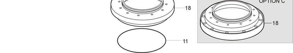
3 Maintenance, Overhaul & Test Instructions Models & Internal/Bottom Loading Valves 1.0 INTRODUCTION This manual furnishes detailed instructions covering the maintenance and overhaul of Eaton s Carter brand Models 64128, and Internal/Bottom Loading Valves. This manual assumes that the valves will be used with a Carter Level Sensor (s); however the 64128A, B, 64118A or B can also be used with optic probe (s) using solenoid valve (s) to affect the control of the pilot valve (s). If so, service manuals for these components should be requested from the manufacturer of the items used. Carter does not provide such items. 2.0 EQUIPMENT DESCRIPTION The Carter family of 6 valves can be used either as a straight internal valve or for bottom loading control. The mounts directly into a 6 TTMA Tank Sump Ring or in the case of the C option it will directly replace the equivalent Whittaker F620. The 64128A is used with the Carter Level Sensor for bottom loading control with a single control pilot valve. Option B adds two-stage level control with two pilot valves. (Note: Early units contained provisions for only single pilot valves with the dual capability available at a later date.) Option B requires either the use of 64079B, C or two Level Sensors. A Carter Vent, 64078, is also available to complete the system requirements. A basic Internal Valve can be converted to a bottom-loading valve, 64128A, by adding a pilot valve. The Bottom Loading Valve is used only for bottom loading. The difference between the and the is the absence of an offloading cylinder on the and a different orifice system in the piston. The units are spring loaded overbalanced piston valves. Fuel inlet pressure is routed to the inside of the piston chamber through a two-staged orifice in the center of the piston. If the piston chamber has no exit, the areas inside the piston chamber (outer diameter of the piston) is larger than the face seal of the piston, hence the balance of pressure forces, plus the spring force will keep the piston (valve) closed. If the piston chamber is vented through an open pilot valve, options A or B, the pressure drop across the inlet orifice reduces the piston chamber pressure significantly. The resultant balance of forces will cause the piston to open. When the piston chamber is once again closed [pilot valve (s) closes], the balance of forces again causes the valve to close. The or A or B is normally utilized with the Level Sensor. If so desired, a solenoid valve (s) can be used in the system to provide or deprive the pilot valve of pressure (usually routed from the bottom loading adapter) to cause the opening and closing of the valve. In this way the valve can be used with either the Civacon Liberty or the Scully Optic Probe Systems. On the 64128, a separate air operated piston is provided to effect off-loading as desired. The direction of air pressure to this piston will cause it to pull open the main piston to allow for off-loading flow. When the air pressure is depleted, the spring forces will close both the air and main pistons. 3.0 AVAILABLE OPTIONS The Basic Valve is designed for use as an internal valve and has no other functional controls. The can be opened for off-loading by application of air pressure to the cylinder provided. The can only be used as option A (64118A) since it has no off-loading capability. The A option (64128A or 64118A) adds a pilot valve to the basic unit making it a bottom loading control valve. Again the 64128A can also be used for off-loading by the application of air pressure to the provided cylinder. The B option (64128B or 64118B) adds two pilot valves to the basic unit to close the valve in twostages. An orifice in the secondary pilot valve will continue to vent the piston chamber after the primary pilot valve has closed. This orifice restricts the pressure escaping from the piston chamber to maintain the piston in a partially open position hence flow into the tank is reduced significantly. This provides a more accurate final shutoff and also helps control surge pressure on final shutoff. A C option is available to interchange the Carter (A or B) with the respective Whittaker F620 Valve. The C option does not have the external (to the tank) air connection potential. It is intended only to replace an existing installation. For new installations it is recommended that the standard A 3
4 or B options be used to allow the use of a standard TTMA Sump Ring. 4.0 DISASSEMBLY 4.1 Refer to Figures 1, 2, 3 or 4 for exploded views of the unit. 4.2 Remove and discard O-Ring (11). 4.3 On (except for option C) remove the Tube Assembly (12). The Fittings (13) can be left in place unless replacement is needed. 4.4 Remove Screws (14) and Screen (15). 4.5 Remove Screws (16) and Washers (17) to remove Adapter Plate (18) being careful on the not to damage the Tube (19) used to route air pressure to the off-loading piston. Discard O-ring (20) and O-ring (21) (on 64128). Remove Tube (19). 4.6 On Unscrew Rod (22). Spring loaded Piston (23) should follow and can be removed along with Spring (26). 4.7 On the Piston (23) with Set Screw (24) and Nut (25) can be removed without removing the Set Screw (24). Spring (26) can also be removed. Do not remove Set Screw (24) or Nut (25) unless damaged. The placement of this screw controls the closing time of the valve. 4.8 Remove the six Screws (27) and Washers (28) from the Bonnet (41) and put a side for reuse. 4.9 Rotate the bonnet slightly in either direction and pull it from the Body (42). Remove and discard O- ring (29). Remove and discard O-Ring (43) and Seal (44) from the body. Continue on with the next paragraph if the unit being disassembled is the Ship to paragraph 4.11 if it is a : Remove Ring (30), Spring Pad (31) and Spring (32). Using the Spring Pin in Shaft Assembly (33) hold the Housing (36) by inserting a suitable drill bit in the hole through the smaller end of the housing unscrew and pull Shaft Assembly (33) from the bonnet. Do not disassemble the Shaft Assembly (33) unless damaged. 5.0 INSPECTION 5.1 It is recommended that all O-rings (11), (20), (21), (29), (37) & (43); Gaskets (4), (7) & 18A; Quad Ring (39); Wipe Ring (38); Diaphragms (48) and Seal (44) be replaced at each overhaul. 5.2 The outer diameters of the Shaft Assembly (33), and Piston (23) along with the inner diameter of Housing (36) should be inspected for scratches that might cause leakage. The piston seat in the Body (42) shall also be free of pits, scratches or gouges that would cause leakage. Inspect all other metal parts for dings, gouges, abrasions, etc. On Remove and discard O-ring (37) using a soft pick that will not damage the bonnet Pull Housing (36) from bonnet. Remove and discard Wipe Ring (38) and Quad Ring (39) Remove Pilot Valves (2) and (5) if present. If a 64128B remove the Orifice (6) and Gasket (7) from the port and discard the gasket. It is not necessary to remove the Plug (3) unless the Gasket (4) is leaking Skip to paragraph : Remove Bonnet (41) Remove Pilot Valves (2) and (5) if present. If a 64118B remove the Orifice (6) and Gasket (7) from the port and discard the gasket. It is not necessary to remove the Plug (3) unless the Gasket (4) is leaking Remove and discard O-ring (43) and Seal (44) from Body (42) Pilot Valve Assy (2) or (5) may be replaced as a complete unit or overhauled as follows: Remove six Screws (45) and Washers (46) Using a thin blade screwdriver, pry the Cover (47) from the assembly. Be careful not to scratch the flanged surface of either metal part holding the diaphragms in place Remove and discard the two Diaphragms (48) Remove Pressure Pad (49) from Poppet (50) shaft Remove Ring (51), which retains Spring (52) and Washer (53) in place. This will free up the remaining parts for removal. all parts except the ones listed above, use 320 grit paper to smooth and remove sharp edges. The outer diameter of the Shaft Assembly (33) and the Piston (23) can be polished to remove minor scratches by using a very fine emery cloth while the parts are rotated. Do not polish local areas of these diameters. Unless proper equipment is available to accomplish this task and to polish the inner diameter of the Housing (36), it is recommended that the parts be replaced. If polishing is attempted, do not break through the hard anodized surface of the Piston (23). If 4
5 scratches are too pronounced, the parts should be replaced. Replace any part with damage exceeding 15% of local wall thickness. Use Aladdin 1200, or similar chem film treatment, to touch up bared aluminum. The flat surfaces of the Fitting (54) and Cover (47) may be polished to remove minor scratches by using a flat plate and very fine emery cloth. Be careful to keep the parts flat during polishing and to not raise any burrs on the inside diameters that bear on the diaphragms. 6.0 REASSEMBLY 6.1 Reassembly is accomplished in essentially the reverse order of disassembly noting the following: Light lubrication of all O-rings and seals, using petroleum jelly is recommended to facilitate installation When reassembling the Pilot Valve Assy (2) or (5) use the following procedure to assure proper diaphragm retention: Once the Poppet (50), Spring (52), Washer (43) and Ring (51) are in place, be sure that the Pressure Pad (49) is placed onto the Poppet (50) shaft with the smaller end placed onto the shaft first. The larger flat surface should be facing away from the shaft The two Diaphragms (48) are placed such that the loops in the diaphragms are facing the Pressure Pad (49). [In operation, the loops always face in the direction in which the pressure from the Level Sensor or solenoid valve is applied.] Smooth out the Diaphragms (48) place onto the Fitting (54) and align the six holes in all three parts. Carefully place the Cover (47) onto this assembly aligning the holes Start the six Screws (45) with the Washers (46) in place by hand until resistance is met. Note that if no resistance is met in attempting to hand tighten the screws, it is recommended that the Screws (45) be replaced. They are self-locking and some resistance should be felt Using Figure 6 mentally number the screws as shown. Using a properly set torque wrench, tighten the number 1 screw to 1.6 in-lbs. (1.8 Kgcm), followed by tightening screws number 5, 3, 6 and 4 in that order. Then repeat the tightening sequence to 3.2 in-lbs. (2.1 Kg-cm) and then 5.3 in-lbs. (6.1 Kg-cm) respectively. Let the assembly stand for a minimum of 15 hours retighten the screws as above to the 5.3 in-lbs. (6.1 Kg-cm) setting When installing the Seal (44) onto O-ring (43) in Body (42) be sure to smooth the surface evenly with a finger. See the installation note on Figures 2 & On the Use Locktite (40) on the thread of Shaft Assembly (33) before screwing on Housing (36). On both units Locktite (40) is used also on Screws (16). Note the thread of both parts should be cleaned with the recommended Locktite cleaning solution prior to using Read the instructions on before using When installing Rod (22) it must be adjusted to provide a gap of ± (.305 ±. 127 mm) between the under side of the hex head of the rod and the mating flat surface of the Piston (23). a feeler gage should be used for this purpose. This will assure that the proper surge control during shutoff will be effective. On the if the Set Screw (24) and Nut (25) were removed it will be necessary to adjust the face of the Set Screw (24) to.409 ±.005 inches ( ±.127 mm) from the face of the Nut (25) If the Screen (15) was removed and replaced, the replacement will be provided in a flat condition and it will be necessary to carefully shape it to fit the Body (42) If Fittings (13) were removed, clean up any existing Teflon tape and replace with no more than 1½ wraps. Since they will be screwed into an aluminum casting more tape may cause the mating part to crack due to excess tape. 7.0 TEST 7.1 The following test procedures will be accomplished after overhaul: 7.2 Test conditions Test media shall be odorless kerosene, Jet A or equivalent at F. 7.3 Functional Test If testing prior to reinstalling the unit in the refueler is desired conduct the following tests: Connect the inlet of the unit to a test media pressure source with a minimum of 150-psig available. Tee off the inlet pressure line to the primary pilot valve and to the secondary pilot valve on B option units. Install a small ball valve between the inlet pressure source and each pilot valve. Install a bleed valve between the pilot valve (s) and the ball valve. Gauges should be installed in the pressure line to the main valve s inlet and in the line to the pilot valve (s). 5
6 7.3.2 On the connect the air port to a 100-psig air pressure source with a gauge in the line Bleed all air from the valve by applying 10-psig test media pressure to the inlet and opening the bleed valve (s) in the lines to the pilot (s). Once the air is bled, close the valve in the line to the pilot (s) and bleed all liquid trapped in the line (s) Increase the pressure to the valve to approximately 25-psig for one minute and then increase it to 150-psig for one minute. Observe for external leakage during the test period. No leakage except from the main piston shall be allowed. This leakage should be limited to 100 cc/minute On the 64128, following the above test with the valve still full of liquid apply air pressure to the unit starting at 35-psig and slowly increasing slowly until the valve opens. The valve should open at an air pressure of 50-psig maximum. If testing the skip this paragraph and go on to Shutoff the air pressure and bleed it to atmosphere. The valve should return to the closed position Apply liquid pressure slowly to the valve inlet and simultaneously to the pilot (s). Observe when the main piston opens. The valve shall open with an inlet pressure of 15-psig or less. 6
7 8.0 ILLUSTRATED PARTS CATALOG Table 1.0 tabulates the parts and sub-assemblies comprising the various versions of both the and Valves with all options. The item numbers of the table are keyed to the exploded views of the unit diagrammed in Figures 1, 2 or 3. Fig. Item Part Number Description TABLE & Bottom Loading Valves & Options Units/ Assy Option Spares/10 Units/Yr Internal Valve, Bottom Loading and Off-loading Internal Valve, Bottom Loading only GF814-10D Plug... 2 Basic - 4 MS Gasket... 2 Basic Pilot Valve, Primary (Figure 4)... 1 A, B & C - 3 GF814-10D Plug... 1 A or AC - GF814-10D Plug... 2 Basic - 4 MS Gasket... 2 Basic, A or AC Pilot Valve, Secondary (Figure 4)... 1 B or BC - 4 MS Gasket... 2 B or BC Orifice... 1 B or BC - 7 MS Gasket... 1 B or BC Left intentionally blank Plate... 1 C - 18A Gasket... 1 C MS O-Ring... 1 All 10
8 FIGURE , & OPTIONS 8
9 Fig. Item Part Number Description TABLE 2.0 Parts Breakdown, Basic Valve Units/ Assy Option Spares/10 Units/Yr MS O-Ring... 1 All Tube assembly... 1 A, B Fitting... 2 A, B A144 Screw... 2 All Screen... 1 All - 16 GF Screw All - 17 GF960C416 Washer All Adapter Plate... 1 A & B Adapter Plate... 1 C - 18A Gasket... 1 C Tube... 1 A & B - 20 MS O-Ring... 1 All MS O-Ring... 2 A & B Rod... 1 All Piston... 1 All Spring... 1 All - 27 GF Screws... 8 All - 28 GF Washers... 8 All - 29 MS O-Ring... 1 All GF Ring... 1 All Spring Pad... 1 All Spring... 1 All Shaft Assembly... 1 All Shaft... 1 All - 35 GF Pin... 1 All Housing... 1 All - 37 MS O-ring... 1 All Wipe Ring... 1 All Q Y Quad Ring... 1 All Locktite... 1 All Bonnet... 1 All Body... 1 All - 43 MS O-ring... 1 All Seal... 1 All 10 9
10 FIGURE PARTS BREAKDOWN 10
11 TABLE 3.0 Parts Breakdown Basic Valve Units/ Spares/10 Fig. Item Part Number Description Assy Option Units/Yr MS O-Ring... 1 All A144 Screw... 2 All Screen... 1 All - 16 GF Screw All - 17 GF960C416 Washer All Adapter Plate... 1 A & B Adapter Plate... 1 C - 18A Gasket... 1 C MS O-Ring... 1 All Piston... 1 All Set Screw... 1 All - 25 GF Nut... 1 All Spring... 1 All - 27 GF Screws... 8 All - 28 GF Washers... 8 All - 29 MS O-Ring... 1 All Locktite... 1 All Bonnet... 1 All Body... 1 All - 43 MS O-ring... 1 All Seal... 1 All 10 11


12 FIGURE PARTS BREAKDOWN 12
13 Fig. Item Part Number Description TABLE 4.0 Pilot Valve Parts Breakdown Units/ Assy Option Spares/10 Units/Yr Pilot Valve Assy, Primary... 1 A, B, AC & BC LP Screw... 6 A, B, AC & BC - 46 GF620C6 Washer... 6 A, B, AC & BC Cover... 1 A, B, AC & BC Diaphragm... 2 A, B, AC & BC Pressure Pad... 1 A, B, AC & BC Poppet... 1 A, B, AC & BC - 51 POL-18 Retaining Ring... 1 A, B, AC & BC Spring... 1 A, B, AC & BC Washer... 1 A, B, AC & BC Fitting... 1 A, B, AC & BC Pilot Valve Assy, Secondary... 1 B or BC LP Screw... 6 B or BC - 46 GF620C6 Washer... 6 B or BC Cover... 1 B or BC Diaphragm... 2 B or BC Pressure Pad... 1 B or BC Poppet... 1 B or BC - 51 GF Ring... 1 B or BC Spring... 1 B or BC Washer... 1 B or BC Fitting... 1 B or BC - KD Kit, seal replacement for 64128A Valve. Contains items 4, 11, 20, 21, 29, 37, 38, 39, & 48. KD Kit, seal replacement for Basic Valve. Contains items 4, 11, 20, 21, 29, 37, 38, 39, 43 & 44. KD Kit, seal replacement for 64128B Valve. Contains items 4, 7, 11, 20, 21, 29, 37, 38, 39, 43, 44 & 48. KD Kit, seal replacement for Pilot Valve Assy. Contains items 4 & 48. KD Kit, seal replacement for 64128AC Valve Assy. Contains items 4, 11, 18A, 20, 29, 37, 38, 39, 43, 44 & 48. KD Kit, seal replacement for 64128BC Valve Assy. Contains items 4, 7, 11, 18A, 20, 29, 37, 38, 39, 43, 44 & 48. KD Kit, seal replacement for 64118A Valve. Contains items 4, 11, 20, 29, 43, 44 & KD Kit, seal replacement for 64118B Valve. Contains items 4, 7, 11, 20, 29, 43, 44 & 48. KD Kit, seal replacement for 64118AC Valve. Contains items 4, 11, 18A, 20, 29, 43, 44 & 48. KD Kit, seal replacement for 64118BC Valve. Contains items 4, 7, 11, 18A, 20, 29, 43, 44 & 48. Notes: 1. All part numbers beginning with "GF" are interchangeable with those beginning with either "AN" or "MS". If three numbers follow the GF it is interchangeable with an "AN" part, otherwise it is interchangeable with an "MS" part of the same number. 2. The recommended spare parts shown above are the number required to support 10 units for one year or each overhaul whichever is sooner. These quantities do not include replacement spares for intermediate replacement of parts required by abuse or misuse of the equipment. The recommended quantities are based on the ratio of spare parts sold for each unit during a one-year period of time. The actual quantity required will vary from location to location. 13
14 FIGURE 4 PILOT VALVE PARTS BREAKDOWN 14
15 FIGURE 5 DIAPHRAGM POSITION PRIOR TO INSTALLING FIGURE 6 DIAPHRAGM TORQUE SEQUENCE 15
16 Eaton Aerospace Group Conveyance Systems Division 9650 Jeronimo Road Irvine, CA Ph (949) Fax (49)
Maintenance & Repair Manual
 SM64055 November 2012 Aerospace Group Conveyance Systems Division Applicable additional manuals: None Carter Brand Ground Fueling Equipment Maintenance & Repair Manual 4 Inch Internal/Bottom Loading Valves
Models & Inch & 4 Inch Digital Inline Pressure Control Valves SM64504
 SM64504 September 2008 Aerospace Group Conveyance Systems Division Carter Brand Ground Fueling Equipment Applicable addition manuals: None Maintenance & Repair Manual 3 Inch & 4 Inch Digital Inline Pressure
3 Inch & 4 Inch Digital Bypass Pressure Control Valves
 SM64505 September 2008 Aerospace Group Conveyance Systems Division Carter Brand Ground Fueling Applicable addition manuals: None Maintenance & Repair Manual 3 Inch & 4 Inch Digital Bypass Pressure Control
3 Inch & 4 Inch Fuel Operated Bypass Pressure Control Valves. Models & 64513
 SM64503 September 2008 Aerospace Group Conveyance Systems Division Carter Brand Ground Fueling Equipment Applicable addition manuals: None Maintenance & Repair Manual 3 Inch & 4 Inch Fuel Operated Bypass
Models & & 4 Air Operated Bypass Pressure Control Valves SM64501
 SM64501 September 2008 Aerospace Group Conveyance Systems Division Carter Brand Ground Fueling Equipment Applicable addition manuals: None Maintenance & Repair Manual 3 & 4 Air Operated Bypass Pressure
Maintenance & Repair Manual. Misc. Male Adapters To Mate Model Nozzles And Model Couplers. SM427MISC June 1, 1993
 SM427MISC June 1, 1993 Aerospace Group Conveyance Systems Divison Carter Brand Ground Fueling Equipment Applicable addition manuals: SM60427 Nozzle SM61445 Coupler SM40679 Quick Disconnect Maintenance
Miscellaneous Male Adapters To Mate Nozzle Models & 64348
 SM428MISC June 1, 1993 Conveyance Systems Division Aerospace Group Carter Brand Ground Fueling Equipment Applicable addition manuals: SM61428 NOZZLE SM64348 NOZZLE Maintenance & Repair Manual Miscellaneous
Bottom Loading & Recirculation Adapters
 SM60373 January 2002 Aerospace Group Conveyance Systems Division Carter Brand Ground Fuelin Equipment Applicable additional manuals: None Maintenance Manual Bottom Loading & Recirculation Adapters Models
Quick Disconnect To Mate Nozzle. Model SM40679 August Applicable additional manuals: SM60427 Nozzle SM Hose End Regulator
 SM40679 August 2009 Aerospace Group Conveyance Systems Division Carter Brand Ground Fueling Equipment Applicable additional manuals: SM60427 Nozzle SM60129-1 Hose End Regulator Maintenance Manual Quick
Non-Valved Unisex Coupling
 SM64019 October 2010 Aerospace Group Conveyance Systems Division Applicable additional manuals: None Carter Brand Ground Fueling Equipment Maintenance Manual Non-Valved Unisex Coupling Model 64019 Model
SM64052 Maintenance & Repair Manual Commercial 2" Unisex Coupling - Valved Model 64052
 Aerospace Group Conveyance Systems Division Carter Brand Ground Fueling Equipment SM64052 July 2004 Applicable additional manuals: SM64051 Commercial 2" Unisex Coupling, Non-Valved Maintenance & Repair
Maintenance Manual. Dry Break Quick Disconnect (Old Style) Model SM November 1, 2011 Applicable additional manuals: SM60427 Nozzle
 Model SM November 1, 2011 Applicable additional manuals: SM60427 Nozzle") Aerospace Group Conveyance Systems Division Carter Brand Ground Fueling Equipment SM60672-1 November 1, 2011 Applicable additional manuals: SM60427 Nozzle Maintenance Manual Dry Break Quick Disconnect
Aerospace Group Conveyance Systems Division Carter Brand Ground Fueling Equipment SM60672-1 November 1, 2011 Applicable additional manuals: SM60427 Nozzle Maintenance Manual Dry Break Quick Disconnect
Model Maintenance Manual. SM44646 October Applicable additional manuals:
 SM44646 October 2009 Aerospace Group Conveyance Systems Division Carter Brand Ground Fueling Equipment Applicable additional manuals: SM61428 NOZZLE SM61429 NOZZLE SM64200 NOZZLE SM64201 NOZZLE SM64348
SM64155 Maintenance & Repair Manual
 SM64155 September 2011 Applicable addition manuals: Aerospace Group Conveyance Systems Division Carter Brand SM61429 Nozzle SM64349 Nozzle SM64201 Nozzle Maintenance & Repair Manual Continuity Dry Break
Swivel Quick Disconnect To Mate Various Carter Brand Nozzles. Model SM Maintenance & Repair Manual
 Aerospace Group Conveyance Systems Division Carter Brand Ground Fueling Equipment SM44315 February 1998 Applicable additional manuals: SM61428 Nozzle SM64348 Nozzle SM64200 Nozzle Maintenance & Repair
Model Maintenance Manual SM July 2011
 SM61154 July 2011 Aerospace Group Conveyance Systems Division Carter Brand Ground Fueling Applicable addition manuals: SM61428 Nozzle SM60427 Nozzle SM64348 Nozzle SM64349 Nozzle SM64200 Nozzle SM64201
Unisex Couplings, Valved. Model Model SM October Applicable additional manuals: None. Maintenance Manual
 SM64020 October 2010 Aerospace Group Conveyance Systems Division Carter Brand Ground Fueling Equipment Applicable additional manuals: None Maintenance Manual Unisex Couplings, Valved Model 64020 Model
SM Pressure Fueling Nozzle Standard Commercial Unit. Model Maintenance Manual
 Eaton Aerospace Business Conveyance Systems Division Carter Ground Fueling Maintenance Manual SM64200 February 2007 APPLICABLE ADDITIONAL MANUALS: SM44315 Quick Disconnect Assy SM44646 Hose End Control
Maintenance Manual 6-INCH INTERNAL VALVE F620 SERIES
 Maintenance Manual 6-INCH INTERNAL VALVE F620 SERIES REVISION 1.1 03/15/2002 LIST OF EFFECTIVE PAGES On a revised page, the portion of text or illustrations affected by the change is indicated by a vertical
7 Emergency Breakaway Fuel Coupling
 SM64191 August 2011 Applicable additional manuals: None Aerospace Group Conveyance Systems Division Carter Ground Fueling Maintenance & Repair Manual 7 Emergency Breakaway Fuel Coupling Model 64191 Table
Maintenance Manual. 4-Inch Internal Valve. F614 Series
 4-Inch Internal Valve F614 Series LIST OF EFFECTIVE PAGES On a revised page, the portion of text or illustrations affected by the change is indicated by a vertical line in the outer margin of the page.
Hydrant Valve In Accordance With Bulletin API Model SM Maintenance & Repair Manual. January 2011
 SM60554 January 2011 Aerospace Group Conveyance Systems Division Applicable addition manuals: SM47076 Carter Brand Ground Fueling Maintenance & Repair Manual Hydrant Valve In Accordance With Bulletin API
Maintenance Manual 4½-INCH INTERNAL VALVE F635 SERIES
 Maintenance Manual 4½-INCH INTERNAL VALVE F635 SERIES REVISION 1.0 11/01/2004 LIST OF EFFECTIVE PAGES On a revised page, the portion of text or illustrations affected by the change is indicated by a vertical
Inline Pressure Control Or Shutoff Valves (Non-digital) And Bypass Pressure Control Or Shutoff Valves (Non-digital)
 And Bypass Pressure Control Or Shutoff Valves (Non-digital)") IN64124 August 15, 1997 Aerospace Group Conveyance Systems Divison Carter Brand Ground Fueling Equipment Applicable additional manuals: Installation Instructions Inline Pressure Control Or Shutoff Valves
IN64124 August 15, 1997 Aerospace Group Conveyance Systems Divison Carter Brand Ground Fueling Equipment Applicable additional manuals: Installation Instructions Inline Pressure Control Or Shutoff Valves
Spring Brake Application
 Technical Tip Maxibrake I Series Spring Brakes Disassembly, Inspections and Reconditioning Instructions Maxibrake I Series spring brake products are mechanical devices and are subject to wear after extended
Maintenance Manual 3-INCH INTERNAL VALVE F660 SERIES
 Maintenance Manual 3-INCH INTERNAL VALVE F660 SERIES REVISION 1.1 03/15/2002 LIST OF EFFECTIVE PAGES On a revised page, the portion of text or illustrations affected by the change is indicated by a vertical
Solenoid Valve Manifold for use with Digital Pressure Control Coupler
 Aerospace Group Conveyance Systems Division Carter Brand Ground Fueling Equipment IN64102 August 1997 Applicable additional manuals: IN64035 Installation Instruction IN64702 Installation Instruction Installation
T60 REGULATOR REPAIR KIT INSTRUCTIONS
 T60 REGULATOR REPAIR KIT INSTRUCTIONS This PPI covers the repair of Series I and II T60 regulators using either a minor or major repair kit. Important: Any maintenance, service or repair should be performed
Maintenance Manual. 3-Inch Internal Valve. F660 Series
 3-Inch Internal Valve F660 Series LIST OF EFFECTIVE PAGES On a revised page, the portion of text or illustrations affected by the change is indicated by a vertical line in the outer margin of the page.
TYPE E Main Valve Sizes 3 /8 through 12
 Technical Data SD 3001E PRINTED IN U.S.A. SD 3001E/9709 SPENCE ENGINEERING COMPANY, INC. 150 COLDENHAM ROAD, WALDEN, NY 12586-2035 A B TYPE E MAIN VALVE FACE TO FACE DIMENSIONS C D E DIMENSIONS (inches)
Digital Manifold with Digital Hydrant Control
 IN64302 December 2008 Aerospace Group Conveyance Systems Division Carter Brand Ground Fueling Equipment Applicable additional manuals: IN64235 IN64108 IN64702 SU64235 Installation Instructions Digital
I & M 8000 Series. Ideal Installation Schematic. Preferred Installation. Trouble Shooting
 I & M 8000 Series 3170 Wasson Road Cincinnati, OH 45209 USA Phone 513-533-5600 Fax 513-871-0105 lowflow@richardsind.com www.lowflowvalve.com Installation & Maintenance Instructions for 8000 Series Low
Steam/Water Washdown Units Safety and Operation Installation and Maintenance Instructions
 INSTALLATION AND MAINTENANCE INSTRUCTIONS IM-8-002-US October 2016 Steam/Water Washdown Units Safety and Operation Installation and Maintenance Instructions These instructions should be read by the Company
MEMORY SEAL BALL VALVES MAINTENANCE MANUAL 2 12, Class 150 & 300, Regular Port, Flanged Unibody
 MEMORY SEAL BALL VALVES MAINTENANCE MANUAL 2 12, Class 150 & 300, Regular Port, Flanged Unibody I INTRODUCTION These rugged, versatile, high performance, regular port, ball valves meet all requirements
Maintenance Manual HOSE END PRESSURE CONTROL VALVE F594 / F595 SERIES
 Maintenance Manual HOSE END PRESSURE CONTROL VALVE F594 / F595 SERIES NOTICE: PROPRIETARY INFORMATION OF WHITTAKER CONTROLS, INC., A BUSINESS UNIT OF MEGGITT PLC. THE INFORMATION CONTAINED IN THIS DOCUMENT
Adjustable Differential Relay A1
 Sales Manual Section 332 PRODUCT SPECIFICATION MODEL 84871-A1 GENERAL DESCRIPTION The 84871-A1 Adjustable Differential Diverting Relay is a two-position, snap-acting, three-way relay. Its normal function
Maintenance Information
 16573370 Edition 2 February 2014 Air Grinder 99V Series Maintenance Information Save These Instructions Product Safety Information WARNING Failure to observe the following warnings, and to avoid these
Char-Lynn Hydraulic Motor. Repair Information Series. April, 1997
 Char-Lynn Hydraulic Motor April, 1997 Repair Information Geroler Motors 002 00 004 Parts Drawing 1 See Note 2 Page 1 22 1 9 1-1/4 Split Flange Ports 8 7 6 5 B 1 See Note 2 Page 2 24 4 14 19 20 15 1 18
KHR Series Regulators
 KHR Series Regulators Maintenance Instructions Kit Contents retainer Poppet Poppet spring Poppet damper Outer body seal Inner body seal Upper piston seal seal backup ring Main piston seal vent seal Self-vent
REFILL STATION REBUILD KIT P/N 14270NOS
 REFILL STATION REBUILD KIT P/N 14270NOS INSTRUCTION SHEET P/N 199R10338 1.0 DISASSEMBLY This procedure describes the removal of the air module from the fluid module and complete disassembly of the pump.
ANDERSON GREENWOOD SERIES 500 PILOT OPERATED SAFETY RELIEF VALVES INSTALLATION AND MAINTENANCE INSTRUCTIONS
 Before installation these instructions must be fully read and understood TABLE OF CONTENTS 1. General valve description and start-up... 1 2. Main valve maintenance... 1 3. Pilot maintenance... 5 4. Pilot
Maintenance Manual BARRIER SERVO ASSEMBLY F1510 SERIES
 Maintenance Manual BARRIER SERVO ASSEMBLY F1510 SERIES NOTICE: PROPRIETARY INFORMATION OF, A BUSINESS UNIT OF MEGGITT PLC. THE INFORMATION CONTAINED IN THIS DOCUMENT IS DISCLOSED IN CONFIDENCE. IT IS THE
MAINTENANCE MANUAL FOR THERMOSTATIC TEMPERATURE REGULATING VALVE TRAC STYLE P
 MANUAL NUMBER P-EFS-1 MAINTENANCE MANUAL FOR THERMOSTATIC TEMPERATURE REGULATING VALVE TRAC STYLE P TRAC Regulator Company Inc. 160 South Terrace Avenue Mount Vernon, New York USA 10550-2408 Phone: (914)
Instructions for INSTALLATION -- OPERATION -- MAINTENANCE of the SELAS AIR/GAS BLENDER VALVE. (for PROPANE/AIR, BUTANE/AIR AND OTHER BLENDS)
") DESCRIPTION The SELAS Blender Valve is a three-port, adjustable area valve which accurately mixes any two of a wide variety of gases. Air and Gas ports in a movable piston are matched to complimentary
DESCRIPTION The SELAS Blender Valve is a three-port, adjustable area valve which accurately mixes any two of a wide variety of gases. Air and Gas ports in a movable piston are matched to complimentary
D-15/G-15 Maintenance
 D-15/G-15 Maintenance NOTE: The numbers in parentheses are the Reference Numbers on the exploded view illustrations found later in this manual and in the Parts Manual. Daily Check the oil level and the
Welker Adjustable Probe with Check Valve and Welker Automatic Insertion Probe with Check Valve
 a Installation, Operation, & Maintenance Manual Welker Adjustable Probe with Check Valve and Welker Automatic Insertion Probe with Check Valve Models AP-3MI & AIP-3MI The information in this manual has
Operation and Maintenance Manual
 Operation and Maintenance Manual MODEL S-216-J-( ) Series AIR-DRIVEN HYDRAULIC PUMP ISSUED NOVEMBER 1994 Revised February 2005 Sprague Products Division of Curtiss-Wright Flow Control Corporation 10195
Maintenance. Daily. Shutdown Procedure. Periodically. During Freezing Temperatures
 Maintenance Daily Check the oil level and the condition of the oil. When the pump is operating, the oil in the pump housing gets warm and expands, filling into the oil reservoir. Depending on the type
Anderson Greenwood Series 800 POSRV Installation and Maintenance Instructions
 Before installation these instructions must be fully read and understood Table of contents 1. General valve description and start-up... 1 2. Main valve maintenance... 2 3. Pilot maintenance... 6 4. Pilot
F-20/G-20 Maintenance
 F-20/G-20 Maintenance NOTE: The numbers in parentheses are the Ref. Nos. on the illustrations in the Parts Manual. Periodically Change the oil after the first 100 hours of operation, and every 1000 operating
Pilot-Operated Regulators
 Fisher Controls Instruction Manual Type 1098-EGR & 1098H-EGR Pilot-Operated Regulators R May 1987 Form 5084 Contents Introduction................................... 2 Scope of Manual..............................
These instructions are applicable to the following models: ARI 1118 ARI 1148
 INSPECTION & MAINTENANCE BULLETIN ARI 1118 & 1148 Safety Relief Valve These instructions are applicable to the following models: ARI 1118 ARI 1148 Only AAR class F facilities are certified to recondition,
0-500 PSI Soft Seat Fluid Pressure Regulator
 Instruction Sheet P/N 0953A Description The Nordson 0-500 psi soft seat fluid pressure regulator is designed for use with nonabrasive liquid coatings. The regulator body is constructed of stainless steel
These instructions are applicable to the following models: ARI 1108 ARI HP1108
 INSPECTION & MAINTENANCE BULLETIN ARI 1108 & HP1108 Safety Relief Valve These instructions are applicable to the following models: ARI 1108 ARI HP1108 Only AAR class F facilities are certified to recondition,
Welker Sampler. Installation, Operation, & Maintenance Manual. Model GSS-4HP
 Installation, Operation, & Maintenance Manual Welker Sampler Model GSS-4HP The information in this manual has been carefully checked for accuracy and is intended to be used as a guide to operations. Correct
Vickers. Overhaul Manual. Vane Pumps. Small and Large Series Combination Pumps VC(K)(S)-**-(*)*D*-6(1) VC(K)(S)-**-(*)-*-*D*-5(1)
(S)-**-(*)*D*-6(1) VC(K)(S)-**-(*)-*-*D*-5(1)") Overhaul Manual Vickers Vane Pumps Small and Large Series Combination Pumps VC(K)(S)-**-(*)*D*-6(1) VC(K)(S)-**-(*)-*-*D*-5(1) Revised 12/1/86 I-3150-S Table of Contents Section I. Introduction................................................................................
Overhaul Manual Vickers Vane Pumps Small and Large Series Combination Pumps VC(K)(S)-**-(*)*D*-6(1) VC(K)(S)-**-(*)-*-*D*-5(1) Revised 12/1/86 I-3150-S Table of Contents Section I. Introduction................................................................................
for ½" thru 2" 800 lb. Piston Lift Check Valves with Resilient Seat Option
 Manual No. 800-PC Issued: March 31, 2004 INSTRUCTION MANUAL for ½" thru 2" 800 lb. Piston Lift Check Valves with Resilient Seat Option Flowserve Corporation Flow Control Division 1900 S. Saunders Street
Maintenance Manual HYDRANT SHUTOFF VALVE F352 / F353 SERIES
 Maintenance Manual HYDRANT SHUTOFF VALVE F352 / F353 SERIES NOTICE: PROPRIETARY INFORMATION OF WHITTAKER CONTROLS, INC., A BUSINESS UNIT OF MEGGITT PLC. THE INFORMATION CONTAINED IN THIS DOCUMENT IS DISCLOSED
Installation Instructions
 Preparing your vehicle to install your brake system upgrade 1. Rack the vehicle. 2. If you don t have a rack, then you must take extra safety precautions. 3. Choose a firmly packed and level ground to
Digital III Fueling Vehicle Control System
 SM64335-2 April 2005 Aerospace Group Conveyance Systems Division Carter Brand Ground Fueling Equipment Applicable additional manuals: SM64335-1 Setup & Calibration User s Manual Digital III Fueling Vehicle
A-320 Balanced 1st Stage
 Technical Manual A-320 Balanced 1st Stage A Manual for Repair and Maintenance Technicians View: Select Full Screen mode to use page arrows. FEATURES Extra durable satin chrome plated brass body. Fully
Digital II Pressure Control Module. Model IN64235 August Installation Instructions. Applicable addition manuals:
 Aerospace Group Conveyance Systems Division Carter Brand Ground Fueling Equipment IN64235 August 2009 Applicable addition manuals: IN64101 IN64108 IN64102 IN64802 SU64235 Installation Instructions Digital
REGULATORS DELTA 4 SECOND STAGE OCEANIC DELTA 4 SERVICE PROCEDURE
 OCEANIC DELTA 4 SERVICE PROCEDURE This Delta 4 Service Procedure conveys a list of components and service procedures that reflect the Delta 4 as it was configured at the time of this writing (2/19/05).
Miniature Soft Seat Fluid Pressure Regulator
 Instruction Sheet P/N 1. Description The Nordson miniature soft seat fluid pressure regulator is designed for use with hydraulic and pneumatic medias. The regulator body and wetted parts are constructed
Anderson Greenwood Series 400 Piston Pilot POPRV Installation and Maintenance Instructions
 Before installation these instructions must be fully read and understood As capacity relief of the system is satisfied, system pressure will begin to decrease. When it does, the pilot will actuate and
INSTRUCTION AND REPAIR MANUAL MODELS 341A, 342A AND 344A 6
 SECTION 6 ITEM 0 DATED JUNE 1998 SUPERSEDES ITEMS 1, 2, DATED MARCH 1992 INSTRUCTION AND REPAIR MANUAL MODELS 1A, 2A AND A 6 NOTE This repair manual is applicable to pump Models 1A, 2A and A. All photos
D 40 ALUMINIUM (CLAMPED)
") www.tablapump.com A COMPLETE RANGE OF AIR DIAPHRAGM PUMPS CONGRATULATIONS ON PURCHASING YOUR NEW TABLA PUMP! IMPORTANT: Please read all the installation and safety information carefully before you start
www.tablapump.com A COMPLETE RANGE OF AIR DIAPHRAGM PUMPS CONGRATULATIONS ON PURCHASING YOUR NEW TABLA PUMP! IMPORTANT: Please read all the installation and safety information carefully before you start
VIS 40 Series Brake Motors Parts and Repair Manual -004
 Parts and Repair Manual -004 Parts Relief Valve Parts Shown Enlarged 2 Shuttle Valve Parts 4 Shown Enlarged 5 3 10 6 8 1 24 11 12 11 9 7 8 6 13 14 16 20 18 17 25 11 30 21 14 11 15 32 26 42 41 29 45 35
OPERATION MANUAL 1 POLYPROPYLENE PUMP DURA-FLO TM AIR DISTRIBUTION SYSTEM
 OPERATION MANUAL 1 POLYPROPYLENE PUMP DURA-FLO TM AIR DISTRIBUTION SYSTEM CAUTIONS - READ FIRST CAUTION: Do not apply compressed air to the exhaust port pump will not function. CAUTION: Do not exceed 82
#8 VENT VALVE with BRANCH PIPE TEE, Part No
 #8 VENT VALVE with BRANCH PIPE TEE, Part No. 579076 JANUARY, 001 Supersedes Issue dated November, 1988 NOTE: The following description and operation is based on this device and its components being new
CLUTCH COMPONENT LOCATION INDEX
 2005 TRANSMISSION Clutch - MX-5 Miata CLUTCH COMPONENT LOCATION INDEX Fig. 1: Identifying Clutch Components GENERAL PROCEDURES (CLUTCH) PRECAUTION Clutch pipe If any clutch pipe has been disconnected anytime
INSTALLATION/OPERATION/MAINTENANCE INSTRUCTIONS FOR ARCHON MODELS WD2010L, WD2010, WD2010H WASHDOWN STATIONS. ARCHON Industries, Inc.
 ARCHON Industries, Inc. Washdown Stations Models WD2010L, WD2010, WD2010H Installation / Operation / Maintenance Instructions 1 This manual has been prepared as an aid and guide for personnel involved
Welker Automatic Insertion Diffusing Probe Model AIP-3DP
 Installation, Operation, and Maintenance Manual Welker Automatic Insertion Diffusing Probe Model AIP-3DP The information in this manual has been carefully checked for accuracy and is intended to be used
Model Maintenance & Repair Manual. 3 x 4 Inch Hydrant Coupler with Pressure Control To Mate Hydrants in Accordance with API Bulletin 1584
 SM64803 June 2014 Aerospace Group Conveyance Systems Division Applicable additional manuals: None Carter Ground Fueling Maintenance & Repair Manual 3 x 4 Inch Hydrant Coupler with Pressure Control To Mate
D/G-10 Maintenance. Daily. Shutdown Procedure During Freezing Temperatures. Periodically
 D/G-10 Maintenance NOTE: The numbers in parentheses are the Reference Numbers on the exploded view illustrations found in this manual and in the Parts Manual. Daily Check oil level and condition of oil.
GH-BETTIS OPERATING & MAINTENANCE INSTRUCTIONS DISASSEMBLY & ASSEMBLY FOR THE T80X-M4-S DOUBLE ACTING SERIES HYDRAULIC ACTUATORS
 GH-BETTIS OPERATING & MAINTENANCE INSTRUCTIONS DISASSEMBLY & ASSEMBLY FOR THE T80X-M4-S DOUBLE ACTING SERIES HYDRAULIC ACTUATORS -S INDICATES CYLINDERS ARE IN TANDEM PART NUMBER: 100121 REVISION "A" ECN
Table of Contents Visual Inspection and Neutralizing... 3 Disassembly
 1 Table of Contents Visual Inspection and Neutralizing... 3 Disassembly... 3... 4... 4 Cleaning... 4 Inspection... 4 Reconditioning of Valve Seats... 5 Lapping Procedures... 5 Lapping Blocks... 5 Lapping
REGULATORS DELTA 3 SECOND STAGE TROUBLE SHOOTING SYMPTOM POSSIBLE CAUSE TREATMENT
 TROUBLE SHOOTING SYMPTOM POSSIBLE CAUSE TREATMENT * Freeflow or leakage present. (ADJUSTMENT KNOB (33) turned in) 1. LEVER ARM (17) bent. 2. Excessive intermediate pressure. 3. Damaged or worn POPPET SEAT
D/G-03 Maintenance. Shutdown Procedure During Freezing Temperatures. Daily. Periodically
 D/G-03 Maintenance NOTE: The numbers in parentheses are the Ref. Nos. on the illustrations in the Parts Manual. Daily Check the oil level and the condition of the oil. The oil level should be 3/4 in. (20
Soft Seat Fluid Pressure Regulator
 Instruction Sheet P/N 04622F Description The Nordson soft seat fluid pressure regulator is designed for use with nonabrasive liquid coatings. The regulator body is constructed of stainless steel with a
Two seal rings will be installed in each piston groove, total of four rings installed in each piston.
 When seals removal is complete, piston grooves will have exposed metal with no seals. Wipe clean piston grooves (towel). Repeat seals removal for second piston. Note: Deteriorated O-rings will be flattened
INSTALLATION INSTRUCTIONS REPAIR SEAL KIT PowerSurvivor 40E
 INSTALLATION INSTRUCTIONS REPAIR SEAL KIT PowerSurvivor 40E PURPOSE OF THE KIT The Repair Seal Kit should be installed after 1000 hours of operation. It should be installed regardless of whether or not
Hard Seat Fluid Pressure Regulator
 Instruction Sheet P/N 04742-02 Description The Nordson hard seat fluid pressure regulator is designed for use with abrasive coatings. The regulator body is constructed of stainless steel with a nickel-plated
Installation, Operation, and Maintenance Manual
 Installation, Operation, and Maintenance Manual Welker Automatic Insertion Heated Regulator High Voltage Model IHRA-4SS-220/230 100 or more inch insertion length The information in this manual has been
REGULATORS ALPHA 8 SECOND STAGE OCEANIC ALPHA 8 SERVICE PROCEDURE
 OCEANIC ALPHA 8 SERVICE PROCEDURE This Alpha 8 Service Procedure conveys a list of components and service procedures that reflect the Alpha 8 as it was configured at the time of this writing (2/19/05).
Transmission Overhaul Procedures-Bench Service
 How to Assemble the Lower Reverse Idler Gear Assembly Special Instructions In 1996 Eaton changed the reverse idler system design. In the nut design, the reverse idler bearing was lubricated through a hole
Maintenance Instructions
 General Note These instructions contain information common to more than one model of Bevel Gear Drive. To simplify reading, similar models have been grouped as follows: GROUP 1 Models 11, 0, 1,, (illustrated),,
ANDERSON GREENWOOD. Before installation these instructions must be fully read and understood.
 ANDERSON GREENWOOD Before installation these instructions must be fully read and understood. 1.1 General The Anderson Greenwood Series 200 Pilot Operated SRV uses the principle of pressurizing the larger
Maintenance Information
 16575128 Edition 2 May 2014 Air Grinder, Sander or Polisher 77A Series Maintenance Information Save These Instructions Product Safety Information Failure to observe the following warnings, and to avoid
Cylinder and Valve: AirHawk II Air Mask
 Cylinder and Valve: AirHawk II Air Mask MAINTENANCE AND REPAIR MSA 011 (L) Rev. 0 MSA 2010 Prnt. Spec. 10000005389(I) Mat. 10104218 Doc. 10104218 Parts List Cylinder Replacement Kits Item P/N Description
Model No. 668D3. COFFEPUMP Part No Product Code: O/C GJAN21.DB6B-DC310B
 Model No. 668D3 COFFEPUMP Part No. 9168 Product Code: O/C GJAN21.DB6B-DC310B OVERHAUL MANUAL with ILLUSTRATED PARTS LIST Page 1 of 15 P/N 5914 Rev D 01/17/05 1.0 Introduction 1.1 Description 1.1.1 The
and 1/4 TURN SECOND STAGE REGULATOR TAL 502 (L) Rev. 0 MSA 2005 Prnt. Spec (I) Mat Doc
 Rev. 0 MSA 2005 Prnt. Spec (I) Mat Doc") and 1/4 TURN SECOND STAGE REGULATOR TAL 502 (L) Rev. 0 MSA 2005 Prnt. Spec. 10000005389 (I) Mat. 10064383 Doc. 10064383 REGULATOR COMPONENTS Item Part No. Description 1 MASK MOUNTED REGULATOR ASSEMBLY
and 1/4 TURN SECOND STAGE REGULATOR TAL 502 (L) Rev. 0 MSA 2005 Prnt. Spec. 10000005389 (I) Mat. 10064383 Doc. 10064383 REGULATOR COMPONENTS Item Part No. Description 1 MASK MOUNTED REGULATOR ASSEMBLY
Maintenance Information
 16573347 Edition 2 February 2014 Air Grinder Series 88H Maintenance Information Save These Instructions Product Safety Information WARNING Failure to observe the following warnings, and to avoid these
SERIES G3DB/AG3DB ELEVATOR
 TM INSTRUCTIONS AND PARTS LIST SERIES G3DB/AG3DB ELEVATOR WARNING This manual, and GENERAL INSTRUCTIONS MANUAL, CA-1, should be read thoroughly prior to pump installation, operation or maintenance. SRM00059
D-04/G-04 Maintenance
 D-04/G-04 Maintenance NOTE: The numbers in parentheses are the Ref. Nos. on the illustrations in the Parts Manual. Daily Check the oil level and the condition of the oil. The oil level should be 1/4 in.
INSTRUCTIONS FOR INSTALLATION, START-UP, AND OPERATION
 30/8.5.1 INSTRUCTIONS FOR INSTALLATION, START-UP, AND OPERATION VKP PILOT OPERATED PRESSURE REDUCING VALVE 12501 Telecom Drive, Tampa, Florida 33637 1. Introduction The Class VKP pilot-controlled steam
OPERATION MANUAL 2 POLYPROPYLENE PUMP DURA-FLO TM AIR DISTRIBUTION SYSTEM
 OPERATION MANUAL 2 POLYPROPYLENE PUMP DURA-FLO TM AIR DISTRIBUTION SYSTEM CAUTIONS - READ FIRST CAUTION: Do not apply compressed air to the exhaust port pump will not function. CAUTION: Do not exceed 82
FOR FUTURE REFERENCE SERIES 93HPS
 Hypro Series 93HPS Hydraulically Driven Wetseal Multistage Pumps Repair Manual KEEP FOR FUTURE REFERENCE Form L-1578R Rev. A SERIES 93HPS Hydraulically Driven Stainless Steel Multistage Centrifugal Pumps
Installation, Operation, and Maintenance Manual. Welker Automatic Insertion Corrosion Coupon Device Model AID-1CC
 Installation, Operation, and Maintenance Manual Welker Automatic Insertion Corrosion Coupon Device Model The information in this manual has been carefully checked for accuracy and is intended to be used
Northern Pump A Division of McNally Industries, LLC
 Northern 4000 Series Pumps REV 0.0 Northern Pump Shaft Seal Replacement Northern Pump A Division of McNally Industries, LLC 340 West Benson Avenue Grantsburg, WI 54840 Toll Free: 1-800-366-1410 Phone: