30140 &30142 F5 Dual Fan Controller
|
|
|
- Lora Scott
- 6 years ago
- Views:
Transcription
1
2

3 2501 Ludelle Street Fort Worth, Texas Phone Fax Sales Tech Web: &30142 F5 Dual Fan Controller Introduction: The F5 Dual Fan Controller can be installed onto most any vehicle with electric radiator cooling fans. These fan controllers, and 30142, are designed to control two brushed 12VDC electric motor cooling fans. The following list of parts, necessary terminals, wire, connectors, mounting hardware and components, are included in this kit. (1) F5 Fan Controller Module with Fan Motor Ground Wires (1) 14 pin header connector with wire harness (1) MIDI fuse holder (1) 70 Amp MIDI fuse (2) #6 x ½ fuse mounting screws (2) #6 nuts for fuse mounting screws (4) 1/4 Heat Shrink (3) 10 gauge #10 ring terminal (1) 10 gauge 5/16 ring terminal (1) 10 gauge 3/8 ring terminal (1) 10 gauge 5/16 ring terminal (1) 10 gauge 1/4 ring terminal (4) 1/4 heat shrink (1) 3/8 star washer (1) 5/16 star washer (1) 1/4 star washer Parts list is continued on next page 1
4 (1) 16 gauge blue1/4 spade terminal (4) 18 gauge pink 1/4 spade terminal (1) SPDT black toggle switch (1) Red push button (1) Rubber grommet (10) 7 Zip Ties (20) 4 Zip Ties (3) #8-1/2 Self Tap Screws (3) Posi-Taps (4) 12 gauge Butt Splices (4) 1/4 heat shrink (3) 20 gauge Butt Splices (3) 3/16 Heat Shrink (2) #10x32 ¾ Black Screws (2) #10x32 Black Nylon Locking Nuts (1) Temperature Sensor (1) Temperature Sensor Adaptor (30140 only) (1) Temperature Sensor Pigtail (4) 3/16 Heat Shrink (1) Installation Schematic 2
5 The following information is HIGHLY CRITICAL to the success of the installation and function of this product. These controllers are have a temperature monitoring system embedded inside the microprocessor on the circuit board that will allow for Painless Performance Products to capture the highest temperature the controller was exposed in the event of a failure. DO NOT MOUNT THIS CONTROLLER IN ANY LOCATION UNDER THE HOOD WITH EXCESSIVE HEAT. On most vehicles, the fender wells are not a good location for this product. However, most vehicles radiator core support will stay cool during operation of the vehicle and serves as a good location to mount the F5 controller. Note: Mounting location is critical to controller life span. There is a high probability of premature failure if mounted in a location with excessive heat. Specifications: The F5 Dual Fan Controller is manufactured to these specifications. Do not operate this controller beyond these specifications. Automotive Spec 125 C / 257 F temperature rating. Mounting location is critical to controller life span. This cooling fan controller is designed to handle temperatures up to 257 F (125 C). This is the standard automotive specification for any product that is considered to be under hood rated. Most areas within the engine compartment of most vehicles do not get this hot. But, some do including areas around exhaust manifolds/headers and piping or areas where air will run off of these components at temperatures upwards of 1500 F. Needless to say if this fan controller is mounted anywhere near engine components that reach this temperature it will fail. We have written into the controls of the fan controller a temperature recording program. It records maximum PCB temperature and can be read back by our engineering department should the module be returned as a failed unit. If you overheat the PCB the warranty is voided. Water must also be kept from flooding the unit within the plastic enclosure. So, when mounting it make sure it s where it won t see water in excess from rain or when washing the vehicle. It is encouraged to mount the controller in an area under the hood such as behind the headlight buckets, on the radiator 3
 control of low side (-) of brushed 12VDC electric motors only.")


6 core support or to one of the front fenders. Any area that does not see an excess of water or heat is fine. Continuous Amperage handling of 35 Amp per fan channel. Startup spike Amperage handling of 70 Amps per fan channel. Pulse Width Modulation (PWM) control of low side (-) of brushed 12VDC electric motors only. Some common Ford Taurus and Lincoln Mark VIII fans will draw in excess of 105 amps at startup. Our controller will handle these fans, but only with our single fan controller kits P/N s and DO NOT run two of the larger mentioned fans with our and kits. Tools Needed: Wire Crimping and Stripping Tools: This style of hand crimper can be purchased from just about any local auto parts store, home improvement store or can also be purchased online. You will need this style of crimper to crimp terminals included in the parts kit. A good set of wire strippers are required. This style of wire stripper is ideal for this Gauge Controller install because of its ability to properly strip wire gauges 10 to 20. These are available from just about any local auto part store, electrical supply shop, home improvement store or can be purchased online. Volt/Ohm Meter: A Volt/Ohm meter is always a good tool to have on hand when installing any type of electrical components into any vehicle. A standard inexpensive volt/ohm meter will work fine for this application. They can be purchased from any home improvement store, local hardware store, electrical supply shop or online. Electric Drill, Drill Bits, and Socket Head Nut drivers: A drill, drill bits and socket head nut drivers will be needed for the installation of the F5 controller, fuse holder, momentary button and toggle switch. A 9/16 drill bit or hole saw will be necessary. Heat Gun: A heat gun will be need to shrink the heat shrink over any butt splice that are made. Hand Tools: Standard hand tools such as a large Philips screwdriver, small Philips screwdriver and ¼ socket set will be required to complete the installation of the F5 fan controller. 4
7 Operation: Once installed into a vehicle this fan controller will pulse width modulate (PWM) the GROUND SIDE of two 12VDC electric cooling fans. With all components included in this kit properly installed you can expect the controller to function as follows: 1. PWM control of cooling fan speed is primarily dictated by three things: a. Signal from thermistor within the coolant sensor is read by the F5 controller. This signal is used to monitor engine coolant temperature. b. The engine coolant temperature at which both cooling fans startup at 50% duty cycle is determined by the user adjustable Start potentiometer located on the side of the controller. The potentiometer is adjusted with a small Phillips screw driver. Adjustments are from 160 F F. WARNING: This potentiometer can easily be damaged. Please see page 13 for more information. c. Temperature at which cooling fans are commanded to 100% duty cycle is determined by the user adjustable Full potentiometer (pot for short) located next to the Start pot. The potentiometer is adjusted with a small Phillips screw driver. Adjustments are from 160 F F. WARNING: This potentiometer can easily be damaged. Please see page 13 for more information. Note: For instance, if the Start pot is set to 190 F and Full pot is set to 210 F the controller will turn the cooling fan on at 50% duty cycle when the temperature sensor reads 190 F. If the engine temperature continues to rise the F5 controller begins to increase the duty cycle of the fan in direct relation to the temperature increase. The amount of change in fan duty cycle per increase of temperature degree is dependent upon how close the Full pot setting is to the Start pot setting. The closer their settings are to the same degree the faster the fan duty cycle will rise from 50% to 100%. 2. Cooling fan speed can also be controlled through the connection and use of secondary overrides. These overrides interrupt the primary fan control. Each override is listed and described below: a. Toggle switch- A three position toggle switch is included in this kit. It is a simple On/Logic/Off toggle switch with three leads on it. Once properly connected it allows the user to manually turn the cooling fans to 100% duty cycle (on), 0% duty cycle (off) or to function normal with the controller in control (logic). Although this toggle switch is considered a secondary override it does in fact override all other functions of the controller. For instance if the toggle switch is put into 5
8 the off position the cooling fans will be commanded to off no matter what. Same can be said for the on position. b. VSS cutoff- This controller can receive a signal from a vehicle speed sensor and use this sine or square wave signal to monitor vehicle speed. Once the push button switch and VSS signal wire are connected and the F5 controller is properly programmed it will shut off the cooling fans at a user defined vehicle speed. The vehicle speed at which fans turn off is set with the push button switch while driving at that speed. When depressed the controller records the VSS signal into its memory. From that point forward the F5 controller will always shut off the cooling fans after the vehicle exceeds this set speed for more than 5 seconds. If the vehicle drops down below the set speed the F5 controller reengages the cooling fans. c. A/C compressor- A/C compressors are engaged with a 12 volt signal from a vehicle s A/C switch. This fan controller can monitor this 12 volt signal. Once the A/C sense wire is properly connected this controller will command the cooling fans to 100% on when the compressor is commanded on by the A/C switch. Note: If the F5 controller should lose signal from the temp sensor it will proceed to operate the cooling fan(s) at 100% duty cycle. It will do so indefinitely until the temp sensor signal is once again readable. The sensor included in this kit is manufactured by Delphi and has been used in the automotive industry for decades. It s very durable and reliable. A loss of signal to the F5 controller is most likely a broken wire, incorrectly installed wire or someone is trying to use a different sensor. Note: If vehicle has the A/C compressor running but is also traveling above the vehicle speed set point the F5 controller will not engage the cooling fan. This is because when a vehicle is traveling at highway speeds the air moving across the A/C condenser should be adequate for the heat transfer required by the condenser and radiator. 6
9 Please refer to the Installation Schematic that is separately printed from this Installation Manual during the process of installing your new F5 controller. Component Installation: 1. Mount the F5 cooling fan module using either two black self-tap hex head screws OR the two black Phillips screws and black nylon lock nuts from the parts kit. If you are using the Phillips screws you will need to mark and drill two 3/16 holes for the screws. Make sure the two 12 gauge black/yellow and black/green PWM wires can reach the ground wires from the cooling fans. Note: Before mounting this fan controller visualize how air will flow through your engine compartment. After the air passes through the radiator it will usually run into the front of your engine first. Then, the air splits to the left, right and down. We suggest you mount this controller away from the areas that are within the direction of travel of this hot air. Inner fenders catch the brunt of this hot air, so we feel this area is not suitable for mounting. However, the core support is usually a suitable place for mounting. NEVER ON THE FAN SHROUD!!! 2. Find a good place to mount the 70 Amp fuse holder. It is suggested to mount this as close to the battery as possible and between the battery and F5 module. Use the two #6 screws and nuts in the same bag with the fuse and fuse holder to mount it. You will need to mark and drill two ¼ holes for the #6 screws. 3. Find a suitable spot in the water jacket of the engine to install the temperature sensor. DO NOT INSTALL THIS INTO THE THERMOSTAT HOUSING. This sensor can also be installed into the lower radiator hose with the proper pipe coupler and 3/8-18 pipe threaded bung (30140) or M threaded bung (30142). (We do not provide the parts to install the sensor into the lower radiator hose.) The threads on the sensor are 3/8-18 NPT for part number and M for part number You will also find a 3/8-18NPT to 1/2-14NPT adapter in the bag with the sensor for part number It is ideal to thread the sensor into the engine head. If you cannot, then install it into the water pump, intake manifold or the lower 7
10 radiator tank. Once installed plug in the adapter pigtail and route the wires over towards the F5 module. 4. Inside the vehicle find a suitable place to mount the toggle switch and push button switch. You will need to mark and drill two ½ holes to mount the toggle switch and push button switch. Keep in mind, when finding a suitable mounting location, that you will need to be able to press the push button while driving to program the VSS cutoff speed. Use the rubber grommet from the parts kit to run the wires through the firewall for the switches. The grommet will require you to drill a 9/16 hole with a drill bit or hole saw. a. The push button switch is only used to set the vehicle speed signal fan cutoff. b. The toggle switch can be used to manually switch the fans between 100% duty cycle (on), 0% duty cycle (off) and logic (controller selects duty cycle based off of coolant temperature, VSS signal and A/C signal) BOTH SWITCHES ARE REQUIRED TO BE INSTALLED FOR ALL VEHICLES REGARDLESS IF YOU PLAN TO USE THE A/C WIRE OR VSS CUTOFF INPUT WIRE. 8


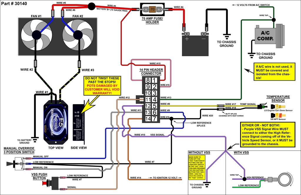
11 Wire Harness Installation: Connect each wire as described in this section. ALL wires must be correctly installed for the F5 controller to function properly. 1. Plug the 14 pin connector into the F5 controller. 2. Wire #1- Black 10 gauge wire protruding from the center slot on the side of the F5 controller. Connect this wire to ground post on the battery. The parts kit has 3/8, 5/16 & 1/4 ring terminals and heat shrink to pick from for use with this connection. There is also three corresponding sized star washers to help make a better ground connection depending on what size ring terminal is chosen to be used. Cut the wire to length and strip off ¼ of insulation. Then slide the heat shrink over the wire and crimp on the ring terminal you have chosen to use. Shrink the heat shrink around the terminal using the heat gun. Make sure to properly crimp all butt splices and terminals when installing this harness. When crimping these terminals, take notice to the split in the terminal. Make sure the smooth side of the jaw on the crimper goes towards this split. *Keep in mind that a bad ground connection is 99% of the time the issue with dealing with electrical problems on automobiles. Take your time and make this a good connection. Clean off any rust or paint from the surface where you make this connection. 3. Wire #2- Black/Green 12 gauge wire protruding from one of the side slots on the side of the F5 controller. Route this wire to the ground wire of cooling fan #1. Cut the wire to length, then strip ¼ of insulation from both the ground wire from the fan and the Black/Green wire. Slide one piece of ¼ heat shrink on to one of the wires, then connect them using one of the 12 gauge butt splices. Shrink the heat shrink over the butt splice using the heat gun. 4. Wire #3- Black/Yellow 12 gauge wire protruding from the other slot on the F5 controller. Route this wire to the ground wire of cooling fan #2. Cut the wire to length, then strip ¼ of insulation from both the ground wire from the fan and the Black/Yellow wire. Slide one piece of ¼ heat shrink on to 9
12 one of the wires, then connect them using one of the 12 gauge butt splices. Shrink the heat shrink over the butt splice using the heat gun. 5. Wire #4- Red 10 gauge wire that is spliced to Wire #5 and #6. A piece of the 10 gauge red wire will be cut and used to be connect one side of the 70 amp fuse to the positive battery post. Cut a piece of the red 10 gauge wire to the appropriate length, then strip ¼ of insulation from both ends of the cut piece of wire. Slide two pieces of ¼ heat shrink over the cut piece of wire then crimp the 5/16 ring terminal on the battery side and a #10 ring terminal on the fuse side. Shrink the heat shrink over the terminals using the heat gun Connect the 5/16 ring terminal to the positive post on the battery and connect the #10 ring terminal to one side of the fuse in the fuse holder. Now take the remainder of the red 10 gauge wire that is still spliced to wire #5 and #6 and strip ¼ of insulation from the end of the red 10 gauge wire. Now terminate this wire and red 20 gauge wire # 15, after cutting wire # 15 to length and striping ¼ of insulation from it, using one #10 10 gauge ring terminal. Be sure to slide one piece of ¼ heat shrink over both wires before crimping the terminal on to both of them. Shrink the heat shrink over the terminal using the heat gun. Connect the #10 ring terminal to the other side of the fuse in the fuse holder. 6. Wire #5- Red 12 gauge wire that is spliced to Wire #4 and #6. Route this wire to the power wire for fan #1. Cut the wire to length, then strip ¼ of insulation from both the power wire from the fan and red 12 gauge wire #5. Slide one piece of ¼ heat shrink on to one of the wires, then connect them using one of the 12 gauge butt splices. Shrink the heat shrink over the butt splice using the heat gun. 7. Wire #6 Red 12 gauge wire that is spliced to Wire #4 and #5. Route this wire to the power wire for fan #2. Cut the wire to length, then strip ¼ of insulation from both the power wire from the fan and red 12 gauge wire #6. Slide one piece of ¼ heat shrink on to one of the wires, then connect them using one of the 12 gauge butt splices. Shrink the heat shrink over the butt splice using the heat gun. 8. Wire #20 Black 20 gauge wire must be spliced to the #18 coming from the temp sensor pigtail. The butt splice is already crimped onto the temp sensor pigtail, slip a piece of the 3/16 heat shrink onto the wire and crimp them together with the butt splice. Shrink the heat shrink over the butt splice using the heat gun. 10

13 9. Wire #8 Yellow 20 gauge wire in pin #5 of the 14 pin connector. This wire is to be connected to yellow Wire #17 from the temp sensor pigtail. The butt splice is already crimped onto the temp sensor pigtail, slip a piece of the 3/16 heat shrink onto the wire and crimp them together with the butt splice. Shrink the heat shrink over the butt splice using the heat gun. 10. Wire #10 Purple 20 gauge wire in pin #12 of the 14 pin connector. This wire is to be connected to the high side or signal wire of the vehicle s speed sensor. Use one of the blue Posi-taps or use one of the supplied gauge butt splices and 3/16 heat shrink from the parts kit to make this connection. Connecting this wire provides the F5 controller a signal from the vehicle s speed sensor. This signal is monitored and used during the VSS fan cut off algorithm. Sine Wave Generators: Vehicle speed sensors that generate an A/C or sine waveform are two wire sensors. If your vehicle has an aftermarket two wire speed sensor connect this wire to the same wire ran to either your fuel injection computer or speedometer. If your vehicle has a factory VSS generator you will need to identify which of the two wires is the high side wire. OEM schematics usually show this as VSS High wires. If you are having issues identifying which wire to connect here call our tech line for assistance at (800) Square Wave Generators: Vehicle speed sensors that generate square waveforms have three wires. These sensor wires are power, ground and signal. Connect the VSS signal wire from the F5 controller to the signal wire from the sensor. If your vehicle has an aftermarket three wire speed sensor connect this wire to the same wire ran to either your fuel injection computer or speedometer. If you are having issues identifying which wire to connect here call our tech line for assistance at (800) Note: If you do not have a VSS and/or do not want to use this optional feature this wire must then be connected to a ground source. Also, to disable the VSS shut off or delete the stored VSS shut off value simply put the toggle switch into manual off mode and push the red button for 3 seconds. Then, put the toggle switch back into the center position (normal mode). 11
14 11. Wire #9 Blue 20 gauge wire in pin #6 of the 14 pin connector. This wire is to be connected to either outside terminal of the toggle switch. Cut this wire to length, then strip off ¼ of insulation. Crimp on one of the pink female spade terminals to make this connection 12. Wire #11 Grey 20 gauge wire in pin #13 of the 14 pin connector. This wire is to be connected to the opposite outside terminal from Wire #9 on the toggle switch. Cut this wire to length, then strip off ¼ of insulation. Crimp on one of the pink female spade terminals to make this connection. 13. Wire #12 Tan 20 gauge wire in pin #11 of the 14 pin connector. This wire is to be connected to the either terminal of the push button switch. Connecting this wire provides a signal to the F5 controller from the push button. When the controller sees the signal that the button is pushed it then captures the signal from the VSS wire and records it to memory for use during the VSS fan cut off algorithm. Cut this wire to length, then strip off ¼ of insulation. Crimp on one of the pink female spade terminals to make this connection. 14. Wire #7 Black 20 gauge wire from pin #7 splice. This wire is going to be terminated at the On/Logic/Off switch. Cut this wire to length and strip ¼ of insulation off. Then strip ¼ of insulation from one side of the left over wire and terminate both pieces of wire with the blue spade terminal. This terminal will be connected to the center spade terminal on the back of the On/Logic/Off. Now terminate the other end of the small piece of black wire by cutting it to length and striping ¼ of insulation off, then crimp one of the red spade terminals to this wire. This terminal will be connected to the other side of the red push button. 15. Wire #13 Green 20 gauge wire in pin #4 of the 14 pin connector. This wire is to be connected to the A/C compressor activation wire. Connecting this wire provides a signal for the F5 controller to command 100% duty cycle to the cooling fans when the A/C compressor is activated. Use one of the blue Posi-taps or use one of the supplied gauge butt splices and 3/16 heat shrink from the parts kit to make this connection. 12
15 16. Wire #14 Orange 20 gauge wire in pin #14 of the 14 pin connector. This wire is to be connected to a FUSED, ignition 12 Volt source. It turns the F5 module on. Use a voltmeter to find an ignition 12 Volt source either in the engine compartment or under the dash. Use one of the blue Posi-taps or gauge butt splices and 3/16 heat shrink from the parts kit to make this connection. DO NOT TWIST THIS WIRE TOGETHER WITH THE RED #15 WIRE AND PUT THEM BOTH ON THE SAME POWER SOURCE. IT WILL NOT WORK!!! 17. Wire #15 Red 20 gauge wire in pin #1 of the 14 pin connector. This wire is to be connected to the same threaded post on the 70 Amp fuse holder along with Wire #4. THIS SHOULD HAVE BEEN CONNECTED IN STEP #4 ON PAGE 9 OF THIS INSTRUCTION MANUAL. 13
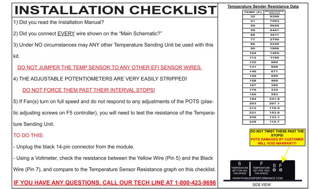
16 F5 Setup: Follow these setup steps to check for proper operation from the F5 controller. NOTE: The potentiometers located on the side of the F5 controller are depicted in the illustration below. Both pots have a movement swing of 270. When using the small Phillips screw driver to move these pots please be careful. The screw driver will turn the pots very easily, if you feel resistance to movement then the pot is most likely turned all the way one way. BE VERY CAREFUL!!! DO NOT OVERTIGHTEN AND STRIP OUT THE START/PULL POTS DURING ADJUSTMENT. THEY ARE ONLY NYLON AND CAN BE DAMAGED EASILY. IF YOU STRIP OUT THE POTS; YOU WILL VOIS YOUR WARRANTY AND RUIN YOUR F5 FAN CONTROLLER. WE WILL NOT WARRANTY THIS PRODUCT BECAUSE OF THIS ABUSE. 1. Turn the vehicle s ignition key on and start the engine. The Start pot is already set to its lowest setting, 160 F. As the engine warms up to 160 F the cooling fans should turn on to 50% duty cycle or roughly half speed. Use a small Phillips screw driver to turn this pot slowly to the right. As you do this you are increasing the start temperature at which the fans are turned on at 50% duty cycle. Turn it to the right until the fans shut off. Now continue 14
17 to turn the pot to the right, let the engine warm up and the fans turn on until the engine is at the temperature you want the fans to run at 50% duty cycle. Make sure you are watching the coolant temperature gauge in your instrument cluster. Note: Once the F5 controller senses the engine temperature has reached its Start pot setting it will operate both cooling fans at 50% duty cycle. A 3 F drop in engine temperature from the Start pot setting will command the F5 controller to shut the fans off. So, if you have the Start pot set where the fans turn on at 200 F, the F5 controller will continue to operate the fans until the engine temperature decreases to 197 F. 2. The Full pot is already set to its highest setting, 235 F. Turning this pot to the left will decrease the temperature at which the F5 controller commands the cooling fans to 100% duty cycle. Your vehicle, its radiator size, engine horsepower and cooling fan size will determine this pots setting. If you set the Full pot setting lower than the Start pot setting the fan will always run at 100% duty cycle once the temperature sensor reaches the Start temperature. Note: A vehicle with cooling fans that are quite large, an efficient radiator installed and good airflow dynamics through the engine compartment may get away with leaving this pot at its highest setting. It will all depend on whether the engine s temperature is maintained properly with the commanded cooling fan speed. If your engine temperature is higher than you like then turn this Full pot to the left. Do so in small increments. 3. With the engine still running turn the A/C compressor to on. If you have elected to connect the A/C compressor sense wire the cooling fans should now be running at 100% duty cycle. Turn the A/C to off. 4. With the engine still running move the toggle switch from the center position (Normal Operation) to either other position. The switch should command the fans to off in one of the positions and to 100% duty cycle in the other. Put the switch back into the normal or center position. It should be left here at all times unless you need to manually turn the fans on or off. Keep in mind that this switch s position overrides all other controls of the cooling fans. If you put the switch into the off position the cooling fans will 15
18 never turn on. If you put the switch into the on position the cooling fans will only turn off if the ignition switch sense wire loses its 12 volt signal by turning the ignition switch to the off position. 5. Now with all the other F5 controller features functioning properly it is time to calibrate the VSS shut off set speed. This is done by driving the vehicle at a speed you would like the fans to not operate above and then pushing the red push button once. At this point the F5 controller captures the VSS signal into its memory. Each time the button is pushed the signal is captured into memory. So, if you set it but don t like the speed at which it was set just drive the vehicle at the new speed and press the button again. We suggest you set your VSS shut off at a speed greater than 35 miles per hour. If you notice your VSS shut off point has changed without you pressing the red button you may be experiencing interference from your A/C compressor clutch. Note: If you notice your VSS shutoff point has changed without you pressing the red button you may be experiencing an interference issue involving you re A/C compressor clutch. If you experience this please contact our tech line at for assistance. Note: If the vehicle is traveling below your VSS shut off speed and then accelerates to a speed greater than the stored VSS value it must continue to travel above the VSS set point value for 5 seconds, before the F5 controller will shut the cooling fan(s) off. Note: If the vehicle is traveling above your VSS shut off speed and then decelerates to a speed less than the stored VSS value the F5 controller will immediately turn the fan on if they are commanded, so by the A/C or coolant temperature sensor. Note: To disable the VSS shut off or delete the stored VSS shut off value simply put the toggle switch into manual off mode and push the red button. Then put the toggle switch back into the center position (normal mode). 16
19 Painless Performance Limited Warranty and Return Policy: Chassis harnesses and fuel injection harnesses are covered under a lifetime warranty. All other products manufactured and/or sold by Painless Performance are warranted to the original purchaser to be free from defects in material and workmanship under normal use. Painless Performance will repair or replace defective products without charge during the first 12 months from the purchase date. No products will be considered for warranty without a copy of the purchase receipt showing the sellers name, address and date of purchase. 17
30140 F5 Dual Fan Controller
 30140 F5 Dual Fan Controller 1 2501 Ludelle Street Fort Worth, Texas 76105 817-244-6212 Phone 817-244-4024 Fax 888-350-6588 Sales 800-423-9696 Tech E-mail: painless@painlessperformance.com Web: www.painlessperformance.com
Trail Rocker Installation
 Trail Rocker Installation Instructions Customizable Trail Rocker Control System For Installing Painless Part Number: 57100 Manual #90616 Painless Performance Products recommends you, the installer, read
Track Rocker Installation Instructions
 Track Rocker Installation Instructions For Installing Painless Part Numbers: 58103: 8-Switch Customizable Track Rocker Switch Panel w/ Flanged Mount 58106: 6-Switch Customizable Track Rocker Switch Panel
Trail Rocker Installation Instructions
 Trail Rocker Installation Instructions Manual #90580 For Installing Painless Part Numbers: 57000 and 57001 Painless Performance Products recommends you, the installer, read this installation manual from
Trail Rocker Installation Instructions
 Trail Rocker Installation Instructions Manual #90581 For Installing Painless Part Numbers: 57002 Painless Performance Products recommends you, the installer, read this installation manual from front to
Trail Rocker Installation
 Trail Rocker Installation Instructions 4, 6, or 8 - Switch Customizable Trail Rocker Switch Panel w/ Flanged Mount For Installing Painless Part Number: 57103, 57106, & 57109 Manual #90636 Painless Performance
Track Rocker Installation Instructions
 Track Rocker Installation Instructions Customizable Track Rocker Control System For Installing Painless Part Number: 58100 Track Rocker Relay Center Manual #90641 Painless Performance Products recommends
Installation Instructions
 Installation Instructions Part #40120 Perfect Performance Products, LLC Painless Performance Products Division 2501 Ludelle Street Fort Worth, TX 76105-1036 800-423-9696 phone 817-244-4024 fax Web Site:
PIN BULKHEAD CONNECTOR KIT
 2501 Ludelle Street Fort Worth, Texas 76105 817-244-6212 Phone 817-244-4024 Fax 888-350-6588 Sales 800-423-9696 Tech E-mail: painless@painlessperformance.com Web: www.painlessperformance.com 40130 22 PIN
Trail Rocker Installation Instructions
 Trail Rocker Installation Instructions Trail Rocker - Genesis Bracket For Installing Painless Part Number: 57200 Manual # 90591 To be used with Painless Kit # s: 57000-57005 Painless Performance Products
Installation Instructions For #64320 Striker Turbo Timer Module
 2501 Ludelle Street Fort Worth, Texas 76105 817-244-6212 Phone 817-244-4024 Fax 888-350-6588 Sales 800-423-9696 Tech E-mail: painless@painlessperformance.com Web: www.painlessperformance.com Installation
Wire Harness Installation Instructions
 Wire Harness Installation Instructions For Installing: Part #50001 Race Car Kit/8 Circuit Part #50201 8 Switch Dash Mounted Panel Part #50202 8 Switch Roll Bar Mounted Panel Manual #90502 Painless Performance
Installation Instructions For #64260 Striker FE Module GMC/Chevrolet Duramax LB7 Diesel Copyright
 Installation Instructions For #64260 Striker FE Module 2001-2004 GMC/Chevrolet Duramax LB7 Diesel 2 nd Edition August 2007 Copyright 2006 by Perfect Performance Products, LLC 2501 Ludelle Street Fort Worth,
Installation Instructions For #64160 Striker II Power Module GMC/Chevrolet Duramax LB7 Diesel Copyright
 Installation Instructions For #64160 Striker II Power Module 2001-2004 GMC/Chevrolet Duramax LB7 Diesel 2 nd Edition August 2007 Copyright 2006 by Perfect Performance Products, LLC 2501 Ludelle Street
Installation Instructions For 50330, 50331, 50332, and Off Road Switch Panels
 Installation Instructions For 50330, 50331, 50332, and 50333 Off Road Switch Panels 2501 Ludelle Street Fort Worth, Texas 76105 817-244-6212 Phone 817-244-4024 Fax 888-350-6588 Sales 800-423-9696 Tech
Installation Instructions For 50340
 Installation Instructions For 50340 2501 Ludelle Street Fort Worth, Texas 76105 817-244-6212 Phone 817-244-4024 Fax 888-350-6588 Sales 800-423-9696 Tech E-mail: painless@painlessperformance.com Web: www.painlessperformance.com
Installation Instructions. Manual # For Installing: Part # Painless Gauge Controller
 Installation Instructions Manual #90579 For Installing: Part #60650- Painless Gauge Controller Perfect Performance Products, LLC Painless Performance Products Division 2501 Ludelle Street Fort Worth, TX
Off-Road Switch Panel Installation Instructions
 Off-Road Switch Panel Installation Instructions 50330: Off-road 4 Toggle switches/dash Mount w/keyed Ignition Switch 50332: Off-road 6 Toggle switches/dash Mount w/keyed Ignition Switch Painless Performance
200-4R TRANSMISSION LOCK-UP HARNESS INSTALLATION INSTRUCTIONS
 2501 Ludelle Street Fort Worth, Texas 76105 817-244-6212 Phone 817-244-4024 Fax 888-350-6588 Sales 800-423-9696 Tech E-mail: painless@painlessperformance.com Web: www.painlessperformance.com 60110 200-4R
HPC Radiator Fan Control Kit
 Revised 07.02.15 www.hpcontrols.ca odels Covered 102002, 102003, 102004, 102005, 102006, 102007 HPC Radiator Fan Control Kit (102005 Shown) The HPC Radiator Fan Control kits provide automatic control over
HPC Radiator Fan Control Kit
 Revised 06.25.14 www.hpcontrols.ca odels Covered 102002, 102003, 102004, 102005 HPC Radiator Fan Control Kit (102002 Shown) The HPC Radiator Fan Controllers provide automatic control over one or more electric
Installation Instructions For #64060 Striker I Power Module GMC/Chevrolet Duramax LB7 Diesel
 2501 Ludelle Street Fort Worth, Texas 76105 817-244-6212 Phone 817-244-4024 Fax 888-350-6588 Sales 800-423-9696 Tech E-mail: painless@painlessperformance.com Web: www.painlessperformance.com Installation
Installation Instructions For #64066 Striker I Power Module Ford Powerstroke 6.0L Diesel Copyright
 Installation Instructions For #64066 Striker I Power Module 2003-2006 Ford Powerstroke 6.0L Diesel 2 nd Edition August 2007 Copyright 2006 by Perfect Performance Products, LLC 2501 Ludelle Street Fort
UNIVERSAL GAUGE WIRE HARNESS
 2650-1797-00 UNIVERSAL GAUGE WIRE HARNESS For Installing Auto Meter Electric Speedometer, Tachometer, And Short Sweep Electric Oil Pressure, Water Temperature, Fuel Level, and Volt Meter Gauges. This harness
Magnetic Door Jamb Switches (Ground Style) Installation Instructions
 Installation Instructions") 2501 Ludelle Street Fort Worth, Texas 76105 817-244-6212 Phone 817-244-4024 Fax 888-350-6588 Sales 800-423-9696 Tech E-mail: painless@painlessperformance.com Web: www.painlessperformance.com 80180 Magnetic
2501 Ludelle Street Fort Worth, Texas 76105 817-244-6212 Phone 817-244-4024 Fax 888-350-6588 Sales 800-423-9696 Tech E-mail: painless@painlessperformance.com Web: www.painlessperformance.com 80180 Magnetic
Installation Instructions For #65005 Striker Cold Shot II 1 st Edition March 2009 Copyright 2009 by Perfect Performance Products, LLC
 2501 Ludelle Street Fort Worth, Texas 76105 817-244-6212 Phone 817-244-4024 Fax 888-350-6588 Sales 800-423-9696 Tech E-mail: painless@painlessperformance.com Web: www.painlessperformance.com Installation
Installation Instructions For #65003 Striker Cold Shot II 1 st Edition March 2009 Copyright 2009 by Perfect Performance Products, LLC 1
 2501 Ludelle Street Fort Worth, Texas 76105 817-244-6212 Phone 817-244-4024 Fax 888-350-6588 Sales 800-423-9696 Tech E-mail: painless@painlessperformance.com Web: www.painlessperformance.com Installation
FAN-PWM-V3. Instructions
 FAN-PWM-V3 Instructions FUSE HOLDER 30 AMP FUSE BOOKLET YELLOW RING CONNECTORS (2) INSTRUCTION INSTRUCTION BOOKLETBOOKLET ITEMS INCLUDED IN KIT INSTRUCTION ITEMS INCLUDED IN KIT ITEMS INCLUDED IN KIT INSTRUCTION
Installation Instructions For #65000 Striker Cold Shot Gasoline 1 st Edition August 2007 Copyright 2007 by Perfect Performance Products, LLC 1
 2501 Ludelle Street Fort Worth, Texas 76105 817-244-6212 Phone 817-244-4024 Fax 888-350-6588 Sales 800-423-9696 Tech E-mail: painless@painlessperformance.com Web: www.painlessperformance.com Installation
Installation Instructions For #63021 Striker Diesel MD Power Modules Dodge 600/610 Cummins 5.9L Diesel Copyright
 2501 Ludelle Street Fort Worth, Texas 76105 817-244-6212 Phone 817-244-4024 Fax 888-350-6588 Sales 800-423-9696 Tech E-mail: painless@painlessperformance.com Web: www.painlessperformance.com Installation
Replace light bulb with the same number bulb as the one removed. White Wire: Connect to +12 Volt Lighting
 INSTALLATION INSTRUCTIONS SHORT SWEEP ELECTRIC GAUGES 2650-1079-00 Rev. C CAUTION FOR ALL GAUGE INSTALLATION (AMMETERS EXCLUDED) As a safety precaution, the +12V wire attached to the positive I (+) terminal
Installation Instructions #63000 Striker Diesel MD Power Module Chevrolet Duramax 6.6L Diesel
 2501 Ludelle Street Fort Worth, Texas 76105 817-244-6212 Phone 817-244-4024 Fax 888-350-6588 Sales 800-423-9696 Tech E-mail: painless@painlessperformance.com Web: www.painlessperformance.com Installation
DODGE RAM 24V 5.9L CUMMINS
 DODGE RAM 24V 5.9L CUMMINS DODGE RAM 24V 5.9L CUMMINS TABLE OF CONTENTS SECTION 1 Preparing the Installation 1 SECTION 2 Boost Gauge Installation 2 SECTION Pyrometer/EGT Gauge Installation 4 SECTION 4
20 CIRCUIT ATO FUSE CENTER INSTALLATION INSTRUCTIONS
 2501 Ludelle Street Fort Worth, Texas 76105 817-244-6212 phone 817-244-4024 fax 800-423-9696 Tech E-Mail: painless@painlessperformance.com Web: www.painlessperformance.com 30003 20 CIRCUIT ATO FUSE CENTER
C FORD F250 / F L POWERSTROKE DIESEL WITH AUTOMATIC TRANSMISSIONS ONLY
 EXHAUST BRAKES C40019 1999-2003 FORD F250 / F350 7.3L POWERSTROKE DIESEL WITH AUTOMATIC TRANSMISSIONS ONLY Getting Started Thank you and congratulations on your purchase of a Pacbrake exhaust retarder.
Replace light bulb with the same number bulb as the one removed. White Wire: Connect to +12 Volt Lighting
 INSTALLATION INSTRUCTIONS SHORT SWEEP ELECTRIC GAUGES 2650-1079-00 Rev. C CAUTION FOR ALL GAUGE INSTALLATION (AMMETERS EXCLUDED) As a safety precaution, the +12V wire attached to the positive I (+) terminal
R53 BOOST GAUGE INSTALL
 R53 BOOST GAUGE INSTALL 052009 Thank you for purchasing the ALTA Performance gauge pod. Installation should only be performed by persons experienced in the proper operation of Mini electrical and body
INSTALLATION GUIDE Chevrolet Monte Carlo Dash Panel Part Number: DP9002 Year Series:
 Made in America Lifetime Guarantee Thank you for purchasing this instrument from Intellitronix. We value our customers! INSTALLATION GUIDE Chevrolet Monte Carlo Dash Panel Part Number: DP9002 Year Series:
GM ALLISON 6 SPEED LCT-1000/2000/2400 CO-PILOT Parts list
 2006-10 GM ALLISON 6 SPEED LCT-1000/2000/2400 CO-PILOT Parts list Co-Pilot Computer (1) 601-800-4308 Solenoid Block (1) 601-109-4308 External Wiring Harness (1) 601-011-4308 Internal Wiring Harness (1)
Ford Mustang V6 OEM-Style Fog Light Kit Parts List: Quantity: Tool List:
 2015-2017 Ford Mustang V6 OEM-Style Fog Light Kit Parts List: Quantity: Tool List: LED Foglights/ Bezels 2 Flat head & Phillips screwdriver (if you ordered part#3600) Ratchet & Socket set OR Wiring harness
INSTALLATION INSTRUCTIONS MECHANICAL GAUGES
 1062650-1966-77 MECHANICAL GAUGES QUESTIONS: If after completely reading these instructions you have questions regarding the operation or installation of your instrument(s), please contact Hardin Marine
Wire Harness Installation Manual # Part # 60617
 Wire Harness Installation Manual #90572 For Installing: Part # 60617 26 Circuit/7 Relay 4.8L-6.0 L w/4l60e Integrated Harnesses Perfect Performance Products, LLC Painless Performance Products Division
Xtreme Air Command. Step 1 Prepare the components. Step 2 Select a mounting location. Parts list
 2549 60 90 400 600 30 200 120 800 psi 1000 kpa PSI 0 150 Xtreme Air Command Installation instructions Congratulations on your purchase of a new Xtreme Air Command kit. This kit was designed to provide
30107 & PACK & 6-PACK RELAY BANK
 30107 & 30108 2501 Ludelle Street Fort Worth, Texas 76105 817-244-6212 Phone 817-244-4024 Fax 888-350-6588 Sales 800-423-9696 Tech E-mail: painless@painlessperformance.com Web: www.painlessperformance.com
Installation Instructions. Part #65100
 Installation Instructions Part #65100 Perfect Performance Products, LLC Painless Performance Products Division 2501 Ludelle Street Fort Worth, TX 76105-1036 800-423-9696 phone 817-244-4024 fax Web Site:
SP Switch Programmable Switch Panel Power System. Parts Included
 SP8100 8-Switch Programmable Switch Panel Power System Parts Included 1 Switch Panel 1 100 amp Power Module 1 Power Module Harness 1 Power Module Mounting Plate 1 Battery Cable w/100a MIDI fuse (Littlefuse
3 in 1 TRAIL CHARGER with LOCKOUT
 Owner s Manual P/N: 283821 500 3 in 1 TRAIL CHARGER with LOCKOUT 283821 01 Version 2.04 07/05/2011 Owners Manual Operation Installation Wiring Diagram Troubleshooting Parts Breakdown 1 GENERAL OPERATION
Dodge Cummins Positive Air Shutoff
 1 INSTALL MANUAL 2010-2012 6.7 Dodge Cummins Positive Air Shutoff P/N# 1036722 P/N# 1036722-M UPLEASE READ ALL INSTRUCTIONS BEFORE INSTALLATION An Information decal has been provided in this kit. This
Turn Signal Kit Installation Instructions for Model A Fords & Other Antique Vehicles
 Turn Signal Kit Installation Instructions for Model A Fords & Other Antique Vehicles Lifetime Technical Support support@logolites.com 770-476-7322 www.logolites.com Manual 100-0005N Thank you for purchasing
INSTALLATION AND USER MANUAL
 INSTALLATION AND USER MANUAL SDKIT-730 & SDKIT-734 100% Bolt-On 150 PSI Train Horn System for 2011-2015 F-250 & F-350 Super Duty P/N SDKIT-730 P/N SDKIT-734 Thank you for purchasing a Kleinn Air Horns
Stay-IN-Play with Panic Stop Braking
 INSTALLATION INSTRUCTIONS TOWED VEHICLE BRAKING SYSTEM Stay-IN-Play with Panic Stop Braking SMI Manufacturing, Inc. P.O. Box 14040 Evansville, IN 47728 1-800-893-3763 www.smibrake.com SIP0906 Model SIP0603
ISIS Power Manual and Installation Guide Race Car Replicas- Superlite Coupe
 ISIS Power Manual and Installation Guide Race Car Replicas- Superlite Coupe Table of Contents Overview... 2 System Details... 3 Kit Includes... 3 Technical Specifications... 3 Harness Descriptions... 4
INSTALLATION INSTRUCTIONS
 COLD AIR INTAKE INSTALLATION INSTRUCTIONS PART NUMBER D760-0390C APPLICATION: 1999-2003 E39 M5 PARTS LIST 1 Left Aluminum Intake Tube 1 Air Pump Bracket (A) 1 Right Aluminum Intake Tube 1 Air Pump Bracket
PART # US Patent
 Please read these instructions completely before beginning installation KIT CONTNTS QTY. DSCRIPTION 1 PWM Fan Controller 1 PWM Cover 3 #8 Lock Washers 2 #6 Lock Washers 3 #8 Nuts 2 #6 Nuts 2 Allen Head
It is strongly recommended that this product be installed by a professional.
 Lower bumper Ford raptor Lower Bumper 20" E-Series or SR-Series or 4" E-Series set mounting instructions For Part # s 40133 & 40134 Thank you for purchasing Rigid Industries products for your Ford. Installation
Classic Instruments. Belera. Installation Manual
 Classic Instruments Belera Installation Manual Table of Contents Welcome from the Team at Classic Instruments!... 3 Optional Gear Indicator Mounting... 4 Gauge Mounting... 6 Gauge Cluster Wiring... 8 Gauge
90558 Installation Manual For # Cummins 5.9L Common Rail Diesel
 2501 Ludelle Street Fort Worth, Texas 76105 817-244-6212 Phone 817-244-4024 Fax 888-350-6588 Sales 800-423-9696 Tech E-mail: painless@painlessperformance.com Web: www.painlessperformance.com 90558 Installation
AIR CONTROL ACCESSORY KIT
 RAPID RESPONSE SYSTEM 2283 AIR CONTROL ACCESSORY KIT INSTALLATION INSTRUCTIONS Congratulations on your purchase of a new Air Control Accessory Kit. This kit was designed to provide inflation control of
Instruction Part #90577
 Phantom Key Push Button Ignition System Instruction Part #90577 For Installing: Part # s 55000, 55001, 55002, 55003, 55004, & 55005 Perfect Performance Products, LLC Painless Performance Products Division
C40008 & C40009 EXHAUST BRAKES
 EXHAUST BRAKES C40008 & C40009 1995 2003 Ford F250 / F350 7.3 L Powerstroke Diesel with manual transmissions 1995 1998 Ford F250 / F350 7.3 L Powerstroke Diesel with automatic transmission* *Requires the
Turn Signal / Horn Kit PN 7101 by All years Polaris RZR 1000 and RZR 900, 900-4, 900 trail, 900S and 900XC STOP - THIS KIT IS DESIGNED
 All years Polaris RZR 1000 and 1000-4 2015 RZR 900, 900-4, 900 trail, 900S and 900XC STOP - THIS KIT IS DESIGNED SPECIFICALLY FOR ALL YEAR AND MODEL POLARIS RZR 1000 AND 1000-4. ALSO THE 2015 POLARIS RZR
MICROPROCESSOR-CONTROLLED ENGINES
 INSTALLATION INSTRUCTIONS The manufacturer produces a full line of gauges with many different styles. 1-1/2" Gauges 2 Gauges 2-5/8" Gauges INSTALLATION & SAFETY PRECAUTIONS 1. Read the entire instructions
Wire Harness Installation Instructions Manual #90571 PART 1 For Installing: #10309 Basic Customizable Nostalgia All Black Chassis Harness 17 Circuit
 Wire Harness Installation Instructions Manual #90571 PART 1 For Installing: #10309 Basic Customizable Nostalgia All Black Chassis Harness 17 Circuit Painless Performance Products recommends you, the installer,
Change the and later A/C & Heat system on the Discovery coach With the multi-zone coleman mach thermostat
 Change the 2001.5 and later A/C & Heat system on the Discovery coach With the multi-zone coleman mach thermostat This schematic and wiring diagram is to be used only for single stage heating and single
Installing the Throttle Commander Ford F250 F550 Super Duty
 Installing the Throttle Commander Ford F250 F550 Super Duty 7.3L Power Stroke Diesel 1996 up to 2001.25 T500011 and T500028 1.0 Preparing for Installation...5 2.0 Installing the Throttle Controller...5
Installation Manual for Dodge 24V Cummins Version 3.1. Please read all instructions before the installation of the ATS Co-Pilot
 10/1/12 601-900-2218-INST Installation Manual for 1998.5-2002 Dodge 24V Cummins Version 3.1 Please read all instructions before the installation of the ATS Co-Pilot Thank you for purchasing the ATS Co-Pilot
TRAIL CHARGER with EXTENDER and COMBO NOSE BOX
 TRAIL CHARGER with EXTENDER and COMBO NOSE BOX 284424 01 Version 1.02 03/14/2011 Owners Manual Operation Installation Wiring Diagram Troubleshooting Parts Breakdown 1 GENERAL OPERATION PROBLEM On applications
Dfuser T/C Lock Override with LED
 Dfuser T/C Lock Override with LED the bug that has no cure For more information visit our website at: http://www.dfuser.com Page 1 of 7 User Guide This harness overrides and monitors Torque Converter (T/C)
Superlift TruSpeed Speed Sensor Calibrator For Most Ford Trucks and SUVs 1992-Present INSTALLATION INSTRUCTIONS
 FORM #33001.06-121703 PRINTED IN U.S.A. PAGE 1 OF 11 INTRODUCTION Superlift TruSpeed Speed Sensor Calibrator For Most Ford Trucks and SUVs 1992-Present INSTALLATION INSTRUCTIONS SUPERLIFT SUSPENSION SYSTEMS
HARNESS KIT 3 PORT ISOLATION MODULE LIGHT SYSTEM. Parts List and Installation Instructions CAUTION
 May 1, 2018 Lit. No. 92991, Rev. 00 HARNESS KIT 3 PORT ISOLATION MODULE LIGHT SYSTEM Parts List and Installation Instructions Read this document before installing the snowplow. See your sales outlet/website
Camaro Camaro
 Important facts about this kit. 1. The dash panel used in this picture is used by permission of Covan's Classic. We Make Wiring Easy! 2. This kit requires some modification to your original under dash
INSTALLATION INSTRUCTIONS
 #52180C3 Corvette Radiator & Fan Kits #52181C3 Fits 1968-1972 Fits 1970-1982 Chevrolet Corvette C3 Note: Manual transmission preferred; automatic transmission requires a remote cooler. (pt. #4116C3 available)
INSTALLATION GUIDE Chevrolet Digital Dash Panel Part Number: DP6003 Year Series:
 INSTALLATION GUIDE Chevrolet Digital Dash Panel Part Number: DP6003 Year Series: 1967-1972 * Disconnect the battery before attempting any electrical work on your vehicle. * KIT COMPONENTS One (1) Digital
Ford 7.3L Powerstroke Positive Air Shutoff
 24 October 2012 Ford 7.3L 1999.5-2003 Positive Air Shutoff 1 1999.5-2003 Ford 7.3L Powerstroke Positive Air Shutoff P/N# 1036700 P/N# 1036700-M UPLEASE READ ALL INSTRUCTIONS BEFORE INSTALLATION 24 October
Part # GM LS2, 3 & 7-95mm Throttle Body
 Part # 65303 2006-2011 GM LS2, 3 & 7-95mm Throttle Body Perfect Performance Products, LLC 2501 Ludelle St. Fort Worth, Texas 76105 (800) 423-9696 1 We are always concerned about any corrections or improvements
WirelessONE. Kit INSTALLATION GUIDE. Key Fob Activated Compressor System
 Kit 25870 Key Fob Activated Compressor System MN-751 (041202) ECR 7260 INSTALLATION GUIDE For maximum effectiveness and safety, please read these instructions completely before proceeding with installation.
MCL-3000 SERIES AIR PRESSURE PART# MCL-3K-A
 MCL-3000 SERIES AIR PRESSURE PART# MCL-3K-A Thank you for purchasing the Dakota Digital MCL-3K-A gauge for your Harley Davidson Touring bike. This gauge is designed to be a direct, plug in replacement
INSTALLATION CONSTELLATION DRIVING LIGHTS 5009
 INSTALLATION CONSTELLATION DRIVING LIGHTS 5009 PARTS INCLUDED 1 Right Driving Light with Turn Signals 1 Left Driving Light with Turn Signals 1 Installation Component Kit Including: 8 Insulated Male Spades
TABLE OF CONTENTS INTRODUCTION 3. INSTALLATION PROCEDURES Air Conditioner Location 4. A/C Ducting Installation 5
 585474 1 TABLE OF CONTENTS SECTION PAGE INTRODUCTION 3 INSTALLATION PROCEDURES Air Conditioner Location 4 Air Conditioner Mounting 4 A/C Ducting Installation 5 Power Kit Installation (Batteries). 5 Separator...
Generation III Stand Alone Engine Harness
 78 Rattler Curry Road, Columbia, KY 42728 Phone 1-888-467-4491 sales@bp-automotive.com www.bp-automotive.com Generation III Stand Alone Engine Harness Installation Guide At BP Automotive we take pride
3-5 Hours Professional installation recommended
 INSTALLATION GUIDE APPLICATION LENGTH MODEL YR PART # Nissan Titan / Titan XD - Crew Cab 72 2016-2018 76120-01A Nissan Titan / Titan XD - King Cab 62 2017-2018 76120-01A Nissan Titan / Titan XD - Single
CUMMINS 6.7L EXHAUST BRAKE PRXB EXHAUST BRAKE KIT FOR 2007½-2015 TRUCKS EQUIPPED WITH 6.7L CUMMINS ISB DIESEL ENGINES. C Kit C Kit
 CUMMINS 6.7L EXHAUST BRAKE PRXB EXHAUST BRAKE KIT FOR 2007½-2015 TRUCKS EQUIPPED WITH 6.7L CUMMINS ISB DIESEL ENGINES C44038 4 Kit C44039 5 Kit BEFORE STARTING THE INSTALLATION please read the entire installation
Dodge Cummins Positive Air Shutoff
 1998-2002 24V 5.9 Dodge Cummins Positive Air Shutoff (I-00181) 1 INSTALL MANUAL 1998.5-2002 5.9 Dodge Cummins Positive Air Shutoff P/N# 1036719 P/N# 1036719-M UPLEASE READ ALL INSTRUCTIONS BEFORE INSTALLATION
Installation Tips for your Remote Start system (for RS4LX>GMBP for GM vehicles)
") Installation Tips for your Remote Start system (for RS4LX>GMBP for GM vehicles) Thank you for purchasing your remote start from MyPushcart.com - an industry leader in providing remote starts to doit-yourself
Installation Tips for your Remote Start system (for RS4LX>GMBP for GM vehicles) Thank you for purchasing your remote start from MyPushcart.com - an industry leader in providing remote starts to doit-yourself
Electromotive Tec GT Installation Supplement for the Porsche
 Electromotive Tec GT Installation Supplement for the Porsche 928 1987-95 Copyright 2009 928 Motorsports, LLC. all rights reserved Toll-Free Tech Hot Line: 877-FOR-928M 877-367-9286 Please do not copy this
I N S T A L L A T I O N G U I D E. Ford Transit - Single Sided A (All slider and barn door models)
") I N S T A L L A T I O N G U I D E APPLICATION MODEL YR PART # Ford Transit - Single Sided 2014-2017 76159-01A (All slider and barn door models) INSTALLATION TIME 3-5 Hours Professional installation recommended
I N S T A L L A T I O N G U I D E APPLICATION MODEL YR PART # Ford Transit - Single Sided 2014-2017 76159-01A (All slider and barn door models) INSTALLATION TIME 3-5 Hours Professional installation recommended
In This DIY We Will Show You How To Install Recon Backup Lamps (part # To Run On A Separate Switch & In Reverse.
 In This DIY We Will Show You How To Install Recon Backup Lamps (part # 264150 To Run On A Separate Switch & In Reverse. Please Note, There Are Many Ways of Installing These Lights, Including Wiring Methods,
Dfuser T/C Lock-Un Lock
 Dfuser T/C Lock-Un Lock Performance Diesel and more! For more information visit our website at: http://www.dfuser.com Page 1 of 6 User Guide This harness overrides and monitors Torque Converter (T/C) lockup
& 76 CHEVROLET NOVA HEATER ONLY
 specializing in AIR CONDITIONING, PARTS AND SYSTEMS for your classic hi l PERFECT FIT IN-DASH HEAT/ COOL/ DEFROST 1969-74 & 76 CHEVROLET NOVA HEATER ONLY CONTROL & OPERATING INSTRUCTIONS The controls on
SFGH-100SC SIREN & LIGHT SYSTEM Installation & Operation
 SFGH-100SC SIREN & LIGHT SYSTEM Installation & Operation Rev.7/15 The SFGH-100SC is a precision built, full function 100-watt siren system that incorporates both an alternating headlight and brake light
Installation Tips for your Crimestopper/ProStart Remote Start system (add-on for GM vehicles) v1.02 updated 1/16/2013
 v1.02 updated 1/16/2013") Installation Tips for your Crimestopper/ProStart Remote Start system (add-on for GM vehicles) v1.02 updated 1/16/2013 Thank you for purchasing your remote start from MyPushcart.com - an industry leader
Installation Tips for your Crimestopper/ProStart Remote Start system (add-on for GM vehicles) v1.02 updated 1/16/2013 Thank you for purchasing your remote start from MyPushcart.com - an industry leader
Toggle Button Kit. Installation Instructions MK5 / MK6 Golf, MK5 Jetta
 Toggle Button Kit Installation Instructions MK5 / MK6 Golf, MK5 Jetta Thank you for choosing the Double Apex Toggle Button kit. If you have any questions about the installation please do not hesitate to
Water in Fuel Sensor Kit
 03/08/2016 1050355-1050356 Water in Fuel Sensor Kit (I-00369) 1 Water in Fuel Sensor Kit Fast and Accurate Detection of Water in Diesel Fuel 1050355 Universal Kit For use with BD FlowMax water separator
Installation Instructions for Lingenfelter GM 2500 Suburban & Yukon XL Auxiliary Fan System (with AC clutch controlled fan output)
") Installation Instructions for Lingenfelter 2007-2013 GM 2500 Suburban & Yukon XL Auxiliary Fan System (with AC clutch controlled fan output) PN L300080607 Revision - 1.1 Lingenfelter Performance Engineering
Installation Instructions for Lingenfelter 2007-2013 GM 2500 Suburban & Yukon XL Auxiliary Fan System (with AC clutch controlled fan output) PN L300080607 Revision - 1.1 Lingenfelter Performance Engineering
Ford 6.7L Installation of the Guardian Safety System
 Ford 6.7L Installation of the Guardian Safety System Diesel Tech Industries Ltd. 14215-120 Avenue Edmonton, Alberta, Canada T5L 2R8 Phone: (780) 455-9876 info@dtiguardian.com www.dtiguardian.com DTI05-02.01/13
ONBOARD AIR SYSTEM FOR ALL VEHICLES APPLICATIONS
 ONBOARD SYSTEM FOR ALL VEHICLES APPLICATIONS Thank you and congratulations on the purchase of a Pacbrake onboard air system. Please read the manual prior to starting to ensure you can complete the installation
INSTALLATION INSTRUCTIONS HIGH OUTPUT 2 SPEED RAD FAN ASSEMBLY
 INSTALLATION INSTRUCTIONS HIGH OUTPUT 2 SPD RAD FAN ASSMBLY PART # 66818, 66819, 66820, 66821, 66822, 66823, 66827 & 66828 Please read these instructions completely before beginning installation FAN SHROUD
FREEDOM FILL AUXILIARY SYSTEM Gauge & Switch Console
 2018 Aluminum Tank & Tank Accessories, Inc. 2702-B N. Nichols, Fort Worth, TX 76106 800-773-3047 * 817-378-8455 www.attatank.com attatank@gmail.com FREEDOM FILL AUXILIARY SYSTEM Gauge & Switch Console
Shotgun Double Barrel HPFP install guide
 Shotgun Double Barrel HPFP install guide Thank you for your purchase of the VTT Shotgun Double Barrel HPFP upgrade! First thing to do when you open your box is to make sure all parts are in their respective
COLD WEATHER START KIT Platinum Mini Split
 COLD WEATHER START KIT Platinum Mini Split Cold Weather Start Kit: To be used in conjunction with Platinum Mini Split cooling system. The Coolest Thing In Wine Storage LASS.MPS 051515 Conforms to ANSI/UL