Left Hand Drive (non i-eloop) Installation guide for BBR Turbocharger Conversion Mazda MX-5/Miata ND 2.0L 2015 on
|
|
|
- Emil Carroll
- 6 years ago
- Views:
Transcription


1 Left Hand Drive (non i-eloop) Installation guide for BBR Turbocharger Conversion Mazda MX-5/Miata ND 2.0L 2015 on Contents Introduction... 2 Tools and parts... 2 Required:... 2 Optional:... 2 Torque settings:... 3 Software Installation... 4 Mechanical installation... 4 Data logging... 9 Installation diagrams MX-5 ND turbocharger guide v1.0 Page 1
2 Introduction Congratulations on your BBR turbo conversion purchase, which will transform the performance of your Mazda! Please follow this guide to ensure a hassle free installation. Should you have any queries relating to any part of the installation, please contact your distributor who would be happy to help! Before attempting turbocharged installation please ensure that your vehicle is in its very best possible mechanical condition and has been serviced in accordance to Mazda s schedules. If your car is misfiring or has any mechanical problems, such as a worn or slipping clutch, a turbo installation will only make them worse! BBR advises using only super unleaded (98 octane +) in Europe, or premium (91 octane +) in the US. Lower octane will only result in lower performance! Before starting the disassembly process, we recommend that you pressure wash the engine bay - a clean working environment is far nicer. We have made the installation of this conversion as simple as possible. No drilling or cutting of body work etc required except for trimming of the under shield/wheel arch liners and the original intake scoop to allow intercooler pipe and BBR intake clearance. All BBR components are fitted based on removing and replacing the original part. Rather than listing every single procedure, nut and bolt size and having an installation manual the size of a bible, this guide is intended to provide the necessary instructions for a simple installation without any nannying. It is expected that the installer will not be picking up a hand tool for the first time and be capable of jacking up, raising and supporting their vehicle in the correct and safe manner. Please note that this is the first version of this installation guide and we will be updating this as required. Should you notice anything missing or inaccurate, please let us know as it will help with future DIY installations. Tools and parts BBR recommends the following tools and parts for Mazda MX-5 ND turbo installation. Required: Battery type group 51 US (identical dimensions and capacity as standard battery, with terminals reversed) Metric spanner/wrench set 8-19mm 2 x 27mm spanners or large adjustable spanners Metric socket set and extensions T25 Torx socket Screw driver set Metric Allen keys Side cutters Pliers Sharp Stanley knife Jack and 4 x axle stands (ramp preferred) Spray can of cleaning solvent/brake cleaner and clean rags WD40 or similar spray lubricant Thread sealant 2 x Suitable clean containers to catch and refill engine oil and coolant Optional: Engine oil 5/10-40W Antifreeze Oil filter MX-5 ND turbocharger guide v1.0 Page 2
3 Torque settings: All required torque settings will be added to this guide promptly. MX-5 ND turbocharger guide v1.0 Page 3

4 Software Installation Before any disassembly or starting the installation of your BBR MX-5 turbo it is crucial that you have received your base BBR turbo ROM file. Otherwise, BBR or your distributor will not be held responsible for you not being able to use your vehicle. On receipt of your conversion please follow the instructions within your EcuTek cable package, download and install EcuTek ProEcu from the link provided. 1. To receive your base BBR turbo ROM file, your ECU version and dongle ID are required. Please follow the instructions below and send a clear screen shot to your distributor (making sure both dongle ID and ECU version are legible): With your vehicle s ignition on, engine not running and the OBD cable plugged in to the vehicles diagnostic port which is located under the steering wheel: Open ProEcu, select Tools, Detect Vehicle..., Program Engine ECU. In the new opened window, select Enter Utility Mode, take a screen shot of this window and the main tool bar, turn the vehicles ignition off and close ProEcu. Example screen shot as below: 2. Once your BBR turbo base ROM file has been received and you are ready to perform the mechanical installation, position the vehicle in the desired position and program your BBR ROM, please note that your vehicle can no longer be driven without completing the turbo installation. Follow the same procedures and from the same programming window as above, select Choose ROM File, open the BBR ROM received, select Enter Utility Mode, Program Ecu, and then follow the onscreen instructions. Note: if your vehicle does not already have an EcuTek license you must first go to Help, EcuTek Update. Your license is then applied by selecting Options, Apply License Update and opening the downloaded license. Mechanical installation Instead of repeatedly raising and lowering the vehicle, this section covers disassembly and installation at the same time. It follows the same procedure BBR technicians would install this conversion on site. Read through this guide and familiarise yourself with the procedures outlined fully, before starting the disassembly of your MX-5. Starting from underneath the bonnet: 1. Remove the strut top braces, battery (disconnecting negative terminal first), battery tray, air intake pipe, air box and coolant cap (Fig1). MX-5 ND turbocharger guide v1.0 Page 4
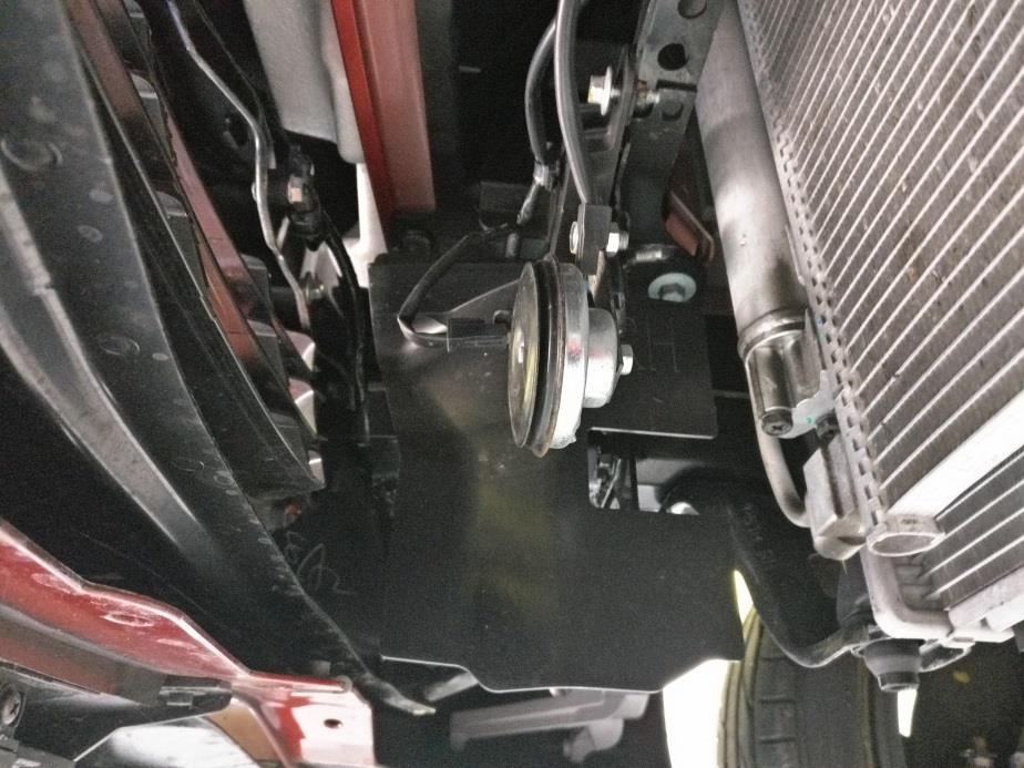
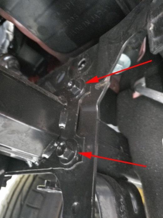
5 2. Remove ABS ECU and bracket, remove the bracket from the ABS ECU, and cut and discard the now unused section with a cutting disc or hacksaw (Fig2). Bend the bracket as shown and install the bracket with the M6 nylon spacer, nylock and flange bolt from bag6. Secure wiring neatly with the supplied cable tie (Fig3). Raise the vehicle and from underneath: 3. Remove all under shields, braces, the front portion of wheel arch liners and then disconnect the exhaust centre section lambda plug and remove the exhaust centre section (Fig4). 4. Remove the exhaust manifold support bracket, and unplug and carefully remove the primary lambda sensor this is delicate and will be reused (Fig5). 5. Remove the horn in front of the radiator with its bracket, remove the right hand side horn and install both in the existing right hand horn position. Note that the wire support clip supporting the wire to the radiator horn would need to be removed (Fig6&7). 6. Remove both air deflectors (2x bolts on each) (Fig8), and the two inner most chassis leg extension bolts from either side (Fig9). 7. Fit the BBR intercooler re-using the 2x chassis leg extension bolts on either side (Fig10). 8. Into a clean container undo the radiator drain and drain the coolant (this can be re-used). Once all coolant has drained re-tighten the radiator drain (Fig11). 9. Use WD40 or similar to install all silicone couplers and aluminium pipes in to the couplers as they are extremely tight and the lubricant will allow easier installation and positioning. Install the 90 degree 57mm silicone coupler to the intercooler outlet (intake engine side) and the 57mm curled aluminium pipe. A 50-70mm hose clamp is used on both sides; position the pipe as shown in Fig12 and Fig13. To ensure that the aluminium intercooler pipe does not rub or touch on the bottom water hose, it is recommended that the bottom water hose is shortened by 10mm on the radiator connection and positioned away from the intercooler pipe. 10. Remove oil pressure sensor and from bag 3 install the oil pressure switch adaptor, turbo oil supply line adaptor and re-install the oil pressure sensor using a suitable thread sealant. Position the adaptor so that the turbo oil supply line will clear the thermostat housing (Fig14) and remove the engine mount nut (shown removed Fig16). Lower the vehicle and continue work under the bonnet: 11. Install the 57mm humped coupler hose to the curly aluminium intercooler pipe using a 50-70mm hose clamp (Fig13) and remove the battery negative terminal supporting clip from the side of the fuse box. 12. Remove both of the heater matrix hoses/pipes that connect to the bulkhead. The steel pipe requires removing completely; leave the rubber heater hose connected to the engine following removal of the steel hard pipe and its bracket. Re-use the rubber mount/supporting bracket for the air condition pipe as shown with steel hard pipe bracket bolt. Please refer to Fig Place a jack under the sump and carefully (with a flat jack top or hard wood packer) raise the exhaust manifold side of the engine 20-30mm (this will aid exhaust manifold removal) and remove the exhaust manifold heatshield (Fig15). MX-5 ND turbocharger guide v1.0 Page 5
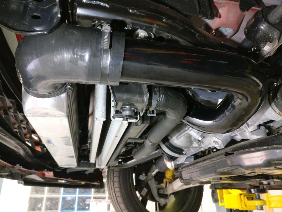
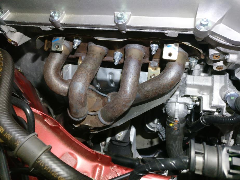
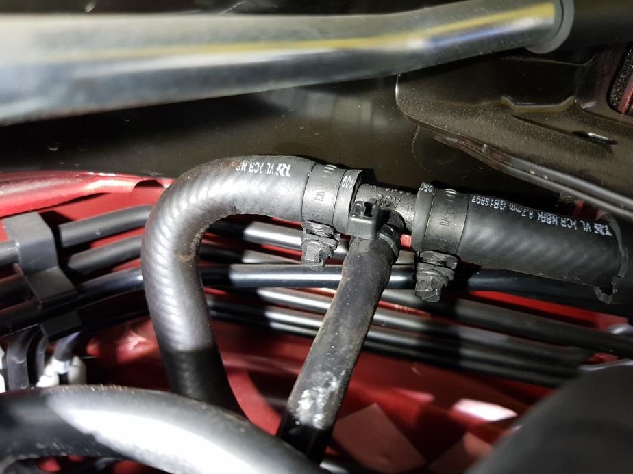
6 14. Remove the exhaust manifold and the centre most exhaust manifold stud. From bag 4 install one of the nine M10 studs (shorter finer threaded M10x1.25 end) into cylinder head (Fig16). We recommend locking two M10x1.5 nuts together to avoid thread damage for all stud removal and installation (use the downpipe to centre section nuts for this). 15. On a suitable bench, install the remaining 8 studs to the turbine housing inlet and outlet (Fig17). From bag 5, install the oil drain adaptor with gasket and the two M6 pan head Allen bolts. From bag 3, install the straight end of the oil drain hose to the turbocharger, ensuring that the 90 degree outlet points straight towards the head face (Fig18). 16. Using the supplied gasket and four M10 stainless locking nuts (bag 4) install the turbocharger to the BBR cast manifold. Please note that due to clearance, the inside (closer to head) nuts must be started first. 17. Install the turbocharger and manifold assembly to the cylinder head (re-using the original exhaust manifold to the head gasket) guiding the oil drain hose towards the sump plug drain. Due to clearance, the central manifold to cylinder head nut must be installed first using the copper locking nut supplied in bag 4. In all other positions, re-use the original manifold to head nuts. Tighten the manifold to head nuts evenly from the centre outwards (Fig19). 18. Within the silicone coupler bag there are three lengths of heat reflective tape. With brake cleaner or similar, clean the existing small heat shield covering the brake pipes and fix the three lengths of heat reflective tape on top (Fig20). 19. Lower the jack on to the rubber engine mount ensuring that the stud is in the correct position, remove the jack and reinstall the engine mount nut. Using the gasket and remaining four stainless M10 locknuts install and tighten the downpipe to the turbocharger. Note that it is far easier to feed the downpipe into position and on to the turbo studs from underneath (Fig19). 20. Install the turbo outlet pipe using the sealing O-ring and two M8 pan head Allen bolts from bag 4 (Fig21). 21. Using 2x M14 banjo bolts and 4x M14 copper sealing washers (bag 4) install the 2x stainless steel turbo water hoses (bag 3) to the turbo, see Fig22 for routing. Using original hose clamp, install the 270mm x 17mm heater hose to the lower heater matrix pipe on the bulkhead. Route the 17mm hose neatly underneath the A/C pipe to join again to the heater hose at the front of the engine (where original hard steel water pipe was previously removed). Using a metal T-piece and length of 8mm heater hose (bag 3) along with 2x 8-16mm and 2x 20-32mm hose clamps, join the inside (closest to engine) stainless turbo water hose and re-join the heater matrix hose. Note: it will be necessary to neatly trim the supplied 8mm and 17mm hoses to the correct length using a Stanley knife, routing the stainless turbo water hose away from the turbine housing and exhaust manifold (Fig22). 22. Fit the 63mm straight silicone coupler to the turbo inlet with a 60-80mm hose clamp. Re-fit the original heater matrix to water pump hose to the lower heater matrix pipe on the bulkhead and trim as shown (Fig22). Fit the supplied 19mm 90 degree water hose (bag 6) to the heater matrix water pump outlet with original hose clamp. Re-join the heater matrix/water pump 19mm hose, using the remaining metal T-piece and with the length of 8mm heater hose the outside stainless turbo water hose (bag 3). Join the hoses with 2x 8-16mm and 2x 20-32mm hose clamps. Note: it will be necessary to neatly trim the supplied 8mm and MX-5 ND turbocharger guide v1.0 Page 6
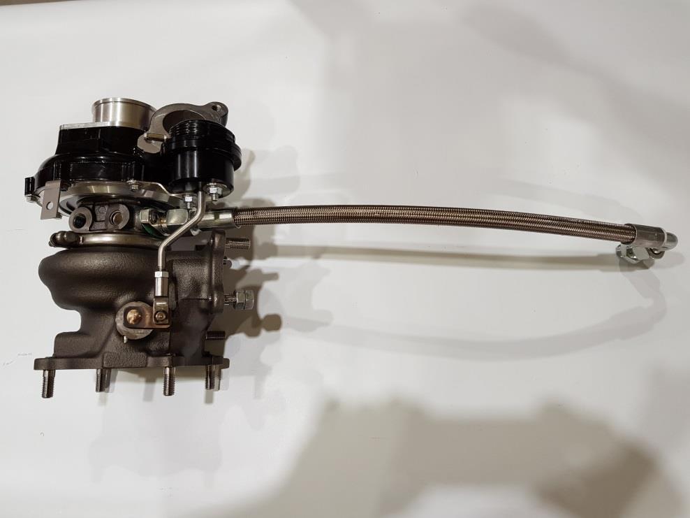
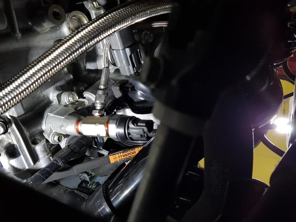
7 19mm 90 degree hoses to the correct length using a Stanley knife, again routing the stainless turbo water hose away from the turbine housing and exhaust manifold (Fig22). 23. This step is not mandatory, however is recommended to aid clearance for the new air filter. Using a Stanley knife trim the intake pipe (removal from vehicle is not necessary) to remove the 10mm larger diameter lip (Fig23). 24. Remove the mass air flow meter (MAF) from original air box lid and reusing the screws to install it to the BBR 180 degree MAF pipe. The O-ring will require sliding up the MAF meter as it will now be sealing on the base (not inside the bore as previous) (Fig24). 25. From bag 5, install the 3 hole flat stainless steel mounting bracket to the filter and M6 rubber mount with flanged nylock to the mounting bracket. With the 70mm straight silicone coupler and 2x 60-80mm hose clamps join the 180 degree MAF pipe to the filter (largest side). On the other side of the MAF pipe install the 63mm hump hose with 1 x 60-80mm hose clamp. For now, leave all the hose clamps loose (Fig24). 26. Move the inner most earth strap on top of the outside earth strap and with the spare bolt install the 2 hole L-shape mounting bracket as shown in Fig The air filter and MAF assembly can now be installed, with a 60-80mm hose clamp (leave loose) install the aluminium turbo inlet pipe to the turbo inlet. The MAF pipe rubber mounting stud slots into the previously installed L-shape bracket and is fixed with the remaining M6 nylock flange nut (bag 5). The 63mm humped hose connects to the aluminium turbo intake pipe with a 60-80mm hose clamp. Before any hose clamp or nut tightening, position the air filter so that it will not rub on the radiator or fan wires, position the MAF meter so that it has sufficient clearance from the radiator expansion bottle, and position the aluminium intake pipe so that it will not rub on the top radiator hose. Once the intake assembly is positioned correctly and square, tighten the M6 nylock and the 5 hose clamps. Note that the hose clamps to the MAF pipe must not be over tightened (just nip these clamps) as over tightening will crush and damage the MAF pipe (Fig27). 28. Install the battery tray (bag 2) using the 2x M8 countersunk Allen bolts and 12mm spacer (Fig13) as shown in Fig28. Place the battery in position (not supplied) and routing the earth strap neatly behind the clamp, fix the battery with the supplied U-bolts, clamps, nuts and washers (Fig29). 29. Install the straight reducing coupler to the throttle body with a 60-80mm hose clamp and the throttle body to intercooler aluminium pipe using 2x 50-70mm hose clamps. Position this pipe carefully allowing plenty of clearance from the top of the battery and ensuring that the curly aluminium hose is not being pushed into the side of the battery or bottom water hose (Fig29). 30. From bag 6, install the recirculating dump valve with 4x 20-32mm hose clamps and the 2x lengths of straight 25mm silicone hose. Using a Stanley knife neatly cut the inlet manifold to brake servo vacuum hose, install the 10x6x10mm plastic T-piece and route the silicone vacuum pipe neatly to the dump valve (Fig30). 31. Replace the OEM manifold absolute pressure (MAP) sensor with the BBR MAP sensor from bag 5. This is a tricky procedure due to the MAP sensor location. It is located at the rear of the manifold and secured with a T25 Torx bolt (Fig31). MX-5 ND turbocharger guide v1.0 Page 7
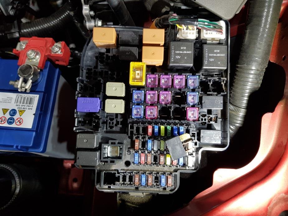
8 32. With extreme use we have found the unsecured PCV/breather hose to disconnect from the underneath of the inlet manifold. Whilst it is difficult to access, please install the supplied spring clip (bag5) to the PCV/breather manifold hose connection (Fig38). 33. From bag 3, install the breather to intake 10mm hose with 2x 8-16mm hose clamps and supporting P-clip. With the M12 banjo and 2x M12 copper washers, install the turbo oil feed line routing towards the oil pressure switch adaptor away from both the turbine housing and actuator rod (Fig32). Raise the vehicle and from underneath: 34. Join the turbo oil supply line to the oil supply line adaptor (Fig33), install the primary lambda sensor to the down pipe (connect to vehicle loom) and re-using original manifold support bracket and bolts, Install the support bracket to the downpipe (Fig34). 35. Re-install the exhaust centre section, fixing it to the downpipe with the supplied M10 nuts and bolts, reusing the copper sealing ring. This can be kept in place in the centre section with exhaust paste or grease while joining to downpipe (Fig35). Please note: US cars with emissions monitoring intact will need to install a new post-cat centre section O2 bung. All US ROM files will have emissions monitoring fully intact unless specifically requested otherwise. 36. Fit the final intercooler pipe. Use a 90 degree 57-51mm reducing silicone coupler on the inlet side of intercooler with a 50-70mm hose clamp. Use a 90 degree 51mm silicone coupler with a 40-60mm hose clamp on the turbo outlet pipe, and then install the 45 degree 51mm aluminium pipe with 2x 40-60mm hose clamps. Position this pipe away from the hard plastic water hose and the power steering motor (Fig36). 37. Remove the sump plug and drain the oil (into a clean container should you wish to re-use the oil). From bag 3 install the oil drain adaptor with a M14 copper washer to the sump, supporting this adaptor attach and tighten the oil drain line to the sump adaptor (Fig37). At this point, before re-fitting the under shields and the turbo heat shield we would recommend running the engine up to temperature and visually inspect to confirm there is no oil or water leaks. Lower the vehicle: 38. Re-fill the engine coolant from the water outlet filler neck until it is close to the top of the water outlet filler neck. Fill the coolant reserve tank up to the FULL mark on the tank. Refill the previously drained engine oil, or if using new oil fill 4.1 litres without filter, 4.3 litres with filter. 39. Install the battery terminals (positive first); remove the fuse box lid and central most fuel injector main relay (Fig39). For oil pressure and to fill the turbo oil supply line, crank the engine for 20 seconds, this is done with the normal start procedure, release the clutch pedal to end engine cranking. 40. Reinstall the injector relay and fuse box lid, and check the oil and coolant level. To prevent any cooling system air locks (with the cooling system cap still removed) start the engine. Turn on the heater (full heat) to the windscreen and run the engine at 2,500 rpm for approximately 5 minutes. Once hot air has been expelled from the heater for a couple of minutes allow the vehicle to idle and install the cooling system cap. Maintain the engine speed at 3,000 rpm for approximately 5 minutes, and then while the engine is idling check for any coolant or oil leaks. Turn off the engine and address any leaks should they be present. MX-5 ND turbocharger guide v1.0 Page 8
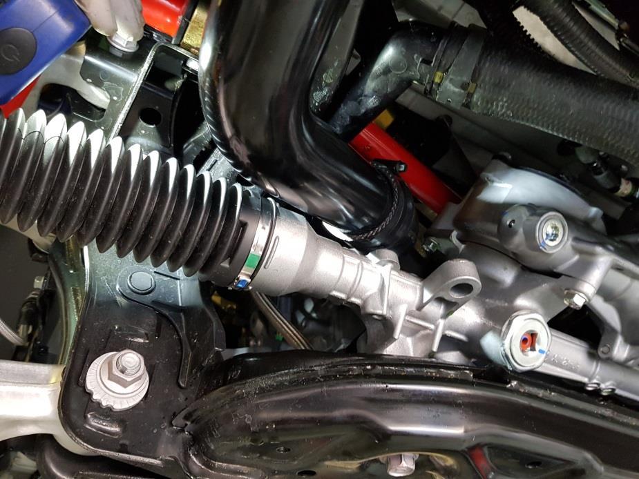
. 42.")
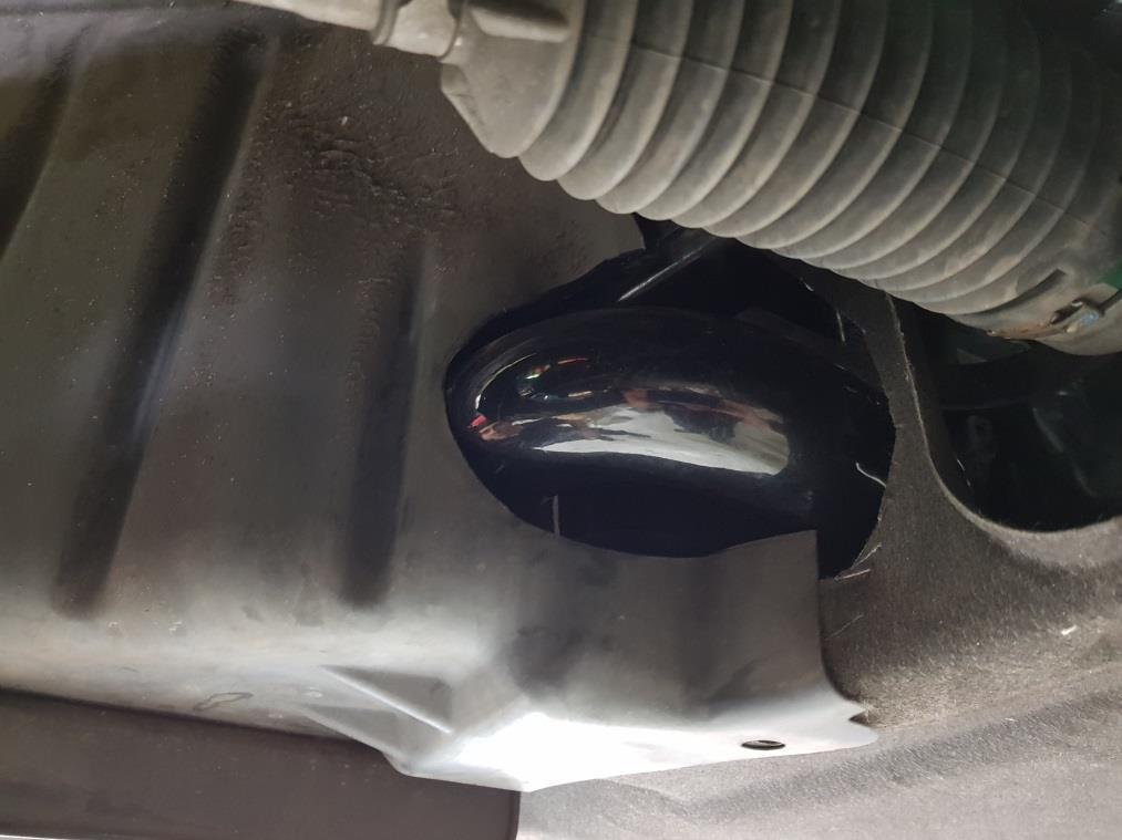
9 Raise the vehicle for the last time: 41. Refit all previous removed under shields, braces and the front portion of wheel arch liners with original fixings. The main under tray and wheel arch liners will require neatly trimming to clear the intercooler pipe work (Fig40,41,42). 42. Lower the vehicle and with a cool turbo/exhaust system install the turbo heat shield. Remove the 4 cam cover bolts and the M6 flange bolt from the turbo compressor heat shield bracket. Hold the shield loosely in place and partly install the M6 flange bolt. Start the 4 cam cover bolts, tighten and then tighten the M6 flange bolt. Note when installing the shield to ensure that the heat tape does not catch on the cam cover and sits on top to the cam cover mated to the shield. 43. To finish all mechanical work, re-install the strut braces with original fixings. Data logging Open ProEcu on the main tool bar select Open ROM File and open the BBR ROM file previously installed.. With the engine running and cable installed to the vehicles OBD port, select Map Access this will show the live data, then select Log to File to begin and end logging (Fig xx). We require a log showing idle, part throttle running and a full throttle log in 3 rd gear or higher, from RPM. When performing the full throttle log it is imperative that AFR Actual, Knock Retard and Manifold Absolute Pressure are closely monitored. Should the AFR value be above 12.5, MAP above 1.5 or knock retard have values lower than -2, lift off immediately! The same goes should there be any audible detonation, unusual mechanical sounds or hesitancy/misfiring. Log files can be opened by selecting File, Open Log File on the main ProEcu menu. The Log files can also be copied and pasted from the file opening window. Please submit the log file (or files) to your distributor and refrain from further full throttle/high load driving until you receive correspondence from your distributor. MX-5 ND turbocharger guide v1.0 Page 9
10 This concludes the BBR Turbo installation guide for Mazda MX-5 2.0L ND models. We hope that you have enjoyed your installation and that your turbocharged BBR MX-5 gives you many years of pleasure and surpasses your expectations. Welcome to the fast lane Remainder of page left intentionally blank for notes: MX-5 ND turbocharger guide v1.0 Page 10


11 Installation diagrams Figure 1 Figure 2 Figure 3 MX-5 ND turbocharger guide v1.0 Page 11


12 Figure 4 Figure 5 Figure 6 MX-5 ND turbocharger guide v1.0 Page 12


13 Figure 7 Figure 8 Figure 9 MX-5 ND turbocharger guide v1.0 Page 13


14 Figure 10 Figure 11 Figure 12 MX-5 ND turbocharger guide v1.0 Page 14


15 Figure 13 Figure 14 Figure 15 MX-5 ND turbocharger guide v1.0 Page 15


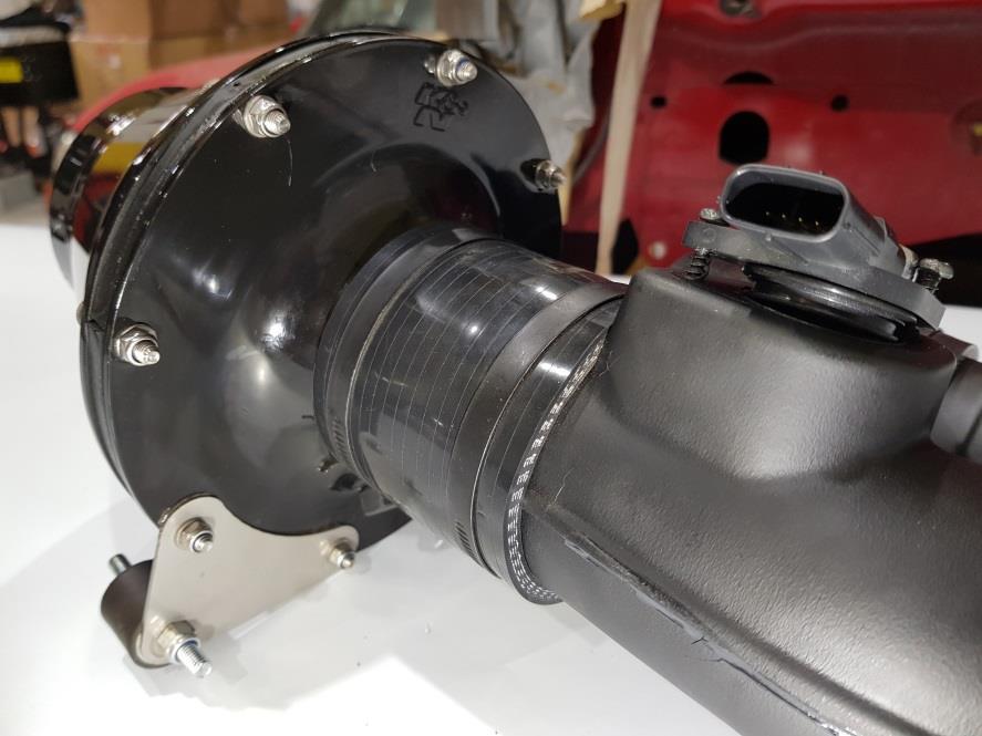
16 Figure 16 Figure 17 Figure 18 MX-5 ND turbocharger guide v1.0 Page 16


17 Figure 19 Figure 20 Figure 21 MX-5 ND turbocharger guide v1.0 Page 17


18 Figure 22 Figure 23 Figure 24 MX-5 ND turbocharger guide v1.0 Page 18


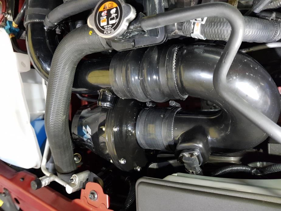
19 Figure 25 Figure 26 Figure 27 MX-5 ND turbocharger guide v1.0 Page 19


20 Figure 28 Figure 29 Figure 30 MX-5 ND turbocharger guide v1.0 Page 20


21 Figure 31 Figure 32 Figure 33 MX-5 ND turbocharger guide v1.0 Page 21


22 Figure 34 Figure 35 Figure 36 MX-5 ND turbocharger guide v1.0 Page 22


23 Figure 37 Figure 38 Figure 39 MX-5 ND turbocharger guide v1.0 Page 23


24 Figure 40 Figure 41 Figure 42 MX-5 ND turbocharger guide v1.0 Page 24
4. Remove (4) 10mm and (1) 7mm bolt that holds fascia at front corners, on each side
 10mm and (1) 7mm bolt that holds fascia at front corners, on each side") 2010 Camaro LS3 1. Disconnect battery ground 2. Remove front wheels 3. Remove (5) push pins and (5) #20 torx screws on inner front wheel well liners and remove liners on each side 4. Remove (4) 10mm and
2010 Camaro LS3 1. Disconnect battery ground 2. Remove front wheels 3. Remove (5) push pins and (5) #20 torx screws on inner front wheel well liners and remove liners on each side 4. Remove (4) 10mm and
MAZDA 3 MPS FRONT MOUNTING INTERCOOLER INSTALLATION
 MAZDA 3 MPS FRONT MOUNTING INTERCOOLER INSTALLATION Tools needed: 7mm Hose clamp driver 10mm,12mm sockets and suitable ratchet with extensions Flat bladed screwdriver Pliers Phillips screwdriver KIT CONTENTS
Engine and A4LDE Automatic Transmission Remove and Install ( ) Remove
 Remove") Engine and A4LDE Automatic Transmission Remove and Install ( 3 0) Special Tools 068A -068A Engine lifting bracket -540 Bolt tightening angle gauge Workshop Equipment Transmission jack Workshop crane Assembly
Engine and A4LDE Automatic Transmission Remove and Install ( 3 0) Special Tools 068A -068A Engine lifting bracket -540 Bolt tightening angle gauge Workshop Equipment Transmission jack Workshop crane Assembly
Always wear safety glasses when working on your vehicle.
 90-93 MAZDA MIATA SUPERCHARGER KIT The KraftWerks 90-93 Mazda Miata Supercharger Kit was designed for easy installation. Competent mechanics with the appropriate tools will find the process to be relatively
XRT300 AND XRT350 BA XR6 TURBO UPGRADE KIT FITTING INSTRUCTIONS
 XRT300 AND XRT350 BA XR6 TURBO UPGRADE KIT FITTING INSTRUCTIONS The use of NFU (No Further use) and REUSE (Re Use) relates to the individual parts storage when performing the upgrade. Also note that all
2006 Honda Civic SI Supercharger Kit Installation Instruction Kit #
 2006 Honda Civic SI Supercharger Kit Installation Instruction Kit #350-091 3239 MONIER CIRCLE, STE.5 RANCHO CORDOVA, CA 95742 916.635.4550 FAX 916.635.4632 www.ct-engineering.com INS-157 VERSION: 3.25.2009
LML 3 Y-Bridge Kit or High Flow Intake Bundle Package
 2011-2016 LML 3 Y-Bridge Kit or High Flow Intake Bundle Package Covers installation of PN s: WCF100607, WCF100691, WCF100716, & WCF100353 Note: This Kit is for off road competition use only! Overview-
Procharger Stage II Intercooled Supercharger System (11-14 GT)
") Procharger Stage II Intercooled Supercharger System (11-14 GT) Installation Time: Approximately one day. Installed on 2012 Mustang GT 5.0/Manual Required Tools 3/8 Socket Set (Standard and Metric) 1/2
Procharger Stage II Intercooled Supercharger System (11-14 GT) Installation Time: Approximately one day. Installed on 2012 Mustang GT 5.0/Manual Required Tools 3/8 Socket Set (Standard and Metric) 1/2
IAG Competition Series Air / Oil Separator (AOS) For 2017 STI
 For 2017 STI") P IAG Competition Series Air / Oil Separator (AOS) For 2017 STI Part# IAG-ENG-7251 Tools Required: Ratchet, torque wrench, extensions, needle nose pliers, hose cutter, snips/scissors, flat head screw driver,
P IAG Competition Series Air / Oil Separator (AOS) For 2017 STI Part# IAG-ENG-7251 Tools Required: Ratchet, torque wrench, extensions, needle nose pliers, hose cutter, snips/scissors, flat head screw driver,
Included parts: 1 - BorgWarner SX-E Turbocharger 1 - SX-E 90-Degree Compressor Outlet Elbow 1 - HSM Cast Exhaust Manifold 1 - HSM Downpipe
 TROUBLESHOOTING: Please read and understand all installation instructions before proceeding with the installation. If you have questions during the installation of this product, please email H&S Motorsports
Wrenches: ⅞, 8mm, 10mm, 13mm, 19mm P. allen, Other: Electrical Tape
 IAG Street Series Air / Oil Separator (AOS) For 2008-14 STI Part# IAG-ENG-7100 Tools Required: Ratchet, torque wrench, extensions, needle nose pliers, hose cutter, snips/scissors, flat head screw driver,
Fuel and exhaust systems 4A 21
 Fuel and exhaust systems 4A 21 15.40 Unscrew the union nuts and disconnect the fuel feed and return hoses from the manifold 41 Disconnect the injector wiring harness connector and the vacuum hose from
Tools Required. Metric Wrench Set Screwdriver Set Metric Socket Set Pliers Heavy duty hydraulic Jack and Car Stands Box knife or similar Hacksaw WD40
 Subaru 2004+ Legacy GT & Outback XT For JDM 2.0 twinscroll turbo and USDM 2.5 turbo models Front Mount Intercooler Fitting Instructions PN# LEG-1348-000 You are now the proud owner of a highly tested and
IAG Street Series Air / Oil Separator (AOS) For WRX
 For WRX") IAG Street Series Air / Oil Separator (AOS) For 2008-14 WRX Part# IAG-ENG-7100 Tools Required: Ratchet, extensions, needle nose pliers, hose cutter, snips/scissors, flat head screw driver, hose clamping
IAG Street Series Air / Oil Separator (AOS) For 2008-14 WRX Part# IAG-ENG-7100 Tools Required: Ratchet, extensions, needle nose pliers, hose cutter, snips/scissors, flat head screw driver, hose clamping
Huron Speed Products Twin Turbo Install Gen 2 CTS-V (09-15)
") Huron Speed Products Twin Turbo Install Gen 2 CTS-V (09-15) 1 2 Remove two bolts in trunk cover with 8mm socket. Pull up on cover to remove. Unscrew net tie down on side cover where battery is located
Huron Speed Products Twin Turbo Install Gen 2 CTS-V (09-15) 1 2 Remove two bolts in trunk cover with 8mm socket. Pull up on cover to remove. Unscrew net tie down on side cover where battery is located
INSTALLATION INSTRUCTIONS AOS-R (Air Oil Separator-Return) Turbo Subaru and STi
 Turbo Subaru and STi") INSTALLATION INSTRUCTIONS AOS-R (Air Oil Separator-Return) 02-14 Turbo Subaru and 2015+ STi These instructions are based on a vehicle with an OEM turbocharger and top-mount intercooler. If a front-mount
INSTALLATION INSTRUCTIONS AOS-R (Air Oil Separator-Return) 02-14 Turbo Subaru and 2015+ STi These instructions are based on a vehicle with an OEM turbocharger and top-mount intercooler. If a front-mount
IAG Street Series Air / Oil Separator (AOS) For WRX & WRX STI
 For WRX & WRX STI") IAG Street Series Air / Oil Separator (AOS) For 2006-07 WRX & 2004-07 WRX STI Part# IAG-ENG-7100 Tools Required: Ratchet, torque wrench, extensions, needle nose pliers, hose cutter, snips/scissors, flat
IAG Street Series Air / Oil Separator (AOS) For 2006-07 WRX & 2004-07 WRX STI Part# IAG-ENG-7100 Tools Required: Ratchet, torque wrench, extensions, needle nose pliers, hose cutter, snips/scissors, flat
CHALLENGER TWIN TURBO SYSTEM INSTALLATION INSTRUCTIONS
 CHALLENGER TWIN TURBO SYSTEM INSTALLATION INSTRUCTIONS 1 Verify contents of kits with supplied packing list 1) Unhook the battery. 2) Remove wheel wells & front fascia of vehicle. 3) Remove the catalytic
Zoom and Print Options
 Vehicle» Engine, Cooling and Exhaust» Engine» Service and Repair» Removal and Replacement» Engine Replacement Engine Replacement ^ Tools Required - J 38185 Hose Clamp Pliers Removal Procedure 1. Remove
Specialist Components. SPi 5 Port EFI Kit
 Specialist Components SPi 5 Port EFI Kit Version 1.1 Sept 2012 Congratulations on the purchase of your SPi 5 port EFI Kit! Kit Content:- Alloy inlet manifold gasflowed to suit 45/50mm throttle body Injector
8 Zip Tie Zip Tie 1 Union Fitting 1 ½ ½ Union Reducer Fitting Union 1 5/8 ½ (For Plastic Intake Manifold Vehicles)
") P IAG Street Series Air / Oil Separator (AOS) For 2017 STI Part# IAG-ENG-7151 Tools Required: Ratchet, torque wrench, extensions, needle nose pliers, hose cutter, snips/scissors, flat head screw driver,
P IAG Street Series Air / Oil Separator (AOS) For 2017 STI Part# IAG-ENG-7151 Tools Required: Ratchet, torque wrench, extensions, needle nose pliers, hose cutter, snips/scissors, flat head screw driver,
Included parts: 1 - BorgWarner SX-E Turbocharger 1 - SX-E 90-Degree Compressor Outlet Elbow 1 - HSM Cast Exhaust Manifold 1 - HSM Downpipe
 TROUBLESHOOTING: Please read and understand all installation instructions before proceeding with the installation. If you have questions during the installation of this product, please email H&S Motorsports
IAG Street Series Air / Oil Separator (AOS) For WRX & WRX STI
 For WRX & WRX STI") IAG Street Series Air / Oil Separator (AOS) For 2006-07 WRX & 2004-07 WRX STI Part# IAG-ENG-7150 Tools Required: Ratchet, torque wrench, extensions, needle nose pliers, hose cutter, snips/scissors, flat
IAG Street Series Air / Oil Separator (AOS) For 2006-07 WRX & 2004-07 WRX STI Part# IAG-ENG-7150 Tools Required: Ratchet, torque wrench, extensions, needle nose pliers, hose cutter, snips/scissors, flat
INSTALLATION INSTRUCTIONS AOS-R (Air Oil Separator-Return) Turbo Subaru and STi Document# Support:
 Turbo Subaru and STi Document# Support:") INSTALLATION INSTRUCTIONS AOS-R (Air Oil Separator-Return) 02-14 Turbo Subaru and 2015+ STi Document# 19-0102 Support: info@radiumauto.com These instructions are based on a vehicle with an OEM turbocharger
INSTALLATION INSTRUCTIONS AOS-R (Air Oil Separator-Return) 02-14 Turbo Subaru and 2015+ STi Document# 19-0102 Support: info@radiumauto.com These instructions are based on a vehicle with an OEM turbocharger
OIL COOLER KIT INSTALLATION INSTRUCTIONS D Application: , E89 Z4 sdrive 35i without stock oil cooler* PARTS LIST
 OIL COOLER KIT INSTALLATION INSTRUCTIONS D570-0891 Application: 2009-11, E89 Z4 sdrive 35i without stock oil cooler* PARTS LIST Qty Part No. Description 1 D573-0050 Oil Cooler + Frame Assy 1 D573-0044
05-08 GT. Hellion Power Systems Mustang Kit Instructions
 Hellion Power Systems 05-08 Mustang Kit Instructions 1. Disconnect Battery 2. Drain Radiator, keep fluid for re-installation. 3. Remove air box and inlethoses. 6. Next, underneath, punch oil pan for turbo
IAG Street Series Air / Oil Separator (AOS) For WRX
 For WRX") P IAG Street Series Air / Oil Separator (AOS) For 2015-16 WRX Part# IAG-ENG-7152 Tools Required: Ratchet, torque wrench, extensions, needle nose pliers, hose cutter, snips/scissors, flat head screw driver,
P IAG Street Series Air / Oil Separator (AOS) For 2015-16 WRX Part# IAG-ENG-7152 Tools Required: Ratchet, torque wrench, extensions, needle nose pliers, hose cutter, snips/scissors, flat head screw driver,
IAG Competition Series Air / Oil Separator (AOS) For WRX
 For WRX") P IAG Competition Series Air / Oil Separator (AOS) For 2015-16 WRX Part# IAG-ENG-7252 Tools Required: Ratchet, torque wrench, extensions, needle nose pliers, hose cutter, snips/scissors, flat head screw
P IAG Competition Series Air / Oil Separator (AOS) For 2015-16 WRX Part# IAG-ENG-7252 Tools Required: Ratchet, torque wrench, extensions, needle nose pliers, hose cutter, snips/scissors, flat head screw
IAG Street Series Air / Oil Separator (AOS) For WRX & WRX STI
 For WRX & WRX STI") IAG Street Series Air / Oil Separator (AOS) For 2006-07 WRX & 2004-07 WRX STI Part# IAG-ENG-7150 Tools Required: Ratchet, torque wrench, extensions, needle nose pliers, hose cutter, snips/scissors, flat
IAG Street Series Air / Oil Separator (AOS) For 2006-07 WRX & 2004-07 WRX STI Part# IAG-ENG-7150 Tools Required: Ratchet, torque wrench, extensions, needle nose pliers, hose cutter, snips/scissors, flat
3 October 2016 PN# V Dodge Twin Turbo Kit (I-00274) ½ D o d g e 2 4 v I S B
 ½ D o d g e 2 4 v I S B") 3 October 2016 PN#1045320 24V Dodge Twin Turbo Kit (I-00274) 1 DOWNLOAD ENHANCED INSTALL MANUALS AT dieselperformance.com BD Twin Turbo Kit 1998½- 2 0 0 2 D o d g e 2 4 v I S B Part# 1045320 PLEASE READ
3 October 2016 PN#1045320 24V Dodge Twin Turbo Kit (I-00274) 1 DOWNLOAD ENHANCED INSTALL MANUALS AT dieselperformance.com BD Twin Turbo Kit 1998½- 2 0 0 2 D o d g e 2 4 v I S B Part# 1045320 PLEASE READ
V1 Truck Manifold Turbo Kit for F-body
 V1 Truck Manifold Turbo Kit for 98-02 F-body Prep: -Remove all A/C Components, Alternator and brackets, tensioner, front bumper, front bumper foam, and front bumper support. Remove radiator and cooling
Installation Instructions
 2011-2013 LML DURAMAX COMPOUND-ADD 2011-2015 LML A Duramax TURBO KIT Add INSTALL A Turbo INSTRUCTIONS Compound Kit Installation Instructions 1-800-955-0476 - www.industrialinjection.com - info@industrialinjection.com
INSTALLATION INSTRUCTIONS AOS-R (Air Oil Separator-Return) Turbo Subaru and STi Document# Support:
 Turbo Subaru and STi Document# Support:") INSTALLATION INSTRUCTIONS AOS-R (Air Oil Separator-Return) 02-14 Turbo Subaru and 2015+ STi Document# 19-0102 Support: info@radiumauto.com These instructions are based on a vehicle with an OEM turbocharger
INSTALLATION INSTRUCTIONS AOS-R (Air Oil Separator-Return) 02-14 Turbo Subaru and 2015+ STi Document# 19-0102 Support: info@radiumauto.com These instructions are based on a vehicle with an OEM turbocharger
Cylinder Head, Remove and Install (Z 22 SE)
") Page 1 of 29 Cylinder Head, Remove and Install (Z 22 SE) Remove 1. Open the bonnet. 2. Disconnect the battery. 3. Open the engine cover (1). 4. Detach the engine cover. 6 bolts (2) and (3) 5. Release the
Page 1 of 29 Cylinder Head, Remove and Install (Z 22 SE) Remove 1. Open the bonnet. 2. Disconnect the battery. 3. Open the engine cover (1). 4. Detach the engine cover. 6 bolts (2) and (3) 5. Release the
mk3 SEAT Ibiza Cupra Front Mount Intercooler.
 mk3 SEAT Ibiza Cupra Front Mount Intercooler. Warning be sure not to let any foreign body enter the inlet track of the vehicle whilst the following work is being carried out. Serious engine damage may
Always use fuel with a minimum octane rating of 93 (R+M)/2. (Equivalent to 98 RON).
/2. (Equivalent to 98 RON).") Before Commencing Installation Verify that you have all necessary tools as listed. Clean all air ducting prior to commencing installation. The sequence of installation of each part is very important. It
Before Commencing Installation Verify that you have all necessary tools as listed. Clean all air ducting prior to commencing installation. The sequence of installation of each part is very important. It
SHELBY GT500
 2007-2009 SHELBY GT500 Removal of Factory Unit WARNING: 1. Radiator fluid must be handled properly. Please observe local ordinances with regards to handling and disposal. 2. Allow vehicle and components
Pistons and Connecting Rods, Remove and Install
 Page 1 of 46 Pistons and Connecting Rods, Remove and Install Remove 1. Open the bonnet. 2. Disconnect the battery. 3. Open the engine cover (1). 4. Detach the engine cover. 6 bolts (2) and (3) 5. Release
With 190 bhp CORSA VXR STAGE 3 CONVERSION TECH NOTE
 TECH NOTE CORSA VXR STAGE 3 CONVERSION Vauxhall tuning experts Courtenay Sport take us through their Stage 3 and exhaust upgrade for the Corsa VXR. Words and photos: Dougie With 190 bhp in standard form,
4 December 2017 PN# , , Dodge 6.7L Rumble B SXE (I-00400) 1. BD Rumble B SXE. D o d g e 6. 7 L H P C R Installation Instructions
 1. BD Rumble B SXE. D o d g e 6. 7 L H P C R Installation Instructions") 4 December 2017 PN#1045705, 1045706, 1045708 Dodge 6.7L Rumble B SXE (I-00400) 1 DOWNLOAD ENHANCED INSTALL MANUALS AT dieselperformance.com BD Rumble B SXE D o d g e 6. 7 L H P C R Installation Instructions
4 December 2017 PN#1045705, 1045706, 1045708 Dodge 6.7L Rumble B SXE (I-00400) 1 DOWNLOAD ENHANCED INSTALL MANUALS AT dieselperformance.com BD Rumble B SXE D o d g e 6. 7 L H P C R Installation Instructions
Keeping You Cool Under Pressure
 Installation Instruction for 92-93 GM 6.5L Turbo Diesel Series 3500-4 Wheel Drive Pickup and Series 1500, 2500, 3500 4 Wheel Drive Suburban Intercooler System (Part No. 2-436) TOOLS REQUIRED: 1.) Normal
FULL LENGTH HEADERS/ CATTED HEAD PIPES
 INSTALLATION INSTRUCTIONS INS232 2016-2018 CAMARO 6.2L V8 FULL LENGTH HEADERS/ CATTED HEAD PIPES Part #4044 and 40440 Special Tools required: 10mm, 12mm, 13mm, 15mm Socket and Wrenches, Pliers, Saw, Welder
Installation Instructions for: TOYOTA 4.5L SUPERCHARGER SYSTEM
 Installation Instructions for: TOYOTA 4.5L SUPERCHARGER SYSTEM 1995-1997 Land Cruiser * PREMIUM FUEL REQUIRED * Magnuson Products LLC 1990 Knoll Drive, Bldg A, Ventura, CA 93003 (805) 642-8833 phone *
Chapter 11. Engine & Associated Systems Contents INTRODUCTION. Tools Required
 Chapter 11 Engine & Associated Systems Contents INTRODUCTION...1 Tools Required...1 Parts Required...2 FITTING OF ENGINE AND SYSTEMS...3 1 Fitting Chassis Mount...3 2 Fitting Radiator Brackets...3 3 Preparing
BLACKBIRD INSTALLATION SUPPLEMENT
 BLACKBIRD INSTALLATION SUPPLEMENT FOR 2003-7 FORD 6.0 LITER DIESEL SINGLE ALTERNATOR F-350, F-450, F-550, EXCURSION VERSION 7-07 Parts Description Blackbird Wiring Manual Installation Supplement 6.0 Liter
C40008 & C40009 EXHAUST BRAKES
 EXHAUST BRAKES C40008 & C40009 1995 2003 Ford F250 / F350 7.3 L Powerstroke Diesel with manual transmissions 1995 1998 Ford F250 / F350 7.3 L Powerstroke Diesel with automatic transmission* *Requires the
TURBOCHARGER L INSTALLATION GUIDE
 1 TURBOCHARGER INSTALLATION GUIDE TABLE OF CONTENTS Chapter Page 1 Intake and Cooling System Preparation 04 2 Intake Plenum and Manifold 08 3 Turbocharger Lubrication 11 4 Fuel Injectors 13 5 Re-installing
Huron Speed Products Twin Turbo Install Gen 2 CTS-V (09-15)
") Huron Speed Products Twin Turbo Install Gen 2 CTS-V (09-15) The following install guide is simply that, a guide to help you with installation. It is by no means the exact method to perform installation,
Huron Speed Products Twin Turbo Install Gen 2 CTS-V (09-15) The following install guide is simply that, a guide to help you with installation. It is by no means the exact method to perform installation,
2017+ L5P Duramax 3 ½ Down Pipe & EGR Fix Kit
 2017+ L5P Duramax 3 ½ Down Pipe & EGR Fix Kit Covers installation of PN s: WCF100630, WCF100829 Note: This Kit is for off road competition use only! Off Road Competition Use Tuning & Exhaust System is
SLP Camaro ZL1 STAGE 3 (650 HP)
") SLP - 2012 Camaro ZL1 STAGE 3 (650 HP) PART #26002 PACKING LIST Before installation, use this check list to make sure all necessary parts have been included. ITEM QTY CHECK PART NUMBER DESCRIPTION 1. 1
SLP - 2012 Camaro ZL1 STAGE 3 (650 HP) PART #26002 PACKING LIST Before installation, use this check list to make sure all necessary parts have been included. ITEM QTY CHECK PART NUMBER DESCRIPTION 1. 1
Trackspeed Engineering, LLC 1289 Reamwood Ave #A, Sunnyvale, CA
 Trackspeed Engineering, LLC 1289 Reamwood Ave #A, Sunnyvale, CA 94089 650-701-7223 info@trackspeedengineering.com Trackspeed DIY Turbocharger System Installation Instructions v1.00 (10/12/16) Thanks for
Shotgun Double Barrel HPFP install guide
 Shotgun Double Barrel HPFP install guide Thank you for your purchase of the VTT Shotgun Double Barrel HPFP upgrade! First thing to do when you open your box is to make sure all parts are in their respective
03-04 Cobra. Hellion Power Systems Mustang Cobra Kit Instructions
 Hellion Power Systems 03-04 Mustang Cobra Kit Instructions NECESSARY PARTS REQUIRED FOR INSTALLATION Necessary: 03-04 Cobra hellion Kit ONLY 99-01 Alternator #YR3210346AA Alternator Bracket #XR3Z-10153-AB
Disconnect the APP sensor harness connector. See Fig. 4. Remove the accelerator pedal mounting nuts. Remove the APP assembly.
 ENGINE CONTROLS - REMOVAL, OVERHAUL & INSTALLATION - 6.6L DIESEL... Page 1 of 41 FUEL SYSTEMS ACCELERATOR PEDAL POSITION SENSOR Removal & Installation Disconnect the APP sensor harness connector. See Fig.
BLACKBIRD INSTALLATION SUPPLEMENT
 BLACKBIRD INSTALLATION SUPPLEMENT FOR 2003-7 FORD 6.0 LITER DIESEL F-SERIES DUAL ALTERNATOR VERSION 10/07 Blackbird Installation Supplement for Ford 6.0. Liter Dual Alternator Parts included in the 6.0
IAG Air / Oil Separator (AOS) For STi
 For STi") IAG Air / Oil Separator (AOS) For 2008-14 STi Part# IAG-ENG-7000 Tools Required: Ratchet, torque wrench, extensions, needle nose pliers, hose cutter, snips/scissors Sockets: 10mm, 12mm 13mm Wrenches: 10mm,
IAG Air / Oil Separator (AOS) For 2008-14 STi Part# IAG-ENG-7000 Tools Required: Ratchet, torque wrench, extensions, needle nose pliers, hose cutter, snips/scissors Sockets: 10mm, 12mm 13mm Wrenches: 10mm,
MC Xpress AB Norra Altervägen ALTERSBRUK Sweden
 Installation manual turbo kit SkiDoo/Lynx ACE 900 1 MC Xpress AB Norra Altervägen 821 945 92 ALTERSBRUK Sweden Tel: +46 911 202005 Fax: +46 911 202008 www.mcx.se Supreme of the extreme! Thank you for choosing
Installation Instructions
 Installation Instructions Transverse K04 Tools Required Jack and jack stands Drain pan for coolant and oil 3" and 6" extensions Channel locks 7mm, 8mm, 10mm, 11mm, 12mm, 13mm, and 16mm sockets Oxygen sensor
All cores due 30 days after invoice date - no credit after 60 days.
 NO WARRANTY STATEMENT High performance parts & products no warranty policy: The purchaser understands and recognizes that high performance diesel products and services sold by INDUSTRIAL INJECTION SERVICE.
2015+ SUBARU STI FRONT-MOUNT INTERCOOLER PARTS LIST AND INSTALLATION GUIDE INSTALL DIFFICULTY DISCLAIMER CAUTION INSTALL PROCEDURE TOOLS NEEDED
 PARTS LIST AND PARTS INCLUDED 1PC ALUMINUM INTAKE PIPE 1PC BAR-AND-PLATE INTERCOOLER 1PC STEEL CRASH BAR W/ MOUNTING HARDWARE 2PC HOT-SIDE INTERCOOLER PIPES 2PC COLD-SIDE INTERCOOLER PIPES 1PC BPV FLANGE
18SP680Rev3 EPA04 MBE 4000 Car Hauler Low Pressure Fuel Lines
 8SP680Rev3 EPA04 MBE 4000 Car Hauler Low Pressure Fuel Lines KIT DESCRIPTION These service kits include all necessary parts to replace the low pressure fuel lines between the fuel filter housing and fuel
ZX-14 Stage I Turbo Kit
 62910 Peerless Ct. Bend, OR 97701 Phone 541.385.0706 Fax 541.382.9406 ZX-14 Stage I Turbo Kit WARNING: This turbo kit is for OFF-ROAD RACING use ONLY. Advisement: These instructions are written to be comprehensive
INSTALLATION GUIDE HOLDEN COLORADO (RG) INTERCOOLER KIT P/N PWI66175K INTERCOOLER P/N PWA64553 ( ) PIPE KIT
 INTERCOOLER KIT P/N PWI66175K INTERCOOLER P/N PWA64553 ( ) PIPE KIT") INSTALLATION GUIDE HOLDEN COLORADO (RG) INTERCOOLER KIT P/N PWI66175K INTERCOOLER P/N PWA64553 (2012-13) PIPE KIT ENGINEERING THE UNFAIR ADVANTAGE Contents CONDITIONAL MANUFACTURERS WARRANTY... 2 Warranty
INSTALLATION GUIDE HOLDEN COLORADO (RG) INTERCOOLER KIT P/N PWI66175K INTERCOOLER P/N PWA64553 (2012-13) PIPE KIT ENGINEERING THE UNFAIR ADVANTAGE Contents CONDITIONAL MANUFACTURERS WARRANTY... 2 Warranty
03-04 Mach 1. Hellion Power Systems Mach 1 Kit Instructions
 Hellion Power Systems 03-04 Mach 1 Kit Instructions Part 1 Hellion recommends that the front suspension system be installed either by trained professionals or by 5.Remove rack bolts K-Member Installation
BD TrackMaster S D o d g e H P C R Installation Instructions
 7 July 2016 PN#1045701, 1045702, 1045704 Dodge 6.7L TMS400 (I-00361) 1 BD TrackMaster S400 2008-2012 D o d g e H P C R Installation Instructions 1045701 2008-2009 Dodge 6.7L TMS400 1045702 2010-2012 Dodge
TURBO KIT INSTRUCTIONS
 Revision 12/20/10 TURBO KIT INSTRUCTIONS This turbo kit consists of the necessary parts to upgrade or add a turbo to your 22R/RE/RET. This kit may require some fabrication to address your particular application
DURAMAX LMM EGR DELETE
 007.5-010 DURAMAX LMM EGR DELETE Duramax LMM EGR Delete B K I J F D G H A C PACKING LIST: E Part # A B C D E F G H I J K QTY. 1 1 1 1 Description Billet Intake Block Off Plate with O-ring Exhaust Block
REMOVAL & INSTALLATION
 REMOVAL & INSTALLATION NOTE: For reassembly reference, label all electrical connectors, vacuum hoses and fuel lines before removal. Also place mating marks on engine hood and other major assemblies before
C FORD F250 / F L POWERSTROKE DIESEL WITH AUTOMATIC TRANSMISSIONS ONLY
 EXHAUST BRAKES C40019 1999-2003 FORD F250 / F350 7.3L POWERSTROKE DIESEL WITH AUTOMATIC TRANSMISSIONS ONLY Getting Started Thank you and congratulations on your purchase of a Pacbrake exhaust retarder.
96-04 tt. Hellion Power Systems Mustang Twin Turbo Kit Instructions
 96-04 tt Hellion Power Systems 1996-2004 Mustang Twin Turbo Kit Instructions 1. Disconnect battery and elevate front end of car on either Jack stands or a lift if available 2.Lock steering wheel and remove
ENGINE - V8. Seal - crankshaft - rear. Refit 1. Ensure both seal location and running surface on crankshaft are clean.
 REPAIRS Seal - crankshaft - rear 1. Ensure both seal location and running surface on crankshaft are clean. 1. Automatic gearbox models: converter drive plate. ENGINE - V8, REPAIRS, Plate - drive - automatic.
#TL T EA888 GEN 3 FUELING SYSTEM/ INSTALLATION INSTRUCTIONS
 #TL100069 2.0T EA888 GEN 3 FUELING SYSTEM/ INSTALLATION INSTRUCTIONS Notes: These instructions were written for a North American specification MkVII GTI. Other models, like the Golf R, are similar. When
INSTALLATION GUIDE NISSAN NAVARA INTERCOOLER KIT P/N PWI65094K
 INSTALLATION GUIDE NISSAN NAVARA INTERCOOLER KIT P/N PWI65094K ENGINEERING THE UNFAIR ADVANTAGE Contents CONDITIONAL MANUFACTURERS WARRANTY... 2 WARRANTY VOIDS... 2 WARRANTY DOES NOT COVER... 2 LIMIT OF
APR, LLC
 + 1. 3 3 4. 5 0 2. 5 1 8 1 4 8 0 0 U S H W Y 2 8 0 W e s t, O p e l i k a, A l a b a m a 3 6 8 0 1 4 8 0 0 U S H W Y 2 8 0 W e s t, O p e l i k a, A l a b a m a 3 6 8 0 1 + 1. 3 3 4. 5 0 2. 5 1 8 1 NOTES:
SS740HF NISSAN D23 NAVARA (NP300) 2.3Ltr Intercooled Twin Turbo(YS23DDTT Engine) Built: Nissan Motor Co. Thailand
 2.3Ltr Intercooled Twin Turbo(YS23DDTT Engine) Built: Nissan Motor Co. Thailand") SS740HF NISSAN D23 NAVARA (NP300) 2.3Ltr Intercooled Twin Turbo(YS23DDTT Engine) Built: Nissan Motor Co. Thailand Parts List 21/12/2015 ITEM PART NO. DESCRIPTION QTY 1 435-133-000 BODY - SNORKEL (SS740HF)
SS740HF NISSAN D23 NAVARA (NP300) 2.3Ltr Intercooled Twin Turbo(YS23DDTT Engine) Built: Nissan Motor Co. Thailand Parts List 21/12/2015 ITEM PART NO. DESCRIPTION QTY 1 435-133-000 BODY - SNORKEL (SS740HF)
MAZDASPEED3 Intercooler Instructions
 MAZDASPEED3 Intercooler Instructions Congratulations on your purchase of the COBB Tuning Front Mount Intercooler System for your 2007-2009 Mazdaspeed3. The following instructions should assist you through
Parts List See cover Page
 Thank you for purchasing the CorkSport Front Mount Intercooler Kit for the 2010-2013 Mazdaspeed 3. Keep your BAT s under check with the CorkSport FMIC Kit with the small or large intercooler. Please let
99-04 GT. Hellion Power Systems Mustang GT Kit Instructions
 Hellion Power Systems 99-04 Mustang GT Kit Instructions Part 1 Hellion recommends that the front suspension system be installed either by trained professionals or by 5.Remove rack bolts K-Member Installation
INSTALLATION INSTRUCTIONS 97 FORD EXPEDITION
 INSTALLATION INSTRUCTIONS 97 FORD EXPEDITION 1. Read the instructions completely and carefully before you begin. Check the kit for proper contents (refer to the part s list and the picture diagrams). Before
OIL COOLER KIT INSTALLATION INSTRUCTIONS PART NUMBER D E92 335i/xi (N55 engine) with BMW Standard bumper and with stock oil cooler
 with BMW Standard bumper and with stock oil cooler") OIL COOLER KIT INSTALLATION INSTRUCTIONS PART NUMBER D570-0924 APPLICATION: 2011-12 E92 335i/xi (N55 engine) with BMW Standard bumper and with stock oil cooler Congratulations for being selective enough
OIL COOLER KIT INSTALLATION INSTRUCTIONS PART NUMBER D570-0924 APPLICATION: 2011-12 E92 335i/xi (N55 engine) with BMW Standard bumper and with stock oil cooler Congratulations for being selective enough
Installation Manual v1.0: Aurora Plus Turbo Kit ( ) 5.9L Dodge. Please read all instructions before installation.
 5.9L Dodge. Please read all instructions before installation.") Installation Manual v1.0: Aurora Plus - 4000 Turbo Kit (2003-2007) 5.9L Dodge Please read all instructions before installation. Figure 1: Aurora Plus - 4000 Kit Contents 1 Figure 2: Aurora Plus Hardware
Installation Manual v1.0: Aurora Plus - 4000 Turbo Kit (2003-2007) 5.9L Dodge Please read all instructions before installation. Figure 1: Aurora Plus - 4000 Kit Contents 1 Figure 2: Aurora Plus Hardware
INSTALL MANUAL D o d g e 1 2 v 6 B T A PLEASE READ ALL INSTRUCTIONS BEFORE INSTALLATION.
 PN#1045310 12V Dodge Twin Turbo Kit (I-00273) 1 INSTALL MANUAL BD Twin Turbo Kit 1994-1 9 9 8 D o d g e 1 2 v 6 B T A Part# 1045310 PLEASE READ ALL INSTRUCTIONS BEFORE INSTALLATION. * Picture as shown
OIL COOLER KIT INSTALLATION INSTRUCTIONS PART NUMBER D
 OIL COOLER KIT INSTALLATION INSTRUCTIONS PART NUMBER D570-0904 APPLICATION: 2011-2012 E90 335i/xi (N55 engine) with BMW standard bumper and with stock oil cooler Congratulations for being selective enough
Instant Chat off the main page of Or simply call our tech team at
 FRONT MOUNT INTERCOOLER 2015+ WRX 2017-07-07 Thank you for purchasing this PERRIN product for your car! Installation of this product should only be performed by persons experienced with installation of
Ford 6.0L. Part #: Part #: BD GASKET PART# will be needed for this installation.
 1 BD EGR COOLER 2003-2007 Ford 6.0L Part #: 1090201 Part #: 1090202 PLEASE READ ALL INSTRUCTIONS BEFORE INSTALLATION BD GASKET PART# 1090002 will be needed for this installation. 2 K I T C O N T E N T
BD 6.7L Super B Special Turbo Kit For L Dodge -- I n s t a l l a t i o n I n s t r u c t i o n s -- PN#
 26 September 2012 1045140 6.7L Super B Special Turbo Installation 1 BD 6.7L Super B Special Turbo Kit For 2007.5-2012 6.7L Dodge -- I n s t a l l a t i o n I n s t r u c t i o n s -- PN# 1045140 PLEASE
Engine Remove and Install ( ) Remove. 2,5l TCI Diesel Engine. Special Tools. Workshop Equipment Transmission jack Trolley jack Workshop crane
 Remove. 2,5l TCI Diesel Engine. Special Tools. Workshop Equipment Transmission jack Trolley jack Workshop crane") Engine Remove and Install ( 34 0) Special Tools 068 A 068A Engine lifting tackle 4 003 Coolant hose clamp removal and fitting tool Workshop Equipment Transmission jack Trolley jack Workshop crane Materials
Engine Remove and Install ( 34 0) Special Tools 068 A 068A Engine lifting tackle 4 003 Coolant hose clamp removal and fitting tool Workshop Equipment Transmission jack Trolley jack Workshop crane Materials
INSTALLATION INSTRUCTIONS Dual Catch Can Kit Subaru Turbo and STi Document# Support:
 INSTALLATION INSTRUCTIONS Dual Catch Can Kit 02-14 Subaru Turbo and 2015+ STi Document# 19-0099 Support: info@radiumauto.com This document covers the installation of a Radium dual catch can kit for the
IAG Street Series Air / Oil Separator (AOS) For 2017 WRX
 For 2017 WRX") P IAG Street Series Air / Oil Separator (AOS) For 2017 WRX Part# IAG-ENG-7152 Tools Required: Ratchet, torque wrench, extensions, needle nose pliers, hose cutter, snips/scissors, flathead screwdriver,
P IAG Street Series Air / Oil Separator (AOS) For 2017 WRX Part# IAG-ENG-7152 Tools Required: Ratchet, torque wrench, extensions, needle nose pliers, hose cutter, snips/scissors, flathead screwdriver,
OIL COOLER KIT INSTALLATION INSTRUCTIONS PART NUMBER D E92 335is (N54 engine) with BMW M-Technic bumper and with stock oil cooler
 with BMW M-Technic bumper and with stock oil cooler") OIL COOLER KIT INSTALLATION INSTRUCTIONS PART NUMBER D570-0923 APPLICATION: 2011 E92 335is (N54 engine) with BMW M-Technic bumper and with stock oil cooler Congratulations for being selective enough to
OIL COOLER KIT INSTALLATION INSTRUCTIONS PART NUMBER D570-0923 APPLICATION: 2011 E92 335is (N54 engine) with BMW M-Technic bumper and with stock oil cooler Congratulations for being selective enough to
Includes: 1. Silicone Hose 2. EGR Block Off Plates 1. Exhaust Block Off Plate 2. Hose Clamps 1. Spacer/Washer 8. Bolts 2. Nuts
 Includes: 1. Silicone Hose 2. EGR Block Off Plates 1. Exhaust Block Off Plate 2. Hose Clamps 1. Spacer/Washer 8. Bolts 2. Nuts WARNING: This product is not legal for sale or use on pollution controlled
Slingshot Rotrex Supercharger Kit
 Slingshot Rotrex Supercharger Kit This supercharger kit improves on the Slingshot by forcing more dense air into the engine and creating more power. Installation time of the supercharger depends on you
SCION xb PERFORMANCE AIR INTAKE Section I Installation Preparation 2.4L I-4
 Section I Installation Preparation 2.4L I-4 Part Number(s): PTR03-52110 Kit Contents Item # Quantity Description Reqd. 1 1 TRD Inlet Tube 2 1 TRD Upper Air Box with HC Trap 3 1 Hump Hose Coupler 4 1 Hump
Installation manual BMW E TS1/TS2
 Installation manual BMW E46 330 TS1/TS2 Technical support Europe: +4741558555 Technical support USA: (858)314-2954 Email support: support@esstuning Installation manual BMW E46 330 TS1/TS2 Remove and send
Step 6: Remove and save the MAP sensor for later use. Step 7: Remove the passenger side intercooler pipe and the EGR intake manifold.
 LBZ Twin kit Install Step 1: Disconnect both batteries. Step 2: Drain coolant and oil also remove passenger side inner fender. Step 3: Remove intake box and piping. (Remove and save the MAF sensor in the
Scion FR-S ZN6. GTX2867R Gen2 (Internal Wastegate) Installation Instructions GPP P/N #
 Installation Instructions GPP P/N #") TURBO KIT Scion FR-S ZN6 Subaru BRZ ZC6 GTX2867R Gen2 (Internal Wastegate) Installation Instructions GPP P/N # 11518000 Vehicle Type Chassis Code Engine Code Transmission Model Year Scion FR-S DBA-ZN6
TURBO KIT Scion FR-S ZN6 Subaru BRZ ZC6 GTX2867R Gen2 (Internal Wastegate) Installation Instructions GPP P/N # 11518000 Vehicle Type Chassis Code Engine Code Transmission Model Year Scion FR-S DBA-ZN6
N55 Turbo upgrade install guide
 N55 Turbo upgrade install guide Thank you for your purchase of the VTT BMW N55 Stage 2 turbo charger upgrade! First thing to do when you open your box is to make sure all parts are in their respective
Included: 2. Intake Block Off Plates 1. Exhaust Block Off Plate 1. Coolant Hose - Reroutes the EGR Cooler Coolant 12. Pieces of mounting hardware -
 Included: 2. Intake Block Off Plates 1. Exhaust Block Off Plate 1. Coolant Hose - Reroutes the EGR Cooler Coolant 12. Pieces of mounting hardware - Nuts, Bolts, & Washers 2. Hose Clamps 1. Support Bracket
PowerMax Diesel Upgrade For Cummins Engines
 PowerMax Diesel Upgrade For Cummins Engines 00.5-007.5 Dodge Ram With Cummins 5.9L Item 3 4 5 6 7 8 9 0 3 4 5 6 7 8 Parts List Description Turbocharger Ancillary kit 773069- (includes) Installation Instructions
FMCZTINT Mitsubishi Colt CZT front mounting intercooler installation
 FMCZTINT Mitsubishi Colt CZT front mounting intercooler installation Tools needed: Drill with 8mm HSS drill bit, hacksaw, dremel/stanley knife 3/8 drive ratchet with extension and 10mm,13mm sockets Torx