WARNINGS. Maintenance must be properly done to avoid serious injury risks. Improper maintenance can result in injury or property damage.
|
|
|
- Herbert Gyles Cobb
- 6 years ago
- Views:
Transcription


1
2 Foreword This service manual has been elaborated to help service personnel to provide efficient and correct service and maintenance on the TM21 model compressors (for HFC-134a) for automotive air conditioning. This manual includes the operation specifications, procedures for disassembly, reassembly and inspection of the compressor. The contents of this manual, including illustrations, drawings and specifications were the latest available at the time of printing. Valeo Japan reserves the right to make changes in specifications and procedures at any time without notice. VALEO JAPAN CO., LTD. WARNINGS The following warning signs are used in this service manual. These are extremely important to ensure safe operation and to prevent body injuries and property damage. They must be fully understood before starting the air conditioner maintenance. WARNING! CAUTION! Maintenance must be properly done to avoid serious injury risks. Improper maintenance can result in injury or property damage. MEANING OF MARKS The following marks are used in this service manual to facilitate correct air conditioner maintenance. Advice Note Procedures necessary to ensure the best air conditioner maintenance. Information to optimize the air conditioner maintenance. -1-
3 Contents 1- Product description Operation precautions Handling instructions Maintenance precautions Compressor handling Compressor removal Oil return operation Oil handling Oil contamination Oil check Replacement of components Running-in operation Leak test Troubleshooting Tightening torques Service procedures - Magnetic clutch Services procedures - Shaft seal assembly Services procedures - Cylinder heads Cylinder heads (Front & Rear) Reassembly Service tools Service parts
4
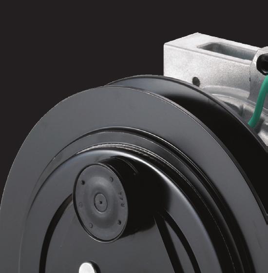
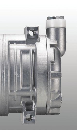
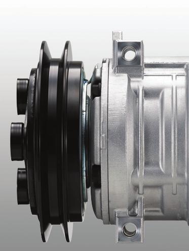
5 -4-1-Product description - Magnetic clutch Magnetic clutch* VALEO TM21 is available either as a compressor and magnetic clutch assembly or as a compressor body that customers can fit with compatible magnetic clutches. The magnetic clutch design Valeo has been promoting for more than 20 years is now gradually adopted by major market actors. Our compressors and magnetic clutches have successfully passed the thousand hours of long validation tests in the Valeo Compressors research center laboratory. Operational excellence was demonstrated during hot season testing on the field under challenging climates in the most stressful conditions. Our robust magnetic clutch provides the best way to reduce fuel consumption without using additional unloading devices that decrease significantly the efficiency and durability of the compressor. The range of Valeo magnetic clutches ensures an unmatched reliability and the longest durability that perfectly matches the Valeo TM21 compressor qualities. Specifications TM21 TYPE RATED VOLTAGE POWER CONSUMPTION STATIC TORQUE DIRECTION OF ROTATION WEIGHT V-BELT TYPE Electromagnetic single-plate dry clutch 12 VDC or 24 VDC 50 W maximum 40 N.m (min.) after burnishing : 59 N.m (min) Clockwise or counter clockwise (depending on clutch type) Approx 3.0 kg {6 lbs} V-groove (A or B) or V-ribbed (PK) *Please note that the maintenance procedures introduced in this service manual apply only to magnetic clutches provided by Valeo.

6
7 -6-1-Product description - Dimensions TM21 36 ±1 30 ' CLUTCH GAP 0.3~ ± Ø 145 Ø Ø124 Ø Ø8.8 ± ± ± : 5±1 N m 47.6 ± ± ( 64 ) R ± ±0.2 : 15-2 N m : N m
8 -7-1-Product description - Exploded view Center bolt 2. Armature assembly 3. Adjusting shim 4. Snap ring 5. Pulley assembly 6. Screw 7. Field coil 8. Bolt 9. Gasket 10. Shaft Seal assembly 11. Front cilynder head 12. O-Ring 13. Gasket 14. Valve plate assembly 15.Suction valve 16. Pin 17. Cylinder shaft assembly 18. Valve plate assenbly 19. Gasket 20. Rear cylinder head 21. O-ring 22. Plug 23. O-ring 24. Relief Valve 25. O-ring 26. Shipping plate 27. Bolt
9 -8-1-Product description - Performance The performance data below were measured under the following conditions: Compressor speed: 1450 rpm Suction Gas Temperature: 20 C Condensing Temperature ( C) Conditions Cooling capacity Q (kw) & Power consumption P (kw) Pd (MPaG) Evaporating Temperature ( C) Ps (MPaG) Q (kw) P (kw) Q (kw) P (kw) Q (kw) P (kw) Valeo TM21 conversion factors The performance data at different rotation speed can be approximated with the conversion factors below P Conversion factors Q Compressor speed (rpm)
10 -9-1-Product description - Swash plate system Valeo TM21 are 10-cylinder swash plate type compressors. With this type of compressor, the cylinders and pistons are arranged axially along the drive shaft. The pistons operate within the cylinders and are driven by a swash plate to perform suction, compression and discharge. Swash plate system The drive shaft, which is driven by the engine through the magnetic clutch, is equipped with a swash plate. The drive shaft is supported by two radial bearings and two thrust bearings. The swash plate is rotated by the drive shaft, and moves the pistons back and forth. Suction Radial bearing Thrust bearing Suction Piston Drive System The pistons in the cylinders are mounted on the swash plate through hemispherical shoes. Each piston has a compression head at each end. The rotation of the swash plate results in a reciprocating piston movement parallel to the drive shaft. The cylinders, which are arranged at 72 intervals around the drive shaft, are each divided into 2 chambers, providing 5 front and 5 rear bores. As each piston performs suction and compression at either end, the compressor operates as a 10-cylinder compressor. Compression Compression Ball Piston
11
12
13 -12-2-Operation precautions 1. During the off season of the air conditioner, operate the compressor for a few minutes once a week. 2. Do not drive through water. Water may damage the magnetic clutch, thus preventing normal operation. 3. Always charge the A/C system with the specified quantity of refrigerant. 4. Keep the compressor clear of water projection while cleaning the vehicle.
14 -13-3-Handling instructions Maintenance precautions Work area As the components of air conditioners are particularly sensitive to moisture, dirt and rust, always observe the following: Work indoors whenever possible Select a flat ground work area Keep the work area clean Select a work area with adequate ventilation. CAUTION! Refrigerant itself is not harmful, but excessive accumulation in a closed area can cause oxygen deficiency. Gasoline inflammables Safety glasses Gloves Keep open flame and inflammables away from the vehicle in which the air conditioner is being installed. (Fire is particularly dangerous during the gas leak inspection following installation) WARNING! Contact with flame and high temperatures can generate toxic gases. Refrigerant handling WARNING! Direct contact with refrigerant can cause frostbite or blindness. Always wear safety glasses and protective gloves. Do not work with refrigerant close to your face. 1. Do not misidentify refrigerants If an HFC-134a air conditioning system is mistakenly charged with another refrigerant, serious problems such as compressor seizing may occur. Therefore, confirm before charging with refrigerant that the type of air conditioning system is an HFC-134a system.
15 -14-3-Handling instructions Do not release refrigerant into the air FILL AUTO 2. Do not release refrigerant into the air Although HFC-134a is not subject to CFC regulations, it can have an effect on global warming and so should not be released into the air. When removing refrigerant from the air conditioner system, always use a refrigerant recovery unit made specifically for HFC-134a. Recovery unit Compressor handling Do not strike or unecessarily turn the compressor upside down. If the compressor is knocked over or turned upside down during handling or installation, rotate the armature plate 5 or 6 times by hand to circulate the oil. Otherwise, oil in the cylinder during compressor start-up will cause valve damage and reduce durability. Oil return operation Refrigrant recovery Compressor removal Oil inspection Compressor removal When the compressor is operational 1. Perform the oil return operation (see p.15). 2. Recover the refrigerant from the system using a refrigerant recovery unit. 3. Remove the compressor. 4. Drain the oil from the compressor and close all open connections immediately. 5. Check the oil quantity and the degree of contamination (see p.16). When the compressor is inoperable 1. Recover the refrigerant from the system using a refrigerant recovery unit if the shut-off valves are to be removed with the compressor. 2. Remove the compressor. 3. Drain the oil from the compressor and close all open connections immediately. 4. Check the oil quantity and the degree of contamination (see p.16).
16 -15-3-Handling instructions ON/OFF DUAL 20.0 AUTO ECON Oil return operation Compressor oil mixed with refrigerant is circulating in the air conditioning system. Perform the oil return operation to return this oil to the compressor before removing components from the system. 1. Open the doors and windows and operate the blower motor at maximum speed. 2. Operate the vehicle engine at idling during at least 20 minutes. Note: The maximum amount of oil cannot be recovered at higher speeds. This operation also requires a warm ambient temperature. Oil handling Oil specification Use only ZXL 100PG (DH-PS) Oil quantity inspection There is no particular need for frequent inspection or replacement, although it is recommended to check operating refrigerent pressures and oil levels at the start of the season. Please replace the refrigerant and restore the system oil and refrigerant charge to factory specifications if: the AC system is opened for repair or replacement of any component (e.g.: evaporator, condenser or receiver drier) any loss of charge - refrigerant or oil - is detected. Do not mix with other oils Handling precautions 1. The oil must be free from dust, metal filings, etc. 2. Do not mix oils. 3. The moisture content must not exceed 1,000 ppm. (PAG oil only) 4. The oil easily absorbs moisture when the container is open. Therefore always seal the container immediately after use. Cap the container immediately

17
18 -17-3-Handling instructions unit: cm 3 & cc Factory oil charge TM Amount recovered 108 or more Under 108 Current Compressor is kept Charging amount Same as recovered Compressor is replaced Amount to remove from new compressor 180-(amount recovered) CAUTION! The specified oil quantity differs, depending on the type of air conditioner system. A label describing the specified quantity is attached to the compressor. Additionally, all of the oil cannot be removed when draining the compressor as some will remain as an oil film on the inside of the compressor and the system components. Therefore, refer to the table on the left when recharging the compressor with oil. Excess oil adversely affects the cooling capacity and the compressor. unit: cu in Current Compressor is kept Compressor is replaced CAUTION! The oil filler plug O-ring must be replaced with a new one. Factory oil charge Amount recovered Charging amount Amount to remove from new compressor TM or more Same as recovered 10.9-(amount recovered) Under cm 3 (3 cu in) 10cm 3 (0.6 cu in) Replacement of components When replacing the system s component parts, supply the following amount of oil to the compressor. Component mounted Amount of oil Evaporator 50 cm 3 (3 cu in) Condenser 30 cm 3 (6 cu in) Receiver drier 30 cm 3 (1.8 cu in) After installing these component parts, check the compressor oil. Refer to page cm 3 (1.8cu in)
19 -18-3-Handling instructions Flexible hose Running-in operation Whenever moving parts have been replaced, it is necessary to run-in both the compressor and the magnetic clutch. Compressor running-in Reassembled compressors must be run-in after the leak test (see next page). 1. Check that the compressor contains the specified amount of oil. 2. Interconnect the suction fitting and the discharge fitting with the flexible hose. 3. Install the high pressure connector and the low pressure connector to the ports and tighten the bolts to the specified torque. 4. Connect the two connector ports using a flexible hose. 5. Run the compressor at 500 rpm for 30 minutes to 60 minutes. This operation may be performed by an electric motor or the engine of an automobile. 6. Replace the oil. 7. Repeat the leak test. CAUTION! While the compressor is being run-in in step 3 above, check the outside temperature of the front head. If the temperature exceeds 80 C (176 F), stop the running-in operation. Resume the operation when the head has cooled. High pressure connector OFF ON (50 times) Low pressure connector Magnetic clutch running-in 1. Install the clutch on the compressor. 2. Install the compressor on the test bench, and operate the compressor by running the system. 3. Maintain the compressor speed at 700 rpm. Operate the A/C switch through the ON/OFF cycle at least 50 times ( ON for 10 seconds and OFF for 10 seconds).
20 -19-3-Handling instructions Leak test The compressor must be checked for refrigerant leaks after it is repaired. The procedure is as follows. 1. Install the discharge and suctions caps on the compressors 2. Fill the compressor with refrigerant gaz through the suction port raising the pressure at least to 0.4 MPaG (55.3 psig) 3. Check the compressor for leaks using a leak detector ( ). Gas leak detector Parts No. FRAGILE UP FRAGILE Air Conditioning Compressor UP VALEO Japan Co Ltd, MADE IN JAPAN Storing a repaired compressor If it is necessary to store a repaired compressor for some time before installation, evacuate the compressor and fill it with dry nitrogen gas through the suction fitting to raise the pressure to 49 ~ 150 kpa {0.5 ~ 1.5 kgf/cm 2, 7.1 ~ 21 psi}.
21 -20-3-Handling Instructions Refrigerant charging In order to prevent a liquid charge and greatly increase risks of compressor dammage, do not shake or turn the refrigerant bottle upside-down. Initial Leak Check Using the leak detector, check the system connections for leaks. As the system pressure is not yet high, only large leaks can be detected at this time.
22 3-Handling Instructions Installation position The compressor should be installed in the vehicle within the range shown on the left-hand figure. If it is installed outside this range, the compressor will be adversely affected. This compressor is equipped with a pressure feed lubrication system, which cannot function if the compressor is installed outside this range. If the compressor is installed outside the range shown on the left-hand figure any or all warranties may be rendred void. Installation precautions The new compressor is filled with the specified quantity of compressor oil and nitrogen gas (N 2 ). When mounting the compressor on the vehicle, please follow as below: 1. Loosen the discharge side connector s cap and gently release nitrogen gas (N 2 ) from the compressor. 2. Turn the magnetic clutch s armature plate several times by hand to distribute the oil which has settled in the cylinders. 3. When installing the compressor in service system, the compressor should be installed after adjusting the amount of oil, referring to oil check p.16. CAUTION! Do not let the oil escape -21-
23 -22-3-Handling Instructions O-ring positions CORRECT INCORRECT INCORRECT O-ring Pipe bulge Apply oil thoroughly to these areas Piping connection Compressor / condenser connection Piping precautions 1. Position the O-Ring against the bulge in the pipe when connecting hoses and pipes. 2. Coat the piping connections and the O-rings with PAG oil. CAUTION! Always use the specified oil for HFC134a systems to coat the O-rings. Pipping connection procedure Union Nut CORRECT INCORRECT 3. Fit the nuts and unions tightly against the base of the companion pieces, then hand tighten the nut as much as possible. Then tighten to the specified torque. Damage Gnawing at pipe end ADVICE Valeo Compressors recommends the following hose sizes: INTERNAL DIAMETER Suction: Ø 12.5 mm - 1/2 inch Discharge: Ø 8 mm - 5/16 inch
24 -23-4-Troubleshooting Compressor troubleshooting When a problem occurs during the compressor operation, it is often difficult to pinpoint exact the cause of the malfunction. As long as the compressor maintenance is done correctly, there should not be any problem throughout the whole vehicle life, but should it happen, we hope this troubleshooting can help you solve the issue efficiently. Below are listed most of the issues you may encounter while the A/C is ON. Please refer to the compressor troubleshooting tree to localize the malfunction symptom, then look at the table (p.24-25) for the appropriate counter measure. Most of the malfunction symptoms can be classified in the following categories: 1. Insufficient cooling capacity 2. Abnormal noise 3. Smoke In case of insufficient cooling capacity, we recommend that you prepare a gauge manifold to measure the pressure of both discharge and suction sides (for a detailed diagnosis by gauge pressure, see p.26-27). Compressor troubleshooting tree 1. Insufficient cooling capacity A. Compressor is not running B. Compressor is running C. Compressor runs intermittently 2. Abnormal noise A. Abnormal noise from compressor B. Abnormal noise from magnetic clutch C. Belt slipping noise 3. Smoke A. Magnetic clutch friction surface slipping B. Magnetic clutch belt slipping C. Smoke from magnetic clutch D. Smoke from compressor
25 -24-4-Troubleshooting 1. Insufficient cooling capacity Issue Symptom Possible cause Measure Compressor is not running (No cool blow coming out) Magnetic clutch slips when turning on the A/C switch Low pressure cut switch operates (see p.26-27) Compressor internal part damage Refrigerant shortage Replace the compressor Fix the refrigerant leakage then fill with refrigerant until reaching the right amount The magnetic clutch slips or does not engage when the compressor runs Lead wire short circuit or wiring connector not seated properly Replace the lead wire if it is defective Magnetic clutch damage Repair or replace the magnetic clutch A Magnetic clutch air gap too wide Low magnetic clutch voltage Adjust air gap or replace magnetic clutch Check the voltage of battery Thermal fuse (if provided) opened by high heat Service system and replace the compressor The magnetic clutch engages but the armature does not rotate Belt slipping Replace the compressor if it is locked Belt run off the pulley Compressor internal part damage or magnetic clutch damage Replace the compressor or the magnetic clutch Center bolt is loose / Center bolt is missing Bolt drop off/ Armature drop off Replace magnetic clutch Compressor is running (No cool blow coming out) Compressor is running normally No difference of temperature between discharge side and suction side (see p.26-27) Poor compression Refrigerant shortage Replace the compressor Fix the refrigerant leakage then fill with refrigerant until reaching the right amount B The magnetic clutch slips or does not engage when the compressor is running Magnetic clutch friction surface slipping Check the voltage of battery or replace the magnetic clutch Loose connection of the magnetic clutch electrical circuit Replace the magnetic clutch after making sure it is defective Belt slipping The magnetic clutch does not engage Magnetic clutch belt slipping Defective thermostatic switch Belt tension readjustment Replace the thermostatic switch after making sure it is defective
26 -25-4-Troubleshooting Issue Symptom Possible cause Measure C Compressor runs intermittently (Cool blow comes out only from time to time) Both discharge and suction pressures are high The magnetic clutch slips or does not engage when the compressor is running Excess of refrigerant Condenser fan failure Loose connection of the magnetic clutch electrical circuit Reduce the refrigerant charge until reaching the right amount Replace the condenser after making sure it is defective Replace the magnetic clutch after making sure it is defective The magnetic clutch does not engage Defective thermostatic switch Replace the thermostatic switch after making sure it is defective
27 -26-4-Troubleshooting 2. Abnormal noise A Issue Symptom Possible cause Measure Abnormal noise from the compressor Abnormal vibration after turning on the A/C switch Abnormal noise from the compressor body Compressor installation bolt is loose Wide gap at the attaching portion between the compressor and the bracket Compressor body internal component damage Increase tightening torque of the loose bolts Improve the compressor attaching portion Replace the compressor B Abnormal noise from the magnetic clutch The magnetic clutch has a backlash and slips Strange noise when the magnetic clutch engages Magnetic clutch damage Air gap too wide Replace the magnetic clutch Adjust air gap or replace magnetic clutch Armature slips / does not engage when the compressor is running Magnetic clutch friction, slippery surface Check the voltage of battery or replace magnetic clutch C Belt slipping noise Armature does not rotate when magnetic clutch engages Belt slipping Replace the compressor if locked. Readjust the belt tension if the belt is loose 3. Smoke Issue Symptom Possible cause Measure A Magnetic clutch friction surface slipping The magnetic clutch slips / does not engage when the compressor is running Magnetic clutch air gap too wide Low magnetic clutch voltage Adjust air gap or replace magnetic clutch Check the voltage of battery Magnetic clutch friction, greasy surface Clean friction surface or replace magnetic clutch Magnetic clutch belt slipping The magnetic clutch slips / does not engage when the compressor is running Belt alignment is not correct Adjust the compressor installation position B Magnetic clutch belt is greasy Clean or replace the belt Magnetic clutch belt tension is loose Adjust belt tension C Smoke from the magnetic clutch The magnetic clutch does not engage Coil open or shorted Replace the magnetic clutch D Smoke from the compressor Refrigerant / oil is blowing out Refrigerant leaking, uncoupled piping or piping burst Refrigerant blowing from the high pressure relief valve due to excess of refrigerant Fix the refrigerant leakage then fill with refrigerant until having the right amount Reduce the refrigerant charge until reaching the right amount
28 4-Troubleshooting A/C cycle diagnosis by gauge pressure Following is a diagnosis procedure to connect gauge manifold to A/C cycle, measure suction and discharge pressures and analyze the defects of the cycle. Operation conditions of the A/C cycle for pressure measuring: 1. Ambient temperature: C 2. Engine speed: 1,500 rpm 3. A/C switch: ON 4. Blower speed: high 5. Temperature control: full cold Gauge pressure indication Pressure is normal Cause Confirmation method Action to take A/C cycle operates normally. If there is any defect (poor cooling performance), there shall be another cause Discharge pressure: around MPaG (10-17 kgf/cm²) Suction pressure: around MPaG ( kgf/cm²) Both discharge and suction pressures are low Suction pressure becomes vacuum Refrigerant shortage Receiver dryer is clogged Connect gauge manifold to cycle Temperature difference between inlet and outlet pipes happens. Dryer is covered with frost Recover refrigerant, then refill with the right amount of refrigerant Replace parts Expansion valve is clogged Expansion valve was covered with frost Clean or replace part Enclosure leakage from the Expansion valve s temperature sensing tube. (Expansion valve operates to close the valve opening) Outlet side of the Expansion valve is not cooling. (Low side of gauge indicates vacuum) Replace part Temperature sensing device at outlet air is defective Evaporator becomes frozen up Adjust or replace the part Refrigerant piping is clogged or crashed If any part between the dryer and the compressor is clogged or crashed, the low side pressure becomes vacuum Adjust or replace the part -27-
29 4-Troubleshooting Gauge pressure indication Both discharge and suction pressures are high Discharge pressure is high and suction pressure is low Discharge pressure is low and suction pressure is high Cause Confirmation method Action to take Excess of refrigerant Condenser cooling malfunction Misaligned Expansion valve or thermal sensing tube of the Expansion valve is not fit on regularly. (Excess opening of the Expansion valve) Air mixed in refrigeration cycle Refrigerant cycle is clogged between compressor and condenser Defect of the compressor valve or gasket Connect gauge manifold to cycle Condenser becomes muddy and fins are clogged and collapsed. Defect of cooling fan rotation. Malfunction of fan motor for condenser. Defective refrigerant flow control, the thermal sensing tube is not closely in contact with the evaporator pipe Just after compressor stops, discharge pressure will come down immediately to MPaG (3-4 kgf/cm²) Appreciable temperature difference at the clogged location Discharge and suction pressures balance immediately after the compressor stops. (Defective compression of compressor) Recover refrigerant, then refill with the right amount of refrigerant Clean up, hand repair of fin and replacement Adjustment or replacement Evacuate air from cycle, the charge with the adequate amount of refrigerant Clean up inside the cycle or replace the part Replace the compressor -28-
30 5-Tightening torques Part Thread size Tightening torque 1. Armature Bolt M6 x N m ( lbf ft) 2. Field coil screw M5 x N m ( lbf ft) 3. Body bolt M8 x N m ( lbf ft) 4. Oil drain plug M8 x N m ( lbf ft) 5. Pressure Relief valve 3/8-24UNF 8-10 N m ( lbf ft) 6. Connector fixing bolt M10 x N m ( lbf ft) 7. Fittings and ports 3/4-16UNF 7/8-14UNF 1-14UNS Maximum torque: 27 ( 2.8, 20 ) Maximum torque: 37 ( 3.8, 27 ) Maximum torque: 47 ( 4.8, 35 ) -29-
31 -30-6-Service procedures - Magnetic clutch Drive plate holder Magnetic clutch Removal 1. Remove the center bolt using the drive plate holder ( ) to prevent armature assembly rotation. 2. Remove the drive plate using the drive plate puller. Remove the shims from the compressor drive plate or drive shaft. 3. Remove the snapring using external snapring pliers. Snap ring External snap ring pliers Center pulley puller Pulley puller 4. Position the center pulley puller at the end of the driveshaft. 5. Attach a suitable pulley puller to the pulley. Hook the puller claws to the edge of the pulley as shown. 6. Tighten the center pulley puller bolt to remove the pulley. CAUTION! Do not clip the puller claws into the pulley groove to prevent pulley groove damage.
32 -31-6-Service procedures - Magnetic clutch Remover Remove the field coil s lead wire bushing using the remover ( ). 6. Remove the three field coil/compressor screws. Then remove the field coil. CAUTION! Do not hold the field coil by the harness. Inspection Armature assembly Pulley assembly Field coil 1. If the contact surface has been damaged by excessive heat, the armature and pulley must be replaced. 2. Check the appearance of the pulley assembly. If the contact surface of the pulley is excessively grooved due to slippage, both the pulley and armature must be replaced, The contact surfaces of the pulley assembly must be cleaned with a suitable solvent before reinstallation. 3. Check the field coil for a loose connector or cracked insulation.
33 Service procedures - Magnetic clutch Magnetic clutch Installation Field coil 1. Install the field coil on the compressor (with the harness on top) and tighten the mounting screws to the specified torque. Specified torque: 4 ~ 6 N m {0.4 ~0.6 kgf m, 3.0 ~ 4.4 lbf ft} Pulley assembly Press Pulley Installer Carefully place the wire harness bushing. 3. Install the pulley assembly using the pulley installer ( ) and a hand press. CAUTION! Use only a press to install the pulley assembly. Do not use a hammer. A hammer will damage or deform the pulley. Snap ring 4. Install the snap ring (beveled edge up) using external snapring pliers. External snap ring pliers
34 6- Service procedures - Magnetic clutch Adjusting shims Drive plate 5. Install the armature assembly on the driveshaft together with the original shim(s). Press the armature assembly down by hand. 6. Install the center bolt and tighten the bolt to the specified torque using the drive plate holder ( ) to prevent armature assembly from the rotating. Specified torque: 12 ~ 14 N m {1.2 ~ 1.4 kgf m, 8.9 ~ 10.3 lbf ft} CAUTION! After tightening the center bolt, check that the pulley rotates smoothly. Gap adjustment 0.3~0.7 mm Thickness gauge 7. Check that the clutch clearance is as specified. If necessary adjust the clearance using shim(s). Adjusting shims are available in the following thickness: Shim Part No Thickness mm ( in) mm ( in) mm ( in) Specified clearance: 0.3 ~ 0.7 mm (0.01 ~ 0.03 in) 8. Run-in the clutch as described on page
35 Services procedures - Shaft seal assembly Shaft seal assembly Removal 1. Remove the magnetic clutch assembly as described on page Remove the drain plug and then drain the oil. 3. Remove the five bolts securing the heads. 4. Remove the snapring using internal snapring pliers. Snapring Internal snapring pliers Remover Insert the remover ( ) into the shaft seal and turn it untill it hits the shaft seal case. Then, pull the remover up to remove the shaft seal.
36 Services procedures - Shaft seal assembly Inspection The shaft seal must not be reused. Always use a new shaft seal when reassembling the compressor. Ensure that the seal seat is free from lint and dirt that could damage the shaft seal lip. Guide Installation Before installation refer to Inspection p Clean the sealed section of the front cylinder head. 2. Coat the new shaft seal and the front cylinder head with clean compressor oil. If the slip faces are dirty, clean them with thinners and, after drying the clean faces, apply clean compressor oil to them. Shaft seal 3. Fit the guide ( ) onto the end of the drive shaft. 4. Insert the shaft seal through the guide into the front cylinder head. Remover Install the shaft seal as far as possible into the front cylinder head using the installing end of the remover ( ). Remove the guide ( ) from the drive shaft. Guide
37 Services procedures - Shaft seal assembly Snapring Internal snapring pliers 6. Install the snap ring using internal snap ring pliers. Press the snap ring using the installing end of the remover ( ) until a click is heard. Shaft seal Guide Snapring Note 1. When installing the snap ring, the round edge of the snap ring must face downward, as shown on the left-hand figure. 2. Check the snap ring is properly installed, as shown on the left-hand figure. Install the oil drain plug with a new O-ring, thinly coated with clean compressor oil, and tighten it to the specified torque. Specified torque: 13 ~ 15 N m {1.3 ~ 1.5 kgf m, 9.6 ~ 11 lbf ft}
38 Services procedures - Cylinder heads Bolts Cylinder heads (Front & Rear) Disassembly 1. Remove the magnetic clutch assembly as described on page Remove the drain plug and then drain the oil. 3. Remove the five bolts securing the heads. 4. Alternately tap the two projections on the front head using the remover ( ) and mallet to remove the front cylinder head. Tap lightly Remover Remove the O-ring from the front cylinder head, and then remove all the gasket material from the cylinder head. Gasket O-ring Front cylinder head 6. Remove the valve plate and suction valve from the cylinder shaft assembly and then remove all the gasket material from the valve plate. Suction valve Valve plate
39 Services procedures - Cylinder heads 7. To remove the rear cylinder head, alternately tap the two projections on the front head using the remover ( ) and mallet. 8. Remove the O-ring from the rear cylinder head, and then remove all the gasket material from the rear cylinder. Rear cylinder head O-ring Gasket 9. Remove the valve plate and suction valve from cylinder shaft assembly, then remove all the gasket material from the valve plate. Valve plate Suction valve Front cylinder head Valve plate Inspection Check the front and rear valve plates for scratched, bent or damaged parts. Inspect both cylinder heads and both valve plates for nicks or burrs on the sealing surfaces. Clean both cylinder heads and both valve plates or replace them if they are cracked or damaged. Check that none of the passengers in the valve plates are blocked.
40 Services procedures - Cylinder heads Piston Escape groove Suction valve Reassembly Rear cylinder head 1. Place the cylinder shaft assembly on the bench with the rear side up. 2. Install the rear suction valve so that it matches the roll pins. CAUTION! Ensure each valve matches each cylinder valve escape groove. 3. Install the rear valve plate on the rear suction valve. CAUTION! Do not mistake the front valve plate for the rear one. 4. Coat the new gasket with clean compressor oil and install it on the rear valve plate. Rear cylinder head Gasket 5. Coat the new O-ring with clean compressor oil and install it on the rear cylinder head. 6. Install the rear cylinder head. Suction valve Valve plate O-ring
41 Services procedures - Cylinder heads O-ring Valve plate Gasket Front cylinder head Suction valve Front cylinder head 1. Place the cylinder shaft assembly on the bench with the front side up. 2. Install the front suction valve so that it matches the pins. CAUTION! Ensure each valve matches each cylinder s valve escape groove. 3. Install the front valve plate on the front suction valve. 4. Coat the new gasket with clean compressor oil and install it on the front valve plate. 5. Position the guide on the shaft. 6. Coat the new O-ring with clean compressor oil and install it on the front cylinder head. 7. Install the front cylinder head. CAUTION! Align the roll pins and tap the head lightly and evenly with a plastic hammer. 8. Mount the new gaskets on the through-bolts. Insert the five through-bolts from the front cylinder head side and tighten them to the specified torque. Each bolt should be gradually tightened in three or more stages to ensure the specified torque. The bolts should be tightened in the order shown on the left-hand figure. Specified torque: 20 ~ 24 N m {2.0 ~ 2.4 kgf m, 14.8 ~ 17.7 lbf ft} 9. Install the oil drain plug with a new O-ring, thinly coated with clean compressor oil, and tighten it to the specified torque. Specified torque: 13 ~ 15 N m {1.3 ~ 1.5 kgf m, 9.6 ~ 11 lbf ft} 10. Fill the compressor with the specified amount of clean compressor oil through the suction-side connector. 11. Install the magnetic cluch (p. 32) 12. Run-in compressor (p. 18) 13. Carry out the leak test (p. 19)
42 -41-9-Service tools Compressor tools Part name Part No Reference page Application Remover For removing cylinder head and cylinder block Shaft Seal Remover For removing shaft seal Guide For installing shaft seal Drive plate holder To fix armature Test and inspection tools Part name Part No Reference page Application Gas leak detector For detecting gas leaks
43 10- Service parts 1.Compressor body service kits, sets and parts Item* Part name Reference Quantity OVERHAUL SET (O-RING SET + GASKET SET + SHAFT SEAL+ TRUST BEARING) O-RING SET O-ring body (front & rear head) n=2 O-Ring (center) n=1 O-Ring (plug) n=1 O-Ring (PRV) n=1 O-ring (Fitting) n=2 GASKET SET Gasket (front and rear head) n=2 Gasket (bolt) n=5 SHAFT SEAL SET Shaft seal assembly n=1 THRUST BEARING SET Thrust bearing n=2 OTHER COMPRESSOR PARTS - Valve plate assy (front) n=1 Valve plate assy (rear) n=1 Suction valve n=2 *See Product description - Exploded view (p.7) except for Trust bearing 2.Oil Item Part name Reference Quantity - ZXL 100PG (250 cc) cc -42-
44 Notes -43-
45 Notes -44-
46 Notes -45-
47 VALEO JAPAN - TM21 for HFC-134a SERVICE MANUAL Version: WW EN Published by: VALEO JAPAN CO, LTD. Copyright 2016, VALEO JAPAN CO, LTD. For any inquiry regarding the present service manual, contact us at vc-oura-sales@valeo.com -46-
48 Valeo TM21 Compressor Valeo TM21 Benefits High reliability Integration flexibility Great cooling capacity Enhanced performance Lower fuel consumption Compact & robust design Improved field serviceability Reduced noise and vibrations Staggering value through innovation Asia 39 Sendai, Kumagaya-shi Saitama-ken Japan Phone: +81 (0) Fax: +81 (0) China No.2677 Shiji Avenue, Eco. & Tec. Dvt Zone Changchun, Jilin PRC Phone: +86 (0) Fax: +86 (0) Europe, Middle East & Africa 8, rue Louis Lormand ZA de l Agiot Le Mesnil Saint Denis Cedex, La Verriere Phone: +33(0) vc-angers-sales@valeo.com Americas 2520 Esters Blvd #100 Dallas, TX United States Phone: Fax: vc-dallas-sales@valeo.com Copyright 2016 Valeo Japan CO., LTD. All Rights Reserved.
SERVICE MANUAL. Valeo TM21Compressor. Copyright 2015 Valeo Japan CO., LTD. All rights reserved.
 SERVICE MANUAL Valeo TM21Compressor Copyright 2015 Valeo Japan CO., LTD. All rights reserved. Foreword This service manual has been elaborated to help service personnel to provide efficient and correct
WARNINGS. Maintenance must be properly done to avoid serious injury risks. Improper maintenance can result in injury or property damage.
 Foreword This service manual has been elaborated to help service personnel to provide efficient and correct service and maintenance on the TM31 (formerly called DKS 32) compressor (for HFC-134a) for automotive
SERVICE MANUAL. Valeo TM08, TM13, TM15 & TM16 Compressors. Copyright 2013 Valeo Japan CO., LTD. All rights reserved.
 SERVICE MANUAL Valeo TM08, TM13, TM15 & TM16 Compressors Copyright 2013 Valeo Japan CO., LTD. All rights reserved. Foreword This service manual has been elaborated to help service personnel to provide
MANUAL CONTROL / SEMIAUTO TEMPERATURE CONTROL HEATING, VENTILATION AND AIR CONDITIONING SYSTEM
 SECTION 7C MANUAL CONTROL / SEMIAUTO TEMPERATURE CONTROL HEATING, VENTILATION AND AIR CONDITIONING SYSTEM CAUTION: Disconnect the negative battery cable before removing or installing any electrical unit
UX330 Compressor Service Manual
 UX330 Compressor Service Manual UX330 Compressor Service Manual Table of contents: 1. Specifications UX330. 1 Magnetic clutch 2 2. Component part list I. Compressor part numbers 3 II. Exploded view 4 3.
A Series UP90 UP120 UP150 UP170 Compressor Service Manual
 TM A Series UP90 UP120 UP150 UP170 Compressor Service Manual A Group Compressor Service Manual Table of contents: 1. Specifications UP90/UP120/UP150/UP170. 1 Magnetic clutch 2 Rear cap.2 2. Component
COMPRESSORS REPLACEMENT PROCEDURE
 COMPRESSORS REPLACEMENT PROCEDURE INTRODUCTION Shown below, you can find the procedure that you must follow to replace compressors. INSTALLATION INSTRUCTION Steps to follow: 1) Remove the damaged compressor
A/C COMPRESSOR SERVICING Article Text 1991 Saab 9000 For Copyright 1997 Mitchell International Friday, October 15, :22PM
 Article Text ARTICLE BEGINNING 1991 GENERAL SERVICING Compressor Service * PLEASE READ THIS FIRST * CAUTION: When discharging air conditioning system, use only approved refrigerant recovery/recycling equipment.
ENGINE COOLING SYSTEM
 B ENGINE A SECTION ENGINE COOLING SYSTEM CO C D CONTENTS E PRECAUTIONS... 2 Precautions for Liquid Gasket... 2 REMOVAL OF LIQUID GASKET SEALING... 2 LIQUID GASKET APPLICATION PROCEDURE... 2 PREPARATION...
AIR CONDITIONING SYSTEM
 AC-1 AIR CONDITIONING SYSTEM GENERAL INFORMATION DESCRIPTION TROUBLESHOOTING PREPARATION REFRIGERATION SYSTEM DRIVE BELT REFRIGERATION LINES COMPRESSOR RECEIVER CONDENSOR COOLING UNIT COOL/ICE BOX EVAPORATORS
ENGINE LUBRICATION & COOLING SYSTEMS SECTIONLC CONTENTS. ENGINE LUBRICATION SYSTEM...2 Precautions...2
 ENGINE LUBRICATION & COOLING SYSTEMS SECTIONLC CONTENTS ENGINE LUBRICATION SYSTEM...2 Precautions...2 LIQUID GASKET APPLICATION PROCEDURE...2 Preparation...2 SPECIAL SERVICE TOOLS...2 Lubrication Circuit...3
POWER STEERING TO INDEX POWER STEERING SYSTEM PRECAUTIONS... OPERATION CHECK... PROBLEM SYMPTOMS TABLE... VANE PUMP ASSEMBLY COMPONENTS...
 TO INDEX STEERING POWER STEERING POWER STEERING SYSTEM PRECAUTIONS.............................................. OPERATION CHECK......................................... PROBLEM SYMPTOMS TABLE.................................
Section 10 Chapter 17
 Section 10 Chapter 17 24 Valve, 8.3 Liter Engine Air Intake System Note: All coding used in the 8.3 Liter and 9 Liter engine manuals are Cummins engine codes. These engine codes have no meaning to New
5/21/2018 G 3.3 DOHC > Heating,Ventilation, Air Conditioning > Air conditioning System > Compressor > Repair procedures 2009 Hyundai Sonat
 2009 Sonata Report a problem with this article Removal 1. If the compressor is marginally operable, run the engine at idle speed, and let the air conditioning work for a few minutes, then shut the engine
POWER STEERING SYSTEM
 SYSTEM 511 SYSTEM PRECAUTION 5105K01 1. HANDLING PRECAUTIONS ON STEERING SYSTEM (a) Care must be taken to when replacing parts. Incorrect replacement could affect the performance of the steering system
Radiator Service Tool Set Hexagon Wrench Set TOYOTA Electrical Tester Set. Capacity
 ENGINE EG329 PREPARATION SST (SPECIAL SERVICE TOOLS) 0923001010 Radiator Service Tool Set 0923114010 Punch 2JZGE only (Aluminum type) RECOMMENDED TOOLS 0904000010 Hexagon Wrench Set 0908200050 TOYOTA Electrical
HEATER, AIR CONDITIONER AND VENTILATION
 55-1 HEATER, AIR CONDITIONER AND VENTILATION CONTENTS HEATER AND MANUAL AIR CONDITIONER...................... 3 GENERAL............................... 3 Outline of Change......................... 3 SERVICE
TURBOCHARGER SYSTEM TURBOCHARGER TC 1
 TURBOCHARGER SYSTEM TURBOCHARGER TC1 TC2 TURBOCHARGER SYSTEM Description DESCRIPTION Systems which increase the amount of air sent to the engine are either turbocharger type (using exhaust gas to turn
BRAKE E
 8-1 GENERAL...8-2 SPECIFICATIONS...8-6 COMPONENTS...8-7 FRONT BRAKE...8-12 DISASSEMBLY INSPECTION REASSEMBLY (Pn1, Cu2 3 TON SERIES)...8-12 DISASSEMBLY INSPECTION REASSEMBLY (Pn2 3 TON SERIES)...8-17 BRAKE
Air Trap TATSU2. Copyright 2013 by TLV CO., LTD. All rights reserved ISO 9001/ ISO M-02 (TATSU2) 7 August 2013.
 7 August 2013.") 172-65177M-02 (TATSU2) 7 August 2013 ISO 9001/ ISO 14001 Manufacturer Kakogawa, Japan is approved by LRQA LTD. to ISO 9001/14001 Air Trap TATSU2 Copyright 2013 by TLV CO., LTD. All rights reserved 1 Contents
172-65177M-02 (TATSU2) 7 August 2013 ISO 9001/ ISO 14001 Manufacturer Kakogawa, Japan is approved by LRQA LTD. to ISO 9001/14001 Air Trap TATSU2 Copyright 2013 by TLV CO., LTD. All rights reserved 1 Contents
Compressor - Install (E.40.C.31 - F.10.A.15)
") Compressor - Install (E.40.C.31 - F.10.A.15) 1. Set the compressor on its mount and secure into place using the four bolts. Connect the refrigerant suction line (5) and the discharge line (4). Install
Compressor - Install (E.40.C.31 - F.10.A.15) 1. Set the compressor on its mount and secure into place using the four bolts. Connect the refrigerant suction line (5) and the discharge line (4). Install
HIGH FUEL PRESSURE LINE
 16 07 HIGH FUEL PRESSURE LINE High Pressure Pump Description This pump generates high fuel pressure and is driven by timing chain (radial plunger principle). This pump pressurizes the fuel to approx. 1600
2008 Toyota RAV ELECTRICAL Charging (2AZ-FE) - RAV4
 - RAV4") 2008 ELECTRICAL Charging (2AZ-FE) - RAV4 CHARGING SYSTEM PRECAUTION 1. Check that the battery cables are connected to the correct terminals. 2. Disconnect the battery cables if a quick charge is given
2008 ELECTRICAL Charging (2AZ-FE) - RAV4 CHARGING SYSTEM PRECAUTION 1. Check that the battery cables are connected to the correct terminals. 2. Disconnect the battery cables if a quick charge is given
SERIES PC INSTRUCTION AND OPERATION MANUAL
 MEGGA SERIES PC INSTRUCTION AND OPERATION MANUAL Models PCT and PCF Close-coupled and frame-mounted single-stage horizontal end-suction pumps. WARNING: Read this manual before installing or operating this
TURBOCHARGER Toyota Celica DESCRIPTION OPERATION TURBOCHARGING SYSTEMS All Models
 TURBOCHARGER 1988 Toyota Celica 1988 TURBOCHARGING SYSTEMS All Models DESCRIPTION Most models use a water-cooled turbocharger, mounted directly to the exhaust manifold with a wastegate assembly attached
INSTALLATION INSTRUCTIONS
 INSTALLATION INSTRUCTIONS Accessory Application Publications No. AIR CONDITIONER CIVIC 2- AND 4-DOOR AII 24158 Issue Date SEP 2002 What s New The installation instructions for the 2003 Civic A/C are the
AIR CONDITIONER SECTION AC CONTENTS AUTO
 AIR CONDITIONER SECTION AC CONTENTS AUTO PRECAUTIONS AND PREPARATION SRS Airbag Pretensioner Seatbelt... 4 A/C Refrigerant HFC134a Handling... 4 Compressor Oil... 4 Tube Connection... 4 O-Ring Part Number...
2.- HANDLING OF VALVES BEFORE ASSEMBLY 3.- FITTING THE VALVE TO THE REST OF THE ASSEMBLY 5.- PERIODICAL INSPECTION OF THE VALVE AND MAINTENANCE
 Page 1 of 16 CONTENTS 1.- INTRODUCTION 2.- HANDLING OF VALVES BEFORE ASSEMBLY 3.- FITTING THE VALVE TO THE REST OF THE ASSEMBLY 4.- OPERATION OF A BALL VALVE 5.- PERIODICAL INSPECTION OF THE VALVE AND
INSTRUCTION MANUAL INTERNAL GEAR PUMP TITAN G-4124A SERIES=> FLANGED TITAN G-124A SERIES => FLANGED MODELS:
 INSTRUCTION MANUAL INTERNAL GEAR PUMP TITAN G-4124A SERIES=> FLANGED TITAN G-124A SERIES => FLANGED MODELS: G-H, G-HL, G-K, G-KK, G-L, G-LQ, G-LL, GLS, G-Q, G-QS 1 Contents Maintenance Thrust bearing adjustment
A/C SYSTEM GENERAL DIAGNOSTIC PROCEDURES
 Article Text ARTICLE BEGINNING 1993 AIR CONDITIONING & HEAT A/C General Diagnostic Procedures Diagnosis is an important first step in A/C system servicing. To save time and effort, systems should be carefully
Jeep Wrangler TJ 4.0 LITER Installation instructions
 www.jeepair.com 2000-2001 Jeep Wrangler TJ 4.0 LITER Installation instructions Important information about your system, and warranty DO NOT ADD ANY OIL TO ANY PART OF THE SYSTEM. DO NOT USE THE SIGHT GLASS
PACKING, HANDLING, TRANSPORTING AND STORING MOTORS
 PACKING, HANDLING, TRANSPORTING AND STORING MOTORS Make sure that the shaft of the motor is not loaded in any way and is protected from knocks. Axial loads or shocks may easily damage the bearings inside
Service Manual. Climate Control Inc.
 SECTION 2 Service - Clutch Servicing (Removal & Installation) - Shaft Seal Servicing (Removal & Installation) - Head & Valve Plate Servicing (Removal & Installation) - Baseplate Servicing (Removal & Installation)
Call the A/C Experts SD Compressor Service Guide
 Call the A/C Experts SD Compressor Service Guide Table of Contents 1. Compressor Models Covered 2. Compressor Nomenclature 3. Cautionary Information 3.1 Pressure Release 3.2 Recovery of Refrigerant 3.3
COOLING SYSTEM. Return to Main Table of Contents
 COOLING SYSTEM Return to Main Table of Contents GENERAL... 2 COOLING SYSTEM... 7 RADIATOR... 9 ENGINE COOLANT PUMP... 12 THERMOSTAT... 14 ENGINE COOLANT TEMPERATURE SENDER &, SENSOR... 15 ENGINE COOLANT
SUPERCHARGER. ON-VEHICLE INSPECTION 1. INSPECT SUPERCHARGER OIL LEVEL HINT: With the engine cold, check the oil level on the dipstick.
 EG45 ONVEHICLE INSPECTION 1. INSPECT OIL LEVEL HINT: With the engine cold, check the oil level on the dipstick. (a) Park the vehicle on a level spot and turn the engine off. (b) 4WD: Remove the LH front
Technical Service BULLETIN
 Technical Service BULLETIN Title: Models: 01 03 Sequoia TSB UPDATE NOTICE: The information contained in this TSB supercedes TSBs AC001 01 and AC001 02. The previous TSBs, AC001 01 and AC001 02, should
ENGINE COOLING SYSTEM
 B ENGINE A SECTION ENGINE COOLING SYSTEM CO C D CONTENTS E PRECAUTIONS... 2 Precautions for Supplemental Restraint System (SRS) AIR BAG and SEAT BELT PRE-TEN- SIONER... 2 Precautions for Liquid Gasket...
GROUP CONTENTS GENERAL DESCRIPTION RADIATOR SPECIAL TOOL THERMOSTAT ENGINE COOLING DIAGNOSIS...
 14-1 GROUP 14 CONTENTS GENERAL DESCRIPTION 14-2 SPECIAL TOOL 14-2 ENGINE COOLING DIAGNOSIS 14-3 INTRODUCTION 14-3 TROUBLESHOOTING STRATEGY 14-3 SYMPTOM CHART 14-3 SYMPTOM PROCEDURES 14-4 ON-VEHICLE SERVICE
Table of Contents. 4. Before a New Turbocharger is Installed
 Table of Contents 1. Turbocharger Overview ------------------------------------------------------------------ 1.1. Definition -----------------------------------------------------------------------------
ENGINE TUNE-UP INSPECTION OF ENGINE COOLANT INSPECTION OF ENGINE OIL INSPECTION OF BATTERY. INSPECTION OF AIR FILTER (Paper Filter Type)
") ENGINE MECHANICAL - Engine Tune-Up EM-17 ENGINE TUNE-UP INSPECTION OF ENGINE COOLANT (See steps 1 and 2 on page CO-4) INSPECTION OF ENGINE OIL (See steps 1 and 2 on page LU-5) INSPECTION OF BATTERY (See
ENGINE MECHANICAL - Engine Tune-Up EM-17 ENGINE TUNE-UP INSPECTION OF ENGINE COOLANT (See steps 1 and 2 on page CO-4) INSPECTION OF ENGINE OIL (See steps 1 and 2 on page LU-5) INSPECTION OF BATTERY (See
ENGINE COOLING SYSTEM
 B ENGINE A SECTION ENGINE COOLING SYSTEM CO C D CONTENTS E PRECAUTIONS... 2 Precautions for Supplemental Restraint System (SRS) AIR BAG and SEAT BELT PRE-TEN- SIONER... 2 Precautions for Liquid Gasket...
OVERHAUL 1. REMOVE OIL FILLER CAP SUB ASSY. 2. REMOVE CYLINDER HEAD COVER SUB ASSY (a) Remove the 10 bolts, 2 nuts, cylinder head cover and gasket.
 Remove the 10 bolts, 2 nuts, cylinder head cover and gasket.") 144 ENGINE MECHANICAL OVERHAUL 1. REMOVE OIL FILLER CAP SUBASSY 1410H01 2. REMOVE CYLINDER HEAD COVER SUBASSY (a) Remove the 10 bolts, 2 nuts, cylinder head cover and gasket. A11090 3. REMOVE CAMSHAFT
144 ENGINE MECHANICAL OVERHAUL 1. REMOVE OIL FILLER CAP SUBASSY 1410H01 2. REMOVE CYLINDER HEAD COVER SUBASSY (a) Remove the 10 bolts, 2 nuts, cylinder head cover and gasket. A11090 3. REMOVE CAMSHAFT
ENGINE COOLING GROUP CONTENTS RADIATOR GENERAL DESCRIPTION SPECIAL TOOLS THERMOSTAT
 14-1 GROUP 14 CONTENTS GENERAL DESCRIPTION 14-2 SPECIAL TOOLS 14-3 DIAGNOSIS 14-3 INTRODUCTION 14-3 TROUBLESHOOTING STRATEGY 14-3 SYMPTOM CHART 14-4 SYMPTOM PROCEDURES 14-4 ON-VEHICLE SERVICE 14-17 ENGINE
COOLING SYSTEM ON-VEHICLE INSPECTION CO 1
 Radiator Cap Tester 2AZ-FE OLING OLING SYSTEM A112194E01 A112306 OLING SYSTEM ON-VEHICLE INSPECTION 1 1. CHECK OLING SYSTEM FOR LEAKS (a) Remove the radiator reservoir cap. CAUTION: To avoid the danger
ENGINE 6G74 3.5L-SOHC-24 VALVE
 11A ENGINE General Information/Service Specifications ENGINE 6G74 3.5L-SOHC-24 VALVE GENERAL INFORMATION Items Specifications Type V-type, Over Head Camshaft Number of cylinders 6 Bore mm 93.0 Stroke mm
Single Stage Rotary Vane Vacuum Pump Installation and Operation Manual RX-40 RX-63 RX-100
 V acuum Pumps Single Stage Rotary Vane Vacuum Pump Installation and Operation Manual RX-40 RX-63 RX-100 www.republicsales.com Revised 02.15 2015 Republic Sales & Manufacturing Single Stage Rotary Vane
1/2" AIR DRIVEN DIAPHRAGM PUMP
 1/2" DRIVEN DIAPHRAGM PUMP OPERATION AND SERVICE GUIDE O-1225D NOV. 2008 Page 1 of 6 Refer to Bulletin P-605, Parts List P-9151 DRIVEN, DOUBLE DIAPHRAGM PUMP MANUAL Congratulations on purchasing one of
WEBER CARBURETOR TROUBLESHOOTING GUIDE
 This guide is to help pinpoint problems by diagnosing engine symptoms associated with specific vehicle operating conditions. The chart will guide you step by step to help correct these problems. For successful
5-2 FUEL SYSTEM AND THROTTLE BODY FUEL SYSTEM FUEL DELIVERY SYSTEM The fuel delivery system consists of the fuel tank, fuel pump, fuel filters, fuel f
 FUEL SYSTEM AND THROTTLE BODY 5-1 FUEL SYSTEM AND THROTTLE BODY I CONTENTS FUEL SYSTEM 5-2 FUEL DELIVERY SYSTEM 5-2 FUEL PUMP 5-3 FUEL PRESSURE REGULATOR 5-4 FUEL INJECTOR 5-4 FUEL PUMP CONTROL SYSTEM
MAINTENANCE MANUAL FOR THERMOSTATIC TEMPERATURE REGULATING VALVE TRAC STYLE P
 MANUAL NUMBER P-EFS-1 MAINTENANCE MANUAL FOR THERMOSTATIC TEMPERATURE REGULATING VALVE TRAC STYLE P TRAC Regulator Company Inc. 160 South Terrace Avenue Mount Vernon, New York USA 10550-2408 Phone: (914)
COMPRESSOR REMOVAL OF MANIFOLD GAUGE SET ON VEHICLE INSPECTION AC 18 AIR CONDITIONING SYSTEM
 AC18 AIR CONDITIONING SYSTEM 5. CONNECT STOP VALVES TO SERVICE VALVES Tighten the nuts by hand. CAUTION: Do not connect the wrong valves to the high pressure and the low pressure sides. To prevent loosening
13. CRANKCASE/CRANKSHAFT/BALANCER/PISTON/CYLINDER
 13. CRANKCASE/CRANKSHAFT/BALANCER/PISTON/CYLINDER COMPONENT LOCATION 13-2 SERVICE INFORMATION 13-3 TROUBLESHOOTING 13-4 CRANKCASE SEPARATION 13-5 CRANKSHAFT 13-7 MAIN JOURNAL BEARING 13-9 CRANKPIN BEARING
Section 10 Chapter 7
 Section 10 Chapter 7 24 Valve, 8.3 Liter Engine Troubleshooting Symptoms Identification Note: All coding used in the 8.3 Liter and 9 Liter engine manuals are Cummins engine codes. These engine codes have
ENGINE COOLING SYSTEM
 B ENGINE A SECTION ENGINE COOLING SYSTEM CO C D CONTENTS E PRECAUTIONS... 2 Precautions for Liquid Gasket... 2 REMOVAL OF LIQUID GASKET SEALING... 2 LIQUID GASKET APPLICATION PROCEDURE... 2 PREPARATION...
Cooling system components, removing and installing
 19-1 Cooling system components, removing and installing Note: When the engine is warm the cooling system is under pressure. If necessary release pressure before starting repair work. Hoses are secured
Float Dynamic Steam Trap J10
 172-65237MA-01 (J10) 12 June 2015 ISO 9001/ ISO 14001 Manufacturer Kakogawa, Japan is approved by LRQA LTD. to ISO 9001/14001 Float Dynamic Steam Trap J10 Copyright 2015 by TLV CO., LTD. All rights reserved
Free Float Air Trap G8
 172-65193MA-06 (G8) 24 June 2015 ISO 9001/ ISO 14001 Manufacturer Kakogawa, Japan is approved by LRQA LTD. to ISO 9001/14001 Free Float Air Trap G8 Copyright 2015 by TLV CO., LTD. All rights reserved 1
ENGINE COOLING Click on the applicable bookmark to selected the required model year
 ENGINE COOLING - ENGINE COOLING General Information/ Service Specifications/Lubricant/Sealants GENERAL INFORMATION 0000 The cooling system is designed to keep every part of the engine at appropriate temperature
HYDRAULICS. TX420 & & lower. Hydraulic Tandem Pump Removal. 4. Remove the LH side panel (Fig. 0388).
.") TX420 & 425 240000299 & lower 4. Remove the LH side panel (Fig. 0388). Hydraulic Tandem Pump Removal Note: Cleanliness is a key factor in a successful repair of any hydraulic system. Thoroughly clean all
TX420 & 425 240000299 & lower 4. Remove the LH side panel (Fig. 0388). Hydraulic Tandem Pump Removal Note: Cleanliness is a key factor in a successful repair of any hydraulic system. Thoroughly clean all
Installation Vertical Pump: Installation 'CM' and 'CDM' Style: Operation:
 Installation Vertical Pump: Gusher vertical end suction pumps with integral shaft is easily installed and put into service. With the one piece shaft design there is no couplings to align, no shims or no
Repair any problems or leaks before retrofitting. Affix labels to the vehicle showing conversion status. Observe all safety recommendations.
 The use of R134a in mobile A/C systems designed for R-1 2 refrigerant causes higher discharge pressures (as much as 10-15%) and necessitates changing the compressor lubricant from mineral oil (5GS) to
ENGINE COOLING SYSTEM
 ENGINE SECTION CO A ENGINE COOLING SYSTEM CO C D CONTENTS E PRECAUTION... 2 PRECAUTIONS... 2 Precaution for Supplemental Restraint System (SRS) "AIR BAG" and "SEAT BELT PRE-TEN- SIONER"...2 Precaution
GENERAL SPECIFICATIONS 25-2 GENERAL. Water cooling, forced circulation with electric fan
 COOLING SYSTEM GENERAL 2 COOLING SySTEM 8 RADIATOR 10 RADIATOR FAN MOTOR ASSY 12 WATER PUMP 14 THERMOSTAT 16 WATER HOSE AND PiPE 17 WATER TEMPERATURE GAUGE UNIT AND SENSOR 18 GENERAL GENERAL Y25CAOA SPECIFICATIONS
Failure Mode Analysis
 Presented by: Brunno Covolan Pg. 1 : Introduction What is Failure Mode Analysis? Looking at the compressor to determine what was the cause of the failure. Why do we need to conduct Failure Mode Analysis?
Car FEAD Air Conditioning Add-On Kit AB
 1 Car FEAD Air Conditioning Add-On Kit 77072446AB 5.7L & 6.4L Crate HEMI www.mopar.com Call Out Description Part Number Quantity Car AC Add-On Kit 77072446AB 1 COMPRESSOR, Air Conditioning, Fixed Disp.
A/C-HEATER SYSTEM - AUTOMATIC
 A/C-HEATER SYSTEM - AUTOMATIC 1988 Toyota Celica 1988 Automatic A/C-Heater Systems Celica * PLEASE READ THIS FIRST * CAUTION: When discharging air conditioning system, use only approved refrigerant recovery/recycling
DRIVE AXLE Volvo 960 DESCRIPTION & OPERATION AXLE IDENTIFICATION DRIVE AXLES Volvo Differentials & Axle Shafts
 DRIVE AXLE 1994 Volvo 960 1994 DRIVE AXLES Volvo Differentials & Axle Shafts 960 DESCRIPTION & OPERATION All 960 station wagon models use type 1041 rear axle assembly. All 960 4-door models use type 1045
2005 Toyota RAV AUTOMATIC TRANSMISSIONS U240E & U241E Overhaul
 2001-05 AUTOMATIC TRANSMISSIONS U240E & U241E Overhaul APPLICATION CAUTION: Flush oil cooler and oil cooler lines prior to transaxle installation. Oil cooling system contamination may cause premature transaxle
CHARGING SYSTEM PRECAUTION CH 1
 1NZ-FE ARGING ARGING SYSTEM ARGING SYSTEM PRECAUTION 1 1. Check that the battery cables are connected to the correct terminals. 2. Disconnect the battery cables when the battery is given a quick charge.
Manufacturer Kakogawa, Japan DC5S
 ISO 9001/ ISO 14001 Manufacturer Kakogawa, Japan is approved by LRQA LTD. to ISO 9001/14001 Cyclone Separator Trap DC5S Copyright 2015 by TLV Co., Ltd. All rights reserved 1 Contents Introduction... 1
Cooling system components, removing and installing
 Page 1 of 40 19-1 Cooling system components, removing and installing WARNING! The cooling system is pressurized when the engine is warm. When opening the expansion tank, wear gloves and other appropriate
GENESIS COUPE(BK) > 2010 > G 3.8 DOHC > Steering System
 > 2010 > G 3.8 DOHC > Steering System") GENESIS COUPE(BK) > 2010 > G 3.8 DOHC > Steering System Steering System > General Information > Specifications Specifications Steering gear Oil pump Steering angle Power steering oil Item Specification
GENESIS COUPE(BK) > 2010 > G 3.8 DOHC > Steering System Steering System > General Information > Specifications Specifications Steering gear Oil pump Steering angle Power steering oil Item Specification
Single Stage Rotary Vane Vacuum Pump Installation and Operation Manual RX-10 RX-21 RX-25
 V acuum Pumps Single Stage Rotary Vane Vacuum Pump Installation and Operation Manual RX-10 RX-21 RX-25 www.republicsales.com Revised 10.14 2014 Republic Sales & Manufacturing Single Stage Rotary Vane Vacuum
2004 IMPREZA SERVICE MANUAL QUICK REFERENCE INDEX
 2004 IMPREZA SERVICE MANUAL QUICK REFERENCE INDEX ENGINE SECTION 1 FU(H4SO) EMISSION CONTROL (AUX. EMISSION CONTROL DEVICES) INTAKE (INDUCTION) EC(H4SO) IN(H4SO) This service manual has been prepared to
GROUP 13C 13C-1 CONTENTS GENERAL DESCRIPTION... 13C-2 FUEL TANK... 13C-11 FUEL SUPPLY DIAGNOSIS... 13C-3 SPECIAL TOOLS... 13C-8
 13C-1 GROUP 13C CONTENTS GENERAL DESCRIPTION......... 13C-2 DIAGNOSIS....... 13C-3 INTRODUCTION TO DIAGNOSIS........................ 13C-3 TROUBOLESHOOTING STRATEGY..... 13C-3 SYMPTOM CHART...................
26 - COOLING SYSTEM CONTENTS ENGINE COOLING - DESCRIPTION... 3 ENGINE COOLING - OPERATION... 9 COOLING SYSTEM FAULTS... 1
 26 - COOLING SYSTEM CONTENTS Page LAND ROVER V8 DESCRIPTION AND OPERATION ENGINE COOLING - DESCRIPTION... 3 ENGINE COOLING - OPERATION... 9 FAULT DIAGNOSIS COOLING SYSTEM FAULTS... 1 REPAIR COOLANT - DRAIN
Compressor Installation Guide. Technical helpline :
 Compressor Installation Guide Technical helpline : 0843 330 4097 Compressor Installation All air-conditioning repairs should only be undertaken by someone that has sufficient knowledge and training that
OIL AND FILTER INSPECTION
 F 20 C 29 Recommended Viscosity (SAE): 0 18 20 7 5W30 40 4 60 16 80 27 LUBRICATION (2UZFE) 100 38 TEMPERATURE RANGE ANTICIPATED BEFORE NEXT OIL CHANGE B16233 OIL AND FILTER OIL AND FILTER INSPECTION 1.
SERIES G3DB/AG3DB ELEVATOR
 TM INSTRUCTIONS AND PARTS LIST SERIES G3DB/AG3DB ELEVATOR WARNING This manual, and GENERAL INSTRUCTIONS MANUAL, CA-1, should be read thoroughly prior to pump installation, operation or maintenance. SRM00059
2012 Kia Soul L4 2.0L
 2012 Kia Soul L4 2.0L Vehicle» Engine, Cooling and Exhaust» Engine» Timing Chain» Service and Repair» Repair Procedures» Part 1 Removal Engine removal is not required for this procedure. CAUTION: Use fender
Maintenance Information
 16573370 Edition 2 February 2014 Air Grinder 99V Series Maintenance Information Save These Instructions Product Safety Information WARNING Failure to observe the following warnings, and to avoid these
LUBRICATION SYSTEM (April, 2003)
") SYSTEM (April, 2003) SYSTEM (April, 2003) ONVEHICLE INSPECTION 1. CHECK ENGINE OIL LEVEL (a) After warming up the engine and then 5 minutes after the engine stops, oil level should be between the L and
SYSTEM (April, 2003) SYSTEM (April, 2003) ONVEHICLE INSPECTION 1. CHECK ENGINE OIL LEVEL (a) After warming up the engine and then 5 minutes after the engine stops, oil level should be between the L and
13. FUEL SYSTEM/CARBURETOR/
 13 FUEL SYSTEM/CARBURETOR/FUEL PUMP FUEL SYSTEM --------------------------------------------------------- 13-1 SCHEMATIC DRAWING ---------------------------------------------- 13-2 OPERATION OF CARBURETOR
AIR COMPRESSOR OPERATING INSTRUCTION AND PARTS LIST
 AIR COMPRESSOR OPERATING INSTRUCTION AND PARTS LIST BELT TYPE IMPORTANT PLEASE MAKE CERTAIN THAT THE PERSON WHO IS TO USE THIS EQUIPMENT CAREFULLY READS AND UNDERSTANDS THESE INSTRUCTIONS BEFORE STARTING
TROUBLESHOOTING SPECIAL TOOL ASSEMBLY AND ADJUSTMENT
 1 INDEX Models FD, FE, FF and SG REAR AXLE 10-1 10-108E-07 CHAPTER 10 REAR AXLE Models FD, FE, FF and SG TROUBLESHOOTING...10-2 10 SPECIAL TOOL...10-3 WHEEL HUB AND RELATED PARTS DISASSEMBLY...10-7 INSPECTION...10-9
REAR FINAL DRIVE SECTION RFD CONTENTS D DRIVELINE/AXLE RFD-1 RFD
 REAR FINAL DRIVE D DRIVELINE/AXLE SECTION RFD A REAR FINAL DRIVE B C RFD CONTENTS E PRECAUTIONS... 2 Precautions... 2 PREPARATION... 3 Special Service Tools... 3 Commercial Service Tools... 5 NOISE, VIBRATION
2/17/2017 Timing Belt Service and Repair, Removal and Replacement
 http://repair.alldata.com/alldata/article/display.action?componentid=64&itypeid=401&nonstandardid=0&vehicleid=39554&miles=&printfriendly=com 1/22 http://repair.alldata.com/alldata/article/display.action?componentid=64&itypeid=401&nonstandardid=0&vehicleid=39554&miles=&printfriendly=com
Compressor HVAC: Service and Repair
 Compressor HVAC: Service and Repair Cooler Compressor Assy REPLACEMENT 1. DISCHARGE REFRIGERANT FROM REFRIGERATION SYSTEM SST 07110-58060 (07117-58080, 07117-58090, 07117-78050, 07117-88060, 07117-88070,
ENGINE COOLING SYSTEM
 B ENGINE A SECTION ENGINE COOLING SYSTEM CO C D CONTENTS E PRECAUTIONS... 2 Precautions for Supplemental Restraint System (SRS) AIR BAG and SEAT BELT PRE-TEN- SIONER... 2 Precautions for Liquid Gasket...
ENGINE COOLING GROUP CONTENTS GENERAL INFORMATION SERVICE SPECIFICATIONS COOLANT SEALANT THERMOSTAT...
 14-1 GROUP 14 CONTENTS GENERAL INFORMATION 14-2 SERVICE SPECIFICATIONS 14-2 COOLANT 14-3 SEALANT 14-3 DIAGNOSIS 14-3 INTRODUCTION 14-3 TROUBLESHOOTING STRATEGY 14-3 SYMPTOM CHART 14-3 SYMPTOM PROCEDURES
PF-4000, PF-4010, PF-4210 MULTI-PURPOSE ENGINE
 PF-4000, PF-4010, PF-4210 MULTI-PURPOSE ENGINE Date 09-26-01 Supplier To The Outdoor Power Equipment Industry ISM, Inc. 1028 4 th Street SW Auburn, WA 98001 Phone: (253) 333-1200 Fax: (253) 333-1212 WWW.TANAKA-USA.COM
Models
 Models 15300 15301 15500 15501 SAFETY PRECAUTIONS WARNING! To prevent personal injury, Wear goggles when working with refrigerants. Contact with refrigerants may cause injury. Incorrect use or connections
3M Overhaul Service Kit
 SERVICE INSTRUCTIONS FOR 3M 12,000 RPM 5 in. (127 mm) and 6 in. (150 mm) RANDOM ORBITAL SANDERS 3M Overhaul Service Kit The part number 20347, 3M Overhaul Service Kit, contains all the replacement parts
CHASSIS CONTENTS EXTERIOR PARTS 6-1 FRAME COVER 6-2 REAR FRAME COVER 6-4 FRONT WHEEL 6-6 FRONT BRAKE 6-10 HANDLEBARS 6-17 FRONT FORK 6-19
 CHASSIS CONTENTS EXTERIOR PARTS 6- FRAME COVER 6- REAR FRAME COVER 6-4 FRONT WHEEL 6-6 FRONT BRAKE 6-0 HANDLEBARS 6-7 FRONT FORK 6-9 STEERING 6-6 REAR WHEEL 6-3 REAR BRAKE 6-39 6 REAR SHOCK ABSORBER 6-43
Installation manual. Intake system and ventilation. Industrial engines DC09, DC13, DC16 OC16. 01:02 Issue 10 en-gb. Scania CV AB 2018, Sweden
 Installation manual Intake system and ventilation Industrial engines DC09, DC13, DC16 OC16 01:02 Issue 10 en-gb Changes from the previous issue...3 Intake air...4 Intake air taken from outside engine room...
HEATER & AIR CONDITIONER SECTIONHA CONTENTS IDX
 HEATER & AIR CONDITIONER SECTIONHA GI MA EM LC EC CONTENTS FE PRECAUTIONS...2 Supplemental Restraint System (SRS) AIR BAG and SEAT BELT PRE-TENSIONER...2 Precautions for Working with HFC-134a (R-134a)...3
2003 FORESTER SERVICE MANUAL QUICK REFERENCE INDEX
 2003 FORESTER SERVICE MANUAL QUICK REFERENCE INDEX ENGINE 2 SECTION FU(TURBO) EMISSION CONTROL (AUX. EMISSION CONTROL DEVICES) INTAKE (INDUCTION) EC(TURBO) IN(TURBO) This service manual has been prepared
ENGINE LUBRICATION & COOLING SYSTEMS SECTIONLC CONTENTS IDX. ENGINE LUBRICATION SYSTEM...2 Precautions...2
 ENGINE LUBRICATION & COOLING SYSTEMS SECTIONLC GI MA EM EC CONTENTS FE ENGINE LUBRICATION SYSTEM...2 Precautions...2 SUPPLEMENTAL RESTRAINT SYSTEM (SRS) AIR BAG AND SEAT BELT PRE-TENSIONER...2 LIQUID GASKET
9/28/2018. Refrigeration compressor operation, maintenance and safety
 Refrigeration compressor operation, maintenance and safety Presented By: Dhananjay S. Deshpande Company name: Technex HVAC&R Engg. Works 304, Shivshakti CHS, Sector 09, Plot no 15, Khanda colony, New Panvel