75 and 80 Meter Thunderbolt Monoband Vertical Antenna
|
|
|
- Louisa Rosanna Cameron
- 6 years ago
- Views:
Transcription
 777-0703 Tech Support and International: (330) 572-3200 Fax: (330) 572-3279 E-mail:")
1 75 and 80 Meter Thunderbolt Monoband Vertical Antenna DXE-7580VA-1 US Patent No. 8,130,168 DXE-7580VA-1-INS Revision 4 DX Engineering 2012 P.O. Box 1491 Akron, OH USA Phone: (800) Tech Support and International: (330) Fax: (330) DXEngineering@DXEngineering.com
2 Table of Contents Introduction & Features 2 Warning 3 Tools Required 3 Manual Updates and Information 4 Installation Sequence 4 Site Selection 4 Mounting Pipe 4 Coaxial Cable to Mounting Pipe 5 Radial System 6 Assembly Notes 6 Radial Plate to Mounting Pipe 7 Attaching Ground Radial Wires to the Radial Plate 8 Overall Pivot and Antenna Base Assembly Drawing 9 Pivot Base and Lower Antenna Assembly 10 Mounting and using the Optional DXE-VRW-1 Manual Winch 18 General Information about Aluminum Tubing 21 Assembling the Vertical Sections 22 Mating the Vertical Elements to the Pivot Base Assembly 30 75/80 Coil Assembly and Installation 31 Base Matching Network Assembly and Installation 34 Optional DXE-7580-THK Capacity Hat Assembly and Installation 35 Tuning the Vertical 38 Operation of the DXE-7580VA-1 for CW portion of the band 40 Locking the Pivot Base 40 DXE-7580VA-1 Part Lists Pivot Base Assembly 41 Optional DXE-VRW-1 Manual Winch Assembly 41 Feedpoint Hardware 41 Vertical Elements Assembly 42 75/80 Coil Assembly 42 Base Matching Network Assembly 42 Optional DXE-7580-THK Capacity Hat Assembly 43 Additional Material Needed but not Supplied 43 Suggested Parts Not Included 44 Optional Accessory Items 45 Technical Support and Warranty
3 Introduction Congratulations on obtaining your DX Engineering DXE-7580VA-1 Vertical Antenna! Now you can have a high-performance vertical antenna specifically for the 75/80 meter band! The DX Engineering 53 to 55-foot Monoband Vertical Antenna supplies the highest possible performance with simple, sleek appearance. Achieve the strongest possible presence at your power level and be competitive! The DX Engineering DXE-7580VA-1 80/75 meter band vertical antenna is tunable down to 3650 khz center frequency with 300 khz bandwidth. This means that operation on the CW DX frequencies and DX Phone frequencies is within range of most radio internal tuners - no antenna changes are necessary to switch frequencies! The optional CW Optimizer DXE-7580-THK Capacity Hat Kit allows adjustment down to 3400 khz center frequency for dedicated CW ops and military/mars ops. The DXE-7580-THK consists of hub and 48" adjustable rods. Easy to add to or remove from upper antenna mast with two studded element clamps after lowering antenna. The DX Engineering DXE-7580VA-1 is a slow taper 53 to 55-foot high Monoband Vertical Antenna system. The vertical antenna is specifically designed to operate on 75/80 meters. Included with this antenna system is a rugged stainless steel pivot fixture for ease of assembly and adjustments. Engineered with 6063 corrosion-resistant aluminum tubing, stainless steel mounting brackets and stainless steel hardware, this antenna is very durable and attractive. Features High Efficiency Design High Efficiency center loaded design - strongest signal possible 5 kw SSB and CW rated - unparalleled reliability DX Engineering Adjustable Matching Network configures the lowest SWR Broad 2:1 SWR bandwidth khz Lowest possible take-off angle reduces domestic QRM signals High Strength Pivoting Fixture - US Patent No. 8,130,168 Ultra-rugged construction starts with 3 inch OD Aircraft Grade heavy wall tubing Self supporting - will withstand steady-state winds in excess of 50 mph without guying (guying required under extreme wind speed conditions) Extremely high strength heavy wall tubing made to DX Engineering specifications Massive fiberglass channel insulator The optional DXE-VRW-1 Manual Winch for easy one-person raising and lowering of the antenna is available from DX Engineering. You can move the DXE-VRW-1 winch between similar antennas in a multi-antenna installation
4 This antenna system requires a heavy duty mounting pipe. Recommended installation should provide up to 3" OD heavy wall galvanized steel pipe set in concrete. Schedule 80 pipe that is called 2-1/2" has an outside diameter of 2.875" is recommended. 36" of the mounting pipe should extend above ground level. Depth of the mounting hole and amount of concrete is dependent on local soil type, condition and antenna guying. WARNING! INSTALLATION OF ANY ANTENNA NEAR POWER LINES IS DANGEROUS Warning: Do not locate the antenna near overhead power lines or other electric light or power circuits, or where it can come into contact with such circuits. When installing the antenna, take extreme care not to come into contact with such circuits, because they may cause serious injury or death. Overhead Power Line Safety Before you begin working, check carefully for overhead power lines in the area you will be working. Don't assume that wires are telephone or cable lines: check with your electric utility for advice. Although overhead power lines may appear to be insulated, often these coverings are intended only to protect metal wires from weather conditions and may not protect you from electric shock Keep your distance! Remember the 10-foot rule: When carrying and using ladders and other long tools, keep them at least 10 feet away from all overhead lines - including any lines from the power pole to your home. Tools Required Two 9/16" wrenches, (one of them should be open-end) One 7/16" open end wrench Two 3/4" wrenches Medium size flat blade screwdriver or 5/16" nut driver for the element clamps Tape measure Felt-tip marker Small Phillips Head Screwdriver - 3 -
5 Manual Updates and Information Every effort is made to supply the latest manual revision with each product. Occasionally a manual will be updated between the time your DX Engineering product is shipped and when you receive it. Please check the DX Engineering web site ( for the latest revision manual. Please - Take the time to read the entire manual before you start assembly. There are plenty of pictures and drawings to see, and if you read the entire manual first, you'll get a better feel for the overall construction methods described. Assembly is not difficult, but there are a number of parts that must go together in a certain sequence to make assembly easier. Installation Sequence 1. Site Selection 2. Mounting Pipe 3. Coaxial Cable to Mounting Pipe 4. Radial System 5. Pivot Base Assembly (Patent Pending) 6. Mounting Pivot Base to Mounting Pipe 7. Antenna Assembly 8. Tuning Site Selection Select a mounting location clear from power lines, structures and other antennas by a minimum of 65 feet ( ft safety rule). Consider overhead power lines, utility cables and wires. The further away the vertical is mounted from local noise sources or other metallic objects, which can re-radiate noise and affect the tuning, radiation pattern and SWR, the better. Determine the direction you want the antenna to pivot and make sure there is adequate clearance (at least 65 feet). Mounting Pipe Use a customer supplied 2-1/2" schedule 80 galvanized steel thick-walled mounting pipe at least 7-1/2 feet long. The 2-1/2" schedule 80 galvanized steel pipe will have an outside diameter of 2.895". This will allow 4-1/2 feet below ground and 3 feet above ground. Some manufacturers use the term DOM (drawn over mandrel) which will give you a true OD dimension. Other types of mounting pipe may be used but due to lateral strength needed ensure the mounting pipe is strong enough. The material most available is ASTM A513 Type 5 which is a 1020 material. Some pipe suppliers list the material as either 1020 or Type 1020 has the following properties: ASTM A513 (1020): Up to 2-3/4" OD with maximum wall thickness of 0.125" Tensile: 80,000 PSI. Yield: 70,000 PSI. Elongation in 2": 15%. Rockwell Hardness: B80-4 -

6 ASTM A513 (1020): Over 2-3/4" OD with wall thickness heavier than 0.125" Tensile: 70,000 PSI. Yield: 60,000 PSI. Elongation in 2": 20%. Rockwell Hardness: B80 The following sizes of 65,000 PSI yield tubing are also suggested: 2.50" OD x 0.375" wall thickness 2.50" OD solid bar 3.00" OD x 0.25" wall thickness Depending on your geographic location, various dealers should be able to supply the mounting post you specify. The following dealers can supply DOM tubing: (Other dealers in your area may be a better choice.) On Line Metal Store: Speedy Metals: Metals Depot: Note: DX Engineering does not recommend or endorse any specific vendor. This mounting pipe must be permanently mounted in the ground, preferably in a concrete base 2 feet by 2 feet by 4 feet deep (with gravel below for drainage). The antenna system requires this type of mounting to help withstand the lateral forces present on the antenna during wind conditions and when operating the pivot function. Make the hole deep enough to accommodate at least 4 feet of pipe and 4 to 6 inches of gravel at the bottom for drainage. Set the mounting pipe on the gravel, use the concrete to fill around the pipe per the concrete instructions. Fill the hole until the concrete is level with the ground around it. Use a level on the mounting pipe as you fill the hole to be sure the mounting pipe is vertically straight. Your location, landscape and ground conditions may require different mounting solutions in order to have the steel mounting pipe and the vertical antenna in a secure position. Note: Galvanized steel, rather than aluminum, is much more suitable for mounting in concrete. Aluminum will quickly corrode due to incompatibility with the materials used to make concrete. Coaxial Cable to Mounting Pipe The coaxial cable should be routed to the base of the antenna system and be buried below the radial system. PVC Conduit pipe may be used to house the coaxial cable. Bury the cable 6" to 12" below ground level
7 Radial System The use of a radial system is a key requirement for a high performance quarter wave vertical antenna system. With a vertical antenna system, the radials are the second half of the antenna. The radials contribute to the radiation efficiency of the entire vertical antenna system. At a minimum, 32 radials, each 65 feet long, should be used with this antenna. DXE-RADW Radial Wire, a 14 gauge stranded copper with a black relaxed PVC insulation wire is suggested for the best results. The wire radials should placed as symmetrically as possible straight from the feedpoint around the vertical antenna and spaced evenly, regardless of how many radials are used. Do not cross or bunch any radial wires as this nullifies their effectiveness. If you have limited space, put in as many straight radials as you can. The radials must be connected to the shield of your feedline. The DXE-RADP-3 Stainless Steel Radial Plate is an ideal optional item which provides an excellent system for attaching radial wires to your vertical antenna system feedpoint. Radial wires can be laid on the roots of the grass using DXE-STPL Radial Wire Anchor Pins to hold them down. Using enough staples will ensure the wires will not be snagged by mowers, people, or animals. Grass will quickly overgrow the radials and it will be virtually impossible to see them. An article describing this process is available on the DX Engineering website in the Tech Info section. Radials can also be buried just under the surface by using a power edger to make a slit in the soil. Assembly Notes Note: DXE-P8A Penetrox A Anti-Oxidant should be used between all antenna element sections. Penetrox is an electrical joint compound to affect a substantial electrical connection between metal parts such as telescoping aluminum tubing or other antenna pieces. It ensures high conductivity at all voltage levels by displacing moisture and preventing corrosion or oxidation. Note: UMI Never-Seez or DXE-NSBT8 Anti-Seize should be used on all clamps, bolts and stainless steel threaded hardware to prevent galling and to ensure proper tightening
8 Note: The following assembly instructions are based on using a customer supplied 2.895" OD Mounting Pipe, with the optional DXE-VR-1 Manual Winch, optional DXE-RADP-3 Radial Plate, optional DXE-363-SST Bulkhead Connector and the optional DXE-7580-THK Capacity Hat Assembly. Radial Plate to Mounting Pipe Place the optional DXE-RADP-3 Radial Plate over the 2.895" OD mounting pipe. Connections to the antenna will be made via the optional DXE-363-SST bulkhead fitting SO-239 socket connector. The DXE-RADP-3 Radial Plate comes with 20 sets of stainless steel hardware for mounting the radial wires. It is suggested that 32 radial each 65 feet long be used, therefore additional DXE- RADP-1HWK Radial Plate Wire Attachment Hardware Kits will be required. Optional DXE-RADP-3 Radial Plate Mounted to a 3" OD Mounting Pipe - 7 -
 that contain 20 sets of Radial Plate Hardware.")
9 Attaching Ground Radial Wires to the Radial Plate Using the 20 sets of supplied 1/4" stainless steel hardware (Bolt, Star Washer, Flat Washer, Split Washer, Nut) connect the optional ground radial wires to the DXE-RADP-3 Radial Plate as shown below. Additional hardware kits are available (DXE-RADP-1HWK) that contain 20 sets of Radial Plate Hardware. There are optional DX Engineering Radial Wire Kits available. DXE-RADW-500K/BD contains a 500 foot spool of 14 gauge copper stranded wire with black PVC insulation, 20 Terminal Lugs and 100 Steel or Biodegradable Lawn Staples. The DXE-RADW-1000K/BD Radial Wire Kit contains a 1,000 foot spool of 14 gauge copper stranded wire with black PVC insulation, 40 Terminal Lugs and 200 Steel or Biodegradable Lawn Staples. RADW-20RT, -32RT or -65RT contain 20 each radial wires with 1/4" terminal attached. These kits come in 20 Ft, 32 Ft or 65 Ft lengths. Depending on the number of radial wires used, space them out evenly around the Radial Plate. The Radial Plate will accommodate up to 60 radial wires (60 laser drilled holes), or up to 120 radials if doubled up. Radial Wire Hardware Installation Radial Wire Pattern - 8 -
10 Overall Pivot Base (US Patent No. 8,130,168) Assembly Drawing The exploded view drawing is for reference and shows the overall Pivot Base Assembly


11 Pivot Base and Lower Antenna Assembly 1. Locate the heavy duty insulated channel. There are 12 holes drilled in the insulated channel. The top of the insulated channel is identified by two holes located very near the top side. 2. Locate the stainless steel bottom hinge plate, backing plate, four carriage bolts, four 3/8" flat washers, four 3/8" split lock washers and four 3/8" hex nuts. Assemble the bottom hinge to the bottom of the heavy duty insulated channel as shown below. 3. Locate the stainless steel pivot base locking plate, backing plate, four carriage bolts, four 3/8" flat washers, four 3/8" split lock washers and four 3/8" hex nuts. Assemble the pivot base locking plate to the top of the heavy duty insulated channel as shown below


12 4. Locate the stainless steel base side bottom hinge, two 1/2"-13 x 1-1/4" long stainless steel hex head bolts, two pivot bushings, four 1/2"x1/4" stainless steel flat washers, two 1/2" stainless steel split lock washers, and two 1/2"-13 stainless steel hex nuts. Assemble the base side hinge plate to the bottom hinge plate as shown below. 5. Locate two V-Saddle blocks, two stainless steel V-Bolts, four stainless steel 3/8" flat washers, four stainless steel 3/8" split lock washers and four stainless steel 3/8"-16 hex head nuts. Loosely assemble (one or two threads beyond the end of the hex nuts) the two V-Bolts to the stainless steel base side bottom hinge as shown below. The V-Bolts will be tightened in a later assembly step


13 6. Locate the stainless steel Pivot Base Winch Mount, two stainless steel Pivot Base Plate Brackets, four 3/8"-16 x 1-1/4" long stainless steel hex bolts, eight stainless steel 3/8" flat washers, four stainless steel 3/8" split lock washers and four stainless steel 3/8"-16 hex nuts. Assemble the Pivot Base Plate Brackets to the Pivot Base Winch Mount as shown below. 7. Locate four 3/8"-16 x 1-1/4" long stainless steel hex bolts, eight stainless steel 3/8" flat washers, four stainless steel 3/8" split lock washers and four stainless steel 3/8"-16 hex nuts. Mount the Pivot Base Winch Mount assembly to the stainless steel Pivot Base Locking Plate. Note: These four bolts are removed when using the pivoting function as described later on in this manual


14 8. Locate two V-Saddle blocks, two stainless steel V-Bolts, four stainless steel 3/8" flat washers, four stainless steel 3/8" split lock washers and four stainless steel 3/8"-16 hex head nuts. Loosely assemble (one or two threads beyond the end of the hex nuts) the two V-Bolts to the stainless steel Pivot Base Winch Mount as shown below. The V-Bolts will be tightened in a later assembly step. 9. Locate two thick stainless steel Backing Plates, two thin stainless steel Backing Plates, two U-Bolt Saddle blocks, two stainless steel U-Bolts, four stainless steel 3/8" flat washers, four stainless steel 3/8" split lock washers and four stainless steel 3/8"-16 hex head nuts. The two Thick Backing Plates are located next to the U-Bolt Saddles on the inside of the insulated channel. The two Thin Backing Plates are used on the rear side of the insulated channel. Top of Insulated Channel Showing U-Bolt installed The Thick Spacer is on the front side The Thin Spacer is on the rear side Back and Front views showing the U-Bolt located at the Bottom of the Insulated Channel The Thick Spacer is on the front side, the Thin Spacer is on the rear side Loosely assemble (one or two threads beyond the end of the hex nuts) the two U-Bolts and associated hardware to the insulated mounting channel as shown above. The U-Bolts will be tightened in a later assembly step
. Slide the entire assembly onto your mounting pipe.")


15 10. Move the four V-Bolts out as far as they will go (these were put on loosely in steps 2 and 8). Slide the entire assembly onto your mounting pipe. You want approximately 1 inch clearance from the top of your mounting pipe to the bottom side of the winch mounting plate. Position the base fixture in the position you pre-selected for the pivoting direction. Tighten the V-Bolt clamp hardware evenly so the length of the exposed threads is approximately equal. Any clamp should be tightened evenly from side-to-side with an equal amount of thread above each nut


16 11. Locate the 3" OD x 72",.120 wall thickness antenna bottom element section. There are 5 holes drilled in this element section. One drilled hole at the bottom is for the feedpoint hardware. Four drilled holes at the top are used for mating to the next antenna element section. Loosen the previously installed U-Bolts (Step 9). Insert the 72" Antenna Bottom Element Section into the antenna base section through the upper and lower U-Bolts. Position the single feedpoint hole at the bottom facing outward as shown in the picture to the right. The bottom of the 3" OD element tube should be even with the bottom of the insulated channel as shown below. Side View Front View Tighten the lower and upper U-Bolt clamps hardware evenly so the length of the exposed threads is approximately equal. Any clamp should be tightened evenly from side-to-side with an equal amount of thread above each nut


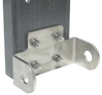
17 12. Locate the stainless steel Antenna Hook Mounting Plate, two U-Bolt Saddle blocks, two stainless steel U-Bolts, four stainless steel 3/8" flat washers, four stainless steel 3/8" split lock washers and four stainless steel 3/8"-16 hex head nuts. Loosely assemble (one or two threads beyond the end of the hex nuts) the two U-Bolts and associated hardware to the antenna hook mounting plate as shown below. The U-Bolts will be tightened in the next assembly step. 13. Loosen the U-Bolts enough to slide the Antenna Hook Mount assembly over the 3" OD antenna lower element on the base assembly. Position the antenna hook mount approximately 1/2" above the insulated channel as shown below


18 14. Tighten the two U-Bolt clamps hardware evenly so the length of the exposed threads is approximately equal. Any clamp should be tightened evenly from side-to-side with an equal amount of thread above each nut. 15. Locate the 1/4"-20 x 1" long stainless steel hex bolt, three 1/4" stainless steel external tooth lock washers, two 1/4" stainless steel flat washers and two 1/4"-20 stainless steel hex nuts. Install the feedpoint hardware at the bottom of the 3" OD bottom element in the pre-drilled hole as shown below. Views showing the Feedpoint hardware installed


19 Mounting and using the Optional DXE-VRW-1 Manual Winch 1. Follow the instructions included with the optional DXE-VRW-1 - Manual Winch Add-On Kit to prepare the Manual Winch for installation on the antenna base assembly. 2. Included with optional DXE-VRW-1 - Manual Winch Add-On Kit is the stainless steel hardware for mounting the winch on the pivot base assembly. The hardware includes three 3/8"- 16 x 1" long stainless steel hex bolts, six stainless steel 3/8"-16 flat washers and three 3/8"-16 Stainless Steel Nyloc Nuts. Loosely install the three sets of stainless steel hardware on the manual winch as shown below. The hardware does not have to be removed from the manual winch to either install or remove the manual winch from the winch mounting plate


20 There are three holes with slots in the mounting bracket. The flat washers will fit through the large holes. Once in place, push the winch inward (toward the antenna elements) allowing the three bolts to go into the three slots. Tighten the hardware to hold the winch in place. Connect the Hook from the manual winch strap to the Antenna Hook Mount as shown below. To remove the winch, simply reverse this sequence

21 3. To lower the antenna, ensure the winch hook is in the Antenna Hook Mount. Remove the four bolts and hardware that hold the Pivot Lock Plate to the Pivot Base Winch Mount Plate. You can now use the winch to pivot the antenna downward. Four Bolts to be removed to allow for pivoting 4. Turn the crank on the manual winch to lower, or raise the antenna. After raising the antenna completely, make sure you replace the four bolts that were removed in step 3. The manual winch should be removed when not in use to protect the gears and web strap from weather and environmental effects. Note: Sawhorses, chairs, or ladders should be used to support the vertical sections during assembly with the pivot base and whenever the vertical is tilted down to allow easy maintenance, or when making adjustments
22 General Information about Aluminum Tubing Note: DXE-P8A -Penetrox A Anti-Oxidant should be used between all antenna element sections. Penetrox is an electrical joint compound to affect a substantial electrical connection between metal parts such as telescoping aluminum tubing or other antenna pieces. It ensures high conductivity at all voltage levels by displacing moisture and preventing corrosion or oxidation Note: UMI Never-Seez or DXE-NSBT8 Anti-Seize should be used on all clamps, bolts and stainless steel threaded hardware to prevent galling and to ensure proper tightening. When assembling any telescoping aluminum tubing sections you should take the following steps: 1. Make sure the edges are smooth and not sharp. Deburring may be necessary, since burrs and shavings can occur on seams as well as edges. All surfaces need to be completely smooth to allow easy assembly of tubing sections. Caution Aluminum tubing edges can be very sharp. Take precautions to ensure you do not get accidentally cut. The raised particles and shavings that appear when the aluminum tubing is machined are referred to as burrs, and the process by which they are removed is known as deburring. Deburring is a finishing method used in manufacturing. Our aluminum tubing is machine cut on both ends and machine slit on one end. Although DX Engineering manufactured aluminum tubing is deburred, you should further assure that there are no ragged edges or protrusions. Use the DXE Slim Grip Deburring Tool, or the DXE Deburring Tool with Extending Handle and Extra Blades for this operation. 2. Clean the inside of the aluminum tubing to clear out any dirt or foreign material that would cause the aluminum tubing sections to bind during assembly. Do not use any type of oil or general lubricant between the aluminum tubing sections. Oils or general lubricants can cause poor electrical connections for radio frequencies. 3. Clean the outside of the aluminum tubing to clear any dirt or foreign material that would cause the clamps to malfunction during assembly. 4. The use of DXE-P8A Penetrox A is highly recommended. Penetrox A is an electrical joint compound which effects a substantial electrical connection between metal parts such as telescoping aluminum tubing or other antenna pieces. Using Penetrox A assures high conductivity at all voltage levels by displacing moisture and preventing corrosion or oxidation. 5. When assembling the aluminum tubing sections, ensure the area is clear of grass, dirt or other foreign material that could cause problems during assembly of the closely fitted telescoping sections
23 Assembling the Vertical Sections Note: DXE-P8A -Penetrox A Anti-Oxidant should be used between all antenna element sections. Penetrox is an electrical joint compound to affect a substantial electrical connection between metal parts such as telescoping aluminum tubing or other antenna pieces. It ensures high conductivity at all voltage levels by displacing moisture and preventing corrosion or oxidation Note: UMI Never-Seez or DXE-NSBT8 Anti-Seize should be used on all clamps, bolts and stainless steel threaded hardware to prevent galling and to ensure proper tightening. The vertical sections of the DXE-7580-VA-1 consists of ten sections of custom engineered 6063 corrosion-resistant aluminum tubing ranging in size from 3" OD to 1" OD. The 3" OD section has already been mounted in the Pivot Base Assembly. A special custom insulator is installed which electrically isolates the 75 meter and 80 meter sections of the antenna. Around this insulator, the heavy duty pre-tuned 75/80 coil assembly is installed. Topping off the installation of the vertical sections will be the optional DXE-7580-THK CW Optimizer Capacity Hat Kit for 75/80 and 80/40 Antennas which is specifically designed to allow the center of resonance to be moved down to the low band edge for dedicated CW ops. The DXE THK consists of hub and 48" adjustable rods. Easy to add to or remove from upper antenna mast with two studded element clamps after lowering antenna. It is suggested that the vertical elements be laid out in a line according to size on a flat surface for ease of assembly. Once all the parts are assembled, the vertical sections should be supported with either saw horses, chairs or other suitable structures for assembly of the 75/80 coil and capacity hat. When all the vertical element sections are assembled, they will be mated to the Pivot Base Assembly. 1. Locate the parts needed for the vertical element assembly: Vertical Elements Assembly Parts List QTY Description QTY Description " OD x 48" long,.120 wall, 8 drilled holes 1 DXE-ECL-10SS Stainless Steel Element Clamp 1 2.5" OD x 72" long,.120 wall, 8 drilled holes 1 DXE-ECL-12SS Stainless Steel Element Clamp " OD x 72" long,.120 wall, 8 drilled holes 3 DXE-ECL-16SS Stainless Steel Element Clamp 1 2" OD x 72" long,.120 wall, 4 drilled holes, slits on one end 2 DXE-ECL-20SS Stainless Steel Element Clamp " OD x 72" long,.120 wall, slits on one end 2 DXE-ECL-24SS Stainless Steel Element Clamp 1 1.5" OD x 72" long,.120 wall, slits on both ends 2 1/4" x 2-34" long Stainless Steel Hex Head Bolt " OD x 72" long,.058 wall, slits on one end 2 1/4" x 3" long Stainless Steel Hex Head Bolt " OD x 72" long,.058 wall, slits on one end 2 1/4" x 3-1/4" long Stainless Steel Hex Head Bolt 1 1" OD x 72" long,.058 wall, slits on one end 2 1/4" x 3-1/2" long Stainless Steel Hex Head Bolt 1 Black Vinyl Cap for 1" OD Tube 16 1/4" Stainless Steel Flat Washer 1 Heavy Duty Insulator, 1.25"/1.5" DIA x 9" long 8 1/4" Stainless Steel Nyloc Hex Nut

24 DXE-7580VA-1 Element Sections: Note: The 3" OD x 72" long,.120 wall thickness base antenna section has already been installed on the Pivot Base Assembly
25 2. Locate the following hardware: QTY Description 2 1/4" x 2-34" long Stainless Steel Hex Head Bolt 2 1/4" x 3" long Stainless Steel Hex Head Bolt 2 1/4" x 3-1/4" long Stainless Steel Hex Head Bolt 12 1/4" Stainless Steel Flat Washer 6 1/4" Stainless Steel Nyloc Hex Nut 3. The diagram to the right is an overall layout of all the vertical elements with hardware and placement of the optional capacity hat bracket are shown for reference. The 3" OD element which is already mounted on the base pivot assembly is shown for reference


26 4. Assemble the 2.5" OD element to the 2.75" OD element using the two stainless steel 3-1/4" long 1/4" bolts, four stainless steel flat washers and two 1/4" stainless steel Nyloc nuts as shown below. When tightening the bolt and Nyloc Nut, tighten them enough to hold, but not tight enough to deform the aluminum elements. 5. Repeat the above step to mate the 2.25" OD element to the 2.5" OD element using the 3" long 1/4" bolts. 6. Repeat the above step to mate the 2" OD element to the 2.25" OD element using the 2-3/4" long 1/4" bolts

27 7. Using a tape measure and felt tip pen, four of the 72" long slit tubing elements need to be marked as follows: The 1.75" OD element is marked 16" from the end without the slit. The 1.25" OD element is marked 4" from the end without the slit. The 1.125" OD element is marked 4" from the end without the slit. The 1" OD element is marked 20" from the end without the slit. 8. Element Clamps are installed approximately 1/4" to 1/2" below the end of the slit tube with the worm tightening drive located between two of the four slits as shown below

28 9. The five slit elements are installed using Stainless Steel Element Clamps. The drawing below shows the exposed lengths for reference. The reference drawing below shows the hardware used for joining the slit elements. 10. Locate two DXE-ECL-24SS Stainless Steel Element Clamps, one DXE-ECL-20SS Stainless Steel Element Clamp and the 1.75" OD x 72" element that was marked in step 7. Slide the two DXE-ECL-24SS element clamps over the 2" OD element. Slide the one DXE-ECL-20SS element clamp over the 1.75" OD element. Slide the 1.75" OD element inside the 2" OD element to the mark made at 16". Tighten the two DXE-ECL-24SS clamps in place. Do not over-tighten which may cause clamp damage. This tubing joint uses a second clamp to ensure proper element position. Slide the DXE-ECL-20SS next to the joint between the 2" OD element and 1.75" OD element. Tighten the clamp in place. This third clamp ensures that the 1.75" section cannot slip further inside the 2" OD section


29 11. Locate the Insulator, one DXE-ECL-20SS Stainless Steel Element Clamp, one DXE-ECL- 16SS Stainless Steel Element Clamp and the 1.5" OD x 72 long element that has slits at both ends. Slide the DXE-ECL-20SS over the 1.75" OD element. Slide the DXE-ECL-16SS over the 1.5" OD element. The larger diameter end of the insulator fits inside the 1.75" OD element. The smaller diameter side fits inside the 1.5" OD element. Position the element clamps over the slits and tighten as shown below. 12. Locate two DXE-ECL-16SS Stainless Steel Element Clamps, one DXE-ECL-12SS Stainless Steel Element Clamp and the 1.25" OD x 72" element that was marked in step 7. Slide the two DXE-ECL-16SS element clamps over the 1.5" OD element. Slide the one DXE-ECL-12SS element clamp over the 1.25" OD element. Slide the 1.25" OD element inside the 1.5" OD element to the mark made at 4". Tighten the two DXE-ECL-16SS clamps in place. Do not overtighten which may cause clamp damage. This tubing joint uses a second clamp to ensure proper element position. Slide the DXE-ECL-12SS next to the joint between the 1.5" OD element and 1.25" OD element. Tighten the clamp in place. This third clamp ensures that the 1.25" section cannot slip further inside the 1.5" OD section. 13. Locate the DXE-ECL-12SS Stainless Steel Element Clamp and the 1.125" OD x 72" element that was marked in step 7. Slide the DXE-ECL-12SS element clamp over the 1.125" OD element. Slide the 1.125" OD element inside the 1.25" OD element to the mark made at 4". Tighten the DXE-ECL-12SS clamp in place
30 14. Locate the DXE-ECL-10SS Stainless Steel Element Clamp, the 1" OD x 72" element that was marked in step 7 and the Black Vinyl Cap. Slide the DXE-ECL-10SS element clamp over the 1.125" OD element. Slide the 1" OD element inside the 1.125" OD element to the mark made at 20". Tighten the DXE-ECL-10SS clamp in place. Install the black vinyl cap on the top end of the 1" OD element. Once mounted to the 3" OD base element section, the overall length prior to final tuning will be 637" or 53 feet, 1 inch


31 Mating the Vertical Element to the Pivot Base Assembly 1. To lower the antenna, ensure the winch hook is in the Antenna Hook Mount. Remove the four bolts and hardware that hold the Pivot Lock Plate to the Pivot Base Winch Mount Plate. You can now use the winch to pivot the antenna downward. Four Bolts to be removed to allow for pivoting 2. Locate the 3-1/4" long 1/4" bolts, four stainless steel flat washers and two 1/4" stainless steel Nyloc nuts. Align the 3" OD base section element with the assembled vertical elements. Slide the 2.75" element section into the 3" OD base element section aligning the 4 holes


32 3. Assemble the 2.75" OD element to the 3" OD element using the two stainless steel 3-1/4" long 1/4" bolts, four stainless steel flat washers and two 1/4" stainless steel Nyloc nuts as shown below. When tightening the bolt and Nyloc Nut, tighten them enough to hold, but not tight enough to deform the aluminum elements. DANGER: When raising or lowering the vertical antenna make sure you have not inadvertently located the antenna underneath power lines. Residential power lines are often less than 40' high. Contact With Any Power or Utility Lines Can Be Lethal! 75/80 Coil Assembly and Installation The 75/80 meter Coil Assembly is pre-wound. The assembly is mounted to the vertical antenna straddling where the insulator is installed when the antenna is lowered. Mounting is accomplished using three studded element clamps and two brackets with stainless steel hardware. 75/80 Coil Assembly QTY Description 1 Custom 75/80 Coil Assembly 2 DXE-ECLS " Studded Element Clamp 1 DXE-ECLS " Studded Element Clamp 1 Straight Bracket 1 "T" Bracket 6 #10-24 Stainless Steel Hex Nuts 5 #10 Stainless Steel External Tooth Star Washer 5 #10 Stainless Steel Flat Washer 5 #10 Stainless Steel Split Washer


33 1. Install two 1.75" studded clamps on the "T" Bracket using the two #10 stainless steel external tooth lock washers, two #10 stainless steel flat washers, two #10 stainless steel split washers, and the two stainless steel hex nuts as shown. 2. Install one 1.5" studded clamp on the Straight Bracket using one #10 stainless steel external tooth lock washer, one #10 stainless steel flat washer, one #10 stainless steel split washer, and two stainless steel hex nuts as shown. 3. Install the "T" bracket and straight bracket on the 75/80 coil using the #10 stainless steel external tooth lock washers, #10 stainless steel flat washers, #10 stainless steel split washers, and stainless steel hex nuts as shown

 to allow easy installation of the 75/80 coil assembly on the antenna in the")

34 4. Using a small Phillips screwdriver, connect the Tap Coil to the middle of the coil. This will be moved as needed during tuning. 5. Unscrew (or open) the three element clamps (two 1.5" and one 1.75" clamps) to allow easy installation of the 75/80 coil assembly on the antenna in the next step. 6. Install the 75/80 coil assembly to the vertical antenna by straddling the insulator with the clamps as shown below. 7. Once in place and aligned parallel to the antenna elements, tighten all the element clamps securely


.")


35 Base Matching Network Assembly and Installation Base Matching Network Assembly QTY Description 1 Custom made base loading coil assembly with wire & Coil Tap Clip 1 1/4" Flat Washer 1 1/4" Split Lock Washer 1 1/4"-16 Nut 1. Use a small Phillips head screwdriver to loosen the tap clip screw and position the tap clip on the 6th or 7th turn on the coil as shown (this will be re-adjusted during tuning). Attach the Base Matching Network Assembly to the optional DXE-RADP-3 Radial Plate using the 1/4" flat washer, 1/4" split lock washer and 1/4-16 hex nut as shown below. Verify the wires and coax will not be in the way when pivoting the antenna. 2. Install the optional DXE-363-SST - Bulkhead Fitting to the radial plate and the Connect the PL The other wire with the ring terminal from the coil is connected to the feedline connection point on the antenna base section

36 Optional Capacity Hat Assembly and Installation This add-on kit for the DXE-7580VA-1 high performance THUNDERBOLT TM vertical antenna allows the center of resonance to be moved down to the low band edge for dedicated CW operations. If you do not install it, skip this section and proceed to the Tuning section of this manual. The drawing to the right shows the optional Capacity Hat parts for reference. Also included in this kit is one 5/64" Allen Wrench and one spare 1/8" and one spare 1/4" long stainless steel Allen Screws


37 1. Locate the two 1-1/4" studded element clamps, the Top Hat "L" Bracket, two #10 stainless steel star washers, two #10 stainless steel split washers, two #10 stainless steel washers and two #10 stainless steel hex nuts. Assemble the studded element clamps to the "L" bracket as shown below. 2. Locate the 1/2" Mast Tube Connector Fitting, one 3/" stainless steel flat washer, one 3/8" stainless steel split lock washer, and one 3/8-24 stainless steel hex nut. Assemble the mast tube connector fitting to the "L" bracket as shown below. 3. Install the "L" bracket to the vertical antenna on the 1.125" OD element, just above the 1.25" OD element as shown below. Tighten the studded element clamps to hold the assembly in place


38 4. Locate the Smooth Hub and two #8-32 x 1/4" long Stainless Steel Screw -Cup Point Allen screws. Using the supplied 5/64" Allen Wrench screw the 1/4" long Allen screws in the smooth hub in the two places as shown below. Only put these Allen Screws in half way, they will be tightened in a later step. These are the two Allen Screws that hold the smooth hub to the 1/2" mast tube connector fitting. 5. Locate the six smaller Allen screws (1/8" long) and install them loosely in the smooth hub as shown below. These are the Allen Screws that will hold the Hot Rodz TM in place after you adjust their lengths. Insert the Hot Rodz TM in the smooth hub as shown below. Slide them in the smooth hub and adjust their length to be 3 feet. Tighten the appropriate Allen screw to hold them in place. Refer to the pictures below for reference

39 6. Install the Smooth Hub with the Hot Rodz TM on the 1/2" Mast Tube Connector Fitting. Rotate the smooth hub to position the Hot Rodz TM so they are not touching the vertical antenna element. Lock the smooth hub in place by tightening the two long Allen screws that were installed in Step Locate and install the six plastic end caps on the ends of the Hot Rodz TM. Tuning the Vertical Tuning the DXE-7580VA-1 75/80 Meter Vertical Antenna is straightforward and intuitive. If you use an SWR meter or an analyzer at the base of the antenna you will get the most accurate readings in a timely fashion. Since the 2:1 SWR bandwidth of the antenna is approximately 300 khz, the adjustment parameters are relatively broad and fine adjustment is not usually necessary. It is best to start the adjustment process without the Base Matching network connected. See picture on right showing the Base Matching network removed and insulated from the ground radial system. As a result, initial SWR measurements at the feedpoint of the antenna may indicate slightly elevated minimum SWR. This will be reduced substantially when the Base Matching Network is connected. Note: For the purposes of these instructions the term resonance or resonant frequency is defined as the point of lowest SWR and may be used interchangeably

40 As assembled the minimum SWR point for the 75 meter band should be near 3800 khz. The length of the topmost tubing section is adjusted to change the 80M resonant frequency as indicated by the point of lowest SWR. Loosen the 1.125" section clamp and lengthen the top 1" section to move the frequency of the minimum 80 meter SWR lower. Likewise, make the 1 section shorter to make the resonant frequency higher. Be sure to tighten the clamps after making an antenna length adjustment. Adjusting the Tap Coil on the 75/80 Coil Assembly (located at the insulator on the vertical antenna) will vary the resonance. Moving the tap clip upward on the coil (less turns being used) will raise the frequency. Likewise, lowering the tap clip position on the coil (more turns being used) will lower the frequency. Securely tighten the tap clip when done. Reconnect the Matching Network to the Radial Plate. Connect the Tap Clip in the Base Matching Network at the 6th or 7th turn from the top as shown and proceed as follows: Adjust the tap clip by moving the tap clip to a different coil turn on the Base Matching Network Coil for minimum SWR on 80M. Disregard any frequency shift of the points of lowest SWR on this band at this time. Adjust the tap clip by moving the tap clip to a different coil turn on the Base Matching Network Coil for minimum SWR on 80 meters. Disregard any frequency shift of the points of lowest SWR on this band at this time. Recheck the lowest SWR. If the SWR is higher move the tap clip on the Base Matching Network Coil to a position that gives the best SWR on each band. Securely tighten the tap clip when done. Once final tuning is complete and you have verified correct operation on-the-air, both of the coil taps (Base Matching Network - on the Radial Plate, and the 75/80 Coil - on the vertical antenna) should be soldered in place to eliminate any future intermittent connection due to environmental corrosion to the coil taps


41 Operation of the DXE-7580VA-1 for CW portion of the band To optimize the DXE-7580VA-1 for operation near the bottom of the band, add the optional capacity Top Hat Kit model DXE-7580-THK. Assemble the Top Hat and install it at the position shown in the diagram below. Adjust the physical position of the Top Hat on the 1.125" element tube section to achieve resonance on your target frequency. Sliding the Top Hat higher will shift the point of resonance to a lower frequency. The position of the Top Hat Kit rods within the hub will also affect tuning. Shortening the rods or removing some of them will shift the resonant frequency higher. Locking the Pivot Base To help prevent accidental pivoting, ensure the four pivot locking bolts are in place and properly secured. Additionally, you may replace one of the bolts with a padlock to further prevent tampering or accidental pivoting as shown below. Ensure all four Pivot Locking Bolts are in place Padlock used in place of one Pivot Locking Bolt
42 DXE-7580VA-1 Parts List Pivot Base Assembly - US Patent No. 8,130,168 QTY Description 1 Base Side Bottom Hinge 1 Antenna Side Bottom Hinge 2 Bottom Hinge Bushing 1 Heavy Duty Antenna Insulator Channel 2 Saddle Backing Plate 1 Antenna Pivot Hook Mount 1 Pivot Base Winch Mount 2 Pivot Base Plate Bracket 1 Pivot Base Lock Plate 2 Backing Plate 2 Saddle Spacer Plate 4 3" Stainless U-Bolt 4 3" Cast Saddle Clamp 40 3/8" Flat Washer 32 3/8" Split Lock Washer 32 3/8"-16 Nut 8 3/8"-16 x 1.25" Long, Hex Head Cap Screw 4 2"-3" Cast V-Saddle 4 2"-3" 3/8"-16 V-Bolt 8 3/8"-16 x 1-1/2" Long Stainless Steel Carriage Bolt 2 1/2"-13 x 1-1/4" Long Stainless Steel Hex Head Cap Screw 4 1/2" x 1-1/4" Stainless Steel Washer 2 1/2" Stainless Steel Lock Washer 2 1/2"-13 Stainless Steel Nut Optional DXE-VRW-1 Manual Winch Assembly QTY Description Pound Exposed Gear Hand Winch with Brake 1 Custom Polyester web strap with Hook, 2" x 15 Ft 1 3/8-16 x 3-1/2" long Grade 8 Hex Head Bolt 4 3/8-16 Stainless Steel Nyloc Nut 3 3/8-16 x 1" long Stainless Steel Hex Bolt 8 3/8"-16 Stainless Steel Flat Washer Feedpoint Hardware QTY Description 3 1/4" External Star Washer 1 1/4"-20 x 1" long Stainless Steel Hex Head Cap Screw 2 1/4" Stainless Steel Flat Washer 2 1/4" Stainless Steel Nut 1 1/4"-16 Nut
43 Vertical Elements Assembly QTY Description 1 3" OD x 72" long,.120" wall, 5 drilled holes " OD x 48" long,.120 wall, 8 drilled holes 1 2.5" OD x 72" long,.120 wall, 8 drilled holes " OD x 72" long,.120 wall, 8 drilled holes 1 2" OD x 72" long,.120 wall, 4 drilled holes, slits on one end " OD x 72" long,.120 wall, slits on one end 1 1.5" OD x 72" long,.120 wall, slits on both ends " OD x 72" long,.058 wall, slits on one end " OD x 72" long,.058 wall, slits on one end 1 1" OD x 72" long,.058 wall, slits on one end 1 Black Vinyl Cap for 1" OD Tube 1 Heavy Duty Insulator, 1.25"/1.5" DIA x 9" long 1 DXE-ECL-10SS Stainless Steel Element Clamp 1 DXE-ECL-12SS Stainless Steel Element Clamp 3 DXE-ECL-16SS Stainless Steel Element Clamp 2 DXE-ECL-20SS Stainless Steel Element Clamp 2 DXE-ECL-24SS Stainless Steel Element Clamp 2 1/4" x 2-34" long Stainless Steel Hex Head Bolt 2 1/4" x 3" long Stainless Steel Hex Head Bolt 2 1/4" x 3-1/4" long Stainless Steel Hex Head Bolt 2 1/4" x 3-1/2" long Stainless Steel Hex Head Bolt 16 1/4" Stainless Steel Flat Washer 8 1/4" Stainless Steel Nyloc Hex Nut 75/80 Coil Assembly QTY Description 1 Custom 75/80 Coil Assembly 2 DXE-ECLS " Studded Element Clamp 1 DXE-ECLS " Studded Element Clamp 1 Straight Bracket 1 "T" Bracket 6 #10-24 Stainless Steel Hex Nuts 5 #10 Stainless Steel External Tooth Star Washer 5 #10 Stainless Steel Flat Washer 5 #10 Stainless Steel Split Washer Base Matching Network Assembly QTY Description 1 Custom made base loading coil assembly with wire & Coil Tap Clip 1 1/4" Flat Washer 1 1/4" Split Lock Washer 1 1/4"-16 Nut
44 Optional DXE-7580-THK Capacity Hat Assembly QTY Description 1 Smooth Hub 1 0.5" Mast Tube Connector Fitting 7 #8-32 x 1/8" long Stainless Steel Allen Screw -Cup Point 3 #8-32 x 1/4" long Stainless Steel Allen Screw -Flat Point 6 Hot Rodz TM -.125" x 48" Stainless Steel 6 Plastic End Cap,.110" x 1" long 2 Studded Element Clamp, 1-1/4" 2 #10 Stainless Steel Star Washer 2 #10 Stainless Steel Flat Washer 2 #10 Stainless Steel Split Lock Washer 2 #10-24 Stainless Steel Nut 1 3/8" Stainless Steel Flat Washer 1 3/8" Stainless Steel Split Lock Washer 1 3/8-24 Stainless Steel Hex Nut 1 Top Hat 'L' Bracket 1 5/64" Allen Wrench Note: This antenna system is normally shipped in several boxes. The hardware parts maybe in more than one box. The part lists listed above are arranged for ease of assembly. Additional material required, but not supplied: 1. Antenna Mounting Pipe - 2-1/2" Schedule 80 Galvanized steel mounting pipe, (2.895 OD) x 7 feet long minimum (see text for more information) 2. Concrete - For mounting pipe installation (see text for suggestions)


: Made from Laser Cut Stainless Steel with 20 Sets of Stainless Steel Radial Attachment Hardware.")


45 Suggested Parts Not Included DXE-VRW-1 - Manual Winch Add-on Raising Kit Manual winch add-on kit for the High Performance DX Engineering vertical antennas DXE-8040VA-1 and DXE-7580VA-1. The tilt fixtures for these antennas are equipped to accept the winch directly. Allows easy raising and lowering of tall antennas - may be easily moved from one antenna to another in multi-antenna arrays. DXE-7580-THK - CW Optimizer Capacity Hat for 75/80 and 80/40 Antennas This add-on kit for the DXE-8040VA-1 and DXE-7580VA-1 high performance THUNDERBOLT vertical antennas allows the center of resonance to be moved down to the low band edge for dedicated CW ops. Consists of hub and 48" adjustable rods. Easy to add to or remove from upper antenna mast with single bolt after lowering antenna. DXE-RADP-3 - Radial Plate (patented): Made from Laser Cut Stainless Steel with 20 Sets of Stainless Steel Radial Attachment Hardware. The DX Engineering Radial Plate is meant for those of you having a vertical antenna and want an easy, neat and effective way to connect those essential radial wires to your antenna system for the highest efficiency and strongest signals. DXE-SSVC-3P - Stainless Steel V-Clamp for 2 to 3 inch steel pipe This V-Clamp is made in one size that fits Steel tubing or pipe from 2 to 3'' OD as used in antenna construction. The supplied V-bolt is long enough to attach tubing to thick plates and is made with anti-corrosive properties. The special Stainless Steel saddle has serrated teeth will clamp to the pipe securely by biting into the surface. For this reason, it is not recommended for softer aluminum tubing or pipe. U-Bolt thread dimensions: 3/8"-16 x 1.75". V-bolt and saddle made from high-strength 18-8 stainless steel DXE-RADP-1HWK - Radial Plate Wire Attachment Hardware Kit Additional 20 Sets of ALL Stainless Steel Radial Hardware for use with the DX Engineering Stainless Steel Radial Plate. (20) 1/4'' Bolts - (20) 1/4'' Nuts - (20) 1/4'' Flat Washers (20) 1/4'' Split Washers - (20) 1/4'' Star Washers DXE-363-SST - Bulkhead Fitting, SO-239 Socket, Silver Plating, Teflon Insulation This hi-quality bulkhead connector uses silver plated outer and inner conductors and a Teflon insulator. The connector has very low loss and high electrical break down. It comes with two nuts to secure the connector to our radial plate or other flat surface. Perfect for use with the DX Engineering Radial Plate, (DXE-RADP-3) it ensures the radial ground system, the antenna ground and the feedline shield are common. It can also be used in other coaxial applications where the male ends (PL-259) of 2 coax cables need to be connected, such as when joining two pieces of coax together. Don't forget to waterproof coaxial connections. Silver plated, Teflon insulated, Very low loss, High electrical break down 2 in. long


46 Optional Accessory Items UMI-81343, DXE-NSBT8 - Anti-Seize & Never-Seez An Anti-seize compound MUST be used on any Stainless Steel nuts, bolts, clamps or other hardware to prevent galling and thread seizure. Any of these products can be used for this purpose. *UMI Anti-Seize, 1 oz. Squeeze Tube *UMI Anti-Seize, 8.5 oz. Aerosol Can *DXE-NSBT8 Never-Seez, 8 oz. Brush Top *DXE-NMBT8 Never-Seez, 8 oz. Brush Top, Marine Grade * These products are limited to domestic UPS Ground shipping only DXE-P8A - Penetrox A Anti-Oxidant - 8 oz Squeeze Bottle Use Penetrox A electrical joint compound to affect a substantial electrical connection between metal parts such as telescoping aluminum tubing or other antenna pieces. Ensures high conductivity at all voltage levels by displacing moisture and preventing corrosion or oxidation. For Aluminum to Aluminum, Aluminum to Copper, or bare conductors. Not recommended for use with rubber or polyethylene insulated wire. 8 oz. squeeze bottle * This product is limited to domestic UPS Ground shipping only DXE-RADW - 500K or 1000K Radial Wire Kits and Components To achieve optimal performance with a ground-mounted vertical, install as many radials as possible. These bulk radial wire kits use insulated wire that is UV resistant, hard to see and lays down easily, unlike the wire that is commonly available at the big box stores. It will last much longer in contact with soil than bare wire. The DXE-RADW- 500K or 1000K kit provide everything you will need to build the perfect radial system! 500/1000 ft. spool of 14 AWG, stranded copper wire with vinyl insulation 20/40 lugs 100/200 radial wire anchor pins- Eliminating the need to bury your radials! Build up to 20/40 radials, 25 feet long DXE-RADW-500K Bulk Radial Wire Kit, 500 ft Spool of Wire, 20 Lugs, 100 Staples DXE-RADW-1000K Bulk Radial Wire Kit, 1000 ft Spool of Wire, 40 Lugs, 200 Staples DXE-RADW-500KBD or 1000KBD - Bulk Radial Wire Kits and Components To achieve optimal performance with a ground-mounted vertical, install as many radials as possible. These bulk radial wire kit use insulated wire that is UV resistant, hard to see and lays down easily, unlike the wire that is commonly available at the big box stores. It will last much longer in contact with soil than bare wire. The biodegradable anchors allow easy installation of radial wires, and will degrade and disappear in a year or so when they are no longer needed. The DXE-RADW-500 or 1000KBD kit provide everything you will need to build the perfect radial system! 500/1000 ft. spool of 14 AWG, stranded copper wire with vinyl insulation 20/40 lugs 100/200 biodegradable radial wire anchor pins- Eliminating the need to bury your radials! Build up to 20/40 radials, 25 feet long DXE-RADW-500KBD DXE-RADW-1000KBD Bulk Radial Wire Kit, 500 ft Spool of Wire, 20 Lugs, 100 Biodegradable Staples Bulk Radial Wire Kit, 1000 ft Spool of Wire, 40 Lugs, 200 Biodegradable Staples DXE-225RT-20 - Ring terminal Wire Gauge, 1/4" hole/20 Pack \his is a set of 20 ring terminals for AWG #14 to #16 wire with a clearance hole for a 1/4" bolt. These are the same crimp terminals supplied with the DXE Radial Wire Kits for #14 Radial and Antenna Wire


, 65 Ft (-65RT) DXE-RADW-20RT DXE-RADW-32RT DXE-RADW-65RT Package of 20 each 20 Ft Radials with 1/4\" Ring Terminals Package of 20 each 32 Ft Radials with 1/4\" Ring Terminals Package of 20")

. Depending on the weather conditions, they will degrade in about a year.")
47 DXE-RADW-20RT/-32RT/-65RT Pre-Assembled, Radial Wire, w/ 1/4" ring Terminals, 20 Pack The DXE-RADW Radial Wire Kits include the highest quality 14 gauge stranded copper wire with a relaxed black PVC insulation for easy installation of your radial system. They allow fast and easy installation of your radial ground system, and permit you to mix and match different length to fit the available space. The stranded wire and relaxed insulation mean that the wire will lay flat as you place it on the ground - easy to install! The twenty pre-cut radial wires include 1/4" ring terminals professionally crimped on one end for quick and easy attachment to the radial plate. These Radial Wire Kits are designed for users of vertical antenna systems which have the need for a high quality radial system for optimum antenna performance. The 1/4" ring terminals are machine crimped for maximum grip. Soldering is not required for strength, but is recommended if installed in corrosive environments such as salt spray. Packed 20 Radial Wires per package 14 gage, stranded copper wire Black relaxed PVC insulation 1/4" Ring Terminal professionally crimped on each Radial Wire 3 lengths to choose from: 20 Ft (-20RT), 32 Ft (-32RT), 65 Ft (-65RT) DXE-RADW-20RT DXE-RADW-32RT DXE-RADW-65RT Package of 20 each 20 Ft Radials with 1/4" Ring Terminals Package of 20 each 32 Ft Radials with 1/4" Ring Terminals Package of 20 each 65 Ft Radials with 1/4" Ring Terminals DXE-STPL - Radial Wire Anchor Pins, 100/pack - No need to bury your radials! DX Engineering Radial Wire Anchor Pins are perfect for fastening radials below the grass line to eliminate the risk of damaging your radials during lawn maintenance. 100 count - 6'' Pins 11-Gauge DXE-STPL-100P Radial Wire Anchor Pins, 100/pack DXE-STPL-300P Radial Wire Anchor Pins, 300/pack DXE-STPL-100BD - Radial Wire Staple, Biodegradable, 3", 100 pack DX Engineering DXE-STPL-100BD is a 100-pack of 3 biodegradable anchors that are produced from recycled PLA (Polylactide Resin). Depending on the weather conditions, they will degrade in about a year. They are easily installed and will hold radial wires in place until lawn roots overtake them - and then disappear. Ecologically friendly! SUM Automatic Wire Stripper/Crimper/Cutter, Ga. Our wire stripper uses a spring-loaded design to make quick work of wires ranging from 24 to 10 gauge. Just insert the wire, squeeze the handle, and listen for the click. That s the sound of another perfect wire stripping job performed in about 2 seconds - a fraction of the time it takes your pocket knife to do the same job. An adjustable wire length guide helps you make uniform strips, and a built-in wire cutter and crimper helps you complete your wiring job. Spring-loaded design Strips wires ranging from 24 to 10 gauge built-in wire cutter and crimper DXE-3M2155-3M Temflex 2155 Rubber Splicing Tape. Conformable self-fusing rubber electrical insulating tape. It is designed for low voltage electrical insulating and moisture sealing applications. For outdoor use, it should be protected from UV deterioration with an overwrap of TRM TRM Scotch Super 33+. Highly conformable super stretchy tape for all weather applications. This tape provides flexibility and easy handling for all around performance. It also combines PVC backing with excellent electrical insulating properties to provide primary electrical insulation for splices up to 600V and protective jacketing

48 Technical Support If you have questions about this product, or if you experience difficulties during the installation, contact DX Engineering at (330) You can also us at: For best service, please take a few minutes to review this manual before you call. Warranty All products manufactured by DX Engineering are warranted to be free from defects in material and workmanship for a period of one (1) year from date of shipment. DX Engineering s sole obligation under these warranties shall be to issue credit, repair or replace any item or part thereof which is proved to be other than as warranted; no allowance shall be made for any labor charges of Buyer for replacement of parts, adjustment or repairs, or any other work, unless such charges are authorized in advance by DX Engineering. If DX Engineering s products are claimed to be defective in material or workmanship, DX Engineering shall, upon prompt notice thereof, issue shipping instructions for return to DX Engineering (transportation-charges prepaid by Buyer). Every such claim for breach of these warranties shall be deemed to be waived by Buyer unless made in writing. The above warranties shall not extend to any products or parts thereof which have been subjected to any misuse or neglect, damaged by accident, rendered defective by reason of improper installation, damaged from severe weather including floods, or abnormal environmental conditions such as prolonged exposure to corrosives or power surges, or by the performance of repairs or alterations outside of our plant, and shall not apply to any goods or parts thereof furnished by Buyer or acquired from others at Buyer s specifications. In addition, DX Engineering s warranties do not extend to other equipment and parts manufactured by others except to the extent of the original manufacturer s warranty to DX Engineering. The obligations under the foregoing warranties are limited to the precise terms thereof. These warranties provide exclusive remedies, expressly in lieu of all other remedies including claims for special or consequential damages. SELLER NEITHER MAKES NOR ASSUMES ANY OTHER WARRANTY WHATSOEVER, WHETHER EXPRESS, STATUTORY, OR IMPLIED, INCLUDING WARRANTIES OF MERCHANTABILITY AND FITNESS, AND NO PERSON IS AUTHORIZED TO ASSUME FOR DX ENGINEERING ANY OBLIGATION OR LIABILITY NOT STRICTLY IN ACCORDANCE WITH THE FOREGOING. DX Engineering 2012 DX Engineering, DXE, Hot Rodz, Maxi-Core, THUNDERBOLT, Antenna Designer, Yagi Mechanical, and Gorilla Grip Stainless Steel Boom Clamps, are trademarks of PDS Electronics, Inc. No license to use or reproduce any of these trademarks or other trademarks is given or implied. All other brands and product names are the trademarks of their respective owners. Specifications subject to change without notice
80 and 40 Meter DX Engineering Thunderbolt Dual Band Vertical Antenna
 80 and 40 Meter DX Engineering Thunderbolt Dual Band Vertical Antenna DXE-8040VA-1 US Patent No. 8,130,168 DXE-8040VA-1-INS Revision 4e DX Engineering 2013 1200 Southeast Ave. - Tallmadge, OH 44278 USA
75/80 Meter Full Size Quarter-Wave Vertical Antenna
 75/80 Meter Full Size Quarter-Wave Vertical Antenna DXE-7580FS-VA-2 US Patent No. 8,139,168 DXE-7580FS-VA-2-INS Revision 4 DX Engineering 2012 P.O. Box 1491 Akron, OH 44309-1491 USA Phone: (800) 777-0703
160 Meter Thunderbolt Vertical Antenna
 160 Meter Thunderbolt Vertical Antenna DXE-160VA-1 DXE-160VA-1-INS Revision 2 US Patent No. 8,130,168 [Wires and ropes were enhanced in this photograph so they would show up] DX Engineering 2016 1200 Southeast
75/80 Meter Full Size Quarter-Wave Vertical Antenna
 75/80 Meter Full Size Quarter-Wave Vertical Antenna DXE-7580FS-VA-2 US Patent No. 8,130,168 DXE-7580FS-VA-2-INS Revision 6a DX Engineering 2017 1200 Southeast Ave. - Tallmadge, OH 44278 USA Phone: (800)
Vertical Antenna Tilt Base Assembly
 Vertical Antenna Tilt Base Assembly DXE-VA-BASE DXE-VA-BASE-INS Rev. 5c (DXE-VA-BASE shown with customer supplied mounting pipe and antenna section) DX Engineering 2010 P.O. Box 1491 Akron, OH 44309-1491
40-30 Meter Vertical Antenna
 40-30 Meter Vertical Antenna DXE-4030VA-1 DXE-4030VA-1-INS-Revision 3g DX Engineering 2013 P.O. Box 1491 Akron, OH 44309-1491 USA Phone: (800) 777-0703 Tech Support and International: (330) 572-3200 Fax:
CW Optimizer Capacity Hat Kit. 75/80 and 80/40 Thunderbolt Vertical Antennas. for the DXE-7580-THK
 CW Optimizer Capacity Hat Kit for the 75/80 and 80/40 Thunderbolt Vertical Antennas DXE-7580-THK DXE-7580-THK-INS Revision 1a DX Engineering 2012 P.O. Box 1491 Akron, OH 44309-1491 USA Phone: (800) 777-0703
40/30 Meter Dual-Band Vertical Antenna
 40/30 Meter Dual-Band Vertical Antenna DXE-4030VA-1 DXE-4030VA-1-INS-Revision 5 DX Engineering 2016 1200 Southeast Ave. - Tallmadge, OH 44278 USA Phone: (800) 777-0703 Tech Support and International: (330)
30 Meter Add-On Kit for the DXE-8040VA-1 Vertical Antenna
 30 Meter Add-On Kit for the DXE-8040VA-1 Vertical Antenna DXE-8040-30AOK DXE-8040-30AOK-INS Revision 0d DX Engineering 2017 1200 Southeast Ave. - Tallmadge, OH 44278 Phone: (800) 777-0703 Tech Support
Tilt Base Mounting Plate Installation Guide
 Tilt Base Mounting Plate Installation Guide DXE-TB-INS-Rev 3f U.S. Patent 7,432,875 DXE-TB-3P Shown with optional Hustler BTV Series Antenna installed and partially tilted DXE-TB-3P for Hustler 4/5/6-BTV
12 Meter Add-On Kit for the Hustler 4/5/6-BTV Vertical Antennas
 12 Meter Add-On Kit for the Hustler 4/5/6-BTV Vertical Antennas DXE-AOK-12M Patent Pending DXE-AOK-12M-INS Revision 1d DXE-AOK-12M Installed on a BTV with optional Tilt Base and Direct Coax Feedpoint DX
Multi-Band Vertical Remote Antenna Tuner Add-on Kit for 43 Foot Multi-band Vertical Antennas Meters
 Multi-Band Vertical Remote Antenna Tuner Add-on Kit for 43 Foot Multi-band Vertical Antennas 80-10 Meters DXE-MBV-ATU-1 DXE-MBV-ATU-1-INS Revision 3c DX Engineering 2012 P.O. Box 1491 Akron, OH 44309-1491
MULTI-POLE MOUNT MULTI-POLE MOUNT. Assembly Instructions. Assembly Instructions. step-by-step assembly and installation
 MULTI-POLE MOUNT Assembly Instructions MULTI-POLE MOUNT Assembly Instructions step-by-step assembly and installation PCN 062411-2 The Multi-Pole Mount A few words about the product The Multi-Pole Mount
Auto Tuned Multi-Band HF Stealth Antenna System DXE-ATSA-1
 Auto Tuned Multi-Band HF Stealth Antenna System DXE-ATSA-1 DXE-ATSA-1-INS Revision 0d DXE-ATSA-1 shown with optional DXE-SA80-AOK DX Engineering 2017 1200 Southeast Ave. - Tallmadge, OH 44278 USA Phone:
INSTRUCTION MANUAL_. Specifications. Electrical.
 308 Industrial Park Road Starkville, MS 39759 USA Ph: (662) 323-9538 FAX: (662) 323-6551 DX-77A 7-Band HF Vertical 10, 12, 15, 17, 20, 30, 40-Meter INSTRUCTION MANUAL_ General Description The "DX-77-A"
MULTI-POLE MOUNT - G2 ASSEMBLY INSTRUCTIONS. step-by-step assembly and installation. Version 1, Rev D SP PCN
 MULTI-POLE MOUNT - G2 ASSEMBLY INSTRUCTIONS step-by-step assembly and installation Version 1, Rev D SP3287-2 PCN 042412-1 The Multi-Pole Mount - G2 A few words about the product The Multi-Pole Mount -
MULTI-POLE MOUNT LARGE GROUND MOUNT. Assembly Instructions. Assembly Instructions. step-by-step assembly and installation
 MULTI-POLE MOUNT Assembly Instructions LARGE GROUND MOUNT Assembly Instructions step-by-step assembly and installation PCN 081711-2 The Large Ground Mount A few words about the product The Large Ground
Accessories. Introduction. Cable Hangers LINE PRODUCTS TRANSMISSION
 Accessories Introduction While a number of cable related accessories are available on the market, RFS components are of the highest quality and are designed to provide years of trouble-free service. Together
PLP Compression Dead-end & Jumper Terminal for ACSR & ACSS Conductors
 MARCH 2017 PLP Compression Dead-end & Jumper Terminal for ACSR & ACSS Conductors Be sure to read and completely understand this procedure before applying product. Be sure to select the proper PREFORMED
IRS-151 INSTALLATION INSTRUCTIONS `55-57 CHEVY INDEPENDENT REAR SUSPENSION
 IRS-151 INSTALLATION INSTRUCTIONS `55-57 CHEVY INDEPENDENT REAR SUSPENSION Please read these instructions completely before starting your installation. Remember the basic rule for a successful installation:
THE AquaBlast & RocketRide FUNSLIDES
 THE AquaBlast & RocketRide FUNSLIDES ASSEMBLY AND INSTALLATION INSTRUCTIONS * * C A U T I O N * * S.R. SMITH AquaBlast TM & RocketRide TM FUNSLIDES TM ARE MANUFACTURED FOR INSTALLATION AND USE ON RESIDENTIAL
Assembly & Installation Instructions
 TM P R O D U C T S Assembly & Installation Instructions FOR 28 SERIES SNOWPLOW PIVOT ASSEMBLY AND FLOAT LIMITER 99103000 FOR SERIAL NUMBERS 28D100000 TO 28D100770 97100552A 1. THINK SAFETY, ALWAYS WEAR
Installation Instructions
 Installation Instructions Product: SwitchBlade Swaybar System Part Number: PN 9100 Application: Jeep Wrangler TJ, 1997-06 (front) Welcome CONGRATULATIONS on purchasing a SwitchBlade Swaybar System from
Installation Instructions Unimatic Shifter
 Installation Instructions Unimatic Shifter Universal Shifter for Automatic Transmissions Part Number 80775 2000 by B&M Racing & Performance Products LLC The B&M Unimatic is a universal shifter that will
920 Remote Control Switches
 920 Remote Control Switches REMOTE CONTROL SWITCHES Service Bulletin This service bulletin for ASCO 920 Remote Control Switches explains how to replace the main s, operator coil, control s, and how to
Rostselmash Torum 740
 Note: Indented items indicate parts included in an assembly listed above Quantity by Model Part Name/Description Part Number 740 Combine Kit Torum 740 4100762 1 Threaded Arm Assembly 2000311-2 1 Header
Owner smanual. Banks TorqueTube System Ford 5.4L F-150 (Late Body Style) with Installation Instructions
 with Installation Instructions") Owner smanual with Installation Instructions Banks TorqueTube System 2004-2008 Ford 5.4L F-150 (Late Body Style) THIS MANUAL IS FOR USE WITH SYSTEMS 48715 Gale Banks Engineering 546 Duggan Avenue Azusa,
Owner smanual with Installation Instructions Banks TorqueTube System 2004-2008 Ford 5.4L F-150 (Late Body Style) THIS MANUAL IS FOR USE WITH SYSTEMS 48715 Gale Banks Engineering 546 Duggan Avenue Azusa,
Installation Instructions Unimatic Shifter
 Installation Instructions Unimatic Shifter Universal Shifter for Automatic Transmissions Part Number 80775 2010, 2000 by B&M Racing & Performance Products The B&M Unimatic is a universal shifter that will
Part Name/Description Part Number Quantity Instruction Kit Metalfor Flow Sensor
 NOTE: Indented items indicate parts included in an assembly listed above Part Name/Description Part Number Quantity Instruction Kit Metalfor 4101091 1 Flow Sensor 4001356 1 Deflector plate 2000612-1 1
ASAP Jr. A Strap and Pole. Magic Christmas. Walter Monkhouse. Alexandria, La.
 ASAP Jr A Strap and Pole Walter Monkhouse Walter@MagicChristmas.org Magic Christmas Alexandria, La. Description The ASAP is a telescoping pole that mounts on a Portable Hole and can extend up to 19 feet
INSTALLATION INSTRUCTIONS
 Product: Switchblade Swaybar System Part Number: JKS9100 INSTALLATION INSTRUCTIONS Applications: Wrangler TJ, 1997-06 (front) 517-278-1226 tech@jksmfg.com www.jksmfg.com 491 W. Garfield Avenue, Coldwater,
Easy Cover. Installation Instructions. Attention Dealers: Please give this owners manual to the customer when the product is delivered.
 Serving the Truck & Trailer Industry Since 944 Easy Cover Attention Dealers: Please give this owners manual to the customer when the product is delivered. Call 00-3-94 www.aeroindustries.com Indianapolis,
INSTALLATION INSTRUCTIONS GRILLE GUARD GMC SIERRA 1500 EXCLUDES DENALI PART # 4084/
 INSTALLATION INSTRUCTIONS GRILLE GUARD 14-15 GMC SIERRA 1500 PART # 4084/ 4084-2 PARTS LIST: GRILLE GUARD Qty Description Qty Description 1 Grille Guard Assembly 6 12-1.75mm Hex Nuts 2 Frame Brackets 4
GPS AutoSteer System Installation Manual
 GPS AutoSteer System Installation Manual John Deere Track Supported Models 8295RT 8320RT 8345RT PN: 602-0255-01-A LEGAL DISCLAIMER Note: Read and follow ALL instructions in this manual carefully before
OIL COOLER KIT INSTALLATION INSTRUCTIONS PART NUMBER D
 OIL COOLER KIT INSTALLATION INSTRUCTIONS PART NUMBER D570-0904 APPLICATION: 2011-2012 E90 335i/xi (N55 engine) with BMW standard bumper and with stock oil cooler Congratulations for being selective enough
Technical Support (707)
") Installation Instructions UNIMATIC SHIFTER Fits: GM, Powerglide, Ford and Chrysler Transmissions See Application Guide for Specific Vehicles Catalog # 80775 WORK SAFELY! For maximum safety, perform this
Installation Instructions UNIMATIC SHIFTER Fits: GM, Powerglide, Ford and Chrysler Transmissions See Application Guide for Specific Vehicles Catalog # 80775 WORK SAFELY! For maximum safety, perform this
HORSTMAN GREASED LIGHTNING CLUTCH
 HORSTMAN GREASED LIGHTNING CLUTCH Horstman s Greased Lightning (GL) clutch is designed for ultra high performance, and requires expert setup and a serious commitment to maintenance. Warning!!! 1. Clutch
Installation Instructions
 Instructions Created by an: 2007-Present Toyota Tundra LRT Leveling Lift Kit - 4WD by Low Range Off-Road (SKU# LR-LRTundra) Instructions also apply to 2WD Kits. Installation Instructions Revised 7-11-17
Installation Instructions Table of Contents
 Installation Instructions Table of Contents Pre- Installation of Garage Storage Lift 2 Layout the Garage Storage Lift 3 Installing the strut Channels 3 Install the Drive Assembly 5 Install the Drive Shaft
MF 9690, 9790, Challenger 660, 670
 Ag Leader Technology Parts List Note: Indented items indicate parts included in an assembly listed above Quantity by Model Part Name/Description Part No. MF 9690 MF 9790 Challenger 660 Challenger 670 Instruction
Installation Instructions. QuickSilver Shifter. Fits: GM, Ford, Chrysler Transmissions See Application Guide for Specific Applications Part # 80683
 Installation Instructions QuickSilver Shifter Fits: GM, Ford, Chrysler Transmissions See Application Guide for Specific Applications Part # 80683 WORK SAFELY! For maximum safety, perform this installation
CAT-1 Series 3. Installation Guide. The Valley Group, Inc. 871 Ethan Allen Hwy. Suite 104 Ridgefield, CT 06877
 CAT-1 Series 3 Installation Guide The Valley Group, Inc. 871 Ethan Allen Hwy. Suite 104 Ridgefield, CT 06877 (203) 431-0262 (203) 431-0296 FAX tvg@cat-1.com Installation of Load Cells for CAT-1 Systems
PRO RATCHET UNIVERSAL SHIFTER
 Installation Instructions PRO RATCHET UNIVERSAL SHIFTER Fits: GM, Ford and Chryslers w/automatic Transmission See Application Guide for Specific Vehicles Catalog # 80842 WORK SAFELY! For maximum safety,
INSTALLATION INSTRUCTION 88088
 INSTALLATION INSTRUCTION 88088 For Rancho Suspension Systems RS6588 & RS6589: FORD F-150 READ ALL INSTRUCTIONS THOROUGHLY FROM START TO FINISH BEFORE BEGINNING INSTALLATION Rev B IMPORTANT NOTES! WARNING:
(W) INSTALLATION INSTRUCTIONS GRILLE GUARD 2014 GMC SIERRA 1500 EXCLUDES DENALI PART # /
 INSTALLATION INSTRUCTIONS GRILLE GUARD 2014 GMC SIERRA 1500 EXCLUDES DENALI PART # /") (W) INSTALLATION INSTRUCTIONS GRILLE GUARD PART # 508514/ 508515 PARTS LIST: GRILLE GUARD Qty Description Qty Description 1 Grille Guard Assembly 6 12-1.75mm Hex Nuts 2 Frame Brackets 4 10-1.50mm x 30mm
(W) INSTALLATION INSTRUCTIONS GRILLE GUARD PART # 508514/ 508515 PARTS LIST: GRILLE GUARD Qty Description Qty Description 1 Grille Guard Assembly 6 12-1.75mm Hex Nuts 2 Frame Brackets 4 10-1.50mm x 30mm
Installation Instructions
 Suzuki Samurai 1 Inch and 2 Inch Body Lift Kit (SKU# SSP-BL) Installation Instructions Background: These instructions are designed for installing the 2 body lift. Our approach is to raise the entire body
JK REAR BUMPER AND TIRE CARRIER
 JK REAR BUMPER AND TIRE CARRIER Installation Guide AEV30105AA (Updated 5/10/10) Page 1 of 20 Page 2 of 20 EXPLODED VIEW PLEASE READ BEFORE YOU START IN ORDER TO INSTALL THIS PART PROPERLY YOU OR YOUR INSTALLER
Instructions for 2-row monitoring only
 Installation Instructions for CaseIH cotton picker models: Instructions for 2-row monitoring only Ensure the model numbers shown above correspond to the machine model. If you receive the incorrect installation
Suspension System RS6582B
 Suspension System RS6582B Tahoe/Yukon READ ALL INSTRUCTIONS THOROUGHLY FROM START TO FINISH BEFORE BEGINNING INSTALLATION IMPORTANT NOTES! WARNING: This suspension system will enhance the off-road performance
Instructions for 2-row monitoring only
 Installation Instructions for CaseIH cotton picker models: Instructions for 2-row monitoring only CAUTION: Ensure the model numbers shown above correspond to the machine model. If you receive the incorrect
INSTALLATION GUIDE. JK Rear bumper & tire carrier. AEV30105AC Last Updated: 10/11/16 US PATENT: D642,502 ; D
 AEV30105AC Last Updated: 10/11/16 JK Rear bumper & tire carrier US PATENT: D642,502 ; D633.024 INSTALLATION GUIDE PLEASE READ BEFORE YOU START TO GUARANTEE A QUALITY INSTALLATION, WE RECOMMEND READING
INSTALLATION INSTRUCTIONS GRILLE GUARD SILVERADO 1500 PART #
 INSTALLATION INSTRUCTIONS PART # 3-5863 4-0863 PARTS LIST: Qty Description Qty Description 1 Grille Guard Assembly 6 12-1.75mm Hex Nuts 2 Frame Brackets 4 10-1.50mm x 30mm Hex Bolts 1 Driver/Left Mounting
Owner smanual. Banks Techni-Cooler System Dodge 6.7L Cummins (24-valve) ISB Pickup Trucks (2500/3500) USE WITH SYSTEM P/N 25987
 ISB Pickup Trucks (2500/3500) USE WITH SYSTEM P/N 25987") Owner smanual with Installation Instructions Banks Techni-Cooler System 2013-16 Dodge 6.7L Cummins (24-valve) ISB Pickup Trucks (2500/3500) USE WITH SYSTEM P/N 25987 Gale Banks Engineering 546 Duggan Avenue
Owner smanual with Installation Instructions Banks Techni-Cooler System 2013-16 Dodge 6.7L Cummins (24-valve) ISB Pickup Trucks (2500/3500) USE WITH SYSTEM P/N 25987 Gale Banks Engineering 546 Duggan Avenue
Installation Manual Volvo C30 T5 Front Mount Intercooler System
 Installation Manual Volvo C30 T5 Front Mount System Volvo C30 T5 System / Installation Manual i C Contents Important Information i Parts List i Required Tools and Materials 1 1.0 - Vehicle Preparation
INSTALLATION INSTRUCTIONS
 INSTALLATION INSTRUCTIONS 2102 LOWERING SPINDLE ASSEMBLY 1998-UP CHEVROLET / GMC BLAZER / X-TREME / JIMMY / ENVOY 2 Wheel Drive Congratulations! You were selective enough to choose a BELLTECH PRODUCT.
Adult Car Plans. A comprehensive guide to help you build an official Soap Box Derby Adult Car
 Adult Car Plans A comprehensive guide to help you build an official Soap Box Derby Adult Car 1 Table Of Contents Introduction...Page 3 Adult Car Floorboard...Page 4 Step One Steering Stop Installation...Page
MEMORY SEAL BALL VALVES MAINTENANCE MANUAL 2 12, Class 150 & 300, Regular Port, Flanged Unibody
 MEMORY SEAL BALL VALVES MAINTENANCE MANUAL 2 12, Class 150 & 300, Regular Port, Flanged Unibody I INTRODUCTION These rugged, versatile, high performance, regular port, ball valves meet all requirements
The H-MAC Heavy Metal Articulating Chassis Construction Guide
 The H-MAC Heavy Metal Articulating Chassis Construction Guide The Heavy Metal Chassis is constructed with two identical drive modules built using 10 mechanical sub-assemblies. The drive modules are integrated
Instructions for MB832 Manual Barrier Ver0614
 Instructions for MB832 Manual Barrier Ver0614 Read all the instructions before starting It is recommended that Locktite Blue brand thread sealant be used for all arm and pivot bolts as added protection
PFadvantage JD 3300/4400/6600/7700; 4420
 Ag Leader Technology Combine Installation JD 33//66/77; 2 Note: Indented items indicate parts included Quantity by Model in an assembly listed above Early Late Part Name/Description Part Number 3 3 6 6
SUT-450-I ASSEMBLY REQUIREMENTS
 SUT-450-I Torque wrench, carpenters square, wire cutters, Phillips screwdriver, 7/16, 9/16, and 3/4 combination wrenches, ratchet, 9/16,3/4,13/16, and 7/8 sockets. ASSEMBLY REQUIREMENTS *Torque all T-bolt
Flow Sensor
 NOTE: Indented items indicate parts included in an assembly listed above Part Name/Description Part Number Quantity Instruction Kit Metalfor 4101091 1 Quick reference sheet 2002831-36 1 Installation instructions
2-row and All-row systems included.
 Ag Leader Technology Cotton Picker Installation Installation Instructions for John Deere cotton picker models: 2-row and All-row systems included. IMPORTANT: Ensure the model numbers shown above correspond
INSTALLATION INSTRUCTIONS
 INSTALLATION INSTRUCTIONS REAR DISC CONVERSION KIT A128-4 1997-2004 JEEP WRANGLER (TJ) WITH DANA 44 AXLES (non-abs) Thank you for choosing STAINLESS STEEL BRAKES for your braking needs. Pleases take the
GH-BETTIS OPERATING & MAINTENANCE INSTRUCTIONS DISASSEMBLY & ASSEMBLY FOR THE T80X-M4-S DOUBLE ACTING SERIES HYDRAULIC ACTUATORS
 GH-BETTIS OPERATING & MAINTENANCE INSTRUCTIONS DISASSEMBLY & ASSEMBLY FOR THE T80X-M4-S DOUBLE ACTING SERIES HYDRAULIC ACTUATORS -S INDICATES CYLINDERS ARE IN TANDEM PART NUMBER: 100121 REVISION "A" ECN
Installation Instructions Right Hand Drive Megashifter
 Installation Instructions Right Hand Drive Megashifter Part Number 80685 1995, 2001, 2006, 2010 by B&M Racing & Performance Products The B&M Right Hand Drive Megashifter is designed specifically for vehicles
A B C D E F. Tools Required (supplied by others)
") Page 1 of 17 Parts List Below Deck Automatic Retractable Security Cover Kit (1) Tube End Bearing Plate (A) (1) Rope Reel and Cover Drum Motor Assembly (B) (1) Cover Drum (1) Pulley Support Channel (2)
Page 1 of 17 Parts List Below Deck Automatic Retractable Security Cover Kit (1) Tube End Bearing Plate (A) (1) Rope Reel and Cover Drum Motor Assembly (B) (1) Cover Drum (1) Pulley Support Channel (2)
M-8100EP. Installation Guide ENGINEERED PLASTIC MANIFOLD SERIES. Introduction. A. Assemble Manifold Components
 Introduction The Pro Manifolds with Integrated adaptor are designed for use in Hydronic radiant panel heating and cooling applications. They are available in various sizes, configurations, and options
Midwest Industries, Inc. Ida Grove, IA Page 1
 SSV40108HAC - Hydraulic Hoist with 120 Volt Pump SSV40108HDAC - Hydraulic Hoist, Deep Water, with 120 Volt Pump SSV40108HDC - Hydraulic Hoist with 12 Volt Pump SSV40108HDDC - Hydraulic Hoist, Deep Water,
$1.00 FOR THE TQIO/RCIO
 $1.00 FOR THE TQIO/RCIO m mm HDBBYSHOP Champion Jay Halsey has an impressive track record. One of Jay's advantages is a whisper smooth tranny thanks to his dad, Jim. Now you can build a Halsey transmission!
INSTALLATION INSTRUCTIONS
 INSTALLATION INSTRUCTIONS WARNING: NEVER EXCEED YOUR VEHICLE MANUFACTURER'S RECOMMENDED TOWING CAPACITY PIN-STYLE TRUNNION BAR WEIGHT DISTRIBUTION KIT MAINTENANCE Keep the socket-mounted ends of the spring
GPS AutoSteer System Installation Manual
 GPS AutoSteer System Installation Manual Supported Vehicles Case IH Vehicles Case 2577 Combines Case 2588 Combines Accuguide Ready PN: 602-0233-01-A LEGAL DISCLAIMER Note: Read and follow ALL instructions
AMENDMENT ELECTRIC SERVICE MANUAL 2014
 AMENDMENT (Pages 20,43,50,72,74,,76,78,83,86,99) ELECTRIC SERVICE MANUAL 2014 Effective April 1, 2015 18-7 6.0 SERVICE AND SERVICE ENTRANCES (General), Continued Conductor Sizing It is recommended that
Installation Instructions Z-Gate Shifter
 Installation Instructions Z-Gate Shifter Part Number 80681 1998, 2001 by B&M Racing and Performance Products The B&M Z-Gate shifter can be used in vehicles equipped with most popular three speed automatic
One Piece Products. Series XI Ford F SERIES TRUCKS One Piece Door Glass Conversion Manual.
 *Registered Trademark One Piece Products *Patent Pending Series XI 1980-1996 Ford F SERIES TRUCKS One Piece Door Glass Conversion Manual www.onepieceproducts.com (888)One Products (888)663-7763 1 Installation
Conflicts: Vehicles without a sunroof Vehicles with a single sunroof
 Toyota Sienna (Dual Sunroof) 2011-10.2 Overhead Video Part Number: 00016-00110 00016-00110-17 Fit Kit 00016-00120 00016-00120-17 Fit Kit Accessory Code: ED5 Conflicts: Vehicles without a sunroof Vehicles
VOLKSWAGEN AMAROK 3 PIECE HARD TONNEAU COVER INSTALLATION INSTRUCTIONS
 VOLKSWAGEN AMAROK 3 PIECE HARD TONNEAU COVER INSTALLATION INSTRUCTIONS Care Instructions: Clean Tonneau Cover with a mild detergent and water solution. Do not use abrasive cleaners or solvents. Place these
I-VIC300MS. Vic -300 MasterSeal Butterfly Valves WARNING SERIES 761
 warning Read and understand all instructions before attempting to install, remove, adjust, or perform maintenance on any Victaulic piping products. Depressurize and drain piping systems before attempting
OIL COOLER KIT INSTALLATION INSTRUCTIONS PART NUMBER D E92 335is (N54 engine) with BMW M-Technic bumper and with stock oil cooler
 with BMW M-Technic bumper and with stock oil cooler") OIL COOLER KIT INSTALLATION INSTRUCTIONS PART NUMBER D570-0923 APPLICATION: 2011 E92 335is (N54 engine) with BMW M-Technic bumper and with stock oil cooler Congratulations for being selective enough to
OIL COOLER KIT INSTALLATION INSTRUCTIONS PART NUMBER D570-0923 APPLICATION: 2011 E92 335is (N54 engine) with BMW M-Technic bumper and with stock oil cooler Congratulations for being selective enough to
M Installation Guide. PRECISION Manifold Series. Introduction. A. Assemble Manifold Components
 Page 1 Introduction The M-8200 Precision Manifolds are designed for use in Hydronic radiant panel heating and cooling applications. They are available in various sizes, configurations, and options with
HP BladeSystem c7000 Carrier-Grade Options Installation Guide
 HP BladeSystem c7000 Carrier-Grade Options Installation Guide Part Number 5991-8062 September 2009 (Second Edition) Copyright 2009 Hewlett-Packard Development Company, L.P. The information contained herein
Installation Manual TWM Performance Short Shifter Cobalt SS/SC, SS/TC, HHR SS, Ion Redline and Saab 9-3
 Page 1 Installation Manual TWM Performance Short Shifter Cobalt SS/SC, SS/TC, HHR SS, Ion Redline and Saab 9-3 Please Note: It is preferable to park on a flat surface, as you will have to engage and disengage
LEAK TEST PROCEDURE MRT4-DC LIFTERS SINGLE VACUUM SYSTEMS TESTING AND MAINTENANCE MUST BE DONE BY A QUALIFIED PERSON KEEP FOR FUTURE REFERENCE
 LEAK TEST PROCEDURE MRT4-DC LIFTERS SINGLE VACUUM SYSTEMS TESTING AND MAINTENANCE MUST BE DONE BY A QUALIFIED PERSON KEEP FOR FUTURE REFERENCE TST-011 Rev. 2013-049 Page 1 of 12 THIS PAGE INTENTIONALLY
GPS AutoSteer System Installation Manual
 GPS AutoSteer System Installation Manual Supported Vehicles Agco Gleaner Combines R65 R66 R75 R76 PN: 602-0288-01-A LEGAL DISCLAIMER Note: Read and follow ALL instructions in this manual carefully before
SAFETY THIS PRODUCT IS FOR OFFROAD USE ONLY. ALL LIABILITY FOR INSTALLATION AND USE RESTS WITH THE OWNER.
 SAFETY Your safety and the safety of others is very important. In order to help you make informed decisions about safety, we have provided installation instructions and other information. These instructions
INSTALLATION GUIDE Bolt-On Drag-Race Strut Clip Chevy II
 INSTALLATION GUIDE 7702 Bolt-On Drag-Race Strut Clip 1962-67 Chevy II Description: STRUT CLIP 4130 BOLT ON 62-67 CHEVY II, INCLUDES 4130 ROUND TUBE FRAME CLIP, DOUBLE-ADJUSTABLE STRUTS, ADJUSTABLE-HEIGHT
LEAK TEST PROCEDURE MRTALPCH611LDC REMOTE READY LIFTERS W/ 3 BUTTON CONTROL APPLICABLE TO LIFTERS WITH SERIAL NUMBERS GREATER THAN #
 LEAK TEST PROCEDURE MRTALPCH611LDC REMOTE READY LIFTERS W/ 3 BUTTON CONTROL APPLICABLE TO LIFTERS WITH SERIAL NUMBERS GREATER THAN # 20100742 TESTING AND MAINTENANCE MUST BE DONE BY A QUALIFIED PERSON
2013 RT / 2014RT / 2015 RT - Shock Spring Adjuster Installation Instructions
 2013 RT / 2014RT / 2015 RT - Shock Spring Adjuster Installation Instructions Billet Aluminum Adjusters (2) Shock Spring Compressors (Optional) Spanner Wrench (1) BajaRon Decals Not Shown (4) Adjuster Scuff
Throttle Cable Pull - Patent Pending By: NetGain Controls, Inc.
 Throttle Cable Pull - Patent Pending By: NetGain Controls, Inc. Powering the future! Installation Guide 2011 All Rights Reserved NetGain Controls, Inc. 1 of 8 Introduction Thank you for purchasing a NetGain
Instruction Manual for HSPA Take-Up Units
 Installation Instruction Manual for HSPA Take-Up Units Warning: To ensure the drive is not unexpectedly started, turn off and lockout the power source before proceeding. Failure to observe these precautions
The HMC Heavy Metal Chassis Construction Guide using Timing Pulleys and Belts
 The HMC Heavy Metal Chassis Construction Guide using Timing Pulleys and Belts The Heavy Metal Chassis is constructed using two identical drive modules. Power can be transmitted from the motors to the wheels
Be sure to read and completely understand this procedure before applying product. Be sure to select the proper PREFORMED product before application.
 5 NOVEMBER 2010 COYOTE Dome 9.5 x 28 Be sure to read and completely understand this procedure before applying product. Be sure to select the proper PREFORMED product before application. 1. 7. 2. 4. 10.
1209A GM B-BODY Double Adjustable Trailing Arms
 1209A 78-96 GM B-BODY Double Adjustable Trailing Arms Warning: This installation should be performed by a trained professional. Tools Required for this Installation - 4 post lift or alignment rack preferable
Z-Gate Universal Shifter
 Installation Instructions Z-Gate Universal Shifter Fits: GM, Ford, Lincoln and Chrysler Transmissions See Application Guide for Specific Applications Part #80681 Rev 06/01/2018 WORK SAFELY! For maximum
AL625 & AL625HD INSTALLATION & OWNER S MANUAL
 AL625 & AL625HD INSTALLATION & OWNER S MANUAL These instructions are provided to assist you in the installation of the AL625. If you require further assistance, our trained staff is ready to provide you
Top-of-Pole Mount for 4 Modules (TPM4) For Module Types D, E, F, & G
 For Module Types D, E, F, & G") Module Type Width Length D 31-33 60-67 E 38-40 51-53 F 38-42 58-61 G 37-42 61-67 Top-of-Pole Mount for 4 Modules (TPM4) For Module Types D, E, F, & G ASSEMBLY INSTRUCTIONS step-by-step assembly and installation
Module Type Width Length D 31-33 60-67 E 38-40 51-53 F 38-42 58-61 G 37-42 61-67 Top-of-Pole Mount for 4 Modules (TPM4) For Module Types D, E, F, & G ASSEMBLY INSTRUCTIONS step-by-step assembly and installation
INSTALLATION INSTRUCTIONS 88518
 INSTALLATION INSTRUCTIONS 88518 For Rancho Suspension Systems RS6518: 2009 FORD F-150 4WD READ ALL INSTRUCTIONS THOROUGHLY FROM START TO FINISH BEFORE BEGINNING INSTALLATION Rev A IMPORTANT NOTES! WARNING:
Roll Bar (MMRB-6.1 to -6.7)
") 3430 Sacramento Dr., Unit D San Luis Obispo, CA 93401 Telephone: 805/544-8748 Fax: 805/544-8645 www.maximummotorsports.com 1994-04 Roll Bar (MMRB-6.1 to -6.7) NOTE: These instructions cover Roll Bars with
3430 Sacramento Dr., Unit D San Luis Obispo, CA 93401 Telephone: 805/544-8748 Fax: 805/544-8645 www.maximummotorsports.com 1994-04 Roll Bar (MMRB-6.1 to -6.7) NOTE: These instructions cover Roll Bars with
Kubota Rear Discharge Mowers 1.3m
 Operating instructions and parts manual for Kubota Rear Discharge Mowers 1.3m (For G2160 Tractors) autoguide equipment Heddington, Nr Calne, Wiltshire, SN11 0PS Telephone: +44 (0) 1380 850885 Fax: +44
Lbs Kgs Ft M
 Installation Instructions for 92600 ATV Winch 3000 lb. Rated Pull SPECIFICATIONS Rated line pull: 3000 lbs. (1360kgs) single line Motor: Permanent magnetic DC 12V with 1.2 hp. /0.9kw output Gear: Differential