Operator Manual 812A COMBINE HEADER ADAPTER
|
|
|
- Cori French
- 6 years ago
- Views:
Transcription
1 812A COMBINE HEADER ADAPTER Operator Manual Includes operating, adjustment, maintenance, technical, repair parts, and safety instructions for the 812A Combine Header Adapter Attachment. Please retain this document for future reference. Keep this manual available for reference to the operator at all times. RCI Engineering LLC RC Rev B 24Oct17 Copyright 2017 by RCI Engineering LLC 0
2 RCI New Agricultural Attachments and Implements Warranty Statement RCI Engineering LLC, hereinafter referred to as RCI, warrants new RCI attachments and implements, to the Original Retail Purchaser to be free from defects in material and workmanship for a period of one (1) year from the date of sale. RCI warranty includes: Genuine RCI parts costs and labor required to repair or replace equipment at the selling dealer s business location. RCI MAKES NO REPRESENTATIONS OR WARRANTIES OF ANY KIND, EXPRESSED OR IMPLIED (INCLUDING THE IMPLIED WARRANTIES OF MERCHANTABILITY AND FITNESS FOR PARTICULAR PURPOSE), EXCEPT AS EXPRESSLY STATED IN THIS WARRANTY STATEMENT. RCI WARRANTY DOES NOT INCLUDE: 1. Transportation to the selling dealer s business location or, at the option of the Original Retail Purchaser, the cost of a service call. 2. Freight costs above standard shipping costs for the replacement parts. 3. Used equipment. 4. Components covered by their own non-rci warranties, such as tires and trade accessories. 5. Normal maintenance service and expendable, high-wear items. 6. Sacrificial components designed to fail to prevent damage to other components when obstructions are encountered (i.e. shear bolts, pickup teeth) 7. Repairs or adjustments caused by: improper use; non-intended use; failure to follow recommended maintenance procedures; use of unauthorized attachments; accident or other casualty. 8. Liability for incidental or consequential damages of any type, including, but not limited to lost profits or expenses of acquiring replacement equipment or damage to machines to which the attachment is installed. No agent, employee, or representative of RCI has any authority to bind RCI to any warranty except as specifically set forth herein. Any of these limitations excluded by local law shall be deemed deleted from this warranty; all other terms will continue to apply. 1

3 812A Combine Header Adapter Marketing Bulletin 12 October 2017 The 812A Combine Header Adapter is now available from RCI Engineering for the John Deere 8000-Series Self-Propelled Forage Harvesters. Intended Use: The 812A is intended to be used to adapt John Deere C-Series, 40-Series, and 90- Series corn headers. This adapter is intended for non-chopping and chopping headers of up to 12 rows in size. (12-Row Chopping Heads are approved for use with the heavy-duty drive on the SPFH starting in 2017.) Product Highlights: Mechanical Drive for reliable operation. Dual gearboxes are used to power the headers in demanding conditions. A cross drive shaft is standard equipment for dual drive headers. Feed roll allows for installation of replaceable paddles for long life. Extra plates and plastic filler pieces are standard equipment so each adapter can be used with both standard and wide forage harvesters. Filler plates provide for the lateral tilt of the forage harvester to operate normally. Jack stands allow for the adapter to be removed independently or retained on the corn head on a trailer for transport. No modifications of the corn head are needed for use on the forage harvester with the exception of older corn headers. Older corn headers need to be updated to use PTO driveshafts (Contour Master Style) to fit the adapter. Contact your John Deere dealer for more information. Adapter is compatible with the quick-attach system of the 8000-Series SPFH. Adapter is compatible with all tire configurations and spacings of the 8000-Series SPFH. 2
4 Ordering Information: RC Adapter, 812A Combine Header* Order Through RCI * All product features are now standard equipment. Starting in 2016, this product includes parts for both standard and wide body machines and this product is shipped with Feed Roll Bars installed. Additional Deere parts are no longer needed, except if the quick-attach driveline option is used. For compatibility with the quick-attach driveline option on the SPFH, also order the following parts through John Deere parts: Deere Part Number Description Qty LCA Bundle, Quick Attach Drive Coupler 1 F Ring, 1-3/4 External Snap 1 o Install all parts on the input shaft of the Adapter. See latest Operator Manual for 812A Adapter for more information. For this update bundle and for new machines, these parts are NOT included, and must be ordered separately through the Deere parts system. IMPORTANT All 8000-Series Forage Harvesters need to be ordered with the Feedroll Sealing Kit from John Deere. For machines ordered without this sealing kit, please contact DTAC. Also, all North American 8000-Series Forage Harvesters are equipped with grain pans. For 8000-Series Forage Harvesters in other markets, verify that grain pans are installed. Contact DTAC for more information. Starting in MY2016, all 8000-Series Forage Harvesters need to be ordered with the Heavy-Duty Header Drive option. The code for this is This option is also available to be retrofitted to MY2015 machines. Contact John Deere DTAC for more information. A recutter screen bundle is available from RCI for the 8000-Series Forage Harvesters to provide for improved cut quality, and is recommended for use with the 812A Combine Header Adapter. Contact RCI for more information. 3
 year warranty on all new units from date of sale.")
5 Setup Time: Approximately 1 hour of setup time is required from shipping configuration to set up to attach to the combine header. Approximately 1/2 hour of time is required to install the header and adapter on the 8000-Series Forage Harvester. Warranty: Standard 1 (one) year warranty on all new units from date of sale. All parts, service and warranty matters are handled by RCI Engineering LLC. RCI Engineering LLC reserves the right to make improvements in design and changes in specifications at any time without notice and without incurring any obligation to install them on units previously manufactured or sold. Specifications, descriptions, and illustrative material herein are as accurate as known at time of publication, but are subject to change without notice. Visit for more product information, ordering, and pictures of this bundle. RCI Engineering LLC P: River Knoll Drive P: (Toll Free) Mayville, WI F: info@rciengineering.com RCI Engineering LLC also offers an assortment of attachments for other John Deere hay and forage equipment to improve performance, increase efficiency and to increase machine capabilities in different crop and field conditions. 4
6 This Page Intentionally Left Blank 5
7 Table of Contents Section Page Warranty Statement 1 Marketing Bulletin 2 Table of Contents 6 Pre-delivery Checklist 7 Delivery Checklist 8 Safe Operation of Machine 10 Safety Warning Signs 11 Safety Sign Locations 12 Setup Instructions 14 Adjustments 24 Maintenance 26 Service 27 Troubleshooting 30 Bolt Torque Values 31 Repair Parts 34 Pre-delivery Checklist (return copy) 62 Delivery Checklist (return copy) 64 Feedback for RCI 66 6
8 Pre-delivery Checklist (Copy for Return to RCI at back of this manual) After the unit has been assembled and lubricated and prior to delivery to customer, the adapter needs to be inspected thoroughly to ensure it is in proper working order. The following checklist must be reviewed and each item found to be satisfactorily completed. Adapter has been setup according to the instructions included in this manual. All grease fittings have been lubricated. All guards, shields and safety decals are in place, securely fastened, and operate correctly. All nuts and bolts have been tightened and inspected. Adjustments have been made as described in the Adjustments section of this manual Plastic insert centered on adapter at feed roll housing area, undamaged, and in working order. All moving parts operate freely. Spare shear bolts in place. Feed roll locked in the raised position and spring tension set properly. All applicable warranty information recorded. I acknowledge that the pre-delivery service was performed and the unit is ready for delivery to the customer. Dealership s Name Representative Date Model Number Serial Number Date Sold Owner s Name and Address Name Address City, State, Zip Original: Enclose in manual and give to customer at time of delivery. Copy: Dealership Copy: RCI Engineering LLC RCI Engineering LLC Fax: info@rciengineering.com Mail: 208 River Knoll Drive, Mayville, WI
9 Delivery Checklist (Copy for Return to RCI at back of this manual) The following items must be performed when delivering the attachment to the customer. Check off each item as it is performed. Provide the customer with the Operator's Manual and instruct them to read prior to operating the unit. Review and explain all safety information and operating adjustments. Review and explain maintenance and lubrication schedule that is required to ensure proper operation and long life. Show how to properly adjust the spring tension as instructed in the Adjustments section. Make it be known that if the customer can visit or call the dealership to discuss any questions or problems they may encounter. Complete the Owner s Registration with the customer, ensure it is completely filled out, and return it to RCI Engineering. Date Delivered Signature Original: Enclose in manual and give to customer at time of delivery. Copy: Dealership Copy: RCI Engineering LLC RCI Engineering LLC Fax: info@rciengineering.com Mail: 208 River Knoll Drive, Mayville, WI
10 This Page Intentionally Left Blank 9

11 Safe Operation of Machine Operator Authorization The machine owner must provide the operator of the machine this manual and ensure that the operator reads and understands the contents. This must be performed before the machine is put into operation. Safety Alert Symbol This safety alert symbol is used to alert the operator to the potential for personal injury. Whenever this symbol is noticed in this manual or on the machine, be alert to the situation and read the message near the symbol shown in graphical format. Always be alert for the potential for personal injury. General Safety Precautions / Accident Prevention Before operation of the machine each time, check the entire machine for operational safety. 1. BEFORE unclogging, removing material, cleaning, adjusting, servicing, or lubricating, the operator must: a. Disengage harvester, put the machine in park, shut off the engine, and remove the key from the ignition. b. Wait until all parts have stopped moving. 2. The warning and safety decals on the attachment provide important information to ensure safe operation of the machine. Follow these instructions at all times to remain safe. Replace all such decals if they should become illegible or be missing. 3. Avoid loose fitting clothing while operating this implement. The operator should always wear close-fitting clothing and sturdy footwear. 4. Before operation of this attachment, become familiar with all controls of the harvester and attachment and understand the function of this implement. 5. Check all guards and shields to make sure they are in place and functional. Replace any defective or missing guards, shields, or components before operation. 6. To transport the unit on the road, follow all guidelines in the Operator Manual for the harvester. 7. Keep clear of the working and danger area of the machine. 8. Use proper personal protection for eyes, ears, and head to protect against projected objects and noise. 9. Do not modify the machine. Unauthorized modifications may affect the safety and longevity of the machine and voids warranty. 10
12 Safety Warning Signs The safety warning signs feature a hazard description panel without text. It is important to properly identify any hazards when working around the attachment. The signs have a black border and yellow background. Each decal has two boxes of information regarding the hazard. The top or left box of the decal indicates a warning for the hazard. The triangle indicates WARNING. The symbol inside the triangle indicates what the warning pertains to. In some cases, a simple explanation mark is used. The right or bottom box of the decal indicates an instruction on how to respond to the hazard. Reference each decal to the operator manual for further explanation of the meaning of the decal and respond accordingly. Note A feedback form is provided at the end of this manual. Please share any recommendations for improvements to this manual or to the product using this form. 11


13 Safety Sign Locations Decal locations are identified in the figures below and referenced on the following pages. Figure 1. Left Side Decals Figure 2. Right Side Decals (If equipped with RH Drive Bundle) 12


14 Safety Sign Definitions Safety Sign 1 This safety sign is a general warning sign instructing the operator to read the Operator's Manual for an explanation of safety signs applicable to the machine. The Operator's Manual is to be placed in the cab of the harvester when not in use. Figure 3. Safety Sign 1 Safety Sign 5 This safety sign is a warning of entanglement of moving parts. Keep all body parts away from moving parts. Failure to do so may result in serious injury. Figure 4. Safety Sign 2 13


15 Setup Instructions Convert from Shipping to Field Setup Starting with MY2017, each unit is shipped on a shipping stand that can be used for off-season storage of the unit. The unit may be wrapped with plastic for shipping, depending on shipping methods. The unit may be moved with a forklift from front, rear, or drive end. Fork pockets are provided for ease of handling. Units are shipped in the Wide-Body SPFH Configuration. The parts used for conversion for Standard-Body SPFH machines are mounted to the shipping stand. See Figure 5. Figure 5. Shipping Configuration Key 1 Shipping Stand Key 2 Adapter Key 3 Standard-Body Parts Storage Key 4 Fork Hole Locations To prepare for field use, first remove plastic wrap and other shipping material from the unit. Remove the LH PTO shaft guard from the storage location at the front of the unit. Install at the LH (Drive End) PTO hinge location using the mounting hardware provided. See Figure 6. Remove the RH PTO shaft guard from the rear of the unit. Install at the RH PTO location using the mounting hardware provided. If the unit will not be using the Quick Adapter for the driveline, remove the shield at the input shaft. The shield can be retained at one of the bolts for the Standard-Body Parts on the shipping stand. For more information regarding the Quick Adapter, refer to the Marketing Bulletin at the beginning of this manual. See Figure 7. Figure 6. LH PTO Shaft Guard Key 1 Guard Key 2 Hardware Key 3 Hinge Installation Location Figure 7. RH PTO Shaft Guard Key 1 Guard Key 2 Hardware Key 3 Hinge Installation Location 14
16 Standard Body Configuration Proceed with these instructions only if setting up the unit for use on a Standard- Body SPFH. Remove the Standard-Body components from the shipping stand. See Figure 8. Remove the filler plate and seal from the rear of the adapter. Retain hardware. Install the new filler plate and seal. Reuse existing hardware. Figure 8. Standard-Body Components Key 1 Storage Location Tighten all hardware properly. Ensure that the plastic sheet can slide freely within the slot when completed. See Figure 9. Center the plastic sheet on the frame of the unit. Install the Wide-Body components on the shipping stand where the parts were previously stored. Figure 9. Standard Body Component Installation Key 12 Floor, Throat (ref) Key 15 Plate, Filler Key 14 Seal Key 3 Bolt, 5/16 x 1 Hex Key 4 Washer, 5/16 Flat Key 1 - Washer, 5/16 Lock 15

 on the adapter. Check for clearance to the Bundle and adjust as needed to prevent contact during rotation. Tighten all hardware properly.")
17 Install Driveline Quick Adapter If a Quick Adapter is desired, order the following parts through the John Deere parts system. Part Number Description Qty LCA Bundle, QA Drive 1 F Ring, 1-3/4 Snap 1 From the bundle, discard the guard and clamp. See John Deere parts catalog for breakdown of the bundle. See Figure 10. Figure 10. Quick Adapt Bundle Install the F Snap Ring on the input shaft of the adapter. Install the remainder of the bundle on the input shaft. Keep the RCI shield (yellow) on the adapter. Check for clearance to the Bundle and adjust as needed to prevent contact during rotation. Tighten all hardware properly. If the Quick Adapter is not desired, remove the shield over the input shaft. Reinstall hardware in the original holes for storage. Figure 11. Quick Adapt Shield Key 1 Quick Adapt Bundle Key 2 Shield Key 3 Hardware (qty 4) See Figure 11. Install the shield on the shipping stand using one of the bolts for the Narrow- Body Parts. See Figure 12. Figure 12. Storage Location Key 1 Bolt Hole Location 16


18 Feed Roll Stop Bolts For optimum feeding in most conditions, the feed roll is retained in a fixed position to allow for proper feeding of ears to the feedrolls. See Figure 13. This is achieved with a Stop Bolt at the end of the feed roll through the pivot arms of the top shaft. See Figure 14. Starting with MY2017, one bolt is used per side. Prior to this, only the RH end used a feed roll stop bolt. This was part of an update available for all units not equipped with this feature from the factory. Figure 13. Raised Feed Roll Key 1 Feed Roll Key 2 Gap It is important to keep the feed roll stop bolts in their position and the feed roll raised for most conditions. In extremely light conditions, or in drought conditions with small ears, the bolts may be removed to allow the feed roll to float. When the feed roll stop bolts are removed, it is important to remove the cover plates at the inside of the frame. These covers limit crop from escaping out the shaft slot in the frame. Figure 14. Stop Bolt Location (RH Side) Key 1 Top Shaft Key 2 Bolt Location Key 3 Feed roll shaft Key 4 Spring Key 5 Stop Key 6 Strap Key 7-Arm These plates are adjustable to allow adjustment to keep clear of the rotating shaft. See Figure 15. To remove the stop bolts and cover plates, use a ratchet strap to hold the feedrolls up to relieve pressure on the bolts. Use a wood block under the feed roll for safety. Remove the bolts and covers. Remove the wood block and lower the feed roll with the ratchet strap until the rubber stops of the pivot arms reaches the frame below. Figure 15. Cover Plate Adjustment Key 1 Plate Key 2 Clearance Key 3 Adjustment Bolts 17


19 Attach Adapter to SPFH To attach the adapter to the SPFH, first ensure that the adapter is set up on a flat, level and firm surface. Center the plastic seal and filler plate on the adapter so that it will fit into the feed roll housing of the forage harvester. See Figure 16. Check to ensure that all shields are installed and tightened properly. Align the SPFH with the adapter. Lower the feed roll housing and approach the adapter slowly. See Figure 17. Figure 16. Attachment Preparation Key 1 Center Plastic Seal The unit may remain in the shipping stand for loading and unloading on the machine. IMPORTANT Make sure there are no bystanders near the adapter during installation. Be careful to not push the adapter forward as it may become unstable on the stands. FAILURE TO DO SO MAY RESULT IN SEVERE INJURY. Figure 17. SPFH Alignment Key 1 SPFH Pins Key 2 Adapter Holes Key 3 - Driveshaft Pick up the adapter with the SPFH through the holes in the top of the adapter. Allow the adapter to slide into position on the SPFH. See Figure 18. Secure the adapter to the SPFH using the header lock mechanism of the SPFH (lower hooks). Figure 18. Adapter on SPFH Key 1 Hole Locations Key 2 Header Latch Location 18


20 If the Quick Adapter is used for the driveline, the couplers should seat properly and engage. If they do not engage properly, investigate the issue. Note New SPFH drives may be tight with paint causing misalignment. Investigate and correct any misalignment as needed. See Figure 19. Figure 19. Quick Attach Coupler Key 1 Checkpoint for Alignment If the Quick Adapter is not used, attach the SPFH Header Driveshaft and secure to the input shaft of the adapter. See Figure 20. Figure 20. Driveshaft Install Key 1 Gearbox Key 2 Driveshaft Key 3 Jack Stand Key 4 - Pin The large diameter hole of the bracket at the gearbox is provided for securing and centering the shield of the PTO shaft. A chain hole is provided for attaching the anti-rotation chain of the shield. See Figure 21. Figure 21. PTO Guard Securing Key 1 Ring Key 2 Chain Hole 19


21 Remove Shipping / Storage Stand The simplest method for removing the stands is to keep the feet of the stand in the shipping stand. Raise the feedrolls of the machine to take all weight off of the shipping stand. Remove the pins at the stands. See Figure 22. Note The stands are offset for balance of the adapter in storage. The LH side is always placed in the rear hole of the stand. The RH side is always placed in the forward hole. Holes are labeled for reference. Figure 22. Jack Stand Pins Key 1 LH Side Pin Key 2 RH Side Pin Remove the upper pins and slide the stand tubes to the highest position. Install the pins in either the original frame holes or 90 degrees to the holes. See Figure 23. Figure 23. Jack Tube Pins Key 1 LH Pin Key 2 RH Pin Alternatively, the stands can be removed from the shipping bracket by removing two bolts at the shipping stand. See Figure 24. The shipping stands can be stored in the machine storage area or can be mounted on the adapter jack stands as desired. Figure 24. Storage Positions Key 1 - Upper LH Pin Key 2 Upper RH Pin Key 3 Retaining Bolts. 20


22 Attach Header to Adapter Refer to the Operator Manual for the header as well as the SPFH for safe procedures for connecting and disconnecting headers. Depending on header, a header stand extension or blocks under header may be required to raise the header for the attachment. Perform the following to attach the header to the adapter. Lower SPFH feedrolls to a height appropriate for connection to the header. Remove the latch pin and open the hand latch mechanism of the adapter to retract the locking pins and allow the header to fit on the adapter. See Figure 25. Figure 25. Header Latch Open Key 1 Latch Arm Key 2 Pin Key 3 Header Pin (retracted) Center the machine on the header. Hook into the header at the lift pockets of the adapter and lift the header off of the ground or trailer. Move the hand latch mechanism lever of the adapter to engage the locking pins and secure the header to the adapter. Verify the pins are properly engaged with the header. If not properly engaged, adjust the cable mounting at the frame to properly position the pins in the extended position. See Figure 26. Install the latch pin at the handle to lock into latched position. Figure 26. Header Latch Closed (Header removed for clarity) Key 1 Latch Arm Key 2 Pin Key 3 Header Pin (extended) NOTE Depending on header, adjustments may be needed at the retaining pin for proper attachment to the adapter. Refer to the Operator Manual for the header for more information. 21

 and multicoupler to adapter and base machine.")

23 Adjust the stop plates at the top of the adapter as needed. The stop plates should be adjusted to be up to the cross tube of the frame of the header. See Figure 27. Figure 27. Stop Plate Key 1 Stop Plate Location Install header drive shaft(s) and multicoupler to adapter and base machine. See Figure 28. Figure 28. Multi-Coupler Installation Key 1 SPFH Coupler Key 2 Header Coupler The side shields over the output shafts of the adapter have a feature to be retained in the open position for ease of shaft connection. Once the shafts are installed, raise the latch to allow the shield to lower into operating position. See Figure 29. Figure 29. Shield Latch Key 1 Shield Key 2 - Latch 22

24 Remove Header From Adapter To remove the header from the adapter, reverse the steps of the previous section. Alternatively, it is permissible to leave the adapter connected to the header and remove it from the SPFH. If this operation is desired, make sure the header is secured properly to a trailer or positioned on flat, solid ground and follow the removal process of the header outlined in the Operator Manual for the header. Figure 30. Adapter Left on Header Key 1 Header Key 2 Adapter See Figure

25 Adjustments Feed Roll Spring Tension The tension of the spring that provides for pressure on the feed roll is adjustable. The feed roll should be retained in a fixed position for most conditions. Therefore, once the feed roll is fixed, spring tension is not critical. A spring is located at each end of the feed roll to provide equal tension at each end. The default setting for this tension is set from the factory at 0 (none) inches of rod exposure. Figure 31. Spring Tension RH Side Key 1 Spring Location Key 2 Adjustment Location The max setting for spring tension is 1.5 (32 mm) of rod exposure. Adjust both sides equally. Spring tension should only need to be adjusted in conditions where the feed roll is lifted to the highest position during operation in extreme conditions of light, dry material (i.e. extremely small crops but high trash). Note Consult with RCI before adjusting the spring tension beyond the default setting. See Figure
26 This Page Intentionally Left Blank 25
27 Maintenance Maintenance Schedule The chart shown in Figure 32 indicates all maintenance items for the adapter. Notes: Fluids in the gearboxes are determined by volume, not level, due to configuration. If a leak is observed, drain the appropriate gearbox, repair the leak, and refill with the specified volume of fluid. Chain Lubrication Lubricate chain daily. Greasing Grease the yokes at both drive shafts daily (2 driveshafts with RH Drive). The same grease used for the header and base machine can be used with the adapter. Use a general chain lubricant for the drive chain of the feed roll. If a chain lubricant is not provided, a heavy oil can be used. IMPORTANT: ONLY PERFORM LUBRICATION WHEN MACHINE IS OFF AND HEADER IS LOWERED TO THE GROUND. Figure 32. Maintenance Schedule Item Interval Qty Specification Comments Greasing 10 2 or 4 Same as base hours locations machine 2 Driveshafts Drive Chain Lube 10 hours AR Common Main Gearbox Oil <200 Or annually, 85 oz* 80w90 (ISO EP) hours whichever occurs first Vertical Gearbox Oil <200 Or annually, 50 oz* John Deere Hygard hours whichever occurs first * Fill by volume only 26

 Specification Shear bolt 1/4 x 1-1/2 Grade 5 Hex Note Do not use a bolt of greater hardness than Grade 5.")
28 Service Shear Bolt Replacement The feed roll driveline is protected by a shear bolt located on the output shaft hub at the vertical gearbox. In the event of a shear bolt failure, perform the following: Stop the machine. Put in park. Shut off engine. Remove key. Remove obstruction from feed roll. Remove failed shear bolt from shear hub. Install spare shear bolt (provided). Install with head towards feedrolls. Tighten hardware properly. See Figures 33 and 34. Figure 33. Shear Bolt Replacement Key 1 Shear Bolt Location Key 2 Spare Shear Bolts (MY15-16) Specification Shear bolt 1/4 x 1-1/2 Grade 5 Hex Note Do not use a bolt of greater hardness than Grade 5. Machine damage may result. Chain Tension The feed roll is driven by drive chain from the output shaft of the vertical gearbox. Adjust chain tension after the first 10 hours of operation, and again as needed. Figure 34. Shear Bolt Storage Key 1 ¼ x 1-1/2 Shear Bolt (MY2017+) SPECIFICATION: Chain Tension: 1/8 to 1/4" (3-6 mm) of slack at back side Loosen the tensioner bolt and adjust the adjustment nuts (2) to set the proper tension. Tighten all hardware properly. See Figure 35. Figure 35. Chain Tension Adjustment Key 1- Tensioner Bolt Key 2 Adjustment Bolt 27

 Key 1 Gearbox Key 2 Drain Plug Tilt the feedrolls of the SPFH such that the main 90-degree gearbox of the adapter is placed in a level")

29 Main Gearbox Fluid Due to orientation of the gearbox, the fluid level cannot be inspected properly. If any leaks develop, drain the gearbox and repair the leak. Then refill the gearbox with the appropriate volume of oil. The gearbox is equipped with a breather at the top. This breather is positioned inside the frame of the adapter and cannot be removed without removing the gearbox. To change the fluid in the gearbox, perform the following: Figure 36. Drain Plug Location (Gearbox removed from machine for clarity) Key 1 Gearbox Key 2 Drain Plug Tilt the feedrolls of the SPFH such that the main 90-degree gearbox of the adapter is placed in a level position. Remove the skid shoe of the gearbox. Remove the drain plug of the gearbox and drain all oil. Remove the adapter from the SPFH. Using a lifting device, move the adapter to a horizontal position taking care with blocks to prevent damage to the crop guide mounted on the front of the adapter. Figure 37. Skid Plate Removal Key 1 Gearbox Key 2 Skid Plate Refill the gearbox through the drain hole to specification. Install drain plug when complete. SPECIFICATION Main Gearbox Fluid Volume: 85 ounces (2,500 ml) Weight: 80W90 Spec: ISO EP Reinstall the skid shoe and install the adapter on the machine. See Figures 36 through 38. Figure 38. Lifting Process Key 1 Adapter Key 2 Lifting Holes Key 3 Lifting Straps Key 4 Locking Device at Lifting Device 28

30 Vertical Gearbox Fluid Due to gearbox orientation, the fluid level cannot be inspected properly. If any leaks develop, drain the gearbox and repair the leak. Then refill the gearbox with the appropriate volume of oil. The gearbox is equipped with a breather at the top. The gearbox can be refilled through the port the breather is attached to. To change the fluid in the gearbox, perform the following: Tilt the feedrolls of the SPFH such that the vertical gearbox of the adapter is placed in a vertical position. Remove the drain plug of the gearbox and drain the oil. Figure 39. Vertical Gearbox Key 1 Gearbox Key 2 Drain Plug Key 3 Breather / Fill Port Reinstall the drain plug. Remove the breather from the top of the gearbox. Refill the gearbox to specification. Install breather when complete. SPECIFICATION Vertical Gearbox Fluid Volume: 50 ounces (1,500 ml) Fluid: John Deere Hygard Alternative Oil Spec: ISO EP 220 See Figure
31 Troubleshooting In the event of an issue with the unit, refer to the troubleshooting chart shown in Figure 40. Always work from top to bottom in the chart for best results. For additional troubleshooting assistance, contact your local John Deere dealer. Dealers, contact RCI directly for more assistance. Figure 40. Troubleshooting Chart Issue Recommendation Feed roll does not turn. Check shear bolt, drive chain, and input shaft. Check to ensure the Feed roll sealing kit is installed on the SPFH. This is critical to performance. Unit is pushing crop over the top of the feedroll, feeding unevenly or feeding with poor performance. Header stalls under load. Check to ensure the feed roll of the adapter is in the fixed position. Install lock bolts if needed. Check inside seals of side sheets of frame. Check wear of the bars on the feed roll of the adapter. Replace if needed. If harvesting large diameter ears, consider taking off every other bar on the feed roll. Adjust length of cut. Ideal length of cut is 13mm (1/2") for adapter performance, but shorter cuts will work. Adjustment to length of cut can be changed to verify adapter performance is optimal. A recutter screen from RCI may be desired for proper sizing of material. If harvesting small diameter ears or extremely light volume, consider removing lock bolts and filler plates at side sheets of inside of frame. Ensure that heavy duty drive kit / option is installed on SPFH. Contact your local dealer for more information. 30
32 31

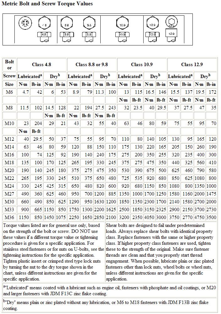
33 Standard Bolt and Screw Torque Values 32
34 This Page Intentionally Left Blank 33

35 REPAIR PARTS General Comments The following includes information regarding parts for the 812A Combine Adapter. Right or left hand parts are determined by sitting in the operator s seat facing forward. The abbreviation A.R. in the USED column indicates As Required. This is because a different number of the specific component may be needed for proper assembly depending on the tolerance of the individual machine. Figure 41. S/N Location Key 1 S/N Tag All parts listed are available through your local dealer. Dealer Contact RCI directly for all part orders for this attachment. Please include a serial number and model of the attachment when placing a parts order. The serial number plate is attached to the main frame of the adapter at the RH side. See Figure 41. Replacement Hardware The use of improper hardware in any location can result in the failure of the component fastened with the hardware or related structures, and can cause personal injury, further damage to the product, or loss of property. Replacement Parts Replacement parts may have occasional differences to the parts being replaced. This difference is typically providing the benefit of a design change made after the release of this publication. 34
36 This Page Intentionally Left Blank 35
37 Repair Parts Index Section Page Drive Assembly 38 Feed Roll Suspension 41 Feed Roll 43 Wide-Body SPFH Components 45 Standard-Body SPFH Components 47 Push Pull Cable 49 Right Side Drive 51 Shields and Bumpers 53 Shipping Stands 55 Right Angle Gearbox RC Vertical Gearbox RC
38 This Page Intentionally Left Blank 37
39 Drive Assembly 38
40 Drive Assembly Key Part No. Description Qty Comments 1 RC Shaft, Hex 1 2 RC Flangette, Bearing 4 3 RC Bearing, Hex 1-1/4 2 4 RC Spacer 1 5 RC Plate, Bearing Adjustment 1 6 RC Flangette 2 7 RC Frame, Adapter 1 8 RC Bearing, Ball 1 10 RC Assembly, Take up 1 11 RC Gearbox, Right Angle 1 12 RC Gearbox, Vertical 1 13 RC Bundle, Quick Attach 1 14 RC Assembly, Skid Shoe 1 15 RC Shaft, Lower Drive 1 16 RC Washer, Hex 1-1/ RC Shaft, Drive 35E 1 18 RC Assembly, Sprocket 1 19 RC Hub, Shear 1 20 RC Sprocket, Bearing 1 21 RC Chain, #80 Roller 1 22 RC Mount, Guard 1 23 RC Cover 1 24 RC Guard 1 25 RC Nut, 1/2-13 gr 9 YZ Top Lock 4 26 RC Bolt, 1/2-13 x 2-3/4 Gr 8 YZ Hex 4 27 RC Bolt, 5/16-18 x 3/4 Gr5 YZ Hex 4 28 RC Washer, Lock, 5/ RC Washer, 5/16 SAE YZ Flat 8 30 RC Nut, 5/16-18 YZ Hex 4 31 RC Ring, Crescent 2 32 RC Washer, M14 Flat 4 33 RC Washer, Lock M RC Nut, 1/2-13 YZ Nylock 4 35 RC Washer, 3/4 SAE YZ Flat RC Nut, 1/2-13 YZ Hex 2 37 RC Bolt, 3/8-16 x 1 CZ Carriage 7 38 RC Bolt, 1/2-13 X 1-1/4 CZ Carriage 4 39 RC Nut, 3/8-16 YZ Nylock 9 Drive Assembly - Continued 39
41 Key Part No. Description Qty Comments 40 RC Washer, 3/8 SAE YZ Hard Flat 7 41 RC Bolt, 3/4-10 x RC Nut, 3/4-10 Gr 5 YZ Nylock 1 43 RC Washer, 1-3/ RC Bolt, M14-2 X 30mm YZ Hex 4 45 RC Washer, 1/2 YZ USS Flat 8 46 RC Bolt, 1/2-13 x 2 Gr 5 YZ Hex 4 47 RC Washer, Lock, 1/ RC Bolt, 1/2-13 x 1-1/4 Gr 5 YZ Hex 4 49 RC Washer, 1/2 SAE YZ Flat 2 50 RC Bolt, 1/2-13 x 1 3/4 Gr 5 YZ Hex 4 51 RC Bolt, 3/8-16 x 2 Gr5 YZ Hex 2 52 RC Washer, 1-3/8 Thin 1 53 RC Bearing 1 54 RC Snap Ring, 1-5/8 Bore Internal 1 55 RC Sprocket, Drive 1 56 RC Bearing, Flanged 1 57 RC Bearing, Sleeve 1 58 RC Nut, 1/4-20 YZ Nylock 1 59 RC Bolt, 1/4-20 x 1-1/2 Gr 5 YZ Hex 1 60 RC Ring, Retaining 1 40
42 Feed Roll Suspension 41
43 Feed Roll Suspension Key Part No. Description Qty Comments 1 RC Assembly, Take Up 2 2 RC Flangette, Bearing 4 3 RC Bearing, 7/8 Hex 2 4 RC Shaft, Hex 1 5 RC Arm, Stabilizer 1 6 RC Strap 4 7 RC Washer, 7/8 Hex 6 8 RC Spring 2 9 RC Weldment, Feed Roll Arm 2 10 RC Assembly, Feed Roll 1 11 RC Washer, 1-1/4 Hex 2 12 RC Arm, Stablizer Lockout 1 13 RC Washer, 5/16 SAE YZ Flat 4 14 RC Ring, Crescent 2 15 RC Bolt, 1/2-13 x 2-1/2 Gr5 YZ Hex 1 16 RC Nut, 1/2-13 YZ Nylock 1 17 RC Nut, 1/2-13 YZ Hex 4 18 RC Nut, 5/16-18 YZ Nylock 4 19 RC Pin, 5/32" x 1-1/4" Roll 2 20 RC Pin, 5/32 x 1 YZ Cotter 6 21 RC Washer, 1/2 SAE YZ Flat 6 22 RC Bolt, 5/16-18 x 1 CZ Carriage 4 23 RC Bolt, 5/8-11 x 3-1/2 YZ Gr8 Hex 2 24 RC Nut, 5/8-11 YZ Nylock 2 25 RC Pin, 1/2 x 1-1/4 Clevis 6 26 RC Bearing, 1-1/4 Hex 2 27 RC Bumper 2 28 RC Screw, 1/4-20 x 5/8 Socket Cap 4 42
44 Feed Roll 43
45 Feed Roll Key Part No. Description Qty Comments 1 RC Assembly, Header Feed Roll 2 2 RC Weldment, Deep Paddle 6 3 RC Shaft, Feed Roll 1 4 RC Bolt, 5/16-18 x 3/4 Gr 5 Serrated Flange 12 5 RC Bolt, 3/8-16 x 2-1/4 Gr 5 YZ Hex 4 6 RC Nut, Nylock 3/ RC Bolt, 3/8-16 x 1 Gr5 Serrated Flange 30 8 RC Nut, Flange, 3/8-16, YZ 30 9 RC Bar, Feeding 6 44
46 Wide-Body SPFH Components 45
47 Wide-Body SPFH Components Key Part No. Description Qty Comments 1 RC Frame, Adapter 1 2 RC Support, Floor 2 3 RC Floor, Throat 1 4 RC Spacer 3 5 RC Seal, Wide Floor 1 6 RC Washer, Lock, 5/ RC Washer, 5/16 SAE YZ Flat 21 8 RC Nut, 5/16-18 YZ Nylock 12 9 RC Bolt, 5/16-18 x 1 Gr5 YZ Hex 6 10 RC Bolt, 5/16-18 x 1-1/4 Gr5 YZ Hex 3 11 RC Bolt, 5/16-18 x 1 CZ Carriage 6 12 RC Screw, 5/16-18 x 1-1/4 CZ Button Socket 3 13 RC Washer, 1/4 YZ Flat 4 14 RC Nut, 1/4-20 YZ Nylock 2 15 RC Bolt, 1/4-20 x 3/4 Hex 2 16 RC Plate, Filler 1 46
48 Standard-Body SPFH Components 47
49 Standard-Body SPFH Components Key Part No. Description Qty Comments 1 RC Nut, 5/16-18 YZ Nylock 12 2 RC Bolt, 5/16-18 x 1 Gr5 YZ Hex 10 3 RC Bolt, 5/16-18 x 1-1/4 Gr5 YZ Hex 3 4 RC Washer, 5/16 SAE YZ Flat 25 5 RC Washer, Lock, 5/ RC Bolt, 5/16-18 x 1 CZ Carriage 6 7 RC Screw, 5/16-18 x 1-1/4 CZ Button Socket Cap 3 8 RC Washer, 1/4 YZ Flat 4 9 RC Nut, 1/4-20 YZ Nylock 2 10 RC Bolt, 1/4-20 x 3/4 Gr 5 YZ Hex 2 11 RC Support, Floor 2 12 RC Floor, Throat 1 13 RC Spacer 6 14 RC Seal, Floor Narrow 1 15 RC Plate, Filler 1 16 RC Block, Merging 2 See Notes* *Part is no longer used and is not needed. 48
50 Push-Pull Cable 49
51 Push Pull Cable Key Part No. Description QTY Comments 1 RC Cable, Push-Pull 1 2 RC Clevis 2 3 RC Assembly, Handle 1 4 RC Spacer 2 5 RC Pin, Locking 1 6 RC Pin, Locking 2 7 RC Bar, Pull 2 8 RC Assembly, Lever 1 9 RC Washer, Lock, 5/ RC Washer, 5/16 SAE YZ Flat 5 11 RC Washer, 5/16 USS Flat 4 12 RC Bolt, 5/16-18 x 2-3/4 Gr5 YZ Hex 2 13 RC Nut, 5/16-18 YZ Nylock 4 14 RC P-Clamp 4 15 RC Bolt, 5/16-18 x 1 Gr5 YZ Hex 6 16 RC Bolt, 5/16-18 x 1-1/4 Gr5 YZ Hex 2 50
52 Right Side Drive 51
53 Ride Side Drive Key Part No. Description Qty Comments 1 RC Weldment, Bearing Bracket 1 2 RC Flangette 4 3 RC Bearing, Ball 2 4 RC Shaft, Drive 1 5 RC Shield, PTO 1 6 RC Shield 1 7 RC Driveshaft, 44E 1 8 RC Hinge, Stainless 1 9 RC Shield, PTO 1 10 RC Latch 1 11 RC Washer, 5/16 YZ Lock 5 12 RC Bolt, 5/16-18 x 3/4 Gr5 YZ Hex 5 13 RC Washer, 3/8 SAE YZ Hard Flat 6 14 RC Washer, 1/2 SAE YZ Flat 4 15 RC Washer, 5/16 SAE YZ Flat 5 16 RC Washer, 1/2 YZ Lock 4 17 RC Bolt, 3/8-16 x 1 CZ Carriage 6 18 RC Nut, 3/8-16 YZ Nylock 6 19 RC Nut, 8-32 YZ Nylock 3 20 RC Machine Screw, 8-32 x 3/4 SI Rd Head 6 21 RC Washer, #8 SAE YZ Flat 9 22 RC Bolt, 1/2-13 x 1-1/4 Gr 5 YZ Hex 4 23 RC Bolt, M14-2 x 25mm YZ Hex 2 24 RC Washer, M14 Lock 2 25 RC Washer, M14 Flat 2 26 RC Frame, Adapter 1 52
54 Shields and Bumpers 53
55 Shields and Bumpers Key Part No. Description Qty Comments 1 RC Frame, Adapter 1 2 RC Shield, PTO 1 3 RC Pad, Wear 2 4 RC Shield, RH Feeder 1 5 RC Shield, LH Feeder 1 6 RC Strip, Wear 3 7 RC Shield, Intake 1 8 RC Shield, Chain 1 9 RC Weldment, Stop Block 2 10 RC Pad, Bumper 2 11 RC Hinge, Stainless 1 12 RC Latch 1 13 RC Bolt, 5/16-18 x 3/4 Gr5 YZ Hex RC Washer, Lock, 5/ RC Washer, 5/16 SAE YZ Flat RC Screw, 8-32 x 3/4 SI Rd Head Machine 6 17 RC Washer, #8 SAE YZ 9 18 RC Nut, 5/16-18 YZ Nylock 4 19 RC Bolt, 3/8-16 x 3/4 Gr 5 YZ Hex 4 20 RC Washer, 3/8 YZ Lock 4 21 RC Nut, 8-32 YZ Nylock 3 22 RC Screw, 5/16-18 x 3/4 CZ Flat Head Socket RC Screw, 5/16-18 x 3/4 CZ Button Socket Cap 7 24 RC Screw, 5/16-18 x 1-1/4 CZ Flat Head Socket 4 25 RC Screw, 1/2-13 x 1-1/4 CZ Flat Head Socket 4 26 RC Nut, 1/4-20 YZ Nylock 4 Spares 27 RC Bolt, 1/4-20 x 1-1/2 Gr5 YZ Hex 4 Spares 54
56 Shipping Stands 55
57 Shipping Stands Key Part No. Description Qty Comments 1 RC Stand, Shipping 1 2 RC Stand, Jack 2 3 RC Tube 2 4 RC Pin, 1/2 x 2-1/2 Bent Pull Hitch 4 Supplied with clip 5 RC Bolt, 3/8-16 x 1 Gr5 Serrated Flange 4 56
58 Right Angle Gearbox - RC
59 Right Angle Gearbox - RC Key Part No. Description Qty Comments 1 RC Casting, Mach 600 Tap 1 2 RC Casting, Mach 600 Thru 1 3 RC Suba, Stub Shaft/Gear 1 4 RC Suba, Cross Shaft/Gear 1 5 RC Bearing, Cone # RC Bearing, Cup # RC Bearing, Cone TK# RC Bearing, Cone TK# RC Bearing, Cup TK# RC Retaining Ring, Ext Shft 1 11 RC Seal, (R) TC 2 12 RC Seal, End Cap, RC Bolt, 3/8-16 x 2.25 SHCS 1 14 RC Plug, 1/2-14 NPT SCHD W/3M 1 15 RC Bushing, 1/2 NPT to 1/8 NPT 1 16 RC Plug, 1/8-27 NPT Vent 5PSI 1 17 RC Lube/EP 80W90 AR 58
60 Vertical Gearbox - RC
61 Vertical Gearbox - RC Key Part No. Description Qty Comments 1 RC Sleeve 2 2 RC Seal, Double Lip 4 50X90X10 3 RC Ring, Snap 4 90 UNI RC Elbow, 90 3/8" Gas 1 5 RC Plug, 3/8" Gas Oil Filler 1 6 RC Bearing RC Wheel, Crown 3 8 RC Pin, Spring 2 A8X50 U RC Key, Parallel 3 B 16X10X30 10 RC Shim 2 11 RC Cap 2 80X10 12 RC Shaft 1 13 RC Ring, Snap 2 80 UNI RC Bearing 2 NJ RC Bolt, M8X RC Casing 1 17 RC Casing 1 18 RC Nut, M8 Hex RC Plug, 3/8" Gas 2 20 RC Shim
62 This Page Intentionally Left Blank 61
63 Pre-delivery Checklist (Return this copy to RCI) After the unit has been assembled and lubricated and prior to delivery to customer, the adapter needs to be inspected thoroughly to ensure it is in proper working order. The following checklist must be reviewed and each item found to be satisfactorily completed. Adapter has been setup according to the instructions included in this manual. All grease fittings have been lubricated. All guards, shields and safety decals are in place, securely fastened, and operate correctly. All nuts and bolts have been tightened and inspected. Adjustments have been made as described in the Adjustments section of this manual Plastic insert centered on adapter at feed roll housing area, undamaged, and in working order. All moving parts operate freely. Spare shear bolts in place. Feed roll locked in the raised position and spring tension set properly. All applicable warranty information recorded. I acknowledge that the pre-delivery service was performed and the unit is ready for delivery to the customer. Dealership s Name Representative Date Model Number Serial Number Date Sold Owner s Name and Address Name Address City, State, Zip Original: Enclose in manual and give to customer at time of delivery. Copy: Dealership Copy: RCI Engineering LLC Fax: info@rciengineering.com Mail: 208 River Knoll Drive, Mayville, WI
64 This Page Intentionally Left Blank 63
65 Delivery Checklist (Copy for Return to RCI) The following items must be performed when delivering the attachment to the customer. Check off each item as it is performed. Provide the customer with the Operator's Manual and instruct them to read prior to operating the unit. Review and explain all safety information and operating adjustments. Review and explain maintenance and lubrication schedule that is required to ensure proper operation and long life. Show how to properly adjust the spring tension as instructed in the Adjustments section. Make it be known that if the customer can visit or call the dealership to discuss any questions or problems they may encounter. Complete the Owner s Registration with the customer, ensure it is completely filled out, and return it to RCI Engineering. Date Delivered Signature Original: Enclose in manual and give to customer at time of delivery. Copy: Dealership Copy: RCI Engineering LLC RCI Engineering LLC Fax: info@rciengineering.com Mail: 208 River Knoll Drive, Mayville, WI
66 This Page Intentionally Left Blank 65
67 Feedback for RCI Use this page to provide feedback to RCI regarding this product, manual, or other ways for RCI to improve in the future. Product: Recutter Screen Bundle for 8000-Series SPFH Dealership Name: Dealership City: Dealership Phone: Technician: S/N: Date: Installation Time (hours): Comments: Send to RCI Engineering: RCI Engineering LLC Fax: Mail: 208 River Knoll Drive, Mayville, WI
68 208 River Knoll Drive Mayville, WI Fax
Operator Manual. Includes operating, adjustment, maintenance, technical, repair parts, and safety instructions for the 8A Bumper Attachment.
 8A BUMPER ATTACHMENT Operator Manual Includes operating, adjustment, maintenance, technical, repair parts, and safety instructions for the 8A Bumper Attachment. Please retain this document for future reference.
96A Windrow Pickup Attachment For John Deere Model 3975 Pull-Type Forage Harvester. Operator's Manual
 96A Windrow Pickup Attachment For John Deere Model 3975 Pull-Type Forage Harvester Operator's Manual Includes installation, operating, adjustment, maintenance, technical, repair parts and safety instructions
Draper Platform Adaptation Bundle
 Draper Platform Adaptation Bundle 7050-Series Self-Propelled Forage Harvester 900D-Series Draper Platform RC042050 Operator s Manual Includes installation, operating, adjustment, technical, repair parts
186M Windrow Merger. Operator Manual
 186M Windrow Merger Operator Manual Includes operating, adjustment, maintenance, technical, repair parts and safety instructions for the 186M Windrow Merger. Please retain this document for future reference.
8A Bumper Attachment 17 October Series and 8000-Series SPFH
 8A Bumper Attachment 17 October 2017 7000-Series and 8000-Series SPFH The 8A Bumper Attachment is available from RCI Engineering for the John Deere 7000- and 8000-Series Self-Propelled Forage Harvesters.
TABLE OF CONTENTS. Warranty Disclaimers Delivery Checklist After Sale Checklist Safety Set Up... 8
 TABLE OF CONTENTS Pickett Equipment Warranty... 2 Warranty Disclaimers... 3 Delivery Checklist... 4 After Sale Checklist... 4 Safety... 5-7 Set Up... 8 Machine Adjustments and Operation... 9 Maintenance
ROTARY TILLER. Operation, Service & Parts Manual For "AS" Series. FORM: ASTillerBook.QXD
 ROTARY TILLER Operation, Service & Parts Manual For "AS" Series FORM: ASTillerBook.QXD April 2002 TABLE OF CONTENTS Preparation......................................1 Assembly Instructions.............................2
AGCO. Corn Header Manual d HEADSIGHT.COM
 AGCO Corn Header Manual 09020401d HEADSIGHT.COM 574.546.5022 About Headsight Headsight Contact Info Headsight, Inc. 4845 3B Road Bremen, IN 46506 Phone: 574-546-5022 Fax: 574-546-5760 Email: info@headsight.com
Wheel Horse. 36 Tiller. Model No & Up. Operator s Manual
 FORM NO. 8 9 Rev. A Wheel Horse 6 Tiller for Classic Garden Tractors Model No. 7970 690000 & Up Operator s Manual IMPORTANT: Read this manual carefully. It contains information about your safety and the
5000 SERIES STALK DEVASTATOR CORN STALK ROLLER
 5000 SERIES STALK DEVASTATOR CORN STALK ROLLER *PATENTED* 5000-025A, 5000-026A, 5000-027A, 5000-028A, 5000-034A John Deere Model Corn Heads (606C, 643, 693, 706C, 608C, 843, 893, 708C, 612C, 612FC Folding,
GERINGHOFF. Corn Header Manual f HEADSIGHT.COM
 GERINGHOFF Corn Header Manual 09020701f HEADSIGHT.COM 574.546.5022 About Headsight Headsight Contact Info Headsight, Inc. 4845 3B Road Bremen, IN 46506 Phone: 574-546-5022 Fax: 574-546-5760 Email: info@headsight.com
RED23305 Owner s Manual
 RED23305 Owner s Manual 5 foot, 3-Point Mounted Snow Blower 270 West Park Avenue Huron, SD 57350 866-526-5682 Serial Number: Date of Purchase: Red Devil Snow Blower See Figure 1. 1. The Red Devil Snow
03-SERIES 4 & 6-ROW RIGID & FOLDING PEANUT VINE CONDITIONER OPERATOR S MANUAL THIS MANUAL TO ACCOMPANY MACHINE
 03-SERIES 4 & 6-ROW RIGID & FOLDING PEANUT VINE CONDITIONER OPERATOR S MANUAL THIS MANUAL TO ACCOMPANY MACHINE PART NO. 03-OM-03 Printing Date: SEPT 2012 WARRANTY POLICY KELLEY MANUFACTURING COMPANY (KMC)
OPERATOR S MANUAL. 20-bu 3-Point Hitch Material Collection System. LP65048 Supplier ST /07/2017 English. North American Edition Printed in USA
 OPERATOR S MANUAL 20-bu 3-Point Hitch Material Collection System LP65048 Supplier ST48289 11/07/2017 English North American Edition Printed in USA Introduction Using Your Operator s Manual Read this entire
TABLE OF CONTENTS DESCRIPTION. Safety Instructions & Safety Sign Locations Operating Instructions Assembly Instructions...
 TABLE OF CONTENTS DESCRIPTION PAGE Warranty... 1 Safety Instructions & Safety Sign Locations... 2 Operating Instructions... 3 Assembly Instructions... 5 500 & 600 Snowblower Drawings... 8 500 & 600 Snowblower
320 Series Models 325, 326, 327
 0 Series Models,, ROTARY MOWER Published 0/ PARTS MANUAL SECTION An Operator s Manual was shipped with the equipment. The Operator s Manual is an integral part of the safe operation of this machine and
CAUTION CAUTION indicates a potentially hazardous situation which, if not avoided, may result in minor or moderate injury.
 Instruction Manual Notes: Page Manual Conventions This manual uses the following symbols to help differentiate between different kinds of information. The safety symbol is used with a key word to alert
OPERATOR S MANUAL FABRIC 3-BAG GRASS CATCHER PART NO PRINTED 8/2012 PRINTED IN USA
 OPERATOR S MANUAL FABRIC -BAG GRASS CATCHER Models: GC-STC-V This manual contains the operating instructions and safety information for your Scag mower accessory. Reading this manual can provide you with
WARRANTY REGISTRATION AND POLICY
 WARRANTY REGISTRATION AND POLICY Buhler Manufacturing products are warranted for a period of twelve (12) months from original date of purchase, by original purchaser, to be free from defects in material
OPERATOR S MANUAL MODEL GC-STC-V
 MODEL GC-STC-V THIS MANUAL CONTAINS THE OPERATING INSTRUCTIONS AND SAFETY INFORMA- TION FOR YOUR SCAG ACCESSORY. READ- ING THIS MANUAL WILL PROVIDE YOU WITH MAINTENANCE AND ADJUSTMENT PROCEDURES TO KEEP
Operation and Parts Manual
 Operation and Parts Manual 3-Point PTO and Hydraulic Stump Grinders Models: SC-25 and SC-25H SC-50 and SC-50H Safety Operation Maintenance Repair Troubleshooting Parts Parts SC-50 and SC-50-H Stumpbuster
Instruction Manual. ATV Plow Tube System
 Instruction Manual ATV Plow Tube System Manual Conventions This manual uses the following symbols to help differentiate between different kinds of information. The safety symbol is used with a key word
250P Manure Spreader
 0P Manure Spreader Illustrated Parts Breakdown Page - Page Page Page Page Page Page Page Page Page Page Page Page Page Page - Page Page Page 0 Complete Front End PTO/Jack/Hitch Assembly Front Pulley Assembly
CORN HEADER MANUAL: CNH PRE-2012
 CORN HEADER MANUAL: CNH PRE-2012 09020201c HEADSIGHT.COM 574.546.5022 About Headsight Headsight Contact Info Headsight, Inc. 4845 3B Road Bremen, IN 46506 Phone: 574-546-5022 Fax: 574-546-5760 Email:
Mulcher Operators Manual
 Mulcher Operators Manual Skid Pro Attachments PO Box 982 Alexandria, MN 56308 October 2015 1 2 Contents 1. Introduction And Warranty... 4 1.1 Introduction... 4 1.2 Warranty... 4 2. Component Identification...
DRAGO. Corn Header Manual f HEADSIGHT.COM
 DRAGO Corn Header Manual 09020801f HEADSIGHT.COM 574.546.5022 About Headsight Headsight Contact Info Headsight, Inc. 4845 3B Road Bremen, IN 46506 Phone: 574-546-5022 Fax: 574-546-5760 Email: info@headsight.com
GROUNDSMASTER. 52 Recycler. for 120 Traction Unit. Model No & UP. Operator s Manual
 FORM NO. 8-980 Rev A GROUNDSMASTER 5 Recycler for 0 Traction Unit Model No. 077 79000 & UP Operator s Manual IMPORTANT: Read this manual carefully. It contains information about your safety and the safety
ROTARY TILLER. Operation, Service & Parts Manual For P-P/C Series. November 1996 (Rev. 4-05) FORM: PTillerBook.QXD
 FORM: PTillerBook.QXD") ROTARY TILLER Operation, Service & Parts Manual For P-P/C Series FORM: PTillerBook.QXD November 1996 (Rev. 4-05) TABLE OF CONTENTS Preparation......................................1 Assembly Instructions.............................2
ROTARY TILLER Operation, Service & Parts Manual For P-P/C Series FORM: PTillerBook.QXD November 1996 (Rev. 4-05) TABLE OF CONTENTS Preparation......................................1 Assembly Instructions.............................2
POST HOLE DIGGER. Operation, Service & Parts Manual For Models D20 & D40. FORM: D20_40DigRev.QXD
 POST HOLE DIGGER Operation, Service & Parts Manual For Models D20 & D40 FORM: D20_40DigRev.QXD September 2006 Revised August 2009 TABLE OF CONTENTS Introduction.............................1 Preparation..............................2
Operator Manual. Windrow Merger Attachment For John Deere R450 Self-Propelled Windrower
 Windrow Merger Attachment For John Deere R450 Self-Propelled Windrower Operator Manual Includes installation, operating, adjustment, maintenance, technical, repair parts and safety instructions for the
Operator's Manual. VC-60 & VC-60 Plus Harper Industries, Inc. 7/03 Part No
 Operator's Manual VC-60 & VC-60 Plus 2003 Harper Industries, Inc. 7/03 Part No. 970066 Thank you for purchasing a Harper/Goossen Verti-Cutter. As with all Harper/Goossen products, the Harper/Goossen Verti-Cutter
OPERATOR S MANUAL MODEL GC-SFZ
 R Made in the USA by MODEL GC-SFZ THIS MANUAL CONTAINS THE OPERATING INSTRUCTIONS AND SAFETY INFORMA- TION FOR YOUR SCAG ACCESSORY. READ- ING THIS MANUAL WILL PROVIDE YOU WITH MAINTENANCE AND ADJUSTMENT
OPERATOR and PARTS MANUAL GRAIN GRINDER MODEL GG 7
 1 Serial # GG7-AUG10-71-1013 and Higher 2014 and up ROTO GRIND OPERATOR and PARTS MANUAL GRAIN GRINDER MODEL GG 7 ROTO GRIND BURROWS ENTERPRISES LLC 2024 East 8 th Street Greeley, Colorado 80631 970-353-3769
ATV TRACK KIT. Operator s Manual Installation Instructions Service Instructions Replacement Parts List. Effective Date: October, 2012
 p/n 2258-642 ATV TRACK KIT Operator s Manual Installation Instructions Service Instructions Replacement Parts List Track Assembly Kits (p/n 1436-204) Mounting Assembly Kits (p/n 1436-205) 1436-815) Effective
AGCO Conversion Manual a HEADSIGHT.COM
 AGCO 3300 Conversion Manual 09040404a HEADSIGHT.COM 574.546.5022 About Headsight Headsight Contact Info Headsight, Inc. 4845 3B Road Bremen, IN 46506 Phone: 574-546-5022 Fax: 574-546-5760 Email: info@headsight.com
OPERATOR and PARTS MANUAL GRAIN GRINDER MODEL GG 10
 1 Serial # GG10-AUG10-6-0701 to GG10-AUG10-276-0314 ROTO GRIND OPERATOR and PARTS MANUAL GRAIN GRINDER MODEL GG 10 ROTO GRIND BURROWS ENTERPRISES, INC. 2024 East 8 th Street Greeley, Colorado 80631 970-353-3769
AG PRO SS Owner s Manual & Parts Book
 AG PRO SS Owner s Manual & Parts Book Purchase Date Serial Number Model Number Tractor Model Dealer PN: 63-19460 SN: 10204276-... Date 1-10-2017 Description Contents Page To The Owner, Maintenance, Safety
INSTALLATION INSTRUCTIONS
 INSTALLATION INSTRUCTIONS WARNING: NEVER EXCEED YOUR VEHICLE MANUFACTURER'S RECOMMENDED TOWING CAPACITY A20 5TH WHEEL HITCH TABLE OF CONTENTS Page# Description 1 Warnings & Precautions 2 - Assembly & Installation
Installation / Owners Manual
 DEALER/INSTALLER: (1) Provide this Manual to end user END USER: Part Number: 94621 94622* *Packaged for Individual sale. (1) Read and follow this Manual for Reese Installation. (2) Save this Manual for
ROTARY MOWER OPERATION, SERVICE & PARTS MANUAL FOR
 ROTARY MOWER OPERATION, SERVICE & PARTS MANUAL FOR L-G-40-40-P, L-G-48-40-P, L-G-60-40-P & L-G-72-40-P Slip Clutch Models: L-G-60-40-SC-P & L-G-72-40-SC-P February 2003 FORM: RotMwrBook.QXD TABLE OF CONTENTS
WARRANTY REGISTRATION AND POLICY
 WARRANTY REGISTRATION AND POLICY Buhler Manufacturing products are warranted for a period of twelve (12) months from original date of purchase, by original purchaser, to be free from defects in material
CRUSTBUSTER OWNER / OPERATOR MANUAL
 CRUSTBUSTER OWNER / OPERATOR MANUAL MODEL # CB-1 CRUSTBUSTER Manufactured by: LEWIS BROTHERS MANUFACTURING, INC. Post Office Box 146 Baxley, GA 31513 Tel: (912) 367-4651 Fax: (912) 367-3958 5-2-17 1 INTRODUCTION
Technical Support Line: (952) Hanover Ave. Lakeville, MN
 Hanover Ave. Lakeville, MN") Technical Support Line: (952) 985-5675 Email: Sales@QA1.net 21730 Hanover Ave. Lakeville, MN 55044 www.qa1.net INSTALLATION INSTRUCTIONS QA1 1967-1979 Mopar A-Body Rear 6 link Conversion System QA1 p/n
Technical Support Line: (952) 985-5675 Email: Sales@QA1.net 21730 Hanover Ave. Lakeville, MN 55044 www.qa1.net INSTALLATION INSTRUCTIONS QA1 1967-1979 Mopar A-Body Rear 6 link Conversion System QA1 p/n
BUSH HOG LAND MAINTENANCE REPAIR PARTS MANUAL MODEL: 3414 SECTION: 67
 BUSH HOG LAND MAINTENANCE REPAIR S MANUAL MODEL: SECTION: 0 Griffin Ave. Selma, AL 0 () - () -00 Parts Ordering -00-0- Fax -00-- www.bushhog.com BUSH HOG/ LAND MAINTENANCE REPAIR S MANUAL July, 0 ROTARY
Sync-Row for MONOSEM Twin-Row. Setting the Twin-Row Stagger INSURE THESE VALUES ARE CORRECT FOR YOUR TWIN ROW PLANTER
 Sync-Row for MONOSEM Twin-Row TIMING CHART 30" ROW SPACING Chart for Adjustable Metering Sprocket INSURE THESE VALUES ARE CORRECT FOR YOUR TWIN ROW PLANTER Crop Corn Number of Seed Disk Cells (holes) 18
36 Tiller Wheel Horse Lawn and Garden Tractor Attachment
 Form No. 9 6 Rev B 6 Tiller Wheel Horse Lawn and Garden Tractor Attachment Model No. 797 890000 and Up Operator s Manual English(En) Contents Page Introduction................................ Safety.....................................
PARTS MANUAL SECTION. Models 295, 296, 297, 1297 ROTARY MOWER
 0 Series Models,,, ROTARY MOWER Published 0/ PARTS MANUAL SECTION An Operator s Manual was shipped with the equipment. The Operator s Manual is an integral part of the safe operation of this machine and
OPERATOR S MANUAL REPAIR PARTS CATALOG. Models: SCP-51 & SCP-71 SCP-52 & SCP-72 SCP-91 & SCP-111 SCP-92 & SCP-112 BRILLION FARM EQUIPMENT
 OPERATOR S MANUAL REPAIR PARTS CATALOG Subsoil Chisel Plow Models: SCP-51 & SCP-71 SCP-52 & SCP-72 SCP-91 & SCP-111 SCP-92 & SCP-112 IMPORTANT! Repairs cannot be purchased retail direct from factory. Order
Mulching and Finishing Mowers MP and FP
 Mulching and Finishing Mowers MP and FP Parts Manual Locke Turf 0 Highway E, Opp, Alabama, () -00 Transport Wheel, Tire & Spindle MP and FP ALPHABETICAL INDEX CONTENTS PAGE 00 Hydraulic Cylinder (Rear)
08/2010 Rev. 4/28/2017 FMDL, MANUAL. FMDL-Series Single & Double Eagle Beak Fork-Mounted Drum Lifters Use and Maintenance Manual
 Vestil Manufacturing Corp. 2999 North Wayne Street, P.O. Box 507, Angola, IN 46703 Telephone: (260) 665-7586 -or- Toll Free (800) 348-0868 Fax: (260) 665-1339 www.vestilmfg.com Email: info@vestil.com FMDL-Series
ProLine. 44 Mower. for 120 Traction Unit. Model No & Up. Operator s Manual
 FORM NO. 9 ProLine Mower for 0 Traction Unit Model No. 05 99000 & Up Operator s Manual IMPORTANT: Read this manual carefully. It contains information about your safety and the safety of others. Also become
FLAIL MOWER SHREDDER
 FLAIL MOWER SHREDDER Operation, Service, & Parts Manual For Models: GML41, 49, 61, 69, & 79 February 2006 FORM: GMLMower.QXD TABLE OF CONTENTS Installation....................................................1
HR24TS Rotary Rake. Serial Numbers and higher. Illustrated Parts Breakdown. Guards and Guard Arm, Front Hay Curtain Mount.
 HRTS Rotary Rake Serial Numbers 00 and higher Illustrated Parts Breakdown Page Page Page Page Page Page Page Page Page Page 0 Page Page Page Page Page Page Page Page Page Page 0 Tongue Front Frame Guards
Planting Components. Operator s/parts Manual
 Operator s/parts Manual Unit Mount Conservation Coulter and Spring Package Attachment for JD 7000, JD 7200, White 6100, Kinze Planters and Great Plains Row Units Planting Components! Read the operator
TO THE OWNER. Model : Product Serial Number : WARNING
 28174 (09/2/11) TO THE OWNER This manual contains information concerning the adjustment, assembly and maintenance of your Tube-Line Accelerator. You have purchased a dependable machine, but only by proper
Twin Screw Undercar Conveyor
 Twin Screw Undercar Conveyor Owner s Manual #19015700 05-00 Table of Contents Operator Qualifications...................................... 1 Safety.................................................. 2-4
BUSH HOG LAND MAINTENANCE REPAIR PARTS MANUAL MODEL: TD-1100 SECTION: 66
 BUSH HOG LAND MAINTENANCE REPAIR S MANUAL MODEL: TD-00 SECTION: 0 Griffin Ave. Selma, AL 0 () - () -00 Parts Ordering -00-0- Fax -00-- www.bushhog.com BUSH HOG/ LAND MAINTENANCE REPAIR S MANUAL JUNE, 00
LIMITED WARRANTY DISCLAIMER OF IMPLIED WARRANTIES & CONSEQUENTIAL DAMAGES
 Published 08/15 LIMITED WARRANTY Bush Hog warrants to the original purchaser of any new Bush Hog equipment, purchased from an authorized Bush Hog dealer, that the equipment be free from defects in material
BALE KING GT40 Grain Feeder Operator's & Parts Manual Last Update: November 20, 2014 Bridgeview Manufacturing Inc - 1 -
 BALE KING GT40 Grain Feeder Operator's & Parts Manual Last Update: November 20, 2014 Bridgeview Manufacturing Inc - 1 - Your Authorized Dealer: Your Serial Number: The Serial Number is located on the tank.
HT46X Rotary Tedder. Illustrated Parts Breakdown. Center Section
 HTX Rotary Tedder Illustrated Parts Breakdown Page Page Page Page Page Page Page Page Page Page 0 Page Center Section Hydraulics Outer Wing Assembly Center Bolted Components Tine Rotor and Hardware Tilt
OWNER S GUIDE 8A DURALIFT II 13,200 LB. CAPACITY. Link Mfg. Ltd th St. N.E. Sioux Center, IA USA
 OWNER S GUIDE 8A000715 DURALIFT II 13,200 LB. CAPACITY Link Mfg. Ltd. 223 15th St. N.E. Sioux Center, IA USA 51250-2120 www.linkmfg.com QUESTIONS? CALL CUSTOMER SERVICE 1-800-222-6283 DEALER / INSTALLER:
BH200 SERIES ROTARY CUTTER
 Revised Published01/19 BH200 SERIES ROTARY CUTTER PARTS MANUAL SECTION 121 MODELS BH215, BH216, BH217 An Operator s Manual was shipped with the equipment. The Operator s Manual is an integral part of the
5000 SERIES STALK DEVASTATOR CORN STALK ROLLER
 5000 SERIES STALK DEVASTATOR CORN STALK ROLLER *PATENTED* 5000-026A 8 ROW JD (608C, 843, 893) OWNER S MANUAL PART IDENTIFICATION 2565-794_RevC 08/2017 YETTER MANUFACTURING CO. Founded 1930 Colchester,
Operating Instructions and Parts Manual AHR-50 Auto Rewind Hose Reel
 Operating Instructions and Parts Manual AHR-50 Auto Rewind Hose Reel JET 427 New Sanford Road LaVergne, Tennessee 37086 Part No. M-426238 Ph.: 800-274-6848 Revision C 04/2017 www.jettools.com Copyright
2720/12720 PARTS MANUAL 72A SECTION FLEX WING ROTARY MOWER
 0/0 This Manual applies to models 0 and 0 that use a blade pan which measures. blade hole center to blade hole center. Also blades measure 8. from hole center to blade tip. See Section if these dimensions
BUSH HOG LAND MAINTENANCE REPAIR PARTS MANUAL MODELS: RPM & RPM SECTION: 79
 BUSH HOG LAND MAINTENANCE REPAIR S MANUAL MODELS: -0 RPM & -000 RPM SECTION: 9 0 Griffin Ave. Selma, Al. 0 () - () -00 Parts Ordering -00-0- Fax -00-- www.bushhog.com April, 0 BUSH HOG/ LAND MAINTENANCE
450 & Slant Top Owner s Manual & Parts Book
 0 & 0 - Slant Top Owner s Manual & Parts Book Purchase Date Serial Number Model Number Tractor Model PN: - Dealer Date -- Contents Description Page To The Owner & Maintenance Safety Precautions & Torque
B-DM-6 Diamond Master Operation & Parts Manual Model no.: B-DM-6
 B-DM-6 Diamond Master Operation & Parts Manual Model no.: B-DM-6 TABLE OF CONTENTS 01 Cover Page 02 Table of Contents 03 Warranty 04 Diamond Master Information & Basic Maintenance 05 Adjustment of Tools
OPERATIONS MANUAL & PARTS LIST. MODEL: 600cm 6 CU. FT. 1 of 16
 OPERATIONS MANUAL & PARTS LIST MODEL: 600cm 6 CU. FT. WS500 2-2012/Rev.A 104 S. 8th Ave. Marshalltown, IA Phone 800-888-0127 / 641-753-0127 Fax 800-477-6341 / 641-753-6341 www.marshalltown.com 1 of 16
MK AUGERS POWER SWING KIT ASSEMBLY & OPERATION MANUAL
 MK AUGERS POWER SWING KIT ASSEMBLY & OPERATION MANUAL Read this manual before using product. Failure to follow instructions and safety precautions can result in serious injury, death, or property damage.
Installation Instructions
 Equipment Required: Fastener Kit: F Wrenches: 3/4, 15/16 Drill Bits: 1/4 Other Tools: Drill Short & Long Bed All Megacabs 9464/9474 HIDE-A-GOOSE HITCH INSTALLATION WARNING: Under no circumstances do we
LEWIS WINDROWER OWNER / OPERATOR MANUAL
 LEWIS WINDROWER OWNER / OPERATOR MANUAL MODEL # WR-1 WINDROWER Manufactured by: LEWIS BROTHERS MANUFACTURING, INC. Post Office Box 146 Baxley, GA 31513 Tel: (912) 367-4651 Fax: (912) 367-3958 2-21-14 1
SHEYENNE TELE-BOOM OWNERS MANUAL OPERATOR INSTRUCTIONS PARTS BOOK
 SHEYENNE TELE-BOOM OWNERS MANUAL OPERATOR INSTRUCTIONS PARTS BOOK 701 Lenham Ave. SW PO Box 647 Cooperstown ND 58425 1-800-797-1883 701-797-2700 * 701-797-2584 Fax www.sheyennemfg.com TABLE OF CONTENTS
PM25 & PM35 GRINDER MIXER ILLUSTRATED PARTS LIST
 PM25 & PM35 GRINDER MIXER ILLUSTRATED PARTS LIST Art s-way Manufacturing Co., Inc. 485140 1100 TO THE OWNER Congratulations on the purchase of your new Art s-way grinder mixer. You have selected a top
PARTS MANUAL THIS PAGE INTENTIONALLY LEFT BLANK. Ag-Bag International, Ltd. G7000 June Appendix A
 The parts manual is organized into groups, it is designed to make the locating of parts easier. The exploded drawings also show assembly paths. All parts listed are available from your authorized Ag-Bag
MODEL L/R/EF Sectional Tire Spreader
 MODEL L/R/EF Sectional Tire Spreader Installation, Operation & Repair Parts Information Branick Industries, Inc. 4245 Main Avenue P.O. Box 1937 Fargo, North Dakota 58103 REV08032016 P/N: 81-0195E TABLE
Fast Lift Service Jack, Low Profile
 Blackhawk Automotive is a Licensed Trade Mark Made by SFA Companies, Kansas City, MO Fast Lift Service Jack, Low Profile Operating Instructions & Parts Manual Model BH6023B Capacity 2 Ton! U.S. Patent
4200 & 6200 Owner s Manual & Parts Book
 00 & 00 Owner s Manual & Parts Book Purchase Date Serial Number Model Number Tractor Model PN: - Dealer Date --0 Description Page To The Owner & Maintenance Safety Precautions & Torque Specifications Skid
LORENZ SNOW BLOWER 310 SERIES
 Owner s and Parts Manual LORENZ SNOW BLOWER 30 SERIES (530, 630, 730) LORENZ MFG. CO. 5 30 TH AVENUE SE BENSON MN 565 --3-30 lorenzmfg.com May 00 Contents Page Introduction Safety Specifications Unpacking
MODELS EWR820, EWR1023, EWR1227 PULL TYPE HAY RAKES PARTS MANUAL SECTION 19
 EWR MODELS EWR820, EWR1023, EWR1227 PULL TYPE HAY RAKES Published 04/11 PARTS MANUAL SECTION 19 MATERIAL HANDLING PARTS MANUAL PARTS ORDERING GUIDE The following instructions are offered to help eliminate
Case STX/NH TJ
 Case STX/NH TJ 0-0 Tractors MANUAL Case STX/NH TJ 0-0 Tractors Blades, pivot frames Tractor fit-up Dlock, mounting Hydraulics Operation, maintenance Safety, warranty Industrial Drive, Box 0 Regina, Sask.
Installation Instructions
 Equipment Required: Fastener Kit: F Wrenches: 3/4, 15/16, 10mm, 18mm Drill Bits: 1/4 Other Tools: Drill, Reciprocating saw 9465/9475 HIDE-A-GOOSE HITCH INSTALLATION All Fasteners Typical, Both Sides WARNING:
TT4100 Rotary Tedder
 TT0 Rotary Tedder Serial numbers 0 and higher Illustrated Parts Breakdown Page Page Tongue Assembly S/N - Tongue Assembly S/N to Page Page Page Page Page Tongue Assembly S/N to Tongue Assembly S/N + Main
TO THE OWNER WARNING WARNING
 30608 (18/02/15) TO THE OWNER This manual contains information concerning the adjustment, assembly and maintenance of your Tube-Line Chainless Bale Feeder. You have purchased a dependable machine, but
VR482 Hay Rake OPERATOR & PARTS MANUAL. Last Updated: May 12, 2014
 VR482 Hay Rake OPERATOR & PARTS MANUAL Last Updated: May 12, 2014 Bridgeview Manufacturing Inc. P.O. Box 4 Gerald, SK S0A 1B0 (306) 745-2711 www.bridgeviewmanufacturing.com bmi@sasktel.net Your Authorized
4-Ton Electric Log Splitter
 4-Ton Electric Log Splitter Questions: Support@Powrkraft.com PK65556 2 18ga. @ 20ft, 16ga. @ 50ft, 14 ga. @ 75ft. 12ga @ 100ft, 10ga @ 200ft These are minimum cord requirements. 13-16 Model Number 65556
Commercial Pro Plow Combo, 50" ATV
 CHANGING YOUR LANDSCAPE SINCE 1945 swisherinc.com OWNER S MANUAL 19975 Starting Serial #: L215-001001 Commercial Pro Plow Combo, 50" ATV IMPORTANT Read and follow all Safety Precautions and Instructions
TT6101 Rotary Tedder
 TT0 Rotary Tedder 0/0/0 Illustrated Parts Breakdown Page Chassis Assembly Page Page Transport Axle Assembly S/N - Transport Axle Assembly S/N + Page Page Page Page Page Transport Lock Assembly Lift Frame
LAND MAINTENANCE REPAIR PARTS MANUAL BUSH HOG MODEL: 307 SECTION: 16
 BUSH HOG LAND MAINTENANCE REPAIR S MANUAL MODEL: 0 SECTION: P.O. Box 0 Selma, AL 0-0 () - () -00 Parts Ordering -00-0- Fax -00-- www.bushhog.com BUSH HOG / LAND MAINTENANCE REPAIR S MANUAL SEPTEMBER, 0
Pick Up Broom OWNERS/OPERATORS MANUAL. Model Number. Serial Number. Date of Manufacture. To Serial # Phone:
 Pick Up Broom OWNERS/OPERATORS MANUAL Model Number. Serial Number. Date of Manufacture. To Serial #039 Phone: 77-37-6 //0 Warranty Skid Pro products are warranted to be free from defects, in workmanship,
OPE R AT O R S MANU A L QUICK-HITCH ADAPTER. 5BP (Field conversion kit)
") OPE R AT O R S MANU A L 5BP006750 (Field conversion kit) Manual 5BP97378B Date 06/8/05 SAFETY Take note! This safety alert symbol found throughout this manual is used to call your attention to instructions
OPE R AT O R S MANU A L 5BP006750 (Field conversion kit) Manual 5BP97378B Date 06/8/05 SAFETY Take note! This safety alert symbol found throughout this manual is used to call your attention to instructions
MODEL 5500 Tire Repair Station
 MODEL 5500 Tire Repair Station Installation, Operation and Repair Parts Information Branick Industries, Inc. 4245 Main Ave P.O. Box 1937 Fargo, North Dakota 58103 P/N: 81-0047C TABLE OF CONTENTS SAFETY
BUSH HOG LAND MAINTENANCE REPAIR PARTS MANUAL MODEL: 405 / 406 SECTION: 17
 BUSH HOG LAND MAINTENANCE REPAIR S MANUAL MODEL: 0 / 0 SECTION: 0 Griffin Ave. Selma, AL 0 () - () -00 Parts Ordering -00-0- Fax -00-- www.bushhog.com BUSH HOG/ LAND MAINTENANCE REPAIR S MANUAL SEPTEMBER,
PARTS MANUAL 3510, 3510-O, SECTION ROTARY MOWER
 , -O, ROTARY MOWER Published 0/ S MANUAL SECTION An Operator s Manual was shipped with the equipment. The Operator s Manual is an integral part of the safe operation of this machine and must be maintained
BEFCO. Operator s Manual BABY HOP & HOP FERTILIZER SPREADERS ACCESSORIES SIDE ROW DISCHARGE. AA4-120 (fits models Hop 209 & 212) DEFLECTOR
 DEFLECTOR") BEFCO Operator s Manual BABY HOP & HOP FERTILIZER SPREADERS ACCESSORIES SIDE ROW DISCHARGE AA-0 (fits models Hop 09 & ) DEFLECTOR AA-0 (fits models Baby Hop 0 & 06) 009-95 (fits models Hop 0 & 06) 009-968
BEFCO Operator s Manual BABY HOP & HOP FERTILIZER SPREADERS ACCESSORIES SIDE ROW DISCHARGE AA-0 (fits models Hop 09 & ) DEFLECTOR AA-0 (fits models Baby Hop 0 & 06) 009-95 (fits models Hop 0 & 06) 009-968
Wheel Horse. 44 Snowthrower. for 5xi Lawn and Garden Tractors. Model No & Up. Operator s Manual
 FORM NO. 8 Rev A Wheel Horse Snowthrower for 5xi Lawn and Garden Tractors Model No. 7966 890050 & Up Operator s Manual IMPORTANT: Read this manual, and your tractor manual, carefully. They contain information
INSTALLATION INSTRUCTIONS AND OWNER S MANUAL
 INSTALLATION INSTRUCTIONS AND OWNER S MANUAL Thank you for purchasing the AlloyCover from WeatherTech. Manufactured with pride using superior quality materials and workmanship. With proper care, your cover
Hydraulic Wheel Dolly
 Hydraulic Wheel Dolly Operating Instructions & Parts Manual Model Number HW93765 Capacity 3/4 Ton Made in the U.S.A. This is the safety alert symbol. It is used to alert you to potential personal injury
FORAGE BOX MODEL 5300 REAR UNLOAD OPERATOR'S MANUAL DO NOT OPERATE THIS EQUIPMENT UNTIL THIS MANUAL HAS BEEN READ AND UNDERSTOOD.
 FORAGE BOX MODEL 5300 REAR UNLOAD OPERATOR'S MANUAL DO NOT OPERATE THIS EQUIPMENT UNTIL THIS MANUAL HAS BEEN READ AND UNDERSTOOD. Miller-St. Nazianz, Inc. Art s-way Manufacturing Co., Inc. P.O. Box 127