The Potsdam Red Sandstone Company s Water Wheel
|
|
|
- Chester Hoover
- 6 years ago
- Views:
Transcription
1 The Potsdam Red Sandstone Company s Water Wheel In Scientific American, Vol. LXVIII, No. 3, pp January 21, 1893 (Note: Starting on the next page, you will find images of the article; and on the following pages, you will find a transcription of the article.) This article, which begins on the next page, is presented on the Stone Quarries and Beyond web site. Peggy B. Perazzo pbperazzo@comcast.net October 2012

2
3
4
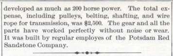
5 The Potsdam Red Sandstone Company s Water Wheel In Scientific American, Vol. LXVIII, No. 3, January 21, 1893, pp In a recent issue of this paper we illustrated the Potsdam stone quarries of this State. In one of the cuts a water wheel was shown, to which we alluded as employed for developing power for running the machinery of the works. This wheel was designed by a member of the firm of the Potsdam Red Sandstone Company. Its simplicity and efficiency entitle it to consideration, independent of the fact that the position in which it is placed involves special difficulties in operation. The river on which it is located is subject to freshets and varies at times greatly in the level, in the spring sometimes rising 6 feet. The stream is also used for logging, 200,000 logs passing down it in a season. These sometimes jam, and quantities of the logs strike the wheel and pass under it, the wheel rising to let them pass. The wheel has been in operation for several years, yet in all this time it has never broken a paddle. The wheel proper is an undershot wheel of the simplest possible construction. The hubs or flanges for carrying the arms are keyed to the shaft, as shown in the cut, Fig. 2. To further stiffen the shaft, three struts are placed equidistant around its center, over which tension rods with turn buckles are carried, as shown in this view and also in Fig. 3. The wheel is destitute of framing to take up twist. In place of such framing a wire rope is carried spirally half way around the wheel, just inside the paddles, to which it is fastened. This compels the end of the wheel next (sic) the gear to keep up with the other end. The rope is found to answer the purpose perfectly. The shaft of the wheel is made of rock elm, and is 24 inches in diameter. At the ends it is trimmed down for journals, and over the portion thus reduced in thickness pieces of 15-inch iron pipe are driven. The outer portion thus treated forms a journal two feet long; the inner portion is 6½ feet long. The wheel is 18 feet in diameter and 41 feet long. The paddles are 20 inches wide and the full length of the wheel, each being in one piece. The arms are of 4x7 inch water elm. The wheel axle is carried on trunnion blocks made of timber 20 inches square. The trunnion blocks are suspended by ropes, which, passing over pulleys in a stationary frame rising above the top of the wheel, terminate in counterweights, thus supporting the weight of the wheel. Everything now is in condition to keep the wheel at the same level as regards the water, whether it rises or falls. In the large engraving the trunnion block and counterweighting arrangement for the outer end of the wheel shaft is shown. A similar mechanism is contained within the house for the other end of the shaft. In Fig. 4 of the sectional drawing the arrangement of counterweighting is shown more in detail. The end of the shaft is carried into the house and on it a gear wheel 10 feet in diameter, with teeth of 2 ½ inches pitch, is placed. It is obvious that as the wheel rises and falls this gear wheel will, of course, do the same. The arrangement shown in Fig. 5 is for the purpose of enabling it, in spite of the changing of position, to operate a fixed countershaft. A wooden frame of heavy timber has one end journaled upon the shaft, so as to inclose within itself the 10 foot gear wheel. On the same frame a 10 inch gear wheel engaging with the larger one is journaled. This gear wheel turns a 5 foot band wheel attached to its own shaft. From the band wheel a belt goes to a fixed band wheel near the ceiling, which, by mitering gear, turns a grooved rope pulley for the
6 power-transmission cable. On the further end of the frame a box is placed to receive material for proper counterweighting. This counterweight keeps the belt stretched An examination of Fig. 5 of the cut will explain the entire arrangement. As the water wheel rises and falls, the counterweight executes the reverse movements. The 12 inch gear wheel and 5 foot band wheel change in position a little as these movements take place, but the counterweight keeps the belt always stretched, and the two gear wheels are always at a fixed distance from each other, as they are both attached to a rigid frame. The grooved sheave for the transmission rope is 10 feet in diameter, and normally runs at 200 revolutions per minute. The gear wheel on the end of the shaft of wood with iron segments bolted on, and is of 8 inch face, as is also the 10 inch pinion with which it engages. The fastest speed of the wheel is thirteen revolutions per minute, its lowest speed is six revolutions. It has developed as much as 200 horse power. The total expense, including pulleys, belting, shafting, and wire rope for transmission, was $2,500. The gear and all the parts have worked perfectly without noise or wear. It was built by regular employees of the Potsdam Red Sandstone Company.
Mechanical engineering
 REVIEW 13 ANSWER KEY Mechanical engineering Checkup 1 WHAT IS MECHANICAL ENGINEERING? (p. 426) 1. Name the branch of science and technology that focuses specifically on the study of technical objects with
CONTENT. 1. Syllabus 2. Introduction 3. Shaft 4. Coupling. Rigid coupling. Flange coupling. Sleeve (or) muff coupling Split muff coupling
 muff coupling Split muff coupling") UNIT II 1. Syllabus 2. Introduction 3. Shaft 4. Coupling Rigid coupling CONTENT Flange coupling Protected flange coupling Unprotected flange coupling Marine type flange coupling Sleeve (or) muff coupling
UNIT II 1. Syllabus 2. Introduction 3. Shaft 4. Coupling Rigid coupling CONTENT Flange coupling Protected flange coupling Unprotected flange coupling Marine type flange coupling Sleeve (or) muff coupling
HYBRID LINEAR ACTUATORS BASICS
 HYBRID LINEAR ACTUATORS BASICS TECHNICAL OVERVIEW Converting the rotary motion of a stepping motor into linear motion can be accomplished by several mechanical means, including rack and pinion, belts and
OWNER S MANUAL TRAIL BLAZERS
 OWNER S MANUAL TRAIL BLAZERS LOEGERING 800-373-5441 15514 37 th Street SE 701-347-5441 Casselton, ND 58012 USA Fax: 701-347-4323 E-Mail: lmi@loegering.com Internet: www.loegering.com Owners Manual, Track,
MECHANISMS. AUTHORS: Santiago Camblor y Pablo Rivas INDEX
 MECHANISMS AUTHORS: Santiago Camblor y Pablo Rivas INDEX 1 INTRODUCTION 2 LEVER 3 PULLEYS 4 BELT AND PULLEY SYSTEM 5 GEARS 6 GEARS WITH CHAIN 7 WORM GEAR 8 RACK AND PINION 9 SCREW AND NUT 10 CAM 11 ECCENTRIC
OPERATIONS & MAINTENANCE MANUAL KENNETH WALKER OBSERVATORY AT DEMIGUEL ELEMENTARY SCHOOL
 OPERATIONS & MAINTENANCE MANUAL KENNETH WALKER OBSERVATORY AT DEMIGUEL ELEMENTARY SCHOOL Department of Mechanical Engineering April 23, 2010 1 TABLE OF CONTENTS Dome Rotation Overview... 3 Maintenance...
LESSON Transmission of Power Introduction
 LESSON 3 3.0 Transmission of Power 3.0.1 Introduction Earlier in our previous course units in Agricultural and Biosystems Engineering, we introduced ourselves to the concept of support and process systems
FRICTION DEVICES: DYNAMOMETER. Presented by: RONAK D. SONI Assistant Professor Parul Institute of Technology, Parul University
 FRICTION DEVICES: DYNAMOMETER Presented by: RONAK D. SONI Assistant Professor Parul Institute of Technology, Parul University DYNAMOMETER A dynamometer is a brake but in addition it has a device to measure
(POWER TRANSMISSION Methods)
") UNIT-5 (POWER TRANSMISSION Methods) It is a method by which you can transfer cyclic motion from one place to another or one pulley to another pulley. The ways by which we can transfer cyclic motion are:-
UNIT-5 (POWER TRANSMISSION Methods) It is a method by which you can transfer cyclic motion from one place to another or one pulley to another pulley. The ways by which we can transfer cyclic motion are:-
Folding Golding. Precision High Speed Travel Wheel
 Folding Golding Precision High Speed Travel Wheel Instruction Manual Your new Folding Golding Travel Wheel was designed and handbuilt by Golding Fiber Tools. It has the same precision engineering, fine
OWNER S MANUAL. LOEGERING th Street SE Casselton, ND USA Fax:
 OWNER S MANUAL TRAIL BLAZERS and D SERIES TRACKS LOEGERING 800-373-5441 15514 37 th Street SE 701-347-5441 Casselton, ND 58012 USA Fax: 701-347-4323 E-Mail: lmi@loegering.com Internet: www.loegering.com
Rotary heat exchanger EURA split rotor, sizes 50 53
 Delivery units Sizes 50 53 are always supplied as two delivery units with a split rotor; see Fig. 2. Measurement nipples 1835 Fig. 1 Fig. 2 Dimensions and weights 3348 ø D Service access space D/2 Lifting
300 SERIES STANDARD DUTY CURVED TRACK
 300 SERIES STANDARD DUTY CURVED TRACK COMPLETE TRACK MODEL NUMBERS 301A 301W 316A 316W 328A 328W 300B SERIES BLACK CURVED TRACK COMPLETE TRACK MODEL NUMBERS 301AB 301WB 316AB 316WB 328AB 328WB SINGLE CARRIER
ELEVATOR TRACTION MACHINE ASSEMBLY ARRANGEMENT ABOVE ELEVATOR COUNTERWEIGHT AND CAR
 1 ELEVATOR TRACTION MACHINE ASSEMBLY ARRANGEMENT ABOVE ELEVATOR COUNTERWEIGHT AND CAR This invention is specially devised in order to provide arrangement plan of an elevator traction machine above elevator
SUPER 47A CLEANER PARTS SET UP WITH BRUSH SCREEN CLEANING GROUP DRAWING NUMBER
 SUPER 47A CLEANER PARTS SET UP WITH BRUSH SCREEN CLEANING PAGE GROUP DRAWING NUMBER.1 Thru 6.. 7.....8..9.10.....11.12.13 Thru 14.....15A.16 Thru 23..24.25 Thru 29..30A.31 Thru 32...33 Brush Adjusting
Mechanical engineering
 ST Questions 1, 2, 4, 7 13, 15 17, A, C and E Checkup 1 WHAT IS MECHANICAL ENGINEERING? (p. 426) 1. Name the branch of science and technology that focuses specifically on the study of technical objects
LIGHT BALL CLUTCH Lifelong Engineering and Development, Inc.
 Lifelong International Bowling, Inc. Worlds Leader in High Performance Specialty Parts LL300-202 Instructions LIFELONG INTERNATIONAL BOWLING, INC. LIGHT BALL CLUTCH Your new LIGHT BALL CLUTCH is designed
OWNER S MANUAL Z SERIES TRACKS. Rev. 355_05
 OWNER S MANUAL Z SERIES TRACKS Rev. 355_05 LOEGERING 800-373-5441 15514 37 th Street SE 701-347-5441 Casselton, ND 58012 USA Fax: 701-347-4323 E-Mail: lmi@loegering.com Internet: www.loegering.com Loegering
TRASH RACK CLEANING MACHINE
 TRASH RACK CLEANING MACHINE 1 SCOPE The work includes the design, manufacturing, supply, transportation, handling, storage, installation (including 1 st and 2 nd Stage embedded parts and any other necessary
Water handling and water power devices, propeller wheel and steering device.
 SECTION VIII NOB. us 1*8 Water handling and water power devices, propeller wheel and steering device. 52 THE NEWARK MUSEUM Section VIII 113. Old oaken bucket. This is the first known method of raising
Moments. It doesn t fall because of the presence of a counter balance weight on the right-hand side. The boom is therefore balanced.
 Moments The crane in the image below looks unstable, as though it should topple over. There appears to be too much of the boom on the left-hand side of the tower. It doesn t fall because of the presence
MANUAL TRANSMISSION SERVICE
 MANUAL TRANSMISSION SERVICE Introduction Internal combustion engines develop very little torque or power at low rpm. This is especially obvious when you try to start out in direct drive, 4th gear in a
AGE 222. Introduction to Farm Machinery Dr. O. U. Dairo. Farm Machinery and Power
 AGE 222 Introduction to Farm Machinery Dr. O. U. Dairo Farm Machinery and Power Equipment in the farm are classified as farm power and farm machinery Power provides pull/force required tom operate implements
not new, but we made it a point to be sure that used components were of good quality. Precision is essential.
 Ox Power Unit INTRODUCTION In this article we will describe how we built an ox-driven, sweep-powered generator. The concepts behind the design and operation of this unit are not new or complicated. Throughout
Driver Driven. InputSpeed. Gears
 Gears Gears are toothed wheels designed to transmit rotary motion and power from one part of a mechanism to another. They are fitted to shafts with special devices called keys (or splines) that ensure
READ AND SAVE THESE INSTRUCTIONS. Centrifugal Downblast Exhaust Fan Belt Driven for Roof & Wall Mounting
 READ AND SAVE THESE INSTRUCTIONS INSTALLATION, OPERATING INSTRUCTIONS & PARTS MANUAL Centrifugal Downblast Exhaust Fan Belt Driven for Roof & Wall Mounting Electrical wiring and connections should be done
SUPER 47D CLEANER PARTS SET UP WITH BRUSH SCREEN CLEANING GROUP DRAWING NUMBER
 SUPER 47D CLEANER PARTS SET UP WITH BRUSH SCREEN CLEANING PAGE GROUP DRAWING NUMBER..1...2...3..4....5 & 6..7.....8..9.10.....11.12.13 Thru 14.....15A.16 Thru 23..24..25..26.27 Thru 29...30A.31 Thru 32...33
Section 13. Tail Rotor Drive. RotorWay International A600 TALON Construction Manual. Section 13. Page A
 RotorWay International Page A Tail Rotor Drive Procedures covered in this section: Install driveshafts and gearboxes; install drive belt and tensioner; fabricate and install tail rotor pitch actuator arms;
Top Down Rollstar Shade Installation Instructions
 Top Down Rollstar Shade Installation Instructions Thank you for purchasing your new Rollstar shade. It has been custom-made from the highest quality materials to the dimensions you specified. With proper
600 SERIES STANDARD DUTY STRAIGHT TRACK INSTALLATION INSTRUCTIONS
 600 SERIES STANDARD DUTY STRAIGHT TRACK INSTALLATION INSTRUCTIONS PLEASE READ INSTRUCTIONS THOROUGHLY BEFORE BEGINNING. A. BI-PARTING TRAVEL 1. Before raising track into position, determine location of
Regulation for Installing
 Regulation for Installing Phase Conductors and Earth Wires, as well as OPGW/OPPC (PCEWOP) made from aluminium, aluminium alloy, steel, aluminium clad steel, HACIN and combinations of these materials with
SUSPENSION - REAR Toyota Celica DESCRIPTION ADJUSTMENTS & INSPECTION WHEEL ALIGNMENT SPECIFICATIONS & PROCEDURES WHEEL BEARING
 SUSPENSION - REAR 1988 Toyota Celica REAR SUSPENSION Toyota IRS DESCRIPTION The Toyota Independent Rear Suspension (IRS) system utilizes MacPherson struts, which fasten to axle carrier and wheel housing.
"CRANE SAFETY IN CONSTRUCTION ENVIRONMENTS"
 PRESENTER'S GUIDE "CRANE SAFETY IN CONSTRUCTION ENVIRONMENTS" Part of the "CONSTRUCTION SAFETY KIT" Series Quality Safety and Health Products, for Today...and Tomorrow OUTLINE OF MAJOR PROGRAM POINTS OUTLINE
Pontoon Assembly Instructions and manual. Read before using hoist.
 Page 1 Pontoon Assembly Instructions and manual. Read before using hoist. For Models 32BL18, 32BL22, 32BL25 and 42BL28 R Model 32BL22 Shown Proudly Made in Michigan By NuCraft Metal Products 402 Southline
Clock and watch escapements, power stamps and hammers, power punch, rotary conveyer, blower, pile driver and miscellaneous devices.
 K»\ IX Nos. 1-21) 144 Clock and watch escapements, power stamps and hammers, power punch, rotary conveyer, blower, pile driver and miscellaneous devices. MECHANICAL MODELS 57 Section IX 129. Clock escapement.
LADDERS If the top of the ladder is secured to Do not throw tools or materials to a craftsman
 BSP 460-300 108-i01_1969 12 0l.jpg Scanned by Frank Harrell, (Cowboy Frank) Castle Rock, Colorado Oct 07, 2012 21:15:33 BELL SYSTEM PRACTICES Plant Series SECTION 460-300-108 Issue 1, December 1969 AT&TCo
accidents which arise due to nonobservance and the safety information herein.
 2000LB WINCH Model: 7247 CALIFORNIA PROPOSITION 65 WARNING: You can create dust when you cut, sand, drill or grind materials such as wood, paint, metal, concrete, cement, or other masonry. This dust often
LINK-BELT MODEL HTC-8675LB - 75 TON CAPACITY 48 7" (.80m) 41 0" /8" (3.52m) /16" (2.02m) /4" (.34m) 25" 11 0" (.
 41 0 /8 (3.52m) /16 (2.02m) /4 (.34m) 25 11 0 (.") LIFTING CHARTS - Hydraulic Truck Cranes LINK-BELT MODEL - 75 TON CAPACITY 41 0" (12.50m) 48 7" (14.80m) C L Of Rotation 13 8 1/8" (4.17m) 7 0" (2.13m) 4 5/8" (118mm) 11 6 7/8" (3.52m) 6 7 11/16" (2.02m)
LIFTING CHARTS - Hydraulic Truck Cranes LINK-BELT MODEL - 75 TON CAPACITY 41 0" (12.50m) 48 7" (14.80m) C L Of Rotation 13 8 1/8" (4.17m) 7 0" (2.13m) 4 5/8" (118mm) 11 6 7/8" (3.52m) 6 7 11/16" (2.02m)
2005 Hyundai Tucson LX. On some models, engine is equipped with a timing belt and timing chain. Inspect timing chain when replacing timing belt.
 TIMING BELT NOTE: On some models, engine is equipped with a timing belt and timing chain. Inspect timing chain when replacing timing belt. Removal 1. Remove the engine cover. See Fig. 1. 2. Remove right
Star Windmill History
 Star Windmill History Used in most parts of the US and exported to numerous foreign countries, the ORIGINAL STAR solid wheel wooden windmill was the second most popular wooden windmill on the Great Plains
Module 5: Cooling Fundamentals
 Terms and Definitions Major Mechanical Parts of a Four Speed Auto Transmission Parts of a Planetary Gear System Planetary Gear System Operation Speed, Torque, and Directional Function Fluid Pump and Pressure
ENGINE MECHANICAL <134>
 11A-1 GROUP 11A ENGINE MECHANICAL CONTENTS GENERAL INFORMATION........ 11A-2.................. 11A-3 11A-2 The newly developed 1.1L 134910 engine features 3-cylinder, 12-valve, and double overhead
WARM ENGINE STARTING PROCEDURE
 saw starting COLD ENGINE STARTING PROCEDURE 1. Pull the choke lever out. 2. Lock the throttle in the start position by depressing and holding the throttle lock button (C) while releasing the trigger (A)
Head Terminal Repair Parts. Hopper Repair Parts
 Head Terminal Repair Parts #61686200 - Mild Steel 1 1 61685400 6" Lagged Roller 2 1 81498800 Head Terminal Weldment 3 2 03018900 Bearing 1 5/16" Flange 4 1 14979900 CRR 1 5/16" x 20 13/16" 5 2 12003000
ME6601 DESIGN OF TRANSMISSION SYSTEMS
 SYED AMMAL ENGINEERING COLLEGE (Approved by the AICTE, New Delhi, Govt. of Tamilnadu and Affiliated to Anna University, Chennai) Established in 1998 - An ISO 9001:2008 Certified Institution Dr. E.M.Abdullah
Take off case cover.
 33 14 520 Removing complete locking differential. (Type K) - final drive removed - Removing and installing final drive, refer to 33 10 010 Drain off fluid. Secure final drive to special tool 33 1 010 (retaining
1990 SUSPENSION Front ES250, LS400
 SUSPENSION - FRONT Article Text 1990 Lexus LS 400 For Lextreme Copyright 1998 Mitchell Repair Information Company, LLC Thursday, January 29, 2004 04:56PM ARTICLE BEGINNING 1990 SUSPENSION Front ES250,
Marine Engineering Exam Resource Review of Couplings
 1. What are rigid couplings used for? Used to join drive shafts together. True alignment and rigidity are required. Example Drive shafts and production lines, bridge cranes, solid shaft that needs to be
14.4 Simple Machines. The output of one device acts as the input of the next.
 The output of one device acts as the input of the next. What are the six types of simple machines? The six types of simple machines are the lever, the wheel and axle, the inclined plane, the wedge, the
.3 Section Vibration Isolation and Seismic Control..2 ANSI/AMCA 210/ASHRAE 51 Laboratory Methods of Testing Fans for Rating.
 Issued 2005/06/01 Section 15831 Commercial Fans Page 1 of 6 PART 1 GENERAL 1.1 RELATED SECTIONS.1 Section 01355 Waste Management and Disposal..2 Section 15053 Motors, Drives and Guards..3 Section 15072
REMOVAL & INSTALLATION
 REMOVAL & INSTALLATION TIMING BELT Removal 1. Disconnect negative battery cable. On Millenia, raise and support vehicle. Remove right front wheel. Remove lower engine covers. 2. On all models, remove accessory
Operating Instructions For Your LUG-ALL Cable Winch-Hoist
 LAC-0108 Rev. 5/08 Operating Instructions For Your LUG-ALL Cable Winch-Hoist 604 Hemlock Road, Morgantown, PA 19543 Phone: (877) 658-4255 / Fax: (610) 286-9661 / Web: www.lug-all.com Copyright 2008 LUG-ALL
PRESENTER'S GUIDE "CRANE SAFETY" Part of the "SAFETY MEETING KIT" Series Quality Safety and Health Products, for Today...
 PRESENTER'S GUIDE "CRANE SAFETY" Part of the "SAFETY MEETING KIT" Series Quality Safety and Health Products, for Today...and Tomorrow OUTLINE OF MAJOR PROGRAM POINTS OUTLINE OF MAJOR PROGRAM POINTS The
UNIT -I. Ans: They are specified by the no. of strands & the no. of wires in each strand.
 VETRI VINAYAHA COLLEGE OF ENGINEERING AND TECHNOLOGY, THOTTIAM, NAMAKKAL-621215. DEPARTMENT OF MECHANICAL ENGINEERING SIXTH SEMESTER / III YEAR ME6601 DESIGN OF TRANSMISSION SYSTEM (Regulation-2013) UNIT
SUPER 49B SET UP WITH BR PAGE NUMBER
 SUPER 49B SET UP WITH BR PAGE NUMBER..1...2...3..4....5 & 6..7.....8..9.10.....11.12.13 Thru 14.....15A.16 Thru 23..24...25A..26.27 Thru 29...30.31 Thru 32...33 ITEM PAGE PART NO. NO. NUMBER QTY. All 26
FRICK TIMBER TIGER SAWMILLS SIZES: 0 0C
 FRICK TIMBER TIGER SAWMILLS SIZES: 0 0C SERVICE S LIST PAGE 2 TIMBER TIGER 0 AND 0C SAWMILLS HOW TO USE S LIST This Parts List provides identification of Frick Timber Tiger s 0 and 0C Standard Sawmills
Stillwater Vertical Lift Bridge Rehabilitation
 Paper No. 33 Machinery/Mechanics Stillwater Vertical Lift Bridge Rehabilitation Todd Owens, P.E. HNTB Corporation TENTH BIENNIAL SYMPOSIUM OCTOBER 25-28, 2004 The Omni Orlando Resort at ChampionsGate Abstract
JRC ENGINEERING INC 3110 Indian Ave Suite E Perris, California
 JRC ENGINEERING INC 3110 Indian Ave Suite E Perris, California 92571 800-634-3250 Thank you for choosing our 750 conversion for your Triumph 650. Careful assembly and running in will greatly extend the
Pulley Alignment. Parallel Misalignment
 Pulley Alignment There are many different factors that contribute to machine downtime when considering Sheave/Pulley, Belt and Bearing wear. The single biggest factor that can impact the reliability of
ADVANCED SPOOLING TECHNOLOGY LEBUS KNOWS HOW
 ADVANCED SPOOLING TECHNOLOGY LEBUS KNOWS HOW RENOWNED THROUGHOUT THE WORLD FOR ITS EXPERIENCE AND OUTSTANDING SPOOLING TECHNOLOGY LEBUS WILL HELP YOU WIND UP ALL YOUR PROBLEMS. THE ORIGINAL LEBUS SPOOLING
Introduction to Manual Transmissions & Transaxles
 Introduction to Manual Transmissions & Transaxles Learning Objectives: 1. Identify the purpose and operation of transmissions. 2. Describe torque and torque multiplication. 3. Determine gear ratios. 4.
TENSOREX C+ Spring Automatic Tensioning Device for Railway and Tramway Overhead Contact Lines. the power connection THE PFISTERER GROUP
 Spring Automatic Tensioning Device for Railway and Tramway Overhead Contact Lines THE PFISTERER GROUP the power connection Constant Tension from a Compact Design The overhead contact lines of railways
AUTO REWIND AIR HOSE REEL
 Model #s 46845, 46848 AUTO REWIND AIR HOSE REEL OPERATOR S MANUAL STORE THIS MANUAL IN A SAFE PLACE FOR FUTURE REFERENCE!? NEED HELP? Save time, contact us first. 888-648-8665 support@tekton.com WARNING:
Twin Screw Undercar Conveyor
 Twin Screw Undercar Conveyor Owner s Manual #19015700 05-00 Table of Contents Operator Qualifications...................................... 1 Safety.................................................. 2-4
All levers are one of three types, usually called classes. The class of a lever depends on the relative position of the load, effort and fulcrum:
 Página 66 de 232 Mechanisms A mechanism is simply a device which takes an input motion and force, and outputs a different motion and force. The point of a mechanism is to make the job easier to do. The
MAINTENANCE MANUAL DP-265
 MAINTENANCE MANUAL DP-265 Drive Gears Sisu Axles, Inc. Autotehtaantie 1 P.O. Box 189 FIN-13101 Hämeenlinna Finland Phone int + 358 204 55 2999 Fax int + 358 204 55 2900 DP265DG.PDF (2/2003) k Table of
Stopping Accuracy of Brushless
 Stopping Accuracy of Brushless Features of the High Rigidity Type DGII Series Hollow Rotary Actuator The DGII Series hollow rotary actuator was developed for positioning applications such as rotating a
A B C D E F. Tools Required (supplied by others)
") Page 1 of 17 Parts List Below Deck Automatic Retractable Security Cover Kit (1) Tube End Bearing Plate (A) (1) Rope Reel and Cover Drum Motor Assembly (B) (1) Cover Drum (1) Pulley Support Channel (2)
Page 1 of 17 Parts List Below Deck Automatic Retractable Security Cover Kit (1) Tube End Bearing Plate (A) (1) Rope Reel and Cover Drum Motor Assembly (B) (1) Cover Drum (1) Pulley Support Channel (2)
ENGINE CLUTCH CONTENTS OF THIS SECTION
 ENGINE CLUTCH 6C-l ENGINE CLUTCH CONTENTS OF THIS SECTION SUBJECT General Description Periodic Service Adjustments on Car Removal of Clutch Inspection of Clutch Parts Installation of Clutch Specifications
1. General Description
 General Description 1. General Description A: SPECIFICATION 1. PROPELLER SHAFT Propeller shaft type 3UJ Front propeller shaft Joint-to-joint length: L 1 mm (in) 633 (24.92) Rear propeller shaft Joint-to-Joint
Scissor Lift Model : SC60 SC40 Installation Instructions
 Scissor Lift Model : SC60 SC40 Installation Instructions 0 XLT SCISSOR LIFT INSTALLATION INSTRUCTIONS Please read installation instructions carefully before installation and keep it for future reference.
INSTALLATION INSTRUCTIONS
 COLD AIR INTAKE INSTALLATION INSTRUCTIONS PART NUMBER D760-0390C APPLICATION: 1999-2003 E39 M5 PARTS LIST 1 Left Aluminum Intake Tube 1 Air Pump Bracket (A) 1 Right Aluminum Intake Tube 1 Air Pump Bracket
DRIVE AXLE Nissan 240SX DESCRIPTION & OPERATION AXLE RATIO & IDENTIFICATION AXLE SHAFT & BEARING R & I DRIVE SHAFT R & I
 DRIVE AXLE 1990 Nissan 240SX 1990 DRIVE AXLES Rear Axle - R200 240SX, 300ZX DESCRIPTION & OPERATION The axle assembly is a hypoid type gear with integral carrier housing. The pinion bearing preload adjustment
Hoists & Winches. :: Electric Chain Hoists 26 :: Manual Hoists 30 :: Pneumatic Hoists 31 :: Winches 32 :: Beam Trolleys 34
 Hoists & Winches Lifting & Handling Equipment :: Electric Chain Hoists 26 :: Manual Hoists 30 :: Pneumatic Hoists 31 :: Winches 32 :: Beam Trolleys 34 Electric Chain Hoists Compact Electric Chain Hoists
DIAMOND ROLLER CHAIN. For Agricultural and Construction Equipment
 DIAMOND ROLLER CHAIN For Agricultural and Construction Equipment FABRICATION While roller chain would appear to be a simple product, the number of components in a ten foot section of 40 pitch chain totals
With the help of the impact gun it was a piece of cake to remove the 36mm axle nut. Without it I would be still trying
 Let s start renewing parts. As a first step I chose to deal with the front of the ABS system by rebuilding and restoring front wheel hubs & halfshafts. The main difference compared to the non-abs version
BOLT PLANT (Automatic)
") BOLT PLANT (Automatic) (a) Automatic High Speed Double Stroke Cold Heading Machines (b) Automatic Bolt Head Trimming and Shank Reducing Machines (c) Automatic Thread Rolling Machines (High Speed) DOUBLE
BOLT PLANT (Automatic) (a) Automatic High Speed Double Stroke Cold Heading Machines (b) Automatic Bolt Head Trimming and Shank Reducing Machines (c) Automatic Thread Rolling Machines (High Speed) DOUBLE
INSTRUCTION MANUAL & PARTS BOOK. Vibratory Screed
 INSTRUCTION MANUAL & PARTS BOOK Vibratory Screed 200 COMMERCE DRIVE, FREEHOLD, NEW JERSEY, USA, 07728, 732-566-5400 FAX 732-5444 Doc. # OI-M09201 Current Rev. 07 Revised: 11/2013 Orig. Rel.: 06/2014 SAFETY
READ AND SAVE THESE INSTRUCTIONS. Centrifugal Upblast Exhaust Fan (Standard & High Pressure Exhaust) Belt Driven for Roof & Wall Mounting
 Belt Driven for Roof & Wall Mounting") READ AND SAVE THESE INSTRUCTIONS INSTALLATION, OPERATING INSTRUCTIONS & PARTS MANUAL Centrifugal Upblast Exhaust Fan (Standard & High Pressure Exhaust) Belt Driven for Roof & Wall Mounting Electrical wiring
READ AND SAVE THESE INSTRUCTIONS INSTALLATION, OPERATING INSTRUCTIONS & PARTS MANUAL Centrifugal Upblast Exhaust Fan (Standard & High Pressure Exhaust) Belt Driven for Roof & Wall Mounting Electrical wiring
Timing-Belt Reverse Unit 8 80 R25 Notes on Use and Installation
 Timing-Belt Reverse Unit 8 80 R25 Notes on Use and Installation Content General General hazard warning 2 Appropriate use 3 Content Application 3 Technical Data/Scope of Supply 3 Application Options 4 Fitting
ELECTRIC WIRE ROPE HOIST and TROLLEY RHN SERIES
 EFFECTIVE: October 21, 2011 ELECTRIC WIRE ROPE HOIST and TROLLEY RHN SERIES 2 Ton through 20 Ton Capacity Hoist Code and Serial Number This equipment should not be installed, operated or maintained by
PYRTE. Building The Front Axle, Fork and Steering
 PYRTE Building The Front Axle, Fork and Steering The front axle on this traction engine is a very simple affair, in that it is a rectangular steel rod, sat on edge, with a pivot in the centre, which is
Howard Tarmac Sweeper HTS
 2 Howard Tarmac Sweeper HTS Serial Number The Serial and Model numbers are stamped on the frame of your TARMAC SWEEPER. For future reference record the numbers. ALWAYS quote them when ordering spareparts.
SIDNEY MANUFACTURING
 SIDNEY MANUFACTURING SIDE WALL RETURNTM DRAG CONVEYOR INSTALLATION INSTRUCTIONS NOTICE BEFORE ANY MAINTENANCE OR SERVICE IS PERFORMED ON THIS DRAG CONVEYOR, IT MUST BE LOCKED OUT IN ACCORDANCE WITH CURRENT
SUPER 248BDH WITH BRUSHES
 SUPER 248BDH WITH BRUSHES PAGE DESCRIPTION NUMBER..1...2...3..4 B 5..6 A.7..7 A 8.9...10..11 & 12....13 B.... 14 B....15C.....16 B 17 Thru 23.24.25A.26 27 28.29... 30 31 32 Front Air Damper.. Back Air
Mechanical Equipment - Course 230.1
 Mechanical Equipment - Course 230.1 BELT DRIVES A conunon method of transmitting power is a combination of belts and pulleys, There are many types of belts and pulleys used for the transmission of power
Cranes. OSHA Office of Training & Education 1
 Cranes OSHA Office of Training & Education 1 Major Causes of Crane Accidents Contact with power lines Overturns Falls Mechanical failures OSHA Office of Training & Education 2 How Do Accidents Occur? Instability
INSTRUCTION G-Comp Unser Edition Rear Suspension: Chevy Nova. Kit Contents:
 INSTRUCTION 350-400 G-Comp Unser Edition Rear Suspension: 62-67 Chevy Nova Speedway Motors, Inc. 2017 Kit Contents: 350003.1 G-Comp Chassis Brace 350003.2 G-Comp Front Support 350400.1 Chevy II Unser Rear
Graphical representation of a gear
 Homework 4 Gears Gears are designed to transmit rotary motion. Often they are arranged in a gear train (meshed together). Gear trains provide a change in speed, torque (turning force) and direction (clockwise
KONE EcoMod Escalator Maintenance Instructions
 6 COMBPLATE MAINTENANCE MODULE Suggested maintenance schedule for Combplate Module is one to two times per year, dependent upon escalator use. 6.1 Check and adjust combplate impact device Complete the
159 North Maple St. Unit J, CORONA CA P F
 159 North Maple St. Unit J, CORONA CA 92880 P. 951-737-9682 F. 951-737-9006 WWW.CHAOSFAB.COM 2005+ Tacoma 4WD/Pre-Runner Rear Mid-Travel Spring-Under Installation Instructions Part#86450 Leaf Spring Note:
Your interest is appreciated and hope the next 37 pages offers great profit potential for your new business. Copyright 2017 Frank Seghezzi
 Description and comparison of the ultimate new power source, from small engines to power stations, which should be of interest to Governments the general public and private Investors Your interest is appreciated
I N ST R UC T I ON MODEL 5614 MEAT SAW MODEL ML (Starting Serial Number ) FORM Rev. A (11-95) MEAT SAWS
 FORM Rev. A (11-95) MEAT SAWS") I N ST R UC MEAT SAWS T I ON S MODEL 5614 MEAT SAW MODEL 5614 ML-19553 (Starting Serial Number 27-128-712) EXECUTIVE OFFICES 701 RIDGE AVENUE TROY, OHIO 45374-0001 FORM 16992 Rev. A (11-95) Installation,
I N ST R UC MEAT SAWS T I ON S MODEL 5614 MEAT SAW MODEL 5614 ML-19553 (Starting Serial Number 27-128-712) EXECUTIVE OFFICES 701 RIDGE AVENUE TROY, OHIO 45374-0001 FORM 16992 Rev. A (11-95) Installation,
Model E600 Tarping System
 10 Boulder Parkway N. Oxford, MA 01537 866-353-5826 pioneersales@wastequip.com www.pioneercoverall.com Model E600 Tarping System Installation Instructions WARNING: In order to prevent damage, the tarp
SECTION 8 BEVEL GEARING
 SECTION 8 BEVEL GEARING For intersecting shafts, bevel gears offer a good means of transmitting motion and power. Most transmissions occur at right angles, Figure 8-1, but the shaft angle can be any value.
TORQUE LIMITER SERIES 200
 TORQUE LIMITER SERIES 200 Quality and Autogard are synonymous with overload protection. The company's reputation for high quality products is derived from over 40 years of design innovation and production.
Installation Manual TWM Performance Short Shifter Cobalt SS/SC, SS/TC, HHR SS, Ion Redline and Saab 9-3
 Page 1 Installation Manual TWM Performance Short Shifter Cobalt SS/SC, SS/TC, HHR SS, Ion Redline and Saab 9-3 Please Note: It is preferable to park on a flat surface, as you will have to engage and disengage
Gear Drives. A third gear added to the system will rotate in the same direction as the drive gear Equal diameters = Equal number of teeth = Same speed
 Gear Drive Systems Gear Drives Gear Drive: Synchronous mechanical drive that uses gears to transfer power Gear: A toothed wheel that meshes with other toothed wheels to transfer rotational power Pinion
PowerAssist. Installation Manual
 PowerAssist Counterweight Assisted Hoist System Installation Manual Design, Manufacture and Installation of Theatrical Equipment Worldwide (315) 451-3440 Fax (315) 451-1766 www.jrclancy.com Table of Contents
Wide Band EFIE Installation Instructions. Locate the wide band oxygen sensor current wire
 Wide Band EFIE Installation Instructions Install your fuel efficiency device The EFIE is not intended to be a fuel saver by itself. You should install a device that is designed to get more energy out of