MAV Case IH AFX Series Complete Chopper Installation Guide
|
|
|
- Esmond Sparks
- 6 years ago
- Views:
Transcription
1 MV ase IH FX Series omplete hopper Installation Guide S _V0_June_2016
2 ase IH FX Series omplete Redekop MV hopper Installation Manual Table of ontents Section Safety 0 Pre-Installation 1 Hydraullic Line Modifications 2 Sieve xtension 3 Internal Deflectors 4 Factory Knifebar and oncave Setting 5 Straw Door 6 hopper Placement 7 Gas Springs and Speed Sensor 8 Ladder 9 Drive 10 Drive Shield 11 Hydraulic Oil Level 12 2

3 ase IH FX Series omplete Redekop MV hopper Installation Manual omponent Reference 2. Hydraulic Lines 3. Sieve xtension 4. Internal Deflectors Factory Knifebar & oncave Setting 9 6. Straw Door 7. hopper 8. Gas Springs & Speed Sensor 9. Ladder hopper Drive 11. Drive Shield 12. Hydraulic Oil Level Tailboard 3


4 Supplies required to assist during the installation procedure: Requirements: Marker Drill Drill bit - 9mm dia or 11/32 in dia. - required for section 3.3, Drill bit - 10mm dia or 13/32 in dia. - required for section 4.2 Drill bit - 12mm dia or 1/2 in dia. - required for section 3.1 Pipe Sealant Tape - required for section 2 Sand paper / emery cloth - required for section 10.5 Straight dge or Laser lignment Tool - approx mm long - required for section 10 Grinder - required for section 3.1 Purchase Purchase V elt from NH Parts: NH # V elt 3 x 10⁷L Kevlar HD or NH # V elt 3 x 10⁷L Kevlar - required for section

5 0 Safety 0.1 Introduction IMPORTNT: Read through this instruction thoroughly and familiarize yourself with the machine before removing these components. Do not skip steps or perform them out of order. This instruction manual explains the proper procedure for preparing the combine and removing the Factory Spreader omponents in order to install the Redekop MV hopper 0.2 Recognize Safety Information This is a safety-alert symbol. When you see this symbol on your machine or in this manual, be alert to the potential for personal injury. Follow recommended precautions and safe operating practices. 0.3 Understand Signal Words signal word - DNGR, WRNING, or UTION - is used with the safety-alert symbol. DNGR identifies the most serious hazards. WRNING or UTION safety signs are located near specific hazards or precautionary areas in this manual. 0.4 Follow Safety Instructions arefully read all safety messages in this manual and on your machine. Keep safety signs in good condition. Replace missing or damaged safety signs. e sure new equipment components and repair parts include the current safety signs. Replacement safety signs are available from your dealer. There can be additional safety information contained on parts and components sourced from suppliers that is not reproduced in this operator s manual. Learn how to operate the machine and how to use controls properly. Do not let anyone operate without instruction. Keep your machine in proper working condition. Unauthorized modifications to the machine may impair the function and/or safety and affect machine life. If you do not understand any part of this manual and need assistance, contact your dealer. Other languages are available for this machine. Please contact Redekop 5


6 0.5 Safe Operating Practices DO NOT stand near combine when machine is running. LWYS refer to your ombine Operator s Manual, and review Safety section before operating machine. The ombine Operator s Manual details safe operating practices that must be followed to protect you and others from accidental death and/or injury. Operate machine only when all guards are correctly installed. efore moving away, always check immediate vicinity of machine (e.g. for children). nsure adequate visibility. Use the horn as a warning immediately before moving away. When making turns, always take into consideration the width of the attachment and the fact that the rear end of the machine swings out. ttachments and ground conditions affect the driving characteristics of the combine. Never leave machine unattended as long as engine is running. 0.6 Work In Ventilated rea ngine exhaust fumes can cause sickness or death. If it is necessary to run an engine in an enclosed area, remove the exhaust fumes from the area with an exhaust pipe extension. If you do not have an exhaust pipe extension, open the doors and get outside air into the area. 0.7 Practice Safe Maintenance Understand service procedure before doing work. Keep area clean and dry. Never lubricate, service, or adjust machine while it is moving. Keep hands, feet, and clothing from powerdriven parts. Disengage all power and operate controls to relieve pressure. Lower equipment to the ground. Stop the engine. Remove the key. llow machine to cool. Securely support any machine elements that must be raised for service work. Keep all parts in good condition and properly installed. Fix damage immediately. Replace worn or broken parts. Remove any buildup of grease, oil, or debris. On self-propelled equipment, disconnect battery ground cable (-) before making adjustments on electrical systems or welding on machine. 6


7 0.8 void ontact With Moving Parts Keep hands, feet and clothing away from power driven parts. Never clean, lubricate or adjust machine when it is running. 0.9 void High-Pressure Fluids Inspect hydraulic hoses periodically at least once per year for leakage, kinking, cuts, cracks, abrasion, blisters, corrosion, exposed wire braid or any other signs of wear or damage. Replace worn or damaged hose assemblies immediately. scaping fluid under pressure can penetrate the skin causing serious injury. void the hazard by relieving pressure before disconnecting hydraulic or other lines. Tighten all connections before applying pressure. Search for leaks with a piece of cardboard. Protect hands and body from high-pressure fluids. If an accident occurs, see a doctor immediately. ny fluid injected into the skin must be surgically removed within a few hours or gangrene may result. Doctors unfamiliar with this type of injury should reference a knowledgeable medical source Dispose of Waste Properly Improperly disposing of waste can threaten the environment and ecology. Potentially harmful waste includes such items as oil, fuel, coolant, brake fluid, filters, and batteries. Use leakproof containers when draining fluids. Do not use food or beverage containers that may mislead someone into drinking from them. Do not pour waste onto the ground, down a drain, or into any water source Use Proper Lifting quipment Lifting heavy components incorrectly can cause severe injury or machine damage. Follow recommended procedure for removal and installation of components in the manual. nsure lifting equipment is rated for the job nsure operator is appropriately licensed to operate lifting equipment 7
8 0.12 Personal Protective quipment (PP) Qualified Person designated by the employer, who is knowledgeable about and familiar with all relevant specifications and assembly instructions and is capable of identifying existing or potential hazards in surroundings or working conditions which may be hazardous or dangerous to employees shall determine appropriate Personal Protective quipment required for this assembly. Personal Protective quipment (PP) are devices worn by the employees to protect against hazards in the environment. xamples include safety glasses, face shields, respirators, gloves, hard hats, steel-toe shoes, and hearing protection. Torque Table Nominal Size lass 8.8 lass 10.9 Nm / (ft-lbs) Nm / (ft-lbs) M8 - flanged 27 / (20) 39 / (29) - non flanged 25 / (18) 35 / (26) M10 - flanged 54 / (40) 57 / (42) - non flanged 49 / (36) 70 / (51) M12 - flanged 93 / (69) 134 / (98) - non flanged 85 / (63) 121 / (90) M16 - flanged 231 / (171) 331 / (244) - non flanged 210 / (155) 301 / (222) heck all fasteners to ensure they have been properly tightened 8
9 Kit ontent Ref Item Name Part # Qty ase IH hopper ssy Handle, ase IH FX S206 x1 x1 hopper Drive Shield S884 x1 D Straw Door 57L S136 x1 Sieve xtension H518 x1 F Jackshaft ssembly 3 FX Drive S711 x1 FX 120S Drive ompletion ox - 3 Drive FX Sheave PTO Driver ox - 3 Drive FX 120S Hyd. Non-Windrow ox FX ompletion ox FX Ladder omponents D F 9

 and sheave () 1.")
 D 1.")
 Disconnect spreader speed")

10 1 Pre-Installation 1.1 On the driver side of the combine: - Loosen belt tensioners () on the main drive belts - Remove belts () and sheave () 1.2 Rotate spreader to rearward position to prepare for removing spreader package (D) D 1.3 Disconnect chaff spreader proximity sensor (upper driver side) Disconnect spreader speed sensor (lower passenger side) ut cable ties for proximity switches and speed sensor Remove spreader speed sensors from hydraulic motors (D1) D1 D1 10
 is located in the rear zone as shown in dotted box, it will interfere with")
 from hydraulic block (F1) F1 1.5.")
11 1.4 Remove spreader hydraulic hoses () from hydraulic block (F) F or F Swing hose assembly () back onto spreader for storage 1.5 If hydraulic block (F) is located in the rear zone as shown in dotted box, it will interfere with the new jackshaft and will have to be removed Disconnect steel hydraulic lilnes (F1) from hydraulic block (F1) F Remove hydraulic block (F) from combine wall F 11


12 1.6 Loop hydraulic circuit Install new hydraulic rubber hose (J) into steel hydraulic lines (F1) to loop circuit F1 J Install new hydraulic rubber hose (J) into hydraulic block (F) to loop circuit or F F J 12


13 1.7 Remove gas spring (K) K Gas Spring is under load and will extend when released Remove sensor (L) - Save sensor for chopper assembly later M L 1.8 Place a pallet under spreader and lift into place with a fork lift to assist in removal of the spreader Remove pin and bolt (M) from one side and rest spreader on pallet to remove hardware from opposite side Lower pallet with spreader and store in a convenient location 1.9 Remove internal deflector panels (N) N N 13

 - remove gas shocks (R1)")
 - remove support")
 - remove top ladder plastic")

14 1.10 Remove straw door (P) - leave factory straw door brackets for mounting Redekop straw door Remove Ladder ssembly - ensure ladder is in upper position (R) - remove gas shocks (R1) - keep for reinstallation on new ladder - remove straw door hinge (R2) - remove support brackets (R3) - drop ladder - remove bottom hinge bolt (R4) - remove top ladder plastic roller support (front) - carefully swing out ladder from supports and lower to the ground P R R1 R2 R3 R4 14


, (S1)")
15 1.11 Remove spreader mount panels (S), (S1) & (S2) S S1 P S2 15
 U 1.")
 to factory fitting (Y) 1.14.3 Reattach hose to fittings (Z) - This moves the hose out of the way for the chopper belt drive V Y Z Z 16")
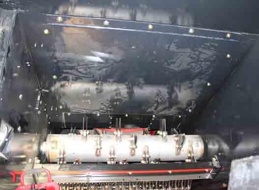
16 1.12 Remove bolts from flange (U) to prepare for chopper assembly 1.13 The inside panels should look like this after spreader, straw door, and delfector panels are removed (V) U 1.14 Disconnect hydraulic hose at (Y) ssemble 90 degree fittings (Z) - Steel 90 Degree Hydraulic Fitting (# H FFX) 10 FORSX-10MORF (Z) x ttach fittings (Z) to factory fitting (Y) Reattach hose to fittings (Z) - This moves the hose out of the way for the chopper belt drive V Y Z Z 16

 1 -")

 F - Upper Internal ccess")

17 2 Hydraulic line modifications 1 Reference: - Pump 1 - Pump onnection - Hydraulic Steel Tube (to be removed) 1 - Hydraulic Steel Tube onnection - Hydraulic Steel Tube lamp D - Hydraulic Hose Return Line onnection - Hydraulic line (fan side) F - Upper Internal ccess Panel G - Internal hopper Rotor H - Sieve D 1 F G H 17
 Qty 1 H99-12 Hose lamp.75 (L) Qty 8 H99-14 Hose lamp.")
 ** Nuts are not welded on combine at rear of panel, use caution not to lose them ** -")

18 2.1 Hydraulic line changes at PTO parts located in S849S Hydraulic Kit ox ** If available - use vacuum at reservoir to reduce oil leakage ** Parts List: HH112 Hydraulic Hose.625 x 148L (I) Qty 1 H99-12 Hose lamp.75 (L) Qty 8 H99-14 Hose lamp.875 (M) Qty 8 H99-18 Hose lamp (N) Qty 6 H99-20 Hose lamp 1.25 (P) Qty 4 I L M N P Lay plywood (H1) on top of sieve (H) to prevent damaging sieve (H) Remove upper access panel (F) ** Nuts are not welded on combine at rear of panel, use caution not to lose them ** - to be reinstalled - keep all factory hardware F H1 F Remove hose clamps () securing steel hydraulic line () running from pump () on outer combine wall to connection () in upper access area - qty as required 18
. - qty as required 1")
 at fitting (2) - have a container ready to catch any fluid that may")
 to line () at fitting (2) - HH112 Hydraulic Hose.")

19 2.1.4 Remove hose clamps () securing hydraulic steel line () on outside of left combine wall (drive side). - qty as required In combine upper access panel - Quickly disconnect hydraulic steel line () from fan side hydraulic line () at fitting (2) - have a container ready to catch any fluid that may leak - plug end of steel line removed or drain fluid in line after disconnecting onnect new hydraulic rubber hose (I) to line () at fitting (2) - HH112 Hydraulic Hose.625 x 148L I Quickly disconnect steel hydraulic line () from pump () at fitting (1) - have a container ready to catch any hydraulic fluid that may leak out from the steel line () or pump () - plug end of steel line removed or drain fluid in line after removing
 - not to be reused Inner 2")
 and pull through left")
 from connection (2) up")
 I J 2 2.1.")
20 2.1.8 Disconnect outter hydraulic steel line () from inner hydraulic steel line at fitting (1) - not to be reused Inner 2 Outter Rotate inner hydraulic steel line () and pull through left combine side wall - not to be reused Place new hydraulic rubber hose (I) from connection (2) up along upper access edge (J) to the outside thru left combine side wall hole (same direction as previous steel line) I J Place new hydraullic rubber hose (I) along the existing steel line () up to the pump () I I 20

 at connection (2) in upper access 2 K1 I 2.1.13.")

 (N) together qty 4 with: - M8 x 20 flange bolt and flange nut (L1) N")
 and secure clamp (L) to hydraulic steel line ()")
21 onnect new hydraulic rubber hose (I) to pump () at fitting (1) - have a container ready to catch any hydraulic fluid that may leak out from the pump () 1 I Re-attach factory hose clamp bracket (K) to new hydraulic rubber hose (I) at connection (2) in upper access 2 K1 I ut plastic (K1) in half from steel line hose clamp being replaced K Place over hose and in between steel clamp for hose protection K ssemble hose clamp.75 (-12) (L) and (-18) (N) together qty 4 with: - M8 x 20 flange bolt and flange nut (L1) N L1 L L In upper internal access area, install hose clamp assembly (N) onto hydraulic rubber hose (I) and secure clamp (L) to hydraulic steel line () I N L Install 2 clamp assemblies at each corner (J1) J1 J1 21
 (N) onto hydraulic rubber hose (I)")
")
 (N) x2 onto hydraulic rubber hose (I)")
 (L) to hydraulic steel lines () x2 -")
22 Install hose clamp (-18) (N) onto hydraulic rubber hose (I) above upper access (J2) in the middle of opening - connect to factory clamp (K1) I N J2 K1 I N Install hose clamp assemlby (-18) (N) x2 onto hydraulic rubber hose (I) and secure clamp.75 (-12) (L) to hydraulic steel lines () x2 - ensure clamps are tight and hose is not rubbing on any moving parts L N L N I L N 22
 to hydraulic")
")
23 Reinstall factory hose clamp () to hydraulic steel lines () and to hydraulic rubber hose (I) I I 23
 is 110mm (4 inches) max from PTO Reservoir (N) - tap tube (N1) into PTO Reservoir (N) as")
 MX. Tap in tube (N1) 24")
24 Secure PTO Gearbox Return Tube Parts List: S874 Strap FX sump line - lack (M) Qty 1 H99-20 Hose lamp 1.25 (P) Qty 1 M P Secure PTO Gearbox Return Tube (N1) to combine tensioner bracket (N2) with Strap (M) N2 N1 M N N nsure PTO Gearbox Return Tube (N1) is 110mm (4 inches) max from PTO Reservoir (N) - tap tube (N1) into PTO Reservoir (N) as required (tube is held into reservoir by a pressue fit o-ring and can be pushed or pulled in or out of the reservoir easily) M M N1 N 110 mm (4 inches) MX. Tap in tube (N1) 24
 to bottom of combine tensioner mount bracket (N2) with: - M8 x 25")
 with: - M8 x 25 flange bolt and flange nut (M1) N2 M M1 P N1")
25 ttach strap (M) to bottom of combine tensioner mount bracket (N2) with: - M8 x 25 flange bolt and flange nut (M1) ttach hose clamp (-20) (P) to tube (N1) and fasten to clamp (M) with: - M8 x 25 flange bolt and flange nut (M1) N2 M M1 P N1 View from above - looking down N2 M1 M M1 P N1 View from below - looking up 25
 Qty 1 RP743 Fit Hyd 90deg 10 MORFS-10FORFSX () Qty 3 H49-1010FOFS Fit Hyd Tee 10 MORFS-10 MORFS (3)")
 into hydralic hose () just disconnected to stop oil flow from hydraulic reservoir tank 3 2.2.2 Disconnect steel hyd line (D) from knifebar valve () - have pail ready to catch oil flow from hyd line (D) 1 2.")
 from hyd line/fitting (1) D 26")
26 2.2 Return Line hanges If equipped with hydraulic knifebar valve () ** This procedure is easiest when upper internal access panel is removed ** parts located in S849S Hydraulic Kit ox Parts List: H17-10 Fit Hyd Plug Hex 10 MORFS (3) Qty 1 RP743 Fit Hyd 90deg 10 MORFS-10FORFSX () Qty 3 H FOFS Fit Hyd Tee 10 MORFS-10 MORFS (3) Qty 1 HH114 Hydraulic Hose.5 x 57L (F) Qty Disconnect hyd hose () from tee fitting () - have pail ready to catch oil flow from disconnected hose - LRG FLOW!! 3 3 F Insert new hydraulic cap (3) into hydralic hose () just disconnected to stop oil flow from hydraulic reservoir tank Disconnect steel hyd line (D) from knifebar valve () - have pail ready to catch oil flow from hyd line (D) Drain steel hyd line (D) Disconnect steel hyd line (D) from tee fitting () D Remove hose clamp (D1) from steel hyd line (D) D Remove steel hyd line (D) - not to be reused Disconnect tee fitting () from hyd line/fitting (1) D 26

 3 2.")
27 Reference illustrating hydraulic steel tube (D) being removed D1 D ssemble hydraulic fittings into configuration as shown () onnect new hydraulic fitting assembly () end () to hyd line/fitting (1) 1 27
 at end (2) 2.2.9.")
 just removed F 2")
 at end (4) - quickly remove plug (1) from end of hose ()")
28 2.2.9 onnect new hydraulic rubber line (F) to new hydraulic fitting assembly () at end (2) onnect new hydraulic rubber line (F) to hydraulic knifebar valve () - use same routing as hydraulic steel line (D) just removed F 2 F 2 F onnect hydraulic hose () from reservoir tank to new hydraulic fitting assembly () at end (4) - quickly remove plug (1) from end of hose () and connect to minimize oil leakage Orientate fittings () in line with belt 4 28
 Qty 1 RP743 Fit Hyd 90deg 10 MORFS-10FORFSX () Qty 2 1 2.3.1 Disconnect factory hydraulic line (2) from tee fitting (J) - have oil pail ready - LRG FLOW!! 2.3.1.1 Install hydraulic plug (1) into end of hose (2) to stop oil flow J 2 2.")
29 2.3 Return Line hanges parts located in S849S Hydraulic Kit ox Parts List: If NOT equipped with hydraulic knifebar valve () (relocation of reservoir hydraulic line) H17-10 Fit Hyd Plug Hex 10 MORFS (1) Qty 1 RP743 Fit Hyd 90deg 10 MORFS-10FORFSX () Qty Disconnect factory hydraulic line (2) from tee fitting (J) - have oil pail ready - LRG FLOW!! Install hydraulic plug (1) into end of hose (2) to stop oil flow J onnect 90 degree hydraulic fittings () x2 together 29
 in line with belt (G1) 2.")
30 2.3.5 onnect hydraulic fittings ()() to tee (J) - rotate fittings down onnect hydraulic hose (H) to fitting () H J nsure all connections are tight Orientate fittings (G) in line with belt (G1) Secure hydraulic hose (H) - use tie straps and tube clamps G1 G H Reinstall upper access panel (F) with existing ase IH Hardware F F 30
 - if")


 at (D) and 1 hole at () in sieve wall - olt into")
 Install")
31 3 Sieve xtension Installation 3.1 ttach left hand sieve reinforcement bracket () - if necessary grind welds flush on sieve frame () to fit bracket properly in place. e sure bracket fits tight up against sieve wall. - Grind reinforcement bracket to fit around existing welds () if necessary. - Drill 2 holes (1/2 dia.) at (D) and 1 hole at () in sieve wall - olt into place with: - M12 x 25 flange bolt and flange nut x7 D 3.2 On right hand side remove bolt (F) Install sieve reinforcement bracket (1) over slide bracket (G) 1 G F G F 1 31
 left and right to")

 with: - M8 x")
32 For 7120 Series Only 3.3 ttach sieve extension mounts (J) left and right to combine grain loss monitor bracket (K) on both sides. Drill 11/32 hole on the grain loss monitor bracket and bolt mount into place. olt up from bottom on upper flange (L) with: - M8 x 25 flange bolt and flange nut (L1) x8 K J J L J L1 32
 to sieve")

 x4 N J1 J J N")
33 3.5 ttach belting assembly (N) to sieve extension mounts (J) with: - M8 x 16 round head bolt and flange nut (J1) x4 N J1 J J N J N M 33
 Qty 1 3.6.")
 3.6.")
 2 3 3.6.")
 x2 1 2 1 3.6.4 Use existing flat washers and")
34 3.6 Sieve xtension Installation For 8120, 9120 Series Only Parts List: parts located in S857S Installation Parts Kit S484 Sieve xtension ssy FX () Qty Remove existing nuts and flat washers (3) x4 from bottom of grain losss monitor pan () Install sieve extension assembly () to the bottom of grain loss monitor pan () on to existing bolts (2) Mount side of sieve extension assembly () to combine side bracket (1) with: - M6 x 16 flange bolts and flange nuts (1) x Use existing flat washers and nuts (3) x4 to mount to the existing bolts (2) through the grain loss monitor pan () (2 on each side) Installed sieve extension () view 34
 Two left and two right fins are provided.")

35 4 Internal Deflectors eater 4.1 Mark location for fin mount plates () on combine beater pan edge () as per diagram. 4.2 Drill 4-13/32 holes in combine beater pan lip. Fasten fin mount plates flush with bottom of pan lip (See top illustration for placement from combine sidewall.) Two left and two right fins are provided. If combine is used, look at wear pattern on roof. Fasten deflector fins () to mounting plates and adjust as necessary using fins required. Residue must be evenly distributed across the width of the chopper. Proceed to rotate knifebar all the way out, lower chopper concave as much as possible, and set internal chopper on high speed. Fasten with: 6" Plan View 36" pproximate location create6 an even feed o chopper. djust as ne 4 pcs. - olt, Flg M10 x 20 (Plate) 4 pcs. - Nut, Flg M10 8 pcs. - olt, Flg M8 x 20 (Fin) 8 pcs. - Nut, Flg M8 NOT: ach user may be required to adjust these fins, due to different crop conditions. Side View Default View 35
.")
36 5 Factory Knife ar & oncave Setting 5.1 The internal straw chopper can be operated in two speeds. Squeeze the plates () together to allow the collar to slide. Slide out for low speed and slide in for high speed. Make sure collar is locked in place (uses dentent balls). Note: When equipped with a Redekop MV chopper the internal chopper must always be set to operate at high speed. The factory stationary knife adjust handle () can be adjusted to vary the height of the stationary knives. With the handle down, the knives are fully engaged. With the handle up, the knives are removed. 1 Replace bracket () with new S838Z Notched Knifebar djustment racket (1) - this limits engagement of the stationary blades to 25%. For best rock protection, open concave up as much as possible, however if you wish to chop with both choppers adjust concave clearance to a minimum of 10mm (3/8 ). Use the concave adjusting bolts (D) to set the clearance () to a minimum of 10 mm (3/8 ) between the concave and the tip of the rotor blade. D 1 36
 when")

 and spacer (D) on both sides. 6.2.1")

37 6 Straw Door Installation 6.1 Use existing brackets and hardware from the factory strawdoor () when mounting the Redekop straw door (). ssemble the straw door handle and place to the rear with: - M10 x 35 flange bolt and flange nut x2 6.2 Install handle guide bracket () and spacer (D) on both sides Mount Handle (F) in place If straw door doesn t operate smoothly check for binding against hardware. - Place straw door in the rearward position () to mount chopper into place - Handle (F) x1 - M12 id Spacer (D) x2 - M12 x 35 flange bolt x4 - M12 flange nut x4 F D D F 37
 and loosen gusset bolts () - Spread hood gusset () a minimum of 0.25 apart.")
 under the MV chopper bundle and turn 90 degrees 7.2.1 Remove tailboard")

.")
38 7 hopper Installation 7.1 Remove hood bolts () and loosen gusset bolts () - Spread hood gusset () a minimum of 0.25 apart. hopper flange must slide between plates for mounting. 7.2 Place a second pallet (D) under the MV chopper bundle and turn 90 degrees Remove tailboard shipping brackets and rest tailboard against the loader to ensure it does not strike the combine during mounting Raise chopper to the combine using a fork lift or front end loader () from the back 7.3 Slide upper chopper flange along combine hood flange (F). lign hood flange holes with chopper flange slots and replace hood bolts () with: 8 - olt M12 x Nut M Washer, Flt M12 D 7.4 Tighten gusset bolts () and torque to specification. fter gussets have been tightened retorque chopper mount bolts. F 38
 to tailboard and chopper housing - both sides,")
 to sensor mount bracket () 8.2.1 Mount")

 to existing wire extension (D) 1 D 8.")
39 8 Gas Springs & Speed Sensor Installation 8.1 Mount gas springs () to tailboard and chopper housing - both sides, with: - M8 x 16 flange bolt (1) x Install speed sensor () to sensor mount bracket () Mount sensor pick-up lug (F) onto the chopper shaft - sensor () was previously removed from the hydraulic spreader motor Note: nd of sensor must be within 1-2mm of sensor tooth. F 8.3 ttach sensor harness (1) to existing wire extension (D) 1 D 8.4 Install speed sensor shield cover () over speed sensor with: - M6 x 16 flange bolt (1) x4 1 39
 and inner () link mount brackets onto top of chopper rear wall location (D) with: - M8 x 20 round head bolts and flange nuts (1) x16 - ensure the head of the bolt is on the inside")
40 9 Ladder ssembly Installation 9.1 Install the proximity sensor and mount bracket () removed from the factory spreader onto the upper wall. - the sensor will point to nothing 9.2 Install outer () and inner () link mount brackets onto top of chopper rear wall location (D) with: - M8 x 20 round head bolts and flange nuts (1) x16 - ensure the head of the bolt is on the inside of chopper - do not tighten yet 1 D 9.3 Install ladder support mount () on rear of chopper rear wall between tailboards with: - M8 x 25 round head bolts and flange nuts (1) x2 - ensure the head of the bolt is on the inside of chopper 1 40
 through pivot hole in mount brackets (&) and frame (F) - both sides G H K2 K1 9.4.2.1 Secure pivot pin (G) in place with, - M8 x 50 hex head bolt and lock nut (G1) x2 - both sides G H1 9.")
41 9.4 Install ladder parallel link frame and handle - ensure there are nylon bushings (x4) installed in pivot tube J1 J K Place parallel link frame (F) in between link mount brackets (&) aligned with pivot hole Insert pivot pin (G) through pivot hole in mount brackets (&) and frame (F) - both sides G H K2 K Secure pivot pin (G) in place with, - M8 x 50 hex head bolt and lock nut (G1) x2 - both sides G H Tighten link mount brackets (&) in place Install ladder mount link extension (H) to plate on parallel link frame (F) with: - M8 x 25 flange bolts and flange nuts (H1) x4 G1 F Install handle pivot bracket (J) over extension tube (H) and attach to right side wall of chopper with: - M8 x 16 round head bolts and flange nut (J1) x4 L1 M M1 L lign the ladder pivot handle (K) with the hole on plate (J) and slide into extension tube (H) aligning with roll pin hole (K1) Hammer in.313 x 1.5in roll pin (K2) at location (K1) to hold handle in place 9.5 ttatch angle plate (L) to the center tailboard mount () with: - M8 x 20 flange bolts and flange nut (L1) x2 9.6 ttach 3 shims (M) on ladder pivot frame (F) with: - M8 x 35 round head bolt and flange nut (M1) x2 L 9.7 Install ladder proximity sensor (N) as shown onnect harness (N1) together N1 N 41
 9.9.1 Rotate chopper tailboards down 9.9.2 Lower ladder 9.")
")
 to the inner link mount bracket () and frame (F) F 42")
42 9.8 Install Ladder Rollers Tie ladder up Remove existing rollers () x4 from top of ladder and replace with new rollers () x4 9.9 ttach ladder to parallel link frame (F) Rotate chopper tailboards down Lower ladder ttatch ladder to pivot tube with: - existing plastic blocks (D) and hardware D F 9.10 Install gas springs Rotate ladder up G Install the two large gas springs () removed from the factory spreader to the inner link mount bracket () and frame (F) Install the short gas spring (G) to the inner link mount bracket () and frame (F) F 42
 to new support brackets () - adjust alignment of the glamour panel to the rear corner panels with the adjustment holes in the mount brackets 1 9.")
 to bottom step with: - M8 x 20 round head bolt and flange nut (D2) x2 - ensure the head of the bolt is on top of the step D2 D1 D 43")
43 9.11 Glamour Panel Installation Remove glamour panel () from the mount brackets on ladder Remove glamour panel mount brackets () from the ladder Install new glamour panel support brackets () to ladder mount plate (1) Install glamour panel () to new support brackets () - adjust alignment of the glamour panel to the rear corner panels with the adjustment holes in the mount brackets Ladder Step xtension Installation Place the ladder extension (D) to the ladder bottom step and mark holes to be drilled through Drill 11/32 holes (D1) x2 in the ladder bottom step Install ladder step extension (D) to bottom step with: - M8 x 20 round head bolt and flange nut (D2) x2 - ensure the head of the bolt is on top of the step D2 D1 D 43
44 9.13 Handrail Installation Hold handrail () up near top of ladder and fasten in place with short handrail mount (F) x2 with: - M8 x 20 round head bolt and flange nut (F1) x4 - handrail is on the outside of ladder, the mount brackets are on the inside Fasten bottom leg of handrail in place with long handrail mount (G) x2 with: - M8 x 20 round head bolt and flange nut (G1) x4 - ensure bracket is pointing below the ladder F F1 F Install ladder rail support brace (H) to long handrail mounts (G) with: - M8 x 20 flange bolt and flange nut (H1) x2 G G1 H1 H 44


45 Note: When lowering the ladder the Redekop hopper tailboards must be in the lowered position. 45
46 10 hopper Drive 3 Jackshaft Installation parts located on pallet and in S771S ox part located on a pallet in S531S Kit Parts List: S772 Gusset JackShaft Mount - lack () Qty 1 S771 Jackshaft FX 3 230/240S ssy () Qty 1 RP918 Sheave FX PTO 3 () Qty 1 RP387 Sheave SK (F) Qty 1 S784 Spring ssy Weld Int hopper HS (G) Qty 1 388K Velt 3 88L Kevlar (K) Qty K Velt 3 144L Kevlar (L) Qty 1 K G L F 46


47 10.1 Top Jackshaft support gusset installation Parts List: part included in S771S ox S883 Upper Jackshaft Mount FX 20S ttach Upper JackShaft Mount () on the outside of left combine side wall thru existing holes with: Hardware included in S825S Kit - M12 x 30 flange olt M12 x 30 and flange nut (2) x Jackshaft FX 3 Install Parts List: part located on a pallet in S531S Kit S771 Jackshaft FX 3 230/240S ssy () Qty Lift Jackshaft () into place - recommend to use a hoist or lifting device 47

")
48 Mount jackshaft assembly () in place by attaching lower bracket (1) to combine replaced gusset from the Step (8.X) with: Hardware included in S825S Kit - M12 x 30 round head bolt and flange nut (2) Qty Round head bolts (2) have to be mounted on inside of combine Secure top mount bracket (4) to the gusset jackshaft mount () with: Hardware included in S825S Kit - M12 x 30 flange bolt and flange nut (5) x
 D 10.3.1.3 Remove outer belt () NH #86517680 - to be modified for future reinstallation 1 10.3.2 Inner elt Removal from drive pulley 2 10.")
 NH #865176680 to make this into a 2 groove elt - to be reinstalled for the ase internal chopper slow speed drive 49")
49 10.3 Sheave FX PTO 3 Installation Parts List: part located in RP918S Kit RP918 Sheave FX PTO 3 () Qty Outer elt Removal Loosen Tension Rod (2) Remove Tension Rod (1) D Remove outer belt () NH # to be modified for future reinstallation Inner elt Removal from drive pulley Remove inner belt () from drive pulley (D) - leave loose, do not remove from combine Outer elt Modification ut one (1) groove off of 3 groove belt () NH # to make this into a 2 groove elt - to be reinstalled for the ase internal chopper slow speed drive 49

 D1 D 10.3.4.")
 - not to be reused D D2")
 onto")
50 Drive Pulley Removal Remove center bolt (D1) from drive pulley (D) D1 D Remove upper drive pulley (D) using a gear puller (D2) - not to be reused D D Replace center bolt and washer (D1) onto shaft (D3) D1 D nsure key (D4) remains in shaft (D3) - secure key in place with tape if required D4 50
 10.3.6.1 Remove plastic spacer (3) from tension rod assembly (1) 3 1 10.3.6.2 Reinstall plastic spacer (3) on to new spring tensioner assembly (G) 3 G 51")
51 Install new 3 Sheave () with: - existing hardware - ensure key is in place heck for clearance between back of sheave () and flange on rear gusset after sheave is tightened If flange is to long, grind down flange to provide clearance heck learance Remove tension rod assembly (1) Remove plastic spacer (3) from tension rod assembly (1) Reinstall plastic spacer (3) on to new spring tensioner assembly (G) 3 G 51
 Qty 1 - ensure plastic spacer (3)")
 on the internal drive pulley shaft with: - re-use")
 on clevis as shown (towards")
52 10.4 Spring Tensioner ssembly Installation for Internal High Speed OM hopper elt Parts List: part included in S771S Kit S784 Spring ssy Weld Int hopper HS (G) Qty 1 - ensure plastic spacer (3) from existing tensioner (1) is reassembled onto this new tensioner G Mount Spring ssy Weld Int hopper HS (G) on the internal drive pulley shaft with: - re-use factory hardware M10 x 45 flange bolt and lock nut (G1) x1 G *Tighten nut (G1), to touch clevis but still turn freely * G2 Install spring assembly with spacer (G2) on clevis as shown (towards outside) for belt clearance G1 G1 G G 52
 sheave (F) on rotor shaft to sheave (1) on jackshaft with a straight edge (F2) or laser alignment tool 10.5.3 Tighten sheave (F) into place after alignment procedure 1 ** reference ushing Installation procedure 10.")
53 10.5 Install sheave on chopper rotor shaft Install 3 sheave (F) with 50mm bushing (F1) on to chopper rotor shaft (G) with: - ensure 14 x 9 x 50mm key (F3) is in place - do not tighten until alignment procedure below is complete F3 F1 G F lign (F2) sheave (F) on rotor shaft to sheave (1) on jackshaft with a straight edge (F2) or laser alignment tool Tighten sheave (F) into place after alignment procedure 1 ** reference ushing Installation procedure 10.6 for correct bushing installation ** F F2 53
54 10.6 USHING Installation IMPORTNT: DO NOT US LURINTS IN THIS INSTLLTION To Install ushing: 1. Remove all paint, oil grease, etc. from tapered surface of bushing and bore of mating part. 2. See Standard mounting assembly - Figure 1. NOT: If bushing does not slide freely on shaft, wedge a screwdriver blade into the saw cut and the flange OD to open the bore of the bushing. aution: xcessive wedging will split the bushing. 3. Standard Mount Slide bushing on shaft, flange first. If using the setscrew, snug it against the key. xcessive Torque will cause mating part to be eccentric. Position mating part in place on bushing aligning drilled holes in mating part with tapped holes in bushing flange. Using lock washers, install capscrews thru the mating hub and into the bushing flange. (Note: S bushings can only be Standard Mounted. e sure the three tapped holes in the mating hub do not align near the bushing saw cut. If they do, rotate the bushing 60 degrees.). 4. Use Torque Wrench. Tighten all capcrews evenly and progressively in rotation to the torque value listed in the table. xcessive wrench torque, closing the gap between the bushing flange and mating hub, or the use of lubricants will break the mating hub. To Remove ushing: 1. Loosen and remove all capscrews. 2. For Standard Mount, thread capscrews into tapped holes in mating part to jack against bushing flange. Tighten bolts evenly and progressively in rotation to separate the two components. 3. Loosen setscrew to slide bushing from shaft. Standard Mounting Fig. 1 Screw Tightening Information Tapered Size & Thread Torque to pply ushing of abscrew Ft-Lbs Nm SK 5/ SF 3/

 to inside of factory sheave () and inside 3 grooves of upper sheave (J3) - this is a new belt purchased from NH parts - #47705826 V elt 3 x 10⁷L")
55 10.7 Install Drive elts Parts List: belts to be installed Purchase V-elt,3 Rib x 107L (J) Qty 1 - this is a new belt purchased from NH parts J K V-elt,3 Rib x 3045mm L (K) Qty 1 - this belt has 1 groove cut off to make it a 2 rib belt belts located in S771S Kit 388K Velt 3 x 88L (L) Qty K Velt 3 x 144L (M) Qty 1 L M Install new internal chopper high speed belt (J) to inside of factory sheave () and inside 3 grooves of upper sheave (J3) - this is a new belt purchased from NH parts - # V elt 3 x 10⁷L Kevlar HD or - # V elt 3 x 10⁷L Kevlar J J lign jackshaft sheave (J4) to upper sheave (J3) with a straight edge (J5) or laser alignment tool - tighten into place once aligned J3 ** reference ushing Installation procedure 10.6 for correct bushing installation ** djust idler wheel (L2) alignment if necessary J4 L2 J5 55


56 Install V belt 3 x 88L (L) onto the upper sheave (J3), route around idler (L2) and install on to sheave (J5) on jackshaft J3 L L2 J Re-install V belt 2 x 3045L (K) onto the upper sheave (J3) outter grooves and to large drive sheave () on combine - this belt is the 3 groove factory belt removed and then cut down to a 2 rib belt - keep the cut edge of the belt facing out J3 K Install V belt 3 x 144L (M) onto chopper sheave (F) and to inner sheave (1) on jackshaft, route around idler (2) 1 M 2 F 56
 - ensure plastic spacer")
 - elt M - with spring tensioner (M1) K2 J2 L L2 K J K1 J1")
57 djust tension on belts: Tighten all belts by adjusting spring tensioners: - elt J - with spring tensioner (J1) - ensure plastic spacer is in place - elt K - with spring tensioner (K1) - elt L - with spring tensioner (L1) - elt M - with spring tensioner (M1) K2 J2 L L2 K J K1 J1 L1 M1 M2 M 57

 - typical for all belts except J T2 T1 J1 T3 2 To apply idler tension")
58 To adjust the tension on the belt, the idler needs to be adjusted to apply the correct tension to the belt To apply idler tension (K2, L2, M2), adjust nut (T1) on tension rod (K1, L1, M1) to tighten spring (T2) until it lines up with the spring indicator (T3) - typical for all belts except J T2 T1 J1 T To apply idler tension (J2), adjust nut (T1) on tension rod (J1) until indicator (T3) lines up with the end of the rod T1 J1 T3 58


 with: - M8 x")

59 11 Drive Shield Installation 11.1 ssemble drive shield mount brackets () with: - M8 x 20 flange bolt and flange nut x Mount assemblies (1) into locations (,, & D) with: - M8 x 16 flange bolt x2 - M8 x 16 round head bolt x1 - M8 flange nut x3 1 D D D D 59


")
 with - M8 x 16 flange")
60 11.3 Mount bracket () on the bottom of jackshaft lower mount bracket with: - M8 x 16 flange bolt and flange nut (1) x Install drive shield (G) over mounted brackets () and () with - M8 x 16 flange bolt (H) x5 G G H H 60


61 12 Hydraulic Oil Level HK HYDRULI FITTINGS FOR LKS DO NOT RUN TH OMIN WITHOUT HYDRULI OIL 12.1 heck the hydraulic oil level before starting and moving the combine. Oil level can be checked through the sight glass () located on the top rear deck. The oil level should at a minimum reach the bottom of the sight glass If necessary, add oil through filler opening () Reference combine operator s manual for exact instructions 61

62 nsure that the Hydraulic Fittings have been tightened HK HYDRULI FITTINGS FOR LKS HYDRULI LINS MY UNDR PRSSUR scaping fluid under pressure can penetrate the skin causing serious injury. void the hazard by relieving pressure before disconnecting hydraulic or other lines. Tighten all connections before applying pressure. DO NOT RUN TH OMIN WITHOUT HYDRULI OIL Wear Hearing Protection during operation heck all fasteners to ensure they have been properly tightened When starting chopper, be sure all people are clear of the rear of the combine Start threshing module in low speed and listen for clearance problems. If a knocking noise is heard, stop the machine immediately! Fix problem and repeat procedure. Progress to full power when everything is running smoothly at lower speeds. 62
63 Torque Table Nominal Size lass 8.8 lass 10.9 Nm / (ft-lbs) Nm / (ft-lbs) M8 - flanged 27 / (20) 39 / (29) - non flanged 25 / (18) 35 / (26) M10 - flanged 54 / (40) 57 / (42) - non flanged 49 / (36) 70 / (51) M12 - flanged 93 / (69) 134 / (98) - non flanged 85 / (63) 121 / (90) M16 - flanged 231 / (171) 331 / (244) - non flanged 210 / (155) 301 / (222) heck all fasteners to ensure they have been properly tightened 63
64 WRRNTY RD Please send this warranty card in to Redekop Manufacturing Fill in when the Straw hopper has been fully installed and the following items have been checked mail to: or Fax to: Selling Dealer Name and Location: ustomer Name: ddress: ountry: Telephone #: mail: ombine Model # ombine Serial # Strawchopper Serial # Jackshaft Serial # Date Strawchopper installed: Strawchopper installed by: Print: elt Tensioners set to spring indicator Strawchopper Rotor has been rotated manually to ensure clearances: Strawchopper lades clear with the knifebar: Fan lades clear rotating through the shroud : ombine has been run with the threshing module in low speed and then progressed to full power when everything is running smoothly at lower speeds? re there any knocking noises? omments: 64
MAV Case IH AFX Series Complete Chopper Installation Guide
 MV - 221 ase IH FX 7010-8010 Series omplete hopper Installation Guide S0256-01_V2_PR_2018 ase IH FX 7010 & 8010 Series omplete Redekop MV hopper Installation Manual Table of ontents Section Safety 0 Pre-Installation
New Holland TR MAV Complete Chopper Installation Guide
 TM New Holland TR MAV - 100 Complete Chopper Installation Guide CH003-01_SEP_2014 ROTOR BLADE A IMPORTANT! The paddle blades, located on the balance rings inside the chopper, must be installed in the direction
New Holland CR MAV Complete Chopper Installation Guide
 TM New Holland R MV - 100 omplete hopper Installation Guide H001-01_V15_UG_2015 ROTOR BLDE IMPORTNT! The paddle blades, located on the balance rings inside the chopper, must be installed in the direction
PRODUCT UPDATE. Product Update Bulletin Title: CASE IH AFX 20 Series Jackshaft Mount update. Models Affected: CASE IH AFX
 PRODT PDATE Title: ASE I AFX 20 Series Jackshaft Mount update Models Affected: ASE I AFX 7120-9120 L Date: Sept 10, 2015 Problem: 1. Jackshaft twists under load causing belt failure. 2. Redekop jackshaft
Solution: 1. Replace existing 2B Drive system with stronger 2C Drive by ordering Kit Part # CS410K.
 PROUT UPAT Product Update ulletin 2015-04 Title: Update Manual S rive omp Upgrade 2 to 2 Models Affected: AS IH AFX 8010,7120-9120 ate: Sept 23, 2015 Problem: 1. High load causing drive belt failure. Solution:
BELT DRIVE SYSTEM TROUBLESHOOTING CHART CAUSES CORRECTIVE ACTION ENGINE RUNS BUT PADDLES DO NOT TURN
 ELT DRIVE SYSTEM TROULESHOOTING HRT USES ORRETIVE TION ENGINE RUNS UT PDDLES DO NOT TURN elt jumps off the drive pulleys. Inspect the belt for damage. Replace belt if needed. heck belt alignment. Idler
PRODUCT UPDATE. Product Update Bulletin Title: CASE IH 10 Series Jackshaft Mount update. Models Affected: CASE IH AFX
 PRODUT UPDAT Title: A IH 10 eries Jackshaft Mount update Models Affected: A IH AFX 7010-8010 Date: ept 10, 2015 Problem: 1. Jackshaft twists under load causing belt failure. 2. Redekop jackshaft interferes
AGCO / Gleaner Walker MAV Complete Chopper Installation Guide
 TM GCO / Gleaner Walker MV - 500 Complete Chopper Installation Guide C004-01_R2 DEC 2011 ROTOR LDE IMPORTNT! The paddle blades, located on the balance rings inside the chopper, must be installed in the
OPERATOR S MANUAL. 20-bu 3-Point Hitch Material Collection System. LP65048 Supplier ST /07/2017 English. North American Edition Printed in USA
 OPERATOR S MANUAL 20-bu 3-Point Hitch Material Collection System LP65048 Supplier ST48289 11/07/2017 English North American Edition Printed in USA Introduction Using Your Operator s Manual Read this entire
A1062 & A1072 AUGER ASSEMBLY MANUAL. Read & understand all instructions pertaining to this auger prior to use!
 A1062 & A1072 AUGER ASSEMBLY MANUAL Read & understand all instructions pertaining to this auger prior to use! Safety Alert Watch for this ALERT Symbol. It identifies potential hazards to Personal SAFETY
Four Wheel Drive Kit Groundsmaster 580D
 Four Wheel Drive Kit Groundsmaster 580D FORM NO. 957 Rev B Model No. 0599 00 thru 99999 INSTALLATION INSTRUCTIONS POTENTIAL HAZARD Traction Unit rolls over. WHAT CAN HAPPEN Bodily injury could occur. 4
ELEVATING UNDERCAR CONVEYOR 12" & 16" FLUSH - TYPE
 ELEVATING UNDERCAR CONVEYOR 12" & 16" FLUSH - TYPE OWNER'S MANUAL 19013200 (10/97) Contents Introduction.................................... 1 Warnings...................................... 1 Statement
Section 13. Tail Rotor Drive. RotorWay International A600 TALON Construction Manual. Section 13. Page A
 RotorWay International Page A Tail Rotor Drive Procedures covered in this section: Install driveshafts and gearboxes; install drive belt and tensioner; fabricate and install tail rotor pitch actuator arms;
DIAMONDBACK/EDGE GRASS COLLECTION SYSTEM PARTS & OPERATORS MANUAL
 DIAMONDBACK/EDGE GRASS COLLECTION SYSTEM PARTS & OPERATORS MANUAL GRASS CATCHER W/WEIGHT: TUBE KIT: BLOWER KIT: 48 5101305 632093 632078 52 5101305 542119 632074 60 632086 542120 632081 3 WORLDLAWN POWER
GROUNDSMASTER. 52 Recycler. for 120 Traction Unit. Model No & UP. Operator s Manual
 FORM NO. 8-980 Rev A GROUNDSMASTER 5 Recycler for 0 Traction Unit Model No. 077 79000 & UP Operator s Manual IMPORTANT: Read this manual carefully. It contains information about your safety and the safety
71235 Chaff Spreader Pump Kit
 71235 Chaff Spreader Pump Kit 9970 Self-Propelled Peanut Combine 9570 Engine Platform December 2011 MAN122 2011 Updated July 2012 You can find us on the Web at: www.amadas.com or e-mail us at: amadas@amadas.com
GRASS CATCHER PART S & OPERATORS MANUAL
 GRASS CATCHER PART S & OPERATORS MANUAL WORLDLAWN POWER EQUIPMENT, INC. WORLDLAWN.COM 2415 ASHLAND AVE BEATRICE, NE 68310 800-267-4255 FAX 402-223-4103 2 3 4 OPERATORS MANUAL This catcher manual is for
! CAUTION! ! WARNING!
 Assembly Instructions! 3N-3010P, No-Till Flat Fold Marker Option Used with: 3N-3010P Drills When you see this symbol, the subsequent instructions and warnings are serious - follow without exception. Your
KING COBRA/CALIBER GRASS COLLECTION SYSTEM PARTS & OPERATORS MANUAL
 KING COBRA/CALIBER GRASS COLLECTION SYSTEM PARTS & OPERATORS MANUAL GRASS CATCHER W/WEIGHTS: TUBE KITS: BLOWER KITS: 52 542128 52 542119 5101002 60 542129 60 542120 5101003 2 WORLDLAWN POWER EQUIPMENT
! CAUTION! ! WARNING!
 Assembly Instructions! 24- and 30-Foot, No-Till Flat Fold Marker Option Used with: 2N-2410 and 2N-3010 Drills 2N-2420 and 2N-3020 Drills When you see this symbol, the subsequent instructions and warnings
Disassembly and Assembly
 SENR9973-01 September 2007 Disassembly and Assembly 400C Industrial Engine HB (Engine) HD (Engine) HH (Engine) HL (Engine) HM (Engine) HN (Engine) HP (Engine) HR (Engine) Important Safety Information Most
Walker Loader Bucket OPERATOR S AND PARTS MANUAL
 Walker Loader Bucket OPERATOR S AND PARTS MANUAL Please Read and Save These Instructions For Safety, Read all Safety and Operation Instructions Prior To Operating Machine P/N 6690 TABLE OF CONTENTS Introduction
CAUTION - PUT SAFETY FIRST
 www.shoremaster.com DVS Vertical Lift (Double V Side): Frame ssembly Instructions. Models: 00DVS 0ft Wide Pontoon, 000 Capacity Part #: 0 0(with Pontoon Guide/Cradles) 00DVS 0ft Wide, 000lb Capacity Part
Disassembly and Assembly
 K EN R 623 2-00 August 2006 Disassembly and Assembly 2506-15 Industrial Engine M G A (Engine) MGB (Engine) M G D (Engine) Important Safety Information Most accidents that involve product operation, maintenance
97-02 JEEP TJ BODY LIFT KIT INSTRUCTIONS
 92RC60500 97-02 JEEP TJ BODY LIFT KIT INSTRUCTIONS Congratulations on your purchase of a new Rough Country 2 /3 Body Lift. We are committed to providing you with the best product available for the best
RAPID ROLLER OPERATOR S MANUAL. L&C ENTERPRISES - U.S.A, Inc N.75 Drive, Escanaba, MI OWNER S NAME MODEL
 RAPID ROLLER OPERATOR S MANUAL OWNER S NAME MODEL SERIAL NUMBER DATE OF PURCHASE L&C ENTERPRISES - U.S.A, Inc. 6652 N.75 Drive, Escanaba, MI 49829 906-786-1008 1-866-786-1009 LIMITED WARRANTY L&C Enterprises-USA,
Two-Stage Snow Blower For 4WD Pick Up Trucks. Operator s Manual
 Two-Stage Snow Blower For 4WD Pick Up Trucks Operator s Manual Distrubuted by: Metal Fabricating LLC P.O. Box 831 Brodheadsville, PA 18322 Phone: 570-992-9989 SnowVac.com WARRANTY POLICY Metal Fabricating
A B C D E F. Tools Required (supplied by others)
") Page 1 of 17 Parts List Below Deck Automatic Retractable Security Cover Kit (1) Tube End Bearing Plate (A) (1) Rope Reel and Cover Drum Motor Assembly (B) (1) Cover Drum (1) Pulley Support Channel (2)
Page 1 of 17 Parts List Below Deck Automatic Retractable Security Cover Kit (1) Tube End Bearing Plate (A) (1) Rope Reel and Cover Drum Motor Assembly (B) (1) Cover Drum (1) Pulley Support Channel (2)
Post Driver Attachment
 Attachment (Shown with Optional Power Cell Rotator) Models - 600, 850 Safety Instructions This safety alert symbol indicates important safety messages in this manual. When you see this symbol, carefully
INSTALLATION INSTRUCTION 88148
 INSTALLATION INSTRUCTION 88148 Rev C For Rancho Suspension Systems RS6548, RS6549 & RS6550: GM 2500HD, 2500, and 1500HD Trucks READ ALL INSTRUCTIONS THOROUGHLY FROM START TO FINISH BEFORE BEGINNING INSTALLATION
Log Splitter. Owner/Operator Manual. Models HCWP1-26
 Log Splitter Owner/Operator Manual Models HCWP1-26 SAFETY..........................2 SAFETY WARNING SYMBOL.........3 SAFETY RULES.................. 4-5 SPECIFICATIONS................. 6 CONTROLS AND FEATURES.......
'99-03 CHEVROLET/GMC IFS 4WD 6" SUSPENSION SYSTEM P/N INSTALLATION INSTRUCTIONS
 1/16/04 '99-03 CHEVROLET/GMC IFS 4WD 6" SUSPENSION SYSTEM P/N. 10-41099 INSTALLATION INSTRUCTIONS NOTE: Each Lift Kit and options to Lift Kits are packaged separately. Therefore, installation procedures
SETUP, PARTS & MAINTENANCE MANUAL 2 BAG CATCHER
 SETUP, PARTS & MAINTENANCE MANUAL 2 BAG CATCHER MODELS: 970338 2 BAG CATCHER, 36 970339 2 BAG CATCHER, 42 970340 2 BAG CATCHER, 48 970341 2 BAG CATCHER, 52 WARNING: If incorrectly used this machine can
Removing and installing cylinder head
 31 30 29 28 27 26 25 24 23 22 1 2 3 11 12 10 4 9 5 6 7 8 Removing and installing cylinder head Checking compression pressure page 15-24. Notes: When installing a replacement cylinder head with a mounted
BLACKBIRD INSTALLATION SUPPLEMENT
 BLACKBIRD INSTALLATION SUPPLEMENT FOR 2003-7 FORD 6.0 LITER DIESEL SINGLE ALTERNATOR F-350, F-450, F-550, EXCURSION VERSION 7-07 Parts Description Blackbird Wiring Manual Installation Supplement 6.0 Liter
Reproduction. Not for. Installation Instructions. IS2600Z Gearbox Replacement. Replacing the Gearbox and Mount Bracket WARNING. Removing the Gearbox
 Installation Instructions WRNIN Remove the ignition key prior to performing maintenance on the unit. IS2600Z earbox Replacement its erris IS2600Z omestic Models allout Part escription Qty Number 5413882
INSTALLATION INSTRUCTIONS HD BUMPER AND WINCH MOUNTING KIT Part Number: 74777, Application: 08-NEWER FORD SUPER DUTY WARNING
 INSTALLATION INSTRUCTIONS HD BUMPER AND WINCH MOUNTING KIT Part Number: 74777, 76250 Application: 08-NEWER FORD SUPER DUTY Your safety, and the safety of others, is very important. To help you make informed
JOHN DEERE WORLDWIDE COMMERCIAL & CONSUMER EQUIPMENT DIVISION. Lawn Tractors L100, L110, L120, and L130 TM2026 DECEMBER 2002 TECHNICAL MANUAL
 2026 December 2002 JOHN DEERE WORLDWIDE COMMERCIAL & CONSUMER EQUIPMENT DIVISION Lawn Tractors L100, L110, L120, and L130 TM2026 DECEMBER 2002 TECHNICAL MANUAL North American Version Litho in U.S.A. Safety
TC20 Chain Driven Power Take-Off Overhaul Instructions
 TC20 Chain Driven Power Take-Off Overhaul Instructions Table of Contents Section Page Introduction 4 Ordering Repair Parts 4 General Information 5 Special Tools 6 Disassembly See Page 2 Reassembly See
Trench Filler for Compact Utility Loaders
 Form No. 3353-608 Rev A Trench Filler for Compact Utility Loaders Model No. 22472 260000001 and Up Operator s Manual Register your product at www.toro.com Original Instructions (EN) Contents Page Introduction................................
2010+ Victory Cross Country / Cross Roads Installation Guide Nov 2014
 2010+ Victory Cross Country / Cross Roads Installation Guide Nov 2014 125 Industrial Drive Spearfish, SD 57783 Toll Free 888.3WHEELS w w w. l e h m a n t r i k e s. c o m UNDERSTANDING SAFETY LABELS &
BEFCO. Operator s Manual BABY HOP & HOP FERTILIZER SPREADERS ACCESSORIES SIDE ROW DISCHARGE. AA4-120 (fits models Hop 209 & 212) DEFLECTOR
 DEFLECTOR") BEFCO Operator s Manual BABY HOP & HOP FERTILIZER SPREADERS ACCESSORIES SIDE ROW DISCHARGE AA-0 (fits models Hop 09 & ) DEFLECTOR AA-0 (fits models Baby Hop 0 & 06) 009-95 (fits models Hop 0 & 06) 009-968
BEFCO Operator s Manual BABY HOP & HOP FERTILIZER SPREADERS ACCESSORIES SIDE ROW DISCHARGE AA-0 (fits models Hop 09 & ) DEFLECTOR AA-0 (fits models Baby Hop 0 & 06) 009-95 (fits models Hop 0 & 06) 009-968
Installation Manual. For. Trident Boat Lifts
 Installation Manual For Trident Boat Lifts Page 2 Safety Precautions 1. Your boat lift is a heavy duty piece of equipment. It is important that all persons that may operate this unit have read and understood
610 BUSHEL MANURE SPREADER
 610 BUSHEL MANURE SPREADER RODA MANUFACTURING 1008 LOCUST ST. HULL, IA. 51239 Art s-way Manufacturing 712-439-2366 Co., Inc. Hwy 9 West - PO Box 288 WWW.RODAMFG.COM Armstrong, IA. 50514 U.S.A 2 INTRODUCTION
Wheel Horse. 36 Tiller. Model No & Up. Operator s Manual
 FORM NO. 8 9 Rev. A Wheel Horse 6 Tiller for Classic Garden Tractors Model No. 7970 690000 & Up Operator s Manual IMPORTANT: Read this manual carefully. It contains information about your safety and the
INSTALLATION INSTRUCTION 88146
 INSTALLATION INSTRUCTION 88146 Rev H FOR RANCHO SUSPENSION SYSTEM RS6547: 4WD SUBURBAN/YUKON XL, 4WD TAHOE/YUKON, & 4WD AVALANCHE READ ALL INSTRUCTIONS THOROUGHLY FROM START TO FINISH BEFORE BEGINNING
BUCKET SWEEPER OPERATORS & PARTS MANUAL 2852 & 3174 SERIES
 OM628 BUCKET SWEEPER OPERATORS & PARTS MANUAL 2852 & 3174 SERIES MODEL 12002-5 FOOT WIDE X 24 INCH DIAMETER (SKID-STEER) MODEL 12004-6 FOOT WIDE X 24 INCH DIAMETER (SKID-STEER) MODEL 12017-6 FOOT WIDE
Kits 75559, & Universal Air Spring-Over-Strut
 Kits 75559, 75561 & 75562 Universal Air Spring-Over-Strut MN-723 (061901) ECR 8657 NOTE: THIS KIT IS SOLD WITHOUT A WARRANTY. INSTALLATION GUIDE For maximum effectiveness and safety, please read these
ProLine. 44 Mower. for 120 Traction Unit. Model No & Up. Operator s Manual
 FORM NO. 9 ProLine Mower for 0 Traction Unit Model No. 05 99000 & Up Operator s Manual IMPORTANT: Read this manual carefully. It contains information about your safety and the safety of others. Also become
JOHN DEERE WORLDWIDE COMMERCIAL & CONSUMER EQUIPMENT DIVISION. Lawn Tractors L100, L110, L120, and L130 TM2026 DECEMBER 2002 TECHNICAL MANUAL
 2026 December 2002 JOHN DEERE WORLDWIDE COMMERCIAL & CONSUMER EQUIPMENT DIVISION Lawn Tractors L100, L110, L120, and L130 TM2026 DECEMBER 2002 TECHNICAL MANUAL North American Version Litho in U.S.A. SAFETY
INSTALLATION MANUAL. Thunderstone Manufacturing LLC 3400 West O Street Lincoln, NE (Fax)
") INSTALLATION MANUAL August 7 th 2018 43 /48 /50 2011 and Older Timpte STD/Split 36 Style Hopper Trailers with Roller Bearing Doors Kit #101533 for 96w & Kit #101534 for 102w Thunderstone Manufacturing
INSTALLATION MANUAL August 7 th 2018 43 /48 /50 2011 and Older Timpte STD/Split 36 Style Hopper Trailers with Roller Bearing Doors Kit #101533 for 96w & Kit #101534 for 102w Thunderstone Manufacturing
TABLE OF CONTENTS 3-7. Exploded View Assembly Cable Location and Adjustment Installation and Operation
 www.shoremaster.com DVS Vertical Lift (Double V Side): Frame ssembly Instructions. Models: 0DVS ft Wide, 00lb Capacity Part #: 07 009DVS 9ft Wide, 000lb Capacity Part #: 0070 00DVS 0ft Wide, 000lb Capacity
JOHN DEERE WORLDWIDE COMMERCIAL & CONSUMER EQUIPMENT DIVISION OMM C7 OPERATOR S MANUAL
 JOHN R WORLWI OMMRIL & ONSUMR QUIPMNT IVISION M156786 7 Utility art 17P OMM156786 7 OMM156786 7 OPRTOR S MNUL ll information, illustrations and specifications in this manual are based on the latest information
'88-'00 CHEVROLET/GMC IFS 4WD(8LUG) OLD BODY STYLE 6" SUSPENSION SYSTEM P/N
 OLD BODY STYLE 6 SUSPENSION SYSTEM P/N") 4/10/13 '88-'00 CHEVROLET/GMC IFS 4WD(8LUG) OLD BODY STYLE 6" SUSPENSION SYSTEM P/N. 10-41888 INSTALLATION INSTRUCTIONS APPLICATION WARNING: Applicable for hub mounted ABS sensor models only. Not for 1992-94
4/10/13 '88-'00 CHEVROLET/GMC IFS 4WD(8LUG) OLD BODY STYLE 6" SUSPENSION SYSTEM P/N. 10-41888 INSTALLATION INSTRUCTIONS APPLICATION WARNING: Applicable for hub mounted ABS sensor models only. Not for 1992-94
Brand Model Number Serial Number Range Description Ferris , , , , , , ,
 RIGGS & STRTTON POWR PROUTS GROUP, LL S #: 108 RNS: T: PRIL 2011 TO: LL UTHORIZ RRIS LRS SUJT: UPTS TO IS2500Z ZRO-TURN RIING MOWRS MOLS: S LIST LOW rand Model Number Serial Number Range escription erris
HYDRAULICS. TX420 & & lower. Hydraulic Tandem Pump Removal. 4. Remove the LH side panel (Fig. 0388).
.") TX420 & 425 240000299 & lower 4. Remove the LH side panel (Fig. 0388). Hydraulic Tandem Pump Removal Note: Cleanliness is a key factor in a successful repair of any hydraulic system. Thoroughly clean all
TX420 & 425 240000299 & lower 4. Remove the LH side panel (Fig. 0388). Hydraulic Tandem Pump Removal Note: Cleanliness is a key factor in a successful repair of any hydraulic system. Thoroughly clean all
DeZURIK " BAW AWWA BUTTERFLY VALVES WITH EPOXY-RETAINED SEAT
 DeZURIK 20 144" BAW AWWA BUTTERFLY VALVES WITH EPOXY-RETAINED SEAT Instruction D10373 April 2017 Instructions These instructions provide information about the 20 (250 F2 model only) and the 24-144 BAW
Illustrated Parts & Packing List & Instructions 815 Rice Lake Street, Owatonna, MN 55060
 Illustrated Parts & Packing List & Instructions 815 Rice Lake Street, Owatonna, MN 55060 Great Plains Part #891-622C (Gandy Part #6245DS-TT) Great Plains Turbo-Till & Turbo-Chopper 2400/3000 Models 45
DC Series Installation Manual (# )
") DC Series Installation Manual (# 101630) Page 1 of 33 In this booklet you will find: TOWER INSTALLATION... 3 U-Bolt Style mount... 4 Side Frame Style mount... 4 PIVOT INSTALLATION... 5 External Pivot Installation:
DC Series Installation Manual (# 101630) Page 1 of 33 In this booklet you will find: TOWER INSTALLATION... 3 U-Bolt Style mount... 4 Side Frame Style mount... 4 PIVOT INSTALLATION... 5 External Pivot Installation:
Installation Notes: #86000-R Race Series +3.5 L/T Kit
 159 North Maple St. Unit J, CORONA CA 92880 P. 951-737-9682 F. 951-737-9006 WWW.CHAOSFAB.COM Installation Notes: #86000-R Race Series +3.5 L/T Kit Factory manual is recommended for removal and re-installation
Operator s Manual. Sabre Crop Divider
 Operator s Manual Sabre Crop Divider Canadian Agri Technologies Inc. 47 Halparin Drive Winnipeg, MB. R3X 1Z9 ph. 204 992.2484 fax. 204 237.0552 www.sabredivider.com TOLL FREE PARTS LINE 1 866 792-8437
INSTALLATION INSTRUCTIONS SEMI-HIDDEN WINCH MOUNT Part Number:70005 Application: Ford Super Duty
 INSTALLATION INSTRUCTIONS SEMI-HIDDEN WINCH MOUNT Part Number:70005 Application: Ford Super Duty Your safety, and the safety of others, is very important. To help you make informed decisions about safety,
BH AUGERS BH 836, BH 1036, BH 841, BH 1041, BH 846, & BH 851 ASSEMBLY MANUAL
 BH AUGERS ASSEMBLY MANUAL Read this manual before using product. Failure to follow instructions and safety precautions can result in serious injury, death, or property damage. Keep manual for future reference.
Please visit for the latest version of these installation instructions.
 Please visit www.blueox.com for the latest version of these installation instructions. BX3620 Please read BOTH these and the General Information prior to installing or operating this equipment. Serial
»Product» Safety Warning
 #F2622 Installation Instructions 1997-2003 Ford F-150 4WD 6" Suspension System Read and understand all instructions and warnings prior to installation of product and operation of vehicle. Zone Offroad
Assembly & Installation Instructions
 TM P R O D U C T S Assembly & Installation Instructions FOR 28 SERIES SNOWPLOW PIVOT ASSEMBLY AND FLOAT LIMITER 99103000 FOR SERIAL NUMBERS 28D100000 TO 28D100770 97100552A 1. THINK SAFETY, ALWAYS WEAR
CHEVY / GMC 1500HD / 2500HD 2WD 8 LUG 7 BASIC KIT
 85101 2000-2010 CHEVY / GMC 1500HD / 2500HD 2WD 8 LUG 7 BASIC KIT C8510-4 MAIN BOX KIT W/ HARDWARE 1) FRONT X MEMBER 1) REAR X MEMBER 2) TORSION BAR DROPS 1) LEFT BUMP STOP 1) RIGHT BUMP STOP 2) SWAY BAR
Suspension System RS6582B
 Suspension System RS6582B Tahoe/Yukon READ ALL INSTRUCTIONS THOROUGHLY FROM START TO FINISH BEFORE BEGINNING INSTALLATION IMPORTANT NOTES! WARNING: This suspension system will enhance the off-road performance
INSTALLATION INSTRUCTION 88051
 INSTALLATION INSTRUCTION 88051 For Rancho Suspension System RS6551: Chevrolet 2500 Suburban & 2500 Avalanche READ ALL INSTRUCTIONS THOROUGHLY FROM START TO FINISH BEFORE BEGINNING INSTALLATION Rev C IMPORTANT
OWNER S, INSTALLATION AND PARTS MANUAL
 OWNER S, INSTALLATION AND PARTS MANUAL QUICK HITCH CONVERSION KIT CONVERTS 24/MT TO 26 SERIES HITCH FOR PLOW SERIAL NUMBERS AFTER 24G100000 24D100000 MTD200000 MTG200000 2005 Sno-Way International 97101198A
LIFT N LOAD INSTALLATION, MAINTENANCE, & SAFETY INSTRUCTIONS (800)
") LIFT N LOAD INSTALLATION, MAINTENANCE, & SAFETY INSTRUCTIONS (800) 272-6276 001-321-757-7611 www.cramarotarps.com Plants In: Delaware, Florida, Massachusetts, Nevada, Ohio, and Canada General Information
LIFT N LOAD INSTALLATION, MAINTENANCE, & SAFETY INSTRUCTIONS (800) 272-6276 001-321-757-7611 www.cramarotarps.com Plants In: Delaware, Florida, Massachusetts, Nevada, Ohio, and Canada General Information
Assembly Instructions
 Assembly Instructions Part Number Description Model Approx. Assembly Time 99994-049 Cab Enclosure MULE SX 3-4 Hours WARNING Improper installation of this accessory could result in an accident causing serious
36 Tiller Wheel Horse Lawn and Garden Tractor Attachment
 Form No. 9 6 Rev B 6 Tiller Wheel Horse Lawn and Garden Tractor Attachment Model No. 797 890000 and Up Operator s Manual English(En) Contents Page Introduction................................ Safety.....................................
Boring Unit Sitework Systems Attachment
 FORM NO. 6 Boring Unit Sitework Systems Attachment Model No. 0 89000 & Up Operator s Manual English (CE) Contents Page Introduction................................. Safety......................................
<THESE INSTRUCTIONS MUST BE GIVEN TO THE END USER> B&W
 B&W Trailer Hitches 6 Hawaii Rd / PO Box 86 Humboldt, KS 66748 P:60.473664 F:60.869.903 Turnoverball Gooseneck Hitch Installation Instructions MODEL 08
Transmission Overhaul Procedures-Bench Service
 How to Assemble the Lower Reverse Idler Gear Assembly Special Instructions In 1996 Eaton changed the reverse idler system design. In the nut design, the reverse idler bearing was lubricated through a hole
Quiet Collector. Model No & Up
 FORM NO. -8GB Rev A Quiet Collector Model No. 795-890000 & Up Operator s Manual IMPORTANT: Read this manual, and your tractor manual, carefully. They contain information about your safety and the safety
CALIFORNIA TRIMMER MOWER MAINTENANCE MANUAL
 CALIFORNIA TRIMMER MOWER MAINTENANCE MANUAL 2 Table of Contents Section 1: General Information Page Handle Assembly Instructions 4 Maintenance All Models 6 Oil Change Procedures All Models 9 Height Adjustment
TORQUE SPECIFICATIONS (ALPHABETICAL ORDER)
") POWER TRIN HYDROSTTI SPEIFITIONS SPEIFITIONS Transaxle: Type..............................................Tuff Torq K51 Transaxle xle Torque Output: Rated...............................................
POWER TRIN HYDROSTTI SPEIFITIONS SPEIFITIONS Transaxle: Type..............................................Tuff Torq K51 Transaxle xle Torque Output: Rated...............................................
AEV30308AA Last Updated: 05/31/18. 4 DUALSPORT sc SUSPENSION system for RAM 1500 air ride standard and rebel INSTALLATION GUIDE
 AEV30308AA Last Updated: 05/31/18 4 DUALSPORT sc SUSPENSION system for RAM 1500 air ride standard and rebel INSTALLATION GUIDE PLEASE READ BEFORE YOU START TO GUARANTEE A QUALITY INSTALLATION, WE RECOMMEND
Required tools General hand tools 21/64" drill bit Torque wrench Threadlocker Center punch
 Slipper Spring Kit (part numbers 2560, 2570 and 2580) Item Qty Part number Description 1... 8... 350054-50...3/8-16 x 1" grade 8 self-tapping screw 2... 4... 350084-00...7/16-14 x 4" grade 5 3... 6...
Installation Instructions
 Preparing your vehicle to install your brake system upgrade 1. Rack the vehicle. 2. If you don t have a rack, then you must take extra safety precautions. 3. Choose a firmly packed and level ground to
456 Series Hydra-Lift Drum Rollers Operator s Manual for Morse Hydra-Lift Drum Rollers 456 Series
 Contents Page Receiving Procedures.................... 1 Warranty............................. 1 Safety Information..................... 1-2 Machine Description................... 3 Options.........................
BLACKBIRD INSTALLATION SUPPLEMENT
 BLACKBIRD INSTALLATION SUPPLEMENT FOR 2003-7 FORD 6.0 LITER DIESEL F-SERIES DUAL ALTERNATOR VERSION 10/07 Blackbird Installation Supplement for Ford 6.0. Liter Dual Alternator Parts included in the 6.0
LPE C5 Battery Relocation Kit
 LPE C5 Battery Relocation Kit The LPE C5 Corvette battery relocation kit improves vehicle weight distribution by moving weight to the rear of the vehicle. The improved weight distribution increases traction
In-Wall Slide-Out (Winnebago)
") In-Wall Slide-Out (Winnebago) REPIR MNUL Rev: 11.16.2017 Page 1 Winnebago In-Wall Repair Manual 22MR17 TBLE OF CONTENTS Safety Information 2 Introduction 2 Preliminary Visual Inspection 3 ssembly Removal
In-Wall Slide-Out (Winnebago) REPIR MNUL Rev: 11.16.2017 Page 1 Winnebago In-Wall Repair Manual 22MR17 TBLE OF CONTENTS Safety Information 2 Introduction 2 Preliminary Visual Inspection 3 ssembly Removal
This information covers the proper procedure for replacing the Volvo D16F engine in a VT or VNL chassis.
 Volvo Trucks North America Greensboro, NC USA Engine, Replacement DService Bulletin Trucks Date Group No. Page 10.2007 210 139 1(47) Engine, Replacement Volvo D16F VNL, VT W2005773 This information covers
Maintenance Information
 80234313 Edition 2 May 2014 Air Grinder, Die Grinder, Sander and Belt Sander Series G1 (Angle) Maintenance Information Save These Instructions Product Safety Information WARNING Failure to observe the
TOYOTA FJ CRUISER 6 SUSPENSION KIT
 92177000 TOYOTA FJ CRUISER 6 SUSPENSION KIT Thank you for choosing Rough Country for your suspension needs. Rough Country recommends a certified technician installs this system. In addition to these instructions,
JODALE PERRY. Parts List & Mounting Instructions. Jacobsen HR9016 JDP BUILT FOR LIFE
 JODALE PERRY Parts List & Mounting Instructions Jacobsen HR9016 JDP BUILT FOR LIFE Jacobsen HR9016 Mounting Instructions Standard Parts 1 - LH Rear Mounting Bracket 1 - RH Rear Mounting Bracket 1 - Front
Trencher Dingo Attachment
 Form No. 3326-453 Trencher Dingo Attachment Model No. 22459 2000000 & Up Operator s Manual English (CE) Contents Page Introduction................................ 2 Safety.....................................
INSTALLATION & OWNER S MANUAL
 INDUSTRIES, LLC. INSTALLATION & OWNER S MANUAL CAB INSTALLATION INSTRUCTIONS KUBOTA GRAND L 40 SERIES HARD SIDED CAB ENCLOSURE (p/n 1KGL4AS) This Curtis Cab is designed and manufactured for use only as
Drive Over- Pit. Belt Accelerator & Multi-Purpose Belt Loader OWNER'S MANUAL (08/08)
") Drive Over- Pit Belt Accelerator & Multi-Purpose Belt Loader OWNER'S MANUAL 00028100 (08/08) Belt Accelerator & Multi-Purpose Belt Loader Table of Contents Warranty Information................. Inside
Drive Over- Pit Belt Accelerator & Multi-Purpose Belt Loader OWNER'S MANUAL 00028100 (08/08) Belt Accelerator & Multi-Purpose Belt Loader Table of Contents Warranty Information................. Inside
Wheel Horse. 44 Snowthrower. for 5xi Lawn and Garden Tractors. Model No & Up. Operator s Manual
 FORM NO. 8 Rev A Wheel Horse Snowthrower for 5xi Lawn and Garden Tractors Model No. 7966 890050 & Up Operator s Manual IMPORTANT: Read this manual, and your tractor manual, carefully. They contain information
250P Manure Spreader
 0P Manure Spreader Illustrated Parts Breakdown Page - Page Page Page Page Page Page Page Page Page Page Page Page Page Page - Page Page Page 0 Complete Front End PTO/Jack/Hitch Assembly Front Pulley Assembly
ASSEMBLY INSTRUCTIONS FOR CHARGER AND THE BOSS QUICK ATTACH GRASS BAGGER
 ASSEMBLY INSTRUCTIONS FOR CHARGER AND THE BOSS QUICK ATTACH GRASS BAGGER \ \ \ \ ~\ P P-12102 (7/2005) TABLE OF CONTENTS SECTION PAGE WARNING 1 BLOWER PULLEY INSTALLATION 2 ENGINE GUARD REMOVAL BOSS 3
PRODUCT USE INFORMATION
 9RC61000 Jeep YJ Body Lift Thank you for choosing Rough Country for all your suspension needs. This body lift fits both manual and Automatic equipped vehicles!!! Refer to last page of this Instruction
Illustrated Parts & Packing List & Instructions 815 Rice Lake Street, Owatonna, MN 55060
 Illustrated Parts & Packing List & Instructions 815 Rice Lake Street, Owatonna, MN 55060 Great Plains Part #891-561C (Gandy Part #6245DS-GP) For Great Plains Turbo-Max 2400, 3000, 3500 & 4000 Models 45
Quiet Collector. Model No & Up
 FORM NO. -0 Quiet Collector Model No. 79-990000 & Up Operator s Manual IMPORTANT: Read this manual, and your tractor manual, carefully. They contain information about your safety and the safety of others.
The Redekop Chopper Residue Management for Case IH Combines
 The Redekop Chopper Residue Management for Case IH Combines The Redekop Chopper is I designed specifically to 1 enhance the Case IH rotary combine. I I / :.: P KOP cc~. 4-~ ~ A Spread both chaff and finely