Declaration of Conformity
|
|
|
- Sarah Hutchinson
- 6 years ago
- Views:
Transcription
1 Declaration of Conformity We GOOD WILL INSTRUMENT CO., LTD. No , Pao-Chung Rd., Hsin-Tien City, Taipei Hsien, Taiwan GOOD WILL INSTRUMENT (SUZHOU) CO., LTD. No.69 Lushan Road, Suzhou New District Jiangsu, China. declares that the below mentioned products GPS-2303/3303/4303/4302 are herewith confirmed to comply with the requirements set out in the Council Directive on the Approximation of the Law of Member States relating to Electromagnetic Compatibility (89/336/EEC, 92/31/EEC, 93/68/EEC) and Low Voltage Equipment Directive (73/23/EEC). For the evaluation regarding the Electromagnetic Compatibility and Low Voltage Equipment Directive, the following standards were applied: EMC EN : Electrical equipment for measurement, control and laboratory use EMC requirements (1997+A1: 1998) Conducted and Radiated Emissions EN 55011: 1998 Current Harmonic EN : 1995+A1: 1998+A2: A14: 2000 Electrostatic Discharge EN : 1995+A1:1998 Radiated Immunity EN : 1996+A1:1998 Voltage Fluctuation Electrical Fast Transients EN : 1995 EN : Surge Immunity EN : Conducted Susceptibility EN : Voltage Dips/ Interrupts EN : 1994 Safety Low Voltage Equipment Directive 73/23/EEC & amended by 93/68/EEC EN : 2001 IEC : 2001 i i
2 Declaration of Conformity We GOOD WILL INSTRUMENT CO., LTD. No , Pao-Chung Rd., Hsin-Tien City, Taipei Hsien, Taiwan GOOD WILL INSTRUMENT (SUZHOU) CO., LTD. No.69 Lushan Road, Suzhou New District Jiangsu, China. declares that the below mentioned products GPS-4251(GPQ-2505D) are herewith confirmed to comply with the requirements set out in the Council Directive on the Approximation of the Law of Member States relating to Electromagnetic Compatibility (89/336/EEC, 92/31/EEC, 93/68/EEC) and Low Voltage Equipment Directive (73/23/EEC). For the evaluation regarding the Electromagnetic Compatibility and Low Voltage Equipment Directive, the following standards were applied: EMC EN : Electrical equipment for measurement, control and laboratory use EMC requirements (1997+A1: 1998) Conducted and Radiated Emissions EN 55011: 1991+A1: 1997+A2: 1998 Current Harmonic EN : 1995+A1: 1998+A2: A14: 2000 Electrostatic Discharge EN : 1995 Radiated Immunity EN : 1996+A1:1998 Voltage Fluctuation Electrical Fast Transients EN : 1995 EN : Surge Immunity EN : Conducted Susceptibility EN : Voltage Dips/ Interrupts EN : 1994 Safety Low Voltage Equipment Directive 73/23/EEC & amended by 93/68/EEC EN : 1993+A2 :1995 IEC : 1990+A2 :1995 SECTION PAGE 1. INTRODUCTION SPECIFICATIONS General 2-2 Operation Mode. 2-3 Constant Voltage Operation. 2-4 Constant Current Operation. 2-5 Tracking Mode Meter CH3 Output Specification. 2-8 CH4 Output Specification. 2-9 Insulation THEORY OF OPERATION PANEL CONTROLS AND INDICATORS Front Panel. 4-2 Real Panel OPERATION INSTRUCTION Precaution Setting Current Limit 5-3 Constant Voltage/ Constant Current Characteristic Operation Mode. 6. MAINTENANCE Fuse Replacement Line Voltage Conversion Adjustments 6-4 Cleaning ii iii
3 SAFETY TERMS AND SYMBOLS Please take a moment to review these safety terms and symbols which may appear in this manual or on Equipment to prevent damage to the Function Generators. WARNING. Warning statements identify condition or practices that could result in injury or loss of life. CAUTION. Caution statements identify conditions or practices that could result in damage to this product or other property. DANGER High Voltage ATTENTION refer to Manual Protective Conductor Terminal (ground) Earth Terminal Frame or Chassis Terminal iv
4 FOR UNITED KINGDOM ONLY NOTE: This lead/appliance must only be wired by competent persons WARNING: THIS APPLIANCE MUST BE EARTHED IMPORTANT: The wires in this lead are coloured in accordance with the following code: Green/ Yellow: Earth Blue: Neutral Brown: Live(Phase) As the colours of the wires in main leads may not correspond with the colours marking identified in your plug/appliance, proceed as follows: The wire which is coloured Green & Yellow must be connected to the Earth terminal marked with the letter E or by the earth symbol or coloured Green or Green & Yellow. The wire which is coloured Blue must be connected to the terminal which is marke with the letter N or coloured Blue or Black. The wire which is coloured Brown must be connected to the terminal marked with the letter L or P or coloured Brown or Red. If in doubt, consult the instructions provided with the equipment or contact the supplier. This cable/appliance should be protected by a suitably rated and approved HBC mains fuse : refer to the rating information on the equipment and/or user instructions for details. As a guide, cable of 0.75mm² should be protected by a 3A or 5A fuse. Larger conductors would normally require 13A types, depending on the connection method used. Any moulded mains connector that requires removal / replacement must be destroyed by removal of any fuse & fuse carrier and disposed of immediately, as a plug with bared wires is hazardous if a engaged in live socket. Any re-wiring must be carried out in accordance with the information detailed on this label. 1. INTRODUCTION The regulated DC power supply series is designed to be used in applications such as powering operational amplifier, push-pull stages, logic circuit and definition systems where plus and minus voltages are required to track with an insignificant error. To represent an operation convenience, GPS-4302, GPS-4303 and GPS-4251 have four independent power supplies (while GPS-2303 has two and GPS-3303 has three) housed in a single package. GPS-4302, GPS-4303 and GPS-4251 consist of four identical, independent, adjustable DC power supplies (while two for GPS-2303 and three for GPS-3303). A front panel switch selects one of three operation modes of independent, series and parallel. In the independent mode, the output voltage and current of each supply are controlled separately, and each supply is isolated up to 300V from output to chassis or output to output. In the tracking mode, both outputs are automatically connected in series or parallel, and the controls of the left supply adjust the magnitudes of both the positive and negative output voltages. Because the outputs are connected in a tracking configuration, any internal disturbance in the master supply (such as drift or ripple) will cause an equal percentage change in the outputs of both the supplies. Each power supply (except CH3 for GPS-3303 and CH4 for GPS-4302&4303&4251) is a completely transistorized, well-regulated, constant voltage/constant current supply that will provide full rated output voltage at the maximum output current or can be continuously adjusted throughout the output range. The front panel current controls can be used to establish the output current limit (overload or short circuit) when the supply is used as a constant voltage source (independent or tracking modes) and the voltage controls can be used to establish the voltage limit (ceiling) when the supply is used as a constant current source (independent mode only). The supply will automatically cross over from constant voltage to constant current operation (current limited operation in the tracking mode). Each power supply (CH1~CH4) has its own front panel meter that can measure output voltage or current. One power supply may be used as a CH1 supply controlling, one CH2 supplies furnishing various voltage or current for a system. When operate with the front panel mode switch in the tracking position, the instrument is automatically internally connected in auto-tracking configuration. For audio production line, the continuous or dynamic load can be internally selected. When the connector (J111&J309) is connected to ON position the unit is suitable for audio power Amplifier application (Normal setting to OFF position). v 1
5 2. SPECIFICATIONS 2-1. General Main Supply (switch selectable) Operation Environment Storage Temperature & Humidity Accessories : Operation Manual 1. Table 2-1: : 100V/120V/220V ± 10%(230V +10%~-6%) 50/60Hz. :Indoor use. Altitude up to 2000m. Ambient temperature 0 to 40. Relative humidity 80% (maximum). Installation category II. Pollution degree 2. : -10 to 70.70% (maximum). REPLACED FUSE TYPE RATES INPUT TEST LEAD MODEL Independent Series Para 100V/120V 220V/230V WATTS VA Current 4A 3A Current<10A GPS ~30V 2 60V 30V T6A T3A 0~3A 2 3A 6A 250V 250V GPS ~30V 2 60V 30V T6.3A 0~3A 2 3A 6A 250V T3.15A 250V GPS ~30V 2 60V 30V T6.3A 0~3A 2 3A 6A 250V T3.15A 250V GPS ~30V 2 60V 30V T5A T3A 0~2A 2 2A 4A 250V 250V GPS ~25V 2 50V 25V T2.5A T1.25A 0~0.5A 2 0.5A 1A 250V 250V Dimensions : 255(W) 145(H) 265(D) m/m Weight (kg) : 7.0 kg Operation Mode (1) Independent : Two independent outputs and CH3: 2.2~5.2V output for GPS-4302/4303, 3~6V output for GPS-4251, Fixed 5V for GPS CH4: 8~15V output for GPS-4302/4303/4251. Output from 0 to rating volts and 0 to rating amperes. (2) Series : Output from 0 to rating volts at rating amperes each. : Output from 0 to double rating volts at rating amperes. (3) Parallel : Output from 0 to double rating amperes at rating volts Constant Voltage Operation (1) Output voltage range : 0 to rating voltage continuously adjustable. (2) Regulation : Line regulation 0.01% + 3mV. : Load regulation 0.01%+3mV(rating current 3A). : Load regulation 0.02%+5mV ( rating current>3a). (3) Recovery time : 100μs (50% load change, minimum load 0.5A ). (4) Ripple & Noise : 1mVrms (5Hz-1MHz ). (5) Temperature coefficient : 300ppm/ Constant Current Operation (1) Output current range : 0 to rating current continuously adjustable. (2) Regulation : Line regulation 0.2% + 3mA. : Load regulation 0.2% +3mA. (3) Ripple current : 3mArms Tracing Operation (1) Parallel Operation Regulation (2) Series Operation Regulation : Line regulation 0.01% + 3mV. : Load regulation 0.01%+3mV (rating current 3A). 0.02%+5mV (rating current >3A). : Line regulation 0.01%+5mV. : Load regulation 300mV. A. Positive and Negative supply (Fig 5-4) CH2 tracking error 0.5%+10mV of the CH1 (No load, with load add load regulation 300mV) B. Single supply (Fig. 5-3) 2-6. Meter A. Display A : 3 digits panel meter 2 (0.5 Red LED display). Display V : 3 digits panel meter 2 (0.5 Green LED display). B. Accuracy :OUT ON±(0.5% of rdg + 2 digits) :OUT OFF ± (0.5% of rdg+8 digits)(invalid for GPS-2303) C. Voltmeter : 99.9V of full scale. D. Ammeter : 9.99A of full scale CH3 Output Specifications (1) Regulation : Line regulation 5mV, load regulation 15mV. (2) Ripple & Noise : 2mVrms. (3) Outout Voltage range : GPS-4302/4303: 2.2~5.2V±8% continuous adjustment, GPS-3303 fixed 5V±8% continuous adjustment, GPS ~6V±8% continuous adjustment (4) Output current : 3A for GPS-3303&4302, 1A for GPS-4303, 2.5A for GPS CH4 Output Specifications (1) Regulation : Line regulation 5mV, load regulation 10mV. (2) Ripple & Noise : 2mVrms. (3) Outout Voltage range : GPS-4302/4303/4251: 8~15V±8% continuous adjustment. (4) Output current : 1A 2 3
6 2-9. Insulation Between chassis and output terminal : 20MΩ or above (DC 500V). Between chassis and AC cord : 30MΩ or above (DC 500V). 3. THEORY OF OPERATION The power supply consists of an AC input circuit and transformer; a bias supply consisting of an rectifier, filter, pre-regulator and reference voltage source; a main regulator circuit consisting of the main rectifier and filter, a series regulator, a current comparator, a voltage comparator, a reference voltage amplifier and a relay control circuit. The circuit element consists of integrated circuit U101, U102, U103, U104, U105, U108. The circuit arrangement is shown as block diagram in Fig The circuitry is discussed with reference to the block diagram function description. Single phase input power is applied to transformer through the input circuit. Auxiliary rectifier D1021~1024 provides a bias voltage, filtered by capacitor C103, C104 for the preregulator. U101, U108 that provides a regulator voltage for elements of action. The main rectifier, a full wave bridge rectifier provides the power which is filtered by capacitor, C1021 and then regulated via a series regulator and delivers to the output. U105 acts as a current limiter. When current is over predetermined rating it is activated and decreases the current. U102 provides a reference voltage for U103, U105.U103 is a inverter amplifier.u104 is a comparator amplifier which compares reference voltage and feedback voltage, and then delivers to Q103, Q104, which then calibrates the output voltage. Figure 3-1 Block Diagram Q113 is activated when the unit is overload. It controls Q103 current magnitude which limits the output current. The relay control circuit provides limited power dissipation in series regulator. 4 5

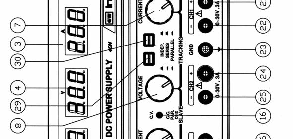
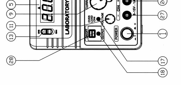
7 4. PANEL CONTROLS AND INDICATORS Fig. 4-2 Real Panel Fig. 4-1 Front Panel 6 7
8 4-1. Front Panel (1) Power switch : ON/OFF the power input. (2) Meter V : Indicated the CH1 or CH3 output voltage. (3) Meter A : Indicates the CH1 or CH3 output current. (4) Meter V : Indicates the CH2 or CH4 output voltage. (5) Meter A : Indicates the CH2 or CH4 output current. (6) Voltage Control : Adjust the output voltage of the CH1 supply, and as the adjustment control for the maximum output voltage of the CH2 supply when either parallel or series tracking operation. (7) Current Control : Adjust the output current of the CH1 supply, and as the adjustment control for the maximum output current of the CH2 supply when either parallel or series tracking operation. (8) Voltage Control : Adjust the output voltage of the CH2 supply when in independent operation. (9) (10) Voltage Control (11) Voltage Control (12) (13) Current Control CH1/CH3 selects switch CH2/CH4 selects switch : Adjust the output current of the CH2 supply. : Adjust the output voltage of the CH3 supply (invalid for GPS-2303&3303). : Adjust the output voltage of the CH4 supply (invalid for GPS-2303&3303). : Select CH1 or CH3 output voltage or current (invalid for GPS-2303&3303). : Select CH2 or CH4 output voltage or current (invalid for GPS-2303&3303). (14) Overload Indicator (15) CV&CC Indicator (16) CV&CC Indicator (17) Overload Indicator (18) Output Indicator (19) + output terminal (20) - output terminal (21) + output terminal (22) - output terminal (23) GND terminal (24) + output terminal (25) - output terminal (26) + output terminal (27) - output terminal : Lights when CH3 output load is larger than rating value (invalid for GPS-2303). : The CV light (green light) is on when the CH1 supply is in the constant voltage operation, or when both the CH1 and CH2 supplies are in the constant voltage operation in either series or parallel tracking mode. : The CC light (red light) is on when the CH1 supply is in the constant current operation. : The CV light (green light) is on when the CH2 supply is in the constant voltage operation. : The CC light (red light) is on when the CH2 supply is in the constant current operation or in parallel tracking mode. : Lights when CH4 output load is larger than rating value (invalid for GPS-2303&3303). : Switch the light on. : Positive polarity output terminal for the CH3 supply (invalid for GPS-2303). : Negative polarity output terminal for the CH3 supply (invalid for GPS-2303). : Positive polarity output terminal for the CH1 supply. : Negative polarity output terminal for the CH1 supply. : Earth and chassis ground. (28) Output switches : ON/OFF the output. : Positive polarity output terminal for the CH2 supply. : Negative polarity output terminal for the CH2 supply. : Positive polarity output terminal for the CH4 supply (invalid for GPS-2303&3303). : Negative polarity output terminal for the CH4 supply (invalid for GPS-2303&3303). 8 9
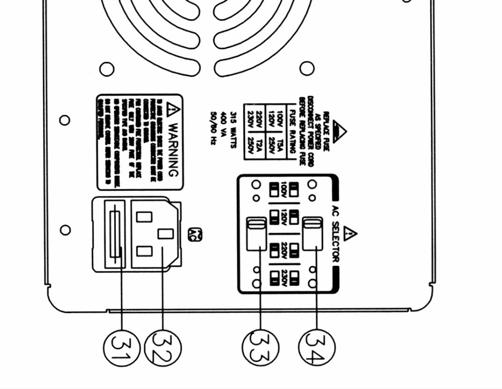
9 (29) TRACKING & Mode Switch (30) Two push-button switches that select Independent mode, series tracking mode, or parallel tracking mode as follows: a. When both switches are disengaged (out), the unit is in the Independent mode and the CH1 and CH2 power supplies are completely independent from each other. b. When the left switch is engaged (in) and the right switch is disengaged (out), the unit is in the Tracking series mode, maximum voltage of both supplies is set using the CH1 VOLTAGE controls (voltage at output terminals of the CH2 supply tracks the voltage at the output terminals of the CH1 SUPPLY). Also, in this mode of operation, the positive terminal (Red) of the CH2 supply is connected to the negative terminal (Black) of the CH1 supply to allow the two supplies to be used as a 0 to double rating voltage supply. c. When both switches are engaged (in), the unit is in the Tracking Parallel mode, the CH1 and CH2 supplies are wired together in parallel and both the maximum current and voltage are set using the CH1 controls. The CH1 and CH2 output can be used as two individual (but tracking) power supplies or just the CH1 output can be used as a 0 to rating voltage supply with a 0 to double rating current capability Real Panel (31) Fuse holder (32) Power socket (33) AC selects switch : Selects to permit operation from 100, 120, 220 or 230VAC, & 50/60Hz line voltage by using (34) HI-LO switch. (34) HI-LO switch : HI position selects high voltage range (120, 230V AC inputs), LO position selects low voltage range (100, 220V AC inputs). (35) Cooling Fan : Ventilates the hot air out, to prevent output stage from thermo shock, and improves the temperature coefficient. 5. OPERATION INSTRUCTION 5-1. Precaution (1) AC input AC input should be within the range of line voltage ± 10% (230V +10%~-6%) 50/60Hz. WANING. To avoid electrical shock, the power cord protective grounding conductor must be connected to ground. AVERTISS: Pour éviter les chocs électriques, le fil de terre du cordon secteur doit impérativement être relié à la terre. (2) Installation Avoid using the supply in a place where ambient temperature exceeds 40. The heat sink located at the rear of the supply must have sufficient air space for radiation. CAUTION. To avoid damaging the power supply, don t use it in a place where ambient temperature exceeds 40. (3) Output voltage overshoot Voltage between output terminals never exceeds the preset value when the power is turned on or off Setting Current Limit (1) Determine the maximum safe current for the device to be powered. (2) Temporarily short the (+) and (-) terminals of the power supply together with a test lead. (3) Rotate the VOLTAGE control away from zero sufficiently for the CC indicator to light. (4) Set the meter selection switch to A position to select the current metering mode. (5) Adjust the CURRENT control for the desired current limit. Read the current value on the Ammeter. (6) The current limit (overload protection) has now been preset. Do not change the CURRENT control setting after this step. (7) Remove the short between the (+) and (-) terminals and hook up for constant voltage 10 11

10 operation Constant Voltage/Constant Current Characteristics The working characteristic of these series Power Supplies is called a constant voltage/constant current automatic crossover type. This permits continuous transition from constant current to constant voltage modes in response to the load change. The intersection of constant voltage and constant current modes is called the crossover point. Fig. 5-1 shows the relationship between this crossover point and the load. For example, if the load is such that the power supply is operating in the constant voltage mode, a regulated output voltage is provided. The output voltage remains constant as the load increases, up until the point where the present current limit is reached. At that point, the output current becomes constant and the output voltage drops in proportion to further increases in load. The point is indicated by the front panel LED indicators. The crossover point is reached when the CV indicator goes off and the CC indicator comes on. Fig. 5-1 Constant Voltage/Constant Current Characteristic Similarly, crossover from the constant current to the constant voltage mode automatically occurs from a decrease in load. A good example of this would be seen when charging a 12 volt battery. Initially, the open circuit voltage of the power supply may be preset for 13.8 volts. A low battery will place a heavy load on the supply and it will operate in the constant current mode, which may be adjusted for a 1 amp charging rate. As the battery becomes charged, and its voltage approaches 13.8 volts, its load decreases to the point where it no longer demands the full 1 amp charging rate. This is the crossover point where the power supply goes into the constant voltage mode
11 5-4. Operation Mode (1) Independent Operation The CH1 and CH2 supplies each provide a 0 to rating volts output at up to rating amps. This procedure covers the use of the CH1 and CH2 supplies only when they are used independently from each other. When used in the independent operating mode, the operation controls of the two power supplies are completely independent and either supply can be used individually or both can be used simultaneously. A. Disengage both Tracking mode switches (both switches out) so that the power supply is in the independent operating mode. B. Adjust Voltage control and Current control to the desired output voltage and current. C. Turn off the power supply and the equipment to be powered during hook-up. D. Connect the positive polarity of the device being powered to the red (+) terminal of the power supply. E. Connect the negative polarity of the device being powered to the black (-) terminal of the power supply. F. Fig.5-2 illustrates the connection procedure. Power Supply Fig. 5-2 Independent Operation (2) Series Tracking Operation When the series tracking mode of operation is selected, the position (Red) terminal of the CH2 supply output is internally connected to the negative (black) terminal of the CH1 supply. In the series tracking mode, the maximum output voltage of both CH1 and CH2 supplies can be simultaneously varied with one control. The maximum CH2 supply voltage is automatically set to the same as the CH1 supply by using the CH1 VOLTAGE controls. A. Set the power supplies to the Tracking series mode by engaging the left Tracking switch and release the right Tracking switch. WARNING. Voltage more than 60V DC has a lethal shock hazard to the user. Be careful when connecting power supplies in series to achieve voltages higher than 60V DC total or 60V DC between any connection and earth ground. Note: Simultaneously metering of both current and voltage can be obtained in the mode of operation setting one of the displays for current metering and one for voltage metering. In this case, the output voltage (across the two supplies) is actually double the displayed value. For example, if the CH1 display is set for voltage metering and the CH2 display for current metering, the output voltage across the CH1 positive (red) terminal and the CH2 negative (black) terminal would be double the reading on the CH1 LED Display (since both supplies are putting out the same voltage). The actual output current would be the value read from the CH2 LED Display (since the two supplies are wired in series, current flowing through each supply must be equal). B. Set the CH2 CURRENT control to the full clockwise position. The maximum current is set by using the CH1 CURREN control. Follow the instructions for Setting current Limit (select CH1 or CH2 supply independently by using the CH1 CURRENT control). Note: Because the supplies are being used in series, either CURRENT control can be used to set maximum current. If desired, the CH1 CURRENT control can be rotated fully clockwise and the CH2 CURRENT control can be used to 14 15
12 adjust the maximum current value. Because current through the two supplies must be equal when they are being used in series, the lowest CURRENT control setting will set the maximum output current. C. Adjust the output voltage to the desired level by using the CH1 VOLTAGE controls. D. Turn off the power supply and the equipment to be powered during hook-up. E. If single supply operation is desired, this allows the power supply to be used as twice the voltage and rating current simply by using the negative (black) terminal of the CH2 supply and the positive (red) terminal of the CH1 supply, the configuration as shown in Fig Power Supply Fig. 5-3 Single Supply F. If the chassis or common of the equipment being powered is separated from both the positive and negative polarity power inputs, the output of the CH2 (negative) supply tracking the output of the CH1 (positive) supply, the configuration as shown in Fig (3) Parallel Tracking Operation In the parallel tracking mode of operation, both supplies are strapped together (in parallel). This allows for a rating voltage supply with a double rating current capability. Only the CH1 output terminals are used for parallel tracking operation. In the parallel tracking mode, the CH2 supply output voltage and current track the CH1 supply output voltage and current. A. Set the power supplies to the Tracking Parallel mode by engaging both Tracking switches. B. Output voltage will now be read from the CH1 VOLTAGE display. Output current is exactly double the value read from the CH1 CURRENT display (because each supply is providing the same amount of current). C.Because both voltage and current of the CH2 supply track the CH1 supply, the maximum current and voltage are set by using the CH1 controls. Using the CH1 supply output jacks, follow the instructions for Setting Current Limit (5-2 Section). Remember that the actual current output at the CH1 supply output jack is double the reading on the CH2 indicator meter. D.Adjust the output voltage to the desired level by using the CH1 VOLTAGE controls. E. Turn off the power supply and the equipment to be powered during hook-up. F. Connect the positive polarity of the device being powered to the red (+) terminal of the CH1 power supply. G. Connect the negative polarity of the device being powered to the black (-) terminal of the CH1 power supply. The configuration is shown as Fig. 5-5: Power Supply Power Supply Fig. 5-4 Positive and Negative Supply Fig. 5-5 Parallel Tracking Operation 16 17
13 (4) CH3 Power Supply Operation The CH3 supply provides 2.2~5.2V(GPS-4302/4303) and 3~6V(GPS-4251) DC output with 3 amps (GPS-3303&4302), 1 amp (GPS-4303) and 2.5 amp (GPS-4251) current capacity. The supply is ideal for us with TTL circuits (GPS V Fixed). A. Turn off the power supply and the equipment to be powered during hook-up. B. Connect the positive polarity of the device being powered to the red (+) terminal of the CH3 supply. C. Connect the negative polarity of the device being powered to the black (-) terminal of the CH3 supply. D. If the red OVERLOAD indicator lights, means exceeding load has been placed on the supply, it will cause voltage and current to drop and interfere the proper operation of the CH3 supply. To correct this situation, the load on the supply must be decreased so that no more than 3 amps (GPS-3303&4302), 1amp (GPS-4303) and 2.5 amps (GPS-4251) of current are required. (5) CH4 Power Supply Operation The CH4 supply provides a 8~15V(GPS-4302/4303/4251) DC output with a 1 amps current capacity. A.Turn off the power supply and the equipment to be powered during hook-up. B. Connect the positive polarity of the device being powered to the red (+) terminal of the CH4 supply. C. Connect the negative polarity of the device being powered to the black (-) terminal of the CH4 supply. D. If the red OVERLOAD indicator lights, exceeding load has been placed on the supply, it will cause voltage and current to drop and interfere proper operation of the CH4 supply. Under this situation, the load on the supply must be decreased so that no more than 1 amp of current is required. (6) Dynamic Load Operation & Application A. When select to dynamic load position, the max peak current is at 1.7 times rating current. The features are only applied for audio circuit of amplifier and audio production lines. Change the position of wafer J111 of CH1 and J309 of CH2 from OFF to ON. Please refer to Fig.6-1 Adjustment Location. B. For other application and testing (Safety or CE. etc.), must set the wafer at OFF position (7) Output ON/OFF Action The output ON/OFF action is controlled with a single control, the output switch is pushed on, a high single output is on and output LED is on, while the output switch is pushed off, or tracking switch is pressed, output will disable. CAUTION: The output terminals are for use only with the equipment which has no accessible live parts. The output terminals should not be connected to any hazardous live parts. (8) Fan Control 1) The fan of the power supply will not work upon power on until the temperature of the heat sink rises up to 32 ±5 after adding load to output terminal. The more the temperature of the heat sink rises, the more the rolling speed of the fan gets fast. The fastest rolling speed is when the temperature reaches to 70. 2) To avoid damaging the power supply, if the fan fails to work when the temperature reached to the appropriate value, turn off the instrument and check the cause
14 6. MAINTENANCE WARNING The following instructions are for use by qualified personnel only. To avoid electrical shock, do no perform any servicing other than the operation instruction of the manual unless you are qualified to do so Fuse Replacement If the fuse blows, the CV or CC indicators will not light and the power supply will not operate. The fuse should not normally open unless a problem has developed in the unit. Try to determine and correct the cause of the blown fuse, then replace only with a fuse of the correct rating and type. The fuse is located on the rear panel (see Fig.4-2 & Table 2-1). WARNING: For continued fire protection, replace fuse only with 250V fuse of the specified type and rating, and disconnect power cord before replacing fuse. AVERTISS: Pour une protection contre les risques d incendie, remplacer le fusible exclusivement par un modèle aux caractéristiques équivalentes Line Voltage Conversion The primary winding of the power transformer is tapped to permit operation from 100, 120, 220, or 230VAC, 50/60Hz line voltage. Conversion from one line voltage to another is done by change AC selects switch as shown in Fig The rear panel identifies the line voltage to which the unit was factory set. To convert to a different line voltage, perform the following procedure: (1) Make sure the power cord is unplugged. (2) Change the AC selects switch to the desired line voltage position. (3) A change in line voltage may also require a corresponding change of fuse value. Install the correct fuse value as listed on rear panel Adjustments This unit was accurately adjusted at the factory before shipment. Readjustment is recommended only if repairs have been made in a circuit affecting adjustment accuracy or if you have a reason to believe the unit is out of adjustment. The recommended calibration device is a multimeter with an accuracy of ±0.1% DCV or better (GOOD WILL model GDM-8145 or equivalent). If readjustment is required, use the following procedure. The location of the adjustments is shown in Fig (1) Independent Adjustment A. Disengage both Tracking mode switches (both switches out) so that the power supply is in the independent operating mode. B. Connect a 4-1/2 digital multimeter with an accuracy of ±0.1% DCV to measure the DC voltage at the output terminals of the CH1 (CH2) supply. C. Set the CH1 (CH2) VOLTAGE control to maximum (fully clockwise). D. Adjust trimmer potentiometer (VR101 CH1,VR301 CH2) on the circuit board (located on the right side of the supply) for a reading as close to rating voltage 1.05 (on the multimeter) as possible. E. Set output on by adjusting the trimmer potentiometer (VR801 CH2, VR201 CH1) from the CH1 (CH2) voltage indicator circuit board (located on the meter or A/D converter board) for a reading of rate voltage 1.05 on the CH1 (CH2). F. Set output off by adjusting trimmer potentiometer (VR802 CH2, VR202 CH1) from the CH1 (CH2) voltage indicator circuit board (located on the meter or A/D converter board) for a reading of rate voltage on the CH1 (CH2)(invalid for GPS-2303) G. Connect the external multimeter across the CH1 (CH2) SUPPLY output terminals to read the output current (so that the meter causes a short circuit across the terminals) and adjust the CH1 (CH2) CURRENT control so that rating amps is read on the multimeter. H. Set output on by adjusting the trimmer potentiometer (VR901 CH2, VR701 CH1) so that the CH1(CH2) meter also reads rating amps. I. Rotate the CH1(CH2) current control fully clockwise (maximum). J. Adjust VR103 on the CH1 (VR303 CH2)supply circuit board (located on the right side of the supply) to obtain an output current of rating amps 1.05 (read on the meter or LED display)
15 K. Set output off by adjusting the trimmer potentiometer (VR903 CH2, VR703 CH1) so that the CH1(CH2) meter also reads rating amps (invalid for GPS-2303). (2) Series Tracking Adjustment A. Set the supply to Tracking series mode by engaging the left Tracking switch and releasing the right tracking switch. B. Set the CH2 CURRENT control to midrange and set the CH1 supply voltage controls to minimum (fully counterclockwise). C. Connect the multimeter to the CH1 SUPPLY outputs and measure the voltage. D. Disconnect the multimeter from the CH1 supply outputs and connect it across the CH2 supply outputs. E. Adjust trimmer potentiometer VR306 on the circuit board (located on the right side of the supply) to obtain the exact same reading for the CH2 supply output as was preset at the CH1 supply output (e.g., if the minimum CH1 supply output voltage is 10.00mV adjust VR306 to obtain an output voltage as close to mV at the CH2 supply as possible). F. Set the CH2 CURRENT control to midrange and set the CH1 supply voltage controls to maximum (fully clockwise). G. Connect the multimeter to the CH1supply outputs and measure the voltage. H. Disconnect the multimeter from the CH1supply outputs and connect it across the CH2 supply outputs. I. Set output on by adjusting VR501 (located at the left of the lower front panel circuit board, VOLTAGE/CURRENT CONTROL potentiometer board) until the voltage read from the multimeter is the same as it was across the CH1 output terminals. Return the multimeter to the CH1 output terminals and verify that the output voltage is identical. If not, repeat this step. J. Set output off by adjusting VR804 (located at the left of the lower front panel circuit board, VOLTAGE/CURRENT CONTROL potentiometer board) until the voltage read from the multimeter is the same as it was across the CH1 output terminals. Return the multimeter to the CH1 output terminals and verify that the output voltage is identical. If not, repeat this step (invalid for GPS-2303). (3) Parallel Tracking Adjustment A. Disengage both Tracking mode switches (both switches out) so that the power supply is in the independent operating mode. B. Set the CH1 supply VOLTAGE and CURRENT controls to minimum (fully counterclockwise). C. Connect the multimeter across the CH1 supply output terminals and measure the output current. D. Set the CH1 supply VOLTAGE control to midrange and adjust the CURRENT control to obtain an output current of rating amps (read on the multimeter). Do not change the CURRENT control setting after this step. E. Engaged both Tracking mode switches (both switches in), so that the power supply is in the parallel operating mode. F. Set the CH2 supply CURRENT control to maximum (fully clockwise) and set the VOLTAGE control to midrange. G. Set output on by adjusting the trimmer potentiometer VR502 on the circuit board (located on the right side of the supply) to obtain an output current of double rating amps on the multimeter. (4) CH3 Supply Adjustment A. Connect the multimeter across the output terminals of the CH3 supply to read output voltage and adjust the VR403 to obtain reading of 2.2~5.2V(GPS-4302/4303), 3~6V(GPS-4251) and fixed 5V(GPS-3303) on the multimeter. B. Set the supply VOLTAGE control to maximum (fully clockwise), set output off by adjusting trimmer potentiometer VR203 on the CH3 voltage indicator circuit board (located on the meter or A/D converter board) for a reading of rate voltage on the CH3 (invalid for GPS-3303). C. Turn VR401 on the main master circuit board (located on the right side of the supply) fully counterclockwise
16 D. Set output on by adjusting VR702 so that the CH3 meter also reads rating amps (invalid for GPS-3303). E. Connect a variable load (load must be rated to handle a power of at least 30W) across the output terminals and connect the multimeter to read the output current, then adjust the load on the multimeter to show an output current at 3.25A for GPS-3303&4302, 1.20A for GPS-4303 and 2.75A for GPS F. Slowly adjust VR402 clockwise until the output voltage (read from the multimeter) drops 5mV to 6mV (start current limit point). G. Connect a variable load across the output terminals and connect the multimeter to read the output current, then adjust the load on the multimeter to show an output current at 3.15A for GPS-3303&4302, 1.10A for GPS-4303, and 2.65A for GPS H. Adjust VR402 until the 3A (GPS-3303&4302), 2.5A(GPS-4251) and 1A (GPS-4303) OVERLOAD indicator light. (5) CH4 Supply Adjustment A. Connect the multimeter across the output terminals of the CH4 SUPPLY to read output voltage and adjust VR603 to obtain a reading of 8~15V(GPS-4302/4303/4251) on the multimeter. B. Set the supply VOLTAGE control to maximum (fully clockwise), set output off by adjusting the trimmer potentiometer VR803 from the CH4 voltage indicator circuit board (located on the meter or A/D converter board) for a reading of rate voltage on the CH4. C. Turn VR601 on the main master circuit board (located on the right side of the supply) fully counterclockwise. D. Set output on by adjusting VR902 so that the CH4 meter also reads rating amps. E. Connect a variable load (load must be rated to handle a power of at least 30W) across the output terminals and connect the multimeter to read the output current, then adjust the load on the multimeter to show an output current at 1.20A. F. Slowly adjust VR602 clockwise until the output voltage (read from the multimeter) drops to 5mV~6mV (start current limit point). G. Connect a variable load across the output terminals and connect the multimeter to read the output current, then adjust the load on the multimeter to show an output current at 1.10A. H. Adjust VR602 until the 1.10A OVERLOAD indicator first lights Cleaning To clean the power supply, use a soft cloth dampened in a solution of mild detergent and water. Do not spray cleaner directly onto the instrument, since it may leak into the cabinet and cause damage. Do not use chemicals containing benzine, benzene, toluene, xylene, acetone, or similar solvents. Do not use abrasive cleaners on any portion of the instrument
17 Fig Adjustment Location 26
DC POWER SUPPLY ALIMENTATION C.C.
 DC POWER SUPPLY ALIMENTATION C.C. ISO-TECH IPS 303A 201-3424 ISO-TECH IPS 601A 201-3446 SAFETY TERMS AND SYMBOLS These terms may appear in this manual or on the product: WARNING. Warning statements identify
Declaration of Conformity
 We Declaration of Conformity GOOD WILL INSTRUMENT CO., LTD. No. 7-1, Jhongsing Rd, Tucheng City, Taipei County 236, Taiwan GOOD WILL INSTRUMENT (SUZHOU) CO., LTD. No.69 Lushan Road, Suzhou New District
BENCHTOP INSTRUMENT. Multi-channel DC Power Supply TP2000N/TP2000PU/TP4000N Series Operation Manual V1.0
 BENCHTOP INSTRUMENT Multi-channel DC Power Supply TP2000N/TP2000PU/TP4000N Series Operation Manual V1.0 CONTENTS 1. INTRODUCTION... - 1-2. PRODUCTION MODELS... - 2-3. SPECIFICATIONS... - 3-4. PANEL CONTROLS
DC POWER SUPPLY (Switching mode)
") DC POWER SUPPLY (Switching mode) ISO-TECH IPS1820D RS Stock No. 357-0760 ISO-TECH IPS3610D RS Stock No. 357-0776 ISO-TECH IPS606D RS Stock No. 357-0782 82IP-3610DMB Ei SAFETY TERMS AND SYMBOLS These terms
DC POWER SUPPLY (Switching mode) ISO-TECH IPS1820D RS Stock No. 357-0760 ISO-TECH IPS3610D RS Stock No. 357-0776 ISO-TECH IPS606D RS Stock No. 357-0782 82IP-3610DMB Ei SAFETY TERMS AND SYMBOLS These terms
ISO-TECH IPS1810H and IPS1603D DC power supply ISO-TECH IPS 1810H et IPS 1603D Alimentation électrique c.c.
 ISO-TECH IPS1810H and IPS1603D DC power supply ISO-TECH IPS 1810H et IPS 1603D Alimentation électrique c.c. ISO-TECH IPS 1810H 204-713 ISO-TECH IPS 1603D 204-729 82IP-1810HME Ei Statement of Compliance
SAFETY TERMS AND SYMBOLS
 SAFETY TERMS AND SYMBOLS These terms may appear in this manual or on the product: WARNING. Warning statements identify condition or practices that could result in injury or loss of life. CAUTION. Caution
BENCHTOP INSTRUMENT. Single Channel DC Power Supply SL Series Operation Manual V1.0
 BENCHTOP INSTRUMENT Single Channel DC Power Supply SL Series Operation Manual V1.0 CONTENTS 1. INTRODUCTION... - 1-2. PRODUCTION MODELS... - 1-3. SPECIFICATIONS... - 2-4. PANEL CONTROLS AND INDICATORS...
DC POWER SUPPLY GPS-S SERIES (ANALOG 1 DIGITAL TYPE) User Manual ISO-9001 CER TIFIED MANUFACTURER
 User Manual ISO-9001 CER TIFIED MANUFACTURER") DC POWER SUPPLY GPS-S SERES (ANALOG 1 DGTAL TYPE) User Manual SO-9001 CER TFED MANUFACTURER SECTON CONTENTS PAGE 1 NTRODUCTON... 1 2. SPECFCATONS... 2 2- General... 2 2-2 Constant Voltage Operation...
DC POWER SUPPLY GPS-S SERES (ANALOG 1 DGTAL TYPE) User Manual SO-9001 CER TFED MANUFACTURER SECTON CONTENTS PAGE 1 NTRODUCTON... 1 2. SPECFCATONS... 2 2- General... 2 2-2 Constant Voltage Operation...
Triple Output Power Supply
 Test Equipment Depot - 800.517.8431-99 Washington Street Melrose, MA 02176 TestEquipmentDepot.com Model 1672, 1673 Triple Output Power Supply INSTRUCTION MANUAL 1 Safety Summary The following safety precautions
WARNING MANUFACTURER ASSUMES NO LIABILITY IF UNIT OPERATED IN AN UNSAFE MANNER.
 WARNING MANUFACTURER ASSUMES NO LIABILITY IF UNIT OPERATED IN AN UNSAFE MANNER. WARNING THIS INSTRUMENT GENERATES AND DELIVERS A HAZARDOUSLY HIGH VOLTAGE (5kV). BE EXTREMELY CAREFUL WHEN USING THIS INSTRUMENT.
90W DC Power Supply. User Manual. 99 Washington Street Melrose, MA Phone Toll Free
 99 Washington Street Melrose, MA 02176 Phone 781-665-1400 Toll Free 1-800-517-8431 Visit us at www.testequipmentdepot.com 1410 90W DC Power Supply User Manual Safety Summary The following safety precautions
Model 1672, 1673 Triple Output Power Supply
 Model 1672, 1673 Triple Output Power Supply INSTRUCTION MANUAL 1 Safety Summary The following safety precautions apply to both operating and maintenance personnel and must be observed during all phases
& HIGH CURRENT DC POWER SUPPLIES INSTRUCTION MANUAL
 72-6850 & 72-6852 HIGH CURRENT DC POWER SUPPLIES INSTRUCTION MANUAL Table of Contents Introduction 2 Specification 2 Safety 4 EMC 5 Installation 6 Connections 6 Operation 7 Maintenance and Repair 8 www.tenma.com
DC REGULATED POWER SUPPLY
 INSTRUCTION MANUAL Models 1620A/ 1621A/ 1622A/ 1623A/ 1626A/ 1627A DC REGULATED POWER SUPPLY Test Equipment Depot - 800.517.8431-99 Washington Street Melrose, MA 02176 TestEquipmentDepot.com TABLE OF CONTENTS
INSTRUCTION MANUAL Model 1743B
 Test Equipment Depot - 800.517.8431-99 Washington Street Melrose, MA 02176 TestEquipmentDepot.com INSTRUCTION MANUAL Model 1743B 0-35 V, 0-6 A DC POWER SUPPLY With Dual 4-Digit LED Displays TEST INSTRUMENT
Triple Output High Resolution Power Supply. User Manual
 1320 Triple Output High Resolution Power Supply User Manual Safety Summary The following safety precautions apply to both operating and maintenance personnel and must be observed during all phases of operation,
DC REGULATED POWER SUPPLY
 INSTRUCTION MANUAL Models 1620A/ 1621A/ 1622A/ 1623A/ 1626A/ 1627A MANUAL DE INSTRUCCIONES DC REGULATED POWER SUPPLY TABLE OF CONTENTS 1. INTRODUCTION... 3 2. FEATURES... 3 3. SPECIFICATIONS... 4 4. PRCAUTIONS
Switching DC Power Supply
 99 Washington Street Melrose, MA 02176 Phone 781-665-1400 Toll Free 1-800-517-8431 Visit us at www.testequipmentdepot.com Model 1693, 1694 Switching DC Power Supply INSTRUCTION MANUAL 1 Safety Summary
DUAL 60V 20A POWER FLEX POWER SUPPLY INSTRUCTION MANUAL
 72-7570 DUAL 60V 20A POWER FLEX POWER SUPPLY INSTRUCTION MANUAL Table of Contents Specification 1 Safety 3 EMC 4 Installation 5 Connections 5 Operation 6 Maintenance 8 Specification General specifications
99 Washington Street Melrose, MA Fax TestEquipmentDepot.com. Instruction Manual. Model 1672 Triple Output Power Supply
 99 Washington Street Melrose, MA 02176 Fax 781-665-0780 TestEquipmentDepot.com Instruction Manual Model 1672 Triple Output Power Supply Contents Section Description Page No. CONTENTS 1 1 TEST INSTRUMENT
LAVOLTA DC REGULATED POWER SUPPLY BPS-305
 LAVOLTA DC REGULATED POWER SUPPLY BPS-305 USER MANUAL 1 In order to use the power supply better, please read the user manual carefully before using and keeping it properly. Warning: Do not connect any
HT3003PB HT3005PB MULTI-OUTPUT DC REGULATED POWER SUPPLY
 HT3003PB HT3005PB MULTI-OUTPUT DC REGULATED POWER SUPPLY This series include two-way and three-way DC regulated power supply. Three-way have high accuracy output of which two way are adjustable and one
SSP-7080 USER MANUAL. 80W Constant Power Switching Mode Power Supply with Master & Slave Remote Sensing. Rev /
 SSP-7080 80W Constant Power Switching Mode Power Supply with Master & Slave Remote Sensing USER MANUAL Rev.1.1 2007/04 7673-7080-0000 CONTENTS Warning, Cautions and Operating Conditions P.1 Introduction
Safety Precautions. Damages resulting from failure to observe these safety precautions are exempt from any legal claims whatever.
 Safety Precautions This product complies with the requirements of the following European Community Directives: 2004/108/EC (Electromagnetic Compatibility) and 2006/95/EC (Low Voltage) as amended by 2004/22/EC
Variable Regulated Voltage Power Supply Instruction Manual Model XP-605 / XP-752A
 Variable Regulated Voltage Power Supply Instruction Manual Model XP-605 / XP-752A Copyright Elenco Electronics, Inc. REV-D DC POWER SUPPLY 1 2 4 5 CURRENT VOLTAGE 13 3 6 C.C. C.V. 7 FINE COARSE FINE COARSE
EPS/ELA-Series User Manual EPS/ELA 250W
 EPS/ELA-Series User Manual EPS/ELA 250W EPS Stromversorgung GmbH Tel: +49 (0)821 570451 0 Index 3 Page: 1 Table of contents: Page 1. Features of ELA-Series... 3 1.1 Basic Functions... 3 1.2 Options...
3000 Series Operation Manual
 Operation Manual Copyright Copyright 1995 by this company. All rights reserved. No part of this publication may be reproduced in any form or by any means without the written permission of this company.
99 Washington Street Melrose, MA Fax TestEquipmentDepot.com. Instruction Manual. Model 2831D 4 ½ Digit True RMS Digital Multimeter
 99 Washington Street Melrose, MA 02176 Fax 781-665-0780 TestEquipmentDepot.com Instruction Manual Model 2831D 4 ½ Digit True RMS Digital Multimeter 1 1. PRODUCT DESCRIPTION 1-1. Introduction Thank you
Sorensen XG 1700 Series 1700 W A Watt, 1U Programmable DC Power Supplies V. Key Features. Key Modes
 Sorensen XG 1700 Series 1700 W 1700 Watt, 1U Programmable DC Power Supplies 6 600 V Industry Leading Power Density Up to 1700 Watts in 1U Standard Digital Interfaces USB&RS232/485 LXI Ethernet and Isolated
1. SAFETY TERMS AND SYMBOLS. Contents. 1. Safety terms and symbols Installation Operation.. 4
 Contents 1. Safety terms and symbols.. 1 2. Installation... 2 3. Operation.. 4 4. Panel Description.. 8 5. Calibration... 11 6. Circuit Principle 14 7 Block Diagram... 15 8. Specification 16 9. Maintenance
RS-3 PRO RS-1007 PRO. CAT IV Analog Clamp meter Series. Users Manual. For detailed specifications and ordering info go to
 RS-3 PRO RS-1007 PRO CAT IV Analog Clamp meter Series Users Manual For detailed specifications and ordering info go to www.testequipmentdepot.com RS-3 PRO RS-1007 PRO CAT IV Analog Clampmeter Series English
MY /2-DIGIT DIGITAL MULTIMETER Users Manual
 MY-65 4 1/2-DIGIT DIGITAL MULTIMETER Users Manual Read the Users Manual thoroughly before use. WARRANTY This instrument is warranted to be free from defects in material and workmanship for a period of
MPS14 Rack Mount Power Supply
 MPS14 Rack Mount Power Supply USER GUIDE Publication AP3898 Limited One Year Warranty This product has been manufactured in the UK by ALLEN & HEATH and is warranted to be free from defects in materials
Sorensen XG Series / XTR Series W A. 850 W, 1U Half Rack Programmable DC Power Supplies V
 Sorensen XG Series / XTR Series 670 850 W 850 W, 1U Half Rack Programmable DC Power Supplies 6 600 V Highest Power Density Comprehensive Digital and Analog Interface Options Scalable, Multi-Unit Design
ALR output Powerfull PROGRAMMABLE POWER SUPPLY 640 WATTS 0-32V 0-20A POWERFUL. Specifications
 $ PROGRAMMABLE POWER SUPPLY EAN CODE : 3760244880062 1 output Powerfull POWERFUL ALR3220 VISUAL : Large graphic display SOFT-TOUCH : Sensitiv keypad CONNECTED : USB, RS232, RS485 & 0-10V isolated LabVIEW
Autoranging Industrial Multimeter
 Owner's Manual Autoranging Industrial Multimeter Model No. 82005 CAUTION: Read, understand and follow Safety Rules and Operating Instructions in this manual before using this product. Safety Operation
MOdel No: MM19.V3 WARNING CAUTION 1. SAFETY INSTRUCTIONS
 Instructions for: Digital Multimeter - 6 Function MOdel No: MM19.V3 Thank you for purchasing a Sealey product. Manufactured to a high standard this product will, if used according to these instructions
Mini Multimeter with Non-Contact Voltage Detector (NCV)
") Owner s Manual Mini Multimeter with Non-Contact Voltage Detector (NCV) Model No. 82314 CAUTION: Read, understand and follow Safety Rules and Operating Instructions in this manual before using this product.
Owner s Manual Mini Multimeter with Non-Contact Voltage Detector (NCV) Model No. 82314 CAUTION: Read, understand and follow Safety Rules and Operating Instructions in this manual before using this product.
Digital Multimeter User's Manual
 Digital Multimeter User's Manual MS8239A MS8239A DIGITAL MULTIMETER Auto Power Off V HOLD 600 600 20 10A A m 10A 20m 2 m V MAX 10A/ 500V COM 600V CAT III IEC61010-1 12V 9V BATT. k 2M 600V MAX MAX ma/250v
CIRCUIT-TEST OPERATION MANUAL. Switching Mode Power Supply with Remote Sensing PSC V 5A / 0-27V 3A / 0-36V 2.2A (80W)
") CIRCUIT-TEST Switching Mode Power Supply with Remote Sensing PSC-9800 0-16V 5A / 0-27V 3A / 0-36V 2.2A (80W) OPERATION MANUAL 1 2 PSC-9800 08R14 Contents Safety Precautions...page 4 Introduction... 5 Controls
CIRCUIT-TEST Switching Mode Power Supply with Remote Sensing PSC-9800 0-16V 5A / 0-27V 3A / 0-36V 2.2A (80W) OPERATION MANUAL 1 2 PSC-9800 08R14 Contents Safety Precautions...page 4 Introduction... 5 Controls
MM300. INSTRUCTION MANUAL Manual-Ranging Digital Multimeter
 INSTRUCTION MANUAL Manual-Ranging Digital Multimeter MM300 DATA HOLD AUDIBLE CONTINUITY BATTERY TEST DIODE TEST 10A 2MΩ ESPAÑOL pg. 13 FRANÇAIS pg. 25 MM300-1390109ART.indd 1 9/21/2015 2:48:00 PM GENERAL
Model 1693, 1694 Switching DC Power Supply
 Model 1693, 1694 Switching DC Power Supply INSTRUCTION MANUAL 1 Safety Summary The following safety precautions apply to both operating and maintenance personnel and must be observed during all phases
LEAD ACID BATTERY CHARGER
 LEAD ACID BATTERY CHARGER MODEL NO: LA4 & LA6 OPERATION & MAINTENANCE INSTRUCTIONS LS1214 INTRODUCTION Thank you for purchasing this CLARKE Battery Charger. Please read this manual thoroughly, before attempting
Matrix APAX. 380V-415V 50Hz TECHNICAL REFERENCE MANUAL
 Matrix APAX 380V-415V 50Hz TECHNICAL REFERENCE MANUAL WARNING High Voltage! Only a qualified electrician can carry out the electrical installation of this filter. Quick Reference ❶ Performance Data Pages
Power thyristor units. 460 series. Control of single-phase resistive and inductive loads. User Manual
 Power thyristor units 460 series Control of single-phase resistive and inductive loads User Manual Copyright Eurotherm Automation 1996 All rights reserved. All reproduction or transmission in any form
BATTERY STARTER/CHARGER MODEL NO: BC125, BC190
 BATTERY STARTER/CHARGER MODEL NO: BC125, BC190 PART NO: 6210125, 6210200 OPERATION & MAINTENANCE INSTRUCTIONS LS0616 INTRODUCTION Thank you for purchasing this CLARKE Battery starter / charger Please read
User's Manual. High Voltage Megohmmeter. Analog Insulation Tester plus AC Voltage and Continuity Tests. Model
 User's Manual High Voltage Megohmmeter Analog Insulation Tester plus AC Voltage and Continuity Tests Model 380353 Warranty EXTECH INSTRUMENTS CORPORATION warrants this instrument to be free of defects
Maintenance Manual 13 AMPERE POWER SUPPLY 19A704647P1-P3. Mobile Communications LBI-31801C
 C Mobile Communications 13 AMPERE POWER SUPPLY 19A704647P1-P3 CAUTION THESE SERVICING INSTRUCTIONS ARE FOR USE BY QUALI- FIED PERSONNEL ONLY. TO AVOID ELECTRIC SHOCK DO NOT PERFORM ANY SERVICING OTHER
USER MANUAL GEBRUIKSAANWIJZING GEBRAUCHSANWEISUNG SKYLLA 24/100 3-PHASE CE
 USER MANUAL GEBRUIKSAANWIJZING GEBRAUCHSANWEISUNG SKYLLA 24/100 3-PHASE CE SECTIONS: ENGLISH 2 NEDERLANDS 17 DEUTSCH 37 Victron Energy BV De Paal 35 1351 JG Almere-Haven The Netherlands Article number
PRM-4. Phase Sequence and Motor Rotation Tester. Users Manual. For detailed specifications and ordering info go to
 PRM-4 Phase Sequence and Motor Rotation Tester Users Manual For detailed specifications and ordering info go to www.testequipmentdepot.com PRM-4 Phase Sequence and Motor Rotation Tester English Users Manual
RE-PR3-E-86&105 3-Phase Panel Mount 86 and 105kW
 Page 1 of 6 3-Phase Panel Mount 86 and 105kW Features: Benefits: 0-10Vdc, 0-5Vdc, 4-20mA or manual via potentiometer control input Over temperature protection with auto reset Enclosed panel mounting Efficient
RVS-AX Instruction Manual
 RVS-AX Analog Soft Starter 8-170A, 220-600V Instruction Manual Ver. 10/11/2009 2 Table of Content RVS-AX Instruction Manual 1. TABLE OF CONTENT 1. Table of Content...2 2. Safety & Warnings...3 2.1 Safety...3
Model 1900, 1901, 1902 Switching DC Power Supply
 Model 1900, 1901, 1902 Switching DC Power Supply INSTRUCTION MANUAL 1 Safety Summary The following safety precautions apply to both operating and maintenance personnel and must be observed during all
Low Amp Probe EETA308A
 Low Amp Probe EETA308A Reference Manual First Edition SAFETY WARNING DO NOT APPLY OVER 150V AC (RMS) OR DC. DISCONNECT LEADS BEFORE REMOVING THE BATTERY COVER. DO NOT ALLOW THE CABLE TO BECOME ENTANGLED
HEAVY DUTY BATTERY BOOSTERS / CHARGERS. MODEL Nos. BC185N & BC205N OPERATING INSTRUCTIONS
 HEAVY DUTY BATTERY BOOSTERS / CHARGERS MODEL Nos. BC185N & BC205N OPERATING INSTRUCTIONS 0614 Thank you for purchasing this CLARKE Battery Charger. These units are suitable for charging and boosting 12
POWER SUPPLY MODEL XP-800. TWO AC VARIABLE VOLTAGES; 0-120V and 7A, PLUS UP TO 10A. Instruction Manual. Elenco Electronics, Inc.
 POWER SUPPLY MODEL XP-800 TWO AC VARIABLE VOLTAGES; 0-120V and 0-40V @ 7A, PLUS 0-28VDC @ UP TO 10A Instruction Manual Elenco Electronics, Inc. Copyright 1991 Elenco Electronics, Inc. Revised 2002 REV-I
Contents. Introduction Inspection Notes on Safety Precautions. Chapter 1 Overview Product Overview Names of Parts 2
 INSTRUCTION MANUAL Contents Introduction Inspection Notes on Safety Precautions i i ii vii Chapter 1 Overview 1 1.1 Product Overview 1 1.2 Names of Parts 2 Chapter 2 Specifications 5 2.1 Product Specifications
True RMS Autoranging Multimeter
 Owner's Manual True RMS Autoranging Multimeter Model No. 73754 CAUTION: Read, understand and follow Safety Rules and Operating Instructions in this manual before using this product. Safety Operation Maintenance
BATTERY BOOSTER/CHARGER MODEL NO: DIGICAR 600
 BATTERY BOOSTER/CHARGER MODEL NO: DIGICAR 600 PART NO: 6261200 OPERATION & MAINTENANCE INSTRUCTIONS LS0815 INTRODUCTION Thank you for purchasing this CLARKE Battery booster / charger which is suitable
DRB-1 Series Instruction Manual
 Instruction Manual BEFORE USING THE POWER SUPPLY UNIT Pay attention to all warnings and cautions before using the unit. Incorrect usage could lead to an electrical shock, damage to the unit or a fire hazard.
APEX DRIVE USER GUIDE ADDENDUM: LVD INSTALLATION INSTRUCTIONS
 APEX DRIVE USER GUIDE ADDENDUM: LVD INSTALLATION INSTRUCTIONS Product Type: APEX10, APEX20 and APEX40 Servo Drives The above products are in compliance with the requirements of directives 72/23/EEC Low
Autoranging Multimeter
 Owner's Manual Autoranging Multimeter Model No. 82334 CAUTION: Read, understand and follow Safety Rules and Operating Instructions in this manual before using this product. Safety Operation Maintenance
HEAVY DUTY BATTERY BOOSTERS / CHARGERS. MODEL Nos. BC260N & BC335 OPERATING & MAINTENANCE INSTRUCTIONS
 HEAVY DUTY BATTERY BOOSTERS / CHARGERS MODEL Nos. BC260N & BC335 OPERATING & MAINTENANCE INSTRUCTIONS 0707 Thank you for purchasing this CLARKE Battery Charger. These units are suitable for charging and
Mini Multimeter with Non-Contact Voltage Detector (NCV)
") Owner s Manual Mini Multimeter with Non-Contact Voltage Detector (NCV) Model No. 82315 REL CAUTION: Read, understand and follow Safety Rules and Operating Instructions in this manual before using this
Owner s Manual Mini Multimeter with Non-Contact Voltage Detector (NCV) Model No. 82315 REL CAUTION: Read, understand and follow Safety Rules and Operating Instructions in this manual before using this
BATTERY BOOSTER/CHARGER MODEL NO: DIGICAR 900
 BATTERY BOOSTER/CHARGER MODEL NO: DIGICAR 900 PART NO: 6261205 OPERATION & MAINTENANCE INSTRUCTIONS LS0715 INTRODUCTION Thank you for purchasing this CLARKE Battery booster / charger which is suitable
Document: PRODSPEC-140 Revision: G DCN No Date: October 1, 2014 Product: 10-amp EnerGenius NRG Battery Charger
 Document: PRODSPEC-140 Revision: G DCN No. 106512 Date: October 1, 2014 Product: 10-amp EnerGenius NRG Battery Charger 1. GENERAL DESCRIPTION 1.1 General Description Fully regulated, constant voltage,
OPERATING INSTRUCTIONS
 CM OPERATING INSTRUCTIONS 9 Function, Auto Range Digital Multi-Meter DM6450 INTERTEK Read this owner s manual thoroughly before use and save. C LISTED US I. DISPLAY FUNCTIONS & SYMBOLS 9 6 10 11 14 8 7
LH41A. User Manual. Clamp On Ammeter. For detailed specifications and ordering info go to
 LH41A Clamp On Ammeter User Manual For detailed specifications and ordering info go to www.testequipmentdepot.com LH41A Clamp On Ammeter Users Manual English April 2007, Rev.2 2007 Amprobe Test Tools.
Chargestar P24 / P32 Battery Charger Startmaster P300 Starter / Charger
 Please dispose of packaging for the product in a responsible manner. It is suitable for recycling. Help to protect the environment, take the packaging to the local amenity tip and place into the appropriate
User s Manual Power Supply. IM E 3rd Edition. Yokogawa Electric Corporation
 User s Manual 700938 Power Supply Yokogawa Electric Corporation 3rd Edition Introduction Revisions Thank you for purchasing the 700938 Power Supply. This Instruction Manual contains useful information
LS200 Series Instruction Manual
 LS200 Series Instruction Manual BEFORE USING THE POWER SUPPLY UNIT Pay attention to all warnings and cautions before using the unit. Incorrect usage may lead to an electrical shock, damage to the unit
MODEL ELC-12/40-CVM-D BATTERY CHARGER
 NATIONAL RAILWAY SUPPLY MODEL ELC-12/40-CVM-D BATTERY CHARGER Installing, Operating and Service Instructions for the ELC-12/40-CVM-D Solid State Charger PLEASE SAVE THESE IMPORTANT SAFETY AND OPERATING
Digital-Control and Programmable DC Power Supply Models: , , , & User Manual
 Digital-Control and Programmable DC Power Supply Models: 72-2535, 72-2540, 72-2545, 72-2550 & 72-10480 User Manual Page 19/05/16 V1.0 Safety Symbols This chapter contains important safety instructions
User s Manual Power Supply. IM E 2nd Edition. Yokogawa Electric Corporation
 User s Manual 701934 Power Supply Yokogawa Electric Corporation 2nd Edition Foreword Revisions Thank you for purchasing the 701934 Power Supply. This user's manual contains useful information about the
RE-PR1-F 1-Phase Din-Rail Mount 1.5, 3 & 6kW
 Page 1 of 5 RE-PR1-F 1-Phase Din-Rail Mount 1.5, 3 & Features: Benefits: 0-10Vdc or 0-5Vdc control input Over temperature protection with auto reset Din-rail mounting Efficient electronic switching No
Manual Supplement. For IEC V, CAT I & 600, CAT II Meters only. Serial NO and greater.
 Manual Title: 45 User Supplement Issue: 2 Part Number: 855981 Issue Date: 5/01 Print Date: January 1989 Page Count: 8 Revision/Date: 4, 7/97 This supplement contains information necessary to ensure the
TRIPLE OUTPUT POWER SUPPLY Agilent MODEL E3630A
 A TRIPLE OUTPUT POWER SUPPLY Agilent MODEL E3630A OPERATING AND SERVICE MANUAL Manual Part No. 5959-5329 October 2007 Edition 8 A CERTIFICATION Agilent Technologies certifies that this product met its
PHASE CONVERTERS OPERATING & MAINTENANCE INSTRUCTIONS. MODEL NO: PC40 and PC60. PART Nos:
 PHASE CONVERTERS MODEL NO: PC40 and PC60 MODEL PART No: NO: 6012805 PC20 and PC40 6012810 PC60 PART Nos: 6012800 6012805 6012810 OPERATING & MAINTENANCE INSTRUCTIONS 0107 Specifications PC20 PC40 PC60
Models. Output current max.* Output Power max. Low Line : VAC High Line: VAC 24 VDC / 12 A 240 W. Back up battery
 AC/DC Battery Controller Power Supply TSPC-240UPS Series Compact universal 24 VDC power supply with integrated battery controller module Battery protection for over voltage, deep discharge, short circuit
BATTERY CHARGER-STARTER
 BATTERY CHARGER-STARTER MODEL NO: WBC240 & WBC400 PART NO: 6261505 & 6261515 OPERATION & MAINTENANCE INSTRUCTIONS GC0116 INTRODUCTION Thank you for purchasing this CLARKE Battery Charger/Starter. Please
User s Manual Power Supply IM E. 5th Edition
 User s Manual 700938 Power Supply 5th Edition Thank you for purchasing the 700938 Power Supply. This user s manual contains useful information about the instrument s functions and operating procedures
BATTERY OPERATED DIGITAL MILLI-OHMMETER
 BATTERY OPERATED DIGITAL MILLI-OHMMETER C 1 P 1 P 2 C 2 MAX. DC20V MICROPROCESSOR CONTROLLED AC DC HOLD M A X M I N AUTO-HOLD Hz mv km ka ms DIGITAL MILLIOHM METER 2000 200.0 20.00 2000m Test Current Range
PM500. Voltage Regulator User Manual. A Regal Brand. Scan here for other languages.
 PM500 Voltage Regulator User Manual A Regal Brand Scan here for other languages. Introduction The PM500 is an encapsulated electronic voltage regulator intended for use with Marathon Generators PMG system.
USER MANUAL. 200A AC Mini Clamp Meter. Model MA130. Please visit for user manual translations
 USER MANUAL 200A AC Mini Clamp Meter Model MA130 Please visit www.extech.com for user manual translations Introduction Thank you for selecting the Extech Instruments 200A AC Mini Clamp Meter. The MA130
REFERENCE MANUAL FORM: MX-TRM-E REL REV MTE
 Matrix APAX 380V-415V 50Hz TECHNICAL REFERENCE MANUAL FORM: MX-TRM-E REL. September 2014 REV. 002 2014 MTE Corporation WARNING High Voltage! Only a qualified electrician can carry out the electrical installation
SUBMERSIBLE WATER PUMP
 SUBMERSIBLE WATER PUMP MODEL NO: CSV1A, CSV2A PART NO: 7230582, 7230602 OPERATION & MAINTENANCE INSTRUCTIONS ORIGINAL INSTRUCTIONS 05/14 iss 4 INTRODUCTION Thank you for purchasing this CLARKE Submersible
Vol-Con XL (61-086) Voltage/Continuity Tester and Vol-Test (61-085) Voltage Tester Instruction Manual WARNING
 Voltage/Continuity Tester and Vol-Test (61-085) Voltage Tester Instruction Manual WARNING") Vol-Con XL (61-086) Voltage/Continuity Tester and Vol-Test (61-085) Voltage Tester Instruction Manual WARNING #61-085 #61-086 Read First: Safety Information This tester complies with UL3111-1, Cat III-600
Vol-Con XL (61-086) Voltage/Continuity Tester and Vol-Test (61-085) Voltage Tester Instruction Manual WARNING #61-085 #61-086 Read First: Safety Information This tester complies with UL3111-1, Cat III-600
5001TCP SPEED CONTROLLER
 INSTALLATION AND SETTING UP MANUAL 5001TCP SPEED CONTROLLER WARNING Disconnect all incoming power before working on this equipment. Follow power lockout procedures. Use extreme caution around electrical
MAX. AC 600V HOLD V M H.V. LIVE CIRCUIT DIGITAL INSULATION TESTER DO NOT OPERATE IF LIT POWER DATA HOLD TEST ON / OFF 250V 500V 1000V OFF CAT.
 INSULATION TESTER EARTH MAX. AC 600V LINE AC -+ HOLD V k M LIVE CIRCUIT DIGITAL INSULATION TESTER DO NOT OPERATE IF LIT M H.V. POWER DATA HOLD TEST ON / OFF 250V 500V 1000V ACV OFF 0 CAT.III 600V INSTRUCTION
i400s Calibration Information Introduction
 i400s AC Current Clamp Introduction XWWarning To avoid electric shock or injury, do not perform the performance tests or calibration procedures unless you are qualified to do so. The information provided
Fiber Optic Illuminator. Model 21AC Model 21DC
 Operation Manual Fiber Optic Illuminator Model 21AC Model 21DC Warning This symbol is intended to alert the user to the presence of uninsulated dangerous voltage within the product s enclosure that may
OPERATING AND MAINTENANCE MANUAL. Primary Current Injection Test Set. 750ADM-H mk2
 OPERATING AND MAINTENANCE MANUAL Product: Type: Primary Current Injection Test Set 750ADM mk2 750ADM-H mk2 DESIGNED AND MANUFACTURED BY: T & R Test Equipment Limited 15-16 Woodbridge Meadows, Guildford,
BATTERY BOOSTERS / CHARGERS BC120N BC130N BC210N BC320E BC410E BC520N
 BATTERY BOOSTERS / CHARGERS BC120N BC130N BC210N BC320E BC410E BC520N OPERATING INSTRUCTIONS 1106 SPECIFICATIONS MODEL 120N 130N 210N 320E 410E 520N MAX CHARGE (AMPS) 15 15 25 35 35 50 MAX BOOST (AMPS)
Smart Battery Charger
 BATTERY CHARGER Smart Battery Charger Model No. WSC-1215 (SB) WSC-1230 (SB) WSC-2408 WSC-2415 Manual Please read this manual carefully before installing and starting up this device. Figure 1 WSC-1215SB
c-go 24V/6A 24V/8A 24V/12A
 c-go 24V/6A 24V/8A 24V/12A Battery charger GB Instruction manual 1 Index 1. Product description... 2 2. Safety advices... 3 3. Quick start guide... 4 4. Operation... 4 5. Problem solving... 6 6. Specifications...
Model 1900, 1901, 1902 Switching DC Power Supply
 Model 1900, 1901, 1902 Switching DC Power Supply INSTRUCTION MANUAL 1 Safety Summary The following safety precautions apply to both operating and maintenance personnel and must be observed during all
1 INTRODUCTION SPECIFICATIONS Electrical Data General Data... 3
 International Electrical Symbols Caution! Refer to this manual before using the probe Probe is protected by Reinforced or Double Insulation CONTENTS Page 1 INTRODUCTION... 2 2 SPECIFICATIONS... 2 2.1 Electrical
Art. No. EC-315. Art. No. EC-330. Art. No. EC-340 SWITCH-MODE BATTTERY CHARGER CONTENTS IMPORTANT SAFETY PRECAUTIONS... 2
 SWITCH-MODE BATTTERY CHARGER CONTENTS IMPORTANT SAFETY PRECAUTIONS... 2 DESCRIPTION AND FEATURES... 3 CHARGING STAGES... 4 Art. No. EC-315 Art. No. EC-330 Art. No. EC-340 PROTECTIONS... 5 INSTALLATION...
KEPCO Will Point You In The Right Direction!
 Looking For A High Power, Low Profile Power Supply? KEPCO Will Point You In The Right Direction! -9 AN ISO 900 COMPANY You'll Always Find What You Need At Kepco KLN Series Programmable Power Supply: 0W
Design Features: User Manual. 1. PFC function. 2. LCD remote control. 3. Battery temperature sensor function.
 User Manual Design Features: 1. PFC function. except BC-1215HT / BC-2407HT 2. LCD remote control. BC-1215HT / BC-2407HT 3. Battery temperature sensor function. 4. Tri-LED color indicator for different