Nord berg Anchor Applicator D
|
|
|
- Naomi Matthews
- 6 years ago
- Views:
Transcription


1 Nord berg Anchor Applictor D NORDSERC Equipment 2
2
3 This mnul is guide for the opertion nd routine mintennce of NORDCO Rilrod Mintennce Mchine. It covers product technicl informtion, bsic operting nd mintennce procedures, nd sfety informtion nd is provided for use by the qulified personnel who will supervise, operte or service the equipment described herein. Mesurements in this mnul re given in both metric nd customry U.S. unit equivlents. Personnel responsible for the opertion nd mintennce of this equipment should thoroughly study the mnul before commencing opertion or mintennce procedures. This mnul should be considered permnent prt of your mchine nd should remin with the mchine t ll times. Additionl copies of this mnul re vilble either s prt (Opertion Mnul only) or whole (opertion nd prts mnul), t nominl cost, through our Prt Sles Deprtment. Additionl service informtion, prts, nd ppliction informtion is vilble through these Nordco product support resources: NORDCO Sles: NORDCO Prts: Milwukee, Wisconsin (414) sles@nordco.com Milwukee, Wisconsin prts@nordco.com Oshw, Ontrio, Cnd (905) , Ext. 224 oshsles@nordco.com NORDCO Service: service@nordco.com We sk tht if you hve ny comments or suggestions bout this mnul, let us her from you. We re here to be of service to you, our customers. Direct your comments nd inquiries to: Technicl Documenttion Deprtment NORDCO Inc. 245 W. Forest Hill Avenue Ok Creek, WI 53154

4 HAZARDOUS MATERIAL DATA In n effort to provide informtion necessry for your employee sfety trining progrm nd to meet the requirements of OSHA Hzrd Communiction Stndrd , we hve OSHA Form 20 Sfety Dt Sheets vilble tht cover the mteril contined in this mchine. If you re interested in receiving this informtion, plese refer to the Nme, model, nd Seril Number of your mchine when clling or writing, nd direct your inquiries to: Vice-President of Opertions NORDCO Inc. 245 W. Forest Hill Avenue Ok Creek, WI Fx: (414) Phone: (414)
5 Tble of Contents GenerlInformtion... 1 Scope... 1 Description... 1 Specifictions... 2 Wrrnty Informtion... 3 Functionl Description... 4 Hydrulicsystem... 4 Electriclsystem... 4 Controls nd Instruments... 5 Opertion Preopertionl Inspection Prepring the Mchine for Long Distnce Propelling or Towing Prepring the Mchine for Opertion After Propelling or Towing Opertion Opertion in Extreme Cold Opertion in Extreme Het Opertion Under Riny or Humid Conditions Opertion in Dusty or Sndy Ares Opertion in Slt Wter Ares EmergencyProcedures Shutdown PropellingtTrvelSpeed Towing Auxiliry Hnd Pump Opertion Turntble Opertion Setting the Mchine Off the Trck Mchinesetup ChngingAnchorType ChuteAdjustments ApplyingSingleAnchors Adjusting Mchine for Different Size Ril or Ties Sliding Jw Opening Width ServicendMintennce Generl Mintenncechrt Specific Mintennce Instructions troubleshooting Troubleshootingchrt Functionsequencechrt Boomndwinch Description Opertion Service
.")


6 Scope Generl Informtion Opertion of the mchine is simple: The opertor puts nchors in the chutes nd strts the utomtic cycle by This mnul contins informtion for the Model D AN- depressing the Foot Switch (see Illustrtion 1). CHOR APPLICATOR mchine mnufctured by Nordco, Inc., Milwukee, Wisconsin. Informtion is provided in this mnul for opertion nd mintennce of the mchine. Informtion regrding service of the engine my be obtined from the engine mnufcturer's mnul, shipped with the mchine. The generl content nd rrngement of this mnul is given in the Tble of Contents. The text is supplemented with photogrphs. References to illustrtions nd tbles re given in the text, s pplicble. Before ttempting ny opertion of the mchine, become fmilir with ll controls nd instruments s described in the FUNCTIONAL DESCRIPTION section nd follow the OPERATING instructions crefully. Description The primry function nd purpose of the Anchor Applictor is to box nd pply trck nchors tht restrict, s much s possible, creeping or longitudinl ril movement due to trffic. The Anchor Applictor hs been designed to be efficient nd verstile. Choice of modes, utomtic or mnul. High speed, cpble of pplying 1200 nchors per hour in the utomtic mode. Adjustble components to compenste for vrying nchor types, tie types nd trck height. Two propulsion speeds; trvel or work. Automtic nchor loding. The opertor my choose the control mode (utomtic or mnul) in which to operte the mchine. The utomtic mode consists of solid stte loniccontrol - system. This system enbles the mchine to proceed through complete cycle of opertion with no more effort on the prt of the opertor thn the touch of button. Due to the positive feed bck, designed into the logic system, ech function must be completed in stisfctory precise mnner before the next scheduled function begins. The logic control system offers uniformity nd speed of opertion. All mchine functions, however, cn be interrupted t ny time nd performed mnully, if necessry. Illustrtion 1 The Jw Arm ssembly picks up the nchors, swings down under the ril, boxes the tie nd pplies the nchor in plce in one smooth opertion (see Illustrtion 2). Illustrtion 2
... 42.5 hp @ 2000 rpm Working Speed... 0-6 mph Trvel Speed (mximum) 20 mph Hydrulic System.")

 9,100 lbs. Length 12 ft. Width 8 ft. 3 in. Height (with boom) 8 ft. 9 in. Working Clernce (from center or trck)... 5 ft. 10 in.")

7 Generl Informtion (Continued) At the sme time, the Clmp Arm ssembly swings Engine... down on the outside of the ril to hold it in plce s the Mke Deutz nchors re pplied nd boxed (see Illustrtion 3). Type... Air Cooled Diesel Model F4L1011 Cylinders... 4 Cycles... 4 Rted HP (@ full lod) rpm Working Speed mph Trvel Speed (mximum) 20 mph Hydrulic System Tnk Cpcity 55 gls. Oil Cooler Cpcity gpm Illustrtion 3 A high speed propel selector vlve enbles the mchine to ssume fster propulsion speed for propelling to nd from the job site. Two hydrulic spring pplied wheel brkes work in conjunction with the propulsion system nd will utomticlly set whenever propulsion is stopped. A lrge stroke cylinder enbles the mchine to be rised for turning bout or for run off. The mchine is vilble with boom nd hoist for loding nchors. Generl Tble 1. Specifictions Bsic Mchine Opertion D Gross Weight (with boom) 9,100 lbs. Length 12 ft. Width 8 ft. 3 in. Height (with boom) 8 ft. 9 in. Working Clernce (from center or trck)... 5 ft. 10 in. Wheel Bse... 6 ft. 4 in. Work Rte ties boxed per hr. Drw Br Pull (@ working speed) lbs. Cpcities Fuel Tnk Hydrulic Oil Tnk Anchor Hopper Storge Anchor Storge (deck) 39.7 gl. 55 gl nchors 1000 nchors System Pressure: Min Pump... Pressure Compensted Pump psi 2500 psi Min Pump: Mke... Commercil Shering Type GPM Fixed Volume Relief Vlve Setting psi Pressure Compensted Pump Mke... Hydur Type GPM Fixed Volume Relief Vlve Setting psi Clmp Arm (Down) Relief Vlve psi Gripper Pressure Reducing Vlve Setting psi In Pressure Switch Setting psi Abort Pressure Switch Setting 500 psi Electricl System Bttery Ground Alterntor Running Ger Drive Type Axle Types Wheels Type Size Brkes vdc Negtive 61 mp Single xle chin driven Sttionry Cst Steel 16 in. di. Hydrulic Fil-sfe Friction Spring pplied.
8 Generl Informtion (Continued) Wrrnty Informtion The Nordberg Model D Anchor Applictor mchine, if used in ccordnce with mnufcturer's instructions, is wrrnted for six months ginst defects in mterils nd workrnnship. The mchine will be repired or components replced s result of such defects. This wrrnty does not pply to ny mchine dmged by ccident, misuse or negligence. The six month wrrnty extends only to the Nordberg Model D Anchor Applictor mchine. The compny's wrrnty obligtion with regrd to equipment not of its own mnufcture, including the driver, whether hydrulic motor or engine nd the bttery is limited to the wrrnty ctully extended to the compny by its supplier. All other prts re wrrnted by Nordco, Inc. in mterils nd workrnnship. THIS STATEMENT OF WARRANTY IS EX- PRESSLY IN LIEU OF AND DISCLAIMS ALL OTH- ER EXPRESS WARRANTIES OF MERCHANT- ABILITY AND ALL OTHER IMPLIED WARRAN- TIES. THERE ARE NO WARRANTIES WHICH EX- TEND BEYOND THE DESCRIPTION ON THE MA- CHINE CONTRACT. THIS WARRANTY DOES NOT INCLUDE LIABILITY FOR INCIDENTAL OR CONSEQUENTIAL DAMAGES. Direct ll clims under this wrrnty to your Equipment Sles Representtive or contct the Nordco Service Deprtment t (414) or For prts ordering plese cll (414) , (414) OR
9 Functionl Description Hydrulic System The hydrulic system is comprised of the vrious pumps, motor, cylinders nd flow control devices shown on the hydrulic schemtic, included in the Prts List portion of this mnul. Two hydrulic pumps provide system pressure. Both pumps re driven from n engine driven dul pump drive unit. The min pump is 20 GPM fixed displcement type which supplies oil to the Clmp Arm lift cylinders nd the Toggle (nchor ppliction) cylinders. The min pump lso supplies the Propel Motor only when the Speed Selector Vlve is in the high speed (TRAVEL) position. The smller 15 GPM vrible displcement pump supplies oil to the Brke Cylinders, Set-Off Cylinder, Door, Box nd Grip Cylinders, nd the optionl Winch Motor (if so supplied).the smller pump lso supplies oil to the propel motor in the WORK speed mode nd, long with the min pump, in the TRAVEL speed mode. Electricl System The hydrulic functions of the mchine re electriclly controlled by the Logic System. An Electricl Schemtic is included in the Prts List portion of this mnul. FOOT SWITCH. A foot operted switch whose contct points re closed by depressing the switch lever with the foot. The foot switch trnsmits n input signl which energizes flip flop. Since the flip flop remins on fter the input signl is discontinued, the foot switch need only be closed long enough to energize the flip flop. The foot switch' initites the utomtic sequence. OPT0 SWITCHES. The Opto is photocell device which genertes smll current when detecting light. The opt0 switches re responsible for trnsmitting input signls to the logic system which tell the logic system when the jw rm or clmp rm hs reched its mximum trvel in specific direction. See Limit Switches in the MAINTENANCE AND SERVICE section for more detiled informtion. PRESSURE SWITCHES. The pressure switches re ctivted on rising pressure nd will trnsmit n input signl when the prescribed rise in pressure hs been reched. The input signl will remin on s long s the pressure is equl to or bove the prescribed contct closing pressure. Once the pressure is removed or reduced below the contct closing pressure, the input signl will be discontinued. INPUT SIGNAL. A signl from the opt0 switches or pressure switches to the logic. The input signls tell the logic tht prticulr function hs been stisfctorily completed nd the next sequenced function cn begin. When n input signl is trnsmitted, the corresponding pilot light t the control bord is lit. The pilot light will remin on s long s the device is t its mximum trvel or the pressure switches re bove the contct closing pressure. LOGIC. The logic is system of semi-conductor switching devices which re referred to s gtes. When the gte is opened or on, n input signl is trnsmitted. The opening of the gte will depend on receiving the right combintion of input signls or, in some cses, the bsence of the right combintion of input signls will trnsmit n output signl. In some instnces ll input signls hve to be present to open gte nd in other cses only one signl need be present to open the gte. The logic reds the input signls nd decides when nd wht output signl should be trnsmitted in response to the input signls. FLIP FLOP. The two flip flops re n integrl prt of the control logic. The flip flops will be turned on when they ech receive their own prescribed combintion of input signls. The flip flops will remin on even fter the input signls, which turned them on, re discontinued. The flip flops cn only be turned off by receiving set of input signls which re specificlly designted to turn them off. OUTPUT SIGNALS. The output signls originte from the logic nd re directed to vrious solenoid vlves. The output signls tell the mchine to crry out n opertion. When n output signl is trnsmitted, the corresponding pilot light t the control bord is lit. SOLENOID VALVES. The solenoid vlves re controlled by the output signls from the logic or signls from the mnul operted switches t the control bord. The solenoid vlves re shifted when the solenoid is energized. Hydrulic oil is then directed to hydrulic cylinder nd function is performed. When the solenoid is de-energized the vlve closes nd cylinder rm trvel is stopped. PILOT LIGHTS. The pilot lights t the pnel bord show the progress of the operting sequence. The input pilot lights re lit when function hs been completed nd the output pilot lights re lit when function is in progress.
, locted in the MAINTENANCE AND SERVICE section, enbles the opertor to identify wht the mchine is doing by the \"OFF\" \"ON\" condition of the LED lights on the Control")


10 Functionl Description (Continued) LOGIC SEQUENCE CHART. The logic sequence chrt (Tble 9), locted in the MAINTENANCE AND SERVICE section, enbles the opertor to identify wht the mchine is doing by the "OFF" "ON" condition of the LED lights on the Control Pnel. The description t the right side of the "Input" nd "Output" pilot lights tells wht devices re energized nd wht hydrulic cylinders re ctivted in reltion to the energized or de-energized condition of the pilot lights. The sequence chrt describes ech complete operting cycle, step by step, s it occurs during ctul opertion. Controls nd Instruments GENERAL. The mjority of the controls nd ll of the instruments re locted on the Mchine Control Pnel locted t the Opertor's Work Sttion (See Illustrtion 4). Additionl controls re locted remotely on the mchine. Become thoroughly fmilir with the function nd opertion of ll controls, s described in this section, before ttempting to operte the mchine. However, the informtion in this section is intended to be for descriptive purposes only. Also red crefully the instructions in the OPERATION section of this mnul before ttempting to operte the mchine. MACHINE CONTROL PANEL. See Illustrtion 4 nd Tble 2 for informtion bout the instruments nd controls locted on the Control Pnel. NOTE The mchine being operted my hve dditionl optionl light switches, circuit brekers, etc. tht re not shown or described in this section. OIL PRESSURE ENGINE TEMPERATURE MANUAL VOLTMETER STARTER OPERATING GAUGE GAUGE MODE CIRCUIT KEY SWITCH MODE BREAKER / SELECTOR \ Illustrtion 4
11 Functionl Description (Continued) Tble 2. Mchine Instrument nd Control Pnel (Continued) (See Illustrtion 4) Control or Instrument LOAD Switch BOXING: Pre-boxing/Norml Switch AUTOMATIC MODE STOP Pushbutton AUTOMATIC MODE PILOT Light (Green) Automtic Mode CIRCUIT BREAKER Mode Selector nd POWER OFF Switch Engine OIL PRESSURE Guge Engine AIR TEMPERATURE Guge Function This spring-return two position toggle switch is used to lod nchors in the Anchor Holder ssembly. Holding the switch down while depressing the foot pedl will initite cycle in which the Jw Arm ssembly will move in nd pick up nchors nd then return to the redy position. Relesing the switch will return it to the off (neutrl) position. This switch is normlly used to lod nchors t the beginning of job before the opertor initites the utomtic cycle. It is lso used to relod nchors tht hve been utomticlly kicked out becuse of n operting fult. This switch is opertionl when the Mode Selector switch is in the AUTOMATIC position. In the "Pre-box" position, this two position toggle switch will llow the jws to "box" s soon s the jw rm strts to move in. This prevents bllst from getting between the nchor nd the tie, holding the nchor wy from the tie. In the "Norml" position the jws will box when the nchor extends pproximtely one inch under the bse of the ril. This pushbutton cn be depressed t ny time during the utomtic sequence to stop the opertion t once. It does not shut down the engine, only the hydrulic functions. After this switch hs been ctivted, the Mode Selector switch must be plced in the MANUAL position nd the pproprite mnul switches used to complete the cycle or return the system to redy position. This switch is normlly used to stop the cycle becuse of n emergency sitution. This indictor light is illuminted when the Mode Selector switch is set to AU- TOMATIC, thereby indicting the mchine is operting in tht mode. This pushbutton must be depressed to reset the uto 15 mp circuit breker if it trips due to n electricl overlod. This three position rotry selector switch is used to select the desired opertionl mode (AUTO or MANUAL) or to turn power OFF from the MANUAL mode. For utomtic opertion, the switch must be momentrily rotted to the right position. A control rely locks the control system in the utomtic mode when the switch is relesed. Automtic control power "ON" is indicted by the lighting of the (green) pilot light. For MANUAL control the switch is moved to the left position. When in the mnul mode, the switch must remin in the mnul position in order to mintin closed circuit. The pproprite individul MANUAL switches re then used to complete mchine function. The mnul switches re lso described in this tble. Mnul control power "ON" is indicted by the lighting of the (red) pilot light. The utomtic-mnul power switch will de-energize the control system by moving the switch to the midposition from the mnul mode only. To stop the utomtic sequence it is necessry to depress the STOP pushbutton s discussed elsewhere in this tble. Indictes oil pressure. Does not indicte oil level. Mesurement in psi grdutions. Norml reding psi. Indictes temperture of engine cooling ir in OF nd OC. Norml operting temperture is between 212" nd 230 F (100" nd 110 C)
12 Functionl Description (Continued) Tble 2. Mchine Instrument nd Control Pnel (Continued) (See Illustrtion 5) Control or Instrument VOLTMETER Engine TACHOMETER nd HOURMETER EMERGENCY STOP Pushbutton ENGINE SPEED HighILow Switch Function Indictes voltge of bttery chrge. Mesurement in volts. Norml reding volts. Indictes engine speed on rpms (X100) nd totl hours of engine opertion. Norml engine operting speed should be pproximtely 2000 rpm. This pushbutton will stop the engine when pushed in. This switch must be pulled out to strt the engine. This two position switch is used to select either idle or full engine RPM. The engine must be run t full RPM when operting the mchine. NOTE: This switch must be in "low" position to strt the engine. OPERATOR STATIONS CONTROLS. There re two opertor sttions on the mchine. One, the WORK sttion, is locted for opertor convenience during nchor ppliction. The second sttion is for high speed TRAV- EL to nd from the work site. It is locted to the right of the WORK sttion nd inbord for opertor sfety during trvel. Tble 3 nd I1 lustrtion 5 describe the opertor sttions controls. MACHINE CONTROL PANEL GUIDE WHEEL LOCK CLAMP ARM LOCK UTO SEQUENCE START FOOT SWITCH WORK STATION PROPULSION FOOT PEDAL I PROPULSION SPEED SELECTOR CONTROL LEVER HORN (BEHIND TANK) PROPULSION CONTROL LEVER TRAVEL STATION SPEED SELECTOR Illustrtion 5
13 Functionl Description (Continued) Tble 3. Opertor Sttion Control (See Illustrtion 5) Control or Instrument Mchine CONTROL PANEL AUTOMATIC SEQUENCE START FOOT SWITCH Work Sttion PROPULSION VALVE FOOT PEDAL CLAMP ARM LOCK GUIDE WHEEL LOCK COLD START VALVE PROPULSION SPEED SE- LECTOR Vlve CONTROL Trvel Sttion PROPULSION LEVER Function Contins the mjority of opertor work controls nd instruments, ech of which re described in Tble 2 nd shown on Illustrtion 4. When the control is in the AUTOMATIC mode, the utomtic sequence is initited by momentrily depressing the strt foot switch. The foot switch is mounted t the opertor's left. Once the utomtic sequence is initited, it will go to completion unless the sequence is borted by one of the sfety devices or is purposely stopped by depressing the STOP pushbutton. The foot switch cn only strt the utomtic sequence. Neither removing the foot from the foot switch or depressing the switch second time will stop the utomtic sequence. Controls the hydrulic fluid flow to the propulsion vlve nd brke cylinders. Depressing the right side of the foot pedl will relese the brkes nd propel the mchine to the right. Depressing the left side of the foot pedl will relese the brkes nd propel the mchine to the left. The foot pedl does not control engine speed. The Work sttion foot pedl is interconnected, by cble, to the Trvel sttion propulsion lever. A mechnicl lock pin used by the opertor to secure the Clmp Arm ssembly in the up position during trvel or downtime. A mechnicl lock pin used by the opertor to lock the ril guide wheel in the up position during trvel to nd from worksite. This shutoff vlve is opened by the opertor during strt-up to reduce hydrulic system pressure, mking it esier for the engine to crnk. After the engine is strted nd hs reched norml operting speed (2000 rpm), this vlve must be closed to supply oil to the propel nd nchor pplictor circuits. The vlve is locted so tht it is ccessible from either the Work or Trvel opertor sttion. This vlve control is used by the opertor to estblish either work or trvel propel motor speeds. It is put in the full up position for work speed (0-6 mph) or in the full down position for trvel speed (6-20 mph). The vlve is spring loded to return to the WORK (up) position when not held down for trvel. This control is locted so tht it is ccessible to the opertor from either the Work or Trvel sttion. This control is n extension of the work sttion foot pedl described bove. Move the lever forwrd or bckwrd to move the mchine in the corresponding direction. Relesing the lever slows nd stops the mchine. Used with speed selector vlve control described bove.


. See Illustrtion 6.")


14 Functionl Description (Continued) REMOTE CONTROLS AND INDICATORS. Controls nd indictors, which re locted wy from the opertors sttions re listed in Tble 4. Applicble Illustr- tions, if vilble, re referenced in the Function Column. Tble 4. Remote Controls nd Indictors Control or Instrument Return Line Hydrulic OIL FILTER INDICATOR Hydrulic Oil Tnk SIGHT LEVEL TEMPERATURE GAUGE Auxiliry Hnd Pump Set-Off Cylinder Hnd Lever Set-Off Cylinder Lock BA7TERY Power Switch Function Locted on the return line filter ner the oil tnk, this guge indictes whether the filter is dirty nd is being bypssed. Locted on the oil tnk, the sight guge indicted level of oil in tnk. Norml operting rnge is 100" F. See Illustrtion 6. This pump is provided in cse there is loss of pressure in the hydrulic system. The hnd pump cn be connected to vrious components to enble their opertion (i.e. jw rm ssembly, turntble, etc.). See Illustrtion 6. A more detiled description nd operting instructions for the hnd pump re provided lter in this mnul under AUXILIARY HAND PUMP OPERATION. A set-off cylinder is provided to turn the mchine round on the trcks or for set-off. This lever controls tht function. See Illustrtion 6. Complete operting instructions for the turntble re provided lter in the mnul under TURN- TABLE OPERATION. A mechnicl lock pin used to secure the set-off cylinder in the up position when not being used. This two position (on / off) switch is locted t the bttery box. It controls electricl power to the mchine nd is provided for theft protection. SIGHT LEVEL/ TEMPERATURE GAUGE SET-OFF CYLINDER LOCK \ SET-OFF CYLINDER HAND LEVER AUXlL.LIARY HAND PUMP Illustrtion 6 10


.")


. 2.")
15 Preopertionl Inspection Opertion Position the mchine on level trck so tht fluid levels cn be checked, nd corrected if necessry. Perform n inspection of the overll mchine before op- Also, prior to ny movement or opertion of the mertion s specified in Tble 5. Find defects nd correct chine, follow the pplicble instructions under OPERAthem before serious dmge or filure results. The pur- TION UNDER EXTREME CONDITIONS if ny of pose of this inspection is to ensure tht the mchine is these conditions exist in the work re. redy for opertion prior to strt-up. Tble 5. Opertor's Dily Services Before Opertion X X X X X Intervls During Opertion X X After Opertion X X X X X Procedure HYDRAULIC OIL. Inspect hydrulic oil level in the hydrulic oil reservoir t the sight glss. Add oil if necessry (A good grde of hydrulic oil with viscosity equivlent of SAE-10 to SAE-20 is recommended). Mke sure the shut-off vlve ner the hydrulic tnk is open (see I1- lustrtion 9). FUEL. Inspect the fuel supply. Fill tnk if necessry. ENGINE OIL. Inspect level in engine crnkcse using dipstick. Add oil if necessry s specified in Engine Mnul. LEAKS, GENERAL. Inspect for leks pying prticulr ttention to the hydrulic oil, brke nd fuel lines nd connections. Correct ll deficiencies noted. VISUAL INSPECTION. See tht ll control console switches re in their proper positions. Inspect ll controls, wiring nd switches for secure mounting. Check ll guges for broken glss nd other dmge. Mke sure ir cooler drive belts re tight. INSTRUMENTS. Check ll instruments for correct redings. If bnorml redings occur, shut down the mchine immeditely. Prepring the Mchine for Long Distnce Propelling or Towing Prepre the mchine for trvel speed propelling or towing s follows: 1. Mke sure Guide Wheel is rised nd locked into the up position (see Illustrtion 7). 2. Mke sure the Clmp Arm is rised nd locked into position (see Illustrtion 7). 3. Mke sure the Set-Off Cylinder is rised with the vlve Control Lever locked in the down position nd the Set-Off Cylinder Lock pplied (see Illustrtion 8). Illustrtion 7 4. If the mchine is to be towed, use the Auxiliry Hnd Pump to disengge the brkes s described 6. Move the mchine to worksite by either: under AUXILIARY HAND PUMP OPERATION.. Propelling. See instructions under TRAVEL SPEED PROPELLING; 5. Close the Control Pnel Cover to protect the con- nr -. trols nd instruments during trvel. b. Towing. See instructions under TOWING.


.")


16 Opertion (Continued) Prepring the Mchine for Opertion After Propelling or Towing Prepre the mchine for opertion fter rriving t the worksite s follows: 1. Remove the Control Pnel Cover. 2. Relese lock nd lower Guide Wheel (see Illustrtion 7). 3. Relese Clmp Arm Lock (see Illustrtion 7). It my be necessry to ctute the Clmp Arm in the MANUAL mode to relieve tension ginst lock pin. 4. If the mchine ws towed to the worksite, relese the brkes s described under AUXILIARY HAND PUMP OPERATION. Illustrtion 8 5. Mke sure suction line Shut-Off Vlve is fully open (see Illustrtion 9). 6. Before using the mchine, mke sure it is set up for the type of nchor nd rilltie size pplicble to the present job. Adjustments, if necessry, re described in this mnul under: MACHINE SETUP. Opertion GENERAL Opertion of the Anchor Applictor is simple nd, for the most prt, utomtic. However, prior to opertion of the mchine it is importnt tht the opertor mkes sure of the following: 1. Knows nd understnds the use of ll mchine controls nd instruments s described under CON- TROLS AND INSTRUMENTS. 2. All pplicble preopertionl procedures described bove hve been performed. 3. The periodic mintennce procedures in Tble 7 re performed s specified. The tble indictes the time intervls nd procedures necessry to mintin proper mchine opertion. Reduce service time intervls to compenste for bnorml conditions. Mke note of ny defects discovered during opertion of the mchine for future correction or to be mke s soon s opertion hs cesed. Stop the mchine immeditely if deficiency tht would cuse serious dmge is noted during opertion. The opertor is redy to operte the mchine with n lert nd sfety conscious ttitude. Knows how to shut down the mchine in n emergency (s described under EMERGENCY SHUTDOWN) nd is wering the proper sfety clothing: Hrd Ht Sfety Glsses Steel Toe Sfety Shoes Hering Protection Leg Bnds No loose clothing or jewelry tht cn get cught in moving prts. Illustrtion 9

 to complete cycle tht hs been borted.")


17 Opertion (Continued) AUTOMATIC OPERATION. While the mchine cn be operted in either the utomtic or mnul mode, utomtic is the norml mode of opertion. Mnul Opertion is normlly only used during emergency situtions or while mking djustments to the mchine. To operte the mchine in the AUTOMATIC mode, proceed s follows: I WARNING b Never put hnds or legs into re of moving prts during opertion. In the event of n emergency, immeditely depress the STOP pushbutton (see RESTART AFTER MANU- AL SHUTDOWN) to complete cycle tht hs been borted. plce, severe dmge to holders nd/or chute cn result. 6. put one nchor in ech chute positioned s shown in Illustrtion 10. (An nchor MUST be loded in ech of the two chutes unless the mchine is set up for pplying single nchors s described in the MA- CHINE SETUP section. LOAD ANCHORS A IN THIS \ \ POSITION /3 There re sfety limits within the logic system tht will cuse n utomtic shutdown under bnorml operting conditions. There conditions re more fully described under RESTART AFTER AUTOMATIC SHUTDOWN in this section. Refer to those instructions to return the mchine to service if such shutdown should occur. Before strting new or overhuled engine tht hs been in storge, consult the engine mnufcturer's mnul for initil strt instruction. Filure to follow those instructions cn result in serious engine dmge. 1. Turn min power switch on Bttery Box to ON posi-. tion. 2. Ensure the shut-off vlve ner the hydrulic oil tnk is open. 3. With the ENGINE SPEED switch set to LOW nd the Cold Strt Vlve OPEN, turn the strter key switch until the engine strts nd the oil pressure reches 30 psi. 4. Close Cold Strt Vlve when engine strts. 5. Turn Mode Selector Switch to AUTOMATIC nd relese switch (Green pilot light will come on, indicting tht mchine is locked into uto mode). Use cre not to ctivte Lod Switch while nchors re in grippers. If grippers come to pick up position nd still hve nchors in CHUTE / Illustrtion Pull nd hold Lod Switch down. Then momentrily depress Automtic Sequence Strt Foot Switch nd fter Jw Arm strts forwrd relese Lod Switch. (The mchine will continue through nchor pick-up nd return to the redy position). NOTE Steps 1-6 bove re required only on strt up of ech job to lod the first set of nchors. Once nchors re loded, continued utomtic opertion is performed s described in steps 7-9 below. 1 WARNING 1 Ensure tht ll persons re cler of nd off the mchine before operting. 8. Depress Propulsion Foot Pedl in direction required to move mchine to tie to be boxed nd nchored. Position mchine so tie is in pproximte center of nchor chutes.
18 Opertion (Continued) 9. Strt utomtic sequence by momentrily depressing Automtic Sequence Strt Foot Switch. As the mchine goes through boxing nd nchoring ppliction sequences, LOAD ANOTHER SET OF ANCHORS INTO CHUTES. (After mchine completes nchor ppliction it will pick up the next set of nchors nd return to the redy position). 10. Propel to next tie (centered) nd repet step 8 to continue utomtic nchor ppliction. Remember! In the event of n emergency the mchine cn be shut down t ny point by simply depressing the STOP pushbutton. RESTART AFTER AUTOMATIC SHUTDOWN. If the nchors, sliding jws, or ny other prt of the jw rm ssembly should hit the tie, the ril, lrge stone or ny other object which offers bnorml opposition, prior to the ppliction of the nchor, pressure switch signls the logic system tht n operting fult exists. The operting sequence is immeditely interrupted nd the mchine utomticlly returns to the redy position. When n utomtic stop hs been crried out, return the mchine to service s follows: 1. Correct the operting fult. If the mchine ws not centered properly over the tie, spot the mchine so tht there will be no interference with the jw rm ssembly nd the tie. If stone or object in the bllst is cusing the operting fult, remove the object. 2. Check to be certin both nchors re in the holders. If both nchors re in the holders, restrt the utomtic cycle by depressing the Strt Sequence Foot Switch momentrily. If one or both nchors re missing, proceed to step If one nchor is still in holder, depress STOP pushbutton (to de-energize the system) nd remove nchor using long hndle hook Only when both nchors re empty restrt mchine s described under AUTOMATIC OPERATION. DO NOT llow rms, legs or loose clothing to get in the wy of the mchine's moving prts during opertion. RESTART AFTER MANUAL SHUTDOWN. The utomtic sequence cn be stopped t ny time by depressing the STOP button of the opertor's control pnel. When mnul stop hs been executed, the mchine is returned to service s follows: If the mchine ws stopped due to hzrdous condition or obstruction, the hzrd must be remedied or the obstruction removed before opertion is continued. If one or both of the nchors hs dropped out, refer to the instructions under AUTOMATIC OPERATION for the proper procedure on nchor pickup nd continued opertion. With both nchors in plce, either:. Return the control system to the AUTOMATIC mode. As soon s the Mode Selector is switched to utomtic the gripper cylinders re ctivted nd the nchors will be held during the mchine's return to the redy position. Restrt the utomtic cycle by momentrily depressing the foot switch; or b. Complete the borted cycle mnully s described under MANUAL OPERATION below. The utomtic sequence will be discontinued if the STOP pushbutton is depressed, or nytime the Mode Selector Switch is turned to the MANUAL position. In either cse, the utomtic circuit is broken nd the mchine will stop opertion t tht point to which the operting sequence hs progressed. However, in n emergency sitution, where time is invluble, the STOP pushbutton should be used to stop the utomtic sequence since it is the most ccessible nd esily ctivted. One tp on the button nd the stop is initited. MANUAL OPERATION. The mchine is normlly operted in the utomtic mode, However, ll of the hydrulic sequences of the mchine cn be operted by using the mnul switches. Mnul opertion is used minly to complete n borted utomtic opertion or while mking djustments to the mchine s described under MACHINE SETUP. To operte the mchine through complete cycle proceed s follows: NOTE If the mchine is to be operted mnully, fter n utomtic sequence, it will first be necessry to brek the (locked in) utomtic circuit by depressing the STOP pushbutton OR switching the Mode Selector Switch to MANUAL.
19 Opertion (Continued) NOTE The steps below describe complete mnul nchor ppliction procedure from strt to finish. To complete n borted utomtic cycle, it my not be necessry to go through ll the steps. However, it is recommended you red the entire list of instructions before using the Mnul Mode. Then, fter putting the mchine in the Mnul Mode, strt t the step following the procedure where the utomtic cycle ws borted. 1. Put Mode Selector Switch in MANUAL position (Red pilot light will come on indicting mchine is in mnul mode). 2. Move Jw Arm out by holding Jw Arm In-Out Switch forwrd in OUT position nd relese switch when rm hs reched the full out position. 3. Rise the clmp rm by holding Clmp Arm Up- Down Switch forwrd in the UP position. Under no circumstnces pply single nchor unless the mchine hs been properly prepred for this type of opertion s described under AP- PLYING SINGLE ANCHORS. Applying single nchor without converting mchine for it will dmge the unloded gripper cylinder rod. 4. Put one nchor in ech chute s shown in Illustrtion Bring jw rm into pickup position by holding Jw Arm In-Out Switch down in the IN position. Relese switch when rm hs reched full in position. 6. Pick up nchors by holding Door Open nd Grip Switch up in the on position. This switch must be held in the on position until the nchors re to be pplied s described in step 9 below. Relesing this switch too soon will drop the nchors before they cn be pplied. 7. Move Jw Arm bck by holding Jw Arm In-Out Switch down in the OUT position. Relese switch when rm is fully out. 8. Lower Clmp Arm by holding Clmp Arm Up- Down Switch in the DOWN position. Relese switch when rm is fully down. 9. Bring Jw Arm in to pply nchors by holding Jw Arm In-Out Switch down in the IN position - s the nchors just begin to enter under ril hold Box-Unbox Switch up in the BOX position nd relese the Door Open nd Grip Switch. 10. Relese Box-Unbox Switch fter nchors hve been pplied. 11. Return Jw Arm to OUT position by holding Jw Arm In-Out Switch in OUT position until rm id fully out. 12. Return clmp rm to rised position by holding Clmp Arm Switch up in the UP position. This returns mchine to "Redy" position. Opertion in Extreme Cold GENERAL PROBLEMS. Extensive preprtion of mechnicl equipment is required when extreme cold wether is nticipted. Extreme cold generlly cuses lubricnts to thicken or congel, presents risk of freezing the bttery nd diminishes its electricl efficiency, cn crck electricl insultion to cuse short circuits, prevents fuel from vporizing redily to form the combustible mixture necessry for strting, nd cuses vrious mterils to become hrd, brittle, nd esily dmged. STORAGE, HANDLING AND USE OF FUEL AND LUBRICANTS. The efficient opertion of the mchine in extreme cold will depend to gret extent on the suitbility of the fuel nd lubricnts used in the equipment. The effects of creless storge nd hndling or improper use of such mterils re not lwys immeditely pprent by devitions from recommended procedures my cuse mjor trouble t ny time. Contmintion of fuel nd lubricnts with moisture is the source of mny difficulties in sub-freezing tempertures. Moisture cn be the result of snow getting into the product or condenstion from ir in prtilly filled continers. LUBRICANT. Use the correct grde of lubricnts for ll points of ppliction. Drin nd refill, when necessry, if grde of lubricnt is not correct for cold wether opertion (see Lubriction under SERVICE AND MAIN- TENANCE). FUEL SYSTEM. Precutions must be tken to eliminte wter nd moisture from the fuel system. 1. Drin nd flush fuel tnk. 2. Replce fuel filter elements. 3. To void wter condenstion, completely fill the fuel tnk fter ech operting period. Do not llow the tnk to remin prtilly empty over long periods of time. Thoroughly clen ll ice nd snow from filler opening before refilling. 4. Replce fuel filter elements. 5. To void wter condenstion, completely fill the fuel tnk fter ech operting period. Do not llow the tnk to remin prtilly empty over long periods of time. Thoroughly clen ll ice nd snow from filler opening before refilling.
20 Opertion (Continued) BATTERY. Keep bttery fully chrged. Crnking power of bttery is reduced during extreme cold. ENGINE OPERATION. 1. Use the cold wether strting id to strt the engine, if so equipped with this option. 2. Run engine t reduced speed only long enough to circulte the oil through the engine, then increse speed nd wrm up the engine. Low idling speeds during extreme cold tempertures cn result in incomplete combustion nd hevy deposit formtions on the vlves. DURING OPERATION OR AT SHUTDOWN. 1. Prk mchine in sheltered plce if possible. 2. Wet mud or snow should be clened from wheels, xles nd hubs before it freezes. 3. When the mchine is shut down in extremely cold wether, remove the bttery nd store it in modertely wrm plce. Reinstll the bttery just prior to strting. Opertion in Extreme et GENERAL. Precutions must be tken to void overheting. Check temperture guge frequently for indictions of overheting. Allow engine to idle slowly when overheted until temperture is reduced. COOLING SYSTEM. 1. Check condition of fn belt frequently. Replce belt tht is crcked, fryed or excessively worn. 2. Check fn belt tension frequently. 3. Keep the oil cooler free of bugs, dust nd other foreign mtter. LUBRICATION. Lubricte the mchine with correct grde of lubricnts in ccordnce with the lubriction instructions. Chnge filter elements t shorter intervls thn norml. AIR CLEANERS. Check restriction indictor frequently. Service ir clener t shorter thn norml intervls. Opertion Under Riny or Humid Conditions GENERAL. Precutions must be tken to ensure good operting condition of the mchine in riny or humid environments. FUEL TANK. Keep fuel tnk full t ll times nd service filters more frequently thn norml. LUBRICATION. Keep ll friction moving prts well lubricted. PAINT. If pint is chipped or scrtched, the ffected re should be refinished immeditely to prevent rpid formtion of rust. Remove ll loose pint with pint remover, sndpper or sndblsting equipment. Apply two cots of primer nd, when dry, pply finishing cot of pint. Opertion in Dusty or Sndy Ares GENERAL. Snd nd dust re brsive which cn cuse wer on mny prts of the mchine. Airborne snd nd dust cn clog the ir cleners, cooler nd rditor. Try to store mchine in sheltered re when not in use. OIL COOLING SYSTEM. Check the cooler frequently. Keep the ir pssges open. AIR CLEANERS. Check the ir clener indictors frequently nd reduce the service intervls for the ir clener. Clen the ir clener s often s necessry to prevent it from becoming clogged. LUBRICATION. Lubricte the mchine t more frequent intervls thn specified in Lubriction Chrt. Clen ll fittings nd lubriction openings thoroughly before lubriction to prevent entrnce of dust or snd with the lubricnt. Tke prticulr cre of lubricnt continers to prevent contmintion of lubricnts with dust or snd. Opertion in Slt Wter Ares, GENERAL. In slt wter res, keep the mchine s clen s possible. Slt wter cuses corrosion of exposed prts. After opertion is complete, wsh with fresh wter, if vilble. LUBRICATION. Keep ll lubricting points wiped clen nd well lubricted s described in lubriction instructions. Emergency Procedures HYDRAUL,IC HOSE FAILURE. If A hydrulic hose fils, shut down the engine nd replce hose. INSTRUMENT INDICATIONS NOT NORMAL. If ny of the instrument guges on the engine instrument nd control console re not in norml rnge, shut down the engine. Check reson for bnorml redings nd correct. STOP PUSHBUTTON FAILURE. If this switch fils, turn the engine STARTER Switch to OFF (upright) position or push the Engine Stop switch to shut down the engine.
21 Opertion (Continued) Shutdown EMERGENCY SHUTDOWN. DEPRESS (RED) STOP PUSHBUTTON on control pnel. This is the fstest wy to shut down in the event of n emergency. The mchine cn lso be shut completely down by turning the Key Switch to the upright (OFF) position or pushing the Engine Stop switch. This lso shuts down the engine nd, of course, the hydrulic functions. The utomtic mode cn be stopped t ny time by turning the Mode Selector Switch to the MANUAL position. NORMAL SHUTDOWN. Under non-emergency situtions shut down the mchine s follows: 1. Mke sure clmp rm is up nd instll Clmp Arm Lock (see Illustrtion 7). 2. Depress STOP pushbutton. This locks out the logic system nd prevents hydrulic function opertion should the Strt Foot Switch be ccidentlly depressed. 3. Mke sure Mode Selector Switch is in the center (OFF) position. 4. Rise guide wheel nd instll lock (see Illustrtion 7). 5. Mke sure turntble is up with vlve Control Lever locked in the down position nd the Mechnicl Lock pplied (see Illustrtion 8). 6. Move the mchine from worksite by either:. Propelling. See instructions under TRAVEL SPEED PROPELLING, or b. Towing. See instructions under TOWING. NOTE If the.mchine is to be run off trck, see instructions under RUNNING MACHINE OFF THE TRACK. 7. After reching re where mchine is to be prked, reduce engine speed by switching to "Low7' engine speed (idle). 8. Shut off engine by turning Key Switch to verticl position. 9. Perform After Opertion services listed in Tble Mke sure the mchine is secured with ll pdlocks in plce before leving mchine unttended. Propelling t Trvel Speed Prior to propelling t trvel speed mke sure the turntble, guide wheel nd clmp rm re ll rised nd locked in the up position. (See Illustrtions 6 nd 7 for loction of components). 1. Lock opertor's set into position t the opertor's Trvel Sttion. 1 WARNING 1 Do not ttempt to operte the mchine t trvel speed from opertor's Work Sttion. 2. Move Propulsion Lever in the direction of trvel. 3. Put the Propulsion Speed Selector Control lever in the full down (Trvel Speed) position. (See Illustrtion 5 for loction of vlve). Towing Towing the mchine my become necessry when there is loss of hydrulic system pressure, propulsion filure or loss of electricl power. If ny of these conditions occur, use the uxiliry hnd pump to properly position mchine components before towing. Refer to the Auxiliry Hnd Pump Operting Procedure for more detiled instructions. Prior to towing the mchine, mke sure the turntble, guide wheels nd clmp rm re rised nd locked in the up position. To tow the mchine, proceed s follows: 1. Relese nd lock brkes off s described under Auxiliry Hnd Pump Opertion - Relese Brkes. 2. Inspect the towing vehicle coupling device, the point of chin ttchment, for defects such s excessive wer or corrosion, or crcked, bent, dented or otherwise deformed or degrded members. Check for loose nuts, bolts, or other fsteners. 3. Bck the towing vehicle to the Anchor Applictor nd engge the coupling device. Keep hnds nd fingers cler of the coupling device nd ll other pinch points.
. 5.")


22 Opertion (Continued) 4. Ensure tht the coupling device is fully engged, 4. When Clmp Arm is in full up position instll Lock closed, nd locked. Pin (see Illustrtion 13). 5. Ensure tht the coupling device nd rer frme - members on the towing vehicle will not interfere with or restrict motion of ny prt of the AnchorApplictor when mneuvering. 6. Ensure tht the mchine wheels re not chocked or blocked. 7. Proceed to tow mchine following these sfety precutions: Do not permit personnel to ride in or on the mchine. Ensure tht the re behind nd under the mchine is cler of ll personnel nd obstructions prior to bcking. Use cution when mneuvering trck curves, res of super elevtion nd vrying trck grde, whether towing forwrd or bcking up. ~ximuh towing speed for the Anchor Applictor is 20 mph: Reduce speed ccordingly s dictted by wether or trck conditions. Remember tht the Anchor Applictor will effectively increse the weight of the towing vehicle. Mintin incresed stopping distnce ccordingly. Do not permit personnel to stnd or ride on the drwbr, or to stnd or wlk between the Anchor Applictor nd the -. towing vehicle. Auxiliry Hnd Pump Opertion Illustrtion 11 Illustrtion After Lock Pin hs been instlled, hydrulic line from pump cn be disconnected nd pump OnIOff Lever cn be moved bck to the Off position. The mchine is equipped with n Auxiliry Hnd Pump tht cn be used to operte the Turntble cylinder or Clmp Arm cylinder in n emergency, when there is no hydrulic pressure. The pump is lso used to relese the spring pplied brkes for towing. Opertion of the pump for ech ppliction is described below: A. CLAMP ARM. Use Hnd Pump to rise Clmp Arm s follows: 1. Move pump On/Off Lever (Illustrtion 11) forwrd to the ON position. 2. Connect Femle Disconnect (from pump) to Clmp Arm Mle Disconnect (see Illustrtion 12). 3. Insert pump hndle in pump nd, with up nd down motion, operte pump to rise Clmp Arm. Illustrtion 13


.")


.")
 position. 5.")

23 Opertion (Continued) B. RAISE MACHINE. In the event of loss of hydrulic pressure the Hnd Pump cn be used to rise the mchine. See Illustrtion 14 nd proceed s follows: NOTE Also see instructions under TURNTABLE OP- ERATION in this section. 1. Connect Pump Femle Disconnect to Set-Off Cylinder Mle Disconnect. 2. Move numr, OnIOff Lever forwrd to ON nosition C. RELEASE BRAKES. The spring pplied brkes re lwys on unless the engine is running nd the mchine is in propel mode. To tow the mchine, it will be necessry to relese the brkes s follows: NOTE Also see instructions under TOWING prior to moving the mchine. 1. Close Brke Shut-Off Vlve (see Illustrtion 15). Unlock nd move Set-Off Vlve Lever to the up (ON) position. Insert pump hndle in pump nd, with up nd down motion, operte pump to rise mchine to desired height. The Set-Off cylinder is locted where the mchine will be blnced when it is rised. However, ll nchors must be removed from Illustrtion 15 the mchine for it to be blnced on the Set- 2. Open Brke On-off Vlve on pressure side of pump Off cylinder. Mke sure there re enough (see Illustrtion 14). personnel vilble to control weight nd rottion of mchine when it is rised. 3. Move.. pump On/Off Lever forwrd to On (open) position. 5. Lower mchine, when desired, by moving the vlve On/Off Lever downwrd to the off position. The 4. Insert pump nd operte pump until brkes rte of mchine descend is controlled by rte Lever is moved downwrd. re off. Instll pin (from tool box) in brke relese hole (see Illustrtion 16) t ll four wheels to lock brkes off. 5. After Towing, remove pins nd return Brke Shut- Off Vlve, Pump On-Off Vlve nd Pump On-Off Lever to their originl positions. Illustrtion Return vlve levers to their originl positions fter turntble opertion is complete. Illustrtion 16
.")


.")
. 7.")
24 Opertion (Continued) lbrntble Opertion The mchine is equipped with cylinder, used to rise the mchine for turn-bout (for working the opposite side of the trck) or set-off (to remove the mchine from trck). To rise the mchine, see Illustrtion 17 nd proceed s follows: I WARNING b The set-off cylinder is locted so tht the mchine is blnced when it is rised. However, this is only true when there is no extr weight on the unit. Before using the turntble, remove ll nchors nd extr equipment stored on the mchine. NOTE In the event of loss of hydrulic power the turntble cn be used s described under AUXILIA- RY HAND PUMP OPERATION in this section. 1. Locte mchine so tht the turntble bse, when lowered, will rest on two solid level ties. 2. Rise nd lock in the up position, both Clmp Arm nd Guide Wheel (see Illustrtion 13). 3. Disengge Set-Off Cylinder Lock Pin. 4. Unlock Set-Off Cylinder Control Lever. Move Lever to full up position (this will lower the turntble bse nd rise the mchine once the bse sets down on the ties). Mke sure the bse rests on ties solidly. Use cre to mintin mchine blnce s it is being rised. 5. Move Lever to center position when.mchine hs reched desired height. 6. Turn mchine mnully 180" to work opposite ril or 90" for set-off (see instructions for SETTING MACHINE OFF TRACK below). 7. Lower mchine by moving Control Lever to full down position. Rte of descent cn be controlled by movement of Lever. After mchine hs come to rest on rils, continue holding lever down until set-off cylinder is fully retrcted. 8. Lock Lever in down position nd engge Set-Off Cylinder Lock. Illustrtion 17
25 Opertion (Continued) Setting the'mchine Off the Trck To set the mchine off the trck proceed s follows: 1. Select solid re upon which to build the set-off crib or erect the set-off stnd, if so equipped. 2. If possible, locte the crib or the set-off stnd so tht its center ligns between two good level ties on which the turntble bse cn rest. 3. Plce the set-off rils squrely on the crib or the setoff stnd. 4. Spot the mchine on the trck so tht the turntble ligns with the center of the set-off rils nd will strddle two ties. If the ties re of unequl height, it my be necessry to shim one tie so tht the turntble will ber on level surfce. If two ties cnnot be strddled, level nd tmp suitble re between the ties. 5. Rise the mchine on the turntble by moving the set-off cylinder selector vlve lever upwrd s described under TURNTABLE OPERATION. This will lower the cylinder nd rise the mchine. When the mchine is rised to full height, turn it mnully 90 degrees to lign with the set-off rils. 6. Plce the run-off rils in the proper position under the wheels nd connect the run-off rils to the setoff rils. 7. Plce the tie brs in position on the set-off nd runoff rils. 8. Move the set-off cylinder selector vlve lever downwrd slowly. This will withdrw the cylinder nd lower the mchine onto the run-off rils. 9. Run the mchine off into the crib under its own power nd block the wheels. 10. Remove the run-off rils to cler the trck. 11. Plce the pdlock through the turntble cylinder vlve stop br nd round the vlve hndle. The pdlock ensures tht the vlve will be in the cylinder pressure up position when not in use. 12. Secure the mchine s described under NORMAL SHUTDOWN.


26 Mchine Setup Instructions, in this section, re provided for chnging the type of nchors to be used nd for mking djustments to the mchine to compenste for different ril sizes. Some of these procedures will be required s prt of scheduled routine mintennce nd re referenced on the mintennce chrt locted in tht section of the mnul. Also included re the end of this section re instructions for converting the mchine to SINGLE ANCHOR APPLICATION. Chnging Anchor Type NOTE Ech time different type of nchor is to be used, comptible nchor holders nd chute doors must lso be instlled nd djusted s described in this section. To chnge - nchor types, -- proceed s follows: Strt engine nd put Operting Mode Selector Switch in the MANUAL position. Use Clmp Arm Up-Down Switch to rise clmp rm nd instll Clmp Arm Lock Pin (see Illustrtion 13). 3. Use Jw Arm In-Out Switch to move Jw Arm OUT. 4. Turn Strter Key Switch to OFF nd remove keys. 1 WARNING I Under no circumstnces should nyone work under the mchine, with the clmp rm up, unless the clmp rm is positively secured in the "Up" position with the Clmp Arm Lock Pin. The engine must be shut down nd the keys removed. This will prevent the possibility of injury due to the clmp rm flling or the controls being ccidentlly ctivted. 5. Remove Spring Post Nuts nd Spring from ech door (see Illustrtion 18). 6. Remove Hinge Pins nd Doors. Disconnect hydrulic line from Holder t Quick Disconnect (locted t frme bout two feet from holders on hydrulic line on ech side of nchor bin (see Illustrtion 19). Remove Hirpin Cotter Keys, Holder Pins, nd Anchor Holders. Illustrtion 18


27 Mchine Setup (Continued) DISCONNECT 14. Ech time tooling is chnged for different type of nchor, chute djustments must be mde to ccommodte the new nchors. Proceed to CHUTE AD- JUSTMENT, below before ttempting to operte the mchine. Chute Adjustments Illustrtion Select the type of nchor components to be used for the job (i.e. Fir, Chnneloc, Woodings, etc.). Tble 18 specifies the component prt numbers for prts to be instlled for ech type of nchor nd must be followed to determine right nd left hnd prts. These prt numbers re cst into ech prt. NOTE The hinge pin, the tool holder pin, the door spring nd the spring post nuts re stndrd prts nd cn be used with ll nchor conversions. 10. Instll ech nchor holder into position on the sliding jws. Align holes nd secure with Holder Pin nd Hirpin Cotter (see Illustrtion 18). 11. Connect hydrulic lines to nchor holders t Quick Disconnects (locted bout 2 feet from holders on frme). 12. Instll pproprite Doors, s specified in Tble 6, nd secure with Hinge Pins. 13. Instll the end loops of ech Spring over the spring posts t ech door nd secure with Post Nuts. ANCHOR FAIR CHANNELOC CHANNELOC I1 Deep Droop CHANNELOC I1 Shllow Droop WOODINGS UNIT UNIT 4 5" UNIT 5" WOODINGS TRAKTITE NIA = Not Applicble Tble 6. Replcement Component Chrt ANCHOR HOLDER Left Right Left Outer Left Inner After the instlltion of different doors, nchor holders or chute liners, the chutes must be djusted for proper nchor pick up. Mke the following chute djustments, fter nchor conversion. WARNING 1 There re djustments in this section which require tht severl of the hydrulic functions be operted. To void bodily injury, or even deth, mke sure to keep limbs nd loose clothing wy from moving mchine prts during these procedures. A. CHUTE DOOR WIDTH. The nchors must pss through the chutes nd set properly in the chute doors. If the chute doors re positioned with too nrrow n opening, the doc~rs my be pinching the nchors nd they will not s If the door opening is too wide, the nchor will be slightly cocked nd proper lignment with the nchor holder will be difficult. To djust door width see Illustrtion 20 nd proceed s follows: 1. Loosen Locknut. 2. Using n nchor to determine correct width turn setscrew in or out s required to obtin smooth fit. 3. Tighten Locknut Right Inner DOORS Right Outer Chute Liner NIA N/A N/A N/A N/A N/A NIA NIA N/A


28 B. CHUTE LATERAL ALIGNMENT. The chutes must be positioned so tht the center of ech Anchor Holder will be pproximtely ligned with the center of ech chute. Illustrtion 21 shows the reltive position of ech nchor type in its mtching holder. See Illustrtion 22 nd proceed s follows to mke lterl chute djustment. Mchine Setup (Continued) Illustrtion 20-1 F--; :I---J ANCHOR WOODINGS ANCHOR i HOLDER UNIT &----. ANCHOR HOLDER ANCHOR Illustrtion 21


.")


. 3.")

29 Mchine Setup (Continued) Illustrtion Strt engine nd put Mode Selector Switch in MANUAL position. 2. Use the Jw Arm In-Out Switch to move the Jw Arm into position to check lignment. 3. Reposition CHUTES s necessry by loosening Locknut on side to which rm must move to be centered. Tighten Locknut on opposite side to keep rm in center lignment. C. CHUTE ARM ANGLE. The clutches must lso be positioned so tht the nchors enter the grippers t the correct ngle. See Illustrtion 23 nd djust chute ngle, if necessry, s follows: 1. Lod pir of nchors in the chutes. 2. With engine running nd Mode Selector Switch in MANUAL, use Jw Arm In-Out Switch to move Jw Arm in to the pickup position. 3. Check position of nchors s compred to Illustrtion 21). Loosen Locknut nd djust Turnbuckle, on both sides, s necessry to position chute r correct ngle for nchor pickup. 4. Tighten Locknut to secure ngle djustment. D. CHUTE IN-OUTfHEIGHT. The chutes in-out position must be such tht the nchors re not too fr in or out for the grippers to pickup nd securely hold ech nchor. Check nd djust chute in-out position, if necessry, s follows: 1. Strt engine nd put Mode Selector Switch in MANUAL position. 2. Use In-Out Switch to move Jw Arm in. With the Jw Arm fully in, there should be 1/ inch gp between Chute Mounting nd Height Adjustment Screw (see Illustrtion 24). 3. Hold Grip nd Door Open Switch in ON position to pick up nchors. NOTE If the nchors do not sty in grippers, proceed to step 5 nd mke djustment until successful pickup cn be mde, then proceed gin through step Use the Jw Arm In-Out Switch to move Jw Arm prt wy OUT. 5. Check position of nchor in tool s compred to the pproprite digrm in Illustrtion If djustment is necessry, loosen Locknut nd turn Adjusting Screw up or down s required to bring chutes in lignment (see Illustrtion 24). 7. Repet steps 1 through 6 until djustment is correct nd tighten Locknut. Illustrtion 23 Illustrtion 24
30 Mchine Setup (Continued) E. CHUTE ARM ANGLE. After djusting the chute up-down stop described bove, it my be necessry to lso djust the chute rm ngle. Use the MANUAL mode to pick-up set of nchors. If the nchors re not stying in the holders, djust the ngle s described in prgrph C. CHUTE ARM ANGLE under CHANG- ING ANCHOR TYPE erlier in this section. F. DOWN OPTO SWITCH. When encountering ril of different height, the Down Opto Switch, which signls the logic system when the clmp rm hs reched its mximum down position, my hve to be djusted. to check this see DOWN OPTO SWITCH djustment instructions under LIMIT SWITCHES in the MAIN- TENANCE AND SERVICE section of this mnul. Applying Single Anchors The mchine should never be operted with n nchor in only one of the nchor holders unless it hs been prepred for this type of opertion. When pplying single nchors, one nchor holder in the sliding jws will remin empty. The gripper cylinder t the empty nchor holder will extend the gripper cylinder rm during the pickup nd driving opertion.' Without the nchor to hold the cylinder rm from fully extending, the rm t the empty nchor holder will hit the ril bse nd dmge components. To prevent dmge to the gripper tool or cylinder, when pplying single nchors, prepre the mchine s follows: 1. With the grip cylinder fully retrcted, plce the strter switch in the OFF position. 2. Disconnect the hydrulic line t the Quick Disconnect for the side where there is to be no nchor. (See Illustrtion 19). 3. The mchine cn now sfely pply single nchor t tht side of the tie which is opposite to the disconnected nchor tool: Adjusting Mchine for Different Size Ril or Ties GENERAL. There re severl ltertions or djustments which my be necessry to compenste for chnge in ril or tie size. As ech djustment will ffect succeeding djustments, it is impertive tht they be performed in order s shown below nd presented in the text. A. CLAMP ARM PIVOT PINS B. CLAMP ARM STOPS C. TOGGLE LINKAGE D. CHUTE UP-DOWN STOP E. CHUTE ARM ANGLE F. DOWN OPTO SWITCH A. CLAMP ARM PNOT PIN. The Clmp Arm Assembly holds the ril in plce s the Jw Arm boxes the tie nd pplies nchors. During nchor ppliction, the Clmp Arm Block should be snug ginst the ril bse with the Clmp Arm Stop resting on top of the bse s shown in Illustrtion 25. The pivot point of the Clmp Arm is djustble nd my hve to be djusted ny time there is chnge in ril size. Adjustment should lso be checked on regulrly scheduled mintennce bsis. There re two conditions for which n djustment must be mde: (I) INSUFFICIENT CLEARANCE or (11) EXCESSIVE CLEARANCE, s described below. I. INSUFFICIENT CLEARANCE. If the Clmp Arm Block or Stop does not cler the ril hed nd there is "INSUFFICIENT CLEARANCE" s shown in Illustrtion 25, djust the floting pivot pin s follows: 1. (See Illustrtion 26). Loosen four Locknuts (one on ech end of both housings). 2. Bck out both Outbord Setscrews the pproximte distnce tht the rm is not clering the ril by. Turn both setscrews the sme mount of turns. Count the mount of turns the setscrews re bcked out. 3. Turn in Inbord Setscrews the sme mount of turns tht outbord Setscrews were bcked out in step With the Mode Selector Switch in MANUAL, use Clmp Arm Up-Down Switch to lower Clmp Arm nd check clernce. Repet steps 2-4 until clernce is CORRECT s shown in Illustrtion Tighten four Locknuts.


31 Mchine Setup (Continued) 11. EXCESSIVE CLEARANCE. If the Clmp Arm swings out too fr nd there is "EXCESSIVE CLEAR- ANCE s shown in Illustrtion 25, djust the floting pivot pin s follows: CORRECT \ Illustrtion 26 INCORRECT INSUFFICIENT CLEARANCE \ INCORRECT CLAMP ARM BLOCK '2. Bck out both Inbord Setscrews the pproximte distnce tht the rm is in too fr. urn both setscrews the sme mount of turns. Count the mount of turns the setscrews re bcked out. 3. Turn in Outbord Setscrews the sme mount of turns tht Inbord Setscrews were bcked out in step With Mode Selector Switch in MANUAL, use Clmp Arm Up-Down Switch to lower Clmp Arm nd check clernce. Repet steps 2-4 until the clernce is CORRECT s shown in Illustrtion After clernce is correct, tighten four Locknuts. B. CLAMP ARM STOP (Anchor Height Adjustment). As the Jw Arm dvnces towrd the ril, the nchor must be t certin height, in reltion to the ril, in order to be pplied successfully. The up-down djustment of the Clmp Arm Stop determines the verticl position of the nchors. If different type nchor is to be used or if trouble is experienced in pplying the nchors, the clmp rm stop needs djustment. Depending on the type of nchors being used, djust the clmp rm stop rm s follows: FAR AND CHANNELOC ANCHORS 1. With Mode Selector Switch in MANUAL use mnul controls to pick up set of nchors. Illustrtion (See Illustrtion 26). Loosen four Locknuts (one on ech end of both housings).


32 2. Lower (Clmp Arm Down) rm to ril bse. 3. Move Jw Arm IN nd stop when throts of nchors re just entering ril bse s shown in Illustrtion 27. I WARNING b DO NOT llow rms, legs or loose clothing to get in the wy of the mchines moving prts during opertion. Loss of limb or life cn be the result. Mchine Setup (Continued) The stops on both rms must ber ginst the top of the ril evenly when the clmp rm is down. If one clmp rm stop should strike the ril bse prior to the second stop, the clmp rm will twist. The twisting force exerted on the clmp rm, in this instnce, is excessive nd could dmge the clmp rm ssembly. 6. Loosen the screws nd rise the stops to lower the 4. With Grip nd Door Open Switch held to ON, check nchor holders or lower the stops to rise the nchor position of nchors in reltion to ril bse. The edge holders. Tighten the cpscrews nd then recheck the of ril bse must be t pproximte center of nchor clernce. Repet steps 4 through 6, s necessry, to throt s shown under "CORRECT ADJUST- obtin CORRECT ADJUSTMENT. MENT" on Illustrtion 27. WOODINGS AND UNIT ANCHORS If the nchors re coming in too high nd the clernce between the bottom of the ril bse nd the nchor is in- 1. If nchors re in the nchor holders, knock both out sufficient, the clmp rm stops must be rised. Con- using long hndled hook. versely, if the nchors re coming in too low nd the 2. With the Mode Selector Switch in MANUAL, clernce between the top of the ril bse nd the nchor move the Clmp Arm down to ril bse. is insufficient, the clmp rm stops must be lowered. 5. If djustment is necessry, move the Jw Arm OUT nd the Clmp Arm UP until the Clmp Arm Stop djustment screws re ccessible. CORRECT ADJUSTMENT EXCESSIVE CLEARANCE AT BOlTOM FAIR AND CHANNELOC ANCHORS EXCESSIVE CLEARANCE AT TOP LOWER RAISE EQUAL CLEARANCE TOP AND BOlTOM WOODINGS AND UNIT ANCHORS CORRECT ADJUSTMENT EXCESSIVE CLEARANCE INSUFFICIENT CLEARANCE & : o ANCHOR. H 314" CLEARANCE CLEARANCE IN EXCESS OF 314" Illustrtion 27 CLEARANCE LESS THAN 314"


.")

.")


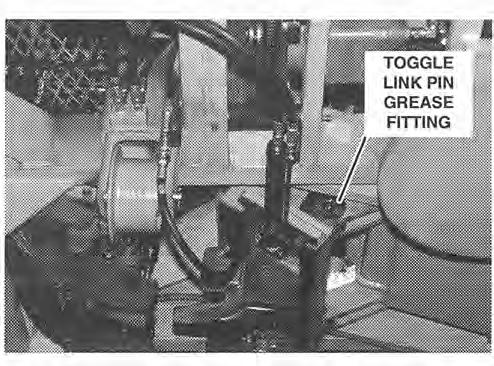
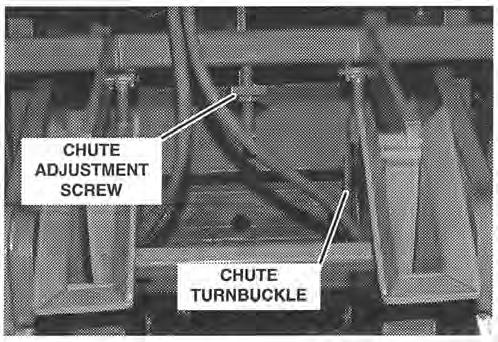
33 Mchine Setup (Continued) 3. Move the Jw Arm in so tht the recess in the nchor holder strddles the ril bse s shown in Illustrtion Check the position of the nchor holder in reltion to the ril bse. There must be 314 inch clernce between the underside of the ril bse nd the nchor holder s shown under "CORRECT ADJUST- MENT" in Illustrtion 27. If the nchor holder is coming in too high nd the clernce between the bottom of the ril bse nd the nchor holder is insufficient, the Clmp Arm Stops must be rised. Conversely, if the nchor holder is coming in too low nd the clernce between the top of the nchor holder nd the underside of the ril bse is excessive, the clmp rm stop must be lowered. TOGGLE TURNBUCKLE The stops on both rms must ber ginst the top of the ril evenly when the clmp rm is down. If one clmp rm stop should strike the ril bse prior to the second stop, the clmp rm will twist. The twisting force exerted on the clmp rm, in this instnce, is excessive nd could dmge the clmp rm ssembly. 5. Move the Jw Arm OUT nd the Clmp Arm UP until the Clmp-Arm Stop djustment screws re ccessible. 6. Loosen the screws nd rise the stops to lower the nchor holders or lower the stops to rise the nchor holders. Tighten the cpscrews nd then recheck the clernce. Repet steps 4 though 6 s necessry to obtin CORRECT ADJUSTMENT. NOTE The TOGGLE LINKAGE djustment below must preceed ANCHOR CHUTE UP-DOWN STOP djustment. C. TOGGLE LINKAGE (see Illustrtion 28). The Toggle Linkge must be djusted nytime different ril widths re encountered. Adjustment of the Toggle Linkge is bsed on the fct tht the Driving Cylinders must be t the end of their stroke when nchors re fully pplied. Adjust Toggle Linkge s follows: 1. Apply set of nchors using the MANUAL mode (see MANUAL OPERATION). But, relese the Jw Arm IN-OUT switch s soon s nchors re fully pplied or the piston rods re fully extended. Illustrtion Mesure the rod stroke ON BOTH CYLINDERS If the piston rod extends 9-15/16" nd the nchor is fully pplied without being over driven, the linkge is djusted correctly. b. If the piston rod is less thn 9-15/16", the toggle linkge must be shortened. This will lengthen the piston rod stroke. c. If the piston rod is fully extended but the nchor is short of ppliction, the toggle linkge must be lengthened. d. If the piston rod is fully extended but the nchor is overdriven, (loose or broken), the toggle linkge must be shortened. IMPORTANT IT IS NECESSARY TO MAKE SURE AD- JUSTMENT IS CORRECT ON BOTH ARMS TO PREVENT TWISTING (DAM- AGE) TO THE JAW ARM. 3. Remove Lock Pin nd djust toggle linkge, if necessry, s follows:. Turn Toggle Turnbuckle CW to lengthen toggle linkge; or b. Turn Toggle Turnbuckle CCW to shorten toggle linkge. NOTE One "flt" rottion of turnbuckle will djust length pproximtely inch.


34 Mchine Setup (Continued) 4. Instll Lock Pin to secure djustment. 5. Apply set of nchors nd recheck length of piston stroke to mke sure it is 9-15/16 inch when nchors re fully pplied. D. ANCHOR CHUTE UP-DOWN STOP. The toggle linkge length estblishes the nchor UP-DOWN pickup point. Anytime the toggle linkge is djusted (s described bove) the UP-DOWN position of the nchor chute must be re-djusted ccordingly. Consequently do not djust the UP-DOWN STOP unless the toggle linkge hs been djusted first. Adjust the UP-DOWN chute position s follows: 1. Rise the clmp rm nd lock it in the rised position with the locking pin. 1 WARNING 1 Do not work on chutes, doors or holders without first locking the clmp rm in the rised position. 2. Drop n nchor in ech nchor chute. 3. With the mchine in MANUAL mode, swing the jw rm ll the wy IN so tht the tool enters the doors. If the chute is in too fr, the tool will push the chute upwrd nd the nchor will be positioned too fr bck in the tool. If the chute is out too fr, the nchor will not be positioned fr enough into the tool for the gripper to hold. 4. Plce the Door Open nd Grip switch in the ON position nd move the jw rm prt wy out. Check the position of the pproprite nchor in the tool s compred with Illustrtion If n djustment is needed, loosen the Locknut on the Adjusting Screw nd move the chute UP or DOWN s required, by turning the Adjusting Screw, in the pproprite direction. See Illustrtion 29. Illustrtion 29 Sliding Jw Opening Width If the mchine is to work on trck tht hs fourteen inch ties, there re two stops on the Jw Arm which must be removed (see Illustrtion 30). This will llow the tool holders to open to their mximum width of fifteen inches. Ech stop is held in plce by two cpscrews. Reinstll these stops immeditely fter completing work on wider ties. Do not operte the mchine on trck with nine inch ties without the stops instlled. The dditionl clernce between the nchor nd tie, without the stops instlled, will ccumulte bllst during the boxing opertion nd the tie will not be properly boxed. STOPS Illustrtion 30
35 Service nd Mintennce Generl Proper mintennce performed t regulr intervls is essentil to good mchine performnce nd opertion. Py prticulr ttention to the intervls specified on the Mintennce Chrt (Tble 7). Periodic inspections re necessry to scertin the effectiveness of mintennce procedures nd the necessity to vry the intervls due to other thn norml conditions. It is recommended tht ccurte mintennce records be kept. Regulrly inspect operting nd mintennce records for devitions from norml stbilized operting conditions. Anlyze the records for indictions of potentil trouble. Also, check the other mnufcturer's literture, in this book, for service nd mintennce informtion (i.e. engines, pumps, etc.). Mintennce Chrt Tble 7, below, lists the items to be serviced nd the intervls t which service is to be performed. The Reference column on the chrt lists the illustrtion number which shows the loction of the item to be serviced. This column my lso refer to detiled instructions for n item which will be under SPECIFIC MAINTENANCE INSTRUCTIONS in this section. Tble 7. Periodic Mintennce Check List Check 8 Hrs. Dily 40 Hrs. Weekly 200 Hrs. Monthly 1000 Hrs. 3 Months 2000 Hrs. 6 Months Refer to Pr.Allust. Engine Oil Level Hydrulic Oil Level J V See Mfgrs. Inst. Mnul Pr. A Fuel Level J Hydrulic Oil Pressure Line Filter V* J Hydrulic Oil Return Line Filter V* V Illust. 31 Hydrulic Oil Suction Line Striner J Oil Cooler Exterior V Bttery Level J Brke Shoes I/ Pr. E Pump Compenstor Pressure nd Relief Vlve Setting Min Pump Relief Vlve Setting I/ I/ Pr. F Pr. F Clmp Arm Down Relief Vlve Setting V Pr. F Gripper Pressure Reducing Vlve Setting I/ Pr. F Propulsion Chin Tension V Pr. D & Illust. 32 LUBRICATE Dul Pump Drive Wheel Bering Grese Fittings (4 e.) V V** V See Mfgrs. Inst. Mnul See Illust. 33 Propulsion Foot Pedls (2 e.) V Toggle Turnbuckle Rod Eye (2 e.) Toggle Turnbuckle Threds (2 e.) V I/ See Illust. 34 See Illust. 34 Clmp Arm Cylinder Rod Eye (2 e.) Toggle Link Pin Bushing (2 e.) V V See Illust. 35 See Illust. 36
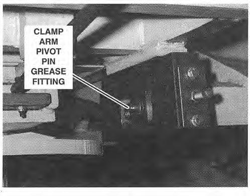
 Jw Arm Pivot Shft (2 e.) Clmp Arm Pivot (2 e.")
 Chute UP-DOWN Adjustment Screw Chute Lterl Adjustment Screw (2 e.")
 8 Hrs. Dily 40 Hrs.")


 therefter. ** Drin, flush nd refill fter first 200 hrs.")
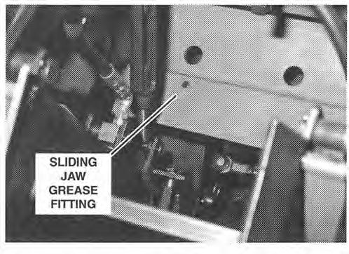
36 Service nd Mintennce (Continued) LUBRICATE (Continued) Jw Arm Sliding Jw (2 e.) Jw Arm Pivot Shft (2 e.) Clmp Arm Pivot (2 e.) Chute Turnbuckle Threds (2 e.) Chute UP-DOWN Adjustment Screw Chute Lterl Adjustment Screw (2 e.) Chute Door Hinge Pin Chute Door Adjustment Screw Tble 7. Periodic Mintennce Check List (Continued) 8 Hrs. Dily 40 Hrs. Weekly v v V v J I/ v V 200 Hrs. Monthly 1000 Hrs. 3 Months 2000 Hrs. 6 Months Refer to Pr./lllust. See Illust. 37 See Illust. 38 See Illust. 39 See Illust. 40 See Illust. 39 See Illust. 40 See Illust. 39 See Illust. 40 Propulsion Drive Chin Propulsion Lever V V See Illust. 39 See Illust. 5 * Inspect filters fter first 40 hours of opertion nd monthly (200 hrs.) therefter. ** Drin, flush nd refill fter first 200 hrs., chnge, oil every 2000 hrs. therefter. NOTE: Service the grese fittings with multipurpose grese. Lubricte other components with engine oil. lllustrtion 31 lllustrtion 33 lllustrtion 34 lllustrtion 32


37 Service nd Mintennce (Continued) lllustrtion 35 lllustrtion 38 lllustrtion 36 lllustrtion 39 lllustrtion 37 lllustrtion 40


 for loction of fittings. C. OIL LUBRICATED COMPONENTS.")


38 Service nd Mintennce (Continued) Illustrtion 41 Illustrtion 42 Specific Mintennce Instructions A. HYDRAULIC RESERVOIR AND FILTERS. The hydrulic system uses SAE-10 to SAE-20 hydrulic oil. The oil tnk should be kept full with 55 gllons of oil. It is impertive tht the hydrulic system be kept clen nd free from dirt nd moisture. There re three oil filters in the hydrulic system which should be chnged or clened when conditions wrrnt. The filters re: The Suction Filter to the smll pump nd min pump, the In- Line Pressure Filter nd the Return Line Filter to the tnk. See the hydrulic system schemtic for the filter loctions. A periodic inspection must be mde to determine whether the filters re strving the pumps of their proper oil supply which would slow down the function of the mchine. The Return Line Filter hs pressure monitoring device which indictes when the filter should be chnged (see ~llustrtion 31). Inspect the filters or check the filter indictors fter the first five hours of opertion nd weekly therefter. These inspections will determine ny chnge in the frequency of the inspections which re necessry. B. GREASE FITTINGS. The grese fittings should be serviced with multipurpose type grese suitble for nti-friction nd sleeve bering pplictions. Check with locl supplier for recommendtions on the proper lubricnt. The grese fittings should be wiped clen before servicing. When servicing sleeve bering fittings, inject sufficient quntity of lubricnt to force the old grese out until the new clen grese - is visible. When servicing nti-friction berings encsed in housing's, the bering cvity will contin the correct mount of grese when the lubricnt begins to come out the sels. See the Mintennce Chrt (Tble 7) for loction of fittings. C. OIL LUBRICATED COMPONENTS. Engine oil should be pplied to the oil lubricted components t the friction surfces of the moving prts. D. PROPULSION CHAIN LUBRICATION AND AD- JUSTMENT. The propulsion chin should'be lubricted weekly with engine oil. The chin Adjustment Screw should be lubricted weekly with Multi-Purpose Bering Grese. Also the propulsion chin is subject to shock loding nd reversl of rottion which cn cuse loosening ofihe chin. The chin should be djusted nerly tut with slight mount of slck, 114" per foot of chin. See Illustrtion 32 nd djust the chin s follows: 1. Loosen Locknut. 2. Turn the Adjusting Screw clockwise to tighten the chin spn nd counterclockwise to loosed the chin. 3. Tighten the djusting screw Locknut. 4. Apply engine oil to entire surfce of chin. E. BRAKE SHOES INSPECTION. To ssure mximum brking efficiency, inspect the brke shoes periodiclly to determine the mount nd type of wer t wheel. Although designed for minimum wer, inspection of ech brke shoe on 6 month bsis is recommended. Brke shoes must be replced when the lining mteril pproches 114 inch thickness.

.")

 t hydrulic reservoir FULLY OPEN. 2. Set up mchine:. Shut-Off Vlve (Illustrtion 9) t hydrulic reservoir FULLY OPEN. b.")
.")
39 Service nd Mintennce (Continued) E HYDRAULIC SYSTEM PRESSURE CHECKS AND ADJUSTMENTS. Pressure to the vrious devices in the hydrulic system re controlled by the Pressure Compenstor nd Relief Vlves. It is importnt for the sfe nd proper opertion of the mchine tht pressures re ccurtely mintined t the correct levels. Therefore, checks should be mde periodiclly s listed on the MAINTENANCE CHART (Tble 7). Adjustments my lso be necessry, nytime the mchine is not operting normlly, s specified on the TROUBLESHOOTING CHART (Tble 8). Test nd djust procedures for ech pressure control device is given below. F1. PRESSURE COMPENSATOR AND IN-LINE RELIEF VALVE. See Illustrtion 43 nd test nd djust vlve s follows: 1. Attch pressure guge to quick disconnect t relief vlve. 2. Set up mchine:. Shut-Off Vlve (Illustrtion 9) t hydrulic reservoir FULLY OPEN. 2. Set up mchine:. Shut-Off Vlve (Illustrtion 9) t hydrulic reservoir FULLY OPEN. b. Engine running t HIGH SPEED (2000 rpm). c. Cold Strt Vlve (Illustrtion 5) CLOSED. b. Engine running t HIGH SPEED (2000 rpm). Illustrtion c. cold Strt Vlve (Illustrtion 5) CLOSED. Turn Compenstor Adjustment Screw IN fully. Turn Relief Vlve Adjusting Screw OUT (two turns). Turn Relief Vlve Screw IN until 2800 psi is obtined t Guge. Replce cp. Turn Compenstor Adjusting Screw OUT to obtin 2500 psi on guge. F2. MAIN PUMP RELIEF VALVE. See Illustrtion 44 nd test / djust vlve s follows: Attch pressure guge to quick disconnect t relief vlve. Illustrtion 44


. c. Cold Strt.Vlve (Illustrtion 5) CLOSED. Illustrtion 45 1.")
. c. Cold Strt Vlve (Illustrtion 5) CLOSED. 3.")


40 Service nd Mintennce (Continued) 3. With Mode Selector Control in MANUALposition, hold Clmp Arm Switch in UP position until djustment is complete. 4. Remove cp nd turn Vlve Adjusting Screw, s necessry, to obtin 2000 psi reding on guge. Replce cp. NOTE Do not remove guge if testing or djusting the Clmp Arm Relief Vlve s described next. F3. CLAMP ARM DOWN RELIEF VALVE. See Illustrtion 45 nd test / djust s follows: F4. GRIPPER PRESSURE REDUCING VALVE. See Illustrtion 46 nd test / djust vlve s follows: 1. Attch pressure guge to quick disconnect ner vlve. 2. Set up mchine:.. Shut-Off Vlve (Illustrtion 9) t hydrulic reservoir FULLY OPEN. b. Engine running t HIGH SPEED (2000 rpm). c. Cold Strt.Vlve (Illustrtion 5) CLOSED. Illustrtion Attch pressure guge to the Min Pump quick disconnect (shown on Illustrtion 44). 2. Set up mchine:. Shut-Off Vlve (Illustrtion 9) t hydrulic reservoir FULLY OPEN. b. Engine running t HIGH SPEED (2000 rpm). c. Cold Strt Vlve (Illustrtion 5) CLOSED. 3. With the Mode Selector Switch in MANUALposition, hold the Clmp Arm Switch in DOWN position until djustment is mde. 4. Remove cp nd turn Vlve Adjusting Screw, s necessry, to obtin 500 psi on guge. Replce cp. Illustrtion With the Mode Selector Switch in MANUAL position, hold Grip nd Door Open Switch in UP position until djustment is mde. 4. Loosen Locknut nd turn screw, s necessry, to obtin 600 psi on guge. Tighten Locknut fter pressure is correct. G. LIMIT SWITCHES. There re five limit switches which re responsible for sending input signls to the logic system for utomtic opertion. The limit switches re composed, essentilly, of two component prts: the opt0 switch nd the ctutor (vne). The opt0 switch hs trnsmitter nd receiver section, ech seprted by slot or ir spce. The receiver section hs light sensitive photocell which, when exposed to the light from the trnsmitter, sends n electricl signl to the logic system. The ctutor is vne which is synchronized with


 position. GI. UP-OPT0 SWITCH.")


. If lit, proceed to step 6.")
. Turn Adjusting Screw to move Switch down until light goes out.")
41 Service nd Mintennce (Continued) the operting sequence so s to block or expose the light from the trnsmitter t precise times during the utomtic sequence. For the opt0 switches to perform properly, it is necessry for the component prts to be positioned correctly. Adjustment for ech of the opt0 switches is described below. pgig-1. The engine must be shutdown whenever the opt0 switches re to be djusted. This will prevent ny possibility of ny of the hydrulic devices indvertently being ctuted during the djustment procedure. Before strting the engine, lwys mke sure the utomtic operting mode is not on by plcing the Mode Selector switch in themanual or OFF (center) position. GI. UP-OPT0 SWITCH. The UP-Opto Switch is responsible for trnsmitting signl which tells the logic system when the Clmp Arm hs reched its mximum up position. To djust the Up-Opto switch for proper synchroniztion,. proceed s follows: With the engine running nd Mode Selector Switch in the MANUAL mode, move the Clmp Arm to the extreme up position. Shutdown the engine nd put Mode Selector Switch in AUTOMATIC position. Remove cover from Opto Switch Box (see Illustrtion 47). Remove Hir Pin Cotter from Up Adjusting Screw. Check Logic Box to see if "UP" input light is lit (see Illustrtion 48). If lit, proceed to step 6. If not lit, turn Adjusting Screw s necessry to move Switch towrd slot in Vne until UP light is lit. (The switch should be t bottom of Vne Slot). Turn Adjusting Screw to move Switch down until light goes out. ADJUSTING SCREW Illustrtion 47 Counting the turns, move Switch upwrd until light comes on nd continue up until light just goes out gin. Illustrtion 48 HAIRPIN COlTER VANE DOWN SWITCH UP SWITCH Move Switch bck down Vne the of 10. Strt engine nd, using mnul controls, move turns tken in step 7 (this will plce switch mid-wy Clmp Arm down bout 12 inches. in Vne slot nd input signl light should be lit t full intensity). 11. Shutdown engine nd put Mode Selector Switch in AUTOMATIC position. Check Logic Box to be cer- 9. Instll Hirpin Cotter nd box cover. tin "UP" input light is NOT lit.


. 4. Remove Hirpin Cotter from Down Adjusting Screw. 5.")


42 Service nd Mintennce (Continued) G2. DOWN-OPT0 SWITCH. The Down-Opto Switch is responsible for trnsmitting signl which tells the logic system when the clmp rm hs reched its mximum downwrd position. To djust the Down-Opto Switch for proper synchroniztion, proceed s follows: 1. With the engine running, use mnul control to move Clmp Arm to extreme down position. 2. Shutdown the engine nd plce the Mode Selector Switch in AUTOMATIC position. 3. Remove cover from Opto Box (see Illustrtion 47). 4. Remove Hirpin Cotter from Down Adjusting Screw. 5. Turn Adjusting Screw to move switch down until "DOWN light t Logic Box (Illustrtion 48) just goes out. 6. Turn Adjusting Screw to move switch upwrd to the point t which light is lit t full intensity. Continue to move switch upwrd n dditionl 118 inch. 7. Instll Hirpin Cotter nd box cover. 8. With engine running, use mnul control to move Clmp Arm up bout 12 inches. 9. Shutdown engine nd put Mode Selector Switch in AUTOMATIC position. Check Logic Box to mke sure "DOWN" input light is NOT lit. G3.OUT-OPT0 SWITCH. The Out-Opto Switch is responsible for trnsmitting signl which tells the logic system when the jw rm is in the out position. Adjust the Out-Opto Switch s follows: HAIRPIN - COlTER BOX SWITCH Illustrtion 49 ADJUSTING SCREW VANE OUT SWITCH Move Switch bck down Vne hlf the mount of turns tken in step 7 (this will plce switch mid-wy in Vne slot nd input signl light should be lit t full intensity). Instll Hirpin Cotter nd box cover. Strt engine nd, using mnul controls, move Jw Arm inwrd bout 6 inches. 11. Shutdown engine nd put Mode Selector Switch in 1. With the engine running, use mnul control to AUTOMATIC position. Check Logic Box to be cermove Jw Arm to the extreme out position. tin "OUT" input light is NOT lit. 2. Shutdown engine nd put Mode Selector Switch in G4. BOX-OPT0 SWITCH. AUTOMATIC position. 1. With engine running, hold the Grip nd Door Open 3. Remove cover from Opto-Switch Box (see Illustr- Switch in the UP (on) position. tion 49). NOTE 4. Remove Hirpin Cotter from Out Adjusting Screw. It is necessry to mintin the Grip nd Door 5. Check Logic Box to see if "OUT" input light is lit Open switch in the ON position throughout this (see Illustrtion 48). If lit, proceed to step 6. If not djustment or the nchors will fll out of the lit, turn Adjusting Screw s necessry to move Switch towrd slot in Vne until OUT light is lit. (The switch should be t bottom of Vne Slot). 6. Turn Adjusting Screw to move Switch down until light goes out. 7. Counting the turns, move Switch upwrd until light comes on nd continue up until light just goes out gin. tools. If there re not nchors in the tools it will be necessry to pick up nchors using MANU- AL control before continuing this procedure.

 Switch s follows: NOTE SIN 200 nd lter mchines hve the Limit Switch")
. The light should NOT be lit.")
 Switch towrd Vn until \"BRAKE\" light t Logic Box comes on. Mrk loction.")
. 5. Remove Hirpin Cotter from Box Adjusting Screw.")


 Switch to point midwy between the two mrks. e. Tighten Mounting Nuts. H.")
43 Service nd Mintennce (Continued) 2. With the Mode Selector Switch in MANUAL position, lower Clmp Arm nd move the Jw Arm in until the nchor extends 112 inch under the ril bse s shown in Illustrtion 50. nd for mchine trvel. Adjust the Brke-Opto (or Brke-Limit) Switch s follows: NOTE SIN 200 nd lter mchines hve the Limit Switch in plce of the Opto Switch. 1. Strt mchine. 2. Check "BRAKE" input light t Logic Box (see I1- lustrtion 48). The light should NOT be lit. If light is on, see Illustrtion 51 nd:. Loosen two Mounting Nuts. b. Move Opto (or Limit) Switch towrd Vn until "BRAKE" light t Logic Box comes on. Mrk loction. Illustrtion Shutdown engine nd put Mode Selector Switch in AUTOMATIC position. 4. Remove cover from Opto Switch Box (see Illustrtion 49). 5. Remove Hirpin Cotter from Box Adjusting Screw. 6. Check Logic Box to see if "BOX input light is lit (see Illustrtion 48). If lit, proceed to step 7. If not lit, turn Adjusting Screw s necessry to move Switch towrd top of Vne until BOX light is lit (the switch should be just bove top of Vne). 7. Turn Adjusting Screw to move Switch down until light just goes out. 8. Turn Adjusting Screw to move switch upwrd to the point t which light is lit t full intensity. Continue to move switch upwrd n dditionl 118 inch. 9. Instll Hirpin Cotter nd box cover. 10. Strt engine nd, using mnul controls, move Jw Arm inwrd bout 6 inches. 11. Shutdown engine nd put Mode Selector Switch in AUTOMATIC position. Check Logic Box to be certin "OUT" input light is NOT lit. G5. BRAKE-OPT0 (or BRAKE-LIMIT) SWITCH. The Brke-Opto / Brke-Limit Switch signls the logic system whenever either Propulsion Foot Switch is depressed. The logic system, in turn, cuses the brke hydrulic cylinder to retrct, thereby relesing the brke c. Continue to move Opto (or Limit) Switch until light comes on nd gin mrk loction. d. Move Opto (or Limit) Switch to point midwy between the two mrks. e. Tighten Mounting Nuts. H. PRESSURE SWITCHES. Two pressure switches re prt of the logic system, which controls the vrious mchine functions. A detiled description nd djustment procedure for ech is given below. HI. IN PRESSURE SWITCH. The In Pressure Switch is responsible for trnsmitting signl to the logic system when the nchors re pplied nd the Jw Arm meets immovble resistnce, the pressure builds up t the pressure side of the driving cylinder until the In Pressure Switch is ctuted. Once the pressure switch is ctuted, the hydrulic pressure to the driving cylinder is discontinued. Illustrtion 51 39


 inwrd (clockwise) until Clmp Arm will")


 to increse pressure or outwrd")

44 Service nd Mintennce (Continued) There re two conditions where the In Pressure Switch requires djustment: when the pressure setting is either too high or too low. When the pressure setting t the pressure switch is higher thn the system relief pressure, the pressure switch will never ctute nd the operting sequence sill stop t pplying the nchors. If the pressure switch ctutes before the nchors re pplied, the pressure setting is too low nd must be incresed. To djust the In Pressure Switch, proceed s follows: NOTE It will require two people to djust pressure switch setting; one to initite utomtic cycle nd nother to djust pressure t switch. 1. Strt mchine. 2. Put Mode Selector Switch in AUTOMATIC position. 3. While one person initites utomtic cycle, turn Adjusting Screw t pressure switch (see Illustrtion 52) inwrd (clockwise) until Clmp Arm will not return from under ril. Pressure Switch will send n input signl to the logic system. The logic system will then stop the operting sequence nd the mchine will return to the redy position. However, if the mchine borts, during the utomtic cycle, without ny prt of the mchine hitting some bnorml obstruction, the pressure setting is too low. The pressure switch should be djusted so tht the lowest possible pressure setting llows the mchine to go through norml utomtic cycle without borting. Strt the pressure switch t low setting nd lterntely operte the mchine nd increse the pressure setting until the mchine completes the cycle without borting. To djust the Abort Pressure Switch proceed s follows: NOTE It will require two people to djust pressure switch setting; one to initite utomtic cycle nd nother to djust pressure t switch. 1. Strt mchine. 2. Put Mode Selector Switch in AUTOMATIC position. 3. While one person continully initites utomtic cycle, turn Adjusting Screw t Abort Pressure Switch (see Illustrtion 52) s necessry to obtin smooth opertion t lowest setting without mchine borting. Turn screw inwrd (clockwise) to increse pressure or outwrd (counterclockwise) to reduce pressure. I. CLAMP ARM UP AND DOWN FLOW CONTROL VALVE ADJUSTMENT. The Clmp Arm should move up nd down in smooth nd rpid motion. If the rm moves too slowly or slms into either the up or down position, see Illustrtion 53 nd djust s follows: Illustrtion Turn Adjusting Screw outwrd until Clmp Arm comes out from under ril nd completes cycle. 5. Repet cycling nd djustment s necessry to obtin smooth opertion. H2. ABORT PRESSURE SWITCH. The Abort Pressure Switch is responsible for signlling the logic system when hzrdous operting condition exists d the operting sequence should be discontinued. If the nchors, sliding jws, or ny other prt of the jw rm ssembly should hit the tie, the ril, lrge stone, or some object which offers bnorml opposition, the Abort Illustrtion 53
 t hvdrulic reser- I.' voir FULLY OPEN. pel the mchine nd relese the brkes, it my be necessry to djust the Propulsion Flow Control Vlve s follows: 1.")
 CLOSED. d. Mode selector Switch in MANUAL position. Loosen Jm Nut t UP Flow Control Vlve (see 11- lustrtion 53).")

45 Service nd Mintennce (Continued) NOTE It will require two people to djust pressure switch setting; one to initite the cycle nd nother to djust vlve. 1. Set up:. Shut-Off Vlve (Illustrtion 9) t hvdrulic reser- I.' voir FULLY OPEN. pel the mchine nd relese the brkes, it my be necessry to djust the Propulsion Flow Control Vlve s follows: 1. Loosen the Locking,Screw nd turn the knob outwrd (counterclockwise) until it stops. See Illustrtion 54. b. Engine running t HIGH SPEED (2000 rpm). c. Cold Strt Vlve (Illustrtion 5) CLOSED. d. Mode selector Switch in MANUAL position. Loosen Jm Nut t UP Flow Control Vlve (see 11- lustrtion 53). While one person opertes Clmp Arm Up-Down Switch, djust UP Flow Control Vlve Knob until Clmp Arm cycles smoothly without "slmming" into the Up position. 4. Repet steps 2 nd 3 t the Down Flow Control Vlve until Clmp Arm cycles smoothly without "slmming" down ginst ril. J. PROPULSION FLOW CONTROL VALVE AD- JUSTMENT. To ssure sufficient pressure to both pro- Illustrtion Turn the knob inwrd (clockwise) three complete turns. Tighten the Locking Screw.
46 Service nd Mintennce (Continued) Troubleshooting Troubleshooting is mtter of quickly nd logiclly isolting the cuse of problem nd tking corrective ction. Operting experience, thorough understnding of the informtion in this mnul, nd ccurte mintennce nd opertion records re the best troubleshooting tools n opertor cn hve. When problem occurs, logicl nlysis of the problem nd symptom should led to the cuse nd pproprite remedy. This troubleshooting chrt.is only n id in the event this method fils., Troubleshooting Chrt (Tble 8) It is difficult to nticipte wht kind of field problems cn occur. Locl conditions nd operting methods my result in problems, cuses nd remedies not covered in this guide. To use the guide most efficiently, locte the problem tht mtches the one being experienced nd, in step by step method, check the cuses listed until the correct remedy is found nd the problem solved. Reference is mde to djustment procedure prgrph numbers under SPECIFIC MAINTENANCE INSTRUC-.TIONS, where pproprite. Also mke sure to consult the troubleshooting sections of the mnufcturers' literture (in the Component Dt section) for ll components not mnufctured by RMEC. Tble 8. Troubleshooting Chrt PROBLEM 1. Engine does not crnk. 2. Engine crnks but does not run. 3. Pump does not develop pressure. POSSIBLE CAUSE 1.1 Circuit brekers tripped. 1.2 Bttery ded. 1.3 Strter defective. 2.1 Engine not getting fuel Engine defective. 3.1 No hydrulic oil in tnk. (NOTE: If pump is run with no oil in tnk, pump dmge will result). 3.2 Suction line vlve closed (NOTE: Running pump with vlve closed will result in pump dmge. 3.3 Engine cold strt vlve open (smll pump only). REMEDY First determine cuse of electricl over lod nd correct. Then reset the circuit breker Check cid level in ech cell nd dd wter if required. Rechrge bttery, recheck cid level Repir or replce Check fuel tnk nd fill if necessry Check fuel line shut-off vlve on bottom of fuel tnk to mke certin it is open Check for plugged or broken fuel hoses. Clen or replce hose Check fuel filters for wter. Drin if necessry Check fuel filter elements for dirt. Replce if clogged Refer to engine mnul for troubleshooting engine Add sufficient oil to tnk to bring oil level bove the dd mrk on the dipstick Open vlve completely (See Illustrtion 9) Close vlve.
47 Service nd Mintennce (Continued) Tble 8. Troubleshooting Chrt (Continued) PROBLEM 4. Mchine will not propel. 5. Brkes will not relese. 6. Brkes will not pply. 7. Door cylinder will not operte. POSSIBLE CAUSE 3.4 Relief vlve bypssing. (NOTE: Oil blowing pst ny relief vlve will cuse oil to overhet. 3.5 Smll pump compenstor setting too low. 3.6 Defective pump. 3.7 Set-Off Cylinder Selector Vlve in center position. 4.1 Smll pump not developing pressure. 4.2 Brkes not relesing. 4.3 Propulsion flow control setting incorrect. 4.4 Defective motor. 5.1 Smll pump not developing pressure. 5.2 Brke vlve not shifting. 5.3 Brke opt0 switch uncovered or not djusted correctly. 5.4 Defective opt0 switch or limit switch 5.5 Brke cylinder bypssing oil. 6.1 Brke vlve not shifting. 6.2 Broken brke spring. 6.3 Brke shoes worn. 6.4 Brke opt0 switch or limit switch uncovered or not djusted correctly. 6.5 Defective opt0 switch. 7.1 Mode Selector Switch in OFF position. 7.2 Cold Strt Vlve open. 7.3 Circuit Breker tripped. 7.4 Logic Circuit Bord fuse blown. 7.5 Defective Logic Bord. REMEDY Increse pressure setting on relief vlve (see pr. F). NOTE: Relief setting must be psi bove compenstor setting lncrese compenstor setting (see pr. F1) Refer to pump mnul for troubleshooting pump Return Selector Vlve to DOWN position See problem # See problem # Increse setting (see pr. J) Replce motor See problem # Check pump for wer or dmge Check vlve spool for free motion nd tht solenoid is being energized Inspect switch nd clen if necessry (see pr. G5) Replce switch lnspect nd repck cylinder Check vlve spool for free motion nd tht solenoid is being de-energized Inspect spring nd replce if necessry Inspect shoes nd replce if necessry lnspect switch nd vne. Clen or redjust if necessry (see pr. G5) Replce switch Put Mode Selector Switch in AUTO or MANUAL position Close Cold Strt Vlve Determine course of electricl overlod nd correct. Reset Circuit Breker Determine cuse of electricl overlod nd correct. Replce fuse Troubleshoot Logic Bord by qulified electricin (see Sequence Chrt-Tble 9) or cll Nordco Service Deprtment.
48 Service nd Mintennce (Continued) Tble 8. Troubleshooting Chrt (Continued) PROBLEM 8. Boxing Cylinder will not operte. 9. Grippers do not grip nd hold nchors. 1 G Set-Off Cylinder does not operte. POSSIBLE CAUSE 7.6 No hydrulic pressure. 7.7 Control vlve dirty or defective. 8.1 Mode Selector Switch in OFF position. 8.2 Cold Strt Vlve open. 8.3 Circuit Breker tripped. 8.4 Logic Circuit Bord fuse blown. 8.5 Defective Logic Bord. 8.6 No hydrulic pressure. 8.7 Control vlve dirty or defective. 8.8 Box opt0 switch not in djustment. 8.9 Box opt0 switch defective. 9.1 Mode Selector Switch in OFF position. 9.2 Cold Strt Vlve open. 9.3 Circuit Breker tripped. 9.4 Logic Circuit Bord fuse blown. 9.5 Defective Logic Bord. 9.6 No hydrulic pressure. 9.7 Control vlve dirty or defective. 9.8 Pressure Reducing Vlve not in djustment. 9.9 Pressure Reducing Vlve defective Quick disconnect not connected Cold Strt Vlve open Loss of hydrulic pressure. REMEDY See problem # Clen or replce Control Vlve (see mfrs. instructions in Component Dt section Put Mode Selector Switch in AUTOMATIC or MANUAL position Close Cold Strt Vlve Determine cuse of electricl overlod nd correct. Reset Circuit Breker Determine cuse of electricl overlod nd correct. Replce fuse Troubleshoot Logic Bord by qulified electricin (see Sequence Chrt-Tble 9) or cll RMEC Service Dept See problem # Clen or replce Control Vlve (see mfgrs instructions in Component Dt section) Adjust switch (see pr. G4 in this section) Replce switch. 9.1.I Put Mode Selector Switch in AUTOMATIC or MANUAL position Close Cold Strt Vlve Determine cuse of electricl overlod nd correct. Reset Circuit Breker Determine cuse of electricl overlod nd correct. Replce fuse Troubleshoot Logic Bord by qulified electricin (see Sequence Chrt-Tble 9) or cll Nordco Service Dept See problem # Clen or replce Control Vlve (see mfgrs instructions in Component Dt section) Adjust vlve (see pr.f4) Replce vlve Connect hydrulic hose t disconnect Close vlve See problem #3.
49 Service nd Mintennce (Continued) Tble 8. Troubleshooting Chrt (Continued) PROBLEM 11. Clmp Arm Up- Down Cylinder does not operte or opertes too slow. 12. Jw Arm In-Out Cylinder does not operte or opertes too slow. (Jw Arm is down but will not come in to pply nchors). POSSIBLE CAUSE 11.1 Mode Selector Switch in OFF position Cold Strt Vlve open Circuit Breker tripped Logic Circuit Bord fuse blown Defective Logic Bord No hydrulic pressure Control vlve dirty or defective Up or Down Opto Switch out of djustment Out Opto Switch covered Mode Selector Switch in OFF position Cold Strt Vlve open Circuit Breker tripped Logic Circuit Bord fuse blown Defective Logic Bord No hydrulic pressure Control vlve dirty or defective Jw Arm hits obstruction nd ctivtes Abort Pressure Switch Abort Pressure Switch out of djustment or defective Abort Pressure Switch set too low. REMEDY Put Mode Selector Switch in AUTO or MANUAL position Close Cold Strt Vlve Determine cuse of electricl overlod nd correct. Reset Circuit Breker Determine cuse of electricl overlod nd correct. Replce fuse Troubleshoot Logic Bord by qulified electricin (see Sequence Chrt - Tble 9) or cll Nordco Service Dept See problem # Clen or replce Control Vlve (see mfgrs. instructions in Component Dt section) Adjust Opto Switch (see pr. G in this section) Adjust Out Opto Switch (see pr. G3 in this section) Put Mode Selector Switch in AUTO or MANUAL position Close Cold Strt Vlve Determine cuse of electricl overlod nd correct. Reset Circuit Breker Determine cuse of electricl overlod nd correct. Replce fuse Troubleshoot Logic Bord by qulified electricin (see Sequence Chrt - Tble 9) or cll Nordco Service Dept See problem # Clen or replce Control Vlve (see mfgrs instructions in Component Dt section) Shutdown engine, remove obstruction nd use MANUAL mode to complete cycle Adjust Abort Pressure Switch (see pr. H2) Adjust switch (see pr. H2).
50 Service nd Mintennce (Continued) Tble 8. Troubleshooting Chrt (Continued) PROBLEM (Jw Arm does not return to OUT position fter pplying nchors). 13. Winch (option) does not operte. POSSIBLE CAUSE Down Opto Switch covered In-Pressure Switch set too high Cold Strt Vlve open No hydrulic pressure. REMEDY Adjust Opto switch (see pr. G2 in this section) Adjust switch (see pr. H1 in this section) Close vlve See problem #3. Function Sequence Chrt Tble 9 is provided for the use of qulified electricl technicins troubleshooting the logic system. The chrt shows the sequence of lit LEDs s the vrious mchine functions occur. All the LEDs re listed cross the top of the tble. The ctions or functions of the mchine re listed, long the side of the tble, in the order in which they occur. Refer to Illustrtion 48 for the loction of the LEDs on the PCB.
 ARM STARTING UP n m. CLAMP ARM MOVING UP rn. CLAMP ARM UP- JAW ARM STARTING IN JAW ARM MOVING IN JAW ARM IN-GRIPPING ANCHORS- DOORS OPEN JAW ARM START.")
51 CLAMP ARM DOWN - JAW ARM STARTING IN JAW ARM MOVING IN BOXING ANCHORS-UNGRIPPING JAW ARM IN-ANCHORS ON % JAW ARM STARTING OUT P,q JAW ARM MOVING OUT D Z 0 JAW ARM MOVING OUT-UNBOXING z 0 n JAW ARM OUT-CLAMP V) ARM STARTING UP n m. CLAMP ARM MOVING UP rn. CLAMP ARM UP- JAW ARM STARTING IN JAW ARM MOVING IN JAW ARM IN-GRIPPING ANCHORS- DOORS OPEN JAW ARM START. OUT JAW ARM MOVING OUT JAW ARM OUT - END OF CYCLE START APPLY CYCLE - CLAMP ARM STARTING DOWN CLAMP ARM MOVING DOWN CLAMP ARM DOWN- JAW ARM STARTING IN JAW ARM MOVING IN ANCHOR HITS OBSRUCTION - ABORTS CYCLE - JAW ARM STARTING OUT JAW ARM MOVING OUT JAW ARM OUT-CLAMP ARM STARTING UP CLAMP ARM MOVING UP CLAMP ARM UP- READY TO RESTART CYCLE.6 'Z 0 n I rn 0 0 < P rn

. b. Inspect cble for fryed wire or kinks in cble.")
52 Boom nd Winch Description An optionl boom nd hydrulic winch is vilble for this mchine. The min use of the winch is for the loding of nchor bgs nd dditionl equipment. The boom cn be rotted in its bse nd the winch rolls on n I- bem trck for esy positioning of lods. The lift cpcity of this unit is 300 lbs. Opertion. To position the boom, disengge Boom Interlock Pin nd swing boom to desired position. b. Winch rolls in or out on trck. c. Winch up-down opertion is controlled by pull chin. Service Do not exceed 300 lb. lift cpcity. Do not trvel or work mchine unless boom is locked nd Winch is secured.. Lubricte boom t both Grese Fittings every 1000 hrs. (3 months). b. Inspect cble for fryed wire or kinks in cble. Replce dmged cble immeditely.
POWER TRIM. Table of Contents. Section 5D - Auto Trim II
 SERVICE MANUAL NUMBER 14 Tble of Contents POWER TRIM Section 5D - Auto Trim II AUTO TRIM II 1 B Auto Trim II System................. 5D-2 Description...................... 5D-2 Auto Trim II Opertion...............
POWER TRIM. Table of Contents. Section 5D - Auto Trim II
 SERVICE MANUAL NUMBER 11 Tble of Contents POWER TRIM Section 5D - Auto Trim II AUTO TRIM II Auto Trim II System................... 5D-2 Description........................ 5D-2 Auto Trim II Opertion.................
FUEL SYSTEM. Section 3A Pulse Crankcase Driven Fuel Pump. Model 200/225 DFI. 1. Fuel Pressure/Vacuum Gauge (0-15 psi) (Obtain Locally)
 (Obtain Locally)") FUEL SYSTEM Section 3A Pulse Crnkcse Driven Fuel Pump Tle of Contents Specifictions................................ 3A-1 Specil Tools................................ 3A-1 Fuel Pump..................................
FUEL SYSTEM Section 3A Pulse Crnkcse Driven Fuel Pump Tle of Contents Specifictions................................ 3A-1 Specil Tools................................ 3A-1 Fuel Pump..................................
FUEL SYSTEM. Table of Contents. Specifications. Section 3A Electric Fuel Pump FUEL SYSTEM. Fuel Recommended Gasoline Recommended Oil
 FUEL SYSTEM Section 3A Electric Fuel Pump Tble of Contents Specifictions........................... 3A-1 Fuel Pump Assembly.................... 3A-2 Specil Tools........................... 3A-3 Fuel Lift
UPS Pure Sinewave UPS
 UPS Pure Sinewve UPS USR S MANUAL 1.6K / 3.2K / 5KVA 6.4K / 8K/ 10KVA 1. INTRODUCTION 1. 1.1 Generl Description This UPS, powerful ll-in-one solution, delivers unsurpssed clen true sine wve output power
Technical Publications Z Service Manual. First Edition Part No
 Technicl Publictions Z-45 22 Service Mnul First Edition Prt No. 29487 Introduction Service Mnul - First Edition Importnt Red, understnd nd obey the sfety rules nd operting instructions in the Genie Z-45/22
ELECTRICAL SYSTEM 4 D INSTRUMENTATION
 ELECTRICAL SYSTEM 4 D 72747 INSTRUMENTATION Tle of Contents Pge Identifiction............................. 4D-1 Specil Informtion....................... 4D-1 Lighting Options....................... 4D-1
ABB industrial drives. Mechanical installation instructions ACS880 multidrive cabinets
 ABB industril drives Mechnicl instlltion instructions ACS880 multidrive cbinets List of relted mnuls Generl drive mnuls (in ll deliveries) Electricl plnning instructions for ACS880 multidrive cbinets nd
FUEL SYSTEM. Table of Contents. Section 3C Oil Injection
 Tle of Contents FUEL SYSTEM Section 3C Oil Injection OIL INJECTION Specil Tools................................ 3C-2 Oil System Opertion......................... 3C-2 Oil Pump Output..........................
IGNITION SYSTEM SERVICE MANUAL NUMBER
 IGNITION SYSTEM SERVICE MANUAL NUMBER 26 Specifictions Timing Timing (At Idle rpm) 1 1 BTDC 2 / 1 ATDC 3 / 2 ATDC 4 1 Timing must be set using specil procedure s outlined in this section. Timing cnnot
Spring Return DuraDrive Two-Position Actuator
 MA40-704x Series, MA4-707x Series, nd MA4-75x Series Spring Return DurDrive Two-Position Actutor For spring return pplictions tht require twoposition control of dmpers nd vlves in HVAC system. Fetures:
CC-410 KIT SERIES INSTRUCTION SHEET
 (COMPLETE CC-410-W KIT ILLUSTRTED. CUT-OUTS IN TRCK & FSCI TO EXPOSE COMPONENTS) CC-410 KIT SERIES INSTRUCTION SHEET CROWDERTRCK S CTCH N CLOSE TM SYSTEM PREVENTS BOUNCING ND SLMG OF SLIDING DOORS. CN
JET PUMP. Table of Contents. Section 5 - Jet Pump
 Tble of Contents JET PUMP Section 5 - Jet Pump JET PUMP Generl Informtion..................... 5-2 Principles of Opertion................ 5-2 Mster Specifictions Jet Pump........... 5-3 Specil Tools........................
Spark Plug Fouling 3.0 Liter OptiMax
 WARRANTY INFORMATION PARTS INFORMATION SERVICE INFORMATION Bulletin No. 2002-07 Circulte to: Sles Mnger Accounting Service Mnger Technicin Prts Mnger Sprk Plug Fouling 3.0 Liter OptiMx Models Affected
CCS-810 KIT SERIES INSTRUCTION SHEET
 (COMPLETE KIT ILLUSTRTED. CUT-OUTS IN TRCK & FSCI TO EXPOSE COMPONENTS) CCS-810 KIT SERIES INSTRUCTION SHEET CROWDERTRCK S CTCH N CLOSE TM SYSTEM PREVENTS BOUNCING ND SLMMING OF SLIDING DOORS. CN BE INSTLLED
AIRCRAFT ENGINES SERVICE INSTRUCTION ENGINE START AT LOW TEMPERATURES AT ROTAX SI R1
 d03161 RECOMMENDED AIRCRAFT ENGINES SERVICE INSTRUCTION ENGINE START AT LOW TEMPERATURES AT ROTAX ENGINE TYPE 912 AND 914 (SERIES) Repeting symbols: Plese, py ttention to the following symbols throughout
CONTROL VALVES FOR GRINDER. Installation, Maintenance and Operating Instructions 5 GA 71 en Issue 5/02
 CONTROL VALVES FOR GRINDER Instlltion, Mintennce nd Operting Instructions 5 GA 71 en Issue 5/02 2 Tble of Contents 1 OPERATION......................... 3 1.1 Generl......................... 3 1.2 Min components.................
11 263/ Radial Piston Pump Model R4 /Series 2X Fixed Displacement. Ordering Code 1 PF 1 R4 2X R Replaces:
 ize.60 to 0.00 Rdil iston ump Model R4 /eries X Fixed Displcement 0,0 I (00 br).9 in /rev (9.4 cm /rev) RA 6/0.9 RA 6/0.9 Replces: 06.89 K 6/ Rdil piston pump with 0 pistons nd prllel shft Chrcteristics:
631 ALLOWANES AND TOLERANCES
 631 ALLOWANES AND TOLERANCES ANSI Fits. Tbles 3 through 9 inclusive show series of stndrd types nd clsses of fits on unilterl hole bsis, such tht the fit produced by mting prts in ny one clss will produce
CCD-493 KIT SERIES INSTRUCTION SHEET
 (COMPLETE CCD-493-W KIT ILLUSTRTED. CUT-OUTS IN TRCK TO EXPOSE COMPONENTS) CCD-493 KIT SERIES INSTRUCTION SHEET CROWDERTRCK S CTCH N CLOSE TM SYSTEM PREVENTS BOUNCING ND SLMMING OF SLIDING S. CN BE INSTLLED
DIEBOLD 5550 CASH DISPENSER THROUGH 330mm (13") MAXIMUM WALL PLAN VIEW FRONT ELEVATION SIDE ELEVATION CONSUMER ACCESS DIMENSIONS
 MAXIMUM WALL PLAN VIEW FRONT ELEVATION SIDE ELEVATION CONSUMER ACCESS DIMENSIONS") L0 CLL -800--600 R DIEBOLD 0 CSH DISPENSER THROUGH 0mm (") MXIMUM WLL mm ( " ) UL CONSULT WITH DIEBOLD INSTLLTION/SERVICE BRNCH FOR DDITIONL DETILS ND INFORMTION. PLESE SEE PLNNING ND SITE PREPRTION GUIDE
L0 CLL -800--600 R DIEBOLD 0 CSH DISPENSER THROUGH 0mm (") MXIMUM WLL mm ( " ) UL CONSULT WITH DIEBOLD INSTLLTION/SERVICE BRNCH FOR DDITIONL DETILS ND INFORMTION. PLESE SEE PLNNING ND SITE PREPRTION GUIDE
 tel. +44 (0) 28 37 518111 fx +44 (0) 28 37 528181 e.mil sles@technidrive.co.uk points for considertion when shft mounting direct drive ger units. modern hollow bore output hub ger units lend themselves
Installation and Operational Instructions for ROBA -slip hubs Sizes 0 12 (B.1.0.GB)
") Plese red these Opertionl Instructions crefully nd follow them ccordingly! Ignoring these Instructions my led to mlfunctions or to clutch filure, resulting in dmge to other prts. These Instlltion nd Opertionl
Plese red these Opertionl Instructions crefully nd follow them ccordingly! Ignoring these Instructions my led to mlfunctions or to clutch filure, resulting in dmge to other prts. These Instlltion nd Opertionl
DPST-NO None 2 channels Auto-reset Inverse 24 VAC/VDC G9SB-2002-A 4 1 channel or 2
 Sfety Rely Unit Ultr Slim Sfety Rely Unit Models of width 17.5 mm vilble with 2 or 3 poles. Models of width 22.5 mm with 3 poles lso vilble. Conforms to EN stndrds. (TÜV pprovl) DIN trck mounting possible.
Exercise 2-2. Gearbox, Coupling, and Alignment EXERCISE OBJECTIVE DISCUSSION OUTLINE DISCUSSION. More information about the gearbox. Gear ratio.
 Exercise 2-2 Gerbox, Coupling, nd Alignment EXERCISE OBJECTIVE When you hve completed this exercise, you will be fmilir with the high-speed prt of the drive trin system between the gerbox nd the genertor.
Low Pressure Domestic Burners
 95 CHAPTER 12 Low Pressure Domestic Burners The principle of vporiing oil in low pressure burner is shown in fig. 1. Air nd oil re mixed within the nole, then Y ---U OIL NOZZLE j FIG. 1. Digrm showing
330mm (13") MAXIMUM WALL THICKNESS IN AREA OF UNIT. 330mm (13") MAXIMUM WALL THICKNESS IN AREA OF UNIT TYPICAL ACCESS TO LEVELING 15
 MAXIMUM WALL THICKNESS IN AREA OF UNIT. 330mm (13) MAXIMUM WALL THICKNESS IN AREA OF UNIT TYPICAL ACCESS TO LEVELING 15") L CLL -800--600 R DIEBOLD 0 CSH DISPENSER THROUGH 0mm (") MXIMUM WLL 0mm ( 6" ) CEN I, CEN III GS, or CEN IV GS SFES CONSULT WITH DIEBOLD INSTLLTION/SERVICE BRNCH FOR DDITIONL DETILS ND INFORMTION. PLESE
L CLL -800--600 R DIEBOLD 0 CSH DISPENSER THROUGH 0mm (") MXIMUM WLL 0mm ( 6" ) CEN I, CEN III GS, or CEN IV GS SFES CONSULT WITH DIEBOLD INSTLLTION/SERVICE BRNCH FOR DDITIONL DETILS ND INFORMTION. PLESE
Application Examples of Air-piloted Valves
 ir-piloted Vlves Fetures Since the unit requires ir piping only, with no need for electricl wiring, it cn e hndled y person without fer of electricl shocks or current lekge. Using no electricity mens tht
4/3, 4/2 and 3/2 explosion-proof solenoid directional valve
 01/06 4/3, 4/2 nd 3/2 explosion-proof solenoid directionl vlve Type G...WE6...L6X 2.21 Size (NG) 6 Up to 350 br Up to 80 L/min Contents Function nd configurtion Specifictions 03 Spool symbols 03 Technicl
Safety Relay Unit. Ordering Information. Ultra Slim Safety Relay
 Sfety Rely Unit Ultr Slim Sfety Rely Unit Models of width 17.5 mm (smllest Unit in the world s of Jnury 2001) vilble with 2 or 3 poles. Models of width 22.5 mm with 3 poles lso vilble. EN stndrds (TÜV
DIEBOLD 3750 CASH RECYCLER TERMINAL. 13mm ( 2") UL SAFE - 15" OR 19" DISPLAY THROUGH THE WALL 330mm (13") PLAN VIEW FRONT ELEVATION SECTION
 UL SAFE - 15 OR 19 DISPLAY THROUGH THE WALL 330mm (13) PLAN VIEW FRONT ELEVATION SECTION") L8 CLL -800--600 R DIEBOLD 0 CSH RECYCLER TERMINL mm ( ") UL SFE - " OR " DISPLY THROUGH THE WLL 0mm (") 64 SFE ( 6 ") CONSULT WITH DIEBOLD INSTLLTION/SERVICE BRNCH FOR DDITIONL DETILS ND INFORMTION. PLESE
L8 CLL -800--600 R DIEBOLD 0 CSH RECYCLER TERMINL mm ( ") UL SFE - " OR " DISPLY THROUGH THE WLL 0mm (") 64 SFE ( 6 ") CONSULT WITH DIEBOLD INSTLLTION/SERVICE BRNCH FOR DDITIONL DETILS ND INFORMTION. PLESE
Electrically operated directional spool valve with a soft-shift function type WE10P NS 10. up to 35 MPa up to 120 DATA SHEET - OPERATION MANUAL
 LICTION Electriclly operted directionl spool vlve with soft-shift function type WE10 NS 10 Electriclly operted directionl spool vlve type WE10 is intended for chnging the direction of fluid flow in hydrulic
ELECTRICAL. Table of Contents. Section 2A - Ignition
 Tble of Contents Specifictions........................... A- Specil Tools........................... A- Flywheel............................... A- Flywheel............................... A-5 Electricl
MO series. Low Level Order Picker 1,000kg / 2,000kg / 2,500kg
 MO series Low Level Order Picker 1,000kg /,000kg /,500kg Scooter control steering device enhnces ergomics nd productivity Extended model rnge nd option offering for tilored solution CANbus techlogy nd
Convenience electronics
 Convenience electronics Displys on "opening" the roof To gurntee high level of sfety, roof movement is ccompnied, depending on the equipment vrint, y opticl, coustic nd/or text displys/indictions. The
DIEBOLD IN LOBBY TELLER (ILT) PORTRAIT OR LANDSCAPE INSTALLED WITH A COIN RECYCLER SIDE CAR PLAN FRONT VIEW SIDE VIEW PAGE 1 OF 7
 PORTRAIT OR LANDSCAPE INSTALLED WITH A COIN RECYCLER SIDE CAR PLAN FRONT VIEW SIDE VIEW PAGE 1 OF 7") L2 CLL -800--600 TP-826-00. R CONSULT WITH DIEBOLD INSTLLTION/SERVICE BRNCH FOR DDITIONL DETILS ND INFORMTION. PLESE SEE PLNNING ND SITE PREPRTION GUIDE DIEBOLD 00 - IN LOBBY TELLER (ILT) PORTRIT OR LNDSCPE
L2 CLL -800--600 TP-826-00. R CONSULT WITH DIEBOLD INSTLLTION/SERVICE BRNCH FOR DDITIONL DETILS ND INFORMTION. PLESE SEE PLNNING ND SITE PREPRTION GUIDE DIEBOLD 00 - IN LOBBY TELLER (ILT) PORTRIT OR LNDSCPE
WATERTIGHT AIRTIGHT SPECIAL ACCESS DOORS & HATCHES, PART 1 GENERAL
 SECTION 08316 WTERTIGHT IRTIGHT SPECIL CCESS DOORS & HTCHES, PRT 1 GENERL HIGHLIGHTED RES TO BE INSERTED BY SPECIFYING ENGINEER. 1.1 WORK OF THIS SECTION. THE WORK OF THIS SECTION INCLUDES PROVIDING LL
* * * DIEBOLD 3700 LOBBY CASH RECYCLER- FRONT LOAD 15" DISPLAY OR 19" DISPLAY CONSUMER ACCESS DIMENSIONS PLAN VIEW 19" DISPLAY FRONT ELEVATION
 R L CLL -0--600 64 SFE ( 6 ") DIEBOLD 00 LOBBY CSH RECYCLER- FRONT LOD " DISPLY OR " DISPLY WITH mm ( ") UL SFE CONSULT WITH DIEBOLD INSTLLTION/SERVICE BRNCH FOR DDITIONL DETILS ND INFORMTION. PLESE SEE
JUMO MIDAS C18 SW. OEM seawater pressure transmitter. Applications. Brief description. Customer benefits. Special features. Approvals/approval marks
 Pge /8 JUMO MIDAS C8 SW OEM sewter pressure trnsmitter Applictions wter tretment reverse osmosis, e.g. sewter deslintion plnts purifiction plnts orgnic cids, e.g. cetic cid solutions contining chloride,
330mm (13") MAXIMUM WALL THICKNESS IN AREA OF UNIT. 330mm (13") MAXIMUM WALL THICKNESS IN AREA OF UNIT (2) EACH SIDE OF SAFE CEN I SAFE ONLY
 MAXIMUM WALL THICKNESS IN AREA OF UNIT. 330mm (13) MAXIMUM WALL THICKNESS IN AREA OF UNIT (2) EACH SIDE OF SAFE CEN I SAFE ONLY") L08 CLL -800--600 R CS 0 FULL FUNCTION TERMINL " OR " DISPLY - THROUGH THE WLL 0mm (") 40mm ( 6") CEN I, CEN III GS OR CEN IV GS SFES SFE CONSULT WITH DIEBOLD INSTLLTION/SERVICE BRNCH FOR DDITIONL DETILS
L08 CLL -800--600 R CS 0 FULL FUNCTION TERMINL " OR " DISPLY - THROUGH THE WLL 0mm (") 40mm ( 6") CEN I, CEN III GS OR CEN IV GS SFES SFE CONSULT WITH DIEBOLD INSTLLTION/SERVICE BRNCH FOR DDITIONL DETILS
Special Valves. Connection size G1/8 to G2. Contents Version Actuation Port size Page Characteristics. Instructions Overview. Electrical G1/8 G1/4
 Contents Version Actution Port size Pge Chrcteristics Dimensions 3/2, 5/2 nd 5/3 Wy Vlves with NAMURconnections Series S9 5/2 Wy Vlves for Two Hnd Opertion Series S9 Time Dely Vlve for 2-Hnd Sfety Strt
203mm (8") MAXIMUM WALL THICKNESS IN AREA OF UNIT NOTE: 203mm (8") MAXIMUM WALL THICKNESS IN AREA OF UNIT (2) EACH SIDE OF SAFE CEN I SAFE ONLY
 MAXIMUM WALL THICKNESS IN AREA OF UNIT NOTE: 203mm (8) MAXIMUM WALL THICKNESS IN AREA OF UNIT (2) EACH SIDE OF SAFE CEN I SAFE ONLY") L0 CLL -800--600 R CS 0 FULL FUNCTION VESTIBULE TERMINL " OR " DISPLY-THROUGH 0mm ( MXIMUM WLL 40mm ( 6") CEN I, CEN III GS or CEN IV GS SFES SFE ( 6 ") CONSULT WITH DIEBOLD INSTLLTION/SERVICE BRNCH FOR
L0 CLL -800--600 R CS 0 FULL FUNCTION VESTIBULE TERMINL " OR " DISPLY-THROUGH 0mm ( MXIMUM WLL 40mm ( 6") CEN I, CEN III GS or CEN IV GS SFES SFE ( 6 ") CONSULT WITH DIEBOLD INSTLLTION/SERVICE BRNCH FOR
Name Model Description/Function. Directional Control Valve Station 5914 Used to activate the Pneumatic Box Feeder B
 Job Sheet 4 PLC-Controlled Conveyor nd Sensors OBJECTIVE To fmilirize yourself with the vrious sensors provided with the Flexible Mnufcturing System nd mesure their respective sensing rnges. To use the
REPLACEMENT. 4. REMOVE WINDSHIELD MOULDING OUTSIDE (a) Using a knife, cut off the moulding, as shown in the illustration.
 Using a knife, cut off the moulding, as shown in the illustration.") 7012 REPLCEMENT The instlltion procedures re the removl procedures in reverse order. However, only instlltion procedures requiring dditionl informtion re included. 1. REMOVE ROOF HEDLINING SSY (See pge
7012 REPLCEMENT The instlltion procedures re the removl procedures in reverse order. However, only instlltion procedures requiring dditionl informtion re included. 1. REMOVE ROOF HEDLINING SSY (See pge
CS 7750 FULL FUNCTION TERMINAL 15" OR 19" DISPLAY - THROUGH THE WALL 330mm (13")
") L08 CLL -800--600 " OR " DISPLY - THROUGH THE WLL 0mm (") 40mm ( 6") CEN I CONSULT WITH DIEBOLD NIXDORF INSTLLTION/SERVICE BRNCH FOR DDITIONL DETILS ND INFORMTION. PLESE SEE PLNNING ND SITE PREPRTION GUIDE
L08 CLL -800--600 " OR " DISPLY - THROUGH THE WLL 0mm (") 40mm ( 6") CEN I CONSULT WITH DIEBOLD NIXDORF INSTLLTION/SERVICE BRNCH FOR DDITIONL DETILS ND INFORMTION. PLESE SEE PLNNING ND SITE PREPRTION GUIDE
MODEL 1200 WATER WHEEL TRANSPLANTER OPERATING MANUAL
 MODEL 1200 WATER WHEEL TRANSPLANTER OPERATING MANUAL Tble Of Contents Axle, Tire... 3 Fetures... 13 Foot Rest... 4 Helpful Tips... 14 Options... 13 Prts Brekdown, Description...10-12 Prts Brekdown, Exploded
CATALYST GROUP) B"sic Mech"nic"l Engineering
 Bsic Mechnicl Engineering") CATALYST GROUP) B"sic Mech"nic"l Engineering 1. In " split ph"se motor, the running winding should h"ve (") high resist"nce "nd low induct"nce (b) low resist"nce "nd high induct"nce (c) high resist"nce
CATALYST GROUP) B"sic Mech"nic"l Engineering 1. In " split ph"se motor, the running winding should h"ve (") high resist"nce "nd low induct"nce (b) low resist"nce "nd high induct"nce (c) high resist"nce
CS 7780 FULL FUNCTION DRIVE-UP TERMINAL
 L CLL -800--600 CS 80 FULL FUNCTION DRIVE-UP TERMINL mm ( ") UL - "or " DISPLY THROUGH 0mm (8") MXIMUM WLL CONSULT WITH DIEBOLD NIXDORF INSTLLTION/SERVICE BRNCH FOR DDITIONL DETILS ND INFORMTION. PLESE
DIEBOLD 3700 LOBBY CASH RECYCLER- FRONT LOAD 15" DISPLAY OR 19" DISPLAY CEN I, CEN III GAS, CEN IV GAS or CEN IV GAS EX SAFES
 R L CLL -0--600 64 SFE ( 6 ") DIEBOLD 00 LOBBY CSH RECYCLER- FRONT LOD " DISPLY OR " DISPLY CEN I, CEN III GS, CEN IV GS or CEN IV GS EX SFES CONSULT WITH DIEBOLD INSTLLTION/SERVICE BRNCH FOR DDITIONL
Press control block PSB Type approved according to DIN EN 693
 Press control lock PS Type pproved ccording to DIN EN 693 Description The press control locks PS in the nominl sizes 06 nd 0 re modulr control locks with EC type pprovl for use in hydrulic presses ccording
Pneumatic Actuators 1000, 1400, 2800, and 2 x 2800 cm² Type 3271 and Type 3277 for integral positioner attachment Hand-operated Actuator Type 3273
 Pneumtic Actutors 000, 400, 2800, nd 2 x 2800 cm² Type 27 nd Type 277 for integrl positioner ttchment nd-operted Actutor Type 27 Appliction Liner ctutor in prticulr for ttchment to Series 240, 250, nd
3700 LOBBY CASH RECYCLER. REAR LOAD 13mm ( 2") UL SAFE - 15" DISPLAY OR 19" DISPLAY WITH DETAILS FOR OPTIONAL VESTIBULE INSTALLATION
 UL SAFE - 15 DISPLAY OR 19 DISPLAY WITH DETAILS FOR OPTIONAL VESTIBULE INSTALLATION") R L CLL -0--600 64 SFE ( 6 ") DIEBOLD 00 LOBBY CSH RECYCLER RER LOD mm ( ") UL SFE - " DISPLY OR " DISPLY WITH DETILS FOR OPTIONL VESTIBULE INSTLLTION CONSULT WITH DIEBOLD INSTLLTION/SERVICE BRNCH FOR
R L CLL -0--600 64 SFE ( 6 ") DIEBOLD 00 LOBBY CSH RECYCLER RER LOD mm ( ") UL SFE - " DISPLY OR " DISPLY WITH DETILS FOR OPTIONL VESTIBULE INSTLLTION CONSULT WITH DIEBOLD INSTLLTION/SERVICE BRNCH FOR
STANDARD AND FULL HEIGHT - REAR LOAD - WITH 40mm (1 16") CEN I, CEN III GAS or CEN IV GAS SAFES
 CEN I, CEN III GAS or CEN IV GAS SAFES") L STNDRD ND FULL HEIGHT - RER LOD - WITH 0mm ( 6") "LL DIMENSIONS ND DESIGN CRITERI PGE OF 8 FRONT - STNDRD HEIGHT SEE PGES and FOR CS 00 STNDRD HEIGHT DETILS FRONT - FULL HEIGHT SEE PGES and FOR CS 00
L STNDRD ND FULL HEIGHT - RER LOD - WITH 0mm ( 6") "LL DIMENSIONS ND DESIGN CRITERI PGE OF 8 FRONT - STNDRD HEIGHT SEE PGES and FOR CS 00 STNDRD HEIGHT DETILS FRONT - FULL HEIGHT SEE PGES and FOR CS 00
DIESEL EGT GAUGE INSTALLATION INSTRUCTIONS P14D AA
 DIESEL EGT GUGE INSTLLTION INSTRUCTIONS P4D4-9235- Revision: - Dated 3/9/4 Replaces: None DIESEL EGT GUGE INSTLLTION HRDWRE CONTENTS P4D4-44- - DIESEL EGT GUGE KIT COMPONENT - DIESEL EGT GUGE SSY (PRT
OPTIONAL 178mm (7") SPACER AVAILABLE FOR WALL THICKNESSES UP TO 152mm (6") 330mm (13") MAXIMUM WALL THICKNESS IN AREA OF UNIT
 SPACER AVAILABLE FOR WALL THICKNESSES UP TO 152mm (6) 330mm (13) MAXIMUM WALL THICKNESS IN AREA OF UNIT") L88 CLL -0--600 R DIEBOLD 0 CSH RECYCLER WITH COIN 40mm ( 6") CEN I, CEN III GS or CEN IV GS SFES THROUGH 0mm (") MXIMUM WLL 64 SFE CONSULT WITH DIEBOLD INSTLLTION/SERVICE BRNCH FOR DDITIONL DETILS ND
L88 CLL -0--600 R DIEBOLD 0 CSH RECYCLER WITH COIN 40mm ( 6") CEN I, CEN III GS or CEN IV GS SFES THROUGH 0mm (") MXIMUM WLL 64 SFE CONSULT WITH DIEBOLD INSTLLTION/SERVICE BRNCH FOR DDITIONL DETILS ND
Lincoln Under-cabinet Light Installation Instructions
 Lincoln Under-cbinet Light Instlltion Instructions #1500178 Rev A Congrtultions on your new Lincoln Under-cbinet Light! Whether purchsed for its significnt energy svings nd efficiency, lower lifetime costs,
SEE PAGES 3 AND 4 OF 7 FOR 3700 CASH RECYCLER THROUGH THE WALL WITH VESTIBULE TRIM KIT REFERENCE FRONT EDGE OF BEZEL FOR DEPTH DIMENSIONS
 R DIEBOLD 00 LOBBY CSH RECYCLER- RER LOD L2 CLL -0--600 64 SFE (2 6 ") 40mm ( 6") CEN I SFE - " DISPLY OR " DISPLY WITH DETILS FOR OPTIONL VESTIBULE INSTLLTION CONSULT WITH DIEBOLD INSTLLTION/SERVICE BRNCH
* * * 3700 LOBBY CASH RECYCLER. REAR LOAD 13mm ( 2") UL SAFE - 15" DISPLAY OR 19" DISPLAY WITH DETAILS FOR OPTIONAL VESTIBULE INSTALLATION
 UL SAFE - 15 DISPLAY OR 19 DISPLAY WITH DETAILS FOR OPTIONAL VESTIBULE INSTALLATION") R L CLL -0--600 64 SFE ( 6 ") DIEBOLD 00 LOBBY CSH RECYCLER RER LOD mm ( ") UL SFE - " DISPLY OR " DISPLY WITH DETILS FOR OPTIONL VESTIBULE INSTLLTION CONSULT WITH DIEBOLD INSTLLTION/SERVICE BRNCH FOR
R L CLL -0--600 64 SFE ( 6 ") DIEBOLD 00 LOBBY CSH RECYCLER RER LOD mm ( ") UL SFE - " DISPLY OR " DISPLY WITH DETILS FOR OPTIONL VESTIBULE INSTLLTION CONSULT WITH DIEBOLD INSTLLTION/SERVICE BRNCH FOR
FUEL SYSTEM. Table of Contents. Section 3B - Carburetors
 Tle of Contents FUEL SYSTEM Section 3B - Cruretors CARBURETORS Fuel System - Trouleshooting.............. 3B-2 Generl Informtion.................... 3B-2 Attenutor And Cr Throttle Levers......... 3B-4
2/2 Solenoid Operated Seat Valve, ISO Size 03
 2/2 Solenoid Operted Set Vlve, ISO Size 03 Q mx = 40 l/min (11 gpm), p mx = 315 r (4500 psi) Sndwich design, idirectionl lek-proof shutoff, direct cting, electriclly operted 1 Description 2 echnicl dt
Solenoid Operated Proportional Directional Control Valve (with Pressure Compensation, Multiple Valve Series)
") Solenoid Operted Proportionl Directionl Control Vlve (with Pressure Compenstion, Multiple Vlve Series) Hydrulic circuit (Exmple) v Fetures hese stcking type control vlves show pressure compensted type
Solenoid Operted Proportionl Directionl Control Vlve (with Pressure Compenstion, Multiple Vlve Series) Hydrulic circuit (Exmple) v Fetures hese stcking type control vlves show pressure compensted type
Data Sheet T /4/5/6 EN
 Dt heet T 8310-1/4/5/6 EN Pneumtic Actutors up to 750v2 cm² Type 3271 Type 3277 for integrl positioner ttchment Appliction Liner ctutors prticulrly suitble for ttchment to eries 240, 250, 280 nd 290 Vlves
POWER BUTTON: 25mm (1") CONDUIT X 3048mm (10'-0") LONG TO HOUSE POWER AND CONTROL CABLES (SUPPLIED BY DIEBOLD)
 CONDUIT X 3048mm (10'-0) LONG TO HOUSE POWER AND CONTROL CABLES (SUPPLIED BY DIEBOLD)") R Easy-aire GX PNEUMTIC DELIVERY SYSTEM 24mm(") DI. PNEUMTIC TUBE SYSTEM 86G OPERTOR ND 8G CUSTOMER DETILS L962 CLL -8-999-6 OPERTOR CONTROL PNEL PROJECTION FILE NO. 8-26 REV. SUBJECT TO CHNGE W ITHOUT
R Easy-aire GX PNEUMTIC DELIVERY SYSTEM 24mm(") DI. PNEUMTIC TUBE SYSTEM 86G OPERTOR ND 8G CUSTOMER DETILS L962 CLL -8-999-6 OPERTOR CONTROL PNEL PROJECTION FILE NO. 8-26 REV. SUBJECT TO CHNGE W ITHOUT
COIN DISPENSER SIDE CAR FOR INSTALLATION NEXT TO DIEBOLD IN LOBBY TELLER (ILT) PLAN FRONT VIEW SIDE VIEW PAGE 1 OF 7 CALL
 PLAN FRONT VIEW SIDE VIEW PAGE 1 OF 7 CALL") SIDE CR FOR INSTLLTION NEXT TO DIEBOLD 00 - IN LOBBY TELLER (ILT) L2 CLL -800--600 CONSULT WITH DIEBOLD INSTLLTION/SERVICE BRNCH FOR DDITIONL DETILS ND INFORMTION. PLESE SEE PLNNING ND SITE PREPRTION GUIDE
SIDE CR FOR INSTLLTION NEXT TO DIEBOLD 00 - IN LOBBY TELLER (ILT) L2 CLL -800--600 CONSULT WITH DIEBOLD INSTLLTION/SERVICE BRNCH FOR DDITIONL DETILS ND INFORMTION. PLESE SEE PLNNING ND SITE PREPRTION GUIDE
@ ECV Technical Data High Lift Pallet Truck. ECV 10 C ECV 10i C ECV 10
 @ ECV Technicl Dt High Lift Pllet Truck ECV 10 C ECV 10i C ECV 10 Lifting Mde Esy This specifiction sheet to VDI Guideline 198, only provides the technicl vlues for the stndrd truck. Different tyres, other
SECTION Automatic Transaxle/Transmission 6R80
 307-01-i Automtic Trnsxle/Trnsmission 6R80 307-01-i SECTION 307-01 Automtic Trnsxle/Trnsmission 6R80 CONTENTS PAGE SPECIFICATIONS... 307-01-2 307-01-2 Automtic Trnsxle/Trnsmission 6R80 307-01-2 SPECIFICATIONS
X3-40/X3-45/X3-55/X Mercury Marine. Operation Maintenance Installation Warranty Manual
 X3-40/X3-45/X3-55/X3-70 2017 Mercury Mrine Opertion Mintennce Instlltion Wrrnty Mnul EU Complince Sttement Attwood Corportion hereby declres tht the MotorGuide X3 trolling motor is in complince with the
Electrically controlled directional control poppet valve type UREZ6
 LICION Electriclly controlled directionl control poppet vlve type UREZ6 is intended for chnging the direction of hydrulic fluid flow in system, which llows for chnge of the direction of the receiver motion
EFFEKTA. Solar inverter HX-Series NEU / NEW
 EFFEKTA Power Supplies EFFEKTA Hungry Kft. H-678 Szeged, Dorozsmi út. inverter Solr inverter HX-Series Multifunctionl Photovoltic inverter for off-grid stnd-lone opertion s well s grid-connected opertion
TECHNICAL INSIGHT INTERNAL CLEARANCE - TYPES AND NORMS
 TECHNICAL INSIGHT PRODUCT AND APPLICATION ENGINEERING INFORMATION A PUBLICATION OF NSK AMERICAS INTERNAL CLEARANCE - TYPES AND NORMS Internl clernce is the distnce which the two rings of non-instlled bering
Carl Nielsen Music is Life. SET UP MANUAL Travelling Exhibition from Odense City Museums DK-5000 Denmark
 Crl Nielsen Music is Life SET UP MNUL Trvelling Exhiition from Odense City Museums DK-5000 Denmrk CONTENT IN FLIGHTCSES CRL NIELSEN TOURING EXHIITION ODENSE CITY MUSEUMS KVORNING DESIGN & COMMUNICTION,
RPEA3-06. Functional Description HA /2011. Directional Control Valves Solenoid Operated with 8W Coil. Replaces HA /2007
 Directionl Control Vlves Solenoid Operted with 8W Coil RPEA3-06 0/20 Size 06 (D 03) 350 br (5076 PSI) 80 L/min (2 GPM) Replces 2/2007 /3-, /2- wy directionl control vlves Enclosure type to IP65 Push button
TA25DU0.4 Overload Relay a. Features. Descriptions
 3804 South Street 7594-723, TX Ncogdoches Phone: 93-59-7941 Fx: 93-50-485 0.4 Overlod Rely-0.25 0.4 Thoms&Betts-Abb Ins Prod Ctlog Number Mnufcturer Description Weight per unit Product Ctegory Fetures
Suspension Control Module
 User Mnul Suspension Control Module 0099 Before Instlltion Wrning: This owering Module should be instlled by n individul with extensive knowledge in electronics, including: wire identifiction, extrcting
Hand-operated Actuator Type 3273
 Hnd-operted Actutor Type 3273 Appliction Hnd-operted ctutor for ttchment to vlves, especilly for Series 240, 250 nd 260 Control Vlves. Rted trvels of 5 nd 30 mm. Nominl thrusts up to 32 kn The Type 3273
CATALYST GROUP) B"sic Electric"l Engineering
 Bsic Electricl Engineering") CATALYST GROUP) B"sic Electric"l Engineering 1. In " split ph"se motor, the running winding should h"ve (") high resist"nce "nd low induct"nce (b) low resist"nce "nd high induct"nce (c) high resist"nce
CATALYST GROUP) B"sic Electric"l Engineering 1. In " split ph"se motor, the running winding should h"ve (") high resist"nce "nd low induct"nce (b) low resist"nce "nd high induct"nce (c) high resist"nce
SERVICE MANUAL HWH TOUCH PANEL-CONTROLLED 325 SERIES HYDRAULIC LEVELING SYSTEM. FEATURING: Touch Panel Leveling Control
 R SERVICE MNUL HWH TOUCH PNEL-CONTROLLED 25 SERIES HYDRULIC LEVELING SYSTEM R HWH CORPORTION R FETURING: Touch Panel Leveling Control R I-XIS Hydraulic Leveling (With or Without ir Dump) HWH HYDRULIC LEVELING
MPC COBRA SERIES. Manually Programmable Cylindrical Lock D
 51120-D MPC COBRA SERIES Mnully Progrmmle Cylindricl Lock 575 Birch Street Forestville, CT 06010 technicl support: 866-322-1237 fx: 866-322-1233 http://www.irsupport.net 57010-H 12-19-2005 Introduction
Series 250 Type and Type Pneumatic Control Valves Type 3251 Globe Valve
 Series 250 Type 3251-1 nd Type 3251-7 Pneumtic Control Vlves Type 3251 Globe Vlve DIN version Appliction Control vlve for process engineering pplictions with high industril requirements Nominl size DN
FRONT SIDE FIX WINDOW
 WINSHIEL/WINOWGLSS/MIRROR FRONT SIE FIX WINOW REPLEMENT FRONT SIE FIX WINOW The instlltion procedures re the removl procedures in reverse order. However, only instlltion procedures requiring dditionl informtion
Owner s Manual For Model 548 Floor Crane ORIGINAL TEXT
 Red this Owner s Mnul thoroughly efore operting the equipment. Keep it with the equipment t ll times. Replcements re ville from Thern, Inc., PO Box 347, Winon, MN 55987, 507-454-2996. www.thern.com IMPORTANT:
DC CONTACTOR. hubbell industrial controls, inc. Hubbell Industrial Controls, Inc. Type Ampere 1500 Volt DC Contactor
 Huell Industril Controls, Inc. 716 1600 Ampere 1500 Volt DC Contctor Ctlog 42716 Mrch 2013, Replces Septemer 2005 42716 Highlights Non-polrized rc chute (series lowout coil) design s stndrd Optionl polrized
JUMO MIDAS S05 OEM pressure transmitter - universal
 Delivery ddress: Mckenrodtstrße 4 609 Fuld, Germny Postl ddress: 605 Fuld, Germny Phone: +49 66 600-0 Fx: +49 66 600-607 Hrlow, Essex CM0 DY, UK Phone: +44 79 655 Fx: +44 79 656 Cnstot, NY 0, USA Phone:
ELECTRICAL. Table of Contents. Specifications. Section 2B - Battery Charging System and Starting System. Starter Draw (Under Load)
") ELECTRICAL Section 2B - Bttery Chrging System nd Strting System Tle of Contents Specifictions........................... 2B-1 Specil Tools........................... 2B-2 Bttery Chrging System Description......
ELECTRICAL Section 2B - Bttery Chrging System nd Strting System Tle of Contents Specifictions........................... 2B-1 Specil Tools........................... 2B-2 Bttery Chrging System Description......
VB-7000 Series. Selection Guide. Applications. Applicable Literature. Selection Guide Contents
 V-7000 Series Selection Guide T V-7000 Series 1/2 to 2 Globe Vlves with Fort M400, M800, nd M1500 ctutors pplictions T Fort M400, M800, nd M1500 series liner ctutors mount directly 1 onto 1/2 to 2 V-7xxx
Arcadia ssembly Instructions. 501x363x242cm / 16 5"Lx11 103/4"x7 111/4"
 A ssemly Instructions Arcdi 5000 English_71087 501x36342cm / 16 5"Lx11 103/4"x7 111/4" Compny informtion: Plrm Americs Inc. 9735 Commerce Prkwy Kutztown, PA, USA Service Center: Toll Free: (877) 627-8476
product could cease to function properly
 CUTION: dult ssembly Required. Hardware contains small screws with sharp points. Keep unassembled parts out of reach of small children. USE ND MINTENNCE: -Use on level surfaces only -Please check assembly
9900 IN LOBBY TELLER - (ILT) PORTRAIT AND LANDSCAPE DISPLAY PLAN FRONT VIEW SIDE VIEW PAGE 1 OF 6 CALL
 PORTRAIT AND LANDSCAPE DISPLAY PLAN FRONT VIEW SIDE VIEW PAGE 1 OF 6 CALL") 00 IN LOBBY TELLER - (ILT) PORTRIT ND L CLL -800--600 40mm ( 6") CEN I / CEN III GS / CEN IV GS SFES CONSULT WITH DIEBOLD INSTLLTION/SERVICE BRNCH FOR DDITIONL DETILS ND INFORMTION. PLESE SEE PLNNING ND
00 IN LOBBY TELLER - (ILT) PORTRIT ND L CLL -800--600 40mm ( 6") CEN I / CEN III GS / CEN IV GS SFES CONSULT WITH DIEBOLD INSTLLTION/SERVICE BRNCH FOR DDITIONL DETILS ND INFORMTION. PLESE SEE PLNNING ND
Excalibur EX-21 & EX-30 Fretsaws. User Manual. Axminster Reference No: (EX-21) (EX-30)
 (EX-30)") Excliur EX-21 & EX-30 Fretsws 950007 (EX-30) 950006 (EX-21) Axminster Reference No: 950006 (EX-21) 950007 (EX-30) User Mnul 950006-950007 www.xminster.co.uk Index of Contents... Pge No. Index of Contents...02
Excliur EX-21 & EX-30 Fretsws 950007 (EX-30) 950006 (EX-21) Axminster Reference No: 950006 (EX-21) 950007 (EX-30) User Mnul 950006-950007 www.xminster.co.uk Index of Contents... Pge No. Index of Contents...02
NOTICE. Notice to Users of This Manual ! DANGER ! WARNING ! CAUTION
 Notice to Users of This Mnul Throughout this publiction, dngers, wrnings, cutions, nd notices (ccompnied by the Interntionl HAZARD Symbol! ) re used to lert the mechnic to specil instructions concerning
Discount-Equipment.com
 OPERATION AND PARTS MANUAL SERIES MODEL C-30HDG CONCRETE PUMP (ZENITH 416 GASOLINE ENGINE) Revision #7 (12/04/17) www.discount-equipment.com THIS MANUAL MUST ACCOMPANY THE EQUIPMENT AT ALL TIMES. is your
2190DF / 2575DF / 2700DF / 2702DF FIRE THEFT SAFE WITH DIGITAL LOCK. Operation and Installation Guide. MANUAL # M
 Opertion nd Instlltion Guide 2190DF / 2575DF / 2700DF / 2702DF MANUAL # M08-0284-004 www.firstalert.com FIRE THEFT SAFE WITH DIGITAL LOCK ELECTRONIC LOCK THEFT FIRE Cj de llves MANUAL # M08-0284-004 Overview
SERVICE MANUAL HWH TOUCH PANEL-CONTROLLED 625 SERIES HYDRAULIC LEVELING SYSTEM. FEATURING: Touch Panel Leveling Control
 SERVICE MNUL HWH TOUCH PNEL-CONTROL SERIES HYDRULIC LEVELING SYSTEM R HWH CORPORTION R FETURING: Touch Panel Leveling Control R I-XIS Hydraulic Leveling (Without Dump) (With Dump) (With Pilot Dump) R HWH
3-Way Ball Valve Assemblies Using TAC DuraDrive Actuators
 3-Wy Bll Vlve Assemblies Using TAC DurDrive Actutors Note: All vlve sizes ANSI Clss IV (0.01% of C v ) shut off, piped coil-side outlet to A. Tble-5 Selection Chrt3-Wy Mixing Bll Vlve Assemblies with TAC
Reproduction. Not for OPERATOR S MANUAL ATTACHMENT Stage Snowthrower & Sub-frame. Mfg. No. Description
 ATTACHMENT OPERATOR S MANUAL 42 2-Stge Snowthrower & Sub-frme Mfg. No. Description 1695360 42 2-Stge Snowthrower 1695196 Sub-frme Hitch Briggs & Strtton Yrd Power Products Group Copyright 2013 Briggs &
Product range MEGAlife
 Product rnge Fx enquiries: +49 89 76909-11 sles@iwis.com MEGAlife MEGAlife mintennce free roller nd conveyor chins cn be pplied in ll res where post instlltion lubriction is not t ll or only prtly possible.
Transmission and Driveline. Section 2A - Transmission and Driveline
 Trnsmission nd Driveline Trnsmission nd Driveline Tle of Contents Section 2A - Trnsmission nd Driveline 2 A Generl Informtion...2A-2 Ger Rtio Selection...2A-2 Engine nd Propeller Shft Instlltion Angle...2A-2
2/2, 3/2 and 4/2 directional poppet valve with solenoid actuation
 0/0 /, / nd / directionl poppet vlve with solenoid ctution.7 Type M-.SEW...LX Size Up to 0 r Up to 0 L/min Contents Function nd configurtion Symols 0 Specifiction 0 Technicl dt 0 Electricl dt 0 Chrcteristic
FUEL SYSTEM. Section 3A - Carburetor/Fuel Pump
 Tle of Contents FUEL SYSTEM Section 3A - Cruretor/Fuel Pump CARBURETOR/FUEL PUMP Specifictions................................ 3A-1 Specil Tools................................ 3A-1 Cruretor (20/25/JET
4/2- and 4/3-way shut-off valve
 Courtesy of CMA/Flodyne/Hydrdyne Motion Control Hydrulic Pneumtic Electricl Mechnicl (00) 426-540 www.cmfh.com 4/2- nd 4/3-wy shut-off vlve Type Z4WE Size 6 Component series 3X Mximum operting pressure