CLASSIC SERVICES RESTORATION PARTS
|
|
|
- Katherine Jones
- 6 years ago
- Views:
Transcription

1 CLASSIC SERVICES RESTORATION PARTS SWAP.3 Disc Brake Conversion Installation Guide For Mustang, and Equivalent Applications Power Assist Mustang and Equivalents Third EDITION, REV A Please read this guide completely before starting the installation. Call us at , or to info@discbrakeswap.com if you need technical assistance 1
2 I. INTRODUCTION The chassis on which Mustang is based was first introduced for Falcon/Comet in This basic chassis grew to encompass the Mustang, Cougar, Fairlane, Ranchero, Econoline, Torino, Montego, Maverick, Granada, Monarch, and Versailles, and was retired after the 1980 model year to be replaced by the Fox chassis. During this time, the suspension remained basically the same with minor modifications made to accommodate changes to track width and wheelbase. Year model changes resulted in three families of V8 steering knuckles (spindles) which had unique geometries. The first was Falcon and Mustang, the second family starting with 66 Falcon, including drum brake Mustang and Maverick/Comet and Granada/Monarch. A third disc brake specific type was introduced for year models Minor structural design modifications were made in 1970 for all CSRP s spindle for the SWAP.3 application encompasses these improvements. The 1970 type drum spindle was used on all drum brake equipped Maverick/Comet Maverick/Comet and Granada/Monarch utilized a disc brake specific spindle that was identical in all but minor respects to the Mustang disc brake spindle. For our purposes, this guide covers the installation of CSRP SWAP.3 five lug front disc brake conversion kit, applicable to all Falcon chassis based cars made during These include Falcon, Mustang, Cougar, Fairlane, Torino, Maverick, Granada, and the Mercury cousins of these cars. The SWAP.3 kit is an updated reproduction of the disc brakes originally available as an option with Mustangs. CSRP produces two sets of steering knuckles (spindle) based on the disc brake specific design. The types differ in that one has steering and suspension geometry that is correct for pre 67 Mustang applications (pre 66 for Falcon, Fairlane), and another that is correct for Mustang applications (and equivalent). What does the SWAP involve? The SWAP involves replacing everything connected to the ball joints and inner tie rod sleeve, as well as the soft brake hoses, the master cylinder, and installing a proportioning valve. Many installers will also replace suspension components at this time. This discussion is limited to the disc brake SWAP itself. The SWAP will require a set of serviceable basic tools. A tie rod separator or a 3 lb. hammer, and a floor jack make the job easier. 2
3 II. DISASSEMBLY 1. Jack the front of the car off the ground and place jack stands on a chassis hard point just to the rear of the front wheels. Perform steps 2-11 on one wheel at a time. 2. Remove the wheel. 3. Have a jar or basin ready. Cut the brake hose near the wheel cylinder. Direct the flow of brake fluid to the container. 4. Turn the steering wheel as to maximize access to the steering knuckle area. 5. Place a jack under the lower control arm and raise it to compress the spring a bit. 6. Remove the sway bar and strut rod bolts. 7. Remove the cotter pins on the ball joints and the outer tie rod. This may prove difficult. Carefully straighten the pins and pull them out with pliers. If they break off, you may be able to drive them out with a nail. 8. Loosen but don t remove the ball joint and tie rod bolts. 9. Loosening the tie rod and ball joint studs from their tapered mount holes requires technique. There are three main accepted methods. You can use a suspension fork to separate the studs from their mount, but you will invariably do damage to the rubber boots and or tie rod. You could use a ball joint separator tool (these are like a bearing puller and can be rented or loaned from auto parts stores). An alternate method is to pound the end of the mounting bosses that the mount holes are bored into, with a 3 lb. hammer. One has to really whale on the boss. It is hard to get the required angle and clearance to hit it hard enough unless the car is on a rack. Persistence is required. Don t worry about breaking the knuckle, it s tough. The stud will eventually be shocked loose from the knuckle. 10. Break the tie rod loose first, then the ball joints. 11. Manipulate the knuckle/brake assembly from the suspension. 12. Separate the old hose from the hard line. It s best to use a flare wrench when tightening or loosening brake fittings. It helps to apply penetrating oil or heat prior to the attempt to remove flare fittings. 13. Evaluate if the tubes are serviceable. Replace or repair any corroded or crimped tubes, or any bad fittings. 14. Remove the one or two hard lines from the master cylinder. A flare wrench makes the job much neater. You may find that the fittings will not come off or that the nut becomes stripped. In this case clamp a vise-grip onto the fitting snugly and strike it with a hammer in order to break the threads loose. It is possible that you will destroy the fitting or tube. The 3

4 most important tube is the rear brake lead, the next important are the front leads. 15. Remove the two bolts that connect the master cylinder to the firewall. 16. Try to pull the master cylinder straight out from the firewall. Sometimes the master cylinder push rod is mechanically retained in the master cylinder. If so, you will be required to wedge yourself under the dash and disconnect the push rod from the brake pedal. Remove the master cylinder. Be careful not to spill brake fluid on the paint. Immediately remove any spills from the paintwork. III. ASSEMBLY (For purposes of clarity, the images depict the assembly on a bench, not on the car) A. Mounting the knuckle 1. Reassembly requires attention to detail. Use a decent torque wrench to make final tightening. Work methodically. 2. Mount the caliper bracket to the knuckle. Use the high strenght thread locker included in the kit on the threads. Don t overdo the thread locker. 3. Alternate the tightening of the bolts until they reach their ultimate torque of ft-lb for the 7/16 bolt and ft-lb for the 1/2 bolt. 4. Lightly lube the ball joint and tie rod mount holes with grease. 5. Mount the lower ball joint boss of the knuckle to the lower ball joint and thread the nut on a few threads. Raise or lower the knuckle/lower control arm until you can get the upper ball joint stud in its mount and screw on its nut. 6. Torque the ball joint nuts such that the hole in the ball joint stud lines up to one of the nut s castleations at a torque between ft-lb. 4
. 10.")
5 7. Insert the supplied cotter pin and bend to secure. 8. Reconnect the strut rod and sway bar mounts to the lower control arm. Torque the strut rod to ft-lb and the sway bar mounts to 6-12 ft-lb. 9. Install the caliper guide pin s rubber isolators (see image below). 10. Install the inner brake pad and pad retainers (see image below). 5

6 B. Mounting tie rod ends 1. Loosen the nut on the end of the adjusting sleeve for the outer tie rod end. 2. Measure and record the distance from the end of the sleeve, where the tie rod end threads go in, to the center point of the tie rod mounting stud. 3. Remove the old tie rod end. 4. Thread the new tie rod into the sleeve. Note that some applications have driver and passenger side specific outer tie rods. 5. Adjust the depth that the tie rod is threaded such that the distance from the sleeve to center point of the stud matches the original. 6. Lightly grease the tie rod ball stud and mount with grease. 7. Center the steering wheel. 8. Fit the tie rod stud into the mount on the steering arm. 9. Torque the tie rod stud nuts such that the hole in the stud lines up to one of the nut s castellations at a torque between ft-lb. 10. Insert the supplied cotter pin and bend to secure. C. Mounting the splash shield 1. Place one of the foam gaskets supplied in the dust shield kit onto the spindle and against the shield mounting surface. (See the photo below). 6

7 2. Identify the correct shield. The cut out on the shield will frame the caliper bracket. Mount the shield. 7

8 3. Place the triangular mounting flange over the shield. 4. Apply a small amount of the medium strength thread locker supplied with the kit to the shield mounting bolts. 5. Orient the mounting flange such that the triangle corner with a circular piece cut out on its corner is positioned in the upmost position. 6. Thread the bolts and torque to 9-12 ft-lb. D. Assembly of the under fender brake components 1. Remove the rotors from their packaging. Regardless of package markings, the preferred orientation for the rotor slots for the outboard sides is to radiate from the hub to the edge in a clockwise fashion for the passenger side, and anti-clockwise for the driver side. 2. Pack the wheel bearings with high temp disc brake service type wheel bearing grease (GCLB grade type NLGI 2 specification). This author makes a mess of himself and my surroundings every time I pack bearings. The least messy method I know of is to put a bearing in a baggie along with a moderate quantity of grease and knead the grease into the bearing for a few minutes. Repeat with all four bearings. Make sure to add some more grease to the baggie after each bearing. 3. Stage the bearings on a clean piece of paper until they are used. 8
. 5. Prepare the rotor.")
9 4. Inspect the interior of the hub for excessive casting flash (unwanted metal), and casting sand. Use a wire brush and compressed gas to remove any sand present (not common). Remove any flash that would interfere with the pin (very uncommon). 5. Prepare the rotor. Apply a thick layer of the disc brake wheel bearing grease to the inside of the rotor hub and the bearing races. Careful, there may be sharp casting flash inside the hub. 6. Insert the inside (larger bearing) into the inside of the rotor hub such that it seats onto its race. See the photo below. 7. Place a wheel grease seal onto its recess on the inside of the hub. Carefully tap the edge of the seal until it becomes secured into place. Tap around the seal to insure it is completely seated. See the photo below. 8. Apply a scant amount of grease to the wheel seal s sealing surface on the spindle. 9. Carefully insert the rotor onto the spindle. Don t scrape the seal over the threads on the end of the spindle. You should be able to feel the seal slip over the sealing surface on the spindle. You may need to wobble the rotor a bit to seat the inner bearing onto its place on the stub axle. 10. Carefully insert the rotor onto the spindle. Don t scrape the seal over the threads on the end of the spindle. You should be able to feel the seal slip over the sealing surface on the spindle. You may need to wobble the rotor a bit to seat the inner bearing onto its place on the stub axle. 9
 wheel bearing onto the spindle until it seats upon the hub race.")
10 11. Carefully insert the rotor onto the spindle. Don t scrape the seal over the threads on the end of the spindle. You should be able to feel the seal slip over the sealing surface on the spindle. You may need to wobble the rotor a bit to seat the inner bearing onto its place on the stub axle. 12. Insert the outer (smaller) wheel bearing onto the spindle until it seats upon the hub race. The smaller ends of the two tapered bearings should be facing each other. 13. Fit the bearing retainer (large washer) onto the spindle with its tab seated in the keyway on the stub axle. 14. Fit the wheel nut onto the spindle. Hand tighten the nut. 15. Using a properly calibrated torque wrench, torque the wheel nut, while spinning the rotor, to ft-lb. Spin the rotor several revolutions. The wheel bearings are now pre-loaded and subsequent retightening will torque accurately. 16. Back off the wheel nut a half turn. 17. Retighten the nut such that it torques to ft-lb with the nut oriented such that the cotter pin can fit through both the hole in the spindle and through a castellation on the retainer. Fit the castellated retainer over the nut. Fit a cotter pin trough the axle and bend to secure. 18. Wash your hands, wipe everything with a clean cloth, and clean the rotor with brake cleaner. 10


11 19. Select the caliper to mount. The part number for the right side is 4012 and the left is This is probably meaningless to you since you have most likely already removed the calipers from their boxes to admire them, and now have no idea which box they belong in. The caliper that results in the bleeder being in the forward higher position is the correct one. Note the position of the bleeder screws in the photo. 11

12 20. Install the outboard brake pads onto their caliper using the pins and clips shown in the series of images below. Support the pin going through the pad and caliper body from the inside so that it does not retreat when the clip is applied. The clip is compressed over the pin such that the slot cut in it fits into the groove at the end of the pin. Be careful with the clip, it is made from brittle spring steel. 21. Mount the caliper assembly over the rotor. It may appear that the rotor will not fit between the pads, but it will, it just requires a bit of finessing. 22. Secure the caliper assembly to the caliper bracket along with the Galvanized caliper shield using 2 each caliper guide pins and 2 each 5/16-18 X1/2 serrated head bolts. Use medium strength thread locker on the serrated head bolts threads. See the image above. 23. Fit a copper washer at the top and bottom of the brake hoses banjo fitting. Fit a banjo bolt. The order of assembly is banjo bolt, washer, banjo fitting, washer, and finally the caliper. 24. See the images below to identify the correct brake hose for each side, and their proper orientation on the caliper and at the mount point on the frame rail. The position is centered under the upper control arm and may have the mounting holes present from the factory. The images showing the hose mounted to the frame rail depict the left side hose. The left side of those images is the front side of the car. 25. Do not use thread locker or thread sealant on the hose fittings or banjo bolt. They may be lightly greased. Tighten them snuggly. 12


13 26. Note that the terminal end of the original drum brake lines incorrectly addresses the inlet end of the disc brake hoses. It will be necessary to rebent them or cut off and refitted the tube nuts as shown in the image. 13

14 E. Brake pedal and under hood installation 1. Brake pedal installation: 2. Loosen the nuts that secure the brake pedal support to the steering column. 3. Remove the existing brake pedal and brake light switch assembly. 4. Fit the top of the new brake pedal between the two 3/8 holes punched into the top of the brake pedal support. 5. Insert the long 3/8 bolt through the support and pedal from the driver side of the support. Remove the bolts supporting the steering column or the ones threaded through the firewall if the bracket needs more freedom of movement. 6. Secure the bolt with the 3/8 prevailing torque nut supplied. 7. Retighten the 2 loose bolts on the firewall. This will properly align the support bracket and allow proper orientation of the steering column. 14


15 8. Retighten the bolts that secure the pedal support to the steering column. 9. Mounting the booster: 10. See the image below depicting the 67PBU power brake assist upgrade package (available for manual or automatic transmission applications). 15
16 11. Remove the 2 bolts from the firewall which were previously loosened and retightened. 12. Remove the mounting bracket from the rear of the booster (4 nuts). 13. Loosely mount this bracket, by itself, to the firewall using the 4 ea 3/8-16 X ¾ serrated head bolts provided. 14. Remove the master cylinder from the booster. 15. To bench bleed the master cylinder: 16. Secure the master cylinder on a bench or vise. Remove the master cylinder cap. Fill the reservoir with brake fluid. Remove the caps from the master cylinder outlets. There are 2 approved methods for bleeding the master cylinder ST METHOD: Fit the 2 metal bench bleeding tubes to their outlets with the other end led into the respective reservoir. Actuate the master cylinders piston using a dowel or blunt rod. The piston is stroked slowly, avoiding applying too much pressure at the end of the stroke. Release the piston; it will retract on its own. Note the air being expelled from the tube followed by a solid stream of fluid. Continue until both bleeding tubes expel a solid stream. Remove the bleeding tubes and recap the outlets nd METHOD: If plugs (full pressure plugs, not just caps) are available, apply them to the outlets of the master cylinder. Actuate the master cylinders piston using a dowel or blunt rod. The piston is stroked slowly, avoiding applying too much pressure at the end of the stroke. Release the piston; it will retract on its own. Air will be expelled from the bypass orifices in the master cylinders reservoirs. The piston will be increasingly 16
. 20.")
17 difficult to depress, eventually becoming so solid that it cannot be depressed. 19. Assemble the adjustable proportioning valve (APV) on its bracket. Since the valve is symmetrical, the knob can be oriented to point toward the inner fender or toward the engine (see the image below). 20. Mount the bled master cylinder and the APV assembly LOOSELY to the booster. Note that the APV bracket is secured between the forward side of the master cylinder and the nuts that secure the master cylinder to the booster studs. The assembly order is firewall, booster bracket, booster, master cylinder, bracket, nuts. 21. Thread the booster assembly under the engine compartment cross brace and onto the booster bracket. 22. Reconnect the eyelet end of the pushrod, at the rear of the booster, onto push rod at the rear of the booster. It is adjustable (in and out). Note that the push rod has been factory set to give proper brake pedal height. 23. Tighten all nuts and bolts (booster assembly and pedal to steering column support). 17

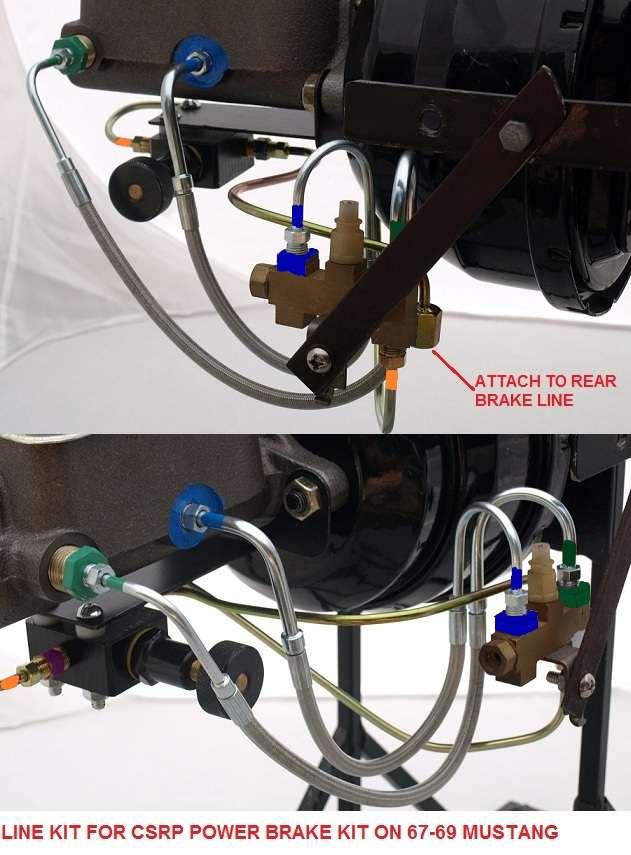
18 24. Connect the LKP.67 line kit as shown below. The images depict the installation of the under hood brake line kit components. 25. The flare nut at the end of the brake line coming from the rear brakes will now be fitted to the female fitting on the end of the line leading from the outlet of the proportioning valve. 26. Be sure to support the female hex fitting with an appropriate wrench when tightening the nut. Failure to do so WILL damage the fitting interface with the brake line). 27. Installations of the LKP.67 line kit onto a 70 Mustang will require a few adapters be installed on the distribution block (included with the appropriate kit). See the image below. F. Bleed the brakes 1. Follow the instructions included with the master cylinder or bleeding aid to bleed the brakes. 2. The task of brake bleeding is made easier if a pressure bleeder is used. The use of speed bleeder screws also makes the task easier. We do not recommend the vacuum bleeding method. 3. The brake pedal should be firm and high when the brakes are properly bled. 4. Be certain that the brake pedal is not adjusted so high as to prematurely actuate the booster. 18
19 19

20 G. Front wheel alignment and steering issues 1. Remount the wheels. 2. Remove any jack stands or jacks. 3. Place the car on level ground. 4. Center the steering wheel. 5. Adjust the tie rod sleeves to align the front wheels straight forward. 6. You may stretch a line parallel to the rear and front wheel. It should be possible to roughly set the Toe at 0 degree; that is, the wheels tracking straight forward. 7. Tighten the tie rod sleeve bolts. 8. Roughly adjust the caster and camber to 0 degrees. 9. The camber and caster are likely to be way out of specification. The pads and rotor need bedding-in before the brakes will work well. 10. Trailering to an alignment shop is recommended. Be very careful if you chose to drive the car to the alignment shop. 11. Have the front end aligned to specifications for toe (1/8 toe in), camber (0.0 to degree), and caster (+2.5 degree). 12. Remember to re-torque the sleeve bolts to ft-lb upon returning from the alignment shop. 20
21 H. Setting the adjustable proportioning valve APV The mechanical installation must be complete. 1. Turn the APV knob fully counter clockwise. 2. Find a level isolated location with normal road surface. A parking lot would be ideal. Ignore the common advice to use a wet or gravel surface. 3. Perform a series of normal stops, like at a stop sign. 4. Turn the APV s knob 1-2 turns clockwise in between each stop. 5. Repeat this process until the stop terminates in a little front end dive. This indicates that the front end has commenced braking first. 6. Some fine tuning may be indicated. I. Pad and rotor bedding-in. 1. Find a level isolated location with normal road surface. A large parking lot would be ideal. 2. Accelerate car to approximately 25 mph. 3. Apply brakes using light to moderate effort to reduce speed to approximately 5 mph (DO NOT stop, if possible). 4. Repeat this process at least 10 times allowing about 1/3 mile between cycles to cool the pads. 5. Avoid hard braking for the first 25 miles.\ The brake SWAP is complete. Carefully inspect all of the work and have a qualified mechanic inspect the work prior to operating the vehicle. IV. CSRP BRAKE SWAP FAQ Q. Does the kit come with a dual reservoir master cylinder? A. Yes, the kit comes with the proper dual reservoir master cylinder. Specify manual or power brakes when ordering. All applications come with an adjustable push rod. Q. Will I be required to bend and fabricate brake lines for the master cylinder? A. All CSRP kits come with a full under hood plumbing upgrade kit that includes a combination of braided stainless steel brake lines and steel hard lines that will make it easy to plumbing the master cylinder, proportioning valve and distribution block. 21
22 Q. What size are the rotors? A. The slotted rotors supplied with the kit are 11.2 diameter 5 lug type. Q. Can I use the outer tie rod ends from my car with the kit? A. Replacement outer tie rods are included. Reuse the inner tie rod arms. Q. Do I need to adapt my hard brake lines? A. The under the fender brake line will need to be modified on the SWAP.2 kits. SWAP.3 and 4 kits do not generally require brake line modification. Q. What does the kit include? A. The kit has all NEW parts including caliper brackets, splash shields, an adjustable proportioning valve, performance 11.2" SLOTTED rotors, corrosion protection coated calipers, semi-metallic pads, braided stainless steel brake hoses and new hose mounting brackets and hardware, dual reservoir master cylinder, an adjustable push rod, a complete under hood plumbing kit including braided stainless steel brake lines, bearings and seals, wheel hardware, caliper hardware, grade 8 attachment, blue and red thread locker, high temperature disc brake wheel bearing grease, and our renown installation guide via download. You need only bolt the kit, bleed the system, mount and align the wheels, adjust the proportioning valve, and the installation is complete. Q. My car has power steering. Will the kit work? A. Yes, a kit configuration is available for cars with power steering. Q. My Mustang has power brakes (or I want power brakes). Will the car s booster and master cylinder work with the SWAP kit, or will the master cylinder provided with the kit fit on my car s booster? A. No, the original booster/bracket system used on Mustangs is not compatible for use with a dual reservoir master cylinder. There is not enough space between this booster s face and the shock tower to mount one. This is because Ford located the mechanical clutch linkage in a place that interferes with the direct mounting of the booster to the firewall. In order to accommodate both manual and automatic transmission applications with one assembly type, a standoff bracket is employed. This bracket places the booster about 3 away from the firewall. In this position, it will not mechanically interfere with the operation of the clutch linkage. This works fine with the single reservoir master cylinder which is standard to the model, but will not allow the mounting of the dual reservoir master cylinder necessary for a safe modern brake system. 22
23 In any case, the original booster/bracket must be removed. This presents the kit installer with a couple of options. For automatic transmission equipped Mustang, CSRP offers a compatible MC/booster/ bracket system that will allow the use of the original pedal. One could also install the kit in manual brake mode. When purchasing the SWAP kit for these cars, the installer must specify a manual or a power brake kit. CSRP only offers power assist upgraded kits for Mustang and Cougar. On a manual transmission car with original power brakes, the installer must still remove the original booster/bracket, but has fewer practical options for power brakes. CSRP offers a power brake upgrade for this application only if the clutch linkage has been replace with a cable or hydraulic type that eliminates the interference. Otherwise, the user must install the system as manual brakes or find other options. Q. My Mustang has power brakes (or I want power brakes). Will the master cylinder provided work with the SWAP kit? A. A kit configured for can be provided with a power type master cylinder, proper under hood plumbing kit, and no booster at a minimal extra cost when specified. This master cylinder will work with all existing original equipment boosters present on cars. Those users wishing to upgrade their manual brakes from manual to power assist brakes can purchase our power brake assist upgrade kit for cars. This upgrade kit will fit all Mustang, regardless of transmission or engine type. We do not offer power brake upgrades for cars, or for other model cars aside from Mustang and Cougar. Q. Will the SWAP kit give me bumpsteer? What is bumpsteer? A. No, the SWAP kit installation does not affect the steering or suspension geometry. Bumpsteer is the change in steering output that occurs without driver input when the suspension moves. Basically, the wheels turn a little in response to going over bumps. This is a result of the fact that the radius of movement for the tie rods and the ball joints are different. Large deflections of the suspension cause different rates of movement of the control arms vs the tie rods causing a small steering input. This affect is most noticeable, if at all, in performance situations. All Mustangs and many other 60 s and 70 s cars are based on the Falcon chassis that Ford developed in the early 60 s. The suspension and steering gear for all of these cars are very similar. The suspension mounting configuration for the class, including most years of Falcon, Comet, Mustang, Cougar, Fairlane, Torino, Montego, Maverick, Granada, and Monarch remains the same from There were basically two steering geometries during the period. The Mustang and Falcon models have a slightly different geometry than the later 23
24 models. The later models have identical geometry. CSRP makes 2 series of spindles, so the spindles included in CSRP kits have correct steering and suspension geometries for the year model it is configured for. It is generally recognized the Falcon class chassis had poor suspension geometry, especially the early applications. It is generally agreed that making major modifications to the suspension, like using lowering coil springs, or cutting coil springs, or excessive lowering of the control arms, can exacerbate the inherent poor steering dynamics of the early Mustang (Falcon chassis). Q. Can I use my original wheels with the swap? A. SWAP.2, SWAP.3, and SWAP.4 kits require aftermarket 15 wheels with the OE 5 X 4.5 mounting pattern. Q. Will the swap work with my 6 cylinder car, and will I need to change the steering gear? A. One may install the kit if the cylinder car steering knuckles are replaced with the spindles included with the kit along with replacement of the steering linkage with V8 model type. SWAP.2, SWAP.3, and SWAP.4 kits include year model correct V8 type disc brake specific spindles. Q. Can I keep my 4 lug wheels with the swap? A. CSRP offers a 4 lug version of the SWAP.2 kit. It requires aftermarket 15 or larger wheels with OE 4 X 4.5 lug pattern. Q. How long does it take to do the SWAP? A. The removal of the old parts and installation of the new ones can easily be done in one weekend. Q. What does a proportioning valve do? A. A proportioning valve is a vital component of a disc brake system. It is a metering valve that controls the flow of brake fluid to the rear wheel cylinders. It functions to delay the full implementation of the rear brakes. Without the valve, the rear brakes would apply prematurely. An adjustable proportioning valve is the standard one included with the kit. It has an adjustment knob that functions much like a water faucet except that the flow of fluid is never stopped, just restricted. This valve is simple to plumb, but requires that the installer tune it by trial and error to give the desired rear braking performance (see installation procedure). Q. Will I need to buy anything else? 24
25 A. All parts are included. The cars existing spindles, distribution block, and terminal brake lines are reused. If you chose to replace the brake lines, only the two front terminal lines and the rear terminal line are needed. Drum or disc type are the same with these three lines. Q. Does the SWAP kit include instructions? A. The kit includes internet access to the installation guide. This guide goes through the history of the swap, and includes a complete installation guide. Q. Is the conversion safe? A. The system is based on an original Ford OEM design. The components are the best available. The installer must be reasonably proficient in mechanics. Brakes are a seriously necessary component of the safety system of your car. Have the new system inspected by a qualified mechanic before driving the car. CSRP will not accept the liability that the owner assumes when purchasing, installing, or using the SWAP. V. LEGAL NOTICE This document is only a guide. It in no way represents the ultimate authority on the subject presented. The user must exercise good judgment in relying on its content. It is incumbent upon the user to verify the guidance contained within. The seller of these parts and the authors of this guide provide the service of compiling parts that are generally recognized, when properly assembled, to provide a safe and effective front disc brake substitute for the antiquated drum brakes originally present on certain classic Fords from the 60 s and 70 s. The buyer must determine if is appropriate or prudent to undertake this front disc brake conversion using this kit and guide. The SWAP should only be undertaken by those who are competent in automotive brake system mechanics. The completed system must be installed or inspected by a certified mechanic, and any necessary adjustments made. The purchaser of the parts assumes all liability associated with their use. The seller does not accept liability associated with the use of these parts. The parts are warranted to be free of manufacturing defects for a period of 1 year from the time of purchase. This limited warranty is applied to replacement of the defective part(s) only. The warranty does not apply to any labor associated with installation of the part(s). Please see our terms of purchase located at our website The provisions contained there apply to this install and the parts herein. Thank you for purchasing the CSRP front disc brake conversion kit. Good luck and good motoring. 25
CLASSIC SERVICES RESTORATION PARTS
 CLASSIC SERVICES RESTORATION PARTS SWAP.3 Disc Brake Conversion Installation Guide For Mustang, Falcon, and Equivalent Applications Manual Brake 65-66 Mustang and Equivalents Third EDITION, REV A Please
CLASSIC SERVICES RESTORATION PARTS
 CLASSIC SERVICES RESTORATION PARTS SWAP.4 Disc Brake Conversion Installation Guide For Mustang, Falcon, and Equivalent Applications Manual Brake 65-66 Mustang and Equivalents 1st EDITION, REV A Please
CLASSIC SERVICES RESTORATION PARTS
 CLASSIC SERVICES RESTORATION PARTS SWAP.2 Disc Brake Conversion Installation Guide For Mustang, Falcon, and Equivalent Applications Manual Brake 65-66 Mustang and Equivalents Third EDITION, REV E Please
CLASSIC SERVICES RESTORATION PARTS
 CLASSIC SERVICES RESTORATION PARTS Installation Guide for the SWAP.1 FORD/KH 4 Piston Caliper Type Front Disc Brake Conversion for Mustang, Falcon, and Equivalent Applications Manual brake 65-66 Mustang
The Granada Front Disc Brake Swap Installation Guide For Mustang, Falcon, and Equivalent Applications
 CLASSIC SERVICES RESTORATION PARTS The Granada Front Disc Brake Swap Installation Guide For Mustang, Falcon, and Equivalent Applications SECOND EDITION The Granada swap contents I. INTRODUCTION Why use
INSTALLATION INSTRUCTIONS
 INSTALLATION INSTRUCTIONS FRONT DISC BRAKE CONVERSION KITS: A132-1, A133, A133-1 A134, A134-1 1968-73 MUSTANG/FORD Thank you for choosing STAINLESS STEEL BRAKES CORPORATION for your braking needs. Please
Installation Instructions
 Preparing your vehicle to install your brake system upgrade 1. Rack the vehicle. 2. If you don t have a rack, then you must take extra safety precautions. 3. Choose a firmly packed and level ground to
INSTALLATION INSTRUCTIONS
 INSTALLATION INSTRUCTIONS PERFORMANCE AT THE WHEELS KIT W120-22, W120-23 1964 1/2-69 MUSTANG Thank you for choosing STAINLESS STEEL BRAKES CORPORATION for your braking needs. Pleases take the time to read
INSTALLATION INSTRUCTIONS
 INSTALLATION INSTRUCTIONS DISC BRAKE CONVERSION KITS A121-1, A121-2, A121-3, A121-4 1967-69 Ford & Mercury Thank you for choosing STAINLESS STEEL BRAKES CORPORATION for your braking needs. Pleases take
INSTALLATION INSTRUCTIONS
 INSTALLATION INSTRUCTIONS DISC BRAKE CONVERSION KITS A120-4 & A120-5 1964-1/2-66 Ford & Mercury Thank you for choosing STAINLESS STEEL BRAKES CORPORATION for your braking needs. Pleases take the time to
INSTALLATION INSTRUCTIONS
 INSTALLATION INSTRUCTIONS PERFORMANCE AT THE WHEELS KITS W156-6 & W156-7 1965-74 MOPAR B & E BODY Thank you for choosing STAINLESS STEEL BRAKES CORPORATION for your braking needs. Pleases take the time
1969 Camaro. Concourse Style Disc Brake Conversion Kit Instllation Instructions
 Concourse Style Disc Brake Conversion Kit Instllation Instructions 1969 Camaro (1970 Chevelle Kit Shown) This document contains our regular disc brake conversion instructions with the addition of GM assembly
A/F/X Body GM Installation Instructions Manual Disc Conversion
 A/F/X Body GM Installation Instructions Manual Disc Conversion 64-72 A Body / 67-69 F Body / 62-74 X Body DBMC09 & PVK71 pictured above (Booster, master & valve setups may vary by upgrades selected) Your
60 76 A Body Mopar Power Disc Conversion Installation Instructions
 62-72 B & E BodyMopar 60 76 A Body Mopar Power Disc Conversion Installation Instructions Special A-Body only parts shown below (In addition to parts above for A-Body cars, part # MDC66DC & MDC46DC) Your
A/F/X Body GM Installation Instructions
 A/F/X Body GM Installation Instructions Power Disc Conversion 64-72 A Body / 67-69 F Body / 68-74 X Body 9 slimline booster pictured Your new disc brake conversion kit can be bolted up with standard hand
INSTALLATION INSTRUCTIONS
 INSTALLATION INSTRUCTIONS DISC BRAKE CONVERSION KIT A120-20, A120-21 1964 1 /2-66 Ford & Mercury Thank you for choosing STAINLESS STEEL BRAKES CORPORATION for your braking needs. Pleases take the time
A/F/X Body GM Installation Instructions Manual Disc Conversion
 A/F/X Body GM Installation Instructions Manual Disc Conversion 64-72 A Body / 67-69 F Body / 62-74 X Body DBMC09 & PVK71 pictured above (Booster, master & valve setups may vary by upgrades selected) Your
INSTALLATION GUIDE TCP SPND MUSTANG SPINDLES WITH GRANADA OUTER TIE-ROD TAPER
 READ ALL INSTRUCTIONS COMPLETELY AND THOROUGHLY UNDERSTAND THEM BEFORE DOING ANYTHING. CALL TOTAL CONTROL PRODUCTS TECH SUPPORT (916) 388-0288 IF YOU NEED ASSISTANCE. INSTALLATION GUIDE TCP SPND-04 70-73
INSTALLATION INSTRUCTIONS
 INSTALLATION INSTRUCTIONS FRONT DISC BRAKE CONVERSION KIT A129-2 1959-64 Full Size Chevrolet Car and FRONT DISC BRAKE CONVERSION KITS A129-3 & A129-4 1965-68 Full Size Chevrolet Car Thank you for choosing
DISC BRAKE/DUAL MASTER CYLINDER CONVERSION. Tools, Equipment and Supplies Needed:
 Please take the time to read the enclosed instructions carefully. If you have any questions, call our Product Assistance personnel for clarification. It is important to note that these instructions contain
DBK FULL-SIZE CHEVY DISC BRAKE conversion KIT
 DBK5964 1959-1964 FULL-SIZE CHEVY DISC BRAKE conversion KIT impala, bel air, biscayne Installation Instructions does not fit 14" rims must ust 15" or larger for this kit to be installed correctly on your
INSTALLATION INSTRUCTIONS
 INSTALLATION INSTRUCTIONS POWER FRONT DISC CONVERSION KIT A126-7 1963-66 CHEVY C10 PICKUP NON-POWER FRONT DISC CONVERSION KIT A126-8 1963-72 CHEVY C10 PICKUP Thank you for choosing STAINLESS STEEL BRAKES
INSTALLATION INSTRUCTIONS
 INSTALLATION INSTRUCTIONS BIG ROTOR / CALIPER RELOCATION REAR KIT SUM-BK1423 1999-2009 GM 1/2 Ton Trucks & SUVs Thank you for choosing SUMMIT RACING for your braking needs. Pleases take the time to read
55-64 Full Size Chevy
 55-64 Full Size Chevy Installation Instructions Power Disc Conversion 9 slimline booster pictured Your new disc brake conversion kit can be bolted up with standard hand tools. The only tools you may not
INSTALLATION INSTRUCTIONS
 INSTALLATION INSTRUCTIONS BIG ROTOR / CALIPER RELOCATION FRONT KITS SUM-BK1422, BK1423, BK1424 1999-2006 GM 1/2 Ton Trucks & SUVs Thank you for choosing SUMMIT RACING for your braking needs. Pleases take
Tools, Equipment and Supplies Needed:
 153-162 DISC BRAKE/DUAL MASTER CYLINDER CONVERSION Please take the time to read the enclosed instructions carefully. If you have any questions, call our Product Assistance personnel for clarifi cation.
55-64 Full Size Chevy Installation Instructions Standard Disc Conversion
 55-64 Full Size Chevy Installation Instructions Standard Disc Conversion DBMC09, PV71 & PVB71 Pictured (Booster, master cylinder & valve setups may vary by upgrades selected) Your new disc brake conversion
INSTALLATION INSTRUCTIONS
 INSTALLATION INSTRUCTIONS FRONT DISC BRAKE CONVERSION KITS SUM-BK1200, SUM-BK1201, SUM-BK1202, SUM-BK1203 1964-72 A-BODY 1967-69 F-BODY 1962-74 X-BODY (NOTE: 62-64 X-BODY REQUIRES 5-LUG STEERING ARMS)
INSTALLATION INSTRUCTIONS
 INSTALLATION INSTRUCTIONS REAR CONVERSION KIT A111-2 (FORD 8" & 9" SMALL BEARING) & REAR CONVERSION KIT A111-3 (FORD 9 TORINO) Thank you for choosing STAINLESS STEEL BRAKES CORPORATION for your braking
FORD FAIRLANE Booster Conversion Kit ( TORINO, RANCHERO )
") 1966-1971 FORD FAIRLANE Booster Conversion Kit ( TORINO, RANCHERO ) F R Unboxing your kit: 1. Remove new booster, bracket assembly and master cylinder from their boxes and inspect the parts. 2. New boosters
1966-1971 FORD FAIRLANE Booster Conversion Kit ( TORINO, RANCHERO ) F R Unboxing your kit: 1. Remove new booster, bracket assembly and master cylinder from their boxes and inspect the parts. 2. New boosters
INSTALLATION INSTRUCTIONS
 INSTALLATION INSTRUCTIONS INSTRUCTION FOR ASSEMBLY OF JEEP CJ SERIES W/AMC 20 REAR AXLES, 5 x 5-1/2" BOLT CIRCLE WITH A130-1 FULL FLOATING AXLE OR A130-2 (1 PIECE AXLE) Thank you for choosing STAINLESS
INSTALLATION INSTRUCTIONS
 INSTALLATION INSTRUCTIONS Disc Brake Spindle Kit SUM-BKA2447 1964-72 A-BODY 1967-69 F-BODY 1968-74 X-BODY Thank you for choosing SUMMIT RACING for your braking needs. Please take the time to read and carefully
A /F/X Body Instruction Packet Rear Disc Conversion
 A /F/X Body Instruction Packet Rear Disc Conversion 64-72 A Body / 67-81 F Body / 62-74 X Body This kit is for axles with a 3 1/8 spread center to center on the top two bolt holes (pictured left). Rotor
APPLIED GMC / 1 (800) KATO RD. FREMONT, CA GMC ALL DISC BRAKE KIT
 KATO RD. FREMONT, CA GMC ALL DISC BRAKE KIT") APPLIED GMC 510-440-1101 / 1 (800) 752-7502 47626 KATO RD. FREMONT, CA 94538 GMC ALL DISC BRAKE KIT Shade Tree Mechanic's Guide to Disc Brake Upgrade Installation Instructions Written by: Edited by: Randy
APPLIED GMC 510-440-1101 / 1 (800) 752-7502 47626 KATO RD. FREMONT, CA 94538 GMC ALL DISC BRAKE KIT Shade Tree Mechanic's Guide to Disc Brake Upgrade Installation Instructions Written by: Edited by: Randy
Installation Instructions
 Installation Instructions Rear Disc Brake Conversion Kit Item # RC4001, RC4001X Applications: Mopar 7.25, 8.25, 9.25 Axles Thank you for choosing Leed Brakes for your automotive product needs. Before you
INSTALLATION INSTRUCTIONS
 INSTALLATION INSTRUCTIONS REAR DRUM TO DISC BRAKE CONVERSION KIT A130 JEEP CJ SERIES W/AMC-20 REAR AXLES AND 5 x 5-1/2" BOLT CIRCLE Thank you for choosing STAINLESS STEEL BRAKES CORPORATION for your braking
Installation Instructions
 Installation Instructions Rear Disc Brake Conversion Kit Item # RC2001, RC2001X Applications: Mopar 8-3/4 & 9-3/4 Rear Axles Thank you for choosing Leed Brakes for your automotive product needs. Before
INSTALLATION INSTRUCTIONS
 INSTALLATION INSTRUCTIONS REAR DISC BRAKE CONVERSION KIT A158 1994-97 Dodge Ram 1500 (2WD & 4WD) and REAR DISC BRAKE CONVERSION KIT A158-1 1998-01 Dodge Ram 1500 (2WD & 4WD) Thank you for choosing STAINLESS
55-64 Full Size GM (Impala, Bel Air, etc.) This kit is for axles with a 3 3/8 spread center to center on the top two bolt holes (pictured left).
 This kit is for axles with a 3 3/8 spread center to center on the top two bolt holes (pictured left).") SUM-BK1624A Full Size GM Installation Instructions Rear Disc Conversion 55-64 Full Size GM (Impala, Bel Air, etc.) This kit is for axles with a 3 3/8 spread center to center on the top two bolt holes (pictured
SUM-BK1624A Full Size GM Installation Instructions Rear Disc Conversion 55-64 Full Size GM (Impala, Bel Air, etc.) This kit is for axles with a 3 3/8 spread center to center on the top two bolt holes (pictured
INSTALLATION INSTRUCTIONS
 INSTALLATION INSTRUCTIONS REAR DISC CONVERSION KIT A136-1 1976-86 AMC 20 AXLES WITH WARN FULL FLOATING AXLE CONVERSION Thank you for choosing STAINLESS STEEL BRAKES CORPORATION for your braking needs.
BRAKE SYSTEM Nissan 240SX DESCRIPTION BRAKE BLEEDING * PLEASE READ FIRST * BLEEDING PROCEDURES ADJUSTMENTS BRAKE PEDAL HEIGHT SPECS TABLE
 BRAKE SYSTEM 1990 Nissan 240SX 1990 BRAKE SYSTEMS Nissan Disc & Drum Axxess, Maxima, Pathfinder, Pickup, Pulsar NX, Sentra, Stanza, 240SX, 300ZX DESCRIPTION All brake systems are hydraulically operated
RHINO SUSPENSION SYSTEM INSTALLATION INSTRUCTIONS
 PARTS INCLUDED: 2 FRONT UPPER A-ARMS 2 FRONT LOWER A-ARMS 2 UNI-BALL JOINTS 2 UNI-BALL JOINT STUDS 2 UNI-BALL JOINT CAPS 2 RETAINING RINGS 1 FRONT SHOCK ASSEM. 2 DELRON STEERING STOPS 2 SHOCK MOUNT SPACERS
Installation Instructions
 Installation Instructions Rear Disc Brake Conversion Kit Item # RC1001, RC1001X Applications: 64-72 A-body, 67 F-Body, 63-67 X-body with Non Staggered Shocks Thank you for choosing GPS Auto for your automotive
INSTALLATION INSTRUCTIONS
 INSTALLATION INSTRUCTIONS REAR DISC BRAKE CONVERSION KITS A112, A112-1 & A112-93 1979-93 FORD MUSTANG with 7.5" & 8.8" AXLES Thank you for choosing STAINLESS STEEL BRAKES CORPORATION for your braking needs.
This file is available for free download at
 This file is available for free download at http://www.iluvmyrx7.com This file is fully text-searchable select Edit and Find and type in what you re looking for. This file is intended more for online viewing
Chevy Nova Pro-Touring Front Suspension Installation Instructions
 1962-1967 Chevy Nova Pro-Touring Front Suspension Installation Instructions 1-800-984-6259 www.totalcostinvolved.com 1 Pro-Touring Clip A-Arm Assembly Sway Bar Assembly Fender Panel Kit 8 7/16-20 * 1 ¼
INSTALLATION INSTRUCTION 88581
 INSTALLATION INSTRUCTION 88581 FOR RANCHO SUSPENSION SYSTEM RS6581B: DODGE RAM READ ALL INSTRUCTIONS THOROUGHLY FROM START TO FINISH BEFORE BEGINNING INSTALLATION Rev C IMPORTANT NOTES! WARNING: This suspension
SCION tc BIG BRAKE KIT Section I - Installation Preparation
 SCION tc 2005- BIG BRAKE KIT Section I - Installation Preparation Part Number: PTR09-21080 Kit Contents Item # Quantity Reqd. Description 1 1 Brake Rotor, LH Front 2 1 Brake Rotor, RH Front 3 1 Brake Caliper
INSTALLATION INSTRUCTIONS
 INSTALLATION INSTRUCTIONS FRONT BIG BRAKE CONVERSION KIT A112-5 1987-93 FORD MUSTANG Thank you for choosing STAINLESS STEEL BRAKES CORPORATION for your braking needs. Pleases take the time to read and
INSTALLATION INSTRUCTIONS
 INSTALLATION INSTRUCTIONS REAR DISC BRAKE CONVERSION KIT A126-1 1973-87 CHEVROLET 1/2 TON 2WD Thank you for choosing STAINLESS STEEL BRAKES CORPORATION for your braking needs. Pleases take the time to
Mopar 8 3/4 & 9 3/4 (Dana) Installation Instructions Rear Disc Conversion
 Installation Instructions Rear Disc Conversion") Mopar 8 3/4 & 9 3/4 (Dana) Installation Instructions Rear Disc Conversion This kit is for either Mopar 8 ¾ or Mopar 9 ¾ (Dana). This kit is designed to work with axles with either GM 5 x 4.75 Bolt Pattern
Mopar 8 3/4 & 9 3/4 (Dana) Installation Instructions Rear Disc Conversion This kit is for either Mopar 8 ¾ or Mopar 9 ¾ (Dana). This kit is designed to work with axles with either GM 5 x 4.75 Bolt Pattern
INSTALLATION INSTRUCTIONS
 INSTALLATION INSTRUCTIONS REAR DISC CONVERSION KIT A126-2 1988-98 C1500 2WD 10" REAR DRUM Thank you for choosing STAINLESS STEEL BRAKES CORPORATION for your braking needs. Pleases take the time to read
INSTALLATION INSTRUCTIONS
 INSTALLATION INSTRUCTIONS REAR DISC CONVERSION KIT A128-4 1997-2004 JEEP WRANGLER (TJ) WITH DANA 44 AXLES (non-abs) Thank you for choosing STAINLESS STEEL BRAKES for your braking needs. Pleases take the
60-65 Falcon, Comet & Ranchero Coil Spring IFS
 60-65 Falcon, 62-65 Comet & 62-65 Ranchero Coil Spring IFS All engine installations with this front end will require a rear sump oil pan. 289-302 Small Block Ford Motors Milodon rear sump pan holds 7 quarts
Ford 8, 9 Small Bearing Installation Instructions Rear Disc Conversion
 Ford 8, 9 Small Bearing Installation Instructions Rear Disc Conversion This kit is for Ford 9 rear axles with the small (2.835 ) style bearing and Ford 8 rear ends. This kit is designed to work with axles
INSTALLATION INSTRUCTIONS
 INSTALLATION INSTRUCTIONS REAR DISC BRAKE CONVERSION KIT A125-3 1965-72 GM A-BODY 10 & 12 BOLT AXLES Thank you for choosing STAINLESS STEEL BRAKES CORPORATION for your braking needs. Pleases take the time
Commander SUSPENSION SYSTEM INSTALLATION INSTRUCTIONS
 PARTS INCLUDED: 2 - FRONT UPPER A-ARMS 2 - FRONT LOWER A-ARMS 4 - COTTER PINS 2-12MM JAM NUTS 2 - TIE ROD EXTENDERS 8- FLANGED DELRON BUSHINGS 4- DELRON CASTER SPACERS 6 - GREASE FITTINGS 3 - BEARING REMOVAL
INSTALLATION INSTRUCTIONS
 INSTALLATION INSTRUCTIONS FRONT DISC BRAKE CONVERSION KITS A148-9 & A148-15 1949-54 Chevy Trucks Thank you for choosing STAINLESS STEEL BRAKES CORPORATION for your braking needs. Please take the time to
INSTALLATION INSTRUCTIONS
 INSTALLATION INSTRUCTIONS 2005-2012 Nissan Xterra/Frontier / Pathfinder PART NUMBERS: NP17500, NP17525, NP17550 FRONTIER PARTS & CORRESPONDING HARDWARE LIST XTERRA PATHFINDER ABOVE LISTED 1/2 Metal Lock
1984 Dodge W250 PICKUP
 1984 Dodge W250 PICKUP Submodel: Engine Type: V8 Liters: 5.2 Fuel Delivery: CARB Fuel: GAS Dana 44 MODELS THROUGH 1984 2. Raise and safely support the vehicle, then remove the wheel hub and bearings as
NEW BRAKE INSTALLATION. Let us show you how a
 Tech Article From Newsletter 17.2-2nd Quarter of 2011 NEW BRAKE INSTALLATION Let us show you how a Big Brake Install is easier than you think!! So, you have a 572 (or a hot 383) in your shoebox... you
Slide the billet aluminum cap over the bushing and secure with the 3/8-16 x 2 1/2 socket head allen and locknuts provided.
 Slide the billet aluminum cap over the bushing and secure with the 3/8-16 x 2 1/2 socket head allen and locknuts provided. Put the urethane bushings into the upper antiroll-bar-link eyebolt. Coat the bushings
INSTALLATION INSTRUCTION 88094
 INSTALLATION INSTRUCTION 88094 FOR RANCHO SUSPENSION SYSTEM RS6594B 4WD & 2WD NISSAN TITAN READ ALL INSTRUCTIONS THOROUGHLY FROM START TO FINISH BEFORE BEGINNING INSTALLATION Rev D IMPORTANT NOTES! WARNING:
ASSEMBLY INSTRUCTIONS
 ASSEMBLY INSTRUCTIONS FOR FORGED SUPERLITE BIG BRAKE FRONT HUB KIT WITH 3.00 DIAMETER VENTED ROTOR 968-969 FORD MUSTANG (DISC BRAKE SPINDLE ONLY) PART NUMBER GROUP 0-950 WARNING INSTALLATION OF THIS KIT
INSTALLATION INSTRUCTIONS
 INSTALLATION INSTRUCTIONS REAR DISC CONVERSION KIT SUM-BK1414-X 1997-2004 JEEP WRANGLER (TJ) WITH DANA 44 AXLES (non-abs) Thank you for choosing SUMMIT RACING for your braking needs. Pleases take the time
INSTALLATION INSTRUCTIONS
 INSTALLATION INSTRUCTIONS REAR DISC BRAKE CONVERSION KIT A125-2 1955-70 FULL SIZE CHEVROLET Thank you for choosing STAINLESS STEEL BRAKES CORPORATION for your braking needs. Pleases take the time to read
INSTALLATION INSTRUCTIONS
 INSTALLATION INSTRUCTIONS R1 REAR DRUM TO DISC BRAKE CONVERSION KIT A130-3 JEEP CJ SERIES W/AMC-20 REAR AXLES AND 5 x 5-1/2" BOLT CIRCLE Thank you for choosing STAINLESS STEEL BRAKES CORPORATION for your
INSTALLATION INSTRUCTIONS
 INSTALLATION INSTRUCTIONS INSTALLATION INSTRUCTIONS FOR A136 REAR DRUM TO DISC BRAKE CONVERSION KIT for 1970-75 Jeep, CJ SERIES with Dana 44 flanged axle Thank you for choosing STAINLESS STEEL BRAKES CORPORATION
A/F/X Body GM Installation Instructions Power Disc Conversion
 A/F/X Body GM Installation Instructions Power Disc Conversion 64-72 A Body / 67-69 F Body / 62-74 X Body DBMC09, PVK71 & RPB1001 pictured above (Booster, master & valve setups may vary by upgrades selected)
INSTALLATION INSTRUCTIONS
 INSTALLATION INSTRUCTIONS FX4 ELITE REAR DISC CONVERSION KITS WITH INTERNAL PARKING BRAKE A110-14, A111-25, A111-29 for FORD 8" & 9" REAR ENDS Thank you for choosing STAINLESS STEEL BRAKES CORPORATION
First, check and record the camber and caster readings, they will be adjusted later.
 First, check and record the camber and caster readings, they will be adjusted later. The caliper-mounting bosses are machined perpendicular to the spindle so they are an excellent place for the level.
INSTALLATION INSTRUCTIONS
 INSTALLATION INSTRUCTIONS PERFORMANCE AT THE WHEELS KIT W155-5 CHRYSLER 8 3 /4" & 9 3 /4" REAR AXLES Thank you for choosing STAINLESS STEEL BRAKES CORPORATION for your braking needs. Please take the time
ASSEMBLY INSTRUCTIONS
 ASSEMBLY INSTRUCTIONS FOR DYNALITE PRO SERIES FRONT HUB KIT WITH.75 DIAMETER VENTED ROTOR 970-973 FORD MUSTANG (DRUM / DISC SPINDLE) PART NUMBER GROUP 0-905 WARNING INSTALLATION OF THIS KIT SHOULD ONLY
EGR Performance Brakes Assembly Instructions DODGE DANA 70 '87 - '93 (Will not fit stock sized dual rear wheels)
") EGR Performance Brakes Assembly Instructions DODGE DANA 70 '87 - '93 (Will not fit stock sized dual rear wheels) Got Brakes? Parts List (2) Vented Rotors (2) Multi hole Cable Mount & L Brkt (2) Axle Tube
EGR Performance Brakes Assembly Instructions DODGE DANA 70 '87 - '93 (Will not fit stock sized dual rear wheels) Got Brakes? Parts List (2) Vented Rotors (2) Multi hole Cable Mount & L Brkt (2) Axle Tube
INSTALLATION INSTRUCTIONS
 INSTALLATION INSTRUCTIONS REAR CONVERSION KITS SUM-BK1326-X, SUM-BK1326-99904, SUM-BK1327-X, SUM-BK1327-99904, SUM-BK1328-X, SUM-BK1328-99904 FORD 8 and 9 AXLES WITH GM & FORD BOLT PATTERN Thank you for
ASSEMBLY INSTRUCTIONS FOR PART NUMBER GROUP
 ASSEMBLY INSTRUCTIONS FOR DYNAPRO 6 BIG BRAKE FRONT HAT KIT, 1.19 DIAMETER VENTED ROTOR 1990-005 ACURA/CIVIC ( LUG) 000-003 CIVIC SI ( LUG) 007 - PRESENT HONDA FIT FOR FACTORY 6 mm DISC SPINDLE PART NUMBER
SUM Chevy Truck frame mount booster kit
 SUM-760211 1955-1959 Chevy Truck frame mount booster kit Unboxing your kit: 1. Remove new booster, bracket assembly and master cylinder from their boxes and inspect the parts. 2. New boosters come with
general booster conversion kit instructions
 general booster conversion kit instructions your kit may look slightly different than above instructions are general and work for many builds Unboxing your kit: 1. Remove new booster, bracket assembly
99-04 GT. Hellion Power Systems Mustang GT Kit Instructions
 Hellion Power Systems 99-04 Mustang GT Kit Instructions Part 1 Hellion recommends that the front suspension system be installed either by trained professionals or by 5.Remove rack bolts K-Member Installation
INSTALLATION INSTRUCTIONS
 INSTALLATION INSTRUCTIONS REAR DISC BRAKE CONVERSION KIT A126-3 1988-98 CHEVY K1500 4WD 10" DRUMS Thank you for choosing STAINLESS STEEL BRAKES CORPORATION for your braking needs. Pleases take the time
Complete Front End Suspension Rebuild, Ñ Part 1, Tear Down
 Complete Front End Suspension Rebuild, 1955-57Ñ Part 1, Tear Down by Randy Irwin There is much more to performance than pure horsepower. Great performance comes from control and Classic Chevy InternationalÕs
Installation Instructions
 99-04 Suzuki Sidekick 2 Inch Budget Lift Kit Also fits 99-04 Tracker, Vitara, Grand Vitara or XL-7 Instructions Include:! SKU# KSP-BLKV Basic Kit!!!! SKU# KSP-C2BLKV-RS Basic Kit W/Rear Shocks!!!! SKU#
Installation Notes: #86000-R Race Series +3.5 L/T Kit
 159 North Maple St. Unit J, CORONA CA 92880 P. 951-737-9682 F. 951-737-9006 WWW.CHAOSFAB.COM Installation Notes: #86000-R Race Series +3.5 L/T Kit Factory manual is recommended for removal and re-installation
in the 1970 Ford Car Shop Manual, Volume One, Chassis. It is strongly recommended that a Shop Manual be obtained and followed.
 1970 Trans Am Mustang Front Disk brake instructions 1. The installation of this kit follows the standard procedures described in the 1970 Ford Car Shop Manual, Volume One, Chassis. It is strongly recommended
INSTALLATION GUIDE. TCP STRD-07 Adjustable Strut Rods
 READ ALL INSTRUCTIONS COMPLETELY AND THOROUGHLY UNDERSTAND THEM BEFORE DOING ANYTHING. CALL TOTAL CONTROL PRODUCTS TECH SUPPORT (916) 388-0288 IF YOU NEED ASSISTANCE. INSTALLATION GUIDE TCP STRD-07 Adjustable
TCP UCA-07 Coil-Spring Upper Control Arm with Dropped Pivot Shaft Mustang
 READ ALL INSTRUCTIONS COMPLETELY AND THOROUGHLY UNDERSTAND THEM BEFORE DOING ANYTHING. CALL TOTAL CONTROL PRODUCTS TECH SUPPORT (916) 388-0288 IF YOU NEED ASSISTANCE. INSTALLATION GUIDE TCP UCA-07 Coil-Spring
INSTALLATION INSTRUCTIONS R1 REAR CONVERSION KIT
 INSTALLATION INSTRUCTIONS R1 REAR CONVERSION KIT INSTRUCTION FOR ASSEMBLY OF JEEP CJ SERIES W/AMC 20 REAR AXLES, 5 x 5-1/2" BOLT CIRCLE WITH A130-4 FULL FLOATING AXLE OR A130-5 (1 PIECE AXLE) Thank you
INSTALLATION INSTRUCTIONS
 INSTALLATION INSTRUCTIONS REAR DISC BRAKE CONVERSION KITS SUM-BK1329-X, SUM-BK1329-99904, SUM-BK1330-X, SUM-BK1330-99904 CHRYSLER 8 3 /4", 9 3 /4" and 2-PIECE REAR AXLES Thank you for choosing SUMMIT RACING
ASSEMBLY INSTRUCTIONS FOR DYNALITE DRAG RACE FRONT HUB KIT WITH DIAMETER SOLID ROTOR PINTO / MUSTANG II
 ASSEMBLY INSTRUCTIONS FOR DYNALITE DRAG RACE FRONT HUB KIT WITH 0.75 DIAMETER SOLID ROTOR 97-978 PINTO / MUSTANG II (FIVE LUG CONFIGURATION ONLY)* PART NUMBER GROUP 0-03-B DISC BRAKES SHOULD ONLY BE INSTALLED
INSTALLATION INSTRUCTION 88148
 INSTALLATION INSTRUCTION 88148 Rev C For Rancho Suspension Systems RS6548, RS6549 & RS6550: GM 2500HD, 2500, and 1500HD Trucks READ ALL INSTRUCTIONS THOROUGHLY FROM START TO FINISH BEFORE BEGINNING INSTALLATION
jegs.com
 Installation Instructions for 630040 & 630050 A-Body 2 Drop Spindle Disc Brake Kit Instructions * High performance kit shown. Regular kit has plain rotors & hoses. WARNING Proper operation of your brakes
REMOVAL & INSTALLATION
 REMOVAL & INSTALLATION FRONT DISC BRAKE PADS 1. Raise and support front of vehicle. Remove wheels. Remove caliper bolt and brakeline bracket bolts. Pivot caliper aside. Remove pads and pad shim. Remove
INSTALLATION INSTRUCTIONS
 INSTALLATION INSTRUCTIONS REAR DISC CONVERSION KIT A128 1990-1995 JEEP WRANGLER (YJ) WITH DANA 35 AXLES (non-abs) Thank you for choosing STAINLESS STEEL BRAKES CORPORATION for your braking needs. Pleases
M-2300-T 6-Piston Mustang Brake Kit INSTALLATION INSTRUCTIONS
 Please visit www.fordracingparts.com for the most current instruction information!!! PLEASE READ ALL OF THE FOLLOWING INSTRUCTIONS CAREFULLY PRIOR TO INSTALLATION. AT ANY TIME YOU DO NOT UNDERSTAND THE
Signature Series A/F/X Body GM Installation Instructions Power Disc Conversion
 Signature Series A/F/X Body GM Installation Instructions Power Disc Conversion 64-72 A Body / 67-69 F Body / 62-74 X Body Your new disc brake conversion kit can be bolted up with standard hand tools. The
This file is available for free download at
 This file is available for free download at http://www.iluvmyrx7.com This file is fully text-searchable select Edit and Find and type in what you re looking for. This file is intended more for online viewing
Front Suspension Redo
 Front Suspension Redo Message: First, thanks to all the previous posters for guidance in my doing the suspension. As thanks, here s the updated document for doing the front suspension. Procedure: While
INSTALLATION INSTRUCTIONS
 INSTALLATION INSTRUCTIONS COMP. R AND COMP. S QUICK CHANGE KITS A200, A200-1 Thank you for choosing STAINLESS STEEL BRAKES CORPORATION for your braking needs. Pleases take the time to read and carefully
Converting a Series Land Rover to front wheel disc brakes using the kit made by Torrel Industries Ltd,
 Converting a Series Land Rover to front wheel disc brakes using the kit made by Torrel Industries Ltd, Torrel Industries ltd Series Land Rover front brake conversion kit: Difficulty - Low Except for one
2011+ Adjustable Tie-rod Ends (Mm5TR-2)
") 3430 Sacramento Dr., Unit D San Luis Obispo, CA 93401 Telephone: 805/544-8748 Fax: 805/544-8645 www.maximummotorsports.com 2011+ Adjustable Tie-rod Ends (Mm5TR-2) Instructions 1. Set the parking brake
3430 Sacramento Dr., Unit D San Luis Obispo, CA 93401 Telephone: 805/544-8748 Fax: 805/544-8645 www.maximummotorsports.com 2011+ Adjustable Tie-rod Ends (Mm5TR-2) Instructions 1. Set the parking brake