SERVICE MANUAL RA SERIES INDEX DRIVES MODELS 400RA, 401RA, 512RA & 662RA
|
|
|
- Jasmin Parsons
- 6 years ago
- Views:
Transcription
1 SERVICE MANUAL RA SERIES INDEX DRIVES MODELS 400RA, 401RA, 512RA & 662RA The Driving Force in Automation WARNING This is a controlled document. It is your responsibility to deliver this information to the end user of the CAMCO/FERGUSON product. Failure to deliver this could result in your liability for injury to the user or damage to the machine. For copies of this manual call your Customer Service Representative
2 TABLE OF CONTENTS INTRODUCTION... 2 WARNINGS AND CAUTIONS... 2 OIL SEAL REMOVAL... 2 SPARE PARTS KIT... 2 DISASSEMBLY... 3 REMOVAL OF BEARINGS... 4 INPUT SHAFT / CAM REMOVAL... 4 PRIOR TO REASSEMBLY... 4 ASSEMBLY... 4 ASSEMBLING INPUT SHAFT... 5 ASSEMBLY OF OUTPUT SHAFT... 5 SETTING CAM... 6 HOW TO ORDER PARTS... 7 EXPLODED PARTS DRAWING... 8 PARTS LIST... 9
3 INTRODUCTION This service manual pertains to the disassembly and assembly of CAMCO s RA Series Index Drive MODELS 400RA, 401RA,512RA, & 662RA. The manual is to be used in conjunction with the General Service Manual which describes the lubrication and general maintenance of CAMCO Index Drives. An exploded view of your specific Index Drive is included in this manual. Also included is a complete Bill of Materials for your convenience in identifying and ordering spare or replacement parts. Some users of Index Drives have the facilities and trained personnel to accomplish service repair. You must determine the extent to which intricate servicing should be done in your own facility. When in doubt, CAMCO recommends that CAMCO trained servicemen make the repairs. WARNINGS AND CAUTIONS Statements in this manual preceded by the words WARNING or CAUTION and printed in italics are very important. We recommend you take special notice of these during service or repair. WARNING Means there is the possibility of personal injury to yourself or others. CAUTION Means there is the possibility of damage to the CAMCO unit. OIL SEAL REMOVAL The only repair possible without disassembly of the indexer is replacement of oil seals. To remove oil seals, drill a number of holes into the case of the seal. The seal may then be removed with a pointed tool. Be sure to remove all metallic chips created during the drilling of removal holes. A new seal may be installed as outlined in the Oil Seal Installation Recommendations section of the General Service Manual. SPARE PARTS KIT CAMCO offers a Spare Parts Kit for all CAMCO index drive models CAMCO builds. These kits include oil seals, bearings, shims and cam followers. These are components that will most likely require replacement during repair of your index drive. CAMCO recommends a Spare Parts Kit be purchased and kept on hand prior to any disassembly of your CAMCO drive. A compete list of components supplied in the Spare Parts Kit can be found in the parts list located in the rear of this manual. The asterisk behind the item number indicates those parts supplied with the Spare Parts Kit. BEFORE STARTING Before starting disassembly of your CAMCO unit you should read and review the following instructions. These provide important information on parts and procedures necessary to successfully complete your repair. Comply with all Warnings and Cautions. Read the Trouble Shooting Guide section of your General Service Manual before disassembling CAMCO units. CAMCO recommends returning defective equipment for inspection and repair whenever possible. CAMCO uses Loctite to secure all screws and setscrews, If you encounter a fastener that is difficult to remove, apply heat to the screw and remove while still warm. 2
4


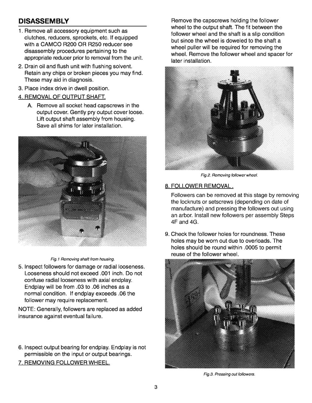
5 10. REMOVING SHAFT FROM OUTPUT ASSEMBLY. To remove the output shaft from the cover it will be necessary to use an arbor press and push from the back side of the shaft using caution not to damage the parts. C. Tap on the end of the input shaft to drive the opposite cartridge from the housing. Then drive the shaft in the opposite direction for removal of other cartridges. NOTE: Keep shims with their respective cartridges you will be asked to reinstall or replace with the same shim thickness during assembly. D. Remove the input shaft/cam assembly through the large cartridge hole (does not apply to 662RA see Step E). E. The 662RA requires removal of the cam locknuts while still in the housing and pressing the shaft through the hole previously occupied by the input cartridge and removed in Step C. This will automatically remove the bearing cone from one end of the input shaft. The use of an arbor press is recommended but this procedure can be accomplished by driving the shaft through with a soft faced hammer. Fig. 4 Pressing out shaft. 11. REMOVAL OF BEARINGS. A. Use a wheel puller to remove the cone portion of bearing from the shaft. B. Removal of the upper bearing cup from the output cover will require light tapping on the backside of the cup with a round aluminum bar and a hammer working around the perimeter as you tap to prevent binding. Continue this procedure until the cup is free of the cover. C. Removal of the lower output bearing cup from the output cover requires prying from the backside or drilling and tapping of jack screw holes or the use of a pulley puller. 12. INPUT SHAFT REMOVAL. NOTE: The output shaft must be removed prior to input shaft removal A. Rotate the input shaft and inspect all parts for damage. Endplay in the output shaft is not permissaable. B. Remove all input bearing cartridge capscrews. Fig. 5 Removing input shaft. F. Remove cam through the output opening. 13. REMOVAL OF CAM FROM OUTPUT SHAFT (400RA, 401RA AND 512RA) A. Use a wheel puller to remove the bearing cones from the input shaft. B. Using a spanner wrench remove the cam locknuts. C. Remove the spacers from the shaft. D. Use an arbor press to remove cam from shaft, using caution not to damage parts. 4


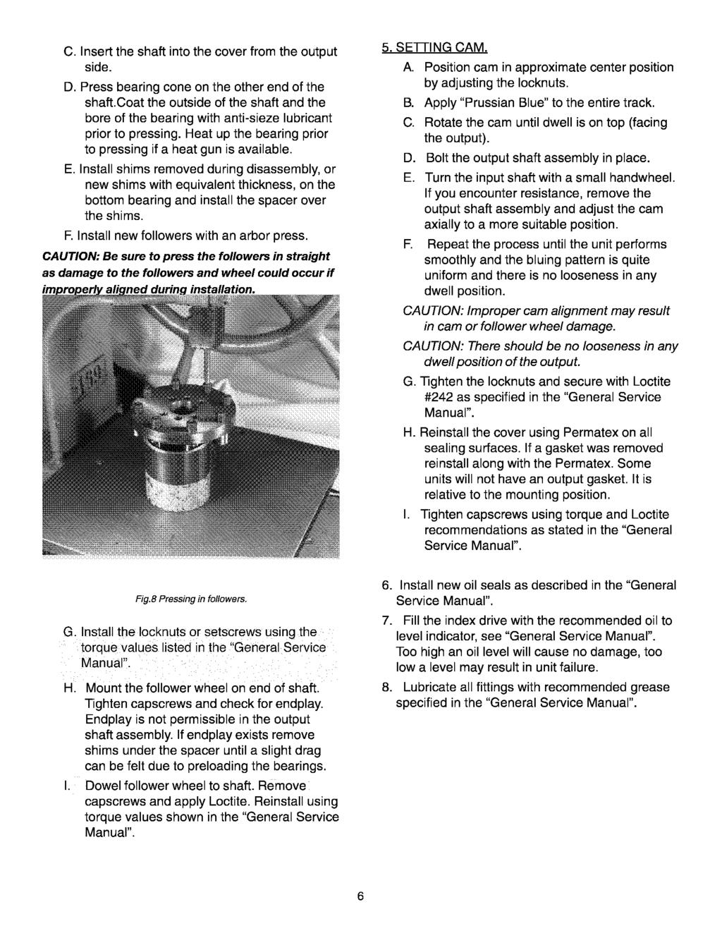
6 Fig. 6. Pressing out camshaft. 14. Remove the input bearing cups from the cartridges with a pulley puller, by prying or by drilling and tapping for jack screws. Fig. 7. Assembled camshaft. ASSEMBLY PRIOR TO REASSEMBLY. Clean and deburr all parts before reassembling. Follow tightening torque and Loctite recommendations as outlined in the General Service Manual. 1. Use an arbor to press the bearing cups into the cartridges. Coat the outside of the cup and the bore of the cartridge with an anti-seize lubricant prior to pressing. Fill cavity of cartridge with bearing grease recommended in the General Service Manual. 2. ASSEMBLING INPUT SHAFT. A. Use an arbor to press the cam into shaft. Be sure key is installed into shaft first. Apply anti-sieze lubricant to shaft and bore prior to pressing. B. Install spacers on both sides of the cam as removed in disassembly Step 13C. C. Use a spanner wrench to install the cam locknuts. Adjust nut to center cam on shaft. D. Use arbor to press bearing cones onto shaft. Coat shaft and bearing bore with antisieze lubricant prior to pressing. The bore of the bearing should be heated prior to pressing if a heat gun is available. 3. INSTALLING INPUT SHAFT INTO HOUSING. (On the 662RA the prior assembly steps were done inside the housing). A. Slip the input/cam shaft assembly through the large cartridge opening. B. Install the input cartridges. Be sure to install the same exact shims or equivalent height as was removed in disassembly Step 12C. C. Tighten cartridge mounting screws. D. If endplay exists remove an equal amount of shims from each side until there is a small amount of drag from the bearings. In rare instances it may be necessary to remachine the cartridges if all shims have been removed and endplay still exists. H. Loosen input cartridge screws and rotate the cartridge top to the most rearward position attainable within the slots provided in the cartridge. 4. ASSEMBLY OF OUTPUT SHAFT. A. Press bearing cups into cover. Coat the outside of the cup and the bore in the cover with an anti-sieze lubricant prior to pressing. B. Press bearing cone on the output end of the shaft. Coat the outside of the shaft and the bore of the bearing with anti-sieze lubricant prior to pressing. Heat up the bearing prior to pressing if a heat gun is available. 5
7
8
9
10
11
12
13
14
15 PARTS LIST FOR 512RA INDEX DRIVE (STANDARD CONFIGURATION CONT.) C OUTPUT RISINGLE EXTENDEDR (REQUIRED ON 90 AND... SOME 120 DEGREE MOTION UNITS) A SIGHT PLUG 3/8-18 N.P.T. *FS A GREASINGLE EXTENDED FITTING #B-1610 *FS A S.H.C.S. 5/16-18 X 2 *FS D BEARING CONE CLASS D BEARING CUP CLASS 2 32*... 86D BEARING CUP CLASS 2 33*... 86D BEARING CONE CLASS D OIL SINGLE EXTENDEDAL C/R B GASKET COVER CC *FS A SPACER, OUTPUT-CC A SHIM,.002 THK A SHIM,.003 THK A SHCS 3/8-16 X 3/ C MTG PLATE ALT R L MTG PLATE, SSV-7300C REDUCER L MOUNT PLATE 7300 CONE REDUCER 14
16
17 PARTS LIST FOR 662RA INDEX DRIVE (STANDARD CONFIGURATION CONT.) ITEM NO. PART NUMBER DESCRIPTION D OIL SINGLE EXTENDEDAL C/R C GASKET COVER CCM *FS B SPACER OUTP CCM 37*... 08A SHIM.002 THK 37*... 08A SHIM.003 THK 37*... 08A SHIM.005 THK 37*... 08A SHIM.010 THK A SHCS 3/8-24 X C MOUNTING PLATE 7300 REDUCER C MOUNTING PLATE 7350 REDUCER... *... Indicates parts supplied with Spare Parts Kit # 662RA SPK 16
18 Industrial Motion Control, LLC 1444 S. Wolf Road, Wheeling, IL Phone: Fax: The Driving Force in Automation Michigan Office 550 Forest Avenue, Unit # 14 Plymouth, Ml USA ph: fax: UK Office 432 Perth Avenue Slough Trading Estate Slough, Berkshire SL1 TS United Kingdom ph: +44 (0) fax: +44 (0) Belgium Office 33 Parc Industriel B-1440 Braine-le-Château Belgium ph: +32 (0) fax: +32 (0) Industrial Motion Control, LLC 2004 All rights reserved This publication is for information purposes only and should not be considered a binding Printed in U.S.A. description of the product except if confirmed in writing by Industrial Motion Control, LLC. SKU 0069 / Revision 3/1/04
SERVICE MANUAL RDM SERIES INDEX DRIVES MODELS 601RDM, 902RDM, 1100RDM 1305RDM, 1800RDM
 SERVICE MANUAL RDM SERIES INDEX DRIVES MODELS 601RDM, 902RDM, 1100RDM 1305RDM, 1800RDM WARNING This is a controlled document. It is your responsibility to deliver this information to the end user of the
SERVICE MANUAL TORQ-GARD OVERLOAD CLUTCH
 SERVICE MANUAL TORQ-GARD OVERLOAD CLUTCH The Driving Force in Automation WARNING This is a controlled document. It is your responsibility to deliver this information to the end user of the CAMCO/FERGUSON
DRIVE AXLE Nissan 240SX DESCRIPTION & OPERATION AXLE RATIO & IDENTIFICATION AXLE SHAFT & BEARING R & I DRIVE SHAFT R & I
 DRIVE AXLE 1990 Nissan 240SX 1990 DRIVE AXLES Rear Axle - R200 240SX, 300ZX DESCRIPTION & OPERATION The axle assembly is a hypoid type gear with integral carrier housing. The pinion bearing preload adjustment
Service Manual. #19 Gearmatic Winch
 Allis Chalmers Service Manual #19 Gearmatic Winch Service Manual THIS IS A MANUAL PRODUCED BY JENSALES INC. WITHOUT THE AUTHORIZATION OF ALLIS CHALMERS OR IT S SUCCESSORS. ALLIS CHALMERS AND IT S SUCCESSORS
Maintenance Instructions
 General Note These instructions contain information common to more than one model of Bevel Gear Drive. To simplify reading, similar models have been grouped as follows: GROUP 1 Models 11, 0, 1,, (illustrated),,
DRIVE AXLE - INTEGRAL HOUSING
 DRIVE AXLE - INTEGRAL HOUSING 1993 Toyota Celica 1993 DRIVE AXLES Toyota Differentials & Axle Shafts - Integral Housing Toyota; Celica All-Trac DESCRIPTION Drive axle assembly is a hypoid type with integral
KC Transmission Overhaul
 KC Transmissions Overhaul Instructions Form No. F-1031 Section 4310 Issue Date Rev. Date 02/08/96 12/30/15 Table of Contents Disassembling.............................. 1 Driven Shaft.................................
Amarillo PUMP DRIVES (250 HP THROUGH 350 HP) INSTRUCTIONS FOR REPAIRING MODELS 250, 300, and 350
 INSTRUCTIONS FOR REPAIRING MODELS 250, 300, and 350") Amarillo PUMP DRIVES (250 HP THROUGH 350 HP) INSTRUCTIONS FOR REPAIRING MODELS 250, 300, and 350 Amarillo Right Angle Pump Drives, if properly installed and maintained, should provide years of service
Amarillo PUMP DRIVES (250 HP THROUGH 350 HP) INSTRUCTIONS FOR REPAIRING MODELS 250, 300, and 350 Amarillo Right Angle Pump Drives, if properly installed and maintained, should provide years of service
REMOVAL & INSTALLATION
 REMOVAL & INSTALLATION AXLE SHAFTS & BEARINGS Removal CAUTION: Failure to turn off air suspension power before raising vehicle may result in unexpected inflation or deflation of air springs. DO NOT reconnect
INSTRUCTION AND MAINTENANCE MANUAL: FKL-25, 50, 75, 150, 250 and 400 Style Pump
 FKL Series Pump INSTRUCTION AND MAINTENANCE MANUAL: FKL-5, 50, 75, 150, 50 and 400 Style Pump SANITARY POSITIVE DISPLACEMENT PUMP Fristam Pumps Description This manual contains installation, operation
DIFFERENTIALS & AXLE SHAFTS
 DIFFERENTIALS & AXLE SHAFTS 2001 Chevrolet Camaro 2000-01 DRIVE AXLES General Motors Differentials & Axle Shafts Chevrolet; Camaro Pontiac; Firebird DESCRIPTION & OPERATION Drive axle is a semi-floating,
Falk Speed Reducers Right Angle/Vertical Drives Disassembly & Assembly
 Falk Speed Reducers Right Angle/Vertical Drives Disassembly & Assembly Type AFX Sizes 27 thru 88 (Page 1 of 10) HOW TO USE THIS MANUAL This manual provides detailed instructions on disassembly and assembly
3.2 DRIVE TORQUE HUB. Roll, Leak and Brake Testing SECTION 3 - CHASSIS & TURNTABLE. 3-2 JLG Lift
 3.2 DRIVE TORQUE HUB Roll, Leak and Brake Testing 10 LUG PATTERN Torque-Hub units should always be roll and leak tested before disassembly and after assembly to make sure that the unit's gears, bearings
TECHNICAL SERVICE MANUAL
 Electronic copies of the most current TSM issue can be found on the Viking Pump website at www.vikingcom TECHNICAL SERVICE MANUAL abrasive liquid pumps SERIES 4625 SIZES f - fh SECTION TSM 410.1 PAGE 1
PRODUCT OBSOLETED 4Q16
 Electronic copies of the most current TSM issue can be found on the Viking Pump website at www.vikingcom TECHNICAL SERVICE MANUAL abrasive liquid pumps SERIES 4625 SIZES f - fh SECTION TSM 410.1 PAGE 1
Installation Vertical Pump: Installation 'CM' and 'CDM' Style: Operation:
 Installation Vertical Pump: Gusher vertical end suction pumps with integral shaft is easily installed and put into service. With the one piece shaft design there is no couplings to align, no shims or no
Parts List Single Reduction Models, Cast Iron Units
 Parts List Single Reduction Models, Cast Iron Units 60 51 51 10 24 11 11 9 24 12 19 17 27 31 8 23 7 14 20 28 26 5 1 2 6 44 60 50 23 7 6 30 27 30 4 3 30 13 29 14 22 18 27 43 48 50 8 15 16 12 25 9 51 51
PROPELLER SHAFT & DIFFERENTIAL CARRIER SECTIONPD CONTENTS IDX. PROPELLER SHAFT...3 Preparation...3 C200. REAR FINAL DRIVE...40 Preparation...
 PROPELLER SHAFT & DIFFERENTIAL CARRIER SECTIONPD GI MA EM LC EC CONTENTS FE PROPELLER SHAFT...3 Preparation...3 SPECIAL SERVICE TOOLS...3 Noise, Vibration and Harshness (NVH) Troubleshooting...4 NVH TROUBLESHOOTING
PRODUCT OBSOLETED 1Q16
 TECHNICAL SERVICE MANUAL INDUSTRIAL ROTARY LOBE PUMP HIGH PRESSURE MODELS RL0167, 40167, 0257, 40257 SECTION PAGE ISSUE TSM270.2 1 B CONTENTS Introduction 1 Safety Information 1 Exploded Parts View 2 Torque
Input Cage Leak Repair
 Revised 10-12 Input Cage Leak Repair Technical Bulletin Meritor Forward Tandem Drive Axles RP 140 and 160 Series (With a Pump) MD and RD 140 and 160 Series (Without a Pump) Revised 1 Technical 10-12 Bulletin
TC20 Chain Driven Power Take-Off Overhaul Instructions
 TC20 Chain Driven Power Take-Off Overhaul Instructions Table of Contents Section Page Introduction 4 Ordering Repair Parts 4 General Information 5 Special Tools 6 Disassembly See Page 2 Reassembly See
Binks MODELS & AGITATOR DRIVE UNITS
 Binks MODELS 31-393 & 31-394 AGITATOR DRIVE UNITS for Agitator Equipped Drum MODEL 31-393 Includes the following items: 1, 2, and 3. 1 MODEL 31-394 shown. 17 4 3 2 12 13 14 15 2 3 8 5 9 11 8 10 6 7 17
REMOVAL & INSTALLATION
 REMOVAL & INSTALLATION CAUTION: This application is an interference engine. Do not rotate camshaft or crankshaft when timing belt is removed, or engine damage may occur. TIMING BELT Removal 1. Raise and
ProLine. 44 Mower. for 120 Traction Unit. Model No & Up. Operator s Manual
 FORM NO. 9 ProLine Mower for 0 Traction Unit Model No. 05 99000 & Up Operator s Manual IMPORTANT: Read this manual carefully. It contains information about your safety and the safety of others. Also become
REMOVAL & INSTALLATION
 REMOVAL & INSTALLATION TIMING BELT Removal 1. Disconnect negative battery cable. Raise and support vehicle. Remove lower engine cover. On Celica and Camry, remove right front wheel. On all models, lower
REMOVAL & INSTALLATION
 Page 1 of 11 REMOVAL & INSTALLATION TIMING BELT Tips Click a link to view tip Tech1 Question: Timing problems P0340 Tech1 Question: 2.2 TIMING PROBLEMS - RESOLVED Removal Tips Click a link to view tip
Disassembly Instructions hp. Dynafile II Models: 40352, 40353
 Disassembly Instructions - 0.4 hp. Dynafile II Models: 40352, 40353 Important: Use these instructions along with the tool parts page or manual. Notice: Shut off the air supply and depress throttle lever
DeZURIK " BAW AWWA BUTTERFLY VALVES WITH EPOXY-RETAINED SEAT
 DeZURIK 20 144" BAW AWWA BUTTERFLY VALVES WITH EPOXY-RETAINED SEAT Instruction D10373 April 2017 Instructions These instructions provide information about the 20 (250 F2 model only) and the 24-144 BAW
1984 Dodge W250 PICKUP
 1984 Dodge W250 PICKUP Submodel: Engine Type: V8 Liters: 5.2 Fuel Delivery: CARB Fuel: GAS Dana 44 MODELS THROUGH 1984 2. Raise and safely support the vehicle, then remove the wheel hub and bearings as
DRIVE AXLES. Differentials & Axle Shafts - Corvette
 DESCRIPTION & OPERATION 1998-99 DRIVE AXLES Differentials & Axle Shafts - Corvette A Getrag 625 model differential is used on both the automatic and manual transmissions. Differential carrier and case
TECHNICAL BULLETIN. TP Issued Servicing Rockwell s TB Series Trailer Axles with Unitized Hub Assemblies
 TECHNICAL BULLETIN TP-96175 Issued 12-96 Servicing Rockwell s TB Series Trailer Axles with Unitized Hub Assemblies TB Series Trailer Axles Introduction Rockwell s TB series trailer axle features a permanently
PROPELLER SHAFT & DIFFERENTIAL CARRIER SECTIONPD CONTENTS
 PROPELLER SHAFT & DIFFERENTIAL CARRIER SECTIONPD CONTENTS PREPARATION...2 PROPELLER SHAFT...5 On-Vehicle Service...6 Removal and Installation...7 Inspection...7 Disassembly...7 Assembly...8 ON-VEHICLE
SERVICE MANUAL L130B / L4130 Series Logstacker Drive Axle With Bolt-On Stub End Retainer
 SERVICE MANUAL L130B / L4130 Series Logstacker Drive Axle With Bolt-On Stub End Retainer Page 1 Allied Form #80-930 Rev 07/2009 SERVICE MANUAL LOG STACKER DA202 DRIVE AXLE TABLE OF CONTENTS PROCEDURE FOR
This file is available for free download at
 This file is available for free download at http://www.iluvmyrx7.com This file is fully text-searchable select Edit and Find and type in what you re looking for. This file is intended more for online viewing
GROUNDSMASTER. 52 Recycler. for 120 Traction Unit. Model No & UP. Operator s Manual
 FORM NO. 8-980 Rev A GROUNDSMASTER 5 Recycler for 0 Traction Unit Model No. 077 79000 & UP Operator s Manual IMPORTANT: Read this manual carefully. It contains information about your safety and the safety
Torque-Hub Planetary Final Drive S12A1 & 2 Series Service Manual
 Torque-Hub Planetary Final Drive S12A1 & 2 Series Service Manual Rev 8/30/13 1 While every precaution has been taken in the preparation of this document, Fairfield Manufacturing Co. Inc. assumes no liability
INSTRUCTION MANUAL AND PARTS LIST FOR SERIES 8L-630J AND 630M WARNING
 INSTRUCTION MANUAL AND PARTS LIST FOR SERIES 8L-630J AND 630M WARNING READ CA-l AND TIDS INSTRUCTION MANUAL PRIOR TO INSTALLATION, OPERATION OR MAINTENANCE WARNING This Instruction Manual and General Instructions
Model QED-D, QED-A, QED-L
 This supplement is for Field Service use only, as complete dis-assembly and re-assembly of the QED reducer by the customer is NOT recommended. This supplement only extends to single reduction QED units.
This file is available for free download at
 This file is available for free download at http://www.iluvmyrx7.com This file is fully text-searchable select Edit and Find and type in what you re looking for. This file is intended more for online viewing
1992 Toyota Cressida
 Monday, May 16, 2016 5:32:47 PM Page 13 2005 Mitchell Repair Information Company, LLC. Fig. 7: Exploded View Of Typical Cylinder Head & Components Fig. 8: Cylinder Head Bolt Removal Sequence Monday, May
Installation & Maintenance Manual SPRING ENGAGED FRICTION CLUTCHES THROUGH SHAFT MOUNT - BALL BEARING PILOT REGULAR DUTY
 Installation & Maintenance Manual SPRING ENGAGED FRICTION CLUTCHES THROUGH SHAFT MOUNT - BALL BEARING PILOT REGULAR DUTY Catalog Products: E3A2R-STH E4A2R-STH E5A2R-STH E6A2G-STH And non-catalog variations
OVERLOAD CLUTCHES FOR INDEX DRIVES
 The Driving Force in Automation OVERLOAD CLUTCHES FOR INDEX DRIVES WARNING WARNING This is a controlled document. It is your responsibility to deliver this information to the end user of the CAMCO indexer.
Disassembly Instructions hp. Mini-Dynafile II
 Disassembly Instructions - 0.4 hp. Mini-Dynafile II Important: Use these instructions along with the tool parts page or manual. Notice: Shut off the air supply and depress throttle lever to deplete the
ENG-14, Balance Shaft Oil Seal Replacement
 ENG-14, Balance Shaft Oil Seal Replacement Introduction The following procedure will provide instructions for replacing the balance shaft seals on a 944. It will also provide instructions for resealing
Installation, Operating and Maintenance Instructions. Rotating Machine Screw Actuators. With Parts List Publication Part No.
 Installation, Operating and Maintenance Instructions With Parts List Publication Part No. SK-2389-R1 Rotating Machine Screw Actuators 1/4 Through 1-Ton Capacity Caution This manual contains important information
CONTENTS. VIKING PUMP, INC. A Unit of IDEX Corporation Cedar Falls, IA USA SECTION TSM 710.1
 TECHNICAL SERVICE MANUAL industrial heavy duty motor speed pumps SERIES 4076 AND 4176 SIZES hle, ate and ale SECTION TSM 710.1 PAGE 1 of 8 ISSUE B CONTENTS Introduction....................... 1 Safety
AT Clutch Major Service Sizes 25, 55, 115
 P-1404 819-0324 AT Clutch Major Service Sizes 25, 55, 115 Installation Instructions Contents Introduction............................ 2 Warranty....................... back cover Failure to follow these
Front Hub and Disc (4WD Model)
") 4C 8 DRIVE SHAFT SYSTEM Disassembled View Front Hub and Disc (4WD Model) 411RW001 Legend (1) Bolt (2) Cap (3) Snap Ring and Shim (4) Hub Flange (5) Lock Washer and Lock Screw (6) Hub Nut (7) Outer Bearing
4C 8 DRIVE SHAFT SYSTEM Disassembled View Front Hub and Disc (4WD Model) 411RW001 Legend (1) Bolt (2) Cap (3) Snap Ring and Shim (4) Hub Flange (5) Lock Washer and Lock Screw (6) Hub Nut (7) Outer Bearing
Service Manual. MF2135 Industrial
 Massey Harris Massey Ferguson Service Manual MF2135 Industrial Service Manual THIS IS A MANUAL PRODUCED BY JENSALES INC. WITHOUT THE AUTHORIZATION OF MASSEY HARRIS MASSEY FERGUSON OR IT S SUCCESSORS. MASSEY
Gear Products Inc N. 161st E. Ave. Tulsa, OK Phone (918) Fax (918)
 Fax (918)") SERVICE MANUAL Disassembly & Assembly Procedures Worm Gear Swing Drive 003 Series Gear Products Inc. 1111 N. 161st E. Ave. Tulsa, OK 74116 Phone (918) 234-3044 Fax (918) 234-3455 Worm Gear Swing Drive
SERVICE MANUAL Disassembly & Assembly Procedures Worm Gear Swing Drive 003 Series Gear Products Inc. 1111 N. 161st E. Ave. Tulsa, OK 74116 Phone (918) 234-3044 Fax (918) 234-3455 Worm Gear Swing Drive
INSTRUCTION AND MAINTENANCE MANUAL:
 1 INSTRUCTION AND MAINTENANCE MANUAL: FKL Positive Displacement Pu m p Mo d e l s 25, 50, 75, 150, 205, 250, 400, a n d 580 SANITARY POSITIVE DISPLACEMENT PUMP 2 Description This manual contains installation,
DRIVE AXLE Volvo 960 DESCRIPTION & OPERATION AXLE IDENTIFICATION DRIVE AXLES Volvo Differentials & Axle Shafts
 DRIVE AXLE 1994 Volvo 960 1994 DRIVE AXLES Volvo Differentials & Axle Shafts 960 DESCRIPTION & OPERATION All 960 station wagon models use type 1041 rear axle assembly. All 960 4-door models use type 1045
Input Adjusting Ring Leak Repair Procedure for Meritor MT-14X Series Forward Differential Carriers
 Revised 01-16 Technical Bulletin Input Adjusting Ring Leak Repair Procedure for Meritor MT-14X Series Forward Differential Carriers Revised 1 Technical 01- Bulletin 16 Hazard Alert Messages Read and observe
SERIES1 NOZZLE CYLINDER REPAIR PROCEDURES
 THE FOLLOWING REPAIR PROCEDURE ENCOMPASSES THESE PHD ML UNITS : - ML309435, ML310142, ML310153, ML310254, ML310295, ML310427, 1) Refer to individual ML exploded view for actual part numbers. 2) Not all
TRANSMISSION 6.7 GENERAL HOME. See Figure The transmission is a five-speed constantmesh type housed in an extension of the crankcase.
 TRANSMISSION 6.7 GENERAL See Figure 6-46. The transmission is a five-speed constantmesh type housed in an extension of the crankcase. b06x6x Neutral st Gear Mainshaft Mainshaft 4 5 4 5 Countershaft Out
Transmission Overhaul Procedures-Bench Service
 How to Install the Auxiliary Countershaft Assembly Special Instructions To make auxiliary section assembly easier, you can make an auxiliary section fixture out of a 2" x 12" piece of wood. 3' 1' 3" 4.56"
2 SUSPENSION SYSTEM JEEP WRANGLER TJ
 2 SUSPENSION SYSTEM 997-2006 JEEP WRANGLER TJ JSPEC320 www.jksmfg.com jks@sporttruckusainc.com 57-278-226 RV. 09225 GETTING STARTED Read all warnings, instructions, notes and cautions before you begin
SMALL BLOCK CHEVY STANDARD CAM INSTALLATION INSTRUCTIONS
 SMALL BLOCK CHEVY STANDARD CAM INSTALLATION INSTRUCTIONS P/N s 251000-0002 SBC Gear Drive 1/2 Cam Hub 251000-0003 SBC Gear Drive 5/8 Cam Hub ****DUE TO MANUFACTURING TOLERANCES OF THE CAM, CRANK AND GEAR
70 Series 8700 End Mount Three Phase Brake Instructions IP56 (NEMA 4) Housing
 Housing") Bulletin No. BK4773-3 (08/2016) 70 Series 8700 End Mount Three Phase Brake Instructions IP56 (NEMA 4) Housing Read carefully before attempting to assemble, install, operate or maintain the product described.
Bulletin No. BK4773-3 (08/2016) 70 Series 8700 End Mount Three Phase Brake Instructions IP56 (NEMA 4) Housing Read carefully before attempting to assemble, install, operate or maintain the product described.
M-4851-M8A SUPER 8.8 IRS MUSTANG AUTOMATIC PINION FLANGE KIT
 Please visit fordperformanceracingparts.com for the most current instruction information!!! PLEASE READ ALL OF THE FOLLOWING INSTRUCTIONS CAREFULLY PRIOR TO INSTALLATION. AT ANY TIME YOU DO NOT UNDERSTAND
This file is available for free download at
 This file is available for free download at http://www.iluvmyrx7.com This file is fully text-searchable select Edit and Find and type in what you re looking for. This file is intended more for online viewing
REPAIR INSTRUCTION - MP4120-SWS/MP4124-SWS
 Disassembly sequence REPAIR INSTRUCTION - MP4120-SWS/MP4124-SWS 1. With a 27mm wrench, remove the three discharge plugs (#48) and three inlet plugs (#42A) from the manifold (#43). 2. Inspect the plug o-rings
S&S. Cycle, Inc. Installation Instructions: Cam Support Plate for 2017-up M8 Models. Instruction
 Instruction 0-0 0-0- Version 0 by S&S Cycle, Inc. All rights reserved. Printed in the U.S.A. S&S Cycle, Inc. 0 Cty Hwy G Viola, Wisconsin Phone: 0-- Fax: 0-- Technical Service Phone: 0--TECH () Technical
CP-1, CP-2, CP-2L & CPD-2 Series Overhaul
 Replacement of Mechanical Seals for CM, CMU, CS and CSU Series Pumps Installation Instructions Form No. F-1031 Section 5013 Issue Date 03/01/85 Rev. Date 02/08/11 CP-1, CP-2, CP-2L & CPD-2 Series Overhaul
Procedure to Install the New Autogap components in ER-1225 and ER825 Brake with inverted Armature Hub
 Procedure to Install the New Autogap components in ER-15 and ER85 Brake with inverted P-30-1 819-0376 Installation & Operating Instructions Contents Introduction........................... Kit Parts List..........................
Rineer 15 Series Hydraulic Motor Service Manual
 Section 4-2 Rineer 15 Series Hydraulic Motor Service Manual Removal of 15 Series Shaft Seal Step 1 Remove snap ring. See Figure 1. WARNING: Use caution when removing snap ring. If released accidentally,
REPAIR PROCEDURES MANUAL
 REPAIR PROCEDURES MANUAL PVX Series Vane Pumps A Design Series Step-by-Step Guide to Troubleshooting and Repairing PVX Series Vane Pumps Introduction Thank you for choosing Continental Hydraulics PVX Vane
Differential Bearings
 SECTION 205-02B: Rear Drive Axle/Differential Ford 8.8-Inch Ring Gear 2009 Mustang Workshop Manual IN-VEHICLE REPAIR Procedure revision date: 01/06/2010 Differential Bearings Special Tool(s) 2 Jaw Puller
Maintenance. Daily. Shutdown Procedure. Periodically. During Freezing Temperatures
 Maintenance Daily Check the oil level and the condition of the oil. When the pump is operating, the oil in the pump housing gets warm and expands, filling into the oil reservoir. Depending on the type
Differential Bearings
 SECTION 205-02A: Rear Drive Axle/Differential Ford 7.5-Inch Ring Gear 2009 Mustang Workshop Manual IN-VEHICLE REPAIR Procedure revision date: 04/02/2009 Differential Bearings Special Tool(s) 2 Jaw Puller
SERVICE MANUAL TC 180 TRANSFER CASE SERVICE MANUAL
 TC 180 TRANSFER CASE SERVICE MANUAL Table of Contents MODEL TC-180, Transfer Case........1.0 Introduction.......1.1 Assembly Views.......... 1.2 LUBRICATION...... 2.0 Recommended Lubricants....2.1 Inspection.........
70 Series 8700 Coupler 2-pc Hub & Shaft Three Phase Brake Instructions IP43 & IP56 (NEMA 2 & 4) Housing
 Housing") Bulletin No. BK4775-3 (08/2016) 70 Series 8700 Coupler 2-pc Hub & Shaft Three Phase Brake Instructions IP43 & IP56 (NEMA 2 & 4) Housing Read carefully before attempting to assemble, install, operate or
Bulletin No. BK4775-3 (08/2016) 70 Series 8700 Coupler 2-pc Hub & Shaft Three Phase Brake Instructions IP43 & IP56 (NEMA 2 & 4) Housing Read carefully before attempting to assemble, install, operate or
1. Remove the parking brake assembly. 2. Remove the 4 bolts holding the yoke flange and drum. Remove the yoke flange and drive.
 Disassembly NOTE: To replace the brake assembly, brake shoe and lining assemblies, or other operational components the complete parking brake assembly must be removed from the vehicle. 1. Remove the parking
Auto mo tive Cor po ra tion TC 237 TRANSFER CASE SERVICE MAN UAL. Fabco Automotive Corporation Livermore, CA
 Auto mo tive Cor po ra tion TC 237 TRANSFER CASE SERVICE MAN UAL Fabco Automotive Corporation Livermore, CA TABLE OF CONTENTS Introduction and Specifications 3 Front View 4 Rear View 5 Lubrication Types
STEERING SYSTEM 6 A POWER STEERING
 STEERING SYSTEM 6 A 22147 POWER STEERING Table of Contents Page Specifications............................ 6A-1 Torque Specification................... 6A-1 Special Tools............................ 6A-1
IMPORTANT WARRANTY & INSTALLATION INSTRUCTIONS ATTACHED
 IMPORTANT WARRANTY & INSTALLATION INSTRUCTIONS ATTACHED Please Forward All Attached Information to Consumer Warranty Not Valid Unless Returned to CORSA Performance We ask that you take a few moments to
REPAIR MANUAL URW SERIES. URW-6, 8, 9, 10 & 12 Series Repair Manual
 REPAIR MANUAL URW SERIES URW-6, 8, 9, 10 & 12 Series Repair Manual Contents Page 1. Tools Needed for Repair 1 2. Disassembly and Reassembly of the Cam Casing 2-4 3. Disassembly and Reassembly of the Gear
TRANSMISSION 6.7 GENERAL HOME. See Figure The transmission is a five-speed constantmesh type housed in an extension of the crankcase.
 TRANSMISSION 6.7 GENERAL See Figure 6-45. The transmission is a five-speed constantmesh type housed in an extension of the crankcase. Mainshaft Neutral Mainshaft st Gear b06x6x Countershaft 4 Out 5 Countershaft
SERVICE BULLETIN THIS BULLETIN IS FAA APPROVED FOR ENGINEERING DESIGN
 MOONEY AIRPLANE COMPANY, INC. SERVICE BULLETIN Louis Schreiner Field Kerrville, Texas 78028 DATE: October 30, 2003 THIS BULLETIN IS FAA APPROVED FOR ENGINEERING DESIGN SERVICE BULLETIN M20-282 DATE: October
Installation. Installation Instructions Monotube Cartridge Fork Kit 97-Later* Harley Davidson FLH/FLT
 Installation Instructions Monotube Cartridge Fork Kit 97-Later* Harley Davidson FLH/FLT ATTENTION Statements in these instructions that are preceded by the following words are of special significance:
Differential Ring And Pinion
 SECTION 205-02B: Rear Drive Axle/Differential Ford 8.8-Inch Ring Gear 2009 Mustang Workshop Manual IN-VEHICLE REPAIR Procedure revision date: 01/06/2010 Differential Ring And Pinion Special Tool(s) 2 Jaw
Service Parts Instructions
 Issued 07-00 Service Parts Instructions RPL Series Permalube TM Generation II Driveline Removal and Installation WARNING To prevent serious eye injury, always wear safe eye protection when you perform
70 Series 8700 End Mount Three Phase Brake Instructions IP43 (NEMA 2) Housing
 Housing") Bulletin No. BK4772S-3 (6/2017) 70 Series 8700 End Mount Three Phase Brake Instructions IP43 (NEMA 2) Housing Read carefully before attempting to assemble, install, operate or maintain the product described.
Bulletin No. BK4772S-3 (6/2017) 70 Series 8700 End Mount Three Phase Brake Instructions IP43 (NEMA 2) Housing Read carefully before attempting to assemble, install, operate or maintain the product described.
EP-2 Si Three-Piston Pump
 EP- Si Three-Piston Pump Customer Product Manual Issued 0/ For parts and technical support, call the Industrial Coating Systems Customer Support Center at (800) -99 or contact your local Nordson representative.
INSTRUCTION AND MAINTENANCE MANUAL:
 1 INSTRUCTION AND MAINTENANCE MANUAL: FKL Positive Displacement Pump Models (original design, pre-2011): 25, 50, 75, 150, 205, 250 Models (original design, pre-2015): 400 Models: 580, 600 SANITARY POSITIVE
Rex Mounted Roller Bearings
 2000, 0, 00, & 9000 Series WARNING: These instructions should be read entirely and followed carefully before attempting to install or remove Rex roller bearings. Failure to do so can result in improper
AMARILLO PUMP DRIVES MODEL 1 OOOA, 1200, 1500, 1800
 AMARILLO PUMP DRIVES MODEL 1 OOOA, 1200, 1500, 1800 INSTRUCTIONS FOR REPAIRING MARCH 1, 1993 AMARILLO GEAR COMPANY Post Office Box 1789, Amarillo, Texas 79105 806 / 622-1273 FAX 806 / 622-3258 INSTRUCTIONS
ASSEMBLY INSTRUCTIONS
 ASSEMBLY INSTRUCTIONS FOR DYNALITE PRO SERIES FRONT HUB KIT WITH.75 DIAMETER VENTED ROTOR 970-973 FORD MUSTANG (DRUM / DISC SPINDLE) PART NUMBER GROUP 0-905 WARNING INSTALLATION OF THIS KIT SHOULD ONLY
Owner smanual. Banks TorqueTube System Ford 5.4L F-150 (Late Body Style) with Installation Instructions
 with Installation Instructions") Owner smanual with Installation Instructions Banks TorqueTube System 2004-2008 Ford 5.4L F-150 (Late Body Style) THIS MANUAL IS FOR USE WITH SYSTEMS 48715 Gale Banks Engineering 546 Duggan Avenue Azusa,
Owner smanual with Installation Instructions Banks TorqueTube System 2004-2008 Ford 5.4L F-150 (Late Body Style) THIS MANUAL IS FOR USE WITH SYSTEMS 48715 Gale Banks Engineering 546 Duggan Avenue Azusa,
X-Trainer 43mm fork service manual. Beta USA, Inc This work should be performed by a trained motorcycle technician.
 X-Trainer 43mm fork service manual Beta USA, Inc. 2016 This work should be performed by a trained motorcycle technician. Table of contents Page Introduction/special tools... 2 Fork exploded view... 3 Legend.
MODELS 48 RA 48 BRA2 48 BRA4 48 BRAD 48 RAS 48 RAZ 48 RAD 48 RAC
 General Safety and Maintenance Manual Model Number 48BRA 48BRAZ 48BRAC 48BRAD Exhaust Direction Front or Side Throttle Type (L) Lever or (K) Safety Lever Speed 9000 to 11000 R.P.M. (11000 is Standard)
DelTech Controls L.L.C.
 DelTech Controls L.L.C. DelTorq Series 20 ACTUATORS TECHNICAL DATA SHEET T.D.S. NO. 20 105 / R1 ISSUE DATE : NOV 2004 INSTALLATION, OPERATION AND MAINTENANCE MANUAL Guarantee : ( Please read the entire
INSTALLATION INSTRUCTIONS
 INSTALLATION INSTRUCTIONS INSTALLATION INSTRUCTIONS FOR A136 REAR DRUM TO DISC BRAKE CONVERSION KIT for 1970-75 Jeep, CJ SERIES with Dana 44 flanged axle Thank you for choosing STAINLESS STEEL BRAKES CORPORATION
1989 Jeep Cherokee. STEERING COLUMN' '1989 STEERING Jeep Steering Columns STEERING COLUMN STEERING Jeep Steering Columns
 STEERING COLUMN 1989 STEERING Jeep Steering Columns DESCRIPTION All models use collapsible steering columns. All columns have integral ignition switch and locking device. Optional tilt wheel is available
DRIVE AXLE - 4WD MODELS WITH INTEGRAL HOUSING
 DRIVE AXLE - 4WD MODELS WITH INTEGRAL HOUSING 1988 Toyota Celica DRIVE AXLES Toyota Integral Housing Celica (Rear) DESCRIPTION housing. Drive axle assembly is hypoid type with integral carrier AXLE RATIO
Dethatcher Kit Greensmaster 3000 Series
 Form No. 338 944 Dethatcher Kit Greensmaster 3000 Series Model No. 04493 Serial No. 3000000 and Up Operator s Manual English (EN) Contents Page Specifications............................... General Specifications.....................
Ram Drives Disassembly & Assembly Instructions
 Ram Drives Disassembly & Assembly Instructions Types MDX & MDXT Sizes 300 thru 900 (Page 1 of 16) This manual provides detailed instructions on disassembly, assembly and parts replacement of Types MDX
INSTALLATION & SERVICE MANUAL FD & SENTRY SERIES DRIVES
 INSTALLATION & SERVICE MANUAL FD & SENTRY SERIES DRIVES WARNING This is a controlled document. It is your responsibility to deliver this information to the end user of the CAMCO or FERGUSON product. Failure
TECHNICAL SERVICE MANUAL
 Electronic copies of the most current TSM issue can be found on the Viking Pump website at www.vikingpump.com TECHNICAL SERVICE MANUAL industrial heavy duty motor speed pumps SERIES 4076 AND 4176 SIZES
STERNDRIVE UNIT 3 A DRIVE SHAFT HOUSING
 STERNDRIVE UNIT 3 A 23262 DRIVE SHAFT HOUSING Table of Contents Page Specifications............................ 3A-1 Torque Specifications.................. 3A-1 Upper Drive Shaft Bearing Preload.......