REPAIR MANUAL 5 HP - 18 ZF GETRIEBE GMBH SAARBRÜCKEN
|
|
|
- Neal McBride
- 6 years ago
- Views:
Transcription
1 REPAIR MANUAL 5 HP - 18 ZF GETRIEBE GMBH SAARBRÜCKEN
2 Impressum: Verantwortlich für den Inhalt Abteilung MKTD, ZF Getriebe GmbH, Saarbrücken Druck: HAGER PAPPRINT GmbH, St. Ingbert Gedruckt in der BRD Published by ZF Getriebe GmbH, Saarbrücken, Department-MKTD Printed in Germany by HAGER PAPPRINT GmbH, St. Ingbert.
3 CONTENTS Page Preliminary information 1 1. General remarks Drawing of transmission Power flow schematic Oil flow charts Adjustment work 5/ Release clearance at clutch F (snap ring) 5/ Release clearance at brake G (snap ring) 5/ Release clearance at brake D (snap ring) 5/ Clearance at output side (washer) 5/ Release clearance at clutch E (snap ring) 5/ Release clearance at clutch A (snap ring) 5/ Release clearance at brake C 1 (snap ring) 5/ Transmission axiale clearance (washer) 5/ Release clearance at brake C 2 (two washers) 5/ Tightening torques Troubleshooting (faults, causes and remedies) 7/1 1.7 Checking the transmission Special tools 9 2. Dismantling Dismantling according to assembly groups Output side Planetary gears, complete Planetary gear set III Clutch F Brake DG with 1st gear freewheel Input side Clutch E Clutch A Clutch B and 3rd gear freewheel Brake C Oil supply unit with brake C Housing with shift and parking pawl Assembling according to assembly groups Housing with shift and parking pawl Planetary gear set, complete Planetary gear set III Clutch F Brake DG with 1st gear freewheel Output side Planetary gear sets I and II Input side Clutch E Clutch A Clutch B and 3rd gear freewheel Brake C Oil supply unit with brake C Selector unit, oil sump and converter 75
4 PRELIMINARY INFORMATION This manual contains precise details of how to repair the complete transmission. Al dismantling and assembly work is described in the correct order. The photographs have been selected to cover various types of transmission and may therefore differ from the vehicle on which you are working. The component list precisely defines which version of the transmission you are working on, and this is also reflected in the parts list. If any major modifications have to be taken into account when repairs are carried out, you will be notified by Technical Bulletin. Depending on the nature of the fault, it may be possible to limit the repair to the actual components and areas of the transmission that have failed. In this connection, please note: - Always renew the pistons if there is a fault on clutch F or brake G. Never re-use seals, for example 0-rings and shaft sealing rings. - If the transmission has been run for a considerable distance ( > km), renew all lined and steel discs. - If clutch damage has occurred the converter, oil cooler lines and the oil cooler itself must be thoroughly flushed out with a suitable cleaning agent. The following conditions must be satisfied: - The necessary special tools must be available The complete set is listed in Section 1.8 of this manual. - A suitable transmission test rig should be available. Refer to the Technical Bulletins for the relevant test values. NOTE: In this manual the control unit is treated as a single element; it shoult always be exchanged as a complete unit and not dismantled except by suitably trained personnel possessing full knowledge of its design. Warning: The transmission should only be delivered with the oil content stated in the relevant component list (on microfiche). 1

5 1. General information 1.1 Drawing of transmission 2
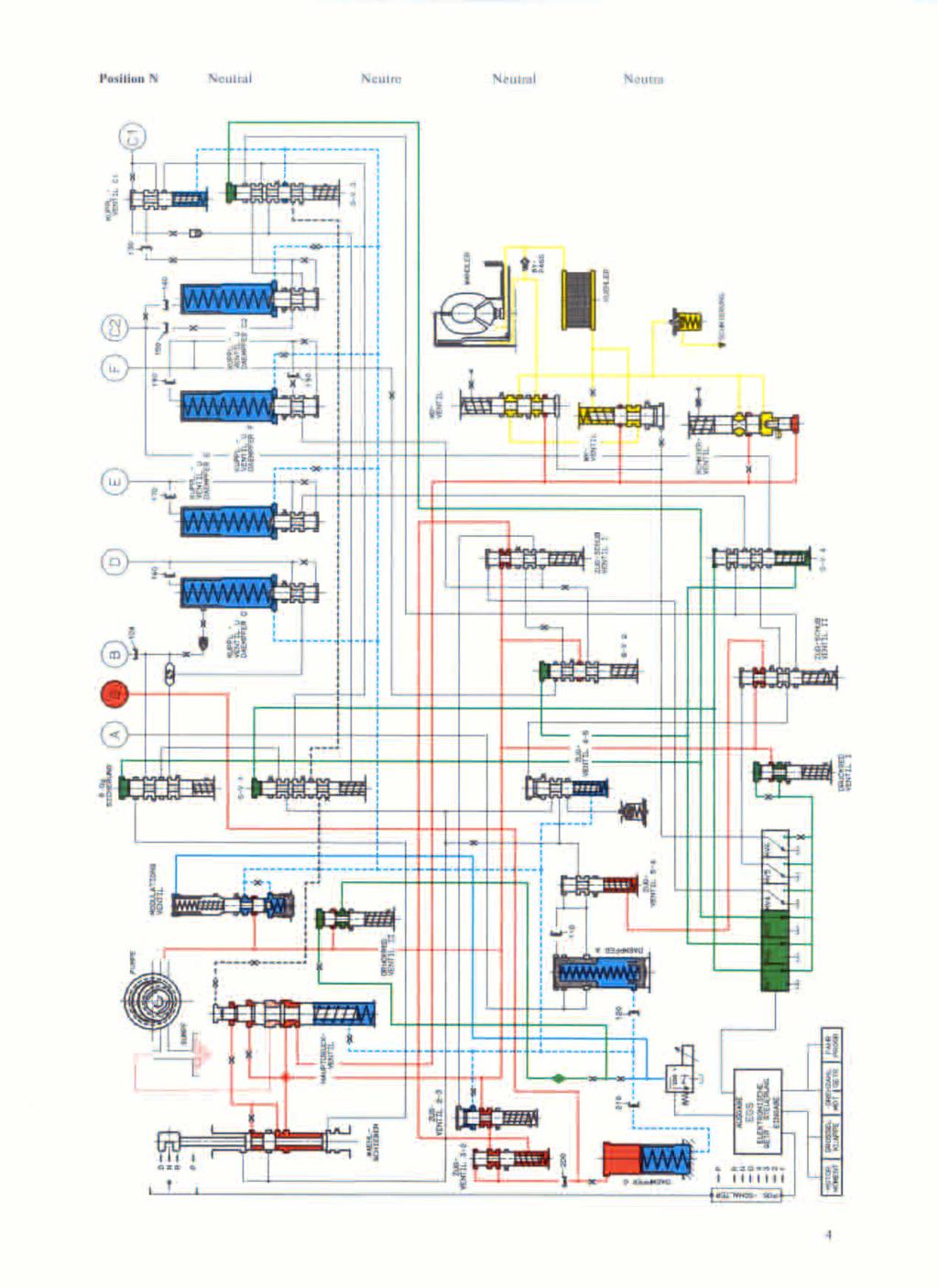
6 1.2 Power flow For a full description, refer to seperate documentation. 3
7
. Place dial gauge and bar in position.")


8 1.4 Adjustment work Release clearance at clutch F (snap ring) Insert snap ring /180. (Selected thickness = 1.9 mm). Place dial gauge and bar in position. Extend dial gauge pointer until it touches the end disc, and set dial gauge to O Raise the complete disc set and read off play at the dial gauge. It should be: with 4 lined discs = 1,30 to 1,60 mm with 5 lined discs = 1,65 to 1,95 mm If a different reading is obtained, select a thicker or thinner snap ring /1
 Place dial gauge with bar in position.")

9 1.4.2 Release clearance at brake G (snap ring) Insert complete disc set G. Starting with spring disc , insert steel discs and lined discs alternately. Place final disc in position and insert snap ring (Selected thickness = 2.1 mm.) Place dial gauge with bar in position. Extend the dial gauge pointer as far as the final disc and set the dial gauge to O. Raise the complete disc set and read off play at the dial gauge. It should be: with 3 pairs of discs = 0.95 to 1.25 mm with 4 pairs of discs = 1.30 to 1.60 mm If a different reading is obtained, select a thicker or thinner snap ring /2

 Place dial gauge with bar in position.")

10 1.4.3 Release clearance at brake D (snap ring) Insert complete set. Starting with spring disc /160, insert steel discs /170 and lined discs /180 alternately. Place final disc /190 in position and insert snap ring /200. (Selected thickness = 3.0 mm) Place dial gauge with bar in position. Extend the dial gauge pointer as far as the final disc and set the dial gauge to O Raise the complete disc set and read off play at the dial gauge. It should be: with 5 pairs of discs = 1.75 to 2.26 min with 6 pairs of discs = 2.09 to 2.74 mm If a different reading is obtained, select a thicker or thinner snap ring /3


11 1.4.4 Clearance at output side (washer) Support the dial gauge bar at approx. 140 mm intervals with approx. 20 mm thick gauge blocks. Set the dial gauge to O on a gauge plate. Place the output side on a suitable underlay or clamp into a vise. Warning! Do not place on the output flange. To avoid incorrect readings, move the output flange towards the output side so that play is eliminated Determine distance A: Measure between the machined face on the extension and the hub of the output flange Example: distance A = 2.50 mm 5/4


12 Determine distance B: Using a depth gauge, measure between machined faces on transmission housing and parking pawl gear. Example: distance B = 3.80 mm Determine washer thickness S by the following formula: S = distance B distance A play acc. to gauge clearance acc. parts list Play acc. to gauge = 0.15 to 0.35 mm introduction date: Example: S = 3.80 mm-2.50 mm-0.15 to 0.35 mm S = 0.95 mm to 1.15 mm /5


13 1.4.5 Release clearance at clutch E (snap ring) Insert snap ring (Selected thickness = 1.5 mm). Place dial gauge with bar in position. Extend the dial gauge pointer as far as the final disc and set the dial gauge to O Raise the complete disc set and read off play at the dial gauge. It should be: with 4 pairs of discs = to 2.11 mm with 5 pairs of discs = to 2.50 mm If a different reading is obtained, select a thicker or thinner snap ring /6
 Place dial gauge with bar in position.")


14 1.4.6 Release clearance at clutch A (snap ring) Insert snap ring /230. (Selected thickness = 1.4 mm.) Place dial gauge with bar in position. Extend the dial gauge pointer as far as the final disc and set the dial gauge to O Raise the complete disc set and read off play at the dial gauge. It should be: with 4 pairs of discs = 1.30 to 1.60 mm with 5 pairs of discs = 1.65 to 1.95 mm If a different reading is obtained, select a thicker or thinner snap ring /7
. Place dial gauge with bar in position.")


15 1.4.7 Release clearance at brake C 1 snap ring) Insert snap ring (Selected thickness = 1,5 mm). Place dial gauge with bar in position. Extend the dial gauge pointer as far as the final disc and set the dial gauge to O Raise the complete disc set and read off play at the dial gauge. It should be: with 3 pairs of discs = 0.95 to 1.25mm with 4 pairs of discs = 1.30 to 1.60mm If a different reading is obtained, select a thicker or thinner snap ring /8
 are attached to the intermediate plate with grease.")

 See also adjacent picture.")
16 1.4.8 Transmission axiale clearance (washer) Requirements: Angle disc , needle roller thrust bearing and shim washer (selected thickness = 2.0 mm) are attached to the intermediate plate with grease Clamp assembly fixture 5 X on to the stator shaft and align the rectangular-section rings on centering fixture 5 X Insert the oil supply unit, at the same, time turning in both directions until the diaphragm spring of brake C is touching the housing. (Test by applying pressure: spring contact should be felt.) See also adjacent picture. Warning! This is a difficult assembly operation and must be carried out with great care /9
.")

.")
17 Attach the oil supply unit with two machine screws on opposite sides. (Wrench size = TX-27). (Tightening torque = 10 Nm) Clamp the sleeve of measurin device 5 P by its 3 retaining bolts to the stator shaft, so that no play is present. Push measuring device 5 P over the input shaft splines and secure with the locking screw so that it can not tilt Pull the handle to determine end play (take the measurement more than once). Desired end play value = mm. If this value is not reached, insert a thicker or thinner washer , than check end play again. Unscrew and lift out the oil supply unit /10


18 1.4.9 Release clearance at brake C 2 (two washers) Requirements: 1.The fully assembled piston and washer and shim washer , must be installed. 2. Cover must be inserted and secured with snap ring Example: Shim washer = 3.25 mm thick; washer = 3.25 mm thick Since the release clearance must be determined under load, it is essential to use measuring device 5P Set the dial gauge to O in the off-load position Tension the measuring device by moving the eccentric lever round. The release clearance can then be determined and read off at the dial gauge. (Example: measure release clearance = 1.80 mm) Desired release clearance 1.35 to 1.70 mm /11

19 If the release clearance is too large, insert a thicker shim washer and a thinner washer If it is too small, the opposite procedure applies. Important: Select washers as shown in the adjacent table. Paired washers Shim washer Washer Pos Pos (mm) (mm) 1,50 5,00 1,75 4,75 2,00 4,50 2,25 4,25 2,50 4,00 2,75 3,75 3,00 3,50 3,25 3,25 3,50 3,00 3,75 2,75 4,00 2,50 4,25 2,25 Example: Install a 3,50 mm thick shim washer with a 3,00 mm thick washer /12
20 1.5 Tightening torques Item Wrench See Tightening size page torque Screw plug (transmission housing) 5 mm Allen screw 35/73 15 Nm Machine screw (detent spring) TORX-TX Nm Screw plug (pawl pin) 6 min Allen screw Nm Machine screw (guide plate) TORX-TX Nm Machine screw (complete planetary gear set) TORX-TX See directive Slotted nut (output side) Socket wrench Nm 5 X Machine screw (output side) 13 mm across Nm flats Csk. screw (intermediate plate, pump) TORX-TX Nm Machine screw (oil supply unit) TORX-TX 27 5/10 10 Nm and 71 Hex nut (wiring harness) 32 mm across Nm flatsf Machine screw (selector unit) TORX-TX Nm Machine screw (filter) TORX-TX Nm Screw plug (oil sump) 5 mm Nm M 10 x 1 Allen screw Screw plug (oil sump) 17 mm Nm M 30 x 1,5 Allen screws Collar nut (oil sump) 30 mm across 76 Pre-assembly: 20 Nm flats Final assembly: 100 Nm Hex bolt (oil sump) 10 mm across 77 6 Nm flats 6
21 Introduction Troubleshooting 5 HP 18 EH automatic transmission and electronic-hydraulic selector unit The troubleshooting table which follows is intended as an aid to diagnosing malfunctions in the ZF 5 HP 18 EH automatic transmission and taking the correct remdial action. The malfunctions have been stated in the same way as the customer would generally describe them. However, the same fault can often be described in different ways; the person accepting the customer's instructions should bear this in mind when deciding which fault may have occurred. If leaks are complained of, it is best to determine the precise leakage point before attempting any sealing work. This can be done with a suitable crack testing agent such as Met-L-Chek This product is available as a spray from trade outlets.after it has been applied and a short test run undertaken, the leakage point can be accurately located. Warning: For all troubleshooting work on the automatic transmission, it is assumed that both the mechanical and electrical peripherals (transmitted signals, cables and lines) are in good working order. In terms of the vehicle's control circuits, the automatic transmission is a passive element and will also carry out incorrect commands (information) from the periphery. It is wrong to assume that such commands represent faults in the automatic transmission. Notes on troubleshooting in peripheral equipment are included. 7/1
22 Troubleshooting 5 HP 18 EH automatic transmission Malfunction Possible cause Remedial action 1. Position P 1.1 Park position shift cable between selector lever adjust correctly does not engage and transmission is incorrectly reliably adjusted too much friction in parking renew parking interlock mechanism interlock components (connecting rod, pawl) 1.2 Park position does shift cable between selector lever adjust correctly not stay engaged and transmission is incorrectly (slips out) adjusted, 1.3 Engine cannot position switch incorrectly adjust correctly be started adjusted position switch defective renew position switch 1.4 Engine starts incorrect position switch fit correct although lever position switch is in park position selector lever not correctly adjusted adjust correctly position switch defective renew position switch 2. Position R 2.1 Reverse gear not shift cable between selector lever adjust correctly available and transmission is incorrectly adjusted clutch B damaged beyond repair fit an exchange transmission Brake D damaged fit an exchange beyond repair (in this case, no transmission braking effect in position 2, 1st gear) brake G damaged beyond repair fit an exchange transmission see troubleshooting on hydraulic selector unit, item Violent jerk when engine idle speed adjust to shifting from > 1500 min correct idle P R or N R speed see troubleshooting on hydraulic selector unit, item 1.2 7/2
23 Troubleshooting 5 HP 18 EH automatic transmission Malfunction Possible cause Remedial action 2.3 Reversing light position lever incorrectly adjusted adjust correctl does not come on position switch defective renew position (vehicle's electrics switch in working order) 3. Position N 3.1 Engine cannot be position lever incorrectly adjusted adjust correctly started position switch defective renew position switch 3.2 Vehicle moves clutch A defective (discs fused fit an exchange (creeps) forward together) transmission shift cable between selector lever adjust correctly and transmission is incorrectly adjusted 4. Position D 4.1 Engine stalls when converter lockup clutch engaged all see troubleshifting from N to D the time shooting on hydraulic selector unit, item No power clutch A damaged beyond repair fit an exchange transmitted transmission fault in shift cable between check setting selector lever and transmission and adjust if necessary defective lst gear freewheel fit an exchange transmission 4.3 Violent jerk when engine idle speed > 1500 min adjust to correct shifting from N D idle speed see troubleshooting on hydraulic selector unit, item 2.2 7/3
24 Troubleshooting 5 HP 18 EH automatic transmission Malfunction Possible cause Remedial action 4.4 No shift action see troubleshooting on hydraulic (whether warm selector unit, items or cold) Items No shift action brakes Cl and C2 defective fit an exchange from 1 2 transmission inadequate oil supply to brakes fit an exchange C1 and C2 transmission No shift action see troubleshooting on hydraulic from 2 1 selector unit, item No shift action clutch F defective fit an exchange from 2 3 transmission inadequate oil supply to fit an exchange clutch F transmission No shift action see troubleshooting on hydraulic from 3 2 selector unit, item No shift action clutch E defective fit an exchange from 3 4 transmission inadequate oil supply to clutch E fit an exchange transmission No shift action brake band C2 defective; in this fit an exchange No braking case 1 2 shift also not working transmission effect from correctly 4 3 inadequate oil supply to brake C2 - fit an exchange transmission no preload at brake band C2 adjust the (spring broken; in this cas 1 2 brake band shift also not working correctly) 7/4
25 Troubleshooting 5 HP 18 EH automatic transmission Malfunction Possible cause Remedial action No shift action see item from No shift action clutch A defective; in this case fit an exchange from 5 4 lst to 4th gears also out of action transmission 4.5 Vehicle moves see troubleshooting on away in 2nd gear hydraulic selector unit, item Vehicle moves see troubleshooting on hydraulic away in 3rd gear selector unit, item Vehicle moves see troubleshooting on hydraulic away 4th gear selector unit, item Shift transition see troubleshooting on hydraulic off-load too selector unit, item 2.8 violent 4.9 Shift transitions see troubleshooting on hydraulic at full load too selector unit, item 2.9 violent 4.10 Shift discs damaged fit an exchange transitions at transmission full load or see troubleshooting on kick-down take hydraulic selector unit, too long item /5
26 Troubleshooting 5 HP 18 EH automatic transmission Malfunction Possible cause Remedial action 4.11 No downshifts see notes on troubleshooting for when kick-down peripherals, item 1 is operated 4.12 Engine speed low friction at discs fit an exchange rises steeply transmission during 2 3/ see troubleshooting on hydraulic 3-2 shifts selector unit, item Engine speed low fiction at discs fit an exchange rises steeply transmission during 4 5/ see troubleshooting on hydraulic 5-4 shifts selector unit, item 2.12F 4.14 Engine speed low friction at discs fit an exchange rises steeply transmission during 2-1 1st gear freewheel not operating fit an exchange shifts correctly transmission 4.15 Engine speed low friction at discs fit an exchange rises steeply transmission during 4-3 3rd gear freewheel not operating fit an exchange shifts correctly transmission 5. Position See items No engine clutch A damaged fit an exchange braking effect, transmission no manual 5-4 see troubleshooting on hydraulic downshift possible selector unit, item and notes on troubleshooting for peripherals, item 2 7/6
27 Troubleshooting 5 HP 18 EH automatic transmission Malfunction Possible cause Remedial action 6. Position See items No engine braking see troubleshooting on hydraulic effect, no manual selector unit, item and notes 4 3 downshift on troubleshooting for peripherals, possible item 2 7. Position See items No engine see troubleshooting on hydraulic braking effect, selector unit, item and notes no manual 3-2 on troubleshooting for downshift possible peripherals, item No 1st gear, brake D defective no braking effect see troubleshooting on hydraulic selector unit, item Converter lockup clutch (WK) 8.1 Shifts too violent converter defective fit an exchange converter see troubleshooting on hydraulic selector unit, item 3.1 7/7
28 Troubleshooting 5 HP 18 EH automatic transmission Malfunction Possible cause Remedial action 8.2 Converter does converter defective fit an exchange not lock up converter see troubleshooting on hydraulic selector unit, items 3.2 and Engine stalls when converter defective fit an exchange vehicle is halted converter with a gear selected see troubleshooting on hydraulic (converter lock-up selector unit, item 3.3 clutch does not open) 9. General 9.1 No drive either pump impeller driver forced off fit an exchange forward or in converter reverse, loud noises 9.2 Generally poor see troubleshooting on hydraulic shift quality selector unit, item Noise 10.1 Noise in all oil level too low add oil to positions (suction correct level noise) selector unit leaking fit an exchange selector unit oil filter blocked fit an exchang oil filter missing or damaged O-ring seals at renew O-ring oil filter seals 11. Leaks leaking usit rings renew usit rings 11.1 Oil dripping from leaking shaft sealing ring renew shaft converter bell sealing ring housing leakig O-ring renew O-ring 7/8
29 Troubleshooting 5 HP 18 EH automatic transmission Malfunction Possible cause Remedial action 11.2 Leakage between damaged oil sump gasket renew gasket transmission housing and loose screw at oil sump take up stack at oil sump screws (tightening torque 6 Nm) 11.3 Leakage at shaft sealing ring at flange leaking renew shaft output side sealing ring O-ring in transmission extension renew O-ring leaking 11.4 Leakage at shaft sealing ring leaking renew shaft selector shaft sealing ring 11.5 Loss of oil at nut loose retighten nut transmission (tightening socket torque 20 Nm) O-ring leaking renew O-ring 11.6 Leakage at screw bolts loose retighten bolts plug of measuring (tightening union for torque 15 Nm) P H P Mod sealing ring leaking renew sealing and clutches rings A, E, C Leakage at loose bolt retighten bolt screw plug for (tightening parking torque 32 Nm) interlock pin sealing ring damaged renew sealing ring 7/9
30 Troubleshooting 5 HP 18 EH automatic transmission NOTES 7/10
31 Troubleshooting 5 HP 18 E 11 electronic-hydraulic selector unit Malfunction Possible cause Remedial action 1. Position R 1.1 No drive in reverse signal line from MV3 short to earth eliminate fault; (ground) if necessary renew wiring harness piston in reverse gear interlock valve eliminate fault; not in rest position if necessary fit an exchange hydraulic selector unit 1.2 Violent jerk when damping function of brake D not check damping selecting position R working correctly function modulation pressure too high check function of modulation valve; if necessary renew housing break in electric line to pressure eliminate fault; regulator if necessary renew wiring harness defective pressure regulator fit an exchange pressure regulator (complete housing) see notes on troubleshooting for peripherals, items 3 and 4 2. Position D damper A blocked check function 2.1 No forward drive of damper A solenoid valve 5 signal line: short eleminate fault; to earth (ground) if necessary, renew wiring harness 2.2 Violent jerk damping function of clutch A not check damping when position D working correctly function is selected break in electric line to pressure eliminate fault; regulator if necessary renew wiring harness 7/11
32 Troubleshooting 5 HP 18 E 11 electronic-hydraulic selector unit Malfunction Possible cause Remedial action defective pressure regulator fit an exchange pressure regulator (complete housing) modulation valve malfunctioning check modulation valve; if necessary renew complete housing see notes on troubleshooting for peripherals, items 3 and Violent jerks with modulation valve malfunctioning check all shifts modulation valve; if necessary renew complete housing break in electric line to pressure eliminate fault; regulator if necessary renew wiring harness defective pressure regulator fit an exchange pressure regulator (complete housing) see notes on troubleshooting for peripherals, items 3 and No shift action see notes on troubleshooting for (whether warm peripherals, items 1 to 4 or cold) items No shift action Short circuit or break in line to eliminate fault; from 1 2 output-side speed sensor if necessary, renew wiring harness output-side speed sensor defective renew speed sensor solenoid valve 1 signal line: short eliminate fault; to earth (ground) if necessary, renew wiring harness shift valve 1 sticking in off position free shift valve damper C2 or clutch valve C1 free damper or blocked clutch valve shift valve 3 blocked in off position free the valve 7/12
33 Troubleshooting 5 HP 18 E 11 electronic-hydraulic selector unit Malfunction Possible cause Remedial action No shift action line break at solenoid valve I eliminate fault; from 2 1 (signal or positive line) if necessary renew wiring harness shift valve 1 sticking in extended free shift valve position solenoid valve I has a mechanical fit a new defect (no venting action) solenoid valve No shift action solenoid valve 2 signal line: short eliminate fault; from 2 3 to earth (ground) if necessary, renew wiring harness shift valve 2 sticking in extended free the valve position traction valve 2 3 blocked in free the valve rest position damper F blocked free the damper solenoid valve 2 has a mechanical fit a new defect (no venting action) solenoid valve 2 see notes on troubleshooting for peripherals, item No shift action line break at solenoid valve 2 eleminate from 3 2 (signal or positive line) fault; if necessary renew wiring harness shift valve 2 sticking in rest position free the valve traction valve 2 3 blocked in free the valve extended position No shift action solenoid valve 3 signal line: short eliminate fault; from 3 4 to earth (ground) if necessary, renew wiring harness solenoid valve 3 has a mechanical fit a new defect (no venting action) solenoid valve 3 shift valve 3 sticking in extended free the valve position damper E sticking free the damper see notes on troubleshooting for peripherals, item 2 7/13
34 Troubleshooting 5 HP 18 E 11 electronic-hydraulic selector unit Malfunction Possible cause Remedial action No shift action line break at solenoid valve 3 eliminate fault; from 4 3 (signal or positive line) if necessary renew wiring harness shift valve 3 sticking in rest position free the valve No shift action line break at solenoid valve I eliminate from 4 5 (signal or positive line) fault; if necessary renew wiring harness shift valve 4 sticking in rest position free the valve damper C2 blocked free the damper see notes on troubleshooting for peripherals, item No shift action solenoid valve 1 signal line: short eliminate fault; from 5 4 to earth (ground) if necessary renew wiring harness shift valve 4 sticking in extended free the valve position solenoid valve 1 has a mechanical fit a new defect (no venting action) solenoid valve 1 7/14
35 Troubleshooting 5 HP 18 E 11 electronic-hydraulic selector unit Malfunction Possible cause Remedial action 2.5 Vehicle moves line break at solenoid valve 1 eliminate fault; away in 2nd gear (signal or positive line); in this 5th if necessary gear also unobtainable renew wiring harness shift valve 1 sticking in rest position free the valve see notes on troubleshooting for peripherals, item Vehicle moves line break at solenoid valve eliminate fault; away in 3rd gear (signal or positive line) if necessary renew wiring harness shift valves sticking in rest free the valves position see notes on troubleshooting for peripherals, item Vehicle moves line break at all positive lines eliminate away in 4th gear (no electric power reaching fault; if transmission) necessary renew wiring harness shift valves 1, sticking in rest free the valves position 2.8 Off-load shift modulation valve malfunctioning check transitions too modulation violent valve function break in line to pressure regulator check wiring harness, renew if necessary pressure regulator malfunctioning renew pressure (the adjusting screw setting may be regulator incorrect) (complete housing) damper malfunction check damper function see notes on troubleshooting for peripherals, item 3 7/15
36 Troubleshooting 5 HP 18 E 11 electronic-hydraulic selector unit Malfunction Possible cause Remedial action 2.9 Full-load shift modulation valve malfunctioning check transitions too modulation violent valve function break in line to pressure regulator check wiring harness, renew if necessary pressure regulator malfunctioning renew pressure (the adjusting screw setting may regulator be incorrect) (complete housing) damper malfunction check damper function see notes on troubleshooting for peripherals, item Full-load and pressure reducing valve 1 or 2 check function kick-down shift malfunctioning of pressure transitions take reducing valve too long modulation valve malfunctioning check function of modulation valve defective pressure regulator renew pressure regulator (complete housing) see notes on troubleshooting for peripherals, item Engine speed line break at solenoid valve 4 eliminate fault; rises steeply (signal or positive line) if necessary during 2 3/ renew wiring 3 2 shifts harness (overlap control) solenoid valve 4 defective renew solenoid valve traction-coasting valve 1 stiff free the valve gate for damper G blocked clean the gate damper F stiff free the damper traction valve 2 3 stiff free the valve traction valve 3 2 stiff free the valve 7/16
37 Troubleshooting 5 HP 18 E 11 electronic-hydraulic selector unit Malfunction Possible cause Remedial action 2.12 Engine speed rises line break at solenoid valve 5 eliminate fault; steeply during (signal or positive line) if necessary 4 5/5 4 shifts renew wiring (overlap control) harness solenoid valve 5 defective renew solenoid valve traction-coasting valve 2 stiff free the valve damper C2 malfunctioning check damper function traction valve 4 5 stiff free the valve traction valve 5 4 stiff free the valve damper A stiff free the damper 2.13 Engine speed see automatic transmission rises steeply troubleshooting, item 4.14 during 1 2/ 2 1 shifts (freewheel control) 2.14 Engine speed see automatic transmission rises steeply troubleshooting, item 4.15 during 3 4/ 4 3 shifts (freewheel control) 3. Converter lockup clutch (WK) 3.1 Shift converter lockup valve check function transitions malfunctioning of valve too violent 7/17
38 Troubleshooting 5 HP 18 E 11 electronic-hydraulic selector unit Malfunction Possible cause Remedial action 3.2 No converter line break at solenoid valve 6 eliminate fault; lock-up (signal or positive line) if necessary renew wiring harness solenoid valve 6 defective renew solenoid valve 3.3 Engine stalls short to earth (ground) at eliminate fault; when vehicle is solenoid valve 6 signal line if necessary halted in gear renew wiring (lock-up clutch harness does not open) lock-up valve sticking in extended free the valve position solenoid valve 6 has a mechanical fit a new defect (no venting action) solenoid valve 3.4 Shift speed temperature sensor malfunctioning renew the incorrect wiring harness 4. General 4.1 No lubricating lubricating pressure valve check oil pressure malfunctioning (clogged with dirt) lubricating pressure valve 4.2 No converter converter pressure valve check converter pressure malfunctioning (clogged with dirt) pressure valve 4.3 No main pressure main pressure valve malfunctioning check main (clogged with dirt) pressure valve 4.4 Generally poor defective temperature sensor renew wiring shift quality harness 7/18
39 Troubleshooting 5 HP 18 EH electronic-hydraulic selector unit NOTES 7/19
40 Troubleshooting 5 HP 18 E 11 peripherals Malfunction Possible cause Remedial action 1) Kick-down (KD) switch a) Short to earth larger than half load (only KD eliminate fault; (ground) circuits) if necessary renew smaller than half-load (normal kick-down shift points) switch or (the fault is stored in the fault vehicle wiring memory with no external harness identification) b) Line break no KD shifts, only part/full-load eliminate fault; (open circuit) shifts if necessary renew vehicle wiring harness c) Switch defective possibly undefined shifts (,,hunting ) renew the switch 2) Position switch (selector lever) a) Break in signal no shifts, vehicle remains in eliminate fault; line for D, 4, 3 selected gear if necessary or 2 renew vehicle wiring harness b) No positive power no shifts, vehicle remains in selected renew the fuse supply (fuse blown) gear C) Short-circuit,,Manual shift signal to EGS. No eliminate fault; between signal upshift because of short-circuited if necessary lines D, 4, 3 line e.g. selector lever at D, short renew vehicle or 2 circuit to position 4, shift 4-5 is wiring harness prevented or selector lever switch 3) Potentiometer at accelerator pedal (EML) or throttle butterfly a) Accelerator pedal incorrect shift points correct setting setting too of accelerator slack pedal 7/20
41 Troubleshooting 5 HP 18 E 11 peripherals Malfunction Possible cause Remedial action b) Accelerator pedal incorrect shift points correct setting preload too high of accelerator pedal c) Potentiometer possibly undefined shifts (,,hunting ) renew defective potentiometer 4) Program switch a) Break in S S program not available eliminate fault; program signal if necessary line or short-circuit renew vehicle to positive side wiring harness b) S program signal only S program available eliminate fault; line: short to earth (,,S displayed) if necessary (ground) renew vehicle wiring harness c) Break in W W program not available eliminate fault; program signal if necessary line or short-circuit renew vehicle to positive side wiring harness d) W program only W (winter) program available eliminate fault; signal line: (,,W displayed) if necessary short to earth renew vehicle (ground) wiring harness 7/21
42 Troubleshooting 5 HP 18 EH peripherals NOTES 7/22
43 1.7. Checking the transmission The following points must be checked: Oil level correct Comply with the vehicle manufacturer's instructions. Oil level too low The engine will overspeed when the vehicle is cornered, there will be valve chatter as a result of air inclusions and general malfunctioning of the transmission. Oil level too high Risk of severe splash losses and foaming, severe rise in temperature if driven fast. Oil lost through breather. Correct engine settings Correct idle speed (comply with vehicle manufacturer's instructions). Drive taken up forwards and in reserve Selector linkage or cables correctly adjusted (comply with vehicle manufacturer's instructions). Shift quality See troubleshooting table Noise See troubleshooting table Fault memory If activated, comply with vehicle manufacturer's instructions. 8


44 1.8 Special tools 5 HP 18 Pic. No. Item Order No. / purpose Remarks P identical with End play measuring device 4 HP P Brake band adjustment measuring device X identical Assembly aid with 4 HP 14 4 HP 18 Q 4 HP 22 9/1


45 1.8 Special tools 5 HP 18 Pic. No. Item Order No. / purpose Remarks X identical Assembly fixture for with - diaphragm spring, clutch B 4 HP 18 Q X identical Centering device with for C 1 lined discs 4 HP 18 FL X Socked wrench for slotted nut 6 9/2


46 1.8 Special tools 5 HP 18 Pic. No. Item Order No. / purpose Remarks X Retainer for output flange X Lifter for tower X Removal fixture for complete oil supply unit 9/3


47 1.8 Special tools 5 HP 18 Pic. No. Item Order No. / purpose Remarks X Assembly fixture for piston C 2 brake band X Assembly device for snap ring D-G/F X Counter- holder for 1st gear freewheel 9/4


48 1.8 Special tools 5 HP 18 Pic. No. Item Order No. / purpose Remarks X Assembly clamp X Assembly sleeve for pump shaft sealing ring X Driver for selector shaft clamp sleeve 9/5


49 1.8 Special tools 5 HP 18 Pic. No. Item Order No. / purpose Remarks X Pressing-in tool for selector shaft sealing ring X Pressing-in tool for ball thrust bearing, transmission extension X Pressing-in for shaft sealing ring, transmission extension 9/6


50 1.8 Special tools 5 HP 18 Pic. No. Item Order No. / purpose Remarks X Workbench holder for assembly clamp X Assembly device for diaphragm spring, clutch E X identical Pump testing sleeve with 3 HP 22 4 HP 22 9/7


51 1.8 Special tools 5 HP 18 Pic. No. Item Order No. / purpose Remarks X identical Mounting for tower with 3 HP 22 4 HP X identical Handles for pulling with out converter 3 HP 22 4 HP 22 9/8


52 2. Dismantling 2.1 Dismantling the transmission according to assembly groups Place the complete transmission in assembly clamp 5 X , remove the converter retaining hoop and pull out the converter by screwing in the two handles 5 X Warning: Oil will escape Avoid damage to converter bearings and shaft sealing ring. Take out the bolts holding the oil sump and detach the sump with its gasket. (Wrench size = 10 mm) Note: Different patterns of oil sump may be fitted.the dipstick connection has been deleted. Remove the oil strainer by taking out the 3 machine screws. (Torx socket wrench insert = TX 27)
 Take out all the bolts with the larger head, and lift off the complete control")
 91 004 Turn the transmission through 90 degrees and")

53 Detach the socket for the wiring harness and press it inwards. (Wrench size = 32 mm) Take out all the bolts with the larger head, and lift off the complete control unit, including the cover plate. (Wrench size = Torx socket wrench insert TX 27) Turn the transmission through 90 degrees and unscrew the oil supply unit (consisting of pump, intermediate plate and brake C 1 ; to do this, remove the 9 machine screws with their usit rings. (Wrench size = Torx TX 27) Clamp assembly fixture 5 X on to the stator shaft. Screw down the spindle on the fixture to release and lift off the complete unit


54 Warning: do not turn the transmission any further. Remove the angled disc, needle roller thrust bearing and shim washer. Note that the angled disc may stick to the intermediate plate Remove the input side with clutches A, B and E. At the input shaft, take out the complete unit consisting of clutch A, clutch B with 2nd gear freewheel and clutch E.While doing so, hold the brake band firmly to prevent it from tilting Take out the brake band opposite the brake plates. When removing, make sure that the brake band is not bent outwards; to prevent this, use retaining clip (also indicates top ). Important: Make sure that the brake band is not turned over accidentally when it is installed again


55 Take out the intermediate shaft complete with 2 thrust washers and 1 axial (AX) needle roller cage. Warning: It is quite possible when removing axial bearings that the washers will remain sticking to the opposing running face. It is always desirable to keep the bearings completely assembled Remove the sun wheel shaft complete with thrust bearing, one thrust washer and one angled disc Remove case with thrust bearing, one washer and one angled disc


56 Lift off the sun wheel After this the complete planet spider, the thrust bearing, one washer and one angled disc can be removed Pull out the shaft complete with the hollow gear


57 Remove the spider case. Take out the thrust washer, needle roller cage and angled disc To remove the complete planetary gear set, first take out the 3 machine screws. (Wrench size = Torx TX-50) Insert lifter 5 X into the planet wheel carrier of the tower and press the tensioner down to locate it centrally


58 Lift out the complete tower and insert it into mounting 5 X Remove the shim washer Turn the transmission through 90 degrees and take out the 7 hex bolts. The output side cannot be pulled off until these bolts have been removed. (Wrench size = 13 mm) Output side Place the output side on retainer 5 X Clamp the retainer into the vise. Warning: Different patterns are possible. Pull the O-ring off the extension


59 Release the slotted nut with a suitable chisel, and unscrew it with slotted nut wrench 5 X After this, the output flange can be pulled off Remove the snap ring with suitable pliers. After this, press out the ball bearing in an mandrel press. Warning: The two inner bearing races must not be accidentally mixed up Drive out the shaft sealing ring with a suitably shaped punch


60 2.3 Planetary gears, complete Planetary gear set III Before planetary gear set III can be taken off, the complete planetary gear assembly (tower) must be subdivided into the components brake D-G, clutch F and planetary gear set III Remove the angled disc, needle roller thrust bearing and thrust washer. Lift off the hollow gear carrier The hollow gear can be separated from its carrier by removing the snap ring


61 Turn the planet carrier round and remove the angled disc, needle roller thrust bearing and thrust washer Take out the snap ring and lift off the parking pawl gear. Remove the thrust washer, angled disc and needle roller thrust bearing Take off the sun wheel. Underneath it are an angled disc, a needle roller thrust bearing and another angled disc


62 2.3.2 Clutch F Take out the snap ring and remove the complete disc cluster of clutch F Using assembly device 5 X , press the diaphragm spring down in the mandrel press and remove the split ring. Remove the diaphragm spring Apply a compressed air jet to one of the oil feed bores, block off two open oil feed bores with the fingertips and force out piston F by building up the necessary air pressure. Warning: Set the piston down in such a way that the sealing lip is not damaged or folded over

63 2.3.3 Brake DG with 1st gear freewheel Engage the three cylindrical alignment pins of counter-holder 5 X in the freewheel of the carrier. Turn the complete unit round Take out the snap ring and remove the complete disc cluster for brake G. Remove the 2 rectangular-section rings Use the hoop of assembly fixture 5 X to press down diaphragm spring G in the mandrel press, and take out the snap ring with suitable pliers


64 Take out the thrust washer and the diaphragm spring Apply a compressed air jet to the oil feed bore and press out piston G by means of the air pressure. Warning: Set the piston down so that the sealing lip is not damaged or folded over Lift cylinder DG away from complete carrier (freewheel)


65 Take out the snap ring for brake D and remove the complete disc cluster, the diaphragm spring and the retaining washer Apply a compressed air jet to the oil feed bore and force out piston D by air pressure Disengage the three cylindrical pins of the counter-holder and remove it


66 Pull both O-rings off the carrier and press out the freewheel Input side Remove the 3rd gear freewheel Pull clutch B away from clutch A


67 Remove 2 angled discs and one needle roller thrust bearing. Clutch A can then be separated from clutch E Clutch E Take out the snap ring and remove the complete clutch E disc cluster Use assembly fixture 5 X to press diaphragm spring E down completely in the mandrel press. Take out the split retaining ring and remove the diaphragm spring


68 Use compressed air to force out piston E, by applying a compressed air jet to the oil feed bore. Remove the O-ring; the rectangular-section rings normally remain on the input shaft. Note: The plastic rings have chamfered butt ends Clutch A Remove the snap ring from cylinder A and take out the complete disc cluster including the spring disc Using the hoop from special tool 5 X , press down the retaining disc in the mandrel press and lever out the snap ring with suitable pliers and with the aid of a screwdriver


69 Apply a compressed air jet to one of the oil feed bores, block off two open oil feed bores with the fingertips and force out piston A by building up the necessary air pressure Remove the retaining disc and the diaphragm spring beneath it by striking lightly on the workbench Clutch B and 3rd gear freewheel Take out the clutch B snap ring and remove the complete disc cluster


70 Using special tool 5 X , press the diaphragm spring down in the mandrel press and take out the split retaining ring Take out the diaphragm spring Apply a compressed air jet to the oil feed bore and force out piston B by building up the air pressure


71 Press the intermediate ring out of the piston The 3rd gear freewheel can be stripped down for cleaning purposes. First press the inner race of the freewheel out of the cage Separate the two cover discs from the outer race together with the freewheel cage


72 2.4.4 Brake C 2 Take out the 3 screw plugs. Bolt on assembly fixture 5 X Press the brake band control cover down and take out the snap ring, using a suitable screwdriver. (Allen key size = 5 mm) Take out the cover, shim washer and complete piston. Remove the pin of the brake band fastener from the housing The complete piston can be stripped down for cleaning after the lock washer has been pulled off


 Note: The rectangular-section rings and the locating pin")
73 2.5 Oil supply unit with brake C 1 Remove the snap ring from the groove and take out the complete set of discs for brake C with the diaphragm spring Force out piston C with a compressed air jet applied to the oil feed bore Take out the 7 machine screws under the piston and also the two additional machine screws. Separate the pump from the intermediate plate. (Wrench size = Torx TX 30) Note: The rectangular-section rings and the locating pin normally remain on the intermediate plate


74 Pull off the O-ring.The pump can be stripped down by taking out the pump gear and pump hollow gear. Lever out the shaft sealing ring with a suitable screwdriver blade; there is a corrugated washer under this ring Housing with shift and parking interlock Using a suitable mandrel, drive the clamping sleeve out of the detent disc and pull out the selector shaft The detent disc with connecting rod can now be removed. Lever out the shaft sealing ring with a screwdriver

 91 062 Take out the four machine screws and")
 91 063 Remove the screw plug with its sealing")
75 The detent spring normally remains in the transmission housing. If it is to be taken out, slacken off the two machine screws. Warning: Older versions have a loose locating pin. (Wrench size = Torx TX 27) Take out the four machine screws and remove the guide plate. (Wrench size = Torx TX 27) Remove the screw plug with its sealing ring and press the pin out of the housing from the inside. (Allen key size = 6 mm)

 The straight pin and the breather can")
76 The pawl and its torsion spring can now be removed When cleaning the transmission housing you are recommended to take out all the screw plugs. (Allen key size = 5 mm) The straight pin and the breather can remain in the housing
 (Tightening torque = 15 Nm) Install straight pin 01.020 and breather 01.")
77 3. Assembling 3.1 Transmission housing with shift and parking pawl Insert two of the 5 screw plugs , M 10 x 1, with new O-rings into transmission housing on each side. Leave the holes designated C 2, PM and PH in the transmission housing open for later assembly stages. (Allen key size = 5 mm) (Tightening torque = 15 Nm) Install straight pin and breather , and the two plastic plugs

78 Using pressing-in tool 5 X , drive a new shaft sealing ring into the transmission housing Using a plastic-headed hammer, drive roller into detent spring Secure the detent spring with 2 machine screws in a position in which the spring does not scrape on the transmission housing. Older versions: the locating pin must be installed separately. (Wrench size = Torx insert TX 27) (Tightening torque = 10 Nm)


79 Attach connecting rod to detent disc , and turn to secure Insert detent disc with connecting rod into transmission housing and push in selector shaft Using special tool 5 X or a suitable punch, drive a new locking pin into a position in which the open side of the locking pin faces towards the output side


80 Place pawl with torsion spring in the transmission housing and secure it by pressing in pin After this, seal the hole with screw plug , with a new sealing ring. (Allen key size = 6 mm) (Tightening torque = 32 Nm) Press down the pawl. The connecting rod must be pressed to the rear by turning the detent disc. Secure guide plate with 4 machine screws (Wrench size = Torx TX 27) (Tightening torque = 10 Nm)

81 3.2 Planetary gear set, complete Planetary gear set III Place thrust washer , needle roller thrust bearing and angled disc in parking interlock gear


82 Install the sun wheel and place angled disc , needle roller thrust bearing and angled disc over the sun wheel hub Planet carrier can now be installed, and secured with snap ring Make sure that the thrust bearings remain centered. Place the complete unit on mounting 5 X Place hollow gear carrier in hollow gear and secure with snap ring Place thrust washer , needle roller thrust bearing and angled disc on hollow gear unit


83 Place thrust washer , needle roller thrust bearing and angled disc on the planet carrier and install the complete hollow gear unit on it Clutch F 41


84 Apply a light coat of grease (Vaseline) to the inside and outside of the sealing lips on piston F /120, and press into cylinder F /110. Warning: The piston must not be tilted or the sealing lips folded over Insert diaphragm spring /130. Press it down in the mandrel press with assembly fixture 5 X , and the split retaining ring / Insert the complet disc cluster, starting with spring disc /150. After this, insert steel disccs /160 and lined discs /170 alternately. Secure the upper steel disc with snap ring /180. Important: carry out adjusting procedure (see item 1.4.1, Page 5/1)
.")

85 3.2.3 Brake DG with 1st gear freewheel You are recommended to determine the release clearance of brakes D and G first.to do this, fit O-rings /130 and /140 to piston D (73.010/120). Grease the O-rings on piston D and the sealing lips of piston G lightly (Vaseline) and install both pistons in cylinder DG /110. Important: The pistons must make full contact, or else the readings will be incorrect. If necessary, drive them in fully with a suitable punch. Warning: carry out adjustment procedure (see items and 1.4.3, Page 5/2)


86 Press carrier (inner race of freewheel) /110 into freewheel To do this, prevent the freewheel from moving and turn the carrier clockwise Place the complete unit on counter-holder 5 X and turn until the 3 pins of the special tool engage with the freewheel. Pull on the two O-rings /140 and apply a light coat of grease (Vaseline) to them Place diaphragm spring D /150 in cylinder DG and press in retaining washer


87 Place cylinder DG on complete carrier and press on fully Insert diaphragm spring G on the other side of cylinder DG. Place thrust washer in position Place snap ring on the cone of assembly fixture 5X , and press down slightly with the pressure pad. Place the cone on the hub, push the pressure pad (with cover) over it and insert the hoop of the fixture into the cylinder. Press the complete unit down in the mandrel press. Warning: The serrations on the thrust washer must slide into the splines on the carrier as this is done


88 Apply a light coat of grease (Vaseline) to the two rectangular-section rings and , and install them on the carrier. Insert the correctly dimensioned disc cluster G, starting with spring disc and continuing with steel discs and lined discs alternately. Insert the final disc and secure with snap ring Turn the complete unit round and remove the counter-holder. Insert the correctly dimensioned disc cluster D, starting with spring disc /160. This is followed by steel discs /170 and lined discs /180 alternately. Insert the final disc /190 and secure with snap ring / Place clutch F on planetary gear set III, turning in both directions until the serrated edges of the lined discs and the splines in the hollow gear engage with one another fully. Check through the cutouts in the cylinder: the final disc must not be pressed up by the lined discs.the gap at the top must be wider than at the bottom
. Press down the lever in the centre.")


89 Using the same procedure, install brake DG with Ist gear freewheel on clutch F, and insert lifter 5 X into the carrier of the complete planetary gear set (tower). Press down the lever in the centre. Note that this will not be possible if brake DG is incorrectly mounted on clutch F Insert the tower into the transmission housing, aligning the 3 holes. Warning: The transmission housing must remain vertical while this is being done Important: comply with the following tightening instructions: 1. Insert the three machine screws by about 2 turns. 2. Preload the centre screw initially at 30 Nm, then at 63 Nm. 3.Tighten the two outer screws to a torque of 15 Nm, then 30 Nm and finally 63 Nm. (Wrench size = TORX TX 50) The lifter must remain installed; turn the transmission through 180 degrees


90 3.3 Output side Place extension /110 on the contact surface of pressing-in device 5 X Place ball bearing /120 on the pressing-in pin of the tool. Press it into the extension using the mandrel press, and secure with snap ring /130. Warning: Do not accidentally interchange or turn the two inner bearing races. The cutouts at the edge must face each other


91 Turn the extension round and install shaft sealing ring /140 in the mandrel press, using pressing-in pin 5 X Pul on O-ring Place output flange on holder 5 X Place extension on output flange Use the vise! Screw slotted nut on to the output flange and tighten down with socket wrench 5 X (Tightening torque = 120 Nm) Secure the nut with punch marks at two points on its circumference

 (Tightening torque = 23 Nm) 91 116")
92 Place washer on the parking interlock gear in the transmission housing. Important: adjusting work is needed (see item 1.4.4, Page 5.4) Install the output side assembly and tighten down with 7 hex bolts At the same time, secure retaining plate in the position illustrated (Wrench size = 13 mm) (Tightening torque = 23 Nm)


93 3.4 Planetary gear sets I and II Turn the transmission through 180 degrees and pull out lifter 5 X at the centre handle. Install case on freewheel


94 Insert shaft /110 into hollow gear, and secure with snap ring / Insert angled disc , needle roller thrust bearing and thrust washer Insert the output shaft with the hollow gear into the transmission housing


95 Install thrust washer , needle roller thrust bearing cage and angled disc Place planet carrier in transmission housing Place sun wheel in planet carrier


96 Place case on sun wheel splines Place thrust washer , needle roller thrust bearing cage and angled disc in the case Insert sun wheel and check for correct function. If assembly was correct, the case will turn in the opposite direction to the sun wheel


97 Push angled disc , needle roller thrust bearing cage and thrust washer over the end of intermediate shaft , and install the intermediate shaft Place thrust washer , needle roller thrust bearing cage and thrust washer over the intermediate shaft journal


98 3.5 Input side Clutch E Install new O-ring seals and on piston E , and grease lightly (with Vaseline). Pres piston E into the complete input shaft cylinder


99 Place the two diaphragm springs on the piston, press down in the mandrel press using assembly fixture 5 X and secure with the split retaining ring Insert the complete set of discs for clutch E, starting with outer disc and continuing alternately with lined disc and the outer disc. Install final disc and secure with snap ring Warning: adjustment work is needed (see item 1.4.5, Page 5/6) Install the two rectangular-section rings and on the input shaft. Pull on O-ring and coat all rings with grease (Vaseline)


100 3.5.2 Clutch A Install new O-ring seals /120 and /130 on piston /180, and grease lightly (with Vaseline)
 and insert diaphragm spring 70.")


101 Press piston A into cylinder A (70.010/110) and insert diaphragm spring /140 with the convex side upwards Pull O-ring seal /160 on to retaining disc /150 and grease lightly (with Vaseline) Insert the retaining disc and press it down with the hoop of special tool 5 X Snap ring /170 can be pressed into position by hand, or suitable pliers used if necessary
102 Insert the complete disc cluster for clutch A. starting with spring disc /190 and continuing alternately with outer discs /200 and lined discs / Place final disc /220 in position and secure with snap ring /230. Warning: adjustment work is necessary (see item 1.4.6, Page 5/7)


103 3.5.3 Clutch B and 3rd gear freewheel Pull new O-ring on to hub or cylinder B , andgrease lightly (with Vaseline)
. Press the piston into the cylinder.")

104 Press intermediate ring fully into the cylinder with its chanifered side facing down Pull new O-ring seals and on to piston B and grease lightly (with Vaseline). Press the piston into the cylinder Install the centering ring of assembly fixture 5 X and place diaphragm spring in position. Press down in the mandrel press using fixture 5 X and secure with retaining ring by pushing the two halves of this ring together


105 Install the complete disc cluster for clutch B, starting with outer disc and continuing alternately with lined disc and an outer disc. Place the final disc on top and secure it with snap ring Pre-assemble the 3rd gear freewheel by pressing one of the two cover discs of the freewheel into the outer race of the freewheel initially Insert the freewheel cage with the shoulder downwards. Warning: If installed incorrectly (the wrong way round), the freewheel will lock in the wrong direction


106 Place the freewheel cover disc in position and press it in Insert the inner race of the freewheel from the front, turning it clockwise at the same time. Important: Check for correct function: it should be possible to turn the inner race of the freewheel freely clockwise at the shoulder or internal splines when the outer race is prevented from moving Insert clutch E at the input shaft, turning it while inserting. Make sure that all the clutch discs are correctly engaged


107 Insert complete clutch A, turning it at the same time in both directions and ensuring that the disc teeth engage. Warning: The clutch must slide over the O-ring on the input shaft.the hub of cylinder B should then be heard to strike sheet-metal cylinder E Insert angled disc , needle roller thrust bearing and angled disc


108 3.5.4 Brake C 2 Press pin into the transmission housing and insert brake band using the retaining clip. Remove the clip after insertion of the brake band

109 Insert the complete clutch B, turning it in either direction until the discs mesh together fully. If correctly installed, cylinder B must engaged in the cutouts on the case so that only a gap of approx. 1 mm is still visible. Note: Final assembly of brake C 2 and the 3rd gear freewheel should not be undertaken until the necessary adjustments to clutch C 2 and of transmission end play have been carried out. To do this, first install the oil supply unit with brake C 1. For final assembly, see Page

110 3.6 Oil supply unit with brake C 1 Insert washer /150 and use assembly sleeve 5 X to install shaft sealing ring /160 in the pump housing


111 Pre-assemble pump , making sure that the marks on the pump gear and the hollow gear are both at the top Using a plastic-faced hammer, drive the two straight pins /140 into intermediate plate Place the intermediate plate on the pump an align it. Attach it with 9 countersunk bolts (Wrench size = Torx TX 30) (Tightening torque = 10 Nm)

. Press the piston into the intermediate plate.")

112 Place the two rectangular-section rings and rectangular-section ring on the hub of the intermediate plate and engage in position. Check free movement of pump with special tool 5 X Pull O-rings and on to piston and grease them lightly (with Vaseline). Press the piston into the intermediate plate Install the complete disc cluster for brake C', starting with spring disc followed by thick outer disc Insert diaphragm spring with the raised outer rim facing you. Follow this with lined discs and outer discs alternately. Place the final disc on top
 91 154 Use grease (Vaseline) to attach angled disc 10.")

113 Secure the final disc with snap ring Warning: adjustment work is necessary (see item 1.4.7, Page 5/8) Use grease (Vaseline) to attach angled disc , needle roller thrust bearing and washer to the intermediate plate. Warning: adjustment work is necessary (see item 1.4.8, Page 5/9) Place the 3rd gear freewheel on the hub of cylinder B
 and use asembly fixture 5 X 46 000 563 to insert the complete pump/intermediate plate assembly,")

114 Pull O-ring on to the pump, coat with ATF (automatic transmission fluid) and use asembly fixture 5 X to insert the complete pump/intermediate plate assembly, turning this in either direction as it is inserted. Warning: This is a difficult assembly operation which must be performed with great care If correctly assembled, the complete unit makes spring contact with the housing. The turbine shaft projects approx. 62 mm beyond the stator shaft Tighten down with the 9 machine screws , using new Usit rings on the screws. (Wrench size = Torx socket wrench insert TX 27) (Tightening torque = 10 Nm) Check end play

.")

115 Final assembly Page 67 Pre-assembly piston C 2 by installing the two diaphragm springs /120 and /130 with their convex sides against the shoulder on piston rod /110. Slide piston /140 over this assembly and secure it with lock washer / Pull O-ring /150 on to the piston and grease lightly (Vaseline). Place the two coil springs /170 and /180 over the piston rod Place washer (previously removed) in the transmission housing and insert piston C
 in transmission housing and attach the cover.")

 91 172 Next, insert the 3 screw plugs 01.060, using new sealing rings.")
116 Pull O-ring /110 on to cover /100 and grease (with Vaseline). Place shim washer (previously removed) in transmission housing and attach the cover Bolt assembly fixture 5X to the transmission housing and use it to press the cover down. Insert snap ring with a screwdriver. Warning: adjustment work is necessary. The thickness of the washers must be determined. (see item 1.4.9, Page 5/11) Next, insert the 3 screw plugs , using new sealing rings. (Allen key size = 5 mm) (Tightening torque = 15 Nm)


117 3.7 Selector unit, oil stump and converter Before installing the selector unit you are recommended to check all clutches/brakes for leaks.to do this, inject compressed air at the oil feed bores. Place the selector unit loosely in position. Pull a new O-ring /112 on to the wiring harness socket and secure the wiring harness by tightening hex nut /114. On older versions the flat chamfered face on the socket must be parallel with the wall of the transmission housing. Using a screwdriver, prevent the wiring harness from turning while it is being tightened. (Wrench size = 32 mm) (Tightening torque = 20 Nm) Attach dust cap /


118 Offer up the selector unit at an angle, so that the pin of the detent disc can be engaged in the cutout on the shift valve. Then lower the selctor unit and locate it on the pin in the transmission housing Secure the complete selector unit with the following machine screws: Position Quantity Length (mm) Tightening torque (Nm)


.")
119 Also secure cover plate with one of the machine screws Pull two O-rings on to the intake shoulder of filter Secure the filter with 3 machine screws (Wrench size = Torx socket wrench insert TX 27) (Tightening torque = 8 Nm) Insert 2 magnets in the swaged recesses of oil sump Attach gasket to the edge of the oil sump. If necessary, install screw plugs and with new sealing rings and end cap with collar nut Various patterns are in use (with and without connection for oil dipstick). (For tightening torques, see Page 6.)

 (Tightening torque = 10 Nm) 91 182 Screw in two")

120 Attach the oil sump to the transmission housing, using 5 retaining angles and 3 retaining angles Secure with 8 hex bolts (Wrench size = 10 mm) (Tightening torque = 10 Nm) Screw in two handles 5 X into converter and insert it carefully Turn the transmission through 90 degrees. Turn the converter in either direction until the pump drive journals have engaged

121 Place plug on the selector shaft and bolt on the converter retaining hoop
REPAIR MANUAL 5 HP - 30 ZF GETRIEBE GMBH SAARBRÜCKEN
 REPAIR MANUAL 5 HP - 30 ZF GETRIEBE GMBH SAARBRÜCKEN Impressum: Verantwortlich für den Inhalt Abteilung MKTD, ZF Getriebe GmbH, Saarbrücken Druck: HAGER PAPPRINT GmbH, Gedruckt in der BRD Published by
REPAIR MANUAL. Version 02/11/01 CD ZF GETRIEBE GMBH SAARBRÜCKEN
 REPAIR MANUAL 6 HP-26 Version CD ZF GETRIEBE GMBH SAARBRÜCKEN subject to alterations Copyright 2002 all rights reserved and published by ZF Getriebe GmbH, Saarbrücken, Department MKTD No part of this manual
Pull out clutch E snap ring and withdraw complete clutch pack of clutch E. 6 HP 26 ZF Getriebe GmbH Saarbrücken CD
 Press down cup spring in the mandrel press with assembly bracket 5x46 002 566 and remove snap ring with suitable pliers. Take out planet carrier and cup spring. Take the O-ring seal off the planet carrier.
Turn cylinder CD by 180. Pull 2 O-ring seals and onto piston C and press it into the cylinder.
 Turn cylinder CD by 180. Pull 2 O-ring seals 75.040 and 75.050 onto piston C 75.030 and press it into the cylinder. 01276 Insert cup spring C 75.070 and retaining ring 75.080. Press down cup spring C in
REPAIR MANUAL HP-19 FL/A ZF GETRIEBE GMBH SAARBRÜCKEN. Versione00/08/01 CD
 REPAIR MANUAL 5 HP-19 FL/A Versione00/08/01 CD ZF GETRIEBE GMBH SAARBRÜCKEN subject to alterations Copyright 2000 all rights reserved and published by ZF Getriebe GmbH, Saarbrücken, Department MKTD No
AUTOMATIC TRANSMISSIONS Mitsubishi F3A20 Series TRANSMISSION APPLICATION TABLE
 Article Text ARTICLE BEGINNING AUTOMATIC TRANSMISSIONS Mitsubishi F3A20 Series APPLICATION TRANSMISSION APPLICATION TABLE Vehicle Application Transmission Model Colt 3-Speed (1990-94)... F3A21 Colt Vista
AUTOMATIC TRANSMISSIONS ZF 4HP 18
 AUTO TRANS OVERHAUL - ZF 4HP 18 Article Text 1991 Eagle Premier For Dan's Transmission Service 10 Jefferson Place Fort Walton Beach FL 32548 1997 Mitchell Repair Information Company, All Rights Reserved.
Dismantling and assembling automatic transmission (A5S560Z) (transmission removed)
 (transmission removed)") 24 00 585 Dismantling and assembling automatic transmission (A5S560Z) (transmission removed) Secure transmission to assembly frame with special tool 24 0 180. Drain off transmission oil. Screw special
24 00 585 Dismantling and assembling automatic transmission (A5S560Z) (transmission removed) Secure transmission to assembly frame with special tool 24 0 180. Drain off transmission oil. Screw special
Transaxle. 1. Mount the transaxle to Bench Mounted Holding Fixture T57L-500-B.
 «1997 Aspire Table of Contents» «Group 07: TRANSAXLE» «Section 07-01: Transaxle, Automatic» «DISASSEMBLY» Transaxle CAUTION: To prevent dirt from entering the transaxle, it should be disassembled and kept
Disassembling and assembling transmission
 27-640 Disassembling and assembling transmission Preceding work: Removing and installing transmission with torque converter (27-600). Operation number of operation texts and operation values or standard
Geo Prizm ( LSi) Toyota Celica 1.8L (1994)
 Toyota Celica 1.8L (1994)") Page 1 of 140 ARTICLE BEGINNING APPLICATION TRANSMISSION APPLICATIONS Application Geo Prizm (1993-94 LSi) Toyota Celica 1.6L (1993) Celica 1.8L (1994) Celica 2.2L (1993) Corolla 1.8L MR2 Paseo Transaxle
Page 1 of 140 ARTICLE BEGINNING APPLICATION TRANSMISSION APPLICATIONS Application Geo Prizm (1993-94 LSi) Toyota Celica 1.6L (1993) Celica 1.8L (1994) Celica 2.2L (1993) Corolla 1.8L MR2 Paseo Transaxle
SECTION 5B MANUAL TRANSMISSION TABLE OF CONTENTS
 SECTION 5B MANUAL TRANSMISSION TABLE OF CONTENTS General Description and Operation... 5B-2 Shift Lever... 5B-2 Transmission Assembly... 5B-2 Specifications... 5B-3 Diagnostic Information and Procedures...
MANUAL TRANS OVERHAUL - BORG-WARNER - T56 6-SPEED MANUAL TRANSMISSIONS Borg-Warner T56 (MM6) 6-Speed
 6-Speed") IDENTIFICATION MANUAL TRANS OVERHAUL - BORG-WARNER - T56 6-SPEED 1998 MANUAL TRANSMISSIONS Borg-Warner T56 (MM6) 6-Speed Transmission has 2 identification labels, located on lower left side of case. One
IDENTIFICATION MANUAL TRANS OVERHAUL - BORG-WARNER - T56 6-SPEED 1998 MANUAL TRANSMISSIONS Borg-Warner T56 (MM6) 6-Speed Transmission has 2 identification labels, located on lower left side of case. One
Dismantling and assembling transmission
 27-640 Dismantling and assembling transmission Operation number of the operation texts and work units or standard texts and flat rates: 27-4010 P27-5367-61 Control pressure cable (98) Slacken, remove and
VAG-ID.RU Ремонт АКПП ZF 5HP19. Automatic Transmission Spare Parts Catalog
 ZF 5HP19 Automatic Transmission Spare Parts Catalog Warranty Information Warranty coverage for ZF passenger car transmission spare parts and kits covers the first 12 months after installation in the vehicle,
LX AUTOMATIC TRANSMISSION NAG1 - SERVICE INFORMATION TABLE OF CONTENTS
 LX AUTOMATIC TRANSMISSION NAG1 - SERVICE INFORMATION 21-495 AUTOMATIC TRANSMISSION NAG1 - SERVICE INFORMATION TABLE OF CONTENTS page AUTOMATIC TRANSMISSION NAG1 - SERVICE INFORMATION DESCRIPTION...496
2002 F-Super Duty /Excursion Workshop Manual
 Page 1 of 25 SECTION 307-01: Automatic Transaxle/Transmission 2002 F-Super Duty 250-550/Excursion Workshop Manual ASSEMBLY Procedure revision date: 05/23/2001 Transmission Special Tool(s) Remover, O-Ring
ASSEMBLY. Transmission Automatic Transaxle/Transmission. Special Tool(s) Alignment Set, Fluid Pump 307-S039 (T74P X) Special Tool(s)
 Alignment Set, Fluid Pump 307-S039 (T74P X) Special Tool(s)") 307-01-1 Automatic Transaxle/Transmission 307-01-1 ASSEMBLY Transmission Special Tool(s) Adjustment Set, Transmission Band 307-S022 (T71P-77370-A) Special Tool(s) Alignment Set, Fluid Pump 307-S039 (T74P-77103-X)
307-01-1 Automatic Transaxle/Transmission 307-01-1 ASSEMBLY Transmission Special Tool(s) Adjustment Set, Transmission Band 307-S022 (T71P-77370-A) Special Tool(s) Alignment Set, Fluid Pump 307-S039 (T74P-77103-X)
1. General Description
 1. General Description A: SPECIFICATION 1. MANUAL TRANSMISSION AND FRONT DIFFERENTIAL Type Transmission gear ratio Front reduction gear Rear reduction gear Front differential Center differential Final
DISASSEMBLY AND ASSEMBLY
 307-01-1 Automatic Transaxle/Transmission 307-01-1 DISASSEMBLY AND ASSEMBLY Transaxle Special Tool(s) Dial Indicator Gauge With Holding Fixture 100-002 (TOOL-4201-C) Special Tool(s) Test Plate Screw Set,
ZF 6HP26A 61 6HP26A 61. Automatic Transmission Spare Parts Catalog
 ZF 6HP26A 61 6HP26A 61 Automatic Transmission Spare Parts Catalog Warranty Information Warranty coverage for ZF passenger car transmission spare parts and kits covers the first 12 months after installation
 Page 1 of 22 SECTION 307-01: Automatic Transaxle/Transmission 4R70E/4R75E ASSEMBLY Procedure revision date: 05/29/2009 Transmission Printable View (1554 KB) Special Tool(s) Air Test Plate, Transmission
AUTOMATIC TRANSAXLE AUTOMATIC TRANSAXLE SYSTEM... COMPONENT PARTS...
 SYSTEM....... COMPONENT PARTS.................... OIL PUMP.............................. DIRECT CLUTCH........................ FORWARD CLUTCH..................... SECOND BRAKE........................ UNDERDRIVE
2005 Toyota RAV AUTOMATIC TRANSMISSIONS U240E & U241E Overhaul
 2001-05 AUTOMATIC TRANSMISSIONS U240E & U241E Overhaul APPLICATION CAUTION: Flush oil cooler and oil cooler lines prior to transaxle installation. Oil cooling system contamination may cause premature transaxle
HOLINGER SF GEARBOX MANUAL
 HOLINGER SF GEARBOX MANUAL Approved By: Leigh Nash Date: 26/05/2011 Rev: D Date: 11/11 Holinger Engineering Gearbox Manual Page 1 FOREWORD The Holinger SF is a sequential-shift transaxle designed for use
ASSEMBLY. Transmission Automatic Transmission 5R44E and 5R55E. Special Tool(s)
") 307-01-1 Automatic Transmission 5R44E and 5R55E 307-01-1 ASSEMBLY Transmission Special Tool(s) Holding Fixture, Transmission 307-262 (T93T-77002-AH) Special Tool(s) Installer, Transmission Extension Housing
307-01-1 Automatic Transmission 5R44E and 5R55E 307-01-1 ASSEMBLY Transmission Special Tool(s) Holding Fixture, Transmission 307-262 (T93T-77002-AH) Special Tool(s) Installer, Transmission Extension Housing
ABBREVIATIONS USED IN THIS MANUAL
 IN6 INTRODUCTION Abbreviations Used in This Manual ABBREVIATIONS USED IN THIS MANUAL A/T ATM Automatic Transmission ATF Automatic Transmission Fluid B 0 Overdrive Brake B 1 Second Coast Brake B 2 Second
1 Green Pressure Regulator Spring Automatic transmissions operate at temperatures between 150ºF and
 Installation Instructions for 603107 Valve Body Kit C-4 1970 & Later Tools Required Speed Handle or Ratchet 3/8 Drive 1/2 Socket 3/8 Drive 7/16 Socket 3/8 Drive 5/16 Socket 3/8 Drive Small Screwdriver
TSM54/52 MANUAL TRANSMISSION
 3B-1 SECTION 00 3B TSM54/52 MANUAL TRANSMISSION Table of Contents GENERAL INFORMATION... 3B-3 Overview... 3B-3 Specifications... 3B-4 System components... 3B-5 Shifting mechanism... 3B-17 Diagnostic information
MANUAL TRANSAXLE Return to Main Table of Contents
 MANUAL TRANSAXLE Return to Main Table of Contents GENERAL... 2 MANUAL TRANSAXLE CONTROL... 12 SHIFT LEVER ASSEMBLY... 14 MANUAL TRANSAXLE... 15 MANUAL TRANSAXLE ASSEMBLY... 17 FIFTH SPEED SYNCHRONIZER
TROUBLESHOOTING SPECIAL TOOL ASSEMBLY AND ADJUSTMENT
 1 INDEX Models FD, FE, FF and SG REAR AXLE 10-1 10-108E-07 CHAPTER 10 REAR AXLE Models FD, FE, FF and SG TROUBLESHOOTING...10-2 10 SPECIAL TOOL...10-3 WHEEL HUB AND RELATED PARTS DISASSEMBLY...10-7 INSPECTION...10-9
Volkswagen New Beetle 2.0 Liter 4-cyl General, Engine (Engine Code AEG) 13 Engine-Crankshaft, Cylinder block (Page GR-13)
 13 Engine-Crankshaft, Cylinder block (Page GR-13)") 13 Engine-Crankshaft, Cylinder block (Page GR-13) Engine, disassembly and assembly 10-222 A/21 guide from 10-222 A support tool, modifying Ribbed belt, removing and installing Semi-automatic toothed belt
13 Engine-Crankshaft, Cylinder block (Page GR-13) Engine, disassembly and assembly 10-222 A/21 guide from 10-222 A support tool, modifying Ribbed belt, removing and installing Semi-automatic toothed belt
AUTOMATIC TRANSMISSIONS. General Motors Corp. Hydra-Matic 4L60-E Overhaul
 1997-98 AUTOMATIC TRANSMISSIONS General Motors Corp. Hydra-Matic 4L60-E Overhaul APPLICATION TRANSMISSION APPLICATIONS Application Corvette Transaxle 4L60-E IDENTIFICATION The 4L60-E transmission can be
Sachs shock manual. ( ) 2 & 4 Stroke RR Enduro. ( ) RS Dual Sport
 2 & 4 Stroke RR Enduro. ( ) RS Dual Sport") Sachs shock manual (2013 2015) 2 & 4 Stroke RR Enduro (2014-2015) RS Dual Sport 1 Introduction The procedures in this manual must take place in a clean environment using professional tools and some specific,
Sachs shock manual (2013 2015) 2 & 4 Stroke RR Enduro (2014-2015) RS Dual Sport 1 Introduction The procedures in this manual must take place in a clean environment using professional tools and some specific,
SUZUKI SQ 416/420/625 M.Y TRANSMISSION SERVICE MANUAL - MANUAL - AUTOMATIC - TRANSFER - DIFFERENTIALS
 SUZUKI SQ 416/420/625 M.Y 1998-2005 TRANSMISSION SERVICE MANUAL - MANUAL - AUTOMATIC - TRANSFER - DIFFERENTIALS WARNING/CAUTION/NOTE IMPORTANT Please read this manual and follow its instructions carefully.
DRIVE AXLE Volvo 960 DESCRIPTION & OPERATION AXLE IDENTIFICATION DRIVE AXLES Volvo Differentials & Axle Shafts
 DRIVE AXLE 1994 Volvo 960 1994 DRIVE AXLES Volvo Differentials & Axle Shafts 960 DESCRIPTION & OPERATION All 960 station wagon models use type 1041 rear axle assembly. All 960 4-door models use type 1045
Description and Operation
 Description and Operation Clean the automatic transmission to prevent dirt entering when it is reassembled. Lay the removed parts out clearly to make it easier to assess damage and reassemble components.
 Page 1 of 10 Main Components and Functions Torque Converter 1 Cover (Part of 7902) 2 Converter Damper Plate 3 O-Ring (Part of 7902) 4 Turbine Assembly (Part of 7902) 5 Selective Spacer 6 Thrust Washer
OLYMPIAN MODEL 740 Operation and Service Manual
 OLYMPIAN MODEL 740 Operation and Service Manual P/N 133911-102 FCI MANUAL P/N 133865-001 Data herein has been verified and validated and believed adequate for the intended use. If the machine or procedures
12. FRONT WHEEL/FRONT BRAKE/
 12 4.5kgm 0.9kg-m 4.5kg-m 12-0 SERVICE INFORMATION... 12-1 HYDRAULIC BRAKE... 12-10 TROUBLESHOOTING... 12-2 FRONT SHOCK ABSORBER... 12-16 FRONT WHEEL... 12-3 STEERING HANDLEBAR... 12-19 FRONT BRAKE...
23. Planetary Gear and Low Clutch S510212
 Automatic Transmission 23. Planetary Gear and Low Clutch S510212 A: REMOVAL S510212A18 1) Extract the torque converter clutch assembly. 2) Remove
INSTRUCTIONS. Disassembly. Shifter Cam Assembly. Shifter Forks
 INSTRUCTIONS Disassembly To protect against accidental start-up of vehicle, always disconnect the negative battery cable before working on the motorcycle. Failure to disconnect the battery cable could
Torqueflite Manual/Automatic Valve Body
 TCI 122400 Torqueflite Manual/Automatic Valve Body This valve body can be installed in a few hours by carefully following directions. Read all instructions first to familiarize yourself with the parts
Diagnostic Procedures
 Section 6 Diagnostic Procedures Learning Objectives: 1. Describe manual transmission, transaxle and transfer case component inspection and diagnostic procedures 2. Identify clutch component inspection
MAINTENANCE MANUAL DP-265
 MAINTENANCE MANUAL DP-265 Drive Gears Sisu Axles, Inc. Autotehtaantie 1 P.O. Box 189 FIN-13101 Hämeenlinna Finland Phone int + 358 204 55 2999 Fax int + 358 204 55 2900 DP265DG.PDF (2/2003) k Table of
Troubleshooting the Transmission Hydraulic System
 Testing and Adjusting IT28F INTEGRATED TOOLCARRIER POWER TRAIN Testing And Adjusting Introduction Reference: For Specifications with illustrations, refer to SENR5974, IT28F Integrated Toolcarrier Power
Transmission Overhaul Procedures-Bench Service
 How to Assemble the Lower Reverse Idler Gear Assembly Special Instructions In 1996 Eaton changed the reverse idler system design. In the nut design, the reverse idler bearing was lubricated through a hole
Maintenance Information
 16575243 Edition 2 October 2013 Air Screwdrivers 1R Series Maintenance Information Save These Instructions Product Safety Information WARNING Failure to observe the following warnings, and to avoid these
Items Vehicles with 4G63 engine Vehicles with 4D56 engine. Type 4-speed full automatic 4-speed full automatic. 2nd rd
 23-2 AUTOMATIC TRANSMISSION General Information/ Service Specifications GENERAL INFORMATION 23100010141 Items Vehicles with 4G63 engine Vehicles with 4D56 engine Transmission model R4AW2-6 V4AW2-6 Type
Part No amatic 350
 Watch our installation video on YouTube Installation Instructions Shift Improver Kit Part No. 30262 1968-1981 TurboHy urbohydr drama amatic 350 B&M Racing and Performance Products 2002 Congratulations!
Troubleshooting The Transmission Hydraulic System
 416B, 426B, 428B, 436B, & 438B BACKHOE LOADERS TRANSMISSION Testing And Adjusting Troubleshooting The Transmission Hydraulic System Make reference to the following warning and pressure tap locations for
1989 Jeep Cherokee. STEERING COLUMN' '1989 STEERING Jeep Steering Columns STEERING COLUMN STEERING Jeep Steering Columns
 STEERING COLUMN 1989 STEERING Jeep Steering Columns DESCRIPTION All models use collapsible steering columns. All columns have integral ignition switch and locking device. Optional tilt wheel is available
SECTION Automatic Transaxle/Transmission 6R80
 307-01-i Automatic Transaxle/Transmission 6R80 307-01-i SECTION 307-01 Automatic Transaxle/Transmission 6R80 CONTENTS PAGE Transmission... 307-01-2 307-01-2 Automatic Transaxle/Transmission 6R80 307-01-2
Torqueflite Trans-Scat Kit
 TCI 220000 Torqueflite Trans-Scat Kit This kit can be installed in a few hours by carefully following directions. Read all instructions first to familiarize yourself with the parts and procedures. Work
2003 E-Series Workshop Manual
 Page 1 of 20 SECTION 307-01B: Automatic Transmission 4R70W 2003 E-Series Workshop Manual ASSEMBLY Procedure revision date: 04/27/2006 Transmission Printable View (1828 KB) Special Tool(s) Dial Indicator
ZF 6HP26 / 6HP28 6HP26 6HP28. Automatic Transmission Spare Parts Catalog
 ZF 6HP26 / 6HP28 6HP26 6HP28 Automatic Transmission Spare Parts Catalog Warranty Information Warranty coverage for ZF passenger car transmission spare parts and kits covers the first 12 months after installation
HYDRAULICS. TX420 & & lower. Hydraulic Tandem Pump Removal. 4. Remove the LH side panel (Fig. 0388).
.") TX420 & 425 240000299 & lower 4. Remove the LH side panel (Fig. 0388). Hydraulic Tandem Pump Removal Note: Cleanliness is a key factor in a successful repair of any hydraulic system. Thoroughly clean all
TX420 & 425 240000299 & lower 4. Remove the LH side panel (Fig. 0388). Hydraulic Tandem Pump Removal Note: Cleanliness is a key factor in a successful repair of any hydraulic system. Thoroughly clean all
2000 Jeep Truck Cherokee 4WD L6-4.0L VIN S
 2000 Jeep Truck Cherokee 4WD L6-4.0L VIN S Vehicle» Transmission and Drivetrain» Automatic Transmission/Transaxle» Service and Repair» 30-40LE (AW4) 4 Speed» Overhaul (Transmission)» Disassembly DISASSEMBLY
RF80C-76G9 RF80M-77K5
 Publication No. W561-0201E 01 Torque converter Transmission Model RF80C-76G9 RF80M-77K5 Foreword Foreword This service manual gives the disassembly and reassembly procedures for torque converters and transmissions
A 1 SERVICE SPECIFICATIONS
 A1 A2 Clutch CLUTCH Specifications Pedal height (from asphalt sheet) Release point (from pedal stroke end position) Push rod play at pedal top Pedal freeplay Disc rivet head depth Disc runout Diaphragm
SERVICE PARTS LIST 1-1/8" ROTARY HAMMER MILWAUKEE ELECTRIC TOOL CORPORATION W. LISBON RD., BROOKFIELD, WI Drwg.
 00 0 200 204 276 EXAMPLE: Component Parts (Small #) Are Included When Ordering The Assembly (Large #). SERVICE PARTS LIST SPECIFY CATALOG NO. AND SERIAL NO. WHEN ORDERING PARTS PAGE 1 OF 3 BULLETIN NO.
Repair Manual 11/99 PS-34. Page 1
 Repair Manual /99 PS-4 Page Table of contents Index Technical Data page Special tools 4 Repair instructions, general 0 Chain brake 6 0 Centrifugal clutch 8 0 Oil pump 9-04 Ignition system - 0 Starting
1984 Dodge W250 PICKUP
 1984 Dodge W250 PICKUP Submodel: Engine Type: V8 Liters: 5.2 Fuel Delivery: CARB Fuel: GAS Dana 44 MODELS THROUGH 1984 2. Raise and safely support the vehicle, then remove the wheel hub and bearings as
8. DRIVE AND DRIVEN PULLEYS/
 8 DRIVE AND DRIVEN PULLEYS/ SCHEMATIC DRAWING ---------------------------------------------- 8-1 SERVICE INFORMATION -------------------------------------------- 8-2 TROUBLESHOOTING -------------------------------------------------
DRIVE AXLE Nissan 240SX DESCRIPTION & OPERATION AXLE RATIO & IDENTIFICATION AXLE SHAFT & BEARING R & I DRIVE SHAFT R & I
 DRIVE AXLE 1990 Nissan 240SX 1990 DRIVE AXLES Rear Axle - R200 240SX, 300ZX DESCRIPTION & OPERATION The axle assembly is a hypoid type gear with integral carrier housing. The pinion bearing preload adjustment
ABBREVIATIONS USED IN THIS
 IN10 INTRODUCTION ABBREVIATIONS USED IN THIS MANUAL ABBREVIATIONS USED IN THIS MANUAL ATF Automatic Transmission Fluid B 0 Overdrive Brake B 2 Second Brake B 3 No. 3 Brake C 0 Overdrive Direct Clutch C
Maintenance Information
 Form 16575334 Edition 1 April 2005 Electric Screwdrivers EL, EP and ET 34V DC Series Maintenance Information Save These Instructions WARNING Maintenance procedures have the potential for severe shock hazard
Automatic Transmission Basics
 Section 1 Automatic Transmission Basics Lesson Objectives 1. Describe the function of the torque converter. 2. Identify the three major components of the torque converter that contribute to the multiplication
PIERBURG. Carburetor: 2E3
 PIERBURG Carburetor: 2E3 1 fast idle adjusting screw 2 throttle lever 3 fuel mixture adjusting screw 4 main body 5 idle cut off valve 6 stop screw 7 accelerator pump cover 8 diaphragm 9 spring 10 valve
MANUAL TRANSMISSION MUA 5C (4X2, 4X4) AND TREMEC T5R(4X2)
 AND TREMEC T5R(4X2)") MANUAL TRANSMISSION 7B 1 RODEO TRANSMISSION MANUAL TRANSMISSION MUA 5C (4X2, 4X4) AND TREMEC T5R(4X2) CONTENTS Service Precaution...................... 7B 2 General Description..................... 7B
MANUAL TRANSMISSION 7B 1 RODEO TRANSMISSION MANUAL TRANSMISSION MUA 5C (4X2, 4X4) AND TREMEC T5R(4X2) CONTENTS Service Precaution...................... 7B 2 General Description..................... 7B
13. CRANKCASE/CRANKSHAFT/BALANCER/PISTON/CYLINDER
 13. CRANKCASE/CRANKSHAFT/BALANCER/PISTON/CYLINDER COMPONENT LOCATION 13-2 SERVICE INFORMATION 13-3 TROUBLESHOOTING 13-4 CRANKCASE SEPARATION 13-5 CRANKSHAFT 13-7 MAIN JOURNAL BEARING 13-9 CRANKPIN BEARING
3.2 DRIVE TORQUE HUB. Roll, Leak and Brake Testing SECTION 3 - CHASSIS & TURNTABLE. 3-2 JLG Lift
 3.2 DRIVE TORQUE HUB Roll, Leak and Brake Testing 10 LUG PATTERN Torque-Hub units should always be roll and leak tested before disassembly and after assembly to make sure that the unit's gears, bearings
DISASSEMBLY AND ASSEMBLY
 205-03-1 Front Drive Axle/Differential Ford 8.8-Inch Ring Gear 205-03-1 DISASSEMBLY AND ASSEMBLY Axle Front Drive Special Tool(s) 2-Jaw Puller 205-D072 (D97L-4221-A) Special Tool(s) Carrier Bearing Replacer
Oreck Magnesium Series Service Manual. The Oreck Manufacturing Company
 Oreck Magnesium Series Service Manual The Oreck Manufacturing Company 08/2012 10/2011 The Oreck Manufacturing Company Contents Covering all Magnesium Upright Models Including: LW100, LW125, LW1000, AND
Pistons and Connecting Rods, Remove and Install
 Page 1 of 46 Pistons and Connecting Rods, Remove and Install Remove 1. Open the bonnet. 2. Disconnect the battery. 3. Open the engine cover (1). 4. Detach the engine cover. 6 bolts (2) and (3) 5. Release
ZF 6HP26 Automatic Transmission Component Location
 Published : Apr 8, 2005 ZF 6HP26 Automatic Transmission Component Location Item Part Number Description 1 - PRND LCD display 2 - M/S LCD display 3 - Selector lever assembly 4 - Instrument cluster 5 - Automatic
354 CHAPTER EIGHT WATER PUMP
 354 CHAPTER EIGHT 33 Shift handle F : Forward N : Neutral R : Reverse proper alignment of the water tube to the water pump opening during each installation attempt. Make sure the locating pins enter the
Technical Information Review
 Technical Information Review While every attempt is made to ensure that the technical information we supply is as accurate and up to date as possible, from time to time, errors do occur. There may also
Return to Instruction Sheet index TCI Torqueflite Trans-Scat Kit
 Page 1 of 11 Return to Instruction Sheet index TCI 220000 Torqueflite Trans-Scat Kit This kit can be installed in a few hours by carefully following directions. Read all instructions first to familiarize
DISASSEMBLY. Transmission. All vehicles
 307-01-1 Automatic Transmission 5R44E and 5R55E 307-01-1 DISASSEMBLY Transmission Special Tool(s) Holding Fixture, Transmission 307-262 (T93T-77002-AH) Special Tool(s) Remover, Servo 307-347 (T97T-7D021-A)
BRAKE SYSTEM Return To Main Table of Contents
 BRAKE SYSTEM Return To Main Table of Contents GENERAL... 2 BRAKE PEDAL... 10 MASTER CYLINDER... 13 BRAKE BOOSTER... 16 BRAKE LINE... 18 PROPORTIONING VALVE... 19 FRONT DISC BRAKE... 20 REAR DRUM BRAKE...
HURST COMP/PLUS SHIFTER 2015 Ford Mustang (Getrag MT82 six-speed manual transmission) Catalog # by Hurst Performance
 Catalog # by Hurst Performance") FORM 159 0205 07/15 HURST COMP/PLUS SHIFTER 2015 Ford Mustang (Getrag MT82 six-speed manual transmission) Catalog #391 0205 2015 by Hurst Performance Thank you for purchasing the Hurst Comp/Plus Shifter.
FORM 159 0205 07/15 HURST COMP/PLUS SHIFTER 2015 Ford Mustang (Getrag MT82 six-speed manual transmission) Catalog #391 0205 2015 by Hurst Performance Thank you for purchasing the Hurst Comp/Plus Shifter.
Rekluse Motor Sports, Inc. The z-start Clutch. Husaberg ( )
") Rekluse Motor Sports, Inc. The z-start Clutch Husaberg (1989-2003) Installation Guide Copyright 2002-2004 Rekluse Motor Sports z-start Revision 3.000 RMS125 Husaberg 89-03 191-225 Manual Revision: 012805
Rekluse Motor Sports, Inc. The z-start Clutch Husaberg (1989-2003) Installation Guide Copyright 2002-2004 Rekluse Motor Sports z-start Revision 3.000 RMS125 Husaberg 89-03 191-225 Manual Revision: 012805
LT230T TRANSFER GEARBOX. Overhaul Manual LT230T. Verdeelbak revisieboek LT230T. Boîte de transfert Manuel de révision LT230T
 LT230T TRANSFER GEARBOX Overhaul Manual LT230T Verdeelbak revisieboek LT230T Boîte de transfert Manuel de révision LT230T Verteilergetriebe Überholungsanleitung LT230T Riduttore Manuale di revisione LT230T
2001 Chevrolet Corvette AUTOMATIC TRANSMISSIONS Hydra-Matic 4L60-E - Overhaul
 2001-03 AUTOMATIC TRANSMISSIONS Hydra-Matic 4L60-E - Overhaul APPLICATION CAUTION: Flush oil cooler and oil cooler lines prior to transmission installation. Oil cooling system contamination may cause premature
Service Handbook. High-Pressure Washer Pump
 Pump 629 9/28/01 3:22 PM Page 1 Service Handbook High-Pressure Washer Pump 3.532-629.0 10.00 Pump 629 9/28/01 3:22 PM Page 2 Pump 629 9/28/01 3:22 PM Page 3 TROUBLESHOOTING OVERVIEW How to Use This Manual
ASSEMBLY PROCEDURE AUTOMATIC TRANSMISSION 5A-173. Transmission
 AUTOMATIC TRANSMISSION 5A-173 ASSEMBLY PROCEDURE Transmission Tools Required 0555-336256 Transmission Bench Cradle 0555-336258 Cross Shaft Pin Remover/Installer (Detent Lever) 0555-336262 Cross Shaft Seal
Chrysler TorqueFlite Shift Improver Kit Part No A-727 (V-8) A-904 (V-8) (A-998 & A-999)
 A-904 (V-8) (A-998 & A-999)") FORM # 9500606-03 Installation Instructions Chrysler TorqueFlite Shift Improver Kit Part No. 10225 1971-1977 A-727 (V-8) 1971-1977 A-904 (V-8) (A-998 & A-999) 1998, 2005, 2010 by B&M Racing & Performance
FORM # 9500606-03 Installation Instructions Chrysler TorqueFlite Shift Improver Kit Part No. 10225 1971-1977 A-727 (V-8) 1971-1977 A-904 (V-8) (A-998 & A-999) 1998, 2005, 2010 by B&M Racing & Performance
Service Tools. Service and Repair Manual Model 900/950/990 ITEM PART NO. DESCRIPTION ITEM PART NO. DESCRIPTION ITEM PART NO.
 12 1 3 2 4 5 8 10 6 7 9 11 14 24 12 13 17 22 29 18 23 25 19 26 15 20 27 21 16 22 33 37 38 32 31 36 30 34 35 40 41 42 43 ITEM PART NO. DESCRIPTION 1 9170 0231 30 LONG ALLEN KEY 2 9170 0737 20 3/32 PIN PUNCH
TCI TRANS-SCAT
 Page 1 of 9 Return to Instruction Sheet index TCI 360000 TRANS-SCAT Installation Instructions for FORD C-6 Transmissions TCI s TRANS-SCAT kit will allow you to calibrate the performance of your transmission.
SECTION B Manual Transaxle/Transmission TR6060
 308-03B-i Manual Transaxle/Transmission TR6060 308-03B-i SECTION 308-03B Manual Transaxle/Transmission TR6060 CONTENTS PAGE Transmission... 308-03B-2 308-03B-2 Manual Transaxle/Transmission TR6060 308-03B-2
InstalL Instructions. trail-creeper 4.70 transfer case gear kit ( KIT and KIT) kit contents
 kit contents") InstalL Instructions trail-creeper 4.70 transfer case gear kit (105000-1-KIT and 105001-1-KIT) kit contents 5356 PINE AVE FRESNO, CA 93727 USA TOLL FREE: 877.4X4.TOYS WORLDWIDE: 559.252.4950 WWW.TRAIL-GEAR.COM
InstalL Instructions trail-creeper 4.70 transfer case gear kit (105000-1-KIT and 105001-1-KIT) kit contents 5356 PINE AVE FRESNO, CA 93727 USA TOLL FREE: 877.4X4.TOYS WORLDWIDE: 559.252.4950 WWW.TRAIL-GEAR.COM
SERVICE MANUAL Gearbox - Allison AT545 - Gearbox Installation
 Gearbox - Allison AT545 - Gearbox Installation Oil level dipstick Gearbox oil cooler Auxiliary oil filter Modulator Page 3.4 Gearbox - Allison AT545 Checking Oil Level The dipstick and filler are situated
3 Axles and brakes. 3.1 Function and construction of the axles Construction Function
 3 Axles and brakes 3.1 Function and construction of the axles 3.1.1 Function Each wheel has an independent suspension system in the axle body (1), so that individual wheel suspension is provided. The swinging
1999 F-150/250 Workshop Manual
 Page 1 of 30 SECTION 205-03: Front Drive Axle/Differential Ford 8.8-Inch Ring Gear 1999 F-150/250 Workshop Manual DISASSEMBLY AND ASSEMBLY Procedure revision date: 01/08/2003 Axle Front Drive Special Tool(s)
ASSEMBLY PROCEDURE. Transmission
 67 ASSEMBLY PROCEDURE Transmission Tools Required 0555-336256 Transmission Bench Cradle 0555-336258 Cross Shaft Pin Remover/Installer (Detent Lever) 0555-336262 Cross Shaft Seal Installer 0555-336263 Cross
REPAIR MANUAL. W 390 MS torque converter a
 REPAIR MANUAL W 390 MS 449 75 606a Subject to technical changes Copyright by ZF This documentation is protected by copyright. Any reproduction and dissemination in whatever form also in adapted, paraphrased
Sisu S-Cam Drum Brakes
 Sisu S-Cam Drum Brakes (For hub reduction rear axles since 1992) Maintenance Manual Sisu Axles, Inc. Autotehtaantie 1 P.O. Box 189 FIN-13101 Hämeenlinna Finland Phone int + 358 204 55 2999 Fax int + 358
Jatco 5 Speed ATRA. All Rights Reserved. Printed in U.S.A.
 1 2 3 Table Of Contents Transmission Diassembly... 4 Front Pump... 16 Reverse/High Clutch Drum... 18 Direct Clutch Drum... 22 Low Clutch Drum... 26 Planetary Gearsets... 29 Transfer Gear/Reduction Gear...
Technical Bulletin # 1251
 Transmission: Subject: Application: Issue Date: CD4E TCC Slip Code Diagnosis Ford, Mercury and Mazda May 2009 CD4E TCC Slip Code Diagnosis Once the check engine light illuminates, the transmission will