GE CONSUMER & INDUSTRIAL
|
|
|
- Zoe Melton
- 6 years ago
- Views:
Transcription


1 GE CONSUMER & INDUSTRIAL GE POWER/VAC Vacuum Circuit Breaker Type PVDB kv ML18/ML18H Spring Operating Mechanism Instruction Number GEK-90211C
2 Table of Contents Section 1. Introduction 1-1 Safety Maintenance... 3 Section 2. Receiving, Handling & Storage 2-1 Receiving Handling Storage... 4 Section 3. Description 3-1 High Voltage Compartment Bushing Current Transformers Device and Terminal Board Mechanism Emergency Trip Control Circuit Optional Auxiliary Contacts...11 Section 4. Installation 4-1 Location and Mounting Connections Ground Connections Control and Secondary Wiring Primary Connections Inspection Before Operation...12 Safety Precautions Slow Closing...13 Section 5. Operation 5-1 Close Spring Charging Closing Operation Opening Operation Trip Free Operation Control Circuit...19 Section 6. Measurements & Adjustments 6-1 Wipe Adjustment Emergency Trip Primary Contact Erosion Indication Contact Gap Adjustment Control Coil Plunger Travel...22 Trip Coil...22 Close Coil Control Switches Optional Auxiliary Contacts... 22,23,24 Section 7. Electrical Checks 7-1 Control Power Timing Opening and Closing Speed...27 Section 8. Maintenance 8-1 Service Conditions Fault Interruptions PowerVac Interrupter Trouble Reporting Contact Erosion Transfer Finger Wear Insulation Tests High-Potential Test Vacuum Interrupter Integrity Test Primary Circuit Resistance Power Factor Mechanism Primary Insulation Parts Lubrication Recommended Maintenance...33 Section 9. Repair and Replacement 9-1 Renewal Parts Replacement of Interrupter Assemblies Pin Retaining Rings Control Switches Trip Coil Replacement...35 Tools Required Closing Coil Replacement Entrance Bushing Removal Breaker Removal Auxiliary Switch Replacement Motor Replacement Y Relay Replacement Close Latch Stop Bolt Dashpot Adjustment Optional Auxiliary Contacts...38 List of Figures 1. High Voltage Compartment Low Voltage Compartment-Mechanism Side Toggle Linkage Positions of the ML18/ ML18H Mechanism Low Voltage Compartment-Relay Side Schematic of ML18/ML18H Mechanism Distribution Breaker Optional Auxiliary Switches Distribution Breaker Optional Auxiliary Switches Manual Charging Handle Close Spring Gag Plate Breaker Dimensions...14,15,16,17 11 Adjustments Gap Measurement Specification for Aux Switch Linkage Charge Motor Connector Linkage Crank Coupler Outline Of Linkage Cranks Paddle-Arm Gap Measurement Auxiliary Switch Overtravel Trip Coil and Linkage Typical Wiring Diagram for ML18H Mechanism Mechanical Adjustments and Settings Closing Coil and Linkage Bottom View of Spring Charged Mechanism Auxiliary Switch Position Sample Operating Speed Graphs Vacuum Interrupter Assembly Travel Recorder Auxiliary Linkage Opening Dashpot...41 List of Tables 1. Control Devices and Voltages Summary of Adjustments and Critical Dimensions...34 The instructions contained within this manual are necessary for the safe installation, maintenance and operation of this equipment. If this manual is misplaced or lost, replacement manuals are available through the local GE sales office. If drawing or other supplementary instructions for specific applications are forwarded with the manual or separately, they take precedence over any conflicting or incomplete information in this manual.
3 Section 1. Introduction Distribution Breaker Introduction This manual provides the information needed by the user to properly install, operate and maintain GE PVDB1 15.5kV Outdoor Distribution Circuit Breakers. GE PVDB1 15.5kV OUTDOOR DISTRIBUTION CIRCUIT BREAKERS 1-1 Safety Each user must maintain a safety program for the protection of personnel, as well as other equipment, from the potential hazards associated with electrical equipment. To the extent required, the products described herein meet applicable ANSI, IEEE, and NEMA standards; but no such assurance is given with respect to local codes and ordinances because they vary greatly. The following requirements are intended to augment the users safety program, but NOT supplant the user's responsibility for devising a complete safety program. The following basic Industry practiced safety requirements are applicable to all major electrical equipment. GE neither condones nor assumes any responsibility for practices which deviate from the following: 1. ALL CONDUCTORS MUST BE ASSUMED TO BE ENERGIZED UNLESS THEIR POTENTIAL HAS BEEN MEASURED TO GROUND AND SUITABLE GROUNDING CONDUCTORS HAVE BEEN APPLIED TO PREVENT ENERGIZING. Accidents have may occur due to back feeds from a wide variety of sources. 2. An Open Circuit Breaker is not to be considered an isolating means for providing safety to personnel when working on lines or other electrically connected equipment. Visible break with suitable grounding provisions must be used to provide visible isolation. Do not remove the covers of the high voltage compartment without first de-energizing and grounding the source of voltage connected to the breaker. 3. Although interlocks to reduce some of the risks are provided, the individual's actions while performing service or maintenance are essential to prevent accidents. Each person's knowledge; mental awareness; and planned and executed actions often determine if an accident will occur. The most important method of avoiding accidents is for all associated personnel to carefully apply a thorough understanding of the specific equipment from the viewpoints of its purpose, its construction, its operation and the situations, which could be hazardous. All personnel associated with installation, operation and maintenance of electrical equipment, such as power circuit breakers and other power handling equipment, must be thoroughly instructed, with periodic retraining, regarding power equipment in general as well as the particular model of equipment with which they are working. Instruction books, actual devices and appropriate safety and maintenance practices such as OSHA publications, National Electric Safety Code (ANSI C2), the National Electric Code, and National Fire Protection Association (NFPA) 70B & 70E Electrical Equipment Maintenance must be closely studied and followed. During actual work, supervision should audit practices to assure conformance. 1-2 Maintenance Excellent maintenance is essential for reliability and safety of any electrical equipment. Maintenance programs must be tuned to the specific application, well planned and carried out consistent with both industry experience and manufacturer's recommendations. Local environment must always be considered in such programs, including such variables as ambient temperatures, extreme moisture, number of operations, corrosive atmosphere or major insect problems and any other unusual or abusive condition of the application. One of the critical service activities, sometimes neglected, involves the calibration of various control devices. These monitor conditions in the primary and secondary circuits, sometimes initiating emergency corrective action such as opening or closing circuit breakers. In view of the vital role of these devices, it is important that a periodic test program be followed. As was outlined above, it is recognized that the interval between periodic checks will vary depending upon environment, the type of device and the user's experience. It is the GE recommendation that, until the user has accumulated enough experience to select a test interval better suited to the individual requirements, all significant calibrations be checked at an interval of one to two years or 2000 operations, whichever occurs first. To accomplish this, some devices can be adequately tested using test sets. Specific calibration instructions on particular devices typically are provided by supplied instruction books Instruction books supplied by manufacturers address components that would normally require service or maintenance during the useful life of the equipment. However, they can not include every possible part that could require attention, particularly over a very long service period or under adverse environments. Maintenance personnel must be alert to deterioration of any part of the supplied switchgear, taking actions, as necessary to restore it to serviceable status. 3
4 Section 1. Introduction Industry publications of recommended maintenance practices such as ANSI and NFPA 70B, Electrical Equipment Maintenance, should be carefully studied and applied in each user's formation of planned maintenance. Some users may require additional assistance from GE in the planning and performance of maintenance. GE can be contracted to either undertake maintenance or to provide technical assistance such as the latest publications. The performance and safety of all equipment may be affected by the modification of supplied parts or by their nonidentical substitutes. All such design changes must be submitted to GE for engineering approval. The user should methodically keep written maintenance records as an aid in future service planning and equipment reliability improvement. Unusual experiences should be promptly communicated to GE. Section 2. Receiving, Handling & Storage 2-1 Receiving All breakers are assembled and tested at the factory. They are shipped assembled as complete units except for the legs. Each breaker is carefully inspected and prepared for shipment by workmen experienced in the proper handling of electrical equipment. Immediately upon receipt of a breaker, an examination should be made for any damage sustained during shipment. If any damage is evident, or indication of rough handling is visible, file a claim for damage at once with the transportation company and notify the nearest General Electric Company Sales Office immediately. Information on damaged parts, part number, case number, requisition number, etc., should accompany the claim. 2-2 Handling Normal care in handling the breaker will result in a troublefree installation and long service life. 2-3 Storage When the unit can be set up immediately in its permanent location, it is desirable to do so, even though it will not be placed in service for some time. If stored outdoors, the space heaters should be energized as soon as possible to prevent corrosion due to moisture condensation inside the housings. The exposed portion of the bushings both outside and inside the top cover should be checked for chips or cracks especially near the clamps on the top frame. 4


5 Section 3. Description Distribution Breaker 3-1 High Voltage Compartment The three phases in the high voltage compartment, Figure 1, consist of porcelain bushings, bushing current transformers, vacuum interrupters, insulating supports, and connection bars. Figure 1. High Voltage Compartment The vacuum interrupters, their supports and the operating mechanism comprise an interrupting module, which is essentially the same as the PowerVac circuit breaker used in Metal Clad Switchgear. Bushing current transformers are mounted inside the top frame. They are installed from underneath the top frame and must be slipped over lower end of bushing. The current transformers are bolted to the top frame with bolts through each corner and must be properly centered around the bushing when installed. 3-3 Device and Terminal Board Panels are provided in the low voltage compartment, Figure 2, for mounting terminal boards for C.T. and control wiring and control devices. A cut-out with a cover plate is provided in the floor to permit conduit connection for external circuits. 3-4 Mechanism The ML18/18H operating mechanism is of the storedenergy type and uses a gearmotor to charge a closing spring. The action of a closing cam, (Fig. 3) (9), when driven by the closing spring causes closing of the breaker contacts thru a toggle linkage. In closing, energy is stored in the opening springs and the contact wipe springs. Release of this energy by operation of the trip latch causes breaker contacts to open. The bushings are clamped to the roof of the housing. The bushing core is centered in the air-filled porcelain and rubber gaskets seal each end. After the bushings have been clamped in place no further adjustment is necessary when installing the connection bars 3-2 Bushing Current Transformers Bushing current transformers are used to provide a source of current supply for operating protective relays. Relaying transformers are of the multi-ratio type having five leads, which provide a wide range of ratios. Ratio and accuracy classification for standard transformers of this type are in accordance with ANSI C and NEMA SG- 4, Table 3-2 &3-3 specifications. High accuracy, single-tap metering-type current transformers can also be furnished. Ratio and accuracy classification for standard transformers of this type are also in accordance with ANSI C and NEMA SG-4 Table 3-2 & 3-3 specifications. Performance data in the form of ratio curves are available for all standard transformers of standard ratios. This information may be obtained from the Switchgear Operation by giving the proper references. Figure 2. Low Voltage Compartment-Mechanism Side Additional mechanism features, are the OPEN - CLOSED and CHARGED - DISCHGD indicators; operations counter, manual close and trip pushbuttons; auxiliary switch; and padlock on the trip function. (Figure 8, 9 & 23) An optional feature is the addition of a key interlock on the trip function. Closing and opening operations may be controlled electrically by a control switch on the breaker (optional) or by remote relaying. Mechanical control for maintenance is provided by manual close and trip buttons on the circuit breaker. It is NOT recommended to open and close an energized breaker with the compartment door open. The closing spring may be manually charged, and a method for slow-closing the primary contacts is available. The mechanism will operate at the ac or dc voltage indicated on the circuit breaker nameplate. 5
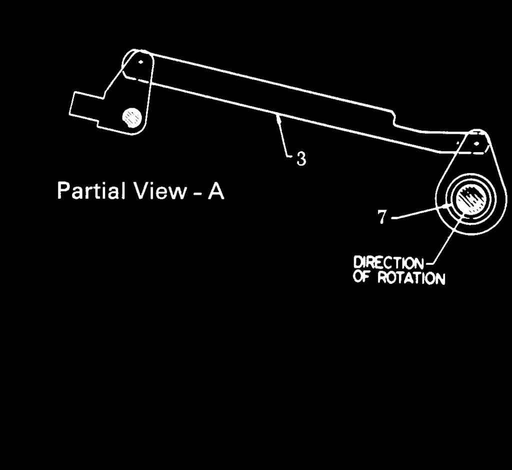
6 Section 3. Description The manual charging system (Fig. 5, View A) (3) works directly on the cam shaft where a one way clutch (Fig. 5, View A) (7) driven by a manual handle provides rotation of the ratchet wheel. Manual pumping of the handle advances the ratchet wheel. and the holding pawl prevents counter rotation while the handle is returning for another stroke. Six to eight complete strokes of the manual handle are required for one complete spring charging operation. WARNING: When the spring charge indicator shows CHARGED manual charging must be discontinued to avoid mechanism damage. The mechanism is mechanically trip-free in any position on the closing stroke. Electrically energizing the trip coil while closing, after the auxiliary switch contacts change position, will rotate the trip latch and permit the circuit breaker to open fully. The linkage will reset as in a normal open operation and the closing spring will recharge. (A) Breaker OPEN Spring DISCHGD 1. Output crank 2. Jack Shaft 3. Trip latch 4. Trip roller 5. Closing roller 6. Trip link 7a. Closing toggle 7b. Closing toggle 8. Prop Latch 9. Closing cam 10. Prop spring 11. Linkage return spring NOTE: Shading indicates fixed pivots (B) Breaker OPEN Spring CHARGED NOTE: Orientation of closing cam (item 9) in view A & C are shown when operated by slow closing. Under normal operation the cam may rotate further in the counter clockwise direction. Figure 3. Toggle Linkage Positions of the ML18/ ML18H Mechanism - View from Right Hand Side (Continued on next page) 6
7 Section 3. Description Distribution Breaker (C) Breaker CLOSED Spring DISCHGD (D) Breaker CLOSED Spring CHARGED Figure 3. (Continued) 7


8 Section 3. Description 3-5 Emergency Trip A Pull To Trip knob is provided on the outside of the mechanism door for emergency tripping of the circuit breaker. When the breaker is tripped by means of this knob, a small lever on the front of the mechanism frame is spring operated to hold the trip button depressed, so that the trip latch cannot reset, and the breaker is mechanically trip-free. The latch check switch (LCS) Fig. 21, is also held open so the closing coil cannot be energized. Provision is made for padlocking the lever in the operated position. As an option, a key lock can also be provided to hold the trip button depressed, and a switch can be added for remote indication of manual trip. After using the emergency trip, the mechanism door must be opened and the lever reset manually to release the trip button. 3-6 Control Circuit A typical ML18/ML18H mechanism wiring diagram is shown in Figure 20. Check the wiring diagram supplied with the actual circuit breaker for its wiring. The mechanism mounted auxiliary switch contacts not used in the control circuit are bought out for control and indication functions. An additional mechanism operated, housing mounted auxiliary switch can be provided for additional contacts. Figure 4. Low Voltage Compartment-Relay Side 8
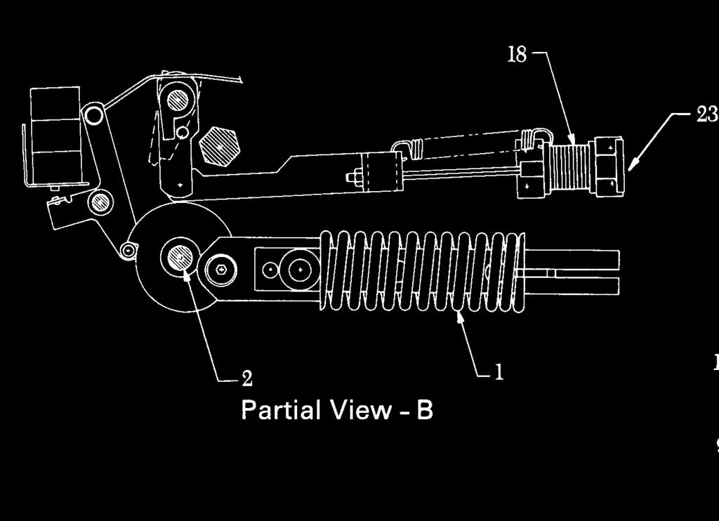
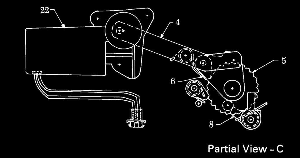
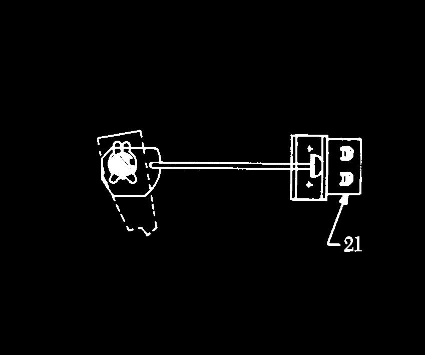
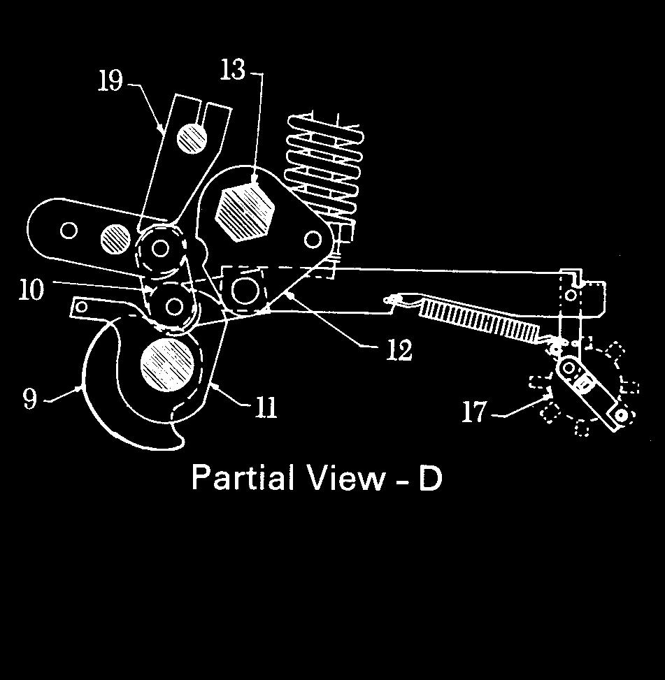
9 Section 3. Description Distribution Breaker Figure 5. Schematic of ML18/ ML18H Mechanism 1. CLOSE SPRING 2. CAM SHAFT 3. MANUAL CHARGE 4. CHARGING ARMS 5. RATCHET WHEEL 6. DRIVING PAWL 7. ONE-WAY CLUTCH 8. CLOSE LATCH 9. CLOSE CAM 10. CLOSE ROLLER 11. PROP LATCH 12. OUTPUT CRANK 13. JACK SHAFT 14. BELL CRANKS 15. OPENING SPRINGS 16. WIPE SPRINGS 17. AUX. SWITCH 18. TRIP SOLENOID 19. TRIP LATCH 20. OVER-TRAVEL STOP 21. LATCH CHECK SWITCH 22. GEAR MOTOR 23. MANUAL TRIP BUTTON 24. GAP ADJUSTING NUT 25. OPEN SPEED ADJ. NUT 26. LOCK NUT (Continued on next page) 9
10 Section 3. Description Figure 5. (Continued) 10


11 Section 3. Description 3-7 Optional Auxiliary Contacts The optional distribution breaker auxiliary contacts are mounted on the mechanism as shown in Figures 6 or 7 (type of mechanism determines which type of auxiliary contacts are installed). Depending on a customer s electrical configuration, a distribution breaker may have up to 2 optional auxiliary contacts in addition to the mechanism auxiliary switch. If adjustments need to be made, follow the adjustment procedure in Section 6 of this document. Optional Aux Contacts Distribution Breaker Figure 6. Distribution Breaker Optional Auxiliary Switches for ML18 type 3 and ML18H type -1 Optional Aux Contacts Figure 7. Distribution Breaker Optional Auxiliary Switches for ML18 type 0, -1, -2 and ML18H type -0 11
12 Section 4. Installation General The installation of the breaker will be facilitated by a study of these instructions and a review of the approved drawings, which supplement these instructions. The drawings show the general arrangement, dimensions (Fig. 8), location of foundation bolts, provisions for conduit connections, electrical connections and other information necessary for the proper installation of the breaker. These drawings consist of the requisition summary, outline of the unit with its operating mechanism and housing, and the connection diagrams. The breaker is shipped in the CLOSED position. 4-1 Location and Mounting The unit should be located so that it is readily accessible for manual operation and inspection. Care should be taken when lifting the unit not to allow the lifting device to come in contact with the bushings. Two lifting holes are provided on the top of the unit for lifting purposes. The total weight of the unit is given on the nameplate and should be taken into consideration when selecting a lifting device for the breaker. Legs for the basic unit as indicated on the outline drawing come in 12 inch to 36 inch lengths and are shipped separately, ready for assembly. After assembly, fasten the breaker in position on its foundation. The foundation should be firm and level; if it is not, shims should be used under the mounting pad of the leg to level the unit. The mounting bolts recommended are inch diameter minimum (0.75 inch diameter bolt can also be used) and their locations are shown on the breaker outline drawings. 4-2 Connections After the breaker has been located, electrical connections can be made. Before making these, every precaution must be taken to see that all leads to be connected to the unit are de-energized. 4-3 Ground Connections The framework of each breaker should be permanently grounded. The usual practice is to connect a heavy cable to the framework and to the ground. Provisions for a bolted connector is provided on the framework (Figure 10) to which the ground cable can be attached. The cable should be sized to carry a minimum of 25 per cent of the current rating of the breaker, but should not be smaller than # 4/0. A good permanent low resistance ground is essential for adequate protection. A poor ground may be worse than no ground at all, since it gives a false feeling of safety to those working around the equipment and may result in injury or damage to the apparatus. 4-4 Control and Secondary Wiring All control wires should be run in conduit insofar as it is practicable. Control wires must be run separately and remote from high tension leads unless the distance separating the two sets of wires is sufficient to prevent possible communication between them as a result of short circuits. Control wiring of adequate size should be used so that with full operating current flowing to the operating mechanism, the voltage across the terminals of the mechanism will be within the limits specified as standard for the control voltage as specified on the nameplate. It is recommended that all conduits entering the mechanism housing be sealed off at their entrances to the housing. Control and bushing current transformer connections are made inside the operating mechanism housing where suitable terminal boards are provided. Connection diagrams are supplied for each unit showing the proper connections for the operating mechanism and the bushing current transformers. All bushing current transformer terminal boards are shipped shorted and grounded. These connections should be changed upon selecting the bushing current transformer ratio. 4-5 Primary Connections Leads should be bought down from above if possible. Ample electrical clearance must be provided between these leads and parts of the station, such as wall, channels and framework. Leads should be properly supported so that the breaker bushings are not subjected to unnecessary strains. The bushings should not carry cable or bus bar strains. To avoid overheating, the connecting leads must be of a current-carrying capacity at least equal to the maximum operating current of the circuit, which should not exceed the breaker rating. Connections to the breaker are made by the bolted connectors fastened to the ends of the bushings and must be securely tightened to assure good contact. All joints must be clean and bright. 4-6 Inspections Before Operation After the unit has been installed with all mechanical and electrical connections completed, the following inspections and tests should be made before operation. If any question arises concerning the unit during the following inspection procedure, refer to Section 6, Measurements and Adjustments. 12


13 Section 4. Installation Distribution Breaker Safety Precautions 1. Check that the unit is properly set up and leveled on its foundation. 2. Check that all nuts, washers, bolts, snap rings, cotter pins and terminal connections are in place and tightened. 3. Visually inspect the circuit breaker for any signs of damage during installation and test it for possible grounds or short circuits. 4. Inspect all insulated wiring to see that it has sustained not damage during installation and test it for possible grounds or short circuits. 5. Check that all bearing surfaces of the operating and breaker mechanisms have been lubricated with 0282A2048P009 grease, furnished with the circuit breaker. 6. Check that all points where the surface of the paint has been damaged during installation are repainted immediately. 4-7 Slow Closing 1. Manually charge the breaker closing spring using the charging handle provided (Fig. 8). The closing spring is charged by a ratcheting mechanism that advances by one ratchet tooth at a time. When the spring is fully charged and the spring load is held by the closing latch the spring indicator will change from ' DISCHGD to CHARGE (Fig. 9), and a positive snap will be heard as the spring travels over center. After the spring is completely CHARGED, as indicated above, further forcing the charging handle may cause damage to the closing latch and its associated parts Manual charging handle 2. Close spring gag hole Figure 8. Manual Charging Handle 2. Insert the closing spring gag plate (Fig. 9) by engaging the detents on the gag plate into the slots on the closing spring guide. With the gag plate in position, depress the manual close button. 1 This action will partially close the vacuum interrupter contact. Do not energize the secondary control circuit at this time. CAUTION: FAILURE TO PUSH THE CLOSE BUTTON BEFORE CONTINUING THE SLOW CLOSE PROCEDURE WILL CAUSE DAMAGE TO THE MECHANISM. 1. CHARGED / DISCHGD Ind. 2. OPEN / CLOSED Ind. 3. Counter Figure 9. Close Spring Gag Plate 4. Manual charging lever 5. Manual Trip Button 6. Trip Lock out 7. Closing spring gag plate 3. To manually slow-close the breaker contacts, insert the manual charging handle in the manual charge slot and move the handle up and down about 6 to 7 times until closing roller (Fig. 5, item 10) is free from the closing cam and resting on the close prop (Fig. 5, item 11). CAUTION: With the gag plate installed, the breaker CLOSED and opening springs CHARGED, the breaker can be tripped at full speed. 4. In the CLOSED position, verify the alignment of the erosion disc and erosion indicator (Fig. 11, items 2 & 4). Check the insulation resistance to ground by connecting a megohmeter between the primary circuit and ground. The minimum resistance should be 10,000 megohms or higher. 5. Keep clear and push the manual trip push-button to trip the breaker open. Check that the position indicator shows OPEN and the operation counter advances one count. Remove the closing spring gag plate. 6. Discharge any stored energy in the breaker by successively depressing the manual close and manual trip buttons. Performing these operations leaves the breaker OPEN with the closing spring DISCHARGED. 13
14 Section 4. Installation 4.8 Electrical Checks Next, the following electrical checks should be made, If required. Electrical checking consists of electrical breaker operation, secondary wiring high-potential testing (if required), primary current path resistance (if required), PowerVac interrupter high-potential testing, and insulation resistance to ground. 1. To check the electrical operation, apply control voltage to the circuit breaker. Check the control voltage on the nameplate and close and open the breaker several times to check electrical operation. CAUTION: Repeated operations at a rate exceeding two per minute may cause charging motor overheating and failure. 2. Perform a vacuum interrupter integrity test to verify the condition of the interrupters. Perform the test as described in Section Perform any of the above mentioned tests as required. Test descriptions can be found in Section Leave the circuit breaker in an OPEN and spring- DISCHGD condition after checks are complete. Figure 10. Breaker Dimensions (1200A & 2000A) (Continued on next page) 14
15 Section 4. Installation Distribution Breaker Figure 10. Breaker Dimensions (1200A & 2000A) (Continued on next page) 15
16 Section 4. Installation Figure 10. Breaker Dimensions (3000A) (Continued on next page) 16
17 Section 4. Installation Distribution Breaker 5. ROOF ENTRANCE BUSHING DIMENSIONS GIVEN IN DRAWING ON PREVIOUS PAGE ARE FOR THE MOST COMMON CURRENT DESIGNS. CONSULT OUTLINE DRAWING SUPPLIED WITH BREAKER TO OBTAIN APPROPRIATE REB DIMENSIONS FOR YOUR BREAKER Figure 10. (Continued) Breaker Dimensions (3000A) 17
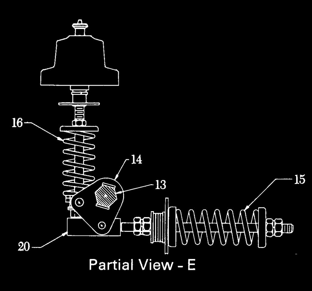
18 Section 5. Operation General The PowerVac vacuum distribution circuit breaker uses a sealed vacuum interrupter to establish and interrupt a primary circuit. Molded supports, one per pole, provide inter-changeable mountings for the primary bars, interrupters, and heat dissipation fins (where used). The operating mechanism provides motion at each pole location in order to move the lower contact of the vacuum interrupters from an OPEN position to a spring-loaded CLOSED position and then back to the OPEN position on command. The ML18/ML18H mechanism is of the stored-energy type and uses a gear motor to charge a closing spring. During a closing operation, the energy stored in the closing spring is used to close the vacuum interrupter contacts, charge the wipe springs which load the contacts, charge the opening springs, and overcome bearing and other friction forces. The energy then stored in the wipe and opening springs will open the contacts during an opening operation. Closing and opening operation are controlled electrically from optional local and/or remote control devices. Mechanical control for maintenance is provided by manual close and trip buttons on the circuit breaker. The closing spring may be manually charged, and a method for slow-closing the primary contacts is available, (See Section 4-7 steps 1 to 3). The mechanism will operate electrically at the ac or dc voltage indicated on the circuit breaker nameplate. Figure 5 shows a front view of the ML18/ML18H in a schematic form. The primary contacts are OPEN and the closing springs CHARGED. The closing spring charging system consists of a closing spring (1) mounted on the left side of the mechanism and electrical charging system mounted on the right side of the mechanism. Both components are fastened to the cam shaft (2). A manual charging system (3) is provided so that the mechanism can be slow-closed and the closing spring can be charged if there is a loss of electrical control power. 5-1 Close Spring Charging Spring charging is accomplished electrically by a rotating eccentric on the output shaft of the gear motor driving pivoted charging arms (Fig. 5, view C) that oscillate about the centerline of a ratchet wheel. (Fig. 5 view C) (5). A driving pawl (Fig.5, view C) (6), mounted within the charging arms, oscillates with the charging arms rotate forward, a spring forces engagement of the driving pawl with a tooth on the ratchet wheel. The ratchet wheel is advanced by the rotating charging arms and pawl assembly. Advancement of one tooth spacing is provided for each oscillation of the system. The ratchet motion is restricted to one direction by a spring loaded holding pawl that prevents the ratchet wheel from going backwards as the charging arms oscillate back to pick up the next tooth. Thirteen (13) complete cycles of the charging arms are needed for a full charge of the closing spring. The efficient, compact gear motor accomplishes this action in just about one (1) second When the charging cycle is complete the ratchet wheel is positioned so that a missing tooth is adjacent to the driving pawl and any motor overspin will not drive the ratchet wheel, thus preventing damage to the system. When the spring is completely CHARGED, the assembly is retained in that position until it is desired to close the circuit breaker. The closing coil cannot be electrically energized unless the closing spring is completely charged. This action is prevented by the 52/CHG switch in the closing circuit. The manual charging system (Fig. 5, view A) (3) works directly on the cam shaft where a one way clutch (Fig. 5, view A) (7) driven by a manual handle provides rotation of the ratchet wheel. Manual pumping of the handle advances the ratchet wheel and the holding pawl prevents counter rotation while the handle is returning for another stroke. Six (6) to seven (7) complete strokes of the manual handle are required for one compete spring charging operation. WARNING: When the spring charge indicator shows CHARGED manual charging must be discontinued to avoid mechanism damage. 5-2 Closing Operation By either energizing the close solenoid or depressing the manual close button, the close latch (Fig. 5, view C) (8) is rotated releasing the closing spring (Fig. 5, view B) (1). This action is transmitted to the closing cam (Fig. 5, view D) (9) and closing roller (10) and causes the linkage to rise until the prop latch(11) can slip under and hold the linkage in place. As the linkage moves the output crank (12) rotates the jack shaft (13) which in turn rotates the phase bell cranks (Fig. 5, view E) (14) on all three poles. The rotation of the phase bell cranks compresses the two opening springs (15) on poles 1 and 3, closes the vacuum interrupters and compresses the wipe springs (16) on each interrupter. The rotation of the jack shaft (13) also changes the auxiliary switch (Fig. 5, view D) (17) position and the position flag on the front panel will indicate CLOSED. After the breaker is CLOSED, the charging motor is again energized and the closing spring is CHARGED as described under Section 5.1 Close Spring Charging. 18
19 Section 5. Operation Distribution Breaker This is possible when the breaker is in the CLOSED position because the linkage is held in position by the prop latch. 5-3 Opening Operation By either energizing the trip solenoid (Fig. 5, view B) (18) or depressing the manual trip button, the trip latch (Fig. 5 view D) (19) is rotated permitting the linkage to collapse and the vacuum interrupter contacts to open under the force of the wipe springs (Fig. 5, view E) (16) and opening springs. At the end of the opening stroke a stop hits the frame and limits over-travel and rebound. Rotation of the jack shaft from the CLOSED to an OPEN position operates the auxiliary switch (Fig. 5, view D) (17) and interrupts the trip coil current. If the closing spring has been recharged the linkage will be reset so that the trip latch will fall in place on the trip roller in preparation for another closing operation. If the closing spring has not been recharged, the trip latch will be held out of position. At latch checking switch (Fig. 5, view C) (21) will not close unless the latch is in its normal position. The contacts of latch checking switch are in the closing circuit so that electrically initiated closing is blocked when the trip latch is not reset. 5-4 Trip-Free Operation The linkage is mechanically trip-free in any location on the closing stroke. This means that energizing the trip coil while closing after the auxiliary switch contacts change position will rotate the trip latch and permit the circuit breaker to open fully. The linkage will reset as in a normal open operation and the closing spring will recharge as described under Close Spring Charging (Section 5-1). 5-5 Control Circuit A typical PowerVac circuit breaker ML18/ML18H mechanism wiring diagram is shown in Fig. 20. Check the wiring diagram supplied with the actual circuit breaker for its wiring. The close spring-charging-motor circuit is established through the CL/MS switch if the close latch is reset and the SM/LS switch if the closing spring is DISCHGD. When the closing spring is CHARGED, the SM/LS interrupts the circuit. The close circuit is established through two normally closed Y relay contacts, 52Y and the latch-checking switch LCS, if the trip latch is reset. An auxiliary switch contact 52 is also in series with the close coil and it closes when the breaker is OPEN and opens when the breaker is CLOSED. During a close operation, cam rotation closes the SM/LS contact, picking up the Y relay coil thereby opening its contacts to interrupt the close, coil current and sealing it in through a normally open contact to the close signal. The sealing prevents re-closing on a sustained close command, as the close signal must be removed to drop out the Y relay, and re-establish the closing circuit, thereby providing an anti-pump feature. The mechanism mounted auxiliary switch contacts not used in the control circuit are brought out for control and indication functions. An additional breaker operated, housing mounted auxiliary switch can be provided for additional contacts. 1. WIPE SPRING ASSEMBLY 2. EROSION DISK 3. LOCK NUT 4. EROSION INDICATOR REF ARM 5. OPERATING ROD EXTENSION 6. OPERATING ROD INSULATOR 7. CLAMP SCREWS 8. COUPLING CLAMP 9. WIPE INDICATOR (ML18 ONLY) Figure 11. Adjustments 19
20 Section 6. Measurements and Adjustments General The ML18/ML18H mechanism has been designed for extended intervals between maintenance. In most cases only the wipe and gap adjustments will require re-setting throughout the life of the circuit breaker. In addition to the descriptions of the adjustments, Table 2 contains a summary of the settings. 6-1 Wipe Adjustment Wipe is the additional compression of a pre-loaded spring, used to apply force to the vacuum interrupter contacts and to provide opening kick-off force. The contact wipe adjustment should always be made before making the contact gap adjustment. See Fig 12 & Fig 21. ML18 Improved accuracy of the wipe measurement may be obtained by using a feeler gauge between the top of the wipe indicator and the erosion disk. The difference in readings on each pole with the breaker closed and open is the contact wipe. Adjustment not required if wipe is more than inch. After adjustment the wipe should be inch. ML18H The wipe measurement is made with the breaker closed and the closing spring gagged. Measure with a feeler gauge the distance between the bellville washer and the trunnion between the bell cranks arms. Adjustment not required if wipe is more than inch. After adjustment the wipe should be inch. The wipe should be set as follows: Breaker Rating Wipe (inches) All Readjust when reduced to To adjust the primary contact wipe, close the breaker. Refer to Fig. 21 for the following wipe adjustment procedure. 1. Loosen but do not remove the two screws (7), holding the interrupter clamp (8). 2. Check that the interrupter clamp is loose. A light pry at the clamp half junction may be required to loosen the wedging action of the clamp. 3. Hold the operating rod extension (5), at the bottom of the operating rod insulator (1 inch wrench) and loosen the adjacent locknut (3/4 inch wrench), item (3). Adjust by rotating the operating rod insulator. The thread is 1/2-13 and each turn will give about inch change in primary wipe. Screw the operating rod insulator toward the interrupter to increase wipe. 4. After setting the contact wipe on each phase, torque the operating rod locknut (3), to foot pounds while preventing the operating rod insulator (6) from turning. Tighten the clamp screws (7) to foot pounds. Trip the breaker OPEN. This procedure prevents accidental twisting of the operating rod of the interrupter by loading the contacts with the wipe springs and forcing relative rotation to occur at the clamp interface. After adjustment, re-measure the wipe for each phase to check the adjustment. If the wipe settings are within the required limits, there is an adequate contact closing relationship between the poles. Refer to Figure Emergency Trip A 'Pull to Trip' knob is provided on the outside of the mechanism door for emergency tripping of the circuit breaker. After using the emergency trip, the mechanism door must be opened and lever reset manually to release the trip button. When properly adjusted, the lever will move across the face of the trip button just as the breaker trips. When it is holding the button depressed, the trip latch must not permit the mechanism to close. A fine adjustment of the trip coil adjusting nut may be required to insure this, See Table 2, adjustment #1 and Fig Primary Contact Erosion Indication In the CLOSED position, the erosion disk (Figure 11, item 2) below the operating rod insulator is aligned with a reference arm (Figure 11 item 4) on new interrupters. As contact erosion occurs, the erosion disk will move upward from alignment with the reference arm. When erosion reaches inch, the PowerVac interrupters should be replaced. NOTE: Do not re-adjust the alignment of the erosion indicator except when installing a new vacuum interrupter. 20
21 Section 6. Measurements and Adjustments 6-4 Contact Gap Adjustment The gap adjustment refers to the separation, or gap, between the primary contacts within the vacuum interrupter. Before attempting to measure or set the gap adjustment, verify that the wipe settings are within acceptable limits. Any change of the wipe settings will affect the gap settings. The method of measuring the contact gap is as follows: With the breaker in the OPEN position, the closing springs charged, and the closing spring gag plate installed, apply a piece of masking tape to the surface of the operating rod insulator as shown in Figure 12. Using a reference block, make a mark on the tape near the top on all three poles. It is also advisable to put a reference mark on the tape to identify to which pole the tape is applied. Remove the closing spring gag plate and close the breaker. Using the same procedure as above, re-mark the tape. This new mark will be near the bottom of the tape. Trip the breaker, remove the tapes and re-apply them to a flat surface. Measure the distance between the two lines. NOTE: Reference block may be obtained from GE by ordering part number 0348A3404P Adjust the outer left and right phases first. The contact gap must be The adjustment of the outer phases affects the center phase measurement. With the breaker in the OPEN position and the closing spring DISCHGD, locate the gap adjusting nuts on the opening spring rods connected to the outer phase bell cranks (Figure 21). Loosen the jam nut on both rods. Back off the adjusting bolt on the center phase VI stop (Figure 21) Advance or retard the adjusting nuts depending on which way you want to change the gap. Move both nuts the same amount. 3. Lock the jam nuts after setting the adjusting nuts. Operate the breaker a few times and re-measure the gap. 4. Readjust the center phase VI stop (Figure 21). Set adjusting screw for no clearance between stop and wipe spring rod striker with the breaker open. After adjustment of the left and right phase, re-measure the center phase. The center phase should not exceed 0.60 inch. If it does, then readjust the left and right phase gaps. REFERENCE BLOCK Figure 12. Gap Measurement 21
22 Section 6. Measurements and Adjustments 6-5 Control Coil Plunger Travel Trip Coil With the breaker in the OPEN position and the closing spring in the CHARGED position, make certain that the trip linkage and trip shaft move freely over the full plunger travel, (Fig. 19). Some breakers due to the customer s application are equipped with two trip coils (optional), (Fig. 19). Sequence of operation of dual trip coils is determined by the customer. Close Coil With the closing spring DISCHGD, operate the plunger in the same manner described above for the trip coil. Make certain that the plunger moves freely over its full stroke in the coil, see Figure Control Switches There are three switch locations on the ML18/ML18H mechanism. The CL/MS closing latch monitoring switch (Figure 23, item 13), is to the rear of the ratchet wheel and is operated from the closing latch. The SM/LS spring motor limit switches (Figure 23, item 11) control the spring charging motor and the anti-pump relay. The 52 charge switch, which is in the same location can be used for remote indication of the CHARGED condition of the spring. The LCS latch checking switch (Figure 23, item 12), monitors the position of the trip latch. The switches are adjusted as described in Table 2 Items 7 and 8. 1 Gap between 3 and 4 is no greater than 1/ Gap between links 1 and 2 is no greater than.005 Figure 13. Specification for Aux Switch Linkage 2 Breaker in Open and Discharged Position 1. DRIVE LINK 3. AUX SWITCH LINK 2. LINK 4. STOP 6-7 Optional Auxiliary Contacts The optional auxiliary contacts should be checked for operation within specification at the regular distribution breaker maintenance interval of 2,000 mechanism operations. Adjustment to the breaker wipe and gap will affect auxiliary switch adjustment, therefore, adjustments to the auxiliary switch (es) must be made only after wipe and gap adjustments are complete. ML18 Type 3 and ML18H Type 1 The specification for the auxiliary switch linkages is shown in (Figure 13). Check the auxiliary switch linkages with feeler gages to ensure that the two items illustrated in (Figure 13) are within specification. If linkages are not within specification then proceed to next paragraph. 22


23 Section 6. Measurements and Adjustments 1. Disconnect charge motor power by disconnecting motor leads shown in Fig Charge the breaker and subsequently depress the Close button followed by the Trip button. Confirm the indicators show Open and Discharged. 3. Locate the bolt coupling the linkage cranks. Fig Loosen (do not remove) nut from bolt with (2) ¾ open end wrenches. Motor Leads 5. Move the linkage crank relative to the stationary crank until the specified adjustment is attained. 6. Tighten the nut onto the bolt to ft-lbs torque using a torque wrench with ¾ crow s foot adapter and a ¾ open end wrench. 7. Manually charge the breaker, depress the Close then Trip buttons, and re-inspect the auxiliary switch linkages per Section 3 of this document. Figure 14. Charge Motor Connector Bolt 8. Apply 0282A2048P009 grease to all moving parts. 9. Reconnect charge motor leads. Figure 15. Linkage Crank Coupler Nut & Bolt Stationary Crank Adjustment Slot Linkage Crank Figure 16. Outline of Linkage Cranks 23
 is present between the paddle on the breaker and the arm of the auxiliary switch. Adjust gap by moving position of mounting plate from left to right.")

24 Section 6. Measurements and Adjustments ML18 Type 0, -1, -2 and ML18H Type -0 Adjust the position of the switch so that a small gap (about ) is present between the paddle on the breaker and the arm of the auxiliary switch. Adjust gap by moving position of mounting plate from left to right. Close the breaker and inspect the operating lever to ensure it is touching the overtravel stop (Figure 5). Using a felt tip pen, mark a reference line on the over-travel link. Open the breaker and inspect for amount of overtravel. The over-travel should measure between 1/8 to 1/4". Adjust position of mounting plate to increase or decrease the gap between the breaker paddle and auxiliary switch arm to decrease or increase overtravel respectively. Charge the closing spring, close the breaker and mark a new reference line. Open the breaker to reinspect. Over-travel link Reference Line Actuation Level MARK LINE W/BREAKER Over-travel link /8-1/4 Figure 17. Paddle- Arm Gap Measurement Actuation Level (over-travel) (no over-travel) Figure 18. Auxiliary Switch Over-travel Check 24
25 Section 6. Measurements and Adjustments Figure 19. Trip Coil and Linkage 25
26 Section 6. Measurements and Adjustments Figure 20. Typical Wiring Diagram for ML18/ML18H Mechanism 26
27 Section 7. Electrical Checks Distribution Breaker 7-1 Control Power When a capacitor trip device is supplied; make certain that the tripping circuit is not completed (all protective relay contacts open) when applying a-c voltage to a discharged unit. After the breaker has been operated several times with the manual charging lever and the mechanism adjustments are checked as described, the closed circuit operating voltages should be checked at the close coil, trip coil, and motor terminals. Control power for electrical operation of the breaker maybe from either an alternating or direct current source. The operating ranges for the closing and tripping voltages as given on the breaker nameplate, are listed in Table 1 below. If the closed circuit voltage at the terminals of the coil or motor does not fall in the specified range, check the voltage at the source of power and line drop between the power source and breaker. When two or more breakers operate from the same control power source are required to close simultaneously, the closed circuit voltage at the closing coil or motor of each breaker must fall within the specified limits. 7-2 Timing Timing and speed checks are optional and also depend on the level of maintenance performed. Generally these tests are not required for normal maintenance. If a new mechanism has been installed or extensive repair, replacement or major disassembly has been performed, it is recommended that these tests be performed. To determine contact velocity, a travel recorder and oscillograph are required. Optional travel recorders can be obtained through your local GE Sales Office by ordering part number 0144D1235G001. A typical travel trace and interpretation are shown in Figure 25. Timing may be checked by monitoring control circuit voltage and using no more than six volts DC and one ampere through the vacuum interrupter contact to indicate CLOSED or OPEN condition. Typical time ranges vary with coil voltage, but nominal values are: Initiation of trip signal to contact parting Milliseconds (5 cycle) Milliseconds (3 cycle) 2 Millisecond maximum pole spread Initiation of close signal to contact closing Milliseconds 2 Millisecond maximum pole spread Trip-free operation may be checked by applying a simultaneous close and trip signal and a minimum reclose operation may be checked by tripping a charged breaker open while maintaining a close signal. Instantaneous re-close time* Milliseconds *Time from application of trip signal until breaker opens and re-closes. 7-3 Opening and Closing Speed The opening speed is modified by tightening or loosening the speed adjustment nuts on the opening spring assemblies. A change in the opening speed affects the closing speed. Refer to Fig 21 & Fig 25. The operating speeds are as follows: Operation Open Close Feet Per Second 5.0 nominal, 4.5 minimum 3.5 nominal, 4.0 maximum Table 1. Control Devices and Voltages Control Voltage Source Closing range Tripping Tripping coil current range Tripping coil current 5 cycles 3 cycles Motor Inrush current Motor Windup current 48 VDC VDC VDC VAC VDC VAC VDC* *Capacitor trip, 240 VAC requires the capacitor trip to operate a 340-trip coil. 27
28 Section 7. Electrical Checks Figure 21. Mechanical Adjustments and Settings (Continued on next page) 28
 ML18 TYPE 2 and 3 ML18H TYPE 0 and -1 CLMS SWITCH ML18H TYPE 0 and 1")
29 Section 7. Electrical Checks Distribution Breaker SHIM PLACEMENT NO ADJUSTMENT LCS SWITCH (Post 1998) ML18 TYPE 2 and 3 ML18H TYPE 0 and -1 CLMS SWITCH ML18H TYPE 0 and 1 ML18 TYPE 2, -3 STACK SWITCH LCS SWITCH, ML-18 TYPE 0, -1 CLMS SWITCH ML18 TYPE 0 and -1 Figure 21. (Continued) Mechanical Adjustments and Settings 29
30 General PowerVac circuit breakers have been designed to be as maintenance free as practicable. They include features such as sealed vacuum interrupters and long life synthetic greases which contribute to many years of trouble free performance with a minimum amount of maintenance attention. WARNING: Before any maintenance work is performed make certain that all control circuits are de-energized. Do not work on the breaker or mechanism while it is in the closed position without taking precautions to prevent accidental tripping. Do not work on the breaker while the closing spring is charged, unless the spring is gagged. 8-1 Service Conditions The frequency of required maintenance depends on the severity of the service conditions of the circuit breaker application. If the service conditions are mild, the interval between maintenance operations may be extended to 10 years or 2,500 normal load switching operations. Mild service conditions are defined by ANSI standards as an environment in which the circuit breaker is protected from the deleterious effects of conditions such as: Salt atmosphere Changes in temperature that produce condensation Conductive and/or abrasive dust Damaging chemicals and fumes Vibration or mechanical shock High relative humidity (90%) Temperature extremes (-30 C, 40 C) WARNING: Before any maintenance work is performed, make certain that all control circuits are de-energized. 8-2 Fault Interruptions The erosion rate of the primary contacts in the vacuum interrupters is very low for no load and normal load switching operations. However, fault current interruptions at or near the breaker rating may result in appreciable contact erosion. With frequent fault interruptions it is necessary to perform maintenance based on the number of interruptions. After each 8 fault interruptions the following should be performed. 1. Contact erosion per Section Wipe and gap per Table 2 Items 4 & Vacuum Interrupter Integrity Test (Section 8-8). 8-3 PowerVac Interrupter The PowerVac interrupter used in this breaker is a reliable, clean interrupting element. Since the contacts are contained in a vacuum chamber, they remain clean and require no maintenance at any time. The metallic vapors eroded from the contact surfaces during high current interruption remain in the chamber and are deposited on metal shields thus insuring a high dielectric value of the vacuum and the walls of the glass/ceramic container. 30 Section 8. Maintenance 8-4 Trouble Reporting Although all reputable manufacturers design their products to perform satisfactorily with minimum problems, the IEEE Switchgear Committee, an organization of both users and manufacturers, recognize the need for a common trouble reporting format. A reproducible copy of this form is included inside the rear cover of this book and is recommended for use with any manufacturer s circuit breakers. The intent is for each maintenance organization to keep specific problem files with this information documented. If the problem is serious or repetitive, a summary should be sent to the appropriate manufacturer for action. The level of detail included on the form is considered very desirable so that the manufacturer s investigator may more thoroughly understand and solve the reported problem. 8-5 Contact Erosion Check in the breaker-closed position per Primary Contact Erosion Indication (Section 6-3). When erosion reaches inch, the interrupter should be replaced. 8-6 Transfer Finger Wear Examine the moving contact rod projecting below the transfer finger with the breaker OPEN, wiping off the lubricant in order to see the metal surface condition. The contact locations should present a burnished silver surface without copper appearance at more than one location. If copper is visible at more than one location per pole or the silver plating is torn, the interrupter assembly should be replaced. Re-lubricate movable contact rod with 0282A2048P009 grease. 8-7 Insulation Tests The primary circuit insulation on the breaker may be checked phase to phase and phase to ground using a 2500V megohmeter. To measure the breaker secondary circuit insulation resistance, remove the motor leads, and thread a wire connecting all secondary terminals together. The measurement may be made by connecting a 500V megohmeter from the wire to ground. Since definite limits cannot be given for satisfactory insulation value, a record should be kept of the megohmeter readings as well as temperature and humidity readings. This record should be used to detect any weakening of the insulator from one check period to the next.
31 8-8 High-Potential Test If high potential tests to check the integrity of the primary insulation are required, the AC high potential test described below is strongly recommended. DC high potential testing is not recommended. The following procedure must be adhered to. CAUTION: IF DC HIGH POTENTIAL TESTING IS USED, THE DC HIGH POTENTIAL MACHINE MUST NOT PRODUCE PEAK VOLTAGES EXCEEDING 50 kv. NOTE: Always recheck with an AC tester if initial results are questionable. Primary Circuit The breaker should be hipotted with the breaker closed. An AC hipot machine capable of producing the test voltages shown below may be used to hipot the breaker phase to phase and phase to ground. BREAKER VOLTAGE AC TEST VOLTAGE 15.5 kv 37.5kV (RMS) The machine should be connected with its output potential at zero and the voltage increased at 500 volts per second to the test voltage and that voltage maintained for 60 seconds. The voltage should then be returned to zero and the test leads removed from the circuit and the breaker discharged to ground. NOTE: Do not exceed the test voltage indicated for the applicable breaker voltage rating. If the test should experience a failure, STOP, turn off the test set and discharge the breaker circuit. 1. Check the test set up and leads for connection errors. 2. Wipe down the breaker to remove any moisture, dust and contamination. 3. Retest the breaker at the proper test voltage. Secondary Circuit Prior to hipotting the breaker secondary circuit, disconnect the motor leads, thread a wire connecting all secondary terminals together. Connect the hipot machine from this wire to ground. Increase the voltage to 1125 volts rms, 60-Hz and maintain for 60 seconds. Reduce the voltage to zero and remove the hipot machine from the circuit. Remove the wire connecting the secondary terminals and reconnect the motor leads. 8-9 Vacuum Interrupter Integrity Test A vacuum integrity test of the interrupter is required to ensure that no loss of vacuum has occurred. The vacuum integrity test is performed using an AC hipotential tester. This test of the vacuum interrupter will Section 8. Maintenance Distribution Breaker determine its internal dielectric condition and vacuum integrity. With the breaker OPEN, individually check each interrupter by connecting the hi-pot machine Hot lead to the primary bus bar and the ground lead to the load side bus bar. If the machine has a center point ground, the connections can be made either way. Apply 36 kv (rms) 60 Hz at 500 vps and hold for 10 seconds. If no breakdown occurs, the interrupter is in acceptable condition. After the high potential voltage is removed, discharge any electrical charge that may be present through the internal ground of the test machine or by a grounded cable to one of the phase bus bars. NOTE: Use of a DC hipot is not recommended, but can be used for quick field checks only. DC testers frequently yield false negative test results, due to the capacitive component of the vacuum interrupter during DC testing; in addition most lightweight DC testers have a very low leakage current trip setting. Always recheck with an AC tester if initial results are questionable. Prior to performing any vacuum interrupter integrity test, the outside (external surface) of the vacuum interrupters should be wiped clean of any contaminates with a non linting cloth or industrial type wiper. This is critical: the entire external surface is to be completely free of all dirt, debris, dust, oil, etc. CAUTION: X-RADIATION WILL BE PRODUCED IF AN ABNORMALLY HIGH VOLTAGE IS APPLIED ACROSS A PAIR OF ELECTRODES IN A VACUUM. X-RADIATION WILL INCREASE AS VOLTAGE INCREASES AND/OR AS CONTACT SEPARATION DECREASES. ONLY TEST A CORRECTLY-ADJUSTED CIRCUIT BREAKER. DURING A HIGH POTENTIAL OR A VACUUM INTEGRITY TEST, ANY X-RADIATION WHICH MAY BE PRODUCED WILL NOT BE HAZARDOUS AT A DISTANCE SAFE FOR HIGH POTENTIAL TESTING, IF THE TEST IS CONDUCTED AT THE RECOMMENDED VOLTAGE AND WITH THE NORMAL OPEN CIRCUIT BREAKER GAP. DO NOT APPLY VOLTAGE THAT IS HIGHER THAN THE RECOMMENDED VALUE. DO NOT USE CONTACT SEPA-RATION THAT IS LESS THAN THE RECOMMENDED OPEN-POSITION BREAKER CONTACT GAP. If a failure of a vacuum bottle should incur during the integrity test, the test procedure should be reviewed and the pole piece cleaned. GE failure rate for vacuum bottles is per field unit. 31
32 Section 8. Maintenance CAUTION: MANY DC HIGH POTENTIAL MACHINES ARE HALFWAVE RECTIFIERS. THIS TYPE OF HIPOT TESTER MUST NOT BE USED TO TEST VACUUM INTERRUPTERS. THE CAPACITANCE OF THE POWERVAC BOTTLES IS VERY LOW AND THE LEAKAGE IN THE RECTIFIER AND ITS DC VOLTAGE MEASURING EQUIPMENT IS SUCH THAT THE PULSE FROM THE HALFWAVE RECTIFIER MAY BE IN THE NEIGHBORHOOD OF 120 kv WHEN THE METER IS ACTUALLY READING 40 kv. IN THIS CASE, SOME PERFECTLY GOOD BOTTLES CAN SHOW A RELATIVELY HIGH LEAKAGE CURRENT SINCE IT IS THE PEAK VOLTAGE OF 120 kv THAT IS PRODUCING ERRONEOUS BOTTLE LEAKAGE CURRENT. IN ADDITION, ABNORMAL X-RADIATION WILL BE PRODUCED. Note the voltage level at failure on the first test, and retest the phase pole piece. If the pole piece passes test, the vacuum bottle is acceptable - STOP. If the test fails again but at a higher voltage level than was observed in the first test, clean the pole piece and retest. If a failure of the integrity test occurs a third time, consider the vacuum bottle to have lost vacuum and replace the complete pole piece as described under Repair of Interrupter Assembly Although a AC hi-potential test is strongly recommended for checking the vacuum integrity, DC hi-potential test sets are frequently used. If a DC Hi-potential test set is to be used, test voltage should not exceed 50kV DC, and should be applied for 10 seconds. Interrupters must be cleaned as previously discussed. If failure occurs, reverse the polarity and retest. If the interrupter passes the second test, STOP. The interrupter is acceptable. If the interrupter fail the second test, we recommend a final test with an AC Hi pot before replacement. No attempt should be made to try to compare the condition of one vacuum interrupter with another nor to correlate the condition of any interrupter to low values of dc leakage current. There is no significant correlation. After the high potential voltage is removed, discharge any electrical charge that may be retained. An acceptable AC high potential machine is available from: GE Company, Burlington, Iowa, Catalog Number 282A2610P001 Acceptable AC high potential machines are: Hipotronics Model 7BT 60A Hipotronics Model 60HVT James G. Biddle Catalog Acceptable DC high potential machines are: Hipotronics Model 860PL Hipotronics Model 880PL GE/Programma VIDAR 8-10 Primary Circuit Resistance A resistance check of the primary circuit may be made with the breaker closed. Use a low resistance measuring instrument which measures microhms. The D-C resistance of the current-carrying circuit from bushing top terminal to building top terminal of each pole unit in the closed position should not exceed the values tabulated below. Breaker Cont. Microhms Current Rating New After service 600 A A A Power Factor The overall GST (Grounded Specimen Test) can be performed on the bushing of vacuum distribution circuit breakers in the same open-breaker test procedure used for oil circuit breaker. These tests are rated on the basis of dielectric-loss. The power factor for each bushing of porcelain design is tested at room temperature, 23 degrees C, and should not exceed 3%. Power factor testing of the vacuum interrupter is not recommended because of the low charging currents. The Watt-loss measurement across the open vacuum interrupter bottle is not meant to be a direct measure of the dielectric-breakdown strength of the interrupter. While defective bottles with improper vacuum or high-loss conditions on the internal or the external surfaces have been detected, separable identification is not easy and the readings have not proven to be consistent. For accurate verification of the loss of vacuum integrity in a bottle, perform an AC hi-potential test as described in section Mechanism Check all items on Table 2, Summary of Adjustments and Critical Dimensions, re-adjusting or tightening as required. Lubricate as recommended under LUBRICATION (Section 8-14) Primary Insulation Parts Using dry non-linting cloth or industrial-type wipers, clean accessible insulation surfaces on the interrupter supports and operating rod insulators. In service locations where contamination is heavy or external flashovers have occurred during interrupter high potential testing, clean the inside surface of the interrupter supports and the outer surface of the PowerVac interrupters. Remove the interrupter assembly, if necessary, per the procedure in REPAIR AND REPLACEMENT (Section 9-2) and be sure to discharge the interrupter midband ring (glass bottle only, see fig. 26a) before removing the interrupter assembly. Removal and re-installation of interrupter assemblies will normally not require readjustment due to the design of the interrupter operating rod insulator connection. They should be returned to the same location from which they were removed. 32
33 8-14 Lubrication Proper lubrication is important for maintaining reliable circuit breaker performance. The ML18/ML18H mechanism used bearings, which have a synthetic lining in some locations. These bearings do not require lubrication to maintain low friction, but lubrication does not harm them and oiling lightly is recommended. Sleeve bearings are used in some linkage locations and needle or roller bearings are used for low friction on trip shaft and close shaft. Bearings are lubricated during factory assembly with grease and oil, but all lubricants have a tendency to deteriorate by oxidation or contamination with age. Providing a fresh lubricant supply at periodic intervals is essential to proper breaker operation, especially where frequent operation may have forced lubricant out of the bearing surfaces. Section 8. Maintenance Distribution Breaker 8-15 Recommended Maintenance The following operations should be performed at each maintenance. 1. Perform a visual inspection of the breaker. Check for loose or damaged parts. 2. Perform the slow closing operation described in Section 4-7, step Check the erosion indicator and the wipe and gap as described in Sections 6-3 and Perform the vacuum interrupter integrity test as described in Section Lubricate the breaker operating mechanism as described on this page. Apply a few drops of light synthetic machine oil such as Mobil 1 at each bearing. Apply a coat of 0282A2048P009 on the four corners of the closing spring guide where it enters inside the spring. Electrical primary contact surfaces also require periodic lubrication to inhibit oxidation and minimize friction. At each inspection and maintenance interval, the metal contact surfaces of the movable contact rod of the interrupter should be lubricated with 0282A2048P009. This grease is available packaged in a pint can. 6. Check the electrical operation. 7. Examine the movable contact rod of the vacuum interrupter for wear as described in Section If desired, perform the additional electrical tests (Megger, primary and secondary high-potential and primary circuit resistance and vacuum interrupter integrity test). See Sections 8-7 to
34 Section 8. Maintenance Table 2. Summary of Adjustments and Critical Dimensions Item Breaker Position Closing Spring Opening Spring Adjustment Detail 1. 1 st & 2 nd Trip coil (See Section 6.5) Closed Discharged Charged 2. Close coil (See Section 6.5) Open Charged Discharged 3. Wipe (See Section 6.1) 4. Gap (See Section 6.4) Closed Open Charged And Gaged Discharged Charged Discharged 1. Depress coil plunger until trip pin on actuator arm just makes contact with trip arm. 2. Check that gap between coil assy. & plunger base is Turn adjusting nut to meet setting, bend clip over after final setting. 1. Depress coil plunger until latch actuator just makes contact with close latch pawl. 2. Check that gap between coil assy. & plunger base is Turn adjusting nut to meet setting, bend clip over after final setting. 1. Turn operating rod to achieve a.160 to 180 gap between trunnion block & bellville washers. 2. Tighten locknut. 1. Set adjusting nut so that gap is Check that trip latch will reset. 3. Adjust gap if trip latch will not reset. 5. Stack Switch assembly (See Fig 21) Open Discharged Discharged 1. With adjusting bolts loose, hold.020 spacer between actuator roller and crank. 2. Slide support bracket until plunger is fully depressed. 3. Tighten adjusting bolts. 6. V.I. Stop (See Fig 21) Open Discharged Discharged 7. LCS Switch (See Section 6.6) Open Discharged Discharged 8. CLMS Switch (See Section 6.6) Open Discharged Discharged 1. Set adjusting screw for no clearance between stop and wipe spring rod striker. 1. Adjust mounting of switch for visual flush to.031 recess of plunger at back of switch. 1. Adjust position of CLMS switch to open with start of travel of close latch. 9. Erosion indicator (See Section 8.5) Closed Discharged Charged 1. Bend erosion indicator tab to be in line with disc on wipe spring assembly. Only perform this adjustment upon replacement of VI Stop or pole assembly. 34
35 General The following information covers in detail the proper method of removing various parts of the breaker in order to make any necessary repairs. This section includes only those repairs that can be made at the installation on parts of the breaker that are most subject to damage or wear. 9-1 Renewal Parts It is recommended that sufficient renewal parts be carried in stock to enable the prompt replacement of any worn, broken, or damaged parts. A stock of such parts minimizes service interruptions caused by breakdowns, and saves time and expense. When continuous operation is a primary consideration, more renewal parts should be carried, the amount depending upon the severity of the service and the time required to secure replacements. Renewal parts, which are furnished, may not be identical to the original parts, but they will be interchangeable. A separate Renewal Parts Bulletin is available from your local GE Sales office by asking for GEK Replacement of Interrupter Assemblies Interrupters are supplied as pole units, which include the vacuum interrupter, mounted in the interrupter support. CAUTION: Do not attempt to remove or re-insert the vacuum interrupter in the interrupter support assembly. Special tools available only at the factory are required. 1. Disconnect riser bus from vacuum interrupter studs extending from Breaker. 2. Close the breaker and remove the interrupter clamp, (4) Fig. 11. Open the breaker and remove the four bolts holding the pole assembly to the mechanism and remove the old pole assembly. 3. Set the new pole assembly in place and install the four mounting bolts. 4. Close the breaker using the Slow Closing Operation. Perform the closing operation slowly while guiding the tip of the operating rod into the base of the movable contact rod on the vacuum interrupter. After the breaker is fully closed install the coupling clamp. 5. Check and adjust the erosion indicator (3) Fig. 11 (if new interrupter assembly is installed), and the Wipe and Gap as described in Table 2, Items 4 and 5. Distribution Breaker Section 9. Repair and Replacement 6. Reconnect riser bus, tighten bolts. Torque to 35 ftlb. 7. Perform the Vacuum Interrupter Integrity test. 9-3 Pin Retaining Rings These rings are widely used in the ML18/ML18H mechanism to retain pins. They can be installed and removed with a pair of standard pliers. DO NOT REUSE after removal. To remove, slowly squeeze the removal ears while pulling, To install, position on the pin groove and squeeze the installation ears closed to not more than 1/16 inch gap between ears. 9-4 Control Switches Control switches may be removed from their mounting brackets by disconnecting the wires and removing the two mounting screws. Use a small screwdriver to remove and replace the switch on the bracket checking that the correct type, normally open or normally closed, is used. Re-install wire and adjust per Section 6.6, Control Switches. 9-5 Trip Coil Replacement Tools Required 5/16 Allen wrench - 9/16 combination end wrench - 7/16 socket - 7/16 combination wrench - 1/4 square drive ratchet - 1/4 square 3 extension - Loctite #271 or equivalent - Needle nose pliers Perform the operation in the following sequence: 1. Charge closing spring and install gag plate. 2. Depress the close and then the trip buttons. 3. Pump the manual close handle 3-4 times to transfer all remaining spring pressure from the spring crossbar to the gag plate. 4. With the 5/16 Allen wrench remove the pivot bolt (10), Figure 23, and the closing spring (1), Figure Then remove the spring crossbar and its support plate by removing the two 3/8 bolts retaining it. 6. Disconnect the trip linkage tension spring. 7. Remove the bolts from the coil bracket leaving the two bolts nearest the front in place in the mechanism plate. 35
36 8. The trip coil and armature can now be removed by cutting the coil leads. To install the new coil connect leads with insulated butt connectors and reverse the above procedure. See Table 2, Item 1 for setting the stroke of the armature. Apply Loctite to the threads of the pivot bolt when it is replaced. See Section 6, Measurements and Adjustments for setting the stroke of the armature. Charge the breaker, remove the gag plate, then electrically close and trip it to make certain it has been reassembled correctly. 9-6 Closing Coil Replacement Remove the closing coil housing (6), Figure 23. Disassemble the closing armature and closing coil. Cut the leads to the closing coil and remove the coil. Butt splice the new coil into the wiring harness and reassemble the coil and housing. Readjust the closing coil armature travel in accordance with instructions in Table 2, Item Entrance Bushing Removal In the event that an entrance bushing must be removed, the current transformer on that bushing must first be removed to allow the removal of the grounding spring. The grounding spring is a long coil spring hooked together at the ends to form a garter, which is passed up over the bushing ground sleeve. Within the coil spring is a bare conductor, the ends of which come out of the spring and are terminated in a single terminal. The terminal is anchored to the roof frame. The terminal must be Section 9. Repair and Replacement disengaged and the garter removed before the bushing is removed. The procedure is reversed for reinserting a bushing. The ground sleeve is referred to above is in the form of a conductive coating applied directly to a section of the lower end of the bushing. The garter make s electrical contact with the ground sleeve and the conducting leads terminated in the terminal complete the connection to ground potential. NOTE: Upon completion of any kind of repair work, all interrupter and mechanism adjustments must be checked. Refer to the sections on Mechanical and Electrical Adjustment. Ordering Instructions 1. Always specify the complete nameplate data of both the breaker and mechanism. 2. Specify the quantity, catalog number (if listed), reference number (if listed), and description of each part ordered, and the parts bulletin number. 3. Standard hardware, such as screws, bolts, nuts, washer, etc. is not listed in this bulletin. Such items should be purchased locally. 4. For prices or information on parts not listed in the Renewal Parts Bulletin, refer to the nearest GE office. 9-8 Breaker Removal Kit number 0282A6539G001 should be installed to facilitate safe removal of the breaker. Figure 22. Closing Coil and Linkage 36

37 Section 9. Repair and Replacement Distribution Breaker Closing Spring 9. 52Y Relay 2. Opening Spring 10. Pivot Bolt 3. Auxiliary Switch 11. SM/LS Motor Control Switch 4. Spring Charging Motor 12. LCS Latch Checking Switch 5. Trip Coil 13. CL/MS Closing Latch 6. Closing Coil 14. Optional contacts switch operator 7. Ratchet Wheel 15. Close latch adjustment screw 8. Closing Cam Figure 23. Bottom View of ML18/ML18H Spring Charged Mechanism Auxiliary Switch Replacement With the breaker open and the closing spring discharged, remove retaining clip from auxiliary switch shaft, or loosen clamping bolt in operating link. Remove mounting hardware securing auxiliary switch to mechanism plate. Slide auxiliary switch and shaft out of operating link. Before removing any wires from switch terminals, make sure they are properly tagged with switch terminal numbers to assure proper placement on new switch. Remove wires. To install new switch, attach leads then install switch, or install switch then attach leads depending upon type of switch and its terminal accessibility. Install switch shaft in operating link with index mark aligned as shown in the figure. Reverse above procedure to complete installation Index Mark 2. Stopper 2 Figure 24. Auxiliary Switch Position 37
38 Section 9. Repair and Replacement 9.10 Motor Replacement With the breaker open and the closing spring discharged, remove auxiliary switch as described above but do not disconnect leads. Move switch toward side of mechanism far enough to clear motor and tie there temporarily. Disconnect motor leads. Remove the long bolt and spacer securing the motor to the mechanism mid-plate. Remove the two socket head cap screws securing the motor to the mechanism top plate using a 5/16 Allen socket and a 24 extension. Disengage the motor output shaft from the charge linkage arms and withdraw motor. To install the new motor, reverse the above procedure Y Relay Replacement Before removing the Y relay, make sure all leads are marked with terminal locations. Next, disconnect all leads and remove the two fasteners securing the Y relay s shock absorbing mounting bracket to the mechanism rear plate. Withdraw relay and bracket. Remove fasteners securing relay to mounting bracket. Reverse the above procedure to install new relay Close Latch Stop Bolt All distribution circuit breakers utilizing ML18 mechanisms with a type designation ending in -0 or -1 have an adjustment bolt on the close latch. The adjustment for the close latch stop bolt is made with the breaker open and the closing spring charged. 1) Turn the ¼-20 adjusting bolt in against the close latch until the closing spring discharges and the breaker closes. 2) Back out bolt ½ turn (three flats on head of bolt) 3) Check for proper holding of the latch on recharging of the closing spring. If latch fails to reset and hold the spring, back the bolt out 1 or 2 additional flats Dashpot Adjustment-(If Equipped) Dashpot adjustment to be.781 +/-.030 when breaker is in the open position (See Figure. 28). Dashpot is a sealed unit, no maintenance is required. Replace dashpot in case of any leakage Optional Auxiliary Contacts Parts and Tools Required Required Parts Part Number 0282A2048P009 Required Tools (2) 3/4 Open End Wrenches (1) lb-ft Torque Wrench (1) 3/4" Crow s Foot Adaptor (1) Set of Feeler Gages Description Breaker Grease All distribution circuit breakers utilizing mechanism ML18-2, ML18-3, ML18H-0 or ML-18H-1 have no adjustment bolt on the close latch. A permanent stop with no adjustment is provided by a pin attached to the mechanism side. 38
39 Section 9. Repair and Replacement Figure 25. Sample Operating Speed Graphs 39


40 Section 9. Repair and Replacement Metal-to-Insulation Vacuum Seal Stationary Electrical Terminal Vacuum Chamber Electric Arcing Region Electrical Contacts Midband Ring Insulating Vacuum Envelope Flexible Metallic Bellows Shield Metal Vapor Condensing Shield Movable Electrical Terminal Metal-to-Insulation Vacuum Seal Figure 26a. Vacuum Interrupter Assembly (Glass Type) Figure 26b. Vacuum Interrupter Assembly (Ceramic Type) 40
41 Section 9. Repair and Replacement SEE NOTE 3 Figure 27. Travel Recorder Auxiliary Linkage NOTE: 1. ATTACH TRAVEL RECORDER BRACKET TO THE BREAKER FRAME AND IN LOCATION OF ARROWS, WITH THE VISE-GRIPS PLIERS. 2. SLIDE LINK OF TRAVEL RECORDER ONTO EROSION INDICATOR DISK AND TIGHTEN BOLT. 3. TRAVEL RECORDER KIT PART NUMBER 0144D1235G001 (Refer: GEK-90218B Renewal Parts). NOTE: 1. DASHPOT ADJUSTMENT TO BE.781 +/-.030 WHEN BREAKER IS IN THE OPEN POSITION (AS SHOWN). Figure 28. Opening Dashpot 41
42 Intentionally left blank 42
43 FAILURE REPORTING FORM FOR POWER CIRCUIT BREAKERS USER REPORT NO. Check all appropriate blocks and provide information indicated. For major trouble provide additional information requested on back of page supplemented with additional pages if necessary. User Ident EQUIPMENT: Station of Breaker Equipment Nameplate Mfgr. Type Serial # Information kv Inter Amps/MVA Continuous Amps BIL Trouble Breaker Background: Shipped, Installed, Maintained, Modernized, Date (Mo/Yr) (Mo/Yr) (Mo/Yr) (Mo/Day/Yr) Operational Counter Reading Location: Indoor Outdoor Enclosure: Non-metal Clad, Metalclad, GIS Interrupter: Air Blast, Air Magnetic, Oil, SF 6, Vacuum, Other ENVIRONMENT: General: Industrial, Urban, Suburban, Rural, Sea Coast, Above 3300', High Contamination, Other Weather Conditions: Dry, Rain, Lightning in Area, Snow, Fog, Freezing Rain, Frost, Condensation, Temp. Trend Rising, Falling, Steady, Extreme Cold, Temperature F, Wind Calm, Light, Strong-Steady, Strong-Gusty External Mechanical Stresses Involved: Normal, Earthquake, Wind, Abnormal Terminal Loading, Other Nominal System voltage TROUBLE: When Discovered: Installation, In Service, Maintenance, Test, Other Breaker Mode at Time of Trouble: De-energized, Closed, Open, Tripping, Closing, Reclosing, Fault Interruption, Load Switching, Line Switching Breaker Response at Time of Trouble: Not Called Upon to Operate, Performed at Intended, Unsatisfactory Operation, Failed to Operate Subsystem in Trouble: External Insulation to Ground, Internal Insulation to Ground, Insulating Medium, Isolating Contact, Bushing, Interrupter, Seals-Gaskets, Air System, SF 6 System, C.T., Resistor Sw or Aux. Int., Voltage Grading Device, Line Terminals, Compressor, Heater, Electrical Controls, Wiring, Operating Mechanism, Mechanical Linkage, Other State Specifically What Failed (With Instr. Book Ref.): Has it occurred before on this type of breaker? No, Yes, How many times State How Problem was Corrected: POSSIBLE CAUSE: Design/Manufacture, Shipping, Storage, Installation, Instructions, Maintenance, Wear/Aging, Animal/Birds, Other, Not Obvious Comments and Suggestions: EFFECT: Breaker Down Time: No Interruption, 30 Min. or Less, 1 Hr, 2 Hr, 6 Hr, 12 Hr, 24 Hr, Other Repair Time: Less than 30 Min., 1 Hr, 2 Hr, 6 Hr, 1 Day, 2 Days, 3 Days, 1 Week, Other Breaker Outage Status: Immediate Forced Outage, Outage Within 20 Min., Required Subsequent Outage, Repair Deferred Until Regular Maintenance, No Outage for Repair User Person Completing Report Date User Approval Name Date User Contact Name Telephone Number User Company 43
44 ADDITIONAL INFORMATION REQUIRED FOR ANALYSIS OF MAJOR OR SYSTEM RELATED FAILURE (USE ADDITIONAL PAGES AS NECESSARY) (1) Single line station diagram showing involved breakers (2) Operation and timing sequence (including all alarms) of this and related breakers from last time that conditions were definitely normal (3) Line conditions before, during, and after failure (4) Oscillograms - attach with explanation & interpretation (5) Attach a description of the exact position of all mechanical components from the control solenoid through all interrupter contacts as applicable (photograph each in detail before mechanisms are moved, supply copies of photos with report.) (6) Describe arc damage and location of arc products relative to valve seals, (photograph each in detail before any clean up or post failure mechanism movement, supply copies of photos with report.) (This form may be copied) 44
45 Notes 45
46 Notes 46
47 Notes 47

48 These instructions do not purport to cover all details or variations in equipment not to provide for every possible contingency to be met in connection with installation, operation or maintenance. Should further information be desired or should particular problems arise which are not covered sufficiently for the purchaser s purposes, the matter should be referred to the General Electric Company. GE Consumer & Industrial GEK-90211C Last Revised: January 10, 2006 GE Consumer & Industrial Electrical Distribution 510 East Agency Road West Burlington, Iowa General Electric Company 48
Test Cabinet (Inspection Box) Instructions. for Testing Accessories on Manually and Electrically Operated EntelliGuard G Low Voltage Circuit Breakers
 Instructions. for Testing Accessories on Manually and Electrically Operated EntelliGuard G Low Voltage Circuit Breakers") DEH41480 Test Cabinet (Inspection Box) for Testing Accessories on Manually and Electrically Operated EntelliGuard G Low Voltage Circuit Breakers Instructions 1 Table of Contents Section 1. Introduction
DEH41480 Test Cabinet (Inspection Box) for Testing Accessories on Manually and Electrically Operated EntelliGuard G Low Voltage Circuit Breakers Instructions 1 Table of Contents Section 1. Introduction
GE CONSUMER & INDUSTRIAL
 GE CONSUMER & INDUSTRIAL GE POWER/VAC MANUAL GROUND AND TEST DEVICE Types PVV-1200/2000-10 PVV-3000-10 PVV-1200-20 PVV-2000-20 PVV-1200/2000-20 PVV-3000-20 PVV-1200/2000/3000-20 Instruction Number GEK-86125B
Vacuum Circuit Breaker Type VAD-3
 Instruction Bulletin Bulletin 6055-11 Vacuum Circuit Breaker Type VAD-3 4.76 kv, 29 ka (250 MVA) 4.76 kv, 41 ka (350 MVA) 8.25 kv, 33 ka (500 MVA) 15.0 kv, 18 ka (500 MVA) 15.0 kv, 28 ka (750 MVA) 15,0
PoweMr' With 18 Mechanism '. 1 . / ,, ( c :11t
 ) rvac Vacuu m Circuit. Breaker PoweMr' With 8 Mechanism L- '.. /,, ( (' p c :t ) FRONT VIEW,. 0 3 Fig. Front View of Breaker with Front Cover 3. COUNTER 0. INTERRUPTER ASSEMBLY Fig. 2 Front View of Breaker
SecoVac * Ground & Test Device
 GE Industrial Solutions DEH-50007 Installation, Operation and Maintenance Manual SecoVac * Ground & Test Device For 5kV-15kV IEEE Metal-clad Switchgear Table of Contents 1. Introduction...6 Safety Precautions...6
TRINETICS CSD SERIES OIL SWITCH INSTALLATION INSTRUCTIONS
 TRINETICS CSD SERIES OIL SWITCH INSTALLATION INSTRUCTIONS 33220900 DECEMBER 2011 Caution: The equipment covered by these installation instructions should be installed and serviced only by properly trained
SUBSTATION VACUUM CIRCUIT BREAKER (38KV)
") SUBSTATION VACUUM CIRCUIT BREAKER (38KV) For more than four decades, Myers Power Products has led the switchgear market in quality for the electric industry, delivering highly reliable products for utilities
SUBSTATION VACUUM CIRCUIT BREAKER (38KV) For more than four decades, Myers Power Products has led the switchgear market in quality for the electric industry, delivering highly reliable products for utilities
SUBSTATION VACUUM CIRCUIT BREAKER (15.5KV)
") SUBSTATION VACUUM CIRCUIT BREAKER (15.5KV) For more than four decades, Myers Power Products has led the switchgear market in quality for the electric industry, delivering highly reliable products for utilities
SUBSTATION VACUUM CIRCUIT BREAKER (15.5KV) For more than four decades, Myers Power Products has led the switchgear market in quality for the electric industry, delivering highly reliable products for utilities
SUBSTATION VACUUM CIRCUIT BREAKER (25.8 / 27KV)
") SUBSTATION VACUUM CIRCUIT BREAKER (25.8 / 27KV) For more than four decades, Myers Power Products has led the switchgear market in quality for the electric industry, delivering highly reliable products
SUBSTATION VACUUM CIRCUIT BREAKER (25.8 / 27KV) For more than four decades, Myers Power Products has led the switchgear market in quality for the electric industry, delivering highly reliable products
ProTrip Conversion Kits. For GE Types AK-15, AK-25, and AKU- 25 Low-Voltage Power Circuit Breakers INTRODUCTION. DEH Installation Instructions
 DEH 40026 Installation Instructions g ProTrip Conversion Kits For GE Types AK-15, AK-25, and AKU- 25 Low-Voltage Power Circuit Breakers INTRODUCTION GE Conversion Kits are designed for upgrading existing
www. ElectricalPartManuals. com INSTRUCTIONS "INERTEEN AND OIL INSULATED FEEDER SWITCHES DESCRIPTION INSTALLATION MAINTENANCE
 r \ FIG. 1. Cutaway View of Typical Switch. I.L. 46-723-1 DESCRIPTION INSTALLATION MAINTENANCE INSTRUCTIONS THE INERTEEN AND OIL INSULATED FEEDER SWITCH provides complete switching facilities in a minimum
ichards MANUFACTURING COMPANY, SALES, INC. 517 LYONS AVENUE, IRVINGTON, NJ Phone Fax
 Network Protector Instruction Manual Type 316NP ichards MANUFACTURING COMPANY, SALES, INC. 517 LYONS AVENUE, IRVINGTON, NJ 07111 Phone 973-371-1771 Fax 973-371-9538 IM 1232-001B DISCLAIMER OF WARRANTIES
PowlVac Type PV STD/CDR Vacuum Circuit Breaker
 Instructions PowlVac Type PV STD/CDR Vacuum Circuit Breaker Installation Maintenance Renewal Parts POWELL ELECTRICAL MANUFACTURING COMPANY 8550 MOSLEY DRIVE HOUSTON, TEXAS 77075 USA PHONE (713) 944-6900
ON LOAD GEARS OPERATIONAL AND MAINTENANCE MANUAL VACUUM CIRCUIT BREAKER TYPE VS36
 ON LOAD GEARS OPERATIONAL AND MAINTENANCE MANUAL VACUUM CIRCUIT BREAKER TYPE VS36 We thank you for having purchased VCB s from us. We are sure you will be very happy with the performance and service of
L. Photo. Figure 2: Types CA-16 Relay (rear view) Photo. Figure 1: Types CA-16 Relay (front view)
 Photo. Figure 1: Types CA-16 Relay (front view)") Figure 1: Types CA-16 Relay (front view) Photo Figure 2: Types CA-16 Relay (rear view) Photo 2 Sub 5 185A419 Sub 6 185A443 Figure 3: Internal Schematic of the Type CA-16 bus Relay or CA-26 Transformer
Figure 1: Types CA-16 Relay (front view) Photo Figure 2: Types CA-16 Relay (rear view) Photo 2 Sub 5 185A419 Sub 6 185A443 Figure 3: Internal Schematic of the Type CA-16 bus Relay or CA-26 Transformer
ABB Automation, Inc. Substation Automation & Protection Division Coral Springs, FL Allentown, PA
 ABB Automation, Inc. Substation Automation & Protection Division Coral Springs, FL Allentown, PA Instruction Leaflet I.L. 41-661.1B Effective: June 1997 Supersedes I.L. 41-661.1A, Dated February 1994 Type
C. Figure 1. CA-16 Front View Figure 2. CA-16 Rear View
 Figure 1. CA-16 Front View Figure 2. CA-16 Rear View 2 2.1. Restraint Elements Each restraint element consists of an E laminated electromagnet with two primary coils and a secondary coil on its center
CR193 Vacuum Limitamp* Contactors
 GE Electrical Distribution GEH-5306C Maintenance Instructions CR193 Vacuum Limitamp* Contactors Contents Section 1 Introduction... 3 General... 3 Section 2 Description... 4 Principle of Operation... 4
Horizontal Circuit Switchers
 > Transformer Protection > CIRCUIT SWITCHERS C A T A L O G B U L L E T I N General Application Southern States Types CSH and CSH-B Horizontal Circuit Switchers provide an economical, versatile, space saving
Power Break Circuit Breakers
 Draw Out 800-4000 Amperes GEH-46988 Installation Instructions Power Break Circuit Breakers POWER BREAK Draw Out Circuit Breaker (SOOA 4000A) DESCRIPTION Types TC, and THC Power Break draw out circuit breakers
IB PowlVac ITE-HK Remote Racking Device
 IB-51802 PowlVac ITE-HK Remote Racking Device for use with ITE-HK 5kV & 15kV Circuit Breakers and PowlVac ITE-HK 5kV & 15kV Replacement Circuit Breakers Powered by Safety PowlVac ITE-HK Remote Racking
Vacuum Circuit Breakers (Vehicle) Type HKR 7.5kV to 15kV. Instructions Installation Operation Maintenance SGIM-9928C
 Type HKR 7.5kV to 15kV. Instructions Installation Operation Maintenance SGIM-9928C") Vacuum Circuit Breakers (Vehicle) Type HKR 7.5kV to 15kV Instructions Installation Operation Maintenance SGIM-9928C Hazardous voltages and high-speed moving parts. Will cause death, serious injury or equipment
Vacuum Circuit Breakers (Vehicle) Type HKR 7.5kV to 15kV Instructions Installation Operation Maintenance SGIM-9928C Hazardous voltages and high-speed moving parts. Will cause death, serious injury or equipment
Horizontal Circuit Switchers
 > Transformer Protection > CIRCUIT SWITCHERS C A T A L O G B U L L E T I N General Application Southern States Types CSH and CSH-B Horizontal Circuit Switchers provide an economical, versatile, space saving
ON LOAD GEARS OPERATIONAL AND MAINTENANCE MANUAL VACUUM CIRCUIT BREAKER TYPE VS12
 ON LOAD GEARS OPERATIONAL AND MAINTENANCE MANUAL VACUUM CIRCUIT BREAKER TYPE VS12 We thank you for having purchased VCB s from us. We are sure you will be very happy with the performance and service of
Vacuum Circuit Breaker (Vehicle)
") Vacuum Circuit Breaker (Vehicle) Type 5 HVU-250 4.76kV Instructions Installation Operation Maintenance SGIM-9998A Hazardous voltages and high-speed moving parts. Will cause death, serious injury or equipment
Vacuum Circuit Breaker (Vehicle) Type 5 HVU-250 4.76kV Instructions Installation Operation Maintenance SGIM-9998A Hazardous voltages and high-speed moving parts. Will cause death, serious injury or equipment
McCANNA Actuation Systems B
 17710-B Ramcon Series 8/25 C/CR, 50/100 B/BR, 250/500 B/BR Electric Actuators Installation, Operation and Maintenance Instructions Contents Storage...........................................................................................................
www. ElectricalPartManuals. com
 Instructions for Parcel-Line Type DH-P Circuit Breakers with Post Insulator Type Pole Units (Supplements I. B. 32-253-2) Westinghouse Electric Corporation Switchgear Division, East Pittsburgh, Pa. 15112
Digitrip Retrofit System for ITE K-3000, K-3000 S, K-4000 and K-4000 S Breakers
 Supersedes IL 33-858-4 Dated 05/02 Digitrip Retrofit System for ITE K-3000, K-3000 S, K-4000 and K-4000 S Breakers Digitrip Retrofit System for ITE K-3000, Digitrip Retrofit System for ITE K-3000, K-3000
Type SDV6 distribution circuit breaker. Top performance - proven reliability. Answers for energy.
 Type SDV6 distribution circuit breaker Top performance - proven reliability Answers for energy. Table of contents Introduction 2-4 Type 3AH3 stored-energy operating mechanism 6 Vacuum interrupters 7 Ratings
Type 3AH kv to 38 kv vacuum circuit breaker operator module instruction manual
 Type 3AH35 15.5 kv to 38 kv vacuum circuit breaker operator module instruction manual Installation operation maintenance E50001-F710-376-X-4A00 Answers for energy. Hazardous voltages and high speed moving
GE Industrial Solutions. User/Installation Manual for 4.76kV -15kV SecoBloc
 GE Industrial Solutions User/Installation Manual for 4.76kV -15kV SecoBloc Index General Scope...3 Standards...3 Operating conditions...3 Technical specification...3 Basic structure Features...4 Operation...4
University of Houston Master Construction Specifications Insert Project Name
 SECTION 26 13 13 MEDIUM VOLTAGE SWITCHGEAR PART 1 - GENERAL 1.1 RELATED DOCUMENTS: A. The Conditions of the Contract and applicable requirements of Divisions 0 and 1 and Section 26 00 01, Electrical General
Instruction manual. Type 3AH35-MA vacuum circuit breaker magnetic-actuator operator module.
 Instruction manual Type 3AH35-MA vacuum circuit breaker magnetic-actuator operator module Installation operation maintenance E50001-F710-K378-V6-4A00 www.usa.siemens.com/sdv7 Hazardous voltages and stored
Vacuum Circuit Breakers (Vehicle)
") Vacuum Circuit Breakers (Vehicle) Type DTR 7.5kV to 15kV Instructions Installation Operation Maintenance SGIM-9938B Hazardous voltages and high-speed moving parts. Will cause death, serious injury or equipment
Vacuum Circuit Breakers (Vehicle) Type DTR 7.5kV to 15kV Instructions Installation Operation Maintenance SGIM-9938B Hazardous voltages and high-speed moving parts. Will cause death, serious injury or equipment
SM-1700 Secondary Shunt Trip Coil Assembly. Powered by Safety
 SM-1700 Secondary Shunt Trip Coil Assembly Powered by Safety SM-1700 Secondary Shunt Trip Coil Assembly SM-1700 Contact Information Powell Electrical Systems, Inc. www.powellind.com info@powellind.com
S&C Type FVR Substation Circuit Breaker
 S&C Type FVR Substation Circuit Breaker 15 kv to 38 kv, 200 kv BIL, 1200 A, Class 6065 Instructions for Installation 60553014 S&C ELECTRIC COMPANY Specialists in Electric Power Switching and Protection
GE Industrial Solutions. DEH Installation and Maintenance Manual AKD-20 AR / Entellisys AR Exhaust Plenum System
 GE Industrial Solutions DEH-41474 Installation and Maintenance Manual AKD-20 AR / Entellisys AR Exhaust Plenum System Table of Contents General Information... ii Hazard Classifications... ii Trademarks...
INSTRUCTIONS. GEI-38974A Supersedes GEI INSTANTANEOUS CURRENT RELAY TYPE PJC2OA GENERALS ELECTRIC
 INSTRUCTIONS GEI-38974A Supersedes GEI 38974 INSTANTANEOUS CURRENT RELAY TYPE PJC2OA GENERALS ELECTRIC 2 DESCRIPTION APPLICATION MOUNTING SERVICING RENEWAL PARTS 10 PICKUP AND RESET ELECTRICAL TESTS ELECTRICAL
Vacuum Circuit-Breakers, Type HVX kv, of cassette design, cassette with motor drive
 Vacuum Circuit-Breakers, Type HVX 12 24 kv, of cassette design, cassette with motor drive Operating Instructions No. 531 321, Edition 09/00 Table of Contents 1 General 4 1.1 Operating Conditions 4 2 Design,
Michigan State University Construction Standards SECONDARY UNIT SUBSTATIONS PAGE
 PAGE 261116-1 SECTION 261116 PART 1 - GENERAL 1.1 RELATED DOCUMENTS A. Drawings and general provisions of the Contract, including General and Supplementary Conditions and Division 01 Specification Sections,
Specification Guide. for RMVAC. Direct Replacement. AC Medium Voltage. Circuit Breakers
 Specification Guide for RMVAC Direct Replacement AC Medium Voltage Circuit Breakers Table of Contents 1.0 General Work Scope... 3 2.0 Standards... 3 3.0 Supplier Qualifications... 4 4.0 Circuit Breaker
PATENT PENDING. Phone: (877) Operation and Service Manual
 Operation and Service Manual") PATENT PENDING Phone: (877) 544-2291 Operation and Service Manual 2 IMPORTANT NOTICE This document contains information intended to aid in the proper installation, operation, and maintenance of the product
PATENT PENDING Phone: (877) 544-2291 Operation and Service Manual 2 IMPORTANT NOTICE This document contains information intended to aid in the proper installation, operation, and maintenance of the product
Vacuum Circuit Breakers (Vehicle)
") Vacuum Circuit Breakers (Vehicle) Type 5 HVR 4.16kV Instructions Installation Operation Maintenance SGIM-9948D Hazardous voltages and high-speed moving parts. Will cause death, serious injury or equipment
Vacuum Circuit Breakers (Vehicle) Type 5 HVR 4.16kV Instructions Installation Operation Maintenance SGIM-9948D Hazardous voltages and high-speed moving parts. Will cause death, serious injury or equipment
Instruction Manual 15kV KVAN-1125M 1200/2000A Maxi-Vac Medium-Voltage Vacuum Circuit Breaker
 Instruction Manual 15kV KVAN-1125M 1200/2000A Maxi-Vac Medium-Voltage Vacuum Circuit Breaker Circuit Breaker Sales, Inc. 1315 Columbine Drive Gainesville, TX 76241 (940) 665-4444 Revision 2 March 2012
Tooling Assistance Center
 Safeguards are designed into this application equipment to protect operators and maintenance personnel from most hazards during equipment operation. However, certain safety precautions must be taken by
Medium Voltage Standby non-paralleling Control GUIDE FORM SPECIFICATION
 Medium Voltage Standby non-paralleling Control 1. GENERAL GUIDE FORM SPECIFICATION A. The requirements of the contract, Division 1, and part 16 apply to work in this section. 1.01 SECTIONS INCLUDE A. Medium
Instruction manual. Type 3AH35-MA vacuum circuit breaker magnetic-actuator operator module.
 www.usa.siemens.com/sdv7 Instruction manual Type 3AH35-MA vacuum circuit breaker magnetic-actuator operator module Installation operation maintenance E50001-F710-K378-V2-4A00 Answers for infrastructure
ANDCO Eagle Actuator Instruction Manual
 ANDCO Actuators ANDCO Eagle Actuator Instruction Manual The information contained in this manual is essential to safe, successful, long term operation of your Andco Eagle Linear Actuator. Read and follow
Powered by Safety 01.4IB.77000B PowlVac-ND Vacuum Circuit Breaker
 Powered by Safety PowlVac-ND Vacuum Circuit Breaker 5kV / 1200A & 2000A / 36kA & 50kA PowlVac-ND Vacuum Circuit Breaker Contact Information Powell Electrical Systems, Inc. powellind.com info@powellind.com
ABB. Type CRQ Directional Negative Sequence Relay for Ground Protection B 1.0 APPLICATION 2.0 CONSTRUCTION AND OPERATION CAUTION
 ABB Instruction Leaflet 41-163.2B Effective: January 1977 Supersedes I.L. 41-137.3A, Dated September 1974 ( ) Denotes Change Since Previous Issue Type CRQ Directional Negative Sequence Relay for Ground
Vacuum Circuit Breakers (Vehicle) Type MSV 5kV. Instructions Installation Operation Maintenance SGIM-9988
 Type MSV 5kV. Instructions Installation Operation Maintenance SGIM-9988") Vacuum Circuit Breakers (Vehicle) Type MSV 5kV Instructions Installation Operation Maintenance SGIM-9988 Hazardous voltages and high-speed moving parts. Will cause death, serious injury or equipment damage.
Vacuum Circuit Breakers (Vehicle) Type MSV 5kV Instructions Installation Operation Maintenance SGIM-9988 Hazardous voltages and high-speed moving parts. Will cause death, serious injury or equipment damage.
CITY OF LOMPOC UTILITIES DEPARTMENT ELECTRICAL DIVISION SPECIFICATION NO. ELE-112 SUBSTATION CLASS VACUUM CIRCUIT BREAKERS OCTOBER 2008
 CITY OF LOMPOC UTILITIES DEPARTMENT ELECTRICAL DIVISION SPECIFICATION NO. ELE-112 SUBSTATION CLASS VACUUM CIRCUIT BREAKERS OCTOBER 2008 SPECIFICATION NO: ELE_112_R1.doc Page 1 of 3 Rev. 10/28/2008 SPECIFICATION
Tooling Assistance Center
 Safeguards are designed into this application equipment to protect operators and maintenance personnel from most hazards during equipment operation. However, certain safety precautions must be taken by
CA Breaker Instruction Manual
 Volume 1 HOMEWOOD PRODUCTS CORPORATION Westinghouse Technology CA Breaker Instruction Manual HOMEWOOD PRODUCTS CORPORATION Compressed Air Circuit Breaker Homewood Products Corporation 820 Washington Blvd.
IB PowlVac CDR Vacuum Circuit Breaker. 5kV & 15kV 1200A, 2000A, & 3000A. Powered by Safety
 IB-60202 PowlVac CDR Vacuum Circuit Breaker 5kV & 15kV 1200A, 2000A, & 3000A Powered by Safety IB-60202 Contact Information Powell Electrical Systems, Inc. www.powellind.com info@powellind.com Service
Installation and Service Instructions for Self Adjust Brakes 81,000 Series
 Spring-Set Disc Brakes P/N -07-9-00 effective 07/0/0 Installation and Service Instructions for Self Adjust Brakes,000 Series Current revision available @ www.stearns.rexnord.com Tools required for installation
MAx-305 & MAx-318 Series MAx-405 Through MAx-419 Series Two-Position Actuators
 MAx-305 & MAx-38 Series MAx-405 Through MAx-49 Series Two-Position Actuators General Instructions Application For two-position operation of dampers, valves, and other equipment which require the return
UBC Technical Guidelines Section Edition Commissioning of Electrical Systems Page 1 of 5
 Page 1 of 5 1.0 GENERAL 1.1 Coordination Requirements.1 UBC Building Operations Electrical Technical Support.2 UBC Energy & Water Services 2.0 REQUIREMENTS FOR COMMISSIONING AND TESTING 2.1 Testing.1 Unit
Three-Phase Pole Mounted Recloser
 Three-Phase Pole Mounted Recloser Page 1 of 8 Table of Contents 1 GENERAL... 3 2 CONSTRUCTION... 3-5 3 BUSHINGS... 5 4 LINE CONNECTOR... 5 5 TOOLS....5 6 NAMEPLATES..6 7 PAINT... 6 8 EXTERNAL HARDWARE
DESIGN GUIDELINES LOW VOLTAGE SWITCHGEAR PAGE 1 of 5
 DESIGN GUIDELINES LOW VOLTAGE SWITCHGEAR PAGE 1 of 5 1.1. APPLICABLE PUBLICATIONS 1.1.1. Publications listed below (including amendments, addenda, revisions, supplements, and errata), form a part of this
2.0 CONSTRUCTION AND OPERATION 3.0 CHARACTERISTICS K. CO (HI-LO) Overcurrent Relay
 Overcurrent Relay") 41-100K 2.0 CONSTRUCTION AND OPERATION The type CO relays consist of an overcurrent unit (CO), either an Indicating Switch (ICS) or an ac Auxiliary Switch (ACS) and an Indicating Instantaneous Trip unit
41-100K 2.0 CONSTRUCTION AND OPERATION The type CO relays consist of an overcurrent unit (CO), either an Indicating Switch (ICS) or an ac Auxiliary Switch (ACS) and an Indicating Instantaneous Trip unit
Fortress 1 Outdoor Emergency Central Lighting Inverter (CLI) Technical Specifications
 Technical Specifications") Fortress 1 Outdoor Emergency Central Lighting Inverter (CLI) Technical Specifications PART 1 GENERAL 1.1 SUMMARY A. This specification describes a single phase, on-line, double conversion, solid state
Fortress 1 Outdoor Emergency Central Lighting Inverter (CLI) Technical Specifications PART 1 GENERAL 1.1 SUMMARY A. This specification describes a single phase, on-line, double conversion, solid state
Publication No.: PSG
 TABLE OF CONTENTS PAGE 1.0 SCOPE...2 2.0 STANDARDS...2 3.0 DESIGN REQUIREMENTS...2 3.01 Service Conditions... 2 3.02 Ratings... 3 3.03 Resistors... 3 3.04 Interrupter... 4 3.05 SF 6 Gas System... 4 3.06
Type 38-3AH3 38 kv vacuum circuit breaker instruction manual. Installation operation maintenance E50001-F710-A238-V1-4A00. Answers for energy.
 Type 38-3AH3 38 kv vacuum circuit breaker instruction manual Installation operation maintenance E50001-F710-A238-V1-4A00 Answers for energy. Hazardous voltages and high speed moving parts. Will cause death,
Surepowr Series 100 Installation Manual
 Surepowr Series 100 Installation Manual Safety First In the maintenance and operation of mechanical equipment, safety is the basic factor which must be considered at all times. Through the use of the proper
Product Specifications for Phase Over Phase GOABS(r)
") 1. General a) This specification covers the design, manufacture, and shipment of phase-over-phase, 1-way, 2-way, 3-way, and 4-way, gang-operated disconnecting switches, both air-break and load-break, for
1. General a) This specification covers the design, manufacture, and shipment of phase-over-phase, 1-way, 2-way, 3-way, and 4-way, gang-operated disconnecting switches, both air-break and load-break, for
Product Specification Guide. Title: Southern States 72 kv RLSwitcher Vertical Interrupter Style Reactor Switcher
 TABLE OF CONTENTS PAGE 1.0 SCOPE... 2 2.0 STANDARDS... 2 3.0 DESIGN REQUIREMENTS... 2 3.01 Service Conditions... 2 3.02 Ratings... 3 3.03 Interrupter... 3 3.04 SF6 Gas System... 4 3.05 Terminal Pads...
AM4.16/7.2/13.8-VR + VR-Series + Replacement Circuit Breaker
 Instruction Book IB182921EN Supersedes May 2017 Effective August 2018 AM4.16/7.2/13.8-VR + AM4.16-VR + 250 1200A Shown DISCLAIMER OF WARRANTIES AND LIMITATION OF LIABILITY The information, recommendations,
Vacuum Circuit Breakers (Vehicle)
") Vacuum Circuit Breakers (Vehicle) Type GER 5kV to 15kV Instructions Installation Operation Maintenance SGIM-9978D Hazardous voltages and high-speed moving parts. Will cause death, serious injury or equipment
Vacuum Circuit Breakers (Vehicle) Type GER 5kV to 15kV Instructions Installation Operation Maintenance SGIM-9978D Hazardous voltages and high-speed moving parts. Will cause death, serious injury or equipment
University of Houston Master Construction Specifications Insert Project Name SECTION ELECTRONIC VARIABLE SPEED DRIVES PART 1 - GENERAL
 SECTION 23 04 10 ELECTRONIC VARIABLE SPEED DRIVES PART 1 - GENERAL 1.1 RELATED DOCUMENTS: A. The Conditions of the Contract and applicable requirements of Division 1, "General Requirements", and Section
EISHO TEK. Vacuum Circuit Breaker
 EISHO TEK Vacuum Circuit Breaker TYPE:SV1-12 INSTRUCTION MANUAL Operation and Maintenance Version TAIWAN CALSONIC SAFETY PRECAUTIONS For safety reason, this equipment should be handled by personnel who
Instruction manual. Types GMSG and GMSG-GCB 5 kv to 15 kv vacuum circuit breakers.
 Instruction manual Types GMSG and GMSG-GCB 5 kv to 15 kv vacuum circuit breakers Installation operation maintenance E50001-F710-A231-V3-4A00 www.usa.siemens.com/mvswitchgear Hazardous voltages and high
1. Take the cover off the relay, taking care to not shake or jar the relay or other relays around it.
 RC SCOPE This test procedure covers the testing and maintenance of Westinghouse RC relays. The Westinghouse Protective Relay Division was purchased by ABB, and new relays carry the ABB label. Refer to
GENERAL fj ELECTRIC INSTRUCTIONS AND RECOMMENDED PARTS FOR MAINTENANCE POWERNAC* VACUUM CIRCUIT BREAKER WITH ML-17 MECHANISM.
 INSTRUCTIONS AND RECOMMENDED PARTS FOR MAINTENANCE GEK-90208 Types: o POWERNAC* VACUUM CIRCUIT BREAKER WITH ML-17 MECHANISM VB-4.16-250-000A-78-0, -1, -2, - VB-4.16-50-1200A-78-0, -1, -2, - VB-4.16-50-2000A-78-0,
S&C Switch Operators Types AS-1A and AS-10
 S&C Switch Operators Types AS-1A and AS-10 Page 1 of 11 S&C Switch Operators - Types AS-1A and AS-10 Types AS-1A and AS-10 Switch Operators are high-speed operators expressly designed for power operation
Submersible Vacuum Fault Interrupters
 Submersible Vacuum Fault Interrupters UG Distribution Medium Voltage Vacuum Fault Interrupters Functional Specification Guide PS024002EN Functional Specification for 2.4kV to 17.5kV UG Distribution Medium
Vacuum Circuit Breakers (Vehicle) Type FSV 5kV to 15kV. Instructions Installation Operation Maintenance SGIM-9968
 Type FSV 5kV to 15kV. Instructions Installation Operation Maintenance SGIM-9968") Vacuum Circuit Breakers (Vehicle) Type FSV 5kV to 15kV Instructions Installation Operation Maintenance SGIM-9968 Hazardous voltages and high-speed moving parts. Will cause death, serious injury or equipment
Vacuum Circuit Breakers (Vehicle) Type FSV 5kV to 15kV Instructions Installation Operation Maintenance SGIM-9968 Hazardous voltages and high-speed moving parts. Will cause death, serious injury or equipment
Section SWITCHBOARDS. Introduction. Part 1 - General. Related Work
 Section 16435 - SWITCHBOARDS Introduction Part 1 - General Related Work Section 16070 Seismic Anchorage and Restraint Section 16075 Electrical Identification Section 16080 Power Distribution Acceptance
Power Lynx 3 Uninterruptible Power System (UPS) Technical Specifications
 Technical Specifications") Power Lynx 3 Uninterruptible Power System (UPS) Technical Specifications PART 1 GENERAL 1.1 SUMMARY A. This specification describes a three phase, on-line, double conversion, solid state Uninterruptible
Power Lynx 3 Uninterruptible Power System (UPS) Technical Specifications PART 1 GENERAL 1.1 SUMMARY A. This specification describes a three phase, on-line, double conversion, solid state Uninterruptible
Typical Specification
 Engineered to Order Built to Last Typical Specification VAULT VRPFI, TWO POSITION, ROTARY PUFFER SWITCHGEAR PART 1- GENERAL 1.1 DESCRIPTION A. The switch shall consist of manually operated load interrupting,
Limit Switches. Reference Information. Proper Application of Limit Switches General Information. Definition of Limit Switch Terms.
 Reference Proper Application of General switches are used to convert a mechanical motion into an electrical control signal. The mechanical motion is usually in the form of a cam, a machine component or
M T E C o r p o r a t i o n MATRIX FILTER. SERIES B Volts, 50HZ USER MANUAL PART NO. INSTR REL MTE Corporation
 M T E C o r p o r a t i o n MATRIX FILTER SERIES B 380-415 Volts, 50HZ USER MANUAL PART NO. INSTR - 015 REL. 060628 2006 MTE Corporation IMPORTANT USER INFORMATION NOTICE The MTE Corporation Matrix Filter
SION Vacuum Circuit-Breakers. Answers for energy. Medium-Voltage Equipment Selection and Ordering Data. Catalog HG
 Medium-Voltage Equipment Selection and Ordering Data Catalog HG 11.0 008 Answers for energy. R-HG11-17.tif Siemens HG 11.0 008 Contents Contents Page SION Vacuum Circuit-Breakers Description General Construction
7. SERVICES OVER 600 VOLTS
 7. SERVICES OVER 600 VOLTS 7.1 GENERAL The Company shall always be consulted to obtain required design criteria where service is contemplated.preliminary plans of the Customer shall be submitted for review
Cobra 3 Stand-By Emergency Central Lighting Inverter (CLI) Technical Specifications
 Technical Specifications") Cobra 3 Stand-By Emergency Central Lighting Inverter (CLI) Technical Specifications PART 1 GENERAL 1.1 SUMMARY A. This specification describes a stand-by, three-phase, solid state Lighting Inverter System
Cobra 3 Stand-By Emergency Central Lighting Inverter (CLI) Technical Specifications PART 1 GENERAL 1.1 SUMMARY A. This specification describes a stand-by, three-phase, solid state Lighting Inverter System
ichards MANUFACTURING COMPANY, SALES, INC. 517 LYONS AVENUE, IRVINGTON, NJ Phone Fax
 Network Protector Instruction Manual Type 147NP 2250 to 4500 Amperes ichards MANUFACTURING COMPANY, SALES, INC. 517 LYONS AVENUE, IRVINGTON, NJ 07111 Phone 973-371-1771 Fax 973-371-9538 IM 1225-001B DISCLAIMER
Defender Mini Online Emergency Central Lighting Inverter (CLI) Technical Specifications
 Technical Specifications") Defender Mini Online Emergency Central Lighting Inverter (CLI) Technical Specifications PART 1 GENERAL 1.1 SUMMARY A. The Defender Mini CLI specification describes a single phase, online, solid state Lighting
Defender Mini Online Emergency Central Lighting Inverter (CLI) Technical Specifications PART 1 GENERAL 1.1 SUMMARY A. The Defender Mini CLI specification describes a single phase, online, solid state Lighting
SUREPOWR TM SERIES -SURE 49 FIELD INSTALLATION INSTRUCTIONS
 SUREPOWR TM SERIES -SURE 49 FIELD INSTALLATION INSTRUCTIONS Safety First In the maintenance and operation of mechanical equipment, SAFETY is the basic factor which must be considered at all times. Through
COM Overcurrent Relay
 41-102.1B COM Overcurrent Relay Figure 1: COM-5 Class 1E Relay (Front View) 9664A28 Photo Figure 2: COM-5 Class 1E Relay (Rear View) 9664A29 Photo Photo needed here 2 COM Overcurrent Relay 41-102.1B 3
INSTALLATION, OPERATION, AND MAINTENANCE MANUAL RBK FRP FAN
 Bulletin 62-January-20-09 ROOF UPBLAST & SIDEWALL CENTRIFUGAL FIBERGLASS EXHAUST FAN INSTALLATION, OPERATION, AND MAINTENANCE MANUAL RBK FRP FAN The M.K. Plastics catalog on the above corrosion resistant
Replacement of 600-Ampere Bushing and 200-Ampere Bushing-Well Adapters
 S&C Vista SD Underground Distribution Switchgear Pad-Mounted and Vault-Mounted Style Outdoor Distribution (17.5 kv and 29 kv) With Visi-Gap Load Interrupter Switches and Visi-Gap Fault Inetrrupters Replacement
16kA Solid Dielectric, Triple Option Reclosers Catalog VLT12
 16kA Solid Dielectric, Triple Option Reclosers Providing electronic overcurrent protection for single or three phase operation on systems rated through 27kV, 630A continuous current, 16kA symmetrical interrupting
Installation Sheet January, 2016 Supersedes February, 2013
 s Installation Sheet January, 016 Supersedes February, 013 E87010-A0104-T003-A6-CLM0 Lighting and Heating Contactor 30 Amp, 3, 4, 5 Pole Magnetically Latched Description Magnetically latched CLM lighting
Figure 1. Type CWP-1 Ground Relay (Front View) Figure 2. Type CWP-1 Ground Relay (Rear View) E
 Figure 2. Type CWP-1 Ground Relay (Rear View) E") Figure 1. Type CWP-1 Ground Relay (Front View) Figure 2. Type CWP-1 Ground Relay (Rear View) 41-242.5E 2 Typical 60 Hertz time product curves for the type CWP-1 relay are shown in Figure 4 with 100 volts
Figure 1. Type CWP-1 Ground Relay (Front View) Figure 2. Type CWP-1 Ground Relay (Rear View) 41-242.5E 2 Typical 60 Hertz time product curves for the type CWP-1 relay are shown in Figure 4 with 100 volts
Product Specification Guide. Title: Southern States 362 kv RLSwitcher Vertical Interrupter Style Reactor Switcher
 TABLE OF CONTENTS PAGE 1.0 SCOPE... 2 2.0 STANDARDS... 2 3.0 DESIGN REQUIREMENTS... 2 3.01 Service Conditions... 2 3.02 Ratings... 2 3.03 Interrupter... 3 3.04 SF6 Gas System... 4 3.05 Terminal Pads...
CLARK PUBLIC UTILITIES TECHNICAL SPECIFICATIONS THREE-PHASE PADMOUNTED TRANSFORMERS
 CLARK PUBLIC UTILITIES TECHNICAL SPECIFICATIONS THREE-PHASE PADMOUNTED TRANSFORMERS Originated 1/85 Revised 6/95 Revised 6/02 Revised 11/05 Revised 4/08 Revised 11/09 Revised 1/12 Revised 11/12 Revised
Installation, Service and Parts List Series 56,800 for Class I & II, Division 2 Manual Adjust Brakes
 Spring-Set Disc Brakes P/N 8-078-905-8 effective /0/0 Installation, Service and Parts List Series 56,800 for Class I & II, Division Manual Adjust Brakes Tools required for installation and servicing: /8
AMH-4.76-VR Replacement Circuit Breaker
 Instruction Book IB182023EN Supercedes October 2013 Effective March 2016 AMH-4.76-VR AMH-4.76-VR 4.76 1200A Shown DISCLAIMER OF WARRANTIES AND LIMITATION OF LIABILITY The information, recommendations,
Operation and Maintenance Manual
 DEH-41482 GE Energy Industrial Solutions Low Voltage Switchgear Remote Racking Operator For AKR Circuit Breakers Cat. # AKREGRR 115 VAC, 60/50 Hertz Operation and Maintenance Manual TABLE OF CONTENTS Section
Fortress 3 Harsh. Harsh Environment. Emergency Central Lighting Inverter (CLI) Technical Specifications
 Technical Specifications") Fortress 3 Harsh Emergency Central Lighting Inverter (CLI) Technical Specifications PART 1 GENERAL 1.1 SUMMARY A. This specification describes a three phase, on-line, double conversion, solid state Lighting
Fortress 3 Harsh Emergency Central Lighting Inverter (CLI) Technical Specifications PART 1 GENERAL 1.1 SUMMARY A. This specification describes a three phase, on-line, double conversion, solid state Lighting