ENG JL CC1 ENGINE KIT INSTALLATION INSTRUCTIONS 24 HP Honda Engine Installation Kit For Gas Powered Club Car Models
|
|
|
- Cordelia McKinney
- 6 years ago
- Views:
Transcription


 cable from the batteries before beginning.")


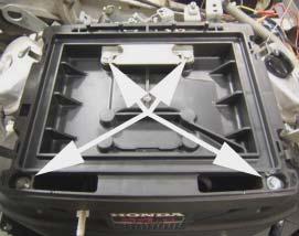
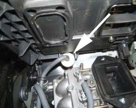
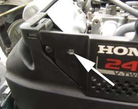
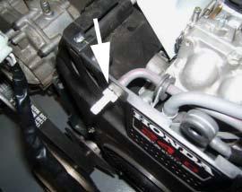
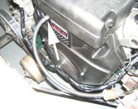
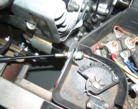
1 ENG JL CC1 ENGINE KIT INSTALLATION INSTRUCTIONS 24 HP Honda Engine Installation Kit For Gas Powered Club Car Models Thank you for purchasing the this quality product from Buggies Unlimited. The engine conversion kit you have purchased is designed to assist you in removing your existing engine package and to replace it with your 24 HP GX-670 TDW, V-Twin Honda engine. THIS KIT DOES NOT CONTAIN THE HONDA ENGINE, but it does include the components and instructions to aid in the process of engine replacement. Due to the size of this project, some steps may be abbreviated and may not be explained in full detail. In depth mechanical knowledge and experienced is assumed. Please read and understand these instructions carefully before starting this project. The additional time required will help you to understand the scope of the job ahead. CAUTION: Always disconnect the negative (-) cable from the batteries before beginning. Always support your cart on Jack Stands rather than a floor jack Always wear eye protection when working on your vehicle. Always clean up gasoline spills immediately and properly dispose of gasoline soaked rags TOOLS Note: Because of the extensive list of tools required for this kit installation, refer to the steps below to determine what tools will be required. INSTALLATION INSTRUCTIONS Rear Body Removal 1. Remove the 1/2 bolts at the bases of the roof struts. (See Figure 1 & 2). a. Lift the top and strut assembly off of the car and set aside. b. Remove the bottom seat cushion. 2. Remove the ½ bolts holding the seat back and sweater basket struts to the body. (See Figure 3 & 4). 3. Lift the seat back / sweater basket / bag rack assembly off the car and set aside. Figure 1 Figure 2 Note: For cars with rear seats or cargo boxes follow their reverse installation procedure to remove those accessories. 4. Remove the small screw holding the shift lever to the linkage and remove lever. Remove the four Phillips head screws holding the shift linkage to the body. Slide the shift linkage out of the body and set aside. Remove the two Phillips head screws holding the front of the body to the frame. (See Figure 5). 5. Remove the two black plastic scuff pads in the floor of the bag well. Remove the two exposed body bolts on the floor of the bag well. (See Figure 6). 6. Loosen the hose clamp connecting the engine intake hose to the air cleaner box and disconnect the hose. (See Figure 7). 7. Disconnect the rubber tie down strap holding the air cleaner box and remove the box / choke chamber from the car. 8. Lift the rear body off of the frame and set aside. Engine Removal 1. Disconnect the battery cables. 2. Disconnect the crankcase ventilation hose. (See Figure 8). 3. Disconnect the fuel line at the filter and plug line to prevent a fuel spill. (See Figure 9). 4. Disconnect the clear carburetor vent line and remove. (See Figure 10). 5. Disconnect the engine ground wire from the engine. (See Figure 11). 6. Disconnect the starter / generator ground wire from the frame. Disconnect the starter / generator power and activation wires. (See Figure 12) C/2S Disconnect the yellow oil light switch wire. (See Figure 13). Using clutch puller (Part Number TLSCC25707), remove the drive clutch, drive belt and Figure 3 Figure 4 Figure 5 Pg

 b. 2. Slide outer hub onto shaft with threaded hole facing out. (See Figure 33) c. Slide inner hub onto shaft, over key, and tighten set screw.")
. Then follow the pulley manufacturer s instructions (in the pulley box) to torque these three bolts. Should You Need To Remove The Pulleys a. Remove bolts from outer hub. b. Thread the bolts into the threaded holes on the inner hub c.")

.")

2 Jack Shaft & Drive Belt Installation 1. Insert the Jackshaft through the bearings in the Engine Mount. The shaft is installed from passenger side of the car to driver side. (See Figure 30). 2. Drive shaft through bearings until the tapered clutch end rests against the bearing face. 3. On the driver s side of the car, slide the Jackshaft Collar over the Jackshaft and seat it against the bearing face. (See Figure 31). 4. Install the Jackshaft pulley inner and outer hubs. a. 1. Insert Key into keyway. (See Figure 32) b. 2. Slide outer hub onto shaft with threaded hole facing out. (See Figure 33) c. Slide inner hub onto shaft, over key, and tighten set screw. (See Figure 34) d. Align the non threaded holes on the inner hub with the threaded holes on the outer hub. Thread the supplied black fasteners into the outer hub until they are hand tight. (See Figure 35). Then follow the pulley manufacturer s instructions (in the pulley box) to torque these three bolts. Should You Need To Remove The Pulleys a. Remove bolts from outer hub. b. Thread the bolts into the threaded holes on the inner hub c. Tighten the bolts into the outer face of the inner hub in an alternating pattern to push the two hubs apart. d. Loosen the set screw and remove the hub and pulley. Figure 12 Figure 13 Note: Be sure to tighten all three hub mounting bolts together in an alternating fashion. This ensures the hubs are seated evenly. Failure to do so can cause the mounting bolts to break when attempting to remove hubs. Also be careful not to over tighten hub mounting bolts as this may cause the bolts to break upon removal as well. 5. Install Crankshaft Pulley inner and outer hubs and ensure they are aligned with the jackshaft pulley. (See Figure 36). Figure 14 Note: In order to get the Crankshaft Pulley hubs to clear the frame, it may be necessary to unbolt the Engine Drop Bracket from the front of the engine tray, remove it, and lower the engine slightly. 6. Place a 5/16 X 18 X 1 bolt through the now unused bolt hole on the driver s side of the engine tray. Install the Tensioner Assembly over this bolt and lightly fasten with a 5/16 X 18 locknut. (See Figure 37) 7. Install the Drive Belt over both the Crankshaft and Jackshaft pulleys and around the Idler Pulley. 8. Press down on the Tensioner Arm to tighten the belt and secure the Tensioner with a 5/16 X 18 X 1 bolt, washer, and lock nut. (See Figure 38) 9. Completely tighten both Tensioner Arm bolts. 10. Check that the Drive Belt is properly centered on all three pulleys. If not remove tension from the belt and loosen either the Crankshaft or Jackshaft pulleys. Adjust as necessary. 11. Install the OEM drive clutch onto the passenger s side of the Jackshaft. Install the OEM drive belt onto the driven and drive clutches. (See Figure 39) Note: If the belt does not fi t properly, loosen the four bolts securing the engine assembly to the engine tray, slide the assembly to the desired position, and torque the engine mounting bolts. Figure 15 Figure 16 Note: Check to ensure that the driver s side brake cable will not rub against the Crankshaft Pulley. To provide adequate clearance, it may be necessary to remove the wire bracket holding the cable to the frame. Also check that the cable is properly secured with e-clips at the rear drums and under the frame near the brake linkage. If the cable is not properly connected it will fl ex under braking and may rub on the Crankshaft Pulley. Installing the Wiring Harness Figure 17 Pg
 3. Unbolt the 10 mm bolt on the engine case.")
 5. Set the white wire aside. 6.")


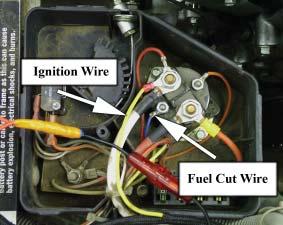
3 1. Using a ¼ bit, drill two holes and mount the alternator regulator as shown using the supplied 1/4 X 20 X 1 1/4 bolts and locknuts. (See Figure 40) 2. Plug in the regulator wire harness. Run the harness around the side of the engine above the drive clutch. (See Figure 41) 3. Unbolt the 10 mm bolt on the engine case. Attach the ring terminal for the alternator regulator and the ring terminal for the engine ground strap to this bolt and reinstall as shown. (See Figure 42) 4. Connect the two gray wires from the alternator harness to the two gray alternator output wires located beneath the starter. (See Figure 43) 5. Set the white wire aside. 6. Install the blue fuel cut solenoid wire to the small post on the ignition solenoid as shown. (This post will have the blue key switch wire already connected to it) (See Figure 44) 7. Run the wire out of the solenoid box, around to the engine, and connect it to the black and yellow wire coming out from under the air cleaner box on the Honda engine. Note: The fuel cut solenoid will be activated when the key is in the on position. As such, leaving the vehicle with the key turned on and the engine off for extended periods of time will drain the battery. 8. Relocate the factory wire harness around the solenoid box to the front of the engine compartment as shown. (See Figure 45) 6. Connect to white and red factory ignition kill wire to the black and red ignition kill wire coming out from behind the fan shroud on the Honda Engine. 7. The yellow oil pressure wire and pink starter/generator activation wire will no longer be used and should be secure out of the way. 8. Cut the ring terminal off the end of the 6 ga. white starter cable. 9. Strip the end of the starter cable and crimp or solder the supplied ring terminal to the cable. 10. Secure the starter cable to the positive post on the starter using a 12 mm wrench. (See Figure 46) 11. Remove the 5 amp ignition fuse from the solenoid box and replace with the supplied 30 amp fuse. 12. Cut away the rubber mat to install the floor mounted starter switch as shown. (See Figure 47) 13. Install the supplied Ignition Harness by running the wires as follows: a. The two red wires with small ring ends are run inside the frame I-Beams along with the OEM harness to the floor switch. (See Figure 48) b. The ring end on the yellow wire is connected to large post of the ignition solenoid on top of the white starter cable. (See Figure 44) c. The ring end on the red wire (with fuse holder) is connected to battery positive. (See Figure 49) d. The butt terminal on the red battery positive wire is connected to the white wire coming from the alternator harness. e. The red wire with the female spade connector is attached to the starter solenoid. (See Figure 46) f. The relay connector on the end of the harness is run along the body support of the frame and secured to the frame with #10 hardware as shown. (See Figure 50) g. Connect the black ground wire to the frame using the relay connector mounting hardware. (See Figure 51) 14. Plug the supplied relay into the relay connector. Figure 18 Figure 19 Figure 20 Figure 21 Figure 22 Note: When mounting the relay connector, make sure that it is not mounted too closely to the exhaust. Excessive heat can melt the plastic relay casing. Installing the Fuel Line 1. Remove the air cleaner box lid on top of the Honda engine. 2. Remove the air cleaner 3. Remove the two 10 mm and two 8 mm bolts that hold the air cleaner box to the engine. (See Figure 52) Figure With the air cleaner box off, remove the fuel line from the end of the fuel filter. (See Pg

 9.")


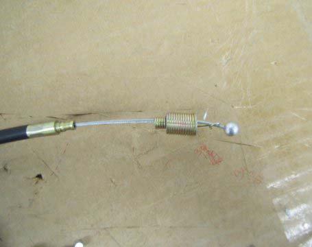
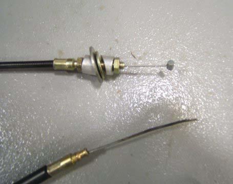
4 Figure 53) 5. Using a 3/16 bit, drill a hole through the plastic carburetor cover as shown. (See Figure 54) 6. Insert the Fuel Line Adaptor though this hole so that the small end faces the engine and tabs press against the outside of the plastic cover. Connect the fuel line to the 3/16 Adaptor barb and secure with existing hose clamp. (See Figure 55) 7. Reinstall the air cleaner and box. 8. Using the supplied fuel hose, run a new line from the stock filter to the 1/4 barb on the Fuel Line Adaptor. You may need to cut this hose to length. (See Figure 56) 9. Route the line away from the drive clutch. Throttle Cable Installation 1. Clip the metal ball from the end of the throttle cable and remove the spring. (See Figure 57) 2. Pull the inner wire cable out of the plastic cable sleeve. 3. Remove both jam nuts. 4. Install the Throttle Cable Spacers Reinstall the jam nuts on the outside of the spacers. Reinsert the inner wire cable into the plastic sleeve. (See Figure 58) 5. Using a high powered soldering gun or torch, apply silver solder to the cut end of the throttle cable to seal the cut and prevent fraying. 6. Reinstall the throttle cable onto the throttle rotor Reinstall the throttle rotor onto the pedal linkage. Reinstall the throttle cable onto the solenoid box as shown. (See Figure 59) 7. By rotating the Throttle Cable Spacers around, angle the cable so that is does not contact the Honda Engine. 8. Tighten both 10 mm jam nuts to hold the cable in place. 9. Install the solenoid box cover. 10. Loop the throttle cable over the engine and run it through the retaining clamp on the Honda engine throttle linkage. The throttle linkage is the arm on the side of the engine closest to the exhaust ports. Thread the soldered end of the throttle cable through the gold retainer on the linkage and tighten the set screws to secure the cable. (See Figure 60) 11. Check cable operation by depressing the accelerator and watching the throttle linkage on the engine. Exhaust Installation 1. Install the header pipe onto the exhaust ports of the Honda engine using the gaskets and lock nuts supplied with the engine. (See Figure 61) 2. Install the Engine Tray Support Bracket and Muffler Bracket using a 5/16 X 18 X 1 1/4 bolt and the existing hole in the engine tray. (See Figure 62) 3. Mark where the hole will need to be drilled in the engine tray to mount the lower end of the Engine Tray Support Bracket. (See Figure 63) 4. Drill hole using a 3/8 drill bit. 5. Using a 5/16 X 18 X 1 bolt and lock nut secure the lower end of the Engine Tray Support Bracket. 6. Install the Muffler onto the end of the header pipe and loosely fasten to the Muffler Bracket with the supplied 14 mm bolts. (See Figure 64) 7. Align the Muffler and mark where you will drill the hole for the other Muffler Bracket bolt. (See Figure 65) 8. Remove the Muffler and rotate the Muffler Bracket out of the way. 9. Using a 3/8 bit, drill the hole. 10. Swing the Muffler bracket into position and secure it with a 5/16 X 18 X 1 bolt and lock nut and tighten. 11. Tighten the engine tray to transmission mounting bolt. 12. Tighten the lower Engine Tray Support Bracket bolt. 13. Reinstall the Muffler onto the header pipe with the supplied muffler clamp. 14. Tighten the four muffler mounting bolts. 15. Tighten the muffler to header pipe clamp. 16. Thread the 1 X 5/16 X 18 bolt into the Exhaust Turn Down. 17. Slide the Exhaust Turn Down over the muffler exit 18. Tighten the Exhaust Turn Down set screw to secure it to the muffler. (See Figure 66) Figure 24 Figure 25 Figure 26 Figure 27 Figure 28 Figure 29 Pg
. 12. Disconnect the white and red ignition kill wire. (See Figure 17). 13.")
. 15. Remove solenoid box cover by removing the single retaining screw in the top. 16.")
. 17. Loosen the ¾ jam nuts holding the shifter cable to the transaxle.")


5 starter / generator belt. (See Figure 14). 10. Remove three 7/16 bolts holding the starter / generator pulley to the back of the clutch and remove the pulley. (See Figure 15). 11. Remove the brackets holding the ignition kill wire and throttle cable. (See Figure 16). 12. Disconnect the white and red ignition kill wire. (See Figure 17). 13. Pull the entire wiring harness away from the engine and set aside. 14. Disconnect the throttle cable from the governor linkage by removing the e-clip holding the throttle cable to the mount bracket. Remove throttle cable and remove throttle cable bracket from transaxle. (See Figure 18). 15. Remove solenoid box cover by removing the single retaining screw in the top. 16. Loosen both 10 mm jam nuts holding the throttle cable to the solenoid box. Remove the C-clip holding the plastic throttle rotor to the pedal linkage. Remove the rotor, disconnect, and remove the throttle cable and set everything aside. (See Figure 19). 17. Loosen the ¾ jam nuts holding the shifter cable to the transaxle. Disconnect the shifter cable from the transmission and set aside. Loosen the clamp holding the governor linkage on the transaxle. (See Figure 20). 18. Remove the governor linkage from the transaxle, remove the governor cable mount bracket, and set aside. 19. Support the engine tray with a jack. 20. Remove the six 14 mm engine to transmission nuts and bolts. (See Figure 21). 21. Remove the two ½ bolts holding the snubber to the engine tray and set the snubber aside. (See Figure 22). 22. Carefully lower the engine down and away from the transmission to slide it free from the mounting studs. Figure 6 Figure 7 CAUTION: Use caution when removing the engine from the car, it is recommended to have two or more people for this step to prevent dropping and damaging the engine, personal injury, or both. 24. With the engine and mount tray out of the car, remove the 14 mm nuts and 13 mm bolts holding the engine to the tray and set the engine aside. Remove the ½ bolts connecting the support brackets to the engine tray and discard these brackets. (See Figure 23). Figure 8 Preparation and Honda Engine installation 1. Cut approximately 3 from each side of the engine tray as shown. (See Figure 24). 2. Reuse the four 13 mm engine mount bolts to secure the Honda V-Twin to the Engine Mount supplied in the kit. (See Figure 25). Note: The exhaust ports of the Honda engine face the side of the Engine Mount with the angular relief cut. Figure 9 3. Install the two lower engine tray to transmission mounting bolts (See Figure 26). 4. Bolt the Honda V-Twin / Engine Mount assembly to the modified engine tray using the four supplied 8 MM bolts and fender washers Lift the car and support with jack stands. Raise the engine assembly into position from under the car. CAUTION: The Honda engine assembly is more than twice as heavy as the stock assembly. Use caution when lifting the engine into the car, it is STRONGLY recommended to have two or more people for this step to prevent dropping and damaging the engine, personal injury, or both. Figure Secure the engine assembly to the transmission with remaining engine to transmission mounting bolts and nuts. (See Figure 27). 8. Bolt the snubber to the Engine Drop Bracket with the existing snubber bolts. (See Figure 28). 9. Secure the Engine Drop Bracket to the front of the engine tray using the provided 5/16 X 18 X 1 ½ bolts. (See Figure 29). 10. If the snubber does not rest securely in the frame, loosen the axle u-bolts to allow the Figure 11 entire drive train assembly to rotate slightly until the snubber is properly seated. Pg
 Choke Cable Installation 1. Take out the three 1/4 screws to remove the choke button from the rear car body. 2.")
 6.")


6 CAUTION: Do not over tighten the set screw as you can strip the threads on the turn down. If you do destroy the threads, simply drill and tap another hole for the set screw. 19. Instal heat shield to muffler. (See figure 67) Choke Cable Installation 1. Take out the three 1/4 screws to remove the choke button from the rear car body. 2. Install the Choke Cable Plate onto the body with the supplied #10 hardware. (See Figure 68) 3. Reinstall the rear body onto the car. Installation is the reverse of steps on page Slide the Choke Cable through the opening in the Choke Cable Plate until the back of the pull lever rests against the plate. 5. Secure to the plate with the supplied 9/16 X 18 nut. (See Figure 69) 6. Route the Choke Cable over the exhaust through the retaining clamp and connect it to the choke linkage on the Honda engine. (See Figure 70) 7. Tighten both linkage set screws and verify Choke Cable operation. Engine Startup 1. Check the engine compartment to verify that no wires or cable are contacting the exhaust or any moving parts. Secure any loosing wiring, cables, or hoses with clamps. 2. Fill the engine with oil. 3. Verify that the OEM spark plugs have been replaced with NGK BPR2ES plugs. Figure 30 Figure 31 Note: If the factory installed spark plugs are not NGK s they will need to be replaced per the Honda Technical Service Bulletin. The OEM plug will foul quickly and cause extremely poor engine performance. 4. Reconnect the battery. 5. Use a jack to lift the rear wheels off the ground. 6. Put the car into gear and turn the key switch to the on position. 7. Verify that the fuel cut solenoid under the air cleaner box clicks. 8. Depress the Ignition Floor Switch and verify that the Ignition Harness relay clicks. 9. Double-check throttle and choke linkages for proper movement. 10. In order to engage the starter, the Ignition Floor Switch must be held down as the accelerator is depressed. Have an assistant nearby as it may be difficult to pull the Choke Cable, while holding the Ignition Floor Switch, and pressing on the accelerator. 11. Verify that the Honda engine will turn over and start. 12. Once the engine has started, release the Ignition Floor Switch. While the engine is running, ignition is completely controlled by the accelerator pedal. Figure 32 Figure 33 Note: If the engine will not start, double check all electrical connections and make sure that a gear has been selected. If the engine will crank but not start, make sure the choke and throttle linkages are connected properly and that the engine is getting fuel. 13. Finish reinstalling the remainder of the body, seat, and top components. 14. Test-drive the vehicle, checking for leaks and smooth operation. Note: If the engine will start and run fi ne under no load, but will buck and stumble while driving, make sure the spark plugs have been replaced. Figure 34 Note: If the take off speed is very abrupt or the engine will not rev to maximum RPM, check the adjustment of the throttle cable at the linkage. Adjustment of the throttle stop screw and position of the cable will fi ne tune the throttle response characteristics of the engine. Extra Throttle Adjustment You will notice that the factory DS throttle linkage does not provide enough throw to operate the Honda throttle from 0-100%. By connecting the cable in the OEM position on the Honda engine, you must either tune for low end drivability or top end throttle. Figure 35 Pg


. This will protect your clutch from impacts.")

7 However, by relocating the throttle cable connector further towards the center of the Honda throttle rotor it is possible to adapt the DS linkage to provide 0-100% throttle on the Honda engine. The DS throttle cable moves ¾ from 0-100% throttle. You will need to find the spot on the Honda throttle rotor that is displaced ¾ when the Honda engine is moved from 0-100% throttle. That spot is ¾ from the Honda throttle rotor pivot and is shown in Figure 71. Mark this spot and drill a 17/64 hole. Remove the e-clip off of the gold throttle cable connector and remove the connector from the throttle rotor. Reinstall the connector into the new hole and secure with the e-clip. You will now be able to enjoy full throttle control of the Honda engine with your OEM Club Car throttle linkage. DISCLAIMER: Due to the physical requirements of mechanically reversing the engine rotation, the OEM drive clutch has been relocated. The new placement puts the bottom third of the clutch below the engine tray and exposes the clutch to potential road hazards. As a result you will need to be aware that carelessly traversing rough or rocky terrain can result in damage to your clutch. For general on road use and light to moderate off road use the position of the clutch will not cause problems. If you anticipate severe off road use we strongly recommend you install a Buggies Unlimited Accessory Clutch Shield (call for information). This will protect your clutch from impacts. However, Buggies Unlimited is not responsible should you damage your clutch from negligent or reckless driving. Please pay attention while driving to prevent damage to critical drive train components. Please enjoy your new high power car and drive safely & responsibly. Ensure that all suspension and steering components are healthy and tight, double check the car alignment, check the condition and adjustment of the brakes, etc. It is important for your safety and the safety of others that your car is in good mechanical condition and well maintained when traveling at very high speeds. INDEMNIFICATION AND INSURANCE AGREEMENT 24 HP Honda Engine installation should be performed by a professional. The engine replacement kit purchaser assumes sole and entire responsibility for, and shall indemnify and save harmless Mattison Avenue Corporation (d.b.a. Buggies Unlimited), from any and all claim, liability, responsibility, and damage, or any costs or expenses resulting from any loss of life or injuries or claimed injuries to persons or property that may be sustained in connection with the use of any product before or after purchase, including but not limited to high speed motors. The high speed motor purchaser also shall indemnify Mattison Avenue Corporation (d.b.a. Buggies Unlimited) and save Mattison Avenue Corporation (d.b.a. Buggies Unlimited) harmless with respect to any and all liability that may be incurred. Golf carts are recommended for use only by those aged 16 and older. Golf carts can be especially hazardous to operate. Always remember that riding and alcohol/drugs don t mix. Never ride on public roads. Never carry more than two passengers (except shuttles and trams). Never engage in stunt driving. Avoid excessive speeds and be particularly careful on difficult terrain. Buggies Unlimited reserves the right, at any time, to discontinue or change specifications, prices, designs, features, models or equipment without notice and without incurring any obligation. Figure 36 Figure 37 Figure 38 Figure 39 Figure 40 Figure 41 Pg


8 Figure 42 Figure 43 Figure 44 Figure 45 Figure 46 Figure 47 Figure 48 Figure 49 Figure 50 Figure 51 Figure 52 Figure 53 Figure 54 Figure 55 Figure 56 Figure 57 Figure 58 Figure 59 Pg


9 Figure 60 Figure 61 Figure 62 Figure 63 Figure 64 Figure 65 Figure 66 Figure 67 Figure 68 Figure 69 Figure 70 Figure 71 Buggies Unlimited Copyright Buggies Unlimited. All Rights Reserved. Pg
10 Pg 10
BRK JL CC5 K Hydraulic Front Brake Kit For Club Car DS Model Installation Instructions
 BRK JL CC5 K Hydraulic Front Brake Kit For Club Car 1982-2005 DS Model Installation Instructions Kit Components: A) Master Cylinder Mounting Bracket (x1) B) Master Cylinder Assembly (x1) C) Brake Line
SK1001 SPEED KIT For 48-volt Club Car DS Model Installation Instructions
 SK00 SPEED KIT For 48-volt Club Car 995-005 DS Model Installation Instructions SK00 Club Car DS Speed Kit Installation Instructions Thank you for purchasing our exclusive SK00 Speed Kit. We take great
Safety - Installation and Operation:
 4x4 or 4x2 Instructions EZGO Electric Cars Thank you for purchasing your 4x4 or 4x2 conversion kit. Safety at all times whether during installation or operation is utmost importance. Before After!!!!!!!!!!!!!!
Jakes Big Block Conversion Kit (P/N 7216)
") Jakes Big Block Conversion Kit (P/N 7216) Before beginning be sure to read and understand the instructions. This kit is designed to give you maximum torque for those extreme off-road conditions. We thank
Jakes Big Block Conversion Kit (P/N 7216) Before beginning be sure to read and understand the instructions. This kit is designed to give you maximum torque for those extreme off-road conditions. We thank
1996+ Yamaha G16 / G22 Yamaha G29/YDRA Drive
 Vegas Carts & Performance 2995 Coleman St North Las Vegas, NV 89032 702-530-7753 VegasCarts.com 625cc Big Block Installation Instructions 1996+ Yamaha G16 / G22 Yamaha G29/YDRA Drive Revised 8/6/2018 1
»Product» Safety Warning
 #J9320, J9321 Installation Instructions 1986-1995 Jeep YJ 3" Body Lift Kit Read and understand all instructions and warnings prior to installation of product and operation of vehicle. Zone Offroad Products
625cc Big Block Installation Instructions Club Car DS / Carryall
 Vegas Carts & Performance 2995 Coleman St North Las Vegas, NV 89032 702-530-7753 VegasCarts.com 625cc Big Block Installation Instructions 1984-1996 Club Car DS / Carryall (DOES NOT FIT INGERSOLL RAND BOBCAT)
90 Utility Model Number A2013KUB2BUSZ SHARE OUR PASSION.
 2013 90 Utility Model Number A2013KUB2BUSZ TM SHARE OUR PASSION. TABLE OF CONTENTS 2013 ATV 90 (Model No. A2013KUB2BUSZ) BODY PANEL AND HEADLIGHT ASSEMBLY... 1 FRONT AND REAR RACK ASSEMBLY... 2 FRAME AND
INSTALLATION & OWNER S MANUAL
 1 of 18 INSTALLATION & OWNER S MANUAL (*Not including cab & other accessories) A/C Alternator Kit: Yamaha Drive & Drive2 P/N: 1ACYDR2DRK Recommended it be installed with Curtis Cab: Sandstone (p/n 1GCYD1-A,
***THE OWNER'S MANUAL MUST BE GIVEN TO THE END USE CUSTOMER AFTER COMPLETING THE INSTALLATION.***
 INSTALLATION INSTRUCTIONS FOR THE MOTOR TRIKE HARLEY MECHANICAL REVERSE 1999-2006 FIVE SPEED FLH LAST UPDATED: OCTOBER 2011 AS THE INSTALLER OF THIS MECHANICAL REVERSE, YOU MUST BECOME FAMILIAR WITH PROPER
LGT-306L / LB Club Car Precedent LED Light Bar Bumper Kit Installation Instructions
 LGT-306L / LB Club Car Precedent LED Light Bar Bumper Kit Installation Instructions Caution: Please read through the instructions carefully. Before starting this project, remove the system s positive and
C40008 & C40009 EXHAUST BRAKES
 EXHAUST BRAKES C40008 & C40009 1995 2003 Ford F250 / F350 7.3 L Powerstroke Diesel with manual transmissions 1995 1998 Ford F250 / F350 7.3 L Powerstroke Diesel with automatic transmission* *Requires the
Remove Air Cleaner Cover and. Filter
 Remove Air Cleaner Cover and Inspect paper filter for tears Foam pre-cleaner is washable if equipped Replace if necessary Filter Remove Trim Panel Pull throttle lever knob off Remove 3, 8mm screws Remove
JEEP WRANGLER (TJ), UNLIMITED (TJL), RUBICON MODELS BODY LIFT KIT INSTALLATION INSTRUCTIONS KIT# KIT# 973
, UNLIMITED (TJL), RUBICON MODELS BODY LIFT KIT INSTALLATION INSTRUCTIONS KIT# KIT# 973") JEEP WRANGLER (TJ), UNLIMITED (TJL), RUBICON MODELS BODY LIFT KIT INSTALLATION INSTRUCTIONS 1997-2006 2 KIT# 972 3 KIT# 973 WARNING Installation of a Performance Automotive Group body lift will change
JEEP WRANGLER (TJ), UNLIMITED (TJL), RUBICON MODELS BODY LIFT KIT INSTALLATION INSTRUCTIONS 1997-2006 2 KIT# 972 3 KIT# 973 WARNING Installation of a Performance Automotive Group body lift will change
1996 Aerostar/Ranger/Explorer
 Page 1 of 11 Section 03-01B: Engine, 3.0L V-6 IN-VEHICLE SERVICE 1996 Aerostar and Ranger Vehicles Workshop Manual Water Pump SPECIAL SERVICE TOOL(S) REQUIRED Description Tool Number Fan Clutch Holding
Riding Mowers. Z44 and Z52 Accu-Z Razor (S/N and above) SM Service Manual Printed 9/24/09
 SM Service Manual Printed 9/24/09") Riding Mowers Z44 and Z52 Accu-Z Razor (S/N 472620 and above) 23802 357-044SM Service Manual 2006 Printed 9/24/09 Copyright 2006 All rights Reserved Land Pride provides this publication as is without warranty
Riding Mowers Z44 and Z52 Accu-Z Razor (S/N 472620 and above) 23802 357-044SM Service Manual 2006 Printed 9/24/09 Copyright 2006 All rights Reserved Land Pride provides this publication as is without warranty
1 M-3000-H4 F150 4X4 Lowering Kit
 READ INSTRUCTIONS COMPLETELY THROUGH BEFORE STARTING. IT IS RECOMMENDED THAT INSTALLATION BE DONE BY A QUALIFIED MECHANIC. REPLACE ALL STOCK PARTS THAT ARE DAMAGED OR WORN. ALWAYS WEAR EYE PROTECTION.
INSTALLATION INSTRUCTIONS 97 FORD EXPEDITION
 INSTALLATION INSTRUCTIONS 97 FORD EXPEDITION 1. Read the instructions completely and carefully before you begin. Check the kit for proper contents (refer to the part s list and the picture diagrams). Before
Page 1 of HP B&S Vanguard Engine
 1405 Page 1 of 41 14 HP B&S Vanguard Engine 1405 Page 2 of 41 14 HP B&S Vanguard Engine Ref # Part Number Qty S/P/F Description BS-28Q777-0647-E1 1 14 HP B&S Vanguard Engine 1 BS-496412 1 Cylinder Assembly
2015 Corvette Supercharger System Instructions
 2015 Corvette Supercharger System Instructions These instructions are meant to serve as a guide to the installation of the ECS 2015 Corvette Supercharging system. Please be sure to use all safety equipment
Procharger Stage II Intercooled Supercharger System (11-14 GT)
") Procharger Stage II Intercooled Supercharger System (11-14 GT) Installation Time: Approximately one day. Installed on 2012 Mustang GT 5.0/Manual Required Tools 3/8 Socket Set (Standard and Metric) 1/2
Procharger Stage II Intercooled Supercharger System (11-14 GT) Installation Time: Approximately one day. Installed on 2012 Mustang GT 5.0/Manual Required Tools 3/8 Socket Set (Standard and Metric) 1/2
X4 (GREEN) (A2000ATF2AUSG) Page 1 of 80 AIR INTAKE ASSEMBLY
 (A2000ATF2AUSG) Page 1 of 80 AIR INTAKE ASSEMBLY") 2000 300 2X4 (GREEN) (A2000ATF2AUSG) Page 1 of 80 AIR INTAKE ASSEMBLY 2000 300 2X4 (GREEN) (A2000ATF2AUSG) Page 2 of 80 AIR INTAKE ASSEMBLY Ref # Part Number Qty S/P/F Description 1 3570-001 1 /P Intake,
2000 300 2X4 (GREEN) (A2000ATF2AUSG) Page 1 of 80 AIR INTAKE ASSEMBLY 2000 300 2X4 (GREEN) (A2000ATF2AUSG) Page 2 of 80 AIR INTAKE ASSEMBLY Ref # Part Number Qty S/P/F Description 1 3570-001 1 /P Intake,
INSTALLATION INSTRUCTIONS FOR THE TOMAHAWK ELECTRIC REVERSE
 INSTALLATION INSTRUCTIONS FOR THE TOMAHAWK ELECTRIC REVERSE LAST UPDATED: April 2018 Thank you for choosing the Motor Trike Electric Reverse. We ask that you read the directions before you start and follow
Retriever 5800G/P/D. revised 2/01 Form Number
 Retriever 5800G/P/D PARTS LIST Advance MODELS 56482005, 56482010, 56482015 This parts list is for machines after serial number 221134 All models covered in this manual are OBSOLETE revised 2/01 Form Number
Disconnect the APP sensor harness connector. See Fig. 4. Remove the accelerator pedal mounting nuts. Remove the APP assembly.
 ENGINE CONTROLS - REMOVAL, OVERHAUL & INSTALLATION - 6.6L DIESEL... Page 1 of 41 FUEL SYSTEMS ACCELERATOR PEDAL POSITION SENSOR Removal & Installation Disconnect the APP sensor harness connector. See Fig.
DODGE DAKOTA 3 KIT INSTALLATION INSTRUCTIONS KIT# 60043
 DODGE DAKOTA 3 KIT INSTALLATION INSTRUCTIONS 2000-2002 KIT# 60043 Installation of a Performance Automotive Group body lift kit will change the vehicle s center of gravity and handling characteristics both
INSTALLATION INSTRUCTIONS DODGE DAKOTA 2 KIT # 682 (2WD), 692 (4WD) 3 KIT # 683 (2WD), 693 (4WD)
, 692 (4WD) 3 KIT # 683 (2WD), 693 (4WD)") INSTALLATION INSTRUCTIONS 1997-1999 DODGE DAKOTA 2 KIT # 682 (2WD), 692 (4WD) 3 KIT # 683 (2WD), 693 (4WD) Installation of a Performance Accessories body lift kit will change the vehicle s center of gravity
INSTALLATION INSTRUCTIONS 1997-1999 DODGE DAKOTA 2 KIT # 682 (2WD), 692 (4WD) 3 KIT # 683 (2WD), 693 (4WD) Installation of a Performance Accessories body lift kit will change the vehicle s center of gravity
SMF / DSF / DTF SMF / DSF / DTF 200
 2006 SMF / DSF / DTF 200 1 The drawings in this parts book have been scaled so that parts can be easily recognized. 1 CYLINDER ASSY 2 CYLINDER ASSY Ref # Part # Description 1 410 0001A CYLINDER HEAD COVER
TOYOTA FJ CRUISER 6 SUSPENSION KIT
 92177000 TOYOTA FJ CRUISER 6 SUSPENSION KIT Thank you for choosing Rough Country for your suspension needs. Rough Country recommends a certified technician installs this system. In addition to these instructions,
mi Model 108 Compact Tractor Parts Catalog
 mi Model 108 Compact Tractor Parts Catalog Catalog No. 1226 PRICE 75 CENTS CASE MODEL 108 COMPACT TRACTOR Parts Catalog No. 1226 Leitch 2500 9-72 "'^^^l" 1" ifif --C: ^1=5 t^dj d- CASE MODEL 108 COMPACT
REMOVAL & INSTALLATION
 REMOVAL & INSTALLATION NOTE: For reassembly reference, label all electrical connectors, vacuum hoses and fuel lines before removal. Also place mating marks on engine hood and other major assemblies before
Installation Instructions Part Number
 Installation Instructions Part Number 84152143 Thank you for choosing Chevrolet Performance as your high performance source. Chevrolet is committed to providing proven, innovative performance technology
STX-26 Stump Grinder
 Form No. 3365-311 Rev B STX-26 Stump Grinder Model No. 23210 Serial No. 310000001 and Up Model No. 23210G Serial No. 310000001 and Up Register at www.toro.com. Original Instructions (EN) *3365-311* B Ordering
400 4x4 Euro MODEL NUMBER A2008IDG4BEUR (RED) MODEL NUMBER A2008IDG4BEUG (GREEN) MODEL NUMBER A2008IDG4BEUZ (CAT GREEN) MORE TO GO ON.
 MODEL NUMBER A2008IDG4BEUG (GREEN) MODEL NUMBER A2008IDG4BEUZ (CAT GREEN) MORE TO GO ON.") 2008 400 4x4 Euro Illustrated Parts Manual MODEL NUMBER A2008IDG4BEUR (RED) MODEL NUMBER A2008IDG4BEUG (GREEN) MODEL NUMBER A2008IDG4BEUZ (CAT GREEN) MORE TO GO ON. TM TABLE OF CONTENTS 2008 ATV 400 4x4
2008 400 4x4 Euro Illustrated Parts Manual MODEL NUMBER A2008IDG4BEUR (RED) MODEL NUMBER A2008IDG4BEUG (GREEN) MODEL NUMBER A2008IDG4BEUZ (CAT GREEN) MORE TO GO ON. TM TABLE OF CONTENTS 2008 ATV 400 4x4
5 Large spring 1. Key Start Kit Workman MDX Utility Vehicle. Preparing the Machine. Loose Parts. No Parts Required. Procedure
 Key Start Kit Workman MDX Utility Vehicle Model No. 119-9534 Form No. 3366-100 Rev B Installation Instructions Note: Determine the left and right sides of the machine from the normal operating position.
Retro it Steering Column
 Retro it Steering Column INSTALLATION INSTRUCTIONS for 1970-74 Cuda/Challenger FOR PART NUMBER S: 1620810010, 1620810020, 1620810051, 1620820010, 1620820020, 1620820051 S I NCE 1986 Instruction # 8000000005
10th letter in VIN: J
 08 0th letter in VIN: J Headlight G Br Speedometer Headlight Light Switch B Br Ignition Switch R B Y/R Brake Light Switch B G/Y Starter Relay Fuse A + G Starter Motor Rear Brake Light G/Y Br G Speed Sensor
»Product» Safety Warning
 #C9315 Installation Instructions 2000-2005 Suburban/Tahoe/Yukon 1500 2/4wd 3" Body Lift Read and understand all instructions and warnings prior to installation of product and operation of vehicle. Zone
ATV 50 Y-6 YOUTH CAT GREEN (A2004ATA2BUSZ) Page 1 of 50 A-ARM, FLOOR PANEL, AND BUMPER ASSEMBLY
 Page 1 of 50 A-ARM, FLOOR PANEL, AND BUMPER ASSEMBLY") 2004 ATV 50 Y-6 YOUTH CAT GREEN (A2004ATA2BUSZ) Page 1 of 50 A-ARM, FLOOR PANEL, AND BUMPER ASSEMBLY 2004 ATV 50 Y-6 YOUTH CAT GREEN (A2004ATA2BUSZ) Page 2 of 50 A-ARM, FLOOR PANEL, AND BUMPER ASSEMBLY
2004 ATV 50 Y-6 YOUTH CAT GREEN (A2004ATA2BUSZ) Page 1 of 50 A-ARM, FLOOR PANEL, AND BUMPER ASSEMBLY 2004 ATV 50 Y-6 YOUTH CAT GREEN (A2004ATA2BUSZ) Page 2 of 50 A-ARM, FLOOR PANEL, AND BUMPER ASSEMBLY
400 2x4/4x4 EFT SHARE OUR PASSION ṬM
 SHARE OUR PASSION ṬM 400 2x4/4x4 EFT Model Number A2009IDG2BETR (Red - 2x4) Model Number A2009IDG2BETZ (Cat Green - 2x4) Model Number A2009IDG4BETR (Red - 4x4) Model Number A2009IDG4BETG (Green - 4x4)
99-04 GT. Hellion Power Systems Mustang GT Kit Instructions
 Hellion Power Systems 99-04 Mustang GT Kit Instructions Part 1 Hellion recommends that the front suspension system be installed either by trained professionals or by 5.Remove rack bolts K-Member Installation
FRONT RACK, BODY PANEL, AND HEADLIGHT ASSEMBLIES
 FRONT RACK, BODY PANEL, AND HEADLIGHT ASSEMBLIES 0747-506 1 2506-107 1 Rack, Front - Assembly (inc. 2) 2 0411-576 1 Decal, Warning - Load 3 0441-592 4 Bushing 4 8410-835 4 Screw, Cap 5 0423-669 4 Spacer
CHEVY / GMC BLAZER / YUKON SUBURBAN BODY LIFT INSTALLATION INSTRUCTIONS KIT # KIT #10023
 3651 N Highway 89 Chino Valley, AZ 86323 (928) 636-7080 CHEVY / GMC BLAZER / YUKON SUBURBAN BODY LIFT INSTALLATION INSTRUCTIONS 1992-1994 2 KIT #10022 1992-1994 3 KIT #10023 Before you install this kit,
18SP680Rev3 EPA04 MBE 4000 Car Hauler Low Pressure Fuel Lines
 8SP680Rev3 EPA04 MBE 4000 Car Hauler Low Pressure Fuel Lines KIT DESCRIPTION These service kits include all necessary parts to replace the low pressure fuel lines between the fuel filter housing and fuel
w w w. h d o n l i n e s h o p. d e CRUISE CONTROL KIT GENERAL INSTALLATION -J04064 REV Kit Number Models Additional Parts Required
 -J006 REV. 006-08- CRUISE CONTROL KIT GENERAL Kit Number 7796-07 Models For the most up-to-date model fitment information, please see the product label or www.harley-davidson.com. Additional Parts Required.
Installation Instructions
 BY Trike Conversion Kit KAWASAKI Vulcan 900 CLASSIC- CLASSIC LT AND CUSTOM MODELS 2006-CURRENT Installation Instructions Revised 1-2015 California Sidecar Parts & Technical Support 434.263.8866 2 Table
Special Note About The JDM High Performance Water Pump:
 Page 1 of 30 JDM Engineering, Inc. home Call Us! 732-780- 0770 back to Installation Instructions Electric Fan Upgrade Kit Electric Fan Wiring Diagram Thank you for your purchase of the JDM Engineering
ETON America PARTS CATALOG. Beamer PN-2
 ETON America PARTS CATALOG Beamer PN- Table of Contents Beamer PN- PrdImg: \\Nt4serv\EtonData Figure No. 0 03 04 05 06 07 08 09 0 3 4 5 6 7 8 9 0 3 4 9 Content Referance Cylinder, Crankshaft and Piston
BEFORE BEGINNING INSTALLATION
 COMPLETE CHASSIS FUEL LINE KITS For 1996-2000 Honda Civic Equipped with B-Series Engine INSTALLATION INSTRUCTIONS PLEASE study these instructions carefully before beginning this installation. Most installations
BLACKBIRD INSTALLATION SUPPLEMENT
 BLACKBIRD INSTALLATION SUPPLEMENT FOR 2008-105 FORD 6.4 LITER DIESEL F-SERIES VERSION 3/10 Parts Blackbird Wiring Manual Installation Supplement 6.4 liter Diesel Owner s Manual Includes Warrantee Registration
03-04 Mach 1. Hellion Power Systems Mach 1 Kit Instructions
 Hellion Power Systems 03-04 Mach 1 Kit Instructions Part 1 Hellion recommends that the front suspension system be installed either by trained professionals or by 5.Remove rack bolts K-Member Installation
250 2x x4. Illustrated Parts Manual
 250 2x4 250 4x4 Model Number A2005ATE2AUSR (2X4 - Red) Model Number A2005ATE2AUSG (2X4 - Green) Model Number A2005ATE4AUSR (4X4 - Red) Model Number A2005ATE4AUSG (4X4 - Green) Illustrated Parts Manual
STX-26 Stump Grinder
 Form No. 3383-656 Rev B STX-26 Stump Grinder Model No. 23208 Serial No. 314000001 and Up Model No. 23208G Serial No. 314000001 and Up Register at www.toro.com. Original Instructions (EN) *3383-656* B Ordering
*1557BAG12* 1557BAG F /5 /6 LIFT KIT G THANK YOU FOR CHOOSING ROUGH COUNTRY FOR YOUR SUSPENSION NEEDS.
 2015-18 F-150 4 /5 /6 LIFT KIT THANK YOU FOR CHOOSING ROUGH COUNTRY FOR YOUR SUSPENSION NEEDS. 92155700G *1557BAG12* 1557BAG12 Rough Country recommends a certified technician install this system. In addition
Hydrostatic Zero-Turn Commercial Riding Mower
 Hydrostatic Zero-Turn Commercial Riding Mower Professional Turf Equipment 0" Fabricated Deck ILLUSTRATED PARTS LIST TABLE OF CONTENTS Frame Assembly.................................. 3 0" Fabricated Cutter
07-11 GM 1500 Pickup, Avalanche, Yukon, Tahoe, Suburban Front 2.5 Kit
 92130500 07-11 GM 1500 Pickup, Avalanche, Yukon, Tahoe, Suburban Front 2.5 Kit Thank you for choosing Rough Country for all your suspension needs. Rough Country recommends a certified technician install
ENGINE 1. ydrax3. Ref No.
 A ENGINE JR-900-00-00 A ENGINE ASSEMBLY CYLINDER HEAD JT0--00-00 HEAD, CYLINDER JN--0-00..GUIDE, VALVE JT0--00-00 GASKET, CYLINDER HEAD 90-000-00 BOLT 900-00-00 WASHER, PLATE 990-0-00 PIN, DOWEL 9-0-00
Nissan Pathfinder (R50) Automatic to Manual Transmission Conversion Manual
 Automatic to Manual Transmission Conversion Manual") 1996 1999 Nissan Pathfinder (R50) Automatic to Manual Transmission Conversion Manual 1 1996 1999 Nissan Pathfinder (R50) Automatic to Manual Transmission Conversion Manual Conversion performed and Manual
1996 1999 Nissan Pathfinder (R50) Automatic to Manual Transmission Conversion Manual 1 1996 1999 Nissan Pathfinder (R50) Automatic to Manual Transmission Conversion Manual Conversion performed and Manual
05-07 F250 6 SUSPENSION KIT
 92159300 Stabilizer Drop Brackets Track Bar Bracket Control Arm Bracket Brake Line Drop Bracket Sway Bar Link Ext. Hardware Bags Pitman Arm 6111 Add-a-leaf 6578 3 Block and U-Bolt Kit 05-07 F250 6 SUSPENSION
2006 Honda Civic SI Supercharger Kit Installation Instruction Kit #
 2006 Honda Civic SI Supercharger Kit Installation Instruction Kit #350-091 3239 MONIER CIRCLE, STE.5 RANCHO CORDOVA, CA 95742 916.635.4550 FAX 916.635.4632 www.ct-engineering.com INS-157 VERSION: 3.25.2009
90 Y-12 Youth. Model Number A2005H4B2BUSR (Red) Model Number A2005H4B2BUSZ (Cat Green) Illustrated Parts Manual
 Model Number A2005H4B2BUSZ (Cat Green) Illustrated Parts Manual") 90 Y-12 Youth Model Number A2005H4B2BUSR (Red) Model Number A2005H4B2BUSZ (Cat Green) Illustrated Parts Manual 2005 TABLE OF CONTENTS 2005 ATV 90 Y-12 Youth Red (Model No. A2005H4B2BUSR) Cat Green (Model
90 Y-12 Youth Model Number A2005H4B2BUSR (Red) Model Number A2005H4B2BUSZ (Cat Green) Illustrated Parts Manual 2005 TABLE OF CONTENTS 2005 ATV 90 Y-12 Youth Red (Model No. A2005H4B2BUSR) Cat Green (Model
*1274BAG9* 1274BAG GM 4-6 SUSPENSION KIT N2.0. Thank you for choosing Rough Country for your suspension needs A
 92127400A 88-98 GM 4-6 SUSPENSION KIT N2.0 Thank you for choosing Rough Country for your suspension needs. *1274BAG9* 1274BAG9 Rough Country recommends a certified technician installs this system. In addition
71253, XL 440H Lawn Tractor, 2008 (SN ) : BLOWER HOUSING ASSEMBLY BRIGGS AND STRATTON MODEL 31P E1 [1/
 : BLOWER HOUSING ASSEMBLY BRIGGS AND STRATTON MODEL 31P E1 [1/") 71253, XL 440H Lawn Tractor, 2008 (SN 280000001-280999999) : BLOWER HOUSING ASSEMBLY BRIGGS AND STRATTON MODEL 31P777-0133-E1 [1/ Page 1 of 50 71253, XL 440H Lawn Tractor, 2008 (SN 280000001-280999999)
71253, XL 440H Lawn Tractor, 2008 (SN 280000001-280999999) : BLOWER HOUSING ASSEMBLY BRIGGS AND STRATTON MODEL 31P777-0133-E1 [1/ Page 1 of 50 71253, XL 440H Lawn Tractor, 2008 (SN 280000001-280999999)
FORD BRONCO BODY LIFT KIT INSTALLATION INSTRUCTIONS KIT # KIT #843
 FORD BRONCO BODY LIFT KIT INSTALLATION INSTRUCTIONS 1992-1996 2 KIT #842 1992-1996 3 KIT #843 This kit should only be installed on a vehicle that is in good working condition. Before you install the kit,
This suspension system was developed using a Maximum tire size of 33 X 12.5 with a 17 x 9 aftermarket wheel with 4 1/2-5 backspacing..
 92174700 Thank you for choosing Rough Country for your suspension needs. 2005-15 TACOMA 6 Kit Rough Country recommends a certified technician install this system. In addition to these instructions, professional
Illustrated Parts Manual. Model Number A2011ICS4BUSG (Green) A2011ICS4BOSG (Green - International)
 A2011ICS4BOSG (Green - International)") Illustrated Parts Manual 2 1 10 650 Model Number A2011ICS4BUSG (Green) A2011ICS4BOSG (Green - International) S H A R E O U R PAS S IO N. TM TABLE OF CONTENTS 2011 ATV 650 Green (Model No. A2011ICS4BUSG)
Illustrated Parts Manual 2 1 10 650 Model Number A2011ICS4BUSG (Green) A2011ICS4BOSG (Green - International) S H A R E O U R PAS S IO N. TM TABLE OF CONTENTS 2011 ATV 650 Green (Model No. A2011ICS4BUSG)
SAFETY THIS PRODUCT IS FOR OFFROAD USE ONLY. ALL LIABILITY FOR INSTALLATION AND USE RESTS WITH THE OWNER.
 SAFETY Your safety and the safety of others is very important. In order to help you make informed decisions about safety, we have provided installation instructions and other information. These instructions
CYLINDER. Ref. Part No. Number Description Qty Remarks
 A1 CYLINDER 1 J38-11102-00-00 CYLINDER HEAD ASSEMBLY. 1 2 J38-11133-09-00. GUIDE, INTAKE VALVE..... 2 3 99510-12016-00 PIN, DOWEL.............. 2 4 95811-08070-00 BOLT, FLANGE............ 3 5 95811-08045-00
Installation Manual TWM Performance Short Shift Kit Stage 1 and Stage 2 MazdaSpeed 6
 Page 1 Installation Manual TWM Performance Short Shift Kit Stage 1 and Stage 2 MazdaSpeed 6 Please Note: It is preferable to park on a flat surface, as you will have to engage and disengage the hand brake
Table Of Contents TABLE OF CONTENTS INTRODUCTION INSTALLATION OPERATING INSTRUCTIONS APPENDIX ABOUT THE JUICE... 3 SAFETY TERMS...3 INTRODUCTION...
 Ford Juice installation Instructions **read important safety information in this manual** TABLE OF CONTENTS F o r d J u i c e Table Of Contents ABOUT THE JUICE... 3 SAFETY TERMS...3 INTRODUCTION... 3 PRODUCT
Table of Contents. 4 Getting Started 4 About the Juice 5 Safety Terms 5 Product Registration 6 Important Notes 7 Truck Orientation
 Table of Contents 4 Getting Started 4 About the Juice 5 Safety Terms 5 Product Registration 6 Important Notes 7 Truck Orientation 8 Juice Installation 1999-2003 (7.3L) 8 Supplied Items & Required Tools
ATV 90 UTILITY GREEN (A2006KUB2BUSG) Page 1 of 60 AIR INTAKE ASSEMBLY
 Page 1 of 60 AIR INTAKE ASSEMBLY") 2006 ATV 90 UTILITY GREEN (A2006KUB2BUSG) Page 1 of 60 AIR INTAKE ASSEMBLY 2006 ATV 90 UTILITY GREEN (A2006KUB2BUSG) Page 2 of 60 AIR INTAKE ASSEMBLY Ref # Part Number Qty S/P/F Description 1 3303-005
2006 ATV 90 UTILITY GREEN (A2006KUB2BUSG) Page 1 of 60 AIR INTAKE ASSEMBLY 2006 ATV 90 UTILITY GREEN (A2006KUB2BUSG) Page 2 of 60 AIR INTAKE ASSEMBLY Ref # Part Number Qty S/P/F Description 1 3303-005
REAR ENGINE RIDER 42 MOWER SERIES 22
 Parts Manual for REAR ENGINE RIDER MOWER SERIES MODELS 1BVE CONTENTS DESCRIPTION PAGE(S) DESCRIPTION PAGE(S) WHEELS- TIRES... - FRONT END, STEERING.... - MAIN CASE... - DIFFERENTIAL, R. H. FENDER... 8-9
'99-03 CHEVROLET/GMC IFS 4WD 6" SUSPENSION SYSTEM P/N INSTALLATION INSTRUCTIONS
 1/16/04 '99-03 CHEVROLET/GMC IFS 4WD 6" SUSPENSION SYSTEM P/N. 10-41099 INSTALLATION INSTRUCTIONS NOTE: Each Lift Kit and options to Lift Kits are packaged separately. Therefore, installation procedures
cc Fun Kart. Illustrated Parts Manual RECOMMENDED MINIMUM OPERATOR AGE: 12
 Illustrated Parts Manual 6150 150cc Fun Kart RECOMMENDED MINIMUM OPERATOR AGE: 12 THIS VEHICLE IS FOR OFF-ROAD USE ONLY THIS VEHICLE IS NOT DESIGNED FOR USE ON RENTAL TRACKS OR RACING BEFORE OPERATING
ATV I l. l u. r a. Parts Manual ARCTIC CAT. 250 cc/300 cc
 2000 I l l u st ATV 250 cc/300 cc Model No. A2000ATE2AUSG (250 - Green) Model No. A2000ATE2AUSR (250 - Red) Model No. A2000ATF2AUSG (300 2x4 - Green) Model No. A2000ATF2AUSR (300 2x4 - Red) Model No. A2000ATF4AUSG
DVX 90 MODEL NUMBER A2008KSB2BUSD (BLACK-RED) MODEL NUMBER A2008KSB2BUSE (BLACK-CAT GREEN) MORE TO GO ON. TM
 MODEL NUMBER A2008KSB2BUSE (BLACK-CAT GREEN) MORE TO GO ON. TM") 2008 DVX 90 Illustrated Parts Manual MODEL NUMBER A2008KSB2BUSD (BLACK-RED) MODEL NUMBER A2008KSB2BUSE (BLACK-CAT GREEN) MORE TO GO ON. TM TABLE OF CONTENTS Black-Red (Model No. A2008KSB2BUSD) Black-Cat
2008 DVX 90 Illustrated Parts Manual MODEL NUMBER A2008KSB2BUSD (BLACK-RED) MODEL NUMBER A2008KSB2BUSE (BLACK-CAT GREEN) MORE TO GO ON. TM TABLE OF CONTENTS Black-Red (Model No. A2008KSB2BUSD) Black-Cat
»Product» Safety Warning
 #F2622 Installation Instructions 1997-2003 Ford F-150 4WD 6" Suspension System Read and understand all instructions and warnings prior to installation of product and operation of vehicle. Zone Offroad
LGT-312L E-Z-Go TXT Light Bar Bumper Kit Installation Instructions
 LGT-312L E-Z-Go TXT 2014+ Light Bar Bumper Kit Installation Instructions Caution: Please read through the instructions carefully. Before starting this project, remove the system s positive and negative
3651 N Highway 89 Chino Valley, AZ (928)
") 3651 N Highway 89 Chino Valley, AZ 86323 (928) 636-7080 CHEVY TRUCK 2 & 3 BODY LIFT KIT INSTALLATION INSTRUCTIONS 1973-1987 STEPSIDE PICKUP KIT# 512 (2 ), 513 (3 ) 1973-1987 FLEETSIDE PICKUP KIT# 522 (2
3651 N Highway 89 Chino Valley, AZ 86323 (928) 636-7080 CHEVY TRUCK 2 & 3 BODY LIFT KIT INSTALLATION INSTRUCTIONS 1973-1987 STEPSIDE PICKUP KIT# 512 (2 ), 513 (3 ) 1973-1987 FLEETSIDE PICKUP KIT# 522 (2
I. Before starting installation
 5. Park the vehicle on a clean, dry, flat, level surface and block the tires so the vehicle cannot roll in either direction. A. Disconnect battery cables 1. Disconnect the negative cable first, then the
PRODUCT USE INFORMATION
 9RC61000 Jeep YJ Body Lift Thank you for choosing Rough Country for all your suspension needs. This body lift fits both manual and Automatic equipped vehicles!!! Refer to last page of this Instruction
CYLINDER. Ref. Part No. Number Description Qty Remarks
 A1 CYLINDER 1 J38-11102-00-00 CYLINDER HEAD ASSEMBLY. 1 2 J38-11133-09-00. GUIDE, INTAKE VALVE..... 2 3 99510-12016-00 PIN, DOWEL.............. 2 4 95811-08070-00 BOLT, FLANGE............ 3 5 95811-08045-00
14A6816H190 GT-2150 (2003) Page 1 of 28 Carburetor
 Page 1 of 28 Carburetor") 14A6816H190 GT-2150 (2003) Page 1 of 28 Carburetor 14A6816H190 GT-2150 (2003) Page 2 of 28 Carburetor TC-640221 1 /P Carburetor (Incl 184 of Engine Parts Lists) 1 TC-640216 1 Throttle Shaft & Lever Assembly
14A6816H190 GT-2150 (2003) Page 1 of 28 Carburetor 14A6816H190 GT-2150 (2003) Page 2 of 28 Carburetor TC-640221 1 /P Carburetor (Incl 184 of Engine Parts Lists) 1 TC-640216 1 Throttle Shaft & Lever Assembly
Service Manual. Bolens 683 Series Box Frame Tractor IMPORTANT: READ SAFETY RULES AND INSTRUCTIONS CAREFULLY
 Service Manual Bolens 683 Series Box Frame Tractor IMPORTANT: READ SAFETY RULES AND INSTRUCTIONS CAREFULLY This Service Manual is not a substitute for the Operator s Manual. You must read, understand and
JEEP WRANGLER, RUBICON, UNLIMITED (TJ & TJL) 1 BODY LIFT KIT INSTALLATION INSTRUCTIONS KIT# 951
 1 BODY LIFT KIT INSTALLATION INSTRUCTIONS KIT# 951") 3651 N Highway 89 Chino Valley, AZ 86323 (928) 636-7080 www.p-a-g.net JEEP WRANGLER, RUBICON, UNLIMITED (TJ & TJL) 1 BODY LIFT KIT INSTALLATION INSTRUCTIONS 1997-2006 KIT# 951 Installation of a Performance
3651 N Highway 89 Chino Valley, AZ 86323 (928) 636-7080 www.p-a-g.net JEEP WRANGLER, RUBICON, UNLIMITED (TJ & TJL) 1 BODY LIFT KIT INSTALLATION INSTRUCTIONS 1997-2006 KIT# 951 Installation of a Performance
PRE-INSTALLATION. INSTALLATION INSTRUCTIONS Front Ford F150 4WD 4" Suspension Lift Kit
 2015 Ford F150 4WD 4" Suspension Lift Kit PRE-INSTALLATION 2 - Knuckle (Driv/Pass) 2 - Crossmember (Front/Rear) 2 - Differential Bracket (Driv/Pass) 1 - Diff. Brace Bracket (Pass) 2 - Front Brake Line
Read and understand all instructions and warnings prior to installation of product and operation of vehicle.
 #F9378 Installation Instructions 1998-2000 Ford Ranger 3" Body Lift Kit Read and understand all instructions and warnings prior to installation of product and operation of vehicle. Zone Offroad Products
LGT-311L Bumper LED Light Kit EZ-Go RXV Installation Instructions
 LGT-311L Bumper LED Light Kit EZ-Go RXV Installation Instructions Caution: Please read through the instructions carefully. Before starting this project, remove the system s positive and negative connections
KIT # MC-2911, MC-2923 FOR ALL YEAR SUZUKI M-109R SERIES
 Congratulations on your purchase of an Arnott Motorcycle Air Suspension system. This system provides you with the ability to maintain your bike at a constant level regardless of load, resulting in enhanced
S/N 1H019H - 1H310H Page 1 of 33 46" Cutting Deck Assembly
 1180 S/N 1H019H - 1H310H Page 1 of 33 46" Cutting Deck Assembly 1180 S/N 1H019H - 1H310H Page 2 of 33 46" Cutting Deck Assembly 1 17982 1 S Reinforcement Spindle Plate 2 618-0430 1 S Spindle Assembly w/
Tools Needed: Class 8.8 Class MM 55ft/lbs 75ft/lbs 14MM 85ft/lbs 120ft/lbs 16MM 130ft/lbs 165ft/lbs 18MM 170ft/lbs 240ft/lbs
 921788000 JEEP JK 6 LONGARM Rough Country recommends a certified technician install this system. In addition to these instructions, professional knowledge of disassemble/reassembly procedures as well as
DTR JL CC TRACTION CONTROL SYSTEM INSTALLATION INSTRUCTIONS - For
 DTR JL CC TRACTION CONTROL SYSTEM INSTALLATION INSTRUCTIONS - For 1986~2006 Gas or Electric Club Car Models with the Kawasaki Transaxle Assembly Thank you for purchasing this quality product from Buggies
HAMMERHEAD GT200. Page 1 of 9
 HAMMERHEAD GT200 Figue Part Number Description F1-1 M200-0101 CYLINDER HEAD SUBASSY F1-2 98056-57713-00 SPARK PLUG (C7HSA NGK) F1-3 M150-1001010 CYLINDER HEAD GASKET F1-4 M150-1001004 CARBURETOR INSULATOR
07-UP AVALANCHE 7.5 KIT
 92120900R1 07-UP AVALANCHE 7.5 KIT Thank you for choosing Rough Country for your suspension needs. We appreciate your business!! This kit will not fit vehicles equipped with electric steering or trucks
Trike Conversion Kit ROADLINER, STRATOLINER, & STRATOLINER DELUXE
 by Trike Conversion Kit ROADLINER, STRATOLINER, & STRATOLINER DELUXE Installation Instructions Revised 1-2015 California Sidecar Parts & Technical Support 434.263.8866 Table of Contents: 1. Warnings and
Dodge 5 Lift Kit Thank you for choosing Rough Country Suspension for your Off Road needs.
 *1368BAG4* 1368BAG4 921368200 2014-16 2500 Dodge 5 Lift Kit Thank you for choosing Rough Country Suspension for your Off Road needs. Rough Country recommends a certified technician installs this system.
07-11 GM 4WD 1500 P/U 1 1/4 Body Lift
 92RC70100 07-11 GM 4WD 1500 P/U 1 1/4 Body Lift Thank you for choosing Rough Country for all your suspension needs. Rough Country recommends a certified technician install this kit. Attempts to install
*1609BAG8* 1609BAG8 JEEP JK 3 1/2 SUSPENSION KIT A
 JEEP JK 3 1/2 SUSPENSION KIT 92160900A *1609BAG8* 1609BAG8 Thank you for choosing Rough Country for your suspension needs. Please read instructions before beginning installation. Check the kit hardware
AEV30308AA Last Updated: 05/31/18. 4 DUALSPORT sc SUSPENSION system for RAM 1500 air ride standard and rebel INSTALLATION GUIDE
 AEV30308AA Last Updated: 05/31/18 4 DUALSPORT sc SUSPENSION system for RAM 1500 air ride standard and rebel INSTALLATION GUIDE PLEASE READ BEFORE YOU START TO GUARANTEE A QUALITY INSTALLATION, WE RECOMMEND