DENISON HYDRAULICS. axial piston variable displacement with auxiliary package external replenishing pump Goldcup series P11S & P14S C mod
|
|
|
- Ashlee Montgomery
- 6 years ago
- Views:
Transcription


1 DENISON HYDRAULICS axial piston variable displacement with auxiliary package external replenishing pump Goldcup series P11S & P14S C mod service information Publ. S1-AM023-C Revised 6/04
2 CONTENTS PAGE seal kits typical characteristics fluid connections installation maintenance comparison of solid contamination classification systems start up procedures troubleshooting disassembly rework of wear part assembly drive shaft & bearing barrel & auxiliary drive shaft rocker cam assembly piston/shoe/retainer assembly mtg. flg./cradle/barrel/aux. shaft assy housing assembly hsg./end cap/cam/barrel assembly port block assembly port block/housing assembly gerotor & barrel holddown valve block assembly (after 7-93) valve block assembly for special mounting of servovalve (after 7-93) adapter assembly check valve assembly shuttle valve assembly pilot valve assembly shaft & seal installation A mod shaft seal replacement B mod shaft seal replacement counterbalance servo stem installation control cover installation instructions for replenishing isolation plug port locations gage pressure ranges conversion of A or B mod to C mod test procedure installation drawing hydraulic circuit pump key sheet conversion formulas SEAL KITS part no. pump seal kit complete, std. valve block, less control CW rotation S pump seal kit complete, std. valve block, less control CCW rotation S shaft seal - outer shaft seal - inner CW rotation shaft seal - inner CCW rotation std. valve block seal kit S hi IQ valve block seal kit S shuttle valve seal kit S ** thru 6**control S A control S ** control S **control S output indicator, 1** and 4A control S **4 torque limiter S Note: Throughout this bulletin, metric quantities are indicated in parenthesis, and decimal point is designated by a period 2
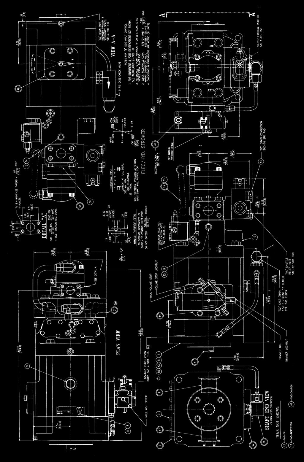
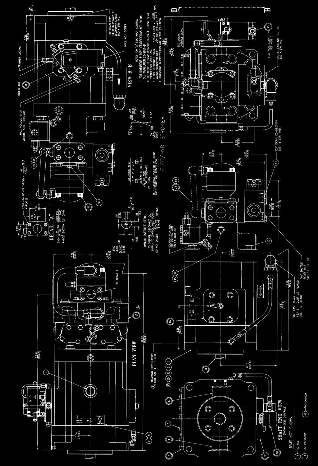
3 INSTALLATION TYPICAL CHARACTERISTICS Specification Term Goldcup 11 Goldcup 14 displacement at max. angle in 3 /rev cm 3 /rev. (180) (229) pressure continuous psi bar (345) (345) pressure intermittent psi bar (414) (414) speed, max. continuous-full stroke RPM speed, max. continuous-half stroke RPM flow, ports A or 1800 RPM GPM (theoretical) l/min. (324.4) (412.9) flow, int. aux RPM GPM (theoretical) l/min. (63.1) (63.1) flow, ext. aux RPM GPM (theoretical) l/min. (37.2) (37.2) replenish pressure psi minus case pressure bar (22,76-25,52) (22,76-25,52) servo pressure minus case psi zero discharge pressure bar ( ) ( ) max. continuous case pressure psi bar (5.2) (5.2) max. intermittent case pressure psi bar (8.6) (8.6) control on - stroke response time sec typ. compensator off - stroke time sec mounting-4 bolt flange SAE E E shaft-spline or keyed SAE E E weight w/spg. ctd. rotary servo lbs kg. (220) (220) FLUID CONNECTIONS J1 PORT LOCATIONS AND SIZES ports A& B (system) SAE code 62 split flange in. 1-1/2 mm (38.1) port AG, BG (A&B system gage) straight thread O-ring seal SAE -6 port C (aux. pump inlet) SAE code 61 split flange in. 1-1/4 mm (31.8) port D1 (aux.case drain) straight thread O-ring seal SAE -16 port D2 (case drain) 37 0 flared SAE -16 port D3 (repl relief drain) straight thread O-ring seal SAE -16 port DG (case gage) straight thread O-ring seal SAE -6 port DG2 (bearing flush) straight thread O-ring seal SAE -4 port DG3 (air bleed) straight thread O-ring seal SAE -4 port DS (shuttle repl pilot drain) straight thread O-ring seal SAE -4 port FA, FB (control pressures) straight thread O-ring seal SAE -6 port G (servo pressure both sides) st. thd. O ring seal SAE -4 port G2 (servo pressure A side) straight thread O-ring seal SAE -8 port I (external aux. pump inlet) SAE code 61 split flange in. 1-1/4 mm (38.1) port J (internal aux. pump outlet) SAE -8 port J1 (internal aux. pump outlet) SAE -10 port K (aux. repl. inlet) straight thread O-ring seal SAE -16 port KG (repl. gage) straight thread O-ring seal SAE -6 port SD (seal drain) straight thread O-ring seal SAE -4 port V (common vent) straight thread O-ring seal SAE -4 port VA, VB (A&B individual vents) straight thread O-ring seal SAE -4 3
4 INSTALLATION INTRODUCTION DESCRIPTION The DENISON HYDRAULICS Goldcup 11 and Goldcup 14 axial piston pumps feature advance design concepts which are time proven and provide for advance pumping and control concepts. The instructions contained in this manual cover complete disassembly and re-assembly of the unit. Before proceeding with the disassembly or re-assembly of any unit, this manual should be studied in order to become familiar with proper order and parts nomenclature. The use of a rocker cam to control the pump displacement provides a small package size, reduces wear, and speeds control response. The control vane actuator eliminates linkage and backlash inherent in typical stroking cylinder designs. Standard controls for the Goldcup units are rotary servo and compensator over-ride. Additional optional controls are also available. MOUNTING SHAFT INFORMATION This pump is designed to operate in any position The mounting hub and four bolt mounting flange are in full conformance with SAE standard. The pump shaft must be in alignment with the shaft of the driven load and should be checked with a dial indicator. The mounting pad or adapter into which the fluid pump pilots must be concentric with the pump shaft to prevent bearing failure. This concentricity is particularly important if the shaft is rigidly connected to the driven load without a flexible coupling. Splined: The shafts will accept a maximum misalignment of.006 TIR (0.15 mm). Angular misalignment at the male and female spline axes must be less than ±.002 per inch radius (0.002 mm per mm radius). The coupling interface must be lubricated. DENISON HYDRAULICS recommends lithium- molybdenum disulfide or similar grease. The female coupling should be hardened to Rc and must conform to SAE-J498B (1971) class 1 flat root side fit. Keyed: High strength heat treated keys must be used. Replacement keys must be hardened to Rc. The key corners must be chamfered ( mm) at 45 0 to clear radii that exist in the keyway. SIDE LOAD PIPING Keyed shafts will accept a side load of 1000 lb. (454 kg) at the center of the key, with a B10 life of hours at 1800 RPM and 40 psi case pressure. Do not use galvanized pipe. Galvanized coating can flake off with contin- CAUTION: ued use. Connect inlet and outlet lines to the port block of the pump. The maximum case pressure is 75 PSI (5.7 bar) continuous, 125 PSI (8.6 bar) intermittent. A 5 PSI (0.3 bar) case pressure check valve is included in the normal case drain port, D2, to be certain the case is filled with oil at all times. The case leakage line must be of sufficient size to prevent back pressure in excess of 75 PSI (5.7 bar) and returned to the reservoir below the surface of the oil as far from the supply suction as possible. All fluid lines, whether pipe, tubing, or hose must be adequate size and strength to assure free flow through the pump. An undersize inlet line will prevent the pump from operating at full rated speed. An undersize outlet line will create back pressure and cause heat generation. Flexible hose lines are recommended. If rigid piping is used, the workmanship must be accurate to eliminate strain on the pump port block or to the fluid connections. Sharp bends in the lines must be eliminated wherever possible. All system piping must be cleaned with solvent or equivalent before installing pump. Make sure the entire hydraulic system is free of dirt, lint, scale, or other foreign material. Flushing with a large temporary high pressure loop filter is recommended. SERVICE INFORMATION RECOMMENDED FLUIDS VISCOSITY These hydraulic products are designed to give long dependable service when properly applied and their systems properly maintained. These general instructions apply to typical systems. Specific instructions for particular equipment can be developed from them. The fluid recommended for use in these pumps and motors has a petroleum base and contains agents which provide oxidation inhibition and anti-rust, anti-foam and de-aerating properties as described in DENISON HYDRAULICS standard HF-1. Where antiwear additive fluids are specified, see DENISON HYDRAULICS standard HF-0. Max. at cold start SUS (1600 cst) (at low pressure, low flow, and if possible, low speed) Max. at full power SUS (160 cst) Optimum for max. life SUS (30 cst) Minimum at full power - 60 SUS (10 cst) 4
5 INSTALLATION VISCOSITY INDEX TEMPERATURE ALTERNATE FLUIDS 90 V.I. minimum. Higher values extend the range of operating temperature but may reduce the service life of the fluid. Determined by the viscosity characteristics of the fluid used. Because high temperatures degrade seals, reduce the service life of the fluid and create hazards, fluid temperatures should not exceed F (82 0 C) at the case drain. Some applications require fire-resistant fluids. They will give good service if the system is originally designed for their use. Permissible fire resistant fluids include: Type Water-in-oil invert emulsions Water glycol solutions Phosphate esters DENISON HYDRAULICS Standard HF-3 HF-4 HF-5 Consult DENISON HYDRAULICS for design requirements and warranty limitations for service with this class of fluids. See DENISON HYDRAULICS bulletin SPO-AM305 for more information. MAINTENANCE FLUID CLEANLINESS This pump is self-lubricating and preventative maintenance is limited to keeping system fluid clean by changing filters frequently. Keep all fittings and screws tight. Do not operate at pressures and speeds in excess of the recommended limit. If the pump does not operate properly, check the troubleshooting chart before attempting to overhaul the unit. Overhauling is relatively simple and may be accomplished by referring to the disassembly, rework limits of wear parts, and assembly procedures. Fluid must be cleaned before and continuously during operation, by filters that maintain a cleanliness level of NAS 1638 class 8 (class 9 for 15 micron and smaller). This approximately corresponds to ISO 17/14. This fluid level cleanliness can usually be accomplished by the effective use of 10 micron filters. Better cleanliness levels will significantly extend the life of the components., As contaminant generation may vary with each application, each must be analyzed to determine proper filtration to maintain the required cleanliness level. COMPARISON OF SOLID CONTAMINATION CLASSIFICATION SYSTEM NATIONAL AERONAUTICS STANDARD (NAS) 1638 class µm particle 15-25µm size 25-50µm range µm >100µm maximum >5µm particles >15µm ISO:DIS 4406; SAE J1165 iso solid contaminant code 8/5 9/6 10/7 11/8 12/9 13/10 14/11 15/12 16/13 17/14 18/15 19/16 20/17 21/18 22/19 maximum >5µm particles >15µm NOTES: All measurements are for a 100 ml sample size. START UP PROCEDURES FOR NEW INSTALLATION Read and understand the instruction manual. Identify components and their function. Visually inspect components and lines for possible damage. Check reservoir for cleanliness and drain and clean as required. Check fluid level and fill as required with filtered fluid at least as clean as that recomended. Fill pump case with clean oil prior to starting. Check alignment of drive. Check oil cooler and activate it, If included in circuit. Reduce pressure settings of relief valve. Make sure accurate pressure readings can be made at appropriate places. If solenoids are included in system, check for actuation. Start pump drive. Make sure pump and motor fill properly. 5
6 TROUBLESHOOTING START UP PROCEDURES FOR NEW INSTALLATION (continued) TROUBLESHOOTING Bleed system of air. Recheck fluid level. Cycle unloaded machine at low pressure and observe actuation (at low speed, if possible). Increase pressure settings gradually in steps. Check for leaks in all lines especially in pump and motor inlet lines. Make correct pressure adjustments. Gradually increase speed. Be alert for trouble as indicated by changes in sounds, system shocks and air in fluid. Equipment is operational. Component problems and circuit problems are often interrelated. An improper circuit may operate with apparent success but will cause failure of a particular component within it. The component failure is the effect, not the cause of the problem This general guide is offered to help in locating and eliminating the cause of problems by studying their effects. effect of trouble possible cause fault which needs remedy noisy pump air in fluid leak in suction line low fluid level turbulent fluid return lines above fluid level gas leak from accumulator excessive pressure drop in the inlet line from a pressurized reservoir suction line strainer acting as air trap cavitation in fluid too cold rotating group fluid too viscous fluid too heavy shaft speed too high suction line too small suction strainer too small suction strainer too dirty operating altitude too high boost or replenishment pressure too low replenishment flow too small for dynamic conditions misaligned shaft faulty installation distortion in mounting axial interference faulty coupling excessive overhung loads mechanical fault piston and shoe looseness or failure in pump bearing failure incorrect port plate selection or index eroded or worn parts in the displacement control erosion on barrel air in fluid see above ports and port cavitation see above plate high wear in excessive loads reduce pressure settings pump and motor reduce speeds contaminant par- improper filter maintenance ticles in fluid filters too coarse introduction of dirt fluid to system reservoir openings improper reservoir breather improper line replacement improper fluid fluid too thin or thick for operating temperature breakdown of fluid with time/temperature/shearing effects incorrect additives in new fluid destruction of additive effectiveness with chemical aging improper repair incorrect parts incorrect procedures, dimensions, finishes unwanted water condensation in fluid faulty breather/strainer heat exchanger leakage faulty clean-up practice water in makeup fluid 6
7 TROUBLESHOOTING effect of trouble possible cause fault which needs remedy pressure shocks cogging load mechanical considerations worn relief valve needed repairs worn compensa- needed repairs tor slow response in replace or relocate check valves servo pressure increase pressure and check pressure drop too low to through servo filter maintain firm control excessive de- improve decompression control compression energy rates excessive line reduce line size or lengths capacitance eliminate hose (line volume, line stretch, accumulator effects) barrel blow-off re-check pump hold-down, rotating group, drain pressure heating of fluid excessive pump recheck case drain flow and repair as required or motor leak- fluid too thin age improper assembly, port timing relief valve set too low (compared to load or to compensator) instability caused by back pressure, worn parts compensator set too high (compared to relief) worn parts pump too large for fluid needs heat exchanger reservoir select smaller pump displacement water turned off or too little flow water too hot fan clogged or restricted efficiency reduced by mud or scale deposts intermittent hydraulic fluid flow too little fluid entrained air in fluid improper baffles insulating air blanket that prevents heat rejection heat pickup from adjacent equipment FILLING CASE It is essential to make certain that the case (pump housing) is as full of fluid as possible and remains full during operation and at rest. Always fill to the highest available point. Remove a plug or screw and allow the oil to escape through this point. Recommended fill ports: Mounting orientation vertical, shaft up. D1 (drain) port in housing. Vent DG3 port in mounting flange (new units) or one of the upper screws which attach the control. See installation drawing. Mounting orientation vertical, shaft down, horizontal, drain ports to the side: D1 or D2 (drain) port in housing. Vent DG (case gage) port in port block. Vent DG3 port in mounting flange (if on correct side) or screw from the upper control cover. SPECIAL INSTRUCTIONS FOR MOUNTING AUXILIARY PUMP CAUTION: The shaft and seal area of a rear mounted pump will be exposed to the primary pump s case pressure. This can cause damage to the rear mounted pump s shaft seal. When using an external pump other than the Denison vane pump normally supplied with the rear drive S version pump, note the following: For a rear mounted pump without external drain, modification of the pump s shaft seal will be required if case pressure exceeds that which the rear seal can withstand. If the rear mounted pump contains a case drain, the primary and the rear mounted pump case drains may be connected to a common line to equalize the pressures on the shaft seal. 7
8 UNIT DISASSEMBLY INTRODUCTION DISASSEMBLY VALVE BLOCK The instructions contained in this section cover a complete teardown of the subject pump. Disassemble only as far as necessary to replace or repair any worn parts. Position pump unit so that valve block assembly is on top. A bench or similar suitable surface capable of supporting unit should be used. Disassembly area should be clean. See figure 16. Remove the eight hex head cap screws (18) and lift the entire block assembly from the port block. See figure 10. Remove the four screws (43) and remove the retainer plate (42). Remove the seats (27 & 28), poppets (30 & 31), and springs (32, 33 & 35). Remove the plugs (20, 23 & 25) and pin (21). Refer to servo strainer assembly (14). Remove the SHCS retaining the strainer, remove the strainer and strainer support Remove housing (8) and O-ring (9). Remove items (6), (7), and (45) as a unit. Insert a small brass rod through the hole in the housing and tap out piston (10) and O-ring (11). Remove spring (12) and cone (13). Remove seat (5) and O-ring (4). NOTE: Seat is made for hex wrenching. Use 1/2 6 point socket with 1/4 drive. Remove replenishing relief valve (36). (Replenishing relief valve is located behind plug (25). Inspect orifices (3) to insure they are open. Do not remove unless damage or clogging is apparent. Do not remove spring pins (26) and (46) unless replacements are needed. CONTROLS See figure 16. Remove the four screws (15) from the side cover (17) and remove the input shear seal control assembly. Remove the four screws (15) from the side cover (16) and remove the counter balance shear seal control assembly. Remove the screws (13) and (10) and remove the balance stem (9) and balance plate (11). EXTERNAL PUMP, SHUTTLE VALVE AND REAR ADAPTER Remove two screws (21) and remove external pump (22). Remove four screws (25) and remove shuttle valve (26). Remove four screws (9, fig. 12) and remove adapter (24). BARREL HOLDDOWN AND GEROTOR ASSEMBLY See figure 9. Remove locking ring (18), pin (17), hold-down nut (16), insert (19), thrust washers (13), bearing (14) and seal ring (15). Remove pressure plate (12), O rings (10) and (11), and side plate assembly (9). Remove servo gerotor assembly (7), dowel pin (8), key (6), and center port plate (4). Remove replenishing gerotor (3), key (2) and side plate (1). PORT BLOCK See figure 8. Remove four screws (1) that secure the port block (2) to the housing (6). Use caution when removing screws on valve block side to prevent marring valve block face. Remove port block (2) and gasket (5). Remove port plate (4) and port plate pins (3). Note: port plate will in some instances adhere to port block upon disassembly. See figure 7. Remove the check valve assemblies (7) from the port block. Remove the needle bearing (2) from the port block. Remove plugs (8,10 and 12). Remove two screws (4), lockwashers (5), check rings (3) and clamps (6). BARREL AND AUXILIARY SHAFT Remove face plate and pins (2 and 1, fig. 6) from face of barrel assembly. Remove the barrel assembly (1, fig. 4) by grasping the auxiliary shaft and lifting the complete assembly out of the housing. 8
9 UNIT DISASSEMBLY DRIVE SHAFT HOUSING See figure 16. Remove bearing pre-load spring (27). Remove the four screws (8) and gaskets (7). Remove seal retainer (6), and shaft assembly (1) from pump. Note: Version A pumps contain a mechanical shaft seal. Replacement kits S (CW rotation) or S (CCW rotation) contain all the parts to modify earlier models to the version C design. After shaft assembly has been removed, position the unit on end with the mounting flange turned down. Push the ends of the small tube lines away from the housing. Lift the housing from the mounting flange. Remove the gasket and locating sleeves from the mounting flange. Do not remove the spring pins and the bearing from the housing unless the bearing is damaged and must be replaced. ROCKER CAM AND CONTROL STROKING ASSEMBLY See figure 4. Remove the complete assembly from the mounting cap and position on a clean flat surface with the two tubes (2) in a horizontal position and located at the top. Mark the cam (24) and cradle (20) as indicated in figure 3. These marks will assure re-assembly in the same position. Carefully remove the small tube lines (5) and (6) from the cradle. Caution: do not bend these lines See figure 3. Position the assembly in an upright position on the flat surface of the cradle (19). Remove the retaining ring (1) thrust washer (2) and bearing (3). Remove the piston and shoe assembly (4) and the creep plate (5) from the cam (22). Carefully remove the two set screws (12) and two screws (9) that secure the servo plate (10) to the servo stem (6). Remove the servo input parts (6, 7 and 8). Remove the four screws (11) and four screws (13) from the control covers (14R) and (14L). Remove the four dowel pins (15) and remove the two chambers (16). Remove the two special seals (18) and the four steel balls (17). Remove the two vane seal cartridge assemblies (25) and the four holddown vanes (24) and springs (23) from the rocker cam (22). Remove the rocker cam (22) from the cradle (19). Caution: Do not remove the plugs from the rocker cam. REWORK LIMITS OF WEAR PARTS max. rework 11 and 14 in3 from original min. dimension after rework port plate face.010 (0.254 mm) 705 (17.9 mm) shoe retainer face.005 (0.127 mm).432 (10.97 mm) piston shoe face (pocket).010 (0.254 mm).010 (0.254 mm) creep plate face.010 (0.254 mm).240 (6.1 mm) face plate none replace IMPORTANT: The port plate finish must be 25 microinches (635 µmm) both faces, flat within ( mm) and parallel within.001 ( mm) T.I.R. The creep plate wear face finish must be 10 microinches (254 µmm), flat within.0002 ( mm) and parallel to the backside within.0005 ( mm) T.I.R. The shoe retainer wear face finish must be 32 microinches (813 µmm) and flat within.0015 ( mm). (Must not be convex). The piston shoes wear face finish must be 5 microinches (127 µmm) and must be lapped in a set with the retainer plate, all shoe sole thicknesses to be within.001 ( mm) after lapping. The maximum permissible shoe and piston axial looseness is.010 (0.254 mm) The special retaining ring service kit (S ) may be required to control shoe holddown clearance 9
10 ASSEMBLY PROCEDURES CLEANING AND INSPECTION All parts must be inspected and be free of material defects, dirt, scratches or any foreign material. All parts must be cleaned with a suitable cleaning solvent and all holes and passages blown out with dry, clean, compressed air. After cleaning and inspection, all parts must be covered with a light film of oil and protected from dirt and moisture. Excessive handling of internal parts should be avoided prior to assembly. DRIVE SHAFT AND BEARING During assembly, lapped and ground surfaces must be lubricated with clean oil and protected from nicks or surface damage. See Figure 1. Press the bearing (2) over the end of the shaft and seat against the shoulder. Support only the inner race of the bearing and press on the coupling end of the shaft. Caution: Do not use excessive force. Install retaining ring (3) in the retaining ring groove. Be sure that ring is fully seated. PARTS LIST FOR FIGURE 1 S DESIGN C DRIVE SHAFT ASSEMBLY (SPLINED) S DESIGN C DRIVE SHAFT ASSEMBLY (KEYED) FIGURE 1 BARREL AND AUXILIARY DRIVE SHAFT quantity item description part no. #3 #2 1 #3 (design C splined shaft) #2 (design C keyed shaft) shaft bearing retaining ring square key 5/16 x 1-1/ See figure 2. Position the barrel (1) with the bores facing down on a clean surface. Install holddown spring (3) into barrel counterbore. Install spring retainer (5) into counterbore and seat against spring. Install retaining ring (6) into barrel counterbore groove. Make sure retaining ring is fully engaged in groove. Position barrel stop (4) over auxiliary drive shaft (2). Turn barrel on side and install auxiliary drive shaft and barrel stop through barrel spline and holddown spring. PARTS LIST FOR FIGURE 2 quantity item description part no. P11 P14 1 barrel & sleeve ass y (P11) S barrel & sleeve ass y.(p14 S auxiliary drive shaft barrel holddown spring stop spring retainer retaining ring FIGURE 2 barrel and auxiliary drive shaft 10
11 ASSEMBLY PROCEDURES PARTS LIST FOR FIGURE 3 rocker cam, pistons and retainer item description part no. qty. 1 retaining ring (yellow) ( mm) retaining ring (green) ( mm) retaining ring (red) ( mm) retaining ring (blue) ( mm) retaining ring (white) ( mm) retaining ring service kit S thrust washer piston & shoe assembly w/retainer P11 S piston & shoe assembly w/retainer P14 S creep plate servo stem orifice screw soc. hd. cap screw button hd. screw servo plate hex. hd. screw 1/2-13 x soc. setscrew hex. hd. screw 3/8-16 x 2-3/ R right side chamber cover CW rot right side chamber cover CCW rot L left side chamber cover CW rot left side chamber cover CCW rot dowel pin chamber steel ball 3/16 H & G seal rocker cradle, C design O-ring 90 S-1 ARP hex socket plug SAE rocker cam S vane spring hold down vane vane seal cartridge see below 2 25a seal backup plate b vane seal c O-ring 90 S-1 ARP d spacer e check valve override tube
12 ASSEMBLY PROCEDURES FIGURE 3 rocker cam assembly ROCKER CAM ASSEMBLY See figure 3. Position the cradle (19) on a clean flat surface with the large flat area down. Position the rocker cam (22) on the cradle (19). Note marks made earlier to indicate top of rocker cam & cradle. Place O-ring (25c) around spacer (25d) and insert in the vane seal (25b). Insert check valve (25e) inside of spacer (25d) and assemble between the two backup plates (25a) with the notched V s exposed. Install assembled cartridge in slot in cam as indicated in figure 3. Repeat on opposite side of cam. Insert the four holddown vanes (24) and springs (23) in the slots on each side of the control vanes (25). Note: Install holddown vanes with beveled edge sloping away from the vane seal cartridges. Position both control chambers (16) on a clean flat surface with seal grooves turned up. Drop the four steel balls (17) in the four counterbored holes at each end of the seal grooves. Lubricate seals (18) and insert in seal grooves in control chamber (16). Note: The tapered side of the seals must be pushed into the grooves and the ends must cover the steel balls. Install the control chamber (16) with seal (18) and steel balls (17) assembled over the control vane (25). The seal must be against the cam. Rotate the chamber until it passes over the control vane assembly, then rotate in the opposite direction until the dowel pins (15) can be pushed through the chamber (16) and into the cradle (19). Install chamber in the same manner on the other side of the cam. Two sets of chamber covers are available. The set marked CW must be installed in the right hand rotation pump, and the set marked CCW must be used in the left hand rotation pump. (Rotation is determined facing the pump shaft end). The covers must be installed with the tubing holes and the tapped holes at the top of the unit. Install chamber covers (14R) and (14L) on the control chambers (16) over the dowel pins (15). Referring to the T marked on the rocker cam (22) and cradle (19), the tapped holes must be at the top. Install two 1/2-13 screws, (11) in each side and torque to 75 ft. lb. (101.7 Nm). Install two 3/8-16 hex hd. screws (13) in each side and torque to 30 ft. lb. (40.7 Nm). Install O-ring (20) and plug (21) in each cover. Install tubes (26) in reamed holes in each cover. These tubes must be a tight fit. If tubes are loose, the ends can be expanded with a tapered punch. Tap the tubes in 12
13 ASSEMBLY PROCEDURES place with a plastic mallet. Install two orifice screws (7) in the servo stem (6). Position the stem on the rocker cam input side at 9 o clock position on B suffix, or 3 o clock for A suffix models. Install servo stem on rocker cam using screws (8). Torque to 70 in.-lbs. (7.91 Nm). Install two #10-24 button hd. screws (9) in the servo plate (10). Install servo plate with the button hd. screws into the servo stem. Torque the screws to 30 in.-lb. (3.39 Nm). Install two soc. setscrews (12) in the servo plate (10) and torque to 5 ft.-lb. (6.8 Nm). Caution: the screws must not protrude above the servo plate. PISTON/SHOE/RETAINER ASSEMBLY Install creep plate (5) over center post on rocker cam (22) with small O.D. of plate turned toward cam. Position the piston/shoe/retainer assembly (4) over the center post and against the creep plate. Install bearing (3) and thrust washer (2) over center post of cam and against the creep plate. Five different retaining rings (1) are available for the holddown assembly. Each ring is marked: white dot.099 (2.51 mm) thick, blue dot.102 (2.59 mm) thick, red dot.104 (2.64 mm) thick, green dot.106 (2.69 mm) thick, and yellow dot.108 (2.74 mm) thick. Install the thickest ring (1) with the dot up, that will fit in the groove on the center post and allows a maximum clearance of ( mm) between the shoe and creep plate while grasping one piston and lifting tightly against the shoe retainer. The piston/shoe/retainer assembly (4) must be free to rotate easily by hand. The assembly must be rotated through to confirm there is no binding and that each shoe is always free in the retainer plate. Oil the assembly thoroughly. MOUNTING FLANGE, CAM & CRADLE, BARREL & AUX. SHAFT ASSEMBLY See figure 4: Position the cradle and cam assembly with the piston and shoe assembly attached with T marked on the cradle turned up. Install straight thread connectors (3) and O-rings (4) into threaded holes in cradle. Install right and left hand pressure feed tubes (5 & 6) to connectors (3). Tighten connectors until snug. Position the mounting flange (9) with the large open end up, and the seal drain port at the six o clock position. Install two dowel pins (8) in the cradle mounting surface of the flange and four locating sleeves (10) in the outer edge of the flange. Position the rocker cam and cradle assembly over the mounting flange, with the override tubes at the 3 o clock position. Install rocker cam and cradle assembly over the two dowel pins (8) in the mounting flange. Be certain that cradle is seated over the pins and against the flange. Position the mounting flange, with the rocker cam assembly installed, on the top or bottom side and install two 3/8-16 screws through the seal retainer area and into the cradle. These screws are required to hold the rocker cam assembly in place and will be removed later. Return the assembly to an upright position with the mounting flange down. Tilt the rocker cam to either extreme position in the cradle. Position the barrel assembly with auxiliary shaft (1) directly over the pistons. Start with the uppermost piston and guide them one at a time into the barrel. Return the rocker cam to a level position in the cradle. FIGURE 4 mounting flange, cam & cradle, barrel & aux. shaft assembly PARTS LIST FOR FIGURE 4 item description part no. qty. 1 barrel and auxiliary shaft assy. see fig override pressure tube connector O-ring, 90 S-1 ARP tubing assembly (right side) S tubing assembly (left side) S rocker cam and stroking assembly see fig dowel pin mounting flange, design C locating sleeve O-ring 90 S-1 ARP plug
14 ASSEMBLY PROCEDURES HOUSING ASSEMBLY NOTCH See figure 5: Wash and dry all parts. During assembly, lapped and ground surfaces should be kept lubricated with clean oil and protected from nicks or surface damage. Position housing (1) on a clean flat surface with the large open end up. Clean housing (1) and barrel bearing (2). Apply loctite primer grade T and loctite retaining compound #609 to bearing O.D. and bearing bore of housing. Rest housing on mounting flange end. FIGURE 5 housing assembly PARTS LIST FOR FIGURE 5 HOUSING/END CAP/CAM/ BARREL ASSEMBLY Position notch in bearing (2) in alignment with retainer hole in the housing bore. With smooth and steady force, press the bearing into the housing bore until seated. DO NOT HAMMER OR BEAT INTO PLACE. Install bearing retainer (8) with O-ring (7). Torque to 50 lb. ft. (68 Nm). Place O-ring (5) on plug (6) and install adjacent to bearing retainer (8). Turn housing (1) on side and install spring pin (3) in the 1/4 through hole in the control cover pad. The pin must be 3/8 (9.5 mm) below the pad surface. THE PIN MUST NOT INTERFERE WITH THE INTERNAL BEARING CAGE. Install two dowel pins (4) in the blind holes in the same pad. Repeat previous step on the opposite side of the housing. PARTS LIST FOR FIGURE 5 S housing assembly item description part no. qty. 1 housing bearing spring pin dowel pin O-ring 90 S-1 ARP hollow hex plug SAE O-ring 90 S-1 ARP bearing retainer See figure 6: Install the three face plate pins (1) in the holes provided in the barrel face. Apply heavy grease to the face of the barrel and install the face plate (2) over the pins (1) in the barrel. Install gasket (3) over the four locating sleeves (item 10 on figure 4) in the mounting flange. CAUTION: Make certain the face plate is properly seated on the barrel and pins with the steel side towards the barrel face. The face plates have only one side bronzed and this must be towards the port plate. If necessary, remove coating from edge of face plate to determine bronze side. Position the housing assembly (4) over the barrel and auxiliary shaft assembly and carefully guide the override tubes and pressure feed tubes (items 2, 5, and 6 on figure 4) through the housing assembly (4). PARTS LIST FOR FIGURE 6 item description part no. qty. 1 face plate pins *2 barrel face plate P11 only barrel face plate P14 only housing gasket housing assembly (figure 5) S mtg. flange, cam, barrel assembly see fig. 4 1 *Note: item 2 arcuate port width: P11 = 15/32 (11.9 mm) P14 = 5/8 (15.9 mm) FIGURE 6 14
 on tool (figure T-1) with the marked end of the bearing against the shoulder on the tool and press the bearing (2) into the port block. The bearing must be.010 -.025 (0.")
 through port wall and drilled holes in checks (3) and thread into clamps (6). Torque to 10 ft. lb. (13.6 Nm). Thread two check valve assemblies (7) into valve face of port block.")


15 ASSEMBLY PROCEDURES PORT BLOCK ASSEMBLY See Figure 7: Position the port block (1) on a clean flat surface with the two open ports up. THE OPPOSITE FACE MUST NOT BE SCRATCHED OR DAMAGED. Position needle bearing (2) on tool (figure T-1) with the marked end of the bearing against the shoulder on the tool and press the bearing (2) into the port block. The bearing must be ( mm) below the surface. Slip check rings (3) into the two 1.50 ports and align holes in the ring with the side holes in the port wall. Place lock washers (5) on special screws (4). Insert screws (4) through port wall and drilled holes in checks (3) and thread into clamps (6). Torque to 10 ft. lb. (13.6 Nm). Thread two check valve assemblies (7) into valve face of port block. T-1 FIGURE 7 port block assembly Place O-rings (9, 11, 13 & 14) on hollow hex plugs (8, 10, 12 & 15) and thread into tapped holes in port block. PARTS LIST FOR FIGURE 7 S port block assembly item description part no. qty. 1 port block needle bearing check ring special screw lock washer # clamp check valve assembly S hollow hex plug, SAE O-ring 70 S-1 ARP hollow hex plug, SAE O-ring 90 S-1 ARP hollow hex plug, SAE O-ring 90 S-1 ARP O-ring 90 S-1 ARP hollow hex plug, SAE FIGURE 8 port block/housing assembly PORT BLOCK/HOUSING ASSEMBLY See figure 8: Position the pump with the bearing retainer in the housing assembly at 12 o clock position. Install gasket (5) on the housing assembly (6). Install the two special pins (3) in the face of the port block assembly. Apply petroleum jelly or heavy grease to the plate (4) and position port plate over the pins (3) on the port block. Port plate must be fully seated and indexed towards direction of rotation. Slide the port block assembly and port plate over the end of the auxiliary shaft. Be certain that tubes 2, 5 and 6 shown on figure 4 are engaged and that the port plate (4) is still on the pins (3). When the pump is properly assembled, the valve mounting surface will be at the top of the unit. Install the four bolts (1) with washers (7), and torque bolts evenly in 50 ft.lb (68 Nm) increments to 350 ft. lb. (475 Nm) total. 15
16 ASSEMBLY PROCEDURES PARTS LIST FOR FIGURE 8 port block/housing assembly item description part no. qty. 1 hex head cap screw port block assembly (figure 7) S port plate pins RH port plate 11 in LH port plate 11 in RH port plate 14 in LH port plate 14 in port block gasket housing/flange assembly figure washer GEROTOR AND BARREL HOLDDOWN ASSEMBLY FIGURE 9 gerotor and barrel holddown See figure 9: Position the unit with the shaft in a horizontal position and the valve block mounting surface turned up. Rotate the shaft until the small keyway in the auxiliary shaft is at 12 o clock position. If pump is being assembled for right hand rotation install dowel pin (8) in hole in port block at the 9 o clock position when viewing from port block end of unit, if left hand pump, install at 3 o clock position. Install side plate (1), steel side first, over dowel pin. Insert key (2) in rear keyway on auxiliary shaft. Install the inner gear of the gerotor assembly (3c) on the shaft and over the key (2). Install the eccentric ring (3a) on the dowel pin (4). Install the large outer gear of the gerotor assembly (3b) inside the eccentric ring (3a) and over the inner gear. Install center port plate (4) over the auxiliary shaft, engaging the dowel pin (8). The suction area of the port plate must be located at the bottom of the unit. Install key (6) in the remaining auxiliary shaft keyway. Install the inner gear, eccentric ring and large outer gear of the gerotor assembly (7) as before. Place O-rings (10) and (11) on side plate assembly (9). Lubricate the O-rings and slip the pressure plate (12) over the O-rings on the side plate assembly. Slip the two plates over the auxiliary shaft and position the gerotor side plate over the dowel pin Note: When changing pump rotation consult parts list for proper side plate assembly (9). (8). Place seal ring (15) on auxiliary shaft. Position bearing (14) between the two thrust washers (13) and install around the seal ring (15). Install insert (19) over splline on shaft. Thread holddown nut (16) on the shaft and tighten no more than 10 ft. lb. (13.6 Nm) max. Back off the nut (16) until second slot is aligned with pin hole in the shaft. Insert pin (17) through nut and shaft and secure with ring (18). Check the main shaft for smooth rotation. If not smooth, check the gerotor parts for position and holddown nut for proper adjustment. 16
17 ASSEMBLY PROCEDURES PARTS LIST FOR FIGURE 9 gerotor and barrel holddown PARTS LIST FOR FIGURE 10 valve block assembly (after 7-93) item description part no. qty. 1 side plate square key 1/8 x 9/ gerotor and eccentric ring assy, replenishing. S center port plate S square key 1/8 x 9/ gerotor and eccentric ring assy, servo. S dowel pin *9 side plate & bearing assembly see below 1 10 O-ring 70 S-1 ARP O-ring 70 S-1 ARP pressure plate thrust washer bearing seal ring holddown nut pin retaining ring insert *for RH pumps use *for LH pumps use S S item description part no. qty. 1 valve block check valve assembly S orifice plug.047 (1.2 mm) O-ring 90 S-1 ARP seat soc. setscrew 5/16-24 x hex nut 5/ housing O-ring 90 S-1 ARP seal piston O-ring 70 S-1 ARP spring cone servo strainer assembly S O-ring 90 S1 ARP hex plug SAE dowel pin 1/8 x 5/ O-ring 90 S-1 ARP hollow hex plug SAE plug *26 spring pin 3/16 x 3/ sequence seat repl. & servo seat gasket sequence poppet servo & dual relief poppet spring (light weight) 1-9/16 OAL spring (1-7/16 OAL) spring retainer spring (1.09 OAL) pilot relief assy S O-ring 70 S-1 ARP retainer plate button hd. screw x 3/ acorn nut spring pin 1/8x 3/ O-ring 70 S-1 ARP O-ring 70 S-1 ARP ASSEMBLY NUMBER S SEAL KIT S *Not used after
18 ASSEMBLY PROCEDURES FIGURE 10 valve block assembly(after 7-93) VALVE BLOCK ASSEMBLY (after 7-93) Note: Do not use impact tools or over-tighten threaded parts. Wash and dry all parts. During assembly, lapped and ground surfaces should be kept lubricated with clean oil and protected from nicks or surface damage. See figure 10: Place valve block (1) with the six poppet valve bores up in order to press two spring pins (26) in position. Spring pins to be.12 (3.04 mm) below the surface of valve block. (Not required after 8-96) Install four orifice plugs (3) into valve block (1) and tighten in place. Disassemble the strainer assembly (14) and reassemble per the following steps: a. Install the orifice screw of strainer assembly (14) into valve cover. Thread elastic stop nut onto the orifice screw and torque to 23 in. lb. (2.6 Nm). b. Install the strainer support, filter screen, and 6-32 x 1/4 lg. screw. Torque 6-32 screw to 13 in. lb. (1.47 Nm). Place valve block with poppet valve bores facing up. Position gasket (29) on valve block. Place springs (33), 1.43 (36.3 mm) into outermost bores at each end of the valve block. Place sequence poppets (30) over these springs. Position seats (27) small shoulder side first over poppets. 18
19 ASSEMBLY PROCEDURES Place springs (35), 1.09 (27.7 mm) into bores next to the sequence poppet valves. Place dual relief poppet (31) over these springs. Position seats (28) with the groove side facing up, over poppets. Place spring (32) 1.56 (39.6 mm) long, into bore next to compensator valve side of block. Install replenish poppet over spring. Position seat (28) with the groove side facing down, over poppet Carefully position the retainer plate (42) over seats and poppets. Pressing with one hand on the valve block, compress seats, poppets and springs far enough to alternately thread two button head cap screws (43) in far enough to hold the retainer plate. Install the other two screws and alternately tighten screws. Torque to 30 lb. in. (3.39 Nm). Lubricate O-ring (4) and install onto seat (5). Thread seat into valve block. (Be careful not to damage bore in seat.) Torque to 15 lb.-ft. (20.3 Nm). Apply petroleum jelly to shank of cone (13) and install spring (12) on cone. Carefully insert cone and spring into valve block positioning point of cone into bore of seat. Lubricate O-ring (11), install in groove of piston (10) and insert end into spring (12). Install piston in housing guide (8). Lubricate O-ring (9) and install on housing guide (8) and thread into valve block. Tighten in place. Thread nut (7) on socket set screw (6) and thread screw into housing guide (8) until it starts to compress spring. Install acorn nut (45) over end of soc. setscrew (6). Using a small bladed screwdriver, thread the pilot replenishing relief valve assembly (36) into valve block and lightly tighten in place. (Do not over tighten. Over tightening can cause sides of slot to break now or at next removal. Lubricate O-ring (4) and install on plug (25) and tighten plug in place, two places. Thread check valve (2) into valve block and lightly tighten in place. (Do not over tighten). Lubricate O-ring (22) and install on plug (23) and tighten in place. Repeat on other end of valve block. Lubricate O-ring (19) and install on plug (20) and tighten plug in place. Install pin (21). Lubricate O-ring (22) and install over plug (23) and tighten in place. Lubricate two O-rings (22) and install over two plugs (23) and tighten in place. Using a small hammer, carefully tap spring pins (46) into and through the retainer plate (42). The pins should bottom out in holes leaving enough length sticking out for piloting into the port block. Lubricate O-ring (47), (48), and (37) and install in the bottom of retainer plate (42). 19
20 ASSEMBLY PROCEDURES FIGURE 11 valve block assembly for special mounting of servovalve (after 7-93) VALVE BLOCK ASSEMBLY FOR SPECIAL MOUNTING OF SERVOVALVE (after 7-93) Note: Do not use impact tools or over tighten threaded parts. See figure 11: Wash and dry all parts. During assembly, lapped and ground surfaces should be kept lubricated with clean oil and protected from nicks or surface damage. Place valve block (1) with the six poppet valve bores up in order to press two spring pins (26) in position. Spring pins to be.12 (3.04 mm) below the surface of valve block. (Not required after 8-96) Install four orifice plugs (3) into valve block (1) and tighten in place. Disassemble the strainer assembly (14) and reassemble per the following steps: a. Install the orifice screw of strainer assembly (14) into valve cover. Thread elastic stop nut onto the orifice screw and torque to 23 in. lb. (2.6 Nm). b. Install the strainer support, filter screen, and 6-32 x 1/4 lg. screw. Torque 6-32 screw to 13 in. lb. (1.47 Nm). Place valve block with poppet valve bores facing up. Position gasket (29) on valve block. 20
21 ASSEMBLY PROCEDURES Place springs (33), 1.43 (36.3 mm) into outermost bores at each end of the valve block. Place sequence poppets (30) over these springs. Position seats (27) small shoulder side first over poppets. Place springs (35), 1.09 (27.7 mm) into bores next to the sequence poppet valves. Place dual relief poppet (31) over these springs. Position seats (28) with the groove side facing up, over poppets. Place spring (32) 1.56 (39.6 mm) long into bore next to compensator valve side of block. Install replenish poppet (31) over spring. Position seat (28) with the groove side facing down, over poppet. Insert spring (33) 1.43 (36.3 mm) into the remaining bore. Place servo poppet (34) over the retainer and spring. Position seat (44) with the tapered bore facing down, over poppet. Carefully position the retainer plate (42) over seats and poppets. Pressing with one hand on the valve block, compress seats, poppets and springs far enough to alternately thread two button head cap screws (43) in far enough to hold the retainer plate. Install the other two screws and alternately tighten screws. Torque to 30 lb. in. (3.39 Nm). Lubricate O-ring (4) and install onto seat (5). Thread seat into valve block. (Be careful not to damage bore in seat.) Torque to 15 lb.-ft. (20.3 Nm). Apply petroleum jelly to shank of cone (13) and install spring (12) on cone. Carefully insert cone and spring into valve block positioning point of cone into bore of seat. Lubricate O-ring (11), install in groove of piston (10) and insert end of piston into spring (12). Insert piston (11) into housing guide (8). Lubricate O-ring (9) and install on housing guide (8) and thread into valve block. Tighten in place. Thread nut (7) on socket set screw (6) and thread screw into housing guide (8) until it starts to compress spring. Install acorn nut (45) over exposed threads. Using a small bladed screwdriver, thread the pilot replenishing relief valve assembly (36) into valve block and lightly tighten in place. (Do not over tighten. Over tightening can cause sides of slot to break now or at next removal. Lubricate O-ring (4) and install on plug (25) and tighten plug in place, two places. Thread check valve (2) into valve block and lightly tighten in place. (Do not over tighten). Lubricate O-ring (22) and install on plug (23) and tighten in place. Repeat on other end of valve block. Lubricate O-rings (19) and install on plugs (20) and tighten plug in place, three places. Lubricate O-rings (22) and install over plugs (23) and tighten in place. Lubricate O-rings (47) and install in underside of manifold block (15). Carefully place manifold block (15) on top of the valve cover (1) making sure the O-rings are correctly seated. Secure with four soc. hd. cap screws (41) by threading into valve block (1). Install spring (16) and spool (38) into manifold (15) with the spring guide and spring towards the left side of the manifold (15) when viewing from the top rear. Lubricate O-ring (22) and install on plug (14). Install plug in manifold (15) over spring (16). Install orifice plug (61) in manifold (15). Install temporary plug (50) in 1/4 tube port. Using a small hammer, carefully tap spring pins (46) into and through the retainer plate (42). The pins should bottom out in holes leaving enough length sticking out for piloting into the port block. Lubricate O-ring (47), (48) and (37) and install in the bottom of retainer plate (42). 21
22 ASSEMBLY PROCEDURES PARTS LIST FOR FIGURE 11 valve block assembly for special mounting of servovalve (after 7-93) PARTS LIST FOR FIGURE 12 adapter assembly item description part no. qty. 1 valve block check valve assembly S orifice plug.047 (1.2 mm) O-ring 90 S-1 ARP seat soc. setscrew 5/16-24 x hex nut 5/ housing O-ring 90 S-1 ARP seal piston O-ring 70 S-1 ARP spring cone servo strainer assembly S manifold spring (Lee LC-038C-19) O-ring 90 S-1 ARP hex plug SAE O-ring 90 S-1 ARP hollow hex plug SAE plug (3HP5N-S) sequence seat valve seat lower gasket sequence poppet valve poppet spring (light weight) spring (1 7/16 OAL) servo relief poppet spring (1 OAL) pilot relief assy S O-ring 70 S-1 ARP spool O-ring 90 S-1 ARP soc. hd. cap screw x 1-1/ retainer plate button hd. screw x 3/ servo relief seat acorn nut spring pin 1/8 x 3/ O-ring 70 S-1 ARP O-ring 70 S-1 ARP plug 7/ screw, soc. hd. 3/8-16 x plug hex hd. screw orifice plug.047 (1.2 mm) ASSEMBLY NUMBER S SEAL KIT S *Not used after 8-96 item description part no. qty. 1 adapter - SAE A with shuttle pad adapter - SAE B with shuttle pad coupling insert - SAE A insert - SAE B tube - isolation gasket - O-ring 70 S-1 ARP retaining ring gasket - O-ring 70 S-1 ARP wave spring hex hd. cap screw gasket - square section gasket - O-ring 70 S-1 ARP 152 (with SAE A) gasket - O-ring 70 S-1 ARP 155 (with SAE B) washer
23 ASSEMBLY PROCEDURES FIGURE 12 adapter assembly ADAPTER ASSEMBLY See figure 12: Place wave spring, (8) over isolation tube (4). Lube O-ring (7) and assemble to isolation tube. Place isolation tube against pressure plate. Lube O-ring (5) and assemble to adapter (1). Lube tetraseals (10). Insert into adapter block and carefully assemble adapter block to port block. (See figure 17) Using screws (9) and washers (12) to hold adapter block in place, torque to 150 ft.-lb. (203 Nm). Insert retaining ring (6) into groove of coupling insert (3). Coupling (2) with coupling insert (3) and retaining ring (6) may be installed to end of auxiliary shaft when external pump is mounted. CHECK VALVE ASSEMBLY FIGURE 13 check valve PARTS LIST FOR FIGURE 14 shuttle valve S See figure 13: Lube O-ring on cartridge (2). Insert cartridge in body (1). Insert O- ring (4) on fitting (5). Install fitting in body (1) till it bottoms on cartridge, then back out to align with SAE-4 side connection. Lock in position to body (1). Insert O-rings (4) on fitting (3). Install fitting in body; with nut and washer to the outside. Install cap (6) on fitting (5). Install check valve in bottom drain connection of pump housing as shown in figure 17. PARTS LIST FOR FIGURE 13 check valve S item description part no. qty. 1 body check valve cartridge fitting O-ring, 90 S-1 ARP elbow cap plug O-ring, 90 S-1 ARP item description part no. qty. 1 shuttle block pilot valve (see figure 15) S spool spring stop washer sleeve piston spring spring O-ring, 90 S-1 ARP O-ring, 90 S-1 ARP tetraseal plug screw, HHC 1/2-13 x 3-1/ screw, HHC 3/8-24 x 1 3/ O-ring, 90 S-1 ARP plug O-ring, 90 S-1 ARP seal kit S
24 ASSEMBLY PROCEDURES FIGURE 14 shuttle valve SHUTTLE VALVE ASSEMBLY S (external drain) See figure 14: Lube spool (3) and insert it into valve body (1). When the spool is fullly engaged, move the spool back and forth a few times to check for smooth operation. Spool must move freely in body bore. Install spring stop (4) into one end of valve body (1). Make sure it is seated properly. Insert spring (8) into valve body (1) over the spool (3). Install plug (12) and O-ring (15) into the valve body (1). Repeat on the other end of valve body Lube O-ring (9) and install into valve body (1). Lube another O-ring (9) and install over sleeve (5). Insert sleeve into bore of valve body (1). Insert piston (6) into sleeve (5) and place spring (7) into piston (6). Lube O-ring (10) and place onto the sleeve (5). FIGURE 15 pilot valve for shuttle valve PILOT VALVE ASSEMBLY S (external drain) See figure 15: Insert plug (19) into inside hole on spring end of cap. Insert orifice plug (1) on center hole in cap. Insert seat (8) into cap (3) and seat in bottom of bore. Install small end first of block (7) into bore and against seat Install small end first of piston (6) into block (7). Install spacer (5) and secure in place with setscrew (4). Install spring (11) onto cone (9). Install spring (10) over spring (11) and insert into cap (3). Install O-ring (14) on piston (13) and insert small end into springs. Install plug (15), screw (17) and nut (16). Grease and install O-rings (2). Set per requirement and install acorn nut (18). Run wire which comes with valve cap subassembly through holes in special screw and acorn nut. Twist ends together. Mount pilot valve sub-assembly on shuttle block. Use three SHC screws (22) and the one drilled head screw (12). Position the drilled head screw closest to the acorn nut. Torque screws to 50 ft.-lb. (68 Nm). MOUNTING SHUTTLE ASSEMBLY TO ADAPTER See figure 14: Lube O-rings (11) and install in body. Install shuttle valve on adapter (see figure 16) using 4 screws (13). Torque to 75 ft-lbs (102 Nm). 24
25 ASSEMBLY PROCEDURES PARTS LIST FOR FIGURE 15 pilot valve assembly S (external drain) PARTS LIST FOR FIGURE 16 final assembly of pump OUTPUT CONTROLS item description part no. qty. 1 orifice O-ring, 90 S-5 ARP cap setscrew spacer piston block seat cone spring spring screw, SHC, 3/8-24 x 1 3/4 (drilled) piston O-ring, 90 S-5 ARP plug hex nut, 5/ screw, SS, 5/16-24 x 1 5/ acorn nut hex soc. plug screw, SHC, 3/8-24 x 1 3/ item description part no. qty. 1 no. 3 splined shaft assy. design C (see fig. 1) S no. 2 keyed shaft assy. design C (see fig. 1) S shaft seal, inner, design B and C (CW rotation) shaft seal, inner, design B and C (CCW rotation) A shaft seal, outer, design C O-ring 70 S-1 ARP 249 design A O-ring 70 S-1 ARP 251 design B and C A O-ring 70 S-1 ARP 234 design B (inner) O-ring 70 S-1 ARP 237 design C (inner) B O-ring 70 S-1 ARP 239 design B (outer) O-ring 70 S-1 ARP 044 design C (outer) seal retainer design C Nyltite washer screw servo stem soc. hd. cap screw balance plate spacer soc. hd. cap screw Nyltite washer hex washer hd. screw 3/8-16 x 1-1/ output control assembly see below 1 17 input control assembly see next page 1 18 hex hd. cap screw 3/8-16 x 3-1/ *19 O-ring 70 S-1 ARP *20 O-ring 70 S-1 ARP hex hd. screw **22 pump TB006 CW rotation pump.tb006 CCW rotation check valve assembly 5 psi (design C) S rear adapter, SAE-A for shuttle valve S rear adapter, SAE-B for shuttle valve S hex hd cap screw shuttle valve, external drain (see figure 14) S spring, bearing preload elbow fitting O-ring, 90 S-1 ARP hose assembly *Some controls use gasket in lieu of O-rings (cast iron covers) Powdered metal covers have grooves for O-rings , **Note: Gear pump (CW) or (CCW) used on earlier designs. Any pump with SAE-A or SAE-B mounting may be used, with appropriate adapter (24). DESCRIPTION part no. standard volume indicator S torque limiter, both sides A/B mounting S torque limiter CW B mtg, CCW A mtg. S torque limiter CW A mtg, CCW B mtg. S
26 ASSEMBLY PROCEDURES INPUT CONTROLS DESCRIPTION part no. 1O* screw adjustment CW B mtg, CCW A mtg. S CW A mtg, CCW B mtg. S H (three position cylinder control) S O* (spring centered rotary servo) S A* (spring centered rotary servo with adjustable stops) S B* (spring centered rotary servo with automatic brake valve) S C* (spring ctd. rotary servo, adj. stops, automatic brake valve) S A* (electrohydraulic stroker, adj. stops, O deadband) S C* (electrohydraulic stroker, adj. stops, automatic brake valve) S A* (proportional hydraulic stroker, adjustable stops) S C* (proportional hydraulic stroker, adj. stops, automatic brake valve) S A* (electrohydraulic stroker, adjustable stops) S C* (electrohydraulic stroker, adj. stops, automatic brake valve) S FIGURE 16 See fig 16: Wash and dry retainer and lip seals. Apply Loctite #518 gasket sealer (or equivalent) to O.D. of seal and to seal retainer bores. Position the outer lip seal (4A) in the retainer with lip facing inward. Using the small end of tool T-2, press till seal face contacts the shoulder. Position the inner lip seal (4) in the retainer with double lip facing inward. Check that rotation arrow coincides with shaft rotation. Using large end of tool T-2, press till seal face contacts its shoulder. Attach seal installation sleeve T-3 to the end of the shaft with M12 x 1,75 x 30 mm lg. metric screw. Carefully slip seal retainer with seals over the end of the shaft and over the shaft. Remove sleeve and replace with tool T-4 to hold seal retainer/shaft/bearing assembly together for assembly in the pump. Place the pump in a horizontal position with the ports horizontal. FINAL ASSEMBLY OF PUMP T-2 Remove the screws used to temporarily hold the cam/cradle assembly against the mounting flange. Apply heavy grease to the bearing preload spring (27) to retain it, and install it in the end of the shaft. Install the shaft/bearing and seal retainer assembly with preload spring (27) into the mounting flange and cradle. Be careful that the spring remains in position, and that the cam/cradle assembly remains on the locating pins. Place Nyltite gaskets (7) on screws (8). Align the seal retainer and mounting flange bolt holes. Install bolts (8), alternately tightening to 30 ft.-lb. (40.8 Nm). The shaft retainer tool T-4 may now be removed. 26
27 ASSEMBLY PROCEDURES C - MOD SHAFT SEAL INSTALLATION TOOLS Tool T-3 Tool T-4 A - MOD SHAFT SEAL REPLACEMENT shaft A diameter splined 1.723/1.722 (43.76/43.74 mm) keyed 1.752/1.751 (44.50/44.48 mm item material 1 ABS cap for 2 sch. 40 pipe 2 ABS 2 sch. 40 pipe 3 ABS coupling for 2 sch. 40 pipe Note: Seal installation must be completed quickly to avoid the rubber friction ring seizing on the shaft. Warning: When installing a new mechanical shaft seal, exercise care to insure that all of the parts fit together properly. This is particularly important if the seal was once assembled and disassembled for any reason. If the rubber boot, item (f) grips the shaft and doesn t slide on the shaft as it is disassembled, then the spring, item (d), can disengage the shell, item (h) from the band (g) so that they do not re-engage properly when reassembled. Be sure the shell and the band are properly engaged before reassembling the seal, and stays engaged during assembly. See figure 16. Position pump so that it rests on the port block face. Install the shaft and bearing assembly (1) in the mounting flange and cradle. Be certain that there are no burrs or sharp edges on shaft seal area of the shaft. Use the shim (2) that results in least clearance around the shaft bearing. Remove the two screws that were temporarily used to hold the cradle in the mounting flange. Install the retaining ring (3) in the mounting flange. A - MOD SHAFT SEAL Use the operating oil to lubricate the shaft, shaft seal boot, carbon seat, ceramic face, square seal and seal retainer O-ring. Lubricate and install the O-ring (5) and stationary parts of the shaft seal (4) into the seal retainer (6). Install new Nyltite gaskets (7) on the four bolts (8). After lubricating shaft and seal boot, slip seal boot onto shaft until spring retainer bottoms on bearing, being very careful not to damage the carbon seat. Depress the seal retainer only far enough to start the screws and tighten evenly in a criss-cross pattern. Torque to 30 ft.-lbs (40.8 Nm). Using a strap wrench, check to see that the shaft rotates smoothly and take corrective action as necessary. B - MOD SHAFT SEAL REPLACEMENT See fig 16: Wash and dry retainer and lip seals. Apply Loctite #518 gasket sealer (or equivalent) to O.D. of seal and to seal retainer inner seal bore. Position the inner lip seal (4) in the retainer with lip facing inward. Using the small end of tool T-2, press till seal face contacts the shoulder. Attach seal installation sleeve T-3 to the end of the shaft with M12 x 30 mm lg metric screw. Carefully slip seal retainer with seals over the end of the shaft and over the shaft. Lubricate and install O-rings (5), (5A) and (5B) into the seal retainer (6). Install new Nyltite gaskets (7) on the four bolts (8). Torque evenly in a criss-cross pattern to 30 ft.-lbs (40.8 Nm). Remove installation sleeve. COUNTERBALANCE SERVO STEM ASSEMBLY Install balance stem (9) on rocker cam using two #10-32 screws (10). Torque to 70 in.-lb. (7.91 Nm). Place the two spacers (12) on the two screws (13) and insert through the balance plate (11). Insert these parts through the opening in the side of the housing assembly and position the screws over the two tapped holes in the rocker cam. Torque screws to 70 in.- lb. (7.91 Nm) Lubricate O-rings (19 and 20) and install in grooves in covers (Some covers use gasket ). 27
28 ASSEMBLY PROCEDURES CONTROL COVER INSTALLATION Install the cover assemblies (16 and 17) over the dowel pins on the housing pads and secure with seals (14) and screws (15). Torque to 30 ft. lb. (40.8 Nm). Note: The input cover assembly must be installed on the right hand side of the housing on pumps with B suffix. Install the input cover assembly on the left hand side on models with A suffix. VALVE BLOCK INSTALLATION HOSE INSTALLATION INSTRUCTIONS FOR REPLENISHING ISOLATION PLUG Apply petroleum jelly or grease to O-ring grooves on underside of valve block, figures 10 or 11 as applicable. Insert O-rings in grooves. Place valve block on mating surface of port block, making certain that O-rings remain in place. Install screws (18) and uniformly torque to 30 ft. lb. (40.8 Nm). Install O-rings (30) to elbow (28) and fitting (29). Install elbow (28) in the DG2 port on the mounting flange. Install 45 o fitting in the check valve body (23). Connect hose asssembly (31) to these two fittings. CAUTION: The isolation plug included with pump is to be installed ONLY if an external filter circuit is provided. DO NOT operate unit with the isolation plug installed unless an external line has been provided. When the external filter circuit IS NOT used, discard the isolation plug. When the external filter circuit IS used install the isolation plug under the plug in the face of the port block. Use a 3/16 hex. wrench by 4 minimum length. Insert the isolation plug and tighten to in.-lb. ( Nm) torque. The adapter block must be removed to install the isolation plug. CAUTION: the filter must have bypass and bypass indicator. Denison Hydraulics recommends it be sized to four times the expected flow. Isolation plug kit: S plug, 1/8 pipe plug, part no FIGURE 17 port locations J1 PORT DESCRIPTION & SIZE ports A & B - SAE code 62 split flange in. 1-1/2 mm (38.1) port AG,BG (A&B system gage) straight thread O-ring seal SAE -6 port C (aux. pump inlet) SAE code 61 split flange in. 1-1/4 mm (31.8) port D1 (aux.case drains) straight thread O-ring seal SAE -16 port D2 (.case drain) 37 0 flared SAE -16 port D3 (repl relief drain) straight thread O-ring seal SAE -16 port DG (case gage) straight thread O-ring seal SAE -6 port DS (shuttle repl pilot drain) straight thread O-ring seal SAE -4 port FA,FB (control pressures) straight thread O-ring seal SAE -6 port G (servo pressure both sides) st. thd. O ring seal SAE -4 port G2 (servo pressure A side) straight thread O-ring seal SAE -8 port I-(external aux. pump inlet) SAE code 61 split flange in. 1-1/4 mm (38.1) port J (internal aux. pump outlet) SAE -8 port J1 (internal aux. pump outlet) SAE -10 port K (aux. repl inlet) straight thread O-ring seal SAE -16 port KG (repl. gage) straight thread O-ring seal SAE -6 port V (common vent) straight thread O-ring seal SAE -4 port VA,VB (A&B individual vents) straight thread O-ring seal SAE -4 28
29 CONVERSION OF DESIGN A OR DESIGN B TO DESIGN C GAGE PRESSURE RANGES AG, BG & V: 6000 PSI (68.9 bar) gage for A or B port DG: 200 PSI (13.7 bar) gage for case port KG: 500 PSI (35 bar) gage for replenishment port G, G2: 1000 PSI (68.9 bar) gage for servo port. Caution: When installing system pressure gage (V), make certain loose modulating pin is retained in the port Note: Do not install gage in servo filter line when isolation plug is installed without T fitting. FAILURE TO DO SO WILL RESULT IN AUXILIARY SHAFT FAILURE. CONVERSION OF A OR B MOD TO C MOD The following parts are required to convert a keyed shaft pump of A or B mod to C mod: item description part no. qty. 1 O-ring 90 S-1 ARP dowel pin mounting flange rocker cradle CW rotation shaft,bearing and seal assembly, keyed S CCW rotation shaft,bearing and seal assembly, keyed S mounting flange gasket port block gasket O-ring 70 S-1 ARP O-ring 70 S-1 ARP plug,sae spring, bearing preload seal kit, std valve block S O-ring, 90 S-1, ARP locating sleeve shuttle valve seal kit S check valve assembly, including hose/fittings S O-ring, 90 S-1 ARP nameplate screw, drive molded seal O-ring, 90 S-1 ARP O-ring, 90 S-1 ARP O-ring, 90 S-1 ARP O-ring 90 S-1 ARP O-ring 70 S-1 ARP O-ring 70 S-1 ARP O-ring 70 S-1 ARP O-ring 90 S-1 ARP Tetraseal 90 S-1 ARP O-ring 70 S-1 ARP O-ring 70 S-1 ARP Nyltite washer gasket, control cover O-ring 70 S-1 ARP O-ring 70 S-1 ARP CW rotation kit S CCW rotation kit S
30 TEST PROCEDURE GENERAL REQUIREMENTS 1. Maximum runout between pump shaft and electric motor shaft.003 T.I.R. (.076 mm). 2. Electric motor speed RPM. 3. Inlet temperature ±10 0 F. (54 0 ±4 0 C) 4. Inlet condition Main pump External pump and gerotor 100 to 150 PSI. (6.9 to 10.3 bar). 10 Hg to 5 PSI. (254 mm Hg. to 0.34 bar) 5. Case pressure 65 PSI ± 10 PSI (4.5 ±.69 bar) BASIC PUMP TEST 6. Fluid SSU (43cSt) at F. ( C) 1. Mount pump on test stand. Connect system lines and auxiliary pump inlet line to pump. Connect case drain line to flowmeter. 2. With system pressure set at minimum, start electric motor. Observe servo and replenishing pressures. Shut off if pressures do not appear quickly. 3. Rotate pump input control shaft. The servo control should control pump displacement through its full range. Set pump displacement for full volume, and adjust system pressure for 1000 PSI (69 bar). Check and record system flow and case drain flow above and below center. Monitor loop temperature in in 3 maximum system flow 86 GPM (325.5 l/min.) 110 GPM (416.3 l/min.) maximum case drain flow 2.5 GPM (9.5 l/min.) 2.5 GPM (9.5 l/min.) 4. Back out compensator adjusting screw until unit is fully compensated (count number of turns). Observe volume indicator and stroke rotary servo input shaft from full to full position on each side of center. Indicator should remain on or very near zero position. If compensator functions normally, return compensator adjusting screw to its original position and proceed with step 5. CAUTION: Do not over-tighten adjusting screw. 5. Cycle pump at 10 sec. intervals - full volume above center to full volume below center as follows: 8 min. at 1000 PSI (69 bar) 5 min. at 2500 PSI (172 bar) 3 min. at 5000 PSI (345 bar) (Pumps with screw adjustment controls do not need to be cycled). 6. Adjust system pressure to 5000 PSI (345 bar). Set pump displacement at full volume. Check and record system flow and case drain flow above and below center in in 3 minimum system flow 72 GPM (272.5 l/min.) 96 GPM (363.3 l/min.) maximum case drain flow 4.5 GPM (17 l/min.) 5.5 GPM (20.8 l/min.) 7. Raise shuttle relief setting above 350 psi (24.1 bar). Set pump to compensate at 5000 psi (345 bar). Servo pressure should be at least 650 psi (45.5 bar). Check and record replenishing flow. Minimum flow 21.8 GPM (82.5 l/m). 8. Set pump to compensate at minimum PSI. Check and record replenishing and servo pressure. Servo pressure-minus Case Pressure Repl. Pressure-Minus Case Pressure- 455 to 570 PSI (31.3 to 39.3 bar). 350 PSI ± 20 PSI (24.1 ± 1.4 bar) If pressures are incorrect, remove replenishing relief valve pilot and increase or decrease pressure as required. (One full turn on adj. screw will cause pressure to change approximately 50 PSI (3.4 bar). Re-torque locknut to in/lb. ( Nm.) 30
31 TEST PROCEDURE Note: There is no servo relief valve adjustment. Increasing or decreasing repl. pressure will cause both servo and repl. pressure to change by the same amount. 9. Set pump to compensate at 5000 PSI (345 bar). Record repl. and servo pressure. Servo pressure-minus case pressure Repl. Pressure-minus case pressure 660 to 770 PSI (45.5 to 53.1 bar) 350 PSI ± 20 PSI (24.1 ± 1.4 bar) 10. Set pump to compensate at minimum PSI. Servo pressure should return to 455 to 570 PSI (31.3 to 39.3 bar). 11. With the pump at full displacement, lower the shuttle relief setting to 220 psi. ± 20 psi. (15.2 ± 1.4 bar). Cycle the pump from full to full. Replenish pressure should rise to 350 psi. (24.1 bar) each time the pump crosses over center stroke, and drop to 220 psi (15.2 bar) when pump is on stroke. 12. Adjust pump displacement for full volume and adjust system pressure to 5000 PSI (345 bar) Adjust compensator from maximum to minimum pressure in 1000 psi (69 bar) intervals. At each pressure, stroke rotary servo input shaft to the full position on each side of center. Cam indicator should remain on or very near the zero position with no oscillation. System pressure should not vary from port A to port B more than 150 PSI (10.3 bar) and not oscillate. Minimum compensator pressure should be under 500 PSI (34.5 bar). 13. Set pump to compensate at 1000 PSI (69 bar). Increase and decrease system pressure above and below compensator setting. When system pressure is above compensator setting, the pump should de-stroke and not oscillate. When the system pressure is below the compensator setting, the pump should stroke to full volume. Repeat at 5000 psi. (345 bar). Make final compensator setting at 1000 psi UNLESS OTHER- WISE SPECIFIED. 14. Check pump for external leaks. No external leaks permitted. 15. After all tests are complete re-torque main housing bolts to 350 ft.-lbs. (476 Nm). Note: After completing above test, proceed with pump control test and adjustment per controls manual (S1-AM030). Continue pump test after testing control. 31
32 32 INSTALLATION DRAWING
33 33 INSTALLATION DRAWING
DENISON HYDRAULICS Goldcup series 6C, 7A & 8A axial piston pump variable displacement with auxiliary package
 DENISON HYDRAULICS Goldcup series 6C, 7A & 8A axial piston pump variable displacement with auxiliary package service information S1-AM007-B replaces S1-AM007-A Revised 5/02 Internet: http://www.denisonhydraulics.com
DENISON HYDRAULICS goldcup series closed circuit piston pumps P6, P7, P8S. service information
 DENISON HYDRAULICS goldcup series closed circuit piston pumps P6, P7, P8S service information Publ. LT3-00058-2 Replaces S1-AM025-A Revised 9/02 E-Mail: denison@denisonhydraulics.com Internet: http://www.denisonhydraulics.com
DENISON HYDRAULICS Premier Series. Open Loop Pump Series P080. Service Information
 DENISON HYDRAULICS Premier Series Open Loop Pump Series P080 Service Information Publ. LT2-00037-2 replaces S1-AM032 Revised 5/03 CONTENTS P A G E typical characteristics-----------------------------------------------------------------------------------4
DENISON HYDRAULICS open loop pump controls series P140 A-mod, P260 B-mod service information
 DENISON HYDRAULICS open loop pump controls series P10 A-mod, P260 B-mod service information Publ. S1-AM02-A replaces S1-AM02 01-97 CONTENTS typical characteristics-------------------------------------------------------------------------------
REPAIR PROCEDURES MANUAL
 REPAIR PROCEDURES MANUAL PVX Series Vane Pumps A Design Series Step-by-Step Guide to Troubleshooting and Repairing PVX Series Vane Pumps Introduction Thank you for choosing Continental Hydraulics PVX Vane
DENISON HYDRAULICS Premier Series. open circuit pump controls P16 B-mod, P09 A-mod. service information
 DENISON HYDRAULICS Premier Series open circuit pump controls P6 B-mod, P0 A-mod service information Publ. S-AM06-A replaces S-AM06 Internet: http://www.denisonhydraulics.com E-mail: denison@denisonhydraulics.com
DENISON HYDRAULICS Premier Series. open loop pump controls series P080. service information
 DENISON HYDRAULICS Premier Series open loop pump controls series P080 service information Publ. S-AM0 Internet: http://www.denisonhydraulics.com E-mail: denison@ denisonhydraulics.com CONTENTS typical
Denison GOLD CUP Product Catalog Piston Pumps & Motors For Open & Closed Circuits
 aerospace climate control electromechanical filtration fluid & gas handling hydraulics pneumatics process control sealing & shielding Denison GOLD CUP Product Catalog Piston Pumps & Motors For Open & Closed
BDU-10/21 Hydrostatic Transmissions Service and Repair Manual
 Hydrostatic Transmissions Service and Repair Manual BLN-50327 January 2018 Table of Contents Table of Contents Description Page Introduction... 3 General Description... 3-5 Fluids... 6 Safety Precautions...
DENISON HYDRAULICS controls for goldcup pumps & motors series service information
 DENISON HYDRAULICS controls for goldcup pumps & motors series 6...30 service information valve block "B" side control mounting "A" side control mounting rotation viewed from shaft end Publ. S1-AM030-A
DENISON HYDRAULICS Premier series open circuit pumps P16 & 260 C-mod. service information
 DENISON HYDRAULICS Premier series open circuit pumps P6 & 60 C-mod. service information Publ. S-AM0-B replaces S-AM0-A, S-AM0-A, S-AM0-A, S-AM06-A Revised /0 Internet: http://www.denisonhydraulics.com
HYDRAULICS. TX420 & & lower. Hydraulic Tandem Pump Removal. 4. Remove the LH side panel (Fig. 0388).
.") TX420 & 425 240000299 & lower 4. Remove the LH side panel (Fig. 0388). Hydraulic Tandem Pump Removal Note: Cleanliness is a key factor in a successful repair of any hydraulic system. Thoroughly clean all
TX420 & 425 240000299 & lower 4. Remove the LH side panel (Fig. 0388). Hydraulic Tandem Pump Removal Note: Cleanliness is a key factor in a successful repair of any hydraulic system. Thoroughly clean all
PACKING, HANDLING, TRANSPORTING AND STORING MOTORS
 PACKING, HANDLING, TRANSPORTING AND STORING MOTORS Make sure that the shaft of the motor is not loaded in any way and is protected from knocks. Axial loads or shocks may easily damage the bearings inside
SERVICE MANUAL HPV Axial Piston Pumps
 SERVICE MANUAL HPV Axial Piston Pumps B Design Series CAUTION Before performing any service operation on any pump, be sure that all pressure has been relieved from the system. CAUTION Before performing
Vane Pumps. Single Stage Single and Double Vane Pumps. Vickers. Overhaul Manual
 Vickers Vane Pumps Overhaul Manual Single Stage Single and Double Vane Pumps V14, 124, 134,144 V19, 129, 139, 149 V15, 125, 135, 145 V35*, 36*, 45*, 46* V18, 128, 138, 148 (V)VF-**-**, (V)VG-**-** Reprinted
Vane pumps single, double & triple T6 mobile application zp20
 Vane pumps single, double & triple T6 mobile application zp20 Publ. 1 - AM0701 - A 11 / 98 / 2000 / FB Replaces : 1 - AM 075 - A FEATURES - T6 SERIES MOBILE APPLICATION GREATER FLOW HIGHER PRESSURE BETTER
L Hydrostatic Drive Axle Service and Repair Manual
 210-2500L Hydrostatic Drive Axle Service and Repair Manual BLN-50308 January 2018 Service & Repair Manual Table of Contents Description Table of Contents Introduction General Description Technical Specifications
Vane motor high performance hydraulic series M5B - M5BS - M5BF
 Vane motor high performance hydraulic series M5B - M5BS - M5BF Publ. 2 - AM172 - B 1 / 25 / FB Replaces : 2 - AM172 - A L11-2172 - 2 CHARACTERISTICS - M5B* SERIES LOW NOISE MOTOR 12 vanes and a patented
Vickers. Overhaul Manual. Vane Pumps. Small and Large Series Combination Pumps VC(K)(S)-**-(*)*D*-6(1) VC(K)(S)-**-(*)-*-*D*-5(1)
(S)-**-(*)*D*-6(1) VC(K)(S)-**-(*)-*-*D*-5(1)") Overhaul Manual Vickers Vane Pumps Small and Large Series Combination Pumps VC(K)(S)-**-(*)*D*-6(1) VC(K)(S)-**-(*)-*-*D*-5(1) Revised 12/1/86 I-3150-S Table of Contents Section I. Introduction................................................................................
Overhaul Manual Vickers Vane Pumps Small and Large Series Combination Pumps VC(K)(S)-**-(*)*D*-6(1) VC(K)(S)-**-(*)-*-*D*-5(1) Revised 12/1/86 I-3150-S Table of Contents Section I. Introduction................................................................................
Vane Pumps. VMQ Series Vane Pumps For Industrial and Mobile Applications Displacements to 215 cm 3/ r (13.12 in 3 /r) Pressures to 260 bar (3800 psi)
 Pressures to 260 bar (3800 psi)") Vickers Vane Pumps VMQ Series Vane Pumps For Industrial and Mobile Applications Displacements to 215 cm 3/ r (13.12 in 3 /r) Pressures to 260 bar (3800 psi) 5008.00/EN/0596/A A.25 Introduction From the
Vickers Vane Pumps VMQ Series Vane Pumps For Industrial and Mobile Applications Displacements to 215 cm 3/ r (13.12 in 3 /r) Pressures to 260 bar (3800 psi) 5008.00/EN/0596/A A.25 Introduction From the
SAI GM Series Piston Hydraulic Motor Crankshaft Design Radial Piston Motors
 SAI GM Series Piston Hydraulic Motor Crankshaft Design Radial Piston Motors www.chinawinches.cn (Dimension: inch) Brief Performance Table of Sai GM Series Piston Hydraulic Motor (Full range GM05- GM9 series)
DENISON HYDRAULICS SERVICE LITERATURE. Axial Piston Motor Variable Displacement
 DENISON HYDRAULICS SERVICE LITERATURE Axial Piston Motor Variable Displacement Goldcup Series M6H-Model C Goldcup Series M7H-Model A INSTALLATION & OVERHAUL INSTRUCTIONS SVM-M6/M7-G Revised 4/04 The product
Vane pumps single, double & triple T6 mobile application zp20
 Vane pumps single, double & triple T6 mobile application zp20 Publ. 1 - AM0701 - A 11 / 98 / 2000 / FB Replaces : 1 - AM 075 - A FEATURES - T6 SERIES MOBILE APPLICATION GREATER FLOW HIGHER PRESSURE BETTER
KT6 Series Variable Displacement Vane Pumps
 Care in Application 1. Check speed range, pressure, temperature, fluid quality, viscosity and pump rotation. 2. Check inlet conditions of the pump, if it can accept application requirment. 3. Type of shaft
DENISON HYDRAULICS vane pumps - single, double, triple T6 mobile application.
 DENISON HYDRAULICS vane pumps - single, double, triple T6 mobile application. Publ. 1 - AM0701 - A 11 / 98 / 2000 / FB Replaces : 1 - AM 075 - A CONTENTS - T6 SERIES MOBILE APPLICATION GENERAL Features...
Vickers. Piston Motors. Inline Piston Motors. Fixed and Variable Displacement. Revised 5/99 691
 Vickers Piston Motors Inline Piston Motors Fixed and Variable Displacement Revised 5/99 691 Table of Contents Introduction........................................................................................
Vickers. Service Data. Vane Pumps. Quiet Intra-Vane Single Pumps. 25V(T)-35V(T)-45V(T) Series 20 Design 282/283 Series
-35V(T)-45V(T) Series 20 Design 282/283 Series") Service Data Vickers Vane Pumps Quiet Intra-Vane Single Pumps 5V(T)-35V(T)-5V(T) Series 0 Design 8/83 Series Reprinted 6//96 I-35-S Table of Contents Section Page I. Introduction A. Purpose of Manual....................................................................
Service Data Vickers Vane Pumps Quiet Intra-Vane Single Pumps 5V(T)-35V(T)-5V(T) Series 0 Design 8/83 Series Reprinted 6//96 I-35-S Table of Contents Section Page I. Introduction A. Purpose of Manual....................................................................
Vickers. Vane Pumps. Double Thru-drive Vane Pumps. High speed, high pressure VQT Series for mobile equipment. Released 7/93
 Vickers Vane Pumps Double Thru-drive Vane Pumps High speed, high pressure VQT Series for mobile equipment Released 7/93 612 Introduction Double VQT high performance pumps are fixed displacement units that
OPERATION AND PARTS MANUAL
 OPERATION AND PARTS MANUAL MODEL NUMBER : PART NUMBER : GTL 1110 1900-0510 SERIAL NUMBER : BAYNE MACHINE WORKS, INC. PHONE: (864) 288-3877 910 FORK SHOALS ROAD TOLL FREE: (800) 535-2671 GREENVILLE S.C.,
Maintenance Instructions
 General Note These instructions contain information common to more than one model of Bevel Gear Drive. To simplify reading, similar models have been grouped as follows: GROUP 1 Models 11, 0, 1,, (illustrated),,
Char-Lynn Hydraulic Motor. Repair Information Series. April, 1997
 Char-Lynn Hydraulic Motor April, 1997 Repair Information Geroler Motors 002 00 004 Parts Drawing 1 See Note 2 Page 1 22 1 9 1-1/4 Split Flange Ports 8 7 6 5 B 1 See Note 2 Page 2 24 4 14 19 20 15 1 18
GH-BETTIS OPERATING & MAINTENANCE INSTRUCTIONS DISASSEMBLY & ASSEMBLY FOR THE T80X-M4-S DOUBLE ACTING SERIES HYDRAULIC ACTUATORS
 GH-BETTIS OPERATING & MAINTENANCE INSTRUCTIONS DISASSEMBLY & ASSEMBLY FOR THE T80X-M4-S DOUBLE ACTING SERIES HYDRAULIC ACTUATORS -S INDICATES CYLINDERS ARE IN TANDEM PART NUMBER: 100121 REVISION "A" ECN
SERVICE MANUAL. PVR15-Manifold Series Pump. J Design Series INSTALLATION. Ordering Code PVR15 - _ RM - _ - - J
 SERVICE MANUAL PVR15-Manifold Series Pump Installation, Startup, Operating Instructions, Parts Pages, Repair Procedures J Design Series This service manual applies to products with Ordering Codes like
Maintenance Information
 16573347 Edition 2 February 2014 Air Grinder Series 88H Maintenance Information Save These Instructions Product Safety Information WARNING Failure to observe the following warnings, and to avoid these
Maintenance Information
 16573370 Edition 2 February 2014 Air Grinder 99V Series Maintenance Information Save These Instructions Product Safety Information WARNING Failure to observe the following warnings, and to avoid these
L Hydrostatic Transaxle Service & Repair Manual
 Hydrostatic Transaxle Service & Repair Manual BLN-50334 January 2018 Table of Contents Table of Contents Description Page Introduction...4 General Description... 4-5 Fluids... 5 Safety Precautions...6
EATON 751, 781 HYDROSATIC TRANSAXLE
 EATON 751, 781 HYDROSATIC TRANSAXLE Table Of Contents Page 1 of 1 751, 851, 771, AND 781 HYDROSTATIC TRANSAXLE TRANSAXLES 751, 851 TRANSAXLE WITH CHARGE PUMP 781 SERIES HYDROSTATIC TRANSAXLE AXLE HOUSING
OPERATION AND PARTS MANUAL
 OPERATION AND PARTS MANUAL MODEL NUMBER : PART NUMBER : GRL 1110 1900-0540 SERIAL NUMBER : BAYNE MACHINE WORKS, INC. PHONE: 864.288.3877 910 FORK SHOALS ROAD TOLL FREE: 800.535.2671 GREENVILLE SC, 29605
Installation Vertical Pump: Installation 'CM' and 'CDM' Style: Operation:
 Installation Vertical Pump: Gusher vertical end suction pumps with integral shaft is easily installed and put into service. With the one piece shaft design there is no couplings to align, no shims or no
Eaton Hydrostatic Variable Motors. Repair Information
 Eaton Hydrostatic Variable Motors January, 1990 Repair Information Series 1 Models 33-64 Hydrostatic Variable Motors Table of Contents page ID Tag... 3 Required Tools... 3 Introduction and Part Names...
Table 6-1. Problems and solutions with pump operations. No Fluid Delivery
 Table 6-1. and solutions with pump operations No Fluid Delivery Fluid level in the reservoir is low. Oil intake pipe or inlet filter is plugged. Air leak in the inlet line prevents priming or causes noise
3.2 DRIVE TORQUE HUB. Roll, Leak and Brake Testing SECTION 3 - CHASSIS & TURNTABLE. 3-2 JLG Lift
 3.2 DRIVE TORQUE HUB Roll, Leak and Brake Testing 10 LUG PATTERN Torque-Hub units should always be roll and leak tested before disassembly and after assembly to make sure that the unit's gears, bearings
Vickers. Vane Pumps. V Series - Low Noise Vane Pumps High Performance Intravane Pumps For Industrial Applications.
 Vickers Vane Pumps V Series - Low Noise Vane Pumps High Performance Intravane Pumps For Industrial Applications Revised 6/95 560 Introduction Vickers offers the most complete line of hydraulic intravane
620 Mobile open circuit Piston pump service manual ADY074 ADY098
 620 Mobile open circuit Piston pump service manual ADY074 ADY098 2 EATON 620 Mobile Open Circuit Piston Pump Service Manual E-PUPI-TS018-E2 November 2017 Table of Contents Contents SERVICE PARTS Parts
Vickers 45. VMQ Series 30 Vane Pumps. Fixed Displacement, For Industrial and Mobile Applications (4.188)
") [ (4.188) 49,4 (1.94) /21,8 /.86) 174,7/172,3 (6.88/6.78) 332,9/33,5 (13.11/13.1) "M" is marked if metric port threads No marking if inch port threads AS-568-152 O-ring Vickers 45 65,3 (2.57) 13 (5.1 VMQ
[ (4.188) 49,4 (1.94) /21,8 /.86) 174,7/172,3 (6.88/6.78) 332,9/33,5 (13.11/13.1) "M" is marked if metric port threads No marking if inch port threads AS-568-152 O-ring Vickers 45 65,3 (2.57) 13 (5.1 VMQ
Maintenance Information
 80234313 Edition 1 June 2006 Air Grinder, Die Grinder, Sander and Belt Sander Series G1 (Angle) Maintenance Information Save These Instructions WARNING Always wear eye protection when operating or performing
Vane motors Single & double M3B - M4 / M4S series
 Vane motors Single & double M3B - M4 / M4S series Publ. 2 - AM 157 - B 07 / 97 / FB Replaces : 2 - AM 157 - A CONTENTS - M3* AND M4* SERIES GENERAL General characteristics... 3 Technical data... 4 General
Maintenance Information
 04581245 Edition 2 May 2014 Air Grinder, Die Grinder and Sander Series G2 (Angle) Maintenance Information Save These Instructions Product Safety Information WARNING Failure to observe the following warnings,
Maintenance Information
 16572679 Edition 2 May 2014 Air Drill QP Series Maintenance Information Save These Instructions Product Safety Information WARNING Failure to observe the following warnings, and to avoid these potentially
H Low Torque Impact Wrench
 SERVICE MANUAL H8508-3 Low Torque Impact Wrench Serial Code AKW Read and understand all of the instructions and safety information in this manual before operating or servicing this tool. Register this
SERIES G3DB/AG3DB ELEVATOR
 TM INSTRUCTIONS AND PARTS LIST SERIES G3DB/AG3DB ELEVATOR WARNING This manual, and GENERAL INSTRUCTIONS MANUAL, CA-1, should be read thoroughly prior to pump installation, operation or maintenance. SRM00059
4.2 WATER PUMP (GEAR CASE MOUNTED AND LATER) (GCM)
 (GCM)") SERIES 60 SERVICE MANUAL 4.2 WATER PUMP (GEAR CASE MOUNTED - 1991 AND LATER) (GCM) The centrifugal-type water pump circulates the engine coolant through the cooling system. The pump is mounted on the rear
SERIES 60 SERVICE MANUAL 4.2 WATER PUMP (GEAR CASE MOUNTED - 1991 AND LATER) (GCM) The centrifugal-type water pump circulates the engine coolant through the cooling system. The pump is mounted on the rear
TECHNICAL SERVICE MANUAL HEAVY-DUTY BRACKET MOUNTED PUMPS SERIES 120 and SERIES 124 MODELS J, K, KK, L, LQ, LL AND LM
 TECHNICAL SERVICE MANUAL HEAVY-DUTY BRACKET MOUNTED PUMPS SERIES 120 and SERIES 124 MODELS J, K, KK, L, LQ, LL AND LM SECTION 3 BULLETIN TSM-120-124-V ISSUE B-2005 CONTENTS Special Information 2 Maintenance
Hydraulic Motors Repair Instructions
 Hydraulic Motors Repair Instructions Motors for Global External Hydraulic Vibrators Models 2HC - pn #251020 5HC - pn #251050 Global Manufacturing, Inc. 101 E 22nd St Little Rock, Arkansas 2206 V I B R
TPV Variable Displacement Closed Loop System Axial Piston Pump THE PRODUCTION LINE OF HANSA-TMP HT 16 / M / 851 / 0813 / E
 HYDRAULIC COMPONENTS HYDROSTATIC TRANSMISSIONS GEARBOXES - ACCESSORIES THE PRODUCTION LINE OF HANSA-TMP Variable Displacement Closed Loop System CONTENTS General Information... Order Code... Manual Control
ASSEMBLY. Transmission Automatic Transmission 5R44E and 5R55E. Special Tool(s)
") 307-01-1 Automatic Transmission 5R44E and 5R55E 307-01-1 ASSEMBLY Transmission Special Tool(s) Holding Fixture, Transmission 307-262 (T93T-77002-AH) Special Tool(s) Installer, Transmission Extension Housing
307-01-1 Automatic Transmission 5R44E and 5R55E 307-01-1 ASSEMBLY Transmission Special Tool(s) Holding Fixture, Transmission 307-262 (T93T-77002-AH) Special Tool(s) Installer, Transmission Extension Housing
Ideal Installation. I & M Mark 67 (1/2 6 ) Control Line. Installation & Maintenance Instructions for Mark 67 Pressure Regulators
 Control Line. Installation & Maintenance Instructions for Mark 67 Pressure Regulators") I & M Mark (/ ) 0 Wasson Road Cincinnati, OH 0 USA Phone --00 Fax -8-00 info@richardsind.com www.jordanvalve.com Installation & Maintenance Instructions for Mark Pressure Regulators Warning: Jordan Valve
I & M Mark (/ ) 0 Wasson Road Cincinnati, OH 0 USA Phone --00 Fax -8-00 info@richardsind.com www.jordanvalve.com Installation & Maintenance Instructions for Mark Pressure Regulators Warning: Jordan Valve
Transmission Overhaul Procedures-Bench Service
 How to Assemble the Lower Reverse Idler Gear Assembly Special Instructions In 1996 Eaton changed the reverse idler system design. In the nut design, the reverse idler bearing was lubricated through a hole
Maintenance Manual 3-INCH INTERNAL VALVE F660 SERIES
 Maintenance Manual 3-INCH INTERNAL VALVE F660 SERIES REVISION 1.1 03/15/2002 LIST OF EFFECTIVE PAGES On a revised page, the portion of text or illustrations affected by the change is indicated by a vertical
Standard Power Units Start-Up and Maintenance
 Standard Power Units Start-Up and Maintenance Value-Pak System-Pak System Pak-Plus Low-Pak System-Center System-L System-Overhead Table of Contents General Information....................................................................
Troubleshooting the Transmission Hydraulic System
 Testing and Adjusting IT28F INTEGRATED TOOLCARRIER POWER TRAIN Testing And Adjusting Introduction Reference: For Specifications with illustrations, refer to SENR5974, IT28F Integrated Toolcarrier Power
Maintenance Information
 80234313 Edition 2 May 2014 Air Grinder, Die Grinder, Sander and Belt Sander Series G1 (Angle) Maintenance Information Save These Instructions Product Safety Information WARNING Failure to observe the
INSTRUCTION MANUAL INTERNAL GEAR PUMP TITAN G-4124A SERIES=> FLANGED TITAN G-124A SERIES => FLANGED MODELS:
 INSTRUCTION MANUAL INTERNAL GEAR PUMP TITAN G-4124A SERIES=> FLANGED TITAN G-124A SERIES => FLANGED MODELS: G-H, G-HL, G-K, G-KK, G-L, G-LQ, G-LL, GLS, G-Q, G-QS 1 Contents Maintenance Thrust bearing adjustment
Vane motors Single & double zm21 M3B - M4 / M4S series
 Vane motors Single & double zm21 M3B - M4 / M4S series Publ. 2 - AM 157 - B 07 / 97 / FB Replaces : 2 - AM 157 - A CHARACTERISTICS - M3* AND M4* SERIES HIGH STARTING TORQUE EFFICIENCY HIGH VOLUMETRIC EFFICIENCY
Service Manual for Hydraulic Vane Pumps Flange Mounted
 Industrial Hydraulics Electric Drives and Controls Linear Motion and Assembly Technologies Pneumatics Service Automation Mobile Hydraulics Service Manual for Hydraulic Vane Pumps Flange Mounted SM PSCF/07.03
AUTOMATIC TRANSMISSIONS Mitsubishi F3A20 Series TRANSMISSION APPLICATION TABLE
 Article Text ARTICLE BEGINNING AUTOMATIC TRANSMISSIONS Mitsubishi F3A20 Series APPLICATION TRANSMISSION APPLICATION TABLE Vehicle Application Transmission Model Colt 3-Speed (1990-94)... F3A21 Colt Vista
BETTIS SERVICE INSTRUCTIONS DISASSEMBLY AND REASSEMBLY FOR CB-SR-S SEISMIC SPRING RETURN SERIES PNEUMATIC ACTUATORS
 BETTIS SERVICE INSTRUCTIONS DISASSEMBLY AND REASSEMBLY FOR CB-SR-S SEISMIC SPRING RETURN SERIES PNEUMATIC ACTUATORS PART NUMBER: 102264 REVISION: "C" DATE: November 2000 Page 1 of 11 1.0 INTRODUCTION 1.1
OVERLOAD CLUTCHES FOR INDEX DRIVES
 The Driving Force in Automation OVERLOAD CLUTCHES FOR INDEX DRIVES WARNING WARNING This is a controlled document. It is your responsibility to deliver this information to the end user of the CAMCO indexer.
CYLINDER HEAD OVERHAUL
 ENGINE OVERHAUL PROCEDURES - GENERAL INFORMATION -2011 Mercedes-... Page 1 of 20 CYLINDER HEAD OVERHAUL * PLEASE READ THIS FIRST * Examples used in this article are general in nature and do not necessarily
Service and Parts Manual. Minimum Filtration Required:
 R GRESEN Hydraulics Model V0 Sectional Body Directional Control Valve Service and Parts Manual Maximum Operating Pressure: Minimum Filtration Required: 00 PSI ( bar) 0 Micron The information in this Service
Maintenance Manual. 3-Inch Internal Valve. F660 Series
 3-Inch Internal Valve F660 Series LIST OF EFFECTIVE PAGES On a revised page, the portion of text or illustrations affected by the change is indicated by a vertical line in the outer margin of the page.
TECHNICAL SERVICE MANUAL
 Electronic copies of the most current TSM issue can be found on the Viking Pump website at www.vikingpump.com TECHNICAL SERVICE MANUAL HEAVY-DUTY Stainless steel BRACKET MOUNTED PUMPS SERIES 127 AND 4127
2001 Dodge RAM 3500 PICKUP
 1 of 76 9/14/2012 7:02 PM 2001 Dodge RAM 3500 PICKUP Submodel: Engine Type: L6 Liters: 5.9 Fuel Delivery: FI Fuel: DIESEL Subarticles MANUAL- NV3500 - DISASSEMBLY MANUAL- NV3500 - DISASSEMBLY MANUAL -
Troubleshooting, Service Tips, And Major Improvements For Hydrostatic Transmissions (Special Edition){3200}
{3200}") Page 1 of 75 Troubleshooting, Service Tips, And Major Improvements For Hydrostatic Transmissions (Special Edition){3200} 943, 953, 963, 973 Loaders Introduction The hydrostatic transmissions used in 943,
Page 1 of 75 Troubleshooting, Service Tips, And Major Improvements For Hydrostatic Transmissions (Special Edition){3200} 943, 953, 963, 973 Loaders Introduction The hydrostatic transmissions used in 943,
Spring Return and Double Acting Pneumatic Quarter-turn Actuators Operations Manual
 Spring Return and Double Acting Pneumatic Quarter-turn Actuators Operations Manual Table of Contents General..................... 1 Pneumatic Recommendations... 1 Construction................. 2 Disassembly
D/G-10 Maintenance. Daily. Shutdown Procedure During Freezing Temperatures. Periodically
 D/G-10 Maintenance NOTE: The numbers in parentheses are the Reference Numbers on the exploded view illustrations found in this manual and in the Parts Manual. Daily Check oil level and condition of oil.
Torque-Hub Planetary Final Drive S12A1 & 2 Series Service Manual
 Torque-Hub Planetary Final Drive S12A1 & 2 Series Service Manual Rev 8/30/13 1 While every precaution has been taken in the preparation of this document, Fairfield Manufacturing Co. Inc. assumes no liability
AR Series Variable Displacement Piston Pumps. AR Series Variable Displacement Piston Pumps. AR Series Variable Displacement Piston Pumps
 Variable Displacement Piston Pumps AR Series Variable Displacement Piston Pumps Geometric Displacement Maximum cm 3 /rev Operating Pump Type Graphic Symbol Pressure Page 1 2 5 10 20 50 100 150 MPa Variable
NOTE: Visit our website at for video repair procedures, under the Tools section.
 Repair Instructions Hypro Repair Tools: Tool Box No. 3010-0168 1/4" Allen Wrench No. 3020-0008 Support Bars (2) No. 3010-0064 Port Brush No. 3010-0066 1/16" Allen Wrench No. 3020-0009 Brush Holder No.
TWO-STAGE HYDRAULIC PUMP. RWP55-IBT-Air
 ORIGINAL INSTRUCTIONS Form No.1000458 5 SPX Corporation 5885 11th Street Rockford, IL 61109-3699 USA Tech. Services: (800) 477-8326 Fax: (800) 765-8326 Order Entry: (800) 541-1418 Fax: (800) 288-7031 Internet
Eaton. Repair Information. Model and Piston Motors Fixed Displacement, Valve Plate Design. Medium Duty Piston Pump NO.
 Eaton Medium Duty Piston Pump NO. 7-141 Repair Information Model 74318 and 74348 Piston Motors Fixed Displacement, Valve Plate Design Parts Drawing 8 1 2 3 4 5 6 5 4 7 22 23 Rear or Opposite side Porting
INSTALLATION, OPERATION AND MAINTENANCE MANUAL (IOM)
") INSTALLATION, OPERATION AND MAINTENANCE MANUAL (IOM) IOM-1088 03-16 Model 1088 Vacu-Gard Blanketing Valve ISO Registered Company SECTION I I. DESCRIPTION AND SCOPE The Model 1088 Vacu-Gard is a tank blanketing
INSTALLATION, OPERATION AND MAINTENANCE MANUAL (IOM) IOM-1088 03-16 Model 1088 Vacu-Gard Blanketing Valve ISO Registered Company SECTION I I. DESCRIPTION AND SCOPE The Model 1088 Vacu-Gard is a tank blanketing
I & M Mark 78 Series. Ideal Installation. Start-Up. Installation & Maintenance Instructions for Mark 78 Control Valves (1/2-1 )
") I & M Mark 8 Series 30 Wasson Road Cincinnati, OH 4509 USA Phone 53-533-5600 Fax 53-8-005 info@richardsind.com www.jordanvalve.com Installation & Maintenance Instructions for Mark 8 Control Valves (/ -
I & M Mark 8 Series 30 Wasson Road Cincinnati, OH 4509 USA Phone 53-533-5600 Fax 53-8-005 info@richardsind.com www.jordanvalve.com Installation & Maintenance Instructions for Mark 8 Control Valves (/ -
155 CARTRIDGE SINGLE SEAL
 MECHANICAL SEAL INSTALLATION INSTRUCTIONS 155 CARTRIDGE SINGLE SEAL SEAL INSTALLATION Preparation Determine if the pump is in good condition. A. Check the shaft or sleeve. 1. Remove all burrs and sharp
Model 8329 Table of Contents
 SERVICE & OPERATING MANUAL Original Instructions Instructions Sheet: 670991 Model 8329 Table of Contents Engineering Data and Temperature Limitations... 1 Performance Curve... 2 Dimensions... 3 Metric
D/G-03 Maintenance. Shutdown Procedure During Freezing Temperatures. Daily. Periodically
 D/G-03 Maintenance NOTE: The numbers in parentheses are the Ref. Nos. on the illustrations in the Parts Manual. Daily Check the oil level and the condition of the oil. The oil level should be 3/4 in. (20
Principals of Operation... 1 Rotary Vane Priming Pump VPE and VPES... 2 Rotary Vane Priming Pump VPO and VPOS Priming Valve...
 Priming Systems Installation Priming Systems Operation & Maintenance Form No. F 1031 Section 2312 Issue Date 10/07/94 Rev. Date 02/27/06 Table of Contents Illustrations Principals of Operation...........................
Instruction Manual for HSPA Take-Up Units
 Installation Instruction Manual for HSPA Take-Up Units Warning: To ensure the drive is not unexpectedly started, turn off and lockout the power source before proceeding. Failure to observe these precautions
Whisper Pump Service and Repair Guide
 Hydraulics Courtesy of CMA/Flodyne/Hydradyne Motion Control Hydraulic Pneumatic Electrical Mechanical (800) 426-5480 www.cmafh.com VPV Vane Pump Whisper Pump Service and Repair Guide Welcome to the Service
SERIES PC INSTRUCTION AND OPERATION MANUAL
 MEGGA SERIES PC INSTRUCTION AND OPERATION MANUAL Models PCT and PCF Close-coupled and frame-mounted single-stage horizontal end-suction pumps. WARNING: Read this manual before installing or operating this
Instruction Manual & Parts List For H/G323FXFSX-500_ & 800_ Pumps With Flowserve Type BX Cartridge Seal
 TM Instruction Manual & Parts List For H/G323FXFSX-500_ & 800_ Pumps With Flowserve Type BX Cartridge Seal WARNING This Special Instruction Manual and General Instructions Manual, CA-1, should be read
MANUAL TRANSAXLE Return to Main Table of Contents
 MANUAL TRANSAXLE Return to Main Table of Contents GENERAL... 2 MANUAL TRANSAXLE CONTROL... 12 SHIFT LEVER ASSEMBLY... 14 MANUAL TRANSAXLE... 15 MANUAL TRANSAXLE ASSEMBLY... 17 FIFTH SPEED SYNCHRONIZER
Medium Duty Piston Pump Variable Displacement Closed Circuit
 Medium Duty Piston Pump Variable Displacement Closed Circuit Model 70160 Model 70360 Model 72400 20.3 cm 3 /r [1.24 in 3 /r] 40.6 cm 3 /r [2.48 in 3 /r] 40.6 cm 3 /r [2.48 in 3 /r] 23.6 cm 3 /r [1.44 in
1984 Dodge W250 PICKUP
 1984 Dodge W250 PICKUP Submodel: Engine Type: V8 Liters: 5.2 Fuel Delivery: CARB Fuel: GAS Dana 44 MODELS THROUGH 1984 2. Raise and safely support the vehicle, then remove the wheel hub and bearings as
Amarillo PUMP DRIVES (250 HP THROUGH 350 HP) INSTRUCTIONS FOR REPAIRING MODELS 250, 300, and 350
 INSTRUCTIONS FOR REPAIRING MODELS 250, 300, and 350") Amarillo PUMP DRIVES (250 HP THROUGH 350 HP) INSTRUCTIONS FOR REPAIRING MODELS 250, 300, and 350 Amarillo Right Angle Pump Drives, if properly installed and maintained, should provide years of service
Amarillo PUMP DRIVES (250 HP THROUGH 350 HP) INSTRUCTIONS FOR REPAIRING MODELS 250, 300, and 350 Amarillo Right Angle Pump Drives, if properly installed and maintained, should provide years of service
D/G-35 Maintenance. Shutdown Procedure During Freezing Temperatures. Daily. Periodically
 D/G-35 Maintenance NOTE: The numbers in parentheses are the Reference Numbers on the exploded view illustrations found later in this manual. Daily Check the oil level and the condition of the oil. The
INSTRUCTION MANUAL AND PARTS LIST FOR SERIES 8L-630J AND 630M WARNING
 INSTRUCTION MANUAL AND PARTS LIST FOR SERIES 8L-630J AND 630M WARNING READ CA-l AND TIDS INSTRUCTION MANUAL PRIOR TO INSTALLATION, OPERATION OR MAINTENANCE WARNING This Instruction Manual and General Instructions
Eaton Vickers 25M 35M 45M 50M Vane Motor And heavy duty bearing 26M, 36M, 46M, 51M Vickers hydraulic vane motor
 Eaton Vickers 25M 35M 45M 50M Vane Motor And heavy duty bearing 26M, 36M, 46M, 51M Vickers hydraulic vane motor General information Vickers high performance vane motors, when properly installed in a hydraulic
3M Overhaul Service Kit
 SERVICE INSTRUCTIONS FOR 3M 12,000 RPM 3 in. (77 mm) RANDOM ORBITAL SANDERS 3M Overhaul Service Kit The part number 20346, 3M Overhaul Service Kit, contains all the replacement parts that naturally wear
Dodge TORQUE-ARM II Speed Reducers Ratios 5, 9, 15, 25, and 40:1
 Installation and Parts Replacement Manual For Dodge TORQUE-ARM II Speed Reducers Ratios 5, 9, 15, 25, and TA0107L TA1107H TA2115H TA3203H TA4207H TA5215H TA6307H TA7315H TA8407H TA9415H TA10507H TA12608H