Motorised WARP. Service Manual Issue 0.9 M Lighting Technologies
|
|
|
- Jean Warren
- 6 years ago
- Views:
Transcription


1 Motorised WARP Service Manual Lighting Technologies M
2

3 Foreword Foreword This version 0.9 of the Service Manual for Motorised WARP precedes the complete manual for the Motorised WARP. The latest version of ADB Service Manuals is available from the ADB website. For WARP and Motorised WARP > ADB Products > Theatre Luminaires > WARP Motorised The latest software version is available on the ADB TTV R&D web site. Personalities for various lighting control desks can be downloaded from the ADB website. Zaventem, 15 June 2006 Service Manual - page 1
4 Index Index FOREWORD... 1 INDEX INTRODUCTION... 4 ABOUT THIS GUIDE LEVEL MAINTENANCE DESCRIPTION LEVEL DESCRIPTION TOOLS SPARE PARTS CODE DESCRIPTION SPARE PARTS FOR THE MOTORISED WARP HEAD Spare Parts for WARP Motorised head Spare Parts for WARP Motorised head SPARE PARTS FOR THE MOTORISED YOKE TROUBLE SHOOTING PROBLEMS WITH THE LAMP PROBLEMS WITH TOP-BOX AND DISPLAY PROBLEMS WITH PAN & TILT PROBLEMS WITH SHUTTERS PROBLEMS WITH ACCESSORIES PROBLEMS WITH LENSES TECHNICAL DESCRIPTION ELECTRICAL DESCRIPTION INTERCONNECTION DIAGRAM EXPLANATION OF THE INTERCONNECTION DIAGRAM V Power Supply Description How to know that the 24 V Power Supply present Motors functionalities Boards Description Names and location of the boards GENERAL DESCRIPTION Motherboard (Topbox board) Pan & Tilt driver board PCB Magneto-resistance sensors Principe of operation (1) Principe of operation by WARP/M Explanation of Pan by WARP/M WHEELS DRIVER BOARD PCB Right 6 Drivers Board WARPLINK - INTER BOARD COMMUNICATIONS PROTOCOL Transceivers and Termination Medium Byte Format WarpLink connectors MOTORISED YOKE - MAINTENANCE SHEET DISASSEMBLING ARM COVER AND LID FOR PAN AXIS OPEN / REPLACE TOP BOX PLATE OPEN MOTOR WING REPLACE 24 V DC POWER SUPPLY REPLACE FRONT PANEL Service Manual - page 2
5 Index 7.6 REPLACE TOP BOARD PCB CHANGE MOTOR BOARD RIGHT REPLACE PCB PAN & TILT REPLACE PCB SHUTTER LEFT REPLACE LAMP RELAY BOARD REPLACE TOP BOX HANDLE REPLACE FINE PAN AMR SENSOR REPLACE COARSE PAN AMR SENSOR REPLACE FINE TILT AMR SENSOR REPLACE COARSE TILT AMR SENSOR REPLACE TILT BELT REMOVE WARP FROM THE YOKE REMOVE RIGHT ARM REPLACE TILT MOTOR REPLACE TILT SHAFT & PULLEY REMOVE COARSE TILT RING REPLACE MOTOR WING How to remove the Motor Wing How to install the new Motor Wing Right Motor Wing position Left Motor Wing position REMOVE PAN MOTOR REMOVE YOKE FROM TOP BOX Remove Yoke from the Top Box How to replace the motorised yoke on the Top Box REPLACE PAN BELT AND COARSE GEAR IR SENSOR IR SENSOR SETTING MOTOR WING CHANGE MOTOR GEARS ADJUST MOTORS IN THE MOTOR WING WARP HEAD - MAINTENANCE SHEET HOW TO CHANGE THE LAMP ASSEMBLY How to remove the old lamp Assembly How to place the new lamp Assembly REMOVE / CHANGE THE LIGHT BOX REPLACE THE REFLECTOR CHANGE THE RINGS COMPARTMENT How to Remove arms from the Ring Compartment How replace the Ring Compartment on a Motorized WARP Prepare Rings position for WARP/M Introduce Rings Compartment between lenses Arm on the WARP/M How replace the Ring Compartment on a Motorized WARP Prepare Rings position for WARP/M Introduce Rings Compartment between lenses Arms on the WARP/M REPLACE THE BACK LENS ON WARP REPLACE THE FRONT LENS ON WARP REPLACE THE BACK LENS ON WARP REPLACE THE FRONT LENS ON WARP CHANGE GEARS & BELTS ON REPLACE TEFLON RING REMOVE / CHANGE FRONT FILTER CASSETTE REPLACE LENSES COVER REPLACE DIAPHRAGM PERSONAL NOTES Service Manual - page 3
6 Introduction 1 Introduction About This Guide This manual is for the service and maintenance of WARP/M. It is intended to serve as a reference for personnel who are trained in the service and repair of the WARP/M. WARP/M is warranted for one (1) year from the date of purchase. ADB assumes no responsibility for damage to units occurring from improper service or being adjusted contrary to these instructions. These units will not be covered by this warranty. The following procedures are designed to be performed by a qualified service technician. This document is intended as a guide and does not provide the detail necessary for a novice to make repairs. Spare Parts Kit list contains the parts required to make repairs described in this document. Always disconnect the power to the system before dismantling any component to avoid shorts and possible component damage. Service Manual - page 4
7 Level Maintenance Description 2 Level Maintenance Description 2.1 Level Description The following chart describes three Maintenance levels: Level Description Documentation Who: Users Theatre Technician Level 1 Level 2 Level 3 Action: Usual Maintenance Cleaning Head Adjusting Change Fuses Clean IR Sensor All access into Web Page Load a new Software Who: Technician with ADB Training Action: Access to all functions for normal operator Replace mechanical sub-assembly Replace Board Change Ring Compartment Send Back sub-assembly to ADB After Sales Who: ADB After Sales or equivalent Action: All access User Manual User Manual + Service Manual Internal ADB Documentation This guide is for qualified service technician level 2 and level 3. To become a qualified service technician level 2 a special training is necessary. Information about the level 2 trainings, please ask your local dealer or contact ADB. Service Manual - page 5
8 Tools 3 Tools Adequate tools are required to service the WARP/M. ADB assumes no responsibility for damage to units occurring from improper tools. These units will not be covered by this warranty. List of tools: Screwdriver Philips Standard # 0 Screwdriver Philips Standard # 1 Screwdriver Philips Standard # 2 Screwdriver Positive Standard # 0 Screwdriver Positive Standard # 1 Screwdriver Positive Standard # 2 Screwdriver Flat 1 Screwdriver Flat 2 Screwdriver Flat 3 Nut driver set metric Hex. driver set metric Pliers Cutter, pliers wrench set Service Manual - page 6
9 Spare Parts 4 Spare Parts 4.1 Code Description The chart below describes how the Spare part numbers are build-up X. XXX Start digits for Spare Parts 60: Conventional WARP 61: Motorised WARP Head 65: Motorised Yoke XXX to XXX: : Light Box : Ring Compartment : Lenses : Mechanic XXX: : Top Box : Boards : Wiring : Motors : Mechanic Example : => spare part 61 => Motorised WARP Head 000 => Light Box Service Manual - page 7
10 Spare Parts 4.2 Spare Parts for the Motorised WARP Head Warning: Spare parts for Motorised WARP head (luminaire) are different from conventional WARP. The chart describes the sub assembly, the code number and the chapter refer to the technical information in this manual. Sub Assembly Code Number Chapter WARP Lamp Assembly Reflector for halogen lamp Complete Light Box Sub Assembly Code Number Chapter Complete Ring Compartment Complete Ring Compartment Sub Assembly Code Number Chapter Rear Lens Kit Front Lens Kit Rear Lens Kit Front Lens Kit Belt Kit for WARP/M Belt Kit for WARP/M Teflon Ring Kit Diaphragm Diaphragm Sub Assembly Code Number Chapter Focus Arm Zoom Arm Focus Arm Zoom Arm Sub Assembly Code Number Chapter Colour Filter Cassette Lenses Cover Lenses Cover Service Manual - page 8
11 4.2.1 Spare Parts for WARP Motorised head Spare Parts (ch 8.1) Reflector for halogen lamp (ch 8.3) (ch 8.2) (ch 8.4.2) (ch 8.9) (ch 8.9) (ch 8.12) (ch 8.5) (ch 8.13) (ch 8.9) (ch 8.11) (ch 8.6) Service Manual - page 9
12 Spare Parts Spare Parts for WARP Motorised head (ch 8.1) Reflector for halogen lamp (ch 8.3) (ch 8.2) (ch 8.4.3) (ch 8.9) (ch 8.9) (ch 8.12) (ch 8.7) (ch 8.9) (ch 8.13) (ch 8.8) (ch 8.11) Service Manual - page 10
13 4.3 Spare Parts for the Motorised Yoke Spare Parts The chart describes the sub assembly, the code number and the chapter refer to the technical information in this manual. Sub Assembly Code Number Chapter Top Box Front panel Assembly v DC Power Supply Top Box Plate Top Box Handle Sub Assembly Code Number Chapter Pan & Tilt Motordriver + Cooling Assy Left Motordriver + Cooling Assy Right Motordriver + Cooling Assy Kit Magnet Sensor to 7.15 Kit PCB Lamp Control Kit Infra Red Sensor Right Kit Infra Red Sensor Left Kit XLR-4 pts Top Box Board Fuses Kit Sub Assembly Code Number Chapter Main Power Supply Cable Lamp Cable Cable Kit Top Box Kit WARP Link WARP Link WARP Link WARP Link Kit IR Sensor Cable Kit AMR Sensor Cable Kit cable loom Right Motor Kit cable loom Left Motor Kit cable loom Pan&Tilt Motor Kit XLR 4 pts Cable Kit Cable Lamp Control Sub Assembly Code Number Chapter Pan Motor Assy Tilt Motor Assy Zoom Focus Motor Assy Shutter Motor Assy Bottom Shutter Motor Assy Top Gobo Motor Assy Top Gear Ring Kit Pan Belt Tilt Belt Sub Assembly Code Number Chapter Pan & Tilt Pulley Coarse Gear with Magnet Pan Axis Tilt Axis Motor Wing Covers Top Yoke cover Complete Yoke Structure Service Manual - page 11
14 Spare Parts Connector cable Power Motorised right arm Service Manual - page 12
15 Trouble Shooting 5 Trouble Shooting 5.1 Problems with the lamp This Trouble shooting for WARP without Internal Dimmer Trouble/Symptom Origin Solution Normal on old Version Start the WARP/M with lamp Dimmer at Lamp flasher at power On 0% NO No Lamp Put a Lamp in NO No good inserted lamp Fully the lamp insert NO No Power from Dimmer Connect to an external dimmer NO No Direct Power Connect to mains NO Lamp OFF on Web page See Web Page (User Manual) NO Lamp stays off after power On Lamp OFF on Display NO Go to Menu Man/Lamp/AUTO or ON into Display Relay PCB is faulty Change Relay PCB (see chapter 7.10) NO Pan & Tilt Board Lost Software (LEDs on the board stay off) NO Replace Pan &Tilt Board(see chapter 7.8) Topbox board never Starts No 24 V Power Supply (Power LED is off) Replace topbox board (see chapter 7.5 and 7.6) Replace power supply board (see chapter 7.4) Service Manual - page 13
16 Trouble Shooting 5.2 Problems with Top-Box and Display Trouble/Symptom Origin Solution Main Supply Fuse is blown Control and Change Main Fuse (see user Manual) NO 24 V Cable Unplugged or Ground and +24 v wire inverted (see chapter 6.1 for electrical connection) Control 24 V power supply Connection No Display after 1 min. power On NO 24 V Supply Out of order (see chapter to verify voltages) Replace 24 V power supply (see chapter 7.4) NO Top Box Board Out of order Replace top Box Board (see chapter 7.5) No Control of the WARP by Art Net Bad Ethernet Connection NO Bad Ethernet Configuration Control and replace external Data Cable (Ethernet LED must flicker) Control Sub-net and Universe on the WARP Web Page Service Manual - page 14
17 5.3 Problems with Pan & Tilt Trouble Shooting Important: On this chapter, consider that Top Board and 24V Power Supply are not damaged Trouble/Symptom Origin Solution Move the yoke manually and control if there is motor resistance NO Pan or Tilt don t Move Pan or Tilt Fuse is warm NO Replace warm fuse (see chapter 6.3.3) Pan & Tilt Board is out of order Replace Pan & Tilt Board Bad Calibration of Pan or Tilt NO Re- Calibrate Pan & Tilt One of the 2 sensors (fine and coarse) is disconnected Control all Sensor connections and wiring Pan or Tilt is not Stable NO One of the 2 sensors (fine and coarse) is damaged NO Replace Fine and Coarse AMR sensors (See chapter 7.12 for Pan and 7.13 for Tilt) Pan and Tilt Board is damaged Bad Calibration of Pan or Tilt Replace Pan & Tilt Board (see chapter 7.8) Re- Calibrate Pan or Tilt NO Pan or Tilt make noise at 0 or Full after resetting Wiring problem between AMR Sensors and Board NO Control and change damaged wire One of the 2 sensors (fine and coarse) is damaged Replace Fine and Coarse AMR sensors (See chapter 7.12 for Pan and 7.13 for Tilt) Service Manual - page 15
18 Trouble Shooting 5.4 Problems with Shutters Important: On this chapter, consider that Top Board and 24V Power Supply are working properly Trouble/Symptom Origin Solution WARP Link 1 Damaged Control and replace WARP Link 1 NO Some shutters don t respond Right Board is damaged (orange LED is off) NO Replace Board (see Chapter 7.7) Left Board is damaged (orange LED is off) Too much dust or oil (from smoke machine) NO Replace Board (see chapter 7.9) Clean all IR sensors (right and left) with air cleaner or alcohol Calibration on Shutters A and D always fails Right IR sensor is disconnect or Right IR sensor cable is damaged NO Control connection and replace cable if necessary A and D IR Sensor is damaged Too much dust or oil (from smoke machine) Replace Right IR sensor (see chapter 7.26) Clean all IR sensors (right and left) with air cleaner or alcohol NO Calibration on Shutters B and C always fails Left IR sensor is disconnect or Left IR sensor cable is damaged NO Control connection and replace cable if necessary A and D IR Sensor is damaged Replace Left IR sensor (see chapter 7.26) Service Manual - page 16
19 Trouble Shooting Trouble/Symptom Origin Solution Bad Calibration Calibrate the failed shutter NO Dusty sensor Clean all IR Sensors NO Silver white index mark on the ring is erased Use special silvered paint and a small brush to paint the index One shutter has always bad reset (but no error message on display) NO The motor wing is not well placed (IR sensor not in front of Ring Index) Place the motor correctly (see chapter ) NO Motor of the failed shutter is mechanically forced (noises in motor gear, motor slips or skids) Place correctly the corner plate behind motors: small mechanical clearance behind all 3 motors (See Chapter 7.28) Service Manual - page 17
20 Trouble Shooting 5.5 Problems with accessories Trouble/Symptom Origin Solution Too much dust or oil (from Clean all IR sensors (right and left) with smoke machine) air cleaner or alcohol NO Calibration on one Accessory always fails Right or Left IR sensor is disconnected Right or Left IR sensor cable is damaged NO Control connection and replace cable if needed Accessory IR Sensor is damaged Bad Calibration Replace Right or Left IR sensor (see chapter 7.25) Calibrate the failed Accessory NO Dusty sensor NO Clean all IR Sensor One Accessory has always bad reset (but no error message on display) Index on the ring is erased NO The motor wing is not well placed (IR sensor not in front of ring Index) Use special silvered paint and a small brush to paint the index Place the motor correctly (see chapter ) NO Motor of the failed Accessory is mechanically forced (noises in motor gear, motor slip or skid) Place correctly the corner plate behind motors: small mechanical clearance behind all 3 motors (see Chapter 7.28) Service Manual - page 18
21 5.6 Problems with lenses Trouble Shooting Trouble/Symptom Origin Solution One lens cover is inversed and Replace correctly the lens cover the Safety Cable blocks the Lens NO Front Lens has poor repeatability Plastic gears between Motor and Ring are damaged NO Replace All Gears on the Front Lens Motor (See chapter 7.29) Motor of the front Lens is mechanically forced (noises in motor gear, motor slips or skids) Place correctly the corner plate behind motors: small mechanical clearance behind all 3 motors (see Chapter 7.28) Service Manual - page 19

22 Technical Description 6 Technical Description 6.1 Electrical Description Interconnection diagram TILT MOTOR PCB 1525 PCB 1525 PCB 1525 WARP LINK3 WARP LINK 2 BLUE 24 V POWER SUPPLY RED +24V WARP LINK 1 BLACK PCB 1525 PCB 1525 Black GND LEGEND: Magnet Sensor Cable Pan & Tilt Cable Lamp Control Cable WARP Link IR Sensor Cable XLR 4 Cable Motor Wing Cable (Right).460 (Left) Service Manual - page 20
23 Technical Description 6.2 Explanation of the interconnection diagram WARP/M has 14 3 phase steppers. Those steppers are controlled by 3 drive-boards (PCB 1525). The position of the steppers for pan/tilt is detected by Magneto-resistance sensors; for the other functions by Opto sensor. All control and feedback information is centralized in the Main processor board; top box (PCB 1525). The communication, between the different parts is called WARP link protocol. Below each part in detail: Service Manual - page 21
.")
24 Technical Description V Power Supply Description SPARE PART CODE LOCATION TOP BOX LINKS In: Mains Voltage Out: Top Board The WARP/M is powered with V AC, +/- 50/60 Hz (optional: universal power supply V, +/- 50/60 Hz). The connector is Neutrix PowerCon locking. The WARP/M is protected with a fuse of 6.3 A 250V SPT 5 x 20 mm. The lamp power is coming from an external dimmer. Power Supply Fuse Lamp Supply How to know that the 24 V Power Supply present. It the power LED is on at power up of the WARP/M the 24 V supply is present. If the power LED is off the 24 V power supply is not available. (refer to chapter 7.4.) For the early production units (production batch 1 to 10) the LED will only light up after the booting of the WARP/M (+/- 1 min). A quick way to check if the 24 V power supply is present is trying to move the yoke just after power on. If Pan & Tilt Motors give resistance, the 24 V is present; if not, control the supply (refer to chapter 7.4.). Service Manual - page 22
 R5 Shutter 4 R6 Shutter 1 L1 Shutter 2 L2 Shutter 3 L3 Accessory 2 (front) L4 Shutter 2 L5 Shutter 3 L6 Zoom Right hand motor wing R3 R2 R1 L1")
25 Technical Description Motors functionalities The drawing below defines each motor with his associated function. R1 Focal R2 Shutter 4 R3 Shutter 1 R4 Accessory 1 (rear) R5 Shutter 4 R6 Shutter 1 L1 Shutter 2 L2 Shutter 3 L3 Accessory 2 (front) L4 Shutter 2 L5 Shutter 3 L6 Zoom Right hand motor wing R3 R2 R1 L1 L2 L3 Left hand motor wing L6 L5 R6 R5 L4 R4 TILT MOTOR PAN MOTOR Service Manual - page 23

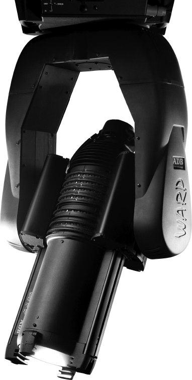
26 Technical Description Boards Description Names and location of the boards The drawing below defines each board (PCB) with his associated function. LEFT RIGTH PCB 1527 PCB XLR4 PCB 1527 RIGHT PCB 1525 PAN & TILT PCB MOTORS DRIVERS LEFT AMR SENSOR TILT COARSE PCB MOTORS DRIVERS RIGHT AMR SENSOR TILT FINE LAMP RELAY AMR SENSOR PAN COARSE AMR SENSOR PAN FINE POWER SUPPLY 24 VOLTS PCB 1496 MOTHER BOARD (TOP BOARD) FUSE HOLDER POWER ON DIRECT SUPPLY LAMP SUPPLY (EXTERNAL DIMMER) Service Manual - page 24

. 6.3.1.2 Description SPARE PART CODE 1001.65.")
27 Technical Description 6.3 General description The WARP/M is a motorized profile spotlight with 3 phase steppers on all functions. The user interface is accessible by the display and the buttons The control is by DMX512 and Ethernet (ArtDMX) Motherboard (Topbox board) Block scheme CPU is a Motorola 32 bit (ColdFire range) with on-chip peripherals including 2 UARTs and Ethernet. TCPIP stacks and web-page browser is running on LINUX. CPLD (Complex Programmable Logic Device) Description SPARE PART CODE LOCATION TOP BOX LINK 24 V Power Supply WARP Link 1 Ground Service Manual - page 25


28 Technical Description PCB 1494 Front: ESC BUTTON FUSE 3A ENTER BUTTON ERROR LED DMX LED DMX IN POWER LED DMX OUT ETHERNET Back: DISPLAY BUTTON - Important: 2 Last slots must be free BUTTON + ETHERNET LED 24 V DC INTERNAL DIMMER WARP LINK 1 Service Manual - page 26
29 Technical Description Functions: This board PCB 1496 is designed to: Receive / Send DMX 512 Translate DMX in WARP Protocol Ethernet communication Control and Supply of the Motor Boards Technician Interface (Display Menu) Control of built-in dimmer and ballast (for WARP/M/DIM and WARP/H/HMI) Update of software in other boards Components: Components you can change on this board are: Fuse 3A (spare part code ) Display (see front photo: 2 last slots are free) Power-up procedure: When you switch on the WARP/M 1. Only LED Power on 2. Wait approximately 30 s until all LED is on and Display write WARP or DMX- before motors resetting Service Manual - page 27


30 Technical Description Pan & Tilt driver board PCB 1525 The Pan and Tilt drive are driven by 3 phase steppers. The steppers are PWM (Pulse with modulated) controlled. We use a 1:10 belt drive reduction ratio to ensure a smooth Pan / tilt. The DSP is 8 bit processor dedicated to motor control. The DSP has a 10 channel A/D converter input and a 6 channel PWM generator Magneto-resistance sensors A high resolution, low power magneto-resistance sensor is used. The MR sensor is capable of measuring the angle direction of a magnetic field from a magnet. The MR sensor operates on 3 V with bandwidth response of 0 5 MHz Principe of operation (1) Anisotropic magneto-resistance (AMR) occurs in ferrous materials. It is a change in resistance when a magnetic field is applied in a thin strip of ferrous material. The magneto-resistance is a function of cos 2θ where θ is the angle between magnetization M and current flow in the thin strip. When an applied magnetic field is larger than 80 Oe, the magnetization aligns in the same direction of the applied field; this is called saturation mode. In this mode, θ is the angle between the direction of applied field and the current flow; the MR sensor is only sensitive to the direction of applied field. The sensor is in the form of a Wheatstone bridge (Figure). The resistance R of all four resistors is the same. The bridge power supply VS causes current to flow through the resistors, the direction as indicated in the figure for each resistor. HMC1512 is designed to be used in saturation mode.hmc1512 has two identical MR bridges, coexisting on a single die. Bridge B physically rotates 45 from bridge A. The HMC1512 has sensor output V=VSS sin (2θ) for sensor A and sensor B output VS=-VSS cos (2θ), where VS is supply voltage, S is a constant, determined by materials. (1) Honeywell Sensor products Service Manual - page 28
31 Technical Description Principe of operation by WARP/M The importance by WARP/M is accuracy and good repeatability on Pan / Tilt. WARP/M uses 2 magneto-resistance sensors for each motor. The gear box ratio between the 2 magneto resistance sensors gives an accurate measurement. The magneto-resistance sensors generate two 90 phase-shifted sinusoidal signals: A = VS (Oa+S sin (2θ)) B = VS (Ob+S cos (2θ)) Oa Offset voltage of the A bridge Ob Offset voltage of the B bridge S Conversion ratio of the sensor VS Bridge voltage supply and gain θ Angle of magnetic field Explanation of Pan by WARP/M The gear box ratio used by WARP/M is 1/10 for the pan motor, 5 motor turns are required to cover the entire span. This means 10 electrical revolutions for the first magneto-resistance sensors, and 1 electrical revolution (1/2 mechanical turn) for the second magneto-resistance sensor Magnetic sensors connector The sensor connector is a MOLEX mini-kk series 1 x 5 male connector, with the following wiring: V analog (3.3V) Sense1 Sense2 GND GND Service Manual - page 29


32 Technical Description Description SPARE PART CODE LOCATION Left Arm LINK Pan & Tilt Motor Boards WARP Link 3 4 AMR Sensor Lamp Relay Fuse for PAN Motor Fuse for TILT Motor TILT COARSE TILT FINE PAN COARSE LAMP CONTROL WARP LINK 3 PAN FINE Service Manual - page 30
33 Technical Description Functions: This board PCB 1525 is designed to: Control Pan and Tilt (magnet encoding) Control the lamp relay Components: Components you can change on this board are: Fuse 2A (spare part code ) Reset procedure: Absolute Positioning Mode In this mode, there is no resetting procedure. When you switch on the WARP/M, the board knows the exact Pan & Tilt position via the AMR sensors. Reset Mode This mode could be used if you have a problem with one AMR sensor. (See User Manual to change mode). In Reset mode, when you switch on the WARP/M, Pan and Tilt go to mechanical 0 position, then go to DMX Value. Service Manual - page 31


34 Technical Description 6.4 Wheels driver board PCB 1525 DSP (Digital signal processors) Opto sensor SFH 9210 Reflective Interrupter with VCSEL-Emitter Opto sensors connector GND 3V3 Sens1 Sens2 Sens3 Sens4 Sens5 Sens6 GND Service Manual - page 32


35 Technical Description Left 6 drivers Board PCB 1525 SPARE PART CODE LOCATION Left Arm LINK Shutters B & C WARP Link 2 & 3 IR Sensor Left Fuse Motor L1: Shutter B Fuse Motor L2: Shutter C Fuse Motor L3: Accessory 2 Fuse Motor L5: Shutter C Fuse Motor L4: Shutter B Fuse Motor L6: Zoom IR Sensor Connector WARP LINK 3 WARP LINK 2 Service Manual - page 33
36 Technical Description Functions: This board PCB 1525 is designed to: Control all Motors in the Left Motor Wing: Shutter B, Shutter C, Front Acc. And Zoom Components: Components you can change on this board are: Fuse 2A (spare part code ) Reset procedure: When you switch On the WARP/M, all shutter rings will turn automatically to the IR Sensor. When the Silvered index of the ring passes in front of the IR Sensor, the ring stops and goes back to the 0 position. If the ring doesn t stop in front of the IR sensor, the reset has failed. In this case, send a calibration as explain in the user manual. Service Manual - page 34

37 Technical Description Right 6 Drivers Board SPARE PART CODE LOCATION Right Arm LINK Shutters A & D WARP Link 1 & 2 IR Sensor Right DMX for CC changer Fuse Motor R6: Shutter A Fuse Motor R5: Shutter D Fuse Motor R4: Accessory 1 Fuse Motor R2: Shutter D Fuse Motor R3: Shutter A Fuse Motor R1: Focus IR Sensor Connector WARP LINK 2 DMX Out for Colour Changer WARP LINK 1 Service Manual - page 35
38 Technical Description Functions: This board PCB 1525 is designed to: Control all Motors in the Right Motor Wing: Shutter A, Shutter D, Rear Acc. And Focus Components: Components you can change on this board are: Fuse 2A (spare part code ) Reset procedure: When you switch On the WARP/M, all shutter rings will turn automatically to their IR Sensor. When the Silvered index of the ring pass in front of the IR Sensor, the ring stop and go back to the 0 position. If the Ring doesn t stop in front of the IR sensor, the reset has failed. In this case, send a calibration as explain in the user manual. Service Manual - page 36
39 Technical Description DMX Auxiliary connector (J1) This connector is only mounted on Shield board with the DMX option. The connector is a NEUTRIK NC4FAH (with lock) or NC4FAH-0 (without lock), with the following wiring: GND DMX 512 Data DMX 512 Data+ +24 VDC The +24 VDC power supply is issued from the internal motor power supply. It is protected through a 1A fuse (RAYCHEM Polyswitch) and filtered by a bypass capacitor. The DMX is not terminated nor polarized in the PCB. The board provides standard protection against electrostatic discharge (ESD) transients (up to 15kV for 100pF / 1,5kΩ model). 6.5 Warplink - Inter Board Communications Protocol The link consists of a single RS485 multi-drop bus. Each transceiver on the link is called a "station" Transceivers and Termination The link is not terminated since runs are short and configuration is a star, but it is biased at each station so that with transmitters switched off or with the link disconnected, a logical 1 is read. An effective circuit is shown in figure. In the closed system of the Warp there is no need for isolated transceivers. Slew rate limited transceivers should be used Medium A controlled impedance line is not necessary. However the data pair should be twisted if possible and steps must be taken to ensure that the two wires of the pair are kept close together throughout the run Byte Format The protocol uses the 9 bit communications scheme common in microcontrollers, bit 8 is a start of message flag. It is 1 for the first character of a frame and is otherwise 0. This first character is sufficient to indicate to receivers whether they have any interest in the ensuing message. If not, a receiver can revert to an idle mode pending the next start of frame character. Data format is 1 start bit, 8 data bits (LSB first), 1 Start of message flag, 1 Stop bit. Link data rate is 125kBaud WarpLink connectors The internal WarpLink connector is a HE14 1x10 connector, with the following wiring: GND +24V +24V +24V GND data B data A GND Spare 1 spare 2 Service Manual - page 37
40 Motorised Yoke 7 Motorised Yoke - Maintenance Sheet 7.1 Disassembling arm cover and LID for PAN Axis Required Tool(s) Spare Part Code Preliminary reading Screwdriver PZ None 1. Switch OFF and Unplug the WARP 2. Remove the 16 screws of ARM COVER 3. Remove the 4 screws of the LID PAN Axis Notice : To close Arm Covers, start with shoulder covers To Close PAN Shaft Cover, please use new metric screws PZ M4* includes: 2 Yoke cover shoulder 2 Yoke cover arm 1 Cover pan shaft 20 Screws M4*12 Service Manual - page 38
41 Motorised Yoke 7.2 Open / Replace TOP BOX Plate Required Tool(s) Spare Part Code Preliminary reading Torx T None 1. Switch OFF and Unplug the WARP 2. Lay the Motorised WARP on its side 3. Remove 14 screws of Top BoxPlate 4. Remove the Top Box Plate includes: 1 Top box plate feet assembly 14 Screws M6*16 Notice: You can re-use same screws to close top box Service Manual - page 39
42 Motorised Yoke 7.3 Open Motor Wing Required Tool(s) Spare Part Code Preliminary reading Screwdriver PZ2 Rivet Tool None 1. Switch OFF and Unplug the WARP 2. Remove the 20 screws Important: The first time your open Motor Wing; you have to replace all taptite screws by screws TCBC M4 x 12 Z.N DIN 7985-Z. For the right side, use drilled cover for XLR includes: 4 Motor cover 3 End cover 40 Screws M4*12 ZN includes: Complete XLR 4 Connector mounted on an end cover Thermo shrink sleeve 4 cable ties 10 Screws M4 * 12 ZN Service Manual - page 40
43 Motorised Yoke 7.4 Replace 24 V DC Power Supply Required Tool(s) Spare Part Code Preliminary reading Flat Screwdriver Screw driver PZ Chapter Switch OFF and Unplug the WARP 2. Disconnect 230 V INPUT + 24 V OUTPUT on the power supply (use PZ 2). 3. Remove the 2 screws (TCF UNC 6-32 length 10 mm) and replace Power Supply. 4. Before replacing 24 V Power Supply, put LOCTITE 243 on the screw 230 V Input includes: 3 Screws 1 24 V Power supply L N G N D 24 V Power Supply 24 V DC Output Blue Red Service Manual - page 41
44 Motorised Yoke 7.5 Replace Front Panel Required Tool(s) Spare Part Code Preliminary reading Flat Screwdriver Screwdriver PZ2 Wire Cutter Chapter 7.2 Chapter Remove External connector and Slide Lamp Wire through the Cable Gland 2. Disconnect 24 V Power in + WARP Link 1 + GND (from the Board) 3. Cut cable tie behind Top Board (which fixes WARP Link 1) 4. Disconnect 230 V Power IN from 24 V Power Supply 5. Replace the Front Panel includes: 1 Front panel assembly 3 cable ties Important: When you change the Front Panel Board, you have to enter the correct IP address by means of the WEB PAGE. The IP address is written on the label on the right Arm. If you replace only this board, you don t have to re-calibrate PAN&TILT 2 Do not disconnect from the Relay Board Service Manual - page 42
45 Motorised Yoke 7.6 Replace Top Board PCB Required Tool(s) Spare Part Code Preliminary reading Screwdriver PZ 0.75 Flat Screwdriver Open ended spanner Chapter 7.5 Chapter Remove 6 screws from XLR connectors (PZ 0.75) 2. Remove 3 screws (Flat) 3. Remove 3 spacers and 2 screws (Open ended spanner + Flat) 4. Change the board Important: When you change the Top Board, you have to enter the correct IP address by means of the WEB PAGE. The IP address is written on the label on the right Arm. If you replace only this board, you don t have to recalibrate PAN&TILT WARNING: If you replace the top box Board, you have to send it with the RMA correctly completed. The IP address of the WARP is written into the right Arm on a self adhesive label includes: 7 Screws M3*12 6 Screws M3*8 4 Spacers M3*8 6 Washers 2 Nut M3 1 Top Box Board Service Manual - page 43
46 Motorised Yoke 7.7 Change Motor Board Right Required Tool(s) Spare Part Code Preliminary reading Flat Screwdriver Wire Cutter Chapter 7.1 Chapter Switch OFF and Unplug the WARP 2. Disconnect from the Board: WARP Link 1 - WARP Link 2 - Magnetic Sensor XLR 4 3. Disconnect all motors and cut cable tie on the heat sink 4. Remove the 4 screws 5. Replace Right 6 Drivers Board (use new cable tie) MOTOR LABELS R4 R5 R6 R3 R2 R1 M1 M2 M3 M4 M5 M6 Important: Before switch on, remove accessories (iris, gobo, ) When you restart; all rings will calibrate includes: 1 Complete right Board 5 Screws M3*8 5 Washers 3 cable ties Service Manual - page 44
47 Motorised Yoke 7.8 Replace PCB Pan & Tilt Required Tool(s) Spare Part Code Preliminary reading Flat Screwdriver Chapter 7.1 Chapter Switch OFF and Unplug the WARP 2. Disconnect from the Board: All Magnet Sensor - Pan & Tilt Motors - WARP LINK 3 3. Remove the 4 screws 4. Replace the Board Important: When you restart the WARP, and after replacing this board, it is necessary to re-calibrate Pan & Tilt. This can be started from Web Page, Desk or local Display with the latest WARP SOFTWARE PAN & TILT CALIBRATION takes around 20 minutes WARNING Don t touch the YOKE during calibration If you touch YOKE, you have to restart a new calibration includes: 1 Complete Pan & Tilt board 2 drivers 5 Screws M3*8 5 Washers MOTOR LABELS PAN TILT M1 M2 M3 M4 M5 M6 Service Manual - page 45
48 Motorised Yoke 7.9 Replace PCB Shutter left Required Tool(s) Spare Part Code Preliminary reading Flat Screwdriver Chapter 7.1 Chapter Switch OFF and Unplug the WARP 2. Remove PAN & TILT Board (see MS W/M008) 3. Disconnect WARP Link 3,IR Sensor Cable 4. Disconnect all Motors 5. Remove the 4 screws 6. Replace the Board 6 Drivers includes: Complete left board 6 drivers 5 Screws M3*8 5 Washers Important: Before switch on, remove accessories (iris, gobo, ) When you restart ; all rings will calibrate MOTOR LABELS L3 L2 L1 L4 L5 L6 M1 M2 M3 M4 M5 M Service Manual - page 46
49 Motorised Yoke 7.10 Replace Lamp Relay Board Required Tool(s) Spare Part Code Preliminary reading Collet Chapter 7.1 Chapter Switch OFF and Unplug the WARP 2. Disconnect the 2 lamp cables 3. Remove Plastic Clip and Replace the Board includes: 1 PCB 1525 Board relay 5 Clips Note: With old version of relay board the lamp could flash when you switch on the WARP (with channel lamp at full) Service Manual - page 47
50 Motorised Yoke 7.11 Replace Top Box Handle Required Tool(s) Spare Part Code Preliminary reading Screwdriver PZ Chapter Switch OFF and Unplug the WARP 2. Remove the 4 screws M5x25 3. Replace HANDLE includes: 4 Handle Top Box 5 Screws M5*25 2 Top box handle fastening Service Manual - page 48
51 Motorised Yoke 7.12 Replace fine Pan AMR Sensor Required Tool(s) Spare Part Code Preliminary reading Screwdriver PZ Chapter 7.1 Chapter Switch OFF and Unplug the WARP 2. Disconnect Sensor Wire 3. Remove the 2 Taptite Screws from the Pan Suspension plate 4. Replace the Sensor Magnetic. Use new screws includes: 1 Sensor cable 3 Screws M3*10 3 Washers + 3 nuts 2 cable ties Important: The first time you replace AMR SENSOR, you have to replace all taptite screws by TCBC M4x8 ZN DIN 7985-Z When you re-start the WARP you have to re-calibrate PAN AXIS. This can be started from web page, desk or local display. Note: Distance between sensor and magnet should be around 1 mm Service Manual - page 49
52 Motorised Yoke 7.13 Replace Coarse PAN AMR Sensor Required Tool(s) Spare Part Code Preliminary reading Screwdriver PZ Chapter 7.1 Chapter Switch OFF and Unplug the WARP 2. Disconnect sensor wire 3. Remove the 2 Taptite screws 4. Replace the Sensor Magnetic using new screws includes: 1 Sensor cable 3 Screws M3*10 3 Washers + 3 nuts 2 cable ties Important: The first time you replace AMR SENSOR, you have to replace all taptite screws By TCBC M4x8 ZN DIN 7985-Z. When you re-start the WARP you have to recalibrate PAN AXIS. This can be started from web page, desk or local display Note: Distance between sensor and magnet should be around 1 mm. Service Manual - page 50
53 Motorised Yoke 7.14 Replace fine TILT AMR Sensor Required Tool(s) Spare Part Code Preliminary reading Screwdriver PZ Chapter 7.1 Chapter Switch OFF and Unplug the WARP 2. Disconnect sensor wire from Fine Tilt Sensor 3. Remove the 2 taptite screws 4. Replace the Sensor Magnetic using new screws includes: 1 Sensor cable 3 Screws M3*10 3 Washers + 3 nuts 2 cable ties Important: The first time you replace Fine Tilt AMR SENSOR, you have to replace all taptite screws by TCBC M4x8 ZN DIN 7985-Z. When you re-start the WARP you have to recalibrate Tilt Axis. This can be started from web page, desk or local display. Note: Distance between sensor and magnet should be around 1 mm Service Manual - page 51
54 Motorised Yoke 7.15 Replace Coarse TILT AMR Sensor Required Tool(s) Spare Part Code Preliminary reading Screwdriver PZ2 Wire Cutter Chapter 7.1 Chapter 7.7 Chapter includes: 1. Switch OFF and Unplug the WARP 1 Sensor cable 3 Screws M3*10 2. Remove Right Board (see chapter 7.7) 3 Washers + 3 nuts 3. Cut The cable tie and Disconnect Coarse Tilt sensor wire 2 cable ties 4. Remove the 4 taptite screws on the two sides of the arm. 5. Slide down the Sensor Plate until access all screws of the AMR Sensor 6. Replace the Magnetic Sensor using new screws 2 Important: The first time you replace Coarse Tilt AMR SENSOR, you have to replace all taptite screws By TCBC M4x8 ZN DIN 7985-Z. When you re-start the WARP you have to recalibrate PAN AXIS. This can be started from web page or desk or local display Note: Distance between sensor and magnet should be around 1 mm You have small windows on the arm side to inspect the sensor position Service Manual - page 52
55 Motorised Yoke 7.16 Replace TILT Belt Required Tool(s) Spare Part Code Preliminary reading Screwdriver PZ2 H Chapter 7.1 Chapter 7.7 Chapter Switch OFF and Unplug the WARP 2. Remove Right Board (see chapter 7.7) and the Fine AMR Sensor (see chapter 7.14) 3. Loose 4 screws on the Tilt Motor Suspension Plate 4. Slide up the Motor to get free the Belt 5. Remove the belt turning the Tilt axis includes: 1 Belt 2 Screws M3*108 2 Washers + 2 nuts 4 Important: If you remove the Fine Tilt Sensor, you have to replace all taptite screws By TCBC M4x8 ZN DIN 7985-Z. When you re-start the WARP after moving AMR Sensor, you have to recalibrate PAN AXIS. This can be started from web page or desk or local display : Loosen the 4 Screws 3 Service Manual - page 53
56 Motorised Yoke 7.17 Remove WARP from the YOKE Required Tool(s) Spare Part Code Preliminary reading WARP Key Screwdriver PZ2 AMP Pin Crimp AMP Pin Extract Tool Chapter 7.1 Chapter 7.2 Chapter Switch OFF and Unplug the WARP 2. Open Arms cover and Disconnect lamp cable into the left arm. 3. Use the special tool to extract pin from the AMP Connector, if not cut the cable 4. Remove Motor Wing Cover (see chapter 7.2) 5. Unplug and remove all Cables from Motor Wing through Tilt shaft (Motors, IR Sensor and XLR 4) 6. Loosen Nut Right and Left between Arms and Motor Wing 7. Slide the WARP through the Motor Wing Profile and pass lamp cable through the Tilt Shaft. Notice: If you haven t got a Pin Extract Tool, you can order spare part , which provides you new connector and crimp pin. So you can cut wire near the existing one and replace it to re-assemble the WARP. Direction of Arrow = to untighten includes: 4 Pins 1 Connector 5 cable ties 40 Screws M4*12 ZN Thermo shrink sleeve 4 cable ties Service Manual - page 54
57 Motorised Yoke 7.18 Remove Right Arm Required Tool(s) Spare Part Code Preliminary reading Hexagon Key4 Circlips Pliers 177 G 18 Wire Cutter Chapter 7.1 Chapter 7.7 Chapter includes: 1. Switch OFF and Unplug the WARP 1 Motor system housing tilt 2. Remove Right Board (see chapter 7.7) 11 Screws M6*10 10 Tie Rape 3. Remove all cable fixed by tie-rape on the right arm structure 4. Disconnect: Tilt Motor AMR Fine Tilt Sensor AMR Coarse Tilt Sensor 5. Remove Circlips, Tilt Shaft Plate and the nut 6. Remove the 10 screws on the two sides Replace the Motor Tilt Assembly 6 Tilt Shaft Plate Important: When you replace Tilt Shaft plate, place it in the right position. After this operation, you have to recalibrate the Tilt from desk or Web page with the last ADB software Service Manual - page 55
58 Motorised Yoke 7.19 Replace Tilt MOTOR Required Tool(s) Spare Part Code Preliminary reading Screwdriver PZ2 Hexagon Key Chapter Switch OFF and Unplug the WARP 2. Remove the 2 Taptite screws 3. Remove the 4 hexagon screws includes: 1 Tilt Motor assy 4 screws 4*12 4 Washers 3 Screws M3*10 + Nuts Service Manual - page 56
59 Motorised Yoke 7.20 REPLACE TILT SHAFT & Pulley Required Tool(s) Spare Part Code Preliminary reading Screw driver PZ2 Hexagon Key 3 Circlips Pliers Chapter Remove the Tilt Belt (see 7.16) 2. Remove the intermediate gear and slide out the Tilt Shaft 3. Remove Mechanical endless and the 3 screws 4. Open the pulley includes: 1 Tilt Axis Assembly 1 large Pulley Notice: Screws that have been glued in the factory can be released with a hot air fun, use hot air gun to unstuck them. Service Manual - page 57

60 Motorised Yoke 7.21 Remove Coarse TILT Ring Required Tool(s) Spare Part Code Preliminary reading Flat Screwdriver Metric Open ended spanner Chapter Put the screw driver into the axis to lock the position 2. Use the Open ended spanner to tighten the nut. 3. Remove the axis from the arm 4. Unclip the magnet from the Plastic Gear includes : 1 Magnet 1 ring 2 Washers 1 Screw 1 Nut 1 Circlip Notice: To clip a new magnet into the plastic gear, you can use silicone glue to lock it. Magnet Position for the New Magnet Service Manual - page 58
61 Motorised Yoke 7.22 Replace Motor Wing How to remove the Motor Wing Required Tool(s) Spare Part Code Preliminary reading Torx T30 None Chapter Remove the WARP from the Yoke (see chapter 7.17) 2. Remove the two Screws into the Motor Wing extrusion 3. Remove the motor wing (without change motor position) WARNING : When you remove the complete motor wing, DON T SLIDE MOTORS IN THE EXTRUDED BASE. Don t change motor positions. It would make to it harder to replace the complete motor wing. Service Manual - page 59
62 Motorised Yoke How to install the new Motor Wing Required Tool(s) Spare Part Code Preliminary reading Torx T30 None Chapter 7.17 WARNING: BEFORE REPLACE MOTOR WINGS, CHECK SIDE POSITION AS EXPLAINED IN CHAPTERS and Place the Motor Wing in the good side, with motors in correct position 2. Put the two screws through the motor wing, and screw them on the fastener inside arm profile (not tight, loosen screw) 3. Press as shown below and tighten screws (this procedure is needed to place IR sensor correctly in front of ring index). 3: Tighten 3: Tighten 1 1 2: Press 2: Press IMPORTANT: When you restart the motorised WARP, you have to calibrate all wheels. If calibration and reset failed, you have problem with IR sensor Position. In this case, it is not necessary to remove the WARP from the Motorised Yoke 1. Loosen Tilt Shaft nuts on the both side 2. Slide the WARP in the Yoke to access each motor Wing Screws 3. Loosen the 2 screws of the failed motor wing (Torx 30) 4. Use a plastic hammer and knock on the front end cover of the motor Wing 5. Re Tighten the 2 screws and nuts =If reset or calibration always failed, you have to change the IR Sensor Service Manual - page 60
63 Motorised Yoke Right Motor Wing position On the Right hand side of the WARP, you must see a screw head into to arm profile near the cassette filter, as shown below SHUTTER A SHUTTER D REAR ACCESSORY Screw head is present on right hand side REAR LENS Service Manual - page 61
64 Motorised Yoke Left Motor Wing position On the left hand side of the WARP, there is no screw head into to arm profile near the cassette filter, as shown below SHUTTER B SHUTTER C FRONT ACCESSORY No screw head on left hand side FRONT LENS Service Manual - page 62
65 Motorised Yoke 7.23 Remove Pan Motor Required Tool(s) Spare Part Code Preliminary reading Screwdriver PZ Chapter Remove Right Arm (see chapter 7.18) 2. Remove AMR Sensor Pan Fine (see chapter 7.12) 3. Loosen the 4 screws and Slide the motor to remove the belt 4. Remove the 4 screws and replace the Pan motor includes: 1 Pan Motor Assembly 4 Washers 4 Screws M4*12 3 Screws M3*10 + Nuts Service Manual - page 63
66 Motorised Yoke 7.24 Remove Yoke from Top Box Required Tool(s) Spare Part Code Preliminary reading WARP Key Flat Screwdriver None Chapter Remove Yoke from the Top Box 1. Remove top box Plate (see chapter 7.2) 2. Remove 24 V Power Supply (see chapter 7.4) 3. Remove Front Panel (see chapter 7.5) 4. Unplug ground cable from Pan shaft 5. Unlock the nut (bend the small plate) then remove the nut using WARP key. 6. Remove the Pan Shaft through the top box hole Service Manual - page 64
 Spare Part Code Preliminary")

 3. Slide the Top Box through the shaft with Opened Panel front of you 4.")

67 Motorised Yoke How to replace the motorised yoke on the Top Box Required Tool(s) Spare Part Code Preliminary reading WARP Key Flat Screwdriver None Chapter 7.5 To replace the PAN Belt 1. Put the Pan Motor on the right side 2. Turn anticlockwise the Pan shaft to the mechanical end stop (you must have 2 shaft slot horizontal) 3. Slide the Top Box through the shaft with Opened Panel front of you 4. Slide the lock plate and clamp the 2 bended part into the topbox 5. Grip the shaft nut with the WARP key 6. Replace the Pan Belt 7. Bend one of the lock plate strip to fix the nut 8. Pass trough the shaft and connect correctly: Security Cable WARP Link 1 Ground Cable Lamp Wire Left 1 Righ IMPORTANT: You Must Calibrate Pan Axis after this operation 4 Service Manual - page 65
68 Motorised Yoke 7.25 Replace Pan Belt and Coarse Gear Required Tool(s) Spare Part Code Preliminary reading Screw Driver PZ2 Circlips Pliers Flat Screwdriver Open Ended Spanner Chapter 7.24 Chapter 7.13 To replace the PAN Belt 9. Remove the Pan Coarse Sensor 10. Remove the 10 Taptite Screws from the Pan Housing 11. Remove the Circlpis 12. Slide down the Pan Housing 13. Replace the Pan Belt 14. Before place the new one, put it in the Pan Housing To replace the Coarse Gear 1. Put the screw driver into the axis to lock the position 2. Use the Open ended spanner to tighten the nut. 3. Remove the axis from the Pan Housing 4. Unclip the magnet from the Plastic Gear includes : 1 PAN Belt 12 Screws M4*8 (not Taptite) includes : 1 Complete Gear with Magnet 1 Nut + 1 Washer 1 Put the Belt into the housing before reassemble 1 2 Service Manual - page 66
69 Motorised Yoke 7.26 IR Sensor Required Tool(s) Spare Part Code Preliminary reading Screwdriver PZ Right Left Chapter Remove the Motor Wing from the WARP (see chapter 7.22) 2. Remove the 3 Screws from the motor Wing 3. Remove the Plate protection and the IR board. 4. Replace the board using new screws and nylon washers (one beneath and one above the board on each M3 Insert, put blue Loctite 243 on screws) Important: Don t forget Nylon Washer on each side of the board (can t work without) Take care of insulation above the board Notice: In factory, M3 screws are stop with Loctite Glue 243; if difficult to remove, use a hot air gun to un-stick includes: 1 IR Board Right with Insulation 4 Screws M3*6 PZ1 8 Nylon Washer includes: 1 IR Board Left with Insulation 4 Screws M3*6 PZ1 8 Nylon Washer Insulation sticker CAUTION: It is very important to respect motors and IR board setting (see chapter ) You must have a photoelectric cell in front of each gear Nylon Washers Service Manual - page 67
70 Motorised Yoke 7.27 IR Sensor Setting Following drawings show you motors and sensor setting. On this drawing you can find Spare Part Code if you need to change Motor. Left Motor Wing Left IR Board Spare code: Front Accessory Motor Spare Code : Zoom Motor Spare Code : Shutter C Bottom Spare Code : Shutter C Top Spare Code : Shutter B Bottom Spare Code : Shutter B Top Spare Code : Service Manual - page 68
71 Motorised Yoke Right Motor Wing Right IR Board Spare code: Rear Accessory Motor Spare Code : FOCUS Motor Spare Code : Shutter D Top Spare Code : Shutter D Bottom Spare Code : Shutter A Top Spare Code : Shutter A Bottom Spare Code : Service Manual - page 69


72 Motorised Yoke 7.28 Motor Wing Required Tool(s) Spare Part Code Preliminary reading Open Ended Spanner 5.5 Flat Screw Driver Screw driver PZ2 None Chapter 7.3 Chapter Remove Wing Covers on each motor wing (see chapter 7.3) 2. Unplug motors you wish replace 3. Remove the locking plate on each side of the motor wing 4. To remove a motor, push it against the wing profile and slide it to the near end Locking Plate Service Manual - page 70
73 Motorised Yoke 7.29 Change motor Gears Required Tool(s) Spare Part Code Preliminary reading Hexagonal key Chapter Change with motors outside 1. Remove 2 screws in the small gear 2. Slide out the 2 gears in same time 3. Replace gears (use Loctite 243 for the 2 screws) You can change gears with motors on Motors Wing 1. Remove locking plate under the gears motor you want change 2. Remove the 2 screws from the small gear. 3. Push the Motor assembly against the motor Wing to disconnect from wheels. 4. Remove the 2 gears at same time includes : 8 Shutter gears 2 Accessory gears 2 Lens Gear 12 small Gears 26 Screws M3*4 WARNING: Gears Setting are different between shutters / accessory / lenses motor assembly. For shutters, you have a Top and a Bottom setting, please refer to chapter Service Manual - page 71
74 Motorised Yoke 7.30 Adjust Motors in the motor Wing Required Tool(s) Spare Part Code Preliminary reading Open Ended Spanner 5,5 Flat Screw Driver Screw driver PZ2 None Chapter 7.28 IMPORTANT When you remove the locking plate for maintenance, you have to adjust it before fixing and start the WARP. It is very important to get free each motor to ensure a well working. 1. Loosen the 2 screws of the locking plate (you can move it through the 2 obround) 2. Adjust the locking plate position to leave 1 mm between it and all motors. 3. Tighten the 2 screws. 4. Control adjustment => Put the head up, Power on the WARP and control all reset 1 mm When you press here, all gears must turn when you move the WARP Ring. Service Manual - page 72


75 Motorised Yoke 8 WARP HEAD - Maintenance Sheet 8.1 How to change the lamp assembly How to remove the old lamp Assembly Required Tool(s) Spare Part Code Preliminary reading Wire Cutter Flat Screw Driver Screw Driver PZ Chapter 7.1 Chapter 7.3 Before Change the lamp Assembly Unplug the WARP and remove the lamp: 1. Unplugged the Motorised WARP and remove the Lamp 2. Remove Left Arm Cover and Left Motor Wing Cover 3. Unplug Lamp Cable from the Relay Board (see chapter 6,1) 4. Cut All cable ties which fit the lamp wire from the PCB relay to the Tilt shaft 5. Cut the cable near the 3 pts connector. 6. Slide the old wire through the Tilt Shaft 7. Open the Lamp Holder 8. Keep the security cable on the peak and flat cylinder 9. Remove it from the old lamp assembly (screw which fix the earth wire) includes: 1 complete lamp assembly (with grip on wire) 4 M3 * 10 Taptite+ 1 M3*6 2 Finger screws + springs 10 cable ties 1 x 3-pole connector Service Manual - page 73
76 Motorised Yoke How to place the new lamp Assembly 4 - Pass the safety cable through the Lamp Cable hole of the new lamp handle. 5 - Fix the safety cable on the new lamp Assembly, using the Screw M3*6 (put the washer between lamp plate and earth wire). Spring Finger Screw 6 - Unclose the new Lamp Assembly using the 4 black taptite screws. 7 - Screw the 2 Finger Screws with the 2 springs. Service Manual - page 74
77 Motorised Yoke 8.2 Remove / Change the light Box Required Tool(s) Spare Part Code Preliminary reading Hexagonal H Unplug the WARP and remove the lamp: 2. Remove the WARP from the motorised Yoke (see chapter 7.17) 3. Remove the 2 screws into the rings compartment using H4 4. Remove / Replace the Light Box and the 4 Plastic spacers Chapter 7.17 Chapter WARNING: Don t forget the 4 plastic spacers when you replace the light Box includes: 1 complete light box 2 Screws M5 * nuts 4 plastic Spacers 10 cable tie 1 x 3-pole connector Plastic Spacer Service Manual - page 75
78 Motorised Yoke 8.3 Replace the Reflector Required Tool(s) Spare Part Code Preliminary reading Hexagonal H4 Pozidrive PZ Chapter Unplug the WARP and remove the lamp: 2. Remove the Light Box from the WARP (see Chapter 8.2) 3. Remove the 2 Cones for heat 4. Remove screws M3 on the Front of the cone (PZ2) 5. Remove Screws H4 on the back (near the Peak and Flat) 6. Open the Light box 7. Replace the Reflector includes: 1 reflector 4 reflector Springs 2 Screws M 3 * washers 2 Nuts M3 auto block 1 connector 3pts and 3 crimps 4 WARNING: First Time you change the reflector, you have to replace taptite screws (front of the sink) by screws M3*12 (provided with spare parts ) Cone for Heat Reflector Spring Service Manual - page 76
79 Motorised Yoke 8.4 Change the Rings Compartment Required Tool(s) Spare Part Code Preliminary reading Metric Open ended spanner 13 Screw Driver PZ2 Hexagonal H 4 Hexagonal H Chapter How to Remove arms from the Ring Compartment 1. Unplug the WARP and remove the lamp: 2. Remove the WARP from the Motorised WARP (see chapter 7.17) 3. Remove Lenses Covers (see chapter 8.12) 4. Remove the light Box (see chapter 8.2) 5. Remove the Front Filter Cassette (see chapter 8.11) 6. Remove Diaphragm (see chapter 8.13) 7. Remove the 4 screws in the back of the Ring compartment 8. Remove the 2 arms includes: 1 complete Ring Compartment 2 screws M3*8 for Lenses Cover 2 screws M6*30 + Washers for Front Cassette 4 screws and washer to fix Arms on ring compartment 2 screws and washers for Belt Clip. Service Manual - page 77
80 Motorised Yoke How replace the Ring Compartment on a Motorized WARP Prepare Rings position for WARP/M Before replace ring compartment, you have to prepare the ring position as describe: Place the ring compartment to see pressed slider of the ring spacer on your right. BACK LEFT SIDE RIGHT SIDE: You must see pressed slider FRONT Service Manual - page 78

81 Motorised Yoke Place all graduated wheels as describe: LEFT SIDE FRONT RIGHT SIDE A Caution: Rings Positions are different between WARP/M and WARP/M B RING SHUTTERS ACCESSORIES FOCAL ZOOM POSITION You must see all white index, all shutters rings at ZERO You must see all white index, all accessories rings at ZERO You must place the ring at Position G and you must see the white index on your right front of you (detail A) You must place the ring between 11 and 12 and you must see the white on back side (detail B) Service Manual - page 79
82 WARP Head WARP Head Introduce Rings Compartment between lenses Arm on the WARP/M Put the cassette filter down and lenses arm up 2. Slide down Zoom and Focal lenses 3. Check all rings position (as describe on chapter ) 4. Introduce Arms into the Ring compartment (Take care that small gears are correctly connected to the lenses Ring) Service Manual - page 80

83 WARP Head How replace the Ring Compartment on a Motorized WARP Prepare Rings position for WARP/M Before replace ring compartment, you have to prepare the ring position as describe: Place the ring compartment to see pressed slider of the ring spacer on your right. BACK LEFT SIDE RIGHT SIDE: You must see pressed slider FRONT Service Manual - page 81

84 WARP Head WARP Head Place all graduated wheels as describe: LEFT SIDE FRONT RIGHT SIDE A Caution: Rings Positions are different between WARP/M and WARP/M B RING SHUTTERS ACCESSORIES FOCAL ZOOM POSITION You must see all white index, all shutters rings at ZERO You must see all white index, all accessories rings at ZERO You must place the ring near the D Position and the white index must be on your right (hide by aluminium part) (detail A) You must place the ring near the 7 Position and you must see the white on back side (detail B) Service Manual - page 82
 4.")
85 WARP Head Introduce Rings Compartment between lenses Arms on the WARP/M Put the cassette filter down and lenses arm up 2. Slide down Zoom and Focal lenses 3. Check all rings position (as describe on chapter ) 4. Introduce Arms into the Ring compartment (Take care that small gears are correctly connected to the lenses Ring) Service Manual - page 83
86 WARP Head WARP Head 8.5 Replace the Back Lens on WARP Required Tool(s) Spare Part Code Preliminary reading Flat Screw Driver Screw Driver PZ Chapter Unplug the WARP 2. Open the two lenses cover 3. Remove the Diaphragm (see chapter 8.13) 4. Put Front and back lenses at Full 5. Remove the 3 taptite screws from the Lens plate 6. Remove the 3 Isolations and the ADB Clip 7. Change the Lens includes: Back Lens New screws 3 Isolations 3 ADB Clip. Service Manual - page 84
87 WARP Head 8.6 Replace the Front Lens on WARP Required Tool(s) Spare Part Code Preliminary reading Flat Screw Driver Screw Driver PZ Chapter Unplug the WARP 2. Open the two lenses cover and remove the diaphragm (see chapter 8.13) 3. Put Front and back lenses at 0 4. Remove the 9 Taptite Screws and the front lens plate 5. Remove the 2 screws and the 2 spacers 6. Remove the 4 isolations and Clips 7. Change the Lens includes: Front Lens New screws for Lens plate 4 Isolations 4 ADB Clip 2 Screws Service Manual - page 85
88 WARP Head WARP Head 8.7 Replace the Back Lens on WARP Required Tool(s) Spare Part Code Preliminary reading Flat Screw Driver Screw Driver PZ Chapter Unplug the WARP 2. Open the two lenses cover 3. Remove the Diaphragm (see chapter 8.13) 4. Put Front and back lenses at Full 5. Remove the 3 taptite screws 6. Remove the 3 Isolations and the ADB Clip 7. Change the Lens includes: Back Lens New screws 3 Isolations 3 ADB Clip Service Manual - page 86
89 WARP Head 8.8 Replace the Front Lens on WARP Required Tool(s) Spare Part Code Preliminary reading Flat Screw Driver Screw Driver PZ Chapter Unplug the WARP 2. Open the two lenses cover 3. Put Front and back lenses at 0 4. Remove the 3 screws 5. Remove the 3 isolations and Clips 6. Change the Lens includes: Front Lens New screws 3 Isolations 3 ADB Clip Service Manual - page 87
90 WARP Head WARP Head 8.9 Change Gears & Belts on Required Tool(s) Spare Part Code Preliminary reading Flat Screw Driver Screw Driver PZ Chapter Important: On the WARP you have to remove Arms to change all gear and belt. To replace Arms correctly, please see chapter for and chapter for Unplug the WARP 2. Remove arms from WARP (see chapter 8.4.1) 3. Use Open ended spanner 10 to replace gear shafts & include: 2 Belts T3 * Belt Clip Screw washer and nut for Belt Clip 4 Ball Bearing Gears and Washer 2 gear Shaft 8 Washers M Service Manual - page 88
91 WARP Head 8.10 Replace Teflon Ring Required Tool(s) Spare Part Code Preliminary reading Flat Screw Driver Screw Driver PZ Chapter 8.11 Important: After a few years of operation, it could be necessary to change the Teflon ring to facilitate the sliding of the lenses. 1. Unplug the WARP 2. Open Covers and remove Filter Cassette (see chapter 5.12) 3. Remove Diaphragm (see chapter 5.14) 4. Unlink the 2 lenses from belts (remove screws and nuts from the belt clip) 5. Slide and remove completely lenses support from arms 6. Change all Teflon parts as initially assembled on each lens support 7. Replace lenses into arm profile 8. Replace Diaphragm Filter Cassette and covers WARNING: DON T Remove clip from belts if not you have to put correctly as written on chapter 8.4.2) includes: 10 Lens Stears 5 Lens Opened Stears 3 Lens Gliders Glider Service Manual - page 89
92 WARP Head WARP Head 8.11 Remove / Change Front Filter cassette Required Tool(s) Spare Part Code Preliminary reading Screw Driver PZ2 Hexagonal H None 1. Unplug the WARP 2. Open the two lenses cover 3. Remove the 2 screws M6 on the front 4. Remove the Filter Cassette includes: 1 Complete Filter Cassette 2 screws M6 * 30 2 Locking Washers 2 Safety Wire Attachment WARNING: Due to mechanical adjustment, some WARP were manufactured with a small sheet spacer between the filter cassette and arms. Don t forget the Safety Wire Attachment Before you remove the cassette, make note of the spacer position, to replace it correctly. Service Manual - page 90
93 WARP Head 8.12 Replace Lenses Cover Required Tool(s) Spare Part Code Before refer to: Rivet Grip (12-30 ) (22-50 ) None 1. Unplug the WARP 2. Drill the 2 rivets on Lenses cover with a drill diam. 3.2 mm 3. To install new covers, use new rivets (provided) includes: 2 complete Covers 3 black rivets includes: 2 complete Covers 3 black rivets Service Manual - page 91

94 WARP Head WARP Head 8.13 Replace Diaphragm Required Tool(s) Spare Part Code Before refer to: Screwdriver PZ Unplug the WARP 2. Open the two lens covers 3. Press on diaphragm arms and remove it from ring compartment. None Diaphragm Press here includes: 1 Diaphragm includes: 1 Diaphragm Press here Diaphragm Service Manual - page 92
TROUBLESHOOTING GENERAL SOFTWARE UPLOAD. Troubleshooting 1
 TROUBLESHOOTING GENERAL FIXTURE DOES NOT RESET Blown fuse: LEDs on the printed circuit board light up to indicate the power supplies are working. Check / replace the fuses on the circuit board if one or
MAINTENANCE OF PR MOVING HEADS
 MAINTENANCE OF PR MOVING HEADS General Maintenance 1.Structure 2. Trouble Shooting 3. Cleaning And Lubrication Structure Structure of Moving Head Head Arm Base Structure Base Main PCB Magnetic ballast
Overview of operation modes
 Overview of operation modes There are three main operation modes available. Any of the modes can be selected at any time. The three main modes are: manual, automatic and mappable modes 1 to 4. The MapDCCD
Quick Reference Guide. English EN Español ES Français FR Nederlands NL
 Quick Reference Guide English EN Español ES Français FR Nederlands NL Rogue R1 FX-B QRG EN About This The Rogue R1 FX-B Quick Reference Guide (QRG) has basic product information such as connection, mounting,
MOVING HEAD. User manual CAUTION!
 TM MOVING HEAD OBY-3 User manual CAUTION! contents Features Description of the appearance Inspection. Safety instructions Lamp Installation Rigging Connection with the mains Linking Instruction for gobo
FL-2R MOVING HEAD 120W
 FL-2R MOVING HEAD 120W USER MANUAL Ver1.0 Table of contents 1. Preface 1.1 Packing list 1.2 Unpacking instructions 1.3 AC Power 1.4 Safety instructions 2. Introduction 2.1 Features 2.2 DMX channel 3. Setup
CENTROIDTM. AC Brushless Drive. Product Spec Sheet
 4 Axis, up to 2 KW motors Brake Output for each axis Overtemp and Overcurrent Protection All-software Configuration Self-cooled Fiber Optic Control CENTROIDTM AC Brushless Drive Product Spec Sheet AC Brushless
Wolverine Turn Signal / Horn Kit 2102
 All years Yamaha Wolverine STOP - THIS KIT IS DESIGNED SPECIFICALLY FOR ALL YEAR AND MODELS YAMAHA WOLVERINE. IF YOUR MACHINE IS NOT ONE OF THESE MODELS DO NOT PROCEED. Contact Ryco Motorsports or your
Operating Instructions. Angle Seat Control Valve. Type 7020
 Operating Instructions Angle Seat Control Valve Type 7020 With: Digital Positioner Type 8048 Electro-pneumatic Positioner Type 8047 Pneumatic Positioner Type 8047 Version: 02/2006 Manual-7020e.doc Art.-No:
To Purchase This Item, Visit BMI Gaming
 Table of Contents General Operation. 3 How Slam-A-Winner plays How the Wheel Scores How the Ball Lift works Programming Options... 4-6 Troubleshooting Guide. 7-8 Parts Identification 9 Schematics 10-13
Operating Instructions. Pneumatic Control Valve Low Temperature. Type Series GS3
 Operating Instructions Pneumatic Control Valve Low Temperature Type 8026 Series GS3 With: Digital Positioner Type 8048 Electro-pneumatic Positioner Type 8047 Pneumatic Positioner Type 8047 Version: 03/2006
2016 HONDA 1000 Pioneer PN 3102 Turn signal / horn kit rev nc
 2016 Honda 1000 Pioneer STOP - THIS KIT IS DESIGNED SPECIFICALLY FOR 2016 HONDA 1000 PIONEER IF YOUR MACHINE IS NOT THIS MODEL DO NOT PROCEED. THIS KIT DOES NOT WORK ON THE PIONEER 500 nor 700 S. Contact
FD 120 Card Cutter MAINTENANCE MANUAL. MyBinding.com 5500 NE Moore Court Hillsboro, OR Toll Free: Local: /2011
 FD 120 Card Cutter 5/2011 MAINTENANCE MANUAL SAFETY PRECAUTIONS Always observe the cautions and warnings given below to prevent personal injury or property damage. The degree of danger and damage that
Documents: See next pages
 Stratos MSR 700/2 Moving luminarie The Stratos 700 MSR is a hi-res(8 bit or 16 bit) moving luminaire that becomes a full automated lighting system that offers limitless possibilites for theatre,film,commercial
Compact LED profile with zoom
 Compact LED profile with zoom 2 11 TABLE OF CONTENTS SAFETY / GENERAL INSTRUCTIONS INTRODUCTION Features Specifications OVERVIEW Rear view Top view MOUNTING CONTROL MENU OVERVIEW Control Panel Function
OBY-5. User manual MOVING HEAD CAUTION!
 TM MOVING HEAD OBY-5 User manual CAUTION! contents Features Description of the appearance Inspection. Safety instructions Lamp Installation Rigging Connection with the mains Linking Instruction for gobo
ONE TOUCH CONTROL BOX
 ONE TOUCH CONTROL BOX CONVERSION KIT INSTRUCTIONS REMOVAL, INSTALLATION, OPERATION, AND REMOTE CONTROL PROGRAMMING THUNDERSTONE PART #101322 REVISION A JULY 14 TH 2016 2 P a g e INSTALLING THE THUNDER
VECTRIX VX-2 SERVICE MANUAL. Version 1.0/May 2011 VECTRIX, LLC
 www.vectrix.com CONTENTS SECTION A: Tools 1 Tools Needed SECTION B: Mechanical Parts 1 Front Fairing 2 Front Console Cover 3 Speedometer Cover 4 Front Vertical Panel Cover-Lower 5 Front Vertical Panel
Table of Contents. Timer Identification Timer ID BLU-U Features: 1K 6K BLU-U Features 1K 6K
 DUSA Pharmaceuticals, Inc. Table of Contents Go to Chart # Timer Identification Timer ID BLU-U Features: 1K 6K BLU-U Features 1K 6K BLU-U Features: 10K BLU-U Features 10K BLU-U Symptom Fans Running, Timer
Wiring diagrams on page 29 are for reference only. For detailed vehicle wiring refer to Navistar documents.
 1 10/2014 REV 7 !!Attention!! Before performing diagnostics: Wiring diagrams on page 29 are for reference only. For detailed vehicle wiring refer to Navistar documents. Check for Fault Codes using the
Power Operated Retrofit Kit for Manual Door 230 VAC or 440/480 VAC 50/60 Hz Installation and Setup Manual
 Therm-L-Tec Building Systems LLC Therm-L-Tech Power Operated Retrofit Kit for Manual Door 230 VAC or 440/480 VAC 50/60 Hz Installation and Setup Manual Rev. A 10/2014 Index Index 1 Electrical Requirements
Portable Pack USER MANUAL
 se nsor Portable Pack USER MANUAL Contents Introduction...3 SP6 face panel components... 3 SP12 face panel components... 4 Electronics modules...5 Removing...5 Dimmer modules...6 Circuit breakers...6 LEDs...6
Elektralite LED Pro Line Pancake USER MANUAL (Version 2)
") Elektralite LED Pro Line Pancake USER MANUAL (Version 2) ElektraLED (a division of Group One), 70, Sea Lane, Farmingdale, NY11735, U.S.A. T. +1 (516)-249-3662. F. +1 (516)-249-8870 WWW.ELEKTRALED.COM 1.
Elektralite LED Pro Line Pancake USER MANUAL (Version 2) ElektraLED (a division of Group One), 70, Sea Lane, Farmingdale, NY11735, U.S.A. T. +1 (516)-249-3662. F. +1 (516)-249-8870 WWW.ELEKTRALED.COM 1.
Trouble Shooting a Jouan C/CR4.22 Centrifuge
 The world leader in serving science Trouble Shooting a Jouan C/CR4.22 Centrifuge No Spin Condition Erratic Speed Control No Cooling General Parts List Wiring Diagram No Spin Condition (Removing the Front
Turn Signal / Horn Kit PN 7101 by All years Polaris RZR 1000 and RZR 900, 900-4, 900 trail, 900S and 900XC STOP - THIS KIT IS DESIGNED
 All years Polaris RZR 1000 and 1000-4 2015 RZR 900, 900-4, 900 trail, 900S and 900XC STOP - THIS KIT IS DESIGNED SPECIFICALLY FOR ALL YEAR AND MODEL POLARIS RZR 1000 AND 1000-4. ALSO THE 2015 POLARIS RZR
PRODUCT INFORMATION BULLETIN #3365 DIGITAL MOTOR CONTROL PLATTER SYSTEMS For Serial Number and After
 PRODUCT INFORMATION BULLETIN #3365 DIGITAL MOTOR CONTROL PLATTER SYSTEMS For Serial Number 28640996 and After Record Platter System Identification Numbers Here: Model # Serial # Table of Contents Program
1.0 Features and Description
 1.0 Features and Description The is an intelligent actuator designed for precise control of quarter turn valves and dampers. Using stepper motor technology, the SmartStep proportionally positions valves
SX1000 Service Manual SALES: CUSTOMER SERVICE:
 SX1000 Service Manual SALES: 800-278-3933 CUSTOMER SERVICE: 800-745-1373 Revision: August 1999 Table of Contents Section Page I. Overview 2 II. Troubleshooting Tables 3 III. Maintenance Procedures Procedure
ECO Spot 2500 User Manual
 ECO Spot 2500 User Manual Thank you for choosing an ECO Spot 2500 Profile Spot. The projector part is based on a modified ETC Source Four and most of the available standard Source Four equipment, such
ECO Spot 2500 User Manual
 ECO Spot 2500 User Manual Thank you for choosing an ECO Spot 2500 Profile Spot. The projector part is based on a modified ETC Source Four and most of the available standard Source Four equipment, such
X24 Projector Original Instructions
 X24 Projector Original Instructions www.rosco.com (Revision: Feb2015) TABLE OF CONTENTS Introduction... 3 Warnings...... 4 Modules...6 Base Unit... 6 Wheel Module... 8 Lens Module...10 Analog Control Panel...11
ENGINE DISPLACEMENT 2000 NUMBER OF VALVES 16 ENGINE SET NUMBER
 MANUFACTURER Subaru TYPE Forester ENGINE DISPLACEMENT 2000 NUMBER OF VALVES 16 ENGINE CODE / NUMBER FA20 DIT VEHICLE CATEGORIES M TRANSMISSION AT VERSION Direct LiquiMax-2.1 PETROL ECU MANUFACTURER / CODE
User s Manual. Automatic Switch-Mode Battery Charger
 User s Manual Automatic Switch-Mode Battery Charger IMPORTANT Read, understand, and follow these safety rules and operating instructions before using this battery charger. Only authorized and trained service
EPS/ELA-Series User Manual EPS/ELA 250W
 EPS/ELA-Series User Manual EPS/ELA 250W EPS Stromversorgung GmbH Tel: +49 (0)821 570451 0 Index 3 Page: 1 Table of contents: Page 1. Features of ELA-Series... 3 1.1 Basic Functions... 3 1.2 Options...
KENSUN HID AUTOMOTIVE HEAD LAMP CONVERSION KIT INSTALLATION MANUAL
 1 KENSUN HID AUTOMOTIVE HEAD LAMP CONVERSION KIT INSTALLATION MANUAL 2 CONTENTS A. Before Installing B. Installing the Bulbs C. Installing the Ballasts D. For Bi Xenon Only: Installing the Relay Harness
SHARPY SPARE PARTS FINDER
 This document contents helps finding the spare parts numbers more frequently needed and includes useful information on them. INDEX. ELECTRONIC BOARDS... 2 2. WIRING HARNESSES... 3 3. MOTORS... 3 4. FANS...
Kelly HSR Series Motor Controller with Regen User s Manual V 3.3. Kelly HSR Opto-Isolated Series Motor Controller with Regen.
 Kelly HSR Opto-Isolated Series Motor Controller with Regen User s Manual HSR72601 HSR72801 HSR12401 HSR12601 HSR12901 HSR14301 HSR14501 HSR14701 Rev.3.3 Dec. 2011 Contents Chapter 1 Introduction... 2 1.1
1- Select the best mounting location
 Wixey TM REMOTE ROUTER READOUT MODEL WR525 Type 2 INSTRUCTIONS NOTE: Always turn off the power and unplug your machine before installing the WR525 1- Select the best mounting location The WR525 can be
MINISCAN ENGLISH INSTRUCTION MANUAL POWER SUPPLY AND INTERFACE INSTALLING THE PROJECTOR. 1.0 m HTI 300 ENGLISH
 ENGLISH MINISCAN HMD HTI HTI INSTRUCTI MANUAL IMPORTANT: Read carefully. It is essential for the correct and safe use of the equipment that erectors and operators should be fully conversant with the information
BIODEX SURGICAL C-ARM TABLES SERVICE MANUAL and and
 SURGICAL C-ARM TABLES SERVICE MANUAL 058-800 058-805 058-810 058-815 058-800 and 058-805 058-810 and 058-815 FN: 05-388 Rev A 6/16 BIODEX Biodex Medical Systems, Inc. 20 Ramsey Road, Shirley, New York,
Operation Manual. Mega 4Bank DMX Universal
 Operation Manual Mega 4Bank DMX Universal Part No. 3100078 Rev A 11-18-2014 System CFX-9604 CFX-7204 8ft Mega 4Bank Fixture 6ft Mega 4Bank Fixture MTP-K81 Kino 81 Mount w/ Junior Pin (28mm) X19-25M Mega
Therm-L-Tec Building Systems LLC. Therm-L-Tech. Power Operated Retrofit Kit 230 VAC or 440/480 VAC 50/60 Hz Installation and Setup Manual
 Therm-L-Tec Building Systems LLC Therm-L-Tech Power Operated Retrofit Kit 230 VAC or 440/480 VAC 50/60 Hz Installation and Setup Manual Rev. A 01/2015 Index Index 1 Electrical Requirements for Therm-L-Tec
Dycon D2430 EN54-4 Fire Alarm Power Supply Series
 Dycon D2430 EN54-4 Fire Alarm Power Supply Series Technical Description Installation and Operating Manual Construction Product Regulation 0359-CPR-00434 Page 1 of 14 Contents 1. General... 3 1.1 Product
Installation and Operation Guide. Tundra HD 2500 Power Inverter. for the. Webasto BlueCool Truck System
 Installation and Operation Guide Tundra HD 2500 Power Inverter for the Webasto BlueCool Truck System www.tundrainternational.com www.techwebasto.com BCTSP0063A Table of Contents 1. Introduction 4 1.1 Disclaimer.................................................................................
Go-ped ESR750 / ESR750EX Rear Brake Installation Instructions
 Go-ped ESR750 / ESR750EX Rear Brake Installation Instructions This kit provides all the parts you need to install a rear brake on your ESR750 or ESR750EX. It will not work on an ESR Sport, or other Go-ped
Assembly Instructions MP-P2 Power Supply and Chassis Base Plate
 Assembly Instructions MP-P2 Power Supply and Chassis Base Plate The MP-P2 Power Supply is the supply designed to power the mother board and its complement of plug-on boards including the MP-09 Microprocessor
Users Manual. Defender 1 8.0KW to 14.0KW Online Emergency Lighting Inverter. Technical Manual # Revision B
 Users Manual Defender 1 8.0KW to 14.0KW Online Lighting Inverter Technical Manual #018-0102-01 Revision B Phone: 1.877.DSPM.POWER 1.877.377.6769 Fax: 909.930.3335 Website: www.dspmanufacturing.com E-Mail:
minipointe Light source Osram Sirius HRI 140 W RO Light output lm, m Zoom range 3 fixed beam
 minipointe MiniPointe is a tiny agile air cutter specifically designed to produce sharp beam and aerial effects especially in venues constrained by size. Striking bright 0 parallel beams with glowing colours
OPERATION MANUAL Common for All models Bobbin Sensor (Weft End Detection) DP150 - L2 BP150 - L2-12V BP150 - L2-24V (PNP/NPN)
 DP150 - L2 BP150 - L2-12V BP150 - L2-24V (PNP/NPN)") OPERATION MANUAL Common for All models Bobbin Sensor (Weft End Detection) DP150 - L2 BP150 - L2-12V BP150 - L2-24V (PNP/NPN) Beta Computronics pvt. Ltd. 10/1 IT Park, Parsodi, Nagpur-440022 (MS), INDIA.
OPERATION MANUAL Common for All models Bobbin Sensor (Weft End Detection) DP150 - L2 BP150 - L2-12V BP150 - L2-24V (PNP/NPN) Beta Computronics pvt. Ltd. 10/1 IT Park, Parsodi, Nagpur-440022 (MS), INDIA.
Horizontal movement (PAN) Vertical movement (TILT) PAN/TILT speed. PAN/TILT function. Shutter, strobe function. Shutter, strobe
 Vertical movement (TILT) PAN/TILT speed. PAN/TILT function. Shutter, strobe function. Shutter, strobe") The colors, color- and gobo-wheel positions of the following DMX protocol are arranged as shown in the graphic. DMX protocol St. 28 Ch. Mode/Channel Value Feature Ex. 29 Ch. Ba. 1 8bit 19 Ch. Ba. 2 16bit
The colors, color- and gobo-wheel positions of the following DMX protocol are arranged as shown in the graphic. DMX protocol St. 28 Ch. Mode/Channel Value Feature Ex. 29 Ch. Ba. 1 8bit 19 Ch. Ba. 2 16bit
Sprayer Control. Manual for SprayLink Cable Installations. Tank. Jet Agitator. Agitator Valve. Diaphragm Pump. Pressure Transducer.
 Sprayer Control Plumbing & Installation Manual for SprayLink Cable Installations Tank Jet Tank Shut-Off Diaphragm Pump Electric Ball s Transducer Strainer Relief Regulating Copyrights 2012 TeeJet Technologies.
2005 and 09 Mustang install instructions Sequential / Chase Unit Partial Plug-N-Play Kit Meter4it Eng. Updated: 3/28/09
 Updated: 3/28/09 Verify content of kit: 1- Unit with wiring harness 1- Red power wire with 15 amp fuse 1- Color instruction 2- Velcro for mounting 1-Driver taillight harness 1- Passenger taillight harness
Foreword and disclaimer:
 Installation guide for the ADA Depot MDRT transformer. Foreword and disclaimer: Thank you for purchasing this Machinator transformer kit. These kit suites the MP-1,/ MB-1. This kit also solves the famous
10260 Retrofit to 10260A Non-Contact Sensor Instructions Kits through -512
 10260 Retrofit to 10260A Non-Contact Sensor Instructions Kits 51404974-501 through -512 Document Number Form: 62-86-33-16D Effective: 3-1-01 Supersedes: 11-00 Summary Retrofitting your 10260 actuator from
Build your own omni robot
 Build your own omni robot Copyright C 2014 by DAGU Hi-tech Electronic Co., Ltd. All rights reserved. No portion of this instruction sheet or any artwork contained herein may be reproduced in any shape
Measurements are expressed in millimeters.
 T-Rex user manual Measurements are expressed in millimeters. 1 Lamp access 2 Focus adjustment 3 Mounting bracket 4 Swivel locks 5 Clamp hole 6 Air vent 190 285 7 AC input & main fuse 8 Microphone 490 164
User Manual JS-ICON. 624 ARCH Dimmer Rack. JOHNSON SYSTEMS INC. Spring
 User Manual JS-ICON 624 ARCH Dimmer Rack JOHNSON SYSTEMS INC. Spring 2007 2002161 Table of Contents JS-ICON 624 DMX JS-ICON 624 CC 6-2.4kW Dimming Strip JS-ICON 624 ND 6-2.4kW Relay Strip Introduction...3
Spray Height Controller
 Spray Height Controller UC5 SERVICE MANUAL 2012 Printed in Canada Copyright 2012 by NORAC Systems International Inc. Reorder P/N: UC5 SERVICE MANUAL 2012 Rev B NOTICE: NORAC Systems International Inc.
Wind display type WSDI-2
 USER s MANUAL/INSTALLATION NOTE Wind display type WSDI-2 Input and wiring Mounting Document no.: 4189350032C Table of contents 1. INTRODUCTION... 3 UNPACKING... 3 2. INPUT AND WIRING INSTRUCTION... 4 3.
USING STANDARD x1 and x10 OSCILLOSCOPE PROBES WITH THE TEKTRONIX 222PS OSCILLOSCOPE:
 USING STANDARD x1 and x10 OSCILLOSCOPE PROBES WITH THE TEKTRONIX 222PS OSCILLOSCOPE: & REPLACING the 222PS Battery Dr. H. Holden 2013. WARNING: The original Tektronix P850 and P400 probes(now hard to get)
Cover. L5v2 Plug-In Conversion Module(PCM) Diagnostic Trouble Codes
 Diagnostic Trouble Codes") Cover L5v2 Plug-In Conversion Module(PCM) Diagnostic Trouble Codes Copyright 2009 A123 Systems, Inc. All rights reserved DOCUMENT NOTICE: The information contained in this manual is the property of A123
Cover L5v2 Plug-In Conversion Module(PCM) Diagnostic Trouble Codes Copyright 2009 A123 Systems, Inc. All rights reserved DOCUMENT NOTICE: The information contained in this manual is the property of A123
INSTALLATION INSTRUCTIONS JEEP 2011-UP JK SECURITY FULL CONSOLE #274
 INSTALLATION INSTRUCTIONS JEEP 2011-UP JK SECURITY FULL CONSOLE #274 PARTS CHECKLIST Tuffy Console #9 Left Front Mounting Bracket #10 Right Front Mounting Bracket #11 Electronics mounting bracket #12 Divider
Complete Spare Parts List of Martin MacViper Wash
 Order your Spare Parts here -> http://www.lichtboxx.com/index.php/cpath/158/language/en www.lightspares.com I MS Lichttechnik GmbH, Hirschstettner Strasse 19A, 1220-Vienna, Austria Complete Spare Parts
LGT-306L / LB Club Car Precedent LED Light Bar Bumper Kit Installation Instructions
 LGT-306L / LB Club Car Precedent LED Light Bar Bumper Kit Installation Instructions Caution: Please read through the instructions carefully. Before starting this project, remove the system s positive and
Installation Instructions
 Quick-Mount Visual Instructions for Mechanical Installation Quick-Mount Visual Instructions 1. Rotate the damper to its failsafe position. If the shaft rotates counterclockwise, mount the CCW side of the
Operating Instructions
 Operating Instructions ASI Control Head for Lift and Turning Valves Subject to technical modifications and innovations. Rev. 6 ASI Steuerkopf für Hub- und Drehventile Beschreibung 100xxx / Doku / Elek
ENGINE DISPLACEMENT NUMBER OF VALVES 16 VEHICLE CATEGORIES
 MANUFACTURER Dacia TYPE Duster ENGINE DISPLACEMENT 1200cc NUMBER OF VALVES 16 ENGINE CODE / NUMBER H5F (TCe125) VEHICLE CATEGORIES M TRANSMISSION MT (6-speed) VERSION AFC-2.1 PETROL ECU MANUFACTURER /
Users Manual. Cobra Plus Stand-By Emergency Lighting Inverter. Technical Manual # Revision B
 Users Manual Cobra Plus Stand-By Lighting Inverter Technical Manual #018-0110-01 Revision B Phone: 1.877.DSPM.POWER 1.877.377.6769 Fax: 909.930.3335 Website: www.dspmanufacturing.com E-Mail: techsupport@dspmanufacturing.com
USER MANUAL LUX-LD30W LED MOVING HEAD
 USER MANUAL LUX-LD30W LED MOVING HEAD LUX-LD30W LED MOVING HEAD For indoor use only Caution! Please read this manual carefully before operating! Damage caused by misuse is not covered by the warranty!
Tower Electronic Systems
 3300 UPS Instruction Manual AUGUST 2005 CONTENTS 1.0 INTRODUCTION 1.1 General description 3 1.2 UPS building blocks 3 1.2.1 Boost converter 3 1.2.2 Inverter 3 1.2.3 Static transfer switch 3 1.2.4 Battery
Installation Instructions
 Quick-Mount Visual Instructions for Quick-Mount Visual Instructions 1. Rotate the damper to its failsafe position. If the shaft rotates counterclockwise, mount the CCW side of the actuator out. If it rotates
Kelly KDHA High Voltage Series/PM Motor Controller User s Manual
 Kelly KDHA High Voltage Series/PM Motor Controller User s Manual KDH07500A KDH07501A KDH07700A KDH07701A KDH09400A KDH09401A KDH09500A KDH09501A KDH12400A KDH12401A KDH12500A KDH12501A KDH14300A KDH14301A
ATOTH-G Series BLDC Motor Controller. User s Manual
 ATOTH-G Series BLDC Motor Controller User s Manual Contents Chapter One Summary...1 Chapter Two Main Features and Specifications.2 2.1 Basic Functions...2 2.2 Features... 5 2.3 Specifications...6 Chapter
ELM327 OBD to RS232 Interpreter
 OBD to RS232 Interpreter Description Almost all new automobiles produced today are required, by law, to provide an interface from which test equipment can obtain diagnostic information. The data transfer
Operating Instructions
 Operating Instructions ASI Control Head for Lift and Turning Valves Subject to technical modifications and innovations. Rev. 4 ASI Steuerkopf für Hub- und Drehventile Beschreibung 100xxx / Doku / Elek
Dodge Cummins Positive Air Shutoff
 21 October 2011 2003-2007 5.9 Dodge Cummins Positive Air Shutoff 1 2003-2007 5.9 Dodge Cummins Positive Air Shutoff P/N# 1036720 P/N# 1036720-M UPLEASE READ ALL INSTRUCTIONS BEFORE INSTALLATION 21 October
VIP Xs. User Manual 3.1. ZAP Lighting
 VIP Xs User Manual 3.1 ZAP Lighting User Manual version V3 May 2012 Last review - V3.1-2014 Table of Contents Table of Contents The VIPXs is an automated yoke designed exclusively for service persons
SERVICE MANUAL HOT DELI 3/4/5/7 MERCHANDISERS
 SERVICE MANUAL HOT DELI 3/4/5/7 MERCHANDISERS VERSIONS Full service Full service humidified Self service HD 5 full service on pedestal underframe - NOTICE - This manual is prepared for the use of trained
Installation Instructions for Lingenfelter GM 2500 Suburban & Yukon XL Auxiliary Fan System (with AC clutch controlled fan output)
") Installation Instructions for Lingenfelter 2007-2013 GM 2500 Suburban & Yukon XL Auxiliary Fan System (with AC clutch controlled fan output) PN L300080607 Revision - 1.1 Lingenfelter Performance Engineering
Installation Instructions for Lingenfelter 2007-2013 GM 2500 Suburban & Yukon XL Auxiliary Fan System (with AC clutch controlled fan output) PN L300080607 Revision - 1.1 Lingenfelter Performance Engineering
Dodge Cummins Positive Air Shutoff
 8 April 2013 2003-2007 5.9 Dodge Cummins Positive Air Shutoff 1 2003-2007 5.9 Dodge Cummins Positive Air Shutoff P/N# 1036720 P/N# 1036720-M UPLEASE READ ALL INSTRUCTIONS BEFORE INSTALLATION 8 April 2013
Validator and Control Board Update Instructions for BC1
 Validator and Control Board Update Instructions for BC1 Installation Overview The update kit for the Rowe BC1 enables the changer to interface with a Mars AE/VN 120-volt validator. The validator determines
Ford Mustang. Installation Manual
 1965 1966 Ford Mustang Installation Manual TABLE OF CONTENTS Welcome from the Team at Classic Instruments! 3 Mounting Gauges in New Bezel 4 3 3/8 Speedometer Wiring 6 3 3/8 Speedometer Wiring Diagram 6
& HIGH CURRENT DC POWER SUPPLIES INSTRUCTION MANUAL
 72-6850 & 72-6852 HIGH CURRENT DC POWER SUPPLIES INSTRUCTION MANUAL Table of Contents Introduction 2 Specification 2 Safety 4 EMC 5 Installation 6 Connections 6 Operation 7 Maintenance and Repair 8 www.tenma.com
Parts and Accessories Installation Instructions
 Parts and Accessories Installation Instructions F 53 7 W Retrofit auxiliary heating system BMW X5 (E 53) with M57 engine (diesel) The installation time is approx..5-4.5 hours (see important information),
Idle Timer Controller - ITC515-A Ford Transit Contact InterMotive for additional vehicle applications
 An ISO 9001:2008 Registered Company Idle Timer Controller - ITC515-A 2015-2018 Ford Transit Contact InterMotive for additional vehicle applications Overview The ITC515-A system will shut off gas or diesel
SECOND GENERATION Use this guide with unit serial number prefix beginning with BWF using Terra Power separator.
 Technical Information and Diagnostic Guide for SECOND GENERATION Use this guide with unit serial number prefix beginning with BWF using Terra Power separator. This guide will assist you in becoming more
IMPORTANT! Remote Control Instructions
 Remote Control Instructions FOR New Tarp Remote Control Installation Use these in place of the rocker switch and solenoid section of instructions in your roll tarp owner s manual. FOR Existing Electric
On Line UPS. LUC 1000E / LUC 2000E / LUC 3000E User Manual
 On Line UPS LUC 1000E / LUC 2000E / LUC 3000E User Manual Save This Manual Please read this manual carefully prior to storage, installation, wiring, operation and maintenance of the UPS. This manual contains
MAGPOWR Spyder-Plus-S1 Tension Control
 MAGPOWR TENSION CONTROL MAGPOWR Spyder-Plus-S1 Tension Control Instruction Manual Figure 1 EN MI 850A351 1 A COPYRIGHT All of the information herein is the exclusive proprietary property of Maxcess International,
Z TECHNICAL INSTRUCTIONS
 ÍNDICE: Z40 2.0 TECHNICAL INSTRUCTIONS 1.- Error list 2.- Replace the control board 3.- Opening the machine 4.- Replace the power board 5.- Dismantling motor and gear box 6.- Assembly of gear box 7.- Pushing
Furnace Web Site FAQs. Pro Press 100 / Pro 100 / Pro 100 plus. Lift. Belt Noise
 Furnace Web Site FAQs Pro Press 100 / Pro 100 / Pro 100 plus Lift Belt Noise A Worn belt Over time the belt may become dry or worn due to heat and travel. Replace the belt Tight If the belt was recently
RS-110 Rainfall Sensor Installation Guide
 RS-110 Rainfall Sensor Installation Guide for XR440 and XR5 Data Loggers September 2015 Revision 1.1 1 Disclaimer The following warranty and liability disclaimer apply to this product. PACE SCIENTIFIC
Contents. 1. Preface Product Outline Model Number Construction Specifications Outline Drawings and Wiring diagram...
 TY-KM31-001A 1/13 Contents 1. Preface.. 2 2. Product Outline.. 2 3. Model Number Construction.. 2 4. Specifications.. 3 5. Outline Drawings and Wiring diagram... 4 6. External Connection.. 10 7. Function
Power Distribution System User s Manual. Model: PDS-100
 Power Distribution System User s Manual Model: PDS-0 Section Page Product Overview... 1 I) General Information... 2 II) Important Safety Information... 2 III) Installation... 3 A) Materials Provided...
BLUE LIGHT FOR DYNACO STEREO 120 OR PAT-4 ROCKER SWITCHES
 BLUE LIGHT FOR DYNACO STEREO 120 OR PAT-4 ROCKER SWITCHES 2012 AkitikA, LLC All rights reserved Revision 1p3 April 18, 2012 Page 1 of 15 Table of Contents Table of Contents... 2 Table of Figures... 2 Section
QRPGuys Digital RF Probe
 QRPGuys Digital RF Probe First, familiarize yourself with the parts and check for all the components. If a part is missing, please contact us and we will send one. This kit contains seventeen 1206 size
Idle Timer Controller - A-ITC520-A Ford E Series Ford F250 - F Ford F250 - F550 (*B-ITC520-A) F650/F750
 F650/F750") An ISO 9001:2008 Registered Company Idle Timer Controller - A-ITC520-A 2009-2018 Ford E Series 2008-2016 Ford F250 - F550 2017-2018 Ford F250 - F550 (*B-ITC520-A) 2016-2018 F650/F750 *Uses the Ford 24-Pin
An ISO 9001:2008 Registered Company Idle Timer Controller - A-ITC520-A 2009-2018 Ford E Series 2008-2016 Ford F250 - F550 2017-2018 Ford F250 - F550 (*B-ITC520-A) 2016-2018 F650/F750 *Uses the Ford 24-Pin
INSTALLATION INSTRUCTIONS
 INSTALLATION INSTRUCTIONS Accessory Application Publications No. MII 13125 CHROME (PIAA) VT1300CR/CT Issue Date P/N 08V31-MFW-100 VT1300CS February 2010 Honda Dealer: Please give a copy of these instructions
Automatic Transfer Switch FT-10 Network Control Communications Module (CCM-T) Kit
 Kit") Instruction Sheet 10-2004 Automatic Transfer Switch FT-10 Network Control Communications Module (CCM-T) Kit 541 0811 PURPOSE OF KIT A CCM-T is used to monitor and control an automatic transfer switch.
Instruction Sheet 10-2004 Automatic Transfer Switch FT-10 Network Control Communications Module (CCM-T) Kit 541 0811 PURPOSE OF KIT A CCM-T is used to monitor and control an automatic transfer switch.
W2175 LOAD INDICATOR Calibration (Version cal2175 V2.0)
") W2175 LOAD INDICATOR Calibration (Version cal2175 V2.0) Crane Warning Systems Atlanta 1-877-672-2951 Toll Free 1-678-261-1438 Fax www.craneindicators.com sales@craneindicators.com -1- CALIBRATION DATA
W2175 LOAD INDICATOR Calibration (Version cal2175 V2.0) Crane Warning Systems Atlanta 1-877-672-2951 Toll Free 1-678-261-1438 Fax www.craneindicators.com sales@craneindicators.com -1- CALIBRATION DATA