PSU-S-12V/L-3A/9/FTA/PTC-TR-MC AWZ v.1.0
|
|
|
- Brooke Russell
- 6 years ago
- Views:
Transcription

1 PSU-S-12V/L-3A/9/FTA/PTC-TR-MC AWZ v.1.0 Linear, stabilized power supply unit. EN Edition: 1 from the 30 th January 2011 Supercedes edition:
2 Features of the power supply unit: 3 groups (A, B, C) for 3 outputs protected Safety equipment: independently by fuses o SCP short-circuit protection total output current: 3A o OLP overload protection output voltage adjustment 11 15V independently o OHP overheat protection for A, B, C. groups o OVP overvoltage protection LED optical signalisation o Surge protection o Against sabotage CONTENTS: 1. Technical description General description Block diagram 1.3. Description of elements and power supply connectors 1.4. Technical parameters 2. Installation Requirements 2.2. Installation procedure 3. Indication of power supply operation Optical signaling 4. Service and operation Short-circuit protection 4.2. Overload protection 4.3 Maintenance 1. Technical description General description. Buffer power supply unit is designed for the supply of equipment requiring the stabilized voltage of 12V DC (11,0V 15,0V DC) and the total output current of 3.0A. Information about types: Model AWZ05122 PSU-S-12V/L-2A/5/FTA/PTC-TR-MC AWZ05121 PSU-S-12V/L-1A/5/FTA/PTC-TR-MC Description 12V/DC stabilized linear power supply unit with five independent outputs, protected by fuses or PTC. The total current capacity 2A@12V, with output voltage adjustment. Metal casing IP20 with a space for a LED signalization panel. 12V/DC stabilized linear power supply unit with five independent outputs, protected by fuses or PTC. The total current capacity 1A@12V, with output voltage adjustment. Metal casing IP20 with a space for a LED signalization panel. 2
3 1.2. Block diagram (fig.1). Fig.1. Block diagram of the power-supply unit Description of elements and power supply connectors (tab.1, tab.2, fig.2). Table 1. Element no Description [Fig. 2] A1, A2, A3, B1,B2, B3, C1, C2, C3: optical signaling of outputs status [1] AC: AC supply signaling AOVP, BOVP, COVP: optical signaling of (PCB) overvoltage protection (OVP) FA1, FA2, FA3, FB1, FB2, FB3, FC1, FC2, FC3: [2] fuses in the output circuit (DC) [3] P: A, B, C voltage adjustments, output voltage regulation for a particular group [4] OUTPUTS of power supply unit connector (Tab.2) [5] F fuse in the power supply circuit (230V AC) L-N power-supply connector 230V AC, [6] PE- shock protection connector [7] TAMPER micro-switch (contacts) of the anti-sabotage protection (NC) [8] Jumper of the change in PTC/fuse-element safety device type: Tab.1. Power-supply unit elements. Table 2. [4] Description of power-supply unit outputs A1, A2, A3, B1, B2, B3, DC supply outputs: +U C1, C2, C3, GND (x3) DC supply output: -U (GND, common holder) Tab.2. Power supply unit output terminals. 3

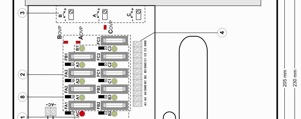
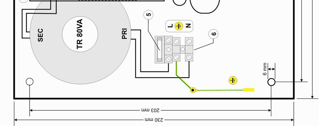
4 Fig.2. The view of the power-supply unit. 4
5 1.4. Technical parameters: - electrical parameters (tab.3) - mechanical parameters (tab.4) - operation safety (tab.5) - operation parameters (tab.6) Electrical parameters (tab. 3). Supply voltage 230V AC (-15%/+10%) Supply frequency 50Hz (47 53Hz) PSU module power P 36W max. Current consumption 0.5A/230V Output voltage 12,0V DC nom. Output voltage setting, escalation and keeping 55ms/50ms/12ms time Voltage setting range 11,0V 15,0VDC (-/+5%), 3x adjustment A, B, C Output current 9x 0,33A for fuses F 500mA, ΣI= 3,0A max (total, uninterrupted) Short-circuit protection SCP 9x F 500mA fuses (damage, fuse-element replacement required) or PTC 500mA - set by jumper Short-circuit protection OLP 110% 150% power supply power, limitation for three sections by PTC fuses, reset requires turn off the supply or load for about 1 min. Overvoltage protection OVP 17V (-/+ 5%) Surge protection varistors TAMPER output indicating the opening of the power supply casing - micro-switch x2, NC contacts (closed casing, mounted on foundation), 0.5A@50V DC (max) Optical indication: diodes 1 5 (green) diode AC (red) diodes AOVP, BOVP, COVP (red) (on unit PCB) Fuse F Bezpiecznik FA1 FC3 - outputs status A1, A2, A3, B1, B2, B3, C1,C2, C3 normal status = lights failure status= does not light - supply status AC: normal status = lights failure status= does not light - OVP overvoltage protection status: normal status = lights failure status= does not light T 1A/250V F 500mA/ 250V Mechanical parameters (tab. 4). Casing dimensions 235 x 235 x 98 (230 x 230 x 90) (WxHxD) Fixation 205 x 203 x Φ 6 WxH Net/gross weight 3,2/3,4 kg Casing color RAL 9003 Closing Cheese screw: at the front of the casing Connectors Supply 230V AC: Φ0,63-2,05 (AWG 22-12) DC outputs: Φ0,51-2,05 (AWG 24-12) Notes The casing is distant from the assembly surface so that cables can be installed convection cooling Operation safety (tab.5). Protection class PN-EN :2004 I (first) Protection grade PN-EN 60529: 2002 (U) IP20 Electrical strength of insulation: - between input (network) circuit and output circuits of power-supply (I/P-O/P) 3000 V/AC min. - between input circuit and PE protection circuit (I/P-FG) 1500 V/AC min. - between output circuit and PE protection circuit (O/P-FG) 500 V/AC min. Insulation resistance: - between input circuit and output or protection circuit 100 MΩ, 500V/DC Operation parameters (tab.6). Operation temperature Storage temperature Relative humidity Vibrations during operation Impulse waves during operation Direct isolation Vibrations and impulse waves during transport -10ºC...+40ºC +5ºC...+40ºC 30%...90%, without condensation Unacceptable Unacceptable Unacceptable According to PN-83/T
6 2. Installation. 2.1 Requirements. The buffer power-supply shall be mounted by the qualified installer having appropriate (required and necessary for a given country) permissions and qualifications for connecting (operating) 230V AC installations and low-voltage installations. The device shall be mounted in closed rooms, according to the environment class II, of the normal air humidity (RH=90% max. without condensation) and the temperature within the range from -10 C to +40 C. The powersupply shall operate in a vertical position so that free and convectional air flow through ventilating holes of the casing is guaranteed. Before installation is started, the balance of the power-supply load shall be performed. During the normal operation, the sum of currents collected by receivers shall not exceed I=3A (P=36W max.). It is acceptable to change values of fuses to other than original, if not all outputs of power supply are used and Pmax is not exceeded. As the power-supply is designed for a continuous operation and is not equipped with a power-switch, therefore an appropriate overload protection in the power supply circuit shall be guaranteed. Moreover, the user shall be informed about the method of isolation of the power supply from the power voltage (usually through assignment and marking of an appropriate fuse in the fuse-box). The electrical system shall be made in accordance with valid standards and regulations. 2.2 Installation procedure. 1. Before installation is started, the voltage in the 230V power-supply circuit shall be isolated. 2. The power-supply shall be mounted in a selected location and connection cords shall be lead. 3. Remove the power fuse protecting the power supply circuit. 4. The power cables (~230V AC) shall be connected to L-N terminals of the power supply. The earth conductor shall be connected to the terminal marked by the earth symbol. The connection shall be made by means of a three-core cable (with a yellow and green PE protection wire). The power cables shall be lead to appropriate terminals of the connection board through bushing. The circuit of the shock protection shall be performed with a particular care, i.e. the yellow and green protection wire of the power cable shall be connected from one side to the terminal marked by the symbol of in the casing of the power-supply. Operation of the power-supply without the properly made and fully operational circuit of the shock protection is UNACCEPTABLE!. It can result in failure of devices and electric shock. 5. Connect the conductors of consumers to: A1, A2, A3, B1, B2, B3, C1, C2, C3 and GND x3 (maintaining polarization). 6. As there are significant voltage drops at the resistance of power cables of receivers during installation, it is possible to adjust a voltage value by potentiometer A - outputs A1, A2, A3 B - outputs B1, B2, B3 C - outputs C1, C2, C3 7. Insert the fuse into the power supply circuit and switch on power. 8. Check the optical signaling of the power supply. 9. After installation is completed and operation of the power-supply is checked, the casing can be closed. 3. The power supply unit operation indication. The power-supply is equipped with the optical signaling of operation modes. Voltage at the outputs of the power supply is indicated by lighting of green LEDs at the front panel of the device. 3.1 Optical signaling (fig.3.). Green LEDs A1.C3 indicate the power-supply mode at outputs: A1..C3 If power supply is lost at the output (fuse blow), a correspondent LED stops lighting (A1 for A1 output, etc.) The red LED AC indicates supply status at power supply unit input. In case of supply loss at input (lack of 230V AC, F failure) the diode stops lighting. 6
. Fig.3. The view of LED panel. 4.")
7 Red LED s AOVP, BOVP, COVP (on unit PCB) indicates overvoltage protection status for a particular group: A, B, C. In case of protection activation, a correspondent LED lights (AOVP the group of A outputs etc.). Fig.3. The view of LED panel. 4. Service and operation. 4.1 Procedure in case of short-circuit (activation of SCP) of the power supply output. Outputs of the O1 O9 power supply are protected against short-circuits with fuse-element safety device (inserts) or PTC. In case of damaging fuse-element safety device it is necessary to exchange the fuse (compliant with the original). If PTC polymer fuses protection was chosen, then automatic disconnection of the output voltage was signalled by switching off the green diode. It is then necessary to disconnect the load from the power supply output for the period of about 1 min. It is acceptable to change values of fuses to other than original, if not all outputs of power supply are used and Pmax is not exceeded. 4.2 Procedure in case of overload (activation of OLP) of the power supply output. Sections A, B, C are equipped with the PTC protection based on polymer fuses. In case of overload of section with the current which exceeds value 1,6A, the overloaded section will be automatically disconnected. It is signalized by turnig off LED s of overloaded section. Return of output voltage require turning off the overloaded section or 230V AC supply for about 1 minute time. 4.3 Maintenance. All maintenance operations can be performed after the power supply is disconnected from the power network. As for the power supply, it is not necessary to perform any special maintenance operations, but if the power supply interior is significantly dusty, it shall be vacum-cleaned by compressed air. In case of fuse replacement, the spare parts shall be the same as original ones. 7
8 WEEE MARK The waste electric and electronic products do not mix with general household waste. There are separate collection system for used electric and electronic products in accordance with legislation under the WEEE Directive and is effective only with EU. GENERAL WARRANTY CONDITIONS 1. Pulsar K. Bogusz Sp.j. (manufacturer) grants a two-year quality warranty for the equipment, starting from the date of purchase placed on the purchase order. 2. Should such purchase order be missing when the claim is submitted, the three-year guarantee period is counted from the date of the manufacturing of the device. 3. The warranty includes free-of-charge repairing or replacing with a functional equivalent (the selection is made by the manufacturer) of the malfunctioning device, due to reasons attributable to the manufacturer, including manufacturing and material defects, unless such defects have been reported beyond the warranty period (item 1 and 2). 4. The equipment subject to warranty is to be brought to the place where it was purchased, or directly to the main office of the manufacturer. 5. The warranty applies to complete equipment, including the type of defect specified in writing, using a properly filled warranty claim. 6. Should the claim be accepted, the manufacturer is obliged to render warranty repairs, as soon as possible, however not later that within 14 days from the delivering of the equipment to the service centre of the manufacturer. 7. The repair period mentioned in item 5 may be prolonged, if there is no technical capability to carry out the repairs, and in the case that the equipment has been accepted conditionally, due to the failing of the warranty terms by the claimant. 8. All the services rendered by force of the warranty are carried out at the service centre of the manufacturer, exclusively. 9. The warranty does not cover the defects of the equipment, resulting from: - reasons beyond the manufacturer's control, - mechanical damage, - improper storage and transport, - use that violates the operation manual or equipment application, - random events, including lightning discharges, failures of power networks, fire, flooding, high temperatures and chemical agents, - improper installation and configuration (at variance with the rules set forth in the manual), 10. Each confirmation of structural modifications or repairs, carried out beyond the service centre of the manufacturer, or any modification of serial numbers or warranty labels, results in the loss of the rights resulting from the warranty. 11. The liability of the manufacturer towards the buyer is limited to the value of the equipment, determined according to the wholesale prices suggested by the manufacturer on the day of purchase. 12. The manufacturer shall not be responsible for the defects that resulted from the damaging, malfunctioning or inability to operate the equipment, particularly, if such defects are the result of failing to abide by the recommendations and requirements contained in the manual, or the use of the equipment. Pulsar K.Bogusz Sp.j. Siedlec 150, Łapczyca, Poland Tel. (+48) , Fax. (+48) biuro@pulsar.pl, sales@pulsar.pl 8
PSU-S-12V/L-1A/5/FTA/PTC-TR-MC AWZ v.1.0
 PSU-S-12V/L-1A/5/FTA/PTC-TR-MC AWZ 05121 v.1.0 Linear, stabilized power supply unit. Edition: 1 from the 2 nd February 2011 Supercedes edition: Features of the power supply unit: five outputs protected
AWZ 200. AWZ 13,8V/2A/7Ah/L
 GREY POWER AWZ 200 v.2.4 AWZ 13,8V/2A/7Ah/L Linear, Buffer Power Supply Unit EN** Edition: 7 from 15.05.2014 Supercedes the edition: 6 from 13.02.2014 Features: 13,8VDC/2A uninterruptible supply fitting
HPSB 2512B v.1.0 HPSB 13,8V/2A/7Ah Buffer, switch mode power supply unit.
 HPSB 2512B v.1.0 HPSB 13,8V/2A/7Ah Buffer, switch mode power supply unit. EN* Edition: 5 from 05.06.2014 Supercedes the edition: 4 from 10.02.2014 Features: DC 13,8V/2A uninterruptible power supply* fitting
POE1824B. PoE 27,6V/4x0,4A/2x7Ah/PoE
 v.1.0 PoE 27,6V/4x0,4A/2x7Ah/PoE Buffer switch mode power supply unit EN* Edition: 2 from 16.09.2013 Supercedes the edition: 1 from 06.02.2012 Features: DC 27,6 V/4x0,4A uninterruptible power supply fitting
BNC BNC 12V/8x1A. Switch mode power supply unit for CCTV. v.1.0 EN** Edition: 1 from Supersedes the edition:
 BNC08128 v.1.0 BNC 12V/8x1A Switch mode power supply unit for CCTV. EN** Edition: 1 from 26.11.2013 Supersedes the edition: ------ GREEN POWER CCTV BNC PSU features: supply output 8x1A/12V DC output voltage
BNC08128C. BNC 13,8V/8x1A/17Ah. Switch mode buffer power supply unit for CCTV. v.1.0 EN** Edition: 1 from Supersedes the edition:
 BNC08128C v.1.0 BNC 13,8V/8x1A/17Ah Switch mode buffer power supply unit for CCTV. EN** Edition: 1 from 26.11.2013 Supersedes the edition: ------ GREEN POWER CCTV BNC PSU features: DC 13,8V/8x1A uninterruptible
PSDCB161220E. v.1.0. PSDCB 13,8V/20A/16x1A/65Ah. Buffer power supply for up to 16 HD cameras. EN** Edition: 3 from
 PSDCB161220E v.1.0 PSDCB 13,8V/20A/16x1A/65Ah Buffer power supply for up to 16 HD cameras. EN** Edition: 3 from 15.11.2017 Supercedes the edition: 2 from 24.04.2017 GREEN POWER CCTV Features: DC 13,8V/20A
AWZ 110. AWZ 13,8V/1A/7Ah/LM
 AWZ 110 v.1.3 AWZ 13,8V/1A/7Ah/LM Linear buffer power supply unit Grade 2. EN* Edition: 9 from 02.11.2017 Supercedes the edition: 8 from 23.01.2017 GREY POWER plus Features: EN50131-6 compliance, 1 2 grades
PSBSH 2012B. PSBSH 13,8V/2A/7Ah/HERMETIC
 PSBSH 2012B v.1.2 PSBSH 13,8V/2A/7Ah/HERMETIC Buffer switch mode power supply unit, EN** Edition: 7 from 02.11.2017 Supercedes the edition: 6 from 08.06.2017 Features: DC 13,8V/2A uninterruptible power
PSUPS10A12C. PSUPS 13,8V/12V/10A/17Ah. Buffer power supply for 8 HD cameras and recorder. v.1.0. Supercedes the edition: 1 from
 v.1.0 PSUPS 13,8V/12V/10A/17Ah Buffer power supply for 8 HD cameras and recorder EN Edition: 2 from 15.11.2017 Supercedes the edition: 1 from 23.05.2017 GREEN POWER CCTV Features: DC 13,8V uninterruptible
FIREMAN'S MICROPHONE POWER SUPPLY FOR THE VOICE ALARM SYSTEMS 24V
 DSOS24V v.1.0 FIREMAN'S MICROPHONE POWER SUPPLY FOR THE VOICE ALARM SYSTEMS 24V EN* Edition: 2 from 30.08.2017 Supercedes edition: 1 from 24.05.2016 PSU features. Compliant with the requirements of the
Dycon D1532SM. EN50131/PD6662 Grade 3, 12V 2A Power Supply. Technical Description Installation and Operating Manual DYCON POWER SOLUTIONS LTD
 Dycon D1532SM EN50131/PD6662 Grade 3, 12V 2A Power Supply Technical Description Installation and Operating Manual DYCON POWER SOLUTIONS LTD Tel: +44 (0)1443 471 900 Unit A Cwm Cynon Business Park Mountain
LS200 Series Instruction Manual
 LS200 Series Instruction Manual BEFORE USING THE POWER SUPPLY UNIT Pay attention to all warnings and cautions before using the unit. Incorrect usage may lead to an electrical shock, damage to the unit
CIRCUIT-TEST OPERATION MANUAL. Switching Mode Power Supply with Remote Sensing PSC V 5A / 0-27V 3A / 0-36V 2.2A (80W)
") CIRCUIT-TEST Switching Mode Power Supply with Remote Sensing PSC-9800 0-16V 5A / 0-27V 3A / 0-36V 2.2A (80W) OPERATION MANUAL 1 2 PSC-9800 08R14 Contents Safety Precautions...page 4 Introduction... 5 Controls
CIRCUIT-TEST Switching Mode Power Supply with Remote Sensing PSC-9800 0-16V 5A / 0-27V 3A / 0-36V 2.2A (80W) OPERATION MANUAL 1 2 PSC-9800 08R14 Contents Safety Precautions...page 4 Introduction... 5 Controls
Features. Description. Table of Contents
 Features Very low profile Very high efficiency (typically 90%) Single and dual output versions Input voltages from 24V to 110VDC nominal voltages from 5V to 48VDC -40 C to +71 C operation without de-rating
Module B Module C FOR THE WEATHER CONTROLLER MULTI-MIX INSTALLATION MANUAL REVISION: 1.0_EN
 Module B Module C FOR THE WEATHER CONTROLLER MULTI-MIX INSTALLATION MANUAL REVISION: 1.0_EN 05-2018 ELECTRIC DEVICE UNDER VOLTAGE! Before any action related to the power supply (cables connection, device
Power supply unit PS-303
 Power supply unit PS-303 Technical Documentation (303-4-04022011) St. Petersburg 2011 Table of Contents 1. GENERAL INFORMATION...3 2. DELIVERY SET...3 3. TECHNICAL DATA...3 4. DESCRIPTION AND FUNCTIONALITY
Dycon D2430 EN54-4 Fire Alarm Power Supply Series
 Dycon D2430 EN54-4 Fire Alarm Power Supply Series Technical Description Installation and Operating Manual Construction Product Regulation 0359-CPR-00434 Page 1 of 14 Contents 1. General... 3 1.1 Product
Uninterruptible power supply Supply MEg101.4
 Uninterruptible power supply Supply MEg101.4 MEgA Měřící Energetické Aparáty, a.s. 664 31 Česká 390 Czech Republic Uninterruptible power supply Supply MEg101.4 Uninterruptible power supply MEg101.4 1/
Features. LED Driver. RACT09 9 Watt. TRIAC Dimmable. Single Output RACT09- AC/DC Converter
 Features TRIAC Dimmable LED Driver Triac dimmable with leading or trailing edge dimmers Class II with SELV output (no earth required) Extra-large screw terminals and integrated cable clamps for easy installation
Model 1900, 1901, 1902 Switching DC Power Supply
 Model 1900, 1901, 1902 Switching DC Power Supply INSTRUCTION MANUAL 1 Safety Summary The following safety precautions apply to both operating and maintenance personnel and must be observed during all
OWNER S MANUAL Please read this manual before operating your power supply
 AC-DC POWER SUPPLY Switch Mode AC-DC Power Supply Model No. PSU-1210 PSU-1223 PSU-1230 OWNER S MANUAL Please read this manual before operating your power supply Table of Contents Precautions 2 Description
USER MANUAL. 10 January Certification of constancy of performance CNBOP No CPR-0454 Certificate of admittance CNBOP No.
 User Manual ZSP100 Document No. 0658.00.95-03.2 Page 1/6 MERAWEX Sp. z o.o. Toruńska 8 44-122 Gliwice Poland tel. +48 32 23 99 400 fax +48 32 23 99 409 merawex@merawex.com.pl http://www.merawex.com.pl
HYGRODYNAMICS DIGITAL DEW POINT MONITOR PC BOARD MODEL 6392N & 6392N2 TABLE OF CONTENTS
 HYGRODYNAMICS DIGITAL DEW POINT MONITOR PC BOARD MODEL 6392N & 6392N2 TABLE OF CONTENTS INTRODUCTION... 2 SPECIFICATIONS... 2 INSTALLATION... 3 PC Board Mounting...3 Sensor Installation...3 Manifold Assembly...4
PSU EN54-4 Power Supplies
 PSU EN54-4 Power Supplies Ordering: Models, Sales Order Parts: PSU MXP-549 : 1.5A PSE in 7Ah enclosure MXP-550 : 3.0A PSE in 17/18Ah enclosure MXP-550D : 3.0A PSE in 25Ah enclosure MXP-551 : 5.0A PSE in
Model 1900, 1901, 1902 Switching DC Power Supply
 Model 1900, 1901, 1902 Switching DC Power Supply INSTRUCTION MANUAL 1 Safety Summary The following safety precautions apply to both operating and maintenance personnel and must be observed during all
99 Washington Street Melrose, MA Fax TestEquipmentDepot.com. Instruction Manual. Model 1672 Triple Output Power Supply
 99 Washington Street Melrose, MA 02176 Fax 781-665-0780 TestEquipmentDepot.com Instruction Manual Model 1672 Triple Output Power Supply Contents Section Description Page No. CONTENTS 1 1 TEST INSTRUMENT
Mini Multimeter with Non-Contact Voltage Detector (NCV)
") Owner s Manual Mini Multimeter with Non-Contact Voltage Detector (NCV) Model No. 82314 CAUTION: Read, understand and follow Safety Rules and Operating Instructions in this manual before using this product.
Owner s Manual Mini Multimeter with Non-Contact Voltage Detector (NCV) Model No. 82314 CAUTION: Read, understand and follow Safety Rules and Operating Instructions in this manual before using this product.
GE FANUC Parts. VersaPoint Power Terminal. Segment Terminal Fused, with Diagnostics 24VDC IC220PWR013. Features. Ordering Information
 Segment Terminal Fused, with Diagnostics 24VDC Segment Terminal module is used to create a protected partial circuit (segment circuit) within the main circuit. It is not used to supply power and has no
SYMBOL LEGEND DANGER WARNING NOTE THIS INDICATES DANGER TO THE LIFE AND HEALTH OF THE USER IS APPROPRIATE PRECAUTIONS ARE NOT TAKEN
 SYMBOL LEGEND DANGER THIS INDICATES DANGER TO THE LIFE AND HEALTH OF THE USER IS APPROPRIATE PRECAUTIONS ARE NOT TAKEN WARNING THIS WARNS THAT MATERIALS MAY BE DAMAGED IF APPROPRIATE PRECAUTIONS ARE NOT
Switching DC Power Supply
 99 Washington Street Melrose, MA 02176 Phone 781-665-1400 Toll Free 1-800-517-8431 Visit us at www.testequipmentdepot.com Model 1693, 1694 Switching DC Power Supply INSTRUCTION MANUAL 1 Safety Summary
EVS RP6020. Instruction Manual
 Instruction Manual TDK Lambda BEFORE USING THE PRODUCT Be sure to read this instruction manual thoroughly before using this product. Pay attention to all cautions and warnings before using this product.
Aurora Wind Interface Box
 Aurora Wind Interface Box Installation and Operator s Manual Page 2 of 15 REVISION TABLE Document Revision Author Date Change Description 1.0 T. Melzl 5/9/2006 First release of the document SAVE THESE
ACC Series Power Conditioner OPERATION & INSTALLATION MANUAL
 ACC Series Power Conditioner OPERATION & INSTALLATION MANUAL PHASETEC digital power conditioners are designed to safely operate electrical equipment in the harshest power quality environments. With a wide
Pure Sine Wave Inverter 600W-24V User Manual
 Pure Sine Wave Inverter 600W-24V User Manual Manual Version:INV-600W-2016-1 Table of Contents 1. INTRODUCTION... 1 1.1 General Description... 1 1.2 Key Features... 2 2. SAFETY INSTRUCTIONS... 2 2.1 Installation
Operating manual UPS - System
 Operating manual UPS - System POWERMASTER M MIL 1000VA 7Min. BAX 3330 E UPS-Division Issued 15. August 2006 JOVYATLAS JOVYATLAS Elektrische Umformtechnik GmbH Groninger Straße 29-37 D-26789 Leer/Ostfriesland
INDUSTRIAL POWER SUPPLIES SFL-SERIES
 INDUSTRIAL POWER SUPPLIES SFL-SERIES Operating Instructions 1. Application The SFL-series are compact, rugged switching power supplies designed for applications in process automation and other industrial
Uninterruptible Power System
 USER'S MANUAL Emergency Backup Power Supply For Use With Computer Loads Only Power Surge/Noise Protection Intelligent Auto-Shutdown Software Internet Line Protection Cost Efficiency UPS 1 st Edition Uninterruptible
SSP-7080 USER MANUAL. 80W Constant Power Switching Mode Power Supply with Master & Slave Remote Sensing. Rev /
 SSP-7080 80W Constant Power Switching Mode Power Supply with Master & Slave Remote Sensing USER MANUAL Rev.1.1 2007/04 7673-7080-0000 CONTENTS Warning, Cautions and Operating Conditions P.1 Introduction
User Manual. Digital Energy Uninterruptible Power Supply ML Series UPS VA. GE Digital Energy Power Quality. GE imagination at work
 GE Digital Energy Power Quality User Manual Digital Energy Uninterruptible Power Supply ML Series UPS 350-500-700-1000 VA GE Consumer & Industrial SA General Electric Company CH 6595 Riazzino (Locarno)
CPS Energy Balancer. Version: 1.0
 CPS Energy Balancer Version: 1.0 CHINT POWER SYSTEMS AMERICA CO., LTD. Address: 700 International Parkway, Suite 102 Richardson, Texas Zip Code: 75081 Web: www.chintpower.com/na Email: americasales@chintpower.com
Sinewave Inverters. SWING pro 200VA and 350VA. User s manual
 Sinewave Inverters SWING pro 200VA and 350VA User s manual 1 Warranty RIPEnergy is not manufacturer of these units. All technical information s, data s and dimension s rely on information s given by the
Elmdene International Ltd
 1 Elmdene International Ltd Tel: +44(0)23 9269 6638 3 Keel Close, Interchange Park, Fax: +44(0)23 9266 0483 Portsmouth, Hampshire, PO3 5QD, UK Web: www.elmdene.co.uk 13.8Vdc Switch Mode Power Supply GEN3-08-y
User Manual Digital Energy Uninterruptible Power Supply ML Series UPS VA GE Digital Energy Power Quality
 GE Digital Energy Power Quality User Manual Digital Energy Uninterruptible Power Supply ML Series UPS 350-500-700-1000 VA GE imagination at work GB User Manual Digital Energy Uninterruptible Power Supply
D R C- 4 0 s e r i e s
 LPS Bauart gepruft Sicherheit egelma ge od o s be wac g www. tuv.com ID 2000000000 Features Universal AC input / Full range Protections: Short circuit / Overload / Over voltage Battery low protection /
99 Washington Street Melrose, MA Fax TestEquipmentDepot.com. Instruction Manual. Model 2831D 4 ½ Digit True RMS Digital Multimeter
 99 Washington Street Melrose, MA 02176 Fax 781-665-0780 TestEquipmentDepot.com Instruction Manual Model 2831D 4 ½ Digit True RMS Digital Multimeter 1 1. PRODUCT DESCRIPTION 1-1. Introduction Thank you
STEPPER-BLOCKplus. Manual. Version: 2.0 As of: 06/2002 Author: Edmund Burger &RPSDFW6WHSSHU'ULYHU IRU3KDVH6WHSSLQJ0RWRUV. Main. Status-LED.
 Manual STEPPER-BLOCKplus &RPSDFW6WHSSHU'ULYHU IRU3KDVH6WHSSLQJ0RWRUV Main Status-LED Current Adjustment Controller Motor Version: 2.0 As of: 06/2002 Author: Edmund Burger All rights reserved: MOTRON Steuersysteme
FLÄKTGROUP PM-MOTOR WITH INTEGRATED FC 106 FREQUENCY CONVERTER
 FLÄKTGROUP PM-MOTOR WITH INTEGRATED FC 106 FREQUENCY CONVERTER INSTALLATION AND MAINTENANCE INSTRUCTIONS Risk of electric shock: Motor terminals may still be live if the impeller is rotating, even when
SecuriFire. Power Supply Unit B6-PSU. Technical Description. Securiton AG Alpenstrasse Zollikofen Switzerland
 SecuriFire Power Supply Unit B6-PSU Technical Description Securiton AG Alpenstrasse 20 3052 Zollikofen Switzerland T 811 039 en a Imprint Imprint Notice This document, T 811 039, is valid only for the
DC Master 24/ A
 USERS MANUAL DC Master 24/12 50-60A DC-DC converter MASTERVOLT Snijdersbergweg 93, 1105 AN Amsterdam The Netherlands Tel.: +31-20-3422100 Fax.: +31-20-6971006 www.mastervolt.com ENGLISH Copyright 2015
MODEL A96 SERIES. 130Vdc Switchmode Utility Rectifier / Battery Charger. Used with LaMarche Power Cage ECN/DATE
 MODEL A96 SERIES 130Vdc Switchmode Utility Rectifier / Battery Charger Used with LaMarche Power Cage CPN112138 ECN/DATE ISSUE DATE: ECN 17010-12/05 106 BRADROCK DRIVE DES PLAINES, IL. 60018-1967 (847)
ASTROAI USER MANUAL DIGITAL MULTIMETER. NOTE: Fully read and understand this manual before using this instrument.
 ASTROAI USER MANUAL DIGITAL MULTIMETER NOTE: Fully read and understand this manual before using this instrument. WARNING: To avoid possible electric shock or personal injury, and to avoid possible damage
miconverter 18-Module Rack-Mount Power Chassis User Manual 38 Tesla, Irvine, CA USA Phone: (949) ; Fax: (949) Page 12
 ; Fax: (949) Page 12") miconverter 18-Module Rack-Mount Power Chassis User Manual Page 12 38 Tesla, Irvine, CA 92618 USA Phone: (949) 250-6510; Fax: (949) 250-6514 General and Copyright Notice This publication is protected by
miconverter 18-Module Rack-Mount Power Chassis User Manual Page 12 38 Tesla, Irvine, CA 92618 USA Phone: (949) 250-6510; Fax: (949) 250-6514 General and Copyright Notice This publication is protected by
USE AND INSTALLATION HANDBOOK
 Date : 10/02/14 Rev. 01 PR.T : FG006172 USE AND INSTALLATION HANDBOOK DUPLEX-UP CONTROL PANEL FOR 2 ELECTRIC PUMPS WITH CURRENT CONTROL. DUPLEX-UP Via Enrico Fermi 8-35020 Polverara PD Tel.049/9772407
SYMBOL LEGEND DANGER WARNING NOTE THIS INDICATES DANGER TO THE LIFE AND HEALTH OF THE USER IS APPROPRIATE PRECAUTIONS ARE NOT TAKEN
 SYMBOL LEGEND DANGER THIS INDICATES DANGER TO THE LIFE AND HEALTH OF THE USER IS APPROPRIATE PRECAUTIONS ARE NOT TAKEN WARNING THIS WARNS THAT MATERIALS MAY BE DAMAGED IF APPROPRIATE PRECAUTIONS ARE NOT
Specifications 2019-V AC-DC Din Rail Mounted Power Supply IS-70 Series, 70W
 2019-V1.0-0318 Specifications AC-DC Din Rail Mounted Power Supply IS-70 Series, 70W No. 545 Museum Road Yangzhou, Jiangsu China 225009 Tel: 86 (514) 8279 1592 Fax: 86 (514) 8769 3159 2019 AC-DC Din Rail
DRB-1 Series Instruction Manual
 Instruction Manual BEFORE USING THE POWER SUPPLY UNIT Pay attention to all warnings and cautions before using the unit. Incorrect usage could lead to an electrical shock, damage to the unit or a fire hazard.
DP-153/DP-153-L Stepper Drive
 DP-153/DP-153-L Stepper Drive User Manual WUXI XINJE ELECTRIC CO., LTD. NO. DC05 20120210 1.0 Catalog 1. Summary... 1 1-1. Characteristic... 1 1-2. Application... 1 1-3. Electric characters... 1 2. Operation
DP-304/DP-304-L Stepper Drive
 DP-304/DP-304-L Stepper Drive User Manual WUXI XINJE ELECTRIC CO., LTD. NO. DC06 20111128 1.0 Catalog 1. Summary... 1 1-1. Characteristic... 1 1-2. Application... 1 1-3. Electric characters... 1 2. Operation
PRODUCTS: POWER SUPPLY
 PRODUCTS: POWER SUPPLY Impact Lighting Inc. All rights reserved. Impact Lighting Inc. Reserves the right to change specifications without notice. 138 POWER SUPPLY 15W AC-DC [12V/1.25A] UNIVERSAL POWER
2-PHASE STEPPING MOTOR DRIVER FE Z5 DISPENSE
 2-PHASE STEPPING MOTOR DRIVER FE Z5 DISPENSE For Diaphragm Dosing Pumps FEM 1.02_.55 / FEM 1.09_.55 Controller board package, without pump: ID 160536 Operating and Installation Manual It is important to
Models. Output current max.* Output Power max. Low Line : VAC High Line: VAC 24 VDC / 12 A 240 W. Back up battery
 AC/DC Battery Controller Power Supply TSPC-240UPS Series Compact universal 24 VDC power supply with integrated battery controller module Battery protection for over voltage, deep discharge, short circuit
Autoranging Industrial Multimeter
 Owner's Manual Autoranging Industrial Multimeter Model No. 82005 CAUTION: Read, understand and follow Safety Rules and Operating Instructions in this manual before using this product. Safety Operation
AC/DC Converter MBP250-2A13D13M
 250W, 165-264VAC Input, Dual output AC/DC battery charging module power supply FEATURES Low stand-by power consumption, Maximum instantaneous power up to 350W With charging function, the 12V output Lead-acid
IB IL 24 PWR IN/F-D IB IL 24 PWR IN/F-D-PAC
 IB IL 24 PWR IN/F-D IB IL 24 PWR IN/F-D-PAC Inline Power Terminal With Fuse and Diagnostics Data Sheet 5569C 02/2003 # # $ ' ) The IB IL 24 PWR IN/F-D and IB IL 24 PWR IN/F-D-PAC only differ in the scope
LC BATTERY CHARGER OPERATION & MAINTENANCE GUIDE
 LC BATTERY CHARGER OPERATION & MAINTENANCE GUIDE SENS part number: 101194 Document revision: D DCN number: 105128 Date: 3/23/2006 1840 Industrial Circle Longmont, CO 80501 Fax: 303-678-7504 Tel: 303-678-7500
Advanced Battery Charger 0 ~ 15A 0 ~ 25A 0 ~ 35A 0 ~ 50A 0 ~ 80A. 3 - stage charging capability (IUOU) 90 ~ 264VAC (refer to de-rating curve)
 90 ~ 264VAC (refer to de-rating curve)") Cxx Features: Universal AC input with active PFC Compatible with Lead Acid, Li-ion, Gel and AGM batteries Support optional remote controller (CR-) Voltage / temperature compensation with battery temp.
Cxx Features: Universal AC input with active PFC Compatible with Lead Acid, Li-ion, Gel and AGM batteries Support optional remote controller (CR-) Voltage / temperature compensation with battery temp.
Fuse state indicator MEg72. User manual
 Fuse state indicator MEg72 User manual MEg Měřící Energetické paráty, a.s. 664 31 Česká 390 Czech Republic Fuse state indicator MEg72 User manual Fuse state indicator MEg72 INTRODUCTION The fuse state
Model 1693, 1694 Switching DC Power Supply
 Model 1693, 1694 Switching DC Power Supply INSTRUCTION MANUAL 1 Safety Summary The following safety precautions apply to both operating and maintenance personnel and must be observed during all phases
Electronic Circuit Breaker ESS20-0..
 Electronic Circuit Breaker ES-0.. Description Electronic circuit breaker type ES-0.. is designed to ensure selective disconnection of individual loads in systems which are powered by a DC 4 V switch-mode
UCS-CHR24V55W. Combined Power Supply & Battery Charger. Data Sheet
 Combined Power Supply & Battery Charger Data Sheet INTRODUCTION UCS-CHR24V55W is a combined charger and power supply with dedicated outputs for both charging and power supply. With a large input range
WELDING INVERTER. PEGAS 160 E Smart PEGAS 200 E Smart OPERATING MANUAL. ALFA IN a.s. PEGAS E Smart Manual EN 04
 WELDING INVERTER PEGAS 160 E Smart PEGAS 200 E Smart OPERATING MANUAL PEGAS 160-200 E Smart Manual EN 04 2/12 CONTENT: 1. INTRODUCTION... 3 2. SAFETY INSTRUCTIONS AND WARNINGS... 4 3. TECHNICAL DATA...
True RMS Autoranging Multimeter
 Owner's Manual True RMS Autoranging Multimeter Model No. 73754 CAUTION: Read, understand and follow Safety Rules and Operating Instructions in this manual before using this product. Safety Operation Maintenance
Video & Power Over Coax Kit
 VPoC User Manual Video & Power Over Coax Kit 1CH Video Power over Coax w/ 12V DC Receiver Device VPoC24DC-01K VPoC24DC-01 N-42-1 x1 N-41C 4CH / 8CH / 16CH Video Power over Coax Server Kit VPoC24DC-04K
90W DC Power Supply. User Manual. 99 Washington Street Melrose, MA Phone Toll Free
 99 Washington Street Melrose, MA 02176 Phone 781-665-1400 Toll Free 1-800-517-8431 Visit us at www.testequipmentdepot.com 1410 90W DC Power Supply User Manual Safety Summary The following safety precautions
WARNING. This product uses High Brightness LEDs. Direct viewing of the SMD LEDs at close range should be avoided. Keep product away from children.
 WARNING Before use please remove the LED Tape from its bag and allow the odour to dissipate in an unused room or outdoor building. Wash Hands after handling. This product uses High Brightness LEDs. Direct
Specifications 2019-V AC-DC Din Rail Mounted Power Supply IS-480 Series, 480W
 2019-V1.0-0118 Specifications AC-DC Din Rail Mounted Power Supply IS-480 Series, 480W No. 545 Museum Road Yangzhou, Jiangsu China 225009 Tel: 86 (514) 8279 1592 Fax: 86 (514) 8769 3159 2019 AC-DC Din Rail
Autoranging Multimeter
 Owner's Manual Autoranging Multimeter Model No. 82334 CAUTION: Read, understand and follow Safety Rules and Operating Instructions in this manual before using this product. Safety Operation Maintenance
IB IL 24 SEG/F. Function. INTERBUS Inline Segment Terminal With Fuse. Data Sheet 5656B
 INTERBUS Inline Segment Terminal With Fuse Data Sheet 5656B 02/2001 # $ # $ ) This data sheet is intended to be used in conjunction with the Configuring and Installing the INTERBUS Inline Product Range
& HIGH CURRENT DC POWER SUPPLIES INSTRUCTION MANUAL
 72-6850 & 72-6852 HIGH CURRENT DC POWER SUPPLIES INSTRUCTION MANUAL Table of Contents Introduction 2 Specification 2 Safety 4 EMC 5 Installation 6 Connections 6 Operation 7 Maintenance and Repair 8 www.tenma.com
SBC V In-Car Charger Dual Input (Solar MPPT & DC)
") SBC-5926 12V In-Car Charger Dual Input (Solar MPPT & DC) Operation manual Keep this manual in a safe place for quick reference at all times. This manual contains important safety and operation instructions
SBC-5926 12V In-Car Charger Dual Input (Solar MPPT & DC) Operation manual Keep this manual in a safe place for quick reference at all times. This manual contains important safety and operation instructions
n Operator s Manual n Redundant Control Unit FOR CFR UNINTERRUPTIBLE POWER SUPPLIES FROM ALPHA TECHNOLOGIES
 n Operator s Manual n Redundant Control Unit FOR CFR UNINTERRUPTIBLE POWER SUPPLIES FROM ALPHA TECHNOLOGIES TABLE OF CONTENTS 1. Introduction...1 1.1 The Alpha Redundant Control Unit (RCU)... 1 1.2 A Tour
27.6 Vdc 1 Amp Switch Mode Power Supply for Fire EN54-4:1997 +A1 +A2
 1 27.6 Vdc 1 Amp Switch Mode Power Supply for Fire EN54-4:1997 +A1 +A2 STX2401-C STX2401-T FEATURES 0843-CPR-0213 14 Elmdene International Ltd Tel: +44(0)23 9269 6638 3 Keel Close, Interchange Park, Fax:
SAFETY- FLY 700 P USER MANUAL FLYING INSTRUMENT FOR ULTRALIGHT AIRCRAFTS NR MIT
 SAFETY- FLY 700 P FLYING INSTRUMENT FOR ULTRALIGHT AIRCRAFTS NR.1017.2 MIT USER MANUAL UK Manufacturer Preface : MC elettronica S.r.l. Address : Via E. fermi, 450/486 Fiesso Umbertiano (ROVIGO) - ITALY
Sinewave Inverters. SWING 150VA and 300VA. User s manual
 Sinewave Inverters SWING 150VA and 300VA User s manual 1 Warranty RIPEnergy is not manufacturer of these units. All technical information s, data s and dimension s rely on information s given by the manufacturer.
BRAVO Inverter/Battery Charger. Table of Contents
 BRAVO 1050 Inverter/Battery Charger Table of Contents Introduction... 2 General Description... 2 Specifications... 3 Installation: Hardwire Units... 4 Operation: Hardwire Units... 5-6 Installation: GFCI
The 4HR-UPS 220V ac output is provided via a Pure Sine Wave inverter, allowing it to be backed up by 2x 12V standby batteries.
 1 Elmdene International Ltd Tel: +44 (0)23 9269 6638 3 Keel Close, Interchange Park, Fax: +44 (0)23 9266 0483 Portsmouth, Hampshire, PO3 5QD, UK Web: www.elmdene.co.uk STANDBY 220V AC POWER SYSTEM IDEAL
EPS/ELA-Series User Manual EPS/ELA 250W
 EPS/ELA-Series User Manual EPS/ELA 250W EPS Stromversorgung GmbH Tel: +49 (0)821 570451 0 Index 3 Page: 1 Table of contents: Page 1. Features of ELA-Series... 3 1.1 Basic Functions... 3 1.2 Options...
The Power of Reliability INSTRUCTION MANUAL
 The Power of Reliability INSTRUCTION MANUAL SAFETY & WARNINGS Read this manual carefully and understand all Warnings and Cautions before connections are made to the Inverter. If unsure about any aspects
INSTALLATION INSTRUCTIONS FOR Owner's Copy FILTERED AND REGULATED POWER SUPPLY VOLTS DC INPUT: Hz.
 103158 March 9, 2011 FOR INDOOR USE ONLY Detex Corporation, 302 Detex Drive, New Braunfels, Texas 78130-3045 (830)629-2900 / 1-800-729-3839 / Fax (830)620-6711 E-MAIL: detex@detex.com INTERNET: www.detex.com
Installation Instructions & Users Manual
 Installation Instructions & Users Manual UTILITY/ BUILDING INPUT 120 VAC ( OPTION) 15-20A N L CONTROL BOARD G SECURITY LIGHTING POWER SUPPLY (OPTION) CHARGER- POWER SUPPLY ASSBY XFMR (OPTION) CBM MODEL
Angle sensor AN2 series 30
 Angle sensor AN2 series 30 RE 95143 Edition: 09.2016 Replaces: 06.2015 Hall-effect sensor for angular measurement Features Angle sensor element based on the Hall-effect principle Shaft can be turned through
PURE SINE WAVE DC TO AC POWER INVERTER
 PURE SINE WAVE DC TO AC POWER INVERTER 60S-12A / 60S-24A 60S-12E / 60S-24E 100S-12A / 100S-24A 100S-12E / 100S-24E 150S-12A / 150S-24A 150S-12E / 150S-24E Instruction manual SINE WAVE INVERTER Please read
Angle Sensor WS1. RE Edition: Replaces:
 Angle Sensor WS1 RE 95140 Edition: 06.2017 Replaces: 07.2007 Hall-effect semiconductor elements and integrated amplifiers Robust plastic housing with moulded plug Metal inner housing and line filter for
OWNERS MANUAL JANUARY 2007 ISO
 Manufacturer of Dimensions TM Inverters 4467 White Bear Parkway St. Paul, MN 55110 Phone: 651-653-7000 Fax: 651-653-7600 E-mail: inverterinfo@sensata.com Web: www.dimensions.sensata.com 121231B OWNERS
TABLE OF CONTENTS. 8.3 Online Sensor Specifications. Series TS (Models TS1, TSP, TSH, TSL,TSF, TSB1, TSB2) According to Electromatic factory procedure
 According to Electromatic factory procedure") 8.3 Online Sensor Specifications Series TS (Models TS1, TSP, TSH, TSL,TSF, TSB1, TSB2) Calibration: Accuracy: Remainder of range and other calibration material Overload protection Measuring principle Measuring
8.3 Online Sensor Specifications Series TS (Models TS1, TSP, TSH, TSL,TSF, TSB1, TSB2) Calibration: Accuracy: Remainder of range and other calibration material Overload protection Measuring principle Measuring
IGLOO IGLOO EASY INSTRUCTION MANUAL
 ENGLISH EASY C695 C698 INSTRUCTION MANUAL Congratulations on choosing a Clay Paky product! We thank you for your custom. Please note that this product, as all the others in the rich Clay Paky range, has
ADI-125/750 ADI-125/1500 ADI-125/2500
 Manufacturer of Dimensions TM Inverters 4467 White Bear Parkway St. Paul, MN 55110 Phone: 651-653-7000 Fax: 651-653-7600 E-mail: inverterinfo@sensata.com Web: www.dimensions.sensata.com 121094B OWNERS
Art. No. EC-315. Art. No. EC-330. Art. No. EC-340 SWITCH-MODE BATTTERY CHARGER CONTENTS IMPORTANT SAFETY PRECAUTIONS... 2
 SWITCH-MODE BATTTERY CHARGER CONTENTS IMPORTANT SAFETY PRECAUTIONS... 2 DESCRIPTION AND FEATURES... 3 CHARGING STAGES... 4 Art. No. EC-315 Art. No. EC-330 Art. No. EC-340 PROTECTIONS... 5 INSTALLATION...
Filterpack FR-BFP2-(H)0.4K to (H)15K
0.4K to (H)15K") INVERTER INSTRUCTION MANUAL FR-BFP2-(H)0.4K to (H)15K 1. Product Checking... 1 2. Applicable Inverter... 1 3. Installation... 2 3.1 Inverter Installation (installation of the )...2 4. Wiring... 4 5. Main
INVERTER INSTRUCTION MANUAL FR-BFP2-(H)0.4K to (H)15K 1. Product Checking... 1 2. Applicable Inverter... 1 3. Installation... 2 3.1 Inverter Installation (installation of the )...2 4. Wiring... 4 5. Main