CCS-100 Cruise Control Installation: 2000 Road Star. December 2, By Scott Anderson. Introduction
|
|
|
- Dorcas Franklin
- 6 years ago
- Views:
Transcription
1 CCS-100 Cruise Control Installation: 2000 Road Star December 2, 2010 By Scott Anderson Introduction The following is a summary of the information required to install a CCS-100 cruise control system on a 2000 Yamaha Road Star. This information is provided for reference only, and is not intended to replace the CCS-100 Installation Manual. If installing this system on another model year Road Star, consult the appropriate Yamaha Road Star service manual and verify all electrical connections. This document is not intended to be a training course on how to install automotive cruise controls on motorcycles. It is intended to be a supplement to the CCS-100 Installation Manual, for those persons that choose to install the CCS-100 cruise control system on their motorcycle. Persons using this document, or any part thereof, must accept full responsibility for their own actions in regard to the installation, and subsequent operation of the motorcycle with the installed cruise control system. In providing this information, I am assuming the reader is technically competent to do an installation such as this, and has a basic understanding of the Yamaha Road Star; such as removing the fuel tank, 12V wiring, etc. It will be necessary for the installer to fabricate (or purchase from Murphs') a bracket for the keypad, mount the servo unit, mount the vacuum canister, make electrical connections, as well as throttle and vacuum connections. I suggest you read this entire document, and become thoroughly familiar with the manual before you proceed. Once you know what you need to do, the CCS-100 is not that difficult to install. Everything that follows is based on the installation I did on my 2000 Road Star. I spent a lot of time just looking at different ways to mount the components, and the instructions below should work just fine for the majority of installations. You are welcome to use any or all of my ideas as you see fit. This is the way I did it on my 2000 Road Star, and it works well. There are, no doubt, other ways to do the installation and still end up with a safe and functional cruise control installation. About the Author: I have worked as a Researcher & Designer of specialized conveyor systems. I have fabricated specialized conveyor systems from 8 pound to 40 ton machines. I spent 21 years working in blue print reading CAD designs of systems from ground up to the fabrication, welding, electrical wiring, fluid hydraulics, pneumatics, computer software to run the machines, to shipping and installing systems. I did own my own company working on automotive repair for 8 years. I also work on small engines from 2 stroke engine to 4 stroke gas engines. Weed eaters, lawn mowers, boat engines,
2 and 4 stroke engines. I repair and or build computers, cell phones and home appliances. I also have done industrial electrical and electronics work. Currently I am semi retired. I started riding motocross bikes at the age of 14. I do all my repairs to my motorcycles as well as fellow rider s machines for the past 38 years. I bought my first street bike at the age of 19 and have been riding since then and still do my own repairs as well as fellow rider s machines. I am a life member of the Kentucky Riders Association and Kentucky Biker Association. I hold an Amateur Radio Extra Class radio license. I have done local disaster and emergency work since I am an Amateur Radio weather spotter and have training by the Red Cross and the Kentucky NOAA weather center. I have designed and built two houses. I have raised two boys. Both are in the military serving our country. I have owned Yamaha, Honda, Kawasaki, and Suzuki motorcycles, from 185cc to larger bikes, like Goldwings and Road Stars. I like repairing and detailing motorcycles just about as much as riding them. Be safe and use your God-given common sense. Please feel free to ask questions. Scott Anderson, ky4sa@bellsouth.net Road Star Riders forums Andy_1602 Good Luck with your installation, and keep the rubber on the road. Things you will need for installation 1. Road Star service manual (download off website) 2. Metric wrench set from 8mm to 18mm 3. Soldiering iron and solder for circuit boards and electrical wiring. 4. Screwdriver set 5. 3/8 Hand drill with drill bits 6. Metric tap and die set preferred can be SAE 7. Wire cutters and crimper 8. 1 piece of 1 ½ PVC pipe 7 long with end caps and pipe thread (Lowes) 9. PVC cleaner and glue ( Ace or Lowes) pcs 3/16 hose to 3/8 NPT adapter s (Ace Hardware) 11. 3/8 NPT tap. Tap is in most tap and die sets 12. Two way check valve P/N in Help section of auto parts 13. Long wire ties 8 to 12 (small ones are in kit) 14. Metric hex bits, 4mm and 5 mm(allen Head bits) 15. Sawzall or a Hack saw 16. A bench mounted vice for bending keypad bracket 17. Double sided mirror tape piece of 1 ¾ x 2 or 2x2 x1/4 thick plastic tile facial? 19. Digital volt ohms meter. Do not use any other volt ohm meters than digital it can short the ECU 20. Electrical tape

3 Schematic diagram of the CCS-100 cruise control system, based on the installation manual: This is the basic wiring diagram of the system. The VSS wire but it is not needed and the dipswitch is set to off.
4 2000 Road Star Wiring Diagram. Installation steps: Print, scan and enlarge wiring diagram. Read the install manual a few times so to know about where you intend to place and or connect your cruise control unit. Remove the gas tank and the side covers. Install the keypad on the left handlebar, and route the wiring down to the left side. Set the DIP switches in the servo unit. Cut off the mounting tab Turn Signal Relay/Relay unit. Install the servo unit to the right side under side cover. Mount vacuum canister under the rear side of battery box. Route the servo cable up to the rear of the LH ignition coil, loop under right side under frame. Then over the gas tank rubber mount on the right hand side to the throttle cable mounting bracket at carburetor. Drill an 11/64 hole in throttle cable housing. Connect the short throttle wire loop around the bolt hole the throttle housing.
5 Connect the short throttle wire loop to the servo cable, using the beaded chain. I used 5 links. Connect the cable mounting bracket to the pull side of cables. NOTE: Road Stars use a push pull setup for dual cable routing. Make wiring connections, per the installation manual. Make vacuum connections. Power up the system, make sure it turns on/off from the Control pad and that both brake levers actions read 12V on a volt ohms meter at the Purple wire. Brake (Yellow) wire is found under riders seat Reinstall the fuel tank and left side panel. Test ride. Electrical Connections, based on the installation manual: Power connections, (12V): keypad Red wire connects, through the 4-pin connector, to the servo unit Red wire. Red wire is connected to 12V power at the battery. Other red wire is hook to tail light in the same location as the brake light (Blue wire). This is 12V power that is switched by the ignition key. The manual has you connect to the 12V side of the brake switch. The Purple wire is on the Yellow wire connector on the rear fender. Select your power connection based on the existing electrical loads you have. The CCS-100 is a low-power device, but you might want to avoid using circuits already loaded down with extra lighting, or other accessories. Note: I have a mod wrote up on the Road Star Clinic website how to turn off all the lights when starter in is engaged. It helps some do to cranking these big V twins. Ground connections: Control pad Black wire and servo unit Black wire are connected to chassis ground. Control pad Brown (on/off), Yellow (resume), and Green (set) wires connect, through the 4-pin connector, directly to the servo unit. Servo unit Purple wire connects to the brake lights. The most convenient place to make this connection is at the rear fender connection to tail/brake light. This makes sure 12 volt is applied when either the front or rear brake is applied. This is an important safety feature, so use a Voltmeter to verify before you make this connection and it has 12V with key on Yellow wire. Servo unit Blue wire is connected to the negative terminal of the Left side coil Orange wire ignition coil. Check with switch on. There will be 12 volts on the Red/Black wire terminal and about 8.3 volts on the Orange side of terminal. The noise suppressor (supplied with CCS-100 kit) is a 20K Ohm (1 Watt) resistor. You need to leave this in the circuit, so coil up the excess wire and tape it tight use a wire tie to hold in place. I put mine right in front of the battery box. There is some space there for extra wiring to be stored.
6 Control pad Gray wire is for backlighting of the keypad. In a car, you would connect this wire to the instrument lighting dimmer circuit. I just spliced it inline with the inline fuse at Red wire at handle bars. Servo unit magnetic sensor Gray and Black (pair). Cut off extra wire. The black is just a shield wire. So cut it off about 8 back leaving the Gray wire and tape the ends. I hooked up the gray wire to the VSS the ignition module. That is the White wire coming from the speed sensor. It is not needed and if left hooked up it will not let your self canceling turn signals work. So I put a splice in it at the battery box. Do not connect wire. My test rides work great without it. I removed it but did not cut it all off. Never know when you may switch bikes. Control pad: bracket, mounting, wiring, and waterproofing Disassembly of the keypad: Use a small screwdriver to carefully pop the front bezel off. This will leave you with the rubber keypad, the printed circuit board, and the back of the keypad enclosure. The PC board is marked, so it is easy to get it put back the correct way. 1. I fabricated a bracket from chrome metal bracket, and used the existing clutch/mirror mount bolt that crimps the bracket to the handle bars. I was going to use a stainless steel kitchen spatula. Wife would never miss it. If you don t want to fabricate the bracket, there are now some ready-made brackets available, such as the one available from Murphs Kits ( 2. You can use the adhesive tape to stick the keypad in place. I put a piece of tile molding behind the control pad. It is about ¼ thick and needs to have a cut out for the wiring to clear. I used double side mirror tape to hold it to my bracket. Then used clear silicone sealant on the back side of keypad. Leave the self sticking tape cover on while doing this. Cleanup the excess sealant then peel back at stick to the bracket. 3. Once you are ready to do the final installation of the control pad, you need to think about waterproofing it. These control pads weren t made for outdoor use, but can be effectively waterproofed. Murphs Kits sell a waterproof jacket for the control pad.

7 A look from the bottom of the home made bracket and where I bolted it to.

8 Front view of switch. The key pad lights are bright so I may put a small ¼ watt resistor inline to deal with the issue. 5. Install the control pad/bracket assembly, and route the control pad wires along the left side down the frame. I have a Batwing Fairing on my Road Star so I already have the convoluted tubing running down the frame already.

9 Cut the mounting tab off for the relay s on right side. Mount the Servo Unit and vacuum canister 1. Remove the bracket from the servo unit 2. Set the DIP switches in the servo unit: DIP Switch settings for Yamaha Road Stars SW1 OFF Sets controller for 4000 pulses per mile SW2 OFF Sets controller for 4000 pulses per mile SW3 OFF Selects Tach mode SW4 OFF Medium sensitivity (See notes below) SW5 OFF Medium sensitivity SW6 OFF Selects normally open control switches

10 SW7 ON Selects coil as the source of timing pulses Jumper (next to the DIP switches) must be open to select manual transmission. Pull the jumper off the header pins, turn it 1/4 turn and reinstall it on just one of the pins. Notes: The manual says to remove the 10-pin connector when changing the DIP switches, but doesn t say why, so just do it with power off. This should be done before hooking up the Servo unit. Low and Medium sensitivity work quite well. (Medium is the recommended setting) 3. Battery box should already removed. The servo unit is a tight fit under the left side cover. So be sure the cables come out going up the frame with as little bend in the cable. Do not kink the cable. 4. Mount the relays in there new place behind the battery box

11 4. Mount the vacuum canister sot that the vacuum line is facing toward you.

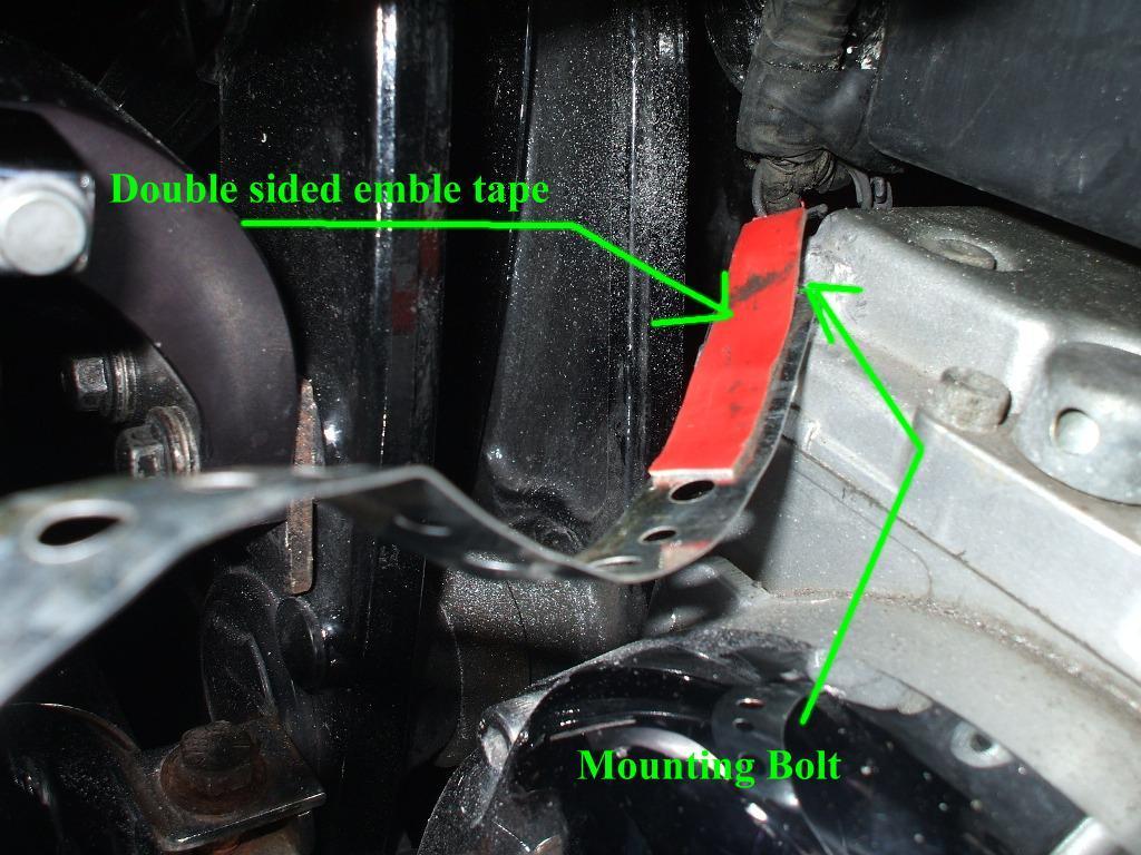
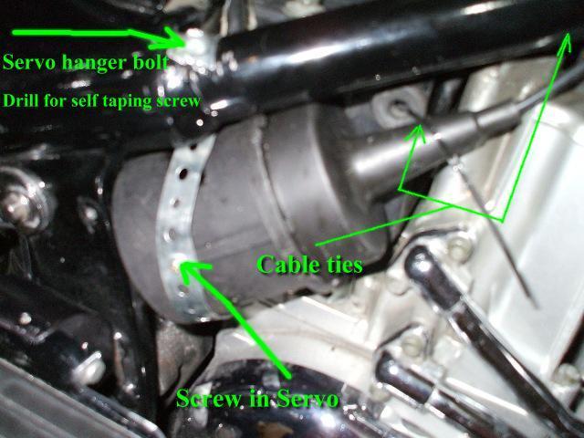
12 5. Mount the servo unit as seen in the left hand side. Re install the right hand side cover. Use cable ties and metal strapping to hold servo. It is a tight fit and it is hard to move without cable ties. The engine bolt needs to be shaved down about ½ inch then put countersink bolt in hole with the metal strapping. The picture shows to use rubber. I used double sided emblem tape so servo would not move. I used a die grinder to recess the bolt head down about 3/8 to ½ inch.
13

14 Vacuum line connections 1. Run the vacuum hose to the intake. If you still have the factory AIS system installed move the check valve to the intake to make the T connections. If not just cap off one end like in my picture. The larger end of check valve goes to the intake. There are a few riders out there that do not use a canister but the speed is not so stable. And for $10.00 it is worth the piece of mined. My test rides held my Road Star right on the exacted speed down hill and up hills. I don t put my bike in a strain so large inclines at slow speeds I change gears.

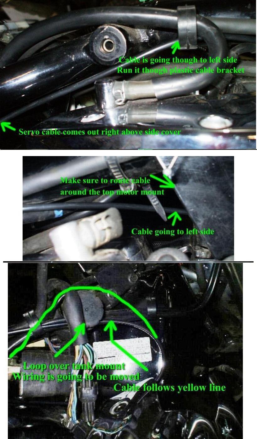
15 Servo Cable Installation: 1. Route the servo cable along the right side. Then under the frame to the left side right before the middle motor mount bracket. Bring it back though to the left side looping over the right side gas tank mount. Then down to the throttle cables. The Roads Stars have a push pull system for the throttle cables. We are going to hook to the pull side of the cables with the attached bracket supplied in the kit.
16

17 Throttle connection 1. First remove the carburetor from the intake. Remove choke knob and fuel lines. Disconnect the heater unit wires and the throttle position sensor wires. Leave the throttle cables on, just loosening the pull cable. I drilled an 11/64 hole just behind the pull cable link for the short wire loop supplied in the kit. Bolt is also in kit.

18 2. Connect the beaded chain to the short throttle wire loop. Note: Use a scratch awl or small screwdriver to open up the bead chain couplers they are very tight. Once installed, use pliers to carefully close them. 3. Connect the servo end with the wire loop with 5 beads of chain and the snaps in kit. 4. Reconnect throttle cable to the stock bracket on the top of carb. The throttle barrel from the throttle plate should line up with the pull cable with just a little clearance. Put blue locktight on nut side on bolt for extra protection. These big V twins do vibrate a little.
19

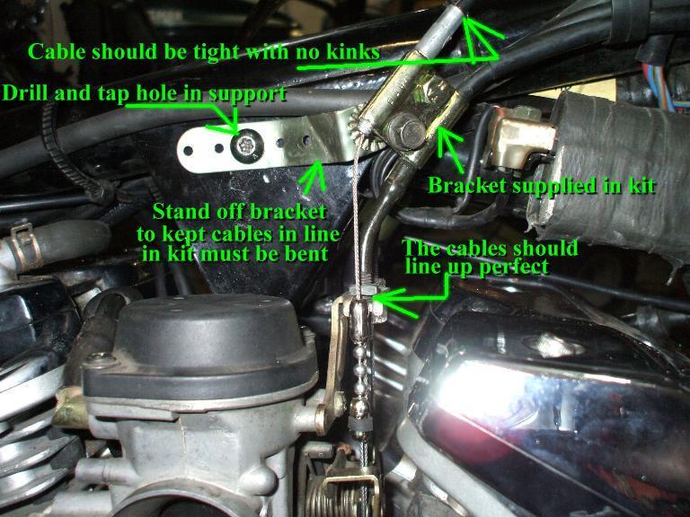
20 NOTES: Make sure there is no binding or interference between the throttle wire loop and the throttle cable. The throttle cable guide is only designed for one cable thickness, so it was necessary to move the wire loop past the pull cable barrel end. Test with wide open throttle from handlebars to see if cable follows in line with pull cable. There will be slack in the servo cable so make sure it follows cable guide on carb every time. Snap throttle a few times to see if it is working smooth and stays inline with pull cable. That is what the stand off bracket is for. I had no trouble without it but wanted it to be safe.


21 Wiring to the rear fender, Brake light Purple to Yellow. I ran the control pad power supply off the tail lights. I have a Tour-pak on my Road Star with a batwing fairing. I run leds in all the lights but the turning signals. If you do have leds as your stock brake lights you must install a relay. The cruise control circuit can not get a true 12v though an led. Not enough resistance.

22 In the newer Road Stars and Roadliners/Straoliner the brake light is led so you will need a simple mod for that also. Put the Diode and the two resistors in a water tight bottle. Drill holes for wires and seal with silicone. Or do the relay mod. You can also use a relay like this. Final steps: 1. Turn on the ignition key. Check to see that the CCS-100 turns on/off from the control pad. 2. Use a voltmeter to verify that the purple wire of the 10-pin connector gets 12 volts when either the front or rear brake is used (when the brake light is on).
23 3. Be sure all wiring, servo cable, and vacuum lines are secured. Be sure the beaded chain and loop do not rub on any wiring, vacuum lines, etc. 4. Reinstall the fuel tank and side panels 5. Use cable ties on servo cable and loose wires every where there is any loose play. Make sure not to make fast turns in servo cable. If the cable stays in place the better the cruise control response is. Testing the system: Find a convenient stretch of highway. When you are at speed, and away from other vehicles, turn the system on. Engage the system: Press SET and slowly relax your throttle hand. The system should regulate your selected speed Check the COAST and ACCEL functions. The CCS should lock in at the new speed. Check for proper disengagement: There are four ways to disengage: o 1. Front brake actuation o 2. Rear brake actuation o 3. Turn the system off (keypad switch or optional power switch) o 4. Sudden increase in engine RPM (clutch disengagement) My test ride results: Drove 53 miles total. 16 miles was Interstate riding. Test rides 5 th gear cruise works at 43 mph and up. 4 th gear 33 mph and up. When engine is running about 2000 rpm s is when cruise starts to work. I like the idea that it works in 4 th gear. I do some slow rides with local biker groups and we ride at 45 to 50 mph at times. The 2000 Road Stars have a 33 tooth front sprocket models and up have 32 tooth sprocket. That makes the gearing a little tall at that speed for the 1999 thru 2003 Road Stars. Both brake levers disengages cruise. A pull of the clutch disengages the cruise with a 1 second rpm surge of about 500 rpm s. Coast, Resume, and Accelerate all worked perfect. I bought my kit from murph@murphskits.com they had the best price. They also have kits in stock with extra parts and replacement Control pads if need. The install manuals can also be down loaded from there website. Parts not supplied with CCS-100: Cable ties, 8 Control pad bracket, shop made or available at Murphs' Kits. Murph at murph@murphskits.com A few bolts and nuts that most people have in there house. Water proof jacket for keypad sold by murph@murphskits.com Other items may be required, depending on your particular installation Don t forget the relay for the leds
24 Here are a few links you may look over where other model motorcycles have installed the CCS-100 and the Rostra cruise control. Rostra kits are going to be around $ more to install A few photos of my Road Star Ultra
Rostra Electronic Cruise Control Install On a Stratoliner or Roadliner
 Rostra Electronic Cruise Control Install On a Stratoliner or Roadliner MATERIALS LIST: 1 - Rostra Part # 250-1223 (www.brandondist.com/products/cruise1223.htm) 1 - Signal Splitter part # 250-4369 1 - Engagement
Installing the Audiovox CCS-100 Cruise Control.
 Installing the Audiovox CCS-100 Cruise Control. This article was written by: Lon Lawrence w650kawasaki@leaco.net Cruise Control : Audiovox CCS-100 ($89) Webpage : www.summitracing.com Message: I've installed
Triumph Street Triple VSM Grip Heater Install
 Triumph Street Triple VSM Grip Heater Install Introduction: With winter fast approaching and with painful memories of last winter riding with the club it was time to do something about getting some grip
Rostra Cruise Control Installation for the Honda ST1300
 Rostra Cruise Control Installation for the Honda ST1300 These instructions will only serve as a supplement to the Rostra Installation Manual to cover the particulars for installation in the ST1300. Remove
BMW 2002 M42 Swap Notes-THIS IS NOT FINISHED
 BMW 2002 M42 Swap Notes-THIS IS NOT FINISHED This document is to help those that want to install an m42 into a BMW 2002. It is based around an e30 engine, trans, and wiring. You can use the e36 block/head/wiring
Page 1. File: Motolight caliper one-piece Date: 8/14/2006
 Page 1 Caliper Mount Installation One-piece mounting brackets You should allow about two to three hours for installation. We suggest you use a well-lighted space for installation. PLEASE READ ALL THE INSTRUCTIONS.
INSTALLATION INSTRUCTIONS FOR THE TOMAHAWK ELECTRIC REVERSE
 INSTALLATION INSTRUCTIONS FOR THE TOMAHAWK ELECTRIC REVERSE LAST UPDATED: April 2018 Thank you for choosing the Motor Trike Electric Reverse. We ask that you read the directions before you start and follow
Installation Items: Cruise Module
 Installation Items: Rostra 250-1223, Electronic Cruise Control System (ECCS) includes the cruise module, harness, cruise cable, cruise module mounting bracket, cruise cable mounting bracket and hardware
Installation Instructions Z-Gate Shifter
 Installation Instructions Z-Gate Shifter Part Number 80681 1998, 2001 by B&M Racing and Performance Products The B&M Z-Gate shifter can be used in vehicles equipped with most popular three speed automatic
MICROCRUISE 4. INSTALLATION and OWNER S MANUAL FORM #2756, REV. E,
 MICROCRUISE 4 INSTALLATION and OWNER S MANUAL FORM #2756, REV. E, 07-30-09 THIS MANUAL, YOUR KIT AND YOU This Cruise Control Kit is a microprocessor based Cruise Control. It is designed for ease of installation
***THE OWNER'S MANUAL MUST BE GIVEN TO THE END USE CUSTOMER AFTER COMPLETING THE INSTALLATION.***
 INSTALLATION INSTRUCTIONS FOR THE MOTOR TRIKE HARLEY MECHANICAL REVERSE 1999-2006 FIVE SPEED FLH LAST UPDATED: OCTOBER 2011 AS THE INSTALLER OF THIS MECHANICAL REVERSE, YOU MUST BECOME FAMILIAR WITH PROPER
INTRODUCTION This Cruise Control Kit is a microprocessor based Cruise Control. It is designed for ease of installation and can be used with most cars,
 ELECTRONIC CRUISE CONTROL INSTALLATION MANUAL Installation Operation Trouble Shooting FORM #2239, Rev. K, 08/17/01 INTRODUCTION This Cruise Control Kit is a microprocessor based Cruise Control. It is designed
Procharger Stage II Intercooled Supercharger System (11-14 GT)
") Procharger Stage II Intercooled Supercharger System (11-14 GT) Installation Time: Approximately one day. Installed on 2012 Mustang GT 5.0/Manual Required Tools 3/8 Socket Set (Standard and Metric) 1/2
Procharger Stage II Intercooled Supercharger System (11-14 GT) Installation Time: Approximately one day. Installed on 2012 Mustang GT 5.0/Manual Required Tools 3/8 Socket Set (Standard and Metric) 1/2
CAUTION: READ INSTRUCTIONS CAREFULLY BEFORE STARTING INSTALLATION
 V-Twin MFG. VT No. 32-9500 V-TECH 1 IGNITION KIT, SINGLE FIRE FITS EV SHOVEL, XL THRU 1997 VT No. 32-9503 V-TECH 1 IGNITION KIT, SINGLE FIRE FITS EV, SHOVEL, XL, WITH COIL AND WIRES This is a custom application
Installation of the AdMore Premium Light Bar on an Indian Motorcycle
 Installation of the AdMore Premium Light Bar on an Indian Motorcycle May 16, 2017 by Ken the Mucker Sexton Ref: AdMore Lighting, LED8020-SB, Premium LED Light Bar with Smart Brake Technology, https://www.admorelighting.com/product/admore-smt-light-bar-with-smart-brake-technology-new/
BA /02/03/04/06/07/08/13/13B/15 BIG AIR KIT (BAK) - Yamaha Road Star (99-07)
 - Yamaha Road Star (99-07)") BA-2020-00/02/03/04/06/07/08/13/13B/15 BIG AIR KIT (BAK) - Yamaha Road Star (99-07) Page: 1 Revision: 6.2-02/23/2011 Install Time: 1.5 Hours We recommend a qualified Yamaha technician install this kit
BA-2020-00/02/03/04/06/07/08/13/13B/15 BIG AIR KIT (BAK) - Yamaha Road Star (99-07) Page: 1 Revision: 6.2-02/23/2011 Install Time: 1.5 Hours We recommend a qualified Yamaha technician install this kit
Z-Gate Universal Shifter
 Installation Instructions Z-Gate Universal Shifter Fits: GM, Ford, Lincoln and Chrysler Transmissions See Application Guide for Specific Applications Part #80681 Rev 06/01/2018 WORK SAFELY! For maximum
WARNING! USE ONLY IN RACE OR OTHER CLOSED COURSE APPLICATIONS AND NEVER ON PUBLIC ROADS
 2010-2013 Kawasaki Z1000 2011-2013 Kawasaki Ninja 1000 Z-Fi TC / Z-FI QS INSTALLATION INSTRUCTIONS P/N s S490S, S490R, T490S, T490R WARNING! USE ONLY IN RACE OR OTHER CLOSED COURSE APPLICATIONS AND NEVER
Be sure to read and go over all pages before you start your installation
 Yamaha Gen-2 V-MaxV Holeshot Superbike Bars Installation Guide Pre-Installation Note Be sure to read and go over all pages before you start your installation Preparation for Installation A) It is recommended
Connecting the rear fog light on the A4 Jetta, while keeping the 5 Light Mod
 Connecting the rear fog light on the A4 Jetta, while keeping the 5 Light Mod DISCLAIMER: I'm human and make mistakes. If you spot one in this how to, tell me and I'll fix it This was done on my 99.5 Jetta.
PRXB EXHAUST BRAKE MAXIMUM EXHAUST FLOW DESIGN
 MAXIMUM EXHAUST FLOW DESIGN PRXB EXHAUST BRAKE C44072/C44073/C44074/C44075/C44076 APPLICATION: 994-2002 DODGE RAM TRUCKS W/5.9L CUMMINS DIESEL ENGINES WITH MANUAL & AUTOMATIC TRANSMISSIONS STOCK DODGE
PRXB EXHAUST BRAKE HIGH PERFORMANCE
 HIGH PERFORMANCE PRXB EXHAUST BRAKE C44059, C4406, C44063, C44065 APPLICATION 994-2002 DODGE RAM AUTOMATIC TRUCKS EQUIPPED WITH 47RE TRANSMISSIONS WITH 5.9L, 24 VALVE CUMMINS DIESEL ENGINES GETTING STARTED
72 Mustang Mach 1 tachometer cluster and gauge conversion
 72 Mustang Mach 1 tachometer cluster and gauge conversion Dated: 02-17-2009 (drafted by a Chevy person working on his first Ford -not good-) Revised: 11-05-2010 The following information pertains to how
Remove the 3-11mm nuts holding mirror on. Don t drop the nuts!
 2005-2012 Ford Mustang Puddle Lamp Kit Parts List: Quantity: Tool List: LED Lamps 2 Flat head screwdriver Seals 2 Ratchet & Socket set OR Nuts 2 Adjustable Wrench Wiring harness 1 Drill & 11/16 th bit
INSTALLATION MANUAL AP60B INSTALLATION MANUAL
 INSTALLATION MANUAL 2. TOOLS REQUIRED The following is a list of tools required to properly install the cruise control. While this unit may be installed without some of the tools listed, it is recommended
C40008 & C40009 EXHAUST BRAKES
 EXHAUST BRAKES C40008 & C40009 1995 2003 Ford F250 / F350 7.3 L Powerstroke Diesel with manual transmissions 1995 1998 Ford F250 / F350 7.3 L Powerstroke Diesel with automatic transmission* *Requires the
CCS-100 ELECTRONIC CRUISE CONTROL INSTALLATION MANUAL
 CCS-100 ELECTRONIC CRUISE CONTR NTROL INSTALLA ALLATI TION MANUAL INDEX Page 1. Cruise Control Installation:... 1 Parts List... 2 Throttle Connections... 3 Wiring... 4 2. Control Switch Installation...
TRIUMPH ST ROSTRA ELECTORNIC CRUISE CONTROL
 TRIUMPH ST 1050 - ROSTRA ELECTORNIC CRUISE CONTROL There have been a number of threads discussing the pros and cons of electronic vs throttle lock cruise controls. Living in Texas can require some long
1963 GEN IV SUREFIT VINTAGE AIR CONDITIONING INSTALLATION
 by Randy Irwin 1963 GEN IV SUREFIT VINTAGE AIR CONDITIONING INSTALLATION Randy Irwin - Technical Writer Randy has been involved in the Chevy parts business for over 30 years. He is a wizard at creating,
This is what we are trying to create in the steps below
 You will need: (1) Some 3/4 aluminium or steel flat bar (+/- 1 foot) (2) About 12 of 3 Aluminium or steel tubing. (2) Piece of 3X3 silicone hose and 2 hose clamps (3) 1 K&N (or similar) high flow filter
INSTALLATION INSTRUCTIONS FOR THE MOTOR TRIKE CROSS COUNTRY / CROSS ROADS / HARD BALL RAKE KIT
 INSTALLATION INSTRUCTIONS FOR THE MOTOR TRIKE CROSS COUNTRY / CROSS ROADS / HARD BALL RAKE KIT Thank you for choosing the Motor Trike Cross Country / Cross Roads / Hard Ball rake kit. We ask that you read
ULTRACRUISE CONTROL INSTALLATION MANUAL
 ULTRACRUISE CONTROL INSTALLATION MANUAL Installation Operation Trouble Shooting FORM # 2784 Rev. A 07/95 THIS MANUAL, YOUR KIT AND YOU This Cruise Control Kit is a microprocessor based Cruise Control.
SUZUKI SV
 SUZUKI SV650 2007-2011 Z-Fi QS (Quickshift) / Z-Fi TC (Traction Control) Installation Instructions Part # T640 May result in the activation of the FI light (indicating injector fault) but does NOT cause
INSTALLATION INSTRUCTIONS
 Rear Vision System Tailgate Emblem Camera Mirror Display 2009-Current Ford F-150 and 2010-Current Super Duty (Kit part number 1008-9527) Kit Contents: Mirror Tailgate Emblem Mount with Camera Interior
Go-ped ESR750 / ESR750EX Rear Brake Installation Instructions
 Go-ped ESR750 / ESR750EX Rear Brake Installation Instructions This kit provides all the parts you need to install a rear brake on your ESR750 or ESR750EX. It will not work on an ESR Sport, or other Go-ped
C FORD F250 / F L POWERSTROKE DIESEL WITH AUTOMATIC TRANSMISSIONS ONLY
 EXHAUST BRAKES C40019 1999-2003 FORD F250 / F350 7.3L POWERSTROKE DIESEL WITH AUTOMATIC TRANSMISSIONS ONLY Getting Started Thank you and congratulations on your purchase of a Pacbrake exhaust retarder.
Page 1. File: Motolight caliper one-piece Harley Date: 8/15/2006
 Page 1 Harley-Davidson FL Caliper Mount Installation One-piece mounting brackets You should allow about two to three hours for installation. We suggest you use a well-lighted space for installation. PLEASE
Installation Manual v1.0: Aurora Plus Turbo Kit ( ) 5.9L Dodge. Please read all instructions before installation.
 5.9L Dodge. Please read all instructions before installation.") Installation Manual v1.0: Aurora Plus - 4000 Turbo Kit (2003-2007) 5.9L Dodge Please read all instructions before installation. Figure 1: Aurora Plus - 4000 Kit Contents 1 Figure 2: Aurora Plus Hardware
Installation Manual v1.0: Aurora Plus - 4000 Turbo Kit (2003-2007) 5.9L Dodge Please read all instructions before installation. Figure 1: Aurora Plus - 4000 Kit Contents 1 Figure 2: Aurora Plus Hardware
Shotgun Double Barrel HPFP install guide
 Shotgun Double Barrel HPFP install guide Thank you for your purchase of the VTT Shotgun Double Barrel HPFP upgrade! First thing to do when you open your box is to make sure all parts are in their respective
4 th Gen 4 Runner Front Bumper - Installation Instructions:
 www.shrockworks.com info@shrockworks.com 877-474-7625 4 th Gen 4 Runner Front Bumper - Installation Instructions: Thank you for purchasing a ShrockWorks product. We are confident you will enjoy it for
BMW S1000RR Z-Fi QS / Z-Fi TC Installation Instructions P/N S541S, S541R, T541S, T541R
 2009-2013 BMW S1000RR Z-Fi QS / Z-Fi TC Installation Instructions P/N S541S, S541R, T541S, T541R WARNING! USE ONLY IN RACE OR OTHER CLOSED COURSE APPLICATIONS AND NEVER ON PUBLIC ROADS Z-Fi products do
INSTALLATION INSTRUCTIONS for HI-4 DUAL FIRE MOTORCYCLE IGNITION. Part Number INTRODUCTION REMOVAL OF POINTS IGNITION TO 1977 MODELS
 INSTALLATION INSTRUCTIONS for HI- DUAL FIRE MOTORCYCLE IGNITION Part Number -00 CAUTION: READ INSTRUCTIONS CAREFULLY BEFORE STARTING INSTALLATION INTRODUCTION The HI- ignition system is intended for use
PRODUCT SAFETY NOTICE DEALER/INSTALLER NOTICE
 PRODUCT SAFETY NOTICE Congratulations. This vehicle has been equipped with a Firestone air suspension system. This suspension will enhance the vehicle s handling when loaded, however, the vehicle s performance
RECOMMENDED TOOLS PERSONAL & VEHICLE PROTECTION SAFETY GLASSES
 PART NUMBER: 250-1873 GENERAL APPLICABILITY ALL MODELS RECOMMENDED TOOLS PERSONAL & VEHICLE PROTECTION SAFETY GLASSES KIT CONTENTS/SERVICE PARTS ITEM QTY DESCRIPTION PART# 1 1 CRUISE CONTROL MODULE 250-2791
JEEP WRANGLER (TJ), UNLIMITED (TJL), RUBICON MODELS BODY LIFT KIT INSTALLATION INSTRUCTIONS KIT# KIT# 973
, UNLIMITED (TJL), RUBICON MODELS BODY LIFT KIT INSTALLATION INSTRUCTIONS KIT# KIT# 973") JEEP WRANGLER (TJ), UNLIMITED (TJL), RUBICON MODELS BODY LIFT KIT INSTALLATION INSTRUCTIONS 1997-2006 2 KIT# 972 3 KIT# 973 WARNING Installation of a Performance Automotive Group body lift will change
JEEP WRANGLER (TJ), UNLIMITED (TJL), RUBICON MODELS BODY LIFT KIT INSTALLATION INSTRUCTIONS 1997-2006 2 KIT# 972 3 KIT# 973 WARNING Installation of a Performance Automotive Group body lift will change
SCION FRS FOG LIGHTS. Part Number: SFR-313
 Part Number: SFR-313 Kit Contents Item # Quantity Reqd. Description 1 2 Light Housings 2 2 Fog Light bezels 3 1 Harness bag 4 1 User s card 5 1 Switch 6 1 Fuse jumper Hardware Bag Contents Item # Quantity
06-15 ECU, Battery and Washer Bottle Relocation
 06-15 ECU, Battery and Washer Bottle Relocation On the 2006-2015 MX-5, there is a very narrow middle section between the battery box and the air filter box to remove heat. For the most part, this design
PRODUCT SAFETY NOTICE
 PRODUCT SAFETY NOTICE Congratulations. This vehicle has been equipped with a Firestone air suspension system. This suspension will enhance the vehicle s handling when loaded, however, the vehicle s performance
SUZUKI SV
 SUZUKI SV650 2007-2011 Z-Fi Installation Instructions Part # F640 May result in the activation of the FI light (indicating injector fault) but does NOT cause actual running issues Parts List: Z-Fi Control
WARNING: the engine does not come with oil in it. Please fill the oil before starting. The 200cc hardknock requires 9/10 of a quart of oil.
 WARNING: the engine does not come with oil in it. Please fill the oil before starting. The 200cc hardknock requires 9/10 of a quart of oil. Things needed for assembly. -2 tubes of blue loc-tite. I don
U L T I M A T E R A D A R / L A S E R D E F E N S E S Y S T E M
 S m a r t e r Q u i e t e r M o r e A c c u r a t e U L T I M A T E R A D A R / L A S E R D E F E N S E S Y S T E M Installation Manual PASSPORT 9500ci Comes Complete Front Radar Receiver Miniature weatherproof
INSTALLATION INSTRUCTIONS
 Rear Vision System Tailgate Emblem Camera Aftermarket Display 2009-Current Ford F-150 and 2010-Current Super Duty (Kit part number 1008-6509) Kit Contents: Tailgate Emblem Mount with Camera Chassis Harness
TCI FastGate Shifter Installation Instructions
 151 INDUSTRIAL DRIVE ASHLAND, MISSISSIPPI 38603 http://www.tciauto.com TELEPHONE: 662-224-8972 FAX LINE: 662-224-8255 E-MAIL: tech@tciauto.com TCI 616541 FastGate Shifter Installation Instructions The
MSD 6AL Ignition Module w/ Rev Control - Installation Instructions
 MSD 6AL Ignition Module w/ Rev Control - Installation Instructions The below installation instructions work for the following products: MSD 6AL Ignition Module w/ Rev Control Please read through the instructions
Total installation time for the cruise control was approximately 8 hours.
 The following summary highlights the start-to-finish install of an Audiovox cruise control on stellarpod s (Steve) ST1300. Fred D (Fred) and ChucksKLRST (Chuck) primarily performed the install (Steve did
Torque Convertor Control System
 1 BD AutoLoc Torque Convertor Control System Part# 1030390 Installation Manual for the following applications: BD Brakes for Dodge, Ford and Chevrolet Pac Brake for Dodge & Ford Jacobs E-Brake for 1994-98
CRUISE CONTROL SYSTEM
 CRUISE CONTROL SYSTEM 1988 Jeep Cherokee 1988 Cruise Control Systems JEEP CRUISE COMMAND All Models DESCRIPTION & OPERATION Jeep vehicles use an electro-mechanical servo system. The system consists of
We thank you for purchasing a manual petcock conversion kit from Murphs!
 We thank you for purchasing a manual petcock conversion kit from Murphs! The first step is removing the gas tank from the bike. We suggest running the tank down to reserve before removal, both for the
Installation Instructions Harley-Davidson Saddlebag Lids
 Installation Instructions Harley-Davidson Saddlebag Lids Thank you for your purchase of Bagger Audio Saddlebag Lids for your Harley- Davidson motorcycle. We have carefully engineered these products to
Z-Fi TC Installation Instructions Part # F4418/T4418. In order to fit the Bazzaz quickshifter on this application, aftermarket rearsets must be used
 Kawasaki ZX14R 2016 Z-Fi TC Installation Instructions Part # F4418/T4418 In order to fit the Bazzaz quickshifter on this application, aftermarket rearsets must be used Parts List: Z-Fi or Z-Fi TC Control
EDELBROCK THUNDER SERIES AVS CARBURETORS Part #1801, 1802, 1803, 1804, 1805, 1806, 1812, 1813, 1825, 1826 INSTALLATION INSTRUCTIONS
 EDELBROCK THUNDER SERIES AVS CARBURETORS Part #1801, 1802, 1803, 1804, 1805, 1806, 1812, 1813, 1825, 1826 INSTALLATION INSTRUCTIONS IMPORTANT NOTE: Proper installation is the responsibility of the installer.
Backwater Performance Systems Large Vanguard Mikuni Twin Carburetor Kit
 Backwater Performance Systems Large Vanguard Mikuni Twin Carburetor Kit 1. Throttle Cable Twin (CKC-41) 2. Carburetor VM30mm (CKC-40) 3. Loctite 242.5mL (A-210) 4. Air Cleaner Filter 6000 (EC-86) 5. Rev
CRUISE CONTROL SYSTEM
 CRUISE CONTROL SYSTEM 1992 Infiniti G20 1991-92 SAFETY EQUIPMENT Infiniti Cruise Control Systems G20, M30, Q45 DESCRIPTION & OPERATION NOTE: For system component locations, see SYSTEM COMPONENT LOCATIONS.
INSTALLATION INSTRUCTIONS
 Rear Vision System Liftgate Emblem Camera Mirror Display 2009-2012 Ford Flex (Kit part number 1008-9527) Kit Contents: Mirror Liftgate Emblem Mount with Camera Interior (shorter) Harness Chassis (longer)
INSTALLATION INSTRUCTIONS for HI-1 and HI-2 MOTORCYCLE IGNITIONS. Part Numbers and INTRODUCTION COIL AND SPARK PLUG CABLE CONSIDERATIONS
 INSTALLATION INSTRUCTIONS for HI- and HI- MOTORCYCLE S Part Numbers 8-000 and 8-000 CAUTION: READ INSTRUCTIONS CAREFULLY BEFORE STARTING INSTALLATION INTRODUCTION Crane HI- and HI- ignition systems are
Last Revision: 30JN THRU 1979 C3 CORVETTE STANDARD (NON-ADJUSTABLE) STEERING COLUMN DISASSEMBLY & REPAIR INSTRUCTIONS PAPER #2
 STEERING COLUMN DISASSEMBLY & REPAIR INSTRUCTIONS PAPER #2") Last Revision: 30JN2007 1969 THRU 1979 C3 CORVETTE STANDARD (NON-ADJUSTABLE) STEERING COLUMN DISASSEMBLY & REPAIR INSTRUCTIONS PAPER #2 Disassembly and Repair Instructions Addressed in this Paper Degree
Last Revision: 30JN2007 1969 THRU 1979 C3 CORVETTE STANDARD (NON-ADJUSTABLE) STEERING COLUMN DISASSEMBLY & REPAIR INSTRUCTIONS PAPER #2 Disassembly and Repair Instructions Addressed in this Paper Degree
2010 Honda VFR 1200F Z-Fi QS / Z-Fi TC Installation Instructions P/N S350S, S350R, T350S, T350R
 R 2010 Honda VFR 1200F Z-Fi QS / Z-Fi TC Installation Instructions P/N S350S, S350R, T350S, T350R WARNING! USE ONLY IN RACE OR OTHER CLOSED COURSE APPLICATIONS AND NEVER ON PUBLIC ROADS Z-Fi products do
Thank you for choosing the Techlusion Electronic Jet Kit, the TFI. The TFI is usable for sequential fuel injection 2 cylinder Suzuki motorcycles **.
 Rev 1.1.1 2055ST TFI TFI Patent Numbers: 7,000,599 & 7,124,742 TFI Instructions Suzuki Thank you for choosing the Techlusion Electronic Jet Kit, the TFI. The TFI is usable for sequential fuel injection
Bonneville/Thruxton A.R.K. Guide
 Kit Includes: 1. Hardware 2. 3M Double Sided Tape 3. Jet Kit 4. Carburetor Support Brace 5. 2 x K&N Air Filters 6. Crankcase Breather Filter Fits The Following Motorcycles: Triumph Thruxton Triumph Bonneville
Installation Instructions
 Suzuki Samurai 1 Inch and 2 Inch Body Lift Kit (SKU# SSP-BL) Installation Instructions Background: These instructions are designed for installing the 2 body lift. Our approach is to raise the entire body
TTR225/250 DUAL S PORT K IT I NSTALLATION I NSTRUCTIONS
 TTR225/250 DUAL S PORT K IT I NSTALLATION I NSTRUCTIONS KIT CONTENTS Inspect Your Kit Your kit will include the following items A. TTR225/250 Instructions and Wiring Diagrams Read through the entire instruction
Part Number: SFR-713. Hardware Bag Contents. General Applicability All models. Conflicts - Fog Lights. Date: SCION FRS LED DRL
 Date: 01.30.2014 SCION FRS 2013-2015 LED DRL Part Number: SFR-713 Kit Contents Item # Quantity Reqd. Description 1 2 DRL s bezels w/led DRL 2 1 Driver Box 3 1 Harness bag 4 1 User s card 5 1 Switch Hardware
GL1800 TRAILER HITCH - INSTALLATION INSTRUCTIONS #GL
 GL1800 TRAILER HITCH - INSTALLATION INSTRUCTIONS #GL18007-20 Read through these instructions completely before attempting installation, lay out all pieces including the numbered hardware bags to familiarize
Building Tips by PMD For Wedico Trucks
 Building Tips by PMD For Wedico Trucks These are in no particular order but will help you with building! Below are some methods we have found to ease the assembly of these models. If you have any ideas
Honda VFR 1200F Z-Fi Installation Instructions P/N F350
 2010-2012 Honda VFR 1200F Z-Fi Installation Instructions P/N F350 WARNING! USE ONLY IN RACE OR OTHER CLOSED COURSE APPLICATIONS AND NEVER ON PUBLIC ROADS Z-Fi products do not meet California CARB highway
Torque Convertor Control System
 22 September 2015 PN#1030395 TorqLoc (I-00208) 1 BD TorqLoc Torque Convertor Control System Part# 1030395 Installation Manual for the following applications: BD Brakes for Dodge, Ford and Chevrolet Pac
Ducati 848 Streetfighter
 Ducati 848 Streetfighter 2012-2013 Z-Fi Installation Instructions Part # F193 Parts List: Z-Fi Control Unit Fuel Harness O2 Eliminator (2) Scotchlok (2) Cable Ties Velcro USB Cable Swingarm Stickers Download
YAMAHA YZF R
 YAMAHA YZF R1 2009-2012 Z-Fi QS (Quickshift) / Z-Fi TC (Traction Control) Installation Instructions Part #s 800805CS, 800805CR, 800805TS, 800805TR Parts List: Z-Fi QS/TC Control Unit Fuel Harness Coil
NEW VINTAGE INSTRUMENT AND GAUGE KIT INSTALLATION INSTRUCTIONS
 NEW VINTAGE INSTRUMENT AND GAUGE KIT INSTALLATION INSTRUCTIONS REV.01-033113 INDEX THE BASICS CLUSTER INSTALLATION TACHOMETER OPERATION SPEEDOMETER OPERATION TROUBLESHOOTING WIRING DIAGRAM pg.2 pg. 2 pg.
Ford Racing 4.6L 3V Crate Engine Control Pack
 Ford Racing 4.6L 3V Crate Engine Control Pack Installation Time: 3-6 hours on a Foxbody Mustang Tools Required: Basic English and Metric Socket and Wrench Set Flat and Phillips Screwdrivers Torx bits Hammer
INSTALLATION INSTRUCTIONS
 OEM Recessed Lip Camera with Harness and Slimline Mirror (Kit part number 9002-8724) Please read thoroughly before starting installation and check that kit contents are complete. Items Included in the
2004 KIA RIO CRUISE CONTROL INSTALLATION INSTRUCTIONS PART NO AUTOMATIC TRANSMISSION VEHICLE CONTENTS
 2004 KIA RIO AUTOMATIC TRANSMISSION VEHICLE CRUISE CONTROL INSTALLATION INSTRUCTIONS PART NO. 250-1766 CONTENTS PARTS IDENTIFICATION... 2 HELPFUL HINTS... 3 INSTALLATION... 4 WIRING DIAGRAM... 11 TROUBLESHOOTING
Sherco Setup and Lubrication Guide
 Sherco Setup and This guide is designed to provide the Sherco owner with instructions on how to: Set up a new bike Clean and re-oil the air filter Change the transmission oil Change the fork oil Repack
Tusk Pannier Racks. Instructions and information KLR
 1 Tusk Pannier Racks Instructions and information KLR650 2008 + Congratulations on your purchase of the Tusk Pannier Racks. These racks are made to handle extreme adventure riding, but work great for the
1996+ Yamaha G16 / G22 Yamaha G29/YDRA Drive
 Vegas Carts & Performance 2995 Coleman St North Las Vegas, NV 89032 702-530-7753 VegasCarts.com 625cc Big Block Installation Instructions 1996+ Yamaha G16 / G22 Yamaha G29/YDRA Drive Revised 8/6/2018 1
750 Paso Wiring Upgrade
 750 Paso Wiring Upgrade Supplies required: 2 Bosch 30A/12V Relays # #0 332 209 150 (with mounting tab) 1 30 Amp fuse holder 1 10 Amp fuse holder 12 inches of brown 12 gauge wire 60 inches of red 14 gauge
Parts List. Please be sure to read our instructions thoroughly before attempting installation. D2/G2 Parts List. D31/G31 Parts List.
 Parts List Please be sure to read our instructions thoroughly before attempting installation. D2/G2 Parts List D31/G31 Parts List Page 2 1 Step 1: Bike Preparation Step 1: Bike Preparation There are two
Wolverine Turn Signal / Horn Kit 2102
 All years Yamaha Wolverine STOP - THIS KIT IS DESIGNED SPECIFICALLY FOR ALL YEAR AND MODELS YAMAHA WOLVERINE. IF YOUR MACHINE IS NOT ONE OF THESE MODELS DO NOT PROCEED. Contact Ryco Motorsports or your
Installation Instructions Jeep CJ-7
 Retrofit Steering Column Installation Instructions 1976-86 Jeep CJ-7 For Part # s 1520800010, 152800020, 1520800051 www.ididitinc.com 610 S. Maumee St., Tecumseh, MI 49286 (517) 424-0577 (517) 424-7293
Chevy Colorado / GMC Canyon INSTALL GUIDE
 Chevy Colorado / GMC Canyon INSTALL GUIDE S-TECH Switch Systems DEVELOPED, DESIGNED, MANUFACTURED and Assembled in the Rocky Mountains of Colorado, known to many as JEEP COUNTRY. Trail riding at 10,000
WARNING! USE ONLY IN RACE OR OTHER CLOSED COURSE APPLICATIONS AND NEVER ON PUBLIC ROADS
 2008-2010 Ducati 848 / 2009-2011 Ducati 1198 & 1198S & 1198 SP / 2011-2012 Ducati 848 EVO Z-Fi INSTALLATION INSTRUCTIONS P/N s F142, F144, F146 WARNING! USE ONLY IN RACE OR OTHER CLOSED COURSE APPLICATIONS
OIL COOLER KIT INSTALLATION INSTRUCTIONS PART NUMBER D
 OIL COOLER KIT INSTALLATION INSTRUCTIONS PART NUMBER D570-0907 APPLICATION: 2011-12 E90 335i/xi (N55 engine) with BMW M-Technic bumper and without stock oil cooler Congratulations for being selective enough
Installing LED lights in a Hypercharger By Keith Edwards Joker s Wild! (Wildjokr)
") Installing LED lights in a Hypercharger By Keith Edwards Joker s Wild! (Wildjokr) THINGS YOU WILL NEED: A Hypercharger (duh!) LEDs (The ones I got were from Benny Bryant at Fantasies on Wheels in Sylacauga,
Installing LED lights in a Hypercharger By Keith Edwards Joker s Wild! (Wildjokr) THINGS YOU WILL NEED: A Hypercharger (duh!) LEDs (The ones I got were from Benny Bryant at Fantasies on Wheels in Sylacauga,
KIA RIO CRUISE CONTROL INSTALLATION INSTRUCTIONS PART NO AUTOMATIC TRANSMISSION VEHICLE CONTENTS
 2007-2008 KIA RIO AUTOMATIC TRANSMISSION VEHICLE CRUISE CONTROL INSTALLATION INSTRUCTIONS PART NO. 250-1799 CONTENTS PARTS IDENTIFICATION... 2 HELPFUL HINTS... 3 INSTALLATION... 4 WIRING DIAGRAM... 11
Installation Manual for Dodge 24V Cummins Version 3.1. Please read all instructions before the installation of the ATS Co-Pilot
 10/1/12 601-900-2218-INST Installation Manual for 1998.5-2002 Dodge 24V Cummins Version 3.1 Please read all instructions before the installation of the ATS Co-Pilot Thank you for purchasing the ATS Co-Pilot
installation manual 123\TUNE+-2CV
 installation manual 123\TUNE+-2CV Installation Instructions The 123\TUNE+-2CV is designed for the stock (BLACK) 2CV-coil STEP 1 Turn the ignition off. Remove the engine fan use a long 14 mm socket or
Part Number: TAV-713 TOYOTA AVALON LED DRL
 Part Number: TAV-713 Kit Contents Item # Quantity Reqd. Description 1 2 DRL s bezels w/led DRL 2 1 Driver Box 3 1 Harness bag 4 1 User s card 5 1 Cushion pad 6 1 Switch 7 2 Drill Jigs Hardware Bag Contents
WARNING! USE ONLY IN RACE OR OTHER CLOSED COURSE APPLICATIONS AND NEVER ON PUBLIC ROADS
 2010-2013 Ducati Streetfighter Z-Fi TC / Z-FI QS INSTALLATION INSTRUCTIONS P/N s S190S, S190R, T190S, T190R WARNING! USE ONLY IN RACE OR OTHER CLOSED COURSE APPLICATIONS AND NEVER ON PUBLIC ROADS Z-Fi
R O A D S M I T H TRIKE CONVERSIONS BY THE TRIKE SHOP
 R O A D S M I T H TRIKE CONVERSIONS BY THE TRIKE SHOP Please thoroughly review the instructions before and during installation. Keep in mind that this product was designed to be installed by trained dealer
Prepare the cargo area for storage of under-hood parts, removed as interference. (Put down blankets.)
") PCU Replacement Procedure John Mayer Hawthorne Auto Clinic 1-28-2014 updated 1-20-2016 Overall notes: It is preferable to perform the PCU replacement procedure on a lift, or to have access to under the
PCU Replacement Procedure John Mayer Hawthorne Auto Clinic 1-28-2014 updated 1-20-2016 Overall notes: It is preferable to perform the PCU replacement procedure on a lift, or to have access to under the