Link Mfg. Ltd th St. NE Sioux Center, IA USA
|
|
|
- Bruce Carroll
- 6 years ago
- Views:
Transcription


1 OWNER S MANUAL UltraRide Chassis Air Suspension ELECTRONIC AIR CONTROL KIT Model # 800M1400 Lot/Serial# Questions? Contact this Professional Installer : Company : Phone : Installer : Date : Please Read this manual before operating your UltraRide Suspension, and keep it for future reference. Link Mfg. Ltd th St. NE Sioux Center, IA USA For questions with your UltraRide suspension system, please call Toll Free Internet Address: YOUR TRUST OUR PASSION! 1
2 Contents 1. INTRODUCTION LINK LIMITED WARRANTY AIR SYSTEM OPERATION SERVICE & MAINTENANCE TROUBLESHOOTING FUSES... 8 ELECTRONIC AIR CONTROL KIT... 9 PARTS LIST... 9 OPTIONAL CONTROL PANEL PARTS LIST CHASSIS INTEGRATION WIRING HARNESS ELECTRICAL SCHEMATIC INTERNAL WIRING HARNESS ELECTRICAL SCHEMATIC PNEUMATIC SCHEMATIC AIR KIT CONTROL PANEL ELECTRICAL SCHEMATIC INTRODUCTION Thank you for choosing the Link UltraRide Electronic Air Control Kit for your vehicle. With no lubrication required and only periodic maintenance as indicated in this manual, your UltraRide system will provide many miles of reliable, trouble free service. In the unlikely event of a suspension malfunction between regular vehicle maintenance intervals, immediate corrective action should be taken to prevent further suspension damage. Our website, can locate a Link dealer near you. The UltraRide Electronic Air Control Kit is intended ONLY to provide a pressurized air supply for Link UltraRide Chassis Suspensions and control the lift and dump action of the suspension. Any other use of these Air Control Products is not authorized. responsibility for damage resulting from misuse. Link Mfg., Ltd. Accepts no warranty The UltraRide Electronic Air Control Kit provides a convenient and dependable control system for your UltraRide suspension system. The Electronic Air Control Kit both provides a source of compressed air for the suspension as well as controls the height of the suspension. 2

3 OWNER RESPONSIBILITIES The UltraRide Electronic Air Control Kits need no lubrication and requires only a little maintenance. However, immediate corrective action should be taken if a serious malfunction occurs. o Owner is solely responsible for pre-operation inspection, periodic inspections, maintenance, and use of the product as specified in the particular Link Mfg., Ltd. Instructions available by product model, except as provided in warranty, and for maintenance of other vehicle components. o Owner is responsible for all down time expenses, cargo damage, and all business costs and losses resulting from a warrantable failure. SAFETY SYMBOLS, TORQUE SYMBOL, and NOTES 3
4 2. LINK LIMITED WARRANTY ULTRARIDE ELECTRONIC AIR KIT 800M1400 What Is Covered This warranty covers any defects in materials or manufacture. This warranty does not cover ordinary wear and tear, routine maintenance, or damage caused by alteration or improper installation, use, or maintenance of the Product. How Long Coverage Lasts For all components including the air compressor, this warranty runs for 3 years from the date the Product was sold to its original end-user (the Sale Date ) or 60,000 miles, whichever occurs first. What Link Will Do Link will repair or replace any Product that does not conform to this warranty. Link will also reimburse for installation of repaired or replacement parts as follows: Labor Description Hours Hourly Rate Relay 0.75 $90.00 ECU 1 $90.00 Compressor 1 $90.00 Manifold 1.3 $90.00 Inclination Sensor 0.5 $90.00 Rotary Sensor X1 0.5 $90.00 Harness 1.5 $90.00 Internal Fuse 0.6 $90.00 How To Get Warranty Service Telephone Link Customer Service at You may also take the Product to any authorized Link distributor or dealer. You will be responsible for removing the Product from the vehicle and shipping it to Link at your expense. You must submit documentation of the date and vehicle mileage when the Product was sold to its original end-user and the vehicle s current mileage. Limitations & Exclusions Link will not be responsible for incidental or consequential damages, including loss of use or profits. LINK DISCLAIMS ANY WARRANTY OF MERCHANTABILITY OR FITNESS FOR A PARTICULAR PURPOSE. This warranty does not apply if the Product is used with accessories not approved by Link or when other than Link Genuine Replacement Parts have been installed on the Product. Link does not warrant accessories supplied by Link that bear the name of another company. Link reserves the right to provide refurbished parts in response to a warranty claim. Parts supplied in response to a warranty claim are warranted only for the remainder of the original warranty period. 3/3/2015 4
5 3. AIR SYSTEM OPERATION The UltraRide Electronic Air Control Kit keeps the suspension at a consistent level by monitoring Height sensors that feed position information to the ECU (electronic control unit) which controls a set of valves to either add or remove air from the air springs. The UltraRide Electronic Air Control Kit is programmed to dump the air in the suspension to a specific height, to improve ingress & egress accessibility for various vehicles. By dumping to a height, air is conserved, improving compressor lift recovery time. This Dump Height can be adjusted. See your local Link Mfg. Service Representative for details. Warning Light The UltraRide Control panel includes a warning light showing the system status. Normal Operation Mode (Warning Light Remains off) o During normal driving operation, the system maintains suspension Ride Height and does not require any user input. o Tank Pressure is maintained between 120 & 155 psi. Dump Mode (Warning Light is ON) o To dump or lower the suspension, activate the dump switch (note: depending on the application, there may be multiple ways to activate the dump mode, e.g. opening the rear doors of an ambulance) o The electronic air control kit will dump the suspension to a pre-programmed height and hold it there, maintaining some air pressure in the air springs. o Tank Pressure is maintained between 120 and 155 psi so it is topped off and ready for dump recovery. Deactivating (Exiting) Dump Mode o To exit Dump Mode and return to normal operation with the suspension at Ride Height, first disable all dump switch(es). Then, activate the recovery trigger (defined by installer). o NOTE: The suspension will NOT return to normal Ride Height until the recovery trigger activated Setting Suspension Ride Height o The suspension Ride Height is set by the installer, but should be checked and maintained periodically. o Power up the electronic air control kit and allow the air tank to reach full pressure (the compressor is off). o Measure ride height as specified in your UltraRide suspension manual. Adjustments may be made by changing the length of the height sensor lever or by using the Link Diagnostic Interface, as detailed in the installation manual available at 5
6 4. SERVICE & MAINTENANCE The UltraRide Electronic Air Control Kit needs no lubrication and little maintenance. The following components should be checked at the time the truck is being serviced. However, immediate corrective action should be taken if a serious malfunction occurs. It is important to release any moisture contained within the air reservoir weekly! Even with the advanced features of the electronic air kit system along with accessories like air dryers, moisture can build up in the air tank and should be checked. This can be done by pulling on the cable attached to the drain valve. Not releasing the moisture on a regular basis will cause the drain valve to operate improperly, and may cause the air kit to malfunction. Excess moisture in the system can also cause premature failure of other components including the tank itself. Operational Notes: o The Warning Light o Solid on: Suspension is Dumped and vehicle should not be driven. o Blinking: There is an error and the vehicle should not be driven. o A minimum tank pressure 90 psig is required for the system to recover from a suspension dump. The Air Control Kit will not dump if there is not sufficient pressure to recover. EVERY Week o Manually drain excess moisture from tank. EVERY 3,000 miles or every oil change: o Check for air leaks around fittings. o Check air filter; replace if necessary. EVERY 30,000 miles or 6 months, whichever comes first: o Replace the air filter. 6
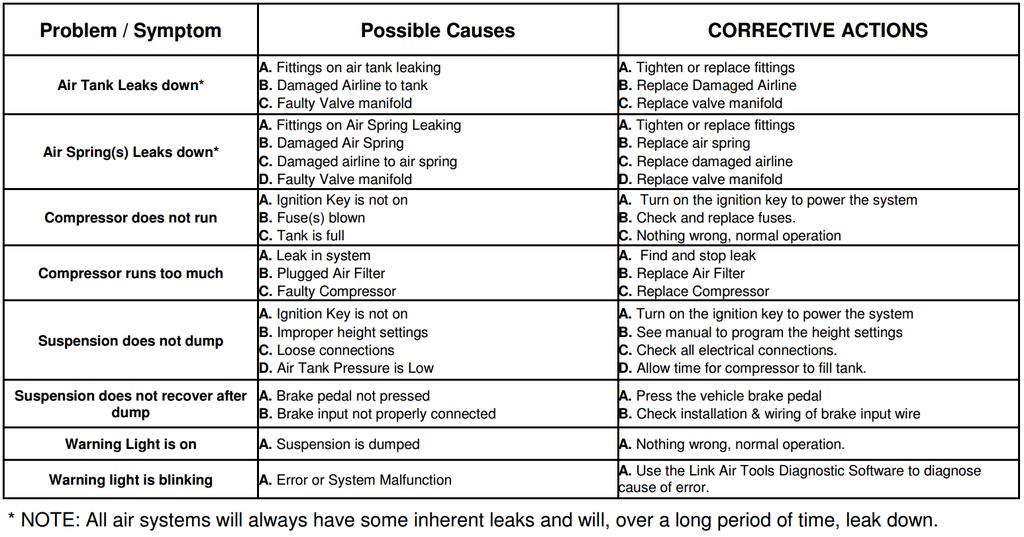
7 5. TROUBLESHOOTING 7
8 2A Fuse in Control Panel 6. FUSES o If your vehicle is equipped with the Link 800M1074 control panel, there is a 2A fuse located in that control panel between the ignition power and the rest of the air kit electrical system. o If your vehicle is NOT equipped with the Link 800M1074 control panel, consult the original suspension installer for control panel details and fuse locations. 50A Power Fuse o A 50A fuse is installed between the battery +12V supply power and the Air Kit Vehicle harness. o This fuse is often near the battery, but can be located elsewhere as determined by the air kit and suspension installer. 8
 30 7")

9 ULTRARIDE - 800M1400 ELECTRONIC AIR CONTROL KIT PARTS LIST ITEM PART NUMBER DESCRIPTION QTY INTAKE AIR FILTER KIT POWER HARNESS COMMUNICATION HARNESS 3 800M1402 AIR CONTROL UNIT RELAY ECU AIRLINE-NYLON, 3/8 BULK (FEET) CORRUGATED LOOM, 3/8 BULK (FEET) COMPRESSOR VALVE MANIFOLD 1 SOLD SEPERATELY 1 800M1071 SENSOR KIT, FORD M1072 SENSOR KIT, RAM M1401 MOUNT KIT M1074 CONTROL PANEL AUTOMATIC DRAIN VALVE KIT HEATED AUTOMATIC DRAIN VALVE KIT 1 9
10 ULTRARIDE - 800M1074 OPTIONAL CONTROL PANEL PARTS LIST ITEM PART NUMBER DESCRIPTION QTY C07 NO. 8 X.438 PHIL-PAN SHEET BOX(4.25 X 2.5 X 8.00) LABEL-AIR CONTROL, ULTRARIDE SWITCH-ROCKER FUSE HOLDER,PANEL STYLE HARNESS-CONTROL, ULTRARIDE LIGHT-LED, 12V AMP FUSE PANEL-MOUNT, SWITCH 1 10
11 CHASSIS INTEGRATION WIRING HARNESS ELECTRICAL SCHEMATIC 11

12 INTERNAL WIRING HARNESS ELECTRICAL SCHEMATIC 12
13 PNEUMATIC SCHEMATIC 13
 722-4874 http://www.linkmfg.")
14 AIR KIT CONTROL PANEL ELECTRICAL SCHEMATIC Link Mfg. Ltd th St. NE Sioux Center, IA USA (712)
Please Read this manual before operating your UltraRide Suspension, and keep it for future reference.
 OWNER S MANUAL Model # 800M1300 Lot/Serial # Questions? Contact this Professional Installer : Company : Phone : ELECTRONIC AIR CONTROL KIT Installer : Date : MN-769 80003011 MAR 20, 2013 Please Read this
OWNERS MANUAL GM C4500/C5500 4X2 REAR STABILIZER BAR KIT 2006-NEWER MODELS. For Installation with 8M and 8M UltraRide Suspension
 OWNERS MANUAL GM C4500/C5500 4X2 REAR STABILIZER BAR KIT 2006-NEWER MODELS For Installation with 8M000090 and 8M000105 UltraRide Suspension Questions? Contact this Professional Installer : Link Kit Part
OWNERS MANUAL. GMC C K AND 19K GVW CHASSIS CAB 2004-NEWER MODELS (Link Part No. 8M000050) PROUDLY INSTALLED BY : COMPANY : INSTALLER SIGNATURE :
 PROUDLY INSTALLED BY : COMPANY : INSTALLER SIGNATURE :") OWNERS MANUAL GMC C5500 15K AND 19K GVW CHASSIS CAB 2004-NEWER MODELS (Link Part No. 8M000050) Link Mfg. Ltd. 223 15th St. N.E. Sioux Center, IA USA 51250-2120 (712) 722-4868 Fax (712) 722-4779 QUESTIONS?
OWNERS MANUAL GMC C5500 15K AND 19K GVW CHASSIS CAB 2004-NEWER MODELS (Link Part No. 8M000050) Link Mfg. Ltd. 223 15th St. N.E. Sioux Center, IA USA 51250-2120 (712) 722-4868 Fax (712) 722-4779 QUESTIONS?
INSTALLATION INSTRUCTIONS
 INSTALLATION INSTRUCTIONS GMT 560 (4500/5500) CREW CAB (2351A000) Link Mfg. Ltd. 223 15th St. N.E. Sioux Center, IA USA 51250-2120 The CABMATE MODEL 2351A000 fits the 2003 and later GM 4500 / 5500 crew
OWNERS MANUAL GM C4500/C5500 DANA MODEL S135 REAR AXLE 2003-NEWER MODELS LINK MFG. PART NO. 8M PROUDLY INSTALLED BY : COMPANY :
 OWNERS MANUAL GM C4500/C5500 DANA MODEL S135 REAR AXLE 2003-NEWER MODELS LINK MFG. PART NO. 8M000030 Link Mfg. Ltd. 223 15th St. N.E. Sioux Center, IA USA 51250-2120 (712) 722-4874 Fax (712) 722-4876 QUESTIONS?
OWNERS MANUAL GM C4500/C5500 4X4 DANA MODEL S135 REAR AXLE 2005-NEWER MODELS LINK MFG. PART NO. 8M PROUDLY INSTALLED BY : COMPANY :
 OWNERS MANUAL GM C4500/C5500 4X4 DANA MODEL S135 REAR AXLE 2005-NEWER MODELS LINK MFG. PART NO. 8M000060 Link Mfg. Ltd. 223 15th St. N.E. Sioux Center, IA USA 51250-2120 (712) 722-4874 Fax (712) 722-4876
Light Duty Electronic Air Command
 2491 PSI BAR Light Duty Electronic Air Command INSTALLATION INSTRUCTIONS Congratulations on your purchase of a Light Duty Electronic Air Command kit. This kit was designed to provide inflation control
Kit INSTALLATION GUIDE. 160 psi Air Shock Controller
 Kit 25804 160 psi Air Shock Controller Cover image may not depict actual kit. MN-203 (121107) ECR 7119 INSTALLATION GUIDE For maximum effectiveness and safety, please read these instructions completely
FORD F350 SUPER DUTY CHASSIS CABS MODELS
 OWNERS MANUAL FORD F350 SUPER DUTY CHASSIS CABS 1999-2007 MODELS w/ Dana 80 Axle Link Part Nos. 8M000063 : Base Suspension 8M000064 : 4X2 Axle Kit 8M000065 : 4X4 Axle Kit Questions? Contact this Professional
Heavy Duty Air Command
 2097 / 2227 Heavy Duty Air Command INSTALLATION INSTRUCTIONS Congratulations on your purchase of a new Air Command kit. This kit was designed to provide inflation control of your air helper springs. This
KLM and up Ford F-53 Chassis Motorhome Front Installation Instructions
 KLM15757 2006 and up Ford F-53 Chassis Motorhome Front Installation Instructions Installation 1. Place the coach on a level concrete surface. 2. Place a jack under each side of the frame just behind the
OWNER S GUIDE 8A DURALIFT II 13,200 LB. CAPACITY. Link Mfg. Ltd th St. N.E. Sioux Center, IA USA
 OWNER S GUIDE 8A000715 DURALIFT II 13,200 LB. CAPACITY Link Mfg. Ltd. 223 15th St. N.E. Sioux Center, IA USA 51250-2120 www.linkmfg.com QUESTIONS? CALL CUSTOMER SERVICE 1-800-222-6283 DEALER / INSTALLER:
HYDRAULIC LEVELING SYSTEMS OPERATIONS MANUAL (For systems with touch pad part number , , , , or no number at all)
") HYDRAULIC LEVELING SYSTEMS OPERATIONS MANUAL (For systems with touch pad part number 500089, 500105, 500210, 500456, 500535 or no number at all) Visit us on the web at www.powergearus.com 82-L0040-01 Rev.
HYDRAULIC LEVELING SYSTEMS OPERATIONS MANUAL (For systems with touch pad part number 500089, 500105, 500210, 500456, 500535 or no number at all) Visit us on the web at www.powergearus.com 82-L0040-01 Rev.
HPx-JDx3-xx HARNESS INSTALLATION
 HPx-JDx3-xx HARNESS INSTALLATION Conversion Manual 09040106b HEADSIGHT.COM 574.546.5022 About Headsight Headsight Contact Info Headsight, Inc. 4845 3B Road Bremen, IN 46506 Phone: 574-546-5022 Fax: 574-546-5760
Owner s Manual and Warranty Information
 RAVE STAIR LIFT Owner s Manual and Warranty Information IMPORTANT! YOU MUST READ AND UNDERSTAND THIS ENTIRE MANUAL BE READ AND UNDERSTOOD BEFORE ATTEMPTING TO OPERATE THIS LIFT. IF THERE IS ANYTHING IN
LEXION SINGLE FUNCTION HYDRAULIC VALVE KIT
 LEXION SINGLE FUNCTION HYDRAULIC VALVE KIT Conversion Manual 09062010b HEADSIGHT.COM 574.546.5022 About Headsight Headsight Contact Info Headsight, Inc. 4845 3B Road Bremen, IN 46506 Phone: 574-546-5022
AIR CONTROL ACCESSORY KIT
 RAPID RESPONSE SYSTEM 2283 AIR CONTROL ACCESSORY KIT INSTALLATION INSTRUCTIONS Congratulations on your purchase of a new Air Control Accessory Kit. This kit was designed to provide inflation control of
Owner s Manual Supplement. Liquefied Petroleum Gas (LPG) Fuel System for 1998 GM Medium Duty Chassis (C-60/C-70) with 6.0L and 7.
 Fuel System for 1998 GM Medium Duty Chassis (C-60/C-70) with 6.0L and 7.") Owner s Manual Supplement Liquefied Petroleum Gas (LPG) Fuel System for 1998 GM Medium Duty Chassis (C-60/C-70) with 6.0L and 7.0L V8 OWNERS MANUAL SUPPLEMENT Table of Contents Refueling Your Vehicle...1
Owner s Manual Supplement Liquefied Petroleum Gas (LPG) Fuel System for 1998 GM Medium Duty Chassis (C-60/C-70) with 6.0L and 7.0L V8 OWNERS MANUAL SUPPLEMENT Table of Contents Refueling Your Vehicle...1
Operator s Manual. Automatic Electric Jack Leveling. The leveling system shall only be operated under the following conditions:
 Operator s Manual with Automatic Leveling Touchpad #140-1226 Control Box #140-1224 co Copyright PowerGear 1/07 #82-L0368 Rev. 0D Contents Before You Level Your Coach 1 Caution 1 Leveling System Operating
IMPORTANT! 09 to Current Straight Up Electric Billet Center Stand. Dealer and/or Customer must complete the following items: Center Stand Checklist
 IMPORTANT! 09 to Current Straight Up Electric Billet Center Stand Dealer and/or Customer must complete the following items: Center Stand Checklist 1. Complete the Measurement Guide 2. Read the Operation
Kit INSTALLATION GUIDE. For maximum effectiveness and safety, please read these instructions completely before proceeding with installation.
 Kit 25690 MN-369 (111512) ECR 8349 INSTALLATION GUIDE For maximum effectiveness and safety, please read these instructions completely before proceeding with installation. Failure to read these instructions
FLEETWOOD TRAVEL TRAILER SLIDEOUT SYSTEM OWNER S MANUAL
 FLEETWOOD TRAVEL TRAILER SLIDEOUT SYSTEM OWNER S MANUAL 82-S0150-01 REV. 1 April, 2002 TABLE OF CONTENTS PAGE # OPERATIONS MANUAL... 1 1. SYSTEM DESCRIPTION... 1 1.1 MAJOR COMPONENTS... 1 2. HOW TO OPERATE
INSTALLATION INSTRUCTIONS PARTS LIST INSTALLATION INSTRUCTIONS AIR CONTROL KIT (800A0168 OR 800A0169)
") INSTALLATION INSTRUCTIONS INSTALLATION INSTRUCTIONS PARTS LIST AIR CONTROL KIT (800A0168 OR 800A0169) Link mfg. Ltd. 223 15th St. N.E. Sioux Center, IA USA 51250-2120 (712) 722-4874 Fax (712) 722-4876
INSTALLATION INSTRUCTIONS INSTALLATION INSTRUCTIONS PARTS LIST AIR CONTROL KIT (800A0168 OR 800A0169) Link mfg. Ltd. 223 15th St. N.E. Sioux Center, IA USA 51250-2120 (712) 722-4874 Fax (712) 722-4876
Emission Control Warranty Statement
 Emission Control Warranty Statement Gas engine-generator sets MTU 10V0068 GS75 MTU 10V0068 GS100 MTU 10V0068 GS125 Built in North America MS65038/00E Table of Contents Table of Contents 1 Federal Emission
INSTRUCTIONS PARTS LIST This manual contains important warnings and information. READ AND RETAIN FOR REFERENCE
 INSTRUCTIONS PARTS LIST 308 493 This manual contains important warnings and information. READ AND RETAIN FOR REFERENCE Rev. A Second Gun Hose Kit 100 psi (6.9 bar) Maximum Working Pressure These kits include
60 PSI Boost Gauge. For Product Numbers: MT-DV01_60, MT-WDV01_60
 60 PSI Boost Gauge For Product Numbers: MT-DV01_60, MT-WDV01_60 Red: 12v Constant (un-switched) Source (+) Orange: 12v Dimmer (switched) Source (+) (optional) White: 12v Ignition (switched) Source (+)
Emission Control System Warranty Statement
 Emission Control System Warranty Statement Marine and industrial diesel engines Supplement to Operator s Manual (USA) Marine engines This Emission Control System Warranty Statement applies only to engines
P N # C APPLICATION:
 P N # C 1 8 0 5 6 APPLICATION: DODGE RAM 4WD VEHICLES Pacbrake s 4WD 2 Wheel Low Kit allows the vehicle operator to engage the transfer case into 4WD low range without engaging the front wheel drive, allowing
Ride Rite Warranty Evaluation Guide
 What s covered The Ride-Rite kits, components, and accessories are warranted against defects in workmanship and materials*. What s not covered This warranty does not cover service or labor charges, freight
SOLAR DASH CHARGING SYSTEM USER GUIDE
 SOLAR DASH CHARGING SYSTEM Doc 1.01 INST049 INSTALLATION STEP 1 Place 20 watt solar panel in the dash of the vehicle facing up. Note: For ideal results position the vehicle in a manner in which the solar
INSTALLATION GUIDE. Universal System for Zero Turn Mowers
 INSTALLATION GUIDE Universal System for Zero Turn Mowers Table of Contents General Information 1 Important Notice to Purchaser 2 Specifications 2 Intended Usage 2 Important Information 3 General Safety
WirelessAIR Advanced Integrated Remote
 Advanced Integrated Remote Kit 72000 Automatic Leveling Digital On-Board Compressor System MN-772 (011108) APQP 1313-31 INSTALLATION GUIDE For maximum effectiveness and safety, please read these instructions
Part# W HID Flood Light Kit
 400 W. Artesia Blvd. Compton, CA 90220 Fax: (310) 747-3912 Ph: 1-800-776-0767 E-Mail: info@procompusa.com Website: www.procompusa.com Revised PRO COMP SUSPENSION Part# 9640 4 35W HID Flood Light Kit 9670
Xtreme Air Command. Step 1 Prepare the components. Step 2 Select a mounting location. Parts list
 2549 60 90 400 600 30 200 120 800 psi 1000 kpa PSI 0 150 Xtreme Air Command Installation instructions Congratulations on your purchase of a new Xtreme Air Command kit. This kit was designed to provide
OPERATORS MANUAL for MANUAL RV LEVELING SYSTEM. Comment [KO1]:
![OPERATORS MANUAL for MANUAL RV LEVELING SYSTEM. Comment [KO1]:](/thumbs/88/117097014.jpg "OPERATORS MANUAL for MANUAL RV LEVELING SYSTEM. Comment [KO1]:") OPERATORS MANUAL for MANUAL RV LEVELING SYSTEM Comment [KO1]: 82 L0356 Rev. 0 June 2003 TABLE OF CONTENTS OPERATION AND MAINTENANCE...1 OPERATION CAUTION NOTES...1 BEFORE YOU OPERATE THE SYSTEM...2 SELECTING
OPERATORS MANUAL for MANUAL RV LEVELING SYSTEM Comment [KO1]: 82 L0356 Rev. 0 June 2003 TABLE OF CONTENTS OPERATION AND MAINTENANCE...1 OPERATION CAUTION NOTES...1 BEFORE YOU OPERATE THE SYSTEM...2 SELECTING
Pressure Roller with 24-inch Fixed Extension - For application of architectural paints and coatings -
 Instructions Important Safety Instructions Read all warnings and instructions in this manual. Save these instructions. 311082D Pressure Roller with 24-inch Fixed Extension - For application of architectural
Installation Instructions
 85-3414 rev. 02 11-09 Installation Instructions Thank you for purchasing this anti-sway bar kit. Please read through these instructions before installation. Rear Anti-Sway Bar Kit for the Monaco Diplomat
Residential Platform Lifts RPL400 / RPL600 Owner s Manual and Warranty Information
 Residential Platform Lifts RPL400 / RPL600 Owner s Manual and Warranty Information IMPORTANT: Read and understand this entire Owner s Manual before attempting to operate this Stair Lift. If you do not
Model , Series A 9 in. (23 cm) roller frame with 45 angle and 12 in. reach 1/2 in. (13 mm) nap roller cover
 roller frame with 45 angle and 12 in. reach 1/2 in. (13 mm) nap roller cover") Operating Instructions 309899 Rev. A This manual contains important warnings and information. READ AND KEEP FOR REFERENCE. INSTRUCTIONS Manufactured by Model 246818, Series A 9 in. (23 cm) roller frame
Operating Instructions 309899 Rev. A This manual contains important warnings and information. READ AND KEEP FOR REFERENCE. INSTRUCTIONS Manufactured by Model 246818, Series A 9 in. (23 cm) roller frame
A/C PRESSURE MONITOR INSTALLATION INSTRUCTIONS SYSTEM OPERATION GREEN INDICATOR LIGHT
 A/C PRESSURE MONITOR INSTALLATION INSTRUCTIONS Do not attempt to clean or inspect anything while the engine is running. Cleaning and inspection must be done by a certified mechanic. All A/C service must
Installation Instructions
 85-3910 rev. 03 01-18 Installation Instructions Thank you for purchasing the antisway bar kit. Please read through these instructions before installation. Rear Anti-Sway Bar Kit for Ford F-250/F-350 part
CLEAN ROOM DEVICES, LLC "WHERE TUBING AND FITTINGS COME TOGETHER"
 CLEAN ROOM DEVICES, LLC "WHERE TUBING AND FITTINGS COME TOGETHER" CRD400 Fitting Inserter OPERATIONS MANUAL VERSION 3.1 LAST EDITED 03.08.11 DOCUMENT NUMBER 001 cleanroomdevices.com 1 Table of Contents
CRD400 Fitting Inserter OPERATIONS MANUAL
 CRD400 Fitting Inserter OPERATIONS MANUAL ORIGINAL INSTRUCTIONS VERSION 3.4 LAST EDITED 01.07.2019 www.cleanroomdevices.com 1 Table of Contents Title Page.. 1 Table of Contents... 2 1.0 General Product
Kit INSTALLATION GUIDE. Single Gauge Controller
 Kit 25655 Single Gauge Controller Cover image may not depict actual kit. MN-342 (031107) ECR 7119 INSTALLATION GUIDE For maximum effectiveness and safety, please read these instructions completely before
Kit INSTALLATION GUIDE. 5 psi Low Pressure Sensor (Single Gauge)
") Kit 25592 5 psi Low Pressure Sensor (Single Gauge) MN-333 (141404) ECR 7953 INSTALLATION GUIDE For maximum effectiveness and safety, please read these instructions completely before proceeding with installation.
Kit 25592 5 psi Low Pressure Sensor (Single Gauge) MN-333 (141404) ECR 7953 INSTALLATION GUIDE For maximum effectiveness and safety, please read these instructions completely before proceeding with installation.
STANDARD WARRANTY TERMS *
 ATK NORTH AMERICA S PRODUCT WARRANTY POLICY APRIL 2012 LIMITED WARRANTY ATK will repair or replace, free of charge, any part(s) of the product that is defective in material or workmanship or both. Transportation
AGCO Conversion Manual a HEADSIGHT.COM
 AGCO 3300 Conversion Manual 09040404a HEADSIGHT.COM 574.546.5022 About Headsight Headsight Contact Info Headsight, Inc. 4845 3B Road Bremen, IN 46506 Phone: 574-546-5022 Fax: 574-546-5760 Email: info@headsight.com
PVI 1800/PVI Residential/Commercial Grid-Tied Photovoltaic Inverter WARRANTY MANUAL. Subject to Change REV , Solectria Renewables
 PVI 1800/PVI 2500 WARRANTY MANUAL Residential/Commercial Grid-Tied Photovoltaic Inverter 2009, Solectria Renewables Subject to Change REV 10.09 1 Product Warranty & RMA Policy 1.1 Warranty Policy The Solectria
EMISSION COMPONENT DEFECT WARRANTY PERIOD
 FEDERAL EMISSIONS COMPONENT DEFECT EMISSIONS COMPONENT DEFECT COVERAGE - This emission warranty is applicable in all States, except the State of California. Fuji Heavy Industries Ltd. and Robin America
CAPACITOR ACTUATED PORTABLE STARTER CAPS USER GUIDE. INST048 Doc 3.01
 CAPACITOR ACTUATED PORTABLE STARTER CAPS USER GUIDE INST048 Doc 3.01 CONTENTS General Information...2 Charts...3 Before First Use...4 Safety Requirements...5 What to Expect from the CAPS...5 CAPS Diagram...6
Manual Addendum. ULTRARIDE Manual Addendum For BARKSDALE Height Control Valves
 Manual Addendum ULTRARIDE Manual Addendum For BARKSDALE Height Control Valves This document contains important information on changes to the UltraRide Suspension system not yet reflected in the Installation
ActuLink ABS Module - ABS-MOD-400
 Installation Instructions ActuLink ABS Module - ABS-MOD-400 For more information on the installation and operation of Tuson s towable ABS system, consult the installation and operations manuals for the
POWER GEAR SLIDE-OUT MANUAL
 POWER GEAR SLIDE-OUT MANUAL Operation Guide FLUSH FLOOR SLIDE-OUT SYSTEM FOR AMERICAN COACH PRODUCTS 82-S0220-01 Rev. 1 AMERICAN COACH SLIDE-OUT MANUAL FLUSH FLOOR SYSTEM TABLE OF CONTENTS SECTION PAGE
Installation Instructions
 85-3214 rev. 07 03-11 Installation Instructions Thank you for purchasing this anti-sway bar kit. Please read through these instructions before installation. Rear Anti-Sway Bar Kit Freightliner FL Series
PARTS MANUAL FOR TWO STAGE AIR COMPRESSOR
 PARTS MANUAL FOR TWO STAGE AIR COMPRESSOR SPECIFICATION CHART Model No. Horsepower Voltage-Single Phase Minimum Branch Circuit Requirement *Fuse Type Air Tank Capacity Approximate Cut-in Pressure Approximate
Back Up Steering System Honda Odyssey
 Providing Mobility for the Physically Challenged Since 1952 Back Up Steering System 2008-2009 Honda Odyssey Installation Manual and Owner s Guide 37 Daniel Rd. West, Fairfield, NJ 07004-2521 973-808-9709
Kit PSI Air Shock Controller
 Kit 25804 160 PSI Air Shock Controller MN-203 (141606) ECR 8612 INSTALLATION GUIDE For maximum effectiveness and safety, please read these instructions completely before proceeding with installation. Failure
DRAGO. Corn Header Manual f HEADSIGHT.COM
 DRAGO Corn Header Manual 09020801f HEADSIGHT.COM 574.546.5022 About Headsight Headsight Contact Info Headsight, Inc. 4845 3B Road Bremen, IN 46506 Phone: 574-546-5022 Fax: 574-546-5760 Email: info@headsight.com
Installation Instructions
 Installation Instructions Thank you very much for purchasing PIAA product. Please read this entire manual before installation and use of this product. For Installers Please give this Installation Manual
LifeGuardLift. LifeGuard Power Lift Model #100287A OWNERS MANUAL. Rev: 2/14/11
 LifeGuardLift OWNERS MANUAL LifeGuard Power Lift Model #100287A Rev: 2/14/11 Table of Contents 1. ASSEMBLY INSTRUCTIONS A. Lift Assembly B. Setup C. Disassembly 2. CONTROL SYSTEM A. Batteries B. Battery
Kit INSTALLATION GUIDE. For maximum effectiveness and safety, please read these instructions completely before proceeding with installation.
 Kit 25801 MN-208 (121506) ECR 8243 INSTALLATION GUIDE For maximum effectiveness and safety, please read these instructions completely before proceeding with installation. Failure to read these instructions
NAPA IRONCLAD PRODUCT WARRANTY POLICY
 NAPA IRONCLAD PRODUCT WARRANTY POLICY LIMITED WARRANTY NAPA Ironclad will repair or replace, free of charge, any part(s) of the product that is defective in material or workmanship or both. Transportation
FAST-FLASH Programmer Ford 6.0L Powerstroke Turbo Diesel (2003 and Newer)
") INSTRUCTIONS FAST-FLASH Programmer Ford 6.0L Powerstroke Turbo Diesel (2003 and Newer) Thank you for your purchase of electronic tuning products; we are proud to be your manufacturer of choice! The FAST-FLASH
INSTRUCTIONS FAST-FLASH Programmer Ford 6.0L Powerstroke Turbo Diesel (2003 and Newer) Thank you for your purchase of electronic tuning products; we are proud to be your manufacturer of choice! The FAST-FLASH
SELECT/DIRECT DEMO BOX USER GUIDE. INST164 Doc 1.00
 SELECT/DIRECT DEMO BOX USER GUIDE INST164 Doc 1.00 CONTENTS Using the Demo Box...2 Direct Dual Pole (Stinger) Demonstration...5 Select Dual Pole, Reefer, or Aux Demonstration...6 Switch Board Callouts...7
Liftmoore, Inc. SERVICE BODY PRODUCT LIST. Contact Liftmoore for Special Applications This list is comprised of our Standard Units only.
 Liftmoore, Inc. SERVICE BODY PRODUCT LIST Contact Liftmoore for Special Applications This list is comprised of our Standard Units only. Public Effective Index Page 1 Terms Page 2 Crane Ready Service Body
Warranty Information North America
 Publication No. 47705137 January 1, 2014 Warranty Information North America Industrial and Power Generation Power Systems Parts and Accessories Includes: Power Systems Warranty Statement Parts and Accessories
Single Leg AM / CM 20, 24 and 30. Installation
 1-800-846-9659 www.equalizersystems.com Installation and Operation Guide January 2011 Single Leg AM / CM 20, 24 and 30 Installation Tools Required for Installation Ratchet, Sockets and Wrench Set Wire
Pro Shot Grease Dispense Valve
 Instructions Parts List Pro Shot Grease Dispense Valve 309032J For high pressure grease dispense. 8000 psi (55 MPa, 552 bar) Maximum Working Pressure Model No. 242055, Series B, 1/4 npt Fluid Inlet Model
PVI 60KW, PVI 82KW, PVI 95KW
 PVI 60KW PVI 82KW PVI 95KW WARRANTY MANUAL Commercial, Grid-Tied Photovoltaic Inverters 2008, Solectria Renewables LLC Subject to Change DOC-020099 rev 024 1 1 Product Warranty & RMA Policy Warranty Policy
Installation Instructions
 85-4592 rev. 08 02-18 Installation Instructions Thank you for purchasing our sway bar kit. Please read through these instructions before installation. Auxiliary Rear Anti-Sway Bar Kit for Ford F53 part
SELECT -24 INSTALLATION GUIDE. INST036 Doc 2.02
 SELECT -24 INSTALLATION GUIDE INST036 Doc 2.02 CONTENTS General Information...2 Select-24 Diagram...3 Mounting the Select Controller...4 Dual Pole Nosebox Installation...5 Aux Harness Installation...6
Installation Instructions
 85-3207 rev. 03 05-06 Installation Instructions Thank you for purchasing this anti-sway bar kit. Please read through these instructions before installation. Rear Anti-Sway Bar Kit for the Freightliner
AGCO. Corn Header Manual d HEADSIGHT.COM
 AGCO Corn Header Manual 09020401d HEADSIGHT.COM 574.546.5022 About Headsight Headsight Contact Info Headsight, Inc. 4845 3B Road Bremen, IN 46506 Phone: 574-546-5022 Fax: 574-546-5760 Email: info@headsight.com
Flow Control Valve Instruction Manual
 CVM3-M0_042018 MODEL: Flow Control Valve Instruction Manual CVM3 & CVMS3 SFA Companies 10939 N. Pomona Ave. Kansas City, MO 64153 Tel: 888-332-6419 * Fax: 816-448-2142 E-mail: sales@bvahydraulics.com Website:
FOLD CONTROL FOR 600FC
 FOLD CONTROL FOR 600FC Conversion Manual 09040122b HEADSIGHT.COM 574.546.5022 About Headsight Headsight Contact Info Headsight, Inc. 4845 3B Road Bremen, IN 46506 Phone: 574-546-5022 Fax: 574-546-5760
LKQ LIMITED WARRANTY FOR REMANUFACTURED ENGINES
 LKQ LIMITED WARRANTY FOR REMANUFACTURED ENGINES LKQ Corporation and its subsidiaries distributes a broad range of new, recycled, remanufactured and reconditioned automotive and truck replacement products
Operators Manual. Recirculating Chiller /06/08
 Operators Manual Recirculating Chiller 110-197 11/06/08 Table of Contents Section 1. General Information 1.1 Warranty 1.2 Unpacking 1.3 Package Contents 1.4 Description of the Recirculating Chiller 1.5
PIAA Multi-Fit 005/1100X Light Bracket Kits
 ENGLISH PIAA Multi-Fit 005/1100X Light Bracket Kits Thank you for your purchase. Please read all the instructions before beginning.! WARNING Lighting laws vary state to state, check your local laws before
Residential Platform Lifts RPL400 / RPL600 Owner s Manual and Warranty Information
 Residential Platform Lifts RPL400 / RPL600 Owner s Manual and Warranty Information IMPORTANT: Read and understand this entire Owner s Manual before attempting to operate this Stair Lift. If you do not
Table of Contents. Technical Information Warning Statement
 Table of Contents Technical Information-----------------------------------1 Warning Statement--------------------------------------2 Read Before Riding-------------------------------------3 List of Parts-----------------------------------------------4
DIGIGAUGE P R E S S U R E D I S P L A Y S Y S T E M I N S T R U C T I O N M A N U A L
 DIGIGAUGE P R E S S U R E D I S P L A Y S Y S T E M I N S T R U C T I O N M A N U A L Thank you for purchasing DigiGauge by ZAETECH Disclaimer DigiGauge is for show and off road use only. By using this
4" ENVIRONMENTAL E-SERIES PUMPS OWNER'S MANUAL. DANGER warns about hazards that will cause. WARNING warns about hazards that can cause
 4" ENVIRONMENTAL E-SERIES PUMPS OWNER'S MANUAL BEFORE INSTALLING PUMP, BE SURE TO READ THIS OWNER S MANUAL CAREFULLY. CAUTION Fill pump with water before starting or pump will be damaged. The motor on
DISCONTINUED VERSION Parts listed in this catalog may no longer be available. ILLUSTRATED PARTS CATALOG
 BUNN WL WARMER DISCONTINUED VERSION Parts listed in this catalog may no longer be available. FRONT REAR ILLUSTRATED PARTS CATALOG Designs, materials, weights, specifications, and dimensions for equipment
Manifold w/ Needle Valve Instruction Manual
 MODELS: MFC2 & MFC4 Manifold w/ Needle Valve Instruction Manual SFA Companies 10939 N. Pomona Ave. Kansas City, MO 64153 Tel: 888-332-6419 - Fax: 816-448-2142 E-mail: sales@bvahydraulics.com Website: www.bvahydraulics.com
Owner s Manual GLASSLINED PUMP TANK
 Owner s Manual GLASSLINED PUMP TANK ANSI/NSF 61 Annex G Thank You for purchasing a pump tank. Properly installed and maintained, it should give you years of trouble free service. If you should decide that
equalizersystems.com. Installation and Operation Guide October Revision- November 2016
 1-800-846-9659 equalizersystems.com Installation and Operation Guide October 2010 Revision- November 2016 AJ Series Single Leg Hydraulic Jack: 7,500# Capacity Installation Tools Required for Installation
GERINGHOFF. Corn Header Manual f HEADSIGHT.COM
 GERINGHOFF Corn Header Manual 09020701f HEADSIGHT.COM 574.546.5022 About Headsight Headsight Contact Info Headsight, Inc. 4845 3B Road Bremen, IN 46506 Phone: 574-546-5022 Fax: 574-546-5760 Email: info@headsight.com
EMISSION WARRANTIES MS65022/02E
 EMISSION WARRANTIES MS65022/02E Printed in Germany 2015 Copyright MTU Friedrichshafen GmbH This Publication is protected by copyright and may not be used in any way whether in whole or in part without
Model Railroad Circuit Breaker (CB-1)
") Model Railroad Circuit Breaker (CB-1) User Manual Ring Engineering Inc. (219) 322-0279 www.ringengineering.com Revision 1.11 Copyright 2018 Ring Engineering Inc. All rights reserved. Introduction Thank
Model Railroad Circuit Breaker (CB-1) User Manual Ring Engineering Inc. (219) 322-0279 www.ringengineering.com Revision 1.11 Copyright 2018 Ring Engineering Inc. All rights reserved. Introduction Thank
4101 / 4102 READ INSTALLATION INSTRUCTIONS IN ITS ENTIRETY BEFORE INSTALLING YOUR COIL-RITE KIT PARTS LIST OPERATING PRESSURES. Figure A DESCRIPTION
 4101 / 4102 READ INSTALLATION INSTRUCTIONS IN ITS ENTIRETY BEFORE INSTALLING YOUR COIL-RITE KIT Figure A PARTS LIST DESCRIPTION QTY. AIR SPRINGS 2 UPPER SUPPORTS 2 LOWER SUPPORTS (BOLT) 2 LOWER SUPPORTS
Parts Catalog Nautilus & Nautilus CE Rider Scrubber/Sweeper Models: Diesel, Gasoline, & LPG
 Parts Catalog Nautilus & Nautilus CE Rider Scrubber/Sweeper Models: Diesel, Gasoline, & LPG PowerBoss, Minuteman International, Inc. A Member of the Hako Group #988749 Rev. C 08/15 PREFACE PREFACE Thank
INSTALLATION INSTRUCTION & OWNER S MANUAL
 CS-2500 & CS-2500P Water Filtration System INSTALLATION INSTRUCTION & OWNER S MANUAL Ver 1.2 All Rights Reserved APEC Water Systems Please keep this Owner s Manual for future reference. It contains useful
Superchips Model 2704 MAX MicroTuner GM Trucks with 6.6L Duramax Diesel Engines Vehicle Programming Instructions
 Page 1 of 12 Form 0137D 11/30/2004 Superchips Inc. Superchips Model 2704 MAX MicroTuner 2004-2005 GM Trucks with 6.6L Duramax Diesel Engines Vehicle Programming Instructions PLEASE READ THIS ENTIRE INSTRUCTION
Liftmoore, Inc. SERVICE BODY PRODUCT LISTING. Contact Liftmoore for Special Applications This list is comprised of our Standard Units only.
 Liftmoore, Inc. SERVICE BODY PRODUCT LISTING Contact Liftmoore for Special Applications This list is comprised of our Standard Units only. PUBLIC Effective Index Page 1 Terms Page 2 Crane Ready Service
Installation Instructions
 85-4209 rev. 05 11-18 Installation Instructions Thank you for purchasing this anti-sway bar kit. Please read through these instructions before installation. Factory Replacement Anti-Sway Bar Kit part #1129-135
Thermaltake Warranty / Support Information
 Thermaltake Warranty / Support Information Technical Support Thermaltake is committed to providing the highest quality, most reliable products for our valued customer. There are several ways you may contact
Installation Instructions
 85-3209 rev. 07 03-11 Installation Instructions Thank you for purchasing this anti-sway bar kit. Please read through these instructions before installation. Front Anti-Sway Bar Kit for Workhorse W22, Holiday
GEARHEAD LIMITED WARRANTY FOR REMANUFACTURED ENGINES
 GEARHEAD LIMITED WARRANTY FOR REMANUFACTURED ENGINES GEARHEAD Engines distributes a broad range of new, recycled, remanufactured and reconditioned automotive and truck replacement products. Our remanufactured
The function of this Dynamic Active Probe has divided into three preferences on the screen main Menus:
 1.0 Introduction: This probe is designed to provide an additional help to automotive technicians in trouble shooting of electrical circuits problems in the car. Apart from using the normal multi tester,
USER MANUAL. NEMA 48C Flange Mounted, Enclosed, Clutch Brake. FMCBE Model 500 FORM NO. L A (i)
") USER MANUAL NEMA 48C Flange Mounted, Enclosed, Clutch Brake FMCBE Model 500 (i) In accordance with Nexen s established policy of constant product improvement, the specifications contained in this manual
USER MANUAL NEMA 48C Flange Mounted, Enclosed, Clutch Brake FMCBE Model 500 (i) In accordance with Nexen s established policy of constant product improvement, the specifications contained in this manual