Compact LTC Oil Filtration System Manual
|
|
|
- Laurence Griffin
- 6 years ago
- Views:
Transcription


1 INSTRUCTION MANUAL Compact LTC Oil Filtration System Manual COMPACT LTC OFS-MANUAL 1.4 READ AND UNDERSTAND THIS MANUAL PRIOR TO OPERATING OR SERVICING THIS PRODUCT.
2 TABLE OF CONTENTS General System Description & Specifications Pages 2 3 Control Box Features & Layout Page 4 5 Filter, Pump & Motor Description Page 6 Electrical Installation & Standard Alarm Wiring Page 7 8 External Piping Page 9 Initial Pump Priming Page General Operation, Timer Settings & Cold Temperatures Pages General Maintenance & Troubleshooting Page Appendix A: General Dimensions Page 19 Appendix B: General Piping Diagrams Page Appendix C: Ladder/Point Wiring Diagrams Page Appendix D: Optional Flow & Pressure Transducers Page Appendix E: Optional Auto Run Cold System Page 27 Appendix F: Oil PCB-Free Statement Page 28 1
3 GENERAL DESCRIPTION Waukesha LTC Oil Filtration Systems have been designed to remove operating contaminants from the insulating oil of load tap changers. The removal of contaminants can help maintain the oil at the highest possible dielectric strength and minimize equipment failure and downtime. Filtering systems can be installed on existing transformers in the field or specified on new transformers. Oil filtration systems can be configured with various industry-standard filters. This instruction manual outlines the external mounting configuration, installation and operation of the various units. SYSTEM SPECIFICATIONS 1) Rugged Weatherproof Cabinet Outdoor cabinet specifically designed for the oil filtration task with integral mounting flanges and anti-condensate heating. 2) Integral Catch Sump Built-in 8 gallon catch sump to ensure the avoidance of any environmental spills. 3) Internal Systems Systems are integrated into the cabinet construction to promote a compact, smooth running design. 4) Automatic Systems Monitoring Control system, with electrical surge protection, monitors the critical system operation parameters noted below, providing for automatic shut-down and alarm relays that allow for customer monitoring: a. High Pressure System monitors the oil pressure and provides for automatic system shut-down if pressure exceeds 85 PSI. A 5-minute delay on start-up is included to prevent false alarm conditions. High pressure normally indicates the need for filter maintenance (set at the factory to 68 PSIG if pleated filter option is chosen). b. Low Flow System monitors the oil flow rate and provides automatic system shut-down if the flow rate drops below 0.25 GPM. A 15 second start-up delay is provided to prevent false alarm conditions. Low flow alarm can normally indicate either a need for filter maintenance or a system blockage such as a Clogged Y-Strainer (see page 14 for Y-Strainer location, page 17 for procedure). c. Leak Detection High reliability sensor located in the cabinet sump monitors for system leaks and provides for automatic system shut-down if a leak is detected. d. Customer Remote Shut-Down Relay This relay will allow the customer to remotely shut down the system by sending a 120 VAC signal from an LTC oil level sensor (or similar). 5) High Reliability Pump System a. Integral pressure activated (110 PSI) oil bypass Provides for oil recirculation in the pump to prevent system over-pressure conditions (set at the factory to 72 PSIG if pleated filter option is chosen). b. System Hoses 3000 PSI burst strength stainless steel braid covered hoses will provide years of leak-free service. c. Mechanical Seal Design Provides the maximum life for pump systems as compared to typical lipseal designs. 2
4 SYSTEM SPECIFICATIONS (continued) 6) Continuous Duty Industrial grade, totally enclosed 1/2 HP motor, with automatic reset thermal protection, rated for continuous operation. 7) Robust Filtering System accepts standard 7 x18 filter cartridges: a. Depth Filters High capacity depth filter system with SAE J1858 test score of 5 = 500 for 5 um particle size and a score of 3 = 150 for 3 um particle size. b. Pleated filters Optional 0.3 micron pleated filter element. 8) Ease of Maintenance Unique tilt-out canister system allows for ease of filter element maintenance, tool-free: a. Fast Filter change without breaking any oil line connections. b. Convenient Simple 3-way valve system for secure system isolation and addition of oil make-up. Output isolation check valve presents backflow during filter element maintenance. c. Easy Reliable, top-of-canister valve with vent tube for the venting of trapped air during startup or filter medium maintenance. Convenient bottom drain valve for use during routine maintenance. 9) Flow Indication Visible paddlewheel-style flow indicator on the output allows for quick inspection of oil quality and system operation. TOOLS FOR NORMAL MAINTENANCE The following tools will be required for normal filter change and strainer service: Filter Change No tools required. Strainer Service Open end wrench, socket or adjustable wrench capable of 1-9/32. See Maintenance Section for service procedure. For Both Suitable oil containment/disposal vessels and shop towels. CONSTRUCTION The filtration system has the pump, motor, controls and filter cartridge all located in a single enclosure. The cabinet has a built-in 8 gallon sump with automatic leak detection. The filter canister is designed for replaceable cartridges and will accept most 7 x18 oil filtration cartridges on the market today. The system is also available with an installation kit that includes all hoses, entrance tube components and fittings necessary for the oil filtration system installation. CONTROL BOX FEATURES 1) Enclosure UL Type 12 steel construction. 2) Timer Controller Field-proven, sealed and potted IC controller with field adjustable timer settings. 3) Bypass Switch Positioning this switch in the Timer Bypass mode will allow for continuous operation (24/7) of the system without changing the programming of the timer. When operating in this mode, all alarm conditions are still monitored as described above. 3
5 CONSTRUCTION: CONTROL BOX FEATURES (continued) 4) Runtime Meter This meter is located on the front cover and records total number of hours the pump has run. 5) High Pressure Alarm Relay Relay output directly wired to the customer connection terminal block to monitor the low flow and leak detection alarm. 6) Low Flow/Leak Detection Alarm Relay Relay output directly wired to the customer connection terminal block to monitor the low flow and leak detection alarm. 7) Remote Shutdown Relay Relay wired directly to the customer connection terminal block to shut down the system from a customer-supplied signal (i.e. LTC oil level gauge). 8) Indicator LED Lights Red or amber LEDs provide status indication at a glance: a. Amber System on b. Red 1 Low Flow Alarm and/or Leak Detected c. Red 2 High Pressure Alarm 4
6 CONSTRUCTION: CONTROL BOX FEATURES (continued) Figure 1 Standard Control Box with Bypass Switch and Motor Runtime Meter 5
7 CONSTRUCTION (continued) FILTER HOUSING The basic filter configuration is designed for LTC tanks up to 1000 gallons. The canister is designed to use most commercially available 7 x18 filters. The canister is rated for continuous operation at 125 PSI. The system utilizes a common replaceable filter element that is housed within a canister that swings out to allow easy cartridge replacement without oil spills or the disconnection of any lines. PUMP AND MOTOR The Waukesha oil filtration system is designed with a continuous duty rated pump with a flow rate of 1.0 GPM. The pump is equipped with a mechanical high reliability sealing system. The pump is also equipped with an integral pressure by-pass which is factory set at 110 PSI. All pumps are driven by a totally enclosed, continuous duty, thermally protected 1/2 HP motor (set at the factory to 73 PSIG if pleated filter option is chosen). The system is equipped with a pinwheel-style visual flow indicator to assist in determining proper system operation. 6

8 INSTALLATION The filter assembly may be either pad mounted or mounted on a transformer stiffener. Mounting lugs are provided to accommodate four 1/2 mounting bolts. The filter assembly weighs approximately 200 lbs. Electrical power can be brought into either side of the main cabinet and routed, via the wire duct, the main power wiring point located in the upper left hand corner of the cabinet. On most systems, power requirements are 120V AC; however, a single-phase transformer option for 240V input power is also available (see Figure 2 below). ELECTRICAL POWER CONNECTIONS 120 VAC INPUT CONNECTION 240 VAC INPUT CONNECTION NOTE: FOR USE WITH OPTIONAL TRANSFORMER NOTE: System ground pad is provided on the lower right side of the cabinet. Figure 2 120VAC and 240VAC Input Connections 7

.")
9 INSTALLATION: ELECTRICAL POWER CONNECTIONS (continued) Leak Detection & Low Flow Alarm High Pressure Alarm Remote System Shut Down Figure 3 Customer Alarm Relay Connections Pre-Wired System Connections This Side NOTE: All connections are located on the Aux Terminal strip located in the upper right hand corner of the main enclosure, behind the filter canister. For the HIGH PRESSURE alarm, connect to the terminal positions #6 and #7 on the Aux Terminal Strip. This is a NORMALLY OPEN contact from relay 63PS/AUX. This alarm will activate as the pressure increases to 85 PSIG rising (set at the factory to 68 PSIG if pleated filter option is chosen). For the LOW FLOW and/or SUMP LEAK alarms, connect to the terminal positions #7 and #8 on the Aux Terminal Strip. This is a NORMALLY OPEN contact from relay 80FS/AUX. This alarm will activate as the flow drops below 0.25 GPM. To utilize the Remote System Shutdown feature, connect to the terminal positions #11 and #12 on the Aux Terminal Strip. Applying a 120 VAC to these terminal positions will activate the relay OL/AUX and cause the system to shut down. The system will remain shut down as long as the 120 VAC is applied. When the 120 VAC signal is removed, the system will automatically initiate a normal filtering cycle. 8
10 INSTALLATION (continued) A complete flexible tube installation kid is recommended; however, the customer may also hard pipe the oil inlet and outlet from the oil filter system. These guidelines should be followed when installing the supply and return piping: 1) Plumbing from the TLC compartment to the filter should be 0.50 inside diameter or larger. 2) Do not use galvanized pipe or fittings; copper or stainless steel tubing is recommended. 3) Do not exceed six (6) elbows on the supply piping or six (6) elbows on the return piping. 4) If the total length of inlet plus outlet piping exceeds 75 feet, use 0.75 inside diameter piping or larger. 5) Inlet oil connection is 3/4 NPT female pipe thread. 6) Outlet oil connection is 3/4 NPT female pipe thread. 7) Suction and return tubes should be mounted as far from each other as possible to induce cross-flow. 8) Suction and return tubes should be mounted as close to side walls as possible. 9) The return tube should terminate at the top of the LTC tank. 10) The suction tube should draw oil from the bottom of the LTC tank and should be installed so that the tube opening is 1/2 from the bottom of the tank. 11) An anti-siphon hole must be drilled in the suction tube at 1/2 below the minimum LTC tank oil level. The anti-siphon hole prevents damage to the pumping system by preventing it from drawing air into its systems before the oil level in the LTC tank can be serviced. Drawing air into the pumping system can cause damage over time, and the air drawn in may be forced back into the LTC tank which is not a desirable situation. Moreover, in the event that the LTC oil level continues to fall, the anti-siphon hole will limit the extent of oil loss. Upon starting to draw air, the pump will shut down based on the low flow sensor. 9
11 INSTALLATION (continued) PROCEDURE FOR INITIAL PUMP PRIMING The manufacturer recommends that the pump be primed prior to start-up. This can be achieved by adding load tap changer oil directly into the oil input line by following these steps: 1) With the pump OFF, turn the 3-way valve to the horizontal position (refer to Figure 4 on page 11). 2) Place sample/prime hose in a supply of clean transformer oil (strongly recommend positioning this above the height of the 3-way valve). 3) Place the canister vent hose in a suitable oil catch container. 4) Open the canister air vent valve. 5) Turn the pump ON. Ensure that oil from the priming oil supply is flowing into the system. 6) Monitor the canister vent hose for fluid flow*. 7) Monitor the canister vent hose, continue the priming operation until the oil coming out of the canister vent hose is bubble-free. 8) Turn pump OFF 9) Turn the 3-way valve handle to the DOWN/vertical position. 10) Close the canister vent valve. 11) Unit is now ready for normal operation. * The pump may shut off due to a low flow alarm after 15 seconds. Return the power switch to the OFF position to reset the alarm and then back to the ON position to continue the priming operation. You may have to repeat this reset procedure several times before the system is fully primed. 10

12 INSTALLATION: PROCEDURE FOR INITIAL PUMP PRIMING (continued) INLET FROM LTC TANK HANDLE STOP OIL MAKE-UP & PRIME POINT VALVE ROTATION Figure 4 System Priming Valves 11
13 OPERATION The system operates by circulating oil from the LTC switching compartment through the filter. The pump draws oil from the LTC oil compartment at a rate of 1.0 GPM. The oil is forced through the moisture absorbent filter element which absorbs water and removes particulates suspended in oil. Pump operation can be manually initiated by turning the power switch to the OFF position and back on. If equipped, the bypass switch will manually operate the pump without the timer functions. The safety functions of the system are always in effect and cannot be bypassed. The system will always alarm when the pressure reaches 85 PSIG rising (set at factory to 68 PSIG filter option is chosen) which would normally signify the immediate need for a filter change. However, for best operation, the filter should be changed when the pressure indicated on the pressure gauge reaches PSI, or as recommended by the filter cartridge manufacturer, whichever comes first (wait at least one minute before reading to allow the pressure to stabilize). Filter life will vary depending on the number of LTC operations, pump size used, filter size used, pump timer settings and volume of oil in the LTC tank. The high pressure setting on the pressure switch is set at 85 PSI (set at the factory to 68 PSIG if pleated filter option is chosen). The low flow switch will shut the system off if the flow drops below 0.25 GPM. For additional safety, the integral pump pressure by-pass automatically bypasses the oil if the pressure exceeds 110 PSI. Timing operations of the filtering system are controlled by the timer/controller located inside the control box. The timer can be accessed by removal of the front cover screws. Factory Default setting is ALL DIP switches in the OFF position (run 2 hours every day). TIMER PROGRAMMING Duration of Operation a. 2 hours b. 4 hours c. 8 hours d. 24 hours Frequency of Operation a. Daily b. Every Other Day c. Weekly d. Every Other Week DIP SWITCH NUMBER 1 DIP SWITCH NUMBER 2 RUN TIME OFF OFF 2 HOURS OFF ON 4 HOURS ON OFF 8 HOURS ON ON CONTINUOUS DIP SWITCH NUMBER 3 DIP SWITCH NUMBER 4 RESTART EVERY OFF OFF 1 DAY OFF ON 2 DAYS ON OFF 7 DAYS ON ON 14 DAYS 12
14 OPERATION (continued) CONTROL BOX High pressure and low flow alarm/leak detection conditions are monitored by separate high pressure and low flow/leak detection switches. The time has built-in time delays on both the high pressure and low flow alarms to prevent false alarming at start-up. After start-up, the system automatically shuts down in the event of a high pressure or low flow/leak detection condition. The high-pressure alarm has a 5-minute delay, which provides time for warm oil to circulate through the filter during cold weather, reducing the chance of false alarms. The system will alarm on high pressure if the filter becomes clogged or return line becomes blocked. The low flow alarm has a 15 second delay and will provide indication if an insufficient volume of oil is flowing through the unit. Possible causes of this can be attributed to the following: motor fails to start, a break occurs in the oil supply line, oil level falls below the anti-siphon hole (this situation only applies if the customer has installed the stainless steel entrance tube kid as recommended by SPX Waukesha). The leak detection sensor, located in the cabinet sump, immediately shuts down the system upon detecting fluid in the cabinet sump. This alarm cannot be reset until the fluid has been removed from the cabinet sump. To reset the system after an alarm, turn the power switch to the OFF/RESET position and back to ON. The alarms will reset and the timer will also reset initiating operation of the pump for the duration of the timer setting. NOTE the exception for the leak detection alarm in the previous paragraph. Each of the alarm relays is wired out to the Aux Terminal Strip and can be wired into the customer s SCADA system (see wiring schematics on page 8 of this manual). COLD TEMPERATURE OPERATION SPX Waukesha recommends that this unit be operated in the continuous mode when temperatures are below 6 C (21 F) to avoid excessive wear on the close tolerances in the gear pump due to cold starts. See Appendix E on page 27 for Optional Auto Run Cold System description. 13
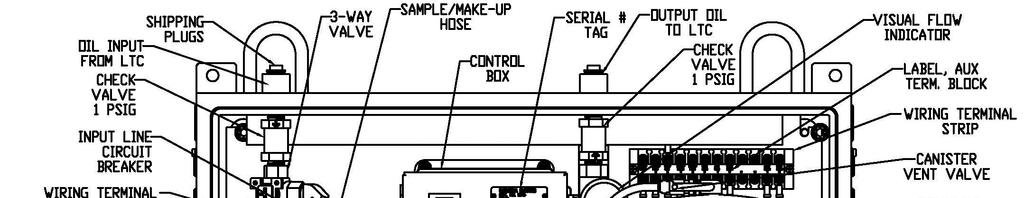
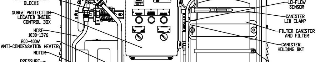
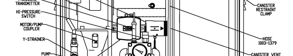
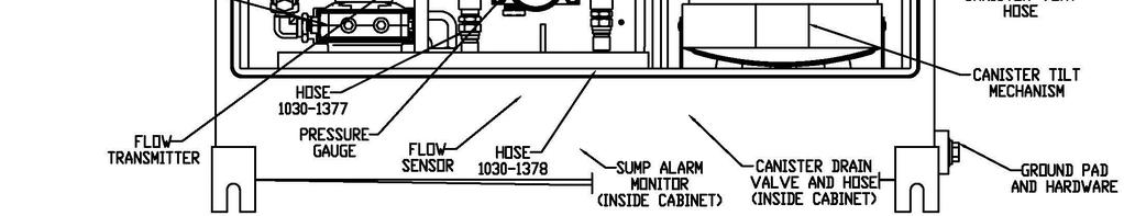
15 MAINTENANCE NOTE: Some optional equipment is shown. Figure 5 Component Identification 14
16 MAINTENANCE (continued) The compact LTC oil filtration system requires minimal maintenance; the unit has been designed to shut down if problems occur. To reset the alarm lights and place the filter system back in service, turn the power switch to OFF/RESET, then back ON. ANNUAL INSPECTION 1) Annually (or if the system has shut down due to LOW Flow), CLEAN out the Y Strainer before any other action. 2) Check system for leaks. 3) Check LTC oil level. 4) Check operation by turning to OFF/RESET and back ON. This will initiate a pump cycle. 5) Check the pressure on the gauge when the pump is running. If the pressure is above 60 PSI under normal temperature conditions, change the filter. 6) Check the service date of the filter cartridge. If it is beyond the manufacturer s recommended life cycle date, change the filter cartridge. SYSTEM FILTER REPLACEMENT 1) Turn the power switch to the OFF/RESET position. 2) Let the system set for a few minutes to allow system pressure to equalize. 3) Turn the 3-way valve to the right/horizontal position to isolate the LTC (see Figure 4 on page 11). Any remaining system pressure will be released through the make-up hose. 4) Loosen the left canister bracket wing nut (see Figure 4 on page 11). The right canister bracket bolt is fixed. 5) Support the canister while swinging the loose canister bracket to the right, out of the way. 6) Gently allow the canister to swing forward until the canister restraint cable stops its movement. 7) Place the canister vent hose in a suitable oil catch container. 8) Slowly open the canister vent valve to release any pressure that may still exist in the canister. 9) Place the canister DRAIN hose, located at the bottom of the canister, into a suitable oil catch container. Open the drain valve to drain oil from the canister. Close the drain valve once the canister is emptied. NOTE: This step is optional but reduces the chance of an oil spill during the filter change process. 10) Loosen and remove the canister lid clamp using the T handle. 11) Remove the canister lid and canister lid clamp; place aside in a clean area 15
17 MAINTENANCE: SYSTEM FILTER REPLACEMENT (continued) 12) Loosen and remove the hand tightened filter retaining nut located at the top of the exposed filter on the center post. Place aside in a clean area. If pleated filter option is used, remove the top filter adapter. 13) Lift out the filter element and place in a suitable container for later disposal. 14) Insert a fresh filter element, ensuring it seats properly on the bottom seal. If pleated filter option is used, replace the top filter adapter. 15) Replace and securely hand tighten the filter retaining nut on the center post. 16) Carefully inspect the filter lid seal ring for any signs of damage or wear and replace, if necessary. Then replace the canister lid, seating it properly. Install the lid clamp and T handle. Position the T handle so it will be parallel to the back of the cabinet. Use the T handle to tighten the lid clamp securely. 17) Gently swing the canister back to the vertical position and swing the canister bracket back into position. Replace the canister bracket washer and wing nut and securely hand tighten. 18) Check that the canister vent hose is in a suitable oil catch container and that the canister drain valve is CLOSED. 19) Turn the 3-way valve to the DOWN/vertical position. 20) Turn the pump motor control ON and monitor the canister vent hose for oil flow. NOTE: The pump may shut off due to a low flow alarm after 15 seconds. Return the power switch to the OFF/RESET position to reset the alarm and then back to the ON position to continue the filter canister filling operation. You may have to repeat this reset procedure several times before the filter canister is completely fully and de-aired. 21) Continue monitoring the canister vent hose until it is running solid with oil without any bubbles. 22) Turn the pump control to OFF and close the canister vent valve. 23) Turn the pump control to the ON position. 24) With the pump running, check for leaks and ensure that the visual paddlewheel flow indicator is spinning. 25) Check the LTC oil level and add any make-up oil following the Make-up Oil Procedure on page 17 of this manual. 26) System is now ready for normal operation. CAUTION: For low oil volume LTCs, up to 5 gal of make-up oil may need to be added to avoid tripping the LTC low oil level alarm after a filter cartridge change. 16
18 MAINTENANCE (continued) MAKE-UP OIL ADDITION PROCEDURE 1) Turn the pump control to the OFF/RESET position. 2) Place prime/make-up hose in a supply of clean transformer oil, strongly recommended to be placed above the height of the sample/prime valve. 3) Turn the 3-way valve to the RIGHT/horizontal position. 4) Turn the pump ON. Ensure the oil from the priming oil supply is flowing into the system. 5) After the desired quantity of oil has been introduced into the system, turn the pump control to the OFF/RESET position. 6) Turn the 3-way valve to the DOWN/vertical position. 7) Unit is now ready for normal operation. 8) With the system running, check for leaks. STRAINER CLEANING PROCEDURE 1) Turn the pump control to the OFF/RESET position. 2) Place a suitable oil catch tray under the strainer position. 3) Wait several minutes to allow the system pressure to dissipate. 4) Turn the 3-way valve to the RIGHT/horizontal position (any residual system pressure will vent through the prime/make-up hose). 5) Observe the pressure gauge, which should be at zero. If not at zero, after placing the canister vent hose in a suitable container, slowly open the canister vent valve to vent the pressure. 6) Slowly loosen and remove the strainer hex nut/seal that is holding the strainer screen. 7) Remove the strainer screen and clean out any debris. 8) Replace the strainer screen and the retainer hex nut/seal; tighten the hex nut. 9) Turn the 3-way valve to the DOWN/vertical position. 10) Turn the pump control from OFF/RESET to the ON position. 11) Monitor the canister vent hose for air that might have been trapped in the system. Close the canister vent valve when all air has been purged. 12) The system is now ready for normal operation. 13) With the system running, check for leaks. 17
19 TROUBLESHOOTING 1. Motor will not operate. a. Check for 115 VAC control power at terminals 2 and 7. b. Check for voltage at the motor. 2. Low Pressure and/or Low Flow a. Check motor power supply at terminals 2 and 7. b. Check operation of pump. c. Check that the LTC input valve is completely open. d. Check that the LTC oil level is above the anti-siphon hole level. e. Check the visual flow indicator for indications of the system s operation. 3. High Pressure and/or Low Flow a. Check to confirm the filter does not need to be changed. b. Check for other blockages in the system. c. Check the visual flow indicator for explanations of the system s operation. 4. General Oil Leaks a. Check connections for tightness b. Check tubing for cracks and replace, if necessary. REPLACEMENT PARTS AND SERVICE Please contact us at for replacement parts and/or service. Or visit us online at 18
20 APPENDIX A: General Dimensions Figure 6 Compact Oil Filtration System with Rear Mounting Dimensions 19
21 APPENDIX B: General Piping Diagrams NOTE: See written instructions and additional diagrams on Pages 9, 20 and 21. Figure 7 Installation Using Flexible Hose Kit (OPTIONAL) 20
 Place socket in vice and screw in hose counter-clockwise until the hose bottoms out (approx. 1.0 ). Back hose out 1/2 turn. Mark hose with grease pencil or equivalent.")
22 APPENDIX B (continued) FLEXIBLE HOSE KIT ASSEMBLY NOTES 1) Mark and cut hose to desired length using a fine tooth hacksaw or cutoff machine. 2) Remove nipple from socket and place nipple aside. 3) Place socket in vice and screw in hose counter-clockwise until the hose bottoms out (approx. 1.0 ). Back hose out 1/2 turn. Mark hose with grease pencil or equivalent. 4) Oil inside of hose and nipple threads liberally with transformer oil. Do not oil hose cover. 5) Screw the nipple assembly into the socket using a wrench on the nipple hex until the nipple hex shoulders against the socket. 6) Ensure the grease mark has not separated during the tightening of the assembly. Figure 8 Instructions for Installation of Flexible Hose Kit (Optional) 21
23 APPENDIX B (continued) Figure 9 Instructions for Anti-Siphon Hole on Suction Tube of Entrance Kit 22

24 APPENDIX C: Ladder/Point Wiring Diagrams Figure 10 23
25 APPENDIX C (continued) Figure 11 Standard Control/Alarm Circuit 24

26 APPENDIX D: Optional Flow & Pressure Transducers Typical Transducer Monitoring Loops See Standard Alarm Wiring on Page 8. Pre-Wired System Connections This Side Figure 12 Customer Alarm Relay Connections NOTE: All connections are located on the Aux Terminal strip located in the upper right hand corner of the main enclosure, behind the filter canister. For the Flow Transducer, connect the current loop to the terminal positions #1 (minus) and #2 (plus) on the Aux Terminal Strip. Shielded cable is recommended with the cable shield connected to terminal #3. For the Pressure Transducer, connect the current loop to the terminal positions #4 (minus) and #5 (plus) on the Aux Terminal Strip. Shielded cable is recommended with the cable shield connected to the terminal #3. 25
27 APPENDIX D (continued) Figure 13 Flow Transducer Configuration Panel 1. Setting the Flow Transducer LOW (4 ma) Endpoint a. With the system ON but the pump not running, locate the flow transducer and the flow transducer configuration panel (see Figure 4 on page 11). b. While watching the flow transducer INDICATOR LIGHT, press and hold both the SET and 4 buttons. c. Release them both when the INDICATOR LIGHT blinks. 2. Setting the Flow Transducer High (20 ma) Endpoint a. With the system ON and the pump running, locate the flow transducer and the flow transducer configuration panel (see Figure 4 on page 11). b. Allow the flow to stabilize for a minimum of 5 minutes. c. While watching the flow transducer INDICATOR LIGHT, press and hold both the SET and 20 buttons. d. Release them both when the INDICATOR LIGHT blinks. 3. The Pressure Transducer is factory calibrated for 4 0 PSIG and PSIG. NOTE: During the high and low flow transducer set point procedure, if the new settings are very different from the previous settings, it is possible to reverse the 4 ma and 20 ma set points so that the 4mA frequency is higher than the 20 ma frequency. The situation corrects itself after you complete both set points. If the new settings are close to the previous settings, you may safely set the low and high settings independently. 26
28 APPENDIX E: Optional Auto Run Cold System Optional Auto Run Cold System will automatically start the filtration system if the outside temperature falls below 20 F, even if no scheduled run period is programmed. This feature ensures the filtration system continues to provide clean mineral oil to the tank, protecting it during cold weather events and avoids the problem of cold weather starts which can produce high system pressure shut-downs. When the outside ambient temperature rises to above 30 F, the system reverts to the normal programmed run pattern. 27
29 APPENDIX F: Oil PCB-Free Statement SPX Transformer Solutions, Inc. certifies that the OF2 Oil Filtration System and any oil residue from factory testing prior to shipment will be free of PCB (Polychlorinated Biphenyl) contamination. REPLACEMENT PARTS AND SERVICE Please contact us at for replacement parts and/or service. Or visit us online at 28
Installation Manual FTI-10A & FTI-20A SINGLE TANK. Automated Fuel Maintenance System FUEL TECHNOLOGIES INTERNATIONAL
 Installation Manual Automated Fuel Maintenance System FTI-10A & FTI-20A SINGLE TANK FUEL TECHNOLOGIES INTERNATIONAL 05/01/2016 Rev A Fuel Technologies FTI-10A & FTI-20A Single Tank Installation Manual
# and # FAST Fuel System Kits
 1 INSTRUCTIONS #307500 and #307501 Fuel System Kits Thank you for choosing products; we are proud to be your manufacturer of choice. Please read this instruction sheet carefully before beginning the installation.
WARCO CHEMAG SERIES GH FILTERS
 WARCO CHEMAG SERIES GH FILTERS High Performance Pleated & Bag Type Filtration Systems INSTALLATION, OPERATION, AND MAINTENANCE INSTRUCTIONS Thank you for your purchase of a WARCO Series GH Filtration System.
Installation Manual. Automated Fuel. Maintenance. System FUEL TECHNOLOGIES INTERNATIONAL LLC
 Installation Manual Automated Fuel Maintenance System FTI-10A & FTI-20A FUEL TECHNOLOGIES INTERNATIONAL LLC Replacement Manuals Available on Website: www.fueltechnologiesinternational.com 03/01/2011 -
Maintenance Manual. Automated Fuel Maintenance System FTI-5A SINGLE TANK FUEL TECHNOLOGIES INTERNATIONAL
 Maintenance Manual Automated Fuel Maintenance System FTI-5A SINGLE TANK FUEL TECHNOLOGIES INTERNATIONAL 05/01/2016 Rev A Fuel Technologies FTI-5A Single Tank Maintenance Section FTI - Fuel Maintenance
Installation Manual. Automated Fuel Maintenance System FTI-5A FUEL TECHNOLOGIES INTERNATIONAL
 Installation Manual Automated Fuel Maintenance System FTI-5A FUEL TECHNOLOGIES INTERNATIONAL Replacement Manuals Available on Website: www.fueltechnologiesinternational.com 07/15/2015 Rev E Fuel Technologies
Low Profile J Series Power Unit with Vane Pump
 Low Profile J Series Power Unit with Vane Pump READ ALL INSTRUCTIONS CAREFULLY BEFORE ATTEMPTING TO ASSEMBLE, INSTALL, OPERATE OR MAINTAIN THE PRODUCT DESCRIBED. PROTECT YOURSELF AND OTHERS BY OBSERVING
To ensure proper installation, digital pictures with contact information to before startup.
 Check List for Optimal Filter Performance? There should be no back-pressure on the flush line. A 1 valve should have a 2 waste line, and 2 valve should have a 3 waste line. Do not use rubber hosing or
Operations Manual. Automated Fuel Maintenance System FUEL TECHNOLOGIES INTERNATIONAL
 Operations Manual Automated Fuel Maintenance System FTI-10A & 20A FUEL TECHNOLOGIES INTERNATIONAL Replacement Manuals Available on Website: www.fueltechnologiesinternational.com 07/15/2015 Rev E Fuel Technologies
DP5 Pump. 5:1, Air-operated, Heavy Duty, Oil. General. Operation. Technical Data. Installation R1 09/10
 DP5 Pump 5:1, Air-operated, Heavy Duty, Oil General The DP5 Pump is a compressed air-operated reciprocating piston medium pressure pump. These pumps are suitable for distribution of all types of light
AIR CLEANERS Model MC 3000 OWNER S MANUAL CAUTION Read complete instructions before operating. Please file for future reference.
 AIR CLEANERS Model MC 3000 OWNER S MANUAL CAUTION Read complete instructions before operating. Please file for future reference. MODEL MC 3000 SPECIFICATION Input Volts: 208-230/430 VAC, 60Hz, 3 Phase
DP3 Pump. 3:1, Air-operated, Oil. General. Operation. Technical Data. Installation R0 10/09. 35a 35b 35c
 DP3 Pump 3:1, Air-operated, Oil General The DP3 Pump is a compressed air-operated piston reciprocating medium pressure pump. Suitable for medium flow transfer of high viscosity lubricants and for oil delivery
Maintenance Manual. Automated. Fuel Maintenance System FTI-5A. FUEL TECHNOLOGIES INTERNATIONAL LLC
 Maintenance Manual Automated Fuel Maintenance System FTI-5A FUEL TECHNOLOGIES INTERNATIONAL LLC www.fueltechnologiesinternational.com 03/01/2011 - Fuel Technologies FTI-5A Maintenance Section FTI - Fuel
Exercise 3-1. Basic Hydraulic Circuit EXERCISE OBJECTIVE DISCUSSION OUTLINE DISCUSSION. Complete hydraulic circuit
 Exercise 3-1 Basic Hydraulic Circuit EXERCISE OBJECTIVE When you have completed this exercise, you will be familiar with the hydraulic schematic and components of the nacelle trainer. You will identify
Purging Air From Divider Block Lubrication Systems
 FROST ENGINEERING SERVICE Purging Air From Lubrication Systems A D I V I S I O N O F G E C S E Y S A L E S & S E R V I C E DESCRIPTION Divider block lubrication systems operate correctly only when all
Maintenance Manual WITH ONE SUBMERSIBLE PUMP. Automated Fuel Maintenance System FTI-5A FUEL TECHNOLOGIES INTERNATIONAL LLC
 Maintenance Manual WITH ONE SUBMERSIBLE PUMP Automated Fuel Maintenance System FTI-5A FUEL TECHNOLOGIES INTERNATIONAL LLC Replacement Manuals Available on Website: www.fueltechnologiesinternational.com
TECHNICAL DATA. Table 1: Model F1 Dry Valve Part Numbers and Specifications
 Page 1 of 11 1. DESCRIPTION The Viking Model F-2 Dry Pipe Valve is a latching differential valve used to separate the water supply from the dry pipe sprinkler system. The valve combines a positive latching
MINI MANIA REMOTE OIL COOLER INSTALLATION INSTRUCTIONS P/N NME1055
 MINI MANIA REMOTE OIL COOLER INSTALLATION INSTRUCTIONS P/N NME1055 Mini Mania s Cooper S Remote Oil Cooler Kit is designed to reduce operating temperatures by cooling the motor oil using an external radiator.
MODEL MC1500 Installation and Operation Manual Important:
 MODEL MC1500 Installation and Operation Manual Important: This manual contains specific cautionary statements relative to worker safety. Read this manual thoroughly and follow as directed. It is impossible
Model AM2 M40 Panel Installation, Operation, and Maintenance Manual
 Model AM2 M40 Panel Installation, Operation, and Maintenance Manual RECEIVING AND INSPECTION Upon receiving unit, check for any interior and exterior damage, and if found, report it immediately to the
LABORATORY ZERO AIR GENERATOR MODEL N-GC1500 USER S MANUAL
 LABORATORY ZERO AIR GENERATOR MODEL N-GC1500 USER S MANUAL Content 1. Introduction...2 2. Important safety instruction...3 3. System component...4 4. Engineering design overview...5 5. Installation...6
BOSS 107 SEPARATOR SYSTEM INSTALLATION & APPLICATION MANUAL
 Website: www.recoveredenergy.com Email: oilwatersales@recoveredenergy.com BOSS 107 SEPARATOR SYSTEM INSTALLATION & APPLICATION MANUAL BOSS 2.2T/107 BOSS 5T/107 BOSS 11T/107 BOSS 25T/107 BOSS 45T/107 Installation
SIGNETMARINE. Livewell Bait Pump Alarm. No Dead Bait.
 B A I T WAT C H SIGNETMARINE Livewell Bait Pump Alarm No Dead Bait. The SIGNETMARINE BaitWatch System alerts you to a livewell pump problem before your fishing trip turns into one. The loud alarm and dual-color
INOVA HIGHTECH Ltd. MEP 002/003 Auto Starter Manual
 INOVA HIGHTECH Ltd. MEP 002/003 Auto Starter Manual Complete Installation and Operating Manual for the MEP 002/003 Auto / Remote Starter for the following MEP Power Generators: MEP 002A/003A/011A/802A/803A/811A
Val-Matic Air / Oil Hydraulic Panel Pump Control System. Operation, Maintenance and Installation Manual
 Manual No. 5AOP-OM1-2 Val-Matic Air / Oil Hydraulic Panel Pump Control System Operation, Maintenance and Installation Manual INTRODUCTION... 1 RECEIVING AND STORAGE... 1 DESCRIPTION OF OPERATION... 1 INSTALLATION...
XCITE Owner s Manual. Reso-not TM Damping System XCITE 1502C HYDRAULIC POWER SUPPLY
 Reso-not TM Damping System XCITE Owner s Manual 1502C HYDRAULIC POWER SUPPLY Xcite Systems Corporation 675 Cincinnati RDS Batavia - 1 Pike Cincinnati, Ohio 45245 Tel: (239) 980-9093 Fax: (239) 985-0074
Power Train. Chapter 5
 Chapter Power Train Spefications................................................................. -3 Test Spefications........................................................ -3 Repair Spefications.......................................................
INSTALLATION INSTRUCTIONS FOR THE TRUCK MOUNTED VIPER ADDITIVE INJECTION SYSTEM GTP-8776C
 INSTALLATION INSTRUCTIONS FOR THE TRUCK MOUNTED VIPER ADDITIVE INJECTION SYSTEM GTP-8776C This additive injection system was designed to be used with five gallon jug of additive. The system is supplied
IMI vibration switch USER MANUAL INSTALLATION - OPERATION - MAINTENANCE
 USER MANUAL IMI vibration switch INSTALLATION - OPERATION - MAINTENANCE Z0929039_A ISSUED 03/2017 READ AND UNDERSTAND THIS MANUAL PRIOR TO OPERATING OR SERVICING THIS PRODUCT. contents Overview General
HARMSCO Hurricane Swing Bolt Water Filters Models: HUR 1X170FL, HUR 3X170FL HUR 5X170FL, & HUR 8X170FL
 Models: HUR 1X170FL, HUR 3X170FL HUR 5X170FL, & HUR 8X170FL INSTALLATION AND OPERATION MANUAL HUR 8X170FL HUR 5X170FL HUR 3X170FL HUR 1X170FL Harmsco Filtration Products With Patented Up-Flow and Tangential/Rotational
Industrial Pro FH239 Series Filter/Separator/Warmer Installation Instructions
 Industrial Pro FH239 Series Filter/Separator/Warmer Installation Instructions K L Cover Industrial Pro Single Short H I W A B D F P C E J Bottom Bowl G Vent Cap Filter Element (includes part C) I R S T
FA-ST Filtration Analysis Services Technology Ltd
 Engine Bypass Oil Filter System FA-ST Ltd Unit 4 Foxwood Road Dunston Trading Estate Chesterfield S41 9RF T: +44(0) 1246 268900 Fax +44(0) 1246 268904 www.fa-st.co.uk The by pass filter system passes only
MASTER COALESCER JR & PORTABLE MASTER COALESCER JR AIR PUMP MODEL INSTALLATION MANUAL
 MASTER COALESCER JR & PORTABLE MASTER COALESCER JR AIR PUMP MODEL INSTALLATION MANUAL INSTALLATION: CHOOSING THE LOCATION: Locate the coalescer as near to the intended point of use as possible. Avoid high
TBI /2012 TRAUMATIC BRAIN INJURY DEVICE
 USER MANUAL TBI 0310 6/2012 TRAUMATIC BRAIN INJURY DEVICE Page 1 of 26 Setting up the TBI 0310 Head Impactor The TBI 0310 Head Impactor when fully assembled has the following components: 1. Control box
STS SERIES. Enclosed Automated Fuel Maintenance Systems (STS)
") STS SERIES Enclosed Automated Fuel Maintenance Systems (STS) AXI s Enclosed Automated Fuel Maintenance Systems are programmable and automated self-contained, stand-alone fuel filtration, separation, and
STS SERIES Enclosed Automated Fuel Maintenance Systems (STS) AXI s Enclosed Automated Fuel Maintenance Systems are programmable and automated self-contained, stand-alone fuel filtration, separation, and
As diesel fuel ages it degrades in 2 ways: particulate formation, and biological growth.
 ESS.WP.534.YQA Fuel Quality and Polishing Your Questions Answered (20) Fuel Quality and Polishing earth safe Fuel Systems for Critical Power 18.1 Why is filtration / polishing needed? Filtration / Polishing
DP556 Pump. 55:1, Air-operated, Grease. General. Operation. Technical Data. Installation. Mounting with Reinforced Cover (Recommended)
") DP556 Pump 55:1, Air-operated, Grease General The DP556 Pump is a compressed air-operated reciprocating piston pump. This high capacity demand pump is compatible with mineral and synthetic grease and suitable
DP556 Pump 55:1, Air-operated, Grease General The DP556 Pump is a compressed air-operated reciprocating piston pump. This high capacity demand pump is compatible with mineral and synthetic grease and suitable
KJ4000LW Operating Instructions & Parts Manual NSN
 KJ4000LW Operating Instructions & Parts Manual NSN Mandus Group Ltd. KJ4000LW Operators Manual Date: 1 Oct. 2004 TABLE OF CONTENTS General Safety Instructions...Page 1 Operator Instructions...Page 2 KJ4000LW
Duramax Lift Pump Kit 9-11 PSI Installation Instructions P/N# D
 2001-10 Duramax Lift Pump Kit 9-11 PSI Installation Instructions P/N# 1050320D PLEASE READ ALL INSTRUCTIONS CAREULLY BEORE INSTALLATION Kit Contents 1500365-P2 1500330-D lowmax Lift Pump V3 lowmax Wiring
Operating Manual. High Performance Vacuum Pump Models and 15600
 Operating Manual High Performance Vacuum Pump Models 15400 and 15600 CoolTech High Performance Vacuum Pumps Congratulations on purchasing one of Robinair s top quality CoolTech vacuum pumps. Your pump
The Better Dispensers by Bergquist
 The Better Dispensers by Bergquist Ball valve shut-off downstream of pump Adapter shelf Fairbanks scale included with most models Wall mounted switch 1" Neptune meter and register Break-away w/bleeder
Application Engineering
 Application Engineering February, 2009 Copeland Digital Compressor Controller Introduction The Digital Compressor Controller is the electronics interface between the Copeland Scroll Digital Compressor
Auxiliary Equipment. Table of Contents. Auxiliary Equipment H-1. Product Product Code Technical Instructions Page #
 Table of Contents Product Product Code Technical Instructions Page # Pneumatic Air Station Equipment 201/656/908 155-005/049/086/137P25 H-3 Pressure Gauges GA142AP 155-025P25 H-7 External Restrictors 184
MC2500. Installation and Operation Manual
 MC2500 Installation and Operation Manual Important: This manual contains specific cautionary statements relative to worker safety. Read this manual thoroughly and follow as directed. It is impossible to
INSTALLATION, OPERATION AND MAINTENANCE MANUAL (IOM)
") INSTALLATION, OPERATION AND MAINTENANCE MANUAL (IOM) IOM-1088 03-16 Model 1088 Vacu-Gard Blanketing Valve ISO Registered Company SECTION I I. DESCRIPTION AND SCOPE The Model 1088 Vacu-Gard is a tank blanketing
INSTALLATION, OPERATION AND MAINTENANCE MANUAL (IOM) IOM-1088 03-16 Model 1088 Vacu-Gard Blanketing Valve ISO Registered Company SECTION I I. DESCRIPTION AND SCOPE The Model 1088 Vacu-Gard is a tank blanketing
NECO Pumping Systems
 INSTALLATION OPERATION & MAINTENANCE INSTRUCTIONS For Your NECO Pumping Systems PACKAGED CIRCULATING SYSTEM THIS COMPLETELY ASSEMBLED, TESTED, PACKAGED CIRCULATING SYSTEM IS OF THE HIGHEST QUALITY AND
INSTALL MANUAL. FOR ON LINE ORDERING- E Commerce Visit Our Website
 INSTALL MANUAL FOR ON LINE ORDERING- E Commerce Visit Our Website WWW.PRESSUREGUARD.COM Contact Information Technical Support: Chris@pressureguard.com Sales Support: Sales@pressureguard.com By Phone: 615-227-6024
MICRO-AIR DUST COLLECTOR Installation and Operation Manual MODEL RP6-2, RP-3, RP8-2 & RP-3
 MICRO-AIR DUST COLLECTOR Installation and Operation Manual MODEL RP6-2, RP-3, RP8-2 & RP-3 Important: This manual contains specific cautionary statements relative to worker safety. Read this manual thoroughly
Exercise 3-1. Basic Hydraulic Circuit EXERCISE OBJECTIVE DISCUSSION OUTLINE DISCUSSION. Complete hydraulic circuit
 Exercise 3-1 Basic Hydraulic Circuit EXERCISE OBJECTIVE When you have completed this exercise, you will be familiar with the hydraulic schematic and components of the nacelle trainer. You will identify
A Filtration Primer. Filter Elements. High Pressure Filters. Tank-Mounted, Return Line and Medium Pressure Filters. Water Service Filters
 A Filtration Primer Filter Elements High Pressure Filters Tank-Mounted, Return Line and Medium Pressure Filters Water Service Filters Section 6 Reservoir Accessories SCHROEDER INDUSTRIES 259 Principles
This catalog contains the following geothermal accessory products and specification guides:
 f o r r e s i d e n t i a l s y s t e m s Geothermal systems offer an effective way to cut utility costs while ensuring comfort. Heat Controller s line includes two stage and single stage geothermal heat
OWNER S MANUAL D.E. CARTRIDGE. Installation Operation Parts. Models PCDE-30 PCDE-40
 D.E. CARTRIDGE OWNER S MANUAL Installation Operation Parts Models PCDE-30 PCDE-40 2200 East Sturgis Road, Oxnard, CA 93030 Ph. (805) 981-0262 Fax (805) 981-9403 www.waterwayplastics.com waterway@waterwayplastics.com
8000 Series Liquid Flow Meters
 PRODUCT DATA SHEET 8000 Series Liquid Flow Meters Advanced microprocessorbased flow measurement technology in a compact, leak-tight package Flow ranges from 0.2 to 227 LPM / 0.05 to 60 GPM Accuracy of
VARNA Products 15 GPM (57 LPM) Prelube Kit for MTU 4000 Series Marine Engines
 Prelube Kit for MTU 4000 Series Marine Engines") VARNA Products 15 GPM (57 LPM) Prelube Kit for MTU 4000 Series Marine Engines Installation and Users Manual For the following Prelube Kits: VARNA Products P/N 6423 Kit for 208 VAC 3 Phase VARNA Products
VARNA Products 15 GPM (57 LPM) Prelube Kit for MTU 4000 Series Marine Engines Installation and Users Manual For the following Prelube Kits: VARNA Products P/N 6423 Kit for 208 VAC 3 Phase VARNA Products
DuraMAC LIGHT COMMERCIAL & IRRIGATION WATER PRESSURE BOOSTER SYSTEM INSTALLATION INSTRUCTIONS
 DuraMAC LIGHT COMMERCIAL & IRRIGATION WATER PRESSURE BOOSTER SYSTEM INSTALLATION INSTRUCTIONS The DuraMAC TM Water Pressure Booster System is the first booster pump of its kind to be designed for virtually
TECHNICAL DATA. model f-1 2. LISTINGS AND APPROVALS 3. TECHNICAL DATA. Page 1 of 11
 Page 1 of 11 1. DESCRIPTION The Viking Model F-1 Dry Pipe Valve is a latching differential valve used to separate the water supply from the dry pipe sprinkler system. The valve combines a positive latching
Fuel Pro Series Filter/Separator/Warmer Installation Instructions
 Fuel Pro Series Filter/Separator/Warmer Installation Instructions Standard and Plus Series A B C D Vent Cap and Assembly (part no SP1053) Includes Vent Cap and Vent Cap Seal Part Description Part Number
TECHNICAL DATA CAUTION
 Page 1 of 6 1. DESCRIPTION The Viking Model D-2 Accelerator is a quick-opening device, with an integral anti-flood assembly, used to increase the operating speed of a differential type dry pipe valve.
PowerLevel s e r i e s
 Owner s Manual Hydraulic Leveling CONTENTS Introduction Operation Control Panel Automatic Leveling Manual Leveling Retracting Jacks Remote Operation Care & Maintenance Troubleshooting Error Codes 1 2 2
Advantage-D. Operating Instructions and Maintenance Manual. Central Vacuum Systems (Expandable/Modular Models) (Ver.
 (Ver.") Advantage-D Series 3 Central Vacuum Systems (Expandable/Modular Models) (Ver. 8/05) Operating Instructions and Maintenance Manual DESCRIPTION The Becker Advantage-D and Advantage-L central vacuum systems
Advantage-D Series 3 Central Vacuum Systems (Expandable/Modular Models) (Ver. 8/05) Operating Instructions and Maintenance Manual DESCRIPTION The Becker Advantage-D and Advantage-L central vacuum systems
Heating and Gas Installations - December 2014
 This is an example of good practice maintenance specifications. It is not exhaustive and should only be used to assist with facilities management or specification of a maintenance contract. Emergency Gas
Tests & Adjustments - General Machine. General Safety Hydraulic Tank Turbo Boost Regulator
 Section 8.1 Tests & Adjustments - General Machine General Safety......................................... 8.1.2 Hydraulic Tank Turbo Boost Regulator........................ 8.1.2 Hydraulic Tank Safety
Rev: Flow Max 115V AC Fluid Pump
 Flow Max 115V AC Fluid Pump by Duraself Installation and Owner s Manual (For Aftermarket Applications) Table of Contents Introduction... 2 Parts List... 2 Resources Required... 3 Installation... 3 General
Operation and Maintenance Manual
 BM / BMA Hydrometers ½ Operation and Maintenance Manual i This manual is intended for use by the users of this equipment. The information contained herein is the property of the Arad Ltd. Dalia and may
BMK-30. Heavy-Duty By-Pass Filtration System Installation and Servicing Instructions
 BMK-30 Heavy-Duty By-Pass Filtration System Installation and Servicing Instructions IMPORTANT NOTICE Read all instructions completely before attempting to install this unit. Improper installation could
TECHNICAL DATA. Q= C v P Cv = Flow Factor (GPM/1 PSI P)
") 1 of 9 1. DESCRIPTION The Viking 2 (DN50) is a quick-opening, differential diaphragm, flood valve with one moving part. The deluge valve is used to control water flow in deluge and preaction sprinkler
1 of 9 1. DESCRIPTION The Viking 2 (DN50) is a quick-opening, differential diaphragm, flood valve with one moving part. The deluge valve is used to control water flow in deluge and preaction sprinkler
Installation Instructions for Bike Fixtation. Bottle Fill and Bike Wash Stations Manual Rev. B
 15540 Woodinville Redmond Rd NE, Suite A-200, 2647 37th Woodinville, Ave. S Unit WA 1, Minneapolis 98072 MN 55406 Phone: 425.483.7000 Phone: 612-568-3498 Email: salesandsupport@sportworks.com E-mail: info@bikefixtation.com
SPECIAL REVERSE HORIZONTAL FLOW ENCLOSURE OPERATING AND MAINTENANCE MANUAL. Issue No: 1
 SPECIAL REVERSE HORIZONTAL FLOW ENCLOSURE OPERATING AND MAINTENANCE MANUAL Issue No: 1 Certificate No: 0954499 CE Marking certifies that this equipment conforms to the following EEC directives: - Low Voltage
Farval. Dualine Installation System Start-Up. Bulletin DL300 BIJUR DELIMON INTERNATIONAL
 Farval Dualine Installation System Start-Up Bulletin DL300 BIJUR DELIMON INTERNATIONAL 2685 Airport Road Kinston, NC 28504 Tel. 800-227-1063 Fax: 252-527-9232 website: www.bijurdelimon.com DC1-1 SECTION
D-04/G-04 Maintenance
 D-04/G-04 Maintenance NOTE: The numbers in parentheses are the Ref. Nos. on the illustrations in the Parts Manual. Daily Check the oil level and the condition of the oil. The oil level should be 1/4 in.
AEROMOTIVE Part # Generic Fuel System Kit INSTALLATION INSTRUCTIONS
 AEROMOTIVE Part # 17242 Generic Fuel System Kit INSTALLATION INSTRUCTIONS CAUTION: Installation of this product requires detailed knowledge of automotive systems and repair procedures. We recommend that
Distributed By: M&M Control Service, Inc Product Product Code Technical Instructions Page #
 Table of Contents Product Product Code Technical Instructions Page # Pneumatic Air Station Equipment 201/656/908 155-005/049/086/137P25 H-3 Pressure Gauges GA142AP 155-025P25 H-7 External Restrictors 184
HYGRODYNAMICS DEW POINT MONITOR MODEL 8092P 8092P-230VAC TABLE OF CONTENTS DIAGRAMS
 HYGRODYNAMICS DEW POINT MONITOR MODEL 8092P 8092P-230VAC TABLE OF CONTENTS SPECIFICATIONS 1 PRINCIPLE OF OPERATION 1 INSTALLATION 2 Choosing a Sampling Location 2 Mounting the Enclosure 2 Remote Alarm
Self Cleaning Hood System Installation, Operation, and Maintenance Manual
 Self Cleaning Hood System Installation, Operation, and Maintenance Manual RECEIVING AND INSPECTION Upon receiving unit, check for any interior and exterior damage, and if found, report it immediately to
BEFORE BEGINNING INSTALLATION
 COMPLETE CHASSIS FUEL LINE KITS For 1996-2000 Honda Civic Equipped with B-Series Engine INSTALLATION INSTRUCTIONS PLEASE study these instructions carefully before beginning this installation. Most installations
FORD POWERSTROKE 6.0L DIESEL ENGINE
 #8 INSTALLATION MANUAL MODEL FP-100 & FP-150 With New Quick Connect Components! 2003-2007 FORD POWERSTROKE 6.0L DIESEL ENGINE Performance Fuel System Parts PLEASE READ THESE INSTRUCTIONS THOROUGHLY BEFORE
Operating and Installation Instructions
 Model Number 40401-c (-sp) Electronic Fuel Pump Operating and Installation Instructions This Product is Patent Pending. Application available upon request CAUTION! This product is to be installed only
ProFlo FatBoy
 The Standard For Professional Grade Diaphragm Pumps. ProFlo 3300 5500 FatBoy Operational and Installation Guidelines, Repair & Parts Contents 3300 5500 Fatboy Operational and Installation Guidelines...2
AEROMOTIVE Part # Generic Fuel System Kit INSTALLATION INSTRUCTIONS
 AEROMOTIVE Part # 17126 Generic Fuel System Kit INSTALLATION INSTRUCTIONS CAUTION: Installation of this product requires detailed knowledge of automotive systems and repair procedures. We recommend that
CARTRIDGE FILTER SYSTEMS OWNER S MANUAL
 CARTRIDGE FILTER SYSTEMS OWNER S MANUAL Installation Operation Parts Designed, Engineered & Manufactured in the USA. 2017 Waterway Plastics 2200 East Sturgis Road, Oxnard CA 93030 Phone 805.981.0262 Fax
Steam/Water Washdown Units Safety and Operation Installation and Maintenance Instructions
 INSTALLATION AND MAINTENANCE INSTRUCTIONS IM-8-002-US October 2016 Steam/Water Washdown Units Safety and Operation Installation and Maintenance Instructions These instructions should be read by the Company
AEROMOTIVE Part # Generic Fuel System Kit INSTALLATION INSTRUCTIONS
 AEROMOTIVE Part # 17125 Generic Fuel System Kit INSTALLATION INSTRUCTIONS CAUTION: Installation of this product requires detailed knowledge of automotive systems and repair procedures. We recommend that
INDUSTRIAL DIESEL TUNE SYSTEM
 INDUSTRIAL DIESEL TUNE SYSTEM OPERATORS MANUAL FOR SERIAL NUMBERS 110000 AND ON 00-841 REV. 1 DieselTune 4000 Operators Manual Table of Contents System Features and Functions... 3 System Features... 4
BMK-18 U.S. Patent #5,298,158
 BMK- U.S. Patent #5,29,5 Marine Dual Remote Filtration System Mounting Kit Installation and Servicing Instructions IMPORTANT NOTICE Read all instructions completely before attempting to install this unit.
EJECTORS GENERAL OPERATION & MAINTENANCE MANUAL
 EJECTORS GENERAL OPERATION & MAINTENANCE MANUAL The information contained in this manual was current at the time of printing. The most current versions of all Hydro Instruments manuals can be found on
Flow Max. by Duraself. Flow Max by Duraself. Fluid Pump. Installation and Owner s Manual (For Aftermarket Applications)
") Flow Max Installation and Owner s Manual (For Aftermarket Applications) Table of Contents Introduction... 2 Parts List... 2 Resources Required... 3 Installation... 3 General Installation Instructions...
Flow Max Installation and Owner s Manual (For Aftermarket Applications) Table of Contents Introduction... 2 Parts List... 2 Resources Required... 3 Installation... 3 General Installation Instructions...
P445 Series Electronic Lube Oil Control
 FANs 125, 121 s Section P Product/Technical Bulletin P445 Issue Date 0100 P445 Series Electronic Lube Oil The P445 Series Electronic Lube Oil is designed for use on refrigeration compressors equipped with
Technical Information
 Technical Information Installation, Operation, Installation, Operation and Maintenance and Maintenance Manual Manual Balston Series "SR" Steam Filters USFDA, USDA, and 3A Compliance Balston SR Steam Filters
A Complete Guide to Spiratec Rotor (CS41018/CS41011) & Remote Centrifuge Product Benefits & Installation Instructions
 & Remote Centrifuge Product Benefits & Installation Instructions") A Complete Guide to Spiratec Rotor (CS41018/CS41011) & Remote Centrifuge Product Benefits & Installation Instructions This d describes: Product benefits Remote centrifuge housing specifications How to
A Complete Guide to Spiratec Rotor (CS41018/CS41011) & Remote Centrifuge Product Benefits & Installation Instructions This d describes: Product benefits Remote centrifuge housing specifications How to
Product Features: Removes 99% of free water. Available with 2, 10, or 30 micron Aquabloc II media
 120A and 120B Series Fuel Filter/Water Separators Instruction Part Number 10219 Rev B Overview: 120A and 120B fuel filter/water separators are designed to be installed on the suction side of the fuel system
Application Engineering
 Application Engineering March 2011 Copeland Digital Compressor Controller Introduction The Digital Compressor Controller is the electronics interface between the Copeland Scroll Digital compressor or the
DODGE COOL LUBE 2 for Sleevoil Pillow Blocks Part Numbers , , ,
 DODGE COOL LUBE for Sleevoil Pillow Blocks Part s 063487, 063488, 07889, 07890 These instructions must be read thoroughly before installing or operating this product. WARNING: To ensure the drive is not
Thread Protector Cleaner (Large Capacity)
") Revision: 1 Thread Protector Cleaner (Large Capacity) Operation and Maintenance Manual Hub City Iron Works 700 E Texas Ave. Rayne, LA 70578 Phone: (337) 334-6969 Fax: (337) 365-6565 www.hubcityironworks.com
Revision: 1 Thread Protector Cleaner (Large Capacity) Operation and Maintenance Manual Hub City Iron Works 700 E Texas Ave. Rayne, LA 70578 Phone: (337) 334-6969 Fax: (337) 365-6565 www.hubcityironworks.com
All Racor filter materials and seals are compatible with ultra-low sulphur diesel (ULSD) fuel and B2 to B20 Biodiesel. See Racor bulletin 7679.
 fuel and B2 to B20 Biodiesel. See Racor bulletin 7679.") 000MA Water-in-fuel sensor and indicator. MA units have shielded see-thru bowls; MAM bowls are all-metal. UL-listed drain valve and water sensor probe options are available. Turbine Series Electric Primer
000MA Water-in-fuel sensor and indicator. MA units have shielded see-thru bowls; MAM bowls are all-metal. UL-listed drain valve and water sensor probe options are available. Turbine Series Electric Primer
Priming Systems Installation Instructions
 Priming Systems Installation Instructions System Components: Single Priming Pump: Single VAP Valve Systems: Control Panel Activated... 2 Auto Prime (Pressure Switch) Activated... 3 Multiple VAP Valve Systems...
DISCONTINUED. Installation. Aerada 900 Series Futura Faucet. With Accu-Zone (AZ) Infrared Control
 Infrared Control") Aerada 900 Series Futura Faucet With Accu-Zone (AZ) Infrared Control BRADLEY SC A S53-141 4" Centerset S53-148 4" Centerset, no Solenoid Valve S53-186 4" Centerset with 8" Trim Plate S53-285 Centershank
Aerada 900 Series Futura Faucet With Accu-Zone (AZ) Infrared Control BRADLEY SC A S53-141 4" Centerset S53-148 4" Centerset, no Solenoid Valve S53-186 4" Centerset with 8" Trim Plate S53-285 Centershank
Eclipse GEN 2.0 CAFSystem, Model 150-ESECL as used with TC20 Series PTO Installation Instructions
 Eclipse GEN 2.0 CAFSystem, Model 150-ESECL as used with TC20 Series PTO Installation Instructions Read Read through the the safety installation information instructions overhaul carefully instructions
AEROMOTIVE Part # & Generic Fuel System Kit INSTALLATION INSTRUCTIONS
 AEROMOTIVE Part # 17135 & 17136 Generic Fuel System Kit INSTALLATION INSTRUCTIONS CAUTION: Installation of this product requires detailed knowledge of automotive systems and repair procedures. We recommend
TECHNICAL DATA. Q= C v P S
 1 of 9 1. DESCRIPTION The Viking Model E-1 Deluge Valve is a quick-opening, differential diaphragm, flood valve with one moving part. The deluge valve is used to control water flow in deluge and preaction
Water Valve Shutoff. WVS Water Valve Shutoff
 Water Valve Shutoff Monitors flooding from leaking or broken water line Automatic control of main water supply line Form C Relay output for external monitoring devices Visual and audible status indicators