An engineering & product selection guide for turntable bearings
|
|
|
- Shana Jackson
- 6 years ago
- Views:
Transcription


1 Catalog 390 slewing RING Turntable Bearings Turning Ideas into Engineered Solutions An engineering & product selection guide for turntable bearings
2
3 Slewing Ring / Turntable Bearing Reference Guide Divisional Office 2860 McCracken Street Muskegon, MI Tel: +1 (231) Fax: +1 (231) Customer Service Toll Free
4 Section 1 Introduction Slewing Ring / Turntable Bearings Catalog 390 KAYDON Corporation 2008 Table of Contents Page number Section 1 Introduction & Overview... 3 Introduction Product Overview/Selection Guide Application Images Section 2 Technical Information & Guide Application & Load Analysis Bearing Features Section 3 Installation & Maintenance Design Considerations (for the equipment designer) Installation Instructions (for the equipment builder) Maintenance Instructions (for the equipment user) Appropriate Grease Lubricants Section 4 Bearings Tables & Ratings Glossary RK Series Four-Point Contact HS Series Four-Point Contact HT Series Four-Point Contact MT Series Four-Point Contact Pinions for RK, HS & MT Series KH Series Four-Point Contact XT Series Four-Point Contact DT Series Eight-Point Contact XR Series Cross Roller TR Series Three-Row Roller Section 5 Specialty Products & Services WireX Wire Race Bearings Custom Bearings Remanufacturing Program Endurakote Plating Section 6 Appendix & Sales Information Specification Data Sheets Kaydon Website Kaydon Literature Warranty & Legal Information The design and application information contained in this catalog is for illustration only. Responsibility for the application of the products contained in this catalog rests solely with the equipment designer or user. In spite of our best efforts, the material contained in this catalog may contain inaccuracies and typographical errors
5 Introduction Nobody makes more advanced custom bearings than KAYDON. Kaydon has been one of North America s leading producers of large diameter ball and roller bearings since it was established in 1941, and is considered one of the pioneers of large bearing technology. Engineering Capability In addition to a range of catalog turntable bearings, Kaydon can provide a wide range of custom manufactured bearings to meet your specifications. Upon request, Kaydon s experienced and knowledgeable professionals can provide engineering expertise and analysis in a wide variety of areas. Our engineering team uses current computer technology supported by advanced resources to analyze the most challenging specifications. With these resources we are able to rapidly provide cost-effective solutions that will meet your demanding specifications. The breadth of our product line will allow you to select the appropriate bearing type to suit your requirements. Manufacturing Kaydon is able to produce bearings up to 20 feet outside diameter using the most modern facilities and equipment in the industry. The fully integrated manufacturing facilities enable Kaydon to have complete control over all aspects of quality and provide effective scheduling to meet customer requirements. Continuing expansion and manufacturing versatility have led to our position as a leading supplier of all types and sizes of bearings for a variety of load combinations. Manufacturing flexibility allows us to produce small quantity orders to meet your needs. Slewing Ring / Turntable Bearings Catalog 390 KAYDON Corporation 2008 Coatings To enhance corrosion resistance, KAYDON has the capability to provide a painted surface, a zinc thermal spray coating, or other coatings as specified by the customer. Additionally, we offer ENDURAKOTE plating which provides corrosion resistance and is effective in increasing wear resistance in sliding surface contacts. Quality The Kaydon quality assurance program meets the requirements of ISO 9001:2000 in addition to many other stringent military and government requirements. Kaydon uses methodologies such as Six Sigma and Lean Manufacturing to maintain world-class operations. These support our commitment to establish and maintain an environment of continuous improvement. Product quality is further ensured by testing and measuring using the latest technology which allows us to meet the stringent requirements of our customers. Support Network From design to final delivery, a dedicated customer service team is available to support you all the way through the process. Kaydon has a strong team of highly trained field personnel to support both our direct customers and our extensive distribution network. Our experienced engineers are also available to provide on-site trouble-shooting and installation support as requested and appropriate. Worldwide, we have service facilities in strategic areas to provide the full technical and sales support that our customers deserve and expect. Section 1 Introduction


6 Section 1 Introduction Slewing Ring / Turntable Bearings Catalog 390 KAYDON Corporation 2008 Product Overview and Selection Guide RK Series HS HT MT & KH Series XT Series Four-Point Contact Ball Flanged cross-section on nongeared rings Internal, external, and non-gear versions available from stock Design Four-Point Contact Ball Rectangular cross-section KH Series are preloaded with precision runouts External and non-gear versions available from stock Size 20 to 47 OD 4 to 66 OD Up to 240 OD Moment 141,000 ft-lbs Thrust 175,000 lbs Radial 35,000 lbs Small cranes Industrial positioners Rotary tables Rotating displays Bottling machines Conveyors Potential Capacities Moment 900,000 ft-lbs Thrust 1,150,000 lbs Radial 230,000 lbs Typical Applications Cranes and Manipulators Aerial lifts Wind turbines Position/Index tables Radar & Satellite antennas Robots Medical equipment Sample Application Four-Point Contact Ball Wide range of diameters and various cross-sections More capacity potential than RK & MT Series due to size Internal, external, and non-gear versions Moment 10,000,000 ft-lbs Thrust 6,000,000 lbs Radial 1,300,000 lbs Cranes Aerial lifts Excavators Wind turbines Utility derricks Log loaders & fellers Feller Heads Bottling Machine Robot Excavator


7 Product Overview and Selection Guide Section 1 Introduction DT Series XR Series TR Series Eight-Point Contact Ball Two matched rows of four-point balls Potentially 80% more capacity than four-point of a given diameter Rectangular cross-section Internal, external, or non-gear Design Cross Roller Single row of rollers having alternating orientation Greater stiffness and dynamic capacity than a four-point contact bearing Internal, external, or non-gear Three-Row Roller Three independent rows of rollers, oriented for optimal performance Greatest stiffness and capacity for a given diameter Internal, external, or non-gear Size Up to 240 OD Up to 240 OD Up to 240 OD Moment 20,000,000 ft-lbs Thrust 9,000,000 lbs Radial 2,000,000 lbs Excavators Large cranes Marine cranes Wind turbines Telescopes Mining equipment Potential Capacities Moment 7,000,000 ft-lbs Moment 50,000,000 ft-lbs Thrust 3,000,000 lbs Thrust 18,000,000 lbs Radial 1,400,000 lbs Radial 4,000,000 lbs Typical Applications Radar & satellite antennas Radar & satellite antennas Turrets Cranes Machine tools Excavators Excavators Stackers and reclaimers Heavy mill equipment Mining equipment Sample Application Wind Turbines Tank Turret Radar Antenna


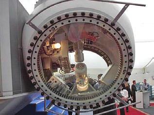
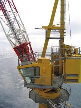
8 Section 1 Introduction Slewing Ring / Turntable Bearings Catalog 390 KAYDON Corporation 2008 Applications - Wind Energy


9 Applications - Medical Slewing Ring / Turntable Bearings Catalog 390 KAYDON Corporation 2008 Section 1 Introduction Photos Courtesy of Varian Medical Systems


10 Section 1 Introduction Slewing Ring / Turntable Bearings Catalog 390 KAYDON Corporation 2008 Applications - Heavy Equipment

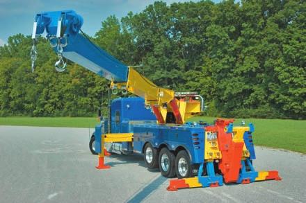

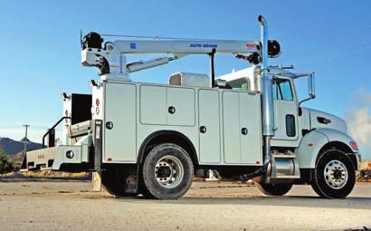
11 Section 1 Introduction


12 Section 1 Introduction Slewing Ring / Turntable Bearings Catalog 390 KAYDON Corporation 2008 Applications - Machinery FMC Jetway Apron Drive Passenger Boarding Bridge Photo by P.Michaud. Courtesy of FMC Technologies, Jetway


13 Applications - Military Slewing Ring / Turntable Bearings Catalog 390 KAYDON Corporation 2008 Section 1 Introduction Image Courtesy of US Army. Image Courtesy of US Army. Image Courtesy of US Army. Image Courtesy of US Navy
14 Section 2 Contents Technical Information & Guide Section 2 Technical Information Page number Function Selection Application Features Properties
15 Technical Information & Guide FUNCTION OF A TURNTABLE BEARING A bearing serves as a connection between two adjacent structures, allowing rotation and transmission of load between them. In addition to satisfying this requirement, a turntable bearing typically includes features for simple and quick attachment to those adjacent structures, and commonly a feature to facilitate the mechanical rotation of one ring and its adjoining structure relative to the other. Kaydon turntable bearings described in this catalog are typically used in applications where their ability to transmit relatively high loads is of primary importance. However, other potential application requirements such as rotational speed, protection from contamination, accuracy, frictional resistance, and the temperature range of the operating environment could have a significant impact in the selection of an appropriate turntable bearing. The following sections discuss application criteria and provide a guideline for selecting a turntable bearing. Upon request, KAYDON is available to assist in the selection of a KAYDON turntable bearing. If such assistance is requested, we suggest that you complete the SPECIFICATION DATA SHEET found in Section 6. SUGGESTED SELECTION PROCEDURE 1. Review the following APPLICATION INFORMATION section before proceeding with bearing selection. The APPLICATION INFORMATION section is a guide for selecting a bearing used in a NORMAL APPLICATION as defined on page Determine the maximum bearing loads. These loads must include all dynamic and static loads imposed on the bearing. The loads in turn must be transposed to loads acting at the bearing s center. See Figure 2-1. Some specific items to consider are: All applied forces to the bearing and gear. Not only the rated and working loads but also those that may occur when equipment is at rest, such as that due to wind for larger structures. Loads imposed during overload or testing situations. Loads imposed during assembly or disassembly. Weights of all members of the structure which are supported by the bearing. All possible combinations of maximum loads. A crane, for example, usually has a number of conditions of load versus working radii, both during use and at time of overload testing. 3. Multiply the calculated loads by the applicable service factor: See page If an integral gear is desired, determine the required gear capacity. As with the bearing loads, consideration must be given to all conditions that would generate potential gear loads; some examples include those while working, static, on incline, and overload testing. One must also consider the duty cycle at each of these conditions. See discussion about Torque on page 15 for assistance in determining bearing rotational resistance. 5. Determine the preferred mounting arrangement, considering the pinion and gear location as well as installation and continued maintenance of the bearing and retaining bolts. See Section Refer to the Product Overview and Selection Guide on pages 4&5, and then the individual bearing style sections for potential bearings. 7. Make a preliminary selection by comparing the previously calculated bearing loads, including service factor, to the bearing s load rating curve. Ensure that all load combinations are below the curve. In many cases there will be a choice of several bearings meeting the required load ratings. 8. If applicable, check the gear rating of the selected bearing. 9. Confirm that the mounting bolts, mounting plates, and joint arrangements are suitable for the installation. See pages 32 to the bearing you select must meet your design requirements. Section 2 Technical Information

16 Technical Information & Guide Section 2 Technical Information APPLICATION INFORMATION LOAD A turntable bearing can be designed for use in applications where loads originate from a single direction or multiple directions relative to its axis of rotation. All of these loads can be resolved into four resultant loads acting on, about, or through the bearing s center. They are referred to as radial, axial, moment and torque. These are used to evaluate the size and capacity of the bearing and integral gear if one is incorporated. Three of these loads are visually depicted in Figure 2-1. The fourth, torque, acts in a manner as to try to rotate one of the bearing rings relative to the other. The result is a lower stress level on all components involved in the transmission of the load. When the axial load is suspended from the bearing, it is concentrated predominantly in a smaller area around the bolts. This is a critical difference that must be considered in the design. See Figure 2-3. Compression axial load Figure 2-2 tension (suspended) axial load Figure 2-3 Resultant forces acting on or about bearing Figure 2-1 Load originated by the equipment and work being conducted is transmitted to the bearing through the mounting structure and mounting bolts. While turntable bearings have the ability to accept all types of load combinations, they are primarily designed for loads aligned parallel to the bearing s axis of rotation. These axial or thrust loads originate from a source located at a distance from the bearing s axis of rotation and also generate a moment load about the bearing s center. Typically, axial loads are applied in a manner that would tend to compress the bearing faces toward each other. See Figure 2-2. Such loads are distributed uniformly around the mounting structures and surface area of the mating bearing rings, permitting a more even load distribution to the rolling elements within. A load aligned perpendicular to the bearing s axis of rotation is referred to as radial. When the radial load originates from a source located above or below the bearing s rolling elements, it generates a moment load about the bearing s center. In applications where radial load is significant (defined as greater than 10% of any axial load) or the predominant load, our standard turntable bearings may require modified contact angles, ball separators, mounting hole configurations, or the addition of piloting diameters to accommodate these forces. SPEED Turntable bearings are generally used where rotational speed is slow, intermittent, and oscillatory. The permissible speed limits for various Kaydon turntable bearings are shown on page 20. ACCURACY The typical turntable bearing application does not require accurate positioning of the rotating structure relative to the stationary one. Therefore all bearings shown in this catalog, excluding the KH Series, are not supplied with diameter tolerances to permit accurate and repetitive positioning
17 Technical Information & Guide Some applications require a high degree of accuracy and are dependent on the bearing to achieve it. Early consultation with Kaydon can lead to use of a turntable bearing furnished with the features necessary to provide the accuracy and repetitive positioning needed. Should a mechanical drive be required, making it integral to the bearing reduces the number of components involved, decreasing tolerance build-up that adversely affects accuracy. TORQUE In most applications of large-diameter bearings, the force required to overcome bearing friction, or resistance to rotation, is small compared to that required to overcome the inertia of the mass being supported provided the bearing is properly mounted and contains the standard internal clearance. Bearings include a minimal amount of clearance to minimize the possibility of tight spots resulting from ordinary imperfections in the mounting. Refer to Section 3 for detailed discussion. A bearing distorted by out-of-flat or out-of-round mounting surfaces may require an excessive amount of turning torque. The same is true for a bearing mounted on a structure which deflects locally under load. Other primary factors affecting bearing friction include contact angle, separator, seals and lubricant. For relatively small loads, the turntable bearing may be rotated manually. However, for applications that involve high loads and torque or where manual rotation is undesirable or impractical, a mechanical means of rotating the bearing and desired mating member can usually be accommodated. Features allowing mechanical rotation of the equipment include gears, sprockets, v-grooves, and timing belt teeth integral to one of the turntable bearing rings. The most common solution is to incorporate a gear on one of the turntable bearing rings as reflected in various bearing series throughout this catalog. This practice eliminates the need for a separate gear and the additional cost and installation requirements associated with it. ENVIRONMENT Turntable bearings are suitable for use indoors or outdoors, where conditions consist of indirect exposure to moisture and contamination, and the temperatures range from -40 F to +140 F (-40 C to +60 C). Operation beyond these temperature extremes may require changes of lubrication and non-metallic material used in the standard turntable bearings. Operation in very dirty or wet environments may require use of additional seals or shields on the mounting structure to limit exposure of the bearing. Coatings To enhance corrosion resistance, KAYDON has the capability to provide a painted surface, a zinc thermal spray coating, or other coatings as specified by the customer. Additionally, we offer ENDURAKOTE plating which provides corrosion resistance and is effective in increasing wear resistance in sliding surface contacts. MOUNTING ARRANGEMENT A widely used method of attaching turntable bearings is to bolt through both races with fasteners spaced uniformly around the entire mounting face. It is recognized, however, that the equipment designer cannot always accommodate this type of arrangement and may require tapped holes and even special bolt patterns for assembly and maintenance reasons. The designer is responsible for the mounting arrangement and validating the design. Weld rings are another option for attaching one of the turntable bearing rings to its mating structure. The bearing is furnished with a low carbon steel weld ring or band welded to one race. The weld ring can then be welded to the machine without damage to the bearing, provided proper precautions are taken. As the use of weld rings is infrequent, they are not addressed in this catalog. For such designs contact KAYDON. Welding the bearing, or welding near the bearing, can damage the bearing. LUBRICATION Grease is the typical lubricant used for turntable bearings. Periodic application of fresh lubricant into the bearing is required to reduce friction and wear, provide corrosion protection, displace contaminants, and enhance performance of the seals. One or more grease fittings or lubrication holes are provided in all turntable bearings for this purpose. Additional lube fittings or holes may be required and can be furnished on request. Whenever the turntable bearing has an integral gear, it too requires periodic application of grease for optimum performance. For further discussion of lubrication see page 44 (Section 3). Section 2 Technical Information
18 Technical Information & Guide Section 2 Technical Information NORMAL APPLICATION Special attention must be given to bearing selection whenever application conditions are different from those considered normal. For a normal application of turntable bearings, the following conditions should apply: Vertical axis of rotation Predominant compressive thrust and moment loading Radial load not in excess of 10% of the thrust load Intermittent rotation with pitch line velocity limited to 500 fpm for single row bearings and 300 fpm for multi-row bearings as shown in this catalog Operating temperature within -40 F to +140 F (-40 C to +60 C) Mounting surfaces machined and reinforced to limit deviation from a true plane to the levels indicated on pages 25 to 31, Figures 3-1 to 3-9 Installation procedure to assure roundness of both races, such as by applying a centered thrust load while tightening the bolts using the alternating star pattern (see Section 3) Provision for periodic lubrication Provision for periodic checking of mounting bolts to verify their proper tension SERVICE FACTORS Refer to Table 2-4 for the appropriate application service factor. The load rating curves shown in this catalog have an application service factor of To determine the required bearing rating, multiply the application service factor by the applied loads on the bearing. Application service factors are based on a number of considerations, but primarily the frequency of use at higher vs. normal loads and potential for extreme or overload. If the intended equipment and application do not appear in Table 2-4, for initial sizing select a comparable application. If there is a question concerning this selection, contact KAYDON. If the application involves more frequent operation than indicated in the above paragraphs and definitive duty cycles for loads, speeds, and oscillation are available, complete and submit the Specification Data Sheet in Section 6. For such applications, the fatigue life of both the bearing and gear may dictate the designs required, and service factors should not be the sole criterion used for selection of a turntable bearing. There is no industry-wide standard for rating the capacity of turntable bearings. As a result, it is not uncommon for bearing vendors ratings and service factors to vary and still result in the same approximate bearing design and size for a given application. Also, these factors may be superseded by customer specification, FEA (Finite Element Analysis) classifications, or regulations by certifying authorities. The equipment designer is responsible for determining the correct service factor. This can be done with the suggestions from and assistance of KAYDON, upon request
19 Technical Information & Guide TABLE SERVICE FACTORS Application Service Factor Aerial Lift Devices Aerial baskets, platforms, ladders, etc Amusement Rides Alternate Criteria * Conveyors 1.00 Cranes Mobile - (loads limited by machine stability) Normal construction duty (tire mounted) 1.00 Normal construction duty (crawler mounted) 1.10 Production duty such as scrap and ship yards 1.25 Forestry handling (logging) 1.50 Stacker cranes (must include dynamic forces as loads) 1.25 Pedestal or Tower - (loads not limited by machine stability) Loads continually monitored by safe load device 1.25 Applications with risk of sudden impact load application 1.50 Offshore Alternate Criteria * Excavators Load limited by tipping 1.25 Load limited by hydraulic pressure relief 1.50 Stacker - Reclaimer Alternate Criteria * Tunnel Boring Machine Alternate Criteria * Hook and Grab Rotators for Cranes Alternate Criteria * Index and Turnstile Tables (include any shock loads for evaluation) Occasional use with intermittent rotation 1.00 Frequent use with intermittent rotation 1.25 Frequent use with intermittent rotation and impact loads 1.50 Continuous rotation Alternate Criteria * Ladle Turrets and Ladle Cars Alternate Criteria * Industrial Manipulators and Robots Occasional service 1.00 Frequent service 1.25 Continuous service Alternate Criteria * Steering Gear (must include dynamic and shock loads due to transit forces) Pneumatic Tires 1.25 Solid Tires 1.50 Water Treatment Clarifiers, Thickeners, and Rotary Distributors Alternate Criteria * Wind Turbines Alternate Criteria * Section 2 Technical Information * As this application involves additional criteria, it requires use of an alternative method for evaluation and selection of the turntable bearing

 and cross roller (XR Series) bearings.")

20 Technical Information & Guide Section 2 Technical Information TURNTABLE BEARING FEATURES INNER AND OUTER RINGS (1 and 2) The bearing consists of an inner and outer ring made of medium carbon steel. Each includes at least one precision raceway arranged to transfer loads and relative motion from one structure of the equipment to the other. The raceways are selectively hardened to the required surface and depth necessary to transmit high stresses imposed during operation of the equipment. Figure 2-5 reflects the typical hardness patterns of fourpoint ball (RK, HS, HT, MT, KH, and XT Series) and cross roller (XR Series) bearings. Multiple row bearings (DT and TR Series) receive similar treatment in their highly stressed raceways. In one location around the raceway, there is an unhardened area referred to as the hardness gap or soft spot. This area is relieved to minimize the ability of the rolling element to apply stress on it. Only one side of each ring is manufactured to be mated with the supporting structure. One or both rings may include an integral drive mechanism such as gear or sprocket teeth to enable the mechanical advantage necessary to overcome rotational resistance and provide relative motion through the bearing. Hardened Pattern for Ball Raceway Figure 2-5 ROLLING ELEMENTS (3) Hardened Pattern for Roller Raceway Precision rolling elements enable relative rotation and transmit load between the inner and outer rings. Hardened chrome alloy steel balls or rollers may serve as the rolling elements. They are sized appropriately for the anticipated stresses and closely matched to provide uniform load distribution between the rings and minimize rotational resistance
21 Technical Information & Guide SPACERS (4) Spacers separate the rolling elements and are designed to minimize friction, skidding, and jamming during rotation. These conditions occur as a result of load distribution and distortion of the mounting structures and bearing rings during operation of the equipment. Spacers are generally made of a plastic material compatible with typical lubricants and operating environments. Occasionally for ball bearings, a ball of smaller size is placed between the larger load-carrying balls instead of a spacer. These are referred to as spacer balls and can provide a solution to a unique condition specific to a particular application. Where the application warrants, a separator is used in place of the spacers or spacer balls. MOUNTING HOLES (5) The ideal hole pattern for attaching both rings of the turntable bearing is a full circle of uniformly spaced through holes. It is recognized, however, that the equipment designer cannot always accommodate this type of arrangement and may require tapped holes and even special bolt patterns in one or both rings for assembly and maintenance reasons. KAYDON has accommodated these special mounting requirements. Samples of these options are shown in Figure 2-6. The equipment designer, manufacturer, or user is responsible for determining if the mounting design is adequate. Some methods employed in making this determination are to perform analysis and then tests to evaluate and validate the structure, fasteners, and joint for adequate strength and integrity to sustain the maximum and all repetitive loads possible. SEALS (6) A seal is included on each side of KAYDON turntable bearings for retention of lubricant and protection of the bearing from dust and small particle contamination. The seals are made of an elastomer material compatible with most general purpose lubricants having mineral oil and greases using lithium or calcium thickeners. If conditions require different sealing, KAYDON can provide details of additional options upon request. LOADING (FILLER) PLUG (7) The rolling elements in KAYDON bearings may be inserted through a hole drilled radially through the non-geared race and then plugged. The plug is retained mechanically with a pin to assure proper orientation is maintained. TR Series bearings, however, do not have a loading plug as they require one of the rings be split for assembly of all the rolling elements. Removal of the load plug voids the warranty. GEAR (8) Turntable bearings can be supplied with gear teeth as an integral part of either the inner or outer ring. They are typically a standard full depth or stub involute spur gear having a 20 pressure angle with provision for backlash and conforming to AGMA Q6 quality. However, where required, modifications of the basic tooth forms, pressure angles, and quality can be provided. For assembly purposes, the maximum point of gear runout is identified with paint. Alternative methods may be applied upon request. GREASE FITTING (9) At least one grease fitting is supplied in one of the bearing rings for periodic lubrication of the raceway and internal components. On designs with integral gear teeth, it is located in the non-geared ring. The number supplied typically increases with bearing diameter. More or less may be included upon request. Section 2 Technical Information Through Hole Threaded Hole Counter- Bored Hole Figure 2-6 Far Side Threaded Hole IDENTIFICATION (10) Identification consists of the bearing part number and serial number. This information is located next to the filler plug
22 Technical Information & Guide Section 2 Technical Information TURNTABLE BEARING PROPERTIES LOAD RATING The majority of turntable bearing applications require the bearing to transmit static load or high loads at slow rotation with operation being intermittent. In such applications, the fatigue life of the internal bearing complement is less of a concern than the bearing s static and infrequent load capability. Most bearing selection is based on the Kaydon load rating chart and an appropriate service factor for the intended application (see Service Factors Table 2-4, page 17). Use of the Kaydon load rating charts requires compliance to all instructions and guidelines provided in the Installation and Maintenance section of this catalog; refer to pages 25 to 44. Failure to follow above recommendations can severely limit ability of the bearing, retaining bolts, and adjacent mounting structures to safely transmit the indicated loads. Load rating charts with a service factor of 1.00 are shown for all bearings listed in this catalog, except for the KH and XR Series. Bearings from either of these series are used where operating conditions and performance expectations require different selection criteria. To further assist the designer in making a KH or XR Series selection, ratings and performance results are provided. If the application involves more frequent operation than indicated on page 16 and definitive duty cycles for loads, speeds, and oscillation are available, KAYDON can assist in bearing selection, upon request. If such assistance is requested, it is recommended that one complete and submit the Specification Data Sheet in Section 6. For such applications, the fatigue life of both the bearing and gear may dictate the designs. As a result, service factors should not be the sole criterion used for selection of a turntable bearing. SPEED The rotation of single-row turntable bearings such as the RK, HS, HT or MT Series should be intermittent and limited to a maximum pitch line speed of 500 feet per minute (fpm). For bearings with multiple raceways such as the DT and TR Series, the maximum pitch line speed should be limited to 300 fpm on an intermittent basis. The KH Series is appropriate to use for continuous rotation at 500 fpm and infrequent rotation up to 750 fpm. Modifications may be made to any of these bearings to permit continuous rotation and load at speeds exceeding the values given. Modifications may include change in internal clearance, contact angle, clearance, rolling element separation, or seals. If assistance is required, contact KAYDON for a bearing to meet your specific requirements. ACCURACY All turntable bearings shown in this catalog, with the exception of the KH Series, are furnished with sufficient internal clearance to allow for some imperfections of mounting surfaces and for small amounts of deflection under load. They are not furnished with external diameters having a low tolerance to permit accurate positioning of the rotating structure relative to the stationary one. Upon request, Kaydon can supply bearings with reduced clearance or preload, reduced runout, and external diameters for location purposes. The KH Series is provided with no internal clearance and closely held external diameters for those applications requiring additional accuracy. See page 72 for additional information concerning accuracy of the KH Series. If necessary, bearings can be furnished with reduced internal clearance to minimize rock. Extra care should then be taken to assure the installed bearings will be round and flat to maximize bearing capacity and performance. See pages 25 to 31 (Installation & Maintenance). Our standard integral gear is manufactured in accordance with AGMA Class Q6 quality, excluding the KH Series. Should the application warrant, gears can be supplied to AGMA Class Q11 quality. The integral gear supplied on the KH Series is in accordance with AGMA Class Q8 quality

23 Technical Information & Guide ROTATIONAL FRICTION (TORQUE) The friction torque for a turntable bearing due to external loads can be estimated using the following equation. This assumes the bearing is mounted according to the guidelines provided in the Installation & Maintenance Section, pages 25 to 44 of this catalog. This is an estimate and is significantly influenced by fluctuations in critical features; therefore, it is advisable to account for additional torque when initially selecting the drive arrangement. Once some experience with the application has been accumulated, the drive arrangement can be altered accordingly. Also note, the equation is not valid when the application loads equal zero, as there will still be some rotational resistance due to the weight of the rotating components and frictional resistance of the seals and lubricant. M w = μ (4.4M k + F a D p + 2.2F r D p ) 2 Where: M w = bearing torque under load, (ft-lbs) µ = friction coefficient =.006 for RK, HS, HT, MT, KH, XT, and DT Series =.004 for XR and TR Series M k = moment load, (ft-lbs) F a = axial load, (lbs) F r = radial load, (lbs) D p = bearing pitch diameter, (ft) GEAR RATING Tangential gear tooth ratings are shown in the selection tables for each applicable bearing and gear combination. These ratings only consider bending fatigue strength being generated using the commonly accepted Lewis Equation. They are suitable for sizing when the application involves low speed and intermittent/oscillatory rotation. For applications with higher duty cycles, or frequent and rapid acceleration it may be necessary to use alternative methods, including surface fatigue for determining adequacy of the gear tooth design. As a precaution it is recommended the machine designer verify the adequacy of the gear based on his own methods of calculation and past experience. When additional surface endurance and bending strength are required, KAYDON can accommodate both by providing a gear with rounded fillet and selectively hardened flanks and root. See Figure 2-7. On occasion and where the application permits, a gear with only the tooth flanks hardened may be used. This increases tooth surface endurance, but may decrease the tooth bending strength depending on the initial and final configuration being evaluated. Selective Hardened Flanks and Root Figure 2-7 Section 2 Technical Information


24 Section 3 Installation & Maintenance
25 Section 3 - Installation & Maintenance The following instructions provide essential information for the proper application, installation, and maintenance of KAYDON turntable bearings. These instructions are divided into sections according to each of these disciplines and must be performed by qualified personnel. Failure to adhere to these instructions may significantly impair the turntable bearing s ability to provide satisfactory service and may cause premature failure of the bearing as well as endanger safety of any personnel in the vicinity of the equipment. Technical properties of turntable bearings are covered in Sections 2 and 4 of KAYDON 390 Catalog. KAYDON accepts no liability for: 1. Non-compliance to instructions provided in this Installation and Maintenance literature. 2. Failure to pass on content to third party. Section 3 Installation & Maintenance
26 Section 3 Contents Installation & Maintenance Section 3 Installation & Maintenance Page number Part 1 - Design Considerations (For Equipment Designer) Mounting Structure Stiffness Interface Features Flatness Pilots Holes Protection Access (For Installation and Maintenance) Attachment Bolts Welding 1.2 Pinion and Gear Mesh Pinion Design Considerations Backlash 1.3 Mounting Examples Part 2 - installation and Maintenance (For Equipment Builder) Handling 2.2 Storage 2.3 Installation Preparation Positioning Securing Gear Backlash and Alignment 2.4 Post Installation 2.5 Maintenance Lubrication Bearing Gear Bolts Seals Cleaning Noise, Roughness, Vibration Torque Tilt (Clearance) Dismantling and Disposal Part 3 - Maintenance (Guidance for Equipment Owner and/or User) Before Use 3.2 During Use 3.3 Grease Lubricants Table
27 Installation & Maintenance 1. Design Considerations (Guidance for the Equipment Designer) Turntable bearings, due to the nature of their design, have low structural stiffness making them highly susceptible to any distortions caused by the surrounding structures. Such distortions cause variations to the precisely designed and manufactured internal geometry of the bearing and will adversely affect performance and life. 1.1 Mounting Structure Most component designs are a necessary compromise from the ideal to the practical. The design of mounting structures for large multiload bearings is no exception. Regardless, several criteria must be satisfied by the mounting structures, above and below the bearing, in order to obtain maximum bearing life and performance. Among these are stiffness, attachment, precision, accuracy, protection, and access. The requirement for increased stiffness and higher precision surfaces is more critical under the following conditions: Increasing loads Increased frequency of operation Decreasing diameters Decreasing bearing cross sections Decreasing internal bearing clearance Decreasing torque limits Protection of the bearing and accessibility for maintenance are critical to ensure bearing performance and longevity. The following guidelines make reference to the bearing's rolling element diameter (D w ) and raceway diameter (D p ). During initial stages, the designer can use the following approximations. As required, contact KAYDON for the specific bearing assembly drawing for confirmation of the raceway diameter and other important design features. D w 0.5 H min D p 0.5 ( L 0 + L i ) KAYDON recommends steel to fabricate any structures used in conjunction with its turntable bearings, unless otherwise specified. The actual steel material selected will vary as required by the final structure design and resulting stresses. The use of higher strength steels does not necessarily result in increased stiffness. The choice of material for the structure is the equipment designer's or manufacturer's Stiffness The ideal bearing mounting would be infinitely rigid and isolate the bearing from localized loads and distortion. Recognizing this to be impractical, while still maintaining the original equipment design goals, KAYDON prepared Figures 3-1 to 3-3 (Deflection) showing maximum permissible deflections that typical four-point and eight-point ball bearings can withstand while maintaining correct function. Allowable circumferential deflection ( d d ) around the structure s mounting face is shown in Figure 3-1. There must be no abrupt changes in deflection. The maximum deflection error must be gradual, similar to a sinusodal wave pattern, and not occur in a span less than 90 and not more than once in 180. Another consideration is the allowable deflection from a true plane in a radial direction ( d v ), also referred to as dish or perpendicularity. For ball bearing designs this can be determined by using the following equation. d v D w P Where P = radial distance of mounting structure face The maximum deflection for roller bearing designs is 2/3 of that for the equivalent sized four-point ball bearing. Reduction of the d d and d v values may be necessary due to certain application requirements such as lower rotational resistance or higher precision. Equipment designs not complying to these requirements will adversely affect bearing performance, imposing concentrated loads on the bearing and adjoining fasteners. Concentration of loads results in higher loads on the rolling elements, raceways, and adjoining fasteners. This will lead to increased rotational resistance, decreased bearing and fastener life and a potentially unsafe working environment. Section 3 Installation & Maintenance
28 Installation & Maintenance ALLOWABLE DEFLECTION VS RACEWAY DIAMETER Must not occur within 90 nor more than once in 180 of circumferential travel.120 Section 3 Installation & Maintenance Allowable Deflection Deviation d d - (in) Ball.75 Ball 1.5 Ball 2.0 Ball 2.5 Ball 3.0 Ball Raceway Diameter D p - (in.) Figure 3-1 PERMISSIBLE DEVIATION RATE Permissible Deviation d d and d r Max. Value Permissible Curve 0 Circumferential Direction 180 Deg Figure


29 Installation & Maintenance Circumferential d d and d r Radial d v and d p Radial Distance P d v and d p d d = circumferential deflection d r = circumferential flatness KAYDON offers the following guidelines to assist designers. Failure to follow any of these may cause additional risk and/or premature failure. Therefore, testing of the overall configuration and bearing installation is required to validate the design. Extra caution is required during any testing, as failure of any component could lead to complete separation. This may result in injury or fatality to anyone in close proximity. A uniform vertical and tube-shaped structure with a flange on one end should be used, allowing adequate room for fastener installation and maintenance. This structure would be similar to the end of a flanged pipe with a diameter close to that of the bearing's raceway. Refer to Figure 3-5. For initial sizing, wall thickness of such tubing should be at least 1/5 the overall height of the adjacent bearing's ring. Refer to Figure 3-4. The mounting or structural plate supporting the bearing should have a finished thickness of 1/2 of the bearing ring height for single-row rolling element bearings and at least 1/3 of the bearing ring height for multi-row bearings. Generally, thinner mounting plates require more structural support and bracing to stiffen the overall design. The final thickness of plate required will vary depending on the overall configuration of the structure and load being applied. Testing, as mentioned above, is recommended. The face of the structure that supports the bearing must make contact with the complete mounting face of the bearing's ring and have surface finish 250 AA or better. Mounting Structure Deviations Figure 3-3 d v = radial deflection d p = radial dish (perpendicularity) Obtaining a uniform distribution of the load to the bearing is difficult when using a frame, welded structure, and gussets for structural support under the mating plate. Should it be necessary to use such a design, the frame and supporting structure must be oriented to provide as much support as possible directly below the bearing's raceway. Refer to Figures 3-6 and 3-7. If the immediate structure supporting the bearing consists of two plates, one welded atop the other, caution must be taken to avoid distortion of the plates during welding as it could result in undetected voids between them. Under load, the plates will deflect causing non-uniform and increased dynamic loads on the bearing and retaining bolts. Refer to Figure 3-8. Variation in the physical "grip length" of the bearing's mounting bolts is not permissible in the design of the mounting structure. The physical "grip length" is the distance from the bottom of the bolt head to the first thread of engagement. Such variation imposes a disproportionate amount of load on those having shorter grip length. This can lead to premature failure and/or separation of the assembly. Special attention needs to be given to stiffness of the gear drive mounting area. Designs having insufficient rigidity in this area will permit deflection and result in poor gear and pinion mesh alignment. Poor alignment can lead to premature failure of the pinion, gear, and gear drive. Section 3 Installation & Maintenance

30 Installation & Maintenance Section 3 Installation & Maintenance MINIMUM MOUNTING SUPPORT REQUIREMENTS Figure 3-4 VERTICAL TUBE WITH FLANGE FOR MOUNTING SUPPORT Figure


31 Installation & Maintenance Frame without gussets near mounting holes requires thicker plate. Gussets added near bearing mounting holes increase rigidity. FABRICATED FRAME & STRUCTURE SUPPORTS Figure 3-6 Gussets added near mounting holes and ring replace plate for additional rigidity. Section 3 Installation & Maintenance Turnstile without braces lowers side plate and mounting plate rigidity, reducing load distribution around bolt pattern and bearing. Turnstile with braces increases side plate and mounting plate rigidity and provides increased load distribution around bolt pattern and bearing. Turnstile with braces located near bolt mounting holes increases side plate and mounting plate rigidity and provides additional load distribution around bolt pattern and bearing. FABRICATED TURNSTILES Figure

32 Installation & Maintenance Section 3 Installation & Maintenance Interface Features WELDED PLATES - POTENTIAL FOR DETRIMENTAL DISTORTION Flatness Bearing mounting surfaces must be machined flat after all welding and stress relief treatment on the structures is complete. If subsequent welding is necessary, it must be done to avoid distorting the previously machined mounting surface. The allowable degree of out-of-flatness in the circumferential direction ( d r ) for typical four-point and eight-point ball bearings is shown in Figure 3-9. Outof-flatness, like distortion, must be gradual, reflecting a sinusodial wave pattern and not occur in a span less than 90 and not more than once in 180. In addition to flatness in the circumferential direction, Figure 3-8 the allowable dish or perpendicularity deviation ( d p ) in the radial direction must be determined. For ball bearing designs, this can be done using the following equation. d p D w P Where P = radial distance of mounting structure face The maximum out-of-flatness for roller bearing designs is 2/3 that shown for the equivalent sized four-point ball bearing. It may be necessary to reduce the d r and d p values in applications which require low rotational resistance or high precision
33 Installation & Maintenance ALLOWABLE FLATNESS VS RACEWAY DIAMETER Must not occur within 90 nor more than once in 180 of circumferential travel Ball Allowable Flatness Deviation d r - (in) Ball 2.0 Ball 1.5 Ball 1.0 Ball.75 Ball Section 3 Installation & Maintenance Raceway Diameter D p - (in.) Figure 3-9 KAYDON does not recommend the use of grout or shims to compensate for excessive out-offlatness Pilots Pilots are sometimes used for accurate location of the bearing or to aid in retention of the bearing. If used, they must be round and accurately sized so that they do not distort the bearing. Consideration must also be given to their eccentricity and positioning tolerance relative to any hole patterns used in the structure and the interfacing bearing ring. KAYDON can provide the applicable bearing assembly drawing which includes interfacing tolerances Holes Mounting holes and dowel holes, if any, must be within the true location tolerances required to prevent distortion of the bearing due to interference. Mounting hole location tolerance must account for eccentricity of the hole pattern relative to any pilot diameters. Through holes should be compatible with the location tolerance and of a diameter equivalent to those in the corresponding bearing ring. KAYDON can provide the applicable bearing assembly drawing which includes interface features and tolerances. Bearings should never be used as drill jigs. They may be used as templates for transfer of hole location provided care is taken not to distort the bearing. Distortion is more likely to occur on bearings having thinner ring sections Protection KAYDON bearings are designed to withstand normal operating environments. If the upper structure does not provide complete cover for the bearing, a separate seal or shield is recommended. Exposed gears should be shrouded if they are to be exposed to extremely dirty conditions. Shields and shrouds should be designed with cover doors, plugs, or other means of access to the bearing for maintenance purposes. To further enhance protection, KAYDON can provide painting or plating options as required
 Like all mechanical components on a machine, the bearing must be accessible so that it can be properly maintained. The following must be considered.")
34 Installation & Maintenance Section 3 Installation & Maintenance Access (For Installation and Maintenance) Like all mechanical components on a machine, the bearing must be accessible so that it can be properly maintained. The following must be considered. Mounting bolts require periodic checking and possibly retightening. Access to every mounting bolt must be readily available. Failure to properly maintain the mounting bolts may result in failure and injury to anyone in the vicinity. Lubrication of the gear and internal components is required and convenient access to the gear and bearing grease fittings must be provided. It is recommended that remote lines to the bearing be added to allow rotation as grease is introduced to the raceways. There may be rare occasions when it is desirable to inspect the bearing raceways and internal components. This should only be attempted by qualified personnel due to the potential for the bearing and structures to come apart. This can damage components and cause injury or fatality to anyone in the vicinity. This inspection may be accomplished on typical turntable bearings by removal of the loading plug, excluding three-row roller designs. While removal of the loading plug voids the warranty, it may be necessary. To accommodate access to the retention pin for the loading plug, the designer should include additional clearance or access holes above and below the retaining pin. See Figure ACCESS HOLES FOR LOADING PLUG Attachment Figure 3-10 The method of attachment of KAYDON bearings to the support structure significantly affects its design. The preferred method is to use bolts in both rings. If you require assistance with applications where the attachment for one ring is to be done by welding, contact Kaydon Bolts The preferred bolting arrangement is a full circle of uniformly spaced fasteners going through holes in both bearing races. This benefits both the bearing and the bolts. The bearing races are reinforced by the bolt tension. The resulting greater bolt grip length allows more accurate and uniform pretension, reducing fatique loading. However, it is not always practical to have all the mounting holes spaced exactly equal on all designs, due to interference with supporting structures or brackets. In such cases, the spacing between adjacent bolts may be shifted a few degrees either way to accommodate mounting hardware and assembly. Testing is recommended, as it is the only accurate method for determining bolt loads and validation of the overall joint configuration and assembly procedure
35 Installation & Maintenance The bolt arrangement, quantity, size, and thread engagement of bolts are the responsibility of the equipment designer and manufacturer for the following reasons: There is no universally accepted method of analyzing the forces imposed on the bolts in a turntable bearing joint subjected to moment loading. The stiffness, uniformity, and final design of the structures to which the bearing is attached have an extremely high degree of influence on the load in the fasteners. Only the equipment designer or manufacturer can control this. The quality of the fastening hardware, method of tensioning, hardness of the surfaces under the bolt heads, and the use of thread lubricant are critical factors over which the equipment manufacturer has control. We suggest that selection of the bolts should be made with the advice and assistance of the fastening hardware supplier, as bolt quality and recommended method of pretensioning and maintenance vary widely. Attention to details such as head/body fillet radius, thread form, finish, surface asperities, and freedom from cracks and other possibly fatal flaws are very important to the safety of the equipment and any personnel in the vicinity. The importance of adequate and uniform pretensioning is evident from the proliferation and technological advancement of devices such as: Turn of the nut indicators Preload indicating washers Torque wrenches with integral yield sensors Hydraulic bolt stretchers Ultrasonic measuring equipment To aid the designer in initial sizing, the following formula can be used to calculate the approximate load on the heaviest loaded bolt. This method is based upon past experience and yields results that have proved satisfactory for most applications. It is analogous to the method Kaydon uses to determine the load on the heaviest loaded rolling element within a bearing. Kaydon makes no warranty, expressed or implied, regarding the adequacy of the bolts. The only certain way to determine the actual load is by testing, which is strongly recommended. R b = 12 M k F f ± F a L n n *F s = Bolt Proof Load Rating R b M k = Moment load, (ft - lbs) F f = Flexibility factor. Use 3 for bearings and support structures of average stiffness. F a = Axial load, (lbs) L n If the load is in tension, the sign is +. If the load is in compression, the sign is. Refer to Figures 2-2 and 2-3. = Bolt circle diameter, (in) = Total number of evenly distributed bolts R b = Total load on heaviest loaded bolt, (lbs) *F s = Factor of safety of bolts. Minimum recommended value = 3 Bolt Proof Load SAE J429, Grade 8 and ASTM A490; Coarse Threaded Series Bolt Dia. (in) Proof Load (lbs) 1/2 17,000 5/8 27,100 3/4 40,100 7/8 55, , /8 91, /4 116, /2 168,600 Section 3 Installation & Maintenance
36 Installation & Maintenance Section 3 Installation & Maintenance If you determine that alteration to the mounting hole pattern is required for your bearing, KAYDON is available to provide assistance to help you select a mounting hole pattern for the bearing in question. The following is a list of additional recommendations concerning bolts and their incorporation into the final equipment design. The items listed below are not all inclusive and further study on the subject is recommended. These recommendations are intended to provide the designer with a good basis from which to begin. High strength bolts with coarse threads and hexagon heads in accordance with SAE J429, Grade 8 or ASTM A490/A490M or ISO 898-1, Grade 10.9 tensioned to 70% of their yield strength. Where applicable, coarse threaded hex head nuts in accordance with SAE J995, Grade 8 or ASTM A563, Grade DH or ISO 898-2, Class 10. Hardened round flat steel washers in accordance with ASTM F436 under head of bolt and also nut. Use of hardware that identifies the manufacturer as well as proper SAE, ASTM or ISO grade designations. The ratio of the joint's clamp length (distance from the bottom of the bolt head to the first thread of engagement) to the nominal bolt diameter should equal 3.5 or greater. This ratio has a significant impact on embedment and the potential for loss of bolt tension and premature failure. A higher ratio is less prone to result in loss of bolt tension Lower ratios may prove unacceptable and require more frequent inspection of the bolts for proper tension. Testing is required for validation. Bolt threads should end short of the head by at least a distance equivalent to the body diameter. Equal clamp or grip length for all mounting bolts in a given ring. The thread engagement length between bolt and mating steel structure should be at least 1.25 times the nominal bolt diameter. A bolt should be used in every mounting hole. There should be a minimum of 6 free threads (not engaged) in the tensioned portion of the bolt. Performance of bench tests is recommended to validate that the method of bolt tensioning achieves the desired results prior to any equipment testing. High strength socket head bolts (ASTM A574) are not preferred but have been successfully used in turntable bearing applications. These high strength bolts have a smaller head diameter which requires less space; however they also have less surface area under the head. This reduced surface area increases the potential for more variation in final bolt tension due to embedding and settling. High strength socket head bolts must be used in conjunction with a hardened washer and nut. The nut should be turned to achieve final bolt tension. If possible, use a hardened washer under the head as well as with the nut, to minimize embedment, settling, and loss of bolt tension that could result in premature bolt failure. Calibrated tension indicating washers are acceptable. Lockwashers are NOT recommended, because of potentially significant variations in frictional resistance, embedding, and loss of bolt tension leading to permature failure of the bolt. Additionally, locking compound on the threads, intended to prevent loosening, is NOT recommended. As mentioned in the maintenance section, the bolts require frequent inspection for proper tension. The most common method used to fulfill this requirement is measuring torque of the bolt. The use of locking compound can lead to a false conclusion that the bolt has the desired tension. Loss of the proper tension can lead to premature bolt failure, dismounting of the bearing and structure, damage to components, and injury or fatality to anyone in the vicinity
37 Installation & Maintenance Welding Attachment of bearings by welding is not favored and is limited to new applications in unusual situations. If additional assistance is required, we suggest that you contact the KAYDON Engineering Department for these applications. 1.2 Pinion and Gear Mesh Pinion Design Considerations If a bearing with an integral gear has been selected, the machine designer should work with a pinion manufacturer to select the appropriate mating pinion. It is important to be aware and consider all potential operating circumstances which could be detrimental to pinion and gear life. A pinion supported only on one end is often selected for mating with turntable bearings. This is commonly referred to as an overhung pinion. Use of this type of arrangement whenever high gear tooth loads exist requires the designer to consider pinion modifications not commonly used with standard gear transmissions. We suggest that the following gear design modifications should be considered when selecting a mating pinion. Addendum modification (profile shift). This is especially important for pinions having fewer than 15 teeth for a Stub Involute tooth form and 19 teeth for a Full Depth Involute tooth form to avoid undercut, weakened tooth design, and to avoid tip or involute interference. Profile and tip relief. Refer to Figures 3-11 & Higher dynamic loads, fewer pinion teeth, and support only on one end of the pinion increase potential for deflection of the gear and pinion teeth during operation. These conditions have a tendency to generate wear (scuffing) in the dedendum of the gear tooth, regardless of the teeth having correct profiles and theoretically compatible geometry. Scuffing generates metallic wear particles and weakens the gear tooth. This may prove detrimental to gear and pinion life depending on the operating circumstances. Crowning or changing of the tooth thickness along its width. This is considered a good practice for highly loaded gears as it allows better distribution of the stresses along the tooth face. For situations with over-hung pinion mounting, off-setting the crown should be considered to account for pinion and drive deflections and provide a more even stress distribution. Generally the thickest section along the tooth face is off-centered toward the unsupported end of the pinion. Surface hardening of the pinion. The pinion experiences more operating cycles than the gear teeth. Therefore, it requires a higher surface endurance life. This is accomplished by through hardening or selective hardening. When through hardening, care must be taken to prevent the pinion teeth from becoming too hard and brittle for the intended application and mating gear. Selective hardening of the pinion is an alternative when surface hardness and ductility are major design concerns. A hardness pattern that ends in the fillet area has significantly less strength than one that flows completely around the fillet and up both flanks. The heat treat methods to accomplish this include carburizing, nitriding, or induction hardening. In all cases, evaluation of the hardness pattern, including the transition area, is necessary to determine if it is appropriate for the intended use. Quality The pinion quality should be equivalent to or better than that of the mating gear. Section 3 Installation & Maintenance Scuffing on Dedendum Figure 3-11 Flank Tip and Profile Relief Figure

38 Installation & Maintenance Section 3 Installation & Maintenance Backlash Backlash is required for most geared turntable bearing applications. This is to accommodate manufacturing tolerances of the gears, mounting structures, lubrication, thermal expansion, and deflection of the components under dynamic loading. Refer to Figure Gear Assembly Backlash Figure 3-13 In high ratio gearing, the larger of the two mating gears usually has its teeth thinned to accommodate this, and the smaller one is kept at nominal to maximize its tooth strength. The amount of tooth thinning, or backlash allowance, is shown on Kaydon s drawings, which may be obtained by contacting Kaydon. Typical backlash ranges are shown in Table For module gears, use the approximate equivalent gear pitch diameter and diametral pitch as shown in the table. The backlash should be measured just inside each end of the pinion and gear mesh to verify that proper alignment is obtained. Poor alignment can result in premature tooth wear and breakage. Consider any crowning of the pinion teeth when evaluating the alignment. m = 25.4 = module P d The designer or manufacturer needs to determine whether to use a fixed or adjustable center distance. Factors that influence this decision are skill level of assemblers, installation time, maintenance, and economics. The designer must also weigh potential for increased gear life versus additional cost incurred by requiring more stringent manufacturing tolerances or designing for an adjustable center distance. Gear Pitch Dia, D 2 (in.) Minimum Backlash, J (in.) Table 3-14 Maximum Backlash (in.) Diametral Pitch (P d ) , 4,


39 Installation & Maintenance 1.3 Mounting Examples KAYDON bearings can be designed to suit a number of mounting arrangements. Following are illustrations of some basic arrangements. These can be varied to suit the requirements of a specific application. Such variations include types of holes, location and number of lube holes, omission of integral gears, and incorporation of special seals. Figure 3-15 Pinion is attached to stationary outer race support and rotates the upper structure supported by the inner race. A shroud over the outer seal and bolts prevents contamination under extreme conditions. The mounting structures shown are intended to be illustrative only. Important details in design such as mounting plate thickness, location and number of stiffening members, and bolt lengths must be determined by the equipment designer as detailed in previous sections. Figure 3-17 Pinion is attached to rotating upper structure carried by outer race. Location of gear on inner ring provides protection from harsh external conditions. Section 3 Installation & Maintenance Figure 3-16 Inner race supports the rotating upper structure with pinion. An external shroud protects the gear teeth on the stationary outer race. Figure 3-18 Pinion is attached to stationary inner race and rotates geared outer race carrying upper structure
40 Installation & Maintenance Section 3 Installation & Maintenance 2. installation and Maintenance Considerations (Guidance for the Equipment Builder) 2.1 Handling Turntable bearings, like any other machine part, require careful handling. Use of safe operating practices and observation of all relevant legal regulations when handling, cleaning, and transporting are required. It is recommended that gloves be used whenever handling the bearing. Transport the bearings only in the horizontal position, preferably safely secured to shipping pallets or in a container. When lifting a bearing, use eye bolts in the mounting holes or nonmetallic slings at three evenly distributed points around the bearing. Avoid any sudden acceleration or impact. If the bearing must be turned over, use nylon web slings or equivalent. Do not use chains or metallic mesh slings in contact with the bearing. 2.2 Storage KAYDON Turntable bearings are packed with general purpose grease at the factory, unless specified by the customer, and are sealed to exclude ordinary foreign matter. Keep the bearing packaged as originally received and in a horizontal position until all preparations have been made for its installation. If it is necessary to stack the bearings, then a stable intermediate layer with adequate strength to support the weight must be used between bearings. The overall stacked height must not exceed three feet. We recommend that you do not stack more than two high if the bearing is four feet or larger in diameter. Outdoor storage is not recommended. If the bearing is not installed within one year of receiving it, the grease should be purged and replaced with fresh grease. External surfaces of turntable bearings, including the gear, are coated with a preservative oil to provide nominal protection during storage. We suggest that you advise KAYDON if extended periods of storage are anticipated so that the bearings can be packaged appropriately. 2.3 Installation It is important to recognize the vital role of the bearing/gear and the means for securing it to the equipment, whether it be with bolts or welds. Detailed and clear instructions need to be prepared for the installer. When bolts are used as the means of attachment, tests need to be conducted to validate that the method of bolt pretensioning achieves the desired results. Confirm the bolts have the proper quality standard and manufacturer identification as prescribed by the designer. If the bearing is to be attached by welding, conduct the necessary tests to prove that the specified joint will be strong enough to safely attach to the bearing. Examine for and remove weld spatters, nicks, and burrs. If surfaces have been painted, remove the paint completely Preparation Installation of the bearing and gear assembly should be done in a clean, dry, well-lit area. Mounting surfaces and pilots of the housings should be machined, unpainted and wiped clean of chips, dirt, and lint, since even trapped soft material will act as high spots. When this has been done, examine for and remove weld spatter, nicks and burrs and wipe clean again. The mounting faces need to be machined and in accordance with the limits prescribed in Part 1, Paragraph Confirm that the bearing and all necessary and correct hardware are on-site before beginning the installation. Verify the bolts and mounting hardware are of the size, design, finish and quality specified by the designer. The bolts must have proper identification for the quality standard required. Using bolts that are not in conformance with those prescribed can lead to unsatisfactory bearing performance, premature failure, and a potentially fatal working environment. Refer to Part 1, Paragraph

41 Installation & Maintenance Positioning If one ring has a pilot or dowel hole, it should be positioned and mounted first. Consider alignment of gear's minimum backlash on structure so any necessary adjustments can be made. Identify zones of maximum load on supporting structures to which the bearing will be secured. When in doubt, consult with the equipment designer for their instructions. Examine and identify any damage to packaging prior to unwrapping the bearing; then it should be wiped clean and inspected. Do not expose the seal area or any other bearing opening to pressurized cleaning. Use only cleaning material that is compatible with the seal material and avoid getting debris or other material into the bearing. Visually inspect and confirm that there is no damage to the bearing, gear, seals, or grease fittings. Remove any minor burrs from mounting surfaces that may have occurred in shipping or handling. Use a hand file, taking care to remove only as much material as necessary to ensure full contact of bearing surface with equipment mounting surface. Make sure all surfaces are wiped clean. We recommend that the bearing not be disassembled without express approval of and instruction from KAYDON. Removal of the loading hole plug voids the warranty. Lift or hoist the bearing into position, placing intended ring down on its supporting structure. Align the mounting holes and orient the ring so the load plug and/or hardening gap location (identified by a G ) is 90 from the most heavily loaded zone. Confirm the grease fittings or holes are located for easy access, or aligned with lubrication lines. Using a gauge, verify the bearing is fully supported by the mounting structure. If not, then determine cause and correct Securing For good load distribution and smooth, low torque operation, the bearing should be as round as possible when the bolts are tightened. The following procedure is provided as an aid in achieving that objective. Install washers, nuts, and hand tighten bolts in the supported ring according to the instructions from designer. Make sure there is no interference or rubbing of the bolts in any of the holes. Do not distort the bearing in order to insert any bolts. Interference can cause inaccurate results and lead to premature failure of bearing and bolts. Apply a moderate centered thrust load to the bearing and note the torque required to rotate the bearing. Tighten all bolts in accordance with the equipment designer s instructions. Failure to follow the equipment designer s instructions could result in premature wear or catastrophic failure of the bearing and result in damage to equipment, personal injury, or death. A common method is the use of star pattern tightening following the sequence below. This is usually done in 3 steps at approximately 30%, 80%, and 100% of the final torque or tension level prescribed by the equipment designer. Section 3 Installation & Maintenance Figure

42 Installation & Maintenance Rotate the unsecured bearing ring several times after each step, checking for tight spots or a significant increase in torque over that initially noted. Either of these indicates the bearing is distorted. Determine and correct the cause. Remove the centered thrust load previously applied to the bearing and prior to securing the other ring. Section 3 Installation & Maintenance Position the other bearing support structure on the unsecured bearing ring. This support structure should have minimal number of components attached, to keep weight and moment load low so the bolt tensioning operation is not adversely affected. Align mounting holes and orient the ring so the load plug and/or hardening gap location (identified by a G ) is 90 from the most heavily loaded zone. Using a gauge, verify the bearing fully supports the mating structure. If not, then determine cause and correct. Insert and tighten bolts in second ring as done for secured ring. Continue to rotate and check bearing for tight or excessive torque during this operation. Complete installation of all rotating components of significant weight, and check bearing for freedom of rotation. Excessive torque level, variation, or vibration is indicative of some unsatisfactory installation condition or component. As permitted, inspect seals again for any damage Gear Backlash and Alignment After mounting the bearing, mount the mating pinion. Check backlash of the gears. Pinions on adjustable centers should be set for proper backlash. Do this at point of minimum backlash on the gear, identified with yellow paint in the tooth space, and at both ends to confirm prescribed alignment exists. If either of these is not as prescribed by the designer, determine and correct the cause. Refer to Figure Post Installation Gear Backlash Figure 3-20 When the equipment has been completely assembled, and prior to testing, check bolt tension to ensure that it is in compliance with that specified by the designer. The equipment should be oriented to generate as little moment or radial load on the bearing as possible to avoid inaccuracy in readings. Document this orientation so it may be used for all future bolt inspections. Any loss of pretensioning must be determined and eliminated. Measure and record initial bearing tilt (clearance) of equipment following guideline provided in Paragraph During and after validation testing, check bolt tension with equipment orientation as previously done and documented. Any loss of pretensioning must be determined and eliminated. Follow Paragraph for lubrication intervals of bearing and gear during testing. Relubricate the bearing and gear prior to delivery of the machine. Introduce fresh grease into the bearing until grease is observed coming from under either seal. Rotate the bearing several times to ensure a complete fill. Repeat every 6 months on idle equipment or as recommended by the equipment designer
43 Installation & Maintenance 2.5 Maintenance While KAYDON turntable bearings require minimal attention, what little they are given will pay big dividends in long life, high performance, and troublefree service Lubrication Bearing Lubrication of the bearing is recommended every 100 operating hours for relatively slow rotating or oscillating applications such as backhoes, excavators, and cranes or as specified by the designer. In more rapidly moving or continuously rotating machinery such as trenchers, borers, and material distributors, the bearing should be lubricated every day, or every 8 hours of round-the-clock service. Refer to Section 3, page 44 for futher discussion on lubricants to use. Idle equipment should not be neglected. Grease dries out and breathing, due to temperature changes, can cause condensation within the bearing. Whether used or not, the bearing should have grease introduced every 6 months. The bearing should then be rotated a few revolutions to coat all surfaces with fresh grease Gear There is a tendency to take much better care of the bearing than the gear. However, the meshing action and usual position of the gear tends to purge the lubricant; thus, the gear should be regreased frequently with a small amount of lubricant. A wellmaintained gear will provide long, smooth, and quiet service. It is recommended that grease be introduced at the point of mesh of pinion and gear every 8 hours of slow or intermittent operation, and more often for rapidly or continuously rotating applications. Refer to Section 3, page 44 for further discussion on lubricants to use Bolts The cyclic nature of loading on the mounting bolts gives rise to the possibility of their working loose or to inelastic deformation of the threads and other stressed surfaces. With the equipment in the same orientation as the initial testing during installation, the bolts should be checked by the end user within the first 200 to 300 operating hours. Should any loss of pretension be detected, the source must be determined and eliminated. The bolts should be checked again after each additional 200 to 300 hours of operation until loss is no longer detected, at which time the inspection frequency can be extended as specified by the designer Seals Seals should be inspected during routine maintenance as recommended by the designer, but the interval should not exceed 6 months. Check for tears, breaks, or other signs of damage. Depending on the lubrication frequency and protection, it may be necessary to clean some areas to conduct this inspection. Carefully remove any buildup of debris around the seal and lubricate the bearing. There should be a small bead of grease around the seal edge indicating the bearing is receiving sufficient lubrication Cleaning Cleaning should be done with material compatible with seals following all manufacturers' instructions for use, storage, and disposal. Take precautionary safety measures and use safe operating practices, observing all relevant legal regulations when handling. Do not expose the seal area or any other bearing opening to pressurized cleaning Noise, Roughness and Vibration Continued monitoring of equipment noise, roughness, and vibration during operation can assist in early detection of poor or unsafe components, structural failure, or poor bearing performance. The operator should be very familiar with the typical operating conditions generated by the equipment. Investigate and resolve any noted changes Torque Monitoring rotational torque and any variation can not only be used to determine a bearing's condition, but can also provide early indication to a gear, joint, or other structural problem. To determine any change in torque, it is first necessary to record an initial measurement best done after testing and prior to the equipment going into service. Check torque every 700 hours of operation or every 12 months, whichever occurs first, and resolve the cause for any changes. Section 3 Installation & Maintenance

44 Installation & Maintenance Section 3 Installation & Maintenance Tilt (Clearance) Internal bearing clearance will increase with raceway and rolling element wear. The rate of wear, along with other key bearing performance criteria will enable the end user to monitor and determine the condition of the bearing and anticipate when replacement is required. A measurement of the bearing's axial movement (tilt) is a reliable indicator of the bearing's internal clearance. To determine the amount of wear that has occurred, it is necessary to perform an initial tilt measurement before the equipment is put into service. Continued measurement of tilt, following the same documented procedure, is required to assist the equipment user in determining when a bearing requires removal. Tilt measurements should be taken every 700 hours of operation or every 12 months, whichever occurs first. Whenever the "increase in tilt" reaches 75% of that shown in Table 3-22, reduce the frequency of measurement to 300 hours. As the rate of wear increases, the period between measurements should decrease accordingly. The following information is an outline for determining a bearing's tilt. In order to perform the tilt measurement it is necessary to subject the bearing to a complete moment load reversal removing all clearance from "one side" but not exceeding 25% of maximum equipment rating. Contact KAYDON to discuss any alternative inspections. Orient the equipment so the bearing is subject to a moment load. Permanently mark the point where the dial indicator is to be positioned for measurement on the rotating and stationary structure. This should be in line with the main load or moment load. Without rotation of equipment, permanently mark three additional points on the stationary structure where future measurements will be taken. These should be at locations resulting in four total points all spaced 90 apart. Attach a dial indicator at the initial point to an exposed diameter of one ring, or as close as possible, so that it will record relative axial movement between the bearing rings. Accuracy of the dial indicator must be 0.001" or finer. Refer to Figure Set the dial indicator to zero. Prepare to note movement and final reading of indicator during following step. Without rotating the bearing ring, apply force on the rotating structure and components in a manner so it causes a complete reversal of the moment load on the bearing. Record the final dial indicator reading. Remove the recently applied force permitting the original moment load to exist on the bearing. The dial indicator should return to zero. If it does not, identify and correct the cause. Remove the dial indicator and align the permanent mark on the rotating structure with one of the three marks previously put on the stationary structure. Use the same procedure to record measurements at this and the remaining two locations. Record these readings in a service manual or other secure document for future reference. Compare individual readings to the initial measurements recorded at the same relative location. The increase in tilt is the maximum difference observed. Tilt Measurement Position Figure 3-21
45 Installation & Maintenance The increase in tilt is the difference in the last reading taken and the initial reading taken prior to the equipment beginning service. The maximum permissible increase in tilt is shown in Table 3-22 according to rolling element type and diameter. Replace the bearing when the difference exceeds the values shown in Table Contact KAYDON should there be additional questions. Diameter D w TABLE 3-22 ALLOWABLE TILT INCREASE (in) Rolling Element Ball Dismantling and Disposal Should it be necessary to remove the bearing from the equipment, proceed in reverse order of that used for installation or as close as safely possible. Contact a KAYDON representative concerning potential for repair or replacement. Disposal shall be in accordance with environmental and other local regulations applicable to the materials used. Style Roller (in) (in) (in) Section 3 Installation & Maintenance Where D w = Diameter of rolling element
46 Installation & Maintenance Section 3 Installation & Maintenance 3. Maintenance (Guidance for Equipment Owner and/or User) Turntable Bearings require routine maintenance to ensure optimum performance and that the life determined by the equipment designer is achieved. It is important to follow the service and maintenance recommendations contained in the equipment manufacturer's instruction manual. 3.1 Before Use If there is no assurance that the bearing/gear has been lubricated within the past six months or after 100 hours of operation, introduce fresh grease according to the equipment manufacturer s instruction manual. 3.2 During Use Relubricate bearing and gear according to directions in the equipment manufacturer s instructions. Inspect seals, making certain that they are in proper position in grooves and intact. Verify tension of all mounting bolts is in accordance with Owner s Manual. Be alert to changes in torque, unusual sounds, and/or vibrations. 3.3 Grease Lubricants For Slewing Ring / Turntable Bearings and Their Open Gears Selection of the lubricants used in a turntable bearing and the integral open gear is dependent on the application. The designer of the equipment is responsible for selecting an appropriate lubricant and should consult a tribologist for assistance in selecting lubricants for use in the design. Some of the more commonly used lubricants are shown in table below. These have been used in Kaydon turntable bearings when operated in NORMAL applications. Refer to Section 2 of this catalog for further explanation. The list contains commercially available greases from major lubricant manufacturers. The lubricant properties such as oil viscosity, extreme pressure additives, resistance to water washout, low water absorption, corrosion inhibition, and oxidation resistance found in this list of greases provides an example of some of the properties readily available in the market. Kaydon turntable bearings are pre-lubricated with a lithium-based mineral oil grease conforming to NLGI No. 1 consistency with extreme pressure additives, unless specifically noted. Any grease inserted into the bearing must be compatible with this grease. Please refer to Section 3 of this catalog for suggested lubrication procedure and frequencies along with other valuable information concerning installation, care, and maintenance. TABLE OF APPROPRIATE GREASE LUBRICANTS FOR KAYDON Slewing Ring / Turntable Bearings AND THEIR OPEN GEARS Manufacturer Internal Bearing Grease Open Gear Grease BP Energrease LS-EP Castrol HD Lithium 1 Open Gear 800 Chevron Dura-Lith EP 1 Chevron Open Gear Grease ExxonMobil Mobilux EP 1 Mobiltac 375NC (drum) Gearlube 375NC (spray can) Klüber Klüberplex BEM Klüberplex AG Lubricants USA (FINA) Marson EPL 1 Marson Open Gear Lubricant Shell Alvania EP 1 Malleus GL Texaco Multifak EP 1 Crater 2X (asphaltic based)
47 Section 4 Contents Bearing Tables & Ratings Glossary... pg. 46 RK Series Four-Point Contact...pgs HS Series Four-Point Contact... pgs HT Series Four-Point Contact...pgs MT Series Four-Point Contact... pgs Pinions for RK, HS & MT Series... pg. 70 KH Series Four-Point Contact...pgs XT Series Four-Point Contact... pgs DT Series Eight-Point Contact... pgs XR Series Cross Roller...pgs TR Series Three-Row Roller... pgs Section 4 Bearing Tables & Ratings
48 GLOSSARY of Abbreviations & Symbols Used in This Guide BEARING AND GEAR DIMENSIONS PINION DIMENSIONS Section 4 Bearing Tables & Ratings SYMBOL FEATURE UNITS a Pressure angle of gear teeth b 2 Face width of gear teeth in B i Size of hole in inner ring in B o Size of hole in outer ring in D 2 Pitch diameter of gear in d i Inside diameter of inner ring in D i Internal diameter on outer ring in D o Outside diameter of outer ring in d o External diameter on inner ring in D p Diameter of bearing raceway in d r Internal diameter on inner ring in D r External diameter on outer ring in D w Diameter of rolling element in FD FS Full depth involute spur gear (ref. ANSI B , R1974 or ISO 53:1998) Fellows stub involute spur gear (ref. Machinery s Handbook, 18th Edition) H Height of overall bearing assembly in H i Height of inner ring in H o Height of outer ring in L i Bolt circle in inner ring in L o Bolt circle in outer ring in m Module of gear teeth = 25.4/P d mm n f Number of lubrication nipples/fittings per plane n i Number holes in inner ring - n o Number holes in outer ring - P d Diametral pitch - SD x 2 Stub involute spur gear (ref. ASA B ) Addendum modification coefficient of gear teeth, ( + sign increases tooth thickness at D 2 and - sign decreases tooth thickness at D 2 ) z 2 Number of gear teeth - BEARING AND GEAR PROPERTIES SYMBOL FEATURE UNITS C rm Moment load rating ft-lbs F z Maximum allowable gear tooth load lbs G Weight of bearing assembly lbs M w Friction torque of bearing, installed and subjected to loads ft-lbs SYMBOL FEATURE UNITS b 1 Face width in D 1 Pitch diameter in D i1 Stock bore in D o1 Outside diameter in D r1 Diameter of hub in L 1 Length of pinion in P d Diametral pitch - w Square key size, nominal in x 1 Addendum modification coefficient - z 1 Number of teeth - APPLICATION DATA SYMBOL FEATURE UNITS f a Application Service Factor - F a F r M k Force parallel to bearing axis of rotation Force perpendicular to bearing axis of rotation Tilting moment about bearing centerline lbs lbs ft-lbs N Rotational speed rpm μ Friction coefficient - MISCELLANEOUS SYMBOL FEATURE UNITS ft Linear unit of measurement foot ft-lbs Units of torque or moment foot - pounds in Linear unit of measurement inch lbs Units of force or weight pounds mm Linear unit of measurement (SI) millimeter AGMA ANSI ASTM DIN ISO NLGI SAE Warning - REFERENCES American Gear Manufacturers Association American National Standards Institute American Society for Testing and Materials Deutsches Institut für Normung International Standards Organization National Lubricating Grease Institute Society of Automotive Engineers

49 RK Series Introduction RK Series bearings have a flanged crosssection on one or both rings and range in size from inches OD ( mm). The flanged design reduces weight and provides the equipment designer greater flexibility for configuration of adjacent mounting structures and bolting arrangements. RK Series bearings are well suited for many applications where a large diameter and lighter weight are predominant factors in selection of a bearing. Design Features The internal configuration is a deepgroove gothic arch raceway, which provides four points of contact with the balls, enabling the bearing to simultaneously carry radial, axial, and moment loads. The use of spacer balls alternated with load balls allows for lower rotational torque and superior performance in applications involving oscillatory movement. Integral faceriding seals are provided to assist in the exclusion of contaminants. RK Series bearings are offered in nongeared, internally geared, and externally geared configurations for maximum design flexibility. The gears are Involute Stub designs with 20 pressure angles, manufactured to AGMA Class Q5 quality and.005 to.015 inches allowance for backlash. All models feature four fittings for lubrication, spaced 90 degrees apart. On non-geared and internal geared models, they are located on the outer counterbore diameter (D r ). On external geared models, they are located on the inner counterbore diameter (d r ). Availability RK Series bearings are available from stock, and mating pinions for the geared versions are also available. See page 70 for mating pinions. Applications RK Series bearings have been used successfully in a variety of light to medium duty applications including: Small cranes, booms, and lifts Industrial positioners and rotary tables Chute swivels Stretch wrapping machines Bottle filling machines Conveyors and related material handling equipment Rotating displays Section 4 Bearing Tables & Ratings
50 RK Series NO GEAR Section 4 Bearing Tables & Ratings KAYDON P/N D o (in) d i (in) OUTLINE DIMENSIONS AND WEIGHT D r (in) RK6-16P1Z RK6-22P1Z RK6-25P1Z D i (in) d o (in) d r (in) G APPROX. (lbs) RK6-29P1Z RK6-33P1Z RK6-37P1Z RK6-43P1Z Tolerances ±.040 ±.040 KAYDON P/N OUTER RING MOUNTING HOLES INNER RING Ref. Ref. GEAR DATA INV. STUB, a = L o n o L i n i D 2 P d z 2 F Z MOMENT RATING C rm (in) (in) (in) (lbs) (ft-lbs) RK6-16P1Z ,700 RK6-22P1Z ,700 RK6-25P1Z ,800 RK6-29P1Z ,200 RK6-33P1Z ,500 RK6-37P1Z ,200 RK6-43P1Z ,500 Not quite what you need? Contact Kaydon to inquire about custom features such as different mounting holes, internal clearance, pilot diameters, drive arrangements, or ENDURAKOTE plating
51 RK Series INTERNAL GEAR KAYDON P/N D o (in) d i (in) OUTLINE DIMENSIONS AND WEIGHT D r (in) RK6-16N1Z RK6-22N1Z D i (in) d o (in) d r (in) G APPROX. (lbs) RK6-25N1Z RK6-29N1Z RK6-33N1Z RK6-37N1Z RK6-43N1Z Tolerances ±.040 KAYDON P/N OUTER RING MOUNTING HOLES INNER RING Ref. Ref. Ref. GEAR DATA INV. STUB, a = 20 L o n o L i n i D 2 P d z 2 F Z MOMENT RATING C rm Section 4 Bearing Tables & Ratings (in) (in) (in) (lbs) (ft-lbs) RK6-16N1Z ,700 RK6-22N1Z ,700 RK6-25N1Z ,800 RK6-29N1Z ,200 RK6-33N1Z ,500 RK6-37N1Z ,200 RK6-43N1Z ,500 Not quite what you need? Contact Kaydon to inquire about custom features such as different mounting holes, internal clearance, pilot diameters, drive arrangements, or ENDURAKOTE plating
52 RK Series EXTERNAL GEAR Section 4 Bearing Tables & Ratings KAYDON P/N D o (in) d i (in) OUTLINE DIMENSIONS AND WEIGHT D r (in) RK6-16E1Z RK6-22E1Z D i (in) d o (in) d r (in) G APPROX. (lbs) RK6-25E1Z RK6-29E1Z RK6-33E1Z RK6-37E1Z RK6-43E1Z Tolerances KAYDON P/N OUTER RING ±.040 Ref. Ref. Ref. MOUNTING HOLES INNER RING GEAR DATA INV. STUB, a = L o n o L i n i D 2 P d z 2 F Z MOMENT RATING C rm (in) (in) (in) (lbs) (ft-lbs) RK6-16E1Z ,560 22,700 RK6-22E1Z ,650 37,700 RK6-25E1Z ,700 49,800 RK6-29E1Z ,740 54,200 RK6-33E1Z ,580 56,500 RK6-37E1Z ,620 65,200 RK6-43E1Z ,680 75,500 Not quite what you need? Contact Kaydon to inquire about custom features such as different mounting holes, internal clearance, pilot diameters, drive arrangements, or ENDURAKOTE plating
53 RK Series Load Charts Thrust (lbs x 1,000) A B C D E F G Moment (ft-lbs x 1,000) (A) RK6-16 (B) RK6-22 (C) RK6-25 (D) RK6-29 (E) RK6-33 (F) RK6-37 (G) RK6-43 Section 4 Bearing Tables & Ratings Rating Charts are only applicable for operating conditions defined as NORMAL OPERATION in Section 2 and when installed and maintained as defined in Section 3 of this catalog. Bearing diameter increase does not necessarily ensure bearing rating increase due to variations in rolling elements, ring section, and fastener complements. For information concerning the basis for development of Rating Charts refer to the LOAD RATING paragraph in Section
 with a standard cross section.")
54 HS Series Section 4 Bearing Tables & Ratings Introduction HS Series turntable bearings are similar in size to the RK Series, but have rectangular cross sections, which allows for alternate hole patterns and improves stiffness and potential for more capacity. They are available in sizes from inches OD ( mm) with a standard cross section. Design Features The internal configuration consists of deep groove gothic arch raceways and maximum ball complement. This results in a four-point contact design which provides exceptional moment, thrust, and radial load capacities. Integral seals are provided to assist in the exclusion of contaminants. Geared rings have tapped holes, while non-geared rings have through holes. HS Series bearings are available in internal geared, external geared, and non-geared configurations. The gears are Involute Stub designs with 20 pressure angles, manufactured to AGMA Class Q5 and.015 to.025 inches allowance for backlash. All models feature two fittings for lubrication, spaced 180 degrees apart. On non-geared and internal geared models, the fittings are located on the outer diameter (D o ). On the external geared models, the fittings are located on the inner diameter (d i ). Availability Forgings for HS Series bearings are stocked, and the finished bearings can usually be delivered promptly. Mating pinions are also available and can be found on page 70. Applications HS Series bearings have been used successfully in a variety of medium to heavy duty applications including: Cranes Aerial lifts Digger derricks Chute swivels Lift truck rotators Industrial turntables
55 HS Series NO GEAR KAYDON P/N OUTLINE DIMENSIONS AND WEIGHT OUTER RING MOUNTING HOLES INNER RING GEAR DATA INV. STUB, a = 20 MOMENT RATING C rm D o d i G L o n o L i n i D 2 P d z 2 F z APPROX. (in) (in) (lbs) (in) (in) (in) (lbs) (ft-lbs) HS6-16P1Z ,500 HS6-21P1Z ,700 HS6-25P1Z ,800 HS6-29P1Z ,900 HS6-33P1Z ,000 HS6-37P1Z ,900 HS6-43P1Z ,900 Section 4 Bearing Tables & Ratings
56 HS Series INTERNAL GEAR Section 4 Bearing Tables & Ratings KAYDON P/N OUTLINE DIMENSIONS AND WEIGHT OUTER RING MOUNTING HOLES INNER RING GEAR DATA INV. STUB, a = 20 MOMENT RATING C rm D o d i G L o n o L i n i D 2 P d z 2 F z APPROX. (in) (in) (lbs) (in) (in) (in) (lbs) (ft-lbs) HS6-16N1Z ,084 50,500 HS6-21N1Z ,842 72,700 HS6-25N1Z ,719 91,800 HS6-29N1Z , ,900 HS6-33N1Z , ,000 HS6-37N1Z , ,900 HS6-43N1Z , ,900 Not quite what you need? Contact Kaydon to inquire about custom features such as different mounting holes, internal clearance, pilot diameters, drive arrangements, or ENDURAKOTE plating
57 HS Series EXTERNAL GEAR KAYDON P/N OUTLINE DIMENSIONS AND WEIGHT OUTER RING MOUNTING HOLES INNER RING GEAR DATA INV. STUB, a = 20 MOMENT RATING C rm D o d i G L o n o L i n i D 2 P d z 2 F z APPROX. (in) (in) (lbs) (in) (in) (in) (lbs) (ft-lbs) HS6-16E1Z ,981 50,500 HS6-21E1Z ,076 72,700 HS6-25E1Z ,127 91,800 HS6-29E1Z , ,900 HS6-33E1Z , ,000 HS6-37E1Z , ,900 HS6-43E1Z , ,900 Section 4 Bearing Tables & Ratings Not quite what you need? Contact Kaydon to inquire about custom features such as different mounting holes, internal clearance, pilot diameters, drive arrangements, or ENDURAKOTE plating
58 HS Series Load Chart Section 4 Bearing Tables & Ratings Thrust (lbs x 1,000) A B C D E F G Moment (ft-lbs x 1,000) (A) HS6-016 (B) HS6-021 (C) HS6-025 (D) HS6-029 (E) HS6-033 (F) HS6-037 (G) HS6-043 Rating Charts are only applicable for operating conditions defined as NORMAL OPERATION in Section 2 and when installed and maintained as defined in Section 3 of this catalog. Bearing diameter increase does not necessarily ensure bearing rating increase due to variations in rolling elements, ring section, and fastener complements. For information concerning the basis for development of Rating Charts refer to the LOAD RATING paragraph in Section 2. Not quite what you need? Contact Kaydon to inquire about custom features such as different mounting holes, internal clearance, pilot diameters, drive arrangements, or ENDURAKOTE plating
 with a standard cross section.")
59 HT Series Introduction HT Series turntable bearings are larger versions of the HS Series, with increased ball diameter and cross-sectional area providing substantially more capacity. They range in size from inches OD ( mm) with a standard cross section. Design Features The internal configuration consists of deep groove gothic arch raceways and maximum ball complement. This results in a four-point contact design which provides exceptional moment, thrust, and radial load capacities. Integral seals are provided to assist in the exclusion of contaminants. Geared rings have tapped holes, while non-geared rings have through holes. HT Series bearings are available in internal geared, external geared, and non-geared configurations. The gears are Involute Stub designs with 20 pressure angles, manufactured to AGMA Class Q5 and.015 to.025 inches allowance for backlash. All models feature two fittings for lubrication, spaced 180 degrees apart. On non-geared and internal geared models, the fittings are located on the outer diameter (D o ). On the externalgeared models, the fittings are located on the inner diameter (d i ). Availability HT Series bearings are made to order and can require a longer lead time as forgings are not stocked. Applications HT Series bearings have been used successfully in a variety of medium to heavy duty applications including: Cranes Aerial lifts Digger derricks Chute swivels Lift truck rotators Industrial turntables Section 4 Bearing Tables & Ratings
60 HT Series Section 4 Bearing Tables & Ratings NO GEAR KAYDON P/N OUTLINE DIMENSIONS AND WEIGHT OUTER RING MOUNTING HOLES INNER RING GEAR DATA INV. STUB, a = 20 MOMENT RATING C rm D o d i G L o n o L i n i D 2 P d z 2 F z APPROX. (in) (in) (lbs) (in) (in) (in) (lbs) (ft-lbs) HT10-30P1Z ,000 HT10-36P1Z ,700 HT10-42P1Z ,000 HT10-48P1Z ,900 HT10-54P1Z ,400 HT10-60P1Z ,
61 HT Series INTERNAL GEAR KAYDON P/N OUTLINE DIMENSIONS AND WEIGHT OUTER RING MOUNTING HOLES INNER RING GEAR DATA INV. STUB, a = 20 MOMENT RATING C rm D o d i G L o n o L i n i D 2 P d z 2 F z APPROX. (in) (in) (lbs) (in) (in) (in) (lbs) (ft-lbs) HT10-30N1Z , ,000 HT10-36N1Z , ,700 HT10-42N1Z , ,000 HT10-48N1Z , ,900 HT10-54N1Z , ,400 Section 4 Bearing Tables & Ratings HT10-60N1Z , ,
62 HT Series Section 4 Bearing Tables & Ratings EXTERNAL GEAR KAYDON P/N OUTLINE DIMENSIONS AND WEIGHT OUTER RING MOUNTING HOLES INNER RING GEAR DATA INV. STUB, a = 20 MOMENT RATING C rm D o d i G L o n o L i n i D 2 P d z 2 F z APPROX. (in) (in) (lbs) (in) (in) (in) (lbs) (ft-lbs) HT10-30E1Z , ,000 HT10-36E1Z , ,700 HT10-42E1Z , ,000 HT10-48E1Z , ,900 HT10-54E1Z , ,400 HT10-60E1Z , ,
63 HT Series Load Chart Thrust (lbs x 1,000) A B C D E F 400 Moment (ft-lbs x 1,000) (A) HT (B) HT (C) HT (D) HT (E) HT (F) HT Rating Charts are only applicable for operating conditions defined as NORMAL OPERATION in Section 2 and when installed and maintained as defined in Section 3 of this catalog. Bearing diameter increase does not necessarily ensure bearing rating increase due to variations in rolling elements, ring section, and fastener complements. For information concerning the basis for development of Rating Charts refer to the LOAD RATING paragraph in Section 2. Section 4 Bearing Tables & Ratings


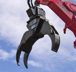
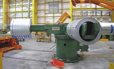
64 Section 4 Bearing Tables & Ratings

65 MT Series Introduction MT Series turntable bearings have a rectangular cross-section and range in size from 4 47 inches OD ( mm). They provide optimal economy and capacity for a given envelope dimension. Design Features The internal configuration consists of deep groove gothic arch raceways and maximum ball complement. This results in a four-point contact design which provides exceptional moment, thrust, and radial load capacities. Integral face riding seals for the larger sizes and non-contact shields for the smaller assist in the exclusion of contaminants. These features make them an ideal choice for a wide range of applications from light to heavy duty. MT Series bearings are offered in nongeared (MTO) and externally geared (MTE) configurations. The gears are Fellows Stub Involute up to the MTE-324 size and Stub Involute for larger sizes, all manufactured to AGMA Class Q6 quality. Contact Kaydon for tooth backlash allowance. Part numbers ending in a T suffix have threaded mounting holes. Thread depths are a minimum of 1.5 times the nominal hole size diameter indicated. Part numbers ending in an "X" suffix provide additional load capacity. Availability MT Series bearings are available from stock, and mating pinions for the geared versions through MTE-705 are also available. Refer to page 70 for mating pinions. Applications MT Series bearings have been used successfully in a wide range of applications from light to heavy duty. The smaller sizes are well suited for: Manipulators Jib cranes Lift-assist devices Work positioners Larger sizes are well suited for: Truck-mounted cranes Aerial lifts Hoists Small wind turbines Non-precision positioning tables Section 4 Bearing Tables & Ratings Versions of these standard bearings with features manufactured to higher precision requirements can be used in machine tool, material handling, power transmission, radar, and robotics applications. Contact Kaydon to speak with an applications engineer about the following options: Precision runout control Precision gear Preload for zero free play and increased stiffness Pilot diameters Tapped mounting holes ENDURAKOTE plating for increased corrosion resistance Kaydon also offers a high-precision KH Series in a standard line which incorporates all the above except ENDURAKOTE plating
66 MT Series MTO-050 & MTO-065 only NO GEAR OUTLINE DIMENSIONS AND WEIGHT Section 4 Bearing Tables & Ratings KAYDON P/N D o (in) d i (in) MTO MTO-050T MTO MTO-065T H (in) H i /H o (in) G APPROX. (lbs) MTO MTO-122T MTO MTO-143T MTO MTO-145T MTO-145X MTO MTO-170T MTO MTO-210T MTO-210X MTO MTO-265T MTO-265X *MTO-324T MTO-324X * Part number MTO-324 has been superseded by MTO-324T
67 MT Series L o (in) OUTER RING n o B o (in) MOUNTING HOLES L i (in) INNER RING MOMENT RATING C rm (ft-lbs) M M , M M8 1, , M M8 5, , M M10 8, , / / , , , M M12 16, , / / , , , / / , , / / , ,400 n i B i (in) Section 4 Bearing Tables & Ratings
68 MT Series EXTERNAL GEAR Section 4 Bearing Tables & Ratings KAYDON P/N OUTLINE DIMENSIONS AND WEIGHT OUTER RING MOUNTING HOLES INNER RING D o d i H H i /H G o L o n o B o L i n i B i APPROX. (in) (in) (in) (in) (lbs) (in) (in) (in) (in) MTE MTE-145T / /8-11 MTE-145X MTE MTE-210T / /8-11 MTE-210X MTE MTE-265T / /8-11 MTE-265X *MTE-324T / /8-11 MTE-324X MTE MTE-415T / /4-10 MTE MTE-470T / /4-10 MTE MTE-540T / /4-10 MTE MTE-590T / /8-9 MTE MTE-705T / /8-9 MTE MTE-730T MTE MTE-870T / /8-7 * Part number MTE-324 has been superseded by MTE-324T
69 MT Series TOOTH FORM GEAR DATA a = 20 D 2 P d z 2 b 2 F z (lbs) MAX GEAR TOOTH LOAD MOMENT RATING C rm (in) (in) (ft-lbs) FS / ,140 26,000 FS / ,140 26,000 FS / ,140 30,600 FS / ,810 44,500 FS / ,810 44,500 FS / ,290 52,100 FS / ,330 62,000 FS / ,330 62,000 FS / ,330 71,900 FS / , ,400 FS / , ,400 SD , ,200 SD , ,200 SD , ,600 SD , ,600 SD , ,000 SD , ,000 SD , ,700 SD , ,700 SD , ,200 SD , ,200 SD , ,000 SD , ,000 SD , ,800 SD , ,800 Section 4 Bearing Tables & Ratings
70 MT Series Load Charts Thrust (lbs x 1,000) (A) MT-050 (B) MT-065 (C) MT-122 (D) MT A B C D Moment (ft-lbs x 1,000) Section 4 Bearing Tables & Ratings Thrust (lbs x 1,000) E F G H I J K Moment (ft-lbs x 1,000) (E) MT-170 (F) MT-145 (G) MT-145X (H) MT-210 (I) MT-210X (J) MT-265 (K) MT-265X Rating Charts are only applicable for operating conditions defined as NORMAL OPERATION in Section 2 and when installed and maintained as defined in Section 3 of this catalog. Bearing diameter increase does not necessarily ensure bearing rating increase due to variations in rolling elements, ring section, and fastener complements. For information concerning the basis for development of Rating Charts refer to the LOAD RATING paragraph in Section
71 MT Series Load Charts Thrust (lbs x 1,000) (L) MT-324 (M) MT-324X (N) MT-415 (O) MT-470 (P) MT L M Moment (ft-lbs x 1,000) N O P Thrust (lbs x 1,000) 1,400 1,200 1, Q R S T ,000 Moment (ft-lbs x 1,000) (Q) MT-590 (R) MT-705 (S) MT-730 (T) MT-870 Section 4 Bearing Tables & Ratings Rating Charts are only applicable for operating conditions defined as NORMAL OPERATION in Section 2 and when installed and maintained as defined in Section 3 of this catalog. Bearing diameter increase does not necessarily ensure bearing rating increase due to variations in rolling elements, ring section, and fastener complements. For information concerning the basis for development of Rating Charts refer to the LOAD RATING paragraph in Section
72 Pinion Tables for RK, HS and MT Series Mating Pinions for RK Series Bearings Section 4 Bearing Tables & Ratings BEARING P/N RK6-16 thru RK6-29 RK6-33 thru RK6-43 PINION P/N TOOTH FORM SD SD GEAR DATA (a = 20 ) OUTLINE DIMENSIONS AND WEIGHT z 1 P d b 1 L 1 D 1 D o1 D r1 D i1 w G APPROX. (in) (in) (in) (in) (in) (in) (in) (in) (lbs) Tolerances Ref. ±.015 ±.015 Ref. Mating Pinions for HS Series Bearings BEARING P/N HS6-16 thru HS6-29 HS6-33 thru HS6-43 PINION P/N TOOTH FORM SD SD GEAR DATA (a = 20 ) Ref OUTLINE DIMENSIONS AND WEIGHT 1/4 5/ z 1 P d b 1 L 1 D 1 D o1 D r1 D i1 w G APPROX. (in) (in) (in) (in) (in) (in) (in) (in) (lbs) Tolerances Ref. ±.015 ±.015 Ref Ref /4 5/ Mating Pinions for MT Series Bearings BEARING P/N MTE-145 thru MTE-324 MTE-415 thru MTE-540 MTE-590 thru MTE-705 PINION P/N TOOTH FORM GEAR DATA (a = 20 ) OUTLINE DIMENSIONS AND WEIGHT z 1 P d b 1 L 1 D 1 D o1 D r1 D i1 w G APPROX. (in) (in) (in) (in) (in) (in) (in) (in) (lbs) FS 17 5/ / SD SD Tolerances Ref. ±.015 ±.015 Ref Ref /4 5/

73 KH Series Introduction KH Series turntable bearings have a rectangular cross-section and range in size from inches OD ( mm). They provide precise positioning and repeatability in applications where rotation is constant, intermittent, or oscillating. Design Features The internal configuration is a deepgroove gothic arch raceway, which provides four points of contact with the balls, enabling it to carry radial, thrust, and moment loads individually or simultaneously. The use of internal diametral preload provides for greater stiffness, which combined with tightly controlled radial and axial runouts, delivers accurate repeatability. The axial runouts are.001 TIR and the radial runouts for locating diameters are.002 TIR. A separator is used to maintain consistent ball spacing interval, keep friction to a minimum, and minimize noise. Integral face riding seals are provided to assist in the exclusion of contaminants. KH Series bearings are offered in nongeared and externally geared configurations. The gears have Full Depth Involute teeth and are manufactured to an AGMA Class Q8 quality, allowing for decreased backlash, more accurate positioning, and less noise while operating. Availability KH Series bearings are available from stock. Applications KH Series bearings have been used successfully in applications demanding higher precision, including: Precision rotary index tables Radar antennas Satellite antennas Robots Medical equipment Machine tool tables Any design where the KH bearing features will interface with other precision components. Section 4 Bearing Tables & Ratings
74 KH Series NO GEAR KAYDON P/N HOLE DATA GEAR OUTLINE DIMENSIONS AND WEIGHT GEAR DATA TOOTH OUTER RING INNER RING RATING D o d i D i d o G L o n o L i n i D 2 b 2 Z 2 F z APPROX. (in) (in) (in) (in) (lbs) (in) (in) (in) (in) (lbs) KH-125P KH-166P KH-225P KH-275P KH-325P TOLERANCES ±.050 ± /-0 +0/ EXTERNAL GEAR Section 4 Bearing Tables & Ratings KAYDON P/N Size OUTLINE DIMENSIONS AND WEIGHT Axial (lbs) Dynamic Moment (ft-lbs) Axial (lbs) Intermittent Moment (ft-lbs) KH ,000 13,100 60,000 25,800 KH ,000 20,500 82,800 45,200 KH ,000 30, ,200 56,000 KH ,000 39, ,000 75,000 KH ,000 48, ,000 92,000 OUTER RING HOLE DATA INNER RING GEAR DATA - FD INVOLUTE P d = 6, a = 20, AGMA Q8 GEAR TOOTH RATING F z D o d i D i d o G L o n o L i n i D 2 b 2 Z 2 APPROX. (in) (in) (in) (in) (lbs) (in) (in) (in) (in) (lbs) KH-125E ,480 KH-166E ,570 KH-225E ,670 KH-275E ,700 KH-325E ,730 TOLERANCES +0/-.020 ± /-0 +0/ ±.030 DYNAMIC and INTERMITTENT CAPACITIES Note: Dynamic-L10 capabilities based on million revolutions. Values do not apply simultaneously. Intermittent-Individual capacity limits for maximum loading when normal mode of operation is an intermittent load application and rotation
75 KH Series Non-geared Section 4 Bearing Tables & Ratings External geared
76 KH Series Deflection Chart KH Series Radial Deflection Radial Deflection (in) A B C D E (A) KH-125 (B) KH-166 (C) KH-225 (D) KH-275 (E) KH Radial Load (lbs x 1,000) Section 4 Bearing Tables & Ratings Axial Deflection (in) Tilt of Axis (radians) KH Series Axial Deflection A A B B C D E Axial Load (lbs x 1,000) C KH Series Tilt of Axis D E (A) KH-125 (B) KH-166 (C) KH-225 (D) KH-275 (E) KH-325 (A) KH-125 (B) KH-166 (C) KH-225 (D) KH-275 (E) KH-325 Moment Load (ft-lbs x 1,000)

77 XT Series Introduction XT Series turntable bearings are custom designs having a rectangular crosssection, and are available in sizes up to 218 inches OD (5500 mm). They are well suited for a wide range of applications where our standard product series do not meet your size, capacity, or weight requirements. Design Features The internal configuration consists of deep groove gothic arch raceways and maximum ball complement. This results in a four-point contact design which provides exceptional moment, thrust, and radial load capacities. Integral seals are provided to assist in the exclusion of contaminants. XT Series bearings are available in internal geared, external geared, and non-geared configurations. Availability XT Series bearings are made to order, and can be customized for the specific application. Applications XT Series bearings have been used successfully in a wide range of applications, including: Cranes Aerial lifts Excavators Wind turbines Utility derricks Log loaders and fellers Feller heads Section 4 Bearing Tables & Ratings
78 XT Series Section 4 Bearing Tables & Ratings NO GEAR KAYDON P/N OUTLINE DIMENSIONS AND WEIGHT D o d i H H o H i D r * d r * G APPROX. (in) (in) (in) (in) (in) (in) (in) (lbs) , , ,350 *No internal or external diameters for this type
79 XT Series HOLE DATA GEAR DATA GEAR BEARING TOOTH MOMENT OUTER RING INNER RING a = 20 RATING RATING L F z C o n o B o L i n i B i rm TOOTH D 2 P d z 2 x 2 b 2 or (m) (in) (in) (in) (in) FORM (in) (in) (lbs) (ft-lbs) , , , , ,000 Section 4 Bearing Tables & Ratings , , , ,675, ,337, ,258,
80 XT Series Section 4 Bearing Tables & Ratings INTERNAL GEAR KAYDON P/N OUTLINE DIMENSIONS AND WEIGHT D o d i H H o H i D r * d r G APPROX. (in) (in) (in) (in) (in) (in) (in) (lbs) , , , , , , , ,500 *No external diameters for this type
81 XT Series HOLE DATA GEAR DATA GEAR BEARING TOOTH MOMENT OUTER RING INNER RING a = 20 RATING RATING L F z C o n o B o L i n i B i rm TOOTH D 2 P d z 2 x 2 b 2 or (m) (in) (in) (in) (in) FORM (in) (in) (lbs) (ft-lbs) FS / ,800 71, FS / ,800 81, SD , , SD , , SD , ,000 Section 4 Bearing Tables & Ratings SD , , FD , , SD ,900 1,131, SD ,500 1,650, FD ,600 1,831, SD ,450 3,764, FD ,500 3,457, SD ,900 6,125, FD (10) ,300 1,013, SD ,400 3,003,
82 XT Series Section 4 Bearing Tables & Ratings EXTERNAL GEAR Kaydon P/N OUTLINE DIMENSIONS AND WEIGHT D o d i H H o H i D r d r * G APPROX. (in) (in) (in) (in) (in) (in) (in) (lbs) , , , , , , , , ,700 *No internal diameters for this type
83 XT Series HOLE DATA GEAR DATA GEAR BEARING TOOTH MOMENT OUTER RING INNER RING a = 20 RATING RATING L F z C o n o B o L i n i B i rm TOOTH D 2 P d z 2 x 2 b 2 or (m) (in) (in) (in) (in) FORM (in) (in) (lbs) (ft-lbs) FD ,470 6, FS / , , SD , , SD , , SD , ,000 Section 4 Bearing Tables & Ratings SD , , SD ,300 1,220, SD ,850 1,522, FD ,600 2,873, SD ,900 3,575, SD ,600 4,951, FD (18) ,800 2,070, FD (20) ,500 4,176, FD (20) ,000 5,210, FD (12) ,100 3,190,
84 XT Series Load Charts - No Gear Section 4 Bearing Tables & Ratings Thrust (lbs x 1,000) Thrust (lbs x 1,000) ,500 2,250 2,000 1,750 1,500 1,250 1, A B C D E F Moment (ft-lbs x 1,000) (A) (B) (C) (D) (E) (F) (G) (H) (I) (J) (K) ,000 1,500 2,000 2,500 3,000 3,500 4, G H I J K Moment (ft-lbs x 1,000) Rating Charts are only applicable for operating conditions defined as NORMAL OPERATION in Section 2 and when installed and maintained as defined in Section 3 of this catalog. Bearing diameter increase does not necessarily ensure bearing rating increase due to variations in rolling elements, ring section, and fastener complements. For information concerning the basis for development of Rating Charts refer to the LOAD RATING paragraph in Section 2.
85 XT Series Load Charts - Internal Gear Thrust (lbs x 1,000) L M N O P Q Moment (ft-lbs x 1,000) (L) (M) (N) (O) (P) (Q) Thrust (lbs x 1,000) Thrust (lbs x 1,000) 1,600 1,400 1,200 1, ,500 3,000 2,500 2,000 1,500 1,000 R S T U V ,000 1,200 1,400 1,600 1,800 2,000 Moment (ft-lbs x 1,000) (R) (S) (T) (U) (V) (W) (X) (Y) (Z) Section 4 Bearing Tables & Ratings W X Y Z 0 1,000 2,000 3,000 4,000 5,000 Moment (ft-lbs x 1,000) 6,000 7,000 Rating Charts are only applicable for operating conditions defined as NORMAL OPERATION in Section 2 and when installed and maintained as defined in Section 3 of this catalog. Bearing diameter increase does not necessarily ensure bearing rating increase due to variations in rolling elements, ring section, and fastener complements. For information concerning the basis for development of Rating Charts refer to the LOAD RATING paragraph in Section
86 XT Series Load Charts - External Gear Section 4 Bearing Tables & Ratings Thrust (lbs x 1,000) Thrust (lbs x 1,000) Thrust (lbs x 1,000) 1,100 1, ,500 2,000 1,500 1, ,000 2,500 2,000 1,500 1,000 AB AC AD AE Moment (ft-lbs x 1,000) 0 AA AF AG AH AI AJ ,000 1,500 2,000 2,500 3,000 Moment (ft-lbs x 1,000) (AA) (AB) (AC) (AD) (AE) (AF) (AG) (AH) (AI) (AJ) (AK) (AL) (AM) (AN) (AO) AK AL AM AN AO 0 1,000 2,000 3,000 4,000 5,000 6,000 Moment (ft-lbs x 1,000) Rating Charts are only applicable for operating conditions defined as NORMAL OPERATION in Section 2 and when installed and maintained as defined in Section 3 of this catalog. Bearing diameter increase does not necessarily ensure bearing rating increase due to variations in rolling elements, ring section, and fastener complements. For information concerning the basis for development of Rating Charts refer to the LOAD RATING paragraph in Section

87 DT Series Bearings Introduction The DT Series consists of the eightpoint ball bearing Kaydon originally developed to provide maximum load capacity for given envelope and bolt circle diameters. It provides up to 80% increase in capacity over that of a single row four-point design, yet has a smaller profile than a three-row roller design. Design Features The internal configuration consists of two deep groove gothic arch raceways, each with a maximum ball complement, located in both the inner and outer rings. This results in a total of eight surfaces where the balls may contact at any time, providing exceptional moment, thrust, and radial load capacities. Through precise manufacturing, the raceways are closely matched to provide a high degree of load sharing. Integral seals are provided to assist in the exclusion of contaminants. Availability DT Series bearings are made to order with a fully customizable hole pattern for bearing retention, and an internal or external gear or other drive mechanism. Applications DT Series bearings have been used successfully in heavy duty applications including: Large excavators Large cranes Mining equipment Wind turbines Telescopes Section 4 Bearing Tables & Ratings
88 DT Series Section 4 Bearing Tables & Ratings NO GEAR KAYDON P/N OUTLINE DIMENSIONS AND WEIGHT D o d i H H o H i D r * d r * G Approx. (in) (in) (in) (in) (in) (in) (in) (lbs) , , , , ,950 *No internal or external diameters for this type
89 DT Series HOLE DATA GEAR DATA GEAR BEARING TOOTH MOMENT OUTER RING INNER RING a = 20 RATING RATING L F z C o n o B o L i n i B i rm TOOTH D 2 P d z 2 x 2 b 2 or (m) (in) (in) (in) (in) FORM (in) (in) (lbs) (ft-lbs) Section 4 Bearing Tables & Ratings , , , /4-7 2,083, ,934, ,666, ,098,
90 DT Series Section 4 Bearing Tables & Ratings INTERNAL GEAR KAYDON P/N OUTLINE DIMENSIONS AND WEIGHT D o d i H H o H i D r * d r G Approx. (in) (in) (in) (in) (in) (in) (in) (lbs) , , , , , , , ,850 *No external diameters for this type
91 DT Series HOLE DATA GEAR DATA GEAR BEARING TOOTH MOMENT OUTER RING INNER RING a = 20 RATING RATING L F z C o n o B o L i n i B i rm TOOTH D 2 P d z 2 x 2 b 2 or (m) (in) (in) (in) (in) FORM (in) (in) (lbs) (ft-lbs) Section 4 Bearing Tables & Ratings FD (14) ,640 1,225, SD ,680 3,921, / SD ,400 4,863, FD (12) ,140 2,534, FD (12) ,770 3,896, FD (18) ,870 9,075, FD ,940 8,751, FD (18) ,340 12,625,
92 DT Series Section 4 Bearing Tables & Ratings EXTERNAL GEAR KAYDON P/N OUTLINE DIMENSIONS AND WEIGHT D o d i H H o H i D r d r * G Approx. (in) (in) (in) (in) (in) (in) (in) (lbs) , , , , , , , , ,100 *No internal diameters for this type
93 DT Series HOLE DATA GEAR DATA GEAR BEARING TOOTH MOMENT OUTER RING INNER RING a = 20 RATING RATING L F z C o n o B o L i n i B i rm TOOTH D 2 P d z 2 x 2 b 2 or (m) (in) (in) (in) (in) FORM (in) (in) (lbs) (ft-lbs) FS / ,850 65,200 Section 4 Bearing Tables & Ratings M24x FD (8) , , SD ,480 2,132, FD ,480 3,470, FD (10) ,400 3,335, FD (14) ,760 4,793, SD ,490 8,669, FD (20) ,060 3,658, FD ,780 14,639, SD ,120 18,293, FD ,080 18,000,
94 DT Series Load Charts No Gear (A) (B) (C) Thrust (lbs x 1,000,000) Section 4 Bearing Tables & Ratings Thrust (lbs x 1,000,000) A B C Moment (ft-lbs x 1,000,000) (D) (E) (F) (G) D E F G Moment (ft-lbs x 1,000,000) Rating Charts are only applicable for operating conditions defined as NORMAL OPERATION in Section 2 and when installed and maintained as defined in Section 3 of this catalog. Bearing diameter increase does not necessarily ensure bearing rating increase due to variations in rolling elements, ring section, and fastener complements. For information concerning the basis for development of Rating Charts refer to the LOAD RATING paragraph in Section
95 DT Series Load Charts Internal Gear Thrust (lbs x 1,000,000) (H) (I) (J) (K) Thrust (lbs x 1,000,000) H I J K Moment (ft-lbs x 1,000,000) (L) (M) (N) (O) Section 4 Bearing Tables & Ratings L M N O Moment (ft-lbs x 1,000,000) Rating Charts are only applicable for operating conditions defined as NORMAL OPERATION in Section 2 and when installed and maintained as defined in Section 3 of this catalog. Bearing diameter increase does not necessarily ensure bearing rating increase due to variations in rolling elements, ring section, and fastener complements. For information concerning the basis for development of Rating Charts refer to the LOAD RATING paragraph in Section
96 DT Series Load Charts External Gear Thrust (lbs x 1,000,000) P (P) (Q) (R) (S) (T) Section 4 Bearing Table & Ratings Thrust (lbs x 1,000,000) Q R S T Moment (ft-lbs x 1,000,000) (U) (V) (W) (X) (Y) (Z) U V W X Y Z Moment (ft-lbs x 1,000,000) Rating Charts are only applicable for operating conditions defined as NORMAL OPERATION in Section 2 and when installed and maintained as defined in Section 3 of this catalog. Bearing diameter increase does not necessarily ensure bearing rating increase due to variations in rolling elements, ring section, and fastener complements. For information concerning the basis for development of Rating Charts refer to the LOAD RATING paragraph in Section

97 XR Series Introduction The XR Series consists of KAYDON cross roller bearings. They provide a high degree of stiffness and low rotational torque within a minimal envelope. This design should be considered when a four-point contact ball bearing does not meet the operating performance requirements for torque and stiffness. Design Features The internal configuration consists of cylindrical rollers in a v-shaped groove in each ring. The rollers are oriented with alternating axes of rotation. Positioned in this manner, the bearing accepts all combinations of radial, thrust, and moment loads. Rotational torque is less than a four-point contact ball design because each roller only transmits load in a single direction, and the greater contact area and geometry of a roller versus a ball provides a higher degree of stiffness and rigidity. A roller of approximately the same size as a ball has greater load-carrying ability. However, because not all the rollers are oriented in one direction, their thrust and moment load capacity is less than that of a four-point ball bearing. Gear teeth or other drive mechanisms can be provided on the inner or outer support ring, and your choice of hole pattern can be added for bearing retention. Availability XR Series bearings are custom manufactured to fit the design and specification. Applications XR Series bearings have been used successfully in applications requiring extra stiffness with a low torque requirement including: Radar Military turrets Machine tools Excavators Section 4 Bearing Table & Ratings
98 XR Series Section 4 Bearing Table & Ratings NO GEAR KAYDON P/N OUTLINE DIMENSIONS AND WEIGHT OUTER RING HOLE DATA INNER RING D o d i H H o H i D r d r G L o n o B o L i n i B i APPROX. (in) (in) (in) (in) (in) (in) (in) (lbs) (in) (in) (in) (in) M16x M16x / / , , , M36x , Note: Capacities are dynamic and based on an L10 life of 1 million revolutions per ABMA Std Values listed do not apply simultaneously. Ring cross section and bolted joint configuration used may result in lower bearing capacity ratings
99 XR Series TOOTH FORM GEAR DATA DYNAMIC CAPACITIES a = 20 GEAR TOOTH RATING 1 MILLION REVOLUTIONS L10 LIFE D 2 P d z 2 x 2 b 2 F z RADIAL THRUST MOMENT or (m) (in) (in) (lbs) (lbs) (lbs) (ft-lbs) 19,150 22,340 7,530 36,850 42,830 20,140 64,560 73,730 65,660 81,310 91, ,170 Section 4 Bearing Table & Ratings 235, , , , , , , , , , ,250 1,450, , ,130 4,185, , ,130 4,879,
100 XR Series Section 4 Bearing Table & Ratings INTERNAL GEAR KAYDON P/N OUTLINE DIMENSIONS AND WEIGHT OUTER RING HOLE DATA INNER RING D o d i H H o H i D r d r G L o n o B o L i n i B i APPROX. (in) (in) (in) (in) (in) (in) (in) (lbs) (in) (in) (in) (in) / / / / M20x M20x / , , , , Note: Capacities are dynamic and based on an L10 life of 1 million revolutions per ABMA Std Values listed do not apply simultaneously. Ring cross section and bolted joint configuration used may result in lower bearing capacity ratings
101 XR Series TOOTH FORM GEAR DATA DYNAMIC CAPACITIES a = 20 GEAR TOOTH RATING 1 MILLION REVOLUTIONS L10 LIFE D 2 P d z 2 x 2 b 2 F z RADIAL THRUST MOMENT or (m) (in) (in) (lbs) (lbs) (lbs) (ft-lbs) FD ,345 64,620 73,810 65,430 SD , , , ,180 FD , , , ,220 FD (10) , , , ,160 Section 4 Bearing Table & Ratings FD , , , ,450 FD (12) , , ,660 1,315,740 FD , , ,230 2,389,570 FD (24) , , ,030 3,797,780 SD , , ,460 4,057,
102 XR Series Section 4 Bearing Table & Ratings EXTERNAL GEAR KAYDON P/N OUTLINE DIMENSIONS AND WEIGHT OUTER RING HOLE DATA INNER RING D o d i H H o H i D r d r G L o n o B o L i n i B i APPROX. (in) (in) (in) (in) (in) (in) (in) (lbs) (in) (in) (in) (in) M12x , , , , , Note: Capacities are dynamic and based on an L10 life of 1 million revolutions per ABMA Std Values listed do not apply simultaneously. Ring cross section and bolted joint configuration used may result in lower bearing capacity ratings
103 XR Series TOOTH FORM GEAR DATA DYNAMIC CAPACITIES a = 20 GEAR TOOTH RATING 1 MILLION REVOLUTIONS L10 LIFE D 2 P d z 2 x 2 b 2 F z RADIAL THRUST MOMENT or (m) (in) (in) (lbs) (lbs) (lbs) (ft-lbs) FD ,320 24,130 27,780 13,190 FD ,430 85,170 99,260 69,470 FD (5) ,725 64,560 73,730 65,660 FD (8) ,130 58,790 66,360 77,600 Section 4 Bearing Table & Ratings FD , , , ,290 FD (10) , , , ,060 SD , , , ,330 FD (10) , , , ,070 FD (14) , , , ,340 SD , , , ,710 FD , , ,960 1,557,670 FD (16) , , ,320 4,874,640 FD (18) ,360 1,005,010 1,126,290 8,903,


104 Section 4 Bearing Table & Ratings

105 TR Series The TR Series consists of three-row roller bearings which offer the highest capacity for a given diameter. When an XR or DT Series bearing doesn t meet the stiffness and capacity requirements, consider the TR Series. Design Features The bearing has three independent rows of rollers oriented normal to the direction of loads being transmitted through the bearing. Their orientation is selected to optimize capacity, provide low frictional resistance and minimize deflection. The top and bottom rows of rollers transmit any opposing thrust loads and combine to transmit any moment loading, while the middle row transmits any radial loads. The rollers, the separator configuration used for each and the mating raceways are sized to meet load or other application requirements. In order to obtain these performance benefits, the supporting structures must satisfy higher stiffness and lower flatness requirements than those for similar sized XT or DT Series bearings. Gear teeth or other drive mechanisms can be provided on the inner or outer support ring, and the choice of hole pattern can be added for bearing retention. Availability TR Series bearings are custom manufactured to fit the design and specification. Applications TR Series bearings have been used successfully in heavy duty applications requiring extra stiffness and capacity including: Radar Cranes Excavators Stackers and reclaimers Heavy mill equipment Section 4 Bearing Table & Ratings
106 TR Series Section 4 Bearing Table & Ratings NO GEAR KAYDON P/N OUTLINE DIMENSIONS AND WEIGHT D o d i H H o H i D r D i d o d r G Approx. (in) (in) (in) (in) (in) (in) (in) (in) (in) (lbs) , , , , , , , , ,
107 TR Series HOLE DATA GEAR DATA GEAR BEARING TOOTH MOMENT OUTER RING INNER RING a = 20 RATING RATING L F z C o n o B o L i n i B i rm TOOTH D 2 P d z 2 x 2 b 2 or (m) (in) (in) (in) (in) FORM (in) (in) (lbs) (ft-lbs) /4-7 1,104, ,275,900 Section 4 Bearing Table & Ratings ,332, ,404, ,936, ,653, ,124, ,339, ,976,
108 TR Series Section 4 Bearing Table & Ratings INTERNAL GEAR KAYDON P/N OUTLINE DIMENSIONS AND WEIGHT D o d i H H o H i D r * D i d o d r G Approx. (in) (in) (in) (in) (in) (in) (in) (in) (in) (lbs) , , , , , , , , ,950 *No external diameters for this type
109 TR Series HOLE DATA GEAR DATA GEAR BEARING TOOTH MOMENT OUTER RING INNER RING a = 20 RATING RATING L F z C o n o B o L i n i B i rm TOOTH D 2 P d z 2 x 2 b 2 or (m) (in) (in) (in) (in) FORM (in) (in) (lbs) (ft-lbs) SD , ,700 Section 4 Bearing Table & Ratings FD (10) ,480 1,479, / SD ,440 3,514, FD (16) ,240 4,250, FD (14) ,210 9,038, FD (22) ,850 10,642, /2-6 FD ,140 9,275, FD (12) ,840 18,616, FD (20) ,000 28,772, FD ,700 43,823,
110 TR Series Section 4 Bearing Table & Ratings EXTERNAL GEAR KAYDON P/N OUTLINE DIMENSIONS AND WEIGHT D o d i H H o H i D r D i d o d r G Approx. (in) (in) (in) (in) (in) (in) (in) (in) (in) (lbs) , , , , , , , ,
111 TR Series HOLE DATA GEAR DATA GEAR BEARING TOOTH MOMENT OUTER RING INNER RING a = 20 RATING RATING L F z C o n o B o L i n i B i rm TOOTH D 2 P d z 2 x 2 b 2 or (m) (in) (in) (in) (in) FORM (in) (in) (lbs) (ft-lbs) Section 4 Bearing Table & Ratings FD , , FD (12) ,510 1,329, FD (18) ,630 4,129, / /2-6 SD ,510 12,091, FD (20) ,500 11,652, FD (20) ,600 24,086, FD (18) ,770 32,339, FD ,300 43,823,
112 TR Series Load Charts No Gear Section 4 Bearing Table & Ratings Thrust (lbs x 1,000,000) Thrust (lbs x 1,000,000) A B C D E Moment (ft-lbs x 1,000,000) F G H I Moment (ft-lbs x 1,000,000) (A) (B) (C) (D) (E) (F) (G) (H) (I) Rating Charts are only applicable for operating conditions defined as NORMAL OPERATION in Section 2 and when installed and maintained as defined in Section 3 of this catalog. Bearing diameter increase does not necessarily ensure bearing rating increase due to variations in rolling elements, ring section, and fastener complements. For information concerning the basis for development of Rating Charts refer to the LOAD RATING paragraph in Section
113 TR Series Load Charts Internal Gear Thrust (lbs x 1,000,000) Thrust (lbs x 1,000,000) J K L M N Moment (ft-lbs x 1,000,000) O P Q R S Moment (ft-lbs x 1,000,000) (J) (K) (L) (M) (N) (O) (P) (Q) (R) (S) Section 4 Bearing Table & Ratings Rating Charts are only applicable for operating conditions defined as NORMAL OPERATION in Section 2 and when installed and maintained as defined in Section 3 of this catalog. Bearing diameter increase does not necessarily ensure bearing rating increase due to variations in rolling elements, ring section, and fastener complements. For information concerning the basis for development of Rating Charts refer to the LOAD RATING paragraph in Section
114 TR Series Load Charts External Gear Section 4 Bearing Table & Ratings Thrust (lbs x 1,000,000) Thrust (lbs x 1,000,000) T U V W Moment (ft-lbs x 1,000,000) X Y Z AA Moment (ft-lbs x 1,000,000) (T) (U) (V) (W) (X) (Y) (Z) (AA) Rating Charts are only applicable for operating conditions defined as NORMAL OPERATION in Section 2 and when installed and maintained as defined in Section 3 of this catalog. Bearing diameter increase does not necessarily ensure bearing rating increase due to variations in rolling elements, ring section, and fastener complements. For information concerning the basis for development of Rating Charts refer to the LOAD RATING paragraph in Section


115 Section 4 Bearing Table & Ratings
116 Section 5 Contents Specialty Products & Services WireX Wire-Race Bearings... pg. 115 Custom Bearings... pgs Remanufacturing Program... pgs Endurakote Plating...pgs Section 5 Specialty Products & Services

117 Custom WireX Wire-Race Bearings Kaydon WireX bearings were originally designed for military turret applications, where space and weight are at a premium and corrosion resistance is essential. They consist of wire raceways inserted in lightweight support rings, allowing for a high load capacity and large diameter in a bearing that can be 60% lighter than one made entirely of steel. Design Features The bearing s support rings are typically aluminum, with contoured grooves for supporting, positioning, and alignment of steel wire raceways. The rolling elements are typically stainless steel, with up to three rows of rollers to fit individual requirements. This internal configuration allows WireX bearings to be more tolerant of non-rigid and out-of-flat mounting structures. Irregularities can be accommodated by the relative movement of the wire inserts in their supporting grooves. Gear teeth or other drive mechanisms can be provided on the inner or outer support ring, and a variety of hole patterns can be added for bearing retention. WireX bearings can often be rebuilt a substantial savings when compared to complete bearing replacement. Availability WireX bearings are custom manufactured to fit your design and specification. Applications WireX bearings have been used successfully in applications requiring a lightweight, corrosion-resistant bearing including: Turrets Radar Sonar Section 5 Specialty Products & Services


118 Custom Bearing Capabilities In addition to the more standard bearings shown on earlier pages, KAYDON has extensive experience in the design and manufacture of customized or special bearings and assemblies. This experience allows us to match the product to the requirements. The ball and roller bearings shown below are only a sampling of our custom capabilities, provided to further inspire your creativity to find the optimum solution. Section 5 Specialty Products & Services Figure 5-1 A thin-sectioned cross roller bearing combines the features of higher stiffness, increased dynamic capacity, and lower turning torque with weight and space savings. Rollers may be oriented as needed to maximum load carrying ability and fatigue life. Designs with similar configurations and features range from 15 inches to over 90 inches. Figure 5-2 A thin-sectioned large diameter bearing with external gear made from special stainless steel rings, plastic rolling elements, and separator for low permeability and to limit out-gassing. Use of plastic rolling elements also permits operation without lubrication. Similar designs and components have been produced for sizes up to 70 inches. Figure 5-3 A complex three-row roller bearing with minimal raceway material provides the customer with light weight and space saving opportunities. The thin sections and unusual configurations permit compact overall design. Three separate rows of rollers permit use in applications with simultaneous as well as reversing radial, axial, and moment loads. Roller complement and raceways may be oriented and designed to optimize capacity and fatigue life as well as stiffness. Designs with similar features have exceeded 90. Figure 5-4 A three ring, two-rolling complement bearing with two integral gears, one on the inner and one on the outer ring is shown. This configuration when combined with precision components permits accurate, smooth, independent, and synchronized rotation of the rings and any attached components. Use of a separator increases the bearing s operating speed capability and, combined with low friction seals, permits minimal rotational resistance. The total package significantly reduces the number of components needed to perform the same functions as this design currently does

119 Custom Bearing Capabilities (continued) Figure 5-5 This flange mounted, thin-sectioned large diameter bearing is light weight, requires minimal space, and fits around existing components. The flanges are scalloped between holes to provide greater weight reduction. The use of double row angular contact rolling complement with separators provides minimal rotational resistance and can be used for high accelerating conditions as well as very high continuous operating speeds. The high precision gear on the inner ring provides for accurate positioning. Figure 5-6 A four-point ball bearing with integrated v-belt groove in one ring permits a simple mechanical drive option at low cost with no lubrication and minimal maintenance. Belt drive designs, flat or tooth, are potential alternative solutions depending on application conditions. Use of a separator increases the bearing s operating speed capability and, combined with low friction seals, permits minimal rotational resistance. Section 5 Specialty Products & Services
120 Remanufacturing Program Section 5 Specialty Products & Services Kaydon offers a bearing repair program that is designed to provide the best service options available no matter the brand or size of bearing. Bearings are assessed for remanufacture from 10 inches to 240 inches in outside diameter (OD). In this program optimized solutions are provided through our experienced sales team, international presence, and process capability. The process begins with the service engineering team partnering with the customer's maintenance or service groups to analyze the bearing. Bearing Failure Warning Signs Perhaps the most difficult task is determining if and when a bearing needs to be serviced. This determination requires much more than a quick visual inspection. Below are a few signs to look for when inspecting bearings that may need to be repaired: The bearing is nearing its suggested life expectancy. The bearing has exceeded an operating temperature of 200 F (93 C). The bearing has been exposed to excessive vibration. The bearing experienced a sudden drop or gain in lubrication. The bearing has a missing or torn seal. The bearing exhibits excessive rotational resistance. The structure has excessive movement or rocking during operation. The mating structure and hardware is damaged, e.g. cracked, broken, distorted, or even missing. The bearing exhibits limited rotation, uncharacteristic vibrations, or noise. Paying attention to these details during regular maintenance checks can help you determine whether a bearing needs maintenance before it causes unnecessary downtime and expense. Careful observation is the first step in creating a program that monitors your bearings and surrounding operations. WARNING: Proper maintenance and handling practices are critical. Failure to follow installation, maintenance, and operating instructions can result in equipment failure, creating a risk of bodily injury or death. To provide the correct repair solution to the damaged bearing, the cause and extent of the damage must be understood. Environmental issues, such as ingress of contamination and water into the bearing, are the common causes of premature bearing failure. Following are typical causes of damage found on bearings and precautions that can be taken to prolong life. Improper Handling: Cage deformation and nicks or gouges can result from improper installation, handling or removal. Precautions: Use proper handling practices along with the correct handling, mounting and disassembly tools. Inadequate Lubrication: Scoring of components or severe bearing deformation can result from inadequate or incorrect lubrication. Precautions: Inspect and replace the lubricant at the manufacturer's recommended interval or as needed, whichever occurs first. If necessary, change or improve lubricant. Corrosion and Etching: Exposure to moisture can lead to etching, pitting, then rusting of bearing components. Spalling may result from bearings that operate after such damage. Precautions: Check seals regularly, ensure proper sealing and store bearings properly. Electric Current: Passage of electric current while a bearing is rotating may cause fluting or grooving. Improper electric grounding while a bearing is stationary can create small burns. Precautions: Shunt the current around the bearing with the proper earth connection before welding. Foreign Material: Abrasions, bruising and grooving can result from abrasive particle contamination and debris. Precautions: Remove the debris, change the lubricant, and check/replace the seals
121 Remanufacturing Program Misalignment: Geometric stress concentration and spalling can result from misalignment, deflections or heavy loading. Precautions: Machine the bearing seats and shoulders accurately. Check accuracy of shaft and housing seats, ensure proper shaft/housing alignment and confirm or reduce operating forces. Overloading: Improper use for the intended application can lead to overload conditions accelerating wear. Precautions: Utilize the equipment for the intended application within the load limits defined. Kaydon Service Options The initial analysis covers the cleaning, verification of internal clearances, disassembly, and inspection of the bearing assembly. The engineering team then assesses the damage and provides a quotation based on the most appropriate remanufacturing type to restore the bearing to full operation. The three repair classifications are: Class A Repair To ensure correct geometry and alignment, bearing assemblies require machining of rolling element pathways and the surfaces that interface with the mounting structure for correct installation. Oversize rolling elements are used to restore the desired internal clearance or preload and new spacers and seals are fitted. Class B Repair Bearing assemblies require polishing or other surface alterations to relieve stressed or corroded areas on the raceway or mounting surfaces. The bearing is reassembled with new rolling elements, spacers, and seals as required. Class R Repair Bearing assemblies require a completely new bearing ring to match an existing repairable ring. The existing raceway is machined to give correct geometry and the new ring and raceway are manufactured to match the repaired component. New rolling elements, spacers, and seals complete the refurbishment. Taking the Next Step 1. Contact the Kaydon Regional Sales Manager or Customer Service Representative for a customized solution or visit 2. The Kaydon representative will work to assess the bearing repair needs. 3. Kaydon will physically assess the bearing s condition and provide a quotation. 4. When the repair is authorized, the plant will perform all necessary repairs and return the bearing within the promised lead time. If it is decided not to proceed with the repair, the damaged bearing will be disposed of or returned. Section 5 Specialty Products & Services
122 ENDURAKOTE Plating for Corrosion-Resistant Bearings Section 5 Specialty Products & Services Introduction ENDURAKOTE plating protects bearings from corrosion and provides substantial life improvements in hostile environments. ENDURAKOTE plating is applied over conventional bearing materials and offers the benefit of corrosion resistance normally found only in stainless steel bearings. The coating is applied to each entire bearing race ring, including the paths, thus leaving no area exposed. Other commercial chrome or cadmium coatings normally accepted and used cannot be applied to the path due to the rolling contact stresses. ENDURAKOTE plating is hard chromium, electrodeposited by a proprietary process which achieves a true molecular bond, and will not flake or peel even under the high contact stresses experienced in the bearing paths. Laboratory and field testing results have proven the benefits of this process. Severe salt spray testing has shown that bearings with ENDURAKOTE plating withstand corrosion as well as or better than AISI 440C stainless steel. The hard, dense exterior surface formed by the coating is extremely wear resistant and is excellent in the retention of the lubricant film. Conventional life testing of bearings with ENDURAKOTE plating has shown that no life derating is necessary. In fact, the extremely hard surface of ENDURAKOTE plating protects the bearing from surface generated damage which can promote premature failure. Since the coating is capable of withstanding extremely high temperatures, the bearings are limited by the bearing materials or lubricant used. The coating used for ENDURAKOTE plating can be applied to any type of bearing and to most bearing materials. Its primary advantage is to utilize stock materials with their economies, and convert them to wear- and corrosion-resistant bearings. This is particularly beneficial for larger diameter bearings or where quick delivery is critical. Thus, cost savings can be achieved over more exotic or specialized materials. Also, stock bearings can have ENDURAKOTE plating applied for quick delivery. The net result is that we can offer bearings with the capacity of conventional bearing steels and the corrosion resistance of AISI 440C stainless steel from standard stock components. Application ENDURAKOTE plating provides corrosion resistance and is effective in increasing wear resistance in sliding surface contacts. The micro-surface composition of ENDURAKOTE plating aids in lubricant dispersion, enhancing base metals to the degree of reducing or eliminating galling, seizing, and high friction, over a wide range of installations and environments. Advantages ENDURAKOTE plating effects a buildup of less than.0002 under normal circumstances. Thus, it can often be applied to stock bearing components which have been specially selected. ENDURAKOTE plating is compatible with most ferrous and nonferrous metal, allowing maximum flexibility in selection of base material. ENDURAKOTE plating is normally a final process, and its quality is constant with any given base metal, insuring design reproducibility. Properties and Characteristics A. Hardness ENDURAKOTE plating, as deposited, has an equivalent hardness in excess of 70 Rockwell C. When measured by conventional micro-hardness methods, the host material will modify this measurement to some degree. B. Coefficient of Friction (Note: Measurements made at 72 F, using other materials for comparison.) Material Against Material Static Sliding Steel Steel Steel Brass, Bronze Steel Brass, Bronze ENDURAKOTE plating ENDURAKOTE plating ENDURAKOTE plating ENDURAKOTE plating
123 ENDURAKOTE Plating (continued) C. Adhesion ENDURAKOTE plating will not flake, crack, chip, peel or otherwise separate from the base material under standard bend tests or under conditions where severe heat is induced. The adherence is adequate to withstand the extremely high compressive stresses in the contact areas of ball and roller bearings. D. Effect On Base The purity of the chromium surface will not be less than 99% as deposited. A comprehensive testing program at KAYDON established that bearings with ENDURAKOTE plating exhibited load-carrying capacities and life expectancy equal to or better than uncoated steel bearings. E. Corrosion Resistance ENDURAKOTE plating resists attack by most organic and inorganic compounds with a ph within the range of 4 and 11, except sulfuric and hydrochloric acids. Porosity of the base metal, compound concentration and exposure time to the compound become corrosion factors, but ENDURAKOTE plating greatly enhances the base material. In severe salt spray tests as well as tap water immersion tests, bearing steel with ENDURAKOTE plating proved equal to fully hardened AISI 440C stainless steel in resistance to rusting. In many instances, ENDURAKOTE plating is better for corrosion protection than cadmium plate, zinc plate, phosphates, chromates, black oxide or normal chrome plate. We invite inquiries about and will be pleased to arrange tests to qualify ENDURAKOTE plating for specific environments. F. Heat Resistance Bearings with ENDURAKOTE plating are designed to maintain their operating characteristics over a temperature range from -65 F to 250 F. G. Surface Quality ENDURAKOTE plating conforms to the texture of the existing surface. Ra finish will be improved slightly down to about 8 Ra; below 4 Ra there is little change. ENDURAKOTE plating has a matte or micro-orange peel surface with very good lubricant retention qualities. H. Food Industries ENDURAKOTE plating can be used on food processing equipment. I. Load Capacity ENDURAKOTE plating does not affect the static or dynamic load capacity of the bearing. Bearing Size Capabilities ENDURAKOTE plating can be applied to turntable bearings up to 45 inches. Restrictions KAYDON does not recommend the use of ENDURAKOTE plating in any low torque or torquesensitive applications. Section 5 Specialty Products & Services
124 Section 6 Contents Appendix & Sales Information Specification Data Sheets...pgs Kaydon Website... pg. 127 Kaydon Literature... pg. 128 Warranty & Legal Information...pgs Section 6 Appendix & Sales Information
125 Specification Data Sheet Choose one of 4 easy ways to complete and return MAIL: Kaydon Corporation, PO Box 688, Muskegon, MI ONLINE: FAX: , bearings@kaydon.com 1. Contact Information Name Title Phone Company Address City State Fax Postal Code Country 2. Quotation Data Quotation Quantity Pcs / delivery lot Annual Usage Pcs / year Required Delivery Weeks Target Price Per Unit Proposal Required Date 3. Application Description (please attach additional drawing or sketch) Application (Reference Table 2-4 Service Factors pg. 17) Which of the following applies? Other considerations o New application o Interchange for existing bearing. Include reason(s) for seeking interchange below. Position of rotation axis o Vertical o Horizontal o Inclined/Variable Nominal (relative to vertical) a degrees R a nge ± b degrees Axial load direction o Compression o Tension (Suspended) Ambient temperature Minimum F Normal F Maximum F Seals Required o No o Yes, Against: Specific Lubrication Required o No o Yes, Type: Special environmental considerations? o No o Yes, Describe: Section 6 Appendix & Sales Information
126 Specification Data Sheet continued 4. Bearing Information Outline Dimensions Minimum Preferred Maximum ID in. in. in. OD in. in. in. Width in. in. in. Size Quantity Style Inner Race o Through o Tapped through o Tapped blind o C drilled o C bored Mounting Holes Outer Race (o Same as inner) o Through o Tapped through o Tapped blind o C drilled o C bored Gear Data o None o Internal o External Tooth Form o Full Depth o Stub Dia. Pitch (Mod) Pitch Diameter in. Pressure angle degrees Number of teeth Addendum mod. in. Face width in. Mating Pinion (s) Number used Number of teeth Addendum Mod. in. OD in. Center Distance o Adjustable o Fixed, distance in. 5. Load Parameters Load Case Bearing Loads Speed (RPM) Gear Load Axial (lbs) Radial (lbs) Moment (ft-lbs) Mean Max Torque (ft-lbs) Percent of Time Static Normal Operating 1 Normal Operating 2 Normal Operating 3 Maximum Operating Test/Overload Section 6 Appendix & Sales Information Safety factor included in loads above? Rotation Life required (L10) Shocks or vibrations? Special conditions: materials, torque, accuracy, seals, protective coatings, etc. 6. Comments o No o Yes, o Intermittent o Continuous without interruption o Oscillating, degrees o No o Yes, describe: Additional application service factor required? o One direction only o Alternating directions o No o Yes, o Hours (based on speeds in above table) o Revolutions / oscillations

 Application (Reference Table 2-4 Service Factors pg. 17) Which of the following applies?")
 a degrees R a nge ± b degrees Axial load direction o Compression o Tension (Suspended) Ambient")
127 Specification Data Sheet Choose one of 4 easy ways to complete and return MAIL: Kaydon Corporation, PO Box 688, Muskegon, MI ONLINE: FAX: , bearings@kaydon.com 1. Contact Information Name Title Phone Company Address City State Fax Postal Code Country 2. Quotation Data Quotation Quantity Pcs / delivery lot Annual Usage Pcs / year Required Delivery Weeks Target Price Per Unit Proposal Required Date 3. Application Description (please attach additional drawing or sketch) Application (Reference Table 2-4 Service Factors pg. 17) Which of the following applies? Other considerations o New application o Interchange for existing bearing. Include reason(s) for seeking interchange below. Position of rotation axis o Vertical o Horizontal o Inclined/Variable Nominal (relative to vertical) a degrees R a nge ± b degrees Axial load direction o Compression o Tension (Suspended) Ambient temperature Minimum F Normal F Maximum F Seals Required o No o Yes, Against: Specific Lubrication Required o No o Yes, Type: Special environmental considerations? o No o Yes, Describe: Section 6 Appendix & Sales Information
128 Specification Data Sheet continued 4. Bearing Information Outline Dimensions Minimum Preferred Maximum ID in. in. in. OD in. in. in. Width in. in. in. Size Quantity Style Inner Race o Through o Tapped through o Tapped blind o C drilled o C bored Mounting Holes Outer Race (o Same as inner) o Through o Tapped through o Tapped blind o C drilled o C bored Gear Data o None o Internal o External Tooth Form o Full Depth o Stub Dia. Pitch (Mod) Pitch Diameter in. Pressure angle degrees Number of teeth Addendum mod. in. Face width in. Mating Pinion (s) Number used Number of teeth Addendum Mod. in. OD in. Center Distance o Adjustable o Fixed, distance in. 5. Load Parameters Load Case Bearing Loads Speed (RPM) Gear Load Axial (lbs) Radial (lbs) Moment (ft-lbs) Mean Max Torque (ft-lbs) Percent of Time Static Normal Operating 1 Normal Operating 2 Normal Operating 3 Maximum Operating Test/Overload Section 6 Appendix & Sales Information Safety factor included in loads above? Rotation Life required (L10) Shocks or vibrations? Special conditions: materials, torque, accuracy, seals, protective coatings, etc. 6. Comments o No o Yes, o Intermittent o Continuous without interruption o Oscillating, degrees o No o Yes, describe: Additional application service factor required? o One direction only o Alternating directions o No o Yes, o Hours (based on speeds in above table) o Revolutions / oscillations


129 Visit our website: for latest releases newest features and downloads of catalogs, software, or CAD drawings. Click on Catalogs & Brochures Click on Models + Drawings Section 6 Appendix & Sales Information


130 Application Information to Help In Your Designs Also available for download from our website 1. REALI-SLIM thin-section bearings catalog Complete engineering and selection information on the entire product line, including REALI-SLIM MM metric series, REALI-SLIM TT turntable series, and ULTRA-SLIM series. 132 pages. Request Catalog an illustrated mounting guide for REALI-SLIM bearings Provides ideas on how to improve designs through better mounting and use of bearing assemblies. 24 pages. Request Catalog Reali-Design and Reali-Design MM software on CD Speeds REALI-SLIM bearing selection process. Includes data sheets, life calculations, and CADready DXF library for both inch and metric series. Software also downloadable from www. kaydonbearings.com. Section 6 Appendix & Sales Information 4. a design engineer s selection guide for REALI-SLIM bearings in semiconductor applications Engineering recommendations for use of KAYDON bearings in semiconductor manufacturing equipment. 8 pages. Request Catalog slewing ring / turntable bearings catalog Complete engineering and selection information on standard and custom slewing ring and turntable bearings. 132 pages. Request Catalog Corporate capabilities brochure Comprehensive overview of KAYDON Corporation businesses.
Kaydon bearing solutions for Slewing Ring Bearings
 Catalog 390 An engineering and product selection guide Kaydon bearing solutions for Slewing Ring Bearings www.kaydonbearings.com Conversion Factors English-Metric Metric-English Length 1 in = 25.4 mm 1
Kaydon white paper. Slewing bearing selection, simplified. an SKF Group brand. by Jeff Lauber, engineering specialist
 Slewing bearing selection, simplified by Jeff Lauber, engineering specialist an SKF Group brand Selecting the right slewing bearing Slewing bearings are typically used in applications where their ability
Shifting gears: simplify your design with slewing ring bearings
 White Paper Shifting gears: simplify your design with slewing ring bearings Scott Hansen, VP, Manufacturing Planning, Kaydon Bearings, an SKF Group company A slewing ring bearing has rolling elements designed
HS Series. Introduction. Design Features. Availability. Applications
 Introduction slewing ring bearings are similar in size to the RK Series, but have rectangular cross sections, which allows for alternate hole patterns as well as improved stiffness and more capacity. They
Section 3 - Installation & Maintenance
 Kaydon Bearings Slewing Ring Bearings Catalog 390 Section 3 - The following instructions provide essential information for the proper application, installation, and maintenance of Kaydon slewing ring bearings.
Remanufactured Bearings. Like-New Quality at Substantial Savings.
 Remanufactured Bearings Like-New Quality at Substantial Savings www.kaydonbearings.com Remanufactured Bearings to reduce operating costs Comprehensive and Cost-Effective When the bearings in your equipment
Mounting Overlap Shield. Face Clamps. Gap. Seat Depth. Lead In Chamfer. Loose Fit.
 Mounting Introduction: Reali-Slim thin section ball bearings have a crosssection thickness that is much thinner than standard bearings of the same diameter, and are therefore more sensitive to shaft and
Axial-radial cylindrical roller bearings
 Axial-radial cylindrical roller bearings Designs and variants.............. 320 Bearing data..................... 321 (Boundary dimensions, tolerances) Product table 5.1 Axial-radial cylindrical roller
SLEWING RING CHARACTERISTICS, APPLICATIONS
 SLEWING RING CHARACTERISTICS, APPLICATIONS Slewing rings are large-sized bearings which are able to accommodate combined load, i.e. axial, radial loads and tilting moment. They are usually provided with
Kaydon white paper. The importance of properly mounting thin section bearings. an SKF Group brand. by Rob Roos, Senior Product Engineer
 The importance of properly mounting thin section by Rob Roos, Senior Product Engineer an SKF Group brand Figure 1 Radial Load Reversing Thrust Overturning Moment Thin section ball have a much thinner cross-section
Kaydon s Bearing Remanufacturing Program
 www.kaydonbearings.com Turning Ideas Into Engineered Solutions Kaydon s Bearing Remanufacturing Program The Industry's Most Comprehensive Bearing Service Kaydon has been a leading manufacturer of large
Why bigger isn t always better: the case for thin section bearings
 White Paper Why bigger isn t always better: the case for thin section bearings Richard Burgess, Les Miller and David VanLangevelde, Kaydon Bearings Typical applications Thin section bearings have proven
Engineering Precision with Every Revolution SLEWING RINGS & PINIONS
 SLEWING RINGS & PINIONS SLEWING RINGS & PINIONS ISO Registration Information Silverthin is an ISO 9001 registered manufacturer of Thin Section and Slewing Ring bearings, Silverthin Quality Management System
Large Bearing Design Manual and Product Selection Guide
 Large Bearing Design Manual and Product Selection Guide TURNING IDEAS INTO ENGINEERED SOLUTIONS www.kaydonbearings.com Large Bearing Catalog 390 KAYDON Corporation 2004 Table of Contents Page Number Section
TRANSLATION (OR LINEAR)
") 5) Load Bearing Mechanisms Load bearing mechanisms are the structural backbone of any linear / rotary motion system, and are a critical consideration. This section will introduce most of the more common
5) Load Bearing Mechanisms Load bearing mechanisms are the structural backbone of any linear / rotary motion system, and are a critical consideration. This section will introduce most of the more common
TECHNICAL INFORMATION
 General Nomenclature Spherical Roller Bearings The spherical roller bearing is a combination radial and thrust bearing designed for taking misalignment under load When loads are heavy, alignment of housings
Large Bearing Design Manual and Product Selection Guide
 Large Bearing Design Manual and Product Selection Guide TURNING IDEAS INTO ENGINEERED SOLUTIONS www.kaydonbearings.com Large Bearing Catalog 390 KAYDON Corporation 2004 Table of Contents Page Number Section
RK Series. Introduction. Design Features. Availability. Applications
 Introduction bearings have a flanged cross-sectione or both rings and range in size from 20 47 inches OD (500 1200 mm). The flanged design reduces weight and provides the equipment designer greater flexibility
FUNCTION OF A BEARING
 Bearing FUNCTION OF A BEARING The main function of a rotating shaft is to transmit power from one end of the line to the other. It needs a good support to ensure stability and frictionless rotation. The
Amerigear SF Spindle
 Amerigear SF Spindle Installation and Maintenance Manual Form No. 381-SH, 4/01 Spindle Installation and Maintenance Manual TABLE OF CONTENTS SECTION TITLE PAGE 1 Introduction...: 3 2 General Information...:
Heavy-Duty Rod Ends - Male with integral spherical plain bearing
 Heavy-Duty Rod Ends - Male with integral spherical plain bearing 65700 Order No. Thread (hand) d 1 l 1 d 2 d 3 d 4 l 2 l 3 X g H7 65700.W0005 Right 5 33 M 5 11,11 18 20 9 14 65700.W0006 Right 6 36 M 6
Chapter 11 Rolling Contact Bearings
 Chapter 11 Rolling Contact Bearings 1 2 Chapter Outline Bearing Types Bearing Life Bearing Load Life at Rated Reliability Bearing Survival: Reliability versus Life Relating Load, Life, and Reliability
Track Rollers/ Cam Followers
 Track Rollers/ Cam Followers Page Nomenclature...................................... 460 Introduction....................................... 462 Identification....................................... 462
Product Line Overview/Comparison
 Product Line Overview/Comparison Design types Series Sizes Raceway diameters Maximum torque 1) Maximum tilting moment 1) 2) Static axial load rating Load carrying capacity 1) Static radial load rating
MAIN SHAFT SUPPORT FOR WIND TURBINE WITH A FIXED AND FLOATING BEARING CONFIGURATION
 Technical Paper MAIN SHAFT SUPPORT FOR WIND TURBINE WITH A FIXED AND FLOATING BEARING CONFIGURATION Tapered Double Inner Row Bearing Vs. Spherical Roller Bearing On The Fixed Position Laurentiu Ionescu,
Instruction Manual for HSPA Take-Up Units
 Installation Instruction Manual for HSPA Take-Up Units Warning: To ensure the drive is not unexpectedly started, turn off and lockout the power source before proceeding. Failure to observe these precautions
10 Thrust ball bearings
 10 Thrust ball bearings Designs and variants.............. 1010 Single direction thrust ball bearings... 1010 Double direction thrust ball bearings.. 1010 Cages............................ 1010 Bearings
Wind Energy Solutions
 Wind Energy Solutions Around the world, wind turbine designers and operators are turning to Timken for power transmission and friction management solutions that increase uptime and improve total system
using Class 2-C (Centralizing) tolerances. Jack lift shaft lead tolerance is approximately 0.004" per foot.
 tolerances. Jack lift shaft lead tolerance is approximately 0.004 per foot.") WORM GEAR JACK MODELS WORM GEAR ACTIONJAC JACKS Jack systems are ruggedly designed and produced in standard models with load handling capacities from 1/4 ton to 100 tons. They may be used individually
WORM GEAR JACK MODELS WORM GEAR ACTIONJAC JACKS Jack systems are ruggedly designed and produced in standard models with load handling capacities from 1/4 ton to 100 tons. They may be used individually
Comparison Chart. extremely difficult. Finally, separated components can rarely be re-used.
 JAN 2014 Traditional Connections Why Go Keyless Keyed Bushing Systems Both QD and Taper-Lock bushing and weld-on hub systems are popular component mounting technologies. Yet both are ultimately keyed connections
Six keys to achieving better precision in linear motion control applications
 profile Drive & Control Six keys to achieving better precision in linear motion control applications Achieving precise linear motion Consider these factors when specifying linear motion systems: Equipped
Ball Rail Systems RE / The Drive & Control Company
 Ball Rail Systems RE 82 202/2002-12 The Drive & Control Company Rexroth Linear Motion Technology Ball Rail Systems Roller Rail Systems Standard Ball Rail Systems Super Ball Rail Systems Ball Rail Systems
Installation Procedures
 For the precision ball and roller bearings supplied by MRC Bearings, skill and cleanliness while handling, mounting and dismounting are necessary to ensure satisfactory bearing performance. As precision
Amerigear SL Spindle
 Amerigear SL Spindle Installation and Maintenance Manual Form No. 378-SH, 6/97 Spindle Installation and Maintenance Manual TABLE OF CONTENTS SECTION TITLE PAGE 1 Introduction...: 3 2 General Information...:
3. BEARING ARRANGEMENT DESIGN
 3. BEARING ARRANGEMENT DESIGN 3.1 GENERAL PRINCIPLES OF ROLLING BEARING ARRANGEMENT DESIGN Rotating shaft or another component arranged in rolling bearings is guided by them in radial as well as in axial
Sheet 1 Variable loading
 Sheet 1 Variable loading 1. Estimate S e for the following materials: a. AISI 1020 CD steel. b. AISI 1080 HR steel. c. 2024 T3 aluminum. d. AISI 4340 steel heat-treated to a tensile strength of 1700 MPa.
Model 320 / 320A Hinge Assembly
 MANUFACTURING CO. THE FIRST NAME IN QUALITY COUPLINGS Installation, Inspection, Operation & Maintenance Guide Model 320 / 320A Hinge Assembly IMPORTANT Read these instructions completely before installing,
Conveyor chain catalogue
 Conveyor chain catalogue www.renold.com Table of Contents Section - Conveyor Products and Dimensions Conveyor chain introduction....................................................................5-7 BS
Trust but verify: the value of acceptance testing
 Trust but verify: the value of acceptance testing Les Miller, Dave VanLangevelde and Rick Burgess, Kaydon Bearings For many applications, the values and engineering data in bearing manufacturers catalogs
Heavy Duty Ball Screw Linear Actuators
 Heavy Duty Ball Screw Linear Actuators Thrust From 2,000 to 25,000 lbf Heavy Wall Steel Construction Longest Life Simultaneous High Thrust with High Speed Piston with Rugged Anti Rotation Feature Sealed
ENGINEERED SOLUTIONS Based on Reali-Slim Bearings A N I L L U S T R A T E D M O U N T I N G G U I D E
 ENGINEERED SOLUTIONS Based on Reali-Slim Bearings A N I L L U S T R A T E D M O U N T I N G G U I D E Reali-Slim thin-section bearings have contributed to reductions in weight and size in thousands of
506E. LM Guide Actuator General Catalog
 LM Guide Actuator General Catalog A LM Guide Actuator General Catalog A Product Descriptions 506E Caged Ball LM Guide Actuator Model SKR.. A2-4 Structure and Features... A2-4 Caged Ball Technology... A2-6
INDEX EASY RAIL: THE SOLUTION IS EASY...D4 EXAMPLES OF LOAD CAPACITIES...D5 ORDER CODES...D6 MOUNTING EXAMPLES...D7 TECHNICAL DATA...
 INDEX EASY RAIL: THE SOLUTION IS EASY...D4 EXAMPLES OF LOAD CAPACITIES...D5 ORDER CODES...D6 MOUNTING EXAMPLES...D7 TECHNICAL DATA...D8 STANDARD CONFIGURATIONS...D10 VERIFICATION UNDER STATIC LOAD...D12
High Capacity Industrial Universal Joints Installation and Maintenance Manual
 High Capacity Industrial Universal Joints Installation and Maintenance Manual Form No. 376-SH, 6/97 U - Joint Installation and Maintenance Manual TABLE OF CONTENTS SECTION TITLE PAGE 1 General...: 4 2
White Paper. Phone: Fax: Advance Lifts, Inc. All rights reserved.
 White Paper TURNTABLE AppLicATioN GUidE This section covers the full range of turntables manufactured by Advance Lifts. The basic information necessary to select an appropriate turntable for an application
Bearings. Rolling-contact Bearings
 Bearings A bearing is a mechanical element that limits relative motion to only the desired motion and at the same time it reduces the frictional resistance to the desired motion. Depending on the design
TGB GROUP TECHNOLOGIES
 TGB GROUP TECHNOLOGIES SLEWING DRIVES CATALOGUE YOU CALL, WE PRODUCE TGB Group Technologies With over 20 years of experience in bearings, gears and power transmission, the TGB Group has become a global
bearings (metric series)
") Taper roller bearings (metric series) 32302 B J2 / Q CL7C Nomenclature 1 2 3 4 1. Contact angle: 3. Features: B Larger contact angle than standard Q Improved friction torque characteristics and raceway
Taper roller bearings (metric series) 32302 B J2 / Q CL7C Nomenclature 1 2 3 4 1. Contact angle: 3. Features: B Larger contact angle than standard Q Improved friction torque characteristics and raceway
The gear boxes can be run at the same speeds as the actuator models. Do not exceed torque ratings.
 1. What is the lifting torque required? The lifting torque for a single actuator depends on the load, the worm gear ratio, type of screw (machine cut or ball screw) and the pitch of the lifting screw.
CLASSIFICATION OF ROLLING-ELEMENT BEARINGS
 CLASSIFICATION OF ROLLING-ELEMENT BEARINGS Ball bearings can operate at higher speed in comparison to roller bearings because they have lower friction. In particular, the balls have less viscous resistance
Profi le rail guides LLR
 Profi le rail guides LLR Content The SKF brand now stands for more than ever before, and means more to you as a valued customer. While SKF maintains its leadership as the hallmark of quality bearings throughout
Chapter 7. Shafts and Shaft Components
 Chapter 7 Shafts and Shaft Components 2 Chapter Outline Introduction Shaft Materials Shaft Layout Shaft Design for Stress Deflection Considerations Critical Speeds for Shafts Miscellaneous Shaft Components
ZERO BACKLASH GEARING
 ZERO BACKLASH GEARING Based on Nexen s innovative Roller Pinion technology, the Geared Bearing comes complete with a gear and a precision grade, high capacity bearing. With a wide range of sizes and ratios,
MEMORY SEAL BALL VALVES MAINTENANCE MANUAL 2 12, Class 150 & 300, Regular Port, Flanged Unibody
 MEMORY SEAL BALL VALVES MAINTENANCE MANUAL 2 12, Class 150 & 300, Regular Port, Flanged Unibody I INTRODUCTION These rugged, versatile, high performance, regular port, ball valves meet all requirements
SKF Explorer angular contact ball bearings. Designed to run faster, cooler, smoother, longer
 SKF Explorer angular contact ball bearings Designed to run faster, cooler, smoother, longer Improve performance and increase service life Screw compressors, pumps and gearboxes require bearing arrangements
Technical specification of slewing bearing
 Luoyang Jiecheng Bearing Technology Co., Ltd Technical specification of slewing bearing Calculation for type selection of slewing bearing 1 Static type selection Refer to the calculation of load Fa 1 and
Ball. Ball cage. Fig.1 Structure of Caged Ball LM Guide Actuator Model SKR
 Caged all LM Guide Actuator Model Inner block all screw shaft Grease nipple Outer rail all cage all Structure and Features Fig.1 Structure of Caged all LM Guide Actuator Model Caged all LM Guide Actuator
PERFORMANCE THROUGH REVOLUTION
 PERFORMANCE THROUGH REVOLUTION Dynamatic has a complete range of gear pumps for both mobile and industrial market segments. Dynamatic developed these pumps in technical collaboration with DOWTY Hydraulic
CYLINDRICAL ROLLER BEARING CATALOG TIMKEN THRUST AND PLAIN BEARINGS CATALOG
 CYLINDRICL ROLLER BERING CTLOG TIMKEN THRUST ND PLIN BERINGS CTLOG Spherical Plain Bearings SPHERICL PLIN Overview: Timken s spherical plain bearings consist of a spherically ground inner ring housed in
PANCAKE COMPONENT GEAR SETS
 PANCAKE COMPONENT GEAR SETS Pancake Component Gear Sets The Most Axially Compact, Single-Stage, High-Ratio Gearing Available DYNAMIC CIRCULAR SPLINE: An internal gear which has the same number of teeth
Ch# 11. Rolling Contact Bearings 28/06/1438. Rolling Contact Bearings. Bearing specialist consider matters such as
 Ch# 11 Rolling Contact Bearings The terms rolling-contact bearings, antifriction bearings, and rolling bearings are all used to describe the class of bearing in which the main load is transferred through
...our linkages, your solution. Rod Ends
 ...our linkages, your solution Technical Information Introduction All of our rod ends incorporate either a plain spherical bearing, ball bearing, or roller bearing. Below is an overview of each type. Plain
Q&A Session for Advanced Linear Bearings and Guides 201 : Troubleshooting for Design Engineers
 Q&A Session for Advanced Linear Bearings and Guides 201 : Troubleshooting for Design Engineers Date: April 22, 2009 Q: We are currently looking into using Self Lubricating Bushings in a high-load Off-
Easy Slide Rails ov -easy_slide_divider - U pdated
 Easy Slide Rails ov-easy_slide_divider - Updated - 18-09-2017 163 Easy Slide Rails Easy Slide Rails Introduction The Easy Slide family of linear rails have a compact cross-section and low-friction movement.
Dr. TRETTER AG. Tolerance Rings. safe cost-effective fast assembly
 Dr. TRETTER AG Tolerance Rings safe cost-effective fast assembly Tolerance Rings are corrugated metal strips manufactured of high quality spring steel. Tolerance Rings are a fastening device between two
R310EN 2211 ( ) The Drive & Control Company
 The Drive & Control Company") eline Ball Rail Systems R310EN 2211 (2006.04) The Drive & Control Company Bosch Rexroth AG Linear Motion and Assembly Technologies Ball Rail Systems Roller Rail Systems Linear Bushings and Shafts Ball
eline Ball Rail Systems R310EN 2211 (2006.04) The Drive & Control Company Bosch Rexroth AG Linear Motion and Assembly Technologies Ball Rail Systems Roller Rail Systems Linear Bushings and Shafts Ball
Linear Motion Technology Handbook. The Drive & Control Company
 Linear Motion Technology Handbook The Drive & Control Company 1-2 Bosch Rexroth AG Linear Motion Technology Handbook R310EN 2017 (2006.07) Linear Motion and Assembly Technologies www.boschrexroth.com/brl
Chapter 11. Keys, Couplings and Seals. Keys. Parallel Keys
 Chapter 11 Keys, Couplings and Seals Material taken for Keys A key is a machinery component that provides a torque transmitting link between two power-transmitting elements. The most common types of keys
12.1 SINGLE ROW BALL BEARINGS
 12.1 SINGLE ROW BALL BEARINGS Due to the versatility of applications, single row ball bearings are among the most frequently used types of rolling bearings. They are made as non-separable without a filling
Seals Stretch Running Friction Friction Break-Out Friction. Build With The Best!
 squeeze, min. = 0.0035 with adverse tolerance build-up. If the O-ring is made in a compound that will shrink in the fluid, the minimum possible squeeze under adverse conditions then must be at least.076
Why Choose Rexnord? 866-REXNORD/ (Within the U.S.) (Outside the U.S.)
 (Outside the U.S.)") 866-REXNORD/866-739-6673 (Within the U.S.) 44-643-366 (Outside the U.S.) www.rexnord.com Why Choose Rexnord? When it comes to providing highly engineered products that improve productivity and efficiency
866-REXNORD/866-739-6673 (Within the U.S.) 44-643-366 (Outside the U.S.) www.rexnord.com Why Choose Rexnord? When it comes to providing highly engineered products that improve productivity and efficiency
Ring Gear Installation Manual (Page 17 of 31)
") Ring Gear Installation Manual (Page 17 of 31) are tangent or operating apart. If scribe lines overlap, as in case 3, it is necessary to separate the gear and pinion to provide necessary backlash. Adjust
Ring Gear Installation Manual (Page 17 of 31) are tangent or operating apart. If scribe lines overlap, as in case 3, it is necessary to separate the gear and pinion to provide necessary backlash. Adjust
Precision and reliability for air, land and sea
 Precision and reliability for air, land and sea When performance is critical, count on Kaydon From the stifling deserts of the middle east to the emptiness of outer space, KAYDON bearings are proven choices
Model 6 Weld-On Drawbar Eye
 MANUFACTURING CO. THE FIRST NAME IN QUALITY COUPLINGS Installation, Inspection, Operation & Maintenance Guide Model 6 Weld-On Drawbar Eye IMPORTANT Read these instructions completely before installing,
What is BF? Tubes Sprockets Grooves Coatings & Platings Axles Axle Machining Bearings Roller Assembly Tapers Formed Tubes Special Features
 ROLLERmANUAL Table of Contents What is BF? Tubes Sprockets Grooves Coatings & Platings Axles Axle Machining Bearings Roller Assembly Tapers Formed Tubes Special Features Applications Questions to Ask 2
OVERLOAD CLUTCHES FOR INDEX DRIVES
 The Driving Force in Automation OVERLOAD CLUTCHES FOR INDEX DRIVES WARNING WARNING This is a controlled document. It is your responsibility to deliver this information to the end user of the CAMCO indexer.
Specifications. Trantorque GT CALL FAX
 GT Specifications The following pages contain engineering data and product specifications for GT. For CAD drawings of GT, please click on the part number to download the drawing. All drawings are in AutoCAD
IDENTIFYING DISC COUPLING FAILURES COUPLING FUNDAMENTALS
 IDENTIFYING DISC COUPLING FAILURES While couplings are designed for infinite life, they must be operated within their intended design limits in order to achieve optimal performance. Due to installation
LESSON Transmission of Power Introduction
 LESSON 3 3.0 Transmission of Power 3.0.1 Introduction Earlier in our previous course units in Agricultural and Biosystems Engineering, we introduced ourselves to the concept of support and process systems
LIGHTWEIGHT AND COMPACT. SERIES SL Nm. single-position multi-position. THE ultimate COUPLING from Nm
 LIGHTWEIGHT AND COMPACT L SAFETY COUPLINGS TOQLIGHT SEIES SL 5 700 Nm THE ultimate COUPLING from 5 700 Nm SEIES SL DESIGN / FEATUES Extremely lightweight construction Up to 60 % weight reduction in comparison
B.I. Brooks and Sons Inc. Overhead Conveyor
 B.I. Brooks and Sons Inc. Overhead Conveyor 3 and 4 I-Beam Conveyor Components X348 and X458 Track, Chain, and Trolleys Roller Turns and Traction Wheel Turns Drive Units Chain Take Ups in business since
RE / STAR Tolerance Rings STAR Ball Knobs, Knob and Lever Type Handles
 RE 2 970/.99 STAR Tolerance Rings STAR Ball Knobs, Knob and Lever Type Handles STAR Tolerance Rings Product Overview Tolerance rings are made of hard, embossed spring steel strip and belong to the class
Cross Roller Guide/Ball Guide General Catalog
 General Catalog A Product Descriptions Features and Types... A7-2 Features of the.. A7-2 Structure and Features... A7-2 Types of the.. A7-3 Types and Features... A7-3 Point of Selection... A7-4 Rated Load
Serving Industries Worldwide. Mining. Aggregate. Crushers.
 Serving Industries Worldwide Mining. Aggregate. Crushers. If the environment is harsh, such as in mining operations, the byproducts of the process (heat and dust) only act to exaggerate the stresses. Scheerer
Inner block. Grease nipple. Fig.1 Structure of LM Guide Actuator Model KR
 LM Guide ctuator Model LM Guide + all Screw = Integral-structure ctuator Stopper Housing all screw Inner block Grease nipple Outer rail earing (supported side) Housing Stopper Double-row ball circuit earing
Amarillo PUMP DRIVES (250 HP THROUGH 350 HP) INSTRUCTIONS FOR REPAIRING MODELS 250, 300, and 350
 INSTRUCTIONS FOR REPAIRING MODELS 250, 300, and 350") Amarillo PUMP DRIVES (250 HP THROUGH 350 HP) INSTRUCTIONS FOR REPAIRING MODELS 250, 300, and 350 Amarillo Right Angle Pump Drives, if properly installed and maintained, should provide years of service
Amarillo PUMP DRIVES (250 HP THROUGH 350 HP) INSTRUCTIONS FOR REPAIRING MODELS 250, 300, and 350 Amarillo Right Angle Pump Drives, if properly installed and maintained, should provide years of service
SHAFT ALIGNMENT FORWARD
 Service Application Manual SAM Chapter 630-76 Section 24 SHAFT ALIGNMENT FORWARD One of the basic problems of any installation is aligning couplings or shafts. Therefore, this section will endeavor to
HYDRAULIC PUMP DRIVES Mobile equipment hydraulic pump drives engineered for the construction, forestry, petroleum, marine and agricultural markets.
 HYDRAULIC PUMP DRIVES Mobile equipment hydraulic pump drives engineered for the construction, forestry, petroleum, marine and agricultural markets. Gear Products is a leading manufacturer of mechanical
Shaft-Hub-Connections
 Stand: 14.01.2010 Shaft-Hub-Connections Shrink Discs Cone Clamping Elements Star Discs 36 Edition 2012/2013 RINGSPANN Eingetragenes Warenzeichen der RINGSPANN GmbH, Bad Homburg Table of Contents Introduction
Installation and Maintenance Instructions Falk Wrapflex (Page 1 of 7) 1. General Information. 2. Safety and Advice Hints DANGER! Type 10R.
 1. General Information. 2. Safety and Advice Hints DANGER! Type 10R.") (Page 1 of 7) This is the Original Document in English Language Type 10R Type 31R Type 35R Figure 1 - Wrapflex coupling range 1. General Information 1.1. Falk Wrapflex Couplings are designed to provide
(Page 1 of 7) This is the Original Document in English Language Type 10R Type 31R Type 35R Figure 1 - Wrapflex coupling range 1. General Information 1.1. Falk Wrapflex Couplings are designed to provide
In-house development Own manufacturing Sole distributor in Germany Working with distributors worldwide
 In-house development Own manufacturing Sole distributor in Germany Working with distributors worldwide External Clamping devices Overview 3073 Mini-Range For very low torque transmission Very small profile
Installation, Operation, and Maintenance Manual
 Intelligent Flow Measurement Your Sole Source for Badger Differential Producers Worldwide 6 Blackstone Valley Place, Lincoln RI 02865-1162 Ph: 401 334 1170 Fx: 401 334 1173 Em: solutions@wyattflow. Installation,
Welded Steel Conveyor Pulleys
 ANSI / CEMA B105.1-2009 A REVISION OF ANSI/CEMA B105.1-2003 (Approved May 19, 2009) CEMA Standard B105.1 Specifications for Welded Steel Conveyor Pulleys With Compression Type Hubs Conveyor Equipment Manufacturers
RINGFEDER KEYLESS SHAFT/HUB CONNECTIONS LOCKING ASSEMBLIES TM LOCKING ELEMENTS TM SHRINK DISCS W-300-2
 RINGFEDER KEYLESS SHAFT/HUB CONNECTIONS LOCKING ASSEMBLIES TM LOCKING ELEMENTS TM SHRINK DISCS W-300-2 1 Ringfeder Corporation Catalog W-300-1 Shaft-Hub Locking Devices Ringfeder unique frictional, keyless
TIMKEN DEEP GROOVE BALL BEARINGS
 TIMKEN DEEP GROOVE BALL BEARINGS DEEP GROOVE BALL BEARING CATALOG INDEX DEEP GROOVE BALL BEARINGS Deep Groove Ball Bearing Range...1 Bearing Size Range...1 Standard 6000 Series...2 Thin-Section 61000 Series...6
1625B-TAB Conveyor Design Manual. 1625B-TAB Series MatTop Chain
 1625B-TAB Conveyor Design Manual 1625B-TAB Series MatTop Chain Contents Safety Considerations/Introduction... 2 Chain Selection... 4 Carry Section Wearstrips... 8 Return Section Wearstrips... 11 Drive
Vibration damping precision couplings
 Vibration damping precision couplings In light of the advantages of elasticity, strength, resilience, and damping effects, elastomer materials are now being used in most areas of mechanical engineering.
Kaydon white paper The thin section bearing of today
 The thin section bearing of today by Joe Zagar, engineering specialist an SKF Group brand Thin section bearings provide space, save weight The ubiquitous ball bearing was a workhorse of industry throughout
Assemblies for Parallel Kinematics. Frank Dürschmied. INA reprint from Werkstatt und Betrieb Vol. No. 5, May 1999 Carl Hanser Verlag, München
 Assemblies for Parallel Kinematics Frank Dürschmied INA reprint from Werkstatt und Betrieb Vol. No. 5, May 1999 Carl Hanser Verlag, München Assemblies for Parallel Kinematics Frank Dürschmied Joints and
...components in motion. Easy Rail
 ...components in motion Easy Rail Easy Rail Introduction The Easy Rail family have a compact cross-section and low-friction movement. Robust and Long Service Life Easy Rail s range of cross-sectional rail