Large Bearing Design Manual and Product Selection Guide
|
|
|
- April Hampton
- 6 years ago
- Views:
Transcription


1 Large Bearing Design Manual and Product Selection Guide TURNING IDEAS INTO ENGINEERED SOLUTIONS
2 Large Bearing Catalog 390 KAYDON Corporation 2004 Table of Contents Page Number Section 1 Introduction...2 Capabilities Design Features Preliminary Selection Guide Application and Load Analysis Typical Mountings Section 2 Stock Turntable Bearings...12 MT-Series Bearings Selection Tables and Load Ratings RK-Series Bearings Selection Tables and Load Ratings Section 3 Other Products...16 Custom Four-Point Contact Ball Bearings Eight-Point Contact Ball Bearings WireX Roller Bearings KH-Series Pre-engineered High Precision Bearing Assemblies Custom Bearing Capabilities Section 4 Load Rating Charts...23 Load Rating Charts MT-Series, RK-Series, 4-Point Contact, 8-Point Contact Section 5 Installation and Maintenance...25 Installation and Care of Kaydon Bearings Design Considerations (for the equipment designer) Installation Instructions (for the equipment builder) Maintenance Instructions (for the equipment user) Section 6 Appendix and Sales Information...32 Application Data Form Warranty Information Engineering Design Aids and Technical Literature
3 Introduction Kaydon Capabilities Kaydon has been America s leading producer of large diameter custom bearings since its founding in Manufacturing operations have expanded steadily to meet ever growing market needs since Kaydon manufactures bearings up to 180 inches outside diameter using the most modern facilities and equipment in the industry. Continuing expansion and manufacturing versatility have led to our position as the leading supplier of all types of large diameter combination load bearings. Kaydon is unique in the breadth of product capabilities offered, always striving to match the best bearing type with your application needs. Standard bearings Kaydon s long history of serving the needs of equipment and manufacturers has resulted in two series of standard bearings to fi t many common application needs. The RK-Series of lightweight turntable bearings have proven capable of satisfying many requirements at moderate cost with the advantages of short lead time or stock availability. The new, expanded MT-Series of standard turntable bearings combine quick delivery with maximum capacity and value to fi t an even wider variety of applications. Many other bearings shown in this catalog are produced on a regular basis and offer short lead time at moderate cost. Custom bearings While other manufacturers may specialize in one or two specifi c bearing types, Kaydon s broad experience and capabilities allow us to match the product to your requirements not ours. Where a special need exists, Kaydon can fi ll it without sacrifi cing system performance. Often, we can supply bearings which fi ll the need with minimal alteration or additional costs to the design. For truly unique applications, our fully staffed engineering department can design the optimum solution. Bearing types Four-point contact ball bearings, as well as Kaydon s patented 8-point contact ball bearings, are used as swing bearings in cranes, excavators, aerial platforms and other types of construction and material handling equipment. These bearings have also been applied successfully in machine tools, radar and medical equipment. Biangular roller bearings are used in applications demanding higher precision and stiffness but requiring less static load capacity, such as index tables, positioners, antenna mounts and military gun turrets. Inserted raceway WireX bearings with single, double or triple rows offer important weight savings advantages and are found in high performance applications such as military vehicle turrets. Plastic ball 4-point contact and angular contact thrust bearings are also available for specialized applications. Total capabilities Kaydon offers the bearings to fi t your needs. Ball and roller types in single and multi-row designs. Solid or inserted wire raceways. Geared raceways, both internal and external. Bearings for radial, thrust, moment and combined loading. Capacities, materials, seals and confi gurations to fi t a variety of applications. And the design and application engineering service that has tailored the best bearing values to the world s toughest bearing applications. If you don t see what you want in this catalog, call us at (231) We will be glad to supply technical assistance, lead time information and quotations on bearings to fill your requirements or specifi cations. KAYDON Corporation 2004 Large Bearing Catalog 390 Precision Many devices, such as machine tool tables and radar antennas, require a high degree of accuracy and are dependent upon the bearings to achieve it. A single four-point contact ball or biangular roller bearing is ideal for these applications. Integral gears and mounting holes reduce the number of components and tolerance buildup, resulting in maximum accuracy and simplifi cation of design. Early consultation with Kaydon can be invaluable in determining the optimum bearing and mounting. The bearings listed in this catalog are manufactured to a standard precision suitable for many commercial applications, but Kaydon also manufactures bearings of higher precision. The engineering principles discussed in the manual also apply to bearings of any precision level. Bearings with radial and axial runouts of less than.0002 inches T.I.R. and gears of AGMA Class #10 or better can be furnished. Where extreme rigidity is required, very high spring rates can be maintained. Kaydon achieves these results through the use of modern precision equipment, experienced personnel, and specially developed manufacturing techniques. Combined with other features of large diameter bearings high load capacity, small space requirement, large center hole, grease lubrication, and ease of installation, high precision and rigidity make possible greatly improved performance in such applications as: Grinding machines Turning and boring machines Index tables Scientifi c and medical instruments Radar, height fi nders, positioners and gun directors Ocular and radio telescopes Logging machinery Material handling equipment Section 1 Introduction
4 Section 1 Introduction Large Bearing Catalog 390 KAYDON Corporation 2004 Bearing Design Features Whether used in heavy-duty off-road vehicles, precision medical equipment or high accuracy military radars, large diameter Kaydon bearings share many design features. There are important differences however, which often dictate the optimal bearing selection for a given application. These pages outline the primary features of each bearing type. Turntable bearing advantages Over the years demands have increased for equipment economy, performance, and reliability. As a result, four-point and eight-point contact ball bearings have replaced the older, less effi cient hook rollers and kingpost assemblies. Turntable bearings provide smooth rotation and high radial, thrust and moment load capacity in a compact dimensional envelope. With a Kaydon turntable bearing there is no need for a center shaft or kingpost, so the bearing center space is open and available for hydraulic piping or conduit runs. Additionally, turntable bearings incor-porate many special features such as integral gearing, through-drilled or tapped mounting holes and contact seals. These features simplify the job of the equipment designer, lower manufacturing costs, and facilitate system maintenance. Importance of proper selection, installation and use Turntable bearing applications are typifi ed by heavy loading and slow, intermittent or partial rotation. Bearing failure is therefore seldom due to classic rolling contact fatigue. In other words, calculated bearing life is not usually a major consideration in turntable applications, especially in construction equipment Turntable bearings are usually selected on the basis of static load capacity, suitable integral gearing, and other special features. Turntable bearing failure is often the result of practical considerations not covered by classical rolling bearing theory such as nonuniform support structure design, lack of lubrication, improper selection or application of fasteners, overloading beyond equipment specifi cations, and other abuses. The purpose of this manual is to provide guidelines for system design and turntable bearing application, and to caution equipment designers and users of one principle: Large-diameter bearings are not commodity products. Each bearing is a custom design or a custom application of an existing bearing design. In either case, the bearing manufacturer should be involved in the design stage. Four-point contact ball bearings Four-point contact ball bearings can accept combinations of radial, thrust and moment loads. This is possible due to the unusual geometry of the raceways (or ball grooves). The ball groove in each race has two radii that are larger than the ball radius. The centers of these two radii are offset from the center of the ball radius. This results in a Gothic Arch confi guration in each of the raceway grooves, making it possible for the two grooves to contact the ball at four points. High thrust and moment capacity is obtained in a four-point contact ball bearing by its deep raceway grooves. These allow high initial contact angles between the balls and raceways and increase the thrust and moment capacity. The deep grooves also accommodate the contact angle increase which results from ring stretch and ball defl ection under load. Precision grinding of raceways is necessary to control accuracy of contact angles, close ball to raceway conformity, diametral clearance and raceway fi nish. These design features, along with proper material selection, assure the proper function of the four-point contact ball bearing. Eight-point contact ball bearings The eight-point contact ball bearing was developed by Kaydon to satisfy requirements for maximum load capacity within a given envelope, especially in larger size bearings. As shown below the eight-point contact ball bearing is an annular bearing with two rows of balls. The unique feature of this bearing lies in the utilization of the Gothic Arch or four-point contact internal geometry in both rows. Functionally, the bearing may be considered to be two single row, four-point contact bearings with adjacent faces. The four points of contact permit each row of balls to accept radial, axial, or moment loads, or a combination of the three. Through precise grinding techniques, raceways are closely matched for parallelism and size, providing a high degree of load sharing between rows. Test results have confi rmed that the second row of balls provides and additional 80% capacity over that provided by a single row. Biangular roller bearings Biangular roller (cross roller) bearings will support the same types of load as the four-point and eight-point contact ball bearings.


 and wires are usually made of stainless steel.")
5 To accomplish this universal load carrying capability, the bearing is designed with V-groove raceways, providing two roller paths in each ring. The rollers have a length slightly less than their diameter and are positioned so that adjacent rollers contact different sets of raceways, with the axes at right angles to each other. Positioned in this manner the rollers transmit load along perpendicular sets of 45 contacts. The action of the bearing under various types of loading is thus analogous to that of the four-point contact ball bearing. WireX inserted raceway bearings WireX bearings are generally used in applications requiring maximum weight reduction and corrosion resistance. They are generally custom designed to support specifi c combinations of radial, thrust and moment loads. Gear teeth can be cut in the inner or outer ring, and bolt holes provided for mounting. The bearing rings have machined seats to position the inserted wire raceways, which are held in place by bearing loads transmitted through the rolling elements. The rolling elements (usually rollers) and wires are usually made of stainless steel. KAYDON Corporation 2004 Large Bearing Catalog 390 Three-row roller bearings Three-row roller bearings offer the highest capacity, using three separate rows of rollers. The top and bottom rows absorb thrust loading, each row in the opposite direction, and operate together to handle moment loading. The intermediate row handles radial loads. Because each row is independent, frictional torque is low. Section 1 Introduction While a roller of length and diameter approximating a given diameter of ball has more load carrying capacity, the static thrust and moment capacity of a biangular roller bearing is less than that of a four-point contact ball bearing of comparable size. The reason for this is that only alternate rollers resist a uni-directional axial load. In some cases, capacity in one axial direction may be increased by orienting more rollers along one axis than the other, with a resulting decrease in capacity in the opposite direction. The main advantages of biangular roller bearings are greater stiffness and consequent superior spring rate, as well as tolerance of mounting surface irregularities and resulting defl ections. When defl ection under load must be minimized, or when bearing turning torque is critical this bearing may be given preference over a four-point contact ball bearing. Bearing rings can be made of many different materials. When aluminum is used the complete bearing can be made of corrosion resistant material and may result in weight savings of up to 50%. The use of aluminum rings may also eliminate thermal expansion problems when the bearing is mounted to aluminum structures. Another advantage of WireX bearings is their high tolerance of non-rigid and out-of-fl at mounting structures. Irregularities can be accommodated by the free movement of the wire inserts in their circular seats. WireX bearings can often be rebuilt a substantial savings when compared to complete bearing replacement. Plastic ball bearings Large diameter bearings with plastic balls are provided for light duty, low load applications. Raceways are V-grooves machined in aluminum or steel bearing rings. These bearings tolerate mounting distortions well, operate with low torque, and are relatively inexpensive. They are capable of handling radial, thrust and moment loads. Trade-offs include reduced load capacity and positional accuracy
6 Section 1 Introduction Large Bearing Catalog 390 KAYDON Corporation 2004 Bearing Overview Selection Guide General Typical Rolling Outside Gear Description Cross Section Element Diameter Options Maximum Capacity Moment Thrust Radial (ft.-lbs.) (lbs.) (lbs.) Typical Applications Four-Point Contact Ball Custom (pg ) MT-Series (pg ) Ball 16" to 180" Nongeared Internal 12" to 48" External 10,000,000 6,000,000 1,300, , , ,000 Machine Tools Aerial Devices Medical Equipment Radar Cranes Utility Cranes Excavators RK-Series (pg.14-15) 20" to 47" 140, ,000 60,000 Lightweight Non- Military Turrets Four-Point Plastic Geared Medical Equipment Contact Ball To 60" Internal Consult Kaydon General Purpose (pg. 22) External Eight-Point Large Cranes Contact Excavators (pg ) Internal Marine Cranes Ball To 180" External 15,000,000 9,000,000 2,000,000 Severe Environment KH Series Non- Precision Indexing Precision Geared Rotary Tabes Bearing Ball 20" to 32" 40,000 43,000 20,000 Assemblies External (pg ) Customization Most of the bearing designs shown on these pages can be produced with user-defi ned options, including but not limited to special paints and platings, low temperature stabilization and special cages for high speed and horizontal mountings. Precision Precision gears, runouts, preloads and torque control are available to suit specifi c applications. AGMA Class 6 gears are standard, gears up to AGMA Class 12 can be supplied on request

 (lbs.")
 7,000,000 3,000,000 1,400,000 Typical Applications Radar Military turrets Machine")


7 General Typical Rolling Outside Gear Description Cross Section Element Diameter Options Biangular Roller (pg. 22) Roller To 180" Internal External KAYDON Corporation 2004 Large Bearing Catalog 390 Maximum Capacity Moment Thrust Radial (ft.-lbs.) (lbs.) (lbs.) 7,000,000 3,000,000 1,400,000 Typical Applications Radar Military turrets Machine tools Excavators Section 1 Introduction Lightweight Biangular Roller (pg. 22) Roller To 180" Internal External 2,500,000 1,250, ,000 Military turrets Three-Row Roller Radar (pg. 22) Internal Cranes Roller To 180" 18,000,000 12,000,000 4,000,000 Excavators External Stackers & reclaimers Heavy mill equipment Inserted Race WireX (pg ) Roller To 120" Non- Geared Internal External 1,820,000 1,000, ,000 Military turrets Radar Inserted Race Biangular WireX Roller To 120" (pg. 22) Internal External 1,830, , ,000 Military turrets Radar Inserted Race Three-Row WireX Roller To 120" (pg ) Internal External 2,250,000 1,125, ,000 Military turrets Radar Special Configuration (pg. 22) Ball To 180" Consult Kaydon for design and application engineering assistance with your specifi c custom bearing requirements
8 Section 1 Introduction Large Bearing Catalog 390 KAYDON Corporation 2004 Application and Load Analysis Many factors must be considered in selecting and applying an antifriction bearing. Chief among these are type and magnitude of loading, speed of rotation, and accuracy. For most applications in construction and material handling equipment, load is the primary concern. Speed and accuracy are relatively unimportant but deserve consideration along with other items such as friction torque, gearing, and mounting. Other applications, such as precision medical equipment, require a high degree of accuracy and close control of torque, but have relatively low loading. Load Because a turntable bearing accepts all types of loading, the main concern with load is its magnitude. See Pages 9-11 for load determination and bearing selection. Turntable bearings are designed primarily for dominant axial (thrust) and/or moment loading. In applications where radial load is signifi cant or the dominant load, it may be advisable to use a bearing with a reduced contact angle. Radial load of a magnitude equal to 10% or less of the axial load may be neglected. For a tentative selection, radial load in excess of 10% may be converted to equivalent thrust load by using a multiplication factor of 5. Speed The application of a standard large-diameter bearing is normally limited to intermittent rotation at a maximum speed of 500 feet per minute at the pitch line (about 50 RPM for a bearing pitch diameter of 3 feet). Where continuous rotation under load occurs or the speed of rotation is greater than that recommended, the standard bearing design can be modifi ed. This modifi cation may include revisions in contact angle and manner of ball separation. In applications where the speed of rotation is greater than 1100 feet per minute, a different type of bearing must be used Accuracy Positioning of the rotating member relative to the stationary structure may be of concern. With the bearing races securely fastened in a round condition on fl at mounting surfaces, the main source of positioning error is internal bearing clearance bearing runouts being small by comparison. See Page 22. Four-point contact bearings are furnished with suffi cient internal clearance to allow for some imperfections of mounting surfaces and for small amounts of defl ection under load. Bearings can be furnished with reduced internal clearance to minimize rock. Extra care should then be taken to assure the installed bearings will be round and fl at. Friction torque In most applications of large-diameter bearings the force required to overcome bearing friction is small compared to that required to overcome the inertia of the mass being supported provided the bearing is properly mounted and contains the standard internal clearance. Bearing clearance is designed to minimize the possibility of tight spots resulting from ordinary imperfections in the mounting. A bearing distorted by out-of-fl at or outof-round mounting surfaces may require a tremendous amount of turning torque. The same is true for a bearing mounted on a structure which defl ects locally under load. Unfortunately, this phenomenon is not always recognized until actually experienced. Other factors affecting bearing friction are bearing contact angle, separator and lubricant. A low torque requirement should be referred to Kaydon for special attention. Gears Gears furnished integral with turntable bearing races commonly have an AGMA Standard 20 full depth or stub tooth form the some provision for backlash. Where required, however, modifi cations of the basic tooth forms and alternate pressure angles can be furnished. For additional strength or where surface hardening is required, a full-round fi llet can be provided. Safe tangential tooth loads are given for those bearings listed; however, it is recommended that the machine designer verify the adequacy of the gear for his application based upon his own methods of calculation and past experience. Bearing and pinion mountings lacking in rigidity can result in tooth end loading under the heavier loads. Many designers fi nd it desirable to crown the pinion to compensate for this undesirable effect. Mounting holes The preferred method of attaching turntable bearings is to bolt through both races with full circles of equally spaced fasteners. It is recognized, however, that the design of the mating structures may dictate the use of special bolt patterns and that assembly procedures may require tapped holes. There is no objection to such mountings, providing it is determined by actual testing, as well as analysis, that the fasteners will have adequate strength to sustain the maximum moment loads possible. See Pages for more on bolts. Weld rings and weld bands Welding offers an optional method of attaching one of the races of turntable bearings. The bearing is furnished with a low carbon steel weld ring or band welded to the race. The ring can be welded to the machine without injury to the bearing, provided proper procedures and precautions are exercised. While welding has certain advantages, it is inconvenient to effect major maintenance or replacement of the bearing if damage should occur. See warranty, page 33.
9 KAYDON Corporation 2004 Large Bearing Catalog 390 Seals Seals are normally included in Kaydon large-diameter bearings and are recommended bearings. Additional lube holes can be furnished on request. For further discussion of lubrication, see Page 26. Mounting surfaces machined and reinforced to limit deviation from a true plane to the amounts shown in for bearing protection even Figures 40 and 41 on page 25 Mounting and installation where external seals or shields are provided. Gear protection is also important This topic is discussed in detail on roundness of both races, such as by Installation procedure to assure and should be considered when designing Pages applying a centered thrust load while the bearing mount. skip tightening the bolts Normal application Provision for periodic relubrication Loading hole Special attention must be given to bearing Provision for periodic checking of The rolling elements in Kaydon bearings application whenever conditions are mounting bolts to verify their proper may be inserted through a hole drilled different from those considered normal. For tightness radially through the ungeared race and a normal application of turntable bearings then plugged. The area of the raceway the following conditions should apply: Basis for bearing load ratings interrupted by this hole is relieved to Vertical axis of rotation The bearings in this catalog are designed prevent it from receiving load. Whenever possible, however, the loading hole loading applied loads may be high but speed of Predominant thrust and moment primarily for use in applications where should be positioned out of the maximum load zones. the thrust load intermittent. In such applications, bear- Radial load not in excess of 10% of rotation is slow and operation is usually Intermittent rotation with pitch line ing fatigue life is of little concern and Lubrication velocity limited to 500 FPM selection of the bearing may be based on One or more grease fi ttings or lubrication holes are provided in all turntable Operating temperature within its static rating. -40 F to F Figure 1 Figure 2 Figure 3 Section 1 Introduction Applied Forces Thrust & Moment Loading Applied Forces Radial & Moment Loading Applied Forces Radial, Thrust & Moment Loading Z F t F r W X Y W X W Y W = weight of mass supported in pounds X = distance in feet from W to axis of rotation Bearing Loads W = weight of mass supported in pounds Y = distance in feet from W to plane of rotation Bearing Loads M W = weight of mass supported in pounds F t and F r = applied forces in pounds X, Y, & Z = moment arms in feet Bearing Loads R M T T R M T R T = thrust or axial load = W in pounds R = radial load = 0 M = moment load = W X in pound-feet T = thrust or axial load in pounds = 0 R = radial load = W in pounds M = moment load = W Y in pound-feet T = thrust or axial load = W + F t in pounds R = radial load = F r in pounds M = moment load = (W X) + (F t Z) _ (F r Y) in pound-feet
10 Section 1 Introduction Large Bearing Catalog 390 KAYDON Corporation 2004 Static rating is defi ned as the maximum load which may be applied to the bearing while it is stationary without impairing the smoothness of subsequent operation. Load rating curves are supplied for most bearings listed herein. These curves represent the maximum combined axial and moment loads which may be applied to the bearing. When selected from the curves for a crane or application with similar operating characteristics most bearings can be expected to last for the life of the machine if the loading used in the selection is based on the maximum machine rating. Use of the curves is explained under Selection Procedures. Typical applied loads To select a bearing for a given load condition, the actual bearing loads must be determined from the forces applied to the equipment in which the bearings will be installed. These forces will commonly be applied perpendicular to the axis of the bearing (radial force) or parallel to the axis (axial or thrust force). If not applied in either manner, the force can be resolved into components acting along similar lines. Location of the applied forces relative to the bearing will determine the moment load on the bearing. Radial forces must be located relative to the plane of the rolling elements with axial forces located relative to the bearing axis. Figures 1, 2, and 3 on the previous page illustrate typical applications of external forces and the resulting bearing loads. Bearing load analysis To determine the effects of combined loading, Kaydon uses a unique freebody analysis. This analysis was developed as part of a study of large diameter anti-friction bearings conducted for the Massachusetts Institute of Technology under a United States Air Force contract. As illustrated in Figures 1-3, the applied load system is converted to an equivalent force diagram, as shown below. In this analysis the loaded race is considered to constitute a freebody in space acted upon by the applied loads and stabilized through the ball contacts by the other race. R 1 R 4 A O O R M B T PD sin O PD tano 2 D PD PD = ball pitch diameter O = contact angle R 1, R 2, R 3, R 4, = bearing reactions A plane is passed through the axis and the lines of action of the applied loads. For purposes of calculating the reactions R1, R2, R3, and R4, they are assumed to act only on the two balls whose centers are in the selected plane. Once the reactions are determined, the maximum reaction is assumed to be distributed over a limited number of balls based on the eccentric nature of the applied loads. The latter is determined from a comparison of the magnitudes of the reactions. While four possible reactions are indicated, only three of these will occur due to bearing defl ections under the applied forces. To solve for the reactions, one must be assumed equal to zero. The three remaining reactions are then determined by the summation of moments about points selected from A, B, C, and D. If one of the calculated reactions is found to be negative, the original assumption of the inactive reaction is incorrect and a new assumption must be made. In general, bearings for construction, material handling, and similar types of equipment may be selected from the load rating curves. However, with radial load exceeding 10% of the thrust load is present, Kaydon should analyze all load data and recommend the bearing. Signifi cant C R 2 R 3 or dominant radial load may dictate the selection of a larger bearing or a modifi - cation of the contact angle. A detailed Kaydon load analysis is also recommended for those applications in which there is an appreciable variation in the load and operating conditions, and maximum loading is infrequent. This analysis can result in selection of a smaller, more economical bearing than that selected on the basis of maximum loading only. Calculated data includes maximum ball load, race size change, ball contact de-fl ection, change in contact angle, size of the contact area, stress in the contact area, subsurface shear stress, static factor of safety, dynamic factor of safety, and bolt factor of safety. Selection procedure 1. Review preceding material, especially NORMAL APPLICATIONS before proceeding with selection. For unusual conditions, consult a Kaydon representative. For normal applications, proceed as follows. 2. Determine the preferred mounting arrangement-pinion and gear location, etc. 3. Determine the maximum bearing loads (see Figure 1-3). Consider all applied forces including work loads, wind loading on large superstructures, and gear loads if signifi cant. Consider the weights of all members of the structure supported by the bearing. Where several possible combinations of load exist, calculate all conditions to assure inclusion of the maximum condition. A crane, for example, usually has a number of conditions of load versus working radius. Multiply the calculated loads by the applicable service factor:
 5. Select a bearing on the basis of preferred mounting arrangement and maximum load condition.")


11 Application Service Factor MobileCrane Excavator, Pedestal Crane Logger Refer to the list of bearings and their load rating curves. Pages (Curves based on service factor = 1.00.) 5. Select a bearing on the basis of preferred mounting arrangement and maximum load condition. A bearing has adequate capacity for any combination of loading which results in a point of intersection on or below its rating curves. Check all load conditions in cases where an uncertainty exists as to which is the maximum condition. In some cases there will be a choice of several bearings having the required load rating. KAYDON Corporation 2004 Large Bearing Catalog 390 For maximum economy, select the bearing with the smallest diameter compatible with other requirements such as space limitations and location of the drive mechanisms. 6. Check capacity of the gear see Pages Check capacity of the mounting bolts see Pages Submit to Kaydon for engineering review. Section 1 Introduction Typical mountings Kaydon bearings can be designed to suit a number of mounting arrangements. The six basic arrangements are illustrated below. These can be varied to suit requirements peculiar to a specific application. Such variations include types of holes, location and number of lube holes, omission of integral gear, incorporation of special seals, etc. The mounting structures shown are intended to be illustrative only. Important details in design such as mounting plate thickness, location and number of stiffening members, and bolt lengths must be determined by the equipment designer. Refer to mounting instructions on pages Figure 4 Pinion is attached to stationary outer race and rotates geared inner race carrying upper structure. Figure 5 Pinion is attached to rotating upper structure carried by inner race. Figure 6 Pinion is attached to stationary inner race and rotates geared outer race carrying upper structure. Figure 7 Pinion is attached to rotating upper structure carried by outer race. Figure 8 Upper structure rotates on inner race with drive separate from bearing. Figure 9 Upper structure rotates on outer race with drive separate from bearing

12 Large Bearing Catalog 390 KAYDON Corporation 2004 MT-Series Bearing Selection Data Section 2 Stock Turntable Bearings Kaydon s standard line of MT-Series small-bore turntable bearings are ideally suited for light to medium duty applications such as truck-mounted cranes, hoists and nonprecision industrial tables and positioners. With additional sizes now offered from 20" to 47" O.D., heavier duty applications can be served with a standardized bearing design. MT-Series bearings are an economical replacement for kingpost designs and utilize the same four-point contact design concept as our heavier duty turntable bearings, providing exceptional radial, thrust and moment load capacities. They are available with or without external gears. Table 1 Non geared MT Series (Figure 10) Kaydon P/N Reference No. Outline dimensions (inches) OD ID W TO/TI BCO MTO-145 T7-9P MTO-145X T7-9P MTO-210 T7-11P MTO-210X T7-11P MTO-265 T7-14P MTO-265X T7-14P MTO-324 T8-17P Table 2 External gear MT Series (Figure 11) Kaydon P/N Reference No. Outline dimensions (inches) OD ID W TO TI OS MTE-145 T7-9E MTE-145X T7-9E MTE-210 T7-11E MTE-210X T7-11E MTE-265 T7-14E MTE-265X T7-14E MTE-324 T8-17E MTE-324X T8-17E MTE-415 T8-20E MTE-470 T8-22E MTE-540 T8-25E MTE-590 T10-28E MTE-705 T10-32E MTE-730 T12-35E MTE-870 T14-40E Precision manufactured versions of these standard bearings can be applied in machine tool, material handling, power transmission, radar and robotic applications. For additional information on runout control, gear precision, bearing preloading and special coatings availability please consult with Kaydon prior to selecting a bearing. Note: Bearings with suffi x X in the model number provide additional load capacity. They will require 9/16" diameter fasteners. *Fellows Stub **USA Standard Stub Table 2A Mating Pinions for MT-Series Bearings (Figure 15) Kaydon P/N Pinion number No. of teeth Diametral pitch Face (F) Hub length (L) Pitch dia. Outer dia. Hub dia. Stock bore Square Keyway MTE-145 thru MTE / MTE-415 thru MTE MTE-590 thru MTE Tolerances Ref. Ref. Ref. Ref. ±.000 ±.002 Ref


13 KAYDON Corporation 2004 Large Bearing Catalog 390 Mounting holes No. holes Inner Outer Hole dia. HI/HO Approx. wt. (lbs.) Reference moment load rating ft. lbs , , , , , , UNC ,400 BCO No. holes outer HO Hole data No. holes inner HI PD DP FW No. teeth HO TO Gear data 20 pressure angle BHN core hardness Max. tangential tooth load OD Figure 10 BCO Approx. wt. lbs. ID TI HI W Reference moment loading rating (lbs.)ft.-lbs /7* , , /7* , , /7* , , /7* , , /7* , , /7* , , UNC UNC /7* , , /7* , , ** , , ** , , ** , , ** , , ** , , ** , , ** , ,800 Section 2 Stock Turntable Bearings Consult Kaydon for instruction on relubrication of this bearing. Warning Damage to equipment and danger to human life can result from failure to heed the recommendations in the text identifi ed by the warning symbol. See load rating charts on page 23. Figure 11 L Hub Dia. Bore Figure 15 TO OD PD BCO OS ID TI W F HO HI P.D. O.D

14 Large Bearing Catalog 390 KAYDON Corporation 2004 RK Series (inch series) Bearing Selection Data Standard Tolerances Section 2 Stock Turntable Bearings Pre-engineered turntable bearings from stock Kaydon s RK-Series bearings provide a cost effective solution for applications such as small cranes, booms, and lifts; aerial towers and ladders; industrial positioners and rotary tables; rotating displays; robotics; material handling equipment and conveyors. Standard bolt holes make mounting easy. Available in sizes up to 48" O.D. with internal gear, external gear, and nongeared confi gurations. For moment loads to 140,000 ft.-lbs. Matching pinions also from stock. Table 3 Non geared RK Series (Figure 12) Kaydon P/N Weight lbs. Outline dimensions (inches) OD CO LO LI CI ID BCO RK6-16P1Z RK6-22P1Z RK6-25P1Z RK6-29P1Z RK6-33P1Z RK6-37P1Z RK6-43P1Z Tolerances ±.040 ± Table 5A Mating Pinions for RK-Series Bearings (Figure 15) No. Hub Kaydon Pinion of Diametral Face length Pitch Outer Hub Stock P/N No. teeth pitch (F) (L) dia. dia. dia. bore RK6-16 thru RK RK6-33 thru RK Tolerances Ref. Ref. Ref. Ref. Ref Ref. Table 4 Internal geared RK Series (Figure 13) Ref. ± ±.040 Outline dimensions (inches) Mounting holes Kaydon Weight P/N lbs. No. holes OD CO LO LI ID BCO BCO RK6-16N1Z RK6-22N1Z RK6-25N1Z RK6-29N1Z RK6-33N1Z RK6-37N1Z RK6-43N1Z Tolerances ±.040 ± Ref. Table 5 External geared RK Series (Figure 14) Kaydon P/N Weight lbs. Ref. ± Outline dimensions (inches) OD LO LI CI ID BCO Mounting holes No. holes BCO RK6-16E1Z RK6-22E1Z RK6-25E1Z RK6-29E1Z RK6-33E1Z RK6-37E1Z RK6-43E1Z Tolerances ± Ref Ref ± ± Warning Damage to equipment and danger to human life can result from failure to heed the recommendations in the text identifi ed by the warning symbol.
15 KAYDON Corporation 2004 Large Bearing Catalog 390 Mounting holes No. holes No. holes BCO Gear data 20 stub involute No. holes PD Diametral No. Max. tangential Circle tooth pitch teeth tooth load (lbs.) thickness / / / / / / /.5086 No. holes PD Matching pinions available from stock. See Table 5A. Diametral pitch Gear data 20 stub involute No. teeth Max. tangentia tooth load (lbs.) Circle tooth thickness / / / / / / /.5086 Matching pinions available from stock. See Table 5A ± ref ref.688 dia. through equally spaced ± ref.688 dia. through equally spaced.090 max. rad..470 ± UNC-2B.750 min. full thread depth equally spaced.688 dia. through equally spaced.090 max. rad..470 ± UNC-2B.750 min. full thread depth equally spaced ± ref.708 ref Figure 12 Outer circle (CO) Inside land (LI) Inner bolt circle () Inside dia. (ID).090 max. rad..470 ±.040 Inner circle (CI) Outside land (LO) Outer bolt circle (BCO) Outside diameter (OD) Figure ref ref Outer circle (CO) Inside land (LI) Inner bolt circle () Gear pitch dia. (PD) Gear inside dia. (ID) Outside land (LO) Outer bolt circle (BCO) Outside diameter (OD) Figure 14 Gear outside dia. (OD) Gear pitch dia. (PD) Outer bolt circle (BCO) Outside land (LO) Inner circle (CI).688 dia. through equally spaced.090 max. rad..470 ± ref Inside dia. (ID) Inner bolt circle () Inside land (LI) Section 2 Stock Turntable Bearings Hub Dia. Bore Figure 15 L F P.D. O.D. See load rating charts on page
16 Large Bearing Catalog 390 KAYDON Corporation 2004 Custom Four-Point Contact Bearing Selection Data Section 3 Other Products The unique Gothic Arch raceway design of four-point contact ball bearings provides an exceptional means of handling combined axial, radial and moment loading. The applications for these bearings are unlimited, ranging from heavy-duty cranes to machine tool turntables to advanced medical imaging equipment. Kaydon bearings have been manufactured with up to 10 million pounds-feet of moment load capacity. Listed below is a sampling of the many custom-designed four-point contact ball bearings produced by Kaydon. One of these bearings may offer a pre-engineered design solution to your specifi c application requirements. Many other custom designs are available. Through preloading and close tolerance machining, extreme high precision levels can be maintained for these large-diameter bearings. Kaydon engineers will be happy to review your application and make specifi c design recommendations. Table 6 Non geared four-point (Figure 16) Outline dimensions (inches) Hole Model Kaydon No. No. P/N OD ID W TO TI DI DO BCO holes outer HO T4-13P Table 7 Internal geared four-point (Figure 17) Outline dimensions (inches) Hole data Model Kaydon No. No. P/N OD ID W TO TI CI BCO holes outer HO T10-46N T14-49N T20-95N Table 8 External geared four-point (Figure 18) Outline dimensions (inches) Hole data Model Kaydon No. No. P/N OD ID W TO TI CO BCO holes outer HO T8-39E / T10-20E T10-24E T14-18E / T14-22E T14-24E / T18-44E T24-65E T24-65E / T24-89E / T24-75E T24-89E / * UNF ** UNC *** Fellow stub Warning Damage to equipment and danger to human life can result from failure to heed the recommendations in the text identifi ed by the warning symbol


17 KAYDON Corporation 2004 Large Bearing Catalog 390 Figure 16 DI ID data Reference No. Approx. moment holes HI wt. load rating inner ft.-lbs ,300 TI OD BCO DO TO W Gear data 20 U.S.A. std. stub Reference No. BHN Tangential Approx. moment holes No. HI PD DP FW core toothload wt. ft.-lbs. inner teeth hardness lbs. max. rating * , , ,030 1, , ,640 3,755 3,450,000 HO TO W Figure 17 OD BCO HI PD ID FW TI CI Section 3 Other Products Gear data 20 U.S.A. std. stub Reference No. BHN Tangential Approx. moment holes No. HI PD DP FW core tooth load wt. ft.-lbs. inner teeth hardness lbs. max. rating , , , , , , /4-16 * /5 *** , , , , , , /4-7 ** ,480 1,070 1,338, /4-7 ** ,440 2,700 3,282, ,850 3,075 3,526, ,960 3,995 4,959, ,920 3,409 2,773, ,730 4,025 4,975,000 TO FW HO OD Figure 18 PD BCO HI CO ID TI W See load rating charts on page
18 Large Bearing Catalog 390 KAYDON Corporation 2004 Eight-Point Contact Bearing Selection Guide Kaydon developed the eight-point contact ball bearing to provide increased load capacity within prescribed diametral space limitations. These bearings function as two four-point contact bearings mounted together and provide moment load capacities up to 15 million poundsfeet. In addition to the bearings shown below, we can customize a design to fi ll your specifi c requirements. Table 9 Internal geared eight-point (Figure 19) Outline dimensions (inches) Hole data Model Kaydon No. No. P/N OD ID W TO TI BCO holes HO outer D14-98N D20-111N Section 3 Other Products WireX Bearing Selection Guide Table 10 External geared eight-point (Figure 20) Outline dimensions (inches) Hole data Model Kaydon No. No. P/N OD ID W TO TI BCO holes outer HO D18-89E / * Special tooth form Kaydon WireX bearings were originally applied in military turret applications, where space and weight are at a premium and corrosion resistance is essential. These bearings are typically produced using stainless steel rolling elements and aluminum raceways. WireX bearings may also be used in turntable, radar and machine tool appli-cations. They may have up to 3 rows of rollers and can provide moment load capacities up to 2.5 million pound-feet. Table 11 Internal geared WireX (Figures 21 and 22) Outline dimensions (inches) Hole d Kaydon Figure No. P/N OD ID W TO TI CI BCO holes outer HO * Full depth ** Special form *** Fellows stub Table 12 External geared WireX (Figure 23) Outline dimensions (inches) Hole Kaydon Figure No. P/N OD ID TO TI BCO holes outer HO M24 * Module #7 involute tooth form Warning Damage to equipment and danger to human life can result from failure to heed the recommendations in the text identifi ed by the warning symbol.


19 KAYDON Corporation 2004 Large Bearing Catalog 390 Figure 19 Gear data 20 pressure angle Reference No. BHN Tangential Approx. moment holes No. HI PD DP FW core tooth load wt. lbs. load inner teeth hardness lbs. max. ft.-lbs * ,760 5,170 6,900, * ,130 7,610 14,000,000 TO OD BCO PD ID FW TI W Figure 20 Gear data 20 pressure angle Reference No. BHN Tangential Approx. moment holes No. HI PD DP FW core tooth load wt. lbs. load inner teeth hardness lbs. max. ft.-lbs ,680 5,580 7,900,000 HO FW TO HO PD OD BCO HI Figure 21 OD BCO TI PD ID W ID Section 3 Other Products TO W FW TI ata Gear data 20 pressure angle No. Approx. holes No. Ring HI PD DP FW wt. lbs. inner teeth material / /12 *** Steel * Alum / ** Alum / ** Alum. 182 HO HI Figure 22 OD BCO CI CI PD ID TO W TI FW HI data Gear data 20 pressure angle No. Approx. holes No. Ring HI PD DP FW wt. lbs. inner teeth material * Alum. 615 TO OD Figure 23 ID TI HO BCO See load rating charts on page

20 Large Bearing Catalog 390 KAYDON Corporation 2004 KH Series Pre-engineered high precision bearing assemblies KH Series bearings are designed to provide precise positioning and stopping, with consistent repeatability, in applications where rotation is constant, intermittent or oscillating. They are the ideal bearing for advanced rotary index tables or any design where the bearing will interface with other precision mechanical components. The KH Series bearing s unique 4-point contact ball geometry enables one bearing to handle simultaneous radial, axial and moment loading. An internal diametral preload provides greater stiffness and minimum free play. And unlike conventional air bearings, Kaydon KH Series will not lock up in the presence of off-center loads. Available in 3 popular pitch diameters, in geared and non-geared versions, Series KH bearings feature a low profi le to permit larger work areas above the index table. Section 3 Other Products UNC-2B.750 min. full thread depth ± ± ±.050 O.D. Figure 24 Figure 25 Bolt circle (B.C.O.) Land (P.L.O.) Ref. ball pitch (P.D.) Bolt circle (B.C.I.) ref. ± External gear (G.O.D.) Gear pitch dia. (G.P.D.).250 min. pilot depth Table 14 Non geared KH Series (Figure 24) Land (P.L.I.) ±.050 I.D UNC-2B.750 min. fullthread depth Outline dimensional data (inches) Land diameters Hole data Approx. Kaydon No. lube P/N No. holes No. holes assembly PD ID OD PLI PLO BCO holes inner outer lbs. KH-166P KH-225P KH-275P Table 15 Geared KH Series (Figure 25) Full depth involute gear 6 D.P., 20 pressure angle AGMA quality 8 Kaydon P/N G.O.D. G.P.D. No. of teeth Circular tooth thickness Table 15A Designed for both dynamic and intermittent loads Allowance for backlash Approx. assembly lbs. KH-166E / KH-225E / KH-275E / Dynamic Intermittent Kaydon P/N Axial Moment Axial Moment (lbs.) (lbs-ft.) (lbs.) (lbs-ft.) KH ,000 20,500 82,850 45,250 KH ,000 30, ,200 56,000 KH ,000 39, ,000 75,050 Note: Dynamic-L 10 capabilities based on million revolutions. Values do not apply simultaneously. Intermittent-Individual capacity limits for maximum loading when normal mode of operation is an intermittent load application and rotation
21 KAYDON Corporation 2004 Large Bearing Catalog 390 Tight deflection and tilt tolerances give KH Series bearings their precision KH Series bearings are often used in applications where the position of a rotating part relative to the stationary structure is critical. The axis of rotation can be displaced from its true position in three ways-radially, axially, and angularly. These deviations are referred to as radial defl ection, axial defl ection, and tilt (angular rotation). The following three tables show stiffness of standard KH Series bearings. If your application requires increased stiffness, Kaydon can often supply a stiffer bearing in the same envelope dimensions. Call us at (800) Materials of construction and technical data Rolling elements Chrome steel hardened to Rockwell C 60 minimum. Ball paths (raceways) Selectively hardened for maximum obtainable bearing capacity. Fourpoint internal design permits acceptance of combination axial, radial, and moment loads. Geared and ungeared rings Rolled high carbon steel forgings quenched and tempered to 262 BHN minimum Gears Involute Stub, 20 pressure angle, AGMA quality 8 Seals Nitrile rubber seals provide positive contact for retention of lubrication and exclusion of contaminants Lubrication Multi-purpose lithiumbased, NLGI No. 1 E.P. grease Figure 25A Radial Deflection Radial Deflection (in.) Tilt of Axis (radians) KH166 KH225 KH Radial Loads (lbs.) Figure 25B Axial Deflection.0040 Axial Deflection (in.) KH166 KH225 KH ,000 20,000 30,000 40,000 50,000 60,000 Axial Loads (lbs.) Figure 25C Tilt of Axis KH166 KH225 KH , , , , , , , , ,000 Moment Loads (in.-lbs.) Section 3 Other Products


22 Large Bearing Catalog 390 KAYDON Corporation 2004 Special Bearing Capabilities In addition to the more standard bearings shown on the preceding pages, Kaydon has extensive experience in the design and manufacture of customized or special bearings and assemblies. The ball and roller bearings shown below are only a sampling of our custom capabilities. Biangular roller bearings generally provide higher stiffness and lower turning torques than four-point contact ball bearings with equivalent load capacities or dimensional envelopes. Section 3 Other Products Figure 27 The standard biangular bearing has been applied in a variety of wind energy, radar and military turret applications Figure 28 The lightweight biangular bearing is made from steel and was originally designed for use as a turret bearing on a steel-hulled military vehicle Figure 29 The WireX single-row biangular bearing shown provides a larger rolling element and resultant higher load capacity than a two-row WireX bearing with the same cross-selectional area. As with the bearings shown on Pages 18-19, the aluminum races and stainless rollers and wires provide light weight and corrosion resistance Figure 30 This aluminum race bearing with nonmetallic balls was originally developed to provide light weight and corrosion resistance in a lightly loaded military turret. Similar bearings are used in medical equipment applications where the environment does not allow for grease lubrication. A wide variety of ball materials can be used. Figure 31 This three-row roller bearing is used on a large crane slewing ring and provides a high degree of stiffness, generally interchangeable with an eightpoint contact ball bearing Figure 32 This military turret bearing is a thin-section large diameter bearing with custom options such as fl anges and internal gears cut on the outer race. By adding these options to the bearing, a number of individual parts can be eliminated, simplifying assembly and resulting in lower total system cost
23 Load Rating Charts KAYDON Corporation 2004 Large Bearing Catalog 390 Figure 33 Figure 34 Axial load (lbs. x 1,000,000) Legend A MT-145 F MT-265X B MT-145X G MT-324 C MT-210 H MT-325 D MT-210X I MT-415 E MT-265 A B C D E F G H I Moment load (ft.-lbs. x 10,000) Axial load (lbs. x 1,000,000) MT-Series ratings apply to either MTE or MTO Series Legend 1.4 J MT-470 M MT K MT-540 N MT L MT-590 O MT J K L M N O Moment load (ft.-lbs. x 100,000) Figure 35 Figure 36 Axial load (lbs. x 1000) Legend A RK6-16 E RK6-33 B RK6-22 F RK6-37 C RK6-25 G RK6-43 D RK6-29 A B C D E F G Moment load (ft.-lbs. x 1000) Axial load (lbs. x 1,000,000) Legend A T10-46 B T14-49 C T A B C Moment load (ft.-lbs. x 100,000) Section 4 Load Rating Charts RK-Series Internal gear 4-point contact
24 Large Bearing Catalog 390 KAYDON Corporation 2004 Figure 37 Figure 38 Section 4 Load Rating Charts Axial load (lbs. x 1,000,000) Legend.70 A T10-20 D T B T14-18 E T C T A B C D E Moment load (ft.-lbs. x 10,000) Figure 39 Axial load (lbs. x 1,000,000) External gear 4-point contact See pages Legend A D14-98 B D18-89 C D A B C Moment load (ft.-lbs. x 1,000,000) Axial load (lbs. x 1,000,000) Legend A T14-24 D T24-65E1 B T18-44 E T24-65E5 C T24-75 F T A B C D E F Moment load (ft.-lbs. x 100,000) External gear 4-point contact See pages point contact See pages
25 KAYDON Corporation 2004 Large Bearing Catalog 390 Installation and Care of Kaydon Turntable Bearings Part I Design Considerations (For Guidance of the Equipment Designer) Mounting structure Most designs are necessarily a compromise from the ideal to the practical. The design of mountings for large multiload bearings is no exception. Several conditions, however, must be satisfi ed by the mounting structures above and below the bearing, in order to give good bearing life and performance. These conditions are stiffness, fl atness, hole location accuracy, protection, access for maintenance, and attachment method. Stiffness The ideal bearing mounting would be absolutely rigid, but mobile equipment is by its very nature fl exible and thus elastic defl ections will occur. However, distortions can be held to tolerable levels if the shape of the main structural members above and below the bearing are generally in the form of a cylinder whose outer diameter is equal to or slightly larger than the bearing ring to which they are attached. An example is the fl anged drums commonly used on crawler trucks. Figure 40 has been prepared to show the maximum allowable defl ections ball bearings can withstand and still function properly. Defl ection must be gradual. Avoid short, stiff sections in the mounting as these can adversely affect the loading pattern of the rolling elements by causing extremely high loads between a few elements and the raceways. They also have a similarly adverse effect on bolt loads. In addition, excessive turning torque may result, causing high gear tooth loads. Figure 40 Allowable mounting deflection (circumferential) Allowable mounting deflection (in. in 90 arc) Allowable mounting surface out-of-flatness (in. in 90 arc) ball 2 ball 1-1/2 ball 3-1/2 ball 2-1/2 ball 3 ball Bearing pitch diameter (in.) Figure 41 Allowable mounting out-of-flatness (circumferential) ball 1-1/2 ball 2 ball 3-1/2 ball 2-1/2 ball 3 ball Bearing pitch diameter (in.) NOTE: These charts refer to ball bearings. For roller bearings, consult Kaydon for allowable stiffness and fl atness. Section 5 Installation and Maintenance
26 Large Bearing Catalog 390 KAYDON Corporation 2004 Flatness Bearing mounting surfaces must be machined fl at after all welding and stress relief treatment on the structures is complete. If subsequent welding is necessary, it must be done in such a manner that no distortion is experienced by the machined mounting surface. The allowable degree of out-of-fl atness is shown in Figure 41. Out-of-fl atness like distortion, must be gradual. Questions are often asked about shimming or grouting of mounting surfaces to compensate for excessive out-of-fl atness. While shimming is acceptable if done properly, most equipment builders fi nd it so diffi cult to control in production that it is more troublesome and costly than machining. Plastic grout has such a low modulus of elasticity that under cyclic loading mounting bolt fatigue failure can result. Thus, KAYDON STRONGLY RECOMMENDS AGAINST THE USE OF GROUTING WHEREVER CYCLIC THRUST AND MOMENT LOADS ARE EXPECTED. Hole location accuracy, pilots Mounting holes and dowel holes, if any, must be within the true location tolerances required to prevent distortion of the bearing due to interference. See the applicable drawing for the bearing tolerances. Use of bearings as templates for transfer of hole location is permissible if care is taken not to distort thin section bearings. But bearings should never be used as drill jigs. Pilots, if used, must be round and accurately sized so that they do not distort the bearing. Mounting hole location tolerance must include any eccentricity of the hole pattern with pilot diameters. Protection In general, Kaydon bearings are designed to withstand all normal operating environments. However, if the upper structure does not provide complete cover for the upper bearing, a seal or shield should be added. Also, an external gear that would be exposed to very dirty conditions should be shrouded. The Taper Pin Retainer for the ball loading hole plug must be removed on rare occasions by qualifi ed personnel to inspect raceways or to replace rolling elements or spacers. A hole, approximately 11/4 inches in diameter must be located in both upper and lower mounting structures directly above and below the Taper Pin Retainer, so that it may be removed. (See Figure 42.) Figure 42 Access holes for loading hole plug Section 5 Installation and Maintenance Another consideration is the allowable deviation from a true plane in a radial direction ( dish ), which is more diffi cult to control in machining mounting surfaces. Table 16 shows allowable values for out-of-fl atness as machined and for defl ection under load. Table 16 Allowable out-of-flatness and deflection radial ( dish ) Out-of-flatness Deflection inches per inches per Ball dia. radial inch of radial inch of inches mounting mounting surface surface / / / Shields and shrouds should be designed with cover doors, plugs, or other means of access to the bearing for the purposes discussed below. Access for maintenance Like all mechanical components on a machine, the bearing must be accessible so that it can be properly maintained. The following must be considered. Mounting bolts require periodic checking and retightening. Access to every mounting bolt must be readily available, or this maintenance item will be neglected and may result in mounting bolt failure. Lubrication of Gear and Raceway is required and therefore convenient access to the gear and bearing grease fi ttings must be provided. Convenience is stressed because of the human element involved. It is best to add remote lines to the bearing so that it may be rotated as grease is introduced to the raceways. Attachment The method of attachment of Kaydon bearings to the support structure signifi - cantly affects their design. The type, size, and quantity of fasteners must be determined if bolts will be used. If welding is to be done, a decision must be made as to which race will be so attached and whether a band will be welded to the inner or outer diameter or a ring will be welded to one of the faces. Bolts The preferred bolting arrangement is a full circle of equally spaced fasteners in through holes in both bearing races. This benefi ts both the bearing and the bolts. The bearing races are reinforced by the bolt pretension. The greater bolt length makes for more accurate and uniform pretension
27 KAYDON Corporation 2004 Large Bearing Catalog 390 For three important reasons responsibility for the quantity, size, and thread engagement of fasteners must be accepted by the equipment designer. a. There is no universally accepted method of analyzing the forces imposed on the fasteners in a joint subjected to moment loading. b. The stiffness and uniformity of the structures to which the bearing is attached have an extremely high degree of infl uence on the load in the fasteners. Only the equipment designer can control this. c. The quality of the fasteners, the method of pretensioning, the hardness of the surfaces under the heads and the thread lubricant are other important factors over which the equipment manufacturer has control. This should be done with the advice and assistance of the supplier of the bolts because the quality of bolts varies widely as do the recommendations for methods of pretensioning and maintenance of pretension. Attention to such details as a head/body fi llet radius, thread form, as well as the more obvious freedom from cracks and other possibly fatal fl aws are very important to the safety of the equipment. The importance of adequate and uniform pretensioning is evident from the proliferation of and advances in devices offered for this purpose ranging from turn of the nut indicator to preload indicating washers to torque wrenches with integral yield sensors to computerized torque wrenches to hydraulic bolt stretchers. Bolt Loading To aid the designer, a method is presented here to calculate the approximate load on the heaviest loaded bolt. This method is based upon past experience and yields results that have proved satisfactory for most applications. It is analogous to the method Kaydon uses to determine the load in the heaviest loaded rolling element within a bearing. However, for the reasons stated Kaydon makes no warranty, expressed or implied, regarding the adequacy of the bolts. The only certain way to determine the actual load is by testing, which is strongly recommended. Bolt Load Factor of Safety Rb = M x Ff ± Ft * Bolt Proof Load Rating Fs = D x N N Rb M = Moment load in pounds-inches Ff = Flexibility factor. Use 3 for bearings and support structures of average stiffness Ft = Axial load in lbs. D = Bolt circle dia. in inches N = total number of equally spaced bolts Rb = Total load on heaviest loaded bolt in lbs. * Fs = Factor of safety of bolts. Recommended minimum value 3 Bolt Proof Load Coarse Thread Series S.A.E. Grade #8 and ASTM A 490 Proof Proof Bolt Dia. Ins. Load Lbs. Bolt Dia. Ins. Load Lbs. 1/2...17, ,700 5/8...27, / ,600 3/4...40, / ,300 7/8...55, / ,600 At the least, Kaydon recommends the use of high strength bolts with coarse threads and hexagon heads, and heavy series nuts of equivalent strength. Also, recommended is the use of thread lubricant and hardened steel fl at, Belleville, or calibrated preload indicating washers. Use of lockwashers is NOT recommended when bolts are tensioned by torquing, because of the danger of undertensioning due to high friction torque. For the protection of the equipment builder, specifi cations should require that the bolts carry not only the standard SAE grade code but also a positive means of identifying the manufacturer. Welding Of late, the attachment of bearings by welding has been limited on new applications to unusual situations. These are best handled by working directly with the Kaydon Engineering Department to establish both the optimum design and the best welding procedures. Gears Kaydon offers integral gears as either straight or helical spur, and either internal or external. Use of a 20 pressure angle is favored because of availability of standard cutters, but 14-1/2, 25, and special pressure angles can be furnished. Selection The machine designer will usually determine the tooth size and form, working within the constraints of his application and basing his selection on his own See warranty, page Section 5 Installation and Maintenance
28 Large Bearing Catalog 390 KAYDON Corporation 2004 Section 5 Installation and Maintenance methods of calculation and past experience. However, the commonly accepted Lewis equation may be used to determine the size of the gear. L = SFY P L = Tangential Tooth Load S = Allowable Bending Stress Y = Tooth Form Factor (Table 17) P = Diametral Pitch F = Face Width Allowable bending stress (S) Allowable Bending Core Hardness Stress P.S.I BHN (23-30Rc) 34, BHN (27-32Rc) 37, BHN (29-34Rc) 40,000 The stresses given above are for maximum or Stall Torque conditions. When shock factors are included in the loading, higher stresses may be used. The Stub tooth form is often used in large gears. Economics is the main reason this tooth form is selected. It requires less material in the ring forging and less gear cutting time. The Full Depth tooth form provides a greater contact ratio, and consequently smoother operation but lower bending strength. Surface hardening Induction hardened gear teeth, with minimum surface hardness of 55 Rc should be considered when high tooth surface pressures constantly occur. An excavator or logger which sees a high rate of acceleration and a rapid deceleration during a swing cycle would be typical of this condition. A full root radius with root hardening is recommended when gear teeth are induction hardened. The tooth pattern and depth of hardness are critical. Table 17 Tooth form factor (Y) No. 20 full 20 stub Internal gears of depth involute tooth Fellows stub tooth system 20 full depth teeth system system 4/5 5/7 6/8 system Use in Lewis Formula for P Therefore, a high degree of quality control must be exercised to assure that the proper pattern is maintained, and that cracks are non-existent. Some typical depths of hardness are as follows: Table 18 Case depth-induction hardened gears Diametral pitch Flank depth Root depth
29 KAYDON Corporation 2004 Large Bearing Catalog 390 Backlash Proper backlash must be provided in any pair of gears. This is especially true of bearing gears, where large diameters and large center distances require greater manufacturing tolerances. Therefore, the allowance for backlash must be sufficient to allow for these greater tolerances. Typical backlash allowances are shown in Table 19. Table 19 Gear Minimum Maximum Backlash (in.) Pitch Backlash Diametral Pitch Dia. (in.) ,4, Other factors bear on the machine designer s decision whether or not to provide backlash by adjustment of center distance between gear and pinion. But the cost advantages of adjustment should be kept in mind. Gear size tolerance can be greater and life can be extended by take-up for wear. Storage before installation There is no need for special care or lubrication of Kaydon Turntable Bearings before being put into service. They are packed with general purpose grease at the factory and are sealed to exclude ordinary foreign matter. However, they should be kept in the shipping container in a horizontal position until time for installation. Outdoor storage is not recommended and if installation is not made within a year, new grease should be introduced. External surfaces of turntable bearings, including the gear, are coated with a preservative oil to give them nominal protection during storage. Installation Installation of the bearing/gear assembly should be done in a clean, dry, well-lighted area. Mounting surfaces and pilots of the housings should be unpainted and wiped clean of chips, dirt, and lint, since even soft material when entrapped will act as high spots. When this has been done, examine for and remove weld spatter, nicks and burrs and wipe clean again. The bearing may now be unwrapped and lifted or hoisted into position. Use eye bolts in mounting holes or nonmetallic slings to avoid damage to bearing mounting faces and pilots, and to gear teeth. Inherent in the hardening process of most turntable bearings is a small gap at one point in the raceway. The loading hole (see Page 26) is drilled through this gap. The location in the mating race is steel stamped G on the seal face. Hardening gaps and load hole plugs in races with through holes should be positioned at minimum load points if possible. LOAD HOLE PLUGS IN RACES WITH TAPPED HOLES OR WELD RINGS MUST BE SO POSITIONED. With the rotating race, this may be done by placing the loading hole 90 from the maximum load zone due to moment loading. With the stationary race the position will depend upon the location of the lightest load relative to the lower structure of the machine. SAE Grade 8 or better bolts should be used to ensure adequate bolt strength For good internal load distribution and smooth, low torque operation, the bear-ing should be as round as possible when the bolts are tightened. If one of the races is doweled or piloted, it should be mounted fi rst whenever possible. On unpiloted, gear bearings the gear/pinion backlash should be checked and adjusted to the desired amount. The minimum backlash point of the gear is identifi ed by yellow paint in the tooth space. We recommend the following procedure to assure trouble-free operation: Leave all mounting bolts loose until both mating parts are attached to the bearing. While applying a moderate centered thrust load to the bearing, measure the torque to rotate the bearing. Then tighten all bolts to the level prescribed by the bolt manufacturer. THIS IS VERY IMPORTANT. Improperly tightened bolts can fail due to fatigue; such failure can cause damage to equipment and endanger human life. Again measure the torque required to rotate the bearing. If greater than the fi rst measurement this indicates that the bearing is being distorted. Determine and correct the cause. Gears on fi xed centers may now be checked for backlash, and pinions on adjustable centers set for proper backlash. When all backlash checks are completed, the gear should be given a coating of grease suitable for the operating conditions, and rotated to assure coverage of all contacting surfaces with the pinions. Complete installation of all rotating components of signifi cant weight, and check bearing for freedom of rotation. Excessive torque level or variation is indicative of some unsatisfactory installation condition. Relubricate the bearing prior to shipment of the machine. NOTE: For installation procedure for weld ring bearings contact your Kaydon Representative or Kaydon factory. Maintenance While Kaydon turntable bearings require almost no attention, what little they are given will pay big dividends Section 5 Installation and Maintenance See warranty, page
30 Large Bearing Catalog 390 KAYDON Corporation 2004 in long life, high performance, and trouble-free service. Relubrication of the bearing is recommended every 100 operating hours for relatively slow rotating or oscillating applications such as backhoes, excavators, and cranes. In more rapidly moving or continuously rotating machinery such as trenchers, borers, and distributors the bearing should be lubricated every day, or every 8 hours if on round-the-clock service. Part II Installation (For Guidance of the Equipment Builder) Refer to Part I to determine that the designer has properly applied the bearing and made provision for proper installation. But keep in mind that the best design in the world can fail to live up to its potential if the execution of the design by the builder is faulty. Before installation Recognize the vital role of the bearing/ gear and the fastening means (bolts or welds). During installation Wipe equipment mounting surfaces and pilots clean of chips, dirt, and lint. Even soft material when entrapped will act as high spots. Examine for and remove weld spatters, nicks, and burrs. If surfaces have been painted, remove completely. Unpackage the bearing; wipe free of all foreign matter; visually inspect for damage in shipping. Section 5 Installation and Maintenance Idle equipment should not be neglected. Grease dries out and breathing due to temperature changes, can cause condensation within the bearing. Whether used or not, the bearing should have grease introduced every 6 months. It is always a good idea to rotate the bearing a few turns to coat all surfaces with fresh grease. There is a tendency to take much better care of the bearing than of the gear. This may be due to the rather crude gears used in the past. The meshing action and usual position of the gear tends to purge the lubricant; thus, the gear should be regreased frequently with a small amount of lubricant. The gear is deserving of good care and will return the favor in long, smooth quiet service. It is recommended that grease be introduced at the point of mesh of pinion and gear every 8 hours of slow or intermittent operation, and more often for rapidly or continuously rotating applications. The cyclic nature of the loading on the mounting bolts gives rise to the possibility of their working loose or to inelastic deformation of the threads and other stressed surfaces. Bolts should be checked periodically and retightened to the proper level. THIS IS A VERY IMPORTANT SAFETY PRECAUTION. Prepare detailed and clear instructions to the tradesmen. If bolts are to be used as the means of attachment, conduct necessary tests to prove the method of pretensioning. Check to see that the bolts carry not only the standard SAE grade code but also a positive means of identifying the manufacturer. The code for SAE Grade 8 is 6 radial lines on the top of the hex head. If the bearing is to be attached by welding, conduct the necessary tests to prove that the specifi ed joint will be developed by the intended method. Provide a clean, dry, well-lighted area for performance of the installation work. Keep the bearing wrapped in its original wrapping until all preparations have been made for its installation. When handling individual bearings use eye bolts in mounting holes. If the bearing must be turned over or slings are used for other reasons, use nylon web slings or equivalent to avoid damaging the bearing mounting surfaces, the gear, or the seals. Do not use chains or metallic mesh slings in contact with the bearing! Recheck bolt tightness. The reason for any loss of pretensioning must be determined and eliminated. If equipment is not delivered immediately, introduce fresh grease into the bearing until grease can be seen exuding from seals. Move bearing in rotation several times to ensure a complete fi ll. Repeat every 6 months on idle equipment. Remove any minor burrs from mounting surfaces caused in shipping or handling. Use a hand fi le, taking care to remove only as much material as necessary to insure full contact of bearing surface with equipment mounting surface. DO NOT DISASSEMBLE BEARING without express approval of and instruction from Kaydon. Removal of loading hole plug voids our warranty. Wipe bearing and equipment mounting and pilot surfaces clean once more. Lift bearing into position for installation. Rotate races to align loading hole plug (in ungeared race) and stamped G (on gear race) in accordance with your designer instructions. Install bearing in manner and sequence prescribed by your designer paying particular attention to the gear mesh, to free entry of bolts into bolt holes, to the bolt pretensioning, and to changes in bearing torque. Determine reason for and eliminate any problems with any of these items before proceeding. Do not distort See warranty, page
31 KAYDON Corporation 2004 Large Bearing Catalog 390 the bearing to permit bolts to enter holes that do not line up. Welding instructions for attachment of weld-ring bearings must incorporate every detail including, but not limited to welding rod, protective material and/or atmosphere, all machine settings, tacking procedure, preheating, heating while welding, postheating, number of passes and inspection procedures. When all backlash checks are complete, the gear should be given a coating of grease suitable for the operating conditions and rotated to assure coverage of all contacting surfaces with the pinions. Complete installation of all rotating components of signifi cant weight, and check bearing for freedom of rotation. Excessive torque level or variation is indicative of some unsatisfactory installation condition. After installation When equipment has been completely assembled, and before testing, check bolt tightness. The reason for loss of pretensioning beyond a reasonable amount for seating of mounting surfaces and threads must be determined and eliminated. Conduct required tests. Part III - Use & Care (For Guidance of Equipment Owner and/or User) While Kaydon Turntable Bearings require almost no attention, what little they are given will pay big dividends in long life, high performance, and troublefree service. Before Use If you cannot be sure that the bearing/gear has been lubricated within the past six months or after 100 hours of operation, introduce fresh grease in accordance with equipment manufacturer s instruction manual (owner s manual). During Use Relubricate bearing and gear in accordance with Owner s Manual. Inspect seals, making certain that they are in proper position in grooves and intact. Retighten mounting bolts in accordance with Owner s Manual. THIS IS A VERY IMPORTANT PRECAUTION. Be alert to changes in torque, unusual sounds, vibrations. Recheck bolt tightness. The reason for any loss of pretensioning must be determined and eliminated. Relubricate the bearing prior to delivery of the machine. Introduce fresh grease into the bearing until grease can be seen exuding from the seals. Move bearing in rotation several times to insure a complete fi ll. Repeat every 6 months on idle equipment. Kaydon recommends that the Owner s Manual prepared by the equipment builder be submitted to the Kaydon Engineering Department for review and approval of the sections relating to the bearings and gears supplied by Kaydon. Section 5 Installation and Maintenance See warranty, page
32 Large Bearing Catalog 390 KAYDON Corporation 2004 Custom Bearing Application Data Fax to us at Please answer the questions on this form as completely as possible, include a drawing (or sketch) of the application if available. Be sure to show all parts and information relevant to the application. The data you supply is the basis for our recommendation. There s no obligation on your part, of course. To Kaydon Corporation Date: P.O. Box 688 Muskegon, Michigan From Name: Title: Company: Telephone: Address: Application: Loads Experimental Prototype Production Spec. Machine Other Original Equipment Mfg. Replacement Own Use Resale Annual Usage: Quotation Quantity: Condition Loads RPM Percent of Axial Radial Moment Max. Mean Time Vibration or shock? Factor of Safety of Describe (is) (is not) included in loads above. Life Hours (Min.) Hours (Avg.) Other Temperature Normal Operating F Minimum F Maximum F Differential between shaft and housing Lubrication Proposed lubricant and method Bearing Preferred Size: Bore Outside Dia. Width Min. Bore Max. Outside Dia. Max. Width Preferred Type: Bearing Axis in (Vertical) (Horizontal) position with (Outer) (Inner) race rotation relative to load. Gear Internal or External Tooth Form PD DP Face Width Special requirements (Materials, Torque, Oscillating Motion, Accuracy Seals, Protective Coatings, etc.) Section 6 Appendix Date required Comments:
33 KAYDON Corporation 2004 Large Bearing Catalog 390 Warranty Seller warrants the products manufactured by it to be free from defects in materials and workmanship only. The extent of Seller s obligation hereunder is to either repair or replace its work or the defective products, F.O.B. Seller s plant, if returned within 12 months after date of delivery. No allowance will be granted for repairs or alterations made by Buyer without Seller s written approval. The warranty shall not be construed to cover the cost of any work done by Buyer on material furnished by Seller or the cost of removal or installation of product. Products and parts not manufactured by Seller are warranted only to the extent and in the manner that the same are warranted to Seller by Seller s vendors and then only to the extent Seller is able to enforce such warranty. There is no other warranty, express or implied in fact or by law. THE FOREGOING STATES THE SOLE AND EXCLUSIVE WARRANTY OF BUYER AND THE SOLE AND EXCLUSIVE WARRANTY OF SELLER. THE WARRANTIES STAT- ED IN THIS PARAGRAPH ARE IN LIEU OF ALL OTHER WARRANTIES, WRITTEN OR VERBAL STATU- TORY, EXPRESSED OR IMPLIED, IN- CLUDING WARRANTIES OF MER- CHANTABILITY AND FITNESS FOR A PARTICULAR PURPOSE, WHICH ARE HEREBY DISCLAIMED. Seller s agreement to sell the products is made upon the condition and agreement that, with respect to the products, there have been no representations or undertakings made by or on behalf of Seller and Seller makes no guarantees or warranties, expressed or implied, in fact or in law, except as expressly stated above. Changes Kaydon reserves the right to change specifi cations and other information (included) in Kaydon bulletins without notice. We recommend that you contact your District Sales Engineer or Kaydon to be sure the information you have is current. Errors All information, data, and dimension tables in this manual and Kaydon bulletins have been carefully compiled and thoroughly checked. However, no responsibility for possible errors or omissions can be assumed. Important Notice Because of possible danger to persons or property from accidents which may result from the use of the products described in this catalog, it is important that good design practices and correct procedures be followed. The products must be used in accordance with the engineering information provided herein; and proper installation, lubrication, maintenance, and periodic inspection must be assured. It is strongly recommended that appropriate instructions be incorporated in equipment manuals to assure safe operation under all conditions. Proper guards and other suitable safety devices or procedures as may be desirable or as may be specifi ed in safety codes should be provided, and are neither provided by Kaydon nor are the responsibility of Kaydon. The product capability statements and engineering specifi cations in this catalog supersede those published in all prior product publications. WARNING Damage to equipment and danger to human life can result from failure to heed the recommendations in the text identified by the warning symbol Section 6 Appendix


34 Large Bearing Catalog 390 KAYDON Corporation 2004 Application Information to Help In Your Designs 1. Reali-Slim thin-section bearings catalog Complete engineering and selection information on the entire product line, including Metric Reali-Slim and Ultra-Slim series. Request Catalog An illustrated mounting guide for Reali-Slim bearings Gives ideas on how to improve designs through better mounting and use of bearing assemblies. 24- pages. Request Catalog Kaydon's new generation of miniature precision thin-secton turntable bearings. Request New Reali-Slim Turntable Series 6-page brochure. Section 6 Appendix 4. Reali-Design software on CD Speeds Reali-Slim bearing selection process. Includes data sheets, life calculations, CAD-ready DXF library, and metric conversions Large turntable bearing catalog Complete engineering and selection information on standard and custom turntable bearings. 32-pages. Request Catalog Worm drive rotation systems Selection guide for pre-tested, compact bearing/worm assemblies for light-to-medium duty applications. 4-pages. Request Catalog 308.


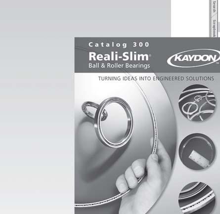


35 KAYDON Corporation 2004 Large Bearing Catalog 390 For latest releases: catalog, software, or CAD drawing downloads, visit our website at Section 6 Appendix
Large Bearing Design Manual and Product Selection Guide
 Large Bearing Design Manual and Product Selection Guide TURNING IDEAS INTO ENGINEERED SOLUTIONS www.kaydonbearings.com Large Bearing Catalog 390 KAYDON Corporation 2004 Table of Contents Page Number Section
Shifting gears: simplify your design with slewing ring bearings
 White Paper Shifting gears: simplify your design with slewing ring bearings Scott Hansen, VP, Manufacturing Planning, Kaydon Bearings, an SKF Group company A slewing ring bearing has rolling elements designed
HS Series. Introduction. Design Features. Availability. Applications
 Introduction slewing ring bearings are similar in size to the RK Series, but have rectangular cross sections, which allows for alternate hole patterns as well as improved stiffness and more capacity. They
Kaydon white paper. Slewing bearing selection, simplified. an SKF Group brand. by Jeff Lauber, engineering specialist
 Slewing bearing selection, simplified by Jeff Lauber, engineering specialist an SKF Group brand Selecting the right slewing bearing Slewing bearings are typically used in applications where their ability
RK Series. Introduction. Design Features. Availability. Applications
 Introduction bearings have a flanged cross-sectione or both rings and range in size from 20 47 inches OD (500 1200 mm). The flanged design reduces weight and provides the equipment designer greater flexibility
An engineering & product selection guide for turntable bearings
 Catalog 390 slewing RING Turntable Bearings Turning Ideas into Engineered Solutions An engineering & product selection guide for turntable bearings www.kaydonbearings.com Slewing Ring / Turntable Bearing
Mounting Overlap Shield. Face Clamps. Gap. Seat Depth. Lead In Chamfer. Loose Fit.
 Mounting Introduction: Reali-Slim thin section ball bearings have a crosssection thickness that is much thinner than standard bearings of the same diameter, and are therefore more sensitive to shaft and
Kaydon bearing solutions for Slewing Ring Bearings
 Catalog 390 An engineering and product selection guide Kaydon bearing solutions for Slewing Ring Bearings www.kaydonbearings.com Conversion Factors English-Metric Metric-English Length 1 in = 25.4 mm 1
TRANSLATION (OR LINEAR)
") 5) Load Bearing Mechanisms Load bearing mechanisms are the structural backbone of any linear / rotary motion system, and are a critical consideration. This section will introduce most of the more common
5) Load Bearing Mechanisms Load bearing mechanisms are the structural backbone of any linear / rotary motion system, and are a critical consideration. This section will introduce most of the more common
SLEWING RING CHARACTERISTICS, APPLICATIONS
 SLEWING RING CHARACTERISTICS, APPLICATIONS Slewing rings are large-sized bearings which are able to accommodate combined load, i.e. axial, radial loads and tilting moment. They are usually provided with
ZERO BACKLASH GEARING
 ZERO BACKLASH GEARING Based on Nexen s innovative Roller Pinion technology, the Geared Bearing comes complete with a gear and a precision grade, high capacity bearing. With a wide range of sizes and ratios,
Why bigger isn t always better: the case for thin section bearings
 White Paper Why bigger isn t always better: the case for thin section bearings Richard Burgess, Les Miller and David VanLangevelde, Kaydon Bearings Typical applications Thin section bearings have proven
CLASSIFICATION OF ROLLING-ELEMENT BEARINGS
 CLASSIFICATION OF ROLLING-ELEMENT BEARINGS Ball bearings can operate at higher speed in comparison to roller bearings because they have lower friction. In particular, the balls have less viscous resistance
Kaydon white paper. The importance of properly mounting thin section bearings. an SKF Group brand. by Rob Roos, Senior Product Engineer
 The importance of properly mounting thin section by Rob Roos, Senior Product Engineer an SKF Group brand Figure 1 Radial Load Reversing Thrust Overturning Moment Thin section ball have a much thinner cross-section
Features of the LM Guide
 Features of the Functions Required for Linear Guide Surface Large permissible load Highly rigid in all directions High positioning repeatability Running accuracy can be obtained easily High accuracy can
Chapter 11 Rolling Contact Bearings
 Chapter 11 Rolling Contact Bearings 1 2 Chapter Outline Bearing Types Bearing Life Bearing Load Life at Rated Reliability Bearing Survival: Reliability versus Life Relating Load, Life, and Reliability
Engineering Precision with Every Revolution SLEWING RINGS & PINIONS
 SLEWING RINGS & PINIONS SLEWING RINGS & PINIONS ISO Registration Information Silverthin is an ISO 9001 registered manufacturer of Thin Section and Slewing Ring bearings, Silverthin Quality Management System
CONTENTS. Speciality Tapered Products
 CONTENTS Products Features / Benefi ts Type C............................................................ B7-2 Special Duty, Hinged Cap............................................... B7-3 All Steel............................................................
ENGINEERED SOLUTIONS Based on Reali-Slim Bearings A N I L L U S T R A T E D M O U N T I N G G U I D E
 ENGINEERED SOLUTIONS Based on Reali-Slim Bearings A N I L L U S T R A T E D M O U N T I N G G U I D E Reali-Slim thin-section bearings have contributed to reductions in weight and size in thousands of
Kaydon white paper The thin section bearing of today
 The thin section bearing of today by Joe Zagar, engineering specialist an SKF Group brand Thin section bearings provide space, save weight The ubiquitous ball bearing was a workhorse of industry throughout
Slotted nut NMG. Housing nut GWR. Bosch Rexroth AG. for economical constructions. a min. 0,3. M A = tightening torque of slotted nut.
 R310EN 3301 (2009.08) Precision Ball Screw Assemblies Bosch Rexroth AG 113 Slotted nut NMG for economical constructions B D d d1 b M A = tightening torque of slotted nut a min. 0,3 Polyamide insert Designation
FUNCTION OF A BEARING
 Bearing FUNCTION OF A BEARING The main function of a rotating shaft is to transmit power from one end of the line to the other. It needs a good support to ensure stability and frictionless rotation. The
The Available Solution CYCLO DRIVE. Gearmotors & Speed Reducers. Series
 The Available Solution CYCLO DRIVE Gearmotors & Speed Reducers 6000 Series WHAT DO YOU THINK OF THIS? THESE ARE THE ADVANTAGES OF THE NEWEST CYCLO, 6000 SERIES: More frame sizes, gear ratios and motor
506E. LM Guide Actuator General Catalog
 LM Guide Actuator General Catalog A LM Guide Actuator General Catalog A Product Descriptions 506E Caged Ball LM Guide Actuator Model SKR.. A2-4 Structure and Features... A2-4 Caged Ball Technology... A2-6
Ball Rail Systems RE / The Drive & Control Company
 Ball Rail Systems RE 82 202/2002-12 The Drive & Control Company Rexroth Linear Motion Technology Ball Rail Systems Roller Rail Systems Standard Ball Rail Systems Super Ball Rail Systems Ball Rail Systems
Track Rollers/ Cam Followers
 Track Rollers/ Cam Followers Page Nomenclature...................................... 460 Introduction....................................... 462 Identification....................................... 462
Precision Modules PSK
 Precision Modules PSK The Drive & Control Company Rexroth Linear Motion Technology Ball Rail Systems Roller Rail Systems Standard Ball Rail Systems Super Ball Rail Systems Ball Rail Systems with Aluminum
Ball. Ball cage. Fig.1 Structure of Caged Ball LM Guide Actuator Model SKR
 Caged all LM Guide Actuator Model Inner block all screw shaft Grease nipple Outer rail all cage all Structure and Features Fig.1 Structure of Caged all LM Guide Actuator Model Caged all LM Guide Actuator
LIGHTWEIGHT AND COMPACT. SERIES SL Nm. single-position multi-position. THE ultimate COUPLING from Nm
 LIGHTWEIGHT AND COMPACT L SAFETY COUPLINGS TOQLIGHT SEIES SL 5 700 Nm THE ultimate COUPLING from 5 700 Nm SEIES SL DESIGN / FEATUES Extremely lightweight construction Up to 60 % weight reduction in comparison
ENGINEERED SOLUTIONS. Bearings. Based on Reali-Slim AN ILLUSTRATED MOUNTING GUIDE
 ENGINEERED SOLUTIONS Based on Reali-Slim Bearings AN ILLUSTRATED MOUNTING GUIDE Reali-Slim thin-section bearings have contributed to reductions in weight and size in thousands of applications since we
Ball splines can be configured for an endless number of automated operations. Demystifying Ball Spline Specs
 Ball splines can be configured for an endless number of automated operations. Demystifying Ball Spline Specs Place a recirculating-ball bushing on a shaft and what do you get? Frictionless movement of
Axial-radial cylindrical roller bearings
 Axial-radial cylindrical roller bearings Designs and variants.............. 320 Bearing data..................... 321 (Boundary dimensions, tolerances) Product table 5.1 Axial-radial cylindrical roller
KINGS COLLEGE OF ENGINEERING DEPARTMENT OF MECHANICAL ENGINEERING
 KINGS COLLEGE OF ENGINEERING DEPARTMENT OF MECHANICAL ENGINEERING QUESTION BANK Sub Code/Name: ME 1352 DESIGN OF TRANSMISSION SYSTEMS Year/Sem: III / VI UNIT-I (Design of transmission systems for flexible
TECHNICAL INFORMATION
 General Nomenclature Spherical Roller Bearings The spherical roller bearing is a combination radial and thrust bearing designed for taking misalignment under load When loads are heavy, alignment of housings
Product overview. 10 Bosch Rexroth Corporation Compact Modules R310A 2602 ( ) Compact Modules CKK. Compact Modules with ball screw drive (CKK)
 Compact Modules CKK. Compact Modules with ball screw drive (CKK)") 10 Bosch Rexroth Corporation R310A 2602 (2008.09) CKK with ball screw drive (CKK) Product overview are precision, ready-to-install linear motion systems characterized by their high performance and compact
10 Bosch Rexroth Corporation R310A 2602 (2008.09) CKK with ball screw drive (CKK) Product overview are precision, ready-to-install linear motion systems characterized by their high performance and compact
10 Thrust ball bearings
 10 Thrust ball bearings Designs and variants.............. 1010 Single direction thrust ball bearings... 1010 Double direction thrust ball bearings.. 1010 Cages............................ 1010 Bearings
Kaydon s Bearing Remanufacturing Program
 www.kaydonbearings.com Turning Ideas Into Engineered Solutions Kaydon s Bearing Remanufacturing Program The Industry's Most Comprehensive Bearing Service Kaydon has been a leading manufacturer of large
Chapter 11. Keys, Couplings and Seals. Keys. Parallel Keys
 Chapter 11 Keys, Couplings and Seals Material taken for Keys A key is a machinery component that provides a torque transmitting link between two power-transmitting elements. The most common types of keys
Sheet 1 Variable loading
 Sheet 1 Variable loading 1. Estimate S e for the following materials: a. AISI 1020 CD steel. b. AISI 1080 HR steel. c. 2024 T3 aluminum. d. AISI 4340 steel heat-treated to a tensile strength of 1700 MPa.
Bearing preload. Preload considerations
 Bearing preload There may be some applications where the bearing arrangement needs to be preloaded i.e. requires a negative operating clearance. In applications such as machine tool spindles, automotive
Slide-Rite & Slide-Rite CR Gearbox
 Gearboxes Gearbox and CR Gearbox Pages 2 through 7 Float-A-Shaft (FAS) Gearbox Pages 8 through 24 Visit www.tolomatic.com for the latest updates, CAD files and ordering. GEARBOXES www.tolomatic.com 1 GEARBOXES
...our linkages, your solution. Rod Ends
 ...our linkages, your solution Technical Information Introduction All of our rod ends incorporate either a plain spherical bearing, ball bearing, or roller bearing. Below is an overview of each type. Plain
Highest Performance: Dyna Series
 Highest Performance: Dyna Series GAM can. If you don t see exactly what you need, let us know. We can modify the Dyna Series gearboxes to meet your needs. Page provides a list of commonly requested modifications
Features of the LM Guide
 Features of the Functions Required for Linear Guide Surface Large permissible load Highly rigid in all directions High positioning repeatability Running accuracy can be obtained easily High accuracy can
CONTENTS. GRIP TIGHT Adapter Ball Bearings
 CONTENTS GRIP TIGHT Adapter Ball Bearings Features / Benefits.................................................... B2-2 How to Order / Nomenclature............................................ B2-4 Selection............................................................
Inner block. Grease nipple. Fig.1 Structure of LM Guide Actuator Model KR
 LM Guide ctuator Model LM Guide + all Screw = Integral-structure ctuator Stopper Housing all screw Inner block Grease nipple Outer rail earing (supported side) Housing Stopper Double-row ball circuit earing
using Class 2-C (Centralizing) tolerances. Jack lift shaft lead tolerance is approximately 0.004" per foot.
 tolerances. Jack lift shaft lead tolerance is approximately 0.004 per foot.") WORM GEAR JACK MODELS WORM GEAR ACTIONJAC JACKS Jack systems are ruggedly designed and produced in standard models with load handling capacities from 1/4 ton to 100 tons. They may be used individually
WORM GEAR JACK MODELS WORM GEAR ACTIONJAC JACKS Jack systems are ruggedly designed and produced in standard models with load handling capacities from 1/4 ton to 100 tons. They may be used individually
CYLINDRICAL ROLLER BEARING CATALOG TIMKEN THRUST AND PLAIN BEARINGS CATALOG
 CYLINDRICL ROLLER BERING CTLOG TIMKEN THRUST ND PLIN BERINGS CTLOG Spherical Plain Bearings SPHERICL PLIN Overview: Timken s spherical plain bearings consist of a spherically ground inner ring housed in
Heavy-Duty Rod Ends - Male with integral spherical plain bearing
 Heavy-Duty Rod Ends - Male with integral spherical plain bearing 65700 Order No. Thread (hand) d 1 l 1 d 2 d 3 d 4 l 2 l 3 X g H7 65700.W0005 Right 5 33 M 5 11,11 18 20 9 14 65700.W0006 Right 6 36 M 6
NSK Standard Ball Screws High Speed SS Series
 NSK Standard Ball Screws igh Speed SS Series NSK s high speed and low noise ball screws provide high-level performance for drive systems of industrial machines such as those used in manufacturing. standard
Precision Modules PSK. The Drive & Control Company
 Precision Modules PSK The Drive & Control Company 2 Bosch Rexroth Coporation Precision Modules PSK R310A 2414 (2008.07) Linear Motion and Assembly Technologies Ball Rail Systems Roller Rail Systems Linear
MAIN SHAFT SUPPORT FOR WIND TURBINE WITH A FIXED AND FLOATING BEARING CONFIGURATION
 Technical Paper MAIN SHAFT SUPPORT FOR WIND TURBINE WITH A FIXED AND FLOATING BEARING CONFIGURATION Tapered Double Inner Row Bearing Vs. Spherical Roller Bearing On The Fixed Position Laurentiu Ionescu,
FEATURES/BENEFITS. Setscrew Ball Bearings. DODGE End Covers
 or over 70 years, DODGE has been talking to mounted bearing users and listening to their needs. This experience lead to the design of the optimum mounted ball bearing. A state-of-the-art facility was built
 DRUM BRAKE RIMS Periodic inspection of drum brake rims is necessary to determine indications of uneven or excessive wear. In general, brake rim failures other that regular wear are caused by brake linings
VIS (Valve-In-Star) Hydraulic Motor
 Hydraulic Motor") VIS (Valve-In-Star) Hydraulic Motor VIS 30 Series VIS 40 Series VIS 45 Series The next step in the evolution of low speed high torque (LSHT) hydraulic motors. EATON Low Speed High Torque Motors E-MOLO-MC001-E5
VIS (Valve-In-Star) Hydraulic Motor VIS 30 Series VIS 40 Series VIS 45 Series The next step in the evolution of low speed high torque (LSHT) hydraulic motors. EATON Low Speed High Torque Motors E-MOLO-MC001-E5
Profi le rail guides LLR
 Profi le rail guides LLR Content The SKF brand now stands for more than ever before, and means more to you as a valued customer. While SKF maintains its leadership as the hallmark of quality bearings throughout
 DEPARTMENT OF MECHANICAL ENGINEERING Subject code: ME6601 Subject Name: DESIGN OF TRANSMISSION SYSTEMS UNIT-I DESIGN OF TRANSMISSION SYSTEMS FOR FLEXIBLE ELEMENTS 1. What is the effect of centre distance
White Paper. Phone: Fax: Advance Lifts, Inc. All rights reserved.
 White Paper TURNTABLE AppLicATioN GUidE This section covers the full range of turntables manufactured by Advance Lifts. The basic information necessary to select an appropriate turntable for an application
Installation Procedures
 For the precision ball and roller bearings supplied by MRC Bearings, skill and cleanliness while handling, mounting and dismounting are necessary to ensure satisfactory bearing performance. As precision
bearings (metric series)
") Taper roller bearings (metric series) 32302 B J2 / Q CL7C Nomenclature 1 2 3 4 1. Contact angle: 3. Features: B Larger contact angle than standard Q Improved friction torque characteristics and raceway
Taper roller bearings (metric series) 32302 B J2 / Q CL7C Nomenclature 1 2 3 4 1. Contact angle: 3. Features: B Larger contact angle than standard Q Improved friction torque characteristics and raceway
LINEAR MOTION SYSTEMS
 R RECISION NDUSTRIAL OMPONENTS R LINEAR MOTION SYSTEMS User-assembled or Pre-assembled PIC now offers a comprehensive line of linear motion systems. Single sourcing eliminates the need for extensive, expensive
Disc Valve Hydraulic Motors 4000 Compact Series
 Disc Valve Hydraulic Motors 10.2014 inspired hydraulics. Änderungen und Druckfehler vorbehalten 10.2014 EN EATON_Motoren english Port B Port A Features Shuttle Valve with Back- Pressure Relief Valve Highlights
CONTENTS. IMPERIAL - IP, ISAF and ISN
 CONTENTS IMPERIAL - IP, ISAF and ISN Features / Benefi ts IMPERIAL.......................................................... B10-3 IMPERIAL-E........................................................ B10-8
CONTENTS. DODGE Plummer Blocks
 CONTENTS DODGE Plummer Blocks Features/Benefits.......................................... B12-2 How To Order............................................. B12-4 Nomenclature.............................................
Engineering Information
 Engineering nformation Gear Nomenclature ADDENDUM (a) is the height by which a tooth projects beyond the pitch circle or pitch line. BASE DAMETER (D b ) is the diameter of the base cylinder from which
Ch# 11. Rolling Contact Bearings 28/06/1438. Rolling Contact Bearings. Bearing specialist consider matters such as
 Ch# 11 Rolling Contact Bearings The terms rolling-contact bearings, antifriction bearings, and rolling bearings are all used to describe the class of bearing in which the main load is transferred through
GatesFacts Technical Information Library Gates Compass Power Transmission CD-ROM version 1.2 The Gates Rubber Company Denver, Colorado USA
 SELECTING SYNCHRONOUS BELTS FOR PRECISE POSITIONING A W Wallin Power Transmission Design February, 1989 Synchronous belts are well known for precise positioning. However, some precision applications require
AUTOFLEX DISC COUPLINGS
 AUTOFLEX DISC COUPLINGS Contents & Coupling Application Configurations Coupling Type Typical Application Series Page No Introduction - Disc Configuration 2 Coupling Selection 3 & 4 Service Factors High
LESSON Transmission of Power Introduction
 LESSON 3 3.0 Transmission of Power 3.0.1 Introduction Earlier in our previous course units in Agricultural and Biosystems Engineering, we introduced ourselves to the concept of support and process systems
Dr. TRETTER AG. Tolerance Rings. safe cost-effective fast assembly
 Dr. TRETTER AG Tolerance Rings safe cost-effective fast assembly Tolerance Rings are corrugated metal strips manufactured of high quality spring steel. Tolerance Rings are a fastening device between two
Gear Engineering Data. Spur Gear Gear Formulas Drive Selection Horsepower and Torque Tables
 Engineering Gear Engineering Data Spur Gear Gear Formulas Drive Selection Horsepower and Torque Tables G-79 Gear Selection Stock Spur Gear Drive Selection When designing a stock gear drive using the horsepower
Specifications. Trantorque GT CALL FAX
 GT Specifications The following pages contain engineering data and product specifications for GT. For CAD drawings of GT, please click on the part number to download the drawing. All drawings are in AutoCAD
Compact Modules. with ball screw drive and toothed belt drive R310EN 2602 ( ) The Drive & Control Company
 The Drive & Control Company") with ball screw drive and toothed belt drive R310EN 2602 (2007.02) The Drive & Control Company Bosch Rexroth AG Linear Motion and Assembly Technologies Ball Rail Systems Roller Rail Systems Linear Bushings
with ball screw drive and toothed belt drive R310EN 2602 (2007.02) The Drive & Control Company Bosch Rexroth AG Linear Motion and Assembly Technologies Ball Rail Systems Roller Rail Systems Linear Bushings
TORQLIGHT SAFETY COUPLINGS
 LIGHTWEIGHT AND COMPACT single-position TOQLIGHT SAFETY COUPLINGS SEIES SL 10 700 Nm THE ULTIMATE COUPLING FOM 10 700 Nm SEIES SL DESIGN / FEATUES Extremely lightweight construction Up to 60 % weight reduction
Highest Precision: Dyna Series
 Highest Precision: Dyna Series GAM can. Just ask! If you don t see exactly what you need, let us know. We can modify the Dyna Series gearboxes to meet your needs. Page 3 provides a list of commonly requested
Highest Precision: Dyna Series
 GAM can. Just ask! If you don t see exactly what you need, let us know. We can modify the Dyna Series gearboxes to meet your needs. Page 3 provides a list of commonly requested modifications to give you
Amerigear SF Spindle
 Amerigear SF Spindle Installation and Maintenance Manual Form No. 381-SH, 4/01 Spindle Installation and Maintenance Manual TABLE OF CONTENTS SECTION TITLE PAGE 1 Introduction...: 3 2 General Information...:
Air Champ RPM DPC-15T DPC-13T DPC-11T DPC-11T DPC-9T DPC-9T DPC-9T DPC-9T DPC-9T DPC-9T DPC-9T DPC-9T DPC-9T DPC-9T DPC-9T DPC-9T DPC-9T DPC-9T
 DUAL PLATE FRICTION CLUTCH SELECTION CHART Friction clutch recommendation is based upon air pressure of 50 psi, transmitted horsepower and speed. RPM 100 200 300 400 500 600 700 800 900 1000 1100 1200
( ) x ( ) SELECTION. IMPERIAL - IP and ISAF Spherical Roller Bearing GENERAL
 x ( ) SELECTION. IMPERIAL - IP and ISAF Spherical Roller Bearing GENERAL") IMPERIAL - ISAF UNIFIED Plummer Sleeve Bearing SLEEVEOIL SELECTION DODGE Spherical Roller Bearings have the capacity carry heavy radial loads and combined radial and thrust loads. The maximum recommended
IMPERIAL - ISAF UNIFIED Plummer Sleeve Bearing SLEEVEOIL SELECTION DODGE Spherical Roller Bearings have the capacity carry heavy radial loads and combined radial and thrust loads. The maximum recommended
LM Guide Radial Type Model SR
 LM Guide Radial Type Model Endplate LM block Grease nipple End seal LM rail 90 Ball Retainer plate Side seal (Optional) Cross section 30 Point of Selection A Point of Design Options Model No. Precautions
TYPE TSC/TLC T SERIES FLEXIBLE DISC COUPLINGS
 TYPE TSC/TLC A Stainless steel flexible discs B Overload collars C Cartridge transmission unit D Anti-fly feature E Anti-corrosion treatment F Hubs with API puller holes G Robust hub bolt H Large shaft
NSR-TBC. LM Guide Self-aligning Type Model NSR-TBC. Point of Selection. Point of Design. Options. Model No. Precautions on Use
 LM Guide Self-aligning Type Model LM casing Spline nut End seal LM rail Grease nipple Side plate Clearance adjustment bolt 90 Side seal (Optional) Ball Retainer Cross section 30 Point of Selection A Point
Disc Valve Hydraulic Motors
 Disc Valve Hydraulic Motors State of the art motors benefiting from years of experience and inovating constantly to fit your demands. C-i Disc Valve Hydraulic Motors Highlights Product Description In the
carriages to carry the load (taking into account any moment loads). Unlike the N series sliders these CS sliders do not have protective side seals.
. Unlike the N series sliders these CS sliders do not have protective side seals.") Light Duty Sliders, size 18 no side seal, front fixing Long Linear s L1918.CS Material Zinc plated steel body. Steel rollers (100Cr6) with metal (2Z) or rubber (2RS) seals. Technical notes To be used with
Light Duty Sliders, size 18 no side seal, front fixing Long Linear s L1918.CS Material Zinc plated steel body. Steel rollers (100Cr6) with metal (2Z) or rubber (2RS) seals. Technical notes To be used with
CONTENTS. Setscrew Ball Bearings
 CONTENTS Features / Benefits... B4-3 How to Order / Nomenclature... B4-5 Selection... B4-6 Selection/Dimensions Pillow Blocks SC - Normal Duty... B4-12 SCAH Air Handling Normal Duty... B4-16 SCB Normal
EXPANSION JOINT SELECTION GUIDE
 EXPANSION JOINT SELECTION GUIDE The proper selection and application of an expansion joint is the determining factor in its operation and life. Improper selection and application will lead to problems
Thomas Disc Couplings Installation and Maintenance Series 52 Sizes with classical disc pack TM (Page 1 of 10) DANGER!
 DANGER!") Thomas Disc Couplings Installation and Maintenance Series 52 Sizes 125-925 with classical disc pack TM (Page 1 of 10) This is the Original Document in English Language Figure 1-1. General Information Thomas
Thomas Disc Couplings Installation and Maintenance Series 52 Sizes 125-925 with classical disc pack TM (Page 1 of 10) This is the Original Document in English Language Figure 1-1. General Information Thomas
Fisher 1051 and 1052 Style H and J Sizes 40, 60 and 70 Rotary Actuators
 Instruction Manual 1051 and 1052 H & J Actuators Fisher 1051 and 1052 Style H and J Sizes 40, 60 and 70 Rotary Actuators Contents Introduction... 1 Scope of Manual... 1 Description... 2 Specifications...
R310EN 2211 ( ) The Drive & Control Company
 The Drive & Control Company") eline Ball Rail Systems R310EN 2211 (2006.04) The Drive & Control Company Bosch Rexroth AG Linear Motion and Assembly Technologies Ball Rail Systems Roller Rail Systems Linear Bushings and Shafts Ball
eline Ball Rail Systems R310EN 2211 (2006.04) The Drive & Control Company Bosch Rexroth AG Linear Motion and Assembly Technologies Ball Rail Systems Roller Rail Systems Linear Bushings and Shafts Ball
Wind Energy Solutions
 Wind Energy Solutions Around the world, wind turbine designers and operators are turning to Timken for power transmission and friction management solutions that increase uptime and improve total system
MRC Bearing Solutions for the Hydrocarbon Processing Industry
 MRC Bearing Solutions for the Hydrocarbon Processing Industry M230-710 February 1996 Table of Contents Selection of the Proper Bearing Solution.................... 1 Relative Bearing Performance Characteristics................
CONTENTS. D-LOK Ball Bearings
 CONTENTS Ball Bearings Features/Benefits.................................................. B5-2 How to Order/Nomenclature......................................... B5-4 Selection........................................................
...components in motion. Miniature Linear Guideways
 ...components in motion Miniature Linear Introduction Miniature linear guideway systems are widely used throughout industry for precise, compact applications. Precise and Stainless The gothic arch shape
TYPE TSC/TLC T SERIES METAL MEMBRANE COUPLINGS
 A Stainless Steel Flexible Discs B Overload Collars C Cartridge Transmission Unit D Anti-Fly Feature E Anti-Corrosion Treatment F Hubs with Puller Holes G Externally Wrenched Bolts H Large Shaft Diameters
SRG. Caged Roller LM Guide Ultra-high Rigidity Type Model SRG. Point of Selection. Point of Design. Options. Model No. Precautions on Use
 Caged Roller LM Guide Ultra-high Rigidity Type Model LM block LM rail End seal Endplate 45 45 Caged roller Roller 45 Cross section 45 * or the caged roller, see. Point of Selection A Point of Design Options
Cross Tensioners. Frames. Bearings. Springs. Mounting Holes. Adjustment Marks
 Cross Tensioners Cross Tensioners provide constant belt or chain tension. Their automatic tensioning action translates into improved performance and extended life for most types of fixed-centre drives.
Highest Performance: Dyna Series
 Highest Performance: Dyna Series The Dyna Series is our highest performance right-angle gear reducer utilizing sophisticated hypoid gearing. The benefit of hypoid gearing is that it combines the space
EPT Mounted Bearing Technical Support. Phone: FAX: Mounted Bearing Application Engineering
 ENGINEERING EPT Mounted Bearing Technical Support Browning Technical Services Phone: 606-564-2093 FAX: 606-564-2079 Mounted Bearing Application Phone: 219-465-2211 FAX: 219-465-2290 E-mail: browningbearing.eng@emerson-ept.com
TOLERANCE, INCHES UP TO 1-1/ /16 TO 2-1/ /2 TO /16 TO /16 TO assistance.
 SPECIAL DUTY-DOUBLE ROW TAPERED ROLLER BEARINGS DODGE Double Row Tapered Roller Bearings have the highest capacity of all DODGE Tapered Roller Bearings. They carry heavy radial loads and combined radial
Instruction Manual for HSPA Take-Up Units
 Installation Instruction Manual for HSPA Take-Up Units Warning: To ensure the drive is not unexpectedly started, turn off and lockout the power source before proceeding. Failure to observe these precautions