FLOW EZY FILTERS A COMPLETE LINE OF HYDRAULIC FILTERS, STRAINERS AND ACCESSORIES
|
|
|
- Edward Barrett
- 6 years ago
- Views:
Transcription


1
2
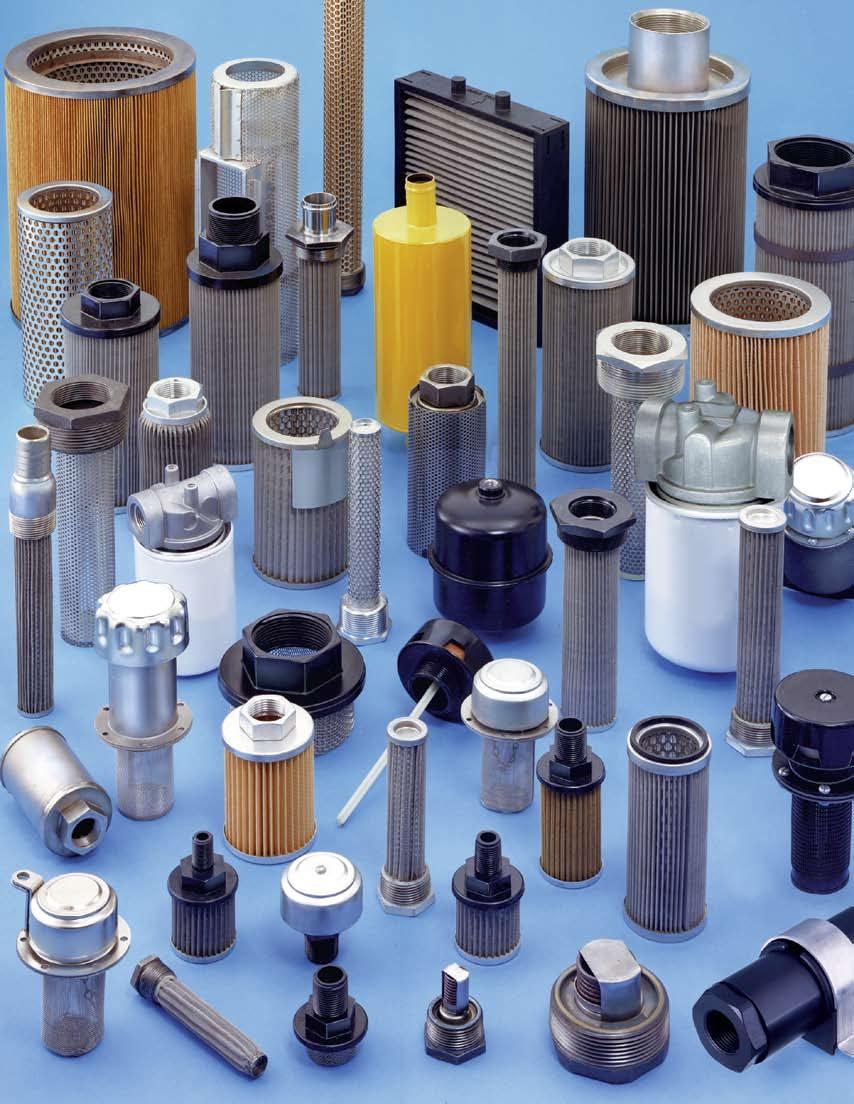
3 A COMPLETE LINE OF HYDRAULIC FILTERS, STRAINERS AND ACCESSORIES We have designed and engineered our complete product line of quality filtration products to meet exacting standards, giving you superior, costeffective performance. We don't just rest on our reputation of providing only the best products, we strive to keep it. If you feel the need to contact us for any reason, we encourage you to do so. As our customer, what you have to say is important to us. If you don't find what you're looking for in these pages, give us a call. We're very experienced in producing "specials" that meet our customers' needs. (We may have already built a model similar to your requirements.) So for any reason, please give us a call. For questions or to place an order, contact us 24 hours a day, 7 days a week by fax or on the internet. We can also be reached by phone 8 AM to 5 PM eastern standard time. Call us at or Fax us at or Or reach us on our website at Or us at flowezy@flowezyfilters.com MasterCard S AMERICAN EXPRESS FLOW EZY FILTERS P.O. Box 1749 Ann Arbor, MI Tel or Fax or
4 SALES AND RETURN POLICY PRICING All prices are FOB Ann Arbor, MI. All pricing subject to change without notice. QUOTES All items not listed in current price lists are subject to quote. All quotes are net cost and are FOB Ann Arbor, MI. Unless otherwise stated all quotes are good for 30 days. Blanket quotes are handled on an individual basis. PAYMENTS Standard terms of payment is net 30 days from date of invoice. All past due accounts are subject to 1-1/2% per month on the unpaid balance. Credit hold may take place at 60 days. GENERAL All clerical errors are subject to correction. RUSH ORDERS (UPS RED, BLUE, ORANGE, FEDERAL EXPRESS, ETC.) Orders must be received no later than 2:00 p.m. Eastern Time in order to be shipped the same day. SHIPMENTS VIA THE POSTAL SERVICE There will be a $25.00 flat additional fee charged for any shipment which requires use of the postal service. SPECIAL ORDERS Special orders may require partial or complete prepayment before beginning production. CANCELLATIONS Special orders for elements that are built to the customer's specifications cannot be canceled if the order is in production, without cancellation charges. ADDITION OF ITEMS TO EXISTING ORDERS Additional items cannot be added to orders that exist but have not shipped. RETURNS No goods may be returned without prior authorization and RGA number given by Flow Ezy Filters,Inc. Shipping discrepancies must be brought to the attention of Flow Ezy Filters within 20 days of receipt of goods. Special orders built to the customer's specifications cannot be returned. All authorized returns must be in the original packaging in the original condition and shipped freight prepaid. Flow Ezy Filters, Inc. reserves the right to issue credit for returned goods upon inspection of the same. Original purchase order, invoice number, and invoice date of the product being returned must be given to Flow Ezy Filters before a Returned Goods Authorization (RGA) number will be given. 2
5 INDEX SUMP STRAINERS Page All-Metal Sump Strainers 4 All-Steel Sump Strainers 4 Nylon Connector Sump Strainers 5 All-Stainless Sump Strainers with Nylon Connector 5 Crimped-End Sump Strainers 6 Disposable Sump Filters 6 CASS and MASS Strainers 7 Double Element Sump Filters 8 WASS Mini Suction Strainers 8 Nylon Suction Strainers 10 Series AN Texas Strainers 9 Tank-Mounted Strainers Flow Diffusers 14 strainer MAGNETS 14 Pipe-mounted suction screens 15 Tank Filler-Breathers Top-Mounting Units 16 Accessories Perforated Inner Guard 16 Magnet and Post 16 Dipstick 20 Padlock Adapted 16 Stainless Steel 16 Removable Basket Units 17 All-Nylon Top-Mounting Units 18 Units for Pressurized Tanks 18 Side-Mounting Units 19 TANK BREATHERS BF Models 20 NBF Models 20 Spin-On Filter Elements 21 Spin-On Air Breather Adapters 21 Giant Tank Breathers 22 Page BACK-PRESSURE INDUCERS 23 JET PNEUMATIC EXHAUST MUFFLERS 23 SPIN-ON FILTERS 24 REUSABLE MAGNETS FOR SPIN-ON 25 REPLACEMENT LUBE FILTERS PSI INLINE FILTERS 26 LOW COST IN-LINE FILTERS 10-GPM In-Line Filters Series and 3000-psi In-Line Filters 28 CARTRIDGE FILTER HOUSINGS 29 MELTBLOWN CARTRIDGES 30 INDUSTRIAL PROCESS FILTER CATRIDGES 31 A 2 -SERIES CARTRIDGE FILTER ELEMENTS 32 FILTERS Y-Filters T-Filters Texas Filters Tee-Ezy Filters HIGH- CAPACITY FILTERS/STRAINERS, Models PLEATED BAGS FOR BAG FILTERS 46 OIL-ABSORBING INSERT CARTRIDGES 47 HYDRAULIC FLANGES 48 PORTABLE OIL TRANSFER AND FILTER SYSTEM 48 HIGH QUALITY WIRE CLOTH 49 REPLACEMENT ELEMENTS OTHER FLOW EZY CATALOGS 83 3

6 SUMP STRAINERS All Metal - All Steel Sump strainers are used in hydraulic fluids, coolants, lubricants, and many process fluids. Flow Ezy offers them in many different constructions to better match a variety of applications. All have strong perforated metal support tubes under the straining elements. All are available with optional, built-in bypass relief valves to avoid starving the pump should the strainer become dirt-clogged. ALL-METAL CONSTRUCTION The traditional all-metal sump strainer has stainless steel pleated elements, in mesh sizes 30 to 200. Continuous epoxybonded joints will not leak fluid around the element. They may be cleaned and used indefinitely. ALL-STEEL CONSTRUCTION All-steel sump strainers (Style AS) provide greater strength. Otherwise they are the same as the standard unit. (Not a stocked item.) REVERSE TAPER EPOXY HOW TO ORDER Select the desired specifications from the ordering table and build an ordering code number, as shown in this sample: AS /2 - NIPPLE RV-3 STYLE - GPM - NPT - CONNECTION - MESH - VALVE (spell out NIPPLE (omit if if wanted) not wanted) STYLE GPM NPT CONNECTION MESH RELIEF (Flow (Pipe (Nut or (Screen VALVE Capability) size) Nipple) size) (Optional) ALL 2 1/4*, 1/2* no 30 METAL 3 3/8, 1/2* symbol RV-3 no symbol 3 3/4 (nut) (3-psi (aluminum 5 3/4, 1 60 bypass) thd. end) 10 3/4, 1 nipple /4 (to get ALL /2 nipple 100 STEEL /2&2 you must RV-5 AS /2 specify it) (5-psi bypass) *Relief Valve not available (Pressure drop through a clean element will not exceed 0.2 psi (0.4-in. Hg) at rated flow of 150 SSU viscosity fluid and 100 mesh.) DIAMETER NUT STYLE (All-steel construction) GPM SCREEN AREA NPT OVERALL RATING (Sq. Inches) (Pipe DIMENSIONS Size) Diameter Length /8, 1/2, 3/4 2-1/8 2-11/ /4, 1, 1-1/4 3-1/16 3-1/ /4, 1, 1-1/4 3-1/16 5-5/ /4, 1, 1-1/4 3-1/16 7-1/ /2 4-1/16 9-5/ /2 & 2 4-1/16 9-5/ /2 5-1/ / / /8 Slot holding epoxy adhesive has a reverse taper on both sides to ensure a positive interlock on all strainers. Magnets Available- See Page 14 LENGTH NUT STYLE (Metal construction w/cast aluminum top) GPM SCREEN AREA NPT OVERALL RATING (Sq. Inches) (Pipe DIMENSIONS Size) Diameter Length /4,1/2 1-1/ /8, 1/2, 3/4 2-1/8 2-11/ /4 & 1 3-9/32 3-1/ /4, 1, 1-1/4 3-9/32 5-3/ /4,1, 1-1/4 3-9/32 7-3/ /2 4-9/32 9-3/ /2 & 2 4-9/32 9-3/ /2, 3 5-7/ / /2, 3 5-7/ / / /4 NIPPLE STYLE (All-metal construction) DIAMETER GPM SCREEN AREA NPT OVERALL RATING (Sq. Inches) (Pipe DIMENSIONS Size Diameter Length LENGTH /4,1/2 1-1/4 4-3/ /8, 3/4 2-1/16 2-7/ /4, 1 3-1/ / / /4 3-1/16 7-9/ / / /2, / /2, 3 5-1/ / /2, 3 5-1/ /4 4
 (omit if not wanted) STYLE GPM NPT CONNECTION MESH VALVE (Flow (Pipe (Nut or (Screen (Optional) Capacity) size) Nipple) size) 2")
7 SUMP STRAINERS Nylon Connector HOW TO ORDER Select the desired specifications from the ordering table and build an ordering code number, as shown in this sample: P NIPPLE RV-3 STYLE - GPM - NPT - CONNECTION - MESH - VALVE (spell out NIPPLE if wanted) (omit if not wanted) STYLE GPM NPT CONNECTION MESH VALVE (Flow (Pipe (Nut or (Screen (Optional) Capacity) size) Nipple) size) 2 1/8,1/4,3/8,1/2 Nut Only 3 1/4 P Nut or Nipple (std. 3 3/8,1/2, 3/4 (to get nipple you 30 RV-3 Nyl-End) must specify it) (3-psi bypass) 60 PASS 5 3/4, 1, 1-1/4 Nut (S.S. 10 3/4, 1, 1-1/4 no symbol Nyl-End) 20 3/4, 1, 1-1/4 100 RV /2 & 2 Nipple Style (5-psi /2 & 2 (see chart below) bypass) /2 Nipple Only /2 Nut or Nipple (to get nipple you must specify it) NYLON CONNECTOR TYPE Nyl-End sump strainers (Style P) are made with the same selection of stainless steel elements as the standard all-metal units. They differ in that the connector end pieces are molded in a single piece of glassreinforced nylon resin. Pleated stainless elements are epoxybonded in place. They're as serviceable as all-metal units, but they cost 12 to 50 percent less, depending on size. ALL-STAINLESS CONSTRUCTION All-stainless-steel sump strainers with nylon connectors (Style PASS) are available in the same wide variety of sizes and element mesh sizes as the standard Nyl-End units. For excellent resistance to oxidation and corrosion. (Not always a stocked item.) (Pressure drop through a clean element will not exceed 0.2 psi (0.4-in. Hg) at rated flow of 150 SSU viscosity fluid.) NUT STYLE NIPPLE STYLE GPM SCREEN AREA NPT OVERALL RATING (Sq. Inches) (Pipe DIMENSIONS Size) Diameter Length DIAMETER GPM SCREEN AREA NPT OVERALL RATING (Sq. Inches) (Pipe DIMENSIONS Size) Diameter Length DIAMETER /8,1/4,3/8,1/2 1-5/8 4-3/ /4,3/8,1/2,3/4 2-1/4 2-11/ /4, 1, 1-1/4 3-3/16 3-1/ /4, 1, 1-1/4 3-3/16 5-3/ /4, 1, 1-1/4 3-3/16 7-3/ /2, 2 4-3/16 9-3/ /2, 2 4-3/16 9-3/ /2, 3 5-3/ / /2, 3 5-3/ / / /4 LENGTH /8, 1/2, 3/4 2-1/4 3-3/ / / / /2 4-3/ / / / /2 4-3/ / / /8 50* /2 4-3/ / /2, 3 5-3/ / /2, 3 5-3/ / /16 19 LENGTH *No hex between nipple and strainer on this part Magnets Available- See Page 14 REVERSE TAPER EPOXY Slot holding epoxy adhesive has a reverse taper on both sides to ensure a positive interlock for strongest possible connection. 5

 not wanted) GPM NPT CONNECTION MESH VALVE STYLE (Flow (Pipe (Nut or (Screen (Optional) Capacity) Size) Nipple) Size) C 5 3/4 no symbol 30 RV-3 (Crimped)")
8 SUMP STRAINERS Crimped End and Disposable CRIMPED-END STRAINERS These are truly all-metal sump strainers, as they do not have any epoxy in their construction. The stainless steel elements are secured through strong mechanical crimping. Good for almost any fluid, especially those that attack epoxy materials. Also for high-temperature applications. HOW TO ORDER Select the desired specifications from the ordering table and build an ordering code number, as shown in this example: C NIPPLE RV-3 STYLE - GPM - NPT - CONNECTION - MESH - VALVE (spell out NIPPLE (omit if if wanted) not wanted) GPM NPT CONNECTION MESH VALVE STYLE (Flow (Pipe (Nut or (Screen (Optional) Capacity) Size) Nipple) Size) C 5 3/4 no symbol 30 RV-3 (Crimped) 10 1 (nut) (3-psi /4 60 bypass) /2 To get NIPPLE /2 you must 100 RV-5 2 specify it (5-psi /2 200 bypass) (Pressure drop through a clean element will not exceed 0.2 psi (0.4-in. Hg) at rated flow of 150 SSU viscosity fluid.) NUT STYLE NPT OVERALL GPM SCREEN AREA (Pipe DIMENSIONS RATING (Sq. Inches) Size) Diameter Length /4 & 1 2-7/8 3-1/ /8 5-3/ /4 2-7/8 7-1/ /2 3-7/8 9-5/ /2 & 2 3-7/8 9-5/ / / /16 DIAMETER LENGTH DISPOSABLE FILTERS These sump filters eliminate the need for cleaning. When fitted with a 10 or 20-micron paper (cellulose) element, they have three times the the dirt carrying capacity of a 74 micron metal screen type. When a 40-micron synthetic fiber element is used, the capacity is six times as great as with the metal units. The pleated paper element is fully supported by a perforated metal tube. These disposable-type sump strainers can also be used as replacement filter elements in many filter housings (that provide a male NPT connection). HOW TO ORDER Select the desired specifications from the ordering table and build an ordering code number, as shown in this example: CS - 3-3/ RV-5 STYLE - GPM - NPT - MICRONS - VALVE (omit if not wanted) GPM NPT STYLE (Flow (Pipe MICRON VALVE Capacity) Size) (Nominal) (Optional) CS 1 1/2 10C* RV-3 (paper) 3 3/4 20C* (3-psi bypass) 40A RV (5-psi bypass) *Cellulose Synthetic (Pressure drop through a clean element will not exceed 0.5 psi (1-in. Hg) at rated flow of 150 SSU viscosity fluid.) NIPPLE STYLE DIAMETER NPT OVERALL GPM SCREEN AREA (Pipe DIMENSIONS RATING (Sq. Inches) Size) Diameter Length /4 2-7/8 3-1/ /8 5-3/ /4 2-7/8 7-5/ /2 3-3/4 9-5/ /2 3-3/4 9-5/ / / /8 DIAMETER LENGTH FILTERING OVERALL GPM AREA MICRONS DIMENSIONS RATING (Sq. In.) (Nominal) (Absolute) Diameter Length ,20,40 40,50, / ,20,40 40,50, / / ,20 40,50 4-1/2 14 LENGTH Magnets Available- See Page 14 6
 not wanted) STYLE GPM NPT CONNECTION MESH VALVE (Flow (Pipe (Nut or (Screen (Optional) Capability) size)")
 bypass) (Pressure drop through a clean element will not exceed 0.2 psi (0.4-in. Hg) at rated flow of 150 SSU viscosity fluid and 100 mesh.")
9 SUMP STRAINERS All Stainless Steel HOW TO ORDER Select the desired specifications from the ordering table and build an ordering code number, as shown in this sample: CASS /2 - NIPPLE RV-3 STYLE - GPM - NPT - CONNECTION - MESH - VALVE (spell out NIPPLE (omit if if wanted) not wanted) STYLE GPM NPT CONNECTION MESH VALVE (Flow (Pipe (Nut or (Screen (Optional) Capability) size) Nipple) size) CASS 5 3/4,1,1-1/4 no 30 RV /4,1,1-1/4 symbol (3-psi 20 3/4,1,1-1/4 (coupling) 60 bypass) / /2 & 2 nipple /2 (to get nipple RV you must 200 (5-psi specify it) bypass) (Pressure drop through a clean element will not exceed 0.2 psi (0.4-in. Hg) at rated flow of 150 SSU viscosity fluid and 100 mesh.) CASS SERIES ALL STAINLESS STEEL This all stainless steel crimped sump strainer comes in mesh sizes 30 to 200. Perforated inner support assures a strong, long-lasting strainer that can be cleaned and used indefinitely. Magnets Available- See Page 14 COUPLING STYLE NPT OVERALL GPM SCREEN AREA (Pipe DIMENSIONS RATING (Sq. Inches) Size) Diameter Length /4,1,1-1/4 2-7/8 3-1/ /4,1,1-1/4 2-7/8 5-7/ /4,1,1-1/4 2-7/8 7-3/ /2 3-3/4 8-13/ /2 3-3/4 9-5/ /4 9-5/ / / /2 DIAMETER LENGTH DIAMETER LENGTH NIPPLE STYLE NPT OVERALL GPM SCREEN AREA (Pipe DIMENSIONS RATING (Sq. Inches) Size) Diameter Length /4 2-7/8 3-1/ /8 5-3/ /4 2-7/8 7-5/ /2 3-3/4 9-5/ /2 3-3/4 9-5/ /4 9-5/ / / /8 HOW TO ORDER Select specifications from the ordering table and build ordering code: STYLE GPM NPT CONNECTION MESH VALVE (Flow (Pipe (Nut or (Screen (Optional) Capability) size) Nipple) size) MASS 2 3/8,1/2 no 30 RV-3 3 3/8,1/2,3/4 symbol (3-psi 5 3/4,1,1-1/4 (coupling) 60 bypass) 10 3/4,1,1-1/4 20 3/4,1,1-1/4 nipple /2 (to get nipple RV /2,2 you must 200 (5-psi /2 specify it) bypass) MASS SERIES ALL STAINLESS STEEL All stainless steel sump strainers with continuous epoxy-bonded end caps. Magnets Available- See Page 14 COUPLING STYLE NPT OVERALL GPM SCREEN AREA (Pipe DIMENSIONS RATING (Sq. Inches) Size) Diameter Length /8,1/ / /8,1/2,3/4 2-1/ / /4,1,1-1/4 3-1/16 3-1/ /4,1,1-1/4 3-1/16 5-9/ /4,1,1-1/4 3-1/16 7-1/ /2 4-1/16 8-3/ /2 4-1/16 9-5/ /16 9-5/ /2 5-1/ / / /8 DIAMETER LENGTH DIAMETER LENGTH NIPPLE STYLE NPT OVERALL GPM SCREEN AREA (Pipe DIMENSIONS RATING (Sq. Inches) Size) Diameter Length /8,1/ / /8,1/2,3/4 2-1/32 2-7/ /4,1 3-1/ / /4,1,1-1/4 3-1/ /4 3-1/16 7-9/ /2 4-1/16 9-3/ /2 4-1/ / / / /2 5-1/ / / /4 7


10 DOUBLE ELEMENT SUMP FILTERS SUCTION STRAINERS REPLACES PRODUCTS FOR: Michigan Fluid Power (MFP) Fluid Power Products Ambac Fluid Power Fluid Power Systems These high-quality sump filters meet the special requirements for use with hydraulic oils, coolants, lubricants, and fireresistant fluids. They have a unique dual-element construction that provides a much larger filtering area than standard units. This greater filtration capacity makes them ideal for use in the following industries: agriculture, construction, general industrial, material handling, chemical, petroleum, machine tool & metalworking, and processing. "WASS" style sump strainers are mini-type, welded, and all 304 stainless steel for virtually any fluid compatibility issues. The ends are secured through mechanical crimping. No epoxy is used in the manufacturing of these units. For low-flow applications. HOW TO ORDER Select the desired specifications from the ordering table and build an ordering code number, as shown in this example: PORT ELEMENT HEX GPM SIZE AREA A B C D NPT SQ. IN /8 4-1/16 3-1/ /8 5-1/16 4-1/ / /16 5-1/ / /4 6-1/16 5-1/ /4 7-1/16 6-1/ / /16 7-1/16 6-1/ /16 7-1/ /16 9-1/4 5 HOW TO ORDER DUAL ELEMENT SUMP FILTERS A D C B WASS - 3-1/2 - NIP RV-3 STYLE - GPM - NPT - CONNECTION - MESH - VALVE (spell out NIP (omit if if wanted) not wanted) GPM NPT CONNECTION MESH VALVE STYLE (Flow (Pipe (Nut or (Screen (Optional) Capacity) Size) Nipple) Size) WASS 3 3/8 no symbol 30 no symbol (coupling) (omitted) 1/2 60 NIP RV-3 3/4* (nipple) 100 (3-psi) * 3/4 coupling not available ** 50 x 200 mesh available 200** RV-5 (5-psi) Select the desired specifications from the data below and build an ordering code number, as shown in the example: 2-1/2 SR / RV-3 STYLE - GPM - NPT - MESH - VALVE (omit if not wanted) STYLE GPM NPT MESH VALVE (Flow (Pipe (Screen (Optional) Capacity) Size) Size) NPT LENGTH COUPLING NIPPLE 3/8 3-1/16 3-1/2 1/2 3-1/4 3-1/2 3/4 N/A 3-1/2 1-3/4 2-1/2 A SU RV-3 without 15 1 (3-psi bypass /4 bypass) SR /2 100 with 50 2 bypass / /4 A (Pressure drop through a clean element will not exceed 0.2 psi (0.4-in. Hg) at rated flow of 150 SSU viscosity fluid and 100 mesh.) Magnets are available, order separately. Magnets Available- See Page 14 WASS Nipple WASS Coupling 8

11 TEXAS STRAINERS HOW TO ORDER Select the desired specifications from the ordering table and build an ordering code number, as shown in this sample: N RV-3 - ALSS GPM - NPT - CONNECTION - DIA. - MESH - VALVE - STYLE GPM NPT CONNECTION DIA. MESH VALVE STYLE (Flow (Pipe (Coupling or (In.) (Screen (Optional) Capacity) Size) Nipple) Size) no symbol RV-3 ALSS 3 (coupling) (3-psi (all stainless bypass) steel- 6 omit if not N wanted) 4 (nipple) 200 RV-5 6 (5-psi bypass) *Bypass valve will not handle 100% of rated flow. These are BIG suction strainers that screw into reservoir suction pipes as large as six inches in diameter, to handle flow rates as high as 600 gpm. Stainless wire screens as fine as 200 mesh and either male (nipple) or female (coupling) connections may be ordered. Each flow size is offered in more than one length/diameter ratio size, to better fit your available space. Standard Texas strainers are made with mild steel support tubes, end caps, and fittings. They re epoxy bonded for leak-proof service. FLOW RATINGS (based on 150 SUS oil) 200 GPM 300 GPM 400 GPM 600 GPM ELEMENT AREA (sq. in. of wire cloth) OUTSIDE DIAMETERS (in.) OVERALL LENGTHS (in.) With 2" COUPLING 13-5/8 10-3/16 8 Call 2" NIPPLE 14-3/4 11-5/16 9-1/8 Factory DIMENSION TABLE 3" COUPLING 14-3/4 11-5/16 9-1/8 18-1/ /4 11-5/16 3" NIPPLE 15-1/ /16 9-1/2 18-7/ / /16 4" COUPLING 15-9/ /16 9-3/8 18-7/ / /4 18-3/ / / /16 4" NIPPLE 15-13/ /16 9-5/8 19-1/8 15-1/ / / / / /16 6" COUPLING 12-5/8 9-7/ / /4 15-7/ /4 20-7/16 6" NIPPLE 12-3/ /8 12-3/ /8 15-9/ /8 20-9/16 Magnets Available- See Page 14 ALL-STAINLESS CONSTRUCTION Texas strainers are available constructed entirely of stainless steel, in the same wide variety of sizes and element mesh sizes as the standard units. 9

12 NYLON SUCTION STRAINERS SERIES AN-6235 ECONOMICAL DISPOSABLE ALL-NYLON CONSTRUCTION 30 MESH-SIZE EQUIVALENT CORROSIVE RESISTANT DISPOSABLE AND CLEANABLE LINE TYPE FILTER ELEMENTS These all-nylon suction strainers are ideal for use where stainless steel or other metal strainers might corrode or contaminate your fluid. Such applications include water/ seawater/de-ionized water, medical/pharmaceutical, general industrial, chemical, and coolant/lubricant. They are available in nut or nipple sizes in flow rates to 3 GPM. The nut style is available in 5 pipe sizes, while the nipple is available in 3. Their unique construction, molded from nylon, offers the equivalent retention of 30 mesh woven wire. That low-cost construction also makes them economical, easy-to-use, and disposable, saving you time and money. HOW TO ORDER NYLON SUCTION STRAINERS Select the desired specifications from the ordering table and build an ordering code number, as shown in this sample: NYL - 3-1/2 - NUT - 30 STYLE - GPM - NPT - CONNECTION - MESH 1-3/8 2-1/4 1-3/8 2-1/4 STYLE GPM NPT CONNECTION MESH (Pipe Size) (Nut or Nipple) (Screen Size) 1/8 1/4 3/8 Nut NYL 3 1/2 30 3/4 NPT NPT 3/8 1/2 Nipple 3/4 3-5/8 4-5/16 3-5/8 5-5/ / /16 FLOW EZY OLD A B C O-RING PART NO. FLOW EZY NO. PART NO. AN PART NO. AN A AN A-03G / / AN A-10C AN A-25W AN A-40W AN A-74W AN A-149W AN A-238W 9133 AN A-590W M AN PART NO. AN A AN A-03G 4-5/ / C 25W 40W 74W 149W 238W 590W AN PART NO. AN A AN A-03G G 3-7/ / C C 10W W 25W W 40W W 74W W 149W W 238W W 590W W AN PART NO. AN A AN A-03G G 4-7/ / C C 05W W 10W W 25W W 40W W 74W W 149W W 238W W 590W MESH A C O.D. B DIA. OPTIONAL NITRILE (BUNA) SEALS INCLUDED 10

13 TANK-MOUNTED STRAINERS A tank-mounted strainer (either suction or return) can be installed through a tank top by welding a standard bell reducer (coupling) over a hole cut in the top. A standpipe, threaded into the coupling, need be only long enough to stay below the lowest fluid level encountered. The strainer may be removed for servicing without draining the tank. Flow Ezy tank-mounted strainers and diffusers install through the side wall, or through the tank top and into a standpipe. Either way, they can be removed through the hole in which they are mounted, and access to the tank interior is not necessary. They re made in three styles: for suction straining, return-line straining, or return-line diffusion. Diffusers have no wire cloth elements; their function is to reduce foaming, tank noise, need for baffling plates, and pump cavitation caused by flow disturbance at the pump inlet. Strainer elements are offered in 30, 60, l00, or 200 mesh size. Bypass relief valves can be supplied, built in. These products most commonly have a male NPT, to mount to the tank. A male SAE straightthread is also offered. Several methods of connecting fluid lines exist, the most common being into a female NPT. (A female SAE straight-thread is also offered.) Hose connections, either beaded or barbed, are available too. There s a wide choice of materials of construction. The standard (and least costly) units have a cast iron bushing, steel support tube, and stainless steel wire cloth element. Also offered are models with forged steel bushings, or an all-welded, all stainless steel unit (no epoxy). A return-line strainer like that shown (or a suction strainer or flow diffuser) can be mounted through a tank wall. For ordering information, see next pages. Although designed for mounting through walls, these strainers can also be adapted to in-line use. Using standard pipe fittings like those shown, a housing for a strainer can be quickly assembled. 11
14 TANK-MOUNTED STRAINERS Dimensions HOW TO ORDER - Select desired specifications from ordering table and build ordering code number, as shown in sample: SAMPLE: S RV-5 STYLE - GPM - MESH - VALVE STYLE CONSTRUCTION GPM (FLOW CAPACITY) MESH (SCREEN SIZE) VALVE (OPTIONAL) SUCTION S SFS SASW ST Iron construction, metal support tube, epoxy bonded Forged steel bushings, metal support tube, epoxy bonded All-stainless steel, all welded (no epoxy) Straight-thread steel bushing, metal tube, epoxy bonded 4,5,10,15,25,50,100 5,10,15,25 30,60,100,200 RV-3 (3-psi bypass) RV-5 (5-psi bypass) RETURN R RFS RASW RT Iron bushings, metal support tube, epoxy bonded Forged steel bushings, metal support tube, epoxy bonded All-stainless steel, all welded (no epoxy) Straight-thread steel bushing, metal tube, epoxy bonded 5,10,15,25 19,33,54,94,200,462 19,33,54,94 30,60,100,200 RV-15 (15-psi bypass) DIFFUSER D DFS DASW DT Iron bushings, perforated metal, epoxy joint Forged steel bushings, perforated metal, epoxy joint All-stainless steel, all welded (no epoxy) Straight-thread steel bushing, perforated metal, epoxy joint 20,34,55,95,209,464 20,34,55,95 (No wire mesh element) N/A Flow ratings are based on use of schedule 40 pipe. SUCTION (Style S) FOR PIPE LINE CONNECTION B C (Male NPT) D (Female NPT) C (Male SAE St-Thread) D (Female SAE St-Thread) B C (Male NPT) D (Female NPT) A STYLE S (stock item) STYLE SFS (Not stocked) SCREEN GPM A B C D E C D E AREA (in 2 ) (NPT) (NPT) (Approx.) (SAE Thd.) (SAE Thd.) (Approx.) 4 4-1/4 13/16 1-1/ / /4 1-1/32 1 1/2 1-1/16 1-5/ / /4 1-11/32 1-1/4 3/4 1-1/4 1-5/ / / /32 1-1/ /16 1-7/ / /4 2-1/ /4 1-5/16 2-1/ / / /4 3-3/ / / /4 E E STYLE ST (Not stocked) A STYLE SASW (Not stocked) SCREEN GPM A B C D E AREA (in 2 ) (NPT) (NPT) (Approx.) /8 1-1/8 1 1/2 1-1/ /4 1-11/32 1-1/4 3/4 1-3/ /2 1-21/32 1-1/ / /8 1-7/ /4 1-1/ /4 3-3/ / /8 E RETURN (Style R) B C (Male NPT) D (Female NPT) C (Male SAE St-Thread) D (Female SAE St-Thread) B C (Male NPT) D (Female NPT) G A E STYLE R (stock item) STYLE RFS (Not stocked) E STYLE RT (Not stocked) G SCREEN GPM A B C D E C D E AREA (in 2 ) (NPT) (NPT) (Approx.) (SAE Thd.) (SAE Thd.) (Approx.) 7/ /4 1-1/32 1 1/2 1-1/16 1-5/ / /4 1-11/32 1-1/4 3/4 1-1/4 1-5/ / / / /32 1-1/ /16 1-7/ / / /4 2-1/ /4 1-5/16 2-1/ / / / /4 3-3/ / / /4 A STYLE RASW (Not stocked) SCREEN GPM A B C D E AREA (in 2 ) (NPT) (NPT) (Approx.) /8 7/8 1 1/2 1-1/ /4 1-1/8 1-1/4 3/4 1-3/ /2 1-3/8 1-1/ / /8 1-5/ /4 1-1/ /4 2-7/ / / //8 E DIFFUSER (Style D) B C (Male NPT) D (Female NPT) C (Male SAE St-Thread) D (Female SAE St-Thread) B C (Male NPT) D (Female NPT) 12 A E STYLE D (Stock item) STYLE DFS (Not stocked) E STYLE DT (Not stocked) PERF. OPEN GPM A B C D E C D E AREA (in 2 ) (NPT) (NPT) (Approx.) (SAE Thd.) (SAE Thd.) (Approx.) /4 7/8 1 1/2 1-1/16 1-5/ / /4 1-1/8 1-1/4 3/4 1-1/4 1-5/ / /16 1-1/4 1-1/ /16 1-7/ / /4 1-9/ /4 1-5/16 2-1/ / / /4 3-3/ / / /4 A STYLE DASW (Not stocked) PERF. OPEN GPM A B C D E AREA (in 2 ) (NPT) (NPT) (Approx.) /8 7/8 1 1/2 1-1/ /4 1-1/8 1-1/4 3/4 1-3/ /2 1-1/4 1-1/ / /8 1-9/ /4 1-1/ /4 2-7/ / / /8 E
15 TANK-MOUNTED STRAINERS Dimensions HOW TO ORDER - Select desired specifications from ordering table and build ordering code number, as shown in sample: SAMPLE: SHO RV-3 STYLE - GPM - MESH - VALVE STYLE CONSTRUCTION GPM (FLOW CAPACITY) MESH (SCREEN SIZE) VALVE (OPTIONAL) SUCTION RETURN SHO Steel bushing, metal support tube, epoxy bonded 5,10,15,25,50 30,60,100,200 RHO Steel bushing, metal support tube, epoxy bonded 19,33,54,94,200 30,60,100,200 RV-3 (3-psi bypass) RV-5 (5-psi bypass) RV-15 (15-psi bypass) DIFFUSER DHO Steel bushing, metal support tube, epoxy bonded 20,34,55,95 (No wire mesh element) N/A Flow ratings are based on use of schedule 40 pipe. B FOR HOSE LINE CONNECTION C (Male SAE St-Thread) D (Beaded Hose) SUCTION A E STYLE SHO (Special, not stocked) SCREEN GPM A B C D E AREA (in 2 ) (SAE Thd.) (Hose ID) (Approx.) /4 1-1/32 1-5/ /2 2-1/ /4 1-11/32 1-5/8-12 3/4 2-5/ / /32 1-7/ / /4 2-1/32 2-1/ /4 2-1/ /4 2-1/32 2-1/ /2 2-1/ /32 3-3/ B C (Male SAE St-Thread) D (Beaded Hose) RETURN A B B G A STYLE RHO (Special, not stocked) G SCREEN GPM A B C D E AREA (in 2 ) (SAE Thd.) (HOSE ID) (APPROX,) 7/ /4 1-1/32 1 1/2 2-1/ /4 1-11/32 1-1/4 3/4 2-5/16 1-1/ / /32 1-7/ /16 1-1/ /4 2-1/32 2-1/ /4 2-1/2 1-1/ /32 3-3/ E C (Male SAE St-Thread) D (Beaded Hose) DIFFUSER WELD RING - ORDER SEPARATELY THREAD SIZE 1-1/ / / / / / /8-12 MODEL NUMBER 8632-WR ST-5-WR ST-10-WR ST-15-WR ST-25-WR ST-30-WR ST-50-WR A 2-1/4 2-3/8 2-11/ /2 3-1/2 4-5/8 B 1-3/8 1-11/ /4 2-5/8 2-5/8 3-5/8 A STYLE DHO (Special, not stocked) E PERFORATION GPM A B C D E AREA (in 2 ) (SAE Thd.) (Hose ID) (Approx.) /4 7/8 1-5/ /2 2-1/ /4 1-1/8 1-5/8-12 3/4 2-5/ /16 1-1/4 1-7/ / /4 1-9/16 2-1/ /4 2-1/2 13

16 FLOW DIFFUSERS STRAINER MAGNETS Flow diffusers are for hydraulic high-speed return lines, to slow down fluids entering the reservoir. They help cure foaming problems and prevent cavitation caused by flow disturbance at the pump inlet. They allow greater freedom in reservoir design, and may even eliminate the need for tank baffling plates. They also reduce reservoir noise. The unit is of all-steel welded construction, and may be ordered with nut or nipple connector. HOW TO ORDER MODEL Length Diameter D /8 3-3/16 D-33 Nipple 4-5/16 D /8 3-3/16 D-54 Nipple 6-9/16 D /16 3-3/16 D-94 Nipple 8-1/8 D /16 4-1/8 D-127 Nipple 9-3/4 D /16 4-1/8 D-210 Nipple 10-3/8 D /16 5-1/4 D-300 Nipple 13-1/16 D /16 5-1/4 D-460 Nipple 13-1/16 D /4 8-1/4 DIAMETER PERFORATIONS 240 LENGTH Flex-Wrap Magnets make sump strainers work better. These flexible magnets wrap around strainer elements to help catch tiny iron particles which might otherwise get through the mesh, thus improving strainer performance. They are easy to install, easy to remove for cleaning, and easy to clean (just wipe with a cloth). They don't block the pleats of the strainer; they just touch the tops. Flex-Wrap Magnets are available in sizes for use on strainer elements with: 2-in. OD (3-gpm strainer), 3-in. OD (5-, 10- & 20-gpm strainers), 4-in. OD (30- & 50-gpm strainers), 5-in. OD (75- & 100-gpm strainers), and 6, 8 and 10-in. OD (for Texas strainers). Many other sizes available. Call factory. RECOMMENDED USAGE ON FLOW EZY STRAINERS IS (Order by OD): For Strainer Element Recommended OD (in.) GPM Number of Magnets ,10, , , ,8,10 Texas Strainer 4 ENGINEERING DATA Return Total Open Ratio Flow Connector Area of of Area Model at 20 ft. Size Perforations Performations: No.* Per Sec.** NPT Each PIPE GPM.093" Dia. D /4 5 Sq. In. 8.8:1 D Sq. In. 13:1 D /4 16 Sq. In. 11:1 D /2 26 Sq. In. 13:1 D Sq. In. 8.3:1 D /2 48 Sq. In. 10:1 D Sq. In. 6.5:1 D & 6 SPECIAL ORDER ONLY *When ordering a NIPPLE connection, add word NIPPLE to model number **Returning fluid speed, based on use of Schedule 40 pipe. 14


17 PIPE-MOUNTED SUCTION SCREENS MESH SIZE TABLE U.S. MESH INCHES MICRONS /30* /30* /30* Suction screens can be used for straining oil, chemical liquids, and water. They will not rust. They re made of tough glass-filled nylon resins with stainless steel wire cloth elements. With male or female NPT connectors, to thread into or onto pipe. There are ten wire mesh sizes to choose from. The finer 60-, 100-, and 200-mesh size screens are backed up with a heavier 30-mesh inner support. *The "30" stands for the mesh size of the support screen. HOW TO ORDER NUT STYLE STRAINERS PART NPT SCREEN DIMENSIONS NO. (Pipe AREA Size) (Sq. in.) A B C HEX F-01 1/ /2 1-5/ /8 F-02 1/4 F-03 3/8 F-04 1/2 F-1 1/ /2 2-1/4 1-1/2 1-3/8 F-2 1/4 F-3 3/8 F-4 1/2 F-5 3/4 F-6 3/ /8 3-3/16 2-1/2 1-3/8 F /8 F /4 2 F / /8 4-3/16 3-1/2 2-1/4 F /4 F / /2 5-3/16 4-1/2 3-1/4 F Choose a part number from the nut or nipple table and add the mesh size desired from the mesh size table located above. Example: A 2-in. nut-style strainer is part number F-16, and ordering it with a 20-mesh wire screen would add 20 to the part number, making it F C B ALL STAINLESS STEEL SUCTION SCREEN Perfect for straining paint, petroleum based fluids, chemical liquids, or water. Not affected by temperature, will not strip, pull loose, or crack. 2-1/4" OD x 1-1/2" tall HOW TO ORDER: Example: F6-30/8 - SS Model No. 1/2" NPT = F4 3/4" NPT = F6 1" NPT = F8 NIPPLE STYLE STRAINERS PART NPT SCREEN DIMENSIONS NO. (Pipe AREA Size) A B C M3 3/ /2 2-1/4 1-1/2 M4 1/2 M6 3/4 M / /8 M /4 4-3/16 3-1/2 M20 2-1/2 2-7/8* M /8 5-3/16 4-1/2 * No hex between nipple and strainer on this part A Mesh Size: 16 over 8 mesh = 16/8 30 over 8 mesh = 30/8 60 over 8 mesh = 60/8 C A B Stainless Steel = SS 15

 to match basket depths.")
18 TANK FILLER-BREATHERS These provide filler ports for hydraulic power unit tanks or other liquid reservoirs. Liquids are strained as they are added to the tank and it lets the tank breathe filtered air. The 30-mesh filler screen removes dirt and debris from liquids as they enter the systems. The breather cap filters the air, trapping airborne dirt down to 40- or 10-micron levels. It permits air passage at up to 25 scfm. Mounting hardware, gaskets, and templates are supplied. ACCESSORIES PERFORATED INNER GUARD: Protects strainer basket against puncture. Four sizes (3", 6", 8" and 13") to match basket depths. MAGNET AND POST: Attaches to bottom of basket, removes tiny iron particles which can sift through the screen. Impervious to hydraulic fluid. Three sizes (3", 6", and 8"). DIPSTICK: Attaches to cap. Can be marked to order: FULL, ADD, etc. Supplied in lengths (3", 6", 8" and 13"). Eliminates safety chain. If chain is wanted, it must be ordered. The standard filler cap can be ordered with these modifications: Padlock adapted. To help prevent tampering, the cap and mount can have welded lugs to allow use of a padlock. Specify padlock adapted. Stainless steel. Stainless caps and all-stainless units are available. Specify stainless cap or all stainless (AB only). STEEL TOP-MOUNTING UNITS If funnels are used for filling, it is recommended that the screen basket be ordered at least 6-inches deep, to prevent accidental puncturing. Perforated metal inner guards may be ordered also, to prevent damage to the screen. To help prevent tank-top dirt from plugging up the air filter you can order a high-neck model. It puts the air filter 3 inches above the tank top. A grip cap is another option: it is a larger, nickel-plated filler cup with curved indentations to provide a better gripping surface. Ideal for outdoor or oily environments. 1-11/16 HOW TO ORDER TOP-MOUNTED UNITS STD. CAP Standard 3,6,8, or 13 Select the desired specifications from the ordering table and build an ordering code number, as shown in this example: High-Neck AB HN - G - DS-6 - M8 - LL - BPC CAP ELEMENT BASKET NECK GUARD DIP Magnet Lockable (omit if not wanted) CAP ELEMENT BASKET NECK InneR DIP MAGNET Lock BLACK Type (Micron) Depth (in.) Height GUARD Stick**** and POST Lugs POWDER COATED AB* No Symbol No symbol No Symbol No Symbol LL BPC (Std.) (40) 6 (Std.) (no guard) (No stick) (no magnet) 8 ABG ABG** HN*** G DS-3*** M3 ABGP (Grip (10) (High (guard) (3-in.) (3-in. post) (only) type) neck) DS-6*** (6-in.) M6 ABNV DS-8*** (6-in. post) (Non- (8-in.) vented) DS-13*** M8 (13-in.) (8-in. post) 2-5/16 1-7/8 3-1/4 2-7/8 11/64 DRILL SIX PLACES *Stainless steel available on AB only. **ABG comes nickle plated or black powder coated. ***No chain unless specifically ordered. ****Dip stick markings available (minimum order and extra charge). GRIP CAP 2-1/ /8 3-1/4 4-3/8 3,6,8, or 13 Magnet Filler-breathers with standard neck heights come with safety chains unless ordered without. Basket with inner guard and magnet. 16


19 TANK FILLER-BREATHERS 2-5/16 2-7/8 11/64 DRILL SIX PLACES ABR CAP ABGR CAP REMOVABLE BASKET UNITS 1-11/16 2-1/16 4 HIGH NECk 4-3/8 The strainer baskets in these units pull out creating an easy point of entry into a hydraulic or lube oil reservoir for a suction hose. Allows easy removal of fluid. They are available with the same choice in accessories as the standard top-mounting units have. It s also easier to clean the basket of any dirt accumulation. A A 1-5/16 3-1/4 1-5/16 3-1/4 HOW TO ORDER REMOVABLE BASKET UNITS Select the desired specifications from the ordering table and build an ordering code number, as shown in this example: ABR HN - DS-6 - LL - BPC CAP ELEMENT BASKET NECK DIP Lockable Powder Coated (R = Removable) (omit if not wanted) CAP ELEMENT BASKET(A) NECK DIP Lock Black Type (Micron) Depth (in.) Height Stick*** Lugs Powder Coated ABR* No Symbol No Symbol LL BPC (Std.) (40) 6 (Std.) (No stick) 8 (ABG ABGR HN** DS-3** style (Grip (10) (High (3-in.) only) type) neck) DS-6** (6-in.) DS-8** ABGPR (8-in.) DS-13** (13-in.) *Stainless steel available on ABR only. **No chain unless specifically ordered. ***Dip stick markings available (minimum order and extra charge). Removable basket unit Lockable cap 17

 TO ORDER, SPECIFY Standard model MODEL NO. NAB-1010-4 Weatherproof model MODEL NO.")
20 TANK FILLER-BREATHERS ALL-NYLON TOP-MOUNTING UNITS This is an alternative to the traditional metal tank filler. It is made entirely of injection-molded, glass-filled nylon, which provides an attractive, tough, non-rusting product. A strainer basket with 30-mesh equivalent openings is provided. It will fit into the same size hole as the metal units, and they share the same screw hole pattern. Nylon breathers are offered only with a 10-micron rated air filter, and in only one basket depth. Mounting hardware supplied. (Stainless steel screws and dipsticks are available.) TO ORDER, SPECIFY Standard model MODEL NO. NAB Weatherproof model MODEL NO. NABG WP* Anti-Slosh model (See Catalog DCK) MODEL NO. NAB AS *Not stocked For molded nylon parts made to your specs, call Flow Ezy. Baskets also available separately. 1-1/2 2-7/16 3-7/8 UNITS FOR PRESSURIZED TANKS These units provide air flow at 25 scfm to displace liquid at the rate of 190 gpm. They have a pressure rating of 5 psi (10 psi optional). It is available in either the standard mount or with the optional High-neck mount, which keeps the bottom of the air filter three inches above the tank top. The four-inch deep strainer basket is made of nylon, and has openings equivalent to 30-mesh. The grip-type cap is made of plated steel, and has a 10 or 40-micron air filter. A safety chain is supplied on the standard model; if desired on the high neck model it must be specified. To help prevent tampering the cap and mount can have welded lugs to allow use of a padlock. Specify "padlock adapted". TO ORDER, SPECIFY 2-5/16 2-7/8 11/64 DRILL SIX PLACES Standard model NO. ABGP (40-micron) NO. ABGP (10-micron) High-neck model NO. ABGP HN (40-micron) NO. ABGP HN (10-micron) Available with lockable cap, add "-LL" at end of model no. STANDARD 2-1/4 HIGH NECK 4-5/ /8 3-1/4 1-15/16 3-1/4 Nylon weatherproof cap Grip type cap 18


21 SIDE-MOUNTING UNITS / /4 3/8 DRILL 7 HOLES THRU 9/32 DIA. 3-7/8 3-1/ /16 Where top surfaces are not available for locating a filler port, this unit mounts on vertical tank walls. The housing is tough, glass-reinforced nylon. It s only available with a 3-in. deep basket (and optional inner guard). The only other options are the 3-in. dipstick, the lockable cap, and powder coated cap. HOW TO ORDER SIDE-MOUNTED UNITS Select the desired specifications from the ordering table and build an ordering code number, as shown in this example: AM G - LL - DS - BPC CAP - ELEMENT - BASKET - GUARD - Lockable - Dipstick - Black Powder Coated (omit if not wanted) CAP ELEMENT BASKET Inner Lock Dipstick* Black Powder Type (Micron) Depth (in.) GUARD Lugs Coated Cap AM no symbol LL DS BPC (std) (40) (only) (no guard) AMG 1110 G (grip (10) (guard) type) *No chain unless specifically ordered. Black powder coated lockable Cap Shown with grip type cap 19

 (In.")

22 TANK BREATHERS STANDARD UNITS These devices ensure a free flow of air into hydraulic tanks or similar containers, while stopping the entry of airborne contaminants. Both 40-micron and 10-micron rated elements are offered in most models. They permit air passage at up to 25 scfm. They have NPT bases. BF Models. Available in all-steel or nylon-base construction. The nylon-base unit is more than strong-enough, and it costs less. BFG MODELS. Available with a steel plated grip cap and steel base in 3/4". Both 10 and 40 micron available. ORDER BY PART NUMBER TYPE FILTER NPT MODEL (Micron) (In.) NUMBER 40 3/8 BF-2041 Nylon 1/2 BF-2042 Base 3/4 BF /8 BF /2 BF /4 BF-2013 Steel 40 1/4 BF-2140*** Base 40 3/4 BF /4 BFG /4 BFGP-2143* 10 3/4 BF-2113* 10 3/4 BFG-2113* 10 3/4 BFGP-2113* All 10 1/4 NBF-2010*** Nylon** 3/8 NBF /2 NBF /4 NBF NBF /4 NBF /2 NBF-2016 NBF Models. These are of all-nylon construction, and have larger than usual threaded bases, up to 1-1/2 in. NPT. They can be used in ports large enough to serve also as filling openings. Nylon dipsticks are optional; just add dipstick to the model number. A weatherproof cap is another option; add WP at end of model number. For splash proof cap; add "SP" at end of model number. PRESSURIZED TANK BREATHER Allows air flow to 30 cfm and available in either 10 or 40 micron with a 5 psi relief valve setting (3 psi and 10 psi available with special order). Available in 3/4" NPT with a steel base and a grip cap made of plated steel. 1-13/16 BF MODEL (1/4 NPT) 2-9/16 2-1/ /2 3 BFG and BFGP STYLES 3-3/8 2-5/16 2-1/8 * 3 and 5 psi in stock. 10 psi is not stock. ** Add "WP" at end of model no. for weatherproof top. Add "SP" at end of model no. for splash proof top. ***Dipstick not available. BF MODEL (3/4 NPT) NBF MODEL Nylon Base Splash proof cap Steel Base All nylon with optional dipstick Nylon weatherproof cap 20
.")
 for mounting.")
23 TANK BREATHERS SPIN-ON FILTER ELEMENTS MAKE BIG TANK BREATHERS Get better filtration of air entering your larger hydraulic tanks, plus much longer filter life, by utilizing 3-, 10-, or 25-micron spin-on hydraulic filters as great big tank breathers (TBAB also available at 149-micron). We offer a choice of three simple adapters to do the job: They all have nipples with straight threads on one end to attach to the filter can. TBA has NPT threads on the other end to go into a flange welded to the tank top. TBAF has an integral half-coupling for mounting. TBAB has a bayonet (gas cap) for mounting. We sell you black-oxide steel adapters and highquality spin-on elements at low, low prices. J H k SPIN-ON FILTER ELEMENT F TANk BREATHER ADAPTER G FLANGE WELDED TO TANk HYDRAULIC RESERVOIR ORDER BY PART NUMBER SPIN-ON FILTER ELEMENTS Micron Part F G H J K Rating No. NPT (approx) 3 FEE-30-3 TBA-12 3/4 5-1/4 7-1/4 3-11/16 FEE-51-3 TBA /4 6-7/ /16 10 FEE-7-10 TBA-08 1/2 3-3/8 5-1/8 3-1/16 FEE TBA-12 3/4 5-1/4 7-1/4 3-11/16 FEE TBA /4 6-7/ /16 25 FEE-7-25 TBA-08 1/2 3-3/8 5-1/8 3-1/16 FEE TBA-12 3/4 5-1/4 7-1/4 3-11/16 FEE TBA /4 6-7/ /16 D E BUNA N O RING B A D E BUNA N O RING B A TANK BREATHER ADAPTERS - Threaded C Part No. A B C (NPT) D E TBA /16 7/16 1/2 3/4-16 UNF TBA /2 1/2 3/ UNF-2A TBA /2 1-1/4 1-1/2-16 UN-2A TBA D B C TBAF TANK BREATHER ADAPTERS - With Flange Part No. A B C D E TBAF /16 7/16 3-1/4 3/4-16 UNF TBAF /2 1/2 3-1/ UNF-2A TBAF /2 3-1/4 1-1/2-16 UN-2A TANK BREATHER ADAPTERS - Bayonet Cap E BUNA N O RING C TBAB A Part No. A B C D E TBAB /16 2-1/2 3/4-16 UNF TBAB /16 2-1/ UNF-2A TBAB /8 7/16 2-1/2 1-1/2-16 UN-2A TBAB Bayonet Spin-On filter element 21

24 GIANT TANK BREATHERS These over-sized units stop airborne dirt from entering tanks as liquid is removed. They provide clean, filtered air fast to replace liquids going out at high rates - up to hundreds of gallons per minute. Giant tank breathers screw into NPT ports up to 3 inches in size. The threaded base is of nylon, which is strong, lightweight, and seals well against metal. (4-inch models with steel bases are also available; minimum order is twelve.) The strong, steel cover protects the filter elements. A wide selection of filter elements is offered. They are pleated to increase surface area and dirt holding capacity, and are supported by coarse wire mesh. Elements rated 40 micron and finer are made of synthetic or cellulose (paper) material. Those rated 74 and 149 microns are of stainless steel wire mesh. Elements are easily replaced and replacements are always available. HOW TO ORDER Select the style number and the element micron-rating you want and combine them. Example: Style BF-2017 plus element 10C would be ordered as BF C SIZE STYLE MICRON NPT (in.) NO. RATING 2 BF C 2-1/2 BF C 3 BF A 74W 4* BF W * Metal base C means cellulose, A means synthetic, and W means wire cloth. DIMENSIONS (inches) STEEL SHELL REPLACEMENT ELEMENTS Style A B BF /16 6-1/2 BF /4 BF /4 BF /4 ELEMENT HARDWARE IS PLATED STEEL NYLON BASE A DIA. B Micron For Style For Style Rating BF-2017 BF-2018, 9, & 20 Part No. Part No. 10C C A W W

 8 (1) 3 4 (1/2) (3 PSI) 6 (3/4) 10 (1-1/4) 5 8 (1) 12 (1-1/2) (5 PSI) 10")
25 BACK-PRESSURE INDUCERS JET MUFFLERS These devices eliminate the need for expensive components to induce hydraulic back pressure, as well as the misapplication of other components, such as check valves, for the same purpose. When installed in a heat-exchange bypass line, the inducer will limit the pressure of the fluid flowing into the heat exchanger. They can be used to maintain a required return line back-pressure. Many other uses are possible. HOW TO ORDER PI MODEL - FEMALE - MALE - VALVE NPT NPT RATING STYLE FEMALE MALE VALVE NPT NPT RATING PI 2 (1/4) 8 (1) 3 4 (1/2) (3 PSI) 6 (3/4) 10 (1-1/4) 5 8 (1) 12 (1-1/2) (5 PSI) 10 (1-1/4) 16 (2) (1-1/2) (15 PSI) 16 (2) 24 (3) Standard size combinations are those shown side-by-side (6-10, 8-12, 10-16, 16-24). Any feasible size combinations may be ordered, but they re not stocked (4-12, 8-16, etc). DIMENSIONS (approximate) MALE THREAD A B C 1 1-1/2 1 3/4 1-1/4 1-13/16 1-1/4 1-1/8 1-1/ /16 1-3/ /16 1-5/16 1-1/ /4 1-5/8 1-1/4 PRESSURE DROP (approximate) LINE SIZE (in.) 3/ /4 2 A B C 1/8 to 1-inch NPT Superior Noise Reduction Easily Disassembled Fail Safe prevents excessive back pressure buildup Minimal Pressure Drop Rugged Plastic Construction Jet Pneumatic Exhaust Mufflers provide superior exhaust noise control and are available in two patented configurations, the TM and SLM Series. They use a multi-layered, wire mesh element that is impervious to solvents, and easily removed for cleaning. DIMENSIONS (inches) MODEL PIPE SIZE DIAMETER LENGTH TM-1 1/ TM-2 1/ TM-3 3/ TM-4 1/ TM-6 3/ TM SLM-1 1/ SLM-2 1/ SLM-3 3/ SLM-4 1/ SLM-6 3/ SLM HOW TO ORDER LENGTH DIAMETER VELOCITY (fps thru schd. 40 pipe) PIPE SIZE NPT (in.) MODEL FLOW RATE (gpm) SPRING RATING PRESSURE DROPS (psi) (cracking pressure, psi) /8 TM-1 SLM-1 1/4 TM-2 SLM-2 3/8 TM-3 SLM-3 1/2 TM-4 SLM-4 3/4 TM-6 SLM-6 1 TM-8 SLM-8 REQUIRED VOICE LEVEL Very Loud Raised Normal Hz 500 OPEN OPEN LINE LINE LINE WITH JET MUFFLER
. The smaller model FEF-30 cans will interchange with those of U.S. manufacturers, and the larger Model FEF-51 cans will interchange with those of U.S. and some European suppliers.")
 20 15 10 MODEL FEF-51 Element area 950 sq. in.")

26 SPIN-ON FILTERS FLOWS TO 60 GPM PRESSURES TO 150 psi STANDARD CAN THREADS DIE-CAST ALUMINUM HEADS These are industry-standard filters; the replacement elements will fit the heads of other major manufacturers (and vice versa). The smaller model FEF-30 cans will interchange with those of U.S. manufacturers, and the larger Model FEF-51 cans will interchange with those of U.S. and some European suppliers. FILTER MODEL FEF-7 FEF-30 FEF-51 A B C D G H 1, L 1/4-20 1/4-20 5/16-18 M Weight 13 oz 1.75 lb 4.0 lb q M A G PRESSURE DROP (PSI) MODEL FEF-51 Element area 950 sq. in. Flows up to 60 GPM (return) B 5 18 PSI BY-PASS FEF-7 ASSEMBLY FLOW (GPM) 25 Cellulose PRESSURE DROP (PSI) FEF-30 ASSEMBLY 25 PSI BY-PASS FLOW (GPM) Typical pressure drop through clean filter assembly with oil viscosity of 150 SUS 2 MOUNTING HOLES L H C REMOVAL CLEARANCE D HOW TO ORDER COMPLETE FILTERS HOW TO ORDER REPLACEMENT ELEMENTS PRESSURE DROP (PSI) FEE STYLE - SIZE - ELEMENT FEF-51 ASSEMBLY 25 PSI BY-PASS FLOW (GPM) Select the desired specifications from the ordering table and build an ordering code number, as shown in this sample: FEF RV25 STYLE - SIZE - PORT - ELEMENT - VALVE STYLE SIZE PORTS ELEMENT BYPASS VALVE 7 04 (1/4 NPT) RV-25 (25 PSI) FEF 06 (3/8 NPT) 03 (3 micron)* size (3/4 NPT) 10 (10 micron) 12S (1-1/16-12 SAE) 25 ( 25 micron) (1-1/4 NPT) 24 (1-1/2 NPT) 20S (1-5/8-12 SAE) *Not available on FEF-7, bypass for FEF-7 is located inside element. STYLE SIZE ELEMENT ELEMENT THREAD 7 *03 (3 micron) (7) 3/4-16 UNF FEE (10 micron) (30) 1-12 UNF (25 micron) (51) 1-1/2-16 UNF **100 (100 mesh) RV-18 (18 PSI) size 7* 0 no RV Select the desired specifications from the ordering table and build an ordering code number, as shown in this sample: MODEL FEF-7 Element area 117 sq. in. Flows up to 7 GPM (return) q q MODEL FEF-30 Element area 510 sq. in. Flows up to 25 GPM (return) *Not available on FEE 7. **Available in FEE 30, 51 only HOW TO ORDER SPIN-ON HEADS Select the desired specifications from the ordering table and build an ordering code number, as shown in this sample: FEH RV25 STYLE - SIZE - PORT - VALVE STYLE SIZE PORTS BYPASS VALVE FEH 7 04 (1/4 NPT) 06 (3/8 NPT) (3/4 NPT) 16 (1-1/16-12 SAE) (1-1/4 NPT) 24 (1-1/2 NPT) 20S (1-5/8-12 SAE) *Bypass for FEH-7 is located inside element. RV-25 (25 PSI) size RV-18 (18 PSI) size 7* 0 no RV 24


27 REPLACEMENT LUBE FILTERS This high-quality, in-line lubricant filter replaces units by Purolator, Cincinnati Milacron, and Danly, at substantial savings. It finds wide application in filtering lubricant and coolant on machine tools, and for many other tasks. The sealed metal canister contains a high-density, pure cellulose filter element with over 400 square inches of filtering area. Standard element is rated for 10 micron. MANUFACTURER'S EQUIVALENT PART NUMBERS ORDER PORT SIZE Cincinnati Danly FLOW EZY NPT Purolator Milacron Machine NO. 1/4 L FL /8 L FL /2 L FL PORT SIZE LENGTH PART NPT IN. NO. 1/4 5-7/8 FL-12 3/8 6-3/8 FL-15 1/2 6-5/16 FL-14 PORT PORT 4-1/4 4-3/4 25

 ILA 02 238 No Symbol RD 6180-01 (238) (1/4-in.")
 238 Blue 8286 (238) 03 149 8286-01 (149) (3/8-in.NPT) 74 8286-02 (74) 04 63 8286-03 (63) (1/2-in.NPT) 40 8286-04 (40) 25 8286-05 (25) 10 8286-10W (10) 14ILA 04 595 8731-30 (595) (1/2-in.")
28 300 PSI INLINE FILTERS We have the highest quality materials, competitive pricing, and a huge inventory with overnight shipping available. There are more models available than listed here, call for a Motorsport catalog. Model ILA HOW TO ORDER Select the desired specifications from the ordering table and build an ordering code number, as shown in this sample: MODEL REPLACEMENT CODE SCREENS 4ILA F3 - RD MODEL - SIZE - MICRON - SEALS - COLOR PART NO. MODEL CONNECTION MICRON SEALS COLOR PART NUMBER SIZE SIZE (MICRON) ILA No Symbol RD (238) (1/4-in.NPT) 149 Buna N Red (149) 6T (74) (3/8-in.TUBE) (40) 25 F3 BK (25) 10 Viton Black (10) 4ILA BL (595) (1/4-in.NPT) 238 Blue 8286 (238) (149) (3/8-in.NPT) (74) (63) (1/2-in.NPT) (40) (25) W (10) 14ILA (595) (1/2-in.NPT) (238) (149) (3/4-in.NPT) (74) (63) (1-in.NPT) (40) (25) (10W) 10C (10C) 5C (5C) 08G (08G) 03G (03G) Pressure Rating: 300 PSI Housing Material: Anodized Aluminum Colors Available: Black, Blue, Red Pleated Screen: Flow Rate: Filtration Area: Weight: Dimensions: Pleated Screen: Flow Rate: Filtration Area: Weight: Dimensions: Pleated Screen: Flow Rate: Filtration Area: Weight: Dimensions: Stainless Steel Up to 2 GPM 1 Square Inch 3 Ounces 1/4 NPT: 1.75 x 1-in. 3/8-in. Tube Size 6: 2.88 x 1-in. Stainless Steel Up to 4 GPM 20 Square Inches 6.6 Ounces 4-21/32 x 1-1/2-in. Microglass, Cellulose, Stainless Steel (Stainless Steel Elements) Up to 14 GPM 60 Square Inches 1 Pound 2 Ounces 7-25/32 x 2-1/8-in. Model 4ILA MOUNTING CLAMPS Clamps are "tailor made" for in-line filters. Made of stainless steel, with thermoplastic elastomer bushings tough enough to withstand temperatures up to 300 F. ORDER BY PART NUMBER Model 14ILA Clamps Shown on Page 28 MODEL NUMBER 4ILA I4ILA PART NUMBER 024M028-SS 034M040-SS 26


29 FLOW LOW-COST IN-LINE FILTERS L 1"Hex 1-9/16 IN 5-1/4" (Size 04 & 06) 4-1/2" (Size 02, 03 & 035) View Showing Wire Cloth OUT 2-1/2 O.D. FOR 8 GPM The 7050 In-Line Filter is rated at 8 gpm. Stainless steel wire cloth elements are cleanable by backflushing. 1/4" NPT Ports Both Ends 8 GPM Welded HOW TO ORDER - 10 GPM HOW TO ORDER - 8 GPM STYLE ELEMENT Micron Micron Micron Micron Micron Micron 10 GPM Select the desired specifications from the ordering table and build an ordering code number, as shown in this sample: 10L RV-5 - M - CS STYLE - NPT - ELEMENT - VALVE - MAGNETS - MATERIAL (omit if not wanted) FOR 10 GPM The 10L In-Line Filter is rated at 10 gpm (suction), 200 psi operating pressure, these filters are used on lubrication and hydraulic systems. Stainless steel elements are cleanable by backflushing. Synthetic depth-type elements are for throwaway use, and give finer filtration. Housings are sealed canisters of carbon steel or stainless steel and contain 50 square inches of element over an inner support tube. Female NPT fittings are at both inlet and outlet. Options available are integral bypass valves and magnetic bands. STYLE NPT ELEMENT VALVE MAGNETS MATERIAL (Pipe) (Mesh or (Optional) (Optional) Micron) 10L 02 Stainless RV-3 M CS (1/4) Wire: (3-psi) Carbon Steel (3/8) 238 RV (5-psi) SS* (1/2) 74 Stainless RV-15 (3/4) 25 (15-psi) 03S Synthetic: (3/4-16) 15A (micron) 40A (micron) *Available in 06 size only Style 10L Style
30 1500 and 3000-PSI IN-LINE FILTERS For 238, 149 and (1.5 IN. Hg) pressure drop at 150 SUS viscosity fluid. 6IL rated at 5 GPM (suction). 15IL rated at 15 GPM (suction). These filters can also be used for higher return flows. Here higher pressure drops (to 350 psi) can usually be tolerated and finer micron ratings are possible depending on element pore size and fluid viscosity. Their sturdy machined-aluminum, steel, or stainless steel housings give them the strength to be pressure rated at 1500 or 3000 psi. These units use pleated elements made from either stainless steel wire cloth or cellulose (paper), with a perforated metal support tube inside. These elements can be easily removed for cleaning or replacement. (They can not be cleaned by backflushing while in the housing.) REPLACEMENT ELEMENTS 350 PSID MICRON 6IL 15IL RATING PART PART NO. NO. REINFORCED P ELEMENTS W W 05C C IL 15IL A 4-15/16 6-5/16 B 1-3/8 2 C 1-5/8 2-3/8 D 1-1/2 2-1/8 HOW TO ORDER B Select the desired specifications from the ordering table and build an ordering code number, as shown in this sample: 6ILA F3 - U STYLE PORTS ELEMENT SEALS BRACKET (omit if not wanted) STYLE PORTS ELEMENT SEALS BRACKET NPT SAE (Micron) 6ILA 03 03S Stainless wire: no symbol U (Aluminum, (3/8) (3/4-16) 595 (Buna N) 1500 psi) 04 (UNF-2B) 238 6ILS (1/2) 04S 149 (Steel, (7/8-14) 74 F psi) 40 Viton 6ILSS 25 (Stainless 10* Steel, 3000 psi) 15ILA 06 06S (Aluminum, (3/4) (1-1/16-12) Cellulose: 1500 psi) 08 (UNE-2B) 5C 15ILS (1) 08S 10C (Steel, (1-5/16-12) Micro-glass: 3000 psi) (UNF-2B) 03G 15ILSS 08G (Stainless Steel, 3000 psi) Other element ratings available on request A *Available on 6IL only. C D 6IL & 15IL U-BRACKETS TO FIT 6ILA & 6ILS 6ILSS 15ILA & 15ILS 15ILSS FLOW EZY NO. 026M M030-SS 038M M044-SS Shown with optional U-Bracket 28

31 CARTRIDGE FILTER HOUSING This design has been a standard in the industry for over 40 years. The housing is available in either carbon steel or stainless steel. Maximum operating pressure is 250 psi and standard operating temperature is 275 F. This housing is available with 1" npt connections only. DESIGN FEATURES Designed for industrial and commercial filtration applications Heavy duty construction for durability Offered in carbon steel or 304 stainless steel Simple nut and bolt design for quick cartridge change outs In-line fittings for easy installation Knife edge seal at both cartridge ends to eliminate bypass Designed for double open end cartridges 1" npt pipe size standard 1/8" npt drain port on bottom of housing TYPES OF CARTRIDGES AVAILABLE Flow Ezy's all stainless steel industrial process cartridges Flow Ezy's A2 model fabric wound 9-7/8" cartridges Flow Ezy's meltblown 9-7/8" cartridges Any other 9-7/8" double open end cartridge with an ID of 1-1/8" and an OD of no larger than 3" HOW TO ORDER Order by model number: Order Cartridges on pages 30, 31, and 32 MODEL NUMBER FAC788 FAS788 DESCRIPTION Carbon steel 304 stainless steel 29

32 MELTBLOWN CARTRIDGES Meltblown nonwovens are highly engineered fabrics made of fine synthetic fibers that have been thermally bonded to form a web structure. Filtration is the fastest growing end use market for nonwovens, both liquid and air. This is a process for producing fibrous webs directly from polymers using high velocity air to soothe the filaments. We offer a full range of pleated filters with meltblown polyester and polypropylene media. These cartridges provide high solid loading capacity and long service life. Where cost efficiency is a must, choose our meltblown filter cartridges. Filtration levels are available in 1,3, 5, 10,20,30, and 40 micron. End cap configuration options are double open end, single open end, single open end with aligning fin, and single open end with either double -222 or -226 o-rings. We can also supply plastisol end caps in double open end. The core is polypropylene. Standard OD of all cartridges is 2-1/2 inch. The temperature rating of the cartridges is 225 F /105. Pressure rating is 150 psi with the recommended pressure drop for servicing rated at 35 psid max. HOW TO ORDER Build an ordering code as shown in this example: PLEATED CARTRIDGE = PL MELTBLOWN MEDIA Polypropylene Polyester MICRON SIZE* 1, 3, 5, 10, 20, 30, 40 = MB = PO = PE OVERALL LENGTH (IN)* 9.75, 10, 19.5, , 30, 39.5, 40 PL - MB - PO DOE-PO - B - OC OTHER OPTIONS Available with polypropylene end caps only F = Locator fin OC = Polypropylene outer core GASKET/O-RING OPTIONS* B = Buna V = Viton END CAP CONFIGURATION* Polypropylene end cap options DOE-PO = Double open end SOE-PE = Single open end 222-PO = 222 o-ring Plastisol end cap options DOE-PL = Double open end *Other micron sizes, lengths, end cap configurations and gasket/o-ring options may be available 30

33 GASKET 1-7/8 O.D. 1-1/16 HOLE CARTRIDGE LENGTH PLEATED 2-5/8 31

34 A 2 -SERIES CARTRIDGE FILTER ELEMENTS Flow Ezy now offers true depthfiltration, continuous-wound cartridge elements in a wide range of materials, lengths, and micron retention ratings. A highly innovative single-core design is used, eliminating the joints common in other manufacturers elements at 10-inch intervals. Available materials include cotton, acrylics, nylon, rayon, and polypropylene. Element lengths range from 9-3/4 inches to 40 inches, fitting most cartridge filter housings. Micron retention ratings are from 200 down to 0.5 micron. These elements offer true depth filtration, higher efficiency, lower pressure drop and greater solids holding capacity than standard elements, at a very competitive price. HOW TO ORDER A 2 -SERIES FILTER CARTRIDGES Select the desired specifications from the ordering table and build an order code number, as shown in this example: CU R A Media - Micron - Diameter - Length - Core Material Filter Microns Diameter Length Core Media (Nominal) (Nominal) (Nominal) Material CU R 40 S (Natural Cotton) 75.0 (2.5") 39.5 (304 Stainless Steel) C A (White Cotton) (316 Stainless Steel) P T (Polypropylene) (Tin-Plated Steel) PE P (Polyester) (Polypropylene) Note: Other media and micron sizes available by special order. If our standard cartridges do not meet your specific requirements, consult the factory for availability of cartridges that will. 32

35 Y-FILTERS B D D MODEL A B C D Y-6 3-5/8 4-13/16 3-5/16.9 Y /16 6-3/8 4-5/8 1 Y /2 5-1/4 1-3/16 Y /4 8-1/8 6-1/2 1-9/16 NPT ports are standard, but SAE straightthread ports may be ordered. Sizes are: Y-6 1-3/16-12 Y /8-12 Y /8-12 A C Efficient, easilycleaned filters, at the lowest possible price These filters are built on the proven design of the common "Y" strainer, but instead of a coarse screen, they contain a true micron-rated filter element whose pleated element surface area is up to four times greater. In fact, the filtering area in the "Y" filter design is equal to that found in standard hydraulic filters, but at a fraction of the cost! The flow path in the "Y" design is through the inside surface of the element, where the contaminant is caught. There can be no dirt "wash-off" of the element downstream during servicing. This also minimizes the formation of air pockets within the filter element. Many other styles are available. Ask for our Catalog DCK. options See How To Order for dirt indicator, magnets, and built-in bypass. HOW TO ORDER Use the flow rate table to select the proper model number and build an ordering code as shown in the example. EXAMPLE: Y ST F3-2 - M - S FILTER MODEL PIPE SIZE SYMBOL INDICATOR No symbol = No indicator NPT SAE (ST) S = Suction line indicator 3/4 1-3/16-12 Y-6 SM = Suction, with memory 3/4 1-3/16-12 Y-6SS* R = Return line indicator 3/4 1-3/16-12 Y-6AL** 1-1/4 1-5/8-12 Y /2 1-7/8-12 Y /2-12 Y-45 MAGNETS No symbol = No magnets ELEMENT (Micron rating) SEAL Buna N Viton = No symbol = F3 M BYPASS VALVE 2 = 2 psi 3 = 3 psi 5 = 5 psi 15 = 15 psi = Magnets (except Y-6) Filter Element Areas Model Pipe Element Size, Area, NPT Sq.-In. Y-6 3/4 17 Y /4 56 Y /2 84 Y *Stainless Steel **Aluminum 33

36 Y-FILTERS ELEMENT NUMBERS Y Y Y Y Y Y Y Y Y Y Y Y Y Y Y Y Y Y Y Y Y Y Y Y Typical Suction and Return line installations. Y2 Filter Element Y2 FILTER The Y-2 is a tiny powerhouse. Rated at 250 PSI and constructed of 316 stainless steel, this unit finds wide application in both suction and return line service. It's available in connection sizes of 1/4", 3/8" and 1/2" NPT. The stainless steel elements are available in 595, 238, 149, 74, 63, 40 and 25 micron. Screen: Flow Rate: Filtration Area: Weight: Dimensions: Stainless Steel Up to 2 GPM 2.5 Square Inches 8 Ounces 2-1/2 x 2-1/4-in. HOW TO ORDER Select the desired specifications from the ordering table and build an ordering code number, as shown in this sample: MODEL REPLACEMENT CODE SCREENS Y2 - SS - 1/ F3 MODEL - MATERIAL - CONNECTION - MICRON - SEALS PART NO. MODEL HOUSING CONNECTION MICRON SEALS PART NUMBER MATERIAL SIZE (NPT) SIZE (MICRON) Y2 SS 1/4-in. 595 No (595) (Stainless 3/8-in. 238 Symbol (238) Steel) 1/2-in. 149 Teflon (149) (74) 63 F (63) 40 Viton (40) (25) 34

37 T-FILTERS Sensible, high-capacity, highly-versatile filters Model TF-U-L100 shown in the most frequent T-Filter arrangement. On an L-shaped reservoir, a TF-D-S50 T-Filter is used to filter the suction line to the pump. An openbottomed Model TF-D-L45 filters fluid as it returns to the tank. Model TF-D-S23 serves here as a return-line filter. IN FLOW UP FLOW DOWN FLOW DOWN IN OUT OUT FLOW DOWN The T-Filter concept is to provide large-area (low pressure drop) filter elements, that are easily replaced, in low-cost housings made of welded steel tube. Elements can be cleanable wire mesh or throw-away fiber. Install inside or outside the tank. Eliminate the usual pipe between tank and filter, and one pipe elbow. Two element lengths available. Long elements in housings with unthreaded bottoms are usually specified for in-tank installations. The long elements also come in housings with threaded bottoms for piped installations. For lower capacity or more compact installations, a series of short elements are available, in housings with threaded bottom ports only. Two element designs. One for "flow-up" and one for "flow-down" filtering. Easy element servicing. Elements lift straight up out of the clean-out port, which also serves as a filling port. Filter Element Ratings and Areas RATING, um SQUARE INCHES OF ELEMENT PER MODEL SYMBOL DESCRIPTION Nominal Absolute TF-L12 TF-L18 TF-L45 TF-L100 TF-S9 TF-S23 TF-S50 TF-P12 TF-P18 TF-P45 TF-P Stainless steel wire, 60 mesh 149 Stainless Steel wire, 100 mesh 74 Stainless steel wire, 200 mesh 40A Synthetic fiber N/A (single layer) 15A Synthetic fiber N/A (double layer) 20C Cellulose fiber N/A C Cellulose fiber N/A
38 T-FILTERS Long (L) Ported (P) Short (S) Open-bottomed T-Filter is shown with a long flow-up type element. C D F B J ELEMENT REMOVAL CLEARANCE C D F B J ELEMENT REMOVAL CLEARANCE C D F B J ELEMENT REMOVAL CLEARANCE T-Filter with a threaded port at the bottom is shown with a short flow-down type element. E OPTIONAL DIFFERENTAL INDICATOR PORT INSTALLER MAY CUT OFF TO SUIT A E OPTIONAL DIFFERENTAL INDICATOR PORT 1" BYPASS VALVE ON FLOW-DOWN MODELS A E OPTIONAL DIFFERENTAL INDICATOR PORT 1" BYPASS VALVE ON FLOW-DOWN MODELS E H A H DIMENSIONS E H FILTER A B C D E F G H J MODEL LENGTH DIA. DIA. NPT L /2 3-1/8 2-3/8 1-5/ /2 18-1/8 1-7/8 19 L /2 3-5/8 2-1/ /4 2-3/ /8 20 L /2 4-5/ / /4 23-1/2 3-1/2 21 L /2 5-3/4 3-5/ / /16 4-1/2 22 P /8 2-3/8 1-5/ / /16 1-7/8 19 P /8 2-1/ /4 2-3/4 22-9/16 2-3/8 20 P /16 4-5/ / /4 24-1/8 3-1/2 21 P /4 5-3/4 3-5/ / /16 4-1/2 22 S9 14-1/2 3-5/8 2-1/ /4 2-3/4 12-1/16 2-3/8 13 S /4 4-5/ / /4 12-1/4 3-1/2 13 S /8 5-3/4 3-5/ /4 13-5/8 4-1/2 14-1/2 HOW TO ORDER EXAMPLE: TF - U - L F3-3 - M - S FILTER SERIES T-Filter = TF FLOW DIRECTION Up = U Down = D FILTER MODEL Long element, open (non-threaded) bottom L12, L18, L45, L100 Long element, ported (threaded) bottom P12, P18, P45, P100 Short element, ported (threaded) bottom S9, S23, S50 ELEMENT Cleanable wire mesh 238, 149, 74 Throwaway type 15A, 40A, 20C, 10C INDICATOR No Symbol = No indicator S = For Suction Line SM = Suction with memory R = For Return Line DP = Pressure differential indicator MAGNETS No Symbol = No magnets M = Magnets BYPASS VALVE No Symbol = No valve 3 = 3 psi 5 = 5 psi 15 = 15 psi 25 = 25 psi SEALS No Symbol = Buna N F3 = Viton 36

39 TEXAS FILTERS For effective low-cost, high volume filtration Suction Line Filter Selection Suction filters, the most important filter in the entire system, protects the the key system component, the pump. A single TEXAS Filter can clean hundreds of gallons of fluid per minute. Return Line Filter Selection TEXAS Filters provide an ideal way to pre-condition fluid to higher levels of cleanliness before it returns to the reservoir. (Return line filter covers are made stronger for the higher pressures found in these applications.) ELEMENT DIMENSIONS Texas Filters are ordered for either "flow up or "flow down" use, to suit your system arrangement. MODEL O.D. I.D. LENGTH AREA TXF (OBS) 4-1/4 3-1/8 5-5/8 275 TXF /2 3-1/8 7-1/2 375 TXF (OBS) 5-7/8 4-7/ TXF /8 4-7/8 10-3/4 650 TXF (OBS) 5-7/8 4-7/8 15-3/ TXF /8 7-1/

40 TEXAS FILTERS H A B G C D E 1/4 NPT PORT For Dirt Indicator F C I DIMENSIONS MODEL USAGE PIPE A B C D E F G H I SIZE TXF-100 SUCTION RETURN 1-1/ TXF-200 SUCTION RETURN 2-1/ TXF-400 SUCTION RETURN HOW TO ORDER EXAMPLE: T XF S - U - F F3 - RV3 - M - SM FILTER MODEL TXF-100 TXF-200 TXF-400 USAGE SUCTION = S RETURN = R FLOW DIRECTION Up = U Down = D PORT STYLE FEMALE NPT COUPLING = F ELEMENT MICRON RATING W 25 40A DIRT INDICATOR No Symbol = No indicator S = For Suction Line SM = Suction with memory R = For Return Line MAGNETS No Symbol = No magnets M = Magnets BYPASS VALVE RV3 = 3 psi RV5 = 5 psi RV15 = 15 psi SEALS No Symbol = Buna N F3 = Viton 38

41 TEE-EZY TM FILTERS pipe up low-cost filters with tee-ezy, and save up to 60% SUCTION LINE Typical installation shows how pipe acts as a housing around filter element. Standpipe does not entirely enclose the TU-series element: it need only extend to below minimum fluid level of the tank. A vacuum gage may be mounted just ahead of pump to indicate differential pressure across the filter. That's right! With your piping our Tee-Ezy kit, you'll have a true filtering system (down to 3 micron) for slightly more than you're now paying for a common sump strainer and the same amount of pipe, fittings and labor, plus: You can clean and replace the filtering element without draining the tank or taking apart piping. You can monitor filter dirt build-up by adding a dirt indicator. Optional bypass valves are built in to product the system from a dirt-clogged filter. You can filter suction or return lines. G PIPE SIZE J F RETURN LINE Typical installation shows that piping set-up is similar to suction line installation: The only difference is that the TD-series element is used, to handle flow "down" rather than "up". A B C E PIPE SIZE H DIMENSIONS FILTER ELEMENT A B C D E F G H J SIZE PORE OVERALL ELEMNT LENGTH* END CAP MEDIA O-RING SPECS: SIZE LENGTH* O.D. LENGTH DASH NO. / X-SECTION TS-12 ALLL 19-1/4 18-3/ / / /2 1 TS-18 60,100, /8 19-3/8 16-3/ / / /4 ALL OTHERS 19-7/8 19-3/8 16-3/ TS-45 60,100, /4 20-3/4 16-3/ / / ALL OTHERS 21-1/4 20-3/4 16-3/ TS ,100, /4 23-1/4 18-3/ / / ALL OTHERS 21-1/4 20-3/4 16-3/ D 39
.")

42 TEE-EZY TM FILTERS INSTALLATION When laying out assembly: 1. Be sure there's clearance to remove the element assembly from the piped housing. For size 12, 18 and 45, you'll need 22 inches, and for size 100, 25 inches. 2. In suction-line applications, pipe flow comes in at the end, or from all sides (Fig. 1 and 2). Don't let flow impinge against one side only (Fig. 3). The more exposed an element, the longer it will serve without clogging. 3. Use standard schedule 40 pipe and 125-psi pressure service fittings. The important O-ring seal: To prevent fluid from bypassing the element, an O-ring is used to seal the space between the cartridge and the pipe housing. Because the I.D. of schedule 40 pipe may vary beyond the sealing range of the O-ring, a properly sized and machined nipple can be ordered. It is threaded into the bottom of the tee. If you don't wish to use the nipple, use any schedule 40 pipe that you can seal with the O-ring (see O-ring specs), and give it the proper internal chamfer, to compress the O-ring. See Fig. 4. (Always lubricate O-ring before inserting cartridge.) 4. If you use the premachined nipple, you must file an entry bevel of about 15 by 1/8 in. on the I.D. of the standpipe. The I.D. of the pipe must be such that the O-ring seals against it. 5. To install the clean-out port in your tee fitting, a simple wrench adapter like that shown is easily made up PERFORMANCE TEE-EZY Filter Element Size Designation Pore Size 1 P.S.I.D.* TS-12 60, 100 or 200 Mesh (74 µm) 12 TS-18 60, 100 or 200 Mesh (74 µm) or 40 Micron Micron Micron 1.9 TS-45 60, 100 or 200 Mesh (74 µm) Micron Micron Micron Micron 5 3 Micron 4 TS , 100 or 200 Mesh (74 µm) Micron Micron Micron Micron 12 3 Micron 8 * Pounds per square inch differential pressure, using 150 SSU viscosity oil. All figures were developed using clean elements and standpipes that extended beyond end of element cartridges. Recommended piping, that exposes end of cartridge (as shown in drawings), would provide higher flows at same pressure differentials. HOW TO ORDER First, build an ordering code for the clean-out port and cover, as in this example: TS N - F3 Style - Size - Nipple - Viton O-Ring STYLE SIZE NIPPLE O-RING TS 12 N No Symbol = Buna N 18 (nipple with 45 machined I.D. F3 = Viton 100 for good O-Ring seal) Second, build an ordering code for the replacement element assembly, as in this example: TU RV3 - F3 Style - Size - Element - Valve - Viton O-Ring STYLE SIZE ELEMENT GRADE BYPASS O-RING (Micron Size) TU 238 micron RV3 No Symbol (Flow up micron (3-psi) = Buna-N for suction 74 micron line) RV micron (5-psi) 74 micron TD micron, synthetic (Flow down RV15 F3 for return 20 micron, cellulose (15-psi) = Viton line) micron, double syn. 10 micron, cellulose RV G 3 micron, (30-psi) 100 micro glass 40
 or as bag filters (for particle retention down to 1 micron size).")
 housings All housings are")

43 Models 4, 6, 8 High-Capacity Strainers and Filters Strainers or Bag Filters for Hydraulic Fluids and Other Oils Strainer/filter housings are made in many sizes, and all can serve as basket strainers (for particle retention down to 74 micron size) or as bag filters (for particle retention down to 1 micron size). In all cases, coves are easily removed, without tools, and the basket or bag is easily cleaned or replaced. FEATURES Large-area, heavy-duty baskets Low pressure drops Housings are permanently piped Covers are O-ring sealed Carbon steel, or stainless steel (304 or 316) housings All housings are electropolished to resist adhesion of dirt and scale Adjustable-height legs, standard on Models 6 and 8; optional extra on Model 4 Easy to clean Liquid displacers for easier servicing (optional) These filters meet the more exacting needs of hydraulic and lubricating fluid filtration. Construction Materials All housings and other wetted parts not otherwise specified can be ordered in carbon steel, 304 stainless steel, or 316 stainless steel. Four different materials can be ordered for all seals involved. All baskets and mesh linings are made of stainless steel. 304 stainless steel will be supplied with carbon and 304 housings, 316 stainless with 316 housings. Choose a basket strainer or bag filter Once the choice between straining a fluid (removing particles down to one 74 micron size) and filtering it (removing particles down to one micron) has been made, the choice of which size Flow Ezy filter model must be made. All three models (4, 6 and 8) and the baskets and bags that go in them, are of the same basic design. They differ in dimensions, capacities, maximum pressure ratings, and pipe size. Selection is based on these variables. Pressure Drop Basket strainers and bag filters are usually selected so that the pressure drop does not exceed 2 psi, when they are clean. Higher pressure drops may be tolerated when contaminant loading is low. That pressure drop information is accurate for all housings with strainer or filter bag baskets only. When filter bags are added, the total pressure drop becomes the sum of the existing pressure drop plus the pressure drop through the bag. Consult the factory for the formula to determine the pressure drop for your application. Model 6 Model 4 Model 8 Additional sizes are available. Ask for our Bag Filter Catalog. 41

44 Models 4, 6, 8 High-Capacity Strainers and Filters OPERATION Unfiltered liquid enters the housing above the bag or basket and passes down through them. Solids are contained inside the bag or basket where they're easily and completely removed when the unit is serviced. A hinged basket bail is pushed down by the closed cover, to hold the basket against a positive stop in the housing. It helps prevent bypassing of unfiltered liquid. Fluid bypass around the basket is prevented by an optional O-ring seal between the basket rim and the housing ID. This seal id required on Model 8 bag filters. Model 4 and 6 bag filters don't need this O-ring because the OD of the filter bag seals against the housing itself, rather than against the ID of the basket rim. A single cover gasket is used to seal the opening, and covers can be installed and removed without tools. SEAL DESIGN Models 4 and 6 Positive Interference Fit SEAL DESIGN Model 8 Side outlet Heavy-duty baskets Drain O-ring seal Vent Covers are secured by eye nut assemblies (Clamp cover also available) Side fluid inlet above basket provides tangential flow preventing impingement into filter bag Gage ports Electropolished surfaces in carbon or stainless steel Adjustable-height Legs (standard) (Model 6 & 8) 42
45 outlet styles Flanged Threaded (150 lb. ANSI) (NPT) Cover Types EYENUT COVER CLAMP COVER D D C C Style 1 OUT OUT IN IN F F OUT OUT IN IN E E Q Q 1/4-IN NPT PORT1/4-IN NPT PORT P P P P 1/4-IN NPT PORT T Style 2 Style 3 G OUT D D D D IN IN G G OUT OUT H H O (NPT DRAIN) O (NPT DRAIN) D D IN IN J J C C C C IN IN H H O (NPT DRAIN) O (NPT DRAIN) C C IN IN L L Eyenut cover permits higher pressure than clamp cover OUT R OUT R A A IN A clearance IN distance equal to basket depth must be available above housing for basket removal. Legs for Model 4 are optional at extra cost. Rated 200 psi with NPT connections OUT N (DIA.) B IN OUT OUT K Dimensions (inches) K OUT OUT M M (Style 1 with customer's elbow) (Style 1 with customer's elbow) S (BOLT CIRCLE) S (BOLT CIRCLE) Model Pipe A B C D E F G H J K L M N O P Q R S T Size 4-6 3/ / / / / / / / / /2 6.1 N/A / N/A / /2 6.1 N/A / N/A / /2 6.1 N/A / N/A N/A N/A N/A N/A
46 How To Order Build an ordering code as shown in the example HOUSING OPTIONS OPTIONAL INNER BASKET Example: P C- B-S-M-200-D-C - 2M 50 MODEL NO. 4 = 4 6 = 6 8 = 8 HOUSING SIZE 6 inch = 6 (Model 4 only) 12 inch = 12 (Models 4 & 6 only) 18 inch = 18 (Model 6 only) 15 inch = 15 (Model 8 only) 30 inch = 30 (Models 6 & 8 only) PIPE SIZE, NPT and FLANGED 1 3/4-in. female NPT = 3/4P 1-in. female NPT = 1P 1-1/4-in. female NPT = 1-1/4P 1-1/2-in. female NPT = 1-1/2P 2-in. female NPT = 2P 3-in. female NPT (Models 6 & 8 only) = 3P 3/4-in. 150 class ANSI flange = 3/4F 1-in. 150 class ANSI flange = 1F 1-1/4-in. 150 class ANSI flange = 1-1/4F 1-1/2-in. 150 class ANSI flange = 1-1/2F 2-in. 150 class ANSI flange = 2F 3-in. 150 class ANSI flange (Models 6 & 8 only) = 3F 4-in. 150 class ANSI flange (Models 6 & 8 only) = 4F 6-in. 150 class ANSI flange (Model 8 only) = 6F OUTLET STYLE Bottom = 1 Side = 2 Bottom elbow = 3 PRESSURE RATING psi (NPT or flanged) (Models 6 & 8 only) = psi (NPT) (Model LCO4 only) = psi (NPT) (Model 6 only) = psi (flanged) = psi (NPT) (Model 4 only) = 500 HOUSING MATERIAL Carbon steel = C 304 stainless steel = S 316 stainless steel = S316 COVER GASKET Buna N Ethylene Propylene Viton Fluoroelastomer Teflon Fluorocarbon Resin (300 psi only) = B = E = V = T FOR MODEL 8 ONLY OPTIONAL INNER BASKET, MEDIA SIZE-No symbol if type 2B basket was selected Perforation diameters (for type 2P baskets) 1/4, 3/16, 9/64, 3/32, 1/16 Mesh sizes (for type 2M and 2BM baskets)20, 30, 40, 50, 60, 70, 80, 100, 150, 200 OPTIONAL INNER BASKET TYPE 2B = Filter bag basket, 9/94 perforations 3 2P = Strainer basket, perforated metal 2BM = Filter bag basket, perforated, mesh lined 3 2M = Strainer basket, perforated, mesh lined ASME CODE STAMP C = Code DISPLACER D = Displacer BASKET, MEDIA SIZE-No symbol if type B basket was selected Perforation diameters (for type P baskets) 1/4, 3/16, 9/64, 3/32, 1/16 Mesh sizes (for type M and BM baskets) 20, 30, 40, 50, 60, 70, 80, 100, 150, 200 BASKET TYPE PB = Filter bag basket, 9/64 perforations 3 P = Strainer basket, perforated metal BM = Filter bag basket, perforated, mesh lined 3 M = Strainer basket, perforated, mesh lined HWM = Filter bag basket, heavy wire mesh 3 BASKET SEAL S = Seal required (on strainer type baskets) N = No seal (with bag type baskets) 44

47 How To Order FILTER BAGS Build an ordering code as shown in the example CONSTRUCTION Felt Bags: Felt construction is generally chosen where smaller particle retention is required, in the 1 to 100 micron range. It offers higher solids loading capacity than mesh. General purpose felt bags are offered in polyester and polypropylene. Mesh bags: Mesh is a woven construction, generally used where micron ratings of 5 to 800 (660 to 20 mesh) are required. Two types are offered. The multifilament mesh is a low cost, disposable material, offered in polyester or nylon. Monofilament mesh has higher strength, and is available in polypropylene or nylon. It should be considered cleanable. Example: FELT BAG FINISHES AND COVERS Standard finish: Plain, as manufactured, without treatment or covers. Glazed finish: The outermost surface fibers are melted by the momentary application of high heat. This bonds them to one another and effectively reduces the possibility of their breaking off. This finish is not available on high temperature bags. Mesh Covers: Covers are available that completely encase the bag. Made of woven polyester mesh, nylon mesh, spun-bonded nylon (Cerex), or spunbonded polyester (Remay), they act to contain any fibers that may separate from the filter bag. PE-25 - P S - SS DESIGN DETAILS All Flow Ezy filter bags have a metal retaining ring at their opening. Standard ring material is cadmium-plated carbon steel, with 316 stainless steel optional. Heavy-duty handles, sewn to the reinforced bag lip, are a standard feature. They make bag removal faster and easier. NOTE: 1. Flanges provided with the housing match the pressure rating of the vessel. Housings rated 150 psi have 150 class flanges. Housings rated 300 psi have 300 class flanges. ANSI B16.5 Pressure-Temperature rating tables determine flange class for ASME code housings. Consult factory. 2. Higher pressure ratings available. Consult factory. 3. Filter bags are specified separately. Minimum quantity on non-standard sizes / materials. Consult factory. Fiber and Micron Ratings Felt, polyester Microns:1, 3, 5, 10, 15, 25, 50, 75, 100, 200 = PE Felt, polypropylene = PO Microns: 1, 3, 5, 10, 25, 50, 100 Felt, Oil-Adsorb, 25-micron = OA 25 Felt, Nomex = HT Microns: 5, 10, 25, 50, 100 Felt, Teflon, 10-micron = TE 10 Mesh, monofilament = NMO Microns: 5,10, 25, 50, 75, 100, 125, 150, , 250, 300, 400, 600, 800 Mesh, monofilament polypropylene = PMO Microns: 300, 600 Mesh, multifilament polyester PEM Microns: 75, 100, 125, 150, 200, 250, 300, 400, 800 Mesh, multifilament nylon (heavy) = HNM Microns: 800 Inner Bags for Model 8 or Multibag Filters. To order inner bags, use a second, separate ordering code. It should be built using the system shown above, but prefixed by the symbol "IN". Example: IN PE 25 P 2 S-SS Additional Options SS = Stainless steel ring Bag Style S = Plated ring Bag Dimensions Dia. Length Housing Symbol (in.) (in.) Model 1 = 7-1/16 x 16-1/ = 7-1/16 x = 4-1/8 x = 4-1/8 x = 5-1/8 x = 5-1/8 x = 5-1/8 x = 5-1/4 x 32 LCO Bag Finish Or Cover P = None (standard) G = Fiber-free glazed finish PEM = Polyester multifilament mesh cover NM = Nylon multifilament mesh cover C = Spun-bonded nylon (Cerex) cover R = Spun-bonded polyester (Remay) cover FILTER BAG SIZES USED ON FLOW EZY BAG LENGTH DIAMETER SURFACE AREA BAG VOLUME MODEL NO. SIZE (inches) (inches) (sq. ft.) (gallons) (inner)


48 PLEATED BAGS FOR BAG FILTERS Flow Ezy's pleated bags give up to 12 times the filtration that normal filter bags do. They are easy to use, too. Also, when removing the dirty cartridge, the contamination does not wash or slide off. They are just like cartridge elements, providing more surface area, thus giving more dirt-holding capacity. When you have a filter that requires frequent changing, pleated bags are the best option. The seams are not sewn, they are sonically welded to prevent leakage or any contamination bypass. The top sealing flange and the bottom flange are also sonically welded to the pleated cylinder. The pleated filter bag is made of polyester or polyester microfiber media. It has ultrasonic bonded polypropylene end caps. The bottom has an extended polypropylene end with a male, polypropylene threaded bolt. The pleated filter bag can then be turned clockwise to adjust the height. When the filter is at the proper height, the top flange will seat into the filter bag basket. With the direction of the flow inside-out, all the pressure is pushing on the exterior walls and bottom of the pleated filter bag. Without the bolt configuration and the seat against the basket, the bottom seal would be broken rendering the filter useless and compromising the integrity of the filter and the health of the system. BAG SIZE STD. BAG SQ. FT. PLEATED BAG SQ. FT HOW TO ORDER Build an ordering code as shown in this example: Order Code Example: PL - R2 - POMF P2 - QTB BAG SIZED PLEATED CARTRIDGE = PL TOP SEALING RING DESIGN Flared polypropylene = R1, R2 Solid polypropylene = R3 Flared polypropylene = FSI HIGH EFFICIENCY MATERIAL Micro-fiber polyester = PEMF Micro-fiber polypropylene = POMF Standard polyester = PE Standard polypropylene = PO QTB = Quick Turn Bolt (only available in sizes 1 and 2) BAG SIZE P1 = 7-1/16 x 11-1/8 P2 = 7-1/16 x 26-1/8 P3 = 4-1/8 x 5-1/16 P4 = 4-1/8 x 11-1/16 P8 = 5-5/8 x 16-1/8 P9 = 5-5/8 x 26-3/4 MICRON RATING 1, 3, 8, 19, 35, 48, 55, 65, 70, 90, 110 (see specific style above) 46


49 OIL-ABSORBING INSERT CARTRIDGES If the process fluid in your system is water, there may be a possibility of oil getting into it. This is a simple, inexpensive way to improve the quality of the water in your system. "Oil Absorbing Cartridges" are made of a thick loft, large fiber, polypropylene meltblown media with a polypropylene perforated core. They repel water while absorbing up to 25 times their own weight in oil and other petroleum based fluids. They are also great for cleaning up shop oil spills and removing trace contaminants. When used in combination with filter bags in a process bag filter housing, it can help keep your system oil free. Standard are bag sizes 1 and 2. Custom sizes can be made upon request. Standard part numbers are: ORDER BY PART NUMBER PART NO. OAC 1 OAC2 SIZE = Size 1 (15" oal, 3" od) = Size 2 (30" oal, 3" od) 47
, cap screws (4), lock washers (4) Flow Ezy Portable Oil Transfer and Filter System has many applications for use in the plant or in the field For fluid transfer from drums or storage tanks to")
 Clean-up contaminated hydraulic oils Standard filter gives you 2 filters instead of 1. First stage filters at 25 micron and the second at 10.")

50 HYDRAULIC FLANGES PORTABLE FILTER SYSTEM 4-bolt SAE design Rated for 3000 psi pressure Seven sizes, 3/4 through 3-inch Female NPT threads HOW TO ORDER FLANGES MOUNTING HARDWARE KIT (optional) O-ring (1), cap screws (4), lock washers (4) Flow Ezy Portable Oil Transfer and Filter System has many applications for use in the plant or in the field For fluid transfer from drums or storage tanks to system reservoir For fluid conditioning For filtering out system oil resulting from failure of system component Recirculating system oil without having to shut down Removal of water from oil (with optional 3rd stage, 3 micron water removal filter) Clean-up contaminated hydraulic oils Standard filter gives you 2 filters instead of 1. First stage filters at 25 micron and the second at 10. Two models are available, one with a 5 gpm rating and one with a 10 gpm rating. Very economical way to protect the system from damage caused by contamination. Select the desired specifications from the dimension table and order by number, example: W43-24P HOW TO ORDER WITH 3RD STAGE COARSE POLISHING WATER REMOVAL MODEL FILTER FILTER FILTER A C G H JD100 ( 5 GPM ) JD110 (10 GPM) 25c 25C 10C 10C B D K E F JD 100 (5 GPM ) JD 110 ( 10 GPM ) 25C 10C 3W 25C 10C 3W REPLACEMENT FEE FEE LE3AZ ELEMENTS L M (SPOTFACE) J Model Number W43-12P W43-16P W43-20P W43-24P W43-32P W43-40P W43-48P Nominal Flange Size 3/ /4 1-1/ /2 3 A B C ± D ± E DIA F DIA / / / / / / / G H J k NPTF Thread 3/ /4 1-1/ /2 3 L DIA M Spotface SOC HD CAP SCREW 3/8-16 x 1-1/2" 3/8-16 x 1-1/2" 7/16-14 x 1-3/4" 1/2-13 x 1-3/4" 1/2-13 x 1-3/4" 1/2-13 x 1-3/4" 5/8-11 x 2" "O" RING ARP-568 Uniform Dash

51 HIGH-QUALITY WIRE CLOTH Available in squarefootage amounts Our wire cloth is a metal fabric woven from high-quality alloy wires in a variety of opening sizes and wire diameters. The number of openings per inch constitutes the mesh count or size. For example, a mesh count of 24 x 110 signifies 24 openings per horizontal inch, with 110 openings per vertical inch. When shown as a single number, the mesh count indicates distance from center to center of parallel wires, horizontally and vertically. A wide range of mesh sizes and square footage are available in your choice of plain mesh weave, plain-dutch weave or twilled-dutch weave. Uses include: Food Sizing and Processing Plating Baskets Liquid/Particulate Separation Chemical Waste Filtration Water and Wastewater Treatment Silk Screening Pharmaceutical Processing Laboratory Cages Printed Circuit Board Manufacturing HOW TO ORDER WIRE CLOTH Select the desired material and mesh size, as shown in this example: BRASS, 50x40 Mesh Wire Width of % Open Diameter Opening Area ALUMINUM 18 x BRASS 16 x x x x / x / x / x x / x BRONZE 18 x x x STEEL 16 x STAINLESS STEEL TYPE x x x x x x x x / x 246 Twin Warp / x 250 Plain Dutch / x / x x / x x x 800 Twilled Dutch / x x 1400 Twilled Dutch / x Sheet widths are either 18" or 24". Additional charges for slitting PLAIN WEAVE PLAIN-DUTCH WEAVE TWILLED-DUTCH WEAVE 49

52 REPLACEMENT ELEMENTS Flow Ezy offers hundreds of replacement elements. The following pages are a cross reference to many elements offered. We also have mesh sizes not offered by the original manufacturers, and many discontinued designs. If you don't see what you need on the following pages, contact Flow Ezy, we most likely have what you need. Manufacturer Page I. VICKERS 46 II. PARKER 46 Moduflow 60 Pressure Filter 62 Spin-On Filter 62 III. SCHROEDER 63 IV. MARVEL 67 50

53 VICKERS PART NUMBER CROSS REFERENCE OLD NEW FLOW EZY VITON (F3) O.D. L I.D. DESC. VICKERS NO. VICKERS NO. NO. (V3) (923069) PL /8 10µ Cell (923070) PL /8 7 10µ Cell (941054) (941055) 2-7/ /16 1-1/2 10FA 74 µm (941058) (941059) 4 6-1/4 2-7/8 50F* 74 µm (941062) (941063) 4 6-1/4 2-7/8 50F* 74 µm (941052) 4697 (941053) 2-7/ /16 1-1/2 10FA 149 µm (941056) 4698 (941057) 4 6-1/4 2-7/8 50F* 149 µm (941060) 4699 (941061) 4 6-1/4 2-7/8 50F* 149 µm (941066) (941067) 5-1/2 8-5/8 100F* 74 µm (941064) 5979 (941065) 5-1/2 8-5/8 100F* 149 µm (941070) PL (941071) 3 8-1/8 03 µm (941072) PL (941073) 3 4-1/16 10µm Cell (941074) Old PL /8 10µm Cell (941074) New PL (941075) 3-1/8 8 10µm Cell PL /8 25µm Cell PL /8 7 25µm Cell PL /2 7 10µ Cell (SA404211) PL /4 10µ Cell (SA404209) PL /4 10µ Cell *FB, FD, FF & FE PARKER Replacement elements for Parker Hannifin BULKHEAD FILTERS Your Model 100-B Bulkhead filter elements are not obsolete or 'orphaned'! We can supply the elements needed to keep them working. We make them to the original manufacturer's specifications, and they will serve every bit as well as those originally supplied. Being flat, they're easy to clean from both sides. The 600 sq.-in. element surface is of 200-mesh stainless steel wire cloth (74-micron openings) over a perforated steel backing. This is pleated to fit into a 10x11x2-in. size rectangular shape. The soft rubber-like frame seals effectively against the internal filter supports. Flows to 100 gpm can be passed, incurring only a.25 psi pressure drop (based on 100 SSU viscosity oil through a clean filter). Order Flow Ezy Part No Other mesh sizes are available with a minimum order of six units. 51
54 PARKER ELEMENTS FOR FILTER SERIES: 3-S, 188-S PART NUMBER CROSS REFERENCE Paper & Synthetic Size = 1-21/32 O.D. x 1-7/8" lg. x 11/16" I.D. Wire Cloth Size = 1-5/8 O.D. x 1-7/8" lg. ROSAEN PARKER NO. FLOW EZY NO. DESCRIPTION 3-S-238W µm Wrapped Wire Cloth 3-S-149W µm Wrapped Wire Cloth 3-S-74W µm Wrapped Wire Cloth 3-S-40W µm Wrapped Wire Cloth 3-S-25W µm Wrapped Wire Cloth 3-S-40A µm Pleated Synthetic Fiber 3-S-15A µm Pleated Synthetic Fiber 3-S-40C µm Pleated Cellulose Paper 3-S-20C µm Pleated Cellulose Paper 3-S-10C µm Pleated Cellulose Paper 3-S-05C µm Pleated Cellulose Paper 3-S-03C µm Pleated Cellulose Paper NOTE: Inner support tube supplied as standard. No extra charge. ELEMENTS FOR FILTER SERIES: 5-S and 5-F, 225-S and 225-F, 10-S and 10-F, 225-P, 225-IL Paper & Synthetic Size = 2-3/4 O.D. x 2-1/4" lg. x 1-11/16" I.D. Wire Cloth Size = 2-15/16 O.D. x 2-1/4" lg. ROSAEN PARKER NO. VICKERS NO. FLOW EZY NO. DESCRIPTION 5-S-238W µm Wrapped Wire Cloth 5-S-149W µm Wrapped Wire Cloth 5-S-74W µm Wrapped Wire Cloth 5-S-40W µm Wrapped Wire Cloth 5-S-25W µm Wrapped Wire Cloth 5-S-40A µm Pleated Synthetic Fiber 5-S-15A µm Pleated Synthetic Fiber 5-S-40C µm Pleated Cellulose Paper 5-S-20C µm Pleated Cellulose Paper 5-S-10C µm Pleated Cellulose Paper 5-S-05C µm Pleated Cellulose Paper 5-S-03C µm Pleated Cellulose Paper 10-S-238W µm Pleated Wire Cloth 10-S-149W µm Pleated Wire Cloth 10-S-74W µm Pleated Wire Cloth 10-S-40W µm Pleated Wire Cloth 10-S-25W µm Pleated Wire Cloth NOTE: Inner support tube supplied as standard. No extra charge. 10-S-238W C Cart. Assy. 10-S-149W C Cart. Assy. 10-S-74W C Cart. Assy. 10-S-40W C Cart. Assy. 10-S-25W C Cart. Assy. 5-S-40A C Cart. Assy. 5-S-20C C Cart. Assy. 5-S-10C C Cart. Assy. 5-S-03C C Cart. Assy. 52
55 ELEMENTS FOR FILTER SERIES: 20-S and 20-F, 650-S and 650-F, 50-S and 50-F PARKER PART NUMBER CROSS REFERENCE Paper & Synthetic Size = 2-3/4 O.D. x 6-1/2" lg. x 1-11/16" I.D. Wire Cloth Size = 2-15/16 O.D. x 6-1/2" lg. ROSAEN PARKER NO. VICKERS NO. FLOW EZY NO. DESCRIPTION 20-S-238W µm Wrapped Wire Cloth 20-S-149W µm Wrapped Wire Cloth 20-S-74W µm Wrapped Wire Cloth 20-S-40W µm Wrapped Wire Cloth 20-S-25W µm Wrapped Wire Cloth 20-S-40A µm Pleated Synthetic Fiber 20-S-15A µm Pleated Synthetic Fiber 20-S-40C µm Pleated Cellulose Paper 20-S-20C µm Pleated Cellulose Paper 20-S-10C µm Pleated Cellulose Paper 20-S-05C µm Pleated Cellulose Paper 20-S-03C µm Pleated Cellulose Paper 50-S-238W µm Pleated Wire Cloth 50-S-149W µm Pleated Wire Cloth 50-S-74W µm Pleated Wire Cloth 50-S-40W µm Pleated Wire Cloth 50-S-25W µm Pleated Wire Cloth NOTE: Inner support tube supplied as standard. No extra charge. 50-S-238W C Cart. Assy. 50-S-149W C Cart. Assy. 50-S-74W C Cart. Assy. 50-S-40W C Cart. Assy. 50-S-25W C Cart. Assy. 20-S-40C C Cart. Assy. 20-S-10C C Cart. Assy. 20-S-05C C Cart. Assy. 20-S-03C C Cart. Assy. 53
56 PARKER ELEMENTS FOR FILTER SERIES: 30-S and 30-F, 862-S and 862-F, 60-S and 60-F, 30-HP, 60-HP, 862-HP PART NUMBER CROSS REFERENCE Paper & Synthetic Size = 2-3/4 O.D. x 8-5/8" lg. x 1-11/16" I.D. Wire Cloth Size = 2-15/16 O.D. x 8-5/8" lg. ROSAEN PARKER NO. VICKERS NO. FLOW EZY NO. DESCRIPTION 30-S-238W µm Wrapped Wire Cloth 30-S-149W µm Wrapped Wire Cloth 30-S-74W µm Wrapped Wire Cloth 30-S-40W µm Wrapped Wire Cloth 30-S-25W µm Wrapped Wire Cloth 60-S-40A µm Pleated Synthetic Fiber 60-S-15A µm Pleated Synthetic Fiber 60-S-40C µm Pleated Cellulose Paper 60-S-20C µm Pleated Cellulose Paper 60-S-10C µm Pleated Cellulose Paper 60-S-05C µm Pleated Cellulose Paper 60-S-03C µm Pleated Cellulose Paper 60-S-238W µm Pleated Wire Cloth 60-S-149W µm Pleated Wire Cloth 60-S-74W µm Pleated Wire Cloth 60-S-40W µm Pleated Wire Cloth 60-S-25W µm Pleated Wire Cloth NOTE: Inner support tube supplied as standard. No extra charge. 60-S-238W C Cart. Assy. 60-S-149W C Cart. Assy. 60-S-74W C Cart. Assy. 60-S-40W C Cart. Assy. 60-S-25W C Cart. Assy. 60-S-40A C Cart. Assy. 60-S-15A C Cart. Assy. 60-S-40C C Cart. Assy. 60-S-20C C Cart. Assy. 60-S-10C C Cart. Assy. 60-S-05C C Cart. Assy. 60-S-03C C Cart. Assy. 54
57 ELEMENTS FOR FILTER SERIES: 75-S and 75-F, 957-S and 957-F, 957-HP, 150-S and 150-F PARKER Paper & Synthetic Size = 5-3/4 O.D. x 9" lg. x 4-1/4" I.D. Wire Cloth Size = 5-1/2 O.D. x 9" lg. PART NUMBER CROSS REFERENCE ROSAEN PARKER NO. VICKERS NO. FLOW EZY NO. DESCRIPTION 75-S-238W µm Wrapped Wire Cloth 75-S-149W µm Wrapped Wire Cloth 75-S-74W µm Wrapped Wire Cloth 75-S-40W µm Wrapped Wire Cloth 75-S-25W µm Wrapped Wire Cloth 75-S-40A µm Pleated Synthetic Fiber 75-S-15A µm Pleated Synthetic Fiber 75-S-40C µm Pleated Cellulose Paper 75-S-20C µm Pleated Cellulose Paper 75-S-10C µm Pleated Cellulose Paper 75-S-05C µm Pleated Cellulose Paper 75-S-03C µm Pleated Cellulose Paper 150-S-238W µm Pleated Wire Cloth 150-S-149W µm Pleated Wire Cloth 150-S-74W µm Pleated Wire Cloth 150-S-40W µm Pleated Wire Cloth 150-S-25W µm Pleated Wire Cloth NOTE: Inner support tube supplied as standard. No extra charge. ELEMENTS FOR FILTER SERIES: 200-S and 200-F, 8X13-S and 8X13-F Paper & Synthetic Size = 8 O.D. x 12-3/4" lg. x 6-1/4" I.D. Wire Cloth Size = 8 O.D. x 12-3/4" lg. ROSAEN PARKER NO. VICKERS NO. FLOW EZY NO. DESCRIPTION 200-S-238W µm Pleated Wire Cloth 200-S-149W µm Pleated Wire Cloth 200-S-74W µm Pleated Wire Cloth 200-S-40W µm Pleated Wire Cloth 200-S-25W µm Pleated Wire Cloth 200-S-40A µm Pleated Synthetic Fiber 200-S-15A µm Pleated Synthetic Fiber 200-S-40C µm Pleated Cellulose Paper 200-S-20C µm Pleated Cellulose Paper 200-S-10C µm Pleated Cellulose Paper 200-S-05C µm Pleated Cellulose Paper 200-S-03C µm Pleated Cellulose Paper NOTE: Inner support tube supplied as standard. No extra charge. 55
58 PARKER ELEMENTS FOR FILTER SERIES: 400-S and 400-F, 500-F, 9X13-S and 9X13-F Paper & Synthetic Size = 9 O.D. x 13" lg. x 7-1/8" I.D. Wire Cloth Size = 9-1/4 O.D. x 13" lg. PART NUMBER CROSS REFERENCE ROSAEN PARKER NO. VICKERS NO. FLOW EZY NO. DESCRIPTION 400-S-238W 400-S µm Pleated Wire Cloth 400-S-149W 400-S µm Pleated Wire Cloth 400-S-74W 400-S µm Pleated Wire Cloth 400-S-40W 400-S µm Pleated Wire Cloth 400-S-25W 400-S µm Pleated Wire Cloth 400-S-40A 400-S-40A µm Pleated Synthetic Fiber 400-S-15A 400-S-15A µm Pleated Synthetic Fiber 400-S-40C 400-S-40C µm Pleated Cellulose Paper 400-S-20C 400-S-20C µm Pleated Cellulose Paper 400-S-10C 400-S-10C µm Pleated Cellulose Paper 400-S-05C 400-S-05C µm Pleated Cellulose Paper 400-S-03C 400-S-03C µm Pleated Cellulose Paper NOTE: Inner support tube supplied as standard. No extra charge. ELEMENTS FOR FILTER SERIES: 31-CF and 31-RF; Mobile Models -CF and -RF Element Dimensions = 2-1/2" O.D. x 9-3/4" lg. x 1-1/2" I.D. ROSAEN PARKER NO. PARKER PART NO. FLOW EZY NO. DESCRIPTION Buna Seal Viton Seal 31-CF-238W µm Pleated Wire Cloth 31-CF-149W µm Pleated Wire Cloth 31-CF-74W µm Pleated Wire Cloth 31-CF-40W µm Pleated Wire Cloth 31-CF-25W µm Pleated Wire Cloth 31-RF-238W µm Pleated Wire Cloth 31-RF-149W µm Pleated Wire Cloth 31-RF-74W µm Pleated Wire Cloth 31-RF-40W µm Pleated Wire Cloth 31-RF-25W µm Pleated Wire Cloth 31-CF/RF-40A µm Pleated Synthetic Fiber 31-CF/RF-15A µm Pleated Synthetic Fiber 31-CF/RF-40C µm Pleated Cellulose Paper 31-CF/RF-20C µm Pleated Cellulose Paper 31-CF/RF-10C µm Pleated Cellulose Paper 31-CF/RF-03C µm Pleated Cellulose Paper NOTE: Add F3 to end of Flow Ezy number for Viton seals. 56
59 ELEMENTS FOR FILTER SERIES: 41-CF and 41-RF, 42-CF and 42-RF; Mobile Models 101, 151, 111 & 161, 201, 251, 211 & 261 PARKER PART NUMBER CROSS REFERENCE Element Dimensions = 2-3/4 O.D. x 8-5/8" lg. x 1-11/16" I.D. ROSAEN PARKER NO. PARKER PART NO. FLOW EZY NO. DESCRIPTION Buna Viton Seals Seals 41, 42-CF-238W µm Pleated Wire Cloth 41, 42-CF-149W µm Pleated Wire Cloth 41, 42-CF-74W µm Pleated Wire Cloth 41, 42-CF-40W µm Pleated Wire Cloth 41, 42-CF-25W µm Pleated Wire Cloth 41, 42-RF-238W µm Pleated Wire Cloth 41, 42-RF-149W µm Pleated Wire Cloth 41, 42-RF-74W µm Pleated Wire Cloth 41, 42-RF-40W µm Pleated Wire Cloth 41, 42-RF-25W µm Pleated Wire Cloth 41, 42-CF/RF-40A µm Pleated Synthetic Fiber 41, 42-CF/RF-15A µm Pleated Synthetic Fiber 41, 42-CF/RF-40C µm Pleated Cellulose Paper 41, 42-CF/RF-20C µm Pleated Cellulose Paper 41, 42-CF/RF-10C µm Pleated Cellulose Paper 41, 42-CF/RF-03C µm Pleated Cellulose Paper NOTE: Add F3 to end of Flow Ezy number for Viton seals. ELEMENTS FOR FILTER SERIES: 51-CF and 51-RF, 52-CF and 52-RF; Mobile Models 301, 302, 311 & 312, 401, 402, 411 & 412 Element Dimensions = 4-1/4 O.D. x 9-1/2" lg. x 3-1/8" I.D. ROSAEN PARKER NO. PARKER PART NO. FLOW EZY NO. DESCRIPTION Buna Viton Seals Seals 51, 52-CF-238W µm Pleated Wire Cloth 51, 52-CF-149W µm Pleated Wire Cloth 51, 52-CF-74W µm Pleated Wire Cloth 51, 52-CF-40W µm Pleated Wire Cloth 51, 52-CF-25W µm Pleated Wire Cloth 51, 52-RF-238W µm Pleated Wire Cloth 51, 52-RF-149W µm Pleated Wire Cloth 51, 52-RF-74W µm Pleated Wire Cloth 51, 52-RF-40W µm Pleated Wire Cloth 51, 52-RF-25W µm Pleated Wire Cloth 51, 52-CF/RF-40A µm Pleated Synthetic Fiber 51, 52-CF/RF-15A 8645C µm Pleated Synthetic Fiber 51, 52-CF/RF-40C 8644C µm Pleated Cellulose Paper 51, 52-CF/RF-20C µm Pleated Cellulose Paper 51, 52-CF/RF-10C µm Pleated Cellulose Paper 51, 52-CF/RF-03C µm Pleated Cellulose Paper 57
60 PARKER ELEMENTS FOR FILTER SERIES: 71-CF and 71-RF, 72-CF and 72-RF, 77-CF and 77-RF, 78-CF and 78-RF; Mobile Models 501, 502, 551 & 552, 601, 602, 651 & 652 PART NUMBER CROSS REFERENCE Element Dimensions = 5-5/8 O.D. x 12" lg. x 4" I.D. ROSAEN PARKER NO. PARKER PART NO. FLOW EZY NO. DESCRIPTION Buna Viton Seals Seals 71, 72-CF-238W µm Pleated Wire Cloth 71, 72-CF-149W µm Pleated Wire Cloth 71, 72-CF-74W µm Pleated Wire Cloth 71, 72-CF-40W µm Pleated Wire Cloth 71, 72-CF-25W µm Pleated Wire Cloth 71, 72-RF-238W µm Pleated Wire Cloth 71, 72-RF-149W µm Pleated Wire Cloth 71, 72-RF-74W µm Pleated Wire Cloth 71, 72-RF-40W µm Pleated Wire Cloth 71, 72-RF-25W µm Pleated Wire Cloth 71, 72-CF/RF-40A µm Pleated Synthetic Fiber 71, 72-CF/RF-15A µm Pleated Synthetic Fiber 71, 72-CF/RF-40C µm Pleated Cellulose Paper 71, 72-CF/RF-20C µm Pleated Cellulose Paper 71, 72-CF/RF-10C µm Pleated Cellulose Paper 71, 72-CF/RF-03C µm Pleated Cellulose Paper NOTE: Add F3 to end of Flow Ezy number for Viton seals. ELEMENTS FOR FILTER SERIES: 10-T, 33-T, 33-L 10-T Dimensions = 2-9/16 O.D. x 2" lg. 33-T & 33-L Dimensions = 2-15/16 O.D. x 3-1/2" lg. ROSAEN PARKER NO. FLOW EZY NO. DESCRIPTION 10-T-238W µm Pleated Wire Cloth 10-T-149W µm Pleated Wire Cloth 10-T-74W µm Pleated Wire Cloth 10-T-40W µm Pleated Wire Cloth 10-T-25W µm Pleated Wire Cloth 10-T-40A µm Pleated Synthetic Fiber 10-T-15A µm Pleated Synthetic Fiber 10-T-30C µm Pleated Cellulose Paper 33-T-238W µm Pleated Wire Cloth 33-T-149W µm Pleated Wire Cloth 33-T-74W µm Pleated Wire Cloth 33-T-40W µm Pleated Wire Cloth 33-T-25W µm Pleated Wire Cloth 33-T-40A µm Pleated Synthetic Fiber 33-T-15A µm Pleated Synthetic Fiber 33-T-30C µm Pleated Cellulose Paper NOTE: Inner support tube supplied as standard. No extra charge. 58
61 ELEMENTS FOR FILTER SERIES: 65-T, 80-T, 80-L, 100-T, 150-T PARKER PART NUMBER CROSS REFERENCE 65-T Dimensions = 5 O.D. x 4-5/8" lg. 100-T Dimensions = 4-3/4" O.D. x 4-5/8" lg. 80-T & 80-L Dimensions = 4-3/4 O.D. x 4-5/8" lg. 150-T Dimensions = 4-7/8" O.D. x 7" lg. ROSAEN PARKER NO. FLOW EZY NO. DESCRIPTION 65-T-238W µm Pleated Wire Cloth 65-T-149W , µm Pleated Wire Cloth 65-T-74W , µm Pleated Wire Cloth 65-T-40W µm Pleated Wire Cloth 65-T-25W µm Pleated Wire Cloth 80-W-238W µm Pleated Wire Cloth 80-W-149W , µm Pleated Wire Cloth 80-T-74W , µm Pleated Wire Cloth 80-T-40W µm Pleated Wire Cloth 80-T-25W µm Pleated Wire Cloth 100-T-238W µm Pleated Wire Cloth 100-T-149W µm Pleated Wire Cloth 100-T-74W µm Pleated Wire Cloth 100-T-40W µm Pleated Wire Cloth 100-T-25W µm Pleated Wire Cloth 150-T-238W µm Pleated Wire Cloth 150-T-149W , µm Pleated Wire Cloth 150-T-74W , µm Pleated Wire Cloth 150-T-40W µm Pleated Wire Cloth 150-T-25W µm Pleated Wire Cloth NOTE: Inner support tube supplied as standard. No extra charge. ELEMENTS FOR FILTER SERIES: 11-KV Obsolete Pipeless Models Element Dimensions: 11-KV = 2-1/8 O.D. x 12-1/4" lg. ROSAEN PARKER NO. FLOW EZY NO. DESCRIPTION 11-KV-238W µm Pleated Wire Cloth 11-KV-149W µm Pleated Wire Cloth 11-KV-74W µm Pleated Wire Cloth 11-KV-40W µm Pleated Wire Cloth 11-KV-30W µm Pleated Wire Cloth 11-KV-25D µm Pleated Nylon Cloth 11-KV-40A 40 µm Pleated Synthetic Fiber 11-KV-40C µm Pleated Cellulose Paper 11-KV-30C 30 µm Pleated Cellulose Paper 11-KV-20C µm Pleated Cellulose Paper 11-KV-10C µm Pleated Cellulose Paper 11-KV-05C µm Pleated Cellulose Paper 59
62 PARKER ELEMENTS FOR FILTER SERIES: 18-KV; Obsolete Pipeless Models PART NUMBER CROSS REFERENCE Element Dimensions = 18-KV = 2-43/64 O.D. x 13-1/2" lg. ROSAEN PARKER NO. FLOW EZY NO. DESCRIPTION 18-KV-238W µm Pleated Wire Cloth 18-KV-149W µm Pleated Wire Cloth 18-KV-74W µm Pleated Wire Cloth 18-KV-40W µm Pleated Wire Cloth 18-KV-30W µm Pleated Wire Cloth 18-KV-25D µm Pleated Nylon Cloth 18-KV-40A 40 µm Pleated Synthetic Fiber 18-KV-40C 40 µm Pleated Cellulose Paper 18-KV-30C 30 µm Pleated Cellulose Paper 18-KV-20C µm Pleated Cellulose Paper 18-KV-10C 10 µm Pleated Cellulose Paper 18-KV-05C 05 µm Pleated Cellulose Paper ELEMENTS FOR FILTER SERIES: 36-KV; Obsolete Pipeless Models Element Dimensions = 36-KV = 3-1/16 O.D. x 18" lg. ROSAEN PARKER NO. FLOW EZY NO. DESCRIPTION 36-KV-238W µm Pleated Wire Cloth 36-KV-149W µm Pleated Wire Cloth 36-KV-74W µm Pleated Wire Cloth 36-KV-40W µm Pleated Wire Cloth 36-KV-30W µm Pleated Wire Cloth 36-KV-25D µm Pleated Nylon Cloth 36-KV-40A 40 µm Pleated Synthetic Fiber 36-KV-40C µm Pleated Cellulose Paper 36-KV-30C µm Pleated Cellulose Paper 36-KV-20C µm Pleated Cellulose Paper 36-KV-10C µm Pleated Cellulose Paper 36-KV-05C µm Pleated Cellulose Paper 60
63 ELEMENTS FOR FILTER SERIES: 72-KV; Obsolete Pipeless Models PARKER PART NUMBER CROSS REFERENCE Element Dimensions = 72-KV = 4-1/2 O.D. x 24" lg. ROSAEN PARKER NO. FLOW EZY NO. DESCRIPTION 72-KV-238W µm Pleated Wire Cloth 72-KV-149W µm Pleated Wire Cloth 72-KV-74W µm Pleated Wire Cloth 72-KV-40W µm Pleated Wire Cloth 72-KV-30W µm Pleated Wire Cloth 72-KV-25D µm Pleated Nylon Cloth 72-KV-40A µm Pleated Synthetic Fiber 72-KV-40C µm Pleated Cellulose Paper 72-KV-30C µm Pleated Cellulose Paper 72-KV-20C µm Pleated Cellulose Paper 72-KV-10C µm Pleated Cellulose Paper 72-KV-05C µm Pleated Cellulose Paper ELEMENTS FOR FILTER SERIES: 20-IL and 20-IH, 350-IL and 350-IH, 375-IL, Binks-85-CA, Binks-85-CB Paper & Synthetic Size Wire Cloth Size = 2-3/4 O.D. x 3-1/2" lg. x 1-11/16" I.D. = 2-15/16 O.D. x 3-1/2" lg. ROSAEN PARKER NO. FLOW EZY NO. DESCRIPTION 20-IL, IH-238W , µm Pleated Wire Cloth 20-IL, IH-149W , µm Pleated Wire Cloth 20-IL, IH-74W , µm Pleated Wire Cloth 20-IL, IH-40W µm Pleated Wire Cloth 20-IL, IH-25W µm Pleated Wire Cloth 20-IL, IH-40A µm Pleated Synthetic Fiber 20-IL, IH-15A µm Pleated Synthetic Fiber 20-IL, IH-40C µm Pleated Cellulose Paper 20-IL, IH-20C µm Pleated Cellulose Paper 20-IL, IH-10C µm Pleated Cellulose Paper 20-IL, IH-05C µm Pleated Cellulose Paper 20-IL, IH-03C µm Pleated Cellulose Paper NOTE: Inner support tube supplied as standard. No extra charge. 61
64 PARKER ELEMENTS FOR FILTER SERIES: 353-P, 35-P and 55-P, 31-P and 61-P PART NUMBER CROSS REFERENCE Element Dimensions = 31-P, 33-P and 53-P = 3-3/4" O.D. x 8-3/64" lg. Element Dimensions = 61-P, 35-P and 55-P = 3-3/4" O.D. x 15-7/16" lg. ROSAEN PARKER NO. PARKER PART NO. FLOW EZY NO. DESCRIPTION 31, 33, 53-P-74W µm Pleated Wire Cloth 31, 33, 53-P-40W µm Pleated Wire Cloth 31, 33, 53-P-25W µm Pleated Wire Cloth 31, 33, 53-P-40A µm Pleated Synthetic Fiber 31, 33, 53-P-15A µm Pleated Synthetic Fiber 31, 33, 53-P-20C µm Pleated Cellulose Paper 31, 33, 53-P-10C µm Pleated Cellulose Paper 31, 33, 53-P-03C µm Pleated Cellulose Paper 61, 35, 55-P-74W µm Pleated Wire Cloth 61, 35, 55-P-40W µm Pleated Wire Cloth 61, 35, 55-P-25W µm Pleated Synthetic Fiber 61, 35, 55-P-40A µm Pleated Synthetic Fiber 61, 35, 55-P-15A µm Pleated Synthetic Fiber 61, 35, 55-P-20C µm Pleated Cellulose Paper 61, 35, 55-P-10C µm Pleated Cellulose Paper 61, 35, 55-P-03C µm Pleated Cellulose Paper NOTE: Old style nylon end cap only - no O-ring. ELEMENTS FOR FILTER SERIES: 200-DC, 200-DX, and 200-DD, 300-DC, 300-DX, and 300-DD. Also available for DCW and DXW models Model Wire Cloth = 3-7/8" O.D. x 5-1/4" lg. Paper = 3-13/16" O.D. x 5-1/4" lg. Model Wire Cloth = 3-7/8" O.D. x 7-1/2" lg. Paper = 3-13/16" O.D. x 7-1/2" lg. ROSAEN PARKER NO. PARKER PART NO. FLOW EZY NO. DESCRIPTION 200-DC-238W µm Pleated Wire Cloth 200-DC-149W µm Pleated Wire Cloth 200-DC-74W µm Pleated Wire Cloth 200-DC-40W µm Pleated Wire Cloth 200-DC-25W µm Pleated Wire Cloth 200-DC-40A µm Pleated Synthetic Fiber 200-DC-15A µm Pleated Synthetic Fiber 200-DC-20C µm Pleated Cellulose Paper 200-DC-10C µm Pleated Cellulose Paper 300-DC-238W µm Pleated Wire Cloth 300-DC-149W µm Pleated Wire Cloth 300-DC-74W µm Pleated Wire Cloth 300-DC-40W µm Pleated Wire Cloth 300-DC-25W µm Pleated Wire Cloth 300-DC-40A µm Pleated Synthetic Fiber 300-DC-15A µm Pleated Synthetic Fiber 300-DC-20C µm Pleated Cellulose Paper 300-DC-10C µm Pleated Cellulose Paper 62
65 ELEMENTS FOR FILTER SERIES: 400-DC, 400-DX, and 400-DD, 500-DC, 500-DX, and 500-DD. Also available for DCW and DXW models PARKER PART NUMBER CROSS REFERENCE Model Wire Cloth = 3-7/8" O.D. x 13-3/4" lg. Paper = 3-13/16" O.D. x 13-3/4" lg. Model Wire Cloth = 6-1/16" O.D. x 11" lg. Paper = 6-7/32" O.D. x 11" lg. ROSAEN PARKER NO. PARKER PART NO. FLOW EZY NO. DESCRIPTION 400-DC-238W µm Pleated Wire Cloth 400-DC-149W µm Pleated Wire Cloth 400-DC-74W µm Pleated Wire Cloth 400-DC-40W µm Pleated Wire Cloth 400-DC-25W µm Pleated Wire Cloth 400-DC-40A µm Pleated Synthetic Fiber 400-DC-15A µm Pleated Synthetic Fiber 400-DC-20C µm Pleated Cellulose Paper 400-DC-10C µm Pleated Cellulose Paper 500-DC-238W µm Pleated Wire Cloth 500-DC-149W µm Pleated Wire Cloth 500-DC-74W µm Pleated Wire Cloth 500-DC-40W µm Pleated Wire Cloth 500-DC-25W µm Pleated Wire Cloth 500-DC-40A µm Pleated Synthetic Fiber 500-DC-15A µm Pleated Synthetic Fiber 500-DC-20C µm Pleated Cellulose Paper 500-DC-10C µm Pleated Cellulose Paper ELEMENTS FOR FILTER SERIES: 600-DC, 600-DX, and 600-DD, 800-DC, 800-DX, and 800-DD. Also available for DCW and DXW models Model Wire Cloth = 6-1/16" O.D. x 17-1/8" lg. Paper = 6-7/32" O.D. x 17-1/8" lg. Model Wire Cloth = 9" O.D. x 11-3/4" lg. Paper = 9-5/32" O.D. x 11-7/8" lg. ROSAEN PARKER NO. PARKER PART NO. FLOW EZY NO. DESCRIPTION 600-DC-238W µm Pleated Wire Cloth 600-DC-149W µm Pleated Wire Cloth 600-DC-74W µm Pleated Wire Cloth 600-DC-40W µm Pleated Wire Cloth 600-DC-25W µm Pleated Wire Cloth 600-DC-40A µm Pleated Synthetic Fiber 600-DC-15A µm Pleated Synthetic Fiber 600-DC-20C µm Pleated Cellulose Paper 600-DC-10C µm Pleated Cellulose Paper 800-DC-238W 9840 (2 req'd) µm Pleated Wire Cloth 800-DC-149W 9841 (2 req'd) µm Pleated Wire Cloth 800-DC-74W 9842 (2 req'd) µm Pleated Wire Cloth 800-DC-40W 9843 (2 req'd) µm Pleated Wire Cloth 800-DC-25W 9844 (2 req'd) µm Pleated Wire Cloth 800-DC-40A 7685 (2 req'd) µm Pleated Synthetic Fiber 800-DC-15A 7686 (2 req'd) µm Pleated Synthetic Fiber 800-DC-20C 7683 (2 req'd) µm Pleated Cellulose Paper 800-DC-10C 7682 (2 req'd) µm Pleated Cellulose Paper 63
66 PARKER ELEMENTS FOR FILTER SERIES: 15-NS, 25-NS and 25-NT PART NUMBER CROSS REFERENCE 15-NS Dimensions 25-NS & 25-NT Dimensions = 2-27/32 O.D. x 2-1/16" lg. = 2-13/16 O.D. x 2-7/8" lg. PARKER NO. RACINE NO. FLOW EZY NO. DESCRIPTION 15-NS-238W NS-238W µm Pleated Wire Cloth 15-NS-149W NS-149W µm Pleated Wire Cloth 15-NS-74W NS-74W µm Pleated Wire Cloth 15-NS-40W NS-40W ) 40 µm Pleated Wire Cloth 15-NS-25W NS-25W ) 25 µm Pleated Wire Cloth 25-NS-238W NS-238W µm Pleated Wire Cloth 25-NS-149W NS-149W µm Pleated Wire Cloth 25-NS-74W NS-74W µm Pleated Wire Cloth 25-NS-40W NS-40W µm Pleated Wire Cloth 25-NS-25W NS-25W µm Pleated Wire Cloth ELEMENTS FOR FILTER SERIES: 45-NS and 45-NT, 135-NS and 135-NT 45-NS & 45-NT Dimensions = 2-27/32 O.D. x 2-1/16" lg. 135-NS & 135-NT Dimensions = 2-13/16 O.D. x 2-7/8" lg. PARKER NO. RACINE NO. FLOW EZY NO. DESCRIPTION 45-NS-238W NS-238W µm Pleated Wire Cloth 45-NS-149W NS-149W µm Pleated Wire Cloth 45-NS-74W NS-74W µm Pleated Wire Cloth 45-NS-40W NS-40W µm Pleated Wire Cloth 45-NS-25W NS-25W µm Pleated Wire Cloth 135-NS-238W NS-238W µm Pleated Wire Cloth 135-NS-149W NS-149W µm Pleated Wire Cloth 135-NS-74W NS-74W µm Pleated Wire Cloth 135-NS-40W NS-40W µm Pleated Wire Cloth 135-NS-25W NS-25W µm Pleated Wire Cloth ELEMENTS FOR FILTER SERIES: 205-NS 205-NS Dimensions = 5-7/16 O.D. x 7-1/4" lg. x 4-1/4 I.D. PARKER NO. RACINE NO. FLOW EZY NO. DESCRIPTION 205-NS-238W NS-238W µm Pleated Wire Cloth 205-NS-149W NS-149W µm Pleated Wire Cloth 205-NS-74W NS-74W µm Pleated Wire Cloth 205-NS-40W NS-40W µm Pleated Wire Cloth 205-NS-25W NS-25W µm Pleated Wire Cloth 64
67 ELEMENTS FOR FILTER SERIES: CF2, RF2, IL2 PARKER MODUFLOW Single Element Dimensions Double Element Dimensions PART NUMBER CROSS REFERENCE = 3-11/16" O.D. x 9-5/16" lg. x 1-3/4" I.D. = 3-11/16" O.D. x 18-9/16" lg. x 1-3/4" I.D. PARKER NO. FLOW EZY NO. DESCRIPTION SEALS BUNA N N/A Single Element 5 µm Cellulose (2) Grommet Single Element 10 µm Cellulose (2) Grommet Single Element 20 µm Cellulose (2) Grommet Single Element 25 µm Wire Cloth (2) Grommet Single Element 40 µm Wire Cloth (2) Grommet Single Element 74 µm Wire Cloth (2) Grommet N/A Single Element 149 µm Wire Cloth (2) Grommet N/A Single Element 238 µm Wire Cloth (2) Grommet N/A Single Element 15A µm Synthetic (2) Grommet Single Element 40A µm Synthetic (2) Grommet Single Element 10B Glass Not Beta Rated (2) Grommet N/A D Double Element 5 µm Cellulose (1) Coupling D Double Element 10 µm Cellulose (1) Coupling D Double Element 20 µm Cellulose (1) Coupling D Double Element 25 µm Wire Cloth (1) Coupling D Double Element 40 µm Wire Cloth (1) Coupling D Double Element 74 µm Wire Cloth (1) Coupling N/A D Double Element 149 µm Wire Cloth (1) Coupling N/A D Double Element 238 µm Wire Cloth (1) Coupling N/A D Double Element 15A µm Synthetic (1) Coupling D Double Element 40A µm Synthetic (1) Coupling D Double Element 10B Glass Not Beta Rated (1) Coupling ELEMENTS FOR FILTER SERIES: CF2, RF2, IL2 Single Element Dimensions = 3-11/16" O.D. x 9-5/16" lg. x 1-3/4" I.D. Double Element Dimensions = 3-11/16" O.D. x 18-9/16" lg. x 1-3/4" I.D. PARKER NO. FLOW EZY NO. DESCRIPTION SEALS VITON N/A F Single Element 5 µm Cellulose (2) Grommet F Single Element 10 µm Cellulose (2) Grommet F Single Element 20 µm Cellulose (2) Grommet F Single Element 25 µm Wire Cloth (2) Grommet F Single Element 40 µm Wire Cloth (2) Grommet F Single Element 74 µm Wire Cloth (2) Grommet N/A F Single Element 149 µm Wire Cloth (2) Grommet N/A F Single Element 238 µm Wire Cloth (2) Grommet N/A F Single Element 15A µm Synthetic (2) Grommet F Single Element 40A µm Synthetic (2) Grommet F Single Element 10B Glass Not Beta Rated (2) Grommet N/A F D Double Element 5 µm Cellulose (1) Coupling F D Double Element 10 µm Cellulose (1) Coupling F D Double Element 20 µm Cellulose (1) Coupling F D Double Element 25 µm Wire Cloth (1) Coupling F D Double Element 40 µm Wire Cloth (1) Coupling F D Double Element 74 µm Wire Cloth (1) Coupling N/A F D Double Element 149 µm Wire Cloth (1) Coupling N/A F D Double Element 238 µm Wire Cloth (1) Coupling N/A F D Double Element 15A µm Synthetic (1) Coupling F D Double Element 40A µm Synthetic (1) Coupling F D Double Element 10B Glass Not Beta Rated (1) Coupling 65
68 PARKER MODUFLOW ELEMENTS FOR FILTER SERIES: 50P, 51P Single Element Dimensions Double Element Dimensions PART NUMBER CROSS REFERENCE = 3-11/16" O.D. x 9-5/16" lg. x 1-3/4" I.D. = 3-11/16" O.D. x 18-9/16" lg. x 1-3/4" I.D. PARKER NO. FLOW EZY NO. DESCRIPTION SEALS VITON (OLD) N/A F Single Element 5 µm Cellulose (2) Grommet F Single Element 10 µm Cellulose (2) Grommet F Single Element 20 µm Cellulose (2) Grommet F Single Element 25 µm Wire Cloth (2) Grommet F Single Element 40 µm Wire Cloth (2) Grommet N/A F Single Element 74 µm Wire Cloth (2) Grommet N/A F Single Element 149 µm Wire Cloth (2) Grommet N/A F Single Element 238 µm Wire Cloth (2) Grommet N/A F Single Element 15A µm Synthetic (2) Grommet F Single Element 40A µm Synthetic (2) Grommet N/A F D Double Element 5 µm Cellulose (1) Coupling F D Double Element 10 µm Cellulose (1) Coupling F D Double Element 20 µm Cellulose (1) Coupling F D Double Element 25 µm Wire Cloth (1) Coupling F D Double Element 40 µm Wire Cloth (1) Coupling N/A F D Double Element 74 µm Wire Cloth (1) Coupling N/A F D Double Element 149 µm Wire Cloth (1) Coupling N/A F D Double Element 238 µm Wire Cloth (1) Coupling N/A F D Double Element 15A µm Synthetic (1) Coupling F D Double Element 40A µm Synthetic (1) Coupling Single Element Dimensions Double Element Dimensions = 3-11/16" O.D. x 9-5/16" lg. x 1-3/4" I.D. = 3-11/16" O.D. x 18-9/16" lg. x 1-3/4" I.D. PARKER NO. FLOW EZY NO. DESCRIPTION SEALS VITON (NEW) N/A F Single Element 5 µm Cellulose (2) Grommet F Single Element 10 µm Cellulose (2) Grommet F Single Element 20 µm Cellulose (2) Grommet F Single Element 25 µm Wire Cloth (2) Grommet F Single Element 40 µm Wire Cloth (2) Grommet N/A F Single Element 74 µm Wire Cloth (2) Grommet N/A F Single Element 149 µm Wire Cloth (2) Grommet N/A F Single Element 238 µm Wire Cloth (2) Grommet N/A F Single Element 15A µm Synthetic (2) Grommet F Single Element 40A µm Synthetic (2) Grommet N/A F D Double Element 5 µm Cellulose (1) Coupling F D Double Element 10 µm Cellulose (1) Coupling F D Double Element 20 µm Cellulose (1) Coupling F D Double Element 25 µm Wire Cloth (1) Coupling F D Double Element 40 µm Wire Cloth (1) Coupling N/A F D Double Element 74 µm Wire Cloth (1) Coupling N/A F D Double Element 149 µm Wire Cloth (1) Coupling N/A F D Double Element 238 µm Wire Cloth (1) Coupling N/A F D Double Element 15A µm Synthetic (1) Coupling F D Double Element 40A µm Synthetic (1) Coupling 66
69 ELEMENTS FOR FILTER SERIES: 50P, 51P PARKER PRESSURE FILTER PART NUMBER CROSS REFERENCE Single Element Dimensions Double Element Dimensions = 3-11/16" O.D. x 9-5/16" lg. x 1-3/4" I.D. = 3-11/16" O.D. x 18-9/16" lg. x 1-3/4" I.D. PARKER NO. FLOW EZY NO. DESCRIPTION SEALS BUNA N N/A Single Element 5 µm Cellulose (2) Grommet Single Element 10 µm Cellulose (2) Grommet Single Element 20 µm Cellulose (2) Grommet Single Element 25 µm Wire Cloth (2) Grommet Single Element 40 µm Wire Cloth (2) Grommet N/A Single Element 74 µm Wire Cloth (2) Grommet N/A Single Element 148 µm Wire Cloth (2) Grommet N/A Single Element 238 µm Synthetic (2) Grommet Single Element 40A µm Synthetic (2) Grommet N/A Single Element 15A µm Synthetic (2) Grommet D Double Element 40A µm Synthetic (1) Coupling D Double Element 5 µm Cellulose (1) Coupling D Double Element 10 µm Cellulose (1) Coupling D Double Element 20 µm Cellulose (1) Coupling D Double Element 25 µm Wire Cloth (1) Coupling N/A D Double Element 40 µm Wire Cloth (1) Coupling N/A D Double Element 74 µm Wire Cloth (1) Coupling N/A D Double Element 149 µm Wire Cloth (1) Coupling N/A D Double Element 238 µm Wire Cloth (1) Coupling N/A D Double Element 15A µm Synthetic (1) Coupling PARKER SPIN-ON FILTER ELEMENTS FOR FILTER SERIES: 12AT, 50AT PART NUMBER CROSS REFERENCE FEE 30 (12 AT) Dimensions FEE 51 (50 AT) Dimensions = 3-11/16" O.D. x 5-1/4" lg. x 1" - 12 I.D. = 5-3/64" O.D. x 6-7/8" lg. x 1-1/2" - 12 I.D. PARKER NO. FLOW EZY NO. DESCRIPTION MODEL FEE µm Cellulose 12AT FEE µm Cellulose 12AT FEE µm Cellulose 12AT N/A 10B Micro Glass 12AT N/A 20B Micro Glass 12AT FEE µm Cellulose 50AT FEE µm Cellulose 50AT FEE µm Cellulose 50AT FEE (double) 10 µm Cellulose 50AT N/A 10B Micro Glass 50AT N/A 20B Micro Glass 50AT N/A 03B Micro Glass 50AT 67
70 SCHROEDER A SERIES PART NUMBER CROSS REFERENCE Paper Dimensions = 3 O.D. x 5" lg. x 1-1/16" I.D. Wire Cloth Dimensions = 2-7/8 O.D. x 5" lg. x 1-1/16" I.D. SCHROEDER NO. FLOW EZY NO. DESCRIPTION * A3 TF Series µm Buna Seals Paper * A5 TF Series µm Buna Seals Paper * A10 TF Series µm Buna Seals Paper * A25 TF Series µm Buna Seals Paper * AH3 TF Series µm EPR Seals -epoxy bonded Paper * AH5 TF Series µm EPR Seals -epoxy bonded Paper * AH10 TF Series µm EPR Seals -epoxy bonded Paper *AH25 TF Series µm EPR Seals -epoxy bonded Paper AM10 TF Series µm Buna Seals Wire Cloth AM25 TF Series µm Buna Seals Wire Cloth AM60 TF Series µm Buna Seals Wire Cloth AM150 TF Series µm Buna Seals Wire Cloth AM260 TF Series µm Buna Seals Wire Cloth AHM10 TF Series µm EPR Seals Wire Cloth AHM25 TF Series µm EPR Seals Wire Cloth AHM60 TF Series µm EPR Seals Wire Cloth AHM150 TF Series µm EPR Seals Wire Cloth AHM260 TF Series µm EPR Seals Wire Cloth * Packaged 12 per carton BB SERIES Paper Dimensions = 5 O.D. x 18-5/16" lg. x 3-1/2" I.D. SCHROEDER NO. FLOW EZY NO. DESCRIPTION * BB3 BFT Series µm Buna Seals Paper * BB5 BFT Series µm Buna Seals Paper * BB10 BFT Series µm Buna Seals Paper * BB25 BFT Series µm Buna Seals Paper * BBH3 BFT Series µm EPR Seals -epoxy bonded Paper * BBH5 BFT Series µm EPR Seals -epoxy bonded Paper * BBH10 BFT Series µm EPR Seals -epoxy bonded Paper * BBH25 BFT Series µm EPR Seals -epoxy bonded Paper * Packaged 12 per carton 68
71 C SERIES SCHROEDER PART NUMBER CROSS REFERENCE Paper Dimensions = 3" O.D. x 4-3/4" lg. x 1-1/32" I.D. Wire Cloth Dimensions = 2-1/2 O.D. x 4-7/8" lg. x 1-1/32" I.D. SCHROEDER NO. FLOW EZY NO. DESCRIPTION * C3 DF30, CF30 Series µm Buna Seals Paper * C5 DF30, CF30 Series µm Buna Seals Paper * C10 DF30, CF30 Series µm Buna Seals Paper * C25 DF30, CF30 Series µm Buna Seals Paper * CH3 DF30, CF30 Series µm EPR Seals -epoxy bonded Paper * CH5 DF30, CF30 Series µm EPR Seals -epoxy bonded Paper * CH10 DF30, CF30 Series µm EPR Seals -epoxy bonded Paper * CH25 DF30, CF30 Series µm EPR Seals -epoxy bonded Paper CM10 DF30, CF30 Series µm Buna Seals Wire Cloth CM25 DF30, CF30 Series µm Buna Seals Wire Cloth CM60 DF30, CF30 Series µm Buna Seals Wire Cloth CM150 DF30, CF30 Series µm Buna Seals Wire Cloth CM260 DF30, CF30 Series µm Buna Seals Wire Cloth CHM10 DF30, CF30 Series µm EPR Seals Wire Cloth CHM25 DF30, CF30 Series µm EPR Seals Wire Cloth CHM60 DF30, CF30 Series µm EPR Seals Wire Cloth CHM150 DF30, CF30 Series µm EPR Seals Wire Cloth CHM260 DF30, CF30 Series µm EPR Seals Wire Cloth * Packaged 12 per carton CC SERIES Paper Dimensions = 3" O.D. x 9-3/4" lg. x 1-1/32" I.D. Wire Cloth Dimensions = 2-1/2 O.D. x 9-3/4" lg. x 1-1/32" I.D. SCHROEDER NO. FLOW EZY NO. DESCRIPTION * CC3 DF30, CF30, CFX Series µm Buna Seals Paper * CC5 DF30, CF30, CFX Series µm Buna Seals Paper * CC10 DF30, CF30, CFX Series µm Buna Seals Paper * CC25 DF30, CF30, CFX Series µm Buna Seals Paper * CCH3 DF30, CF30, CFX Series µm EPR Seals -epoxy bonded Paper * CCH5 DF30, CF30, CFX Series µm EPR Seals -epoxy bonded Paper * CCH10 DF30, CF30, CFX Series µm EPR Seals -epoxy bonded Paper * CCH25 DF30, CF30, CFX Series µm EPR Seals -epoxy bonded Paper CCM10 DF30, CF30, CFX Series µm Buna Seals Wire Cloth CCM25 DF30, CF30, CFX Series µm Buna Seals Wire Cloth CCM60 DF30, CF30, CFX Series µm Buna Seals Wire Cloth CCM150 DF30, CF30, CFX Series µm Buna Seals Wire Cloth CCM260 DF30, CF30, CFX Series µm Buna Seals Wire Cloth CCHM10 DF30, CF30, CFX Series µm EPR Seals Wire Cloth CCHM25 DF30, CF30, CFX Series µm EPR Seals Wire Cloth CCHM60 DF30, CF30, CFX Series µm EPR Seals Wire Cloth CCHM150 DF30, CF30, CFX Series µm EPR Seals Wire Cloth CCHM260 DF30, CF30, CFX Series µm EPR Seals Wire Cloth * Packaged 12 per carton 69
72 SCHROEDER D SERIES Paper Dimensions = 2-1/2 O.D. x 4-7/8" lg. x 1" I.D. Wire Cloth Dimensions = 2-1/2 O.D. x 4-7/8" lg. x 1" I.D. PART NUMBER CROSS REFERENCE SCHROEDER NO. FLOW EZY NO. DESCRIPTION * D3 DF30, IFS Series µm Buna Seals Paper * D5 DF30, IFS Series µm Buna Seals Paper * D10 DF30, IFS Series µm Buna Seals Paper * D25 DF30, IFS Series µm Buna Seals Paper * DH3 DF30, IFS Series µm EPR Seals -epoxy bonded Paper * DH5 DF30, IFS Series µm EPR Seals -epoxy bonded Paper * DH10 DF30, IFS Series µm EPR Seals -epoxy bonded Paper * DH25 DF30, IFS Series µm EPR Seals -epoxy bonded Paper DM10 DF30, IFS Series µm Buna Seals Wire Cloth DM25 DF30, IFS Series µm Buna Seals Wire Cloth DM60 DF30, IFS Series µm Buna Seals Wire Cloth DM150 DF30, IFS Series µm Buna Seals Wire Cloth DM260 DF30, IFS Series µm Buna Seals Wire Cloth DHM10 DF30, IFS Series µm EPR Seals Wire Cloth DHM25 DF30, IFS Series µm EPR Seals Wire Cloth DHM60 DF30, IFS Series µm EPR Seals Wire Cloth DHM150 DF30, IFS Series µm EPR Seals Wire Cloth DHM260 DF30, IFS Series µm EPR Seals Wire Cloth * Packaged 12 per carton DD SERIES Paper Dimensions = 2-1/2 O.D. x 9-3/4" lg. x 1" I.D. Wire Cloth Dimensions = 2-1/2 O.D. x 9-3/4" lg. x 1" I.D. SCHROEDER NO. FLOW EZY NO. DESCRIPTION * DD3 DF30, IFS Series PL µm Buna Seals Paper * DD5 DF30, IFS Series PL µm Buna Seals Paper * DD10 DF30, IFS Series PL µm Buna Seals Paper * DD25 DF30, IFS Series PL µm Buna Seals Paper * DDH3 DF30, IFS Series PL A 3 µm EPR Seals -epoxy bonded Paper * DDH5 DF30, IFS Series PL A 5 µm EPR Seals -epoxy bonded Paper * DDH10 DF30, IFS Series PL A 10 µm EPR Seals -epoxy bonded Paper * DDH25 DF30, IFS Series PL A 25 µm EPR Seals -epoxy bonded Paper DDM10 DF30, IFS Series µm Buna Seals Wire Cloth DDM25 DF30, IFS Series µm Buna Seals Wire Cloth DDM60 DF30, IFS Series µm Buna Seals Wire Cloth DDM150 DF30, IFS Series µm Buna Seals Wire Cloth DDM260 DF30, IFS Series µm Buna Seals Wire Cloth DDHM10 DF30, IFS Series µm EPR Seals Wire Cloth DDHM25 DF30, IFS Series µm EPR Seals Wire Cloth DDHM60 DF30, IFS Series µm EPR Seals Wire Cloth DDHM150 DF30, IFS Series µm EPR Seals Wire Cloth DDHM260 DF30, IFS Series µm EPR Seals Wire Cloth * Packaged 12 per carton 70
73 J SERIES SCHROEDER PART NUMBER CROSS REFERENCE Paper Dimensions = 3-1/2 O.D. x 9-1/4" lg. x 1-5/8" I.D. Wire Cloth Dimensions = 3-1/2 O.D. x 9-1/4" lg. x 1-5/8" I.D. SCHROEDER NO. FLOW EZY NO. DESCRIPTION * J3 JF20, LF, KF, RT, ST Series** µm Buna Seals Paper * J5 JF20, LF, KF, RT, ST Series** µm Buna Seals Paper * J10 JF20, LF, KF, RT, ST Series** µm Buna Seals Paper * J25 JF20, LF, KF, RT, ST Series** µm Buna Seals Paper * JH3 JF20, LF, KF, RT, ST Series** µm EPR Seals -epoxy bonded Paper * JH5 JF20, LF, KF, RT, ST Series** µm EPR Seals -epoxy bonded Paper * JH10 JF20, LF, KF, RT, ST Series** µm EPR Seals -epoxy bonded Paper * JH25 JF20, LF, KF, RT, ST Series** µm EPR Seals -epoxy bonded Paper JM10 JF20, LF, KF, RT, ST Series** µm Buna Seals Wire Cloth JM25 JF20, LF, KF, RT, ST Series** µm Buna Seals Wire Cloth JM60 JF20, LF, KF, RT, ST Series** µm Buna Seals Wire Cloth JM150 JF20, LF, KF, RT, ST Series** µm Buna Seals Wire Cloth JM260 JF20, LF, KF, RT, ST Series** µm Buna Seals Wire Cloth JHM10 JF20, LF, KF, RT, ST Series** µm EPR Seals Wire Cloth JHM25 JF20, LF, KF, RT, ST Series** µm EPR Seals Wire Cloth JHM60 JF20, LF, KF, RT, ST Series** µm EPR Seals Wire Cloth JHM150 JF20, LF, KF, RT, ST Series** µm EPR Seals Wire Cloth JHM260 JF20, LF, KF, RT, ST Series** µm EPR Seals Wire Cloth * Packaged 12 per carton ** LF & KF, RT & ST Series normally use K size elements but can use J size to simplify element inventories. KM reusable elements are identical to JM elements. K SERIES Paper Dimensions = 3-7/8 O.D. x 9-1/4" lg. x 1-5/8" I.D. Wire Cloth Dimensions = 3-1/2 O.D. x 9-1/4" lg. x 1-5/8" I.D. SCHROEDER NO. FLOW EZY NO. DESCRIPTION * K3 LF, KF, RT, ST Series µm Buna Seals Paper * K5 LF, KF, RT, ST Series µm Buna Seals Paper * K10 LF, KF, RT, ST Series µm Buna Seals Paper * K25 LF, KF, RT, ST Series µm Buna Seals Paper * KH3 LF, KF, RT, ST Series µm EPR Seals -epoxy bonded Paper * KH5 LF, KF, RT, ST Series µm EPR Seals -epoxy bonded Paper * KH10 LF, KF, RT, ST Series µm EPR Seals -epoxy bonded Paper * KH25 LF, KF, RT, ST Series µm EPR Seals -epoxy bonded Paper KM10 LF, KF, RT, ST Series µm Buna Seals Wire Cloth KM25 LF, KF, RT, ST Series µm Buna Seals Wire Cloth KM60 LF, KF, RT, ST Series µm Buna Seals Wire Cloth KM150 LF, KF, RT, ST Series µm Buna Seals Wire Cloth KM260 LF, KF, RT, ST Series µm Buna Seals Wire Cloth KHM10 LF, KF, RT, ST Series µm EPR Seals Wire Cloth KHM25 LF, KF, RT, ST Series µm EPR Seals Wire Cloth KHM60 LF, KF, RT, ST Series µm EPR Seals Wire Cloth KHM150 LF, KF, RT, ST Series µm EPR Seals Wire Cloth KHM260 LF, KF, RT, ST Series µm EPR Seals Wire Cloth * Packaged 12 per carton KM reusable elements are identical to JM elements. 71
74 MARVEL PART NUMBER CROSS REFERENCE Mesh, Wire Cloth, Paper Dimensions (closed bottom) = 2-5/8 O.D. x 4-3/4" lg. x 1-1/4" I.D. MARVEL NO. FLOW EZY NO. DESCRIPTION µm 200 Mesh µm 150 Mesh µm 100 Mesh µm 80 Mesh µm 60 Mesh µm 50 Mesh µm 40 Mesh µm 30 Mesh µm Wire Cloth µm Wire Cloth µm Wire Cloth µm Wire Cloth µm Cellulose Paper µm Cellulose Paper µm Cellulose Paper µm Cellulose Paper µm Cellulose Paper Mesh, Wire Cloth, Paper Dimensions (closed bottom) = 2-5/8 O.D. x 4-3/4" lg. x 1-1/4" I.D. MARVEL NO. FLOW EZY NO. DESCRIPTION F µm 200 Mesh -epoxy & viton F µm 150 Mesh -epoxy & viton F µm 100 Mesh -epoxy & viton F m 80 Mesh -epoxy & viton F µm 60 Mesh -epoxy & viton F µm 50 Mesh -epoxy & viton F µm 40 Mesh -epoxy & viton F µm 30 Mesh -epoxy & viton F µm Wire Cloth -epoxy & viton F µm Wire Cloth -epoxy & viton F µm Wire Cloth -epoxy & viton F µm Wire Cloth -epoxy & viton F µm Cellulose Paper -epoxy & viton F µm Cellulose Paper -epoxy & viton F µm Cellulose Paper -epoxy & viton F µm Cellulose Paper -epoxy & viton F µm Cellulose Paper -epoxy & viton 72
75 MARVEL PART NUMBER CROSS REFERENCE Mesh, Wire Cloth, Paper Dimensions = 2-5/8 O.D. x 7-1/4" lg. x 1-1/4" I.D. MARVEL NO. FLOW EZY NO. DESCRIPTION µm 200 Mesh µm 150 Mesh µm 100 Mesh µm 80 Mesh µm 60 Mesh µm 50 Mesh µm 40 Mesh µm 30 Mesh µm Wire Cloth µm Wire Cloth µm Wire Cloth µm Wire Cloth µm Cellulose Paper µm Cellulose Paper µm Cellulose Paper µm Cellulose Paper µm Cellulose Paper Mesh, Wire Cloth, Paper Dimensions = 2-5/8 O.D. x 7-1/4" lg. x 1-1/4" I.D. MARVEL NO. FLOW EZY NO. DESCRIPTION F µm 200 Mesh -epoxy & viton F µm 150 Mesh -epoxy & viton F µm 100 Mesh -epoxy & viton F µm 80 Mesh -epoxy & viton F µm 60 Mesh -epoxy & viton F µm 50 Mesh -epoxy & viton F µm 40 Mesh -epoxy & viton F µm 30 Mesh -epoxy & viton F µm Wire Cloth -epoxy & viton F µm Wire Cloth -epoxy & viton F µm Wire Cloth -epoxy & viton F µm Wire Cloth -epoxy & viton F µm Cellulose Paper -epoxy & viton F µm Cellulose Paper -epoxy & viton F µm Cellulose Paper -epoxy & viton F µm Cellulose Paper -epoxy & viton F µm Cellulose Paper -epoxy & viton 73
76 MARVEL PART NUMBER CROSS REFERENCE Mesh, Wire Cloth, Paper Dimensions (closed bottom) = 4-1/2 O.D. x 7-1/4" lg. x 2-7/32" I.D. MARVEL NO. FLOW EZY NO. DESCRIPTION µm 200 Mesh µm 150 Mesh µm 100 Mesh µm 80 Mesh µm 60 Mesh µm 50 Mesh µm 40 Mesh µm 30 Mesh µm Wire Cloth µm Wire Cloth µm Wire Cloth µm Wire Cloth µm Cellulose Paper µm Cellulose Paper µm Cellulose Paper µm Cellulose Paper µm Cellulose Paper Mesh, Wire Cloth, Paper Dimensions (closed bottom) = 4-1/2 O.D. x 7-1/4" lg. x 2-7/32" I.D. MARVEL NO. FLOW EZY NO. DESCRIPTION F µm 200 Mesh -epoxy & viton F µm 150 Mesh -epoxy & viton F µm 100 Mesh -epoxy & viton F µm 80 Mesh -epoxy & viton F µm 60 Mesh -epoxy & viton F µm 50 Mesh -epoxy & viton F µm 40 Mesh -epoxy & viton F µm 30 Mesh -epoxy & viton F µm Wire Cloth -epoxy & viton F µm Wire Cloth -epoxy & viton F µm Wire Cloth -epoxy & viton F µm Wire Cloth -epoxy & viton F µm Cellulose Paper -epoxy & viton F µm Cellulose Paper -epoxy & viton F µm Cellulose Paper -epoxy & viton F µm Cellulose Paper -epoxy & viton F µm Cellulose Paper -epoxy & viton 74
77 MARVEL PART NUMBER CROSS REFERENCE Mesh, Wire Cloth, Paper Dimensions (closed bottom) = 4-1/2 O.D. x 9-3/4" lg. x 2-1/4" I.D. MARVEL NO. FLOW EZY NO. DESCRIPTION µm 200 Mesh µm 150 Mesh µm 100 Mesh µm 80 Mesh µm 60 Mesh µm 50 Mesh µm 40 Mesh µm 30 Mesh µm Wire Cloth µm Wire Cloth µm Wire Cloth µm Wire Cloth µm Cellulose Paper µm Cellulose Paper µm Cellulose Paper µm Cellulose Paper µm Cellulose Paper Mesh, Wire Cloth, Paper Dimensions (closed bottom) = 4-1/2 O.D. x 9-3/4" lg. x 2-1/4" I.D. MARVEL NO. FLOW EZY NO. DESCRIPTION F µm 200 Mesh -epoxy & viton F µm 150 Mesh -epoxy & viton F µm 100 Mesh -epoxy & viton F µm 80 Mesh -epoxy & viton F µm 60 Mesh -epoxy & viton F µm 50 Mesh -epoxy & viton F µm 40 Mesh -epoxy & viton F µm 30 Mesh -epoxy & viton F µm Wire Cloth -epoxy & viton F µm Wire Cloth -epoxy & viton F µm Wire Cloth -epoxy & viton F µm Wire Cloth -epoxy & viton F µm Cellulose Paper -epoxy & viton F µm Cellulose Paper -epoxy & viton F µm Cellulose Paper -epoxy & viton F µm Cellulose Paper -epoxy & viton F µm Cellulose Paper -epoxy & viton 75
78 MARVEL PART NUMBER CROSS REFERENCE Mesh, Wire Cloth, Paper Dimensions = 2-5/8 O.D. x 5" lg. x 1-1/4" I.D. MARVEL NO. FLOW EZY NO. DESCRIPTION µm 200 Mesh µm 150 Mesh µm 100 Mesh µm 80 Mesh µm 60 Mesh µm 50 Mesh µm 40 Mesh µm 30 Mesh µm Wire Cloth µm Wire Cloth µm Wire Cloth µm Wire Cloth µm Cellulose Paper µm Cellulose Paper µm Cellulose Paper µm Cellulose Paper µm Cellulose Paper Mesh, Wire Cloth, Paper Dimensions = 2-5/8 O.D. x 5" lg. x 1-1/4" I.D. MARVEL NO. FLOW EZY NO. DESCRIPTION F µm 200 Mesh -epoxy & viton F µm 150 Mesh -epoxy & viton F µm 100 Mesh -epoxy & viton F µm 80 Mesh -epoxy & viton F µm 60 Mesh -epoxy & viton F µm 50 Mesh -epoxy & viton F µm 40 Mesh -epoxy & viton F µm 30 Mesh -epoxy & viton F µm Wire Cloth -epoxy & viton F µm Wire Cloth -epoxy & viton F µm Wire Cloth -epoxy & viton F µm Wire Cloth -epoxy & viton F µm Cellulose Paper -epoxy & viton F µm Cellulose Paper -epoxy & viton F µm Cellulose Paper -epoxy & viton F µm Cellulose Paper -epoxy & viton F µm Cellulose Paper -epoxy & viton 76
79 MARVEL PART NUMBER CROSS REFERENCE Mesh, Wire Cloth, Paper Dimensions = 3 O.D. x 7-1/2" lg. x 1-5/8" I.D. MARVEL NO. FLOW EZY NO. DESCRIPTION µm 200 Mesh µm 150 Mesh µm 100 Mesh µm 80 Mesh µm 60 Mesh µm 50 Mesh µm 40 Mesh µm 30 Mesh µm Wire Cloth µm Wire Cloth µm Wire Cloth µm Wire Cloth µm Cellulose Paper µm Cellulose Paper µm Cellulose Paper µm Cellulose Paper µm Cellulose Paper Mesh, Wire Cloth, Paper Dimensions = 3 O.D. x 7-1/2" lg. x 1-5/8" I.D. MARVEL NO. FLOW EZY NO. DESCRIPTION F µm 200 Mesh -epoxy & viton F µm 150 Mesh -epoxy & viton F µm 100 Mesh -epoxy & viton F µm 80 Mesh -epoxy & viton F µm 60 Mesh -epoxy & viton F µm 50 Mesh -epoxy & viton F µm 40 Mesh -epoxy & viton F µm 30 Mesh -epoxy & viton F µm Wire Cloth -epoxy & vitron F µm Wire Cloth -epoxy & viton F µm Wire Cloth -epoxy & viton F µm Wire Cloth -epoxy & viton F µm Cellulose Paper -epoxy & viton F µm Cellulose Paper -epoxy & viton F µm Cellulose Paper -epoxy & viton F µm Cellulose Paper -epoxy & viton F µm Cellulose Paper -epoxy & viton 77
80 MARVEL PART NUMBER CROSS REFERENCE Mesh, Wire Cloth, Paper Dimensions = 3-3/8 O.D. x 7-1/2" lg. x 1-7/8" I.D. MARVEL NO. FLOW EZY NO. DESCRIPTION µm 200 Mesh µm 150 Mesh µm 100 Mesh µm 80 Mesh µm 60 Mesh µm 50 Mesh µm 40 Mesh µm 30 Mesh µm Wire Cloth µm Wire Cloth µm Wire Cloth µm Wire Cloth µm Cellulose Paper µm Cellulose Paper µm Cellulose Paper µm Cellulose Paper µm Cellulose Paper Mesh, Wire Cloth, Paper Dimensions = 3-3/8 O.D. x 7-1/2" lg. x 1-7/8" I.D. MARVEL NO. FLOW EZY NO. DESCRIPTION F µm 200 Mesh -epoxy & viton F µm 150 Mesh -epoxy & viton F µm 100 Mesh -epoxy & viton F µm 80 Mesh -epoxy & viton F µm 60 Mesh -epoxy & viton F µm 50 Mesh -epoxy & viton F µm 40 Mesh - epoxy & viton F µm 30 Mesh -epoxy & viton F µm Wire Cloth -epoxy & viton F µm Wire Cloth -epoxy & viton F µm Wire Cloth -epoxy & viton F µm Wire Cloth -epoxy & viton F µm Cellulose Paper -epoxy & viton F µm Cellulose Paper -epoxy & viton F µm Cellulose Paper -epoxy & viton F µm Cellulose Paper -epoxy & viton F µm Cellulose Paper -epoxy & viton 78
81 MARVEL PART NUMBER CROSS REFERENCE Mesh, Wire Cloth, Paper Dimensions = 4-1/2 O.D. x 7-1/2" lg. x 2-1/4" I.D. MARVEL NO. FLOW EZY NO. DESCRIPTION µm 200 Mesh µm 150 Mesh µm 100 Mesh µm 80 Mesh µm 60 Mesh µm 50 Mesh µm 40 Mesh µm 30 Mesh µm Wire Cloth µm Wire Cloth µm Wire Cloth µm Wire Cloth µm Cellulose Paper µm Cellulose Paper µm Cellulose Paper µm Cellulose Paper µm Cellulose Paper Mesh, Wire Cloth, Paper Dimensions = 4-1/4 O.D. x 7-1/2" lg. x 2-1/4" I.D. MARVEL NO. FLOW EZY NO. DESCRIPTION F µm 200 Mesh -epoxy & viton F µm 150 Mesh -epoxy & viton F µm 100 Mesh -epoxy & viton F µm 80 Mesh -epoxy & viton F µm 60 Mesh -epoxy & viton F µm 50 Mesh -epoxy & viton F µm 40 Mesh -epoxy & viton F µm 30 Mesh -epoxy & viton F µm Wire Cloth -epoxy & viton F µm Wire Cloth -epoxy & viton F µm Wire Cloth -epoxy & viton F µm Wire Cloth -epoxy & viton F µm Cellulose Paper -epoxy & viton F µm Cellulose Paper -epoxy & viton F µm Cellulose Paper -epoxy & viton F µm Cellulose Paper -epoxy & viton F µm Cellulose Paper -epoxy & viton 79
82 MARVEL PART NUMBER CROSS REFERENCE Mesh, Wire Cloth, Paper Dimensions = 4-1/2 O.D. x 7-1/2" lg. x 2-3/8" I.D. MARVEL NO. FLOW EZY NO. DESCRIPTION µm 200 Mesh µm 150 Mesh µm 100 Mesh µm 80 Mesh µm 60 Mesh µm 50 Mesh µm 40 Mesh µm 30 Mesh µm Wire Cloth µm Wire Cloth µm Wire Cloth µm Wire Cloth µm Cellulose Paper µm Cellulose Paper µm Cellulose Paper µm Cellulose Paper µm Cellulose Paper Mesh, Wire Cloth, Paper Dimensions = 4-1/2 O.D. x 7-1/2" lg. x 2-3/8" I.D. MARVEL NO. FLOW EZY NO. DESCRIPTION F µm 200 Mesh -epoxy & viton F µm 150 Mesh -epoxy & viton F µm 100 Mesh -epoxy & viton F µm 80 Mesh -epoxy & viton F µm 60 Mesh -epoxy & viton F µm 50 Mesh -epoxy & viton F µm 40 Mesh -epoxy & viton F µm 30 Mesh -epoxy & viton F µm Wire Cloth -epoxy & viton F µm Wire Cloth -epoxy & viton F µm Wire Cloth -epoxy & viton F µm Wire Cloth -epoxy & viton F µm Cellulose Paper -epoxy & viton F µm Cellulose Paper -epoxy & viton F µm Cellulose Paper -epoxy & viton F µm Cellulose Paper -epoxy & viton F µm Cellulose Paper -epoxy & viton 80
83 MARVEL PART NUMBER CROSS REFERENCE Mesh, Wire Cloth, Paper Dimensions = 5-1/2 O.D. x 9-7/8" lg. x 2-7/8" I.D. MARVEL NO. FLOW EZY NO. DESCRIPTION µm 200 Mesh µm 150 Mesh µm 100 Mesh µm 80 Mesh µm 60 Mesh µm 50 Mesh µm 40 Mesh µm 30 Mesh µm Wire Cloth µm Wire Cloth µm Wire Cloth µm Wire Cloth µm Cellulose Paper µm Cellulose Paper µm Cellulose Paper µm Cellulose Paper µm Cellulose Paper Mesh, Wire Cloth, Paper Dimensions = 5-1/2 O.D. x 9-7/8" lg. x 2-7/8" I.D. MARVEL NO. FLOW EZY NO. DESCRIPTION F µm 200 Mesh -epoxy & viton F µm 150 Mesh -epoxy & viton F µm 100 Mesh -epoxy & viton F µm 80 Mesh -epoxy & viton F µm 60 Mesh -epoxy & viton F µm 50 Mesh -epoxy & viton F µm 40 Mesh -epoxy & viton F µm 30 Mesh -epoxy & viton F µm Wire Cloth -epoxy & viton F µm Wire Cloth -epoxy & viton F µm Wire Cloth -epoxy & viton F µm Wire Cloth -epoxy & viton F µm Cellulose Paper -epoxy & viton F µm Cellulose Paper -epoxy & viton F µm Cellulose Paper -epoxy & viton F µm Cellulose Paper -epoxy & viton F µm Cellulose Paper - epoxy & viton 81
84 MARVEL PART NUMBER CROSS REFERENCE Mesh, Wire Cloth, Paper Dimensions = 6-1/2 O.D. x 10" lg. x 3-1/2" I.D. MARVEL NO. FLOW EZY NO. DESCRIPTION µm 200 Mesh µm 150 Mesh µm 100 Mesh µm 80 Mesh µm 60 Mesh µm 50 Mesh µm 40 Mesh µm 30 Mesh µm Wire Cloth µm Wire Cloth µm Wire Cloth µm Wire Cloth µm Cellulose Paper µm Cellulose Paper µm Cellulose Paper µm Cellulose Paper µm Cellulose Paper Mesh, Wire Cloth, Paper Dimensions = 6-1/2 O.D. x 10" lg. x 3-1/2" I.D. MARVEL NO. FLOW EZY NO. DESCRIPTION F µm 200 Mesh -epoxy & viton F µm 150 Mesh -epoxy & viton F µm 100 Mesh -epoxy & viton F µm 80 Mesh -epoxy & viton F µm 60 Mesh -epoxy & viton F µm 50 Mesh -epoxy & viton F µm 40 Mesh -epoxy & viton F µm 30 Mesh -epoxy & viton F µm Wire Cloth -epoxy & viton F µm Wire Cloth -epoxy & viton F µm Wire Cloth -epoxy & viton F µm Wire Cloth -epoxy & viton F µm Cellulose Paper -epoxy & viton F µm Cellulose Paper -epoxy & viton F µm Cellulose Paper -epoxy & viton F µm Cellulose Paper -epoxy & viton F µm Cellulose Paper -epoxy & viton 82


85 OTHER FLOW EZY CATALOGS Call for any of our other catalogs MORE FILTERS, STRAINERS, ACCESSORIES FILTER HOUSINGS, MEDIA, ACCESSORIES FILTER ELEMENT CROSSOVER CATALOG MOTORSPORT FILTER CATALOG 83
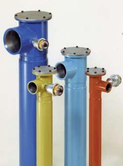
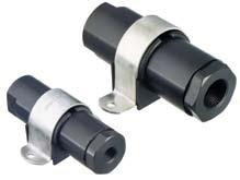

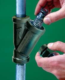
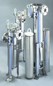
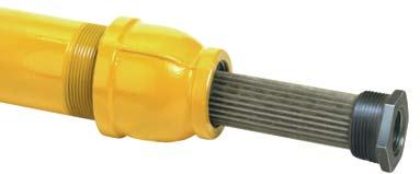
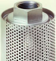
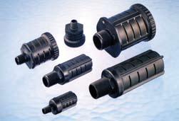
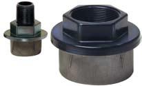
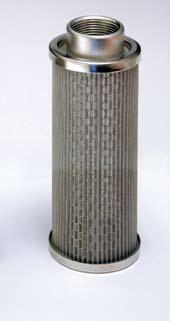
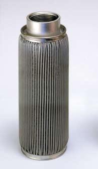
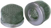
86
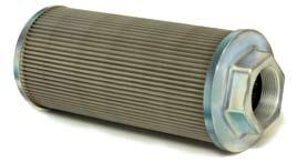
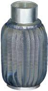
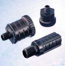


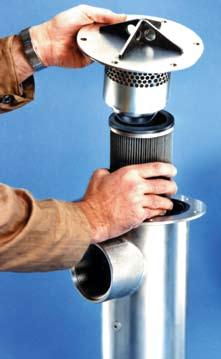
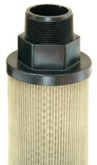
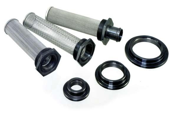
87
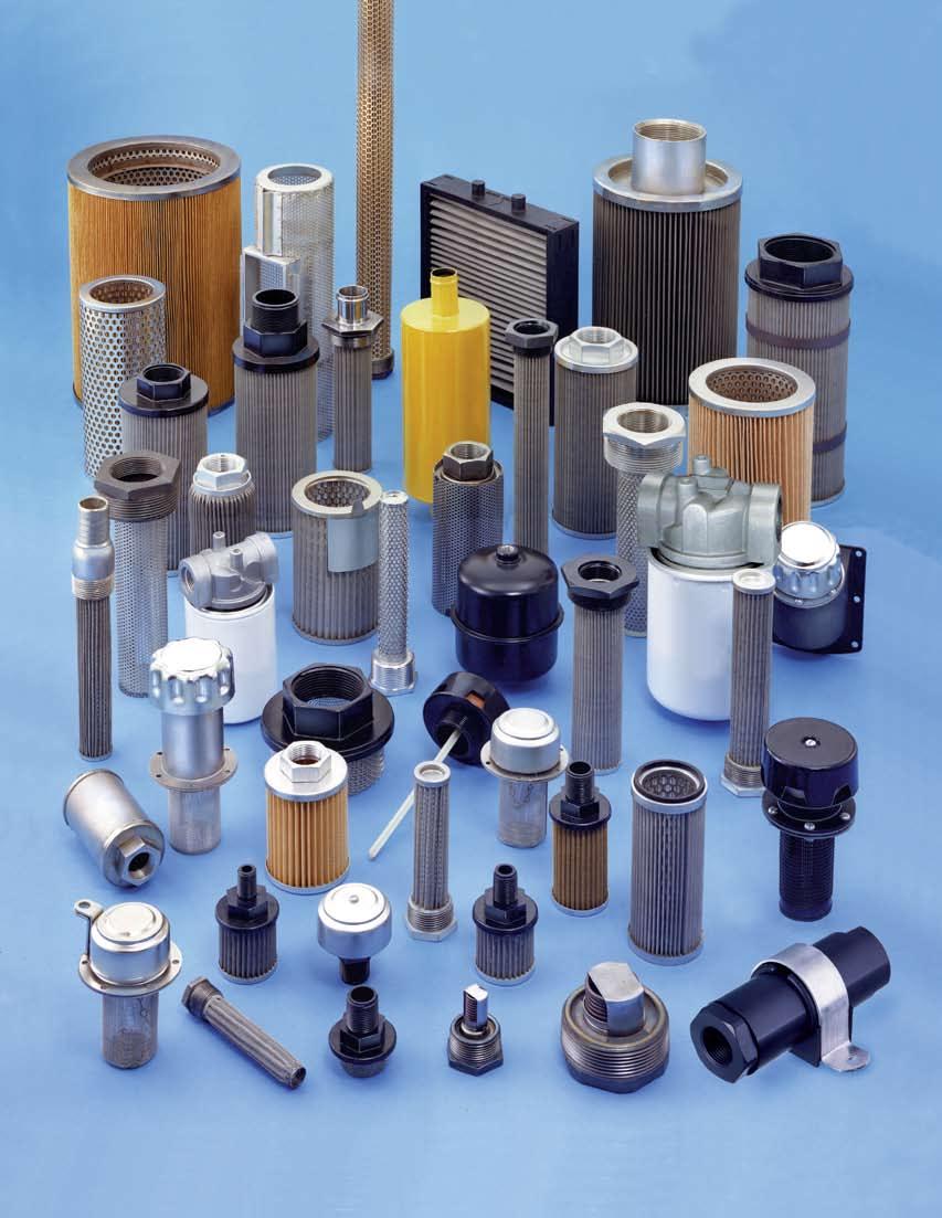
88
FILTERS, STRAINERS AND VALVES PRODUCT GUIDE
 FILTERS, STRAINERS AND VALVES PRODUCT GUIDE TEE FILTERS INLINE FILTERS BRASS FILTERS SPIN ON FILTERS OFF-LINE FILTRATION Y STRAINERS BASKET STRAINERS DUPLEX STRAINERS STRAINING ELEMENTS FRP STRAINERS DUAL
MB SERIES SMB SERIES MINIATURE TANK BREATHERS MINIATURE TANK BREATHERS ACCCESSORIES. Phone (608) Fax (608)
 Fax (608)") G1 MB SERIES MINIATURE TANK BREATHERS 10 Micron Filtration (Nominal) Shatter Resistant Plastic Construction Temperatures Up to +225 F Model A B Number Thread Size Overall Height MB-02-10 1/4 NPT 1.8 MB-03-10
G1 MB SERIES MINIATURE TANK BREATHERS 10 Micron Filtration (Nominal) Shatter Resistant Plastic Construction Temperatures Up to +225 F Model A B Number Thread Size Overall Height MB-02-10 1/4 NPT 1.8 MB-03-10
PHONE: 937/ FAX:
 Magnetic Tank Cleaners Multi Magnet Standard or Heavy Duty Lenz magnetic tank cleaners pick up material that ordinary filters miss and thus maintain cleaner oil. The cleaner the oil; the less problems
A Filtration Primer. Filter Elements. High Pressure Filters. Tank-Mounted, Return Line and Medium Pressure Filters. Water Service Filters
 A Filtration Primer Filter Elements High Pressure Filters Tank-Mounted, Return Line and Medium Pressure Filters Water Service Filters Section 6 Reservoir Accessories SCHROEDER INDUSTRIES 259 Principles
Threaded Adapters for Creating Tank Breathers. Element Attachment. Thread. O-Ring (Buna-N) Aluminum Construction. Male Pipe.
 Aluminum Construction. Male Pipe.") Reservoir Breathers Breathers are available in a variety of styles, materials and sizes. Breathers provide clean airflow into reservoirs and other storage containers where there is an exchange of air during
Reservoir Breathers Breathers are available in a variety of styles, materials and sizes. Breathers provide clean airflow into reservoirs and other storage containers where there is an exchange of air during
HIGH PERFORMANCE FILTERS INDUSTRIAL HYDRAULIC AND LUBRICATION APPLICATIONS
 HIGH PERFORMANCE FILTERS INDUSTRIAL HYDRAULIC AND LUBRICATION APPLICATIONS Microfil III media are made from micro-fine glass fibers which are randomly laid into a multilayered web. The media are impregnated
Accessories. magnaloy coupling company P.O. Box 455 Alpena, MI INDEX: Filler Breather Adapters...3
 Accessories INDEX: Magnaloy General Information... What You Should Know About Filler Breathers... Filler Breather Adapters... Filler Breathers...4 Filler Breather Cap Types...4 Mounting Flanges...4 Screen
Flow Ezy Filters. Performance Filters for Fuel and Oil Applications from
 Performance Filters for Fuel and Oil Applications from Flow Ezy Filters Flow Ezy Motorsport Filters our latest developments in motorsport technology to keep fluids clean. You can trust our 65-plus years
OVERVIEW OF RESERVOIR ACCESSORIES
 OVERVIEW OF RESERVOIR ACCESSORIES Reservoir Accessories The reservoir of a hydraulic system can be a significant source of contamination. At the same time, the reservoir is an ideal location for correcting
accessories Hydroline Filters and Accessories hydroline filters & 14 hydroline filters & accessories Filters Inline Spin on
 hydroline filters & accessories Hydroline Filters and Accessories hydroline filters & accessories Prices Sec:2 Suction Strainer Sec:4 Filters Inline Spin on Sec:5 Filter Tank Top Sec:9 Gauge Indicators
hydroline filters and accessories
 hydroline filters and accessories 12 Hydroline Filters and Accessories SECTION 12 Prices Suction Strainer Filters Inline Spin on Filter Tank Immersed Gauge Indicators Level Gauge Sight Level Gauge Threaded
Low Pressure Filters. Low Pressure Filters LOW PRESSURE FILTERS
 Low Pressure Filters Low pressure filters are the most common type of filter found in hydraulic circuits used most often in return line applications. Low Pressure Filters Donaldson low pressure filters
HIGH PRESSURE FILTERS
 HIGH PRESSURE FILTERS Series DF & LF Pressures to 6 PSI Flows to 18 GPM APPLICATION HYDAC DF & LF In-line High Pressure Filters are designed for use on hydraulic power units, machine tools, plastics machinery,
Series RFL In-Line Filter
 APPLICATION Series RFL In-Line Filter Pressures 2 bar Flows to 400 l/min HYDAC RFL In-Line Filters are designed for in-line mounting. These filters can be used in hydraulic, flushing, and for extraction
Pictorial Index Hydraulic Filters
 Hydraulic Filters Reservoir Accessories Pictorial Index Hydraulic Filters RIF-10 INLINE SPIN-ON FILTERS 1.1/4 S PAGES 356-357 PAGES 360-361 RTI AND RFI TANK TOP FILTERS PAGES 366-367 S: 1.1/4 BSPP MAX.
CUSTOM CLAMPS. Head Bolt Arrangements. Model Code B3-5 A1 B1 A1HB B1HB S1 HRSGBLPU 30 A1 373 ST
 Head Bolt Arrangements CUSTOM CLAMPS A1 B1 A1HB B1HB S1 Parts Legend 1 Hex Head Bolt 2 Socket Head Bolt 3 Steel Band 4 Band Profile 5 Swivel Sleeve 6 Hex Head Nut 7 H-Bolt 8 Locking Sleeve Series HRGBLPU
Hayward FLT Series Cartridge Filters. Features. Webster In-Tank Filtration Systems
 HAYWARD FILTERS Hayward FLT Series Cartridge Filters Designed for the most demanding applications these all plastic cartridge filters are used to filter fine particles from the process fluid. Models are
Breathers. BF...3 & BF...4 Series INNOVATIVE FLUID POWER. ø D1 HEX. Specifications. Hydraulic Symbols. Model Code. Dimensions BF P 3 G 10 W 1.0 /.
 BF...3 & BF...4 Series Maximum flow rate - 31 scfm / 230 gpm at 0.04 bar Epoxy coated steel cap Zinc-plated internals Threaded connection Pressurized breather with relief valve (optional - BF3 only) Phenolic
AUXILIARY COMPONENTS
 CHAPTER 9 AUXILIARY COMPONENTS Fluid Power Circuits and Controls, John S.Cundiff, 2001 INTRODUCTION Discussion of the hardware needed to connect the various components (pumps, actuators, valves, accumulators,
Moduflow. ILP and RFP Low Pressure Filters. Series
 Moduflow ILP and RFP Low Pressure Filters Series 27 Applications for Moduflow Filters Power Unit Fabrication Off-line Filter Loops Mobile Equipment The Moduflow filter is widely considered the most versatile
[You may download this article at: https://fluidsys.org/downloads/ ]
![[You may download this article at: https://fluidsys.org/downloads/ ]](/thumbs/79/79065708.jpg "[You may download this article at: https://fluidsys.org/downloads/ ]") Fluidsys Training Centre, Bangalore offers an extensive range of skill-based and industry-relevant courses in the field of Pneumatics and Hydraulics. For more details, please visit the website: https://fluidsys.org
Fluidsys Training Centre, Bangalore offers an extensive range of skill-based and industry-relevant courses in the field of Pneumatics and Hydraulics. For more details, please visit the website: https://fluidsys.org
Series RFLD Duplex In-Line Filter
 APPLICATION Series RFLD Duplex In-Line Filter Welded Pressures to 230 psi Flows to 3900 gpm HYDAC RFLD in-line filters are designed for in-line mounting and are mainly used in continuously operating systems.
RP-CS 2-98 CERTA-SEAL LIQUID BAG FILTERS WITH THE MATCHED PERFORMANCE DESIGN. Products
 RP-CS 2-98 CERTA-SEAL LIQUID BAG FILTERS WITH THE MATCHED PERFORMANCE DESIGN R Products INTRODUCING CERTA-SEAL LIQUID BAG FILTERS... A BETTER DESIGN RIGHT DOWN TO THE LAST NUT AND BOLT Plastic handles
TTF/BGTS Series. Return In-Tank Filters. Global Filtration Technology
 Return In-Tank Filters Global Filtration Technology 25 Features/Applications for Tank Top Return Flow Filters Flows to 640 GPM 3 Micron Absolute to 120 Micron Absolute Disposable or Recleanable Elements
Low Pressure Medium Pressure High Pressure Accessories Off-line Filtration
 Front Donaldson Cover DeliversHeadline Should HYDRAULIC Be Centered SERVICE PARTS & In ACCESSORIES This Color Box GUIDE Low Pressure Medium Pressure High Pressure Accessories Off-line Filtration Donaldson
LOW PRESSURE FILTERS RFM Series In-Tank Return Line Filters 145 psi up to 224 gpm
 LOW PRESSURE FILTERS RFM Series In-Tank Return Line Filters 145 psi up to 4 gpm Technical Specifications Mounting Method 75/9/15/165/185 mounting holes - filter housing D5 Features The compact and lightweight
SCHROEDER INDUSTRIES 335. Section 9:
 SCHROEDER INDUSTRIES 335 Section 9: Section 9 Reservoir Accessories Reservoir Accessories Page 337 SAE Weld Flanges 353 Suction Separators and Strainers 353 Oil Sight Glasses 355 Schroeder Reservoir Accessories
Oil Solutions. TTF/BGTS Series Return In-Tank Filters. Global Filtration Technology. Filtration.
 Oil Solutions Return In-Tank Filters Filtration Global Filtration Technology www.oilsolutions.com.au Features/Applications for Tank Top Return Flow Filters Flows to 640 GPM 3 Micron Absolute to 120 Micron
Index: ** Managing Machine Reliability ** How do Air Breathers work The benefits of Air Sentry Desiccant Breathers Air Sentry Z-Series Breathers
 Air Sentry Desiccant Breathers Extending fluid life saves money and downtime Index: How do Air Breathers work The benefits of Air Sentry Desiccant Breathers Air Sentry D-Series Breathers Air Sentry M-Series
Medium Pressure Filters
 Medium Pressure Filters Medium pressure filters can be used in applications up to psi (379 kpa). Donaldson offers both spin-on and in-line cartridge-style filters. Medium Pressure Filters Donaldson Duramax
LOW PRESSURE FILTERS RF Series In-tank / Inline Filters 360 psi up to 400 gpm
 LOW PRESSURE FILTERS RF Series In-tank / Inline Filters 36 psi up to 4 gpm Hydraulic Symbol A D2 Features RF 3 filters are constructed of polyamide plastic. RF 6-33 filters are constructed of aluminum
Portable Filter Carts Models 5MF and 10MF
 s Models 5MF and 10MF 161 Applications for Parker Filter Carts Filtering new fluid before putting into service Transferring fluid from drums or storage tanks to system reservoirs Conditioning fluid that
CAUTION: NOT INTENDED FOR STREET USE HOW TO USE THIS CATALOG WE LOVE RACING
 WE LOVE RACING When WIX Filters began making its performancedriven products in 1939, the first Daytona race was still 20 years down the road. In developing the WIX Racing line, WIX engineers have worked
BGT Series. Low Pressure Filters
 Low Pressure Filters 60 Applications - Flows to 640 GPM - 3 Micron Absolute to 120 Micron Absolute - Disposable or Recleanable Elements - Visual and Electrical Indicators - Microglass elements - Magnetic
HIGH PRESSURE FILTERS Series HF2P
 HIGH PRESSURE FILTERS Series HF2P Pressures to 3000 psi Flows to 25 GPM Port Size 3/4 APPLICATION HYDAC HF2 Inline High- Pressure Filters are designed for use on hydraulic power units, machine tools, plastics,
HYDRAULIC AND LUBE OIL FILTERS RFM Series
 HYDRAULIC AND LUBE OIL FILTERS RFM Series Low Pressure In-Tank Return Line Filters psi up to gpm Technical Details Mounting Method 7/9///8 mounting holes - filter housing Features The compact and lightweight
PT Series Tank Top Filters
 Tank Top Filters 9 Applications Together we can Preserve the environment. Minimize waste and promote energy efficiency. Achieve worldwide filtration solutions. Build global confidence. Redefine new limits.
HIGH PRESSURE FILTERS
 APPLICATION HIGH PRESSURE FILTERS For Manifold Block Mounting Series DF...P Pressures to 4 psi Flows to 18 gpm HYDAC DF...P High Pressure Filters are designed to be mounted directly onto the manifold block
Valves. E Valves. Multiple Hydraulic System Applications
 s Multiple Hydraulic System Applications Parker Check s are unidirectional flow control devices used primarily in hydraulic systems to eliminate potential damage caused by fluid back pressure. Offered
Portable Liquid Pump and Filter Systems Compressed Air-Powered Pump and Filter System
 Portable Liquid Pump and Filter Systems Compressed Air-Powered Pump and Filter System Technical Bulletin C PORTABLE LIQUID PUMP AND FILTER SYSTEMS DESCRIPTION Filtration Systems Portable Liquid Pump &
Model Model Model
 Filter Separators Model 9003 Model 9004 Model 9001 & 9032 Model 9002 EXAIR's Filter Separators remove water, dirt and rust from your compressed air system. They prevent these contaminants from plugging
Moduflow Series IL2/RF2/CF2 Low Pressure Filters
 IL/RF/CF Low Pressure Filters 35 Applications for Moduflow Filters Power Unit Fabrication Off-line Filter Loops Mobile Equipment The Moduflow filter is widely considered the most versatile filter available
HIGH PRESSURE FILTERS
 APPLICATION HIGH PRESSURE FILTERS For Manifold Block Side Mounting Series DF...QE Pressures to 4 psi Flows to 18 gpm HYDAC DF...QE High Pressure Filters are designed to be side mounted directly onto the
Filter Cart. hyprofiltration.com/fc
 Filter Cart A fully self-contained mobile solution for bulk oil handling, fluid transfer and reservoir or gearbox conditioning. Ideal for lower viscosity hydraulic oil, lube oil and diesel fuel. Engineered
Rosedale Model HSS300 and HSS750 Single Cartridge Housings for Liquids
 H S S S I N G L E C A R T R I D G E H O U S I N G S Rosedale Model HSS0 and HSS750 Single Cartridge Housings for Liquids Precision Machined Knife-Edge Seal The Rosedale Model HSS single element filter
15/40/80CN Series. Medium Pressure Filters
 //8CN Series Medium Pressure Filters 7 //8CN Series Applications for CN series Filters Compressor Lube Oil Off-line Filter Loops Machine Tools (Automotive Standard) Hydrostatic Drive Charge Pumps Mobile
MINING FORESTRY MOBILE TRUCK AGRICULTURE MATERIAL HANDLING OPTIMUM
 MINING FORESTRY MOBILE TRUCK AGRICULTURE MATERIAL HANDLING OPTIMUM Muncie Power Products OPTIMUM Series gear pumps/motors offer premier performance for a wide variety of applications across several industries.
Oil Solutions. GA/BGAH Series Medium Pressure Filters. Global Filtration Technology. Filtration.
 Oil Solutions Medium Pressure Filters Filtration Global Filtration Technology www.oilsolutions.com.au Features/Applications for Medium Pressure Inline Filters GA Series Pressures to 750 PSI Flows to 100
Dynaswivel. Air Line Connectors. Ball-Swivel Plug. Never Fight an Air Tool Again! For Use with Most Air Tools THE PROBLEM THE SOLUTION
 Dynaswivel Air Connectors Never Fight an Air Tool Again! For Use with Most Air Tools THE PROBLEM Aluminum and Stainless Steel Construction Single Pivot Right angle single-pivot swivels 360 at one location.
Engine Liquid Filtration
 Engine Liquid Filtration Lube/Oil, Fuel, Coolant, Hydraulic and Transmission Since 1915, we have delivered innovative filtration solutions that protect engine components to extend the life of your equipment.
12AT/50AT Series Spin-On Filters
 1 Applications for Mobile Equipment Hydrostatic Drives Industrial Power Units Reservoir Breathers Often, economic conditions dictate what type of filter is used on a piece of equipment. When costs are
AIR PREPARATION PRODUCTS. Table of Contents
 AIR PREPARATION PRODUCTS Table of Contents Page Air Filters................................................. 5-7 Oil Removal Filters......................................... 8-9 Regulators..............................................
Medium Pressure Filters
 Medium Pressure Filters Medium pressure filters can be used in applications up to 2 psi (1379 kpa). Donaldson offers both spin-on and in-line cartridge-style filters. Medium Pressure Filters MEDIUM PRESSURE
Fixed Displacement Gear Pumps
 Fixed Displacement Gear Pumps D/H/HD Series Introduction Series D/H/HD Features Pressure-loaded design Efficient, simple design - few moving parts Exceptionally compact and lightweight for their capacity
For Residential and Light Commercial Applications
 For Residential and Light Commercial Applications ES-WQ-PWPleatedFilter Job Name Contractor Job Location Approval Engineer Contractor s P.O. No. Approval Representative Series PWFIL-SED-PLT Pleated Filter
LUBRICATION & FLUID HANDLING ACCESSORIES. Heavy duty knurled steel barrel with large threads for easy loading.
 hand grease guns Lever type The tough high pressure cast iron head makes Pro-Master Grease Guns unique in comparison to common pot metal or other die cast heads with a head burst pressure of 17,000 PSI
Liquid Strainers. Protect nozzles, valves and pumps from damaging debris. Experts in Spray Technology Spray Nozzles. Spray Fabrication.
 Experts in Technology Nozzles Control Analysis Fabrication Liquid Strainers Protect nozzles, valves and pumps from damaging debris. Table of Contents T Strainers Low to Medium Pressure TW...3 TWC...3 TWF...4
WELCOME. Give us a call.
 Filter Catalog WELCOME The Facility Maintenance Solutions Company Welcome to Tri-Chem Corporation. For over 40 years we have been helping organizations, just like yours, with their toughest facility maintenance
Fluid Power Accessories
 Fred C. Gilbert Co. 106 Norris Road Bakersfield, Ca. 93308 661-399-9569 fax 661-393-9654 PNEUMATIC EXHAUST MUFFLERS Breather Vents 2,3 Exhaust Mufflers 2-5 Reclassifiers / Mufflers 6,7 BREATHER VENTS Speed
Custom & Standard Filter Elements ISO 9001:2008 CERTIFIED
 Custom & Standard Filter Elements ISO 9001:2008 CERTIFIED What Makes It a Swift Filter Enthusiastically accepts custom element projects Has ability to do special machining Will entertain short-run projects
Duplex Pressure Filters
 Duplex Pressure Filters Series DFDK Ball Valve Selector Pressures to 45 psi Flows to 9 gpm APPLICATIONS HYDAC DFDK Duplex Filters are ideal for use on hydraulic test equipment, robots, or other critical
HY-PRO FILTRATION. FSL Filter Unit Flow rate up to 22 gpm (83 lpm)
") FSL HY-PRO FILTRATION Materials of Construction Assembly Frame: Painted Steel Drip Pan: Painted Steel Filter Assembly: Epoxy coated steel 25 or 50 psid bypass available True differential pressure indicator
FSL HY-PRO FILTRATION Materials of Construction Assembly Frame: Painted Steel Drip Pan: Painted Steel Filter Assembly: Epoxy coated steel 25 or 50 psid bypass available True differential pressure indicator
North American Y-Type Strainers for Gas, Oil, Oxygen, Steam
 Combustion North American Y-Type s for Gas, Oil, Oxygen, Steam The new 8555Y line provides many unique features: High pressure and temperature designs for rugged industrial applications Body and screen
Low Profile J Series Power Unit with Vane Pump
 Low Profile J Series Power Unit with Vane Pump READ ALL INSTRUCTIONS CAREFULLY BEFORE ATTEMPTING TO ASSEMBLE, INSTALL, OPERATE OR MAINTAIN THE PRODUCT DESCRIBED. PROTECT YOURSELF AND OTHERS BY OBSERVING
NFH Low Pressure Filters
 PPLICTIONS NFH Low Pressure Filters Pressures to 360 psi Flows to 450 gpm Water Removal Capability 4 Ports HYDC NFH In-line Return Filters are designed for use on hydraulic power units, machine tools,
15/40/80CN Series Coreless Medium Pressure Filters
 //8CN Series Coreless Medium Pressure Filters 89 //8CN Series Applications Compressor Lube Oil Off-line Filter Loops Machine Tools (Automotive Standard) Hydrostatic Drive Charge Pumps Mobile Equipment
MEDIUM PRESSURE FILTERS
 Medium Pressure Filters 61-2999 psi Low-cost aluminum construction inline filters, provide flexibility for use in both mobile and industrial applications. Durable and light weight, these filters are ideal
Pneumatic High-Viscosity Filtration System Instruction Manual
 Pneumatic High-Viscosity Filtration System Instruction Manual P/N: 61512 05/17 1 2 Pneumatic High Viscosity Filtration Systems PN: 61512 14 April, 2009 rev A 36933 Pneumatic Hand Cart HV Filtration System
Glass-Filled Nylon and Metal Breathers IP65 Rated, Metal, Screw-on and Lockables Reservoir Equipment
 Glass-Filled Nylon and Metal Breathers IP65 Rated, Metal, Screw-on and Lockables Compact and lightweight reservoir solutions IP65 Co-polymer breathers and metal breathers The IP65 rated range of moulded,
Cartridge Filter Housings Nowata A Series
 Cartridge Filter Housings Nowata A Series Customization May Change the Model Number Designation to B, D or F Series 1. Introduction All A series cartridge filter housings are designed for efficient liquid
FOR AIR CONDITIONING AND VENTILATING APPLCATIONS
 PANELS FOR AIR CONDITIONING AND VENTILATING APPLCATIONS KLEENFLO for your average filter problem A permanent, all-metal, cleanable, viscous-impingement filter, the KLEENFLO provides excellent efficiency
12AT/50AT Series. Spin-On Filters. Global Filtration Technology
 1AT/5AT Series Spin-On Filters Global Filtration Technology 1 1AT/5AT Series Applications for Spin-On Filters n Mobile Equipment n Hydrostatic Drives n Industrial Power Units n Reservoir Breathers Often,
BRASS FITTINGS and Related Products
 Discount Hydraulic Hose.com Cat. BR602 February, 2006 Prices Subject to change BRASS FITTINGS and Related Products Air Brake Fittings: Nylon Tubing 2 Push-In Air Brake Fittings 4 Pre-Assembled Air Brake
HYDROSTATIC TEST SYSTEM MANUAL
 PDQC HYDROSTATIC TEST SYSTEM MANUAL Technical Specification Operating Instructions Part List Revised 12-2016 Manual # PDQC- 6,000 And PDQC-10,000 1 PDQC PERFORMANCE DATA Model Number Maximum Pressure Volume
TABLE OF CONTENTS. Accessories. Filler Breather 7 Filler Heads 11 Foot Brackets 6 J. Jaw Couplings 9 Jaw Couplings - Dimensions/HP ratings 8 S
 accessor i es TABLE OF CONTENTS Accessories F Filler Breather 7 Filler Heads 11 Foot Brackets 6 J Jaw Couplings 9 Jaw Couplings - Dimensions/HP ratings 8 S Strainers 12 Stroke Limiter 3 Subplates 10 BORE
12CS Series. Coreless Spin-on Filter Max. 75 l/min - 35 bar. Environmentally friendly alternative for spin-in filtration.
 12CS Series Coreless Spin-on Filter Max. 7 l/min - 3 bar Environmentally friendly alternative for spin-in filtration Lightweight, non-metallic element that can be incinerated The 12CS Series features a
ATMOSPHERIC PRESSURE RATINGS ATMOSPHERIC PRESSURE RATINGS
 FEET OF WATER TO INCHES OF MERCURY (BASED AT SEA LEVEL) FT. OF WATER IN. OF MERCURY FT. OF WATER IN. OF MERCURY 1 0.9 18 15.9 2 1.8 20 17.7 4 3.5 22 19.4 6 5.3 24 21.2 8 7.1 26 23.0 10 8.8 28 24.8 12 10.6
Lubrication Installation Components, Accessories & Fittings Table of Contents
 Lubrication Installation Components, Accessories & Fittings Table of Contents Lubrication Fittings & Accessories: Introduction............................................. 2 Threaded Fittings........................................
SPIN-ON FILTERS & ELEMENTS
 ABSOLUTE RATED (BETA SPIN ) & NOMINAL RATED SPIN-ON FILTERS & ELEMENTS Single and Twin Element Models Pressures to 20 psi Flows to 120 gpm APPLICATION HYDAC Spin-On Filters are for filtration of hydraulic
Pressure Sensor No Series
 Sales Manual Section 335 PRODUCT SPECIFICATION 84372 SERIES Pressure Sensor No. 84372-Series GENERAL DESCRIPTION The patented* No. 84372-Series Pressure Sensor contains a weatherproof, snap-acting valve
FCL Filter Cart Flow rate up to 22 gpm (82 lpm)
") click here to return to website FCL Filter Cart Flow rate up to 22 gpm (82 lpm) Ideal for high viscosity Lubrication and hydraulic oils (ISOVG22 ~ ISOVG320) Filter new fluids during transfer and replenishment
click here to return to website FCL Filter Cart Flow rate up to 22 gpm (82 lpm) Ideal for high viscosity Lubrication and hydraulic oils (ISOVG22 ~ ISOVG320) Filter new fluids during transfer and replenishment
Courtesy of CMA/Flodyne/Hydradyne Motion Control Hydraulic Pneumatic Electrical Mechanical (800)
") Features MF Filters are manufactured with an aluminum head. MF, MFD, MFDS Series Spin-On Filters Choice of NPT, SAE straight thread O-ring boss, BSPP, and SAE 4-bolt flange porting to allow easy installation
Features MF Filters are manufactured with an aluminum head. MF, MFD, MFDS Series Spin-On Filters Choice of NPT, SAE straight thread O-ring boss, BSPP, and SAE 4-bolt flange porting to allow easy installation
Automizer Combination Control Valves
 Combination Control Valves Recommended Applications Where actuated valves and balancing valves are used to control the flow For VAV boxes, fan coil units and terminal boxes Where space is tight Absolute
FLUID POWER GROUP PRODUCT CATALOG / MARADYNE.COM
 FLUID POWER GROUP PRODUCT CATALOG 800-537-7444 / MARADYNE.COM CAPABILITIES Filter Manufacturing Assembly Complex Manufacturing Injection & Roto Molding Electric Motors & Fans ISO 5011 Air Filter Lab PRODUCTS
Low Pressure Filters
 MF, MFD, MFDS Series Spin-On Filters 250 PSI up to 120 GPM Hydraulic Symbol /80/85/160/180 MF 90/95/190/195 A A B B Features MF Filters are manufactured with an aluminum head. Choice of NPT, SAE straight
MOISTURE MEETS ITS MATCH
 Donaldson Delivers T.R.A.P. Breather Technology For Hydraulic and Lube Oil Reservoirs MOISTURE MEETS ITS MATCH Donaldson T.R.A.P. breathers collect and expel the moisture out of reservoirs, which means
Top Side Door Door Model Work Area Height Door Options Opening Opening Gun Options Weight
 FLOOR MODEL STEEL CABINETS 40403 40413 Standard Features for All Models 100 CFM dust collector included with all steel cabinets HD 14 gauge steel - welded seams Full width top door Optional additional
Oil Conditioning Unit
 66 Applications The Parker Oil Conditioning Units (OCU) are a family of off-line filtration packages designed to effectively remove water or particulate contamination from hydraulic and lube system fluids.
LECTURE 30 to 31 ACCESSORIES USED IN FLUID POWER SYSTEMS FREQUENTLY ASKED QUESTIONS
 LECTURE 30 to 31 ACCESSORIES USED IN FLUID POWER SYSTEMS FREQUENTLY ASKED QUESTIONS 1. Explain the two types of the leakages in hydraulic system. In what way do they affect the performance of a fluid system?
F SERIES GEAR PUMP. 2 Muncie Power Products, Inc Muncie Power Products, Inc.
 ALL NEW DESIGN F SERIES GEAR PUMP ALL NEW DESIGN Ultimate power and performance in a small package best describes the all new F Series gear pumps. Designed exclusively for those low flow applications.
Marine Turbine Series
 1000MA Water-in-fuel sensor and indicator. All Racor filter materials and seals are compatible with ultra-low sulphur diesel (ULSD) fuel and B2 to B20 Biodiesel. See Racor bulletin 7679. The complete Primer
Marine Fuel Filtration. Marine Turbine Series. Stage One: Separation. Stage Two: Coalescing. Stage Three: Filtration. And more
 filter assemblies are designed to be installed on the vacuum side of the fuel transfer pump for best efficiency and protect precision engine components from dirt, rust, algae, asphaltines, varnishes, and
IL8 Series. Medium Pressure Filters
 Medium Pressure Filters 6 Applications for IL8 series filters Lube oil systems Power generation plants Test stands Primary metal equipment Pulp & paper equipment Offshore drilling and oil patch Flushing
AGS/MPN Series. Medium Pressure Filters. Global Filtration Technology
 Medium Pressure Filters Global Filtration Technology 63 Features/Applications for Medium Pressure Inline Filters AGS Series Rated Working Pressure 1000 PSI Rated Static Pressure 1500 PSI Flows to 25 GPM
IL8 Series. Medium Pressure Filters
 Medium Pressure Filters Applications for IL8 series filters Lube oil systems Power generation plants Test stands Primary metal equipment Pulp & paper equipment Offshore drilling and oil patch Flushing
Industrial Turbo Meters, Sizes 2" through 6"
 Industrial Turbo Meters Sizes 2" through 6" TUR-UM-00530-EN-19 (October 2014) User Manual Industrial Turbo Meters, Sizes 2" through 6" User Manual CONTENTS Scope of the Manual 5 Specifications 5 Product
Easy to assemble Available with long or short nut in wide range of styles and sizes 651 MALE ELBOW 5/16 O.D. TUBE 1/8 PIPE MALE CONNECTOR
 A29-1 TM CIC 200 BRASS COMPRESSION TUBE FITTINGS ASSORTMENT P/N 7745 Medium pressure air, oil, water and natural gas applications Manufactured from high density brass alloy No flaring or soldering required
HIGH PRESSURE FILTERS
 APPLICATION HIGH PRESSURE FILTERS For Manifold Block Mounting Series DF...P Pressures to 45 psi Flows to 18 gpm HYDAC DF...P High Pressure Filters are designed to be mounted directly onto the manifold
Model Model Model 3650 Model 3614
 Model 3601 Model 3662 Model 3650 Model 3614 Model 3675 Portable used fluid handling equipment and fuel caddies Collection equipment pressurized (self-evacuating)....... 170 Upright drains.....................................
JAN ULTIMA GEAR OIL ULTIMA ENGINE OILS. Ultima Racing 20W50 Full Synthetic. Premium 80W90 Gear Oil. Ultima Premium Blend. 20W50 Synthetic Blend
 JAN 18 ULTIMA GEAR OIL -25 Premium 80W90 Gear Oil ULTIMA ENGINE OILS ULTIMA PREMIUM BLEND STRAIGHT WEIGHT ENGINE OILS High Zinc additive resists wear and provides exceptional load carrying characteristics