WHEEL LOSS. A Risk No One Can Run!
|
|
|
- Arline Williams
- 6 years ago
- Views:
Transcription


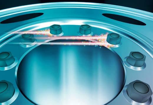


1 WHEEL LOSS A Risk No One Can Run!
2 Legal deposit Bibliothèque et Archives nationales du Québec, 3rd quarter 2017 ISBN (PDF version) Société de l assurance automobile du Québec, 2017 Original text in French.
3 Foreword This manual is intended to raise the awareness of heavy vehicle owners, professional wheel installers, drivers and maintenance staff about the importance of proper wheel installation and securing for safe travel. This is not a text of law. For any questions of a legal nature, please refer to the Highway Safety Code and attendant regulations. The information contained in this manual is provided for reference purposes only and does not bind the Société de l assurance automobile du Québec (SAAQ). Reproduction in whole or in part of this manual is authorized, provided the source is indicated. Please send your comments and suggestions concerning this manual to: Direction de l expertise et de la sécurité des véhicules Société de l assurance automobile du Québec Case postale 19600, succursale Terminus 333, boulevard Jean-Lesage, E-4-34 Québec (Québec) G1K 8J6 1
4 2
5 Table of Contents Introduction 5 1 RESPONSIBILITIES 7 2 general principles 9 3 the safe way to change a wheel on a heavy VEHICLE Preparation Verification Mounting 13 4 Stud-piloted disc wheels with ball seat mounting Verification Torquing 16 5 hub-piloted disc wheels Verification Torquing 22 6 SPoke wheels Verification Torquing Rim alignment check Correction of excessive rim deviation 30 7 TIGHTENING ON THE ROAD 31 8 thoughts ON THE SUBJECT of WHEEL BEarINGS 33 EngLISH-FREnch GLOSSary 35 Bibliography 36 3
6 4
7 Introduction Wheel Loss: A Risk No One Can Run! Having wheels come off a vehicle is generally caused by poor assembly, badly adjusted or improperly lubricated bearings, or the result of inadequate maintenance or inspection. This manual summarizes safe practices for the installation and proper maintenance of stud-piloted disc wheels with ball seat mounting, hub-piloted disc wheels and spoke wheels. It gives specific advice on securing wheels, safety rules and tightening procedures to keep the wheels in place, based on the type of mounting system and type of wheel used. 5
8 6
9 1 responsibilities Taking preventive action is the only way to avoid wheels coming off a vehicle. The vehicle owner, the professional wheel installer, the driver or the person designated by the operator to perform the circle check and the person in charge of the preventive maintenance check all have a preventative role to play: The owner must make sure that the person who installs the wheels or maintains the wheel bearings on his or her vehicle has the skills and know-how to do that type of work. The professional installer, by reason of his or her skills in the field, must strictly observe installation standards and keep abreast of the latest developments so that the vehicle will be safe for both the driver and the other road users. The driver or the person designated by the operator is responsible for having performed a circle check and filling out a circle check report, as specified in the Regulation respecting safety standards for road vehicles, within the previous 24 hours. During the trip, e.g. before getting back on the road after a rest or a stop at a restaurant, the driver is also responsible for carrying out the necessary verifications in order to keep the circle check report up to date. The driver is the person closest to the vehicle and is responsible for ensuring his or her own safety as well as the safety of others. Any anomalies detected regarding the wheels or bearings must be noted and repaired before getting back on the road or continuing the trip. The person in charge of preventive maintenance must ensure that the carrier s preventive maintenance program contains a section on the installation, inspection, maintenance and repair of wheels and bearings. 7
10 8
11 2 General principles Each person in charge must, if applicable: Preferably use a torque wrench to tighten the nuts to the recommended torque level OR use an impact wrench equipped with a torque stick, the length of which corresponds to the wheel manufacturer s recommended torque level. When using an impact wrench that is not fitted with a torque stick to tighten the nuts, make sure it is properly adjusted so that the torque values will be within the recommended limits. Nut tightening must be finished off with a torque wrench. Too much torque (creep*) can be as dangerous as too little. Calibrate torque wrenches at least once a year. Some brands of torque wrenches have not been calibrated by the manufacturer prior to purchase; these must be calibrated before use. Be attentive to the fact that when a reconditioned disc wheel is used, the layers of protective paint can amount to mm (0.012 in) thick. When the drum heats up, this paint disappears, resulting in loosening of the wheel. All traces of paint must be removed from the contact surfaces prior to tightening. Wheels must be reconditioned according to the manufacturer s specifications. Check the torque level on wheels after the first 80 to 160 km of use following installation. * Creep: Deformation of a metal subjected to very heavy loads. 9
12 Keep the wheels clean so as to more easily detect cracks, oil leaks, loose nuts or any other damage. Be attentive to the slightest oil leak, which points to a damaged hub ring seal or that a wheel bearing is about to slip out of its cup. Do not hesitate to raise a suspect wheel to examine the bearings. If the lubricant is leaking, this situation must be corrected as quickly as possible. Check the wheels as soon as possible after an unusual manoeuvre, such as sudden braking, to make sure no nut, stud or wheel has been damaged. Wheels can be loosened in a sharp turn involving contact with a curb or the edge of a sidewalk. In such cases, the wheels in question must be inspected immediately. 10
13 3 THE SafE WAY to CHANGE A WHEEL on A HEavy VEHICLE Points marked with a star are required only when a wheel is changed on the road. Points marked with an X apply only to a spoke wheel. 3.1 Preparation The driver must: 1. Bring the vehicle to a stop at a safe place (rest stop, garage) on a solid, horizontal surface capable of supporting the weight of the load. 2. Apply the parking brake. 3. Make sure the transmission is in first gear. 4. Switch on the hazard lights. 5. Establish a safety perimeter by using reflective devices or other emergency equipment specified in the Regulation respecting safety standards for road vehicles as follows: on a road with two-way traffic, the reflective devices or other emergency equipment must be placed on the traffic side of the roadway: the first two at 3 m and 30 m behind the vehicle, and a third at 30 m ahead of the vehicle; on a divided highway, the reflective devices must be placed on the roadway, 3, 30 and 60 m behind the vehicle (facing oncoming traffic). 6. Place chocks under the wheels. 7. Install the jack at the recommended location. 11
14 8. Loosen the nuts by 1/2 to no more than 1 turn. 9. Jack up the vehicle so that the tire on the wheel to be replaced no longer touches the roadway. 10. Loosen the nuts without removing them (risk of rim clamps flying off). 11. Use a hammer to dislodge the rim clamps. 12. Remove the nuts: the rim clamps. 13. Remove the outside wheel: the rim spacer (if necessary); the inner wheel (if necessary). 3.2 Verification For stud-piloted disc wheels, see Section 4.1. For hub-piloted disc wheels, see Section 5.1. For spoke wheels, see Section
15 3.3 Mounting The driver must: 1. Place the inner wheel back in the same location as prior to removal, if possible. 2. Make sure the valve stem is properly centred. 3. Reinstall the spacer between the wheels (dual assembly). 4. Reinstall the outer wheel and centre the valve (dual assembly). 5. Tighten the nuts slightly (preliminary tightening to around 67.8 Nm (50 ft-lb). 6. Make sure the wheel chocks are in place and the transmission is in first gear. 7. Tighten the nuts according to the procedure described in Section Release the parking brake. 9. Tighten the wheels according to the procedure described in Sections 4.2 and Check the wheel alignment according to the procedure described in Section Apply the parking brake. 12. Lower the wheel to the ground and check the final torque. 13. Remove the jack, the chocks and the reflectors. 14. Check the nuts again after travelling between 80 and 160 kilometres. 13
16 14
.")
17 4 STUD-PILotED DISC WHEELS WIth BALL SEat MOUNTING Wheel Ball seat cap nut Hub 4.1 Verification N. B. Follow the wheel manufacturer s instructions if they are different from the instructions provided below. You must: Make sure the contact surfaces between the wheel and the drum are clean before mounting a wheel. Check the stud holes for cracks or wear (oval-shaped holes). Check both sides of the disc to make sure there is no crack or warp. Inspect the entire wheel to make sure there is no crack, gouge or air leak. Make sure the threads on the studs and nuts are clean and free of any defects. 15
18 Check for any signs of rust or dirt around a nut, which usually indicates it has become loosened. Important: Installing a stud-piloted wheel on a hub-piloted assembly or vice versa can be dangerous. 4.2 Torquing Ball Seat Cap Nuts Diameter Number of Threads Recommended Dry Torque Level Standard 22 mm (7/8 in) 19 or 29 mm (3/4 in or 1 1/8 in) 16/in 610 to 678 Nm (450 to 500 ft-lb) Important (aluminum wheels only): If a thread lubricant is used, reduce torque to 475 to 542 Nm (350 to 400 ft-lb). Remember: For this type of mounting, the threads are right-handed on the right side of the vehicle and left-handed on the left side of the vehicle. The stud standout should be stamped L for LEFT and R for RIGHT. 16
 to a torque level of 67.8 Nm (50 ft-lb) using the proper sequence (Illustration 3). 2. Tighten the nuts gradually to the recommended torque level. 3. Tighten the outer nut (Illustration 2) to a torque level of 67.")
19 N.B.: This type of mounting requires an inner cap nut to centre and hold the inner wheel on a dual assembly and a ball seated cap nut to secure the outer wheel (Illustrations 1 and 2). You must: 1. Tighten the inner cap nut (Illustration 1) to a torque level of 67.8 Nm (50 ft-lb) using the proper sequence (Illustration 3). 2. Tighten the nuts gradually to the recommended torque level. 3. Tighten the outer nut (Illustration 2) to a torque level of 67.8 Nm (50 ft-lb) using the proper sequence (Illustration 3). 4. Tighten the nuts gradually to the recommended torque level. Illustration 1 Inner cap nut Illustration 2 Outer cap nut 17

20 Illustration 3 Torque sequence for wheel with 6 or 10 studs Do not apply any lubricant to the cap nut, the contact surface of the nut or the threads. Lubricated surfaces can result in excessive tightening, which causes stretching and rupture of the studs. Nuts that are not tightened to the correct torque cause the wheels to loosen, premature wear or damage to the ball seats and the wheels coming off. Studs Hub Drum Inner wheel Illustration 4 Studs and nuts 18
. N. B.")
21 Important: On a dual stud-piloted wheel assembly, the outer wheel nuts must be loosened slightly and the inner wheel tightened to the recommended torque level. Then, tighten the outer wheel following the proper torque sequence (Illustration 3). N. B.: When changing a stud on a 10-stud assembly (Illustration 4) is required, adjacent studs must also be replaced. In cases where the assembly has fewer than 10 studs, all of them must be replaced at once since the remainder have been subjected to greater stress by bearing the entire load and could be in a state of extreme metal fatigue (creep*). * Creep: Deformation of a metal subjected to very heavy loads. Disc Outer wheel Nuts 19
22 20
23 5 HUB-PILotED DISC WHEELS Wheel Nut Hub 5.1 Verification N. B.: Follow the wheel manufacturer s instructions if they are different from the instructions provided below. For all of the parts, you must: Make sure the contact surfaces between the wheel and the drum are clean before mounting a wheel. Check the stud holes for cracks or wear (oval-shaped holes). Check both sides of the disc to make sure there is no crack or warp. Inspect the entire wheel to make sure there is no crack, gouge or air leak. 21
24 Make sure the threads on the studs and nuts are clean and free of any defects. Check for any signs of rust or dirt around a nut, which usually indicates it has become loosened. Remember: Installing a hub-piloted wheel on a stud-piloted assembly or vice versa can be dangerous. 5.2 Torquing Wrench Size Diameter Number of Threads Recommended Dry Torque Level 33 mm (1 1/2 in) M to 678 Nm (450 to 500 ft-lb) Important (aluminum wheels only): If a thread lubricant is used, reduce torque to 475 to 542 Nm (350 to 400 ft-lb) Illustration 5 Torque sequence for wheel with 8 or 10 studs 22

25 You must: 1. Use a torque wrench to tighten the nuts evenly in the proper sequence (Illustration 5). 2. Tighten the nuts to a torque level of 67.8 Nm (50 ft-lb). 3. Tighten the nuts gradually to the recommended torque level. Note: All threads are right-handed. Flange Lubricate here Nut Illustration 6 Two-piece flange nut 4. Lubricate with a few drops of oil where indicated on the type of nut shown in Illustration 6. 23
26 N.B.: When changing a stud on a 10-stud assembly (Illustration 4) is required, adjacent studs must also be replaced. In cases where the assembly has fewer than 10 studs, all of them must be replaced at once since the remainder have been subjected to greater stress by bearing the entire load and could be in a state of extreme metal fatigue (creep*). * Creep: Deformation of a metal subjected to very heavy loads. 24
 (Illustration 7); burr or foreign body (file smooth if necessary). 2.")
27 6 SPOKE WHEELS 6.1 Verification N. B.: Follow the wheel manufacturer s instructions if they are different from the instructions provided below. For all of the parts, you must: 1. Examine the rim mounting surfaces to make sure there is no: dirt or foreign body; defect or wear pattern (wheel slippage or other) (Illustration 7); burr or foreign body (file smooth if necessary). 2. Check for cracked or broken spokes. 3. Replace the rim spacer if it is crushed, dented or broken. 4. Make sure the threads (studs and nuts) are clean and free of any defects. 5. Examine the rim clamps to make sure they are in good condition. 6. Make sure the valve locators are in the proper position and in good condition (Illustration 7). 25
 19 mm (3/4 in) Number of Threads 11/in 10/in Recommended Dry Torque Level 217 to 271 Nm (160 to 200 ft-lb) 271 to 353 Nm (200 to 260 ft-lb)")
28 Valve locators Slippage Illustration 7 Valve locators and slippage 6.2 Torquing Diameter 16 mm (5/8 in) 19 mm (3/4 in) Number of Threads 11/in 10/in Recommended Dry Torque Level 217 to 271 Nm (160 to 200 ft-lb) 271 to 353 Nm (200 to 260 ft-lb) You must use a torque wrench and tighten the rim clamps evenly in the proper sequence (Illustration 8). 26
.")
29 Illustration 8 Torque sequences 5 2 Rims Nut Clamp Flange Rim spacer Wheel Flange Illustration 9 Clamp and rim spacer Important: Do not tighten the rim clamps excessively. Overtorquing can deform the rim spacer and damage the back flange (Illustration 9). 27
30 Heelless rim clamps: when a heelless rim clamp is tightened to the specified torque level, it must not touch the spoke (Illustration 10a). Clamp Heelless Gap Wheel spoke Illustration 10a Heelless rim clamps Heel-type clamps: when the heel of clamp comes into contact with the spoke (Illustration 10b), you must have reached 80% of the maximum specified torque level. Note that a gap of 6.3 mm (1/4 in) between the heel and the spoke is acceptable but not mandatory. If the gap is greater than 6.3 mm (1/4 in) after the recommended maximum torque level is reached, check to make sure you are using the correct spacer or rim clamp. 28


31 Clamp Heel Illustration 10b Heel-type clamps Wheel spoke 6.3 Rim alignment check Clamp Block of wood Chalk Rim Illustration 11 Installation for rim alignment check 29
32 Proceed as follows: Place a block of wood at 12 mm (1/2 in) from the tire; Rotate the wheel slowly to check for and measure any deviation; Correct any deviation over 1.6 mm (1/16 in) on a front wheel and 3 mm (1/8 in) on a rear wheel. 6.4 Correction of excessive rim deviation You must: Rotate the wheel slowly and bring the chalk close to the tire (Illustration 11). When the chalk leaves a mark on the tire, this indicates the maximum deviation. Slightly loosen the nuts opposite the reference mark left by the chalk. Tighten the nuts facing this reference mark as well as the adjacent nuts without exceeding the maximum torque level. Check for deviation again. If there has been no change, look for deformed, crushed or broken parts, or any other defect. Tighten and repeat the operation if necessary. Note: Deviation that is difficult to correct could point to a damaged component, in which case the entire assembly must be checked again. 30
33 7 TIGHTENING on THE ROAD Tightening wheels without the use of a torque wrench is considered a temporary solution, which should be repeated every 80 to 160 km of use, until the wheels can be properly tightened with a torque wrench according to the method indicated on page 11. A good habit to get into is to ask the person torquing the wheels on your vehicle to write down the torque level on the invoice as well as the date on which the wrench was last calibrated. 31
34 32
35 8 THOUGHTS ON THE SUBJECT of WHEEL BEarINGS * According to the results of an investigation ordered in September 1995 by the State of Maryland, the lack of proper lubrication for wheel bearings was among the main causes of wheel loss accidents. What occurs is that the bearings overheat due to a lack of lubricant. Without proper lubrication, tiny pieces of metal wear off the bearings and fall into the lubricating fluid and serve as a grinding compound for the bearing mechanism. Once the mechanism is weakened, the lack of support for the hub/wheel/drum assembly eventually results in wheel separation. There can be no doubt: drivers and maintenance personnel must pay more attention to the inspection and maintenance of wheel assemblies. At what intervals must bearings be replaced when grease is used? At what intervals should the lubricant level be checked if oil is used? At what intervals must the wheels be raised and rotated to check for noise (cracked bearings) or excessive play (improperly adjusted bearings)? Has the driver been shown how to check the hub temperature when they inspect the tires on the vehicle as part of the circle check? If not, you should do so. Happy trails! * See the brochure titled Wheel Loss Due to Faulty Bearings, available on the SAAQ website at saaq.gouv.qc.ca. 33
36 34
37 EngLISH-FREnch GLOSSary back flange: embase arrière ball seat cap nut: écrou conique buckle: voile clamp: crapaud (étrier) drum: tambour dual wheel: roue jumelée hub: moyeu impact wrench: outil pneumatique à percussion inner cap nut: écrou interne nut: écrou oil seal: joint d étanchéité outer cap nut: écrou externe parking brake: frein de stationnement rim spacer: entretoise spoke wheel: roue moulée stud: goujon thread: filet torque sequence: séquence de serrage torque wrench: clé dynamométrique torque: couple two-piece flange nut: écrou à rebord à deux pièces valve: valve valve locator: butée de protection de la valve wheel bearing: roulement de roue wheel: roue hub-piloted wheel: roue à disque avec centrage par moyeu stud-piloted wheel: roue à disque avec avec système de serrage par goujons Bibliographie 35
38 Bibliography Webb Wheel Products inc., Installation, Service and Safety Instructions IM-494 Supersedes IM-989 REV.1. Alcoa, Manuel d entretien et instructions d opération pour les roues de camion en aluminium Alcoa, January Mack, Manuel d entretien des camions routiers, Chapter 7. TMC, The Maintenance Council. Recommended Maintenance Practices Manual Kenworth, Maintenance Manual, Chapter 2, Wheels, Rims and Tires. Centre de formation en transport de Charlesbourg, Québec. Méthode sécuritaire pour changer une roue sur un véhicule lourd (all types of wheels) adaptation. 36
39 C-6247-A (17-06) 38
WHEEL LOSS DUE TO FAULTY BEARINGS
 WHEEL LOSS DUE TO FAULTY BEARINGS WHEEL LOSS DUE TO FAULTY BEARINGS Research and writing: Jean-Hugues Côté Autumn 1997 Service de la sécurité et de l ingénierie des véhicules 1 1 ACKNOWLEDGMENTS The author
ModifyING YOUR VEHICLE. Before modifying your vehicle, be sure to check which modifications are ALLOWED and which are PROHIBITED.
 ModifyING YOUR VEHICLE Before modifying your vehicle, be sure to check which modifications are ALLOWED and which are PROHIBITED. Modified or Hand-Crafted Vehicles Certain modifications, in particular those
HUB & WHEEL INSTALLATION
 HUB & WHEEL INSTALLATION 1.0 SCOPE This specification covers the torque requirements for the attachment of all component parts of Spoke Wheels, Rims, Tyres and Hub assemblies. 1.1 Spoke Wheels CAUTION:
Best Practice Guideline. Tyre Handling in Surface Operations
 Best Practice Guideline Tyre Handling in Surface Operations www.aspasa.co.za June 2018 Introduction The job of tyre servicing can be extremely hazardous. An inflated large vehicle tyre contains tremendous
DISASSEMBLY AND ASSEMBLY INSTRUCTIONS FOR LIQUID RING VACUUM PUMPS
 (Rev. 2.0_10-2010) DISASSEMBLY AND ASSEMBLY INSTRUCTIONS FOR LIQUID RING VACUUM PUMPS TRVK 2003 to 5003 TRSK 2005 to 5005 INTRODUCTION These instructions are for the maintenance staff in case of repair
Demerit. Points DRIVER S LICENCE
 Demerit Points DRIVER S LICENCE Demerit Points In its ongoing efforts to improve road safety in Québec, the Société de l assurance automobile du Québec (SAAQ) has applied a demerit point system since 1973.
STEERING AND SUSPENSION SYSTEMS
 STEERING AND SUSPENSION SYSTEMS UNIT 12: WHEEL AND TIRE DESIGN LESSON 1: WHEEL DESIGN I. Basic wheel construction A. Wheels are made from stamped steel or cast or forged aluminum or alloys. B. A wheel
GUIDE TO NO TRUCK. roads
 GUIDE TO NO TRUCK roads This publication was prepared by the Direction du transport routier des marchandises and edited by the Direction des communications of the ministère des Transports du Québec. The
System: Wheels Bulletin #: Date: March 1, 2001 Replaces: June 26, Wheel Separations
 System: Wheels Bulletin #: 18-00 Date: March 1, 2001 Replaces: June 26, 1992 Wheel Separations Wheel separations (wheels coming off as the unit is running down the road) are covered in awareness bulletins
Industry-Leading Commercial Vehicle Products Eliminating Wheel Off Issues VMMC 2013 Brandon Uzarek Field Engineer
 Industry-Leading Commercial Vehicle Products Eliminating Wheel Off Issues VMMC 2013 Brandon Uzarek Field Engineer The purpose of this training is to provide assistance in understanding materials that are
Tech Note Truck 14 & 15.5 Twin Plate Cast Iron Type Installation Guidelines
 1. (14 & 15.5 ) Check condition of the flywheel. Grind to resurface or replace flywheel. Surface MUST BE machined or premature clutch failure can occur. Flywheel depth must be 2.938 (74.62mm) for 14 (350mm)
HIGH-SPEED TIRE (TUBELESS TIRE)
") 20 HIGH-SPEED TIRE (TUBELESS TIRE) HIGH-SPEED TIRE CONSTRUCTION & FEATURES ------------ 20-2 HIGH-SPEED TIRE MAINTENANCE PRECAUTIONS ----------- 20-4 HIGH-SPEED TIRE REMOVAL/INSTALLATION ----------------
20 HIGH-SPEED TIRE (TUBELESS TIRE) HIGH-SPEED TIRE CONSTRUCTION & FEATURES ------------ 20-2 HIGH-SPEED TIRE MAINTENANCE PRECAUTIONS ----------- 20-4 HIGH-SPEED TIRE REMOVAL/INSTALLATION ----------------
Owner s Manual Read and keep this manual. Patents World Wide
 Owner s Manual Read and keep this manual. Patents World Wide S & S Industries, Inc., Sarasota, FL, USA www.trail-gator.com Copyright 2006 All Rights Reserved The following manual is provided to assist
 DRUM BRAKE RIMS Periodic inspection of drum brake rims is necessary to determine indications of uneven or excessive wear. In general, brake rim failures other that regular wear are caused by brake linings
Condition X. Driver s Licence With. You are required to drive a vehicle fitted with an ALCOHOL IGNITION INTERLOCK DEVICE
 Driver s Licence With Condition X You are required to drive a vehicle fitted with an ALCOHOL IGNITION INTERLOCK DEVICE Condition X is indicated on the front of your licence, and a description appears on
Hub Installation and Bearing Adjustment. Hub Installation and Bearing Adjustment. Hub Preparation Prior to Installation
 Hub Installation and Bearing Adjustment Hub Installation and Bearing Adjustment Scope: This service procedure is intended to provide general instructions for reinstallation of a hub onto an axle after
HORSTMAN GREASED LIGHTNING CLUTCH
 HORSTMAN GREASED LIGHTNING CLUTCH Horstman s Greased Lightning (GL) clutch is designed for ultra high performance, and requires expert setup and a serious commitment to maintenance. Warning!!! 1. Clutch
RECOVERING A SEIZED VEHICLE
 Société de l assurance automobile du Québec RECOVERING A SEIZED VEHICLE HOW DO YOU RECOVER YOUR SEIZED VEHICLE AFTER THE IMPOUNDMENT PERIOD? After the impoundment period, the owner of the vehicle must
2.- HANDLING OF VALVES BEFORE ASSEMBLY 3.- FITTING THE VALVE TO THE REST OF THE ASSEMBLY 5.- PERIODICAL INSPECTION OF THE VALVE AND MAINTENANCE
 Page 1 of 16 CONTENTS 1.- INTRODUCTION 2.- HANDLING OF VALVES BEFORE ASSEMBLY 3.- FITTING THE VALVE TO THE REST OF THE ASSEMBLY 4.- OPERATION OF A BALL VALVE 5.- PERIODICAL INSPECTION OF THE VALVE AND
Safety and service recommendations for wheels
 Safety and service recommendations for wheels Developed by EUWA - Association of European Wheel Manufacturers Members of Euwa represent the main manufacturers of wheels, for all types of vehicles The wheel
Super T QR20 INSTRUCTIONS GENERAL RULES
 INSTRUCTIONS GENERAL RULES 1. Where specified, assemble and disassemble the shock absorption system using the MARZOCCHI special tools only. 2. On reassembling the suspension system, always use new seals.
SECTION 4A BRAKE SYSTEM TABLE OF CONTENTS
 SECTION 4A BRAKE SYSTEM TABLE OF CONTENTS Description and Operation... 4A-2 Braking System Testing... 4A-2 Hydraulic Brake System... 4A-2 Brake Pedal... 4A-2 Master Cylinder... 4A-2 Brake Booster... 4A-3
CARBONETIC Carbon Clutch operating instructions
 ACROSS USA INC www.carbonetic.net TEL:310-635-3555 CARBONETIC Carbon Clutch operating instructions Thank you very much for your purchase of the CARBONETIC carbon clutch. Please read these instructions
BRAKE SYSTEM Return To Main Table of Contents
 BRAKE SYSTEM Return To Main Table of Contents GENERAL... 2 BRAKE PEDAL... 10 MASTER CYLINDER... 13 BRAKE BOOSTER... 16 BRAKE LINE... 18 PROPORTIONING VALVE... 19 FRONT DISC BRAKE... 20 REAR DRUM BRAKE...
Change Your Tail Wheel Bearings (and Races)
") Change Your Tail Wheel Bearings (and Races) Note: You must have the approval of a certified aircraft mechanic (A&P) to perform this procedure. This procedure worked with my tail wheel but yours may differ.
Change Your Tail Wheel Bearings (and Races) Note: You must have the approval of a certified aircraft mechanic (A&P) to perform this procedure. This procedure worked with my tail wheel but yours may differ.
ASSEMBLY/DISASSEMBLY INSTRUCTIONS WHEEL, TIRE, AND BEADLOCK ROCK MONSTER
 ASSEMBLY/DISASSEMBLY INSTRUCTIONS WHEEL, TIRE, AND BEADLOCK ROCK MONSTER Rev. 3/2005 Hutchinson Industries Defense & Security Department 460 Southard Street, Trenton, NJ 08638 Tel: 609.394.1010 Fax: 609.394.2031
Installation Instructions for disc brakes
 Installation Instructions for disc brakes Bedford CF 230-280, built 1974-1986, not suitable for vehicles with rear twin tyres Included 2 pcs. Wheel Hubs with Wheel Bolts, Mounted Brake Discs and Wheel
GUNITE Disc Wheel Hubs
 GUNITE Disc Wheel Hubs Maintenance & Installation Manual C O R P O R A T I O N Gunite offers a complete line of traditional ferrous disc wheel hubs for all of today s heavy-duty axle applications. In addition,
This file is available for free download at
 This file is available for free download at http://www.iluvmyrx7.com This file is fully text-searchable select Edit and Find and type in what you re looking for. This file is intended more for online viewing
Bag 1. Bag 1. Center Pivot. Center Pivot
 8 00734 01901 5 Center Pivot Bag 1 3374 - Center Pivot Socket 4019 - Alum Pivot ball 3254-2-56 Button Head *Note - Sometimes it is helpful to slightly over-tighten the top clamp screws, then work the ball
SERVICE MANUAL L130B / L4130 Series Logstacker Drive Axle With Bolt-On Stub End Retainer
 SERVICE MANUAL L130B / L4130 Series Logstacker Drive Axle With Bolt-On Stub End Retainer Page 1 Allied Form #80-930 Rev 07/2009 SERVICE MANUAL LOG STACKER DA202 DRIVE AXLE TABLE OF CONTENTS PROCEDURE FOR
SECTION 3. EXHAUST SYSTEMS
 9/8/98 AC 43.13-1B 8-45. GENERAL. Any exhaust system failure should be regarded as a severe hazard. Depending upon the location and type of failure, it can result in carbon monoxide (CO) poisoning of crew
Troubleshooting. Pull Type Clutches - Poor Release
 Troubleshooting Pull Type Clutches - Poor Release Complaint Possible Causes Corrective Action Poor Release Intermediate plate sticking on drive lugs due to cocked drive pins (AS and EP 1402 only) (see
INSTALLATION INSTRUCTIONS
 INSTALLATION INSTRUCTIONS 2102 LOWERING SPINDLE ASSEMBLY 1998-UP CHEVROLET / GMC BLAZER / X-TREME / JIMMY / ENVOY 2 Wheel Drive Congratulations! You were selective enough to choose a BELLTECH PRODUCT.
TIRES AND WHEELS 22-1 TIRES AND WHEELS CONTENTS
 ZJ TIRES AND WHEELS 22-1 TIRES AND WHEELS CONTENTS TIRES... 1 WHEELS... 7 TIRES INDEX DESCRIPTION AND OPERATION RADIAL-PLY TIRES... 2 REPLACEMENT TIRES... 3 SPARE TIRE TEMPORARY... 2 TIRE INFLATION PRESSURES...
Installation and Maintenance Instructions Falk Wrapflex (Page 1 of 7) 1. General Information. 2. Safety and Advice Hints DANGER! Type 10R.
 1. General Information. 2. Safety and Advice Hints DANGER! Type 10R.") (Page 1 of 7) This is the Original Document in English Language Type 10R Type 31R Type 35R Figure 1 - Wrapflex coupling range 1. General Information 1.1. Falk Wrapflex Couplings are designed to provide
(Page 1 of 7) This is the Original Document in English Language Type 10R Type 31R Type 35R Figure 1 - Wrapflex coupling range 1. General Information 1.1. Falk Wrapflex Couplings are designed to provide
Installation Instructions
 Preparing your vehicle to install your brake system upgrade 1. Rack the vehicle. 2. If you don t have a rack, then you must take extra safety precautions. 3. Choose a firmly packed and level ground to
Replace clutch and flywheel * (Volkswagen Sharan 2010-Present)
") Replace clutch and flywheel * (Volkswagen Sharan 2010-Present) *Caution! This instructions are created by random users and must be used as a reference only! Please, take all safety precautions, and if
Replace clutch and flywheel * (Volkswagen Sharan 2010-Present) *Caution! This instructions are created by random users and must be used as a reference only! Please, take all safety precautions, and if
Scan this code with your smart phone - Facebook Photo Gallery
 www.airkewld.com Page 1 of 8 T-2 Front Disc Brake Install It is recommended to read and comprehend this install guide BEFORE beginning the disc brake conversion. This set was tested for use on a Volkswagen
INSTALLATION AND MAINTENANCE MANUAL Rev. 12/2015 Deda Elementi. seat post. seat post
 INSTALLATION AND MAINTENANCE MANUAL Rev. 12/2015 Deda Elementi seat post UK seat post Thank you for choosing a DEDA ELEMENTI and MUD product. We at DEDA ELEMENTI develop, manufacture, and constantly test
Stainless Steel Air Motor Conversion Kits
 Instructions Stainless Steel Air Motor Conversion Kits 096B Conversion Kit 650 For 00 Pumps Conversion Kit 65 For 590 Pumps Conversion Kit 65 For 50 Pumps Model 650 Model 65 Model 65 Graco Inc. P.O. Box
M-4851-M8A SUPER 8.8 IRS MUSTANG AUTOMATIC PINION FLANGE KIT
 Please visit fordperformanceracingparts.com for the most current instruction information!!! PLEASE READ ALL OF THE FOLLOWING INSTRUCTIONS CAREFULLY PRIOR TO INSTALLATION. AT ANY TIME YOU DO NOT UNDERSTAND
2006 MINI Cooper SUSPENSION Wheels & Tires - Repair Instructions - Cooper (1.6L) R50/W10 & Cooper S
 R50/W10 & Cooper S") WHEELS 2002-05 SUSPENSION Wheels & Tires - Repair Instructions - Cooper (1.6L) R50/W10 & Cooper S 36 10 300 REMOVING OR INSTALLING FRONT OR REAR WHEEL NOTE: For Special Tool identification, see WHEEL AND
WHEELS 2002-05 SUSPENSION Wheels & Tires - Repair Instructions - Cooper (1.6L) R50/W10 & Cooper S 36 10 300 REMOVING OR INSTALLING FRONT OR REAR WHEEL NOTE: For Special Tool identification, see WHEEL AND
Stainless Steel Air Motor Conversion Kits
 Instructions Stainless Steel Air Motor Conversion Kits 096D Conversion Kit 650 For 00 Pumps Conversion Kit 65 For 590 Pumps Conversion Kit 65 For 50 Pumps Model 650 Model 65 Model 65 Installation Pressure
Wheels. Wheels and Tires ! CAUTION. Wheel Selection
 Wheels Wheel Selection Wheels are a very important and critical component of your running gear system. When specifying or replacing your trailer wheels it is important that the wheels, tires, and axle
WHEELS BEARINGS TIRES
 GROUP 22 WHEELS BEARINGS TIRES CONTENTS Page GENERAL INFORMATION 1 SERVICE DIAGNOSIS 1 SERVICE PROCEDURES... 2 WHEELS... 2 Page BEARINGS 2 TIRES 4 SPECIFICATIONS AND TIGHTENING REFERENCE.. In Rear of Manual
PNEUMATIC SLIDING VALVE
 INSTALLATION, OPERATION, & #: MM-SV001 6-23-09 Rev. A Page 1 of 8 PNEUMATIC SLIDING VALVE PART NUMBERS (Including, but not inclusive) SV704MSTS, SV714MSTS, SV754MSTS, SV764MSTS, SV774MSTS, SV706MSTS, SV716MSTS,
Telescopic Transmission Jacks
 Telescopic Transmission Jacks Operating Instructions & Parts Manual Model Number BH7051 BH7055 (Air/Manual) Capacity 1/2 Ton 1/2 Ton SFA Companies 2006 10939 N. Pomona Ave. Kansas City, MO 64153 816-891-6390
DISASSEMBLY AND ASSEMBLY INSTRUCTIONS FOR LIQUID RING VACUUM PUMPS WITH MECHANICAL SEALS DELTA B75
 DISASSEMBLY AND ASSEMBLY INSTRUCTIONS FOR LIQUID RING VACUUM PUMPS WITH MECHANICAL SEALS DELTA B75 INTRODUCTION These instructions are for the maintenance staff in case of repair for the following pumps:
Updates to Maintenance Manual MM-0409 (Revised 02-11): Wheel-End Components/Meritor Conventional and Unitized Wheel Ends
: Wheel-End Components/Meritor Conventional and Unitized Wheel Ends") Technical Bulletin Issued 02-11 Updates to Maintenance Manual MM-0409 (Revised 02-11): Wheel-End Components/Meritor Conventional and Unitized Wheel Ends Issued 1 Technical 02-11 Bulletin Hazard Alert Messages
Technical Bulletin Issued 02-11 Updates to Maintenance Manual MM-0409 (Revised 02-11): Wheel-End Components/Meritor Conventional and Unitized Wheel Ends Issued 1 Technical 02-11 Bulletin Hazard Alert Messages
Wheels & Tires WARNING NOTICE CAUTION WARNING. Safety Is Your Business. Safety Warnings
 Wheels & Tires Safety Is Your Business Why? Because SAFETY, based on knowledge, technical skill, and years of experience has been carefully built into your Wagner. Time, money and effort have been invested
-7 I Remove the brake shoe return springs.
 REAR AXLE 9-A.REAR AXLE SHAFT... 9: 1 9.A.1. Removing Rear Axle Shaft... 9 : 1 9.A.2 Disassembling Rear Axle Shaft... 9 : 2 9.A.3. Inspecting Rear Axle Shaft and Bearing... 9 : 3 9.A-4 Assembling Rear
Installation Instructions And Warranty Information
 Corporate Office: PerTronix Inc. 440 E. Arrow Highway, San Dimas, California 91773 * Phone 909.599.5955 FAX 909.599.6424 Installation Instructions And Warranty Information 1964 1/2 to 73 Ford Mustang/Mercury
SURFACE VEHICLE RECOMMENDED PRACTICE
 SURFACE VEHICLE RECOMMENDED PRACTICE J1095 Issued 1982-06 Revised 2003-03 REV. MAR2003 Superseding J1095 MAR1995 Spoke Wheels and Hub Fatigue Test Procedures 1. Scope This SAE Recommended Practice provides
Automotive Lifting Equipment
 Automotive Lifting Equipment Vehicle Hoists A vehicle hoist / lift is a necessary tool in any automotive repair shop. There are several common types of auto hoists used in repair shops: above ground two
SUSP-09, Rear Wheel Bearing Replacement - Steel Trailing Arm. Acrobat Printable Version
 SUSP-09, Rear Wheel Bearing Replacement - Steel Trailing Arm Introduction Acrobat Printable Version I'd like to thank Ben Davis for providing the pictures for this procedure. Ben took the time to take
INSTALLATION AND MAINTENANCE MANUAL
 TYPE 2 PTO INSTALLATION AND MAINTENANCE MANUAL P.O. Box 8148 Wichita Falls, Texas 76307 1600 Fisher Rd. Wichita Falls, Texas 76305 Phone: (940) 7611971 Fax: (940) 7611989 www.wptpower.com email: info@wptpower.com
Inspection and Verification, Ranger
 file://c:\tso\tsocache\vdtom_5368\svk~us~en~file=svk53a03.htm~gen~ref.htm Page 1 of 1 Section 05-03A: Wheel Hubs and Bearings, Front Wheels, 4- Wheel Drive DIAGNOSIS AND TESTING 1997 Ranger 4x4 with Dana
For Nissan Titan & Armada 5.6L
 Corporate Office: PerTronix Inc. 440 E. Arrow Highway, San Dimas, California 91773 * Phone 909.599.5955 FAX 909.599.6424 Installation Instructions and Warranty Information For 2004-08 Nissan Titan & Armada
Operating & Maintenance Manual For Steam Conditioning Valve
 For Steam Conditioning Valve 1 Table of Contents 1.0 Introduction 3 2.0 Product description 3 3.0 Safety Instruction 4 4.0 Installation and Commissioning 5 5.0 Valve Disassembly 6 6.0 Maintenance 6 7.0
Installation Instructions and Warranty Information
 Corporate Office: PerTronix Inc. 440 E. Arrow Highway, San Dimas, California 91773 * Phone 909.599.5955 FAX 909.599.6424 Installation Instructions and Warranty Information Part # 6612S For JBA Headers
Winch Trouble Shooting Guide
 Winch Trouble Shooting Guide This guide has been compiled to help resolve common problems often experienced with winches. It is only a guide to help diagnose and correct some of the more common faults
POWER STEERING TO INDEX POWER STEERING SYSTEM PRECAUTIONS... OPERATION CHECK... PROBLEM SYMPTOMS TABLE... VANE PUMP ASSEMBLY COMPONENTS...
 TO INDEX STEERING POWER STEERING POWER STEERING SYSTEM PRECAUTIONS.............................................. OPERATION CHECK......................................... PROBLEM SYMPTOMS TABLE.................................
24-48 HP250II Butterfly Valve. Operation and Maintenance Manual. Job Name: Contractor: Date: Document #: 2448HP250OOOM Revision Date: 1/10/11
 24-48 HP250II Butterfly Valve Operation and Maintenance Manual Job Name: Contractor: Date: Document #: 2448HP250OOOM Revision Date: 1/10/11 SAFETY MESSAGES All safety messages in the instructions are flagged
TeraFlex Premium TJ/YJ/XJ/ZJ Dana 30/44 Ball Joints Install Instructions
 #1355100 #1355300 (Knurled) TeraFlex Premium TJ/YJ/XJ/ZJ Dana 30/44 Ball Joints Install Instructions 1 www.teraflex.com Important Notes: Prior to beginning this or any installation read these instructions
JK CRD60 Front Fixed Spindle Conversion Kit
 1 JK CRD60 Front Fixed Spindle Conversion Kit www.teraflex.com Kit # 3060000 JK CRD60 Front Fixed Spindle Conversion Kit Important Notes: Prior to beginning this or any installation read these instructions
Installation Instructions and Warranty Information
 Corporate Office: PerTronix Inc. 440 E. Arrow Highway, San Dimas, California 91773 * Phone 909.599.5955 FAX 909.599.6424! Installation Instructions and Warranty Information 1967-1970 Ford Mustang 390,
DIFFERENTIALS & AXLE SHAFTS
 DIFFERENTIALS & AXLE SHAFTS 2001 Chevrolet Camaro 2000-01 DRIVE AXLES General Motors Differentials & Axle Shafts Chevrolet; Camaro Pontiac; Firebird DESCRIPTION & OPERATION Drive axle is a semi-floating,
Maintenance Instructions
 General Note These instructions contain information common to more than one model of Bevel Gear Drive. To simplify reading, similar models have been grouped as follows: GROUP 1 Models 11, 0, 1,, (illustrated),,
Maintenance Manual. BERINGER AERO - Aéropôle - Champ Eymi Tallard
 Indice B du 16-10-2013 Maintenance Manual Agreements: APDOA POA (PART21G) BERINGER AERO - Aéropôle - Champ Eymi - 05130 Tallard page tel: (+33) 492 201 619 fax: (+33) 492 526 966 www.beringer-aero.com
Thank you for choosing Rough Country for all your suspension needs.
 Nissan 2016 Titan XD 6 Suspension Kit Thank you for choosing Rough Country for all your suspension needs. 921877200F *1877BAG11* 1877BAG11 Rough Country recommends a certified technician install this system.
MagicLift Hydraulic Service Jack Model (w/one piece handle) (w/one piece handle)
 (w/one piece handle)") Operating Instructions & Parts Manual MagicLift Hydraulic Service Jack Model 27025 27026 (w/one piece handle) 27035 27036 (w/one piece handle) Capacity 2-1/2 Ton 2-1/2 Ton 3-1/2 Ton 3-1/2 Ton Model 27025
Operating Instructions & Parts Manual MagicLift Hydraulic Service Jack Model 27025 27026 (w/one piece handle) 27035 27036 (w/one piece handle) Capacity 2-1/2 Ton 2-1/2 Ton 3-1/2 Ton 3-1/2 Ton Model 27025
Installation Instructions and Warranty Information
 Corporate Office: PerTronix Inc. 440 E. Arrow Highway, San Dimas, California 91773 * Phone 909.599.5955 FAX 909.599.6424 Installation Instructions and Warranty Information Part # 1400S 2004-16 Nissan Armada
TeraFlex Premium JK Dana 30/44 Ball Joints Install Instructions
 #3442002 #3442022 (Knurled) TeraFlex Premium JK Dana 30/44 Ball Joints Install Instructions 1 www.teraflex.com Important Notes: Prior to beginning this or any installation read these instructions to familiarize
JK HD Skid Plate for Rear Falcon Shocks
 1 JK HD Skid Plate for Rear Falcon Shocks Kit # 36-07-01-300 Important Notes: Prior to beginning this or any installation read these instructions to familiarize yourself with the required steps and evaluate
Drive shaft Operating Instructions BA 42/07
 www.reinhausen.com Drive shaft Operating Instructions BA 42/07 Contents Contents 1 General... 3 1.1 Safety labels... 3 1.2 Safety instructions... 3 1.3 Specified application... 3 2 Design/Types... 4 3
Module 1: Introduction to Drive Trains
 Introduction ÂÂ Basic Components of a Drive Train Operation of a Drive Train Working Applications Types of Drives Types of Gears Formula for Calculating Gear Ratio Determining Gear Rotation Introduction
ONYX VALVE CO MODEL CER and CEP Installation & Maintenance
 ONYX VALVE CO MODEL CER and CEP Installation & Maintenance OPERATION: ( 01-10 ) The Onyx series CER and CEP are electric operated pinch valves. They fail in last position on loss of electric power. The
GUIDE FOR DETERMINING MOTOR VEHICLE ACCIDENT PREVENTABILITY
 GUIDE FOR DETERMINING MOTOR VEHICLE ACCIDENT PREVENTABILITY Introduction 2 General Questions to Consider 2 Specific Types of Accidents: Intersection Collisions 4 Sideswipes 4 Head-On Collision 5 Skidding
3-20 2FII & Groundhog Bonded Seat Butterfly Valve. Operation and Maintenance Manual. Job Name: Contractor: Date:
 3-20 2FII & Groundhog Bonded Seat Butterfly Valve Operation and Maintenance Manual Job Name: Contractor: Date: Document #:3202FIIGD Revision Date: 1/10/11 SAFETY MESSAGES All safety messages in the instructions
Installation Instructions and Warranty Information Part # 1968S Dodge Charger/Challenger Dodge Charger/Challenger 6.
 Corporate Office: PerTronix Inc. 440 E. Arrow Highway, San Dimas, California 91773 * Phone 909.599.5955 FAX 909.599.6424 Installation Instructions and Warranty Information Part # 1968S 2015-16 Dodge Charger/Challenger
p.t.o. Slip clutch Read this material before using this product. Failure to do so can result in serious injury. Save this manual.
 p.t.o. Slip clutch 65517 Installation Instructions Distributed exclusively by Harbor Freight Tools. 3491 Mission Oaks Blvd., Camarillo, CA 93011 Visit our website at: http://www.harborfreight.com Read
10A 10F 10B 10E 10A 10D 10B. Mr. T 10C Q R
 Q R 2 0 23 30 12 18 17 16 15 14 37 39 38 3 7 6 5 20 26 21 22 40 13 4 2 25 24 8 1 28 27 11 31 19 10A 10D 10B 10C 10 29 10A 10F 10B 10E 10 9 32 36 33 34 35 178 15 GENERAL 82 80 Ø28.6 ±0.1 Ø30 +0.05 0 348
STāSIS Engineering R8 Brake System
 STāSIS Engineering R8 Brake System Brake Kit Installation Instruction Application Guide SE811-B30-91-00 R8 Brake System Special Tools Required Qty Description 1 10 MM Allen Head Socket 1 M10 Triple Square
ROCK MONSTER Wheel Manual. 5/31/2017 MP ROCKMONSTER MANUAL - REV E 1
 ROCK MONSTER Wheel Manual www.rockmonsterwheels.com 1 Safety Notes Notice concerning tire selection for Hutchinson wheels and beadlocks Hutchinson does NOT select or recommend specific tires. The selection
»Product» Safety Warning
 D9151 Installation Instructions 2006-2008 Dodge Ram 1500 1.5" Body Lift Read and understand all instructions and warnings prior to installation of product and operation of vehicle. Zone Offroad Products
CHASSIS CONTENTS EXTERIOR PARTS 6-1 FRAME COVER 6-2 REAR FRAME COVER 6-4 FRONT WHEEL 6-6 FRONT BRAKE 6-10 HANDLEBARS 6-17 FRONT FORK 6-19
 CHASSIS CONTENTS EXTERIOR PARTS 6- FRAME COVER 6- REAR FRAME COVER 6-4 FRONT WHEEL 6-6 FRONT BRAKE 6-0 HANDLEBARS 6-7 FRONT FORK 6-9 STEERING 6-6 REAR WHEEL 6-3 REAR BRAKE 6-39 6 REAR SHOCK ABSORBER 6-43
Product information Damage symptoms - brake discs
 Product information Damage symptoms - brake discs Table of contents Purpose... p. 02 1.0 Mounting errors 2.0 Driving conditions 1.1... p. 03 1.2... p. 03 1.3... p. 03 1.4... p. 04 2.1... p. 04 2.2... p.
TIRES AND WHEELS 22-1 TIRES AND WHEELS CONTENTS
 PL TIRES AND WHEELS 22-1 TIRES AND WHEELS CONTENTS page page TIRES... 1 WHEELS... 8 TIRES INDEX page DESCRIPTION AND OPERATION RADIAL-PLY TIRES... 2 REPLACEMENT TIRES... 3 SPARE TIRE TEMPORARY... 2 TIRE
Installation Instructions and Warranty Information
 Corporate Office: PerTronix Inc. 440 E. Arrow Highway, San Dimas, California 91773 * Phone 909.599.5955 FAX 909.599.6424 Installation Instructions and Warranty Information Part #1627S 1987-95 F-150/Bronco
CROWERGLIDE AUTOMATIC CLUTCH Instruction Manual
 CROWERGLIDE AUTOMATIC CLUTCH Instruction Manual Crower Cams & Equipment Co., Inc 6180 Business Center Court San Diego, CA. 92154 Phone: 619.661.6477 ext. 148 Fax: 619.690.7846 www.crower.com TABLE OF CONTENTS
 AUTOGARD SERIES 820 TORQUE LIMITER Installation and Maintenance Manual DB0009 Issue 11 21 Feb 2017 British Autogard Ltd 2 Wilkinson Rd., Love Lane Industrial Estate, Cirencester, Glos., GL7 1YT UK Tel.
Kysor Rear Air Fan Drives
 On/Off Technology for Heavy-Duty Truck Applications Installation & Service Guide Kysor Rear Air Fan Drives thermal.borgwarner.com For Additional BorgWarner Thermal Systems Information: 800-927-7811 USA
'99-03 CHEVROLET/GMC IFS 4WD 6" SUSPENSION SYSTEM P/N INSTALLATION INSTRUCTIONS
 1/16/04 '99-03 CHEVROLET/GMC IFS 4WD 6" SUSPENSION SYSTEM P/N. 10-41099 INSTALLATION INSTRUCTIONS NOTE: Each Lift Kit and options to Lift Kits are packaged separately. Therefore, installation procedures
PRIME 4 Service. Smith Meter Rotary Vane Meters. Contents
 Smith Meter Rotary Vane Meters PRIME 4 Service Issue/Rev. 0.4 (7/11) Bulletin MN01041 Contents Trouble Shooting... Page 2 Genuine Smith Meter Parts... Page 2 Special Tools and Fixtures... Page 2 Disassembly
1940 Hudson SERVICING THE FRONT SUSPENSION SYSTEM
 1940 Hudson SERVICING THE FRONT SUSPENSION SYSTEM Source of this material is from 1940 Series, Issue 3, November-December Hudson Service Magazine SERVICING THE FRONT SUSPENSION SYSTEM No set rule can be
Assembly Manual. 1/10th Formula 1 Car
 Assembly Manual 1/10th Formula 1 Car Center Pivot Bag 1 3374 - Center Pivot Socket 40194 - Hard Anodized Alum Pivot ball 3254-2-56 *Note - Sometimes it is helpful to slightly over-tighten the top clamp
Hydraulic Transmission Jacks
 Hydraulic Transmission Jacks Operating Instructions & Parts Manual Model Number Atd-7435 Atd-7436 Atd-7437 Capacity 1100 Lb. 2000 Lb. 3000 Lb. Model Atd-7435 Model Atd-7436 Model Atd-7437 Atd Tools Inc.
TECHNICAL BULLETIN. TP Issued Servicing Rockwell s TB Series Trailer Axles with Unitized Hub Assemblies
 TECHNICAL BULLETIN TP-96175 Issued 12-96 Servicing Rockwell s TB Series Trailer Axles with Unitized Hub Assemblies TB Series Trailer Axles Introduction Rockwell s TB series trailer axle features a permanently
Spring Brake Application
 Technical Tip Maxibrake I Series Spring Brakes Disassembly, Inspections and Reconditioning Instructions Maxibrake I Series spring brake products are mechanical devices and are subject to wear after extended