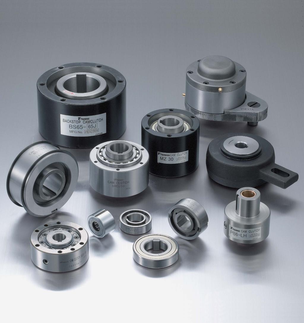
TSUBAKI CAM CLUTCH. TSUBAKI offers the most complete and versatile selection of one-way clutches in the industry. 200 Series.
|
|
|
- Jonah Lucas
- 6 years ago
- Views:
Transcription
1


2 TSUKI M LUTH TSUKI offers the most complete and versatile selection of one-way clutches in the industry. am lutches are precision devices which lock the inner and outer races, through the wedging action of cams, to transmit torque in one direction of rotation; and overrun in the opposite direction. These units are often referred to as freewheels, sprags, overrunning, backstop or one-way clutches, depending upon their application. Design eatures ull am omplement The full complement of cams provide the maximum number of load transmitting members per given diameter. The result is a greater torque capacity sizefor-size than other clutches. am Design Precision formed cams made of a special alloy steel provide extra long wear and fatigue life. High Quality omponents The clutch races are made of high-quality alloy steel with high surface hardness and core toughness. The races are precision ground, provide excellent concentricity and surface finish to obtain accurate cam rotation. MZ, MZ-G, MZEU Series Page 22 to 31 Series Page 32 Series Page TSS Series Page MZ Series clutch is prelubricated with a special grease and requires no lubrication maintenance. Ideal for general applications. The outer race of the MZ-G series is machine finished. MZEU series clutch is European style model. Series clutch is shaftmounted and prelubricated with special grease. The shaft must be supported by two bearings. series clutch has the bearing characteristics and dimensions of #62 type ball bearing. This design provides easy handling and installation. Ideal for general applications. TSS series clutch is designed for press fit installation. Outside dimensions are the same as series 62 ball bearings. This design provides easy handling and installation, ideal for general applications. MZ: ore Range: ø15 to ø mm Range: 186 to 3,0 N m MZ-G: ore Range: ø15 to ø mm Range: 186 to 3,0 N m MZEU:ore Range: ø12 to ø1 mm Range: to 33,0 N m ore Range: ø16.5 to ø79.3 mm Range: 39 to 1,3 N m ore Range: ø15 to ø mm Range: 29 to 2 N m ore Range: ø8 to ø mm Range: 6 to 649 N m TS Series Page 36 P Series Page 37 LD Series Page 38 MDEU Series Page 39 TS series clutch is designed for press fit installation. TS has two vertical keyways on the outer race. Outside dimensions are the same as series 63 ball bearings. This design provides easy handling and installation, ideal for general applications. P Series clutch is packed with a special grease for general applications. The outer race has provision for mounting gears, pulleys, and sprockets. LD Series clutch is packed with a special grease and requires no lubrication maintenance. This model is easily installed and ideal for light-duty applications. MDEU series clutch is European style model. earing is unnecessary due to cam and roller construction. Easy installation for sprocket, pulley or gear by using the Spirolox on the outer race. This enables to omit to make the flange for sprocket, pulley or gear, ideal for medium duty applications. ore Range: ø12 to ø mm Range: 18 to 3,924 N m ore Range: ø to ø mm Range: 29 to 2, N m ore Range: ø to ø mm Range: 5 to 49 N m ore Range: ø15 to ø mm Range: to 2,0 N m 1


3 MX Series Page MI-S Series Page 41 PO, PG, PS Series Page 42 MX Series clutch is best suited for indexing applications. This model ensures long life and accurate intermittent motion at the driven race. ore Range: ø22 to ø mm Range: 78 to 784 N m MI-S Series has special surface-treated cams for use in large feed angle indexing applications. ore Range: ø to ø mm Range: 43 to 196 N m These series are designed for use in printing machines, but can be used for general applications as well. PO and PG Series have swing arms. PS Series provides a precision feed action for seal printing machines. Range: PO: 44 to 441 N m PG: 19 to 58 N m PS: 196 to 392 N m S, S-HS, S-R, SEU Series Page 43 to R, R-P, REU Series Page 56 to 68 MG, MI, MR Series Page 69 MG-R Series Page 71 S Series clutch is exclusively used in backstop applications for conveyors and bucket elevators. SEU series clutch is European style model. S-HS Series offer higher torque and speed. R Series clutch is mainly used as backstop of inner race high-speed over running. R-P Series is the R Series with the bearings, REU series clutch is European style model. MG Series clutch is used for low to medium speed inner race overrunning. MI Series is for indexing applications. MR Series is for outer race highspeed overrunning applications. MG-R Series clutch with oil reservoir can be used in backstop service of inner race continuous and medium-speed overrun. S, :ore Range: ø to ø4 mm S-HS Range: 294 to 9,000 N m S-R: ore Range: ø to ø4 mm Range: 1,5 to 686,000 N m SEU: ore Range: ø to ø mm Range: 216 to 4,0 N m R: ore Range: ø to ø2 mm Range: 6 to 62,034 N m R-P: ore Range: ø to ø2 mm Range: 6 to 62,034 N m REU: ore Range: ø to ø1 mm Range: 7 to 33,8 N m MG, MI: ore Range: ø19 to ø2 mm Range: 314 to 176,000 N m MR: ore Range: ø85 to ø1 mm Range: 9,5 to 33,0 N m ore Range: ø19 to ø2 mm Range: 314 to 176,000 N m MZ-, MG- Series Page 72 O-ON Series Page 73 O-S, SN, S, PN Series Page T Series Page 76 MZ- Series clutch is clutch coupling utilizing MZ Series clutch. MG- Series clutch is clutch coupling utilizing MG Series clutch. O-ON Series is enclosed unit containing am lutch and shafts. They can be used for high-speed and continuous overrunning applications. Lubrication is by oil bath. These are enclosed units containing am lutch and shafts, and are used for high-speed and continuous overrunning applications. The lubrication methods are: T Series is enclosed unit containing am lutch and worm gear reducer for turning and inching applications. MZ-: ore Range: ø to ø mm Range: 323 to 3,0 N m MG-: ore Range: ø19 to ø1 mm Range: 314 to 33,0 N m Range: 314 to 5,8 N m S Self-lubrication with fins for water cooling External forced lubrication SN Self-lubrication PN Oil bath S Range: 3,1 to, N m Range: 3,1 to 24,0 N m Motor apacity: 0. to 22 kw Reduction Range: :1 to :1 2

4 Taking dvantage of Differences in Rotating Direction and Speed... TSUKI am lutches One-way clutches are efficient mechanical devices that utilize differences in axial rotating direction and the speed of rotation to prevent reverse rotation and ensure safety. In order to create a more reliable uni-directional clutch, engineers have spent many years developing and improving clutches, from the simple prop type, to the ratchet type and the roller type, and then culminating to the am lutch, which has become the mainstream. The TSUKI am lutch introduced here is a cam-type, one-way clutch that is the leading clutch of today. 3
5 STNDRD SPRG TYPE M LUTH ONSTRUTION The figure shows a typical model from the MZ Series for explaining construction. Major omponent Parts The major parts of the am lutch are the cams, inner race, outer race, springs and bearings. Each of these parts play an important role in the function of the am lutch. ll parts are made of carefully selected materials, have undergone appropriate heat treatment, and have passed strict quality control checks. Part am ppearance unction number of cams set regularly in between the inner and outer races function as props or sliders depending on the relative rotating directions of the inner and outer races. This action causes engagement (clutching) and disengagement (overrunning) of the clutch inner and outer races. The cams are the vital component of a am lutch, and they are available in various models and types to suit a variety of applications. Inner Race Outer Race The inner and outer sliding faces of the races are hardened and precisionground into a perfectly round cylinder to enable them to withstand the compressive stress generated during engagement with the cam and sliding abrasion when overrunning. Spring ompressed springs are set at both ends of the cams to ensure that all of the cams contact the inner and outer races at all times. Thus, the cams are always ready for immediate engagement. This is extremely important so as to ensure that the load is spread evenly across all cams when they engage with the inner and outer races. earing The bearings maintain concentricity of the inner and outer races and bear the radial load for the engagement of the cams and the inner and outer races. Maintaining concentricity is particularly important to ensure that the load is spread equally and simultaneously over the cams at the time of engagement. 4
6 R SERIES ONSTRUTION NON-ONTT DESIGN EXTENDS SERVIE LIE Greatly Increased Service Life Made possible by TSUKI s extensive experience in mechanical power transmission, the cam used in the R am lutch offers a unique cross section that provides positive mechanical engagement only when needed. Otherwise, the am lutch rotates freely with absolutely no mechanical contact in the clutch mechanism. The result is a greatly increased service life compared to conventional types. ackstop applications with high-speed overrunning When the am lutch is stationary, the cam locks the inner and outer races together (figure 1). When the inner race (load side) overruns at a high speed, the cam disengages by releasing from the inner race (figure 2). When the inner race stops, the cam rotates back into an engaged position. If the inner race tries to rotate in the reverse direction, the cams then serve as a prop between the anchored outer race and inner race to prevent the reverse rotation and provide backstopping. High-speed and low-speed-engaged overrunning When the am lutch is stationary, the cam locks the inner and outer races together (figure 1). When the inner race (load side) overruns at a high speed, the cam disengages by releasing from the inner race (figure 2). When the high-speed rotation of the inner race stops and the inner race begins to rotate slowly, the cam rotates back into an engaged position. Then when you start to drive the outer race at low speed of rotation, the cams serve as a prop and drive the inner race at the same low speed of rotation. more economical design. The open-type R series features a simple design in which the am lutch mechanism is incorporated in a cage between standard dimension inner and outer bearing races. This allows the am lutch to be easily and economically integrated into a wide variety of mechanical systems. package-type am lutch is also available to reduce maintenance demands. igure 1: Entire am lutch is stationary. igure 2: Inner race only turning. igure 3: Inner and outer race locked and turning. 5
7 MODES O OPERTION TSUKI am lutches are precision devices which lock to transmit torque in one direction of rotation, but overrun (freewheel) in the opposite direction of rotation. ll the series of clutches utilize the same principles of operation. Since clutch applications encompass a variety of load and speed characteristics, TSUKI am lutches are manufactured in a range of capacities and styles, which are designed to provide the best functional characteristics for performing in the following three basic modes of operation: 1. General overrunning lutches used in this type of application overrun at either the inner or outer race during the majority of the clutch operating time, and are occasionally called upon to lock up and drive. typical application is a two-speed drive, where an electric motor and a geared motor are connected to a single driven shaft through one-way clutches. The machine can be driven by either the electric motor or geared motor. When the geared motor drives at low speed, the clutch engages. When the electric motor drives the machine, the clutch overruns. The clutch automatically switches between low speed and high speed. 2. Indexing In this mode of operation, reciprocating motion applied to the driving race of the clutch is transformed into unidirectional intermittent motion, at the driven race. or example, on a feeding roller, the clutch is mounted on the roller and a torque arm is connected to the driving race of the clutch. crank motion mechanism provides reciprocating motion to the driving race. The clutch drives in the forward stroke (index) and overruns on the return stroke, resulting in intermittent unidirectional motion of the feeding roller. 3.ackstopping In backstop applications, the clutches are used to prevent reverse rotation of drive shafts, which may cause damage to machinery and other expensive equipment. With the outer race of the clutch anchored stationary, the inner race can overrun freely in one direction of rotation. Reverse rotation is instantaneously prevented by the automatic engagement of the clutch. Typical backstop applications are in conveyor systems and gear reducers. General Overrunning Indexing ackstopping ir cleaning plants gricultural machines ucket elevators ompressors onveyors ranes and hoists Dry cleaning machinery Duplicator equipment ish net machines Typical pplications Heat-treatment furnaces Induced draft fans Multi-state conveyors Packaging machinery Printing machinery Pumps Punch presses and feeders Power plants Refinery equipment Speed reducers Standby power units Textile looms Two-speed grinders Two-speed shiftovers Washing machines Wire winding machinery 6
8 M LUTH SELETION HRT lassification of pplications Modes of Operaion Overrunning Indexing ackstopping or Printing Machines ustom Design DUL DRIVE TWO SPEED DRIVE HIGH SPEED OVERRUN, ENGGEMENT OVERRUNNING : More than 0 r/min ( ENGGEMENT : More than 0 r/min ) HIGH SPEED OVERRUN, OVERRUNNING : More than 0 r/min LOW-MEDIUM SPEED ENGGEMENT ( ENGGEMENT : Less than 0 r/min ) HIGH SPEED OVERRUN, OVERRUNNING : More than 0 r/min LOW SPEED ENGGEMENT ( ENGGEMENT : Less than r/min ) LOW-MEDIUM SPEED OVERRUN, OVERRUNNING : Less than 0 r/min ENGGEMENT ( ) ENGGEMENT : Less than 0 r/min ENGGE IN ONE DIRETION, OVERRUN IN REVERSE DIRETION (Less than 0 r/min) REE WHEELING (Less than 0 r/min) MNUL DRIVE (Manual engagement) REQUENY : More than 0 times/min. HIGH SPEED, SMLL EED NGLE ( EED NGLE : Less than ) REQUENY : Less than 0 times/min. LOW-MEDIUM SPEED, SMLL EED NGLE ( ) LOW SPEED, LRGE EED NGLE KSTOP DEVIE OR INDEXING INDEXING URNISHED WITH STOPPER ININITE VRILE EED SINGLE YLE EED LOW SPEED OVERRUN (Less than 1 r/min) MEDIUM SPEED OVERRUN (1 to 0 r/min) HIGH SPEED OVERRUN (0 to 3,0 r/min) EED NGLE : More than REQUENY : Less than 1 times/min. EED NGLE : More than ( ) ( SME EED LUTHES OVE ) REQUENY : Less than 0 times/min. ( ) EED NGLE : Less than REQUENY : Less than 0 times/min. EED NGLE : Less than ( ) ( ENGGEMENT : Less than 0 r/min) INK ROLL DRIVE OR OSET DUPLITOR, RELIE DUPLITOR INK ROLL DRIVE OR OSET DUPLITOR, RELIE DUPLITOR (MNUL DRIVE) LEL PRINTING MHINE LEXO PRINTING MHINE USTOM DESIGNS VILLE ON REQUEST Series Selection 7
9 USE IN VRIOUS PPLITIONS To select the optimum am lutch, it is imperative that you thoroughly understand the application and conditions of use. The following explains the use of am lutches by application: irst confirm how the clutch you are going to use is classified, and then obtain detailed data from the relevant pages.. OVERRUNNING am behavior and am lutch operation In the case of a am lutch similar to the one shown on the right, the different conditions of engagement and disengagement for the various possible states are described below. These states are referred to as overrunning. 1. Outer race rotates counterclockwise. 1-1 When the outer race starts rotating counterclockwise from a standstill at N0 r/min, the am lutch engages and the inner race rotates in the same direction at N0 r/min. 1-2 When the inner race is rotated counterclockwise at N1 r/min by an outside force in the above state, and if N1 is faster than N0 (N1>N0), the am lutch overruns and the inner race rotates at N1 r/min, and the outer race at N0 r/min. 1-3 When N1 and N0 become equal, either by deceleration of N1 or by acceleration of N0, the am lutch engages again, and this continues as long as N0 is faster than N1 (N1<N0), and transmits torque from the outer race to the inner race. 2. Outer race rotates clockwise 2-1 When the outer race starts rotating clockwise from a standstill at N0 r/min, the am lutch overruns and the inner race remains at a standstill. 2-2 When the inner race is rotated clockwise at N1 r/min by an outside force in the above state, and if N0 is faster than N1 (N1<N0), the am lutch overruns and the inner race rotates at N1 r/min and the outer race at N0 r/min. 2-3 When N1 and N0 become equal, either by acceleration of N1 or by deceleration of N0, the am lutch engages, stays engaged, and transmits torque from the inner race to the outer race as long as N1 is faster than N If the inner race is rotated counterclockwise by another force, the am lutch continues overrunning irrespective of the speed of rotation. 8
10 -1. DUL DRIVE ND TWO-SPEED DRIVE Dual drive is a drive system in which two sets of driving units are installed instead of one driven unit, and the driven unit is driven by one or both of them as required. With dual drive, a drive system which has two sets of driving units having different speeds of rotation is referred to as two-speed drive, and the driven unit is driven at either high or low speed. Normally, each driving unit uses one am lutch which works as an automatic switcher for the driving units. In the figure on the right, when the driven unit is to be driven by driving unit in the direction of the arrow, am lutch engages to transmit the rotating power of the outer race to the inner race i.e., to the driven unit, and drives it at a preset speed of rotation. t this point, since the inner race of am lutch which is connected to the driven unit also rotates in the direction of the arrow, am lutch does not engage but overruns, thus disconnecting the driving unit from the driven unit. onversely, when the driven unit is to be driven by driving unit in the direction of the arrow, am lutch engages to transmit the rotating power of the outer race to the inner race, i.e., to the driven unit, and drives it at a preset speed of rotation. t this time, am lutch overruns to disconnect driving unit. am lutch applications are divided into four types (as indicated in the table on the right) depending on the overrunning speed and the engaging speed. pplication High-speed overrunning and high-speed engagement. High-speed overrunning and medium and low-speed engagement. High-speed overrunning and low-speed engagement. Medium and low-speed overrunning and medium and low-speed engagement. Overrunning speed 0 r/min and up 0 r/min and up 0 r/min and up Up to 0 r/min Engaging speed 0 r/min and up Up to 0 r/min Up to r/min Up to 0 r/min pplicable series am lutch ox, MZ, MZEU am lutch ox, MZ, MZEU am lutch ox, MZ, MZEU, MR, R, REU, T MZ, MG,, MZEU, P, LD Page 73 to, 22 to to, 22 to to, 22 to 31, 56 to 68, to 31, 37, High-Speed Overrunning and High-Speed Engagement (Overrunning speed = 0 r/min and up) (Engaging speed = 0 r/min and up) Example of fan or pump drive This example shows a high-speed system in which a driven unit (pump or fan) is driven by a dual drive system consisting of a motor and a turbine. The am lutches are used for automatic switching between the driving units. The fan is normally driven by the am lutch on the turbine side. When starting, or when steam pressure to the turbine drops, the motor takes over from the turbine to drive the fan. am lutch engages when the turbine drives the fan, and it overruns when the motor drives the fan. onversely, am lutch overruns when the turbine drives the fan, and it engages when the motor drives the fan. The driving devices can be changed over without switching the clutch. This is because the difference in the speed of rotation between the motor and turbine turns the am lutches on and off, and the driving device rotating the fastest is connected automatically to the driven unit. Overrunning and engagement of the am lutches are performed continuously at speeds faster than 0 r/min. 9
11 Example of energy saving pump (power recovery system) High-Seed Overrunning and Medium and Low-Speed Engagement (Overrunning speed = 0 r/min and up) (Engaging speed = up to 0 r/min) Example of energy saving drive for a soaking pit fan pplication of am lutches in an energy saving pump (power recovery system) shows how highly effective energy saving can be achieved with the aid of am lutches. The motor-driven pump discharges high-pressure liquid, which, after circulating, is used to drive a turbine. The turbine is then used to help drive the pump. If the pressure available is too low to rotate the turbine at high speed, the am lutch overruns. However, when the rotating speed of the turbine reaches the rotating speed of the motor, the am lutch engages automatically and the pump is driven by both the turbine, and the motor. Thus, power consumption equivalent to the turbine output can be saved. Since energy loss during overrunning and engagement of the am lutch is extremely small, this system produces results for pumps with an output as low as 7.5 kw. Setup requires only installation of a am lutch and a turbine, and provides a highefficiency energy recovery system with low running costs. pplicable Series Series dvantage Note Page am lutch an withstand extended Please specify ox continuous running. on the approval 73 O-ON Various lubricating and drawing that to O-SN cooling systems can be used. TSUKI issues O-S Minimal lubrication when you place O-S maintenance required. an order. MZ, MZEU Grease is sealed in, so lubrication maintenance is not required. 22 to 31 The am lutch works as a switcher for two driving units (high-speed or medium/low-speed). When driving a fan, cement kiln or conveyor in normal operation, the driving speed is switched to high speed. When using them for other purposes, the driving speed is switched to medium or low-speed. The figure above shows a soak pit fan used for melting aluminum and steel ingots, with a am lutch being used for energy saving. The heating is done in two stages, one being quick heating and the other being constant heating. Switching is done automatically by a driving system. or quick heating, the fan is driven by the main motor at high speed (the am lutch is overrunning at this time). or constant heating, since the fan only rotates at low speed, it is driven by a geared motor (the am lutch engages and the main motor and fan rotate simultaneously). ompared to pole change or inverter systems, great equipment cost savings can be made, and the initial equipment costs can be recovered very quickly. If equipment costs must be recovered within one year of continuous running, this system is effective for fans from the 15 kw class and up. pplicable Series Series dvantage Note Page am lutch ox O-ON O-PN MZ, MZEU an withstand extended continuous running. Minimal lubrication maintenance required. Grease is sealed in, so lubrication maintenance is not required. Please specify on the approval drawing that TSUKI issues when you place an order. 73 to 22 to 31 MR The cam is the outer race overrunning type that lifts off.
12 -1-3. High-Speed Overrunning and Low-Speed Engagement (Overrunning speed = 0 r/min and up) (Engaging speed = up to r/min) an Drive Systems pplicable Series Series dvantage Note Page am lutch ox O-ON O-PN T R, REU MZ, MZEU an withstand extended continuous running. Easy installation and space saving are possible with the T and TEW types that are combined with speed reducers. Minimal lubrication maintenance required. The cam is the inner race overrunning type that lifts off. Grease is sealed in, so lubrication maintenance is not required. Please specify on the approval drawing that TSUKI issues when you place an order. 73 to to to 31 MR The cam is the outer race overrunning type that lifts off. Smoke ventilation and gas mixing fans operate in high temperature environments. In order to prevent excessive thermal transfer from distorting the fan shaft, an auxiliary drive system is used to keep the fans rotating slowly when the main motor shuts down. Using a am lutch at the auxiliary motor eliminates the need for manual clutch operation. Thermal expansion in the fan shaft must be absorbed through an expandable coupling. During main motor operation, the am lutch rotates as a normal bearing, so service life is greatly extended. Turbine uxiliary Drive Systems This example shows a am lutch installed in the auxiliary drive system of a steam turbine. The auxiliary drive system powers the turbine at low speed through the engaged am lutch, until steam pressure accelerates the turbine to the am lutch release speed. Then the cam automatically disengages and runs as a high speed ball bearing, because there is no mechanical contact in the clutch. 11
13 -1-3. Medium and Low-Speed Overrunning and Medium and Low-Speed Engagement (Overrunning speed = Up to 0 r/min) (Engaging speed = Up to 0 r/min) In this application, one driven unit is driven at twospeeds by two medium and low-speed drive units, both at speeds lower than 0 r/min. Two am lutches enable automatic switching between the drive units. Example of pasting roll drive The above figure shows an example of am lutches being used with the pasting rolls of a corrugating machine for making cardboard. The pasting rolls are driven continuously by the main motor. During this time, am lutch engages and am lutch overruns. When the main motor must be stopped temporarily to fix a problem, it is necessary to keep rotating the pasting rolls in order to prevent paste on the roll surface from drying. To do this, the rolls are driven by an auxiliary motor at a low speed sufficient to prevent the paste from drying (am lutch overruns, while engages). This system is also used with meat choppers and screw feeds in food processing machinery. pplicable Series Series dvantage Page MZ, MZEU MG P Grease is sealed in, so lubrication maintenance is not required. ompact and transmits high torque. Excellent wear resistance when overrunning. Same dimensions as the #62 type bearing. Integrated am lutch and bearing. Sleeve-type outer race enables mounting of sprocket or gear with small outer diameter. Use of oil-impregnanted alloy bearings makes oiling to the bearing section unnecessary. Since this series is mounted directly on the shaft, it is possible to use a shaft of large diameter. ompact designs are possible. 22 to , 34 Grease is sealed in, so lubrication maintenance LD is not required. 38 or light loads and low-speed drive. TSS Outside dimensions ara the same as #62 type bering. ompact designs are possible. TS Outside dimensions ara the same as #63 type bering NORML ENGGEMENT REVERSE OVERRUNNING In this application, the normal rotating input power is held for a certain time and, after driving the driven side through the engagement of the am lutch, the am lutch is put into the overrunning state by reversing the input power. This application is classified into the following three kinds, depending upon the purpose for overrunning the am lutch: 1. To simply break the linkage between the input side and the driven unit (for details, see -2-1 below). 2. To make the driven unit rotate in reverse by drive from another source after making the input side rotate in reverse, and brake the load by engagement of the clutch when the speed of rotation of the driven unit has reached that of the input side (for details, see -2-2 below). 3. To selectively drive either one of the driven units or connected respectively to the outer races of the different aligned am lutches and, which are connected to the same drive shaft. When am lutch engages due to normal rotation of the shaft, am lutch overruns, and when am lutch engages due to reverse rotation of the shaft, am lutch overruns (for details, see -2-3 below) pplication requires breaking connection only (see the figure below) This example shows the use of a am lutch with an inclined pump. If the motor is wired in reverse by mistake at installation, it will rotate the pump in reverse. y mounting a am lutch between the motor and the pump, reverse rotation of the pump (which must not be allowed) is prevented because the am lutch will overrun if the motor rotates in reverse. The am lutch stays engaged at all times when the rotation is normal. Inclined pump 12
14 -2-2. pplication for the purpose of braking the driven side (see the figure below) The example here shows an application in which the hose drum of a pipe flusher is being driven. When the hydraulic motor is rotated in reverse in the counterclockwise direction, the am lutch inner race rotates in reverse, and the am lutch overruns. The flushing pump is driven in this state. The flushing water passes through the hose and gushes out of the nozzle toward the back. The force of this water jet starts the nozzle running and pulls and unwinds the hose. t the same time, the hose drum starts reverse rotation in the same counterclockwise direction, and increases its speed of rotation until it reaches the overrunning speed of the inner race. t this point, the am lutch engages, and the hydraulic motor works as a brake to stop the acceleration of the drum. Therefore, the running speed of the water jet nozzle is kept constant thereafter. When the hydraulic motor is rotated normally in the clockwise direction, the am lutch engages to wind the unwound hose onto the drum pplication for the purpose of selectively driving either one of two driven units by normal or reverse rotation of the drive input (see the figure below) When the motor is rotating normally (in the counterclockwise direction), am lutch engages to drive unit, and am lutch overruns. onversely, when the motor is rotated in reverse (in the clockwise direction), am lutch engages to drive driven unit. In this application, the two driven units must work independently. pplication in pipe flusher pplicable Series Series dvantage aution Page MZ, MZEU P LD MG MI TSS TS Grease is sealed in, so lubrication maintenance is not required. Same dimensions as the #62 type bearing. Integrated am lutch and bearing. Sleeve-type outer race enables mounting of sprocket or gear with small outer diameter. Use of oil-impregnated alloy bearings makes oiling the bearing section unnecessary. Since this series is mounted directly to the shaft, it is possible to use a large diameter shaft. ompact designs are possible. Grease is sealed in, so lubrication maintenance is not required. or light loads and low-speed drive. ompact and transmits high torque. Excellent wear resistance when overrunning. MG type reinforced spring type. Excellent response to load change. Outside dimensions ara the same as #62 type bering. ompact designs are possible. Outside dimensions ara the same as #63 type bering. When the engaged time is long and load change is considerable, choose the SS (reinforced spring) specification. In this specification, the response of cam following load changes during am lutch engagement is enhanced. Use the am lutch at an overrunning speed of r/min or lower. 22 to 31 33,
15 -3. REE WHEELING To prevent differences in the rotating speed between the driving side and the driven side from damaging the driving unit or the product, the am lutch overruns when speed differences occur. Normally, the am lutch engages to transmit torque, and it overruns to break the connection between the driving side and the driven side. In this case the am lutch overruns at a speed equal to the difference in rotating speed that occurs when the driven unit (normally the inner race) rotates faster than the driving unit (normally the outer race), or when the driving unit is decelerated or stopped abruptly. When feeding hoop-shaped material or plate material to the next process by slitter or pressure rolls, the material is fed at first by pinch rolls up to the main rolls. Since the main rolls process the material while pulling it at a speed faster than that of the pinch rolls, the pinch rolls are pulled by the material. t this point, the am lutch starts to overrun and prevents the pinch rolls from being driven in reverse by the material. The am lutch is used to prevent damage to the pinch roll driving parts and to the material, due to slippage between the pinch rolls. This method is also used with drying machines, engine testers, and plywood fabricating machines. -4. MNUL TYPE am lutches are used when a machine is operated manually for positioning, adjustment or inching. The am lutch mounted at the manual handle overruns while the machine is in operation. The handle does not rotate and cause a safety hazard. am lutches are used in the manual handles of circular knitting machines. The manual handle is used to operate the machine manually when starting, for adjustment of the needle and thread. When the machine starts its regular knitting work after the adjustment, the linkage between the am lutch and the handle is broken. nother am lutch is provided at the output section of the worm reduction gears, to break the connection with driving side during manual operation. Since this am lutch engages to drive the circular knitting machine during regular operation, the large torque capacity P12 is used. Manual operation example eed roll example pplicable Series Series dvantage Page MZ, MZEU Grease is sealed in, so lubrication maintanance is not required. 22 to 31 MG ompact and transmits high torque. 69 P LD MI TSS TS Same dimensions as #62 type bearing. Integrated am lutch and bearing. Sleeve-type outer race enables mounting of sprocket or gear with small outer diameter. Since this series is mounted directly on the shaft, it is possible to use a shaft of large diameter. Grease is sealed in, so lubrication maintenance is not required. or light loads and low-speed drive. Excellent response to load change. Outside dimensions ara the same as #62 type bering. ompact designs are possible. Outside dimensions ara the same as #63 type bering. 33, 34 SS Specification (reinforced spring specification) In this specification, the response of cam following load changes during am lutch engagement is enhanced. Use the am lutch at an overrunning speed of r/min or lower pplicable Series Series dvantage Page LD or low-speed overrunning. No maintenance. 38 MZ, MZEU or medium-speed overrunning. 22 to No maintenance. 31 or medium-speed overrunning. Since this series is mounted directly on the shaft, it is possible to use a shaft of large diameter. 32 Same dimensions as #62 type bearing. Integrated am lutch and bearing. 33, 34 P or medium-speed overrunning. Since it has a sleeve type outer race, it can be mounted easily on a handle with a small boss diameter. 37 PG TSS or low-speed overrunning. Outer race is tapped for mounting a lever. Outside dimensions ara the same as #62 type bering. ompact designs are possible. 42 TS Outside dimensions ara the same as #63 type bering. 36 or normal and reverse driving in the above examples, specially designed am lutches are available. Please contact TSUKI for details.


16 . INDEXING (INTERMITTENT EED) am ehavior and am lutch Operation In this application, reciprocal movement of a certain angle (θ) is provided at the outer race of the am lutch to perform engagement and overrunning in turn continuously and obtain intermittent rotation. In the case of the am lutch shown in the figure, when the outer race moves from to, the am lutch engages to rotate the inner race (of the driven side) by angle θ, i.e., from a to b. However, the am lutch does not operate to stop the inner race at position b. When the outer race rotates in reverse from to, the am lutch overruns while the inner race (of the driven side) does not rotate. y repeating this sequential movement, the inner race (of the driven side) rotates intermittently within the preset angle (θ). -1. HIGH SPEED ND SMLL EED NGLE (eed frequency: N = 0 to 1, times/min.) (eed angle: θ = Up to ; N θ=,000 max.) The example in the figure shows a roll feeding device which is frequently used in high-speed automatic clamp presses. Driving power is taken out of the eccentric disk provided at the end of the continuously rotating crankshaft, and this power drives the feed rolls intermittently through a am lutch. The feed length can be changed quickly and easily for improved work efficiency. In order to attain highspeed, high-precision feeding, a cone brake with less torque fluctuation and a am lutch for backstopping are used together. The am lutches in this application are designed for use in the range of (N θ),000. Please consult TSUKI regarding clutches for use outside of this range. Roll feeding device example dvantages of indexing mechanisms that use am lutches 1. ccurate feeding without backlash. 2. eeding distance can be simply adjusted and is stepless. 3. The indexing mechanism has low running costs. lassification into six applications Indexing (1) (2) (3) (4) (5) pplication Specification Page High speed and small feed angle Medium and low speed and small feed angle Low-speed and large feed angle ackstopping in intermittent feeding eeding with stopper (6) Speed change requency (number of rotations) = 0/min. and above eed angle (θ) : Up to requency (number of rotations) = 0/min. or less eed angle (θ) : Up to requency (number of rotations) = 1/min. or less eed angle (θ) : Up to requency and feed angle are the same as those of am lutches for feeding. pplication method is the same as (2) except that material is stopped by force during feeding. pplication method is the same as (2) except that the rotating speed is changed by steplessly changing the feed angle (θ) during operation eed accuracy [Specifications] lutch model : MX eed frequency : 0 times/min. eed length : 26.6 mm Load lnertia : 0.01 kg m 2 raking torque : 39.2 N m pplicable Series Series dvantage Page MX Suitable for high-speed indexing with a small feed length. High feeding accuracy is possible. 15
17 -2. MEDIUM ND LOW SPEED ND SMLL EED NGLE (eed frequency : N = Up to 0 times/min.) (eed angle : θ = Up to ; N θ=,000 max.) Indexing in this application range is applicable to many machines. The figure shows an example of use in the paper feeding section of an automatic stapler. The reciprocating movement of the eccentric disk is converted by the am lutch into an intermittent feed motion, which drives the belt conveyor. Hence, stapling is timed to the intermittent feeding motion and load overrun is prevented by a brake. Stapling is done at an exact pitch. This indexing can be applied extensively to food and other packaging machines. utomatic stapler example -3. LOW SPEED ND LRGE EED NGLE (eed frequency : N = Up to 1 times/min.) (eed angle : θ = and up; N θ=,000 max.) Segmented gears and rack & pinions are often used to produce the reciprocal movement to be transmitted to the am lutch. The figure below gives an application example of a pouch making machine. Since the reciprocal movement of the eccentric disk is accelerated through the rack & pinion assembly, the reciprocal action of the am lutch outer race is enlarged to 8. In this machine, the mm vinyl sheet feeding length is indexed at a speed of to times per minute. In this case, the acceleration of the am lutch increases, a large torque acts repeatedly, and the cam slipping distance at overrunning becomes longer. Hence, a cam is required that has superior engagement and higher anti-abrasive properties. brake is used in order to improve the precision of the vinyl sheet feeding pitch. eed roll example pplicable Series Series dvantage Page MI MZ, MZEU P or medium speeds (up to 0 times/min.). Since a free-action type cam retainer is used, the cam has excellent follow-up response at the time of engagement. or low speed (up to 1 times/min.). No maintenance. or low speed (up to 1 times/min.). Since this series is mounted directly on the shaft, it is possible to use a shaft of large diameter. or low speeds (up to times/min.). Same dimensions as #62 bearing. or low speeds (up to 1 times/min.). Sleeve-type outer race enables mounting of sprocket or gears as well as torque arms with small boss diameter to , 34 LD or low speeds (up to times/min.). or light loads, no maintenance. 38 or medium speeds (up to 0 times/min.). MI-S Use of a cam finished by special surface 41 hardening improves abrasion resistance. PO or low speeds (up to 1 times/min.). swing arm is mounted for easy handling. 42 or low speeds (up to 1 times/min.). PS Suitable especially when higher precision is 42 required. MX or high speeds (up to 1, times/min.). pplicable also to low speeds. or low speeds (up to times/min.). PG Since a swing arm is mounted, it can be used 42 simply by mounting it on the shaft. 37 pplicable Series Series dvantage Page MI-S The MI-S Series has been developed exclusively for these applications. Special cam surface hardening treatment improves the abrasion resistance. The shape and structure of the cam are specially designed so that it can handle abrupt speed changes (e.g. great acceleration) when engaging
18 -4. KSTOPPING IN INTERMITTENT EEDING am clutch and feed accuracy When designing a high-accuracy feeding device that incorporates am lutch indexing, both the driving and driven units must be made light in weight and high in rigidity. Moreover, when selecting the ideal am lutch, it is extremely important to select a brake to stop the driven unit at a preset position, a positioning device, and a am lutch for backstopping (which cannot be expected of the am lutch for indexing). eed accuracy = am lutch for indexing + am lutch for backstop + rake am lutch for backstopping This am lutch overruns when the am lutch for indexing has completed one feeding stroke. If the frictional resistance of the driven unit is smaller than the overrunning frictional torque of the am lutch, or if a reverse torque occurs on the driving side due to back MX Series tension of the material, the driven unit may rotate in reverse without stopping at the end point fed by the am lutch. The most effective way to prevent this is to mount a am lutch for backstopping, although a brake or positioning pin may also be used for this purpose. Since the am lutch for backstopping repeats the overrunning and engagement at the same frequency as that of the am lutch for indexing, use one that is equivalent to the feeding clutch or one that is one size smaller. rakes and other stopping devices The outer race of a am lutch for indexing starts reverse rotation immediately upon the completion of one feeding stroke. t the same time, the am lutch starts overrunning. t this moment, the driven unit is free from all restrictions, and therefore, when the driven unit has a one brake larger inertia or the feed speed is faster, the inner race tends to rotate beyond the stroke of the outer race. To prevent this, a friction brake is often used as a braking device, although a positioning pin or stopper may also be used for this purpose. braking device significantly improves the feed accuracy. ccordingly, use a frictional brake which has as small a fluctuation as possible in its braking force. The wet-type cone brake is most effective. Please consult TSUKI regarding brake selection. -5 EEDING WITH STOPPER (eed frequency = Up to 0 times/min.) (eed angle = up to ) In this application, a stopper forcibly stops the material to be indexed at a position just before the feed end point, to obtain a fixed feeding pitch. s soon as the material hits the stopper, a shock torque larger than the torque required for feeding is applied to the feeding roll which is still rotating. The figure below shows an example of a am lutch used in a bolt header. The wire is fed intermittently by a am lutch mounted on a grooved feed roll. Since the feed length of the wire is set longer than necessary, the fed wire hits the stopper which has been set at a position where the wire can be fed at the necessary length. The reactive force this generates acts as vibrating shock load upon the am lutch. It is therefore necessary to consider this when selecting a am lutch. Example of bolt header pplicable series onsult TSUKI. autions When setting the feed length, consider the following: eed length setting = Necessary length + α The closer to zero α is, the smaller the vibrating shock load on the am lutch becomes and consequently, the longer the service life becomes. 17
19 -6. SPEED HNGE (eed frequency : N = Up to 0 times/min.) (eed angle : θ = Up to ; N θ=,000 max.) In an intermittent feed mechanism that uses one or more am lutches, the speed of the driven side is changed steplessly by changing the feed angle. The figure below shows an example of a sprinkler (manure spreader). The amount of manure to be sprinkled, which varies depending on the field conditions, must be adjusted case by case. The chain conveyor is driven by an intermittent am lutch feeding action and the manure loaded on the cart is fed in bits to the sprinkling vanes, which rotate continuously. The manure to be sprinkled can thus be kept at the optimum amount by adjusting the amount of manure to be fed. The feed amount (or angle of the am lutch) can be controlled steplessly while the sprinkler is operating. Structure of speed controlling section pplicable Series Series dvantage Page MI-S or medium speeds (Up to 0 times/min.) 41 MI or medium speeds (Up to 0 times/min.) 69 MZ, MZEU P or low speeds (Up to 1 times/min.) or low speeds (Up to 1 times/min.) 22 to 31 LD or low speeds (Up to times/min.) and light loads Sprinkler example 18
20 . KSTOPPING TO PREVENT REVERSE ROTTION ackstopping is used to prevent the rotating shaft from rotating in the reverse direction. The am lutch continues overrunning while the shaft rotates normally, and it engages to prevent reverse shaft rotation just before it is about to occur. ehavior and function of am lutch Normally, the inner race is mounted on the rotation shaft, and the outer race is fixed to the machine frame. The inner race is thus set on the overrunning side. s soon as the shaft begins to rotate in reverse, the cams engage with the inner and outer races to prevent reverse rotation and support the load. Prevention of reverse rotation of inclined and vertical conveyors is a typical example of how backstopping is used. The following,, and types are available for different am lutch mounting positions, and the series listed are designed to handle each specification. Type of mounting Mounting position Pulley shaft ackstopping for mediumspeed overrunning Intermediate shaft of reduction gears Directly connected to motor shaft Use ackstopping for low-speed overrunning ackstopping for high-speed overrunning,, and mounting types Specification (overrunning speed/ reversing torque) 0 to approx. 1 r/min.; Large reversing torque. pprox. 1 to 0 r/min.; Medium reversing torque. 0 to 3,0 r/min.; Small reversing torque. pplicable series S S-R SEU MG-R R REU Page 43 to to 66 Three classifications ackstopping is classified into three types depending on the overrunning speed and load conditions. ackstopping Purpose of use Overrunning speed Engagement ackstopping for lowspeed overrunning ackstopping for mediumspeed overrunning ackstopping for high-speed overrunning ontinuous overrunning at 1 r/min or less ontinuous overrunning at 1 to 0 r/min ontinuous overrunning at 0 to 3,0 r/min Irregular, low-frequency engagement Major applications or backstopping of conveyor shafts, pumps, etc. or backstopping of intermediate shafts of conveyordrive reduction gears. or backstopping of high-speed rotating shafts in conveyor-drive machines, pumps, etc. Page 19
21 -1. KSTOPPING OR LOW-SPEED OVERRUNNING (Overrunning speed at 1 r/min or less) In this application, the inner race of the am lutch is mounted directly onto the conveyor head pulley, or other shaft with a lowspeed of rotation, while the outer race is anchored to the conveyor frame to prevent reverse rotation. Since reverse rotation is prevented directly by the conveyor shaft without using a drive chain, gears, or couplings, this is regarded as the safest and most reliable mounting method. dditionally, a low overrunning speed minimizes the cam overrunning slip speed, as well as the overall slipping distance. s a result, wear on the cam is reduced and a prolonged service life can be expected. In addition to conveyors, this system is also used to prevent reverse rotation in inclined and screw pumps. pplicable Series Series dvantage Page S S-HS S-R SEU am lutch designed for conveyor backstopping. Designed to be perfectly dust-proof. Lubrication is greatly enhanced by the cam-roller combination. Grease is sealed in, so lubrication maintenance is almost never required. Depending on conditions, the following series can also be used for this purpose: MG (p. 69), MG-R (p.71), MZ, MZEU (p. 22 to p. 31), (p. 33), P (p. 37), (p. 32) and LD (p. 38) Series -2. KSTOPPING OR MEDIUM- SPEED OVERRUNNING (Overrunning speed = 1 to 0 r/min) In this application, the am lutch is mounted on shafts rotating at medium speeds, such as the intermediate shafts of reduction gears, etc., to prevent reverse rotation. Since reverse rotation is prevented by the medium-speed shaft, the am lutch required only needs to withstand a comparatively small torque which is inversely proportional to the rotating speed ratio of the conveyor shaft. ccordingly, even a small-sized am lutch can be used for this purpose. 43 to pplicable Series Series dvantage Page MG-R The oil reservoir provided with this series accommodates a large amount of oil to reduce maintenance. ompact and able to transmit large torques. Excellent wear resistance when overrunning. Since this series is mounted directly on the shaft, it is possible to use shafts of large diameters. Ideal for use with reduction gears. The following series, which have sealed-in grease and are maintenance free, can also be used for this purpose: MZ, MZEU (p. 22 to p.31), MG (p. 65) and P (p. 37) Series. -3. KSTOPPING OR HIGH-SPEED OVERRUNNING (Overrunning speed = 0 to 3,0 r/min) This example shows a am lutch installed to the motor shaft of an inclined conveyor system, to prevent reverse rotation. Low torque am lutches can also be installed to high speed shafts. am lutches are excellent for space-limited applications because they can be used as is for replacements for standard ball bearing cassettes. This example shows a am lutch installed to a motor pulley to prevent reverse rotation. am lutches can be installed to inclined belt conveyor systems to prevent reversing when the conveyor stops, as a result of power loss or other causes pplicable Series Series dvantage Page Same dimensions as #62 bearing unit. One-piece construction of bearing and am lutch. 33, 34
22 There are many cases in which large scale vertical motor or pump systems must be kept from turning backwards am lutch can be installed above the motor of a vertical motor system, or on the mainshaft of a vertical pump, to provide this function. nchoring the outer race of the am lutch will prevent the inner race from rotating in the reverse direction. Many liquid media transmission systems use multiple pumps or compressors feeding into the same line, to save energy or provide emergency backup functions. System pressure will often cause the pump or compressor to back-spin when not running. am lutch can prevent this. Pump and compressor systems Pump & ompressor Systems or reasons of safety, belt conveyors must be prevented from moving backwards. Installing a am lutch on the main motor shaft is the easiest and most economical method for this. or certain large and midscale belt conveyors with high lift distances, it may be more economical to install the am lutch on one of the high speed shafts. In these cases it is important to verify the torque load applied to the engaged clutch. Large scale inclined belt conveyors pplicable Series Series dvantage Page R, REU The cam is the inner race overrunning type that lifts off. 56 to 68 21
 y Side plate u Snap ring G Dimensions and apacities MZ15 MZ17 MZ MZ-22 MZ- MZ MZ MZ- MZ MZ- MZ- MZ MZ-65 MZ")
 1 1 1 1 1 1 1 1 ore Size Dia (H7) 15 17 22 65 Keyway 5 2.3 5 2.3 6 2.8 6 2.8 8 3.3 3.3 3.3 12 3.3 14 3.8 14 3.8 16 4.3 18 4.4 18 4.4 4.")
 1.4 1.8 2.0 3.7 4.8 6.2.2 13.2 Installation and Usage 1.")
23 MZ SERIES M LUTH MODELS MZ 15 TO MZ or General pplications eatures: 1. Prelubricated with special grease 2. No lubrication maintenance required. 3. Easy installation and handling q Inner race w Outer race e am r Spring t earing (ZZ type) y Side plate u Snap ring G Dimensions and apacities MZ15 MZ17 MZ MZ-22 MZ- MZ MZ MZ- MZ MZ- MZ- MZ MZ-65 MZ apacity (N m) ,0 1,6 2, 3,0 Drag (N m) Max. Overrunning (r/min) Inner Race 2, 2,000 1,0 1,0 1,0 1,0 1,0 1,0 Outer Race Max. indexing (cycle/min) ore Size Dia (H7) Keyway PD D E (M6) G H-M No. of Tapped Holes Size Pitch 6 M5 P0.8 6 M5 P0.8 6 M6 P 6 M8 P1. 6 M8 P1. 8 M8 P1. 8 M8 P1. 8 M8 P1. S Weight (o) Installation and Usage 1. MZ Series am lutch is Shielded by shield bearings on both ends, packed with a special grease, and are ready for use. No additional lubricant is required. 2. or attaching pulleys, gears or sprockets to the clutches, insert hubs (with f7 tolerance of ISO R773) along the inner surface of the outer race and screw the bolts (high tension) into the tapped holes on the clutch end. MZ15 MZ17 MZ MZ MZ MZ MZ MZ Nominal diameter (mm) Relative shaft tolerance (mm) +0 to to to to to to to to Recommended shaft tolerances are shown in the table on the lower left. 4. External thrust load should be supported by other devices, not by the am lutch. 5. Use only a parallel key to secure the clutch to the shaft. Do Typical installation not use a tapered Key. 6. When mounting the clutch onto the shaft, apply pressure to the inner race but never to the outer race. See the illustration on the right. 7. or vertical mounting, please consult TSUKI. 8. mbient temperature range is 5 to. 9. Key to be used should be in accordance with ISO R773. (DIN ) 22
24 MZ-G SERIES M LUTH MODELS MZ 15G TO MZ G or General pplications eatures: 1. Outer race circumference ground finish apacities q Inner race w Outer race e am r Spring t earing (ZZ type) y Side plate u Snap ring MZ15G MZ17G MZG MZG-22 MZG- MZG MZG MZG- MZG MZG- MZG- MZG MZG-65 MZG apacity (N m) ,0 1,6 2, 3,0 Max. Overrunning (r/min) Inner Race 2, 2,000 1,0 1,0 1,0 1,0 1,0 1,0 Outer Race Max. Indexing (cycle/min) Drag (N m) Dimensions MZ15G MZ17G MZG MZG-22 MZG- MZG MZG MZG- MZG MZG- MZG- MZG MZG-65 MZG Dia. (H7) ore size Keyway hamfer J (h7) E K PD D S H-M No.of Tapped Holes Size Pitch 6-M M M6 6-M M M M M8 1. Weight (o) Installation and Usage 1. When mounting sprockets or gears to the outer race, use the outer race outer dimension (dimension ) to make a centering flange in the gear or sprocket. Then attach firmly with bolts of tensile strength.9 or greater to the tapped holes in the outer race. 2. Please refer to MZ Series for usage and other types of installations. Typical installation MZ-G Series 23
 MZEU 15 (K) MZEU (K) MZEU (K) MZEU (K) MZEU (K) MZEU (K) MZEU (K) MZEU (K) MZEU (K) MZEU (K) MZEU (K) MZEU (K) MZEU (K) MZEU (K)")
25 MZEU SERIES M LUTH asic type K H J q Inner race w Outer race e am r Spring t earing y Side plate D L E G This drawing shows MZEU Dimensions and apacities Max. Overrunning apacity Inner Race Outer Race N m r/min r/min MZEU 12 (K) MZEU 15 (K) MZEU (K) MZEU (K) MZEU (K) MZEU (K) MZEU (K) MZEU (K) MZEU (K) MZEU (K) MZEU (K) MZEU (K) MZEU (K) MZEU (K) MZEU (K) MZEU1 (K) MZEU1 (K) ,015 1,3 1,6 2,0 2,0 2,9 4,2 5,1 12,000 17,0 24,0 33,0 2,000 1,0 1,0 1,0 1,0 1,0 1,0 1,0 1,0 1,0 1, 1, , Drag N m ore Size H Keyway Inner Race h D PD E G H J M5 4 M5 4 M6 6 M6 6 M6 6 M8 8 M8 8 M8 8 M M M M M12 M16 12 M16 12 M K L Weight (o) Installation and Usage 1. No s. MZEU12 to MZEU are pre-greased and require no lubrication. The operational temperature range is to +. No s. MZEU to MZEU1 require oil lubrication. (Refer to lubrication and maintenance on page 31). 2. No s. MZEU12 to MZEU sprockets and other torque transmitting factors can be used with the standard flange. Refer to installation example We recommend a Shaft tolerance of h7, and ISO R773 (DIN ) keyway is standard. 4. We recommend a tolerance of E H7 for the sprocket and other parts. 5. lean the surface of both ends of the outer race and the contact surfaces of the flange, sprocket and the other parts. 6. or No s. MZEU to MZEU1, apply seal adhesive to the surface of the outer race at both ends. 7. heck the direction of rotation. 8. When installing standard flanges, sprockets and other equipment to the clutch fit them around the bearings and screw the bolts into both ends of the outer race. 9. y installing both the flange and sprocket on the opposite side, the direction of rotation can be changed.. When mounting the clutch onto the shaft, apply pressure to inner race but never to the outer race. 11. or high speed Indexing applications (More than c/m) a strong spring type is recommended. 12. No. MZEU K No Mark : No keyway on the outer race. K : Keyway on the outer race. 24 Typical installation 1 E2

26 E1 lange + E2 lange D L q Inner race w Outer race e am r Spring t earing y Side plate u E1 lange i E2 lange o Socket bolt!0 Set screw N 1 M O-P This drawing shows MZEU E1+E2 Dimensions and apacities Max. Overrunning apacity Inner Race Outer Race N m r/min r/min MZEU 12 (K) E1+E2 MZEU 15 (K) E1+E2 MZEU (K) E1+E2 MZEU (K) E1+E2 MZEU (K) E1+E2 MZEU (K) E1+E2 MZEU (K) E1+E2 MZEU (K) E1+E2 MZEU (K) E1+E2 MZEU (K) E1+E2 MZEU (K) E1+E2 MZEU (K) E1+E2 MZEU (K) E1+E2 MZEU (K) E1+E2 MZEU (K) E1+E2 MZEU1 (K) E1+E2 MZEU1 (K) E1+E ,015 1,3 1,6 2,0 2,0 2,9 4,2 5,1 12,000 17,0 24,0 33,0 2,000 1,0 1,0 1,0 1,0 1,0 1,0 1,0 1,0 1,0 1, 1, , Drag N m ore Size H Keyway Inner Race h D L M N O P Weight (o) Installation and Usage 1. No s. MZEU12 to MZEU are pre-greased and require no lubrication. The operational temperature range is to +. No s. MZEU to MZEU1 require oil lubrication. (Refer to lubrication and maintenance on page 31). 2. We recommend a Shaft tolerance of h7, and ISO R773 (DIN ) keyway is standard. 3. We recommend tolerances of H7 or H8 for sprockets, gears and other fitted parts. 4. The clutch is delivered with a asic type am lutch, E1 flange and E2 flange as separate parts. 5. lean the surface of both ends of the outer race and the contact surfaces of the flanges. 6. or No s. MZEU to MZEU1, apply seal adhesive to the surface of the outer race at both ends. 7. heck the direction of rotation and attach the E1 and E2 flanges to clutch. 8. When installing sprockets, gears and other equipment to the clutch, fit them on the surface of the outer race and screw the bolts into the E1 flange. 9. y installing both the flange and sprocket on the opposite side, the direction of rotation can be changed.. When mounting the clutch onto the shaft, apply pressure to inner race but never to the outer race. 11. or high speed Indexing applications (More than c/m) a strong spring type is recommended. 12. No. MZEU K No Mark : No keyway on the outer race. K : Keyway on the outer race. E1 Typical installation 2 E2

27 E2 lange + E3 arm R Q S L q Inner race w Outer race e am r Spring t earing y Side plate u E2 lange i E3 arm o Pin!0 Set screw!1 Socket bolt!2 Set screw T M This drawing shows MZEU E2+E3 Dimensions and apacities Max. Overrunning apacity Inner Race Outer Race N m r/min r/min MZEU 12 (K) E2+E3 MZEU 15 (K) E2+E3 MZEU (K) E2+E3 MZEU (K) E2+E3 MZEU (K) E2+E3 MZEU (K) E2+E3 MZEU (K) E2+E3 MZEU (K) E2+E3 MZEU (K) E2+E3 MZEU (K) E2+E3 MZEU (K) E2+E3 MZEU (K) E2+E3 MZEU (K) E2+E3 MZEU (K) E2+E3 MZEU (K) E2+E3 MZEU1 (K) E2+E3 MZEU1 (K) E2+E ,015 1,3 1,6 2,0 2,0 2,9 4,2 5,1 12,000 17,0 24,0 33,0 2,000 1,0 1,0 1,0 1,0 1,0 1,0 1,0 1,0 1,0 1, 1, , Drag N m ore Size H Keyway Inner Race h L M Q R S T Weight (o) Installation and Usage 1. No s. MZEU12 to MZEU are pre-greased and require no lubrication. The operational temperature range is to +. No s. MZEU to MZEU1 require oil lubrication. (Refer to lubrication and maintenance on page 31). 2. We recommend a Shaft tolerance of h7, and ISO R773 (DIN ) keyway is standard. 3. The clutch is delivered with a asic type am lutch, E2 flange and E3 torque arm as separate parts. 4. lean the surface of the outer race at both ends and the contact surfaces of the E2 flange and the E3 torque arm. 5. or No s. MZEU to MZEU1, apply seal adhesive to the surface of the outer race at both ends. 6. heck the direction of rotation and attach the E2 flange and the E3 torque arm to the clutch. 7. y installing both the flange and sprocket on the opposite side, the direction of rotation can be changed. 8. When mounting the clutch onto the shaft, apply pressure to inner race but never to the outer race. 9. or high speed Indexing applications (More than c/m) a strong spring type is recommended.. No. MZEU K No Mark : No keyway on the outer race. K : Keyway on the outer race. Typical installation 3 26

28 E3 arm + E4 over R Q S 1 L U q Inner race w Outer race e am r Spring t earing y Side plate u E3 arm i E4 over o Pin!0 Set screw!1 Hollow hex bolt!2 Set screw T M This drawing shows MZEU E3+E4 Dimensions and apacities Max. Overrunning apacity Inner Race Outer Race N m r/min r/min MZEU 12 (K) E3+E4 MZEU 15 (K) E3+E4 MZEU (K) E3+E4 MZEU (K) E3+E4 MZEU (K) E3+E4 MZEU (K) E3+E4 MZEU (K) E3+E4 MZEU (K) E3+E4 MZEU (K) E3+E4 MZEU (K) E3+E4 MZEU (K) E3+E4 MZEU (K) E3+E4 MZEU (K) E3+E4 MZEU (K) E3+E4 MZEU (K) E3+E4 MZEU1 (K) E3+E4 MZEU1 (K) E3+E ,015 1,3 1,6 2,0 2,0 2,9 4,2 5,1 12,000 17,0 24,0 33,0 2,000 1,0 1,0 1,0 1,0 1,0 1,0 1,0 1,0 1,0 1, 1, , Drag N m ore Size H Keyway Inner Race h L M Q R S T U Weight (o) Installation and Usage 1. No s. MZEU12 to MZEU are pre-greased and require no lubrication. The operational temperature range is to +. No s. MZEU to MZEU1 require oil lubrication. (Refer to lubrication and maintenance on page 31). 2. We recommend a Shaft tolerance of h7, and the DIN keyway is standard. 3. The clutch is delivered with a asic type am lutch, E3 torque arm and E4 cover as separate parts. 4. lean the surface of both ends of the outer race and the contact surface of E3 torque arm and E4 cover. 5. or No s. MZEU to MZEU1, apply seal adhesive to the surface of the outer race at both ends. 6. heck the direction of rotation and attach the E3 torque arm to the clutch. 7. y installing both the flange and sprocket on the opposite side, the direction of rotation can be changed. 8. When mounting the clutch onto the shaft, apply pressure to inner race but never to the outer race. 9. or No s. MZEU12 to MZEU, before mounting the E4 cover to the clutch attach the end plate with bolts. Refer to installation example 4.. or No s. MZEU to MZEU1, before mounting the cover attach the packing and end plate using sealing washers and bolts. Refer to installation example No. MZEU K No Mark : No keyway on the outer race. K : Keyway on the outer race. 27 Typical installation 4 Grease lubrication rom MZEU12 to MZEU

29 E5 lange + E5 lange D L b t1 q Inner race w Outer race e am r Spring t earing y Side plate u E5 lange i Hex socket cap bolt o Set screw 1 M 8 This drawing shows MZEU K E5+E5. Dimensions and apacities MZEU 12 K E5+E5 MZEU 15 K E5+E5 MZEU K E5+E5 MZEU K E5+E5 MZEU K E5+E5 MZEU K E5+E5 MZEU K E5+E5 MZEU K E5+E5 MZEU K E5+E5 MZEU K E5+E5 MZEU K E5+E5 MZEU K E5+E5 MZEU K E5+E5 MZEU K E5+E5 MZEU K E5+E5 MZEU1 K E5+E5 MZEU1 K E5+E5 apacity N m Max. Overrunning Inner Race Outer Race r/min r/min Drag N m ore Size H Keyway Inner Race h D L M b P t Weight (o) Installation and Usage 1. The clutch is delivered with a asic type am lutch, two E5 flanges, and flange kit as separate parts. 2. heck the direction of rotation and attach an E5 flange to the clutch by the bolt. 3. When installing sprocket, gear and other equipment to the clutch, install them on the outer race and fix the key between the equipment and the outer race. 4. We recommend a tolerance of H7 for the bore of the sprocket, gear or other equipment. 5. ttach the opposite side E5 flange to the clutch by the bolts. 6. y installing the clutch to the shaft on the opposite side, the direction of rotation can be changed. 7. When mounting the clutch onto the shaft, apply pressure to the inner race but never to the outer race. 8. or high speed indexing applications (More than c/min) a strong spring type is recommended. 9. Refer to page 31 for other usage.. E5+E5 flange is available only for MZEU K model. E5 lange E5 lange Typical installation 5 28

30 E2 lange + E7 lange D DI L q Inner race w Outer race e am r Spring t earing y Side plate u E2 lange i E7 lange o Hex socket cap bolt!0 Set screw 1 M O-P N 1 This drawing shows MZEU K E2+E7. Dimensions and apacities Max. Overrunning MZEU 12 (K) E2+E7 MZEU 15 (K) E2+E7 MZEU (K) E2+E7 MZEU (K) E2+E7 MZEU (K) E2+E7 MZEU (K) E2+E7 MZEU (K) E2+E7 MZEU (K) E2+E7 MZEU (K) E2+E7 MZEU (K) E2+E7 MZEU (K) E2+E7 MZEU (K) E2+E7 MZEU (K) E2+E7 MZEU (K) E2+E7 MZEU (K) E2+E7 MZEU1 (K) E2+E7 MZEU1 (K) E2+E7 apacity N m Inner Race r/min Outer Race r/min Drag N m ore Size H Keyway Inner Race h D1 h D L M N O P Weight (o) Installation and Usage 1. The clutch is delivered with a asic type am lutch, E2 flange, E7 flange and each flange kit as separate parts. 2. heck the direction of rotation and attach the each flange to the clutch. 3. When installing sprocket, gear and other equipment to the clutch, fit them on the surface of the outer race or flange and screw the bolt in to them. 4. y installing both option parts on the opposite side, the direction of rotation can be changed. 5. When mounting the clutch onto the shaft, apply pressure to the inner race but never to the outer race. 6. or high speed indexing applications (more than c/min) a strong spring type is recommended. 7. Refer to page 31 for other Usage. 8. No. MZEU K No Mark : No keyway on the outer race. K : Keyway on the outer race. Notes: Do not apply a large overhung load to the outer race by using E7 flange to keep the centerline between the inner and outer race. Typical installation 6 E7 lange E2 lange 29
31 OUPLING q MZEU cam clutch w E2 lange e Sprocket r Sprocket t Roller chain I G E D 1 H J S J Specify right (RH) or Left hand (LH) drive viewed from this end inner race driving. This drawing shows MZEU K E2+. Dimensions and apacities Max. Overrunning apacity Inner Race Outer Race N m r/min r/min MZEU12 (K)- MZEU15 (K)- MZEU (K)- MZEU (K)- MZEU (K)- MZEU (K)- MZEU (K)- MZEU (K)- MZEU (K)- MZEU (K)- MZEU (K)- MZEU (K)- MZEU (K) ,015 1,3 1,6 2,0 2,0 2,9 4,2 5,1 2,000 1,0 1,0 1,0 1,0 1,0 1,0 1,0 1,0 1,0 1, 1, 0 1, Drag N m H lutch Side ore Size Keyway oupling Side ore Size Range min. max h D E G H I J S Installation and Usage 1. MZEU (K)- series am lutch couplings make use of MZEU (K) series and R type couplings without cover. 2. Mount the am lutch loosely on the high speed shaft at first. 3. ccurately align both sprockets by checking with a straight edge on the teeth of both sprockets. 4. heck whether the clearance(s) between both sprokets are correct, then wrap the chainaround the sprockets. 5. Specify right hand (RH) or left hand (LH) as inner race overrunning direction from the view of am lutch side (*) See the above drawing. 6. The same lubricaion as for Tsubaki roller chain is necessary for the coupling chain. 7. Ensure that the chain is properly closed with a connecting link and that the closed of the spring clip is installed in the same direction as the rotation of the outer race. 8. No. MZEU K No Mark : No keyway on the outer race. K : Keyway on the outer race.
32 LURITION ND MINTENNE No s. MZEU12 to MZEU are pre-greased and require no lubrication. The operational temperature range is to +. No s. MZEU to MZEU1 require oil lubrication. Recommended Grease for No s. MZEU12 to MZEU rand 5 ~ + Exxon Mobil Shell lvania Grease S2 P Energrease LS2 TOTL Multis 2 Note: Do not use oil that contains EP additives. E1~E4 options are supplied with bolts for installation, and grease nipple. mbient Temperature ~ + eacon 3 Mobil temp SH lvania Grease R Enargrease LT2 erogrease 22 Recommended oil for MZEU to MZEU1 mbient Temperature rand ~ + Teresso 32, Essolub D-3 W, T Dexron Exxon Mobil T 2, Delvac 13, DTE oil Light Dexron 2, Rimula T oil W, Shell Shell lavus Oil 17, Rotella S Oil W P P Energol TH32 Gulf Harmony 32 Note: Do not use oil that contains EP additives. Note: ody (asic type) is supplied with sealing adhesive. + ~ + Essolub D-3 Delvac 13 Rimula T Oil W/, Rotella S Oil W/, Oil lubrication Sealing adhesive application area. Packing Sealing washer Oil level Oil plug Oil plug heck plug (check oil level) heck plug (check oil level) Sealing bond application area. Drain plug Drain plug rom MZEU to MZEU1 rom MZEU to MZEU rom MZEU1 to MZEU1 Installation example 5 Drawing to explain about lubrication 1. pply a suitable amount of oil before use. 2. s a general rule, the amount of lubricant should be level with the center of the shaft for overrunning or backstopping. 3. The E2 flange has three plugs. The E4 cover has a large plug for adding oil and two small plugs for checking and draining. 4. Place the plugs, so that one is at the top and one is at the bottom. The center one should be level with the center of the shaft. 5. Pour oil into the clutch until it overflows from check plug. fter a few minutes, pour in more oil and check that it overflows again. Maintenance MZEU12 ~ MZEU MZEU ~ MZEU1 Lubricant Grease Oil Maintenance rom the grease nipple on the flange, the torque arm and the cover add grease every 3 months. Initially, replace oil after hours of operation. Then replace it every 3 months. In a dirty environment, we recommend replacement every month. 31
 Shaft Dia. +0 to ( 0.06 ) +0 to ( ) 0.0 0.014 3 39.2 0. 2,0 0 1.0 0.039 0.014 4 58.8 0. 2,0 0 1.0 47 0.039 0.017 5 98 0. 1,0 0 1.0 52 0.042 16.5 18.796 23.")

33 SERIES M LUTH MODELS 3 TO 214 Shaft-Mounted Type q am w Outer race e Spring r Side plate Dimensions and apacities apacity (N m) Drag (N m) Max. Overrunning (r/min) Shaft Outer Race Max. Indexing (cycle/min) Shaft Dia. +0 to ( 0.06 ) +0 to ( ) , , , ,2 1,2 1, ,0 1,0 1,0 1,0 1, 1, 1, 1, 1, Note: Stronger spring type ---SS is availabe upon request. when an inner race is needed, order ---IR. Keyway With JIS earing No Weight (o) Installation and Usage 1. Series am lutch is shaft mounted, so the shaft on which the clutch is mounted must be hardened to Rc 56- and mm case depth after grinding. Grind to S (16micro-inch) finish. The taper of this shaft should not exceed 0.01 mm per mm. 2. or installation of the clutch, mount the clutch with bearings at both sides or on one side in order to obtain concentricity between the shaft and the clutch outer race and to take up radial or thrust loads which may work on the outer race or the shaft. See the installation example. 3. The clutch should be mounted on the shaft by rotating it in the direction marked by the arrow shown on the clutch plate. Do not apply shock to the clutch by hammering. 4. The clutches have the same outside diameters as the bearings shown in the table above. ore tolerance of the housing in which the clutch is assembled should be within the range shown in the table below. 5. or indexing, oil lubrication is recommended. 6. oncentricity of the housing bore and shaft should be within 0.05 mm. 7. Key profile should be in accordance with JIS , 4 5, 6, 7, 8 2, 211, 212, Tolerance of housing bore (mm) +0 to to to to +0.0 Typical installation See information for Selection on page 77. See Lubrication and Maintenance on page


34 SERIES M LUTH series -1K-K series -2K-K series -2GD series -2GD 1K-K series General information of Installation and usage for series am lutch 1. series am lutch is designed for press fit installation K-K and -2GD 1K-K series have a keyway on the inner race. Keyways, except size are manufactured to DIN , -1K-K and -2GD 1K-K are manufactured to DIN K-K series has a keyway on both the inner and outer race. -K means keys shipped together with am lutch. 4. orrect interference dimensions at the shaft and the housing must be maintained to obtain maximum bearing and clutch performance. 5. Refer to the table on next page for tolerance of the shaft and housing for each series. 6., -1K and -2K lutches, bearing supported and delivered with grease have dust seal protection against particles of 0.mm and over, whereas -2GD and -2GD-1K clutches, 5mm wider than standard series, have special lip seals for effective protection against any dust. 7. The arrow on the inner race shows the direction of inner race engaging. 8. To install the clutch, use a press tool of the appropriate diameter to apply even pressure over the entire face of the inner and outer race. 9. Do not hammer or apply other shock to the clutch.. Make sure the housing has enough strength to withstand the pressure required for the press fitting installation of the lutch. 11. Operating temperature range: to + (onsult us for the temperature that exceeds this range). Lubrication 1. Since grease is already applied before delivery, there is no need to apply grease before use. 2. If the clutch is used with an oil lubricant, the oil lubrication should be applied inside the unit always. 3. Do not use greases or lubricants with EP additives. Retaining ring groove pply pressure Press tool 33
35 SERIES M LUTH, -1K-K, -2K-K, -2GD, -2GD 1K-K u r w e y t q D r r This drawing shows -2GD series. T S U P N J K I q Inner race w Outer race e am cage r all bearing t Seal y Side plate u Retainer This drawing shows -2K-K series. q Inner race w Outer race e am cage r all bearing t Shield Dust seal y Retainer u Key for (inner innerrace race) i Key for (outer outerace race) Dimensions and apacities Max. Overrunning Drag (N m) D apacity Inner Race Outer Race r -1K-K -2GD -1K-K -2GD -1K-K -2GD N m r/min r/min -2K-K -2GD 1K-K -2K-K -2GD 1K-K -2K-K -2GD 1K-K Weight (n) -1K-K -2K-K GD -2GD 1K-K Note: No. marked on the inner race is only K for both 1K and 2K. (Example: the mark -K for both -1K and -2K) earing Loads r N or N Tolerance for Shaft and Housing Shaft Dia. Housing Dia. Shaft Dia. Housing Dia. Shaft Dia. Housing Dia GD K-K 15-2GD 1K-K K-K GD K-K 17-2GD 1K-K K-K GD K-K -2GD 1K-K K-K GD K-K -2GD 1K-K K-K GD K-K -2GD 1K-K K-K GD K-K -2GD 1K-K K-K GD K-K -2GD 1K-K K-K Dimensions of keyways and keys 34
 (r/min) (N m) (H7) (n) 00 00 2 1 9 00 0 1 0 0 0 6 0 4 0.005 0.007 0.009 0.01 0.01 0.02 0.")
36 TSS SERIES M LUTH t rw ey q D q Inner race w Outer race e am r Spring t Plate y Snap ring E E Dimensions and apacities TSS 8 TSS TSS12 TSS15 TSS TSS TSS TSS TSS TSS TSS TSS apacity (N m) Max. Overrunning Inner Race Outer Race Drag ore Size Keyway D E (r/min) (r/min) (N m) (H7) (n) Weight Installation and Usage 1. The TSS Series am lutch is designed for press fit installation. orrect interference dimensions must be maintained to obtain maximum clutch performance. The internal diameter of the housing should meet the H7 tolerance. Refer to item 8 in the installation and usage of Series am lutch for information on the installation method. 2. Make sure the housing has enough strength to withstand the pressure required for the press fitting installation of the clutch. 3. When installing the clutch, mount it with a type 62 bearing to avoid radial force, since this clutch does not have any bearing support. 4. onfirm the direction of rotation before installation. 5. The recommended shaft tolerance is h7, and the key profile should be in accordance with the following standard. TSS 8 ~ 12 DIN TSS 15 ~ DIN Suitable surface pressure of the key should be selected according to your company design standards. Lubrication 1. Oil lubrication is recommended. 2. Do not use greases or lubricants with EP additives. i y o t q r w u e q TSS am lutch w earing e Shaft r Housing t over y Oil Seal u Snap ring (Hole) i Snap ring (Shaft) o Key
 (r/min) (N m) (H7) (n) 0.04 0.06 0.11 0.18 0.19 0.21 0.42 0.46 0.56 0.")
37 TS SERIES M LUTH D t rw ey q G q Inner race w Outer race e am r Spring t Plate y Snap ring H E E Dimensions and apacities TS12 TS15 TS17 TS TS TS TS TS TS TS TS TS TS apacity (N m) Max. Overrunning Inner Race Outer Race Drag ore Size Keyway D E (r/min) (r/min) (N m) (H7) (n) G H Weight Installation and Usage 1. The outer race of the TS Series am lutch is designed for press fit installation to the housing. orrect interference dimensions of the outer race must be maintained to obtain maximum clutch performance. The internal diameter of the housing should meet the H7 tolerance. Keyways should be made in the end faces of the clutch for proper installation. Refer to item 8 in the installation and usage of Series am lutch for information on the installation method. If the tolerance of the internal diameter of the housing is K6, keyways are not required on the end faces of the clutch. 2. Make sure the housing has enough strength to withstand the pressure required for the press fitting installation of the clutch. 3. When installing the clutch, mount it with a type 63 bearing to avoid radial force, since this clutch does not have any bearing support. 4. The clutch should be mounted on the shaft by rotating it in the direction marked by the arrow shown on the clutch plate. 5. The recommended shaft tolerate is h7, and the key profile should be in accordance with the following standard. TS 12 DIN TS 15 ~ DIN Suitable surface pressure of the key should be selected according to your company design standards. Lubrication 1. Oil lubrication is recommended. 2. Do not use greases or lubricants with EP additives. u t i qrwye q TS am lutch w earing e Shaft r Housing t over y Snap ring (Hole) u Snap ring (Shaft) i Key 36
 Drag (N m) Max. Overrunning (r/min) Inner Race Outer Race Max.")
 16 3 Keyway 4 5 2.0 5 2.0 82 7 3.0 85 3.5 92 3.5 12 3.")
 0.23 0.58 1.1 1.6 2.5 3.6 6.0 Lubrication iller Plug Size Pitch M6 P M6 P M6 P M6 P M6 P M6 P M6 P Installation and Usage 1.")
38 P SERIES M LUTH MODELS P3 TO P14 or General pplications Specify right (RH) or left hand (LH) drive engagement viewed from this end, inner race driving q Inner race w Outer race e am r Spring t Plain bearing y Snap ring u Side plate i Lubrication filler plug o Set screw Dimensions and apacities apacity (N m) Drag (N m) Max. Overrunning (r/min) Inner Race Outer Race Max. indexing (cycle/min) P 3 P 5 P 6 P 8 P P 12 P ,0 1,0 1,0 1, 1, Note: Stronger spring type "P-SS" is available upon request. ore Size Dia. (J7) 16 3 Keyway (h7) D E G Outer Race Keyway K L Weight (o) Lubrication iller Plug Size Pitch M6 P M6 P M6 P M6 P M6 P M6 P M6 P Installation and Usage 1. oncentricities of the inner race and the outer race are maintained by the plain bearing located between the outer race and the shaft. Radial load which works on the outer race is also supported by this plain bearing. The shaft must therefore be extended through the clutch outer race end. 2. Recommended shaft tolerances are as follows: Typical installation P 3, P 5,P 6, P 8 P, P 12, P 14 Tolerance (mm) +0 to to Do not use the P Series am lutch as a coupling. Use with a flexible coupling when connecting two shafts. 4. Specify right (RH) or left hand (LH) inner race drive viewed from the end marked by the arrow in the illustration above. heck if the rotation of the clutch is correct before being run-in. 5. or indexing use, oil lubrication is recommended. 6. Key to be used should be in accordance with JIS Thrust load should be supported by other devices, not by the am lutch. 8. The bore of the driven member, such as the sprocket on the clutch outer race, should meet H6 or H7 tolerance of the JIS standard. When selecting the clutch, see Information for Selection on page 77. or lubrication, see Lubrication and Maintenance on page
 Inner Race Max. indexing (cycle/min) LD 04 LD 05 LD 06 LD 07 LD 08 5.88 9.8 19.6 29.4 49 0. 0.29 0.29 0.39 0.49 0 0 Note: Weaker Spring type LD---WS is available upon request.")
 0. 0. 0. 0. 0.65 Installation and Usage 1.")


39 LD SERIES M LUTH MODELS LD 04 TO LD 08 or Light Duty at Low Speed q Inner race w Outer race e am and roller r Spring t Side plate y Thrust metal Dimensions and apacities apacity (N m) Drag (N m) Max. Overrunning (r/min) Inner Race Max. indexing (cycle/min) LD 04 LD 05 LD 06 LD 07 LD Note: Weaker Spring type LD---WS is available upon request. Max. Radial Load When Overrunning (knf) ore Size Dia. Keyway (H7) D E Outer Race Keyway Weight (o) Installation and Usage 1. LD Series am lutch is prelubricated with special grease and are ready for use. No additional lubricant is required. 2. When installing the clutch on the shaft, press the clutch inner race slightly with a soft hammer to prevent the clutch outer race from slipping away from the inner race. 3. e sure to attach the plate. This prevents the outer race from slipping away from the inner race. See recommended dimensions of the plate listed on the right. 4. or lubrication, coat the plate and thrust metal with grease. 5. Never apply thrust loads to the clutch. Other devices should be provided to take up thrust loads applied to the clutch. 6. Key should be in accordance with JIS The bores of the pulley, sprocket, etc., should have a tolerance of H6 or H7. 8. See Information for Selection on page 77. Recommended Plate Dimensions Typical installation 38
 1 2 3 4 5 6 8 1 Max. Overrunning (r/min) Inner Race 0 0 4 0 3 3 0 0 2 2 Max. Indexing (cycle/min) Max.")
40 MDEU SERIES M LUTH y u t r e w q I D E q Inner race w Outer race e am,roller r Spring t Plate y Snap ring (hole) u Snap ring (shaft) H G H Dimensions and apacities MDEU15 MDEU MDEU MDEU MDEU MDEU MDEU MDEU MDEU MDEU MDEU MDEU apacity (N m) Max. Overrunning (r/min) Inner Race Max. Indexing (cycle/min) Max.Radial Load When Overrunning (N) ore Size (H7) 15 Inner race Keyway (h7) D E G H I Outer race Keyway Weight (o) Installation and Usage 1. The bores of the pulley, sprocket, etc., should have a tolerance of H6 or H7. 2. uilt in roller type bearing, due to the structure of cam and roller. 3. When installing the am lutch on the shaft, press the clutch inner race slightly. 4. Never apply thrust loads to the am lutch. Other devices should be provided to take up thrust loads applied to the am lutch. 5. In case of large radial loads applied to the am lutch like installing with pulley, another bearing should be prepared so that the point of the loads can be hanged on the bearing. 6. Key should be in accordance with ISO R773 (DIN ). Note that the keyway dimensions of outer race is not in accordance with the keyway dimensions which mentioned in ISO R773 (DIN ). 7. See Information for lubrication and maintenance on page In case of using the am lutch in a dusty atmosphere, or preventing the am lutch from grease leakage, MDEU-2GD (am lutch with dust seal type) is available as option. Note that the maximum overrunning speed of am lutch with dust seal type is approximately % compared with that of the standard model. Option Typical installation MDEU-2GD 39
 (cycle/min) Dia. (H7) Keyway (h7) D MX22 MX MX 78.4 2 441 1, 1, 1, 22 6 2.8 3.3 14 3.8 95 1 1 77 87 97 1 MX 784 1, 4.")
 0.4 1.36 2.68 5.15 Oil (mr) 1 3 Weight (o) 3.3 6.4.6 21.3 Installation and Usage 1.")

41 MX SERIES M LUTH MODELS MX 22 TO MX or Indexing pplications q Inner race w Outer race e am cage assembly r earing t Snap ring y Oil seal u Lubrication filler plug Dimensions and apacities Max. ore Size apacity Indexing PD (N m) (cycle/min) Dia. (H7) Keyway (h7) D MX22 MX MX , 1, 1, MX 784 1, Note: bove torque is based on 8 times load cycles. E S H-M No. of Tapped Holes Size Pitch Lubrication iller Plug Size Pitch Inertia Inner Race (kn m 2 ) M 8 P1. 4 M 8 P1. 6 M 8 P1. 6 M P M6 P M6 P M8 P1. M8 P Drag (N m) Oil (mr) 1 3 Weight (o) Installation and Usage 1. or installation, insert the clutch into the hub bore of a pulley, a gear, or a torque arm and screw the bolts (high tension) into the tapped holes in the end face of the clutch. See illustration on the right. 2. press fit is required for MX Series clutches for indexing applications, but do not exceed 0.0 mm when press fitting. 3. djust the side of the key to fit the keyway tightly, but allow a clearance between the top of key and keyway. 4. When mounting the clutch on a shaft, apply pressure to the clutch inner race end, but never to the outer race. 5. Proper selection of the am lutch provides accurate indexing performance. braking device and a backstopping device may also be required for more accurate performance. 6. The tolerance of the hub bore should be H6 or H7. Typical installation MX Series See Information for Selection on page 77. See Lubrication and Maintenance on page 79.
 Max.")

42 MI-S SERIES M LUTH MODELS MI S ND MI S or Special pplications eatures: 1. Specially treated cams are used to achieve better wear resistance. 2. eeding drive for bag-making machines or coiling machines. q Inner race w Outer race e am cage assembly r earing t Snap ring y Oil seal u Plugs Dimensions and apacities apacity (N m) Max. Indexing (cycle/min) Drag (N m) Dia. (H7) ore Size Keyway hamfer J E(M6) G K PD D S H-M No.of Tapped Holes Oil (mr) Size Pitch Weight (o) MI S M6 P 1.9 MI S M6 P Installation and Usage 1. When mounting sprockets or gears to the outer race, use the outer race inner dimension (dimension E) to make a centering flange on the sprocket or gear. Then attach firmly with bolts of tensile strength.9 or greater to the tapped holes in the outer race. Recommended tolerance between mounted gear and centering flange is f7. 2. The recommended shaft tolerance is h6 or h7. 3. lways use a parallel key, and do not use a tapered key. parallel key meeting ISO R773 (DIN ) is recommended. Make sure that there is no lateral play between the key and keyways. Install an end plate on the face of the inner race 4. When inserting the shaft, apply pressure only to the face of the inner race only. 5. See Lubrication and Maintenance on page
43 PO, PG, PS SERIES M LUTH MODELS PO TO P0 /PG 15 TO PG /PS TO PS or Printing Machines PO Type Dimensions and apacities of PO series Max. Drag ore Size apacity Indexing Dia. hamfer J (N m) (cycle/min) (N m) (H7) Keyway PO PO PO PO H G Plugs d Oil Weight I K (H8) (mr) (o) E Size M M M M Specify right (RH) or left hand (LH) drive viewed from this end, inner race driving. q Inner race w Outer race e am cage assembly r earing t Lubrication filler plug y arm u olt i Oil seal haracteristics: 1. PO Series are for various types of printing machines and can be used to drive ink rolls. 2. swing arm should be used with these am lutches. 3. Specify LH or RH drive when ordering. PG Type q Inner race w Outer race e am and roller r Set screw t Snap ring Dimensions and apacities of PG series Max. Max. Drag ore Size apacity Indexing Overrunning Speed (N m) (H7) P N fer Dia. Set olt ham- (N m) (cycle/min) J PG 15 PG PG M M M E H K I Tapped Hole Weight G D (o) M r M (P=1.) M 26.5 (P=) M (P=1.) Specify right (RH) or left hand (LH) drive viewed from this end, inner race driving. haracteristics: 1. PG Series are ideal for various types of printing machines and manual drives of ink rolls. 2. handle is installed directly on the clutch outer race. 3. Maintenance free. 4. Specify LH or RH drive when ordering. PS Type H Dimensions and apacities of PS series Max. Drag ore Size apacity Indexing Dia. hamfer J (N m) (cycle/min) (N m) (H7) Keyway PS PS PS E H-M No.of iller Plug PD Tapped Holes Oil Weight D G Size (mr) (o) Pitch H Size M6 R46 M M6 R65 M M6 R65 M Drain plag haracteristics: 1. Used for high-accuracy indexing applications. 2. swing arm can be installed on the outer race. q Inner race w Outer race e am cage assembly r earing t Oil seal y lange u Lubrication filler plug i olt 42
44 S & S-HS SERIES M LUTH or Reverse Rotation Prevention on onveyors The S series am lutches are intended for applications where reverse rotation of the slow speed conveyor head shaft is to be prevented (backstopping). MODELS S TO S1 S H-M H-M 7 1 H-M (both faces) E D E D E D S S H-M (both faces) S H-M (both faces) S to S S65 to S S85 to S1 hamfer of the bore end faces q Inner race w Outer race e am r Roller t Plate y Spring u Snap ring i Oil seal q Inner race w Outer race e am r Roller t Spring y Plate u Thrust metal i Oil seal o Snap ring q Inner race w Outer race e am cage r Plate t Thrust metal y Snap ring u Oil seal Shaft Diameter Under mm to 1 mm 1 to 285 mm hamfer S-HS SERIES M LUTH The S-HS series offer higher torque and speed not found in conventional models. MODELS S1HS TO S4HS S1HS S2HS 11 E D 13 q Inner race w Outer race e am cage r Seal supporter t earing y Oil seal u Grease fitting i O-ring o Snap ring!0 Socket bolt!1 Seal washer!2 Set screw!3 ir breather Lubricant filler S0HS S3HS S4HS S4HS E D 14 q Inner race w Outer race e am cage r Roller cage t Seal supporter y Thrust bearing u Oil seal i Grease fitting o O-ring!0 Snap ring!1 Socket bolt!2 Seal washer!3 Set screw!4 ir breather Lubricant filler The double cam cage is used in S4HS, S4HS 43
45 S & S-HS SERIES M LUTH Dimensions and apacities S S S 65 S S 85 S 95 S S 1 S 1HS S HS S 2HS S 2HS S 2HS S 0HS S 3HS S 4HS S 4HS apacity (N m) ,5 2,4 5,8 7,8,0 15,0 39, 61,0 2, ,000 4, , ,000 7,000 9,000 Max. Overrunning (r/min) Inner Race Drag (N m) ,0 1, PD D E S H-M Size Pitch No.of Tapped Holes M 6 P 4 M 8 P1. 4 M P 6 M P 6 M12 P1. 6 M14 P2.0 6 M16 P2.0 6 M16 P2.0 8 M P2.5 M22 P2.5 8 M P M24 P M24 P M P M36 P M36 P M42 P Grease iller Hole (Size) PT 1/4 PT 1/4 PT 1/4 PT 1/4 PT 1/4 PT 1/4 PT 1/4 PT 1/4 PT 1/4 Q ty of Grease (o) ore Keyway, Weight New JIS Keyway JIS ISO R773 S -J S -J S -J S 65-J S 65-J S 65-J S 65-J S 65-J S 65-65J S -J S -65J S -J S -J S 85-J S 85-J S 85-J S 85-85J S 95-J S 95-85J S 95-J S 95-95J S -85J S -95J S -J S -5J S -J S 1 S 1HS S HS S 2HS S 2HS S 2HS S 0HS S 3HS S 4HS S 4HS Old JIS Keyway JIS S -E S -E S -E S 65-E S 65-E S 65-E S 65-E S 65-E S 65-65E S -E S -65E S -E S -E S 85-E S 85-E S 85-E S 85-85E S 95-E S 95-85E S 95-E S 95-95E S -85E S -95E S -E S -5E S -E S 1 S 1HS S HS S 2HS S 2HS S 2HS S 0HS S 3HS S 4HS S 4HS W.Min Weight at Minimum ore W.Max Weight at Maximum ore ore Diameter Range (mm) to to to 65 to to 85 to 95 to to 1 to 1 to 1 to 2 1 to 2 to 2 2 to 0 2 to 3 3 to 4 3 to 4 W. Min (o) ,0 2,0 3,0 3,0 W. Max (o) ,0 2,1 2,9 3,0 ormat Keyway J=New JIS (JIS , ISO R773) E=Old JIS (JIS ) ore size Name S=ack Stop Keyway J=New JIS (JIS , ISO R773) E=Old JIS (JIS ) Name S= ack Stop HS= High Speed Notes: 1. The tolerance of Stock inished ore is H7. 2. Items hilighted in bold type are stock items, the others are built to order. 3. S am lutch can be bored according to your specification. Specify the bore diameter with tolerance and keyway dimensions. Please be sure to specify. 4. s for rm and Safety over, please refer to pages 51 and
46 S & S-HS SERIES M LUTH The S series am lutches are intended for applications where reverse rotation of the slow speed conveyor head shaft is to be prevented (backstopping). MODELS S1 TO S4 S1 to S H-M (both faces) E D S H-M (both faces) q Inner race w Outer race e am cage r Seal supporter t Thrust metal y Oil seal u Grease fitting i O-ring o Snap ring hamfer of the bore end faces Shaft Diameter to 1 mm 1 to 285 mm hamfer S2 to S H-M (both faces) E D S H-M (both faces) q Inner race w Outer race e am cage r Seal supporter t Thrust metal y Oil seal u Grease fitting i O-ring o Snap ring hamfer of the bore end faces Shaft Diameter 1 to 285 mm Over 285 mm hamfer
47 S & S-HS SERIES M LUTH Dimensions and apacities S 1 S S 2 S 2 S 2 S 0 S 3 S 3 S 4 S 4 apacity (N m) 24,0 37, 49,000 88, 123, , , ,000 5, ,000 Max. Overrunning (r/m) Inner Race Drag (N m) Installation and Usage 1. Recommended shaft tolerance is h7 or h8. 2. efore installation, verify that the direction of the rotation of the inner race of the S am lutch (shown by the arrow on the end face of the inner race) is the same as the direction of the rotation of the conveyor. 3. Securely install the torque arm to the S am lutch using bolts with a strength class of.9 grade or higher. Make sure the surface of the torque arm that contacts the end face of the outer race is flat and free of dust in order to get enough frictional force. 4. pply pressure only on the end face of the inner race when inserting the S am lutch on to the shaft. Do not hit the inner race directly with a hammer or apply pressure on the outer race, oil seal, or grease fitting. 5. lways use a parallel key for installation onto the shaft and then fix the S am lutch to the shaft with the end plate. Never use a tapered key, otherwise the am lutch will be damaged. 6. When installing models S1HS or S1 and above (grease lubrication types), place one of the four socket plugs underneath the am lutch. This will allow for easy drainage of the grease during maintenance. 7. The end tip of the torque arm will swing to some extent while the conveyor is operating. Support the torque arm end tip only in the direction of rotation, but be sure to allow it a certain amount of free movement axially. (Refer to installation diagram.) The am lutch will sustain damage if the torque arm end tip is fixed securely. 8. single torque arm is sufficient for models from S to S2, S1HS and SHS. One torque arm on each side is required for models from S2HS to S4HS and from S2 to S4, and to stop the rotation by both torque arms so that the reverse load operates on the torque arms evenly. It is recommended to use the standardized torque arm and safety cover for the S am lutch. 9. In case the ambient temperature rises and above, it is recommended to set shield or roof and avoid direct sunlight in order to extend the life span of am lutch.. Refer to page 79 for "Lubrication and Maintenance" W. Min Weight at Minimum ore W. Max Weight at Maximum ore ,0 1, PD D E S H-M Size Pitch No. of Tapped Holes M P2.5 M22 P2.5 8 M P M24 P M24 P M P M36 P M36 P M36 P M42 P INSTLLTION ND USGE Mounting procedure Grease iller Hole (Size) PT 1/4 PT 1/4 PT 1/4 PT 1/4 PT 1/4 PT 1/4 PT 1/4 PT 1/4 S2 to S4 S2HS to S4HS Q ty of Grease (o) Oil 6,000ml Oil 7,000ml S to S S1HS to SHS ore (o) (o) (mm) Diameter Range W. Min W. Max to to to to to to to 3 1,1 1,0 2 to 3 1,0 1,4 3 to 4 2,4 2,2 3 to 4 2,8 2,5 Total clearance should be between 2 to 5 mm. 46
48 S-R SERIES M LUTH The S-R series offer easy lubrication maintenance. MODELS S65R TO S1R Oil Reservoir Type Oil Gauge Please specify direction of shaft rotation viewed from this end: clockwise or counter-clockwise (RH, LH) Drain Plug q Inner race w Outer race e am cage r Seal supporter t Spacer y Thrust metal u arm i Oil reservoir o Stop plate!0 Packing ()!1 Dust seal!2 Oil seal!3 O-ring!4 Snap ring!5 Oil gauge!6 Plug!7 Packing ()!8 Hexagon bolt!9 Hexagon Hexagon Seal Spring Spring Machine Hexagon bolt When ordering the Oil Reservoir Type, please specify using the list below. D ore Dia. (mm) W Size of Tapped Holes S Keyway Width (mm) a ngle: Relation between enter of Keyway and Tapped Holes (degree) T U Keyway Height (mm) Distance between Tapped Holes (mm) RH (W.) LH (W.) Direction of Shaft Rotation Dimensions and apacities S 65R S R S 85R S 95R S R S 1R apacity (N m) 1,5 2,4 5,8 7,8,0 15,0 ore Diameter Range to 65 to to 85 to 95 to to 1 Max. Overrunning (r/m) Inner Race PD E M..S. Q'ty S..S. Q'ty Oil W. Min W. Max T..S. O.R.S. (mr) (o) (o) S 65R M 6 M 3 M S R M 6 M 3 M S 85R M12 6 M12 3 M S 95R M14 6 M14 3 M S R M16 6 M16 3 M S 1R M16 8 M16 4 M 3 2 1, Notes: Please refer to notes on page 48 when ordering. G H K L M N P Q M..S.-Q'ty Mounting olt Size-Quantity T..S. rm Side O.R.S. Oil Reserver Side S..S.-Q'ty Stop Plate olt Size-Quantity W. Min Weight at Minimum ore W. Max Weight at Maximum ore R
49 S-R SERIES M LUTH MODELS S2R TO S4R Oil Reservoir Type Please specify direction of shaft rotation viewed from this end: clockwise or counterclockwise 3-Z S Oil Gauge V D E X U T 1 2-W I G RH Drain Plug LH Q P S1R/SR Shaft end view L Y J S R q S am lutch w arm e Dust preventive cover r Oil reservoir t End plate y Packing u V-ring When ordering the Oil Reservoir Type, please specify using the list below. D ore Dia. (mm) W Size of Tapped Holes S Keyway Width (mm) a ngle: Relation between enter of Keyway and Tapped Holes (degree) T Keyway Height (mm) X Dia. of Shaft Shoulder (mm) U Distance between Tapped Holes (mm) RH (W.) LH (W.) Direction of Shaft Rotation Dimensions and apacities ore apacity Diameter (N m) Range S 1R 24,0 to 1 S R 37, to Max. Overrunning (r/m) Inner Race PD E G L I J R P Q S V Y Z Notes: 1. S-R am lutch can be bored according to your specifications, but please specify the bore diameter with tolerance and keyway dimensions. 2. rms are optional. The arm shown above is only for your reference. If necessary, please specify it on your order. M M12 T..S. M M22 8 M..S. Q'ty O.R.S. M 5 M22 4 Oil (mr) 1,0 1,0 W. Min W. Max (o) (o) M..S.-Q'ty Mounting olt Size-Quantity T..S. rm Side O.R.S. Oil Reserver Side W. Min Weight at Minimum ore W. Max Weight at Maximum ore
50 S-R SERIES M LUTH MODELS S2R TO S4R Oil Reservoir Type Oil Gauge Please specify direction of shaft rotation viewed from this end:clockwise or counter-clockwise S2R to S2R Shaft end view SELIMG DETILS S0R to S4R Shaft end view q S am lutch w arm e Dust preventive cover r Oil reservoir t Seal supporter y End plate u Packing i V-ring When ordering the Oil Reservoir Type, please specify using the list below. D ore Dia. (mm) W Size of Tapped Holes S Keyway Width (mm) a ngle: Relation between enter of Keyway and Tapped Holes (degree) T Keyway Height (mm) X Dia. of Shaft Shoulder (mm) U Distance between Tapped Holes (mm) RH (W.) LH (W.) Direction of Shaft Rotation Dimensions and apacities apacity ore Diameter Max. Overrunning (r/m) Inner Race PD E G I L M N O P Q R V Z M..S. Q'ty (N m) Range S 2R 49,000 1 to ,0 8 5 M12 M 22 3, S 2R 88, 1 to ,0 1,000 2 M14 M , S 2R 123,000 to ,4 1, 3 M14 M24 22, S 0R 176,000 2 to ,6 1, M14 M 22 15,000 1,0 983 S 3R 265,000 2 to ,9 1, M16 M ,000 1,2 1,1 S 3R 314,000 2 to ,065 1, M16 M ,000 1,7 1,5 S 4R 5,000 3 to 4 4 1, ,315 1, M M ,000 1,5 2,3 S 4R 686,000 3 to 4 4 1, ,5 2, M M42 26,000 2,9 2,6 Notes: Please refer to notes on page 48 when ordering. Oil (mr) W. Min W. Max (o) (o) M..S.-Q'ty Mounting olt Size-Quantity W. Min Weight at Minimum ore W. Max Weight at Maximum ore 49
51 S-R SERIES M LUTH S-R INSTLLTION PROEDURES Pre-Installation 1. The oil reservoir and the end plate are fixed to the S am lutch temporarily when packed to prevent dust from entering during transportation. arefully remove them from the clutch and prevent the dust from penetrating into the clutch. 2. or models from S1R to S4R, pply the grease between the space where the dust cover fits and the seal supporter. (The grease prevents the dust from entering.) 3. ttach the dust cover to the am lutch. 4. heck whether the rotational direction of the conveyor shaft corresponds to that of the S am lutch viewed from the oil reservoir (the overrunning direction is shown as an arrow on the end face of the inner race) 5. Securely install the torque arm to the S am lutch using bolts with a strength class of.9 grade or higher. Make sure the surface of the torque arm which contacts the end face of the outer race is flat and free of dust, to ensure enough frictional force is achieved. Installation 1. Pre-insert the V-ring into the conveyor shaft in the correct direction. 2. Securely install the S am lutch onto the shaft. pply the pressure only on the end face of the inner race when inserting the S am lutch onto the shaft. Do not hit the inner race directly with a hammer or apply pressure on the outer race. (Refer to page 13 for Installation and Usage) 3. pply the sealant supplied, to the end face of the inner race and packing, and fix the S am lutch unit to the conveyor shaft with the end plate. t the same time, use the seal washer on each bolt to prevent oil leakage. 4. fter cleaning the inside of the oil reservoir, apply the sealant on the mating face of the oil reservoir. Place the oil level gauge vertically (red line is bottom, and blue is top), for models from S65R to SR; install the oil reservoir to the end face of the outer race with the bolts, while for models S2R and above, install the oil reservoir to the seal supporter using the bolts. arefully prevent dust from penetrating the am lutch or oil reservoir. 5. Press the pre-inserted V-ring entirely so that the face of the dust cover contacts closely. 6. In case the ambient temperature rises and above, it is recommended to set shield or roof and avoid direct sunlight in order to extend the life span of am lutch. INSTLLTION PROEDURE O OIL RESERVOIR TYPE S M LUTH Mounting procedure Maximum Oil level Minimum Oil level lue line Red line S1R/SR q S am lutch w arm e Dust preventive cover r Oil reservoir t End plate Maximum Oil level Minimum Oil level S2R to S4R q S am lutch w arm e Dust preventive cover r Oil reservoir t Seal supporter y Packing u V-ring i Seal supporter o Oil gauge y End plate u Packing i V-ring o Seal supporter!0 Oil gauge
52 TORQUE RM OR S SERIES TORQUE RM (OPTION) E R ST ST G R S2T S4T S65T ST Dimensions ST ST (Single rm) rm No. D E G I K L H M S T S T S 65T S T S 85T S 95T S T S 1T S 1T S T Weight (o) S2T S4T (Double rm) rm No. D E G H I J K L N P Q R Z W S 2T S 2T 1,1 1, S 2T 1,2 1, S 0T 1,4 1, S 3T 1,7 1, S 3T 1,8 1, S 4T 2, 1, S 4T 2,3 2, Notes: 1. Items highlighted in bold type are stock, the others are built to order. 2. Mounting bolts and spring washers for installation are attached. Weight (o) 51
53 TORQUE RM OR S SERIES TORQUE RM for S-HS (OPTION) Z-W H I J E D H-M G D E R Q P I G R L L K N R S65T ST N S2T S4T Dimensions S1HS T to SHS T rm No. D E G I L H-M Weight (o) S 1HS T S HS T S2HS T to S4HS T (Double rm) rm No. D E G H I J K L N P Q R Z-W S 2HS T S 2HS T 1,1 1, S 2HS T 1,2 1, S 0HS T 1,4 1, S 3HS T 1,8 1, S 4HS T 2, 1, S 4HS T 2,3 2, Notes: Mounting bolts and spring washers for installation are attached. Weight (o) Recomend End Plate Dimension Table H d t H t d M..S. S M5 S M6 S M8 S M8 S M8 S M S M S M S 1 HS 14.5 M12 H t d M..S. S HS M12 S 2 HS M12 S 2 HS M16 S 2 HS M16 S 0 HS M16 S M16 S 3 HS M16 S 4 HS M S 4 HS M M..S. Mounting olts Size Notes: This dimension is only for reference when manufacturing it at customer's side depending on your need. 52
 S -S 48 24 18 7 4-6.6 M6 16 4 0.5 S -S 1 85 73 27 21 7 4-9.0 M8 4 0.")

54 SETY OVER OR S SERIES 1. This safety cover is for the S am lutch. 2. Safety cover for the protection of the rotating portion of the am lutch and the prevention of hands, etc. getting caught up in the am lutch. H- ontents delivered D G E Dimensions D E G H-I M..S. Q'ty Weight (o) S -S M S -S M S 65-S M S -S M S 85-S M S 95-S M S -S M S 1-S M S 1-S M 9.2 S 1HS-S M 9.2 S -S M S HS-S M M..S.-Q'ty Mounting olts Size-Quantity Notes: 1. Hexagon Socket Head ap Screws and spring washers for installation are attached. (No painting) 2. ll models are in stock. 3. Safety covers for S2 to S4 are also standardized. Please contact TSUKI for details. Installation example rm Safety over Hexagon Socket Head S am lutch Handling precautions 1) Securely fasten the attached Hexagon Socket Head ap Screws and spring washers when installing the S am lutch. 2) Install the safety cover on the opposite side of the torque arm. 3) Refer to the manual for details. 4) This cover is only a safety cover; it can not be used as an oil reservoir.e dust cover contacts closely. 53
 Inner Race D D2 L1 L b N E J SEU- 6 2.8 216 0 83 42 12 15 5 SEU- 8 3.3 216 0 83 42 12 15 5 SEU- 6 2.8 1,4 4 118 15 15 8 SEU- 8 3.3 1,4 4 118 15 15 8 SEU- 8 3.")
55 SEU SERIES M LUTH J D2 dh7 D q Inner race w Outer race e am r Roller t Spring y Plate u Snap ring i V-ring N L L1 b E Dimensions and apacities ore Size Dia Keyway (H7) apacity (N m) Max. Overrunning (r/min) Inner Race D D2 L1 L b N E J SEU SEU SEU , SEU , SEU , SEU , SEU , SEU , SEU , SEU , SEU , SEU , SEU , SEU , SEU , SEU , SEU , SEU series am lutch SEU series am lutch was developed as European style ackstopping am lutch which has easy usage. It has am & Roller construction that the roller works as a bearing same as the small size S series am lutch. The outer race has special shape which was combined the torque arm, so only stopping the rotation is required. You can select the correct model from various bore size from mm to mm in each 5 mm. ackstopping for the country elevator or the foods conveying conveyor which is used in the factory is the recommendation. Tsubaki recommends S series am lutch in the very dusty environment condition or the inclined conveyor and the bucket elevator which are used in outside location. W. Min W. Max (o) (o) W. Min Weight at Minimum ore W. Max Weight at Maximum ore 54
56 SEU SERIES M LUTH Installation and usage Typical Installation 1 Typical Installation 2 Installation and usage for SEU series 1. We recommend using a shaft tolerance of h7 or h8 for am lutch installation. 2. ISO R773 (DIN6885.1) keyway is standard. 3. efore installation, verify that the direction of rotation of the inner race of the am lutch (shown by the arrow on the inner race) is the same as the direction of rotation of the conveyor. 4. When inserting the am lutch on the shaft, apply pressure only on the surface of the inner race with a soft hammer. Never strike the am lutch with a steel hammer or apply unnecessary impact loads. 5. lways use a parallel key for installation onto the shaft and then fix the am lutch to the shaft with the end plate. Never use a tapered key. llow for a clearance between the top of the clutch keyway and the top of the key for pressure ventilation. pressure ventilation hole is provided on the keyway of the clutch s inner race. 6. Use the frame or a pin to eliminate outer race rotation. 7. Set a 0.5 mm degree clearance between the torque arm and the frame (torque arm stopper) or the long slit in the torque arm and the pin. If the torque arm is rigidly mounted, it will apply a load to the am lutch which may eventually damage it. 8. The am lutch is pre-packed with low temperature grease before shipment and is ready for installation and operation. No lubrication maintenance is required. The ambient operational temperature range is to. However, the maximum temperature should be determined depending on the number of shaft revolutions. urther, if the number of shaft revolutions is low, a higher ambient operational temperature range is allowable. onsult with Tsubaki for more details.
57 R SERIES M LUTH MODELS R TO R2 or ackstop and Overrunning pplications Dimension (Open Type) ore Size Dia. (H7) Keyway hamfer O R R R R R R R R R R R R R1 R1 R1 R1 R2 R (h7) D (h7) E Mounting Holes PD No.-Dia. G Q-R Pulloff Holes No.-Size S-T 2-M 6 2-M 6 2-M 6 2-M 6 2-M 8 2-M 8 2-M 8 2-M 2-M 2-M 2-M12 2-M16 2-M16 2-M16 2-M16 2-M16 2-M16 2-M16 H min I J K L M max R R R R R R R R R R R R R1 R1 R1 R1 R2 R2 hamfer N P U Oil Plug Position/Dia. V W X PT-Y PT-1/16 4 PT-1/16 4 PT-1/16 4 PT-1/8 4 PT-1/8 4 PT-1/8 4 PT-1/8 4 PT-1/8 4 PT-1/8 4 PT-1/8 4 PT-1/8 4 PT-1/4 4 PT-1/4 4 PT-1/4 4 PT-1/4 4 PT-1/4 4 PT-1/4 4 PT-1/4 Weight (o) Inertial Moment GD2 (o g) Notes: 1. Package type am lutches are all made to order. To order, please refer to the dimension diagram. Please inform us if the am lutch is to be used in a vertical application, and if the operating environment temperature will be less than 5 or more than There are cases when the free running rotation speed of the inner race will be limited when package type am lutches are installed horizontally, 3. If your application calls for a clutch engagement speed or inner race free running speed not listed in this catalog, please contact TSUKI. 56
58 Dimensions (Package Type) ore Size (H7) Keyway (h7) D PD E -G weight (o) R P R P M M R P M R P M R P M R P M R P M R P M 17.5 R P M 19.5 R P M 27 R P RP M M16 32 R1P M16 32 q Inner race w Outer race e am cage r Snap ring for shaft t earing y Snap ring for bore u Lube port i Snap ring o Side plate R1P R1P R1P R2P R2P M M M M M Note: bove drawing is an example. Request a certified drawing when ordering, as specifications vary with each model. apacities (Open Type) apacities (Package Type) apacity (N m) Inner Race Overrunning Speed Min. (r/min) Max. (r/min) Max. Engagement (r/min) apacity (N m) Inner Race Overrunning Speed Min. (r/min) Max. (r/min) Max. Engagement (r/min) R 6 8 3,0 3 R P 6 8 3,0 3 R ,0 3 R P ,0 3 R 7 8 3,0 3 R P 7 8 3,0 3 R ,0 0 R P ,0 0 R 9 7 3,0 0 R P 9 7 3,0 0 R 1, ,0 2 R P 1, ,0 2 R 1, ,0 2 R P 1, ,0 2 R 3, ,0 R P 3, ,0 R 4,7 4 3,0 R P 4,7 4 3,0 R 6, ,0 1 R P 6, ,0 1 R 8, ,000 1 R P 8, ,000 1 R 14,2 4 2,0 1 RP 14,2 4 2,0 1 R1, ,0 1 R1P, , 1 R1 33,8 3 1,0 1 R1P 33,8 3 1,0 1 R1 33,8 3 3,0 1 R1P 33,8 3 1,0 1 R1 41,1 3 3,000 1 R1P 41,1 3 1,0 1 R2 51, ,000 1 R2P 51, ,0 1 R2 62, ,000 1 R2P 62, ,0 1 57
59 USING THE R SERIES OPEN TYPE M LUTH While the am lutch can be disassembled by the user, reassembly may prove difficult. We recommend that you install the am lutch as delivered. R 1 q Inner race w Outer race e am cage r Snap ring t Socket plug R1 2 q Inner race w Outer race e am cage r Pressure plate t Socket bolt y Socket plug Installation and Usage 1. We recommend using shaft tolerances of h6 or h7 for am lutch installation. 2. Use a ISO R773 (DIN ) parallel key make sure that the key does not move in the keyway. loose key will damage the am lutch. 3. When installing the am lutch over a shaft, please follow the procedure outlined below. Never strike the clutch with a steel hammer or apply unnecessary impact loads. 1) Verify am lutch direction of rotation. The arrow on the inner race shows the free running (cam disengaged) direction. Make sure that the direction of cam engagement matches the intended application. 2) Tap the inner race lightly with a soft hammer moving around the race circumference so the am lutch moves slowly and uniformly onto the end of the shaft. Make sure that the outer race does not become dislodged. 3) Place an end plate over the inner race and use the mounting bolts to pull the am lutch onto the shaft as shown in the diagram at right. 4) Tighten the end plate securely. 4. If you are installing the outer race first, check the precision of the fit. The tolerances for outer race mounting are shown in the tables at right. Verify that the correct tolerances can be obtained. Out of spec installation could damage the am lutch. 5. To lubricate the am lutch, apply lubricant at the outer circumference of the inner race (see installation diagram). void over lubrication, as it will cause the am lutch to generate excessive heat. 6. When using the am lutch at a reduction gearbox, make sure that oil from the gearbox cannot enter the am lutch. Service life can be significantly shortened if the am lutch comes in contact with gear oils that contain viscosity enhancing additives. Refer to page for lubrication guidelines. 7. When installing a cover or seal support over the outer race, use bolts with a tensile rating of.9 or greater. Use a sealing agent or packing material between the mating services to prevent leakage. 58 Typical Installation 1 Typical Installation 2 Parallel Tolerances Parallelism Parallelism R 0. R 0.15 R 0. R 0.15 R 0. R 0. R 0. R1 0. R 0. R1 0. R 0. R1 0. R 0. R1 0. R 0.15 R2 0. R 0.15 R2 0. q Mounting shaft w earing e Shim r Oil seal t ase y Seal support u Socket bolt i am lutch o Packing!0 Oil plug (with air breather)!1 Sealing washer!2 Hex bolt!3 Oil gage!4 over!5 End plate!6 Socket bolt!7 Key Right ngle Tolerances R R R R R R R R R ngularity R R R R1 R1 R1 R1 R2 R2 ngularity
60 USING THE R SERIES PKGE TYPE M LUTH Similar to previous types, the package type am lutch is designed into a ball bearing cassette that makes installation with a torque arm and/or coupling fast and easy. The package type am lutch is grease lubricated. Installation and Usage 1. We recommend using shaft tolerances of h6 or h7 for am lutch installation. 2. Use a ISO R773 (DIN ) parallel key. Make sure that the key does not move in the keyway. loose key will damage the am lutch. 3. When installing the am lutch over a shaft, please follow the procedure outlined below. Never hit the clutch with a steel hammer or apply unnecessary impact loads. 1) Verify the am lutch direction of rotation. The arrow on the inner race shows the free running (cam disengaged) direction. Make sure that the direction of cam engagement matches the intended application. 2) Tap the inner race lightly with a soft hammer moving around the race circumference so the am lutch moves slowly and uniformly onto the end of the shaft. Make sure that the outer race does not become dislodged. 3) Place an end plate over the inner race and use the mounting bolts to pull the am lutch onto the shaft as shown in the diagram at right. 4) Tighten the end plate securely to make sure that the am lutch cannot move on the shaft. 4. If you using a torque arm, make sure that the bolts used to mount the torque arm have a tensile strength of.9 or greater, and tighten them securely. 5. Set a 2mm clearance between the torque arm and the torque arm stopper. If the torque arm is rigidly mounted, it will be applying a load to the am lutch which can eventually damage it. 6. Install an appropriate coupling if there is a chance that the shaft will elongate from thermal expansion as encountered in some exhaust fan auxiliary drive system applications. 7. If thrust loads are encountered, install a thrust bearing which will prevent those thrust loads from being transferred to the am lutch. 8. The am lutch is pre-packed with grease before shipment and is ready for installation and operation. Refer to page for lubrication guidelines. Horizontal Installation Installation example 1: Vertical Installation Installation example 2: lexible oupling Installation Installation example 3: 59
 8 7 7 6 6 5 4 4 4 4 4 4 3 Max. (r/min) 30 30 30 30 30 30 30 30 30 00 2 Max.")
 which are required as separate parts.")
61 REU SERIES M LUTH apacities apacity Inner Race Overrunning Speed REU (K) REU (K) REU (K) REU (K) REU (K) REU (K) REU (K) REU (K) REU (K) REU (K) REU (K) REU1 (K) REU1 (K) N m Min. (r/min) Max. (r/min) Max. Engagement Speed (r/min) General Information for Installation and Usage 1. REU series is a modular type am lutch which is delivered as a REU series asic type or REU-K series with option parts (E1, E2, E5, E7 flanges, E3 arm and E4 cover) which are required as separate parts. 2. ll models are pre-greased. The operational temperature range is to. Too much additional grease to both bearing inhibits the basic am lutch function. Refer to page 63 for the maintenance. 3. We recommend a Shaft tolerance of h7, and DIN keyway is standard. 4. We recommend tolerance of and E H7 or H8 for sprockets, gears and other fitted parts. 5. lean the surface of both end of the outer race and the contact surfaces of the flanges, torque arm and cover. 16. Verify the direction of rotation and attach the flanges, torque arm or cover. 17. When installing sprocket, gear, and other equipment to the clutch, fit them on the surface of the flange by using hexagon socket cap screws. 18. y installing each option part on the opposite side, the direction of rotation can be changed. 19. ix the grease nipple and set screw to the option parts.. When mounting the clutch onto the shaft, apply pressure to the inner race but never to the outer race. Tap the inner race lightly with a soft hammer moving around the race circumference so the am lutch moves slowly and uniformly onto the end of the shaft. 11. Do not use grease that contains EP additives. 12. No. REU K No Mark : No keyway on the outer race. K : Keyway on the outer race.
62 REU asic series and REU-K series K H-J b t1 D E L G REU asic Type q Inner race w Outer race e am cage r Snap ring t earing REU-K Series Dimensions ore Size H7 Keyway Inner Race h7 D PD E G H-J K L b P t1 Weight o REU (K) M REU (K) M REU (K) M REU (K) M REU (K) M REU (K) M REU (K) M REU (K) M REU (K) M REU (K) M REU (K) M REU1 (K) M REU1 (K) M Installation and Usage 1. y installing both parts on the opposite side, the direction of rotation can be changed. 2. When mounting the clutch onto the shaft, apply pressure to the inner race but never to the outer race. Tap the inner race lightly with a soft hammer moving around the race circumference so the am lutch moves slowly and uniformly onto the end of the shaft. 3. ll models are pre-greased. The ambient temperature range is to +. Too much additional grease to both bearing inhibits the basic am lutch function. Refer to page 68 for the maintenance. 4. Refer to page for other general information. E2 lange Typical installation 1 61
 E1+E2 8 3.3 76 128 51 114 1 6.8 6-6.6 4.1 REU (K) E1+E2 3.3 79 1 124 13.5 6.8 6-6.6 5.2 REU (K) E1+E2 12 3.3 86 1 1 53 142 1.")
63 E1 lange + E2 lange D L q Inner race w Outer race e am cage r Snap ring t earing y E1 lange u E2 lange i Hex socket cap bolt o Set screw N 1 M O-P 9 This drawing shows REU E1+E2. Dimensions ore Size H7 Keyway Inner Race h7 D L M N O-P Weight o REU (K) E1+E REU (K) E1+E REU (K) E1+E REU (K) E1+E REU (K) E1+E REU (K) E1+E REU (K) E1+E REU (K) E1+E REU (K) E1+E REU (K) E1+E REU (K) E1+E REU1 (K) E1+E REU1 (K) E1+E Installation and Usage 1. y installing E1 flange and E2 flange on the opposite side, the direction of rotation can be changed. 2. When mounting the clutch onto the shaft, apply pressure to the inner race but never to the outer race. Tap the inner race lightly with a soft hammer moving around the race circumference so the am lutch moves slowly and uniformly onto the end of the shaft. 3. ll models are pre-greased. The ambient temperature range is to +. Too much additional grease to both bearing inhibits the basic am lutch function. Refer to page 68 for the maintenance. 4. Refer to page for other general information. E1 lange E2 lange Typical installation 2 62
 E2+E3 8 3.3 76 19 68 92 16 14 4.2 REU (K) E2+E3 3.3 79 22 76 2 18 5.")
64 E2 lange + E3 arm R Q S L q Inner race w Outer race e am cage r Snap ring t earing y E2 lange u E3 arm i Pin o Set screw!0 Hex socket cap bolt!1 Set screw T M This drawing shows REU E2+E3. Dimensions ore Size H7 Keyway Inner Race h7 L M1 Q R S T Weight o REU (K) E2+E REU (K) E2+E REU (K) E2+E REU (K) E2+E REU (K) E2+E REU (K) E2+E REU (K) E2+E REU (K) E2+E REU (K) E2+E REU (K) E2+E REU (K) E2+E REU1 (K) E2+E REU1 (K) E2+E Installation and Usage 1. y installing the E2 flange and E3 torque arm on the opposite side, the direction of rotation can be changed. 2. When mounting the clutch onto the shaft, apply pressure to the inner race but never to the outer race. Tap the inner race lightly with a soft hammer moving around the race circumference so the am lutch moves slowly and uniformly onto the end of the shaft. 3. ll models are pre-greased. The ambient temperature range is to +. Too much additional grease to both bearing inhibits the basic am lutch function. Refer to page 68 for the maintenance. 4. Refer to page for other general information. E2 lange E3 arm Typical installation 3 63
 E3+E4 8 3.3 76 92 19 68 92 16 14 4.5 REU (K) E3+E4 3.")
65 E3 arm + E4 over R Q S L U q Inner race w Outer race e am cage r Snap ring t earing y E3 arm u E4 over i Pin o Set screw!0 Hex socket cap bolt!1 Set screw T M This drawing shows REU E3+E4. Dimensions ore Size H7 Keyway Inner Race h7 L M1 Q R S T U Weight o REU (K) E3+E REU (K) E3+E REU (K) E3+E REU (K) E3+E REU (K) E3+E REU (K) E3+E REU (K) E3+E REU (K) E3+E REU (K) E3+E REU (K) E3+E REU (K) E3+E REU1 (K) E3+E REU1 (K) E3+E Installation and Usage 1. y installing the E3 torque arm and E4 cover on the opposite side, the direction of rotation can be changed. 2. When mounting the clutch onto the shaft, apply pressure to the inner race but never to the outer race. Tap the inner race lightly with a soft hammer moving around the race circumference so the am lutch moves slowly and uniformly onto the end of the shaft. 3. ll models are pre-greased. The ambient temperature range is to +. Too much additional grease to both bearing inhibits the basic am lutch function. Refer to page 68 for the maintenance. 4. Refer to page for other general information. E4 over E3 arm Typical installation 4 64

66 E5 lamge + E5 lange b D t1 L q Inner race w Outer race e am cage r Snap ring t earing y E5 lange u Hex socket cap bolt i Set screw 1 M 7 This drawing shows REU E5+E5. Dimensions ore Size H7 Keyway Inner Race h7 D L M b P t1 Weight o REU K E5+E REU K E5+E REU K E5+E REU K E5+E REU K E5+E REU K E5+E REU K E5+E REU K E5+E REU K E5+E REU K E5+E REUK E5+E REU1K E5+E REU1K E5+E Installation and Usage 1. y turning the am lutch on the opposite side, the direction of rotation can be changed. 2. ix the grease nipple to the option parts. 3. When mounting the clutch onto the shaft, apply pressure to the inner race but never to the outer race. Tap the inner race lightly with a soft hammer moving around the race circumference so the am lutch moves slowly and uniformly onto the end of the shaft. 4. ll models are pre-greased. The ambient temperature range is to +. Too much additional grease to both bearing inhibits the basic am lutch function. Refer to page 68 for the maintenance. 5. Refer to page for other general information. 6. E5+E5 flange is available only for REU K model. E5 lange E5 lange Typical installation 5 65
 E2+E7 8 3.3 76 78 128 51 114 1 6.8 6-6.6 4.2 REU (K) E2+E7 3.3 79 81 1 124 13.0 6.8 6-6.6 5.3 REU (K) E2+E7 12 3.")
67 E2 lange + E7 lange D D1 L q Inner race w Outer race e am cage r Snap ring t earing y E2 lange u E7 lange i Hex socket cap bolt o Set screw 1 M O-P N 1 9 This drawing shows REU E2+E7. Dimensions ore Size H7 Keyway Inner Race 1 D1 D L h7 h7 M N O-P Weight o REU (K) E2+E REU (K) E2+E REU (K) E2+E REU (K) E2+E REU (K) E2+E REU (K) E2+E REU (K) E2+E REU (K) E2+E REU (K) E2+E REU (K) E2+E EEU (K) E2+E REU1 (K) E2+E REU1 (K) E2+E Installation and Usage 1. y installing the E2 flange and E7 flange on the opposite side, the direction of rotation can be changed. 2. ix the grease nipple to the option parts. 3. When mounting the clutch onto the shaft, apply pressure to the inner race but never to the outer race. Tap the inner race lightly with a soft hammer moving around the race circumference so the am lutch moves slowly and uniformly 4. ll models are pre-greased. The ambient temperature range is to +. Too much additional grease to both bearing inhibits the basic am lutch function. Refer to page 68 for the maintenance. 5. Too much overhang load to 7 flange also inhibits the basic am lutch function. dd one more bearing to the fixed equipment on the correct center line if the overhang load is big. 6. Refer to page for other general information. E7 lange E2 lange Typical installation 6 66
- 8 3.3 9.9 137 73 28 19.3 5.9 62.5 76 8.7 9.7 5.9 REU (K)- 3.3 127.7 152 83 28.3 8.")
68 REU SERIES M LUTH OUPLING q REU cam clutch w E2 lange e Sprocket r Sprocket t Roller chain I G E D * Specify right (RH) or Left hand (LH) drive viewed from this end inner race driving. 1 H J S J This drawing shows REU E2+. Dimensions ore Size H7 Keyway Inner Race h7 D E G H I J S Weight o REU (K) REU (K) REU (K) REU (K) REU (K) REU (K) REU (K) REU (K) REU (K) Installation and Usage 1. REU-(K) series am lutch couplings make use of REU series am lutch and R type couplings without cover. 2. Mount the clutch loosely on the high-speed shaft at first. 3. ccurately align both sprockets by checking with a straight edge on the teeth of both sprockets. 4. heck whether the clearance(s) between the two sprockets is correct, then wrap the chain around the sprockets. 5. Specify right hand (RH) or left hand (LH) as inner race overrunning direction from the view of cam clutch side (*) when ordering. See the above drawing. 6. The same lubrication as for Tsubaki roller chain is necessary for the coupling chain. 7. Ensure that the chain is properly closed with a connecting link and that the closed of the spring clip is installed in the same direction as the rotation of the outer race. 67
69 Lubrication REU series am lutches need periodic maintenance and lubrication to both bearing to provide maximum performance throughout their service life. Lack of prescribed maintenance and lubrication will shorten the Service life of am lutch and may cause unnecessary mechanical damage. Recommended Grease mbient Temperature rand 5 ~ + Exxon Mobil Shell lvania Grease S2 P Energrease LS2 TOTL Multis 2 Note: Do not use Grease that contains EP additives. E1~E7 options are supplied with bolts for installation, and the grease nipple. ~ + eacon 3 Mobil temp SH lvania Grease R Enargrease LT2 erogrease 22 Maintenance REU series am lutches are pre-greased at the factory and should be re-greased every three months for both bearings after installation. ollow the procedure below. 1. Remove the set screw at the flange, torque arm or cover. 2. Inject equal amounts of grease into the bearing from the grease nipple. Refer to the grease volume table for the correct amount. 3. Run the am lutch disengaged for from to minutes with the set screw removed. Excess of grease in the clutch area will flow out of the tapped holes. e careful to avoid over greasing. Too much grease in the clutch will cause it to run hot, interfere with the clutch action, and may lead to mechanical damage. 4. Wipe off excess of grease and re-install the set screw. Grease volume table Each bearing (n) Each bearing (n) REU REU REU REU REU 15 REU REU REU REU REU 1 REU REU1 2 REU1 4 68
 Drag (N m) Max. Overrunning (r/min) Inner Outer Race Race Max. Indexing (cycle/min) ore Size Dia. (H7) Keyway MG 0 0.23 2,0 0 314 19 5 2 63 77 66.4 28.5 13 4 M 6 P M 6 P MI 0 0.31 0 1.")


70 MG, MI SERIES M LUTH MODELS MG0 TO MG/MI0 TO MI or General pplications q Inner race w Outer race e am cage assembly r earing t Snap ring y Oil seal u Lubrication filler plug Dimensions and apacities apacity (N m) Drag (N m) Max. Overrunning (r/min) Inner Outer Race Race Max. Indexing (cycle/min) ore Size Dia. (H7) Keyway MG , M 6 P M 6 P MI MG , MI M 8 P1. M 6 P MG ,0 0 1, MI M 8 P1. M 6 P MG , 0 3, MI M 8 P1. M 6 P MG , , MI M P M 6 P MG , , MI M14 P2.0 M 8 P MG , , M16 P2.0 MI M 8 P MG , , M16 P2.0 M 8 P1. MI MG , , M16 P2.0 M 8 P MI MG , M P2.5 M12 P1. MI MG , M24 P3.0 M12 P1. MI MG , M P3.5 M12 P1. MI Note: If the inner race overrunning speed is above 0 r/min please consider R-P series for long life high speed operation if application is ackstopping. (h7) PD D E S H-M No. of Tapped Holes Size Pitch Lubrication iller Plug Oil Size Pitch (mr) Weight (o) Installation and Usage 1. MG Series am lutch is used for inner race overrunning applications. MI Series am lutch is used for indexing applications. 2. or attaching a pulley, a gear, or sprocket to the clutch, insert the clutch into the hub of the device, and screw the bolts (high tension) into the tapped holes on the clutch end. The tolerance bore of the hub should be H6 or H7 of JIS standard. See the installation illustration on page. 3. Recommended shaft tolerances are as follows: 4. The key should be in accordance with JIS However, for M7 and above models, a key is M 0, M 0 M 0, M 0 M 0 M 7, M 0 M 0, M 0 M 1, M 1, M Tolerance +0 to to to to to to attached. 5. Use only a parallel key to secure the clutch. Never use a tapered key. 6. If the clutch receives shock loads or is designed for use at full torque capacity, it is better to use a hardened key and shaft. 7. llow for a clearance between the top of the clutch keyway and the top of the key for pressure ventilation of the clutch in the case of MG Series. pressure ventilation hole is provided on the keyway of the clutch inner race. 8. When mounting the clutch on a shaft, apply pressure to the inner race, but never to the outer race. 9. Thrust load should be taken up by other devices, not by the am lutch. 69. When using MG Series at medium and high speeds, pay attention to heating. Life is shortened if the temperature of am lutch outer race rises to over. In case of continuous over running Please contact Tsubaki. In this case, use a different model or provide an oil bath or forced lubrication. During continuous overrunning, generally use MG Series at approximately 1/3 or less of the maximum overrunning rotation speed. 11. Oil is not sealed in at the time of shipment. Supply an appropriate amount of oil before use. 12. When placing an order for MG Series am lutch model MG 7 and above, please inform TSUKI of the overrunning speed you use. 13. or vertical mounting, please consult TSUKI. See Information for Selection on page 77. See Lubrication and Maintenance on page 79.
 apacity Inner Outer (N m) Race Race MR 7 MR 0 MR 0 MR 0 9,0 17,0 24,0 33,0 5 4 0 3 2,0 2, 1,8 1,0 Dia.")
 0 0 6 8 Weight (o) 37.0 46.5.5 8.5 Installation and Usage 1.")
 into the tapped holes on the clutch.")


71 MR SERIES M LUTH MODELS MR 7 TO MR 0 Outer Race Rotation and Lift-Off am Type q Inner race w Outer race e am cage assembly r earing t Snap ring y Oil seal u Lubrication filler plug Dimensions and apacities Max.Overrunning (r/min) apacity Inner Outer (N m) Race Race MR 7 MR 0 MR 0 MR 0 9,0 17,0 24,0 33, ,0 2, 1,8 1,0 Dia. (H7) ore Size Keyway (h7) PD D E S H-M No. of Tapped Holes Size Pitch 8 M14 P2.0 8 M16 P2.0 M16 P M16 P2.0 Lubrication iller Plug Size Pitch M8 P1. M8 P1. M8 P1. M8 P1. Oil (mr) Weight (o) Installation and Usage 1. MR Series am lutch is used for outer race overrun in highspeed applications. 2. or attaching a pulley, a gear, or a sprocket to the clutch, insert the clutch into the hub of the said device, and screw the bolts (high tension) into the tapped holes on the clutch. The tolerance of the bore hub should be H6 or H7 of ISO R773. See the illustration on this page. 3. Recommended shaft tolerances are as follows: MR 7, MR 0 MR 0, MR 0 Tolerance +0 to to When mounting the clutch on a shaft, apply pressure to the clutch inner race, but never to the outer race. 5. llow for a clearance between the top of the clutch keyway and the top of the key for pressure ventilation. pressure ventilation hole is provided on the keyway of the clutch inner race. 6. When the clutch receives a shock load or is designed for use at full torque capacity, it is better to use it on an unannealed or hardened shaft. 7. Thrust load should be taken up by other devices, not by the am lutch. 8. MR Series am lutch includes special keys (hardened) which have a special height dimension. The depth of the key groove for the shaft should comply with ISO R orced lubrication is recommended for continuous operation. onsult TSUKI regarding the method.. Oil is not sealed in at the time of shipment. Supply an appropriate amount of oil before use. Typical installation MG, MI, MR Series Lift-off (Outer race rotation type) MR Series am lutch is structured so that the cam rotates together with the outer race when the outer race overruns. s shown in the figure, the spring force (s) works to make the cam come in contact with the inner and outer races with fixed pressure. onversely, the eccentric force (c), which works on the cam when overrunning, applies a moment in the direction where the cam does not contact the inner and outer races. ccordingly, when the overrunning speed is increased, the eccentric force (c) increases and the movement is augmented over the movement caused by the spring force. Next, the cam lifts off from the inner race and loses contact with it. This phenomenon is called lift-off. In this state, there is no friction on the cam and it continues overrunning as long as the bearing lasts. See Information for Selection on page 77. See Lubrication and Maintenance on page 79.
 314 539 1,6 3,1 5,8 9,0 17,0 24,0 33,0 78,0 95, 176,000 Drag (N m) 0.16 0. 0.36 0.59 1.19 2. 4.32 5.39 6.")


72 MG-R SERIES M LUTH MODELS MG 0R TO MG R or ackstop pplications with Oil Reservoir q MG am lutch w Oil reservoir e Packing r Lubrication filler plug (with vent hole) t Oil level gauge S Dimensions and apacities MG 0R MG 0R MG 0R MG 0R MG 0R MG 7R MG 0R MG 0R MG0R MG1R MG1R MGR apacity (N m) ,6 3,1 5,8 9,0 17,0 24,0 33,0 78,0 95, 176,000 Drag (N m) Max. Overrunning (r/min) Inner Race 2,0 2,0 2,0 2, 1,0 1,0 1,0 1, 1, Dia. (H7) ore Size Keyway (h7) PD D E G H H-M No. of Tapped Holes Size Pitch 4 M 6 P 4 M 8 P1. 4 M 8 P1. 6 M 8 P1. 6 M P 8 M14 P2.0 8 M16 P2.0 M16 P M16 P M P M24 P M P3.5 S Weight (o) Installation and Usage 1. MG-R Series am lutch consists of MG Series am lutch and oil reservoir. See Installation and Usage on page for MG series clutch. 2. These clutches are used for backstop applications. 3. Specify right hand (RH) or left hand (LH) drive of inner race viewed from the end marked with the arrow. 4. Prevent oil leakage from the shaft end by using an end plate with packing and sealed washers. Refer to the installation drawing on the right. 5. When attaching an oil reservoir, be sure to put packing in between the am lutch end and oil reservoir. Position one of the plugs of the am lutch underneath as a drain and the oil reservoir plug directly above it. See Information for Selection on page 77. See Lubrication and Maintenance on page 79. Typical Installation 6. In case of continuous over running Please consult Tubaki. Dimensions for End Plate and Packing MG 0R MG 0R MG 0R MG 0R MG 0R MG 7R MG 0R MG 0R MG0R MG1R MG1R MGR Packing End plate H d1 t1 H t2 d The above packing and end plate are to be prepared by the customer. olt Size M 5 M 6 M 8 M M12 M16 M16 M16 M16 M M M 71
73 MZ-, MG- SERIES M LUTH MODELS MZ TO MZ ND MG0 TO MG0 or oupling pplications MZ- Series q MZ am lutch w Sprocket e Sprocket r Roller chain t oupling case y dapter u Set screw q MG am lutch w Sprocket e Sprocket r Roller chain t oupling case y Set screw MG- Series Dimensions and apacities MZ MZ MZ MZ MZ apacity (N m) ,6 2, 3,0 Drag (N m) Max. Overrunning (r/min) Inner Outer Race Race 1,0 0 1,0 0 1,0 0 1,0 2 1,0 2 lutch Side ore Size Dia. (H7) Keyway oupling Side ore Size. Range Min Max (h7) D E G H I K S Weight (o) Installation and Usage 1. MZ- Series am lutch is clutch coupling utilizing MZ Series am lutch. Refer to Installation and Usage on page 22 for the MZ Series am lutches. 2. irst mount the clutch loosely on the high-speed shaft. 3. ccurately align both sprockets by checking with a straight edge on the teeth of both sprockets. heck if the clearance (S) between the two sprockets is correct and then wrap the chain around the sprockets. 4. Specify right hand (RH) or left hand (LH) inner race drive when ordering. See the drawing above. 5. The same lubrication as for TSUKI Roller hain is necessary for the coupling chain. Dimensions and apacities MG 0 MG 0 MG 0 MG 0 MG 0 MG 7 MG 0 MG 0 MG0 apacity (N m) ,6 3,1 5,8 9,0 17,0 24,0 33,0 Drag (N m) Max. Overrunning (r/min) Inner Outer Race Race 2,0 0 2,0 0 2,0 0 2, 0 1,0 0 1,0 0 1,0 4 1, 0 1, 3 lutch Side ore Size Dia. (H7) Keyway oupling Side ore Size Range Min Max (h7) D E G S I Weight (o) Installation and Usage 1. MG- Series am lutch is clutch coupling utilizing MG Series am lutch. Refer to Installation and Usage of MG Series am lutch on page. 2. irst mount the clutch loosely on the high-speed shaft. 3. ccurately align both sprockets by checking with a straight edge on the teeth of both sprockets. heck if the clearance (S) between the two sprockets is correct, then wrap the chain around the sprockets. 4. Specify right hand (RH) or left hand (LH) inner race drive when ordering. See the drawing above. 5. The same lubrication as for TSUKI Roller hain is necessary for the coupling chain. 72
74 M LUTH OX (high-speed continuous running applications) The am lutch ox Series is a am lutch designed within a case that uses an ideal lubrication method to enable continuous high-speed operation. am lutch oxes are available in seven different types consisting of different combinations of lubrication systems, cooling systems, and auxiliary reducers. Standard Series Reducers Lubrication Sealing pplication System O-ON O-PN O-S O-SN O-S T Oil bath Screw pump and oil bath Screw pump and impeller (water cooled) Screw pump and impeller Pressure lubrication Screw pump and oil bath Oil seal Oil flinger and labyrinth seal Oil flinger and labyrinth seal Oil flinger and labyrinth seal Oil flinger and labyrinth seal Oil flinger and labyrinth seal Overrunning, high speed disengaged; high-speed, low-mid speed engaged Overrunning, high speed disengaged; low-mid speed engaged Overrunning, high speed disengaged; high-speed engaged Overrunning, high speed disengaged; high-speed engaged Overrunning, high speed disengaged; high-speed engaged Overrunning, high speed disengaged; low-speed engaged Page Reference for am lutch ox Sizes Installation and Usage 1. Pre-Installation: a. heck that the unit has not been damaged during shipment. b. Verify the specified rotational direction of every shaft. c. Do not apply impact shocks to the shaft when installing couplings. 2. Installation: In order to prevent vibrations which can result from misalignment, make sure that the foundation where the am lutch ox will be mounted is completely flat and rigid. lignment tolerances of coupled shafts should be within 0.03 mm T.I.R. (Total Indication Reading). Recheck this specification after the installation is complete. 3. Lubrication: ill the am lutch ox with the recommended lubricant up to the mark shown by the oil level gauge. 4. Maintenance: hange the oil after the initial test run before putting the am lutch ox into service, and change the oil every six months thereafter. Shut down the system before changing the oil. Procedure is 1) Drain the oil, 2) use flushing oil to clean the am lutch ox, and 3) fill with fresh oil. 5. Note for O-S Series. a. If you need to cool the O-S Series, run cold water (less then ) through the cooling fin tubes at a rate of liters per minute. b. To make inspection easier, the O-S series is equipped with a drag brake which prevents the system from turning the shaft by drag torque. Refer to operating manual for brake operating procedure. 6. Please refer to the installation manual for the specific unit for more detailed information. Recommended Lubricants ExxonMobil rand Shell JX Nippon Oil & Energy Lubricant Name Mobil DTE Oil Light Mobil DTE Oil Medium Mobile DTE Oil Heavy Medium Teresso Turbo Oil T K Turbine Do not use lubricants that contain EP additives. 73
75 O-ON SERIES M LUTH OX MODELS O TO O 1 or ontinuous High-speed Overrunning Dimensions and apacities apacity (N m) Max. Overrunning (r/min) Output Shaft Max. Engaging (r/min) 1 E G G1 H J O -ON , , O -ON 1,6 0 2,0 0 1, O 1-ON 3,1 0 1,0 0 1, O 1-ON 5,8 0 1, K L M r D (m6) Keyway Oil (r) Weight (o) O -ON r 1 15 O -ON r 2 O 1-ON r 7 O 1-ON r 1 Notes:Oil-seal is used for ON series. In case oil leakage happens, replace the oil-seal. Notes:O-SN, O-S and O-S series are recommended for continuous operation. 74
76 O-S, O-SN, O-S, O-PN SERIES M LUTH OX MODELS O 1 TO O or ontinuous High-speed Overrunning Illustrations show the O-S series. Dimensions and apacities apacity (N m) Max. Overrunning (r/min) Output Shaft Max. Engaging (r/min) E G H J K L O 1-SN 3,1 0 3, , * O 1-S 3,1 0 3,0 0 3, O 1-PN 9,0 0 1, O 1-S 9,0 0 2,0 0 2, * O 1-S 9,0 0 3,0 0 3, O 1-PN 17,0 0 1, , O 1-S 17,0 0 1,0 0 1,0 1, O 1-PN 24,0 0 1, 0 0 1, O 1-S 24,0 0 1,0 0 1,0 1, O -PN, 0 1, , M N O P P1 Q R S T U r D (m6) Key Weight (o) Oil (r) ooling Water (r/min.) O 1-SN O 1-S *r/min. O 1-PN O 1-S O 1-S *r/min. O 1-PN O 1-S O 1-PN O 1-S O -PN Note: *O1-S and O1-S are forced lubrication types.
77 T SERIES M LUTH OX MODELS T -1 TO T -1 or Inching and Turning Drive pplications apacities apacity (N m) Max. Overrunning (r/min) pplicable 6 pole motor and reduction ratios Ratio Input Speed 1,1 r/min 15 Unit: kw Input Speed 9 r/min 15 T -1 3,1 1,0 T T -1 5,8 1,0 T T -1 9,0 1,0 T T -1 17,0 1,0 T T -1 24,0 1, T Dimensions D E G H I J K L M N O P R S T T T T T T U V W X Y Z d1 (h7) Input Shaft Key Q1 d2 (h7) Output Shaft Key Q2 Oil in lutch hamber (r) Oil in Reducer hamber (r) Weight (o) T r 68 8 r T r r T r r T r r T r r 1 27 Note: The oil in the clutch chamber and in the reducer chamber are different. e sure to use the recommended oil in each chamber
78 INORMTION OR SELETION Selection Procedure 1. Determine the mode of operation (indexing, overrunning, or backstopping). 2. Refer to the selection procedure corresponding to the mode of operation. Indexing a) When detailed load conditions can be calculated, apply formula, and when not, apply formula and check the torque on the am lutch. b) Select the clutch by: a) Design torque requirement b) Maximum indexing cycles N c) eeding angle θ θ...mi-s θ <...Other series d) N θ N θ,000...mz, P,, MI, MX, PO, PG, PS N θ,000...mi-s e) ore size and installation method Note: MX Series are designed especially for highspeed and high-accuracy indexing. Please consult TSUKI for proper selection. 95 kw T = S N T: Loaded torque (N m) kw: Transmitted power (kw) N: Speed of am lutch shaft rotation (r/min) S: Service factor b) Select clutch by: a) Design torque requirement and service factor b) Maximum overrunning speed c) ore and installation method If the S is not known, use the peak torque with shock factor method. No shock load Moderate shock load Shock load Heavy shock load Type of Load S = Motor peak torque at staring x shock factor, K. The shock factor K is obtained from the chart below by calculating inertia ratio. Use a shock factor of K = 1 when the inertia ratio is below S ormula : T = J θ N T T: Loaded torque on am lutch (N m) J: Inertia of load (knf m 2 ) on am lutch shaft θ: eeding angle (deg) on am lutch shaft N: Indexing cycles per minute (c/min) T: rake torque calculated on am lutch shaft (N m) ormula : 95 kw r2 T = 2.5 n r1 T: Loaded torque on am lutch (N m) kw: Transmitted power (kw) n: Speed of crank shaft (r/min) r1: Length of crank r2: Length of lever on am lutch 2.5:actor ackstopping Reference Table of backstopping torque/rotating speeds S4 S4 S3 S3 S0 S2 S2 S2 S S1 S1 S S95 S85 MGR MG1R MG1R MG0R MG0R MG0R MG7R MG0R R2P R2P R1P R1P (R1P) R1P RP RP RP RP S MG0R RP S65 S MG0R MG0R RP RP RP RP RP RP Overrunning a) alculate the torque on the am lutch according to the following formula: S MG0R RP 77
79 a) alculate the static torque reverse motion from the maximum load expected and multiply it by the service factor. b) Select the clutch by: a) design torque requirement b) max. overrunning speed c) bore and installation method Notes: 1. The S series is designed especially for mounting on the main drive shaft of conveyors, where the rotational speed is rather low, while the MG-R series is designed for highspeed backstop applications. 2. Do not exceed the maximum torque of the clutch. lso, please consult TSUKI for special applications. or elt onveyors (Short inclined yard conveyor) Selection Procedure: (1) alculate the power to move an empty belt and idlers: (P1) r + r0 P1 = 0.06 f W V (kw) 367 (2) alculate the power to move a loaded belt horizontally: (P2) r + r0 P2 = f Qt (kw) 367 (3) alculate the power to move the load vertically: (P3) h Qt P3 = (kw) 367 (4) alculate the back stop power: (Pr) Pr = P3 0.7(P1 + P2) (kw) (5) alculate the back stop torque: (T) 95 Pr T = S (N m) N (6) Select the proper clutch which satisfies the calculated backstop torque (T). Note: f = riction coefficient of rollers = 0.03 (normally used) W = Weight of moving parts of the conveyor in the unloaded condition (kn/m) Use the values from the table below. Width of elt (mm) Estimated Weight: W Width of elt (mm) Estimated Weight: W V = Velocity of conveyor (m/min) Qt = Max. possible load (tonnes/hour) h = Total lift (m) r = Horizontal distance between head pulley and tail pulley (m) r0 = Modification coefficient for r = 49 m (normally used) N = Shaft speed (r/min) on which the clutch is mounted. S= Service factor Select service factor from table below: S 2.0 Service condition ackstopping: Several times a day ackstopping: More than several times a day or ucket Elevators Selection Procedure: (1) 9.8 (L + D) Qt D 0 T = S (N m) 1 V (2) Select the proper clutch which satisfies the calculated backstop torque (T). Note: L = Total lift (m) D = Pitch circle dia. of head sprocket (m) Qt = Possible maximum load (tons/hour) V = Velocity of conveyor (m/min) S= Service factor Use the values from the table below. S 2.0 Service condition Several times a day More than several times a day Note: or the conveyor types other than those in the above examples, calculate the backstop torque accordingly. lways allow for the maximum possible load in your calculations, since backstopping often occurs when the conveyor is loaded above its normal loading capacity. Motor Stall Method nother method commonly used to select the proper backstop clutch size for conveyors is to use the motor name plate ratings plus the motor's ability to produce excess torque. Depending on the motor size, it may develop over 0% of rated torque. fter stalling an overloaded conveyor can overload the backstop. or proper selection of the backstop, all facets of the mechanical system should be considered to ensure that the backstop is not the weakest link in the conveyor drive. If the motor breakdown torque is not known, refer to the motor manufacturer. Selection is based on the following formula: Transmission power of Motor kw 95 S Motor stall torque T = Tmax Shaft speed N (r/min) S = Stall torque percentage Tmax = apacity Note: bove selection procedures are for only S series. s for other series, please consult Tsubaki. Regarding the general use of S am lutch, we recomend S to S1, S1HS(S1) to S4HS(S4). (S to S3HS(S3) is grease lubrication) We have S-R series for demand of oil lubrication. Under the condition of few dust, we recomend SEU series. 78
80 LURITION ND MINTENNE The clutch should receive proper care and lubrication to ensure maximum long-life performance. See the maintenance instructions below. Recommended Oil rand Shell Exxon Mobil JX Nippon Oil & Energy Idemitsu Kosan osmo Oil In low speed applications (below 1/3 of maximum overrun speed) or ambient temperature from - to Turbo Oil T32 Rimula D Oil W Shell New Super T Gelco T DTE Oil Light Multipurpose T Delvac Hydraulic W Teresso 32 Esso T Multipurpose K Turbine 32 Pan utomatic D2 K Oil R032 Diamond Turbine 32 Diamond T 2 (N) JOMO Turbine 32 JOMO T K Daphne Turbine Oil 32 polloil T-DX osmo Turbine Super 32 osmo T (2) Note: Do not use oil that contains EP additives. Overrunning or ackstop pplications In high speed applications (over 1/3 of maximum overrun speed) or ambient temperature from to Rimula D Oil W/ Rimula D Oil White Parrot Super S-3-W-, Delvac 13 Essolube XT1 W- K Oil R068 Delster DW- Delster D polloil Dieselmotive S-3, S-3 osmo Diesel DW Indexing pplications Samic rctic Oil Light Daphne Oil R Recommended Grease rand Shell JX Nippon Oil & Energy Idemitsu Kosan Kyodo Yushi Exxon Mobil osmo Oil General (onsistency: NLGI No.2) lvania Grease S2 Sunlight Grease No.2 Multinoc Grease No.2 Daphne Eponex No.2 Unilube No.2 Dynamax Super No.2 Note: Do not use grease that contains EP additives. Multi purpose including Li S R Series (onsistency: NLGI No.1) lvania Grease S1 Sunlight Grease No.1 Multinoc Grease No.1 Daphne Eponex No.1 Multemp PS No.1 Dynamax Super No.1 SEU Series eacon 3 Maintenance Instructions Series Lubricant Maintenance MZ,, LD, PG, MDEU Grease R S Pre-lubricated with grease. No lubrication maintenance required., P Grease hange the grease and clean the inside of the am lutch every six months. TSS, TS Oil hange the oil and clean the inside of the am lutch every six months. MG, MI, MI-S, MR, PO, PS Oil MX Oil hange the oil and clean the inside of the am lutch every 0 hours. MG-R Oil dd oil every 0 hours. hange the oil and clean the inside of the am lutch every three months. Package type Grease Open type Grease Oil dd grease every three months. hange the oil and clean the inside of the am lutch every six months. to 1 Grease Pre-lubricated with grease. No lubrication maintenance required unless specified. 1 to 3 Grease Pre-lubricated with grease. Drain and clean inside of the am lutch and inject new grease once a year. 4, 4 Oil Drain and clean inside of the am lutch and inject new oil every 3 months. S-R 65R to 4R Oil Periodically check the oil level on the oil gauge. Drain and clean inside of the am lutch and inject new oil once a year. S-HS 1HS to 4HS Grease dd oil every hours. hange the oil and clean the inside of the am lutch every three months. Pre-lubricated with grease. dd grease every three months. Pre-lubricated with grease. Drain and clean inside of the am lutch and inject new grease once a year. SEU Grease Pre-lubricated with grease. No lubrication maintenance required unless specified. ox Oil Lubrication maintenance is necessary only once a year for normal use. 79
81 LURITION OR THE R SERIES R Series am lutch needs periodic maintenance and lubrication to provide maximum performance throughout their service life. Lack of the prescribed maintenance and lubrication will shorten the am lutch s service life and may result in unnecessary mechanical damage. R series am clutch can be lubricated with oil or grease depending on the type of application. 1. Recommended Oil 2. Recommended Grease rand Type rand Type JX Nippon Oil & Energy K Turbine 32, Pantorque Dexron JX Nippon Oil & Energy Multinoc Grease No1 Shell Rotera W, Rimula W, Turbo Oil T32 Shell lvania Greases 1 Exxon Mobil DTE Oil Light, T 2 Teresso 32, Dexron II Exxon Mobil Mobil Grease 77 Listan 1 1. Do not use any EP additives in the oil or grease as they will shorten the am lutch s service life. 2. The above oils and greases are recommended for operating environments ranging from 5 to +. ontact TSUKI for operating temperatures outside of this range. 3. Package type am lutches are shipped pre-packed with grease. 4. Special am lutch oil (1 liter can) and grease (0n can) are available from TSUKI. MINTENNE OR THE R SERIES Open Type am lutch 1. ollow the guidelines listed below for oil lubrication. 1) Make sure there are no oil leaks at installation surfaces. 2) Use the correct amount of oil, and when needed, replenish oil to the specified level only. void over lubrication as it will cause the am lutch to run hot. 3) hange oil at least once every six months according to the following procedure: (1) Dispose of old oil. (2) Spin the am lutch for minutes in detergent oil in a free running condition (no clutch engagement). (3) Remove the detergent oil, and fill with new oil to the specified level. 2. ollow the guidelines below for grease lubrication. 1) efore running the am lutch, remove the grease port plug and inject grease into the cam cage. The amount shown in the Grease Volume Table on the right. 2) Run the am lutch disengaged for minutes with the grease port open. Excess grease around the clutches will flow out of the tapped holes. 3) Wipe off the excess grease, and re-install the grease port plug. 4) The am lutch should be re-greased every three months according to the procedure outlined in steps 1 through 3 above. Package Type am lutch Package type am lutches are shipped pre-greased at the factory and should be re-greased every three months after installation. ollow the procedure below. 1. Remove the grease port plugs at the bearing and cam cage. 2. Inject equal amounts of grease into the cam cage and bearing. Refer to the Grease Volume Table for the correct amount. 3. Run the am lutch disengaged for minutes with the grease port plugs removed. Excess grease in the clutch area will flow out of the tapped holes. e careful to avoid over greasing. Too much grease in the am lutch will cause it to run hot, interfere with the clutch action, and may lead to mechanical damage. 4. Wipe off excess grease and re-install the grease port plugs. Grease Volume Table (g) R P R P R P R P R P R P R P R P R P earing am lutch R P R P RP R1P R1P R1P R1P R2P R2P earing am lutch 5 RP to R1P R1P to R2P
82 LURINT REPLENISHING METHOD OR THE MG ND MR SERIES 1. s a general rule, the level of the lubricant should be equal to the height of the center of the shaft for overrunning or back-stopping applications. 2. On every series, on the outer race, there are two to four plugs. 3. On models that have four plugs, place them so that one is at the top, one is at each side, and one is at the bottom. Then remove the plugs from the top and the sides and insert oil into the top hole until it begins to spill out from the side holes. 4. On models that have three plug, place one plug at the bottom and have the other two near the top. Remove the two upper plugs and insert oil into either side. heck the level by slowly turning the clutch until one of the upper plugs reaches the height of the center of the shaft. 5. On models that have only two plugs, place one plug at the top position, remove its plug, and then insert oil. Then rotate the clutch to check that the oil is filled up to the level of the center of the shaft. LURINT REPLENISHING METHOD OR THE MI, MI-S, PO, PS, ND MX SERIES 1. The level of the lubricant should be near the top of the inside of the am lutch. 2. On the outside surface or on the side surface, there are oil plugs for oil filling and draining. 3. On models with three or four plugs on the outside surface, slightly turn the clutch and insert oil into one hole until oil begins to overflow out from one of its neighboring holes. 4. On models with two plugs, insert the tip of the oil feeder into the plug and fill completely with oil until it overflows. 5. On models with plugs on the side surface, place the two plugs lined up next to each other at the top, remove their plugs, and insert oil into one of them until oil begins to spill out from the other one. 81
83 LURINT REPLENISHING METHOD OR THE MG-R SERIES 1. s a general rule, the level of the lubricant should be equal to the center of the shaft. Verify the level of the oil by the window-type oil level gauge built into the oil reserve tank. 2. On the outer race there are three or four oil plugs. Make one of these plugs the drain plug by installing the clutch so that the plug is at the very bottom. Since you insert oil through the oil plug on the oil reserve tank, install the oil reserve tank so that the oil plug is at the very top. SPEIL LURITION METHODS In some situations the am lutch might be installed deep within your equipment making routine maintenance very difficult, or even impossible. The diagram on the left shows one such example. In this example, a through hole is prepared through the shaft, and the oil is forced into the clutch through a rotor seal. 82
84 LIE O M LUTH Regarding am lutch life there are two conditions that must be considered: 1. Overrunning abrasion (wear) life 2. Engagement fatigue life When assesing the expected lifetime of the cam clutch, it is important to consider the above conditions in relation to the actual application. 1. Overrunning abrasion (wear) life *When the am lutch overruns: On the contact surfaces of cams and races, skids occur in direct proportion to the overrunning rotational speed. Therefore it is important to pay particular attention to abrasions at the contact points. s the contact pressure by the weak spring force is low, with sufficient lubrication, these parts will not wear or abrade in a short time. Though it may vary depending on the lubricating condition, the right graph shows the calculated abrasion life, which has been properly lubricated based on the instructions provided in the catalog. brasion life must be verified especially for applications involving high speed and long overrunning periods. 2. Engagement fatigue life *When the am lutch engages: t the contact surfaces of cams and races, the compression stress occurs in direct proportion to engagement torque. ontact surface of inner/outer races move infinitely with respect to each engagement, while that of the cams are almost stable. Therefore, the fatigue caused by this stress will then result in the surface pitting of cams. Refer to the fatigue life curve, and check the expected life. Note: In cases where the load applied to the am lutch changes, or where vibrational loads are encountered, repeated torque loads can be applied during a single clutch engagement. The Variable Load Graph shows the type of repetitive torque loads which can be applied to the am lutch in these cases. Repeated torque loads during a single clutch engagement can have the effect of increasing the overall torque load, and this must also be considered when determining am lutch service life. Outer race am Inner race Variable Load Graph atigue Service Life Graph Outer race am Inner race 83
85 LIE O R SERIES M LUTH The service life of previous TSUKI am lutch was determined as the frictional service life during freerunning (clutch disengaged) and the fatigue service life of the engaged clutch. However, with the R Series, freerunning frictional service life is not a factor because there is no mechanical contact when the clutch is disengaged. s a result, service life is determined solely by the fatigue life of the engaged clutch. ree-running r/min. 0 Non-contact range ontact time ree-running time (a) ontact time Non-contact time (b) ontact time riction in the clutch mechanism only occurs during a very short period of time denoted by a and b. a is the time during which the cam is engaged until the acceleration of inner race causes it to disengage. b is the time during which the cam engages when the inner race decelerates. SERVIE LIE O M LUTH R Series (N m) R2 R2 R1 R1 R1 R R R R R R R R R R R,1 R REU Series (N m) atigue life ( 6 ) atigue life ( 6 ) MZ Series (N m) MZ MZ MZ MZ MZ MZ MZ17 MZ15 Inner race overrunning speed (r/min) 0 0 MZ15 MZ17 MZ MZ MZ MZ MZ MZ Wear life ( 4 hrs) atigue life ( 7 ) 84
86 TSS Series (N m) TSS TSS TSS TSS TSS TSS TSS TSS TSS15 TSS12 TSS TSS atigue life ( 7 ) 00 Inner race overrunning (r/min) 00 0 TSS8 TSS TSS12 TSS15 TSS TSS TSS TSS Inner race overrunning (r/min) 0 0 TSS TSS TSS TSS Wear life ( 4 h) TSS8 to TSS Wear life ( 4 h) TSS to TSS Series (N m) Inner race overrunning speed (r/min) , Wear life ( 4 hrs) atigue life ( 7 ) 85
 TS Inner race overrunning (r/min) 00 TS12 TS15 TS17 TS TS TS TS Inner race overrunning (r/min) 0 0 TS TS TS TS TS TS 0 0.5 2.0 2.5 3.0 3.5 4.0 4.5 5.")
87 TS Series (N m) TS17 TS15 TS12 TS TS TS TS TS TS TS TS TS atigue life ( 7 ) TS Inner race overrunning (r/min) 00 TS12 TS15 TS17 TS TS TS TS Inner race overrunning (r/min) 0 0 TS TS TS TS TS TS Wear life ( 4 h) Wear life ( 4 h) TS12 to TS TS to TS P Series P14 P12 P (N m) P8 P6 P5 P atigue life ( 7 ) 86
88 S Series S4 S4 S S0 Inner race overrunning speed (r/min) S S S 65 S S 85 S 95 S S Wear life ( 4 hrs.) Inner race overrunning speed (r/min) S1 S S2 S2 S2 S0 S3 S3 S4 S Wear life ( 4 hrs.) (N m) S2 S2 S2 S S1 S1 S S95 S85 S S65 S S S3 S to S1 S1 to S atigue life ( 6 ) S-HS Series Inner race of overruning speed (r min) S1HS SHS S2HS S2HS S2HS S0HS S3HS S4HS S4HS (kgf-m) (N m) S4HS S4HS S3HS S0HS S2HS S2HS S2HS SHS S1HS Wear life ( 4 h) atigue life ( 6 ) SEU Series SEU SEU 0 (N m) SEU SEU Inner race overrunning (r/min) 0 0 SEU SEU SEU SEU Wear life ( 4 h) atigue life ( 6 ) 87
 00 00 00 0 0 M-0 M-0 M-0 0 0 0 M-0 M-0 0.1 0.2 0.")
 LD Series LD08 LD07 LD06 (N m)")

89 MG MI MR Series M- M-1 M-1 M-0 M-0 M-0 00 M-7 (N m) M-0 M-0 M M-0 M atigue life ( 7 ) LD Series LD08 LD07 LD06 (N m) LD05 LD atigue life ( 7 ) PG Series PG PG (N m) PG atigue life ( 7 ) 88
 atigue life ( 7 ) MI-S Series 0 O Series")
 0 0 0 8,9 7 6 5 4 3 212,213 5 4 3 2 1 0.1 0.2 0.3 0.")
90 PO Series 0 0 PS Series PO,PO PS,PS PO (N m) (N m) PS PO atigue life ( 7 ) atigue life ( 7 ) MI-S Series 0 O Series MIS (N m) MIS atigue life ( 7 ) Series ,211 (N m) , , atigue life ( 7 ) 89
TSUBAKI CAM CLUTCH / FREEWHEELS
 TSUBAKI CAM CLUTCH / FREEWHEELS TSUBAKI CAM CLUTCH / FREEWHEELS MADE BY TSUBAKI Tsubaki E&M is a member of the Industrial Power Transmission division of Tsubakimoto Chain Company in Japan, the worlds largest
CAM CLUTCH. Product Catalog. CAM CLUTCH Product Catalog OVERRUNNING INDEXING BACKSTOPPING. bak i.com
 M UTH Product atalog M UTH Product atalog OVRRUNNING INXING KSTOPPING www.ustsu bak i.com Table of ontents am lutch asics R Non-contact Innovation am lutch Product Overview ackstop lutch Selection Guide
Mechanical Clutches. Protect your equipment with Morse and Browning Torque Overload Devices.
 Mechanical lutches The industry's broadest line of conveyor backstop, overrunning and indexing clutches. Morse mechanical clutches offer the most complete and versatile selection in the industry. Eleven
CAM CLUTCHES BREU SERIES
 CAM CLUTCHES BREU SERIES TSUBAKI EMERSON - the working principle of lift-off Cam Clutches - 2 Cams of BREU series Cam Clutches are designed to lift off, having no more contact with inner- and outer race
Shaft Couplings Flange-Couplings Rigid Shaft Couplings Flexible Couplings
 Shaft Couplings Flange-Couplings Rigid Shaft Couplings Flexible Couplings 44 Edition 2013/2014 RINGSPANN Registered Trademark of RINGSPANN GmbH, Bad Homburg 2 Table of Contents Flange-Couplings Page Flange-Couplings
Flexible Couplings 44
 Flexible Couplings 44 RINGSPANN Registered Trademark of RINGSPANN GmbH, Bad Homburg MTY (81) 83 54 10 18 Why RINGSPANN Flexible Couplings? No connection of shafts without clutches It is a well-known fact
Driver Driven. InputSpeed. Gears
 Gears Gears are toothed wheels designed to transmit rotary motion and power from one part of a mechanism to another. They are fitted to shafts with special devices called keys (or splines) that ensure
Marine Engineering Exam Resource Review of Couplings
 1. What are rigid couplings used for? Used to join drive shafts together. True alignment and rigidity are required. Example Drive shafts and production lines, bridge cranes, solid shaft that needs to be
CAM CLUTCHES MZEU-K SERIES
 CAM CLUTCHES MZEU-K SERIES TSUBAKI EMERSON - the evolution of Cam Clutches - 2 Ratchet clutch Roller ramp clutch Cam clutch Tsubaki MZEU-K Cam Clutches are sprag type oneway clutches and leader in its
INDEX. 414 Agitator reversing mechanism which varies point of reversal. 250 Alternate and intermittent drive for two shafts
 INDEX Agitating device for pin hopper.----------------------------------------- 414 Agitator reversing mechanism which varies point of reversal. 250 Alternate and intermittent drive for two shafts.-----.----------.--..--
Freewheel Clutches. Backstops Overrunning Clutches Indexing Freewheels. North American Edition 2015/2016
 Clutches Backstops Overrunning Clutches Indexing s North American Edition 2015/2016 RINGSPANN Registered trademark of RINGSPANN GmbH, Bad Homburg Table of Contents Technology Introduction Page Introduction
Changes in direction.! Using pulleys with belts
 Mechanisms Changes in direction! Using pulleys with belts Changes in direction! Using friction wheels Changes in direction! Using gears Worm drive! Reduces the speed! It is non-reversible Worm drive! Multiple
Integrated Freewheels FXM
 Integrated s FXM New generation with 20% higher torques Features Integrated s FXM are sprag free - wheels without bearing support and with sprag lift-off X. The sprag lift-off X ensures a wear-free freewheeling
Wrap Springs Product Line
 Wrap Springs Product Line CB Series SCB Series Clutch/Brake Package Each CB Series unit is a completely self-contained, packaged clutch/brake assembly designed to start and stop a load rapidly and accurately
Force Limiters 49. RINGSPANN Registered Trademark of RINGSPANN GmbH, Bad Homburg
 Force Limiters 49 RINGSPANN Registered Trademark of RINGSPANN GmbH, Bad Homburg Why RINGSPANN Force Limiters? Why RINGSPANN Force Limiters? There are many ways of transmitting forces and torques in machines,
NEW. Cone Clamping Elements Trantorque Keyless Locking Devices for very small diameters from 3 mm. E03.050e
 Cone Clamping Elements Trantorque Keyless Locking Devices for very small diameters from 3 mm NEW E03.050e Backlash free positioning Excellent concentricity Quick mounting by central clamping nut Issue
TRADITIONAL SHAFT HUB CONNECTIONS
 TABLE OF CONTENTS MAV locking devices.... Pg. 2 Traditional shaft hub connections...pg. 3 Advantages of MAV locking devices...pg. 4 The wedge principle..... Pg. 5 Installation removal...pg. 6 Characteristics....
CAM CLUTCH BR-HT SERIES
 ew CAM CLUTCH BR-HT SERIES Higher Torque and Longer Life "LIFT OFF TYPE" BACKSTOP TO PREVET REVERSE ROTATIO BR-HT Cam Clutch is High Torque version of existing BR series. BR-HT is mainly used in backstop
Housing Freewheels for Multimotor Drives 80.1
 s for Multimotor Drives 80.1 RINGSPANN Registered Trademark of RINGSPANN GmbH, Bad Homburg s FKhG for Multimotor Drives for automatic connecting and disconnecting of drives on pumps, fans, generators etc.
SHAFT MOUNTED HELICAL GEAR REDUCER
 Shaft Mounted Helical Gear Assembly INTRODUCTION The VIGNESSH Shaft Mounted Helical Gear Units are the result of experience in design and production, taking advantage of the most recent relevent research
Freewheel Clutches MEX (55) QRO (442) MTY (81) DIST. AUTORIZADO
 QRO (442) MTY (81) DIST. AUTORIZADO") ringspann CORPORATION 85 RINGSPANN Registered Trade Mark of RINGSPANN GmbH, Bad Homburg Introduction RINGSPANN GmbH has operated for over 60 years, specializing in industrial freewheel clutch technology.
ringspann CORPORATION 85 RINGSPANN Registered Trade Mark of RINGSPANN GmbH, Bad Homburg Introduction RINGSPANN GmbH has operated for over 60 years, specializing in industrial freewheel clutch technology.
Automatic Transmission Basics
 Section 1 Automatic Transmission Basics Lesson Objectives 1. Describe the function of the torque converter. 2. Identify the three major components of the torque converter that contribute to the multiplication
SPIDERFLEX SPIDERJAW/WRAP PINFLEX CROWNPIN TYREFLEX DISCFLEX CHAINFLEX RBI GEARFLEX HYDRASTART FREEWHEELS. Industrial Couplings & Freewheel Clutches
 SPIDERFLEX SPIDERJAW/WRAP PINFLEX CROWNPIN TYREFLEX DISCFLEX CHAINFLEX RBI GEARFLEX HYDRASTART FREEWHEELS Industrial Couplings & Freewheel Clutches Couplings Crownpin Heavy duty pin and buffer 249 kn.m
Sprag Clutches Indexing, Backstopping & Overrunning Models
 A l t r a I n d u s t r i a l M o t i o n Sprag Clutches Indexing, Backstopping & Overrunning Models P-1824-AC 09/09... ARTEN Freios e Embreagens - Fone: Ameridrives 11 5594-8333 Couplings 814-480-5000
Automobile section, showing different parts in detail. and miscellaneous devices.
 SECTION VII Nos. 97 112 Automobile section, showing different parts in detail. and miscellaneous devices. Hydraulic jack MECHANICAL MODELS 43 Section VII 97. Automobile engine starter. This device known
Freewheels Sprag and Trapped Roller Clutches
 Freewheels Sprag and Trapped Roller Clutches Overrunning Indexing Backstopping Superior Freewheel Technology Strength through Service Renold Gears has been manufacturing high quality, high specification
Design of Back stopper Mechanism for Automobiles
 Design of Back stopper Mechanism for Automobiles Sneha.H.Dhoria #1, B.Sandeep #2, G.Narendra Santosh Kumar #3, M.Srivatsava #4 #1,2 Assistant Professor, Department of Mechanical Engineering, R.V.R& JC
CLASSIFICATION OF ROLLING-ELEMENT BEARINGS
 CLASSIFICATION OF ROLLING-ELEMENT BEARINGS Ball bearings can operate at higher speed in comparison to roller bearings because they have lower friction. In particular, the balls have less viscous resistance
Transmission systems: Multiple components that have the same type of movement (rotational, linear, etc)
") Transmission systems: Multiple components that have the same type of movement (rotational, linear, etc) Transformation systems: Different components in the system have different types of movement Ex: rotational
Transmission systems: Multiple components that have the same type of movement (rotational, linear, etc) Transformation systems: Different components in the system have different types of movement Ex: rotational
MECHANISMS. AUTHORS: Santiago Camblor y Pablo Rivas INDEX
 MECHANISMS AUTHORS: Santiago Camblor y Pablo Rivas INDEX 1 INTRODUCTION 2 LEVER 3 PULLEYS 4 BELT AND PULLEY SYSTEM 5 GEARS 6 GEARS WITH CHAIN 7 WORM GEAR 8 RACK AND PINION 9 SCREW AND NUT 10 CAM 11 ECCENTRIC
Wrap Spring Clutches and Clutch/Brakes
 A L T R A I N D U S T R I A L M O T I O N Wrap Spring Clutches and Clutch/Brakes Wrap Spring Product Line CB Series SCB Series WSC Series Clutch/Brake Package Each CB Series unit is a completely self-contained,
Inner block. Grease nipple. Fig.1 Structure of LM Guide Actuator Model KR
 LM Guide ctuator Model LM Guide + all Screw = Integral-structure ctuator Stopper Housing all screw Inner block Grease nipple Outer rail earing (supported side) Housing Stopper Double-row ball circuit earing
ROSTA MOTORBASES ROSTA. Self-Tensioning Motor Mount for Belt Drives. without slippage self-adjusting maintenance-free
 MOTORBASES Self-Tensioning Motor Mount for Belt Drives without slippage self-adjusting maintenance-free Technology Tensioning Motorbase Type MB for Belt Drives The elastic tensioning motorbase type MB,
Clutch Couplings FW/FWW. Overrunning Ball Bearing Supported, Sprag Clutch Couplings. FW Series. FWW Series. Typical Applications
 s Overrunning Ball Bearing Supported, Sprag s Series For in-line shaft applications Outer race overrunning intermediate speed Inner race overrunning high speed clutch couplings are comprised of an FSO
ROSTA Tensioning Motorbases Type MB. self-adjusting maintenance-free overload-proof non-slip dampen harmful vibrations extend belt drive
 Technology ROSTA Tensioning Type MB for Belt Drives The ROSTA elastic tensioning motorbase type MB, with the rubber suspension unit as swivel mounting, compensates continuously for all stretching, hopping,
Boston Gear LOR Series
 Boston Gear LOR Series Trig-O-Matic Lite Overload Release Clutch Installation and Maintenance Instructions Doc. No. LOR Series Trig-O-Matic Lite www.bostongear.com LOR SERIES TRIG-O-MATIC LITE OVERLOAD
Technical Specifications
 Technical Specifications Overview RollerDrive CNC The answer for a CNC rotary axis Pure Motion By Zero-Backlash Technology TM The RollerDrive CNC, a CNC rotary table, is designed to fulfill the demands
Freewheel Clutches. Enquiry CD Contents. Power Transmission Solutions. Catalogue Selection INDEX CROSS+MORSE
 Freewheel Clutches Index Enquiry Freewheels - their Functions and Applications 2 Freewheel Types 4-5 Backstop Elements - B200 & B500 10 Backstops: - CR 21 - CR/BV 20 - CR/BW 20 - RSBF 21 Combined Sprag
INDEX. PAGE Adjustment mechanism for radial position of block on rotating
 INDEX Adjustment mechanism for radial position of block on rotating arm 520 Amplifying mechanism for precision measuring instruments--491 Angular movement, crank and link mechanisms for increasing 251,
Why bigger isn t always better: the case for thin section bearings
 White Paper Why bigger isn t always better: the case for thin section bearings Richard Burgess, Les Miller and David VanLangevelde, Kaydon Bearings Typical applications Thin section bearings have proven
Installation Tensioning Procedure
 Contents PARTICULARS Introduction PIX X treme HTD Belts Construction Features Designation Pitch range Length range Pulley Dimensions Length tolerances Width tolerances PIX X treme Classical Belts Construction
Clock and watch escapements, power stamps and hammers, power punch, rotary conveyer, blower, pile driver and miscellaneous devices.
 K»\ IX Nos. 1-21) 144 Clock and watch escapements, power stamps and hammers, power punch, rotary conveyer, blower, pile driver and miscellaneous devices. MECHANICAL MODELS 57 Section IX 129. Clock escapement.
Installation Procedures
 For the precision ball and roller bearings supplied by MRC Bearings, skill and cleanliness while handling, mounting and dismounting are necessary to ensure satisfactory bearing performance. As precision
Electromagnetic clutches and brakes INTORQ and INTORQ
 Electromagnetic clutches and brakes INTORQ 14.105 and INTORQ 14.115 7.5 480 Nm setting the standard Product information INTORQ electromagnetic clutches and brakes transmit the drive torque or braking torque
FUNCTION OF A BEARING
 Bearing FUNCTION OF A BEARING The main function of a rotating shaft is to transmit power from one end of the line to the other. It needs a good support to ensure stability and frictionless rotation. The
R10 Set No: 1 ''' ' '' '' '' Code No: R31033
 R10 Set No: 1 III B.Tech. I Semester Regular and Supplementary Examinations, December - 2013 DYNAMICS OF MACHINERY (Common to Mechanical Engineering and Automobile Engineering) Time: 3 Hours Max Marks:
ROSTA Tensioning Motorbases Type MB. self-adjusting maintenance-free overload-proof non-slip dampen harmful vibrations extend belt drive
 83 Technology ROSTA Tensioning Motorbase Type MB for Belt Drives The ROSTA elastic tensioning motorbase type MB, with the rubber suspension unit as swivel mounting, compensates continuously for all stretching,
RE / STAR Tolerance Rings STAR Ball Knobs, Knob and Lever Type Handles
 RE 2 970/.99 STAR Tolerance Rings STAR Ball Knobs, Knob and Lever Type Handles STAR Tolerance Rings Product Overview Tolerance rings are made of hard, embossed spring steel strip and belong to the class
Rotary Index Tables Typ TT
 Rotary Index Tables Typ TT Going full-pitch for a good turn Passion for Automation this motto sums up our company philosophy and our overall approach toward business. Our broad product range forms the
Mechanisms. Prepared by Juan Blázquez, Alissa Gildemann
 Unit 9 Mechanisms 1. Mechanisms Mechanisms are devices that transmit and convert forces and motions from an input to an output element. They enable us to use less effort to carry out a task. We can classify
APPLICATIONS APPLICATIONS
 APPLICATIONS APPLICATIONS TWO STROKE ENGINE FOR PORTABLE SAW The high speeds attained by these engines subject the connecting rod bearings to extremely arduous working conditions, made worse by doubtful
Shaft-Hub-Connections
 Stand: 14.01.2010 Shaft-Hub-Connections Shrink Discs Cone Clamping Elements Star Discs 36 Edition 2012/2013 RINGSPANN Eingetragenes Warenzeichen der RINGSPANN GmbH, Bad Homburg Table of Contents Introduction
NEW Compact series. New KSF10 Size, Now Available Top Cover Type / Open Cover Type Lineup. For details, visit THK at Compact Series KSF
 NEW ompact series ompact Series New 1 Size, Now vailable Top over Type / Open over Type For details, visit THK at www.thk.com information is updated regularly on the THK website. TLOG No.396-1E-EU ELETRI
Bearings. Rolling-contact Bearings
 Bearings A bearing is a mechanical element that limits relative motion to only the desired motion and at the same time it reduces the frictional resistance to the desired motion. Depending on the design
DHANALAKSHMI COLLEGE OF ENGINEERING
 DHANALAKSHMI COLLEGE OF ENGINEERING (Dr.VPR Nagar, Manimangalam, Tambaram) Chennai - 601 301 DEPARTMENT OF MECHANICAL ENGINEERING III YEAR MECHANICAL - VI SEMESTER ME 6601 DESIGN OF TRANSMISSION SYSTEMS
Belt Conveyor Holdbacks
 A l t r a I n d u s t r i a l M o t i o n Warner Electric Boston Gear TB Wood s Formsprag Clutch Wichita Clutch Belt Conveyor Holdbacks Design Aspects of Size Selection for Conveyor Drive Applications
C L U T C H E S & B R A K E S
 LUTHES & RKES ontents Inertia Dynamics rakes and lutches from Huco are specifically designed to give exceptionally high torque to size ratio. Requiring little or no maintenance after installation, these
KTR Torque Limiters Overload Protection Systems
 KT Torque Limiters Overload Protection Systems UFLEX - Friction Disk - Zero Backlash Ball Detent KT SI - Ball/oller Bearing Style KT SI Compact - Zero Backlash Ball Detent Catalog Contents (Metric) Page
Gearheads H-51. Gearheads for AC Motors H-51
 Technical Reference H-51 for AC Since AC motor gearheads are used continuously, primarily for transmitting power, they are designed with priority on ensuring high permissible torque, long life, noise reduction
Development of High-performance Phenolic Resin Idler Pulley
 TECHNICAL PAPER Development of High-performance Phenolic Resin Idler Pulley H. ARAI K. MORI Resins idler pulleys in automotive engines are increasingly used for improving fuel efficiency through weight
Stepper Motors ver ver.5
 A Stepper s Stepper s A-1 Overview... A-2 Overview and... A-15 & Stepper and RK Series A-16 RK... A-47... A-51 Stepper Series A-52 Stepper Series A-8 See Full Product Details Online www.orientalmotor.com
POSI-LOCK. Connects the Shaft and Hub with the Wedging Action of the Tapered Surface. Mechanical Shaft Lock ETP BUSHINGS
 Mechanical Shaft ock POSI-OCK Mechanical Shaft ock POSI-OCK Application Machine tool, pump, molding machine, printing machine, palletizing robot, various jigs and tools Connects the Shaft and Hub with
Moments. It doesn t fall because of the presence of a counter balance weight on the right-hand side. The boom is therefore balanced.
 Moments The crane in the image below looks unstable, as though it should topple over. There appears to be too much of the boom on the left-hand side of the tower. It doesn t fall because of the presence
Shaft Couplings. Edition 2015/2016. Tru-Line Flange-Couplings Rigid Shaft Couplings Flexible Couplings
 Shaft Couplings Tru-Line Flange-Couplings Rigid Shaft Couplings Flexible Couplings Edition 2015/2016 RINGSPANN Registered Trademark of RINGSPANN GmbH, Bad Homburg 2 Table of Contents Tru-Line Flange-Couplings
Airflex Air Cooled Disc Clutches and Brakes
 Airflex Air Cooled Disc Clutches and Brakes DBA Description... 183 DBA Brake Elements... 185 DBA Technical information... 186 DBB and DBBS Description... 187 DBB Brake Elements... 189 DBB Technical Information...
Development of Seamless Shift for Formula One Car
 Development of Seamless Shift for Formula One Car Takashi YOSHIOKA* Katsumi KUBO* Takeshi UCHIYAMA* Ryo MATSUI* ABSTRACT Honda focused on gearbox development during its third Formula One era. The reduction
MECHANISM: TRANSMISSION THE TYPE OF INPUT MOVEMENT IS THE SAME AS THE OUTPUT TRANSFORMATION THE MECHANISM TRANSFORMS THE TYPE OF MOVEMENT
 MECHANISM: The mechanisms are elements intended to transmit and transform forces and movements from an INPUT element (motor) to an OUTPUT element. Types of movements: Rotary Motion -this is motion in a
Design specifications
 Design specifications Design To relevant standards: IEC, VDE, DIN, ISO, EN With squirrel-cage or slipring rotor Degree of protection IP 55 / IP 65 Cooling method IC511, suitable for both indoor and outdoor
Tips & Technology For Bosch business partners
 Tips & Technology For Bosch business partners Current topics for successful workshops No. 05 Trucks Starters and starter systems Part 2 Moderately heavy commercial vehicles with diesel engines having a
Clarifying Drives. How to Design and Manufacture the Perfect Sedimentation Drive A GLV COMPANY
 Clarifying Drives How to Design and Manufacture the Perfect Sedimentation Drive A GLV COMPANY Introduction to Sedimentation Drives The manufacture of sedimentation drives for water and wastewater treatment
DESIGN CONSIDERATIONS FOR ROTATING UNIONS SEALING TECHNOLOGIES
 DESIGN CONSIDERATIONS FOR ROTATING UNIONS SEALING TECHNOLOGIES Rotating unions convey fluid from a stationary supply line to equipment or a rotating tool. They are critical elements in a variety of applications
Dr. TRETTER AG. Tolerance Rings. safe cost-effective fast assembly
 Dr. TRETTER AG Tolerance Rings safe cost-effective fast assembly Tolerance Rings are corrugated metal strips manufactured of high quality spring steel. Tolerance Rings are a fastening device between two
Lectures on mechanics
 Lectures on mechanics (lesson #3) francesco.becchi@telerobot.it LESSONS TIME TABLE (pls. take note) 28/11 h9/12- mech components 1 (3h) 4/12 h9/12 mech components 2 (3h) 11/12 h9/12 mech technologies (3h)
CHAPTER 6 GEARS CHAPTER LEARNING OBJECTIVES
 CHAPTER 6 GEARS CHAPTER LEARNING OBJECTIVES Upon completion of this chapter, you should be able to do the following: Compare the types of gears and their advantages. Did you ever take a clock apart to
Selection Tool. on the Internet at in the section MÄDLER -Tools. Other sizes and designs on request. Connecting Shafts Page 766
 Couplings Overview Friction Clutches Friction Clutches Type B Axial Arrangement Friction Clutches Type C Transversal Flexibility Sliding Hubs with Torsionally-Flexible Coupling Multi-Disk Friction Clutches
High-Efficiency AR Series. RK Series /0.72 /Geared. CRK Series. RBK Series. CMK Series. 2-Phase Stepping Motors A-278.
 A Stepping Motors Stepping Motors Introduction A-2 Introduction AC Power Supply Input Stepping Motor and Driver Packages A-17 DC Power Supply Input Stepping Motor and Driver Packages Stepping Motors (Motor
TSUBAKI EMERSON BACK STOP. CAM CLUTCH BS-HS series
 TSUBAKI EMERSON BACK STOP CAM CLUTCH BS-HS series Tsubaki-Emerson Back New BS-HS series offer many advantages High Speed, High performance, High Reliability Typical applications -Belt conveyors for mining,
Shaft Couplings Tru-Line Flange-Couplings Rigid Shaft Couplings Flexible Couplings
 Shaft Couplings Tru-Line Flange-Couplings Rigid Shaft Couplings Flexible Couplings Edition 2015/2016 RINGSPANN Registered Trademark of RINGSPANN GmbH, Bad Homburg Table of Contents Tru-Line Flange-Couplings
Advanced Auto Tech Worksheet Auto Trans & Transaxle Chapter 40 Pages Points Due Date
 Advanced Auto Tech Worksheet Name Auto Trans & Transaxle Chapter 40 Pages 1173 1215 107 Points Due Date 1. Automatic transmissions are operated by hydraulics as well as electronics to select according
GÝROL FLUID DRIVES GÝROL FLUID DRIVES SAVE ENERGY HOW GÝROL FLUID DRIVES WORK
 GÝROL FLUID DRIVES Gýrol Fluid Drives are used to control speed and to absorb shock and torsional vibration. These extremely robust variable speed hydraulic drives provide a reliable, low maintenance,
Best Practice Variable Speed Pump Systems
 Best Practice Variable Speed Pump Systems Contents 1 Introduction 3 General Recommendations 4 2 Pumping Systems 6 3 Effects of Speed Variation 8 4 Variable Speed Drives 9 5 Financial Savings 11 Introduction
Uniline System FrontespizioUnilineSystem.indd 1 22/11/ :32:41
 Uniline ystem 1 Uniline series Uniline series Uniline series description ig. 1 Uniline is a family of ready-to-install linear actuators. They consist of internal ompact Rail roller sliders and steel-reinforced
Planetary Roller Type Traction Drive Unit for Printing Machine
 TECHNICAL REPORT Planetary Roller Type Traction Drive Unit for Printing Machine A. KAWANO This paper describes the issues including the rotation unevenness, transmission torque and service life which should
LOR Series Trig-O-Matic Lite Overload Release Clutch
 LOR Series Trig-O-Matic Lite Overload Release Clutch P-3029-BG LOR Series Installation and Operation An Altra Industrial Motion Company Contents I. Introduction A. Operating Principle... 3 B. Torque Adjustment...
EE6351 ELECTRIC DRIVES AND CONTROL UNIT-1 INTRODUTION
 EE6351 ELECTRIC DRIVES AND CONTROL UNIT-1 INTRODUTION 1. What is meant by drive and electric drive? Machines employed for motion control are called drives and may employ any one of the prime movers for
Hudson-Essex. Service Manual Supplement. Hudson Cars 750,001 up
 1 9 2 6 Hudson-Essex Service Manual 1927 Supplement Hudson Cars 750,001 up Hudson Rear Axle (Cars numbered 750,001 and upward) Brakes (Cars numbered 750,001 and upward) See page 18 Transmission Group
Unit V HYDROSTATIC DRIVE AND ELECTRIC DRIVE
 Unit V HYDROSTATIC DRIVE AND ELECTRIC DRIVE HYDROSTATIC DRIVE In this type of drives a hydrostatic pump and a motor is used. The engine drives the pump and it generates hydrostatic pressure on the fluid.
ELECTROMAGNETIC CLUTCH AND BRAKE UNITS
 -ACTUATED CLUTCHES AND BRAKES CLUTCH AND BRAKE UNITS Application Printing machinery, bookbinding machinery, woodworking machinery, semiconductor manufacturing equipment Connection and Release, Required
Sisu S-Cam Drum Brakes
 Sisu S-Cam Drum Brakes (For hub reduction rear axles since 1992) Maintenance Manual Sisu Axles, Inc. Autotehtaantie 1 P.O. Box 189 FIN-13101 Hämeenlinna Finland Phone int + 358 204 55 2999 Fax int + 358
Magnetic Particle Brakes and Clutches
 Magnetic Particle Brakes and Clutches Accurate torque control with instantaneous engagement! Available in a wide range of models and sizes Warner Electric s magnetic particle brakes and clutches are quiet
ROD SLIDERS INDEX ACTUATORS GENERAL CATALOG. Characteristics 779. Handling Instructions, and Precautions 783
 Presenting our CAD drawing data catalog ACTUATORS GENERAL CATALOG ROD SLIDERS INDEX Characteristics 779 Handling Instructions, and Precautions 783 Standard Cylinders Specifications 785 Order 78 Dimensions
Shaft Mounted Speed Reducer. Technical Catalogue
 Shaft Mounted Speed Reducer Technical Catalogue Where others fit, We perform Contents The Challenge SMSR stands tall amongst the crowd. Packed full of attention to detail, the Challenge SMSR delivers performance
Maintenance Instructions
 General Note These instructions contain information common to more than one model of Bevel Gear Drive. To simplify reading, similar models have been grouped as follows: GROUP 1 Models 11, 0, 1,, (illustrated),,
Question 8 Engineering Higher Level
 Rack and Pinion Rotary motion to linear motion As pinion rotates, gear teeth mesh with those on rack Applications: Lowering table on pillar drill ; Steering in Car Worm and Worm wheel Transmits power through
Rescue Hoist Ground Support Equipment Electric Version
 Rescue Hoist Ground Support Equipment Electric Version Introduction and Training Information Overview of Training Program Introduction of system Benefits to the Users Theory of Operation When to use the
Technical Guide No. 7. Dimensioning of a Drive system
 Technical Guide No. 7 Dimensioning of a Drive system 2 Technical Guide No.7 - Dimensioning of a Drive system Contents 1. Introduction... 5 2. Drive system... 6 3. General description of a dimensioning
The Available Solution CYCLO DRIVE. Gearmotors & Speed Reducers. Series
 The Available Solution CYCLO DRIVE Gearmotors & Speed Reducers 6000 Series WHAT DO YOU THINK OF THIS? THESE ARE THE ADVANTAGES OF THE NEWEST CYCLO, 6000 SERIES: More frame sizes, gear ratios and motor
Ball. Ball cage. Fig.1 Structure of Caged Ball LM Guide Actuator Model SKR
 Caged all LM Guide Actuator Model Inner block all screw shaft Grease nipple Outer rail all cage all Structure and Features Fig.1 Structure of Caged all LM Guide Actuator Model Caged all LM Guide Actuator
Chapter. Steering System Technology
 Chapter 78 Steering System Technology Objectives After studying this chapter, you will be able to: Explain the operating principles of steering systems. Identify the major parts of a steering system. Compare
900, 910, 1100 & 1110
 Long Service Manual 900, 910, 1100 & 1110 Service Manual THIS IS A MANUAL PRODUCED BY JENSALES INC. WITHOUT THE AUTHORIZATION OF LONG OR IT S SUCCESSORS. LONG AND IT S SUCCESSORS ARE NOT RESPONSIBLE FOR