CHEROKEE 180 E OWNER'S HANDBOOK
|
|
|
- Hollie Thompson
- 6 years ago
- Views:
Transcription

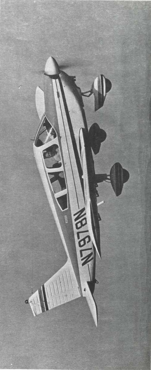
1 CHEROKEE 180 E OWNER'S HANDBOOK
2 WARNING The rudder pedals are suspended from a torque tube which extends across the fuselage. The pilot should become familiar with the proper positioning of his feet on the rudder pedals so as to avoid interference with the torque tube when moving the rudder pedals or operating the toe brakes

3 CHEROKEE 180 E PA This handbook for airplanes with serial nos through Owner's Handbook Piper Aircraft Corporation, Vero Beach, Florida U.S.A.
4 NOTICE THIS HANDBOOK IS NOT DESIGNED, NOR CAN ANY HANDBOOK SERVE, AS A SUBSTITUTE FOR ADEQUATE AND COMPETENT FLIGHT INSTRUCTION, OR KNOWLEDGE OF THE CURRENT AIRWORTHINESS DIRECTIVES, THE APPLICABLE FEDERAL AIR REGULATIONS, AND ADVISORY CIRCULARS. IT IS NOT INTENDED TO BE A GUIDE OF BASIC FLIGHT INSTRUCTION, NOR A TRAINING MANUAL. THE HANDBOOK IS DESIGNED: 1. TO HELP YOU OPERATE YOUR CHEROKEE WITH SAFETY AND CONFIDENCE. 2. TO MORE FULLY ACQUAINT YOU WITH THE BASIC PERFORMANCE AND HANDLING CHARACTERISTICS OF THE AIRPLANE. 3. TO MORE FULLY EXPLAIN YOUR CHEROKEE'S OPERATION THAN IS PERMISSIBLE TO SET FORTH IN THE AIRPLANE FLIGHT MANUAL. IF THERE IS ANY INCONSISTENCY BETWEEN THIS HANDBOOK AND THE AIRPLANE FLIGHT MANUAL APPROVED BY THE F.A.A., THE AIRPLANE FLIGHT MANUAL SHALL GOVERN. Revised text and illustrations shall be indicated by a black vertical line in the margin opposite the change. A line opposite the page number will indicate that material was relocated. Additional copies of this manual, Part No , may be obtained fromyour Piper Dealer. Published by PUBLICATIONS DEPARTMENT Piper Aircraft Corporation Issued: October 1969 Revised: January 1974
5
6
7 INDEX SECTION I Page Specifications: 1 Performance 1 Weights 2 Power Plant 2 Fuel and Oil 2 Baggage 2 Dimensions 3 Landing Gear 3 SECTION II Design Information: 5 Engine and Propeller 5 Structures 5 Landing Gear 6 Control Systems 7 Fuel System 7 Electrical System 9 Heating and Ventilating System 13 Cabin Features 13 SECTION III Operating Instructions:. 16 Preflight 16 Starting Engine 17 Warm-Up and Ground Check 19 Take-Off 19 Climb. 20 Stalls 20 Cruising 21 Approach and Landing 22 Stopping Engine
8 INDEX (cont) SECTION III (cont) Page Engine Power Loss 23 Mooring 24 Weight and Balance 24 Operating Tips 24 SECTION IV Emergency Procedures: 27 Introduction 27 Engine Power Loss During Takeoff 27 Engine Power Loss In Flight 28 Power Off Landing 29 Fire 30 Loss of Oil Pressure 31 Loss of Fuel Pressure 32 High Oil Temperature 32 Alternator Failure 33 Engine Roughness 33 Spins 34 Open Door 35 SECTION V Performance Charts: 36 Altitude Conversion Chart 36 Takeoff Distance vs Density Altitude 37 Rate of Climb vs Density Altitude 38 Range vs Density Altitude 39 True Airspeed and RPM vs Density Altitude 40 Landing Distance vs Density Altitude 41 Power Setting Table
9 INDEX (cont) SECTION VI Page General Maintenance: 43 Landing Gear Service 43 Brake Service 45 Tire Inflation 45 Care of Windshield and Windows 46 Battery Service 46 Fuel and Oil Requirements 47 Fuel System. 47 Care of Air Filter 48 Leveling and Rigging 48 Serial Number Plate
10
11 SECTION I SPECIFICATIONS Performance 1 Weights 2 Power Plant 2 Fuel and Oil 2 Baggage 2 Dimensions 3 Landing Gear
12
13 CHEROKEE "E" SECTION I SECTION I SPECIFICATIONS PERFORMANCE Published figures are for standard airplanes flown at gross weight under standard conditions at sea level, unless otherwise stated. Performance for a specific airplane may vary from published figures depending upon the equipment installed, the condition of engine, airplane and equipment, atmospheric conditions and piloting technique. Each performance figure below is subject to the same conditions as on the corresponding performance chart from which it is taken in the Performance Charts Section. Take-off Run (maximum effort, 25 flap) (ft) 720 Take-off over 50-ft barrier (maximum effort, 25 flap) (ft) 1625 Best Rate of Climb Speed (mph) 85 Rate of Climb (ft per min) 725 Service Ceiling (ft) 13,000 Absolute Ceiling (ft) 15,000 Top Speed (mph) 152 Optimum Cruising Speed (75% power, optimum altitude) (mph) 143 Cruising Range (75% power, optimum altitude) (mi) 725 Optimum Cruising Range (55% power, optimum altitude) (mi) 845 Stalling Speed (flaps down) (mph) 57 Stalling Speed (flaps up) (mph) 67 Landing Roll (flaps down) (ft) 600 Landing Roll over 50-ft barrier (ft)
14 SECTION I CHEROKEE "E" SPECIFICATIONS (cont): WEIGHTS Gross Weight (lbs) 2400 Empty Weight (Standard) (lbs) 1310 USEFUL LOAD (Standard) (lbs) 1090 POWER PLANT Engine (Lycoming) O-360-A4A Rated Horsepower 180 Rated Speed (rpm) 2700 Bore (in.) Stroke (in.) Displacement (cu in.) Compression Ratio 8.5:1 Dry Weight (lbs) 285 Propeller M76EMMS60 FUEL AND OIL Fuel Capacity (U.S. gal) 50 Oil Capacity (qts) 8 Fuel, Aviation Grade (min octane) 91/96 BAGGAGE Maximum Baggage (lbs) 200 Baggage Space (cu ft) 24 Baggage Door Size (in.) 20 x
15 CHEROKEE "E" SECTION I SPECIFICATIONS (cont): DIMENSIONS Wing Span (ft) 30 Wing Area (sq ft) 160 Wing Loading (lbs per sq ft) 15.0 Length (ft) 23.5 Height (ft) 7.3 Power Loading (lbs per hp) 13.3 LANDING GEAR Wheel Base (ft) 6.2 Wheel Tread (ft) 10 Tire Pressure (psi) Nose 24 Main 24 Tire Size Nose (4 ply rating) 6.00 x 6 Main (4 ply rating) 6.00 x
16 SECTION I CHEROKEE "E"
17 SECTION II DESIGN INFORMATION Engine and Propeller 5 Structures 5 Landing Gear 6 Control Systems 7 Fuel System 7 Electrical System 9 Heating and Ventilating System 13 Cabin Features
18
19 CHEROKEE "E" SECTION II SECTION II DESIGN INFORMATION ENGINE AND PROPELLER The Cherokee "E" is powered by a Lycoming O-360-A4A four cylinder, direct drive, horizontally opposed engine rated at 180 HP at 2700 RPM. It is furnished with a starter, 60 ampere 12 volt alternator, shielded ignition, vacuum pump drive, fuel pump, and a dry, automotive type carburetor air filter. The exhaust system is of the cross-over type to reduce back pressure and improve performance. It is made entirely from stainless steel and is equipped with dual mufflers. A heater shroud around the mufflers is provided to supply heat for the cabin and windshield defrosting. The Sensenich M76EMMS60 fixed-pitch propeller is made from a one-piece alloy forging. STRUCTURES All structures are of aluminum alloy construction and are designed to ultimate load factors well in excess of normal requirements. All exterior surfaces are primed with etching primer and painted with acrylic enamel. The wings are attached to each side of the fuselage by inserting the butt ends of the respective main spars into a spar box carry-through which is an integral part of the fuselage structure, providing in effect a continuous main spar with splices at each side of the fuselage. There are also fore and aft attachments at
20 SECTION II CHEROKEE "E" the rear spar and at an auxiliary front spar. The wing airfoil section is a laminar flow type, NACA with the maximum thickness about 40% aft of the leading edge. This permits the main spar carry-through structure to be located under the rear seat providing unobstructed cabin floor space ahead of the rear seat. LANDING GEAR The three landing gears use a Cleveland 6.00 x 6 wheel, the main wheels being provided with Cleveland single disc hydraulic brake assemblies, No All wheels use 6.00 x 6 four ply tires with tubes. The nose gear is steerable through a 44 degree arc by use of the rudder pedals. A spring device is incorporated in the rudder pedal torque tube assembly to aid in rudder centering and to provide rudder trim. The nose gear steering mechanism also incorporates a hydraulic shimmy dampener. The three struts are of the air-oil type, with the normal extension being 3.25 inches for the nose gear and 4.50 inches for the main gear. The standard brake system for the Cherokee consists of a hand lever and master cylinder which is located below and behind the left center of the instrument sub-panel. The brake fluid reservoir is installed on the top left front face of the firewall. The parking brake is incorporated in the master cylinder and is actuated by pulling back on the brake lever, depressing the knob attached to the handle and releasing the brake lever. To release the parking brake, pull back on the lever to disengage the catch mechanism and allow the handle to swing forward. Optional toe brakes are available to supplement the standard hand lever and parking brake system
21 CHEROKEE "E" SECTION II CONTROL SYSTEMS Dual controls are provided as standard equipment with a cable system used between the controls and the surfaces. The horizontal tail is of the Flying Tail type (stabilator), with a trim tab mounted on the trailing edge of the stabilator to reduce the control system forces. This tab is actuated by a control wheel on the floor between the front seats. The stabilator provides extra stability and controllability with less size, drag and weight than conventional tail surfaces. The ailerons are provided with a differential action which tends to reduce adverse yaw in turning maneuvers, and which also reduces the amount of coordination required in normal turns. A rudder trim adjustment is mounted on the right side of the pedestal below the throttle quadrant and permits directional trim as needed in flight. The flaps are manually operated, balanced for light operating forces and spring-loaded to return to the up position. A pastcenter lock incorporated in the actuating linkage holds the flap when it is in the up position so that it may be used as a step on the right side. The flap will not support a step load except when in the full up position, so it must be completely retracted when used as a step. The flaps have three extended positions: 10, 25 and 40 degrees. FUEL SYSTEM Fuel is stored in two twenty-five gallon tanks which are secured to the leading edge structure of each wing by screws and nut plates. This allows easy removal for service or inspection. An auxiliary electric fuel pump is provided in case of failure of the engine-driven pump. The electric pump should be on for all take-offs and landings, and when switching tanks. The pump switch is located in the switch panel above the throttle quadrant. Each tank has an individual quick drain located at the bottom, inboard rear corner, and should be drained to check for
22 SECTION II CHEROKEE "E" CARBURETOR FUEL PRESSURE GAUGE FUEL QUANTITY GAUGES VENT VENT ENGINE FUEL PUMP ELECTRIC FUEL PUMP VENT DRAIN GASCOLATOR PRIMER FUEL SELECTOR VALVE LEFT TANK RIGHT TANK DRAIN DRAIN FUEL SYSTEM SCHEMATIC

23 CHEROKEE "E" SECTION II water before each flight. The fuel strainer, which is also equipped with a quick drain, is located on the front lower left corner of the firewall. This strainer should be drained regularly to check for water or sediment accumulation. Fuel quantity and pressure are indicated on gauges located in a cluster on the left side of the instrument panel. ELECTRICAL SYSTEM The electrical system includes a 14 volt, 60 amp alternator, battery, voltage regulator, overvoltage relay and master switch relay. The battery is mounted in a stainless steel box immediately aft of the baggage compartment. The regulator and overvoltage relay are located on the forward left side of the fuselage behind the instrument panel. Electrical switches are located on the right center instrument panel, and the circuit breakers are located on the lower right instrument panel. A rheostat-switch on the left side of the switch panel controls the navigation lights and the dome instrument light. It also dims the dome light. The similar switch on the right side controls and dims the panel lights. Circuit Breaker Panel
24 SECTION II CHEROKEE "E" Standard accessories include a starter, electric fuel pump, stall warning indicator, cigar lighter,fuel gauge and ammeter. The navigation lights, anti-collision light, landing light, instrument lighting and cabin dome light are optional. Circuits will handle an entire complement of communications and navigational equipment Ṫhe alternator system offers many advantages over the generator system both in operation and maintenance. The main advantage is full electrical power output at lower engine RPM. This is a great improvement for radio and electrical equipment operation. Since the alternator output is available at all times, the battery will be charging for a greater percentage of use. This will make cold-morning starting easier. The words "master switch" used hereafter in this manual indicate both sides of the switch, battery side "BAT" and alternator side "ALT" are to be depressed simultaneously to Off or On as directed. Unlike previous generator systems, the ammeter does not indicate battery discharge; rather it displays in amperes the load placed on the alternator. With all electrical equipment off (except master switch) the ammeter will be indicating the amount of charging current demanded by the battery. As each item of electrical equipment is turned on, the current will increase to a total appearing on the ammeter. This total includes the battery. The maximum continuous load for night flight, with radios on, is about 30 amperes. This 30 ampere value, plus approximately two amperes for a fully charged battery, will appear continuously under these flight conditions. The amount of current shown on the ammeter will tell immediately if the alternator system is operating normally, as the amount of current shown should equal the total amperage drawn by the equipment which is operating. If no output is indicated on the ammeter during flight, reduce the electrical load by turning off all unnecessary electrical equipment. Check both 5 ampere field breaker and 60 ampere output breaker and reset if open. If neither circuit breaker is open, turn off the "ALT" switch for 1 second to reset the overvoltage
25 CHEROKEE "E" SECTION II ELECTRICAL SYSTEM
26 SECTION II CHEROKEE "E" Cherokee Cabin Heat, Defroster, Fresh Air HEATING AND VENTILATING SYSTEM
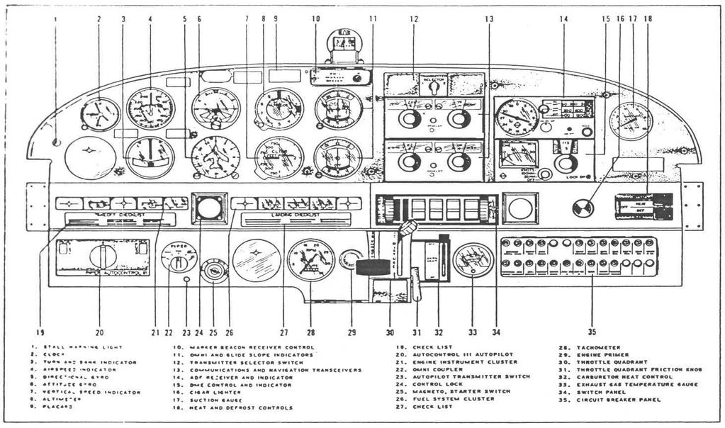
27 CHEROKEE "E" SECTION II relay. If ammeter continues to indicate no output, maintain minimum electrical load and terminate flight as soon as practical. Maintenance on the alternator should prove to be a minor factor. Should service be required, contact the local Piper Dealer. HEATING AND VENTILATING SYSTEM Heat for the cabin interior and the defroster system is provided by a heater muff attached to the exhaust system. The amount of heat desired can be regulated with the controls located on the far right side of the instrument panel. Fresh air inlets are located in the leading edge of the wing at the intersection of the tapered and straight sections. A large adjustable outlet is located on the side of the cabin near the floor at each seat location. Cabin air is exhausted through an outlet located below the rear seat. CABIN FEATURES The instrument panel of the Cherokee is designed to accommodate the customary advanced flight instruments and the normally required power plant instruments. The Artifical Horizon and Directional Gyro are vacuum operated through use of a vacuum pump installed on the engine, while the Turn and Bank instrument is electrically operated. Above the Attitude Gyro are two lights which indicate high or low vacuum. A natural separation of the flight group and the power group is provided by placing the flight group in the upper instrument panel and the power group in the center and lower instrument panels. The cabin interior includes a pilot storm window, two sun visors, ash trays, two map pockets, and pockets on the backs of each front seat. The front seats are adjustable fore and aft for pilot-passenger comfort and ease of entry and exit. Arm rests are also provided for the front seats. The 24 cubic foot baggage area may be reached from the cabin or through a large 20 x 22 inch outside door
28
29 CHEROKEE "E" SECTION II NOTES
30
31 SECTION III OPERATING INSTRUCTIONS Preflight 16 Starting Engine 17 Warm-Up and Ground Check 19 Take-Off 19 Climb 20 Stalls 20 Cruising 21 Approach and Landing 22 Stopping Engine 23 Engine Power Loss 23 Mooring 24 Weight and Balance 24 Operating Tips
32
33 CHEROKEE "E" SECTION III SECTION III OPERATING INSTRUCTIONS PREFLIGHT 1. Master switch and ignition OFF. 2. a. Check for external damage and operational interference of control surfaces or hinges. b. Insure that wings and control surfaces are free of snow, ice or frost. 3. a. Visually check fuel supply and secure caps
34 SECTION III CHEROKEE "E" b. Drain fuel tank sumps (two). c. Drain fuel system sump (left side of aircraft). d. Check that fuel system vents are open. e. Check main landing gear shock struts for proper inflation (approximately 4.50 inches showing). f. Check tires for cuts, wear and proper inflation. 4. a. Check windshield for cleanliness. b. Check propeller and spinner for defects or nicks. c. Check for obvious fuel or oil leaks. d. Check oil level (insure dipstick is properly seated). e. Check cowling and inspection covers for security, f. Check nose wheel tire for inflation and wear. g. Check nose gear shock strut for proper inflation (approximately 3.25 inches showing). h. Check for foreign matter in air inlet. 5. a. Stow tow-bar and control locks if used. b. Check baggage for storage and security. c. Close and secure the baggage compartment door. 6. a. Upon entering airplane remove and stow control column lock pin in side pocket. Check that all primary flight controls operate properly. b. Close and secure cabin door. c. Check that required papers are in order and in the airplane. d. Fasten safety belts. STARTING ENGINE 1. Set parking brake ON. 2. Set the carburetor heat control in the full COLD position. 3. Select the desired tank with fuel selector valve. Starting Engine When Cold: 1. Open throttle approximately 1/4 inch. 2. Turn the master switch ON. 3. Turn the electric fuel pump ON. 4. Move the mixture control to FULL RICH
35 CHEROKEE "E" SECTION 5. Engage the starter by rotating magneto switch clockwise and pressing in. 6. When the engine fires, advance throttle to desired setting. If the engine does not fire within five to ten seconds, disengage starter and prime with one to three strokes of the priming pump. Repeat the starting procedure. Starting Engine When Hot: 1. Open the throttle approximately 1/2 inch. 2. Turn the master switch ON. 3. Turn the electric fuel pump ON. 4. Put mixture control in IDLE CUT-OFF. 5. Engage the starter by rotating magneto switch clockwise and pressing in. When the engine fires, advance the mixture control and move the throttle to desired setting. Starting Engine When Flooded: 1. Open the throttle full. 2. Turn the master switch ON. 3. Turn the electric fuel pump OFF. 4. Put mixture control in IDLE CUT-OFF. 5. Engage the starter by rotating magneto switch clockwise and pressing in. When the engine fires, advance the mixture control and retard the throttle. When the engine is firing evenly, advance the throttle to 800 RPM. If oil pressure is not indicated within thirty seconds, stop the engine and determine the trouble. In cold weather it will take a few seconds longer to get an oil pressure indication. If the engine has failed to start, refer to the "Lycoming Operating Handbook, Engine Troubles and Their Remedies." Starter manufacturers recommend that cranking periods be limited to thirty seconds with a two minute rest between cranking periods. Longer cranking periods will shorten the life of the starter
36 SECTION V PERFORMANCE CHARTS Altitude Conversion Chart 36 Takeoff Distance vs Density Altitude 37 Rate of Climb vs Density Altitude 38 Range vs Density Altitude 39 True Airspeed and RPM vs Density Altitude 40 Landing Distance vs Density Altitude 41 Power Setting Table
37 CHEROKEE "E" SECTION III The take-off technique is conventional for the Cherokee. The tab should be set slightly aft of neutral, with the exact setting determined by the loading of the aircraft. Allow the airplane to accelerate to 50 to 60 MPH, then ease back on the wheel enough to let the airplane fly itself off the ground. Premature raising of the nose, or raising it to an excessive angle will result in a delayed take-off. After take-off let the aircraft accelerate to the desired climb speed by lowering the nose slightly. Take-offs are normally made with flaps up. However, for short field take-offs, and for take-offs under difficult conditions such as deep grass or on a soft surface, distances can be reduced appreciably by lowering flaps to 25. CLIMB The best rate of climb at gross weight will be obtained at 85 MPH. The best angle of climb may be obtained at 74 MPH. At lighter than gross weight these speeds are reduced somewhat. For climbing en route a speed of 100 MPH is recommended. This will produce better forward speed and increased visibility over the nose during the climb. STALLS All controls are effective at speeds down through the stalling speed, and stalls are gentle and easily controlled. Stall speed chart on following page is at gross weight. Stall speeds at lower weights will be correspondingly less
38 SECTION III CHEROKEE "E" Angle of Bank STALL SPEED TABLE Flaps MPH 59 MPH 65 MPH 81 MPH Flaps Retracted 67 MPH 69 MPH 77 MPH 95 MPH Power Off - Gross Weight 2400 lbs. CRUISING The cruising speed is determined by many factors including power setting, altitude, temperature, loading and equipment installed on the airplane. The normal cruising power is 75% of the rated horsepower of the engine. True airspeeds which may be obtained at various altitudes and power settings can be determined from the charts in Section V of this handbook. Use of the mixture control in cruising flight reduces fuel consumption significantly, especially at higher altitudes. The mixture should be leaned during cruising operation above 5000 feet altitude and at pilot's discretion at lower altitudes when 75% power or less is being used. If any doubt exists as to the amount of power being used, the mixture should be in the FULL RICH position for all operations under 5000 feet. To lean the mixture, pull the mixture control until the engine becomes rough, indicating that the lean mixture limit has been reached in the leaner cylinders. Then enrich the mixture by pushing the control towards the instrument panel until engine operation becomes smooth. The fuel flow meter will give a close approximation of the fuel being consumed. If the airplane is equipped with the optional exhaust gas
39 CHEROKEE "E" SECTION III temperature (EGT) gauge, a more accurate means of leaning is available to the pilot. For best power mixture, lean the mixture until the peak EGT is reached, then enrich the mixture until the temperature drops a minimum of 25 F. For best economy mixture, lean until the peak EGT is reached and continue to lean until the temperature drops a minimum of 25 F. Do not lean above 75% power. In order to keep the airplane in best lateral trim during cruising flight, the fuel should be used alternately from each tank. It is recommended that one tank be used for one hour after take-off, then the other tank be used for two hours, then return to the first tank, which will have approximately one and one half hours of fuel remaining if the tanks were full at take-off. The second tank will contain approximately one half hour of fuel. Do not run tanks completely dry in flight. APPROACH AND LANDING Before landing check list: 1. Fuel - on proper tank 2. Electric fuel pump - ON 3. Mixture - set 4. Flaps - set (115 MPH MAX) 5. Seat belts - fastened The airplane should be trimmed to an approach speed of about 85 MPH with flaps up. The flaps can be lowered at speeds up to 115 MPH, if desired, and the approach speed reduced 3 MPH for each additional notch of flaps. Carburetor heat should not be applied unless there is an indication of carburetor icing, since the use of carburetor heat causes a reduction in power which may be critical in case of a go-around. Full throttle operation with heat on is likely to cause detonation. The amount of flap used during landings and the speed of the aircraft at contact with the runway should be varied according to the landing surface and conditions of wind and airplane loading
40 SECTION III CHEROKEE "E" It is generally good practice to contact the ground at minimum possible safe speed consistent with existing conditions. Normally, the best technique for short and slow landings is to use full flap and enough power to maintain the desired airspeed and approach flight path. Reduce the airspeed during flare out and contact the ground close to stalling speed. After ground contact hold the nose wheel off as long as possible. As the airplane slows down, drop the nose and apply the brakes. There will be less chance of skidding the tires if the flaps are retracted before applying the brakes. Braking is most effective when back pressure is applied to the control wheel, putting most of the airplane weight on the main wheels. In high wind conditions, particularly in strong crosswinds, it may be desirable to approach the ground at higher than normal speeds with partial or no flaps. STOPPING ENGINE At the pilot's discretion, the flaps should be raised and the electric fuel pump turned off. After parking, the radios should be turned off and the engine stopped by pulling the mixture control to idle cut-off. The throttle should be left full aft to avoid engine vibration while stopping. Then the magneto and master switches should be turned off and the parking brake set. ENGINE POWER LOSS The most common cause of engine power loss is mismanagement of the fuel. Therefore, the first step to take after engine power loss is to move the fuel selector valve to the tank not being used. This will often keep the engine running even if there is no apparent reason for the engine to stop on the tank being used
41 CHEROKEE "E" SECTION III If changing to another tank does not restore the engine: 1. Check fuel pressure and turn on electric fuel pump if off. 2. Push mixture control to full "RICH." 3. Check ignition switch. Turn to best operating magneto - left, right, or both. MOORING The Cherokee should be moved on the ground with the aid of the nose wheel tow-bar provided with each plane and secured in the baggage compartment. Tie down ropes may be secured to rings provided under each wing and to the tail skid. The aileron and stabilator controls should be secured by utilization of the control column lock pin in the left hand wheel control column. The rudder is held in position by its connections to the nose wheel steering and normally does not have to be secured. The flaps are locked when in the full up position and should be left retracted. WEIGHT AND BALANCE It is the responsibility of the owner and pilot to determine that the airplane remains within the allowable weight vs. center of gravity envelope while in flight. For weight and balance data see the Airplane Flight Manual and Weight and Balance form supplied with each airplane. OPERATING TIPS The following Operating Tips are of particular value in the operation of the Cherokee. 1. Learn to trim for take-off so that only a very light back pressure on the wheel is required to lift the airplane off the
42 SECTION III CHEROKEE "E" ground. 2. The best speed for take-off is about 60 MPH under normal conditions. Trying to pull the airplane off the ground at too low an airspeed decreases the controllability of the airplane in event of engine failure. 3. Flaps may be lowered at airspeeds up to 115 MPH. To reduce flap operating loads, it is desirable to have the airplane at a slower speed before extending the flaps. 4. Before attempting to reset any circuit breaker, allow a two to five minute cooling off period. 5. Before starting the engine, check that all radio switches, light switches, and the pitot heat switch are in the off position so as not to create an overloaded condition when the starter is engaged. 6. The overvoltage relay is provided to protect the electronics equipment from a momentary overvoltage condition (approximately 16.5 volts and up), or a catastrophic regulator failure. In the event of a momentary condition, the relay will open and the ammeter will indicate "0" output from the alternator. The relay may be reset by switching the''alt''switch to "OFF" for approximately one second and then returning the "ALT" switch to "ON." 7. The vacuum gauge is provided to monitor the pressure available to assure the correct operating speed of the vacuum driven gyroscopic flight instruments. It also monitors the condition of the common air filter by measuring the flow of air thru the filter. If the vacuum gauge does not register 5" +.1" Hg at 2000 RPM, the following items should be checked before flight: a. Common air filter, could be dirty or restricted. b. Vacuum lines could be collapsed or broken. c. Vacuum pump, worn. d. Vacuum regulator, not adjusted correctly. The pressure, even though set correctly, can read lower under two conditions: (1) Very high altitude, above feet, (2) Low engine RPM usually on approach or during training maneuvers. This is normal and should not be considered a malfunction
43 CHEROKEE "E" SECTION III 8. The shape of the wing fuel tanks is such that in certain maneuvers the fuel may move away from the tank outlet. If the outlet is uncovered, the fuel flow may be interrupted and a temporary loss of power may result. Pilots can prevent inadvertent uncovering of the outlet by avoiding maneuvers which could result in uncovering the outlet. Running turning takeoffs should be avoided as fuel flow interruption may occur if tank in use is not full. Prolonged slips or skids in any pitch attitude or other unusual maneuvers which could cause uncovering of the fuel outlet must be avoided when tank being used is not full. 9. The rudder pedals are suspended from a torque tube which extends across the fuselage. The pilot should become familiar with the proper positioning of his feet on the rudder pedals so as to avoid interference with the torque tube when moving the rudder pedals or operating the toe brakes. 10. Anti-collision lights should not be operating when flying through overcast and clouds since reflected light can produce spacial disorientation. Do not operate strobe lights when taxiing in the vicinity of other aircraft
44
45 SECTION IV EMERGENCY PROCEDURES Introduction 27 Engine Power Loss During Takeoff 27 Engine Power Loss In Flight 28 Power Off Landing. 29 Fire 30 Loss of Oil Pressure 31 Loss of Fuel Pressure 32 High Oil Temperature 32 Alternator Failure 33 Engine Roughness 33 Spins 34 Open Door
46
47 CHEROKEE"E" SECTION IV SECTION IV EMERGENCY PROCEDURES INTRODUCTION This section contains procedures that are recommended if an emergency condition should occur during ground operation, takeoff, or in flight. These procedures are suggested as the best course of action for coping with the particular condition described, but are not a substitute for sound judgement and common sense. Since emergencies rarely happen in modern aircraft, their occurrence is usually unexpected, and the best corrective action may not always be obvious. Pilots should familiarize themselves with the procedures given in this section and be prepared to take appropriate action should an emergency arise. Most basic emergency procedures, such as power off landings, are a normal part of pilot training. Although these emergencies are discussed herein, this information is not intended to replace such training, but only to provide a source of reference and review, and to provide information on procedures which are not the same for all aircraft. It is suggested that the pilots review standard emergency procedures periodically to remain proficient in them. ENGINE POWER LOSS DURING TAKEOFF The proper action to be taken if loss of power occurs during takeoff will depend on circumstances. 1. If sufficient runway remains for a normal landing, land straight ahead. 2. If insufficient runway remains, maintain a safe airspeed and make only a shallow turn if necessary to avoid obstructions. Use of flaps depends on circumstances. Normally, flaps should be fully extended for touchdown
48 SECTION IV CHEROKEE "E" 3. If you have gained sufficient altitude to attempt a restart, proceed as follows: a. MAINTAIN SAFE AIRSPEED b. FUEL SELECTOR - SWITCH TO ANOTHER TANK CONTAINING FUEL c. ELECTRIC FUEL PUMP - CHECK ON d. MIXTURE - CHECK RICH e. CARBURETOR HEAT - ON NOTE If engine failure was caused by fuel exhaustion, power will not be regained after tanks are switched until empty fuel lines are filled, which may require up to ten seconds. If power is not regained, proceed with the POWER OFF LANDING procedure. ENGINE POWER LOSS IN FLIGHT Complete engine power loss is usually caused by fuel flow interruption, and power will be restored shortly after fuel flow is restored. If power loss occurs at low altitude, the first step is to prepare for an emergency landing (See POWER OFF LANDING). Maintain an airspeed of at least 82 MPH IAS, and if altitude permits, proceed as follows: 1. Fuel Selector - Switch to another tank containing fuel 2. Electric Fuel Pump - On 3. Mixture - Rich 4. Carburetor Heat - On 5. Engine Gauges - Check for an indication of the cause of power loss 6. Primer - Check Locked 7. If no fuel pressure is indicated, check tank selector position to be sure it is on a tank containing fuel
49 CHEROKEE "E" SECTION IV When power is restored: 8. Carburetor Heat - Off 9. Electric Fuel Pump - Off If the above steps do not restore power, prepare for an emergency landing. If time permits: 1. Ignition Switch - "L" then "R" then back to "BOTH." 2. Throttle and Mixture - Different settings. (This may restore power if problem is too rich or too lean a mixture, or a partial fuel system restriction.) 3. Try another fuel tank. (Water in the fuel could take some time to be used up, and allowing the engine to windmill may restore power. If power loss is due to water, fuel pressure indications will be normal.) NOTE If engine failure was caused by fuel exhaustion, power will not be regained after tanks are switched until empty fuel lines are filled, which may require up to ten seconds. If power is not restored, proceed with POWER OFF LANDING procedures. POWER OFF LANDING If loss of power occurs at altitude, trim the aircraft for best gliding angle, 82 MPH IAS, and look for a suitable field. If measures taken to restore power are not effective, and if time permits, check your charts for airports in the immediate vicinity; it may be possible to land at one if you have sufficient altitude. If possible, notify the FAA by radio of your difficulty and intentions. If another pilot or passenger is aboard, let them help
50 SECTION IV CHEROKEE "E" When you have located a suitable field, establish a spiral pattern around this field. Try to be at 1000 feet above the field at the downwind position, to make a normal approach. Excess altitude may be lost by widening your pattern, using flaps or slipping, or a combination of these. Touchdown should normally be made at the lowest possible airspeed, with full flaps. When committed to landing: 1. Ignition - Off 2. Master Switch - Off 3. Fuel Selector - Off 4. Mixture - Idle Cut-Off 5. Seat belt - Tight FIRE The presence of fire is noted through smoke, smell, and heat in the cabin. It is essential that the source of the fire be promptly identified through instrument readings, character of the smoke, or other indications, since the action to be taken differs somewhat in each case. Source of fire - Check 1. Electrical Fire (smoke in cabin): a. Master Switch - Off b. Vents - Open c. Cabin Heat - Off d. Land as soon as possible
51 CHEROKEE "E" SECTION IV 2. Engine Fire In Flight: a. Fuel Selector - Off b. Throttle - Closed c. Mixture - Idle cut-off d. Heater - Off (In all cases of fire) e. Defroster - Off (In all cases of fire) f. If terrain permits, land immediately. The possibility of an engine fire in flight is extremely remote. The procedure given above is general and pilot judgment should be the deciding factor for action in such an emergency. 3. Engine Fire During Start: a. If engine has not started (1) Mixture - Idle cut-off (2) Throttle - Open (3) Turn engine with starter (This is an attempt to pull the fire into the engine.) b. If engine has already started and is running, continue operating to try pulling the fire into the engine. c. In either case stated a. and b., if the fire continues longer than a few seconds, the fire should be extinguished by the best available external means. d. If external fire extinguishing is to be applied: (1) Fuel Selector - Off (2) Mixture - Idle cut-off Engine fires during start are usually the result of over priming. The procedure above is designed to draw the excess fuel back into the induction system. LOSS OF OIL PRESSURE Loss of oil pressure may be either partial or complete. A partial loss of oil pressure usually indicates a malfunction in the oil pressure regulating system, and a landing should be made as soon as possible to investigate the cause and prevent engine damage
52 SECTION IV CHEROKEE "E" A complete loss of oil pressure indication may signify oil exhaustion or may be the result of a faulty gauge. In either case, proceed toward the nearest airport, and be prepared for a forced landing. If the problem is not a pressure gauge malfunction, the engine may stop suddenly. Maintain altitude until such time as a dead stick landing can be accomplished. Don't change power settings unnecessarily, as this may hasten complete power loss. Depending on the circumstances, it may be advisable to make an off airport landing while power is still available, particularly if other indications of actual oil pressure loss, such as sudden increases in temperatures, or oil smoke, are apparent, and an airport is not close. If engine stoppage occurs, proceed to POWER OFF LANDING. LOSS OF FUEL PRESSURE 1. Electric Boost Pump - On 2. Fuel Selector - Check on Full Tank If problem is not an empty fuel tank, land as soon as practical, and have engine-driven fuel pump checked. HIGH OIL TEMPERATURE An abnormally high oil temperature indication may be caused by a low oil level, an obstruction of the oil cooler, damaged or improper baffle seals, a defective gauge, or other causes. Land as soon as practical at an appropriate airport and have the cause investigated. A steady, rapid rise in oil temperature is a sign of trouble. Land at the nearest airport and let a mechanic investigate the problem. Watch the oil pressure gauge for an accompanying loss of pressure
53 CHEROKEE "E" SECTION IV ALTERNATOR FAILURE Loss of alternator output is detected through a zero reading on the ammeter. Before executing the following procedure, insure that the reading is zero and not merely low by actuating an electrically powered device, such as the landing light. If no increase in the ammeter reading is noted, alternator failure can be assumed. 1. Reduce Electrical Load. 2. Alternator Circuit Breakers - Check 3. "Alt" Switch - Off (for 1 second), Then On If the ammeter continues to indicate no output, or alternator will not stay reset, turn off "Alt" switch, maintain minimum electrical load and land as soon as practical. All electrical load is being supplied by the battery. ENGINE ROUGHNESS Engine roughness is usually due to carburetor icing, which is indicated by a drop in RPM, and may be accompanied by a slight loss of airspeed or altitude. If too much ice is allowed to accumulate, restoration of full power may not be possible; therefore, prompt action is required. Carburetor Heat - On (See Note) RPM will decrease slightly and roughness will increase. Wait for a decrease in engine roughness or an increase in RPM, indicating ice removal. If no change in approximately one minute, return carburetor heat to COLD. If the engine is still rough, try steps below. 1. Mixture - Adjust for maximum smoothness. Engine will run rough if too rich or too lean. 2. Electric Fuel Purrp - On 3. Fuel Selector - Change tanks to see if fuel contamination is the problem. 4. Engine Gauges - Check for abnormal readings. If any gauge readings are abnormal, proceed accordingly
54 SECTION IV CHEROKEE "E" 5. Magneto Switch - "L" then "R," then back to "BOTH." If operation is satisfactory, on either magneto, proceed on that magneto at reduced power, with mixture full rich, to a landing at the first available airport. If roughness persists, prepare for a precautionary landing at pilot's discretion. NOTE Partial carburetor heat may be worse than no heat at all, since it may partially melt the ice, which will refreeze in the intake system. When using carburetor heat, therefore, always use full heat and when ice is removed, return the control to the full cold position. SPINS Intentional spins are prohibited in this aircraft. If a spin is inadvertently entered, immediately use the following recovery procedures: 1. THROTTLE - IDLE 2. RUDDER - FULL OPPOSITE TO DIRECTION OF ROTATION 3. CONTROL WHEEL - FULL FORWARD 4. RUDDER - NEUTRAL (WHEN ROTATION STOPS) 5. CONTROL WHEEL - AS REQUIRED TO SMOOTHLY REGAIN LEVEL FLIGHT ATTITUDE
55 CHEROKEE "E" SECTION IV OPEN DOOR The cabin door on the Cherokee is double latched, so the chance of its springing open in flight at both the top and bottom is remote. However, should you forget the upper latch, or not fully engage the lower latch, the door may spring partially open. This will usually happen at takeoff or soon afterward. A partially open door will not affect normal flight characteristics, and a normal landing can be made with the door open. If both upper and lower latches open, the door will trail slightly open, and airspeed will be reduced slightly. To close a door in flight, proceed as follows: 1. Slow aircraft to 100 MPH IAS 2. Cabin Vents - Close 3. Storm Window - Open 4. If upper latch is open - latch. If lower latch is open - open top latch, push door further open, and then close rapidly. Latch top latch. A slip in the direction of the open door will assist in latching procedure
56
57 SECTION V PERFORMANCE CHARTS Altitude Conversion Chart 36 Takeoff Distance vs Density Altitude 37 Rate of Climb vs Density Altitude 38 Range vs Density Altitude 39 True Airspeed and RPM vs Density Altitude 40 Landing Distance vs Density Altitude 41 Power Setting Table
58
59 CHEROKEE "E" SECTION V PA PIPER CHEROKEE THIS CHART SHOULD BE USED TO DETERMINE DENSITY ALTITUDE FROM EXISTING TEMPERATURE AND PRESSURE ALTITUDE CONDITIONS FOR USE WITH PERFORMANCE CHARTS DENSITY ALTITUDE FT SL TEMPERATURE F
60 SECTION V CHEROKEE"E" PA-28-18O PIPER CHEROKEE MAXIMUM EFFORT 25 FLAPS PAVED LEVEL DRY RUNWAY BENSfTY ALTITUDE FT TAKE Of F DISTANCE FT
61 CHEROKEE "E" SECTION V PA-28-18O PIPER CHEROKEE LBS. GROSS WT DENSITY ALTITUDE FT RATE OF CLIMB FT/MIN
62 SECTION V CHEROKEE "E" PA PIPER CHEROKEE 2400 LBS GR0SS WT 50 GAL. FUEL FULL TANKS LEAN MIXTURE DENSITY ALTITUDE - FT RANGE (STATUTE MILES)
63 CHEROKEE "E" SECTION V PA-28-18O PIPER CHEROKEE MIXTURE LEANED TO MAX. RPM 2400 LBS. GROSS WT. i ENTER WITH RPM AND ALTITUDE AND ESTABLISH POINT A. THIS GIVES PERCENT OF POWER. READ HORIZONTALLY TO POINT B AT THE SAME ALTITUDE AND PERCENT OF POWER. READ VERTICALLY DOWN TO TRUE AIRSPEED POINT C. DENSITY ALTITUDE FT ENGINE RPM TRUE AIRSPEED MPH
64 SECTION V CHEROKEE "E" PA PIPER CHEROKEE 2400 LBS GROSS WT DENSITY ALTITUDE - FT LANDING DISTANCE FT
65 CHEROKEE"E" SECTION V Power Setting Table-Lycoming Model Series, 180 HP Engine Press. Alt SL 1,000 2,000 3,000 4,000 5,000 6,000 7,000 8,000 9,000 10,000 11,000 Std Alt Temp F HP 60% Power RPM HP 65% Power RPM HP 70% Power RPM HP 75% Power RPM , Press. Alt SL 1,000 2,000 3,000 4,000 5,000 6,000 7,000 8,000 9,000 10,000 11,000 12,
66
67 SECTION VI GENERAL MAINTENANCE Landing Gear Service 43 Brake Service 45 Tire Inflation 45 Care of Windshield and Windows 46 Battery Service 46 Fuel and Oil Requirements 47 Fuel System 47 Care of Air Filter 48 Leveling and Rigging 48 Serial Number Plate
68
69 CHEROKEE "E" SECTION VI SECTION VI GENERAL MAINTENANCE This section of the Cherokee "E" Handbook contains information which pertains to minor maintenance of the airplane. For further maintenance assistance refer to the Service Manual for this airplane. Any complex repairs or modification should be accomplished by a Piper Certified Service Center or equivalent. LANDING GEAR SERVICE The main wheels are Cleveland Aircraft Products, Model #40-86, with Cleveland single disk hydraulic brake assemblies, Model # The nose wheel is a Cleveland Aircraft Products, Model # All wheels use a 6.00 x 6, four ply rating, type III tire with tube. Main wheels are easily removed by taking off the hub cap, axle nut, and the two bolts holding the brake segment in place, after which the wheel slips easily from the axle. Tires are demounted from the wheels by deflating the tire, removing the three through-bolts, and separating the wheel halves. Landing gear oleo struts should be checked for proper strut exposures and fluid leaks. The required extensions for the strut when under normal static load (empty weight of airplane plus full fuel and oil) is 3.25 inches for the nose gear and 4.50 inches for the main gear. Should the strut exposure be below that required, it should be determined whether air or oil is required by first raising the airplane on jacks. Depress the valve core to allow
70 SECTION VI CHEROKEE "E" air to escape from the strut housing chamber. Remove the filler plug and slowly raise the strut to full compression. If the strut has sufficient fluid it will be visible up to the bottom of the filler plug hole and will then only require proper inflation. Should fluid be below the bottom of the filler plug hole, oil should be added. Replace the plug with valve core removed, attach a clear plastic hose to the valve strut of the filler plug and submerge the other end in a container of hydraulic fluid (MIL-H-5606). Fully compress and extend the strut several times thus drawing fluid from the container and expelling air from the strut chamber. To allow the fluid to enter the bottom chamber of the main gear strut housing, the torque link assembly must be disconnected to let the strut be extended a minimum of 10 inches. (The nose gear torque links need not be disconnected.) Do not allow the strut to extend more than 12 inches. When air bubbles cease to flow through the hose, compress the strut fully and again check fluid level. Reinstall the valve core and filler plug, and the main gear torque links, if disconnected. With fluid in the strut housing at the correct level, attach a strut pump to the air valve and with the airplane on the ground, inflate the oleo strut to the correct height. In jacking the Cherokee for landing gear or other service, a jack kit (available through Piper Dealers or Distributors) should be used. This kit consists of two hydraulic jacks and a tail stand. At least 250 pounds of ballast should be placed on the base of the tail stand before the airplane is jacked up. The hydraulic jacks should be placed under the jack points on the bottom of the wing and the airplane jacked up until the tail skid is at the right height to attach the tail stand. After attaching the tail stand and adding the ballast, the jacking may be continued until the aircraft is at the height desired. The steering arms from the rudder pedals to the nose wheel are adjusted at the rudder pedals or at the nose wheel by turning in or out the threaded rod end bearings. Adjustment is normally accomplished at the forward end of the rods and should be done in such a way that the nose wheel is in line with the fore and aft axis of the plane when the rudder pedals and rudder are centered
71 CHEROKEE "E" SECTION VI Alignment of the nose wheel can be checked by pushing the airplane back and forth with the rudder centered to determine that the plane follows a perfectly straight line. The turning arc of the nose wheel is 22 degrees in either direction and factory adjusted at stops on the bottom of the forging. The turning radius of the nose wheel is 17 feet. The steering arm stops should be carefully adjusted so that the nose wheel reaches its full travel just after the rudder hits its stops. This guarantees that the rudder will be allowed to move through its full travel. BRAKE SERVICE The brake system is filled with MIL-H-5606 (Petroleum base) hydraulic brake fluid. This should be checked at every 50 hour inspection and replenished when necessary by filling the brake reservoir on the upper left front side of the firewall to the indicated level. If the system as a whole has to be refilled with fluid it should be done from the brake end of the system by filling with fluid under pressure. This will eliminate air from the system as it is being filled. No adjustment of brake clearances is necessary on the Cherokee brakes. If after extended service the brake blocks become worn excessively, they are easily replaced with new segments. TIRE INFLATION For maximum service from the tires on the Cherokee, keep the tires inflated to the proper pressure of 24 pounds for all three wheels. Interchange the tires on the main wheels if necessary to produce even wear. All wheels and tires are balanced before original installation, and the relationship of the tire, tube, and
72 SECTION VI CHEROKEE "E" wheel should be maintained if at all possible. Unbalanced wheels can cause extreme vibration on take-off. In the installation of new components it may be necessary to rebalance the wheel with the tire mounted. CARE OF WINDSHIELD AND WINDOWS A certain amount of care is needed to keep the plexiglas windows clean and unmarred. The following procedure is recommended: 1. Flush with clean water and dislodge excess dirt, mud, etc. with your hand. 2. Wash with mild soap and water or Piper Plastic Cleaner. Use a soft cloth or sponge. Do not rub. 3. Remove oil, grease or sealing compounds with a soft cloth and kerosene. 4. After cleaning, apply a thin coat of hard polishing wax. Rub lightly with a soft cloth. 5. A severe scratch or mar may be removed by using jeweler's rouge to rub out the scratch, smoothing, and then applying wax. BATTERY SERVICE Access for service or inspection of the battery is obtained through the removal of the panel at the right rear side of the baggage compartment. The stainless steel box has a plastic drain tube which is normally closed off with a clamp and which should be opened occasionally to drain off any accumulation of liquid. The battery should be checked for proper fluid level, but must not be filled above the baffle plates. Use only water - no acid. A hydrometer check should be performed to determine the percent of charge present in the battery
73 CHEROKEE "E" SECTION VI If the battery is not up to charge, recharge starting at a 4 ampere rate and finishing with a 2 ampere rate. Quick charges are not recommended. FUEL AND OIL REQUIREMENTS Aviation Grade 91/96 Octane (minimum) fuel must be used in the engine. Because the use of lower grades can cause serious damage in a very short period of time, the engine warranty is invalidated by such use. The oil capacity of the Lycoming O-360-A4A is 8 quarts, and the minimum safe quantity is 2 quarts. It is recommended that the oil and oil filter be changed every 50 hours, or sooner under unfavorable conditions. The following grades are recommended for the specific temperatures: Temperatures above 60 F S.A.E. 50 Temperatures between 30 and 90 F S.A.E. 40 Temperatures between 0 and 70 F S.A.E. 30 Temperatures below 10 F S.A.E. 20 FUEL SYSTEM The fuel screen in the strainer will require cleaning every 50 hour inspection. The strainer, located ahead of the firewall, is accessible for cleaning by removal of the lower cowl. When the strainer is reassembled after cleaning, a small amount of grease applied to the gasket will facilitate assembly
74 SECTION VI CHEROKEE "E" CARE OF AIR FILTER The carburetor air filter must be cleaned at least once every fifty hours. Under extremely adverse conditions of operation it may be necessary to clean the filter daily. Extra filters are inexpensive and a spare should be kept on hand and used as a rapid replacement. The filter manufacturer recommends that the filter be tapped gently to remove dirt particles. Do not blow out with compressed air. LEVELING AND RIGGING Leveling the Cherokee "E" for purposes of weighing or rigging is accomplished as follows: 1. Partially withdraw two machine screws located immediately below the left front side window. These screws are leveling points, and the airplane is longitudinally level when a level placed on the heads of these screws indicates level. 2. To put the airplane in a longitudinally level position on scales, first block the main gear oleos in the fully extended position, then deflate the nose wheel tire until the proper attitude is obtained. For rigging only, the airplane may be placed on jacks for leveling. 3. To level the airplane laterally, place a level across the baggage compartment floor along the rear bulkhead. Rigging: Although the fixed flight surfaces on the Cherokee cannot be adjusted for rigging purposes, it may be necessary upon occasion to check the position of these surfaces. The movable surfaces all have adjustable stops, as well as adjustable turnbuckles on the cables or push-pull tubes, so that their range of travel can be altered. The positions and angular travels of the various surfaces are as follows: 1. Wings: 7 dihedral, 2 washout. 2. Stabilator Travel: 18 up, 2 down, tolerance ±
75 CHEROKEE"E" SECTION VI 3. Fin should be vertical and in line with center of fuselage. 4. Aileron Travel: 30 up, 15 down, tolerance ±2. 5. Flap Travel: 10, 25, 40 tolerance ±2. 6. Rudder Travel: 27 right and left, tolerance ±2. 7. Stabilator Tab Travel: 3 up, 12 down, tolerance ±1. Cable tensions for the various controls are as follows: Rudder: 40 ± 5 lbs. Stabilator: 40+5 lbs. Ailerons: 40 ± 5 lbs. Stabilator Trim: 10 ± 1 lb. Flaps: Approx. 10 lbs. For extreme cases of wing heaviness, the flap on the wing heavy side may be adjusted down from the zero position as desired. The service manual should be consulted for the proper method of adjusting surface travels. SERIAL NUMBER PLATE The serial number plate is located near the stabilator on the left side of the airplane. Refer to this number for service or warranty matters
76 SECTION VI CHEROKEE "E" NOTES

77 CHEROKEE"E" SECTION VI 753 8O /52
CARENADO COPYRIGHTS. Normal & Emergency Checklist
 NORMAL PROCEDURES CHECKLIST PREFLIGHT CHECK Control wheel -- RELEASE BELTS Avionics -- OFF Master Switch -- ON Fuel quantity gauges -- CHECK Master switch -- OFF Ignition -- OFF Exterior -- CHECK FOR DAMAGE
Jump to Table of Contents
 Jump to Table of Contents PIPER AIRCRAFT CORPORATION PA-28R-201, CHEROKEE ARROW III SECTION 3 EMERGENCY PROCEDURES 3.3 EMERGENCY PROCEDURES CHECK LIST ENGINE FIRE DURING
PA32-RT LANCE II CHECKLIST
 PA32-RT LANCE II CHECKLIST 6815.10.1112 1 Normal Procedures PREFLIGHT CHECK Control Wheel... RELEASE BELTS Parking brake... Set Master Switch... ON Fuel Quantity Gauges... check Master Switch... OFF Ignition...
N123AX Piper Saratoga II HP (PA-32R-301) Checklist (v23 - Revision 3 April 2011) AIRSPEEDS FOR SAFE OPERATIONS. Best Rate of Climb (gear up, flaps up)
 Checklist (v23 - Revision 3 April 2011) AIRSPEEDS FOR SAFE OPERATIONS. Best Rate of Climb (gear up, flaps up)") N123AX Piper Saratoga II HP (PA-32R-301) Checklist (v23 - Revision 3 April 2011) AIRSPEEDS FOR SAFE OPERATIS Best Rate of Climb (gear down, flaps up) Best Rate of Climb (gear up, flaps up) Turbulent Air
N123AX Piper Saratoga II HP (PA-32R-301) Checklist (v23 - Revision 3 April 2011) AIRSPEEDS FOR SAFE OPERATIS Best Rate of Climb (gear down, flaps up) Best Rate of Climb (gear up, flaps up) Turbulent Air
N1523J CHECKLIST PA Nebraska Flight Center Eppley Airfield 3737 Orville Plaza Omaha, NE Tel. (402)
") CHECKLIST N1523J 1967 Cherokee 140 PA-28-140 F Nebraska Flight Center Eppley Airfield 3737 Orville Plaza Omaha, NE 68110 Tel. (402) 342-4314 www.nebflight.com Piper Cherokee 140 N1523J 1967 GENERAL INFORMATION
CHECKLIST N1523J 1967 Cherokee 140 PA-28-140 F Nebraska Flight Center Eppley Airfield 3737 Orville Plaza Omaha, NE 68110 Tel. (402) 342-4314 www.nebflight.com Piper Cherokee 140 N1523J 1967 GENERAL INFORMATION
CESSNA 182 CHECKLIST. LEFT WING Trailing Edge 1. Aileron CHECK freedom of movement and security
 CESSNA 182 CHECKLIST PRE-FLIGHT INSPECTION CABIN 1. Pilot s Operating Handbook AVAILABLE IN THE AIRPLANE (A.R.R.O.W.E) 2. Landing Gear Lever DOWN 3. Control Wheel Lock REMOVE 4. Ignition Switch OFF 5.
INDEX. Preflight Inspection Pages 2-4. Start Up.. Page 5. Take Off. Page 6. Approach to Landing. Pages 7-8. Emergency Procedures..
 INDEX Preflight Inspection Pages 2-4 Start Up.. Page 5 Take Off. Page 6 Approach to Landing. Pages 7-8 Emergency Procedures.. Page 9 Engine Failure Pages 10-13 Propeller Governor Failure Page 14 Fire.
PREFLIGHT CHECK COCKPIT RIGHT WING. NORMAL PROCEDURRES CHECKLIST PA-28RT 201 Arrow IV
 NORMAL PROCEDURRES CHECKLIST PA-28RT 201 Arrow IV PREFLIGHT CHECK COCKPIT Control Wheel -- Release Restraints Avionics -- OFF Parking Brake -- SET All Switches -- OFF Mixture -- IDLE CUT-OFF Master Switch
Preflight Inspection Cabin EMPENNAGE RIGHT WING Trailing Edge RIGHT WING NOSE
 Preflight Inspection Cabin 1. Control Wheel Lock REMOVED 2. Ignition Switch OFF 3. Avionics Power Switch OFF 4. Master Switch ON 5. Fuel Quantity Indicators CHECK QUANTITY 6. Master Switch OFF 7. Fuel
CHECKLIST 1969 CESSNA 172-K. NOTE: Verify all information with airplane's POH
 CHECKLIST 1969 CESSNA 172-K NOTE: Verify all information with airplane's POH PRE-FLIGHT INSPECTION 1 CABIN 1 A.R.R.O.W. CHECK Airworthiness Cert. In Clear View Registration In Clear View Radio License
Interior Pre Flight Documents: Check Control Wheel Lock: Remove Flight Controls: Check Instruments: Check for Damage Switches: Verify All Off Master
 Interior Pre Flight Documents: Check Control Wheel Lock: Remove Flight Controls: Check Instruments: Check for Damage Switches: Verify All Off Master Switch ALT/BAT: On Fuel Gauge: Check Quantity Flaps:
PA28R ARROW CHECKLIST
 PA28R ARROW CHECKLIST 2300.11.0112 1 Normal Procedures Initial PREFLIGHT CHECK General Appearance... CHECKED Position & Taxi Path... CHECKED Tie Downs, Locks, Chocks & Covers... REMOVED Cockpit Controls...UNLOCKED
Cessna 172P PPL Checklist Page 1
 Cessna 172P PPL Checklist 06-08-2017 Page 1 Cessna 172P PPL Checklist 06-08-2017 Page 2 Checklist Items Informational Items Critical Memory Items PREFLIGHT COCKPIT CHECK (DO-LIST) Pitot Cover -- REMOVE
INDEX: Normal Procedures Emergency Procedures Pre Flight Inspection NORMAL PROCEDURES BEFORE STARTING ENGINE
 INDEX: Normal Procedures Emergency Procedures Pre Flight Inspection NORMAL PROCEDURES BEFORE STARTING ENGINE 1. Preflight Inspection -- COMPLETE 2. Seats, Belts, Shoulder Harnesses -- ADJUST and LOCK 3.
Owners Manual. Table of Contents 3.1. INTRODUCTION AIRSPEEDS FOR EMERGENCY OPERATION OPERATIONAL CHECKLISTS 3
 EMERGENCY PROCEDURES Table of Contents 3.1. INTRODUCTION 2 3.2. AIRSPEEDS FOR EMERGENCY OPERATION 2 3.3. OPERATIONAL CHECKLISTS 3 3.3.1. ENGINE FAILURES 3. ENGINE FAILURE DURING TAKEOFF RUN 3. ENGINE FAILURE
AIRSPEEDS. Cessna 172R Emergency Checklist
 AIRSPEEDS AIRSPEEDS FOR EMERGENCY OPERATION Cessna 172R Emergency Checklist INTRODUCTION This document provides checklist and amplified procedures for coping with emergencies that may occur. Emergencies
Piper Archer II (PA )
") 1. Oil... 6-8 qts, Cap Secure CABIN 1. POH & Documents.. Check Available 2. Magneto Switch...... OFF 3. Pitot/Static Drains... Push to Drain 4. Avionics/Electrical Switches... OFF 5. Master Switch. ON
1. Oil... 6-8 qts, Cap Secure CABIN 1. POH & Documents.. Check Available 2. Magneto Switch...... OFF 3. Pitot/Static Drains... Push to Drain 4. Avionics/Electrical Switches... OFF 5. Master Switch. ON
DO NOT WRITE ON THIS TEST FEB 2013 Elmendorf Aero Club Aircraft Test. Cessna - 182
 DO NOT WRITE ON THIS TEST FEB 2013 Elmendorf Aero Club Aircraft Test Cessna - 182 For the following questions, you will need to refer to the Pilots Information Manual for the C-182R. The bonus questions
Elmendorf Aero Club Aircraft Test
 DO NOT WRITE ON THIS TEST FEB 2013 Elmendorf Aero Club Aircraft Test Cessna - 182 For the following questions, you will need to refer to the Pilots Information Manual for the C-182R. The bonus questions
NORMAL CHECKLIST ATTENTION!
 Avion Training CHECKLIST Normal Checklist CESSNA 172R / TC-STS Cessna 172 R TC-STS NORMAL CHECKLIST ATTENTION! DO NOT STOW THIS CHECKLIST IN DIRECT SUNLIGHT Avion Training - Doc.nr. 212 Revision 1 / 02022018
I. DISPATCH PLANNING & AIRCRAFT EXTERIOR CHECK
 SCHODACK AVIATION Page 1 of 10 I. DISPATCH PLANNING & AIRCRAFT EXTERIOR CHECK 1. Flight Planning 1. Aircraft requirements & preparation: Required aircraft documents: Airworthiness Certificate Registration
SECTION IV NORMAL PROCEDURES TABLE OF CONTENTS
 SECTION IV NORMAL PROCEDURES TABLE OF CONTENTS SUBJECT PAGE Speeds for Safe Operation 4-3 Preflight Inspection 4-4 Before Starting 4-5 External Power 4-6 Starting Engine Using Auxiliary Power Unit. 4-7
PA ARCHER II Quick Reference Handbook
 PA28-180 ARCHER II Quick Reference Handbook ALL GREY SHADED AREAS ARE MEMORY ITEMS 7813.03.0116 1 Table of Contents Normal Procedures... 4 PREFLIGHT CHECK... 4 BEFORE START... 6 FLOODED ENGINE START...
Cessna 182S-CHECKLIST PROCEDURES
 Cessna 182S-CHECKLIST PROCEDURES PREFLIGHT INSPECTION 1 CABIN 1. Pitot Tube Cover -- REMOVE (if installed) and check for stoppage 2. Pilot s Operating Handbook AVAILABLE IN THE AIRPLANE 3. Airplane Weight
Vso 61. Vs1 63. Vr 70. Vx 76. Vxse 78. Vy 89. Vyse. 89 (blue line) Vmc. 61 (radial redline) Vsse 76. Va 134) Vno 163
 Vmc. 61 (radial redline) Vsse 76. Va 134) Vno 163") PA34-200T Piper Seneca II Normal procedures V-speeds Knots Vso 6 Vs 63 Vr 70 Vx 76 Vxse 78 Vy 89 Vyse Vmc 89 (blue line) 6 (radial redline) Vsse 76 Va 2-36(@4507lbs 34) Vno 63 Vfe 38 (0*)/2(25*)/07(40*)
PA34-200T Piper Seneca II Normal procedures V-speeds Knots Vso 6 Vs 63 Vr 70 Vx 76 Vxse 78 Vy 89 Vyse Vmc 89 (blue line) 6 (radial redline) Vsse 76 Va 2-36(@4507lbs 34) Vno 63 Vfe 38 (0*)/2(25*)/07(40*)
Accident Prevention Program
 Accident Prevention Program Maintenance Aspects of Owning Your Own Airplane Introduction As an owner-pilot, FAR Part 43 allows you to perform certain types of inspections and maintenance on your airplane.
I. DISPATCH PLANNING & AIRCRAFT EXTERIOR CHECK
 SCHODACK AVIATION Page 1 of 10 I. DISPATCH PLANNING & AIRCRAFT EXTERIOR CHECK 1. Flight Planning 1. Aircraft requirements & preparation: 1. Required aircraft documents: 1. Airworthiness Certificate 2.
FLASHCARDS AIRCRAFT. Courtesy of the Air Safety Institute, a Division of the AOPA Foundation, and made possible by AOPA Services Corporation.
 AIRCRAFT FLASHCARDS Courtesy of the Air Safety Institute, a Division of the AOPA Foundation, and made possible by AOPA Services Corporation. Knowing your aircraft well is essential to safe flying. These
Van s Aircraft RV-7A. Pilot s Operating Handbook N585RV
 Van s Aircraft RV-7A Pilot s Operating Handbook N585RV PERFORMANCE SPECIFICATIONS SPAN:..25 0 LENGTH...20 4 HEIGHT:.. 7 10 SPEED: Maximum at Sea Level...180 knots Cruise, 75% Power at 8,000 Ft...170 knots
Elmendorf Aero Club Aircraft Test
 DO NOT WRITE ON THIS TEST FEB 2014 Elmendorf Aero Club Aircraft Test Cessna - 185 For the following questions, you will need to refer to the Pilots Information Manual for the C-185F and Graphic Engine
PA WARRIOR II Quick Reference Handbook
 PA28-161 WARRIOR II Quick Reference Handbook Version 1.0 ALL GREY SHADED AREAS ARE MEMORY ITEMS Normal Procedures Pre-Flight Check... N-1 Before Start... N-3 Flooded Engine Start... N-4 Starting With
PA GURW (December 30, 2000) PRE-START. Langley Flying School. Airspeeds (MPH) for Safe Operation. Cockpit Checks
 PRE-START. Langley Flying School. Airspeeds (MPH) for Safe Operation. Cockpit Checks") Langley Flying School PA-34-200 GURW (December 30, 2000) Airspeeds (MPH) for Safe Operation V y (all weights) 105 V x (all weights) 90 En Route Climb 120 V mc 80 V yse 105 V xse 93 V r 80 V r (25 Flaps)
Langley Flying School PA-34-200 GURW (December 30, 2000) Airspeeds (MPH) for Safe Operation V y (all weights) 105 V x (all weights) 90 En Route Climb 120 V mc 80 V yse 105 V xse 93 V r 80 V r (25 Flaps)
Elmendorf Aero Club Aircraft Test
 DO NOT WRITE ON THIS TEST FEB 2013 Elmendorf Aero Club Aircraft Test Cessna - 172 For the following questions, you will need to refer to the Pilots Information Manual for the C-172R (180hp). The bonus
Cessna 172 Skyhawk. Aircraft Checklist Models: R & S
 Cessna 172 Skyhawk Aircraft Checklist Models: R & S This is an abbreviated checklist. Most explanatory items, notes cautions and warnings have been omitted for brevity. Procedures in red/bold text in this
TECNAM P2004 BRAVO N128LS
 TECNAM P2004 BRAVO N128LS GENERAL INFORMATION NORMAL PROCEDURES TIME SENSITIVE EMERGENCY TECNAM P2004 BRAVO CHECKLIST [FLIGHT PLAN DESIGNATION IS BRAV ] EMERGENCY CONTACT The following are First Landings'
M20J-201 Checklist BEFORE STARTING ENGINE
 M20J-201 Checklist BEFORE STARTING ENGINE Preflight... COMPLETE Baggage door... LATCHED/LOCKED Door... LATCHED/LOCKED Seatbelts... FASTENED Passenger brief....... [seatbelts/exits/smoking/talking/traffic]
Owners Manual. Table of Contents 4.1. INTRODUCTION SPEEDS FOR NORMAL OPERATION CHECKLIST & PROCEDURES 4
 NORMAL OPERATIONS Table of Contents 4.1. INTRODUCTION 2 4.2. SPEEDS FOR NORMAL OPERATION 2 4.3. CHECKLIST & PROCEDURES 4 4.3.1. PREFLIGHT INSPECTION 4 4.3.2. BEFORE STARTING ENGINE 8 4.3.3. STARTING ENGINE
CHECKLIST N8876B Cessna 172. Nebraska Flight Center Eppley Airfield 3737 Orville Plaza Omaha, NE Tel. (402)
") CHECKLIST N8876B 1958 Cessna 172 F Nebraska Flight Center Eppley Airfield 3737 Orville Plaza Omaha, NE 68110 Tel. (402) 342-4314 www.nebflight.com Cessna 172 N8876B 1958 GENERAL INFORMATION Model... Cessna
CHECKLIST N8876B 1958 Cessna 172 F Nebraska Flight Center Eppley Airfield 3737 Orville Plaza Omaha, NE 68110 Tel. (402) 342-4314 www.nebflight.com Cessna 172 N8876B 1958 GENERAL INFORMATION Model... Cessna
TECNAM P92 EAGLET N615TA TECNAM P92 EAGLET CHECKLIST [FLIGHT PLAN DESIGNATION IS ECHO ]
![TECNAM P92 EAGLET N615TA TECNAM P92 EAGLET CHECKLIST [FLIGHT PLAN DESIGNATION IS ECHO ]](/thumbs/86/93080937.jpg "TECNAM P92 EAGLET N615TA TECNAM P92 EAGLET CHECKLIST [FLIGHT PLAN DESIGNATION IS ECHO ]") TECNAM P92 EAGLET CHECKLIST [FLIGHT PLAN DESIGNATION IS ECHO ] EMERGENCY CONTACT The following are First Landings' emergency contact telephone numbers. We ask that you call the numbers in the order listed.
TECNAM P92 EAGLET CHECKLIST [FLIGHT PLAN DESIGNATION IS ECHO ] EMERGENCY CONTACT The following are First Landings' emergency contact telephone numbers. We ask that you call the numbers in the order listed.
Expanded Flight Checklist Cessna 152
 OUTSIDE CHECK INSIDE CABIN 1 Magnetos... OFF 2 Mixture... IDLE CUT OFF 3 Master switch... ON 4 Fuel quantity... CHECKED 5 Master switch... OFF OUTSIDE CABIN 1 Left wing... CHECKED Surface condition Flap
PA , Model E Normal Checklist (04/15/11)
") PA-23-250, Model E Normal Checklist (04/15/11) Key Airspeeds IAS-MPH V NE 249 V NO 198 V LO/LE 150 V A (At max gross weight.) 149 Speed for single engine cruise. 138 V FE Quarter Flaps 160 Half Flaps 140
PA-23-250, Model E Normal Checklist (04/15/11) Key Airspeeds IAS-MPH V NE 249 V NO 198 V LO/LE 150 V A (At max gross weight.) 149 Speed for single engine cruise. 138 V FE Quarter Flaps 160 Half Flaps 140
PIPER CUB J3-65 N68952 PRE-FLIGHT CHECKLIST COCKPIT
 PIPER CUB J3-65 N68952 PRE-FLIGHT CHECKLIST COCKPIT Check airworthiness certificate, registration, weight & balance documentation Battery - CONNECTED Plug in headsets or secure as required Fuel ON Magnetos
4A.2 AIRSPEEDS FOR NORMAL OPERATING PROCEDURES
 Normal Operating DA 40 AFM 4A.1 INTRODUCTION Chapter 4A contains checklists and describes extended procedures for the normal operation of the airplane. 4A.2 AIRSPEEDS FOR NORMAL OPERATING PROCEDURES Flight
Cessna 172RG WARNING. Maximum Demonstrated Crosswind. Takeoff or landing..15 KTS
 Cessna 172RG INTRODUCTION: This aircraft checklist contains information from the original manufacturer s Pilot Information Manual. Normal procedures associated with optional systems can be found in Section
Wings of Carolina Flying Club PA Aircraft Type Checkout and Currency Quiz
 Wings of Carolina Flying Club PA-28-161 Aircraft Type Checkout and Currency Quiz Pilot Instructor Score Date Instructor: Please note the final score (subtract 2.5 points from 100 for each wrong answer)
NORMAL PROCEDURRES CHECKLIST PA T SENECA II PREFLIGHT CHECK INSIDE CABIN OUTSIDE CABIN
 NORMAL PROCEDURRES CHECKLIST PA-34-200T SENECA II PREFLIGHT CHECK INSIDE CABIN Avionics Master Switch -- OFF Landing Gear Control. -- DOWN Mixture Controls -- IDLE/CUTOFF Ignition Switches -- OFF Master
Aircraft Checklist Cessna 182T
 Aircraft Checklist Cessna 182T This is an abbreviated checklist. Most explanatory items, notes cautions and warnings have been omitted for brevity. Procedures in red/bold in this checklist should be committed
CESSNA 172I CESSNA 172I PREFLIGHT INSPECTION
 PREFLIGHT INSPECTION Visually check airplane for general condition during walk-around inspection. In cold weather, remove even small accumulations of frost, ice or snow from wing, tail and control surfaces.
Checklist for Bellanca Viking N4880V (Speeds in MPH (KTS) IAS)
 IAS)") V-SPEEDS Checklist for Bellanca Viking N4880V V SO 62 (54) Stall Full Flaps V S1 72 (63) Stall Clean V R 80 (70) Takeoff Rotation Flaps Up V Y 110 (96) Best Rate Gear Up & Flaps Up V R 70 (61) Takeoff
V-SPEEDS Checklist for Bellanca Viking N4880V V SO 62 (54) Stall Full Flaps V S1 72 (63) Stall Clean V R 80 (70) Takeoff Rotation Flaps Up V Y 110 (96) Best Rate Gear Up & Flaps Up V R 70 (61) Takeoff
PIPER CUB J3-65 N68952 PRE-FLIGHT CHECKLIST
 PRE-FLIGHT CHECKLIST COCKPIT Check airworthiness certificate, registration, weight & balance documentation Battery - CONNECTED Plug in headsets or secure as required Fuel ON Primer CLOSED & LOCKED Carb
V - Speeds. RV-10 V fe Flaps Speeds Trail (0 deg) Half (15 deg) Full (30 deg) 122 kias 96 kias. 80 kias
 Half (15 deg) Full (30 deg) 122 kias 96 kias. 80 kias") RV-10 Check List V - Speeds RV-10 V fe Flaps Speeds Trail (0 deg) Half (15 deg) Full (30 deg) 122 kias 96 kias 87 kias V s1 Stall (Flap Up) 60 kias V s0 Stall (Flap 40 deg) 55 kias Best Glide 80 kias V
RV-10 Check List V - Speeds RV-10 V fe Flaps Speeds Trail (0 deg) Half (15 deg) Full (30 deg) 122 kias 96 kias 87 kias V s1 Stall (Flap Up) 60 kias V s0 Stall (Flap 40 deg) 55 kias Best Glide 80 kias V
Cessna 152 Checklist
 Cessna 152 Checklist This checklist covers the operation of the model 152. Use at your own risk, the author nor the publisher is responsible for any damage or accidents resulting from the use of this checklist.
Aircraft Checklist Commander 114
 Aircraft Checklist Commander 114 This is an abbreviated checklist. Most explanatory items, notes cautions and warnings have been omitted for brevity. Procedures in red/bold text in this checklist should
Pilot s Checklist PIPER ARROW PA-28R-201
 Pilot s Checklist PIPER ARROW PA-28R-201 Original Issue 10/31/2012 REVISIONS Changes and/or additions in this checklist will be covered by Owner Advisories published by the Piper Aircraft Corporation.
If, nonetheless, an emergency does arise, the guidelines given here should be followed and applied in order to clear the problem.
 3.1 INTRODUCTION 3.1.1 GENERAL This Chapter contains checklists as well as the description of recommended procedures to be followed in the event of an emergency. Engine failure or other airplane-related
PA-28R 201 Piper Arrow
 Beale Aero Club Aircraft Written Test PA-28R 201 Piper Arrow (Required passing score: 80%) 1. If an engine power loss occurs immediately after take off, the pilot s reaction should be to: a. maintain safe
The engines are designed to use 100/130 octane fuel. If not available use next higher grade. - 1
 PNEUMATIC SYSTEM The aircraft has a dual pneumatic system. In case of failure of either pneumatic pump, the system will automatically select the operative source. (Inoperative source will be indicated
DUCHESS BE-76 AND COMMERCIAL MULTI ADD-ON ORAL REVIEW FOR CHECKRIDE
 DUCHESS BE-76 AND COMMERCIAL MULTI ADD-ON ORAL REVIEW FOR CHECKRIDE The Critical Engine The critical engine is the engine whose failure would most adversely affect the airplane s performance or handling
CESSNA 182 TRAINING MANUAL. Trim Control Connections
 Trim Control Connections by D. Bruckert & O. Roud 2006 Page 36 Flaps The flaps are constructed basically the same as the ailerons with the exception of the balance weights and the addition of a formed
PA34-220T Piper Seneca III
 PREFLIGHT PA34-220T Piper Seneca III Weight and Balance Documents -Airworthiness Certificate -Registration -Airplane Flight Manual -Weight & Balance Hobbs/Time Landing Gear Avionics and Fan(s) Cowl Fuel
CESSNA 172N 08E/97E CESSNA 172N 08E/97E PREFLIGHT INSPECTION
 PREFLIGHT INSPECTION Visually check airplane for general condition during walk-around inspection. In cold weather, remove even small accumulations of frost, ice or snow from wing, tail and control surfaces.
Elmendorf Aero Club Aircraft Test
 DO NOT WRITE ON THIS TEST FEB 2013 Elmendorf Aero Club Aircraft Test Cessna 172RG For the following questions, you will need to refer to the Pilots Information Manual for the C-172RG and the Auxiliary
OP'ERATING INSTRUCTIONS
 OP'ERATNG NSTRUCTONS Preflight................................................ 7-1 Starting Engine............................................ 7-2 Starting Engine When Cold 7-2 Starting Engine When Hot...................................
Accident Prevention Program
 Accident Prevention Program Part I ENGINE OPERATION FOR PILOTS by Teledyne Continental Motors SAFE ENGINE OPERATION INCLUDES: Proper Pre-Flight Use the correct amount and grade of aviation gasoline. Never
LANCAIR LEGACY PRE-TEST FLIGHT INSPECTION (8-04)
") LANCAIR LEGACY PRE-TEST FLIGHT INSPECTION (8-04) OWNER PHONE # ADDRESS N SERIAL # AIRCRAFT TYPE DATE / / TACH TIME hrs. TOTAL TIME hrs. EMPTY WEIGHT CG. PAINT & INTERIOR? YES NO ENGINE TYPE PROPELLER ALL
LANCAIR LEGACY PRE-TEST FLIGHT INSPECTION (8-04) OWNER PHONE # ADDRESS N SERIAL # AIRCRAFT TYPE DATE / / TACH TIME hrs. TOTAL TIME hrs. EMPTY WEIGHT CG. PAINT & INTERIOR? YES NO ENGINE TYPE PROPELLER ALL
JODEL D.112 INFORMATION MANUAL C-FVOF
 JODEL D.112 INFORMATION MANUAL C-FVOF Table of Contents I General Description...4 Dimensions:...4 Powertrain:...4 Landing gear:...4 Control travel:...4 II Limitations...5 Speed limits:...5 Airpeed indicator
COLUMBIA 350 EMERGENCY PROCEDURES
 COLUMBIA 350 EMERGENCY PROCEDURES TABLE OF CONTENTS EMERGENCY PROCEDURES LANDING AND TAKEOFF Engine Failure During Takeoff...1 Engine Failure Immediately After Takeoff...1 Engine Failure During Climb to
RFC Dallas, Inc. AIRCRAFT QUESTIONNAIRE (9/25/2016) "A Safe Pilot Knows His Equipment"
 A Safe Pilot Knows His Equipment") RFC Dallas, Inc. AIRCRAFT QUESTIONNAIRE (9/25/2016) "A Safe Pilot Knows His Equipment" NAME: Date: Aircraft: Cessna 182Q Registration Number: N631S Serial Number: The purpose of this questionnaire is to
RFC Dallas, Inc. AIRCRAFT QUESTIONNAIRE (9/25/2016) "A Safe Pilot Knows His Equipment" NAME: Date: Aircraft: Cessna 182Q Registration Number: N631S Serial Number: The purpose of this questionnaire is to
CESSNA SECTION 4. Unless otherwise noted, the following speeds are based on a maximum weight of 2550 pounds and may be used for any lesser weight.
 CESSNA SECTION 4 INTRODUCTION Section 4 provides procedures and amplified instructions for normal operations using standard equipment. Normal procedures associated with optional systems can be found in
N123AX Piper SARATOGA II HP (PA-32R-301) HANDLING NOTES
 HANDLING NOTES") N123AX Piper SARATOGA II HP (PA-32R-301) HANDLING NOTES 1. ENGINE OPERATIONS Recommended starting procedures and checklists are supplied in the aeroplane Note: Oil capacity is 12 qts. Minimum for flight
N123AX Piper SARATOGA II HP (PA-32R-301) HANDLING NOTES 1. ENGINE OPERATIONS Recommended starting procedures and checklists are supplied in the aeroplane Note: Oil capacity is 12 qts. Minimum for flight
OPERATIONS MANUAL FTO SECTION : 06.04
 06.04.08. OO-WIK SECTION : 06.04 PARTENAVIA OO-WIK PAGE : 1 PRE ENTRY PITOT COVER - REMOVE SNOW / ICE CHECK AIRCRAFT NOSE INTO WIND AIRCRAFT WEIGHT & BALANCE WITHIN LIMITS EXTERNAL (COCKPIT FIRST) PARK
Tie down IAS-TAS Table 14
 PA28-161- 1 Piper PA28-161 Archer II Cockpit Interior Exterior Check Exterior Check [cont.] Before Start Engine Start After Start ENG Flooded Start Start with External Pwr Run-Up Before Takeoff Short Field
N8503. BELLANCA CITABRIA Model 7ECA. Checklist EMERGENCY PROCEDURES - ELECTRICAL. Ver. July 2 nd,
 EMERGENCY PROCEDURES - ELECTRICAL ALTERNATOR/ELECTRICAL FAILURE An alternator failure is indicated by a steady discharge on the ammeter. 1) Master switch CYCLE in attempt to reset the over-voltage relay
a. Lycoming IO-520J 250 HP c. Lycoming O-540-J3C5D 235 HP b. Continental O450T 330 HP d. Lycoming O-360A 180 HP
 Three points each question Page 1 of 6 References: Pilot's Operating Handbook for the 1979 Cessna R182 Model; Flying Magazine Article "Cessna 182 Safety Report;" RAFA SOP; and Refueling Instructions found
QUICK REFERENCE HANDBOOK TECNAM P92 ECHO
 NORMAL LISTS PRE-START S Park brake Left fuel cock Flight Instruments (No broken glass or bent needles) Engine Instruments (No broken glass or bent needles) Right fuel cock Fuses Landing Light Avionics
Van s Aircraft RV-4. Pilot s Operating Handbook
 Van s Aircraft RV-4 Pilot s Operating Handbook PERFORMANCE SPECIFICATIONS SPAN:.. 23 0 LENGTH:. 19 9 HEIGHT:. 6 8 SPEED: Maximum at Sea Level.. Cruise, 75% Power at 8,000 Ft.. 173 Knots 165 Knots RANGE
Elmendorf Aero Club Aircraft Test
 DO NOT WRITE ON THIS TEST JAN 2014 Elmendorf Aero Club Aircraft Test SENECA II For the following questions, you will need to refer to the Pilots Information Manual for the PA-34-200T. USE ANSWER SHEET
USAF Aero Club T-41B (Cessna R-172E) Aircraft Exam Updated February 2017
 Aircraft Exam Updated February 2017") USAF Aero Club T-41B (Cessna R-172E) Aircraft Exam Updated February 2017 Instructions Complete the supplement following exam using the answer sheet provided. Do not assume information not specifically
USAF Aero Club T-41B (Cessna R-172E) Aircraft Exam Updated February 2017 Instructions Complete the supplement following exam using the answer sheet provided. Do not assume information not specifically
NORMAL (Vy) CLIMB 1. Set pitch for 88 KIAS (-1.4 kt per 1,000 MSL) 2. Power - 23 Hg and 2400 rpm 3. Mixture - lean above 3,000 MSL
 CLIMB 1. Set pitch for 88 KIAS (-1.4 kt per 1,000 MSL) 2. Power - 23 Hg and 2400 rpm 3. Mixture - lean above 3,000 MSL") BEFORE EXTERIOR INSPECTION P. 1 1. Remove tie-downs (if secured by tie-downs) 2. Landing gear lever - Down 3. Control wheel lock - Removed/stowed 4. Ignition switch - Off 5. Avionics power switch - Off
BEFORE EXTERIOR INSPECTION P. 1 1. Remove tie-downs (if secured by tie-downs) 2. Landing gear lever - Down 3. Control wheel lock - Removed/stowed 4. Ignition switch - Off 5. Avionics power switch - Off
OUTLINE. Commercial Requirements Insurance Mins Basic Info Systems Limitations Performance Charts Questions
 T-34B GROUND SCHOOL OUTLINE Commercial Requirements Insurance Mins Basic Info Systems Limitations Performance Charts Questions COMMERCIAL REQUIREMENTS 61.129 Aeronautical experience. (a) For an airplane
S A F E T Y NORMAL PROCEDURES NORMAL PROCEDURES BEFORE STARTING ENGINE PASSENGER SAFETY BRIEFING STARTING ENGINE
 PRE-FLIGHT PRE-FLIGHT BEFORE STARTING ENGINE PASSENGER SAFETY BRIEFING 1. Preflight Inspection COMPLETE 2. Passenger Safety Briefing COMPLETE 3. Seats, Belts, Shoulder Harnesses ADJUST AND LOCK 4. Fuel
PIPER AIRCRAFT CORP. DEVELOPMENT CENTER, YERO BEACH, RA.
 r'refared DEVELOPMENT CENTER, YERO BEACH, RA. AIRPLANE FLIGHT MANUAL MODEL PA - 28-180 FAA IDENTIFICATION NO. SERIAL NO. N8338W 28-2520 THIS DOCUMENT MUST BE KEPT IN AIRPLANE AT ALL TIMES. FAA : Original
FAA APPROVED FOR MAULE M-5-180C. (S/n s 8070C 8094C) Airplane Serial No. Registration No. THIS DOCUMENT MUST BE KEPT IN THE AIRPLANE AT ALL TIMES.
 Airplane Serial No. Registration No. THIS DOCUMENT MUST BE KEPT IN THE AIRPLANE AT ALL TIMES.") FAA APPROVED FOR Airplane Serial No. Registration No. THIS DOCUMENT MUST BE KEPT IN THE AIRPLANE AT ALL TIMES. FAA APPROVED: Manager, Aircraft Certification Office Federal Aviation Administration Atlanta,
FAA APPROVED FOR Airplane Serial No. Registration No. THIS DOCUMENT MUST BE KEPT IN THE AIRPLANE AT ALL TIMES. FAA APPROVED: Manager, Aircraft Certification Office Federal Aviation Administration Atlanta,
Cessna 172S Skyhawk. AFTER LANDING CHECK RPM CHECK 2. Flaps UP 3. Transponder STANDBY 4. Strobes OFF 5. Contact Ground as Required. 121.
 PRE-LANDING CHECK 1. ATIS/AWOS/ASOS OBTAIN 2. Seat Belts CHECK 3. Autopilot OFF 4. Master Switch ON 5. Ignition BOTH 6. Circuit Breakers ALL IN 7. Landing Light AS REQ. 8. Mixture (Push) RICH 9. Fuel Selector
3. What is the total fuel capacity with normal tanks? Usable? 4. What is the total fuel capacity with long range tanks? Usable?
 Pilot Name: Last, first, mi. Date: (mo/dy/yr) Instructor: Pass/Fail: Instructors Initials: 1. What is the engine Manufacturer: Model: Type: 2. What is the horsepower rating? 3. What is the total fuel capacity
DEPARTMENT OF TRANSPORTATION FEDERAL AVIATION ADMINISTRATION AIRCRAFT SPECIFICATION NO. 1A Piper Drive Vero Beach, Florida 32960
 DEPARTMENT OF TRANSPORTATION FEDERAL AVIATION ADMINISTRATION 1A6 Revision 33 PIPER PA-22 PA-22-108 PA-22-135 PA-22S-135 PA-22-150 PA-22S-150 PA-22-160 PA-22S-160 February 12, 1999 AIRCRAFT SPECIFICATION
Section 1.4 FINAL INSPECTION
 File Number MDRA C20 MANUAL of PROCEDURES for INSPECTION of METAL, TUBE, FABRIC and WOOD AMATEUR-BUILT AIRCRAFT, INSPECTION AND TECHNICAL INFORMATION RECORD Section 1.4 FINAL INSPECTION GENERAL 1. Have
Changed links from specific to general to account for ever-changing and broken links.
 Flight Training Supplement FTS page iii REV 1: Added the following note to the table of contents "NOTE: Pages 4-7 4-9, 5-7, 5-9, 6-3 and 6-5 correspond to a particular EFIS installation. Please remove
AIRPLANE FLIGHT MANUAL
 Thrush Aircraft Inc Model S2R-R1340 MANUAL ORGANIZATION SECTION I -----------------------------------------------------LIMITATIONS SECTION II -------------------------------------- NORMAL PROCEDURES SECTION
~" -~lrcraft Certification Office Federal Aviation Administration Wichita, Kansas
 SUPPLEMENTAL AIRPLANE FLIGHT MANUAL For CESSNA 182 H, J, K, L, M Serial No. 18255845 to 18260055 DOCUMENT NO: 182058 Applicable to N: Serial No.: ------------- ---------------- The information contained
IN-FLIGHT CHECK LIST B-17 Technical Session for Flight Engineers 11/18/2017 (with REVISION)
") IN-FLIGHT CHECK LIST B-17 Technical Session for Flight Engineers 11/18/2017 (with REVISION) Check Lists became an integral part of aviation following the tragic loss of Boeing 299 the prototype for the
IN-FLIGHT CHECK LIST B-17 Technical Session for Flight Engineers 11/18/2017 (with REVISION) Check Lists became an integral part of aviation following the tragic loss of Boeing 299 the prototype for the
DA40 Diamond Star Systems Introduction AVIATION
 DA40 Diamond Star Systems Introduction AVIATION DA40 Systems Introduction What we ll look at... Airframe Flight Controls Landing Gear and Hydraulics Engine and Associated Systems Electric and Navigation
Piper Cherokee 140 SPEEDS FOR NORMAL OPERATION PIPER PA 28 SERIES PASSENGER BRIEFING. V x V y V bst l/d V s V so V fo V a V no V ne
 V x V y V bst l/d V s V so V fo V a V no V ne SPEEDS FOR NORMAL OPERATION 64 KTS = Best Angle of Climb 74 KTS = Best Rate of Climb 72 KTS = Best Glide 56 KTS = Stall Speed, Clean 48 KTS = Stall Speed,
XIV.C. Flight Principles Engine Inoperative
 XIV.C. Flight Principles Engine Inoperative References: FAA-H-8083-3; POH/AFM Objectives The student should develop knowledge of the elements related to single engine operation. Key Elements Elements Schedule
FAA APPROVED FOR MAULE MX-7-180A. Airplane Serial No. Registration No. THIS DOCUMENT MUST BE KEPT IN THE AIRPLANE AT ALL TIMES.
 FAA APPROVED FOR Airplane Serial No. Registration No. THIS DOCUMENT MUST BE KEPT IN THE AIRPLANE AT ALL TIMES. FAA APPROVED: Manager, Aircraft Certification Office Federal Aviation Administration Atlanta,
Best Glide 75 kias (Max Gross)
") CESSNA 172XP CHECKLIST PREFLIGHT (Interior) 1. ACFT DOCS / INSPECTIONS--------CHECK 2. TACH TIME-----------------------------RECORD 3. CONTROL LOCK---------------------REMOVE 4. ELEVATOR / RUDDER TRIM------------
CESSNA 172XP CHECKLIST PREFLIGHT (Interior) 1. ACFT DOCS / INSPECTIONS--------CHECK 2. TACH TIME-----------------------------RECORD 3. CONTROL LOCK---------------------REMOVE 4. ELEVATOR / RUDDER TRIM------------
CHAPTER 7 ABNORMAL FLOWS AND CHECKLISTS TABLE OF CONTENTS
 CHAPTER 7 ABNORMAL FLOWS AND CHECKLISTS TABLE OF CONTENTS ELECTRICAL FAULTS...3 Alternator Failure / Low Voltage...3 INSTRUMENTS...7 Low vacuum indication / vacuum failure...7 Erroneous airspeed / altitude
Initial / Recurrent Ground Take-Home Self-Test: The Beechcraft 58 Baron Systems, Components and Procedures
 Initial / Recurrent Ground Take-Home Self-Test: The Beechcraft 58 Baron Systems, Components and Procedures Flight Express, Inc. This take-home self-test partially satisfies the recurrent ground training
DEPARTMENT OF TRANSPORTATION FEDERAL AVIATION ADMINISTRATION TYPE CERTIFICATE DATA SHEET NO. A16EA
 DEPARTMENT OF TRANSPORTATION FEDERAL AVIATION ADMINISTRATION A16EA Revision 15 True Flight Holdings LLC AA-5, AA-5A, AA-5B AG-5B September 18, 2009 TYPE CERTIFICATE DATA SHEET NO. A16EA This data sheet,
GACE Flying Club Aircraft Review Test 2018 N5312S & N5928E. Name: GACE #: Score: Checked by: CFI #:
 GACE Flying Club Aircraft Review Test 2018 N5312S & N5928E Name: GACE #: Score: Checked by: CFI #: Date: (The majority of these questions are for N5312S. All N5928E questions will be marked 28E) 1. What