Micro Motion. CMF400 Sensor. Installation Instructions. Quick Reference Guide P/N , Rev. D May 2003
|
|
|
- Joanna Howard
- 6 years ago
- Views:
Transcription
1 Quick Reference Guide P/N , Rev. D May 2003 Micro Motion CMF400 Sensor Installation Instructions For online technical support, use the EXPERT 2 system at To speak to a customer service representative, call the support center nearest you: In the U.S.A., phone MASS ( ) In Canada and Latin America, phone (303) In Asia, phone (65) In the U.K., phone (toll-free) Outside the U.K., phone +31 (0) TM Micro Motion
2 BEFORE YOU BEGIN This quick reference guide explains basic installation guidelines for the Micro Motion ELITE CMF400 sensor. For more information, refer to the instruction manual that was shipped with the sensor. European installations This Micro Motion product complies with all applicable European directives when properly installed in accordance with the instructions in this quick reference guide. Refer to the EC declaration of conformity for directives that apply to this product. The EC declaration of conformity, with all applicable European directives, and the complete ATEX Installation Drawings and Instructions are available on the internet at or through your local Micro Motion support center. INTRODUCTION The sensor makes up one part of a Coriolis flowmeter. The other part is a transmitter. Installation options The CMF400 sensor is available with: An integral core processor for connecting to a 4-wire remotely mounted transmitter or to a user-supplied remote host (see Figure 1 or Figure 2). A 9-wire junction box for connecting to a remotely mounted transmitter, or to a remotely mounted core processor (see Figure 3 or Figure 4). 2003, Micro Motion, Inc. All rights reserved. Micro Motion is a registered trademark of Micro Motion, Inc. The Micro Motion and Emerson logos are trademarks of Emerson Electric Co. All other trademarks are property of their respective owners. 1
3 Figure 1. CMF400 sensor with integral booster amplifier and core processor Process fitting Core processor housing Booster amplifier Calibration tag Customer tag (if requested) Approval tag Sensor housing 2
4 Figure 2. CMF400 sensor with remote booster amplifier and core processor Factorysupplied wiring Intrinsically safe wiring Explosion-proof wiring Approval tag Process fitting Remote booster amplifier Core processor housing Calibration tag Customer tag (if requested) Approval tag Sensor housing 3
5 Figure 3. CMF400 sensor with integral booster amplifier and junction box Process fitting Junction box Booster amplifier Customer tag (if requested) Calibration tag Approval tag Sensor housing 4
6 Figure 4. CMF400 sensor with remote booster amplifier and junction box Factorysupplied wiring Process fitting Intrinsically safe wiring Explosion-proof wiring Approval tag Customer tag (if requested) Junction box Calibration tag Approval tag Remote booster amplifier Sensor housing STEP 1. Determining a location Choose a location for the sensor based on the requirements described in this section. 5
7 General guidelines The following conditions must be met: Before operation, you must be able to stop flow through the sensor. (During the zeroing procedure, flow must be stopped completely, and the sensor must be full of process fluid.) During operation, the sensor must remain full of process fluid. The sensor must be installed in an area that is compatible with the classification specified on the sensor approvals tag (see Figures 1-4). Hazardous area installations Make sure the hazardous area specified on the sensor approvals tag is suitable for the environment in which the sensor is installed. See Figures 1-4. For installation in an area that requires intrinsic safety, refer to Micro Motion UL, CSA, or ATEX documentation, shipped with the sensor or available from the Micro Motion web site. For a complete list of hazardous area classifications for Micro Motion sensors, refer to the Expert 2 system at Environmental limits Install the sensor in a location that falls within the following limits: Process fluid temperature limits between 40 to +140 F ( 40 to +60 C) for the integrally mounted booster amplifier with either the core processor or junction box. Process fluid temperature limits between 400 to +400 F ( 240 to +200 C) for the remotely mounted booster amplifier with either the core processor or junction box. Ambient temperature limits between 40 to +140 F ( 40 to +60 C) with core processor or junction box. For ATEX approvals, process fluid temperature can be further restricted by ambient temperatures. For guidelines, go to 6
8 Maximum wiring distances Use these guidelines for calculating maximum wiring distances. Maximum distance between sensor and transmitter depends on cable type. See Table 1.. Table 1. Maximum cable lengths Cable type Wire gauge Maximum length Micro Motion 9-wire to an MVD Not applicable 60 feet (20 meters) transmitter or core processor Micro Motion 9-wire to all other Not applicable 1000 feet (300 meters) transmitters Micro Motion 4-wire Not applicable 1000 feet (300 meters) User-supplied 4-wire Power wires (VDC) 22 AWG (0,35 mm 2 ) 300 feet (90 meters) 20 AWG (0,5 mm 2 ) 500 feet (150 meters) 18 AWG (0,8 mm 2 ) 1000 feet (300 meters) Signal wires (RS-485) 22 AWG (0,35 mm 2 ) or larger 1000 feet (300 meters) The sensor is shipped with 10 feet (3 meters) of cable for connecting to the remote booster amplifier. For longer cable lengths, up to 60 ft (20 m), contact Micro Motion. STEP 2. Orienting the sensor The sensor will function properly in any orientation if the sensor tubes remain filled with process fluid. Micro Motion recommends orienting the CMF400 sensor as shown in Figure 5. Flow direction arrow The sensor has a flow direction arrow (see Figures 1-4) to help you configure the transmitter for flow direction. If possible, install the sensor so that the flow direction arrow matches actual process flow. 7
9 Figure 5. Preferred orientations Fluid being measured Liquids Preferred orientation Tubes down Horizontal pipeline Gases Tubes up Horizontal pipeline Slurries Flag mount Vertical pipeline Self-draining Flow STEP 3. Mounting the sensor Use your common practices to minimize torque and bending load on process connections. Figure 6 illustrates how to mount the sensor. If possible, install wiring with the conduit opening pointed downward to reduce the risk of condensation or excessive moisture. CAUTION Using the sensor to support piping can damage the meter or cause measurement error. Do not use flowmeter to support pipe. 8
10 Figure 6. Mounting the sensor WARNING Explosion hazard The CMF400 has drain plugs, which look similar to purge fittings. The drain plugs must remain sealed at all times. Do not remove or damage CMF400 drain plugs. CMF400 drain plugs 9
11 STEP 4. Wiring to the booster amplifier Remote booster amplifier wiring The remotely mounted booster amplifier is mounted up to 10 feet (3 meters) from the sensor. See Figure 7. Provide VAC of power. Figures 8 and 9 illustrate how to connect power-supply wiring. Figure 7. Wiring to remote booster amplifier Customer supplied Match wire colors to the corresponding terminal wire colors from the remote booster amplifier. Clip remaining wires and insulate Violet Yellow Orange Red (factory wired) Brown (factory wired) Blue Gray White Green Install customer-supplied drive wiring, 18 AWG (0,75 mm 2 ), from remote booster amplifier terminals 1 and 2 to terminals 1 and 2 here 10
12 Figure 8. Power-supply wiring on integrally mounted booster amplifier (View of top cover) Provide VAC of power 11
13 Figure 9. Power-supply wiring on remote booster amplifier Remote booster amplifier with core processor Remove screw and terminal cover before installing wiring. Re-install cover before operating Provide VAC power Drive wires to the sensor Unused 2 1 N/L2 L/L VAC Remote booster amplifier with junction box Remove screw and terminal cover before installing wiring. Re-install cover before operating Provide VAC power Drive wires to the sensor Unused 2 1 N/L2 L/L VAC 12
14 STEP 5. Wiring the sensor to the transmitter WARNING Failure to comply with requirements for intrinsic safety in a hazardous area could result in an explosion. For installation in an area that requires intrinsic safety, refer to Micro Motion UL, CSA, or ATEX documentation, shipped with the sensor or available from the Micro Motion web site. For hazardous area installations in Europe, refer to standard EN if national standards do not apply. CAUTION Failure to seal the sensor and transmitter housings could cause a short circuit, which would result in measurement error or flowmeter failure. Ensure integrity of gaskets and O-rings. Grease all O-rings before sealing. Install drip legs in cable or conduit. Seal all conduit openings. Installation options The sensor has one of the following configurations: A core processor to a 4-wire remote transmitter or remote host (requires a 4-wire cable); see Core processor to a 4-wire remote transmitter or remote host, page wire junction box to a remote transmitter (requires a 9-wire cable); see 9-wire junction box cable wiring, page
15 Core processor to a 4-wire remote transmitter or remote host To connect wiring at the core processor: 1. Use one of the following methods to shield the wiring from the core processor to the remote transmitter: If you are installing unshielded wiring in continuous metallic conduit that provides 360 termination shielding for the enclosed wiring, go to Step 6, page 17. If you are installing user-supplied cable gland with shielded cable or armored cable, terminate the shields in the cable gland. Terminate both the armored braid and the shield drain wires in the cable gland. If you are installing a Micro Motion-supplied cable gland at the core processor housing: - Prepare the cable and apply shielded heat shrink as described below. The shielded heat shrink provides a shield termination suitable for use in the gland when using cable whose shield consists of foil and not a braid. Proceed to Step 2. - With armored cable, where the shield consists of braid, prepare the cable as described below, but do not apply heat shrink. Proceed to Step Remove the cover from the core processor. 3. Slide the gland nut and the clamping insert over the cable. 14
: a. Strip 4 1/2 inches (114 mm) of cable jacket. b.")
 around the exposed foil twice. Cut off the excess wire. Shield drain wire(s) wrapped twice around exposed shield foil e.")
16 4 1/2 in (114 mm) 3/4 in (19 mm) Gland nut Gland clamping insert 7/8 in (22 mm) 7/8 in (22 mm) Shielded heat shrink Gland body 4. For connection at the core processor housing, prepare shielded cable as follows (for armored cable, omit steps d, e, f, and g): a. Strip 4 1/2 inches (114 mm) of cable jacket. b. Remove the clear wrap that is inside the cable jacket, and remove the filler material between the wires. c. Remove the foil shield that is around the insulated wires, leaving 3/4 inch (19 mm) of foil or braid and drain wires exposed, and separate the wires. d. Wrap the shield drain wire(s) around the exposed foil twice. Cut off the excess wire. Shield drain wire(s) wrapped twice around exposed shield foil e. Place the EMI-shielded heat shrink over the exposed shield drain wire(s). The tubing should completely cover the drain wires. 15


17 f. Without burning the cable, apply heat (250 F or 120 C) to shrink the tubing. g. Position gland clamping insert so the interior end is flush with the heat shrink. h. Fold the cloth shield or braid and drain wires over the clamping insert and approximately 1/8 inch (3 mm) past the O-ring. i. Install the gland body into the core processor housing conduit opening. 16
18
19 Figure 10. Core processor terminals
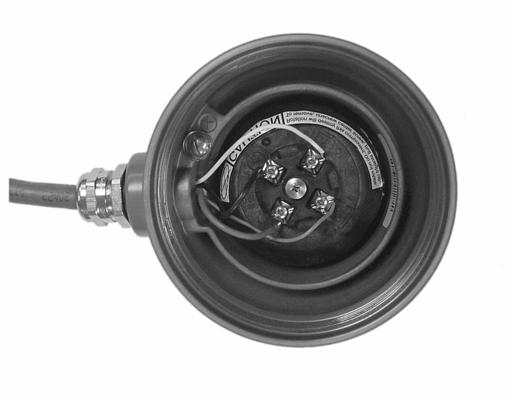
20 9-wire junction box cable wiring STEP 6. Grounding the sensor
21
22
23
24 2003, Micro Motion, Inc. All rights reserved. P/N , Rev. D * * Visit us on the Internet at Micro Motion Inc. USA Worldwide Headquarters 7070 Winchester Circle Boulder, Colorado T (303) (800) F (303) Micro Motion Europe Emerson Process Management Wiltonstraat KW Veenendaal The Netherlands T +31 (0) F +31 (0) Micro Motion United Kingdom Emerson Process Management Limited Horsfield Way Bredbury Industrial Estate Stockport SK6 2SU U.K. T F Micro Motion Asia Emerson Process Management 1 Pandan Crescent Singapore Republic of Singapore T (65) F (65) Micro Motion Japan Emerson Process Management Shinagawa NF Bldg. 5F 1-2-5, Higashi Shinagawa Shinagawa-ku Tokyo Japan T (81) F (81) TM Micro Motion
Micro Motion F-Series Coriolis Flow and Density Sensors. Installation Manual , Rev CC December 2010
 Micro Motion F-Series Coriolis Flow and Density Sensors Installation Manual 20002298, Rev CC December 2010 Safety and approval information This Micro Motion product complies with all applicable European
Installation Manual , Rev DD April Micro Motion ELITE Coriolis Flow and Density Sensors
 Installation Manual 20002158, Rev DD April 2012 Micro Motion ELITE Coriolis Flow and Density Sensors Safety and approval information This Micro Motion product complies with all applicable European directives
Micro Motion F-Series Coriolis Flow and Density Sensors. Installation Manual , Rev CF January 2018
 Micro Motion F-Series Coriolis Flow and Density Sensors Installation Manual 20002298, Rev CF January 2018 Safety and approval information This Micro Motion product complies with all applicable European
Installation Manual , Rev DI March Micro Motion ELITE Coriolis Flow and Density Sensors
 Installation Manual 20002158, Rev DI March 2014 Micro Motion ELITE Coriolis Flow and Density Sensors Safety and approval information This Micro Motion product complies with all applicable European directives
Installation Manual , Rev DH October Micro Motion ELITE Coriolis Flow and Density Sensors
 Installation Manual 20002158, Rev DH October 2013 Micro Motion ELITE Coriolis Flow and Density Sensors Safety and approval information This Micro Motion product complies with all applicable European directives
Installation Manual , Rev CG January Micro Motion F-Series Coriolis Flow and Density Sensors
 20002298, Rev CG January 2019 Micro Motion F-Series Coriolis Flow and Density Sensors Safety and approval information This Micro Motion product complies with all applicable European directives when properly
Installation Manual P/N , Rev. DA June Micro Motion ELITE Coriolis Flow and Density Sensors
 Installation Manual P/N 20002158, Rev. D June 2009 Micro Motion ELITE oriolis Flow and Density Sensors Planning Mounting Wiring Grounding Safety and pproval Information This Micro Motion product complies
Micro Motion ELITE Mass Flow and Density Meters
 Product Data Sheet PS 00374, Rev. A July 2003 Micro Motion ELITE Mass Flow and Density Meters Available with MVD Technology! TM Micro Motion Micro Motion ELITE mass flow and density meters Experience the
Product Data Sheet PS February Model D and DT. Mass Flow and Density Sensors.
 Product Data Sheet PS 00388 February 2002 Model D and DT Mass Flow and Density Sensors www.micromotion.com Model D and DT sensors Micro Motion Model D sensors set the standard for Coriolis flowmeters nearly
Micro Motion T-Series Straight-Tube Mass Flow and Density Meters. Product Data Sheet PS July 2001
 Micro Motion T-Series Straight-Tube Mass Flow and Density Meters Product Data Sheet PS-00371 July 2001 Micro Motion T-Series Straight-Tube Meters Micro Motion is proud to offer you the first single-straight-tube
Coriolis Flowmeter with Model 1700 or Model 2700 Transmitter
 Safety Manual P/N 20004482, Rev. BA April 2011 Coriolis Flowmeter with Model 1700 or Model 2700 Transmitter Safety Manual for SIS 2011 Micro Motion, Inc. All rights reserved. The Emerson logo is a trademark
Installation Manual , Rev DL July Micro Motion ELITE Coriolis Flow and Density Sensors
 Installation Manual 20002158, Rev DL July 2017 Micro Motion ELITE Coriolis Flow and Density Sensors Safety and approval information This Micro Motion product complies with all applicable European directives
Now available with MVD Technology! ELITE Mass Flow and Density Meters
 Product Data Sheet PS-00374 July 2001 Now available with MVD Technology! ELITE Mass Flow and Density Meters Micro Motion ELITE Meters Experience the most accurate Coriolis meters available today. Micro
Micro Motion Model D and DL Coriolis Flow and Density Meters
 Product Data Sheet PS-00388, Rev. F April 2013 Micro Motion Model D and DL Coriolis Flow and Density Meters Micro Motion Model D and DL sensors provide flow and density measurement for liquids, gases,
Micro Motion ELITE Mass Flow and Density Meters
 Product Data Sheet PS 00375 March 2002 Micro Motion ELITE Mass Flow and Density Meters Now available with MVD Technology! www.micromotion.com Micro Motion ELITE Meters Experience the most accurate Coriolis
Technical Data Sheet , Rev HA October Rosemount 8800 Vortex Installation Effects
 Technical Data Sheet 00816-0100-3250, Rev H October 2017 Rosemount 8800 Vortex Installation Effects Contents Contents Chapter 1 Introduction...1 1.1 Temperature effects on K-factor... 1 1.2 Pipe ID effects
Micro Motion Model CNG050 Compressed Natural Gas Flowmeters
 Product Data Sheet PS-00408, Rev. C February 2008 Micro Motion Model CNG050 Compressed Natural Gas Flowmeters Micro Motion Model CNG050 meters are specifically designed for the CNG industry to meet the
Technical Data Sheet PS , Rev C May Micro Motion R-Series Coriolis Flow and Density Meters
 Technical Data Sheet PS-001945, Rev C May 2017 Micro Motion R-Series Coriolis Flow and Density Meters R-Series Coriolis Flow Meters May 2017 Detailed Specifications R-Series accuracy Model Liquid mass
Technical Data Sheet , Rev HB October Rosemount 8800 Vortex Installation Effects
 Technical Data Sheet 00816-0100-3250, Rev HB October 2018 Rosemount 8800 Vortex Installation Effects 2 Technical Data Sheet Contents 00816-0100-3250 October 2018 Contents Chapter 1 Introduction... 5 1.1
Micro Motion Fork Viscosity Meters
 Micro Motion Fork Viscosity Meters Installation Manual MMI-20020994, Rev B July 2015 Direct insertion viscosity meter installation Safety and approval information This Micro Motion product complies with
Micro Motion F-Series Coriolis Flow and Density Meters
 Product Data Sheet PS-00629, Rev. E May 2007 Micro Motion F-Series Coriolis Flow and Density Meters Micro Motion F-Series Coriolis meters offer highly accurate mass flow, volume flow, and density measurement
KNOWLEDGE
 MICRO MOTION WHITE PAPER BY JULIE VALENTINE, MICRO MOTION, INC. Leak Detection and Micro Motion Coriolis Meters KNOWLEDGE WWW.micromotion.com Introduction As pipeline operators try to mitigate the effects
REVOLUTIONIZE YOUR GAS DENSITY AND PURITY MEASUREMENT TECHNOLOGY
 REVOLUTIONIZE YOUR GAS DENSITY AND PURITY MEASUREMENT TECHNOLOGY Micro Motion Gas Density Meter INTRODUCING EMERSON S MICRO MOTION GAS DENSITY METER Our Gas Density Meter (GDM) delivers fast-response online
Micro Motion Fork Density Meters
 Micro Motion Fork Density Meters Installation Manual MMI-20020989, Rev December 2013 Direct insertion density meter installation Safety and approval information This Micro Motion product complies with
Micro Motion F-Series Coriolis Flow and Density Meters
 Product Data Sheet PS-00603, Rev. F December 2007 Micro Motion F-Series Coriolis Flow and Density Meters Micro Motion F-Series Coriolis meters offer highly accurate mass flow, volume flow, and density
Rosemount 485 Annubar Pak-Lok Assembly
 Quick Installation Guide 00825-0300-809, Rev EA Pak-Lok 85 Annubar Rosemount 85 Annubar Pak-Lok Assembly Start Step 1: Location and Orientation Step 2: Drill Holes into Pipe Step 3: Weld Mounting Hardware
Rosemount 485 Annubar Threaded Flo-Tap Assembly
 Quick Installation Guide 00825-0500-809, Rev DB Threaded Flo-Tap 85 Annubar Rosemount 85 Annubar Threaded Flo-Tap Assembly Step 1: Location and Orientation Step 2: Weld Mounting Hardware Step 3: Install
Rosemount 405 Compact Primary Element. Quick Start Guide , Rev HA June 2016
 Rosemount 405 Compact Primary Element 00825-0100-4810, Rev HA NOTICE This guide provides basic guidelines for Rosemount 405. It does not provide instructions for configuration, diagnostics, maintenance,
Micro Motion Model CNG050 Compressed Natural Gas Flowmeters
 Product Data Sheet PS-00408, Rev. D April 2011 Micro Motion Model CNG050 Compressed Natural Gas Flowmeters Micro Motion Model CNG050 meters are specifically designed for the CNG industry to meet the challenges
Rosemount 285 Annubar Pak-Lok Assembly
 Quick Installation Guide 0025-0100-02, Rev AA Pak-Lok 25 Annubar Rosemount 25 Annubar Pak-Lok Assembly Start Step 1: Location and Orientation Step 2: Drill Holes into Pipe Step 3: Weld Mounting Hardware
Rosemount 485 Annubar Flanged Assembly
 Quick Installation Guide 00825-0100-809, Rev DB Flanged 85 Annubar Rosemount 85 Annubar Flanged Assembly Start Step 1: Location and Orientation Step 2: Drill Holes into Pipe Step 3: Assemble and Check
Rosemount 585 Annubar Flanged Flo-Tap Assembly
 Quick Installation Guide 00825-0200-585, Rev AA Flanged Flo-Tap 585 Annubar Rosemount 585 Annubar Flanged Flo-Tap Assembly Start Step 1: Location and Orientation Step 2: Weld Mounting Hardware Step 3:
REVOLUTIONIZE YOUR DENSITY AND CONCENTRATION MEASUREMENT TECHNOLOGY
 REVOLUTIONIZE YOUR DENSITY AND CONCENTRATION MEASUREMENT TECHNOLOGY Micro Motion Fork Density Meter INTRODUCING EMERSON S MICRO MOTION FORK DENSITY METER Our Fork Density Meter (FDM) delivers accurate
Micro Motion ELITE High Capacity Coriolis Flow and Density Meters
 Product Data Sheet PS-001041, Rev. F February 2010 Micro Motion ELITE High Capacity Coriolis Flow and Density Meters Micro Motion ELITE High Capacity Coriolis meters offer unparalleled flow and density
Micro Motion Fork Density Meters
 Installation Manual MMI-20020989, Rev AD March 2017 Micro Motion Fork Density Meters Direct insertion density meter installation Safety and approval information This Micro Motion product complies with
Micro Motion ELITE High Capacity Coriolis Flow and Density Meters
 Product Data Sheet PS-001041, Rev. L April 2013 Micro Motion ELITE High Capacity Coriolis Flow and Density Meters Micro Motion ELITE High Capacity Coriolis meters offer unparalleled flow and density measurement
Micro Motion 7827 Digital Viscosity Meter
 Product Data Sheet PS-001217, Rev. C April 2013 Micro Motion 7827 Digital Viscosity Meter Micro Motion viscosity meters are built to tackle the most demanding process and control applications. Rugged and
Quick Start Guide , Rev FB June Rosemount 485 Annubar Flanged Flo-Tap Assembly
 Quick Start Guide 00825-000-809, Rev FB Rosemount 85 Annubar Flanged Flo-Tap Assembly Quick Start Guide NOTICE This guide provides basic guidelines for Rosemount 85 Annubar. It does not provide instructions
Unarmored Variable Frequency Drive (VFD) Cable Termination Guide
 Cable Termination Guide") Unarmored Variable Frequency Drive (VFD) Cable Termination Guide Be Certain with Belden A Step-by-Step Look at the Connection/Termination of Unarmored VFD Cables Terminating Unarmored Variable Frequency
Unarmored Variable Frequency Drive (VFD) Cable Termination Guide Be Certain with Belden A Step-by-Step Look at the Connection/Termination of Unarmored VFD Cables Terminating Unarmored Variable Frequency
Micro Motion Technical Overview and Specification Summary
 Product Data Sheet PS-00232, Rev. J June 2009 Micro Motion Technical Overview and Specification Summary Emerson s world-leading Micro Motion Coriolis flow and density measurement devices have set the standard
SUBMERSIBLE TRANSDUCER CABLE REPAIR
 SUBMERSIBLE TRANSDUCER CABLE REPAIR One of the most frequent causes of level transducer failure is its cable being cut, which allows moisture to infiltrate the transducer cable jacket. Many of our customers
SATRON VT Pressure Transmitter
 SATRON VT pressure transmitter belongs to the series V-transmitters. SATRON VT is used for 0-1.4 kpa...0-100 MPa ranges. It is a 2-wire transmitter with HART standard communication. In pressure measuring
M-60X. Explosion Proof Flowswitch with In-line Flow. Description. Key Features. Operating Principle. Applications. Custom Version Available
 Explosion Proof Flowswitch with In-line Flow Key Features Well suitable for corrosive and noncorrosive liquids or gases UL recognized for hazardous location ATEX certified for intrinsic safety and encapsulation
EMK-XP ElectroMelt Power Connection and End Seal Kit Installation Instructions
 EMK-XP ElectroMelt Power Connection and End Seal Kit Installation Instructions Description The ElectroMelt EMK-XP Power Connection and End Seal Kit is for use with ElectroMelt EM2-XR and EM3-XR heating
Rosemount 3095FT MultiVariable Flow Data Logger
 Quick Installation Guide Rosemount 3095FT Rosemount 3095FT MultiVariable Flow Data Logger Step 1: Mount the Transmitter Step 2: Consider Housing Rotation Step 3: Set Jumpers and Switches Step 4: Connect
920i Programmable HMI Indicator/Controller Deep Enclosure Installation Instructions PNs 82455, 82456, 82457, 82458, 82459, 82460
 920i Programmable HMI Indicator/Controller Deep Enclosure Installation Instructions PNs 82455, 82456, 82457, 82458, 82459, 82460 This document contains drawings, replacement parts lists, and instructions
Micro Motion Insertion Density and Viscosity Meter Accessories
 Product Data Sheet PS-001057, Rev. F pril 2013 Micro Motion Insertion Density and Viscosity Meter ccessories Micro Motion insertion density and viscosity meters are built to tackle the most demanding process
707Ex. Users Manual. ma Calibrator
 707Ex ma Calibrator Users Manual March 2003 Rev 2 3/03(English) 2003 Fluke Corporation, All rights reserved. Printed in USA All product names are trademarks of their respective companies. Table of Contents
SAFETY INFORMATION & INSTALLATION GUIDE RMX Programmable Power Supplies. About the RMX Safety Information & Installation Guide
 SAFETY INFORMATION & INSTALLATION GUIDE RMX Programmable Power Supplies RMX-4120/4121/4122/4123/4124/4125/4126/4127 About the RMX Safety Information & Installation Guide This guide is intended for users
SITRANS P measuring instruments for pressure
 Overview Application The pressure transmitter is designed for the special requirements of the food, pharmaceutical and biotechnology industries. The use of high-grade materials guarantees compliance with
Installation and Service Instructions for EX Series Explosion-proof Switches
 Installation and Service Instructions for EX Series Explosion-proof Switches ISSUE 4 50009662 WARNING PERSONAL INJURY DO NOT USE these products as safety or emergency stop devices or in any other application
Flow Measurement SITRANS F C
 verview The flow measuring principle is based on the Coriolis Effect. The FCS400 sensor s measuring tubes are energized by an electromechanical driver circuit which oscillates them at their resonance frequency.
M-200X. Explosion Proof Adjustable Flow Switch with Right Angle Flow. Key Features. Description. Operating Principle. Applications
 Explosion Proof Adjustable Flow Switch with Right Angle Flow Key Features Field adjustable Infinite flow range Extremely accurate and sensitive Low pressure drop UL recognized for hazardous location ATEX
Endurance TM Conductivity Sensors
 Endurance TM Conductivity Sensors For additional information, please visit our website at EmersonProcess.com/LiquidAnalysis. Quick Start Guide Part Number: 51A-400/400VP, Rev. S March 2016 Sensor/process
Application Specification Circular Plastic Connector (CPC) Series 45 System 05 AUG 14 Rev D
 Series 45 System 05 AUG 14 Rev D") Application Specification Circular Plastic Connector (CPC) 114-13137 Series 45 System 05 AUG 14 Rev D NOTE i All numerical values are in metric units [with U.S. customary units in brackets]. Dimensions
Application Specification Circular Plastic Connector (CPC) 114-13137 Series 45 System 05 AUG 14 Rev D NOTE i All numerical values are in metric units [with U.S. customary units in brackets]. Dimensions
Quick Start Guide , Rev AB June Rosemount 585 Annubar Flanged Assembly
 Quick Start Guide 00825-0100-585, Rev AB Rosemount 585 Annubar Flanged Assembly Quick Start Guide NOTICE This guide provides basic guidelines for Rosemount 585 Annubar Assembly. It does not provide instructions
C A HEATING CABLE GLAND KIT INSTALLATION INSTRUCTIONS
 C75-100-A HEATING CABLE GLAND KIT INSTALLATION INSTRUCTIONS DESCRIPTION The C75-100-A is a NEMA 4X-rated gland kit used to transition heating cables into a junction box when making connections off of a
Start FINAL. Step 8: Process Leak Protection (Optional) Step 9: Power up the Transmitter. Step 10: Check Process Connections
 Step 9: Power up the Transmitter. Step 10: Check Process Connections") Rosemount Magnetic Flowmeter System (Transmitter and Flowtube) with FOUNDATION fieldbus ProductDiscontinued Start Step 1: Pre-Installation Step 2: Handling Step 3: Mounting Step 4: Installation (Flanged
Rosemount Magnetic Flowmeter System (Transmitter and Flowtube) with FOUNDATION fieldbus ProductDiscontinued Start Step 1: Pre-Installation Step 2: Handling Step 3: Mounting Step 4: Installation (Flanged
Rosemount 8700 Series Magnetic Flowmeter Sensors
 Quick Installation Guide Magnetic Flowmeter Sensors Start Step 1: Pre-Installation Step 2: Handling Step 3: Mounting Step 4: Installation (Flanged Sensors) (Wafer Sensors) (Sanitary Sensors) Step 5: Grounding
SERGE BARIL HA-S HAZARDOUS AREA SEAL KIT
 INSTRUCTIONS DESCRIPTION The HA-S Hazardous Area Seal Kit provides the cable termination and explosion proof seal parts needed to make all in-line electrical splice connections associated with Serge Baril
Model 8800C Vortex Flowmeter
 Vortex Flowmeter Start Step 1: Mount the Flowmeter Step 2: Consider Housing Rotation Step 3: Set the Jumpers Step 4: Connect the Wiring and Power Up Step 5: Review Flowmeter Configuration Product Certifications
Mobrey MSM400 Ultrasonic sludge density measurement system
 Technical specification sheet IP257 October 2008 Mobrey MSM400 Ultrasonic sludge density measurement system Level Features Measuring range up to 50% solids Simple keypad operation HMI menu based programming
MODEL 8682 SUREFLOW ADAPTIVE OFFSET CONTROLLER
 MODEL 8682 SUREFLOW ADAPTIVE OFFSET CONTROLLER INSTALLATION INSTRUCTIONS WARNING: The Model 8682 Adaptive Offset Controller must be wired to 24 VAC only. Wiring the unit to 110 VAC will cause serious unit
C A Heating Cable Gland Kit Installation Instructions
 C75-100-A Heating Cable Gland Kit Installation Instructions Description The C75-100-A is a NEMA 4X-rated gland kit used to transition heating cables into a junction box when making connections off of a
Mobrey MLT100. Displacer Level Transmitter. Product Data Sheet February 2015 IP119, Rev CA. Level, contents or interface measurement transmitter
 Product Data Sheet February 2015 IP119, Rev CA Displacer Level Transmitter Level, contents or interface measurement transmitter Direct or external chamber mounting 4 20 ma HART output ATEX Intrinsically
Automatic Burnout Furnaces 115 to 230-volt Models OPERATOR S MANUAL
 Automatic Burnout Furnaces 115 to 230-volt Models OPERATOR S MANUAL TABLE OF CONTENTS Introduction...3 Warranty...3 On-Line Warranty Registration...3 Safety Instructions........................................................3
Power-Limiting Cables
 Power-Limiting Cables This section provides general design guidelines for power-limiting heat-tracing systems installed on insulated metal pipes. For other applications or design assistance, contact your
Micro Motion 7829 Viscomaster Series Accessories
 Product Data Sheet PS-001222, Rev. C pril 2013 Micro Motion 7829 Viscomaster Series ccessories Micro Motion 7829 Viscomaster viscosity meters are built to tackle the most demanding marine and power applications.
Instruction Sheet. Booster and Wand PRODUCTION AUTOMATION IMPORTANT RECEIVING INSTRUCTIONS CONTENTS
 PRODUCTION AUTOMATION L1840 Rev. O 05/94 IMPORTANT RECEIVING INSTRUCTIONS Instruction Sheet Booster and Wand Visually inspect all components for shipping damage. If any shipping damage is found, notify
Quarter Master Chief Series 92 Actuator
 Quarter Master Chief Series 92 Actuator Installation, Operation and Maintenance Manual File: Series 92 O & M manual Rev. V 4/22/2013 Page 1 of 13 Table of Contents Series 92 Electric Actuator Introduction...
Micro Motion ELITE Coriolis Flow and Density Meters
 Micro Motion ELITE Coriolis Flow and Density Meters Product Data Sheet PS-00374, Rev V April 2013 Ultimate real world performance Unchallengeable ELITE performance on liquid mass flow, volume flow, and
M-100X. Explosion Proof Adjustable Flow Switch with Right Angle Flow. Key Features. Description. Operating Principle. Applications
 Explosion Proof Adjustable Flow Switch with Right Angle Flow Key Features Field adjustable Infinite flow range Extremely accurate and sensitive Low pressure drop UL recognized for hazardous location ATEX
Nuheat WEATHER-READY HEAT TRACE PIPE FREEZE PROTECTION SYSTEM. Self-Regulating Heating Cable Installation Guide. UV Resistant Polyolefin Outer Jacket
 Nuheat WEATHER-READY HEAT TRACE PIPE FREEZE PROTECTION SYSTEM Self-Regulating Heating Cable Installation Guide Tinned Copper Braid UV Resistant Polyolefin Outer Jacket 16 AWG Bus Wire Polyolefin Inner
SATRON VDt Differential Pressure Transmitter
 SATRON VDt differential pressure transmitter belongs to V-transmitter family. The series V transmitters have both analog and smart properties. SATRON VDt is used for -,1kPa...-15 MPa ranges. It is a 2-wire
Rosemount 3095FC MultiVariable Mass Flow Transmitter with MODBUS Protocol
 Quick Installation Guide Rosemount 3095FC Rosemount 3095FC MultiVariable Mass Flow Transmitter with MODBUS Protocol Step 1: Mount the Transmitter Step 2: Connect Wiring Step 3: Set Jumpers and Apply Power
Installation Instructions
 Installation Instructions BW Seals RIS Seal Rubber in shear slurry seal Experience In Motion 1 Equipment Check 1.1 Follow plant safety regulations prior to equipment disassembly: lock out motor and valves.
Micro Motion T-Series Coriolis Flow and Density Meters
 Micro Motion T-Series Coriolis Flow and Density Meters Product Data Sheet PS-00371, Rev K April 2018 Superior flow measurement in a single straight tube flow meter Built-in balance bar provides the best
JBM-100-STB NEMA 4X-rated connection kit Installation Instructions
 JBM-100-STB NEMA 4X-rated connection kit Installation Instructions Power Connection, Powered Splice, Powered Tee, Dual Power Connection, Splice or Tee with Junction Box Approvals Hazardous Locations CLI,
The products you need when you need them.
 The products you need when you need them. TopWorx Express Shipping Program Extensive offering of our most popular proximity sensors and switchboxes. The all-in-one proximity sensor and limit switch. GO
SATRON VVFe Pressure Transmitter
 SATRON VVFe pressure transmitter belongs to Vtransmitter family. SATRON VVFe is used for 0 4 kpa...0500 kpa ranges. It is a 2wire transmitter with HART standard communication. SATRON VVFe pressure transmitter
INLINE Flow sensor for hazardous area II 1 G/D - II 2 D - II 3 GD - I M1
 INLINE Flow sensor for hazardous area II G/D - II D - II GD - I M Type SE0 Ex can be combined with... Flow meter with NAMUR or NPN/PNP output signal Mounting, dismounting of electronics by a Quarter-Turn
Model 3500 Transmitter (9-wire) or Model 3300 Peripheral
 or Model 3300 Peripheral") Quik Referene Guide P/N 3300995, Rev. C April 2003 Model 3500 Trnsmitter (9-wire) or Model 3300 Peripherl Instlltion Instrutions for Rk-Mount For online tehnil support, use the EXPERT 2 system t www.expert2.om.
Quik Referene Guide P/N 3300995, Rev. C April 2003 Model 3500 Trnsmitter (9-wire) or Model 3300 Peripherl Instlltion Instrutions for Rk-Mount For online tehnil support, use the EXPERT 2 system t www.expert2.om.
3M Cold Shrink QT-III Silicone Rubber 3/C Cabinet Mount Termination Kit
 3M Cold Shrink QT-III Silicone Rubber 3/C Cabinet Mount Termination Kit With High-K Stress Relief For 3-Conductor Copper Tape Shield Cables with or without Ground Wires 7600-T-3RJS Series Instructions
VITALink Taped Splice Pigtail Crimp
 A Marmon Wire & Cable Berkshire Hathaway Company VITALink Taped Splice Pigtail Crimp 1 Hour Fire-Rated Splice VITALink MC Cables, UL FHIT 120 Installation Instructions Description The VITALink Taped Splice
JBS-100-STB Single Entry Power Connection with Junction Box Installation Instructions
 JBS-100-STB Single Entry Power Connection with Junction Box Installation Instructions Description The JBS-100-STB is a NEMA 4X rated power connection kit. It is designed for use with Raychem BTV-CR, BTV-CT,
CAUTION The sensor must always be completely filled with process media in order to measure accurately.
 SITRANS F Coriolis Flowmeters Quick Start Before installing, including in hazardous areas, refer to the Operating Instructions on the internet or on the SITRANS F literature CD-ROM. They contain detailed
P. D. Q. Automatic Burnout Furnaces. 115 and 230-volt Models OPERATOR S MANUAL
 P. D. Q. Automatic Burnout Furnaces 115 and 230-volt Models OPERATOR S MANUAL TABLE OF CONTENTS Introduction... 3 Warranty... 3 Safety Instructions........................................................
Remote Sensor Kits. Installation Manual. Document No (Revision C)
") Remote Sensor Kits Installation Manual Document No. 360-0127-01 (Revision C) Sensidyne, LP 1000 112 th Circle N, Suite 100 St. Petersburg, Florida 33716 USA 800-451-9444 +1 727-530-3602 +1 727-539-0550
Remote Sensor Kits Installation Manual Document No. 360-0127-01 (Revision C) Sensidyne, LP 1000 112 th Circle N, Suite 100 St. Petersburg, Florida 33716 USA 800-451-9444 +1 727-530-3602 +1 727-539-0550
MODEL 8635 SUREFLOW ROOM PRESSURE MONITOR
 MODEL 8635 SUREFLOW ROOM PRESSURE MONITOR INSTALLATION INSTRUCTIONS The Model 8635 Room Pressure Monitor must be wired to 24 VAC only. Wiring the unit to 110 VAC will cause serious damage to the unit and
Rosemount Magnetic Flowmeter Systems (Transmitter and Flowtube)
") November 2003 Rosemount 8712D / 8700 Series Rosemount Magnetic Flowmeter Systems (Transmitter and Flowtube) ProductDiscontinued Start Step 1: Pre-Installation Step 2: Wiring Step 3: Basic Configuration
November 2003 Rosemount 8712D / 8700 Series Rosemount Magnetic Flowmeter Systems (Transmitter and Flowtube) ProductDiscontinued Start Step 1: Pre-Installation Step 2: Wiring Step 3: Basic Configuration
1495 Orifice Plate 1496 Flange Union 1497 Meter Section Installation & Operation Manual
 00809-0100-4792 DS-4127 English Rev. AA 1495 Orifice Plate 1496 Flange Union 1497 Meter Section Installation & Operation Manual COMPLETE POINT SOLUTIONS PRINTED Product Manual Model 1495 Orifice Plate
fact sheet Masoneilan * 8007/8008 Series Electro-pneumatic Transducers GE Energy Nozzle Design Reducing Effects of Vibration Overview
 GE Energy Masoneilan * 8007/8008 Series Electro-pneumatic Transducers fact sheet Nozzle Design Reducing Effects of Vibration Overview Model 8007 and 8008 electro-pneumatic transducers convert a low-power
Installation/Start-up Manual CMB_MAN_ABR_CH88 September CH88 In-Situ Combustion O2. Analyzer System
 CH88 In-Situ Combustion O2 Analyzer System Section 1: Section 2: Section 3: Section 4: Section 5: Section 6: Contents General Information Essential Instructions... 2 Symbols used... 3 Overview... 4 System
Installation Instructions (Translation) Marking. Description. Danger, warning and note symbols. Technical data. ANTARES ExtSet.
 Marking. Description. Danger, warning and note symbols. Technical data. ANTARES ExtSet.") Description Marking The ANTARES ExtSet makes it possible to distribute the Remote I/O ANTARES modules of an explosion-protected Remote I/O system ANTARES among a maximum of 4 metal mounting rails. For
Description Marking The ANTARES ExtSet makes it possible to distribute the Remote I/O ANTARES modules of an explosion-protected Remote I/O system ANTARES among a maximum of 4 metal mounting rails. For
Micro Motion R-Series Coriolis Flow and Density Meters
 Micro Motion R-Series Coriolis Flow and Density Meters Product Data Sheet PS-00363, Rev N June 2018 Multi-variable flow and density measurement Basic liquid mass flow, volume flow, and density measurement
1100 Series Piston Type Differential Pressure Gauges
 1100 Series Piston Type Differential Pressure Gauges 1. Safety Before installing, check the Series Number and verify compatibility to the process media and temperature in contact with the wetted parts.
KDM ARMORED FLOW METER & SWITCH
 KDM ARMORED FLOW METER & SWITCH Flow Pressure Level Temperature measurement monitoring control S2 Short Installation Length SS, PTFE or Hastelloy Wetted Parts Analog Output Available 110 F to + 390 F Temperature
Features MICRO-0.25-I MICRO-0.3-I PRODUCTS PANEL
 MICRO-0.25-I MICRO-0.3-I PANEL PRODUCTS General Specifications Outdoor models The new Aurora 250 & 300-watt micro-inverter product offers something new to Power-One customers. The ability to individually
PMKG-J2LP PolyMatrix Powered Splice Kit Installation Instructions
 PMKG-J2LP PolyMatrix Powered Splice Kit Installation Instructions Description The PolyMatrix PMKG-J2LP is a NEMA 4X rated connection kit for use with Raychem BTV-CR, BTV-CT, QTVR-CT, XTV-CT, KTV-CT and
OPTIGAS 4010C Technical Datasheet
 OPTIGAS 4010C Technical Datasheet Sensor for gas dispenser applications Compact design for easy istallation High accuracy with wide measuring range Designed to fit existing dispensers The documentation