Marine Gyro Compasses for Ships' Officers
|
|
|
- Benjamin Wilkinson
- 6 years ago
- Views:
Transcription
1 Marine Gyro Compasses for Ships' Officers BY A. FROST, B.Sc., MASTERMARINER,M.R.I.N. GLASGOW BROWN, SON & FERGUSON LTD. NAUTICALPUBLISHERS 4-10 DARNLEYSTREET
2 Copyright in all countries signatory to the Berne Convention All rights reserved CONTENTS Introduction The International System of U nits. Linear and Angular Motion. xi Chapter I First Edition 1982 ISBN BROWN,SON& FERGUSON, LTD., GLASGOWG41 2SD Printed and Made in Great Britain SECTION1.1 The Free Gyroscope Gyroscopic Inertia The Free Gyro on the Rotating Earth The Daily Motions of Stars Formulae for Drifting and Tilting Directions of Drifting and Tilting Calculations on the Position and the Change of Position of the Spin Axis of a Free Gyro Gyroscopic Precession. The Effect of External Forces on a Free Gyro Rate of Precession Control of the Free Gyro to Produce a North Seeking Instrument To Show that the Control Precession is Proportional to the Tilt The Effect of the Control Precession on the Free Gyroscope The Effect of Latitude on the Controlled Ellipse Control of the Gyro by Liquid Ballistic Factors Influencing the Rate of Precession with a Liquid Ballistic Damping the Controlled Ellipse Damping in Tilt To Show that the Damping Precession is Proportional to the Tilt The Effect of the Damping Precession on the Controlled Ellipse The Settling Position Damping in Azimuth The Damped Spiral for a Gyro Damped in Azimuth The Settling Position Latitude Error Course Latitude and Speed Error Formula for Course Latitude and Speed Error The Change in the Course and Speed Error The Effect of Ship Motions on the Gyro The First Rolling Error The Intercardinal Rolling Error Elimination of The Intercardinal Rolling Error Ballistic Deflection Formula for Ballistic Deflection Eliminating the Effects of Ballistic Deflection Ballistic Deflection in Compasses not Schuler Tuned Ballistic Tilt The Directional Gyro 64 v
3 VI Chapter 2 CONTENTS SECTION2.1 Sperry Gyro Compasses The Sperry Mk Construction of the Mk The Phantom Ring The Outer Member Control of the Mk Damping of the Mk The Follow Up System Action of the Compass when the Vessel Alters Course The Gimbal Support The Compass Card Assembly The Binnacle Correction of Errors Error Correction Signals. The Correction Torque Motor Transmission to Repeaters The S.R. 120 Gyro Compass The Sensitive Element The Phantom Element The Stationary Element The Follow Up System Error Correction Transmission to Repeaters The Mk. 37 Gyro Compass Construction of the Mk Control of the Mk Damping of the Mk The Follow Up System The Electronic Control Unit The Transmission Unit The Speed and Latitude Compensator Unit Correction of Errors Rapid Settling Automatic Levelling The Electrolytic Level 99 Chapter 4 CONTENTS 3.13 The Arma Brown as a Directional Gyro Transmission to Repeaters The Relay Transmitter Synchro Transmission 117 SECTION4.1 The Anschutz Gyro Compasses Construction of the Standard The Twin Rotors Control of the Standard Damping of the Standard The Follow Up System Electrical Supply to the Gyrosphere Error Correction Elimination of Rolling Errors The Standard The Gyrosphere The Outer Sphere The Gimbal Support The Compass Casing The Standard Construction of the Standard Appendix Alternating Currents Electromagnetic Induction Multi Phase Supplies Induction Motors Rotation of a Magnetic Field by Multi Phase Supplies 137 Synchro Transmission and Servo Mechanisms 140 vii Chapter 3 SECTION3.1 The Arma Brown Gyrocompass The Sensitive Element Connection of the Torsion Wires Between Tank and Ball Purpose of the Torsion Wires The Tank and its Supporting Gimbals The Follow Up System Control and Damping The Pendulum Unit The Use of the Pendulum Unit Signal Correction of Errors Correction of Latitude Error Correction of Course Latitude and Speed Error 111
4 PREFACE Modern gyro compasses are reliable, often sealed units which require a minimum of attention from ship's officers, other than the normal starting and stopping routines. These tasks can be carried out without any knowledge of the principles upon which their operation depends. Unnecessary knowledge however is for the inquiring mind. A knowledge of gyro theory is necessary to properly appreciate the capabilities and the limitations of the compass, and the errors to which it is liable. The purpose of this handbook is to provide that knowledge while at the same time providing a text suitable for candidates for Department of Trade Class 1 and Class 3 certificates and for the Department of Trade Electronic Navigation Course. Operating instructions for the compasses described are not included as these are invariably simple and straightforward and are provided by the manufacturers. General theory is described in the first chapter. Subsequent chapters show how this theory is used in the construction of practical gyro compasses in use currently in merchant vessels. The author would like to thank Capt. W. Burger of the University of Wales Institute of Science and Technology, for his help and encouragement after reading the manuscript, and for his suggestions to improve the same.
5 ACKNOWLEDGEMENTS The author acknowledges with thanks the cooperation and help from the following manufacturers of commercial gyro compasses: Sperry Marine Systems, a division of The Sperry Rand Corporation. Anschutz & Co. G.m.b.H. Kiel. S. G. Brown Limited, a Hawker Siddeley Company. Information concerning the Sperry Mk. 20, S.R. 120 and Mk. 37 compasses is published with the kind permission of Sperry Marine Systems. Figures 2.1(a), 2.3 and 2.7(c) and (d) are reproduced from Sperry manuals. Information concerning the Anschutz Standards 4, 6, and 10 is published with the kind permission of Anschutz and Co. Figure 4.1(a) is reproduced from Anschutz manual Information concerning the Arma Brown Compass is published with the kind permission of S. G. Brown Ltd. Figures 3.2(b), 3.3, 3.8, and 3.9 are reproduced from Arma Brown manuals. INTRODUCTION The International System of Units (S.I. Units) All measurements are comparisons with some accepted standard. It is desirable that a common standard is adopted and to this end in 1960 the General Conference of Weights and Measures recommended that an internationally accepted system of units based upon the metric system should be universally adopted. This recommendation has now been widely implemented and the S.I. Units is briefly described here. The International System of Units is based upon the kilogramme, the metre and the second, and there are six fundamental units defined. All other units are derived from, and defined in terms of these fundamental units. The three basic units of mass length and time, which are applicable to the work covered in this book are described. The other three basic units, the units of electrical current, temperature and luminous intensity have no application here and are not described. MASS is an expression of the quantity of matter contained in a body. The unit of mass is the kilogramme (kg) which is arbitrarily defined by the mass of a sample of platinum-iridium alloy preserved at the International Office of Weights and Measures at Sevres in Paris. A convenient sub-unit is the gram me (kg x 10-3). The fundamental unit of LENGTH is the metre, which, although the original intention was that it should be related to the length of a terrestrial meridian, is now arbitrarily defined in terms of the wavelength of a specified radiation of orange-red light from the atom of the gas Krypton-86. The use of physical standards provided by a lwgth of metal rod has ceased to give a definition to the accuracy consistent with modern requirements and measurement techniques. Convenient sub-units are the centimetre (metre x 10-2 ), and the millimetre (metre x 10-3). The fundamental unit of TIME is the second. This was originally defined in terms of the interval between astronomical events, and must necessarily be related to the length of the mean solar day. Observed variations in the length of this period now IPake such a definition inaccurate and the second is now defined in terms of the period of a specified radiation from the Caesium atom, and is measured by atomic clocks which are regulated to the behaviour of the earth in its axial rotation. All units used in the following discussion are derived from and defined in terms of these three basic units. Xl
6
7
8 The moment produced by a couple is measured as the product of one of the forces and the perpendicular distance between their lines of action. When a mass is pivoted about an axis through its centre of mass as in the case of a rotor or wheel, a movement of translation is prevented by the reaction at the pivot and any force acting in the plane of rotation will produce a moment about the pivot which will cause an angular acceleration. The force then produces the same effect as a couple. Torque If a body is being acted upon by two equal and opposing couples in parallel planes, the body is in equilibrium but is under torsion, which is a tendency to twist. The twisting moment is called a torque and is measured by the moment of either of the couples. Torque is often used in a sense synonymous with moment of a couple. The unit of torque is the unit of moment. If a couple is applied to a body which is pivoted and free to rotate such that a moment about the axis of rotation is produced, an angular acceleration will result which is proportional to the moment
9
10 CHAPTER 1 GYROSCOPIC COMPASS THEORY 1.1 Introduction- The Gyroscope A gyroscope consists of a mass in the form of a rotor or wheel which is suspended in such a way that it is free to spin about an axis passing through its centre of mass and perpendicular to the plane of the rotor. This axis is referred to as the spin axis. Ideally the spin axis bearings should be frictionless so that any rotation imparted to the rotor is maintained. If the gyroscope is not constrained in any way so that there are no forces acting upon the rotor so as to alter the direction in which the spin axis points, then the gyro is called a free gyroscope. The best example of a free gyroscope is the earth itself or indeed any astronomical body which is rotating about one of its diameters, as is the earth. Such bodies are freely suspended in space and if we disregard the small gravitational forces arising from the presence of other astronomical bodies, then the spinning earth may be considered to be free from any external forces which act to change the direction in which its spin axis points. The earth therefore exhibits the properties of a free gyroscope, the equatorial mass corresponding to th~ pla~e of the rotor and the earth's axis of rotation constituting the spm axis. In order to construct a free gyroscope on the surface of the earth then the rotor must be supported against the effect of the earth's gravity. The supports must be designed to maintain the freedom of the spin axis of the rotor to take up any direction without constraint. This requires a gimbal mounting which gives the rotor freedom to turn about two axes mutually at right angles and at right angles to the spin axis. It is convenient to adopt the vertical axis, and a horizontal axis mutually at right angles to the spin axis and the vertical axis. The gyro therefore will have freedom to tilt about the horizontal axis and to turn in azimuth about the vertical axis. Friction in the bearings of the gimbal mountings should be negligible to avoid applying torques to the rotor. A free gyro therefore is said to have three degrees offreedom: i. freedom to spin about a spin axis. ii. freedom to turn in azimuth about a vertical axis. iii. freedom to tilt about a horizontal axis. Figure 1.1 shows an arrangement of such a free gyroscope. 1
11
12 4 MARINE GYRO COMPASSES FOR SHIPS' OFFICERS moment of inertia of the cross section of rotor a wili be greater than that of rotor b. Rotor a wili therefore possess greater gyroscopic inertia for any given angular velocity of spin. Angular momentum (H), is given by the product of the angular velocity (w), and the moment of inertia of the cross section about the spin axis (/): H=wI. 1.3 The Free Gyroscope on the Rotating Earth It must be stressed that the orientation of the plane of the rotor is constant with respect to space, and that this direction wili apparently change when considered with respect to the surface of the rotating earth. Any star in the heavens is at such a vast distance from the earth that its motion through space has a negligible effect upon its position with respect to the other stars, and the familiar star consteliation patterns are maintained. A star therefore may be considered as lying in a constant direction in space. It is convenient to consider the spin axis of a free gyro as pointing to a star, imaginary or otherwise, which is referred to as the gyro star. Motions of the spin axis relative to the earth's surface may then be understood by considering the daily motion of the gyro star. This is a subject with which the navigator is familiar. The direction in which the gyro axis points relative to the earth's surface may be expressed by: i. The Tilt: This is the angle of elevation or depression of the spin axis above or below the horizontal. ii. The Azimuth: This is the direction in which the spin axis points relative to the direction of true north. By convention the tilt and the azimuth of that end of the spin axis which is directed towards the north is stated and used in ali discussion of gyro theory. The tilt and the azimuth of the gyro spin axis is equivalent to the altitude and azimuth (bearing) of the gyro star. The movement of the spin axis relative to the earth's surface may be expressed by: i. T~e Tilting: This is the rate of change of the tilt of the spin axis. ii. T~e Dr.ifting: This is the rate of change of the azimuth of the spm axis. The tilting and the drifting of the spin axis are equivalent to the rate of change of altitude and the rate of change of azimuth (bearing) of the gyro star. GYROSCOPIC COMPASS THEORY Daily Motion of the Stars Here it may be advantageous to consider the apparent motions of th~ sta~s, resulting from the daily rotation of the earth about its own spm axis. The earth rotates about an axis through its poles once in 23h 56m 4 09s of solar time. This period is calied a sidereal day and may be subdivided into 24 sidereal hours. In the foliowing discussion any reference to time wili assume sidereal time, and as the sidereal day may be taken to be the interval required for a 360 rotation of the earth, the rate of rotation may be expressed as 15 per hour, or as 15 minutes of arc per minute of time, whichever is convenient. The west to east rotation of the earth is apparent to an observer on the earth's surface as an east to west rotation of the celestial concave about an axis which is coincident with the earth's axis. It is convenient therefore to consider the earth as stationary and the celestial sphere to rotate in the opposite direction. As the axis of rotation of the heavens defines the celestial poles, ali points on the sphere wili appear to describe circular paths around the poles, which wili be the only points on the sphere which do not appear to move relative to the earth's surface. The complete circle described by the star in the sidereal day wili sometimes lie completely above the observer's horizon and sometimes wililie partialiy below the horizon. Whether the star sets or not will depend upon which is greater, the observer's latitude or the stars angular distance from the pole. Consider an observer situated at one of the earth's poles, say the north pole. The north celestial pole will lie at the observer's zenith, the point in the sky directly above him. The rotation of the stars about the pole will also be therefore about the zenith. AlI stars will describe a circle paraliel to the horizon, maintaining a constant altitude. (This altitude wili be equal to the stars declination.) There will be no rising or setting phenomena. These conditions are illustrated in figure 1.3. The spin axis of a free gyro at the pole will maintain a constant tilt while drifting westwards around the horizon at a rate equal to the earth's rotation, that is 15 per hour. A gyro set with its spin axis directed towards the zenith, that is with a tilt of 90 is pointing at the celestial pole. It would therefore continue to point in the same direction as the pole marks a constant direction in space which has no apparent motion relative to the earth's surface. Consider now an observer at the equator. His zenith will lie on the equinoctial or celestial equator and the north celestial pole must lie on the horizon bearing north. This is iilustrated in figure 1.4. As the axis of rotation now lies in the plane of the observer's horizon, the rotation must carryall celestial bodies above and below the horizon for equal periods of time. Furthermore all circles of declination cut the horizon in a right angle, so that any body wili, at
13 the moment of rising be moving perpendicularly to the horizon. It will then spend 12 hours above the horizon before setting at which time it will again be moving perpendicularly to the horizon. The point at which a star crosses the horizon is determined by the star's declination. A star with declination zero, that is a star which lies on the celestial equator, will rise bearing due east, will pass through the zenith, and will set bearing due west. The rate of change of altitude will be equal to the rate of the earth's rotation, 15 per hour. Consider the motion of the spin axis of the free gyro at the equator, assuming that it is set initially pointing due east and horizontal. It is pointing at the gyro star of zero declination which is rising. The spin axis will tilt upwards at the rate of 15 per hour (i.e. tilting = 15 per hour), but the drifting is zero. The azimuth will remain 090 until the spin axis is directed towards the zenith. Thereafter the azimuth will be 270 with the tilting -15 per hour, the axis again becoming horizontal as the gyro sets bearing due west. A star situated at the celestial pole would have no motion relative to the earth's surface. A gyro spin axis which is set pointing north and horizontal would therefore remain so. Drifting and tilting would be zero. A star with a declination other than zero or 90 would cross the horizon perpendicularly with an amplitude equal to the declination. The star would rise to a maximum altitude equal to its polar distance as it crosses the meridian. The azimuth will change during its passage across the sky but at the moment of rising or setting the rate of change of azimuth would be zero. A gyro spin axis which is set horizontal therefore will have zero drifting irrespective of its azimuth. In general drifting may be taken as zero at the equator as long as the tilt is small. As a gyro compass never attains a large tilt this assumption is a reasonable approximation. The rate of tilting will vary as the sine of the azimuth. Consider now an observer in an intermediate northerly latitude. The zenith will lie between the celestial pole and the celestial equator. Figure 1.5illustrates an observer in latitude 40 0 N. The plane of the celestial equator is inclined to the observer's vertical by 40 and will therefore cut the horizon at an angle of 500.
14 In figure 1.5 three circles of declination are shown. Star X 1 has declination same name as the latitude and less than the latitude. At rising (at Xl) the azimuth will be increasing and will continue to do so until the star crosses the meridian at Xl' south of the observer's zenith. Star X 2 has declination greater than the latitude and will cross the meridian to the north of the zenith, at X 2 Star X 3 is circumpolar, that is it does not set below the horizon to an observer in this latitude. A gyro spin axis will, if its projection onto the celestial sphere is considered, trace out such circular paths around the pole. The radius of the circle traced out will depend upon where the spin axis is initially pointing. If the axis is set horizontal and directed towards X 1 to the east of the meridian, then it will trace out the circular path associated with the star X l' If the spin axis is set pointing north and tilted upwards to point towards X 3 then the circle traced out will be that associated with the circumpolar star X 3' It is sometimes convenient to show these circular paths as seen by an observer facing the northern horizon. Figure 1.6 shows the northern horizon and the meridian passing through its northern point. The pole is seen above the horizon bearing north with an altitude equal to the observer's latitude. The circular paths referred to in figure 1.5 are shown and labelled accordingly. Note that the stars will be seen to move anticlockwise rising to the east of the pole and setting when to the west of the pole. 1.5 Formulae for Drifting and Tilting From the discussion of the apparent daily motions of stars in section 1.4 we may deduce simple formulae for the Drifting and the Tilting of a free gyro. Drifting (Dg) We have seen that the drifting of a free gyro spin axis is equal to the rate of the earth's rotation for a free gyro placed at either of the
15 10 MARINE GYRO COMPASSES FOR SHIPS' OFFICERS earth's poles. The earth's rotation to the east will cause the spin axis to appear to drift to the west at a rate of 15 per hour. This is the maximum rate. At the equator a free gyro with its spin axis horizontal will be tilting upwards perpendicularly to the horizon, and the drifting at this time will therefore be zero irrespective of the azimuth. Thus for a gyro whose spin axis has a negligible tilt the drifting is zero at the equator. Hence we may deduce: Drifting = 15' sine latitude per minute oftime. (Although this is true only for a negligible tilt, the formula is adequate for gyro work as a gyro compass operates with its spin axis substantially horizontal.) Tilting (Tg) It was seen that at the poles the tilting of the spin axis was zero. At the equator a maximum tilting of 15 per hour was experienced if the spin axis was directed due east/west. This rate was shown to be dependent on the azimuth. If the spin axis is aligned with the meridian the rate of tilting is zero. It may be deduced therefore that the rate of tilting varies as the cosine of the latitude and the sine of the azimuth. Hence: Tilting = 15' cos latitude sin azimuth per minute of time.! 'The foregoing does not constitute strict mathematical proof of the formulae but the discussion may help the student to remember or to think out the formulae for himself. 1.6 Direction of Drifting and Tilting It is most important that the student is able to determine the direction of the drifting and the tilting, from any given initial azimuth and tilt. This may be determined by considering figure 1.7 which shows the circular path traced out by a star during a sidereal day, around the north celestial pole, as seen by an observer facing the northern horizon. The plane of the page is representing the curved surface of the celestial sphere, and the north celestial pole has an altitude above the horizon equal to the observer's latitude. The star will circle the pole in the direction shown, that is increasing its altitude when it is to the east of the meridian, crossing the meridian above the pole, and decreasing its altitude when to the west of the meridian. This is the path traced out by the projection of the north end of the spin axis of a free gyro which is initially set pointing in the direction X. From the figure we may deduce that, when the north end of the axis is directed to the east of the meridian, that end will be
16 12 MARINE GYRO COMPASSES FOR SHIPS' OFFICERS A gyro compass operates with a zero or a very small tilt. As the altitude of the celestial pole is equal to the observer's latitude, in north latitude the gyro compass spin axis will operate always with the north end directed below the north pole. The drifting will therefore always be eastwards or positive. In south latitude the north pole will be below the northern horizon and the spin axis will be directed above the pole. The drifting will therefore be westwards. We may say therefore that for a gyro compass in north latitude the drifting is eastwards or positive, and in south latitude the drifting is westwards or negative. 1.7 Calculations on the Position and the Rate of Change of Position of the Spin Axis of a Free Gyro The formulae derived for drifting and tilting give values which are valid only for an instant in time. The value given for tilting depends upon the value used in the formula for the azimuth and this will be constantly changing. The formula for drifting is valid only for a zero tilt. The use of these formulae is therefore limited and they are not suitable for use in problems covering a long interval of time. These problems are best tackled using the trigonometrical solution of the PZX triangle for the gyro star, which problems are familiar to the navigator who has studied the principles of navigation or nautical astronomy. To illustrate these problems it is usual to draw an approximate projection of the celestial sphere onto the rational horizon based upon the equidistant projection. Accurate scale drawing of such figures is not necessary but the general procedure for figure drawing is given here. Procedure is referred to figure Describe a circle to represent the rational horizon. The view of the celestial sphere is from above the observer's zenith so that the centre of the circle will always represent the zenith. This is labelled Z. The north point of the horizon is marked by N and the south point by S. 2. Draw in the line NZS to represent the observer's meridian. This divides the sphere into two halves, east of the meridian in which all bodies rise, and west of the meridian in which all bodies set. Draw in WZE to represent the observer's prime vertical. 3. Mark an approximate scale of degrees along NZS in say 10 intervals. This scale may be used as a scale of latitude, declination or altitude. 4. Mark in the point Q where the celestial equator cuts the meridian. The distance ZQ will be equal to the observer's latitude. Q will be to the south of Z if the latitude is north, and Q will be to the north of Z if the latitude is south. Draw an arc through W, Q and E to represent the celestial equator. 5. Now locate some point which is occupied by the gyro star at some instant, from information given in the question. For example it may be given that initially the gyro axis is horizontal and pointing in a direction 045. This would locate the gyro star on the horizon at X in figure 9.8. The examples worked in the following section will illustrate this further. 6. For the present purpose it is now sufficiently accurate to draw a circle centred upon P through the gyro star so located. This circle represents the path followed by the gyro star during the daily rotation of the earth. The following examples worked with notes will now show how such a figure may be used to solve this type of problem. Example 1 A free gyro in latitude 40 0 N is initially set pointing north with its spin axis horizontal. Find the position of the north end of the spin axis 12 hours later. Notes A diagram may first be drawn for 40 north latitude. The gyro star is then initially positioned on the horizon (gyro axis horizontal), and bearing north. The gyro star is therefore initially at N in figure 1.9. The circle drawn about P passing through N then represents the path traced out by spin axis during one rotation of the earth. In 12 sidereal hours the spin axis will have traced out 180 of this B
17
18
19
20
21
22
23
24
25 30 MARINE GYRO COMPASSES FOR SHIPS' OFFICERS The control weight has no effect,but due to the rotation of the earth, the north end of the spin axis will immediately tilt upwards, as it is directed to the east of the meridian. It will also drift to the east as it is directed below the celestial pole. This far the gyro behaves as a free gyro, but as soon as the axis leaves the horizontal the control weight causes a precession north end westwards. It has been shown that the control precession is proportional to the tilt so that with a small tilt the control precession will be less than the drifting. The north end therefore drifts to the east but at a reduced rate. As the tilt increases then so does the control precession. There will be a value of tilt when the control precession is equal to the drifting. At this point the north end of the spin axis will cease to go to the east and will move vertically upwards under the influence of the tilting. This has occurred at point B in figure As the tilt increases further then so doe's the control precession, which will now be greater than the drifting and the north end will move to the westwards towards the meridian. This westerly motion will increase as the tilt and therefore the control precession increases. The tilting however varies as the sine of the azimuth so that as the axis approaches the meridian the tilting will decrease from a maximum at B to zero when the axis aligns with the meridian. The increase in control precession and the decrease in the tilting are evident in the length of the vectors at positions C and D in figure The axis moves more and more rapidly towards the meridian tracing out an elliptical path. At E the axis is aligned with the meridian, the azimuth is zero, and the tilting is therefore zero. (The rate of change of altitude of a star is zero when it crosses the meridian.) The tilt is maximum at this point so that the control precession is also a maximum and the north end of the spin axis is moving rapidly to the west. As it passes to the west of the meridian the tilting becomes negative or north end downwards and the axis begins to move towards the horizontal. As the tilt decreases then so does the control precession. The negative tilting increases as the aximuth increases. This is evident in the length of the vectors which represent the tilting and the precession at points F and G. At point H the tilt has decreased to a value which makes the control precession equal to the drifting. The westwards movement of the north end therefore ceases and thereafter it moves to the east. The azimuth is maximum at point H so that the tilting will be maximum negative. At point I the axis is again in the horizontal and the control precession has gone to zero. As the north end of the spin axis tilts below the horizontal the control precession becomes north end eastwards and is then aiding the drifting and the axis moves rapidly towards the meridian. It is in the meridian at J and the tilting is zero. It will then become positive or north end upwards and the axis will return to the initial position with the north end directed towards the point A to complete the ellipse. The GYROSCOPIC COMPASS THEORY 31 controlled gyro will oscillate in this way with the spin axis always seeking the meridian but never settling in the meridian. The ellipse traced out will be of the same dimension on each oscillation The Effect of Latitude on the Controlled Ellipse A controlled gyro at the equator set initially horizontal and pointing to the east of the meridian will be subject only to tilting. The value of the rate of drifting at the equator is zero when the tilt is negligible. That end of the spin axis will therefore tilt upwards moving perpendicularly to the horizon. Immediately the axis moves out of the horizontal the control precession will carry the north end westwards towards the meridian. The maximum azimuth occurs therefore with the spin axis in the horizontal. In the absence of any drifting the spin axis must move westwards when the north end is tilted upwards and eastwards when it is tilted down. The controlled ellipse traced out will therefore be symmetrical about the horizon as well as about the meridian. Such an ellipse is shown in figure In general the greater the latitude then the greater the drifting, and the greater must be the tilt to give a control precession to equal the drifting. The controlled ellipse is therefore lifted relative to the horizon by an increase of northerly latitude.
26 GYROSCOPIC COMPASS THEORY 33 find its own horizontal and will be evenly distributed about the eastwest horizontal axis. It will therefore have no effect on the gyro. That is its weight is acting vertically down through the centre of the rotor and no torque is exerted about any of the gyro axes. In figure 1.26(b) the north end of the rotor spin axis has tilted An increase of southerly latitude will depress the controlled ellipse traced out by the north end of the spin axis, below the horizon as in south latitude the drifting of the north end will be to the west. Such an ellipse is shown in figure Control ofthe Gyro by Liquid Ballistic The control of a gyro by solid control weight is not used in practical compasses as its use presents problems when the compass is subjected to the accelerations associated with the movement of a ship in a seaway (see Rolling Errors). Commonly used is a gravity control by a liquid ballistic, which flows between the north and south sides of the rotor under the influence of gravity when the gyro axis tilts out of the horizontal. Consider figure 1.26(a). This shows a rotor and rotor casing. Attached to the rotor casing by a connection at the bottom of the casing is a pair of bottles or pots, one to the north and the other to the south of the east-west horizontal axis. The pipes are connected at their bases by an unrestricted pipe which allows free flow between the two pots. The pots contain a quantity of liquid; commonly used is mercury because of its high density. The pots are also connected by a pipe between their upper ends to allow equalisation of air pressure, ensuring that flow is not restricted by a build up of pressure in the top of the pots. The whole is symmetrical about the east -west axis and the centre of mass of the ballistic system must coincide with that of the rotor when the rotor axis is horizontal and the liquid is equally distributed between the pots. In figure 1.26(a) the rotor axis is shown horizontal. The liquid will
27 34 MARINE GYRO COMPASSES FOR SHIPS' OFFICERS upwards, and there has been a flow of liquid to the south control pot. The imbalance now causes a torque about the horizontal east-west axis which is transmitted to the rotor via the link to the rotor casing and via the spin axis bearings. The effect is as if a force were exerted on the rotor at the bottom on the south side (at F). Note that this is identical to the action of the top mounted control weight. This arrangement therefore constitutes a top heavy gyro. The spin must be anticlockwise viewed from the south in order to create the required westerly precession when the north end tilts up. This method is used in a wide range of compasses manufactured by the Sperry Gyroscope Company Ltd. Note A liquid ballistic has been used in a bottom heavy configuration by S. G. Brown Ltd. in compasses which are now obsolete. To achieve bottom heaviness the liquid must be raised to the high side when the gyro axis tilts. (The Brown Type A and B compasses, which employed this method have now been superseded by the Arma Brown compass and no more will be said about this method.) 1.15 Factors Influencing the Rate of Precession with a Liquid Ballistic As with the solid control weight we can show that the rate of precession will be proportional to the tilt, for small angles of tilt. The rate of precession is given by:
28 1.16 Damping the Controlled Ellipse The controlled or north seeking gyro will never settle in the meridian. It will only oscillate about the meridian. There will in fact be one position in which the controlled gyro will remain pointing in a constant direction, if initially set there, that is pointing north with a tilt such that the control precession is equal to the drifting. Precession thus cancels the drifting and there is no tilting in the meridian. This will require a tilt of the north end upwards in north latitude and downwards in south latitude. The tilt necessary will increase with increasing latitude. This position however is an unstable position and any slight deviation from it will result in the axis commencing an elliptical oscillation. It will not return to the equilibrium position. The requirement for a gyro compass is that it will initially seek and attain the meridian, and settle in an equilibrium position pointing north, and if disturbed from this position will return to it. That is the equilibrium position must be stable. The term 'damping' means the provision of a precession which will cause successive oscillations of the controlled ellipse from side to side of the meridian, to reduce in amplitude until they are infinitely small, and an equilibrium position is reached. The controlled ellipse becomes in fact a spiral inwards towards this equilibrium position, as shown in figure Damping may be achieved by the provision of a precession in tilt (towards the horizon), or a precession in azimuth (towards the meridian ) Damping in Tilt To create a precession in tilt, that is about the horizontal east-west axis, a torque about the vertical axis is required (section 1.8). A number of different methods of achieving this have been, and are in use. Perhaps the method best suited to explanation of basic principles is that used in the Sperry Mark 20 gyro compass. FIG The damping weight on top of the rotor case offset to the west of the vertical axis. A tilt of the 'vertical' axis out of the true vertical will produce a torque about the vertical axis equal to Wx sine tilt. In figure 1.28 a rotor and rotor case is shown. The rotor case carries a small weight on top and in the plane of the rotor, but offset slightly from the vertical axis. The rotor casing is supported inside a vertical ring, which surrounds the rotor casing in the east-west plane. This vertical ring itself tilts about horizontal east-west bearings, when the rotor tilts, because the rotor i!isupported within the vertical ring by bearings in the vertical axis. When the rotor tilts the vertical axis must therefore tilt also. This method of damping requires this 'nominal' vertical axis to tilt out of the vertical. With the spin axis horizontal the damping weight has no effect, but when the spin axis tilts out of the horizontal, the damping weight will exert a torque about the vertical axis which has tilted out of the
29
30 40 MARINE GYRO COMPASSES FOR SHIPS' OFFICERS north end of the spin axis of a controlled and damped gyro in north latitude. The spin axis is initially set with one end pointing at the point A, that is horizontal and directed to the east of the meridian. The following account describes how the drifting, the tilting, the control precession and the damping precession interact to produce this spiral towards the settling position. At position A when the axis is horizontal there is neither control nor damping precessions. This end will immediately acquire a positive tilt due to the earth's rotation. It will also drift to the east. As the axis goes out of the horizontal a westerly control precession and a smaller damping precession towards the horizon are introduced. The westerly control precession reduces the easterly drifting and the downwards damping precession reduces the upwards tilting. At position B the tilt has increased to the value which gives a control precession equal to the drifting. The easterly drifting of the north end of the spin axis will therefore cease at this point. The movement will be vertically upwards under the influence of the tilting, which is maximum at this point. The rate of tilting will however be reduced by the damping precession. As the tilt increases so does the control precession and the damping precession. The control precession is now greater than the drifting and the north end of the spin axis moves westwards towards the meridian. This means that the rate of tilting will be reducing while the damping precession is increasing. There will come a point before the spin axis reaches the meridian, when the tilting is equal to the damping precession. The tilt will therefore be a maximum at this point, which is point C in figure 1.29, and will be reducing when the spin axis aligns with the meridian, when the tilting goes to zero. As the north end of the spin axis moves to the west of the meridian the tilting of that end becomes downwards, and is now acting with the damping precession. The axis moves rapidly towards the horizontal. The amplitude of the swing in azimuth will be reduced compared with that of the controlled gyro, by the action of the damping precession towards the horizon. The maximum azimuth is reached at point D where the control precession is again equal to the drifting and therefore the north end of the spin axis ceases to move westwards and thereafter will move back to the east, towards the meridian. The control precession and the damping pre~ession reduce to zero as the axis approaches the horizontal agam. It will be noted that the damping precession is acting against the tilting when the latter is directed away from the horizon and is acting with the tilting when it is directed towards the horizon. Consequently each time the spin axis comes back to the level of the settling position, that is the level at which the control precession is equal to the drifting, the azimuth must reduce. After a number of oscillations it will therefore reduce to zero. As the north end of the spin axis tilts below the horizontal, the GYROSCOPIC COMPASS THEORY 41 control precession becomes eastwards, that is in the same direction as the drifting. The damping precession becomes upwards. Maximum downwards tilt of the north end will occur before the axis comes into line with the meridian, where the damping precession is equal and opposite to the tilting. As it crosses the meridian the spin axis is already moving towards the horizontal. One complete oscillation about the meridian is completed when the axis arrives at position E. The degree of damping is expressed by the 'damping factor'. This is defined as the ratio ofthe total swing in azimuth on two successive half cycles. In figure 1.29 the damping factor will be given by the ratio a : b The Settling Position The spin axis will reach an equilibrium position at which the drifting is equalled and opposed by the control precession and the tilting is equalled and opposed by the damping precession. For a gyro in any latitude other than the equator there will always be some amount of drifting given by 15' sine latitude per minute of time. In north latitude the drifting will be north end to the east. There must be therefore a control precession north end to the west to oppose and counteract this. This requires an upwards tilt of the north end of the spin axis. However this tilt will also produce some amount of damping precession in a sense north end of the spin axis downwards, and this must be counteracted by an upwards tilting which is only obtained by the north end being off the meridian to the east. Thus in north latitude the compass will settle with the north end of the spin axis tilted above the horizontal and displaced to the east of the meridian. The tilt will be small and of little consequence in the operation of the compass. The displacement from the meridian
31 42 MARINE GYRO COMPASSES FOR SHIPS' OFFICERS constitutes an error of the compass. This error is called the latitude error. (It is also referred to as the damping error or the settling error.) The equilibrium between drifting and control precession and the tilting and the damping precession is illustrated in figure At the equator the drifting is zero when the spin axis is horizontal, and no compensating control precession is required. This means that the spin axis will settle in the horizontal and the damping precession will also be zero. The axis must therefore settle in the meridian where the value of the tilting is zero. In south latitude the drifting of the north end of the spin axis is to the west, requiring an easterly control precession to compensate. Consequently the north end must settle with a downwards tilt and to the west of the meridian so that the downwards tilting opposes the upwards damping precession. The sign of the latitude error therefore depends on the sign of the latitude, an easterly error being produced in north latitude and a westerly error in south latitude. A numerical analysis of the error is given in section GYROSCOPIC COMPASS THEORY 43 increased and its motion away will be decreased. A damping precession in azimuth must be created in a similar way to the control precession, that is by a torque about the horizontal east-west axis. A precession merely created by the effect of gravity when the spin axis tilts however will not be suitable as its direction would only depend on whether the north end of the spin axis was tilted up or down, and could be directed towards or away from the meridian. Such a precession would only modify the rate of the control precession and would not achieve damping. It should be evident that the damping precession must always be directed towards the meridian. This may be achieved by creating the precession in azimuth by a torque about the horizontal axis by a flow of liquid under the influence of gravity when the axis tilts, but causing a lag between cause and effect by introducing a restriction to the flow. The action of the ballistic will then be out of phase with the tilt which caused the flow. Figure 1.32(a) shows the direction of the precession in azimuth FIG The settling position for a compass damped in tilt. South Latitude Damping in Azimuth (Damping towards the Meridian) The amplitude of successive oscillations may be reduced by a precession in azimuth, that is a precession towards the meridian. Such a precession is therefore similar to the control precession, but in order to damp the controlled ellipse it must act with the control precession, when the latter is directed towards the meridian, and must oppose the control precession when it is acting away from the meridian. Thus the motion of the axis towards the meridian will be without any restnction causing delayed action. The direction of rotation of the rotor is clockwise viewed from the south, i.e. that direction appropriate to a bottom heavy compass. The control precession is produced by a bottom heavy effect while the damping precession is produced by a top heavy effect.the resulting precessions will therefore be of opposite direction. Figure 1.32(b) now shows the effect of introducing a lag in the action of the damping precession equal to one quarter of the period of oscillation. It will be noted now that the direction of the precession is now always towards the meridian. What has occurred is that the precession which originally was caused when the axis was in the north end up and to the east quadrant, now does not occur until the north end is up and to the west. The direction which originally
32 GYROSCOPIC COMPASS THEORY 45 It is important to realise that the damping precession produced by this method can only be produced when there is a change of tilt of the spin axis. No damping precession can be caused when the spin axis has a constant tilt. This is because the delaying action of the restriction to the flow of the liquid, can only be effective when there is, in fact, a flow. A constant tilt of the axis will not cause any transfer of liquid so that the delaying action is ineffective. Under these circumstances the damping torque will always act in the opposite direction to the control torque thus merely reducing its effect. The importance of this is that when the axis has settled it will have a constant tilt, and therefore in the settling position there will be no damping precession. The significance of this may now be evident to the student. It will however be discussed further when the settling position is discussed in section Path Traced Out by the Spin Axis of the Gyro Damped in Azimuth Figure 1.33 shows a damped spiral traced out by the north end of the spin axis of a gyrocompass damped in azimuth. The direction of the vectors representing the damping precession assume that the delay in the action of the damping torque is exactly a quarter of the cycle. This is not necessarily so and the exact shape of the trace may vary. It is important to note however that the axis will cross the meridian moving horizontally, because at the moment of being in the meridian the tilting is zero, and there is no precession in tilt. On the other hand the axis will reach maximum azimuth and commence moving back towards the meridian before it reaches the settling level, and under the action of the damping precession towards the meridian will move in azimuth more rapidly when moving towards the
33
34
35 It should be clear from this formula that the magnitude of the steaming error does not depend in any way upon the compass itself, its design or characteristics. The error is the same for all compasses, being determined by the course, speed and latitude of the vessel. This is an approximate formula which is adequate for all practical purposes at sea in normal navigable latitudes. The error varies as the secant of the latitude so that as the latitude approaches 90 the error approaches infinity. Large errors will be obtained in high latitudes. A speed of 20 knots on a northerly course in latitude 60 gives an error of 2!0. The same conditions in latitude 75 give an error of 5. The approximations inherent in this formula are valid only if the speed of the vessel is small compared with the linear speed of the earth's rotation. This will always be the case in a marine craft in normal navigable latitudes. At high speed such as that encountered in aircraft and in any craft in very high latitudes a more accurate formula must be used. The large errors due to the high speeds and the effect ofthe considerable accelerations imposed upon the compass by aircraft manoeuvres, preclude the use ofthe marine gyro compass in aircraft Accurate Formula for Course Latitude and Speed Error If the velocity ofthe vessel across the earth's surface is considerable compared with the earth's rotation then the error becomes large. It can no longer be assumed that the sine or tangent of the error is equal to the error in radians. Furthermore the east-west component of the vessel's velocity will increase or decrease the effective velocity of the earth's east-west rotation. If the vessel is steaming to the west then effectively the earth's rotation is reduced. It then becomes 900' cos lat. - v sin course. If the vessel is steaming eastwards then effectively the earth's rotation is increased. It then becomes 900' cos lat. + v sin course per hour. Also the motion of the vessel northwards along the false meridian will be (v cos course) cos error. Thus the condition when the tilting due to the earth's rotation is equal and opposite to the tilting due to the vessel's speed will be:
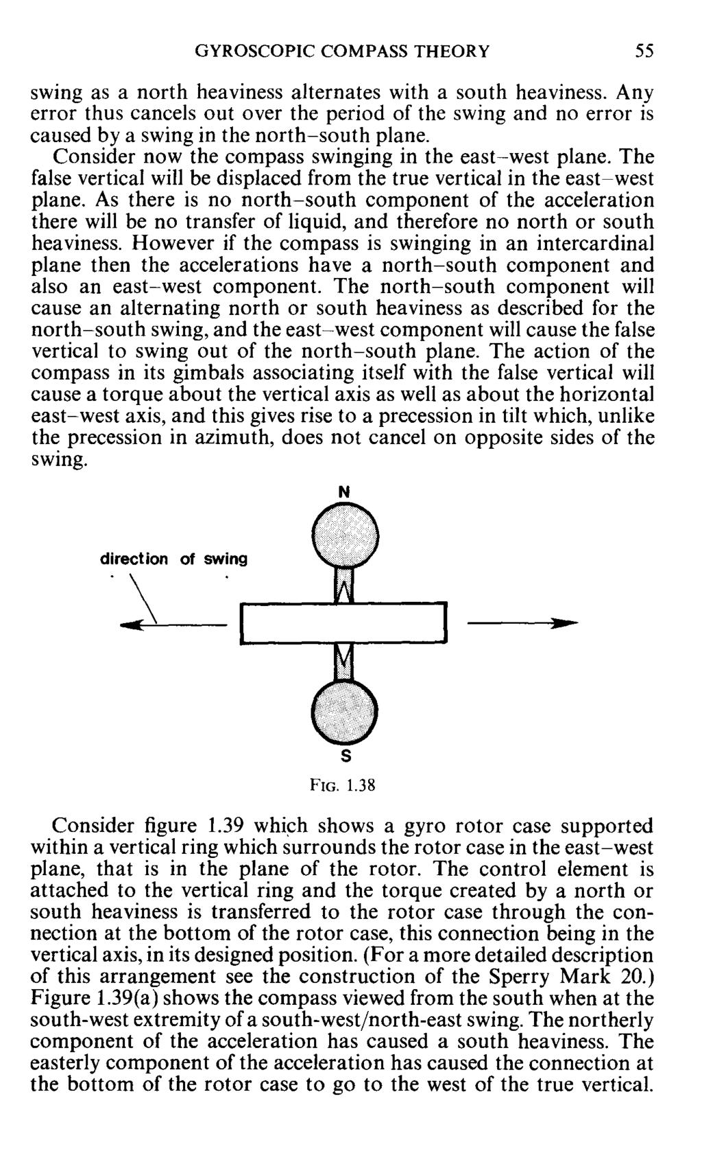
36 GYROSCOPIC COMPASS THEORY The Change in the Course and Speed Error The approximate formula for the course and speed error gives, for a vessel steaming north at 20 knots in latitude 60, an error of 2! W. If that vessel now alters course by 180 and steams south the error wil1 become 2! E. The compass wil1 resettle in a position 5 to the east of the original settling position. In order to resettle the axis will execute a damped spiral and will therefore for a period following the alteration be unsteady. A series of manoeuvres in rapid succession could produce serious errors in the compass. There are two ways in which this problem may be tackled. The course latitude and speed error may be eliminated entirely by creating a precession of the spin axis which is equal and opposite to the false tilting of the axis caused by the north-south component of the vessel's speed. The tilting occurs at the rate of this component, (v 'coscourse) (section 1.25). The precession to compensate for the false tilting must therefore be equal to v cos course. The compass will then settle in the true meridian, (damping error corrected), and will therefore not require to resettle after an alteration. This method is employed in the Arma Brown Compass and the Sperry Mark 20, these compasses being discussed in more detail in the chapters devoted to them. The course latitude and speed error is, in some compasses, allowed to occur and is then apparently corrected by shifting the lubber line by an amount equal to the error. In other compasses the error must be allowed for by the navigator, who extracts the error from tables supplied. In each case the compass wil1 require to resettle after each alteration of course or speed, and the unsteadiness associated with the damped spiral must be avoided. This is done by causing the compass to precess directly to the new settling position by making use of another, otherwise unwanted, effect of the alteration of course or speed. This is the Ballistic Deflection which is described in section This section fully explains how the ballistic deflection is used to solve the problem of the change in the course and speed error The Effect of Ship Motions on the Gyroscope The correct and accurate operation of the gyro compass depends upon the effect of gravity on the control and damping element of the compass. The acceleration due to the earth's gravity acts vertically downwards and defines the horizontal for the compass. If the compass is subjected to other accelerations such as those associated with the motion of a ship in a seaway, the compass will react to these accelerations as they will be indistinguishable from that of the earth's gravity. The compass will sense the resultant of all the accelerations to which it is subjected, and this resultant will define a 'false' vertical and thus a false horizontal. The effect of ship motions are called Rolling Errors but they are not errors in the sense that they can be assessed and allowed for, but their effect is to produce spurious wandering of the compass. They must therefore be eliminated as far as possible in the design of the compass so that the navigator has no part to play in their compensation The First Rolling Error A body which is set swinging pendulously, and whose mass is distributed preferentially in one vertical plane, is subject to dynamic forces which turn the plane in which the mass lies, into the plane of the swing. The vertical ring of the rotor suspension frame of a gyro compass wil1 be affected in this way, the plane of the ring having a tendency to turn into the plane of the swing caused by the ship movement. The maximum torque occurs when the plane of the ring is at an angle of 45 to the plane of the swing. As the vertical ring surrounds the rotor casing in the east-west plane this will occur when the compass is swinging in the intercardinal planes, that is NE/SW or NW /SE. Because of the construction of the suspension axes of the gyro the vertical ring must be constrained in the east-west plane. If there is a torque which acts to turn the vertical ring out of this plane then there must be a reactionary torque on the member that is restraining the ring. On some compasses this is the rotor itself (when the connection between the rotor case and the vertical ring is through a horizontal east-west bearing). In this case the reactionary torque acts on the rotor and will precess the rotor in tilt. The subsequent flow of liquid in the control element will then cause a north or a south heaviness which will precess the rotor in azimuth. This is not a serious problem as it can be entirely eliminated by attaching balancing weights to the vertical ring to equalise the distribution of the mass of the ring and compensator weights in all vertical planes. There will be one weight projecting out on the north side of the vertical ring and another on the south side. They are carefully adjusted in the factory or workshop such that the centre of gravity of the ring and weights still remains at the centre of the rotor, and that the moments of inertia of the ring is the same about the axes in the north-south and the east-west planes. The vertical ring then acts as if it were spherical and there is no tendency for any preferential vertical plane to align itself with the plane of the swing. In some compasses the arrangement of the suspension axes is such that the vertical ring is constrained in the east-west plane, not by the
37
38 GYROSCOPIC COMPASS THEORY 57 Thus the south heaviness will result in a torque about the vertical which is clockwise as viewed from above and this will give a precession in tilt, north end upwards. There will also be a precession in azimuth north end to the west, but this will be cancelled by the easterly precession on the other half of the swing. When at the north-east extremity, as shown in figure 1.39(b), there is a north heaviness combined with a movement of the connection to the rotor case to the east of the true vertical. The precession in azimuth is to the east and of opposite sign to that on the other half of the swing but the precession in tilt is again north end upwards, as the torque about the vertical axis is again clockwise as viewed from above. As long as the swinging continues therefore there is a continual precession north end upwards. The rolling precession in tilt will cause the compass to settle where it is opposed by the tilting due to the earth's rotation. For a compass damped in tilt the condition at the settling position will be: Tilting = damping precession +rolling precession. For a compass damped in azimuth the condition will be: Tilting = rolling precession. The tilting may only be found out of the meridian, and as the precession due to the rolling may be large, the error caused may also be considerable. In fact in practice, as a ship's motion tends to vary with respect to roll amplitude and acceleration the compass will not settle with a constant error but will be unsteady with large unknown errors Elimination ofintercardinal Rolling Error The effect of the intercardinal rolling error as described only occurs if the control element reacts instantaneously to the accelerations imposed upon it by the vessel's motion. This will be so if a solid weight is used to achieve top or bottom heavy control. It will only be the case with a liquid control element if there is free and unrestricted flow of liquid between the north and south pots. This is not so as the pipes which interconnect the pots are of relatively small bore compared with the diameter of the pots. This restriction will produce a lag between the acceleration due to the motion and the resultant flow of liquid. It will also to some extent limit the amount of liquid transferred. If the restriction of the bore of the pipes is such that a 90 phase lag between the swing of the compass and the maximum displacement of liquid is caused, that is if the delay is equal to exactly one quarter of the period of the swing, then the maximum displacement of liquid will occur, not at the extremities of the swing, but as the compass passes through the mean position of the swing. If this is so then no rolling error occurs.
39 58 MARINE GYRO COMPASSES FOR SHIPS' OFFICERS To understand why this is so it must be remembered that at the moment that the compass passes through the central position of the swing, the acceleration of the swing is zero. The compass vertical therefore coincides with the true vertical, and any north or south heaviness cannot cause a torque about the vertical as its effect is transmitted to the rotor case through a connection in the vertical axis (see figure 1.31). The alternate north and south heaviness causes only torques about the horizontal axis which cancel over the period of the swing. Any torques which occur about the vertical axis just before or after the compass passes through the mean position will now cancel as they will be of opposite sense. The delay caused by the design of the control element must be based upon an assumed period of oscillation. As this period is in practice determined by the vessel's motion, it will in fact vary between different ship's and will vary for any particular ship, with weather conditions and with conditions of loading. If the period of oscillation of the compass coincides with the period assumed in the design of the compass then the error will be eliminated but for any other period of oscillation there will be some residual error. If the period of the compass oscillation is greater than that assumed then the restricted bore will undercompensate and maximum head of liquid will occur before the compass passes through the mean position. In this case there will be a residual error of the same sign as if there were no restriction, that is for the example used in section 1.30, west for an oscillation in the SWjNE plane, and east for an oscillation in the NW /SE plane. This is the direction of the error associated with a top heavy compass. If the period of the compass is less than that assumed there will be an overcompensation. The \ GYROSCOPIC COMPASS THEORY 59 \ \maximum head of liquid will occur after the compass has passed \hrough the mean position and residual error of the opposite sign \\:illoccur. \The residual errors are reduced by adopting an excessive period of oscillation in the design of the compass, so that there will always be an overcompensation under normal ship motion conditions. This is then compensated for by creating some top-heaviness by means of compensator weights attached to the top of the control pots. By careful selection of the amount of top-heaviness introduced the residual errors can be reduced to acceptable limits over the normal range of rolling periods encountered on ships. The compensator weights are adjusted in manufacture after rolling error tests and should not be disturbed. It should be realised that small residual errors may be experienced during periods of sustained rolling. Specifications for a gyro compass supplied by the manufacturer usually state the results of extensive rolling error tests after compensation has been adjusted Ballistic Deflection Ballistic deflection is a precession which results from accelerations imparted to the compass by a change in the speed and/or the course of the vessel. If the vessel is steaming north and increases speed then the vessel will exert a force on the compass which will accelerate it northwards. There will be a reactionary force acting on the liquid in the control element towards the south. The liquid will therefore be accelerated to the south relative to the compass. (The compass is accelerated towards the north while the liquid, due to its inertia, tends to remain behind, and there is a flow of liquid into the south pots.) This will also occur if the vessel is steaming south and decreases her speed, or ifthe course is altered towards the north, thus effectively increasing the northerly component of the speed. If the vessel is steaming south and increases speed, or is steaming north and decreases speed, or if the course is altered towards the south, all of which constitute a southerly accel.eration, the liquid will be accelerated towards the north relative to the compass and a north heaviness will result. Note that the acceleration imparted to the compass is effectively creating a false vertical and hence a false horizontal. The false vertical is the resultant of the acceleration due to gravity and that due to the vessels change of motion, as shown in figure The control element will remain in the true horizontal due to the gyroscopic inertia, but the liquid will associate itself with the false horizontal and flow to produce the north or south heaviness. If a north heaviness results from a southerly acceleration, a precession in azimuth will occur which is in the sense north end to the east. If a south heaviness results from a northerly acceleration, the north end of the spin axis will precess towards the west. The rate
40
41
42 64 MARINE GYRO COMPASSES FOR SHIPS' OFFICERS the settling position. The damped spiral traced out by the spin axisl while settling will thus produce an error in azimuth which will reach a maximum after one quarter of the period of the oscillation, that is after about 22 minutes. Thereafter the error will reduce and on succeeding oscillations may be considered negligible The Directional Gyro Accurate indication of the true meridian by a marine gyro compass is dependent upon the sensing of the east-west plane as indicated by the rotation of the earth, and the true vertical as indicated by the earth's gravitational attraction. If the compass is subjected to additional velocities and accelerations, these will also be sensed and will mask the true direction of the earth's rotation and its gravity. Velocities and accelerations experienced on a marine craft in normal navigable latitudes are small enough compared with those of the earth to render any errors which may be caused, within tolerable limits and correctable. This will not be the case however if the velocity and acceleration of the vessel becomes comparable to those of the earth and its gravitation. This may occur if the vessel's velocity increases, for example if the compass is placed aboard an aircraft, or if the linear rate of the earth's rotation decreases as it does if the compass is taken to high latitudes. In both cases errors become large and the gyro can no longer be considered as providing a north reference. A directional reference may still be obtained however by using the gyroscope as a directional gyro. In general marine gyro compasses do not have this facility, but the Arma Brown compass, which was designed originally for purposes other than in the marine environment, is so provided. A short explanation of the use of the compass in this mode is therefore in order. The function of a directional gyro is to provide a directional reference, which is not necessarily the direction of the meridian, but which is constant over a short period of time. The period must be regarded as short because once the gyro deviates from the reference direction there is no provision to cause the gyro to return to it, in the manner that the marine gyro will return to the meridian if it is caused to deviate from it. Instead the direction which is indicated by the gyro must be monitored by astronomical observation or by other azimuthal indications. A directional gyro is obtained by correcting the free gyro for the effects of drift and tilting, caused by the earth's rotation. It has been explained that a free gyro placed with its axis horizontal in north latitude will drift, north end to the east, and tilt upwards if the north end is directed to the east of the meridian, or downwards if it is directed to the west of the meridian. A constant reference with respect to the earth's surface is obtained if a precession in azimuth is applied equal and opposite to the drift, and a precession in tilt equal and opposite to the tilting. These precessions must be constant for any given latitude and for any given direction indicated by the spin axis. It is not possible therefore to produce them by the gravity control elements generally used in marine gyro compasses. Figure 1.42 shows the projection of the gyro spin axis onto the northern horizon, the axis horizontal and pointing to the east of north. The gyro is in north latitude. The north end of the spin axis will drift to the east at a rate given by 15' sine latitude per minute. That end will also tilt upwards at a rate given by 15' cosine latitude' sine azimuth per minute. A precession of the north end to the west equal to the drifting, and a precession of the north end downwards equal to the tilting will secure the spin axis in this direction relative to the meridian. Because of the movement of the craft, which may change course, speed, or latitude, the correcting precessions may not be exactly correct at any given time so that the axis may change direction slowly. The direction indicated must be monitored therefore at regular intervals. Any deviation from the chosen reference direction may be corrected manually. Note that if the axis is placed in the meridian then only the drift will require compensation as the tilting will be zero. An explanation of the operation of the Arma Brown compass in the directional mode is given in the chapter devoted to that compass.

43 CHAPTER 2 SPERRY GYROCOMPASSES 2.1 Introduction Sperry Marine Systems, a division of Sperry Rand Limited now produce a wide range of gyroscopic compasses of varying degree of sophistication. They supply gyros to the USA and NATO fleets as well as to the Admiralty. The present range of commercial gyrocompasses stem from three quarters of a century of experience and development from the original Sperry gyrocompass produced in From the commercial range two types of compass are described here, the Sperry Mark 20, and the more compact S.R. 120 and S.R. 100 range. 2.2 The Sperry Mark 20 This compass is, by modern standards, of large construction and is one of the few compasses in use today whose constituent parts can clearly be seen when in operation. It is ideal therefore for description for the student of gyrocompasses. Although this mark has been superseded by the latest range of miniaturised compasses, many are still in use throughout the fleets of the world. Basically it is of the conventional Sperry design but includes features which were new innovations when the mark was first introduced in Construction of the Mark 20- The Sensitive Element The following description should be clarified by reference to figure 2.1. The sensitive element of a compass is that part of the compass which when touched will transmit a torque to the rotor and hence disturb the compass from its settled position. In the Mark 20 the sensitive element comprises: i. the rotor and rotor case with its attachments, ii. the vertical ring and its attachments. The rotor is of 6,8 kg weight and of 13,9 cm diameter. At operating speed it is driven at r.p.m. The rotor carries the windings of a three phase induction motor, the stator windings being on the inside of the rotor case. The rotor is driven by induction about its spin axis which is housed in bearings in the north and south ends of the rotor case. The case is airtight and a partial vacuum is created inside it. Integral with the rotor case casting is a horizontal platform on top 66

44 SPERRY GYROCOMPASSES 69 and an air pipe between their tops. Each pair of pots contains two ounces of mercury. The pots are attached to the vertical ring, one pair to the east of the north-south spin axis and the other pair to the west. Mercury flows by gravity when the element tilts giving a top heavy effect. 2.4 The Phantom Ring The sensitive element is suspended within the phantom ring by connections in the east-west horizontal axis between the vertical ring and the phantom ring. The plane of the phantom ring coincides with the plane of the vertical ring when the latter is upright but the vertical ring and hence the whole sensitive element, including the vertical axis, has freedom to tilt about this horizontal east-west axis. The phantom ring drives the compass card assembly. This assembly which is carried by the outer member (see section 2.5), will be described later, but in principle the compass card may be thought of as being a conventional horizontal compass card rigidly mounted on top of the phantom ring. As the phantom ring and the vertical ring are coplanar in the east-west plane when the compass is settled, the phantom ring will define the positions of the graduations of the scale of the compass card. At the bottom of the phantom ring is the azimuth gear which is a horizontal gear wheel fixed to the phantom, by means of which the phantom ring may be driven in azimuth. Note that if the phantom turns then so also must the vertical ring through the east-west horizontal connection. The plane of the vertical ring is maintained in the plane of the rotor by the lower guide bearing. This bearing supports no weight from the rotor casing but bears only laterally on a spindle projecting down from the bottom of the rotor casing. Freedom in azimuth is afforded by the vertical suspension wire and lower guide bearing, as the rotor and rotor case is free to turn about this vertical axis. The vertical ring passes through the east and west ends of the support frame but without any contact with it. If the rotor turns the vertical ring is made to turn with it (see follow up system), to maintain alignment with the plane of the rotor. This prevents any contact with the support frame and prevents any twisting of the wire suspension. This follow up must be achieved without any physical contact between the rotor case and the vertical ring other than through the vertical axis suspension. Attached to the vertical ring is the control element which consists of two independent pairs of control pots, each pair consisting of a north and a south pot connected by a pipe between their bottoms 2.5 The Outer Member The phantom is supported within the outer member in bearings in the vertical axis such that the phantom may turn in azimuth within the outer member. ;rhe bearings are referred to as the lower stem bearing and the upper stem bearing. The outer member turns with the ship and alw;;iysremains in the ship's athwartships plane, while the phantom with the compass card attached remains stationary with respect to the meridian. The phantom may be driven in azimuth through its azimuth gear by the azimuth motor which is attached to the outer member. The azimuth motor drives the phantom and therefore the sensitive element in azimuth, relative to the outer member. Power supplies are conveyed to the sensitive element through an assembly of slip rings in the lower stem bearing. The compass card assembly is carried on the top of the outer member but is driven by the movement of the phantom ring relative to the outer member. It may help in understanding the basic principles of the operation of the compass if initially the compass card is thought of as being attached to the pha~tom as a conventional
45 70 MARINE GYRO COMPASSES FOR SHIPS' OFFICERS horizontal compass card. (This is a feature of the Mark XIV which was superseded by the Mark 20.) The actual compass card assembly arrangement will be described later. The outer member is supported in gimbals which are damped for roll and pitch and mounted in shock proof mountings. These will be described later but we are now in a position to describe the operation of the compass. 2.6 Control ofthe Gyro The control element, which is attached to the vertical ring, consists of two independent pairs of pots, each pair containing two ounces of mercury, which flows between north and south pots when the sensitive element tilts, giving a top heavy effect (see section 2.3). The action of the control element is, when the rotor and rotor case tilts out of the horizontal, the vertical ring tilts with it, due to the connection at the lower guide bearing. The control element which is attached to the vertical ring therefore tilts also and mercury flows to the low side. This north or south heaviness creates a torque on the vertical ring about the horizontal east-west axis, which is transmitted to the rotor via the lower guide bearing. This creates a precession in azimuth (see section 1.10). The precession must be to the west when the north end of the spin axis tilts upwards, and to the east when that end tilts downwards. The design of the control element is such that the period of the undamped ellipse in the Mark 20 is 113 minutes. 2.7 Damping ofthe Gyro Damping of the ellipse is obtained by a small damping weight of 17 grams placed on the support frame in the plane of the rotor and offset to the west of the vertical axis. The action of such a damping weight has been described in section 1.17,where it was explained that when the 'nominal' vertical axis tilts out of the vertical due to the tilt of the rotor (see section 2.6), a torque about the nominal vertical axis is produced. This gives a precession in tilt, the direction of which depends upon the direction of the tilt, and the magnitude of which is proportional to the tilt. The effect of this precession in tilt was described in section SPERRY GYROCOMPASSES 71 wire suspension when the rotor turns, as this would exert a torque on the rotor. Also, as the compass card is attached to the phantom (theoretically), this provision for the vertical ring and phantom ring to follow the rotor will transmit the directional reference provided by the rotor to the compass card. This follow up is achieved as follows. Alignment between the rotor case and the vertical ring is sensed by the E-shaped transformer. This consists of a transformer with its windings on the arms of an E-shaped soft iron core. The primary windings are on the central arm of the E and there are two secondary windings on the outer arms. These secondary windings are in series and wound in opposing directions. The outputs from the secondaries will therefore be equal and of opposite phase and will cancel giving a zero output. This E-shaped transformer is attached to the east side of the support frame. On the A bracket of the vertical ring is an armature which is close to the E-shaped core and symmetrical with the secondary windings when the vertical ring is correctly aligned with the rotor case. This arrangement of E-shaped transformer and armature is shown in figure 2.2. In this position the output of the secondary coils is zero. If the rotor now turns causing a displacement between the support frame of the rotor casing and the vertical ring, the armature will no longer be symmetrical with the two secondary windings. A greater current will be induced in the secondary winding towards which the armature is displaced, due to the soft iron flux path as opposed to the partial air path for the other secondary. The two secondary currents will only partially cancel and an output will appear across the two secondary coils. The phase of this output will depend upon the direction of displacement of the armature. In this 2.8 The Follow Up System It has been shown that the rotor and the rotor casing has freedom to turn in azimuth about the vertical suspension axis, and that the sensitive element has freedom to tilt about the horizontal east-west axis. Thus it has the properties of a free gyroscope. Furthermore there is control ahd damping so that the rotor will settle in the meridian. There must however be provision to cause the vertical ring and the phantom ring to maintain alignment with the plane of the rotor. This is necessary to prevent any twist forming in the vertical

46 72 MARINE GYRO COMPASSES FOR SHIPS' OFFICERS wayan electrical signal is obtained which is proportional to the displacement between the rotor case and the vertical ring and whose phase depends on the direction of the displacement. This signal is amplified by the follow up amplifier and used to drive the azimuth motor. This turns the phantom ring within the outer member and hence the vertical ring through the east-west horizontal connection, in such a direction as to restore the alignment with the rotor. When alignment is achieved the signal will go to zero and the azimuth motor will stop. The sensing device is very sensitive so that the vertical ring follows the movement of the rotor almost instantaneously. The compass card turns with the phantom and thus indicates the movement of the rotor. SPERRY GYROCOMPASSES 73 axis, by the support brackets, so that the compass can remain substantially vertical against the roll of the ship. The for'd bearing incorporates a roll damper to damp out any swinging motion initiated by the ship's roll. The support brackets are free to slide up or down on vertical posts projecting upwards from the main binnacle housing. The weight of the support brackets and hence the whole of the compass assembly is taken by long helical springs fitted around each post. These damp out the downwards movement of the 2.9 Action of the Compass when the Vessel Alters Course Initially the rotor plane, the vertical ring and the phantom ring will be in the east-west plane, with the rotor axis settled in the meridian. The outer member is in the athwartships plane of the vessel, and if the vessel is initially heading north this will be in the same plane as the phantom and the vertical ring. If the vessel now alters course the rotor and the rotor casing will,due to the gyroscopic inertia, remain in the meridian. The outer member will turn with the ship and, due to the connection through the azimuth motor drive to the phantom azimuth gear, the phantom and the vertical ring will be turned with the ship, causing a displacement between the rotor case and the vertical ring. Immediately a displacement occurs however a signal is obtained from the E-shaped transformer which drives the azimuth motor which turns the phantom and the vertical ring back in the opposite direction to the ship's turn, to restore alignment with the support frame of the rotor casing. In this way the vertical ring and the phantom ring remain in the east-west plane, while the outer member turns with the ship. The compass card as defined by the phantom remains aligned with the meridian, and its movement against the lubber line as defined by the outer member indicates the alteration of course The Gimbal Support The outer member is supported within the gimbal ring which surrounds the whole assembly in a horizontal plane. The gimbal bearings to the outer member are in the ship's athwart ships axis so that the outer member must always remain in this axis. This bearing gives the compass assembly the ability to remain substantially vertical against the vessel's pitching. A pitch damper is incorporated in the starboard bearing to damp out any swinging motions initiated by the pitching. The gimbal ring is supported in bearings in the ship's fore and aft
47 74 MARINE GYRO COMPASSES FOR SHIPS' OFFICERS support brackets. Above the support bracket short helical springs are fitted over the posts and these absorb the upwards movement of the support brackets. These provide an anti-vibration mounting The Compass Card Assembly The compass card assembly is carried on top of the outer member and comprises two compass cards each with a gear train which meshes with the drive gear on the top of the phantom ring. A direct reading compass card faces for'd, and an enlarged scale compass card faces aft for steering purposes. Both cards are turned by the rotation of the phantom ring within the outer member The Binnacle The binnacle encloses the compass unit and its mounting, and contains a lower section beneath the compass which houses the switch panels for the compass and repeaters, and the amplifiers for the follow up system and the repeater transmission system. The terminal blqck panel is situated on the after side in the lower binnacle and serves as a convenient connection point for all electrical services. Electrical inputs are derived from the motor alternator, the motor of which is driven by the ship's mains supply. The alternator generates outputs at 400 Hz to provide supplies for the rotor, the follow up transformer, amplifiers, and error correction system Correction of Errors The Mark 20 is corrected for damping error and for course latitude and speed error by application of a small torque about the vertical axis, to give a precession in tilt. This creates a new equilibrium with the axis in the meridian. The torque is applied by the correction torque motor. 2.13(a) Correction of Damping Error It has been shown that the damping error arises because of a damping precession in tilt which is created when the spin axis tilts out of the horizontal (see section 1.23). The axis must settle with a tilt of the north end upwards in north latitude and downwards in south latitude, in order to obtain a precession in azimuth which is required to compensate for the drift due to the earth's rotation. This tilt will also give a damping precession in tilt which will be downwards when the north end is tilted upwards and upwards when the north end is tilted downwards. To balance this precession in tilt there must be an equal precession in the opposite direction. Uncorrected this must be acquired by settling out of the meridian where the tilting due to the earth's rotation is equal and opposite to the damping precession. Thus the axis will settle to the east of the meridian in SPERRY GYROCOMPASSES 75 north latitude and to the west of the meridian in south latitude. The displacement from the meridian constitutes the damping error. In the Mark 20 a torque about the vertical axis is provided by the correction torque motor. This gives the precession in tilt which equals and opposes the damping precession. In effect it therefore replaces the tilting, thus obviating the need to settle out of the meridian to acquire the tilting. The axis will settle in the meridian with a slight tilt which does not affect the operation of the compass. The damping precession which must be compensated for by this correction torque is proportional to the tilt (see section 1.18).The tilt in its turn is proportional to the drift in that particular latitude, as it is to compensate for the drift that the tilt is necessary. The drift varies as the sine of the latitude so that the correction torque applied must also be proportional to the sine of the latitude. 2.13(b) Correction of Course Latitude and Speed Error (Steaming Error) In the Mark 20 this error is eliminated at source (see section 1.27). The error was introduced due to the false tilting of the spin axis caused by the vessel's movement across the earth's surface in the north or south direction. The north-south component of the vessel's speed is given by v. cos course, and this will be the rate of tilting per hour due to this cause. A small torque is applied about the vertical axis to give a precession in tilt equal to V cos course but in the opposite direction. This will be downwards when the vessel is steaming north and upwards when the vessel is steaming south. Note that both errors are corrected by a torque about the vertical axis. The correction of both errors may therefore be achieved by one combined torque, and this is applied by the correction torque motor Error Correction Signals The correction torque motor requires an electrical signal which has components proportional to the cosine of the course, the speed and the sine of the latitude, in order to correct for the course latitude and speed error and the damping error. A signal which is proportional to the cosine of the course is provided by the cosine resolver. This is situated at the top of the outer member and phantom ring. Stator coils attached to the outer member have signals induced in them by transformer action from a primary rotor coil, fed by single phase a.c., and attached to the top of the phantom ring. The rotor will therefore rotate with respect to the secondaries (stator coils) when the vessel alters course, which causes the outer member to rotate around the phantom and sensitive element. The output from the stator coils must be maximum when the vessel is heading north or south, and zero when the vessel is heading east or west, varying as the cosine of the course angle.
48 SPERRY GYROCOMPASSES 77 The stator windings on the outer member consist of three star connected windings as shown in figure 2.4. With the ship on north the rotor is aligned as shown in 2.4(a). The voltage across the load resistor R will be the voltage across the coils a and b, which will be a maximum with the rotor aligned thus. When the vessel is heading east or west the rotor is aligned as shown in 2.4(b). The voltage across the load resistor R will be zero. With the vessel on south the rotor will be aligned as shown in 2.4(a). The output will again be maximum but of opposite phase to that with the vessel on north. The speed potentiometer is controlled by the navigators setting of the vessel's speed. With the setting in the zero position as shown in figure 2.4(a), the signal passed to the correction torque motor will be zero, irrespective of the voltage across the cosine resolver. With the speed setting as shown in 2.4(b), the full voltage from the cosine resolver will be presented to the correction motor. This signal is therefore proportional to the cosine of the course and to the speed. This signal corrects for the course and speed error. A second signal is obtained from the potentiometer controlled by the navigators setting of the latitude. The output of this is proportional to the sine of the latitude. This signal corrects for the damping error. 2.14(a) The Correction Torque Motor The error correction signals are applied to the correction torque motor whose purpose is to create a torque on the rotor which causes a precession in tilt. This precession is the resultant of the two precessions in tilt, described in section 2.13, which are required to correct for damping error and steaming error. The correction motor is a two phase torque motor. A reference phase winding is fed with a single phase a.c., while the control winding receives the error correction signal. The windings are carried on the A bracket of the vertical ring with the axis of the coils aligned parallel to the northsouth axis. A copper covered armature passes through the centre of the coils also parallel to the north-south axis but carried on the support frame of the rotor case. Currents induced in the copper armature produce a longitudinal force on the armature, that is a force in the north-south direction, which is transmitted to the rotor through the case and the spin axis bearings. As the armature is out of the vertical axis a torque about the vertical axis results and the required precession in tilt is produced. This precession in tilt eliminates the 'false' tilting due to the vessel's north-south velocity, and opposes the damping precession at the settling position (see section 2.13). The result is a new equilibrium position with the spin axis in the meridian but with a slight tilt, sufficient to give a control precession equal to the drift. The equilibrium position for the settled compass is shown in figure 2.5(a) and (b). D
49 SPERRY GYROCOMPASSES 79 laminated I-shaped rotor which is driven through the intermediate gearing between the azimuth motor and the azimuth gear. Thus when the phantom and sensitive element turn within the outer member in the follow up sequence of the master compass, the transmitter rotor turns also. The rotor rotates inside a six pole, star connected stator winding (see figure 2.6). As the rotor turns, lining up in turn with each of the stator coils, increases in the current flowing in the stator windings are used to activate three switching amplifier circuits, each one of which is connected to a set of coils in the receiver motor. Each set of coils consists of two coils in parallel. The effect of rotating the transmitter rotor is to produce a rotating magnetic field in the receiver stator as each pair of coils is energised in turn. The rotor armature in the receiver motor will turn to align with this magnetic field, thus reproducing the rotation of the transmitter. The receiver rotor is geared to the compass repeater card, the gearing obviously being designed to produce a one degree rotation of the repeater card for each degree rotation of the master compass The S.R. 120/130 Gyrocompass The trend in modern gyrocompasses IS III general towards the small compact or miniaturised compass. The S.R. range of Sperry compasses is in many respects a miniaturised version of the Sperry Mark 20, although there are differences in the details of construction of the two compasses. The S.R. range is identical with the E.S. range of compasses produced by the Japanese TKS Company Ltd The Sensitive Element The sensitive element consists of the rotor and rotor case and its attachments, and the vertical ring and its attachments. The rotor is of 110 mm diameter and forms the rotor of a three phase induction motor, whose stator windings are on the inside of the rotor case. The rotor spin axis is supported within the rotor case in ball bearings in the north and south ends of the case. The rotor rotates at slightly less than r.p.m. when a supply of three phase 110V at 400 Hz is connected to the stator windings. The rotor case is supported within the vertical ring which surrounds the rotor case in the east-west plane, that is in the plane of the rotor. The suspension is by means of a six strand stainless steel suspension wire, carefully adjusted to be free of any torsion or twisting. The top of the suspension wire is attached to the top of the vertical ring which extends upwards to form the suspension frame in the manner of the A bracket in the Mark 20. The lower end of the suspension wire is attached to the top of a stem which projects upwards from the top of the rotor case in the vertical axis. This stem is laterally supported by a guide bearing in the vertical ring, as is a similar stem projecting downwards from the bottom of the rotor
50
51
52 84 MARINE GYRO COMPASSES FOR SHIPS' OFFICERS rotor case thus has freedom to turn about a vertical axis within the guide bearings. The vertical ring carries the control element which consists of two pairs of pots each pair consisting of a north and a south pot interconnected between their lower ends for free flow of liquid, and between their upper ends to equalise the air pressure above the liquid. The liquid used is of high density and is called 'daifloil'. The liquid flows by gravity when the rotor case and vertical ring tilt, giving a top heavy effect. The torque is transmitted to the rotor case and rotor via the guide bearings. Damping is produced by a damping weight attached to the west side of the rotor case (see section 1.17). The vertical ring and the rotor casing carry the primary and secondary coils section 2.20). respectively, of the follow up transformer (see 2.18 The Phantom Element The suspension described so far is, in basic principle, identical to the Sperry Mark 20. The most noticeable difference between these two compasses is in the suspension of the vertical ring within the phantom element. The vertical ring is supported within a ring in the horizontal plane and connected to the vertical ring by bearings in the east-west horizontal axis. The vertical ring and the rotor case within it has freedom to tilt about this horizontal axis. The phantom ring is in the vertical plane outside the horizontal ring and attached to it by bearings in the north-south horizontal axis. The phantom ring is thus held in the north-south vertical plane when the compass is settled. (Compare this with the Mark 20 in which the phantom ring is attached directly to the vertical ring in the east-west plane). The south bearing between the phantom ring and the horizontal ring incorporates an oil damper to stabilise the compass against the ship's roll or pitch. The phantom ring carries two stem shafts projecting upwards from its top and downwards from its bottom, in the vertical axis. The phantom element is supported by means of these stem shafts within the support frame which is part of the stationary element. The stationary element corresponds to the outer member of the Mark 20. The upper stem shaft also serves to carry the compass card which is rigidly attached to the phantom element, the plane of the phantom ring defining the north-south direction for the compass card. The lower extremity of the phantom ring at the lower stem shaft, carries the azimuth gear, this being part of the follow up system. SPERRY GYROCOMPASSES 85 ship during an alteration of course. It consists of the main supporting frame, base plates and binnacle with various attachments. The supporting frame holds the ball bearings in which the upper and lower stem shafts of the phantom ring are supported, and consists of a vertical support on the northern side of the compass with an upper arm projecting horizontally to carry the upper stem bearing and a lower arm to carry the lower stem bearing. The lower arm is fixed to the base. The base consists of two plates, the upper and the lower plates. The two plates are joined by a shaft through their centres such that the two plates may be rotated around the shaft relative to each other. This forms part of the error correction system (see section 2.21). The lower base plate is carried on a shock absorbing mounting the bottom plate of which is secured to the ship. The upper base plate carries the azimuth motor, the follow up amplifier, and the repeater transmitter. The whole is enclosed in the binnacle cover which has a glass top for viewing the master compass card directly The Follow Up System The follow up system maintains the vertical ring in the same plane as the rotor. The rotor and rotor casing, we have seen, have freedom to turn about the vertical axis (suspension wire), within the guide bearings of the vertical ring. The vertical ring must follow the rotor as the spin axis seeks and settles in the meridian, and must remain 2.19 The Stationary Element The stationary element is that part of the compass which can be considered fixed to the ship, that is the parts which will turn with the
53 86 MARINE GYRO COMPASSES FOR SHIPS' OFFICERS aligned with the rotor when the ship alters course, in order that the wire suspension does not twist and apply a torque to the rotor. The follow up transformer senses any misalignment between the rotor case and the vertical ring. It consists of a primary coil attached to the east side of the rotor casing, and a secondary coil attached to the vertical ring such that the two coils are centrally aligned when the vertical ring is correctly aligned with the rotor case. The two halves of the secondary are wound in opposite directions (see figure 2.8), so that the currents induced in two halves cancel each other when they are equal, that is when alignment is correct. Misalignment will cause the currents induced in the two halves to be unequal, and hence to produce an output across the secondary which is proportional to the misalignment and of phase dependent upon the direction of misalignment. This transformer performs the same function as the E-shaped transformer on the Mark 20. The output from the follow up transformer is amplified by the follow up amplifier and drives the azimuth motor which is fixed to the stationary element. The motor drives the azimuth gear which is attached to the phantom element in order to turn the phantom ring relative to the stationary element. The vertical ring must also turn with the phantom ring through the connection via the horizontal ring. The phantom and the vertical ring are therefore driven until the vertical ring is in alignment with the rotor casing, seeking a zero output from the follow up transformer. The vertical ring is thus maintained in the east-west plane, that is the plane of the rotor when the axis is settled, and the phantom in the north-south plane. The north-south direction of the compass card, as defined by the phantom ring is in this way maintained in the meridian. The ship's head is indicated by the lubber line which is marked on the stationary element (support frame), in the ship's fore and aft axis. An alteration of course is indicated by the rotation of the phantom within the stationary element which produces an angular movement of the compass card against the lubber line Error Correction The two operational errors, the damping error (latitude error), and the course latitude and speed error (steaming error), are not corrected in the S.R. compasses. The spin axis will settle out of the meridian by an amount equal to the algebraic sum of the two errors (see sections 1.24 and 1.25).'JIheeffect of the damping error (latitude error) can be removed however, by an arrangement by which the lubber line is shifted by an amount equal to the error. This is achieved by the arrangement of the upper and lower base plates (see section 2.19). The compass is carried on the upper base plate, and the lower base plate is secured to the ship mounting. The latitude corrector rotates the upper base plate with the compass attached, relative to the lower base plate. The lubber line is therefore offset SPERRY GYROCOMPASSES 87 from the ship's fore and aft line by the amount of the error, although the direction of the spin axis will be unaffected. The correction is set in the compass by the latitude corrector knob. This moves a scale of latitude attached to the upper base plate against a scale of latitude attached to the lower base plate, the two scales being of unequal length. The appropriate latitude for the ship is matched across the two scales by the latitude corrector knob. The course latitude and speed error (steaming error) is not corrected on this compass but must be allowed for in the use of the compass as a compass error in the usual way. The amount of the error may be obtained from a graph supplied with the operator's manual, or it may be calculated from the approximate formula given and derived in section Transmission to Repeaters Transmission to remote repeaters is done by the inductive transmitter, the switching amplifiers, and the receiver step motors which drive the repeater cards. The inductive transmitter is attached to the upper base plate of the stationary element of the master compass, and is driven by the azimuth gear of the phantom element. Any rotation of the phantom ring within the stationary element during the follow up procedure, is therefore sensed by the transmitter and automatically transmitted to the repeaters, which rotate in sympathy with the phantom ring and master compass card. The inductive transmitter consists of a primary coil which is supplied with 110V a.c. at 400 Hz. The star-shaped rotor is situated within the primary coil, the magnetic field of which induces an alternating magnetic field in those arms of the star-shaped rotor which are lined up with the axis of the primary coil as illustrated in figure 2.9. The arrangement of three pairs of secondary coils as shown around the rotor means that there will be alternating currents induced in the secondary coils, the magnitude of which will depend upon the alignment of the star-shaped rotor with the pole pieces of the secondary coils. With the rotor aligned as shown in figure 2.9(a) there will be maximum alternating current induced in the pairs S2 as the alternating magnetic field will be concentrated through the pole pieces of S2 through the star-shaped rotor. There will be a minimum alternating current induced in the two pairs SI and S3. If the phantom ring now rotates through to the gearing from the azimuth gear will rotate the star-shaped rotor by 30. It will then be aligned as shown in figure 2.9(b). The magnetic field will be concentrated through the pole pieces of the secondary coils S3, and maximum current is induced in S3 and minimum currents in S1 and S2. A further rotation of the phantom of to will turn the rotor to the position shown in figure 2.9(c). The magnetic field of the primary coil is now concentrated mainly in the other arms of the rotor as
54 these are now more closely aligned with the axis of the coil. The field is therefore concentrated through the pole pieces of the secondary coils S1, and maximum current is induced in these coils, with minimum currents induced in the coils S2 and S3. A further rotation of the phantom by to will restore the original condition when maximum currents were induced in the secondaries S2. The a.c. currents and voltage induced in each pair of coils will vary as shown in figure 2.10, which is a graph of voltage against angular rotation of the star-shaped rotor and the phantom ring. The amplitude of the a.c. voltages across the transmitter secondary coils after rectification and smoothing are used to control transistorised switching circuits. The magnitude of the input derived from the transmitter secondary coils determines whether a transistor will conduct or not and this transistor switch is used to control whether current from a 35 volt d.c. (S.R. 120) or a 70 volt d.c. (S.R. 130) supply will flow through a pair of coils in the receiver motor. There is one such circuit for each of the three pairs of coils in the transmitter each controlling one of three pairs of coils in the receiver. The sensitivity of the switching circuits are adjusted such that the d.c. current to the receiver coils is switched on over a 45 rotation of the star-shaped rotor in the transmitter, that is for 22!0 on either side of the maximum induced voltage in the secondaries (see figure 2.10).
55
56 SPERRY GYROCOMPASSES 93 sistor switches to conduct over a rotation of the transmitter starshaped rotor of 45. This is illustrated in figure The switches will conduct and energise the coils in the receiver when the a.c. voltage in the secondary coils of the transmitter rise above the level indicated in the figure. This means that there will be a sequence in which first coils SI are energised, followed by SI and S2, followed by S2 only, followed by S2 and S3, followed by S3 only followed by S3 and SI, and so on. Figure 2.10 shows that these steps will be produced by successive 15 rotations of the transmitter rotor, such rotations being caused by a 1/6th degree rotation of the master compass. Each of these steps however we have seen to produce a 30 rotation of the rotor in the receiver. This rotor is geared to the repeater compass with a gearing ratio of 180: 1. Thus for a 30 rotation of the receiver rotor the repeater card will rotate through 30/180 = 1/6th of a degree. This is the same rotation as that of the master compass which initiated it. The repeater card therefore turns at the same rate as the master compass. The rapid rotation of the transmitter and receiver rotors for a comparatively slow rotation of the compass cards ensures a smooth and instantaneous transmission to the repeaters. THE SPERRY MARK 37 GYROCOMPASS 2.23 Introduction The Mark 37 is the latest in the range of Sperry commercial compasses and incorporates a miniaturised design developed for simplicity of construction and reliability. The liquid ballistic common to Sperry compasses is retained with an immersed gyrosphere. A notable feature of the compass is the absence of an external binnacle gimbal suspension, the master compass being integral with the binnacle which is mounted in shock proof mountings directly in a mounting base which is secured to a level surface on the vessel. The errors on intercardinal courses when the vessel inclines in a seaway are minimised by the design of the gyrosphere which floats with neutral buoyancy with a centre of gravity coincident with its centre of buoyancy. This minimises the effect of roll accelerations on the gyrosphere, and the effect of these accelerations on the liquid ballistic is controlled by restricting the flow of oil in the short term period of a roll by the bore of the interconnecting pipes. In this way rolling errors are maintained within tolerable limits under the most severe conditions Construction of the Mark 37 - The Sensitive Element The sensitive element of the mark 37 consists of the gyrosphere which contains the rotor, the vertical ring and their attachments.
57 94 MARINE GYRO COMPASSES FOR SHIPS' OFFICERS The rotor consists of two end bells connected by a rotor shaft. This is supported inside a circular frame with bosses inside to carry the bearings of the rotor which are between the rotor shaft and the end bells. The spin axis of the rotor, perpendicular to the plane of the circular frame will be the north-south axis of the gyro. The circular frame in the east-west axis carries two hemispherical shells, one north and one south to completely enclose the rotor. The circular frame carries stator windings and an aluminium squirrel cage rotor is cast into the rotor shaft, the whole forming an induction motor which spins the rotor at r.p.m. The spherical assembly is referred to as the gyrosphere which is sealed, evacuated and partially filled with helium which transfers heat from the rotor through the gyrosphere. The gyrosphere is 6'5 inches in diameter. The gyrosphere is supported within the vertical ring which surrounds the gyrosphere in the east-west. The connection is through upper and lower bearings in the vertical axis providing freedom for the gyrosphere to turn in azimuth about this axis. (These bearings are comparable to the suspension wire and guide bearings of the Mark 20 and S.R. 120 compasses.) Although the gyrosphere has freedom to turn in azimuth within the vertical ring, in normal operation it maintains a constant alignment with it. A rotation of the gyrosphere relative to the vertical ring will bring stops on the vertical ring into contact with spring stops on the gyrosphere. These stops are irrelevant to the normal operation but will be mentioned with respect to the rapid settling procedure. The Phantom The vertical ring is supported within the phantom element through bearings in the horizontal east-west axis providing freedom for the vertical ring and gyrosphere to tilt about this axis. The phantom element is in the form of an inverted fork and is referred to as the phantom yoke, the top of which extends upwards in a stem in the vertical axis. This vertical stem carries the azimuth gear. The phantom yoke and sensitive element are supported by the support plate through four point contact bearings around the vertical stem of the phantom yoke. The support plate is part of the stationary element of the compass which is attached to the vessel and carries the azimuth motor which drives the phantom yoke relative to the support plate through the azimuth gear. The Binnacle The support plate is the top plate of the lower binnacle which enclosed the phantom and sensitive elements. This binnacle is filled with a floatation fluid which completely immerses the compass assembly. At correct operating temperature the gyrosphere has neutral buoyancy which relieves the vertical and horizontal bearings of all load leaving them as guide bearings only. This provides a virtually friction free mounting for the sensitive element. I. Cager lever. 9. Vertical axis bearings. 2. Repeater transmitter. 10. Horizontal axis bearings. 3. Azimuth motor. 11. Vertical ring. 4. Azimuth gear. 12. Phantom yoke. 5. Lower binnacle. 13. Support plate. 6. Mounting base. 14. Phantom yoke bearings. 7. Follow up pickoff. 15. Cosine resolver. 8. Gyrosphere. 16. Compass card drive. Figure 2.12 shows a simplified diagram of the main constituent parts of the compass Control The control element consists of a liquid ballistic comprising two tanks attached to the gyrosphere, one north and one south in the rotor spin axis. These are interconnected by small bore tube between their bottoms and an air pipe between their tops forming a sealed unit. The tanks contain a silicone oil which flows by gravity to the low side when the gyrosphere tilts, producing a top heavy type
58 96 MARINE GYRO COMPASSES FOR SHIPS' OFFICERS torque about the horizontal axis to give the control precession in azimuth. The rotor therefore spins anticlockwise viewed from the south Damping A damping precession in tilt is produced by a damping weight attached to the gyrosphere to the west of the vertical axis. The action of this damping weight is identical to that of the Mark 20 as described in sections 1.17 and The Follow Up System The purpose of the follow up is to maintain the correct alignment of the phantom yoke and vertical ring with the gyrosphere. The plane of the phantom yoke defines the east -west axis of the compass card to which it is connected. This plane must be maintained in the rotor plane in order to transmit heading information from the gyrosphere to the compass card. The phantom yoke and, through the horizontal bearings, the vertical ring, are driven in azimuth within the binnacle by the azimuth motor through the azimuth gear. The signal which energises the azimuth motor is derived from the follow up pick off which SPERRY GYROCOMPASSES 97 senses any misalignment in azimuth between the gyrosphere and the vertical ring. The error signal is proportional to the misalignment and of phase dependent upon the direction of misalignment. The azimuth motor drives the phantom yoke and vertical ring to restore correct alignment and zero error signal. The sensing device consists of an E-I transformer, the E-shaped core being mounted on the vertical ring with the I armature on the gyrosphere. The operation of this type of pickoff has been explained in section 2.8 with reference to the Mark 20. The azimuth motor is mounted on the support plate of the binnacle with a drive shaft projecting down into the lower binnacle to engage with the azimuth gear of the phantom yoke. Section 2.9 describes the action of the compass during an alteration of course, which in this respect is identical to that of the Mark 20 and S.R. 120 compasses. Figure 2.13 shows the follow up action The Electronic Control Unit This bulkhead mounted unit contains the electronic circuitry for conversion of ship's power supply to the 400 Hz 3-phase supply required by the master compass unit. It also houses the follow up amplifier and the compass operating control assembly whose operator controls are located on the front panel. These controls consist of a power switch and indicator lamp, a multi-function 'mode' switch with START, SLEW, AUTO LEVEL, RUN, and RUN/SLEW settings. These will be explained in later sections. There is also a SLEW switch which controls the direction of compass slewing The Transmission Unit This is a separate bulkhead mounted unit which contains the transmission amplifiers which supply sufficient power to serve up to twelve repeaters. The input from the step transmitter driven by the master compass azimuth drive is amplified and supplied to repeaters through individual switches and fuses which are mounted on the front panel of the unit The Speed and Latitude Compensator Unit This bulkhead mounted unit contains the speed and latitude potentiometers controlled by the navigators setting and provides the error correction signal (see Correction of Errors) Correction of Errors The Mark 37 is corrected for damping error (latitude error), and course, latitude and speed error (steaming error). Both errors are corrected by application of a torque to produce a precession in
59 98 MARINE GYRO COMPASSES FOR SHIPS' OFFICERS tilt. One combined signal therefore corrects for both errors. The principles of the error correction are identical to those for the Mark 20 compass as explained in section 2.13, and need not be repeated here. The combined precession in tilt is caused by the correction torque motor which requires an electrical signal which is proportional to the cosine course and the speed to correct for steaming error, and proportional to the sine of the latitude to correct for damping error. The correction signal is obtained from a synchro resolver whose stator windings are carried on the binnacle around the vertical stem of the phantom yoke. The operation of such a device has been explained in section The cosine function output is modified in the speed and latitude compensator unit by the speed potentiometer set by the operator. This signal is then combined with the signal from the latitude potentiometer again controlled by the operator. The combined signal is input to the correction torque motor. The torquer has an E-shaped core on whose arms are wound reference windings on the centre arm and control windings on the outer arms, in series. The reference windings are fed with single phase a.c. and the control windings with the error correction signal. The whole constitutes a two phase induction motor with tht) gyrosphere itself acting as the rotor. A torque is produced on the gyrosphere about the vertical axis which results in the desired precession in tilt. The phase of the control signal, which is determined by the cosine function signal and the latitude signal phase will dictate the direction of the tilting. An analysis of the settling position is given for the Mark 20 in section 1.20 and Rapid Settling The settling time of the compass may be reduced by slewing the compass to indicate the ship's head approximately. The Mark 37 has incorporated in the phantom yoke a means of locking the horizontal axis bearings when the compass is stopped to prevent damage. This device which is called the cager will prevent the vertical ring and gyrosphere from tilting. A cager shaft slides down the vertical stem of the phantom yoke, activated by a lever and cam, the lever being positioned on top of the master compass unit. The cager shaft is spring tensioned. The cager shaft causes the cager to move down until it engages with stops on the vertical ring on either side of the horizontal axis bearings, thus locking the bearings. If the cager is engaged with the compass running the pressure caused by the cager springs against the vertical ring may be used to apply a torque to the sensitive element about the horizontal axis, this resulting in a precession in azimuth. This precession is used to slew the compass when the rotor is running to its settling azimuth. The compass may be slewed either with the rotor running or with the rotor stopped. With the rotor stopped operation of the mode SPERRY GYROCOMPASSES 99 switch to SLEW disconnects the azimuth motor from the follow up pickoff, and applies a signal the phase of which is determined by the direction in which the slew switch is set. The cager should be engaged. The azimuth motor will now drive the phantom yoke and vertical ring to the desired heading, the gyrosphere being turned with them by the vertical ring stops. If the gyro is running it is not possible for the azimuth motor to slew the sensitive element directly due to the inertia of the rotor. In this case the RUN/SLEW mode should be selected on the mode switch. The cager should be engaged. The operation of the mode switch disconnects the follow up signal from the azimuth motor and substitutes a signal from the SLEW control. In the absence of a follow up signal the azimuth motor will turn the phantom yoke and vertical ring until the vertical ring stops come into contact with the spring stops on the gyrosphere. The pressure on these stops causes a torque about the vertical axis and the gyrosphere precesses in tilt. This brings pressure on one side of the cager which in preventing any further tilt exerts a torque about the horizontal axis, and this causes the necessary precession in azimuth. The SLEW switch should be released as soon as the compass starts to precess in azimuth, but the pressure of the cager springs maintains the torque and the compass continues to precess. When the desired heading is reached the slew is stopped by uncaging the gyro. The fact that the vertical ring and gyrosphere are a few degrees out of correct alignment is allowed for by stopping the slew 2 _3 past the desired heading. When the mode switch is returned to run the follow up signal will be reconnected to the azimuth motor and will realign the vertical ring. The gyrosphere should be near to its settling position Automatic Levelling Although the slewing facility may place the spin axis near the meridian, the compass will oscillate away from the meridian again unless the axis has the correct tilt or nearly so for the settling position. The AUTO LEVEL mode is selected after slewing to achieve this. With this mode selected a signal which is derived from the electrolytic level (see section 2.34), is used to control the azimuth motor. The electrolytic level is located on top of the vertical ring and senses any tilt of the sensitive element. The output is an electrical signal proportional to the tilt and of phase dependent on the direction of tilt. The phantom yoke and vertical ring are driven in azimuth and in the absence of any follow up will offset from the gyrosphere and apply a torque about the horizontal axis by the action of the stops. The result is a precession in tilt which will cease when the electrolytic level signal goes to zero, when the axis is horizontal. Some marks of Sperry compasses apply a bias signal to the electrolytic level signal so that it goes to zero with a slight tilt
60 CHAPTER 3 THE ARMA BROWN GYRQCOMPASS 2.34 Electrolytic Level The electrolytic level consists of a vial of electrolyte with a bubble which centres when the device is level. Three electrodes are immersed in the electrolyte, current flowing between a centre electrode to two outer electrodes through the electrolyte. The two electrolyte paths form a wheatstone bridge with two external load resistors, as shown in figure 2.t 4. A single phase a.c. is supplied between the centre electrode and between the two load resistors. With the bubble centred equal currents flow to the two outer electrodes which are therefore at the same potential. The output taken across the two outer electrodes is therefore zero. If the bubble displaces due to a tilt of the sensitive element, the electrolyte resistance on the side to which the bubble displaces increases and unequal currents flow. The outer electrodes are no longer at the same potential and an output results. The phase will reverse if the level tilts the other way. 3.1 Introduction The Arma Brown gyrocompass is a compact miniaturised compass produced by S. G. Brown Ltd., a division of Hawker Siddely. The compass was developed by S. G. Brown and the Bosch Arma Corporation of America and is marketed both in America and in the UK. The compass is unique amongst marine gyrocompasses in that it was originally designed for operation in environments more demanding than those found at sea. The liquid type of control and damping element was replaced by a system less sensitive to the motions and accelerations of the carrying vehicle. The master compass is self contained in a sealed unit designed for ease of operation, to occupy as little space as possible and to require a minimum of operational maintenance. 3.2 The Sensitive Element This consists of the gyro ball (which contains the rotor), the floating gimbal, and the tank. The rotor of the Arma Brown consists of a rotor shaft with a 'spinner' at each end. The spinners are the rotors which provide the necessary gyroscopic inertia, and these spin about a spin axis through the rotor shaft. A cross section of the spinners and rotor shaft is of H-section (figure 3.1). The spinners and rotor shaft are supported within an enclosed unit called the gyro ball. This consists of two hollow hemispheres or end bells each enclosing one of the spinners, and connected along the spin axis to enclose the rotor shaft. The rotor shaft is supported in bearings within this central arm of the gyro ball, and is made to spin at just under r.p.m. by induction from stator windings on the inside of the central arm of the gyro ball. The sealed gyro ball is filled with helium and the stator windings of the ball supplied with three phase at 400 Hz. The gyro ball is supported within the sealed tank which is filled, in the space between the ball and the tank with a liquid called fluorolube which has such a density that the gyro ball floats with neutral buoyancy. The ball has therefore freedom to tilt and to turn in azimuth with minimal frictional effects. The ball is located within the tank centrally by two pairs of torsion wires, one pair in the vertical axis and the other pair in the horizontal east-west axis. 101
61 THE ARMA BROWN GYROCOMPASS 103 Inspection of figure 3.2 should show that the gyro ball is free to tilt about the horizontal axis. This would twist the horizontal wires but the vertical wires would be unaffected as the primary gimbal will remain in the vertical plane. The gyro ball is also free to turn about the vertical axis, thus twisting the vertical wires without affecting the horizontal wires. Power supplies are conducted to.the gyro ball and the rotor through the torsion wires and through flexible silver conductors which are coiled around the torsion wires. 3.4 Purpose of the Torsion Wires It must be stressed that the torsion wires do not support any of the weight of the gyro ball. This is done entirely by the liquid in which the ball is floating. The purpose of the torsion wires is to apply torques to the rotor, these torques arising from twists intentionally created in the wires. The vertical wires if twisted will apply a torque about the vertical axis, thereby causing a precession of the spin axis in tilt. A twist in the horizontal torsion wires will apply a torque about the horizontal axis and thereby cause a precession in azimuth. The twists in the wires may be created by causing the tank to rotate
62 104 MARINE GYRO COMPASSES FOR SHIPS' OFFICERS about the appropriate axis with respect to the gyro ball. If the tank is made to turn in azimuth with respect to the ball then the vertical wires will twist. If the tank is made to rotate about the horizontal east-west axis, that is to tilt, with respect to the ball then the horizontal wires will twist. The control and the damping precessions, and also precessions to correct for errors are created in this way. Figure 3.2(b) shows a cross section through the gyro ball and primary gimbal and its connections to the tank. 3.5 The Tank and its Supporting Gimbals The tank is a sealed container, the inside of which is spherical to conform to the spherical shape of the gyro ball. The clearance between the ball and the tank is filled with a liquid called tluorolube, the relative density of which is closely controlled to give the gyro ball the necessary neutral buoyancy. The earlier Arma Brown Mark IC compass required a thermostatically controlled heater to maintain the tluorolube at an operating temperature of 85 C, in order to achieve the correct R.D. In this model the tluorolube solidified at lower temperatures to provide support to the gyro ball when the compass was stopped. Hi temp. and Lo temp. lights were included on the control panel to warn of incorrect operating temperatures. Later models (cold), use a tluorolube which maintains a constant R.D. over a wide range of temperature and no heating system is required. The tank is mounted in a system of gimbals which minimise the effect of the ship's motion on the compass and which incorporates suspension axes about which the tank may be turned in azimuth and in tilt about the east-west horizontal axis, by an azimuth motor and a tilt motor respectively. This arrangement is shown schematically in figure 3.3. The tank itself is supported within the tilt gimbal ring by means of bearings in the north-south axis of the tank. The tank hangs vertically within this tilt gimbal and any oscillation about the northsouth axis, due to an east-west acceleration of the ship's motion, is damped out by viscous liquid damping devices incorporated in the bearings. The horizontal tilt gimbal ring is supported within the azimuth gimbal, which is in the vertical east-west plane and supports the tilt gimbal in bearings in the east-west horizontal axis. The tilt gimbal and the tank therefore have the freedom to tilt, north end up or down, about this axis. Moreover they may be driven in tilt about this axis by the tilt motor which is attached to the azimuth gimbal and meshes with a gear segment attached to the tilt gimbal. The azimuth gimbal, and the whole compass assembly that it supports can turn about the vertical axis, that is in azimuth, in a bearing mounted on the base plate of the compass, this component being rigidly attached to the ship. The azimuth motor which is
63 106 MARINE GYRO COMPASSES FOR SHIPS' OFFICERS the tank may be likened to the phantom element of the Sperry type compass, in that it effectively carries the compass card, and must be made to follow the movement of the sensitive element.) The whole is contained in a binnacle, the base plate of which carries the repeater transmission motors, and which is provided with a transparent top to view the master card directly. 3.6 The Follow Up System It has been mentioned briefly that the requirement is for the tank to follow the motion of the gyro ball as the spin axis settles, and to maintain alignment after the compass is settled. In this way the directional reference which is provided by the north-south spin axis of the gyro ball is transmitted to the north-south axis of the tank and therefore to the compass card. The follow up system consists of a sensing device to sense misalignment between the north-south axes of the ball and the north-south axis of the tank, and the azimuth and tilt drive motors which drive the tank back into alignment with the ball when a misalignment is sensed. The sensing device consists of an electromagnet at each end of the north-south axis of the gyro ball, attached to the inside surface of the end bells. These are energised by a.c. through the silver conductors which are wound around the torsion wires. These electromagnets induce currents in sense coils which are attached to the inside surface of the tank in line with the tank north-south axis. There are two sets of coils, one at the north end of the tank axis and the other at the south. Each set consists of horizontal coils and vertical coils. The

64 108 MARINE GYRO COMPASSES FOR SHIPS' OFFICERS the electromagnets on the ball are symmetrical with the sense coils, as indicated in figure 3.4(a). Equal currents are then induced in the two sides of both north and south coils and the output is zero from both north and south coils. If a bodily displacement of the ball occurs relative to the tank, say the north-south ball axis moves to the west of the tank axis but remains parallel with it, an output results from the south horizontal coils as the electromagnet is not symmetrical with the south horizontal coils. An output also results from the north horizontal coils however and as they are in series, these two outputs are made to cancel. Similarly if a bodily displacement occurs vertically there will be no output from the vertical coils. Consider however a displacement in azimuth between the ball axis and the tank axis, as shown in figure 3.4(c). There will be outputs from the north and the south horizontal coils, but they will now be of the same phase and will combine to give an output across the two horizontal coils. Similarly a tilt of the ball axis relative to the tank axis will produce an output from the vertical coils. The purpose of the sense coils is therefore to sense an angular misalignment between the north-south axis of the tank and the ball, resolved into horizontal and vertical components, and to provide a.c. signals which are proportional to the misalignment. The output of the vertical sense coils is fed to the tilt motor after amplification. The tilt motor drives the tilt gimbal and tank in tilt in such a direction as to restore alignment with the gyro ball (see figure 3.3). The output of the horizontal coils, after amplification is fed to the azimuth motor, which drives the azimuth gimbal and therefore the tank in azimuth in such a direction as to restore alignment with the ball. The tank is therefore made to follow the movements of the ball, seeking a zero signal output from the sense coils. The follow up is important in two respects. Firstly the follow up prevents any twists forming in the torsion wires as the gyro ball moves. This prevents the subsequent torques on the rotor, which would become cumulative as the torques cause more twists. Secondly the compass card north-south axis, as defined by the tank axis, is made to follow the spin axis, thus transmitting the directional reference provided by the spin axis to the compass card. 3.7 Control and Damping The assembly described so far acts as a free gyro, the compass card registering the oscillations in azimuth of such a gyro. Nothing has been said about control or damping of the gyro. A control precession in azimuth, and a damping precession in tilt are created in order to cause the spin axis to seek and settle in the meridian. Both of these precessions must be proportional to the tilt. In the absence of a liquid gravity controlled ballistic there must be some other gravity sensing device to sense a tilt. This is provided by the pendulum unit which is attached to the top of the tank. 3.8 The Pendulum Unit This gravity sensing device operates on the principle of the E-shaped transformer (figure 3.5). The primary of the transformer is wound on the central arm of the E, with two secondaries in series and wound in opposite directions, on the two outer arms of the E. The currents induced in the secondaries are controlled by the movement of an armature which moves as a pendulum, towards and away from the secondaries. (See section 2.8 for a more detailed explanation of the operation of the E-shaped transformer.) The movement of the pendulum armature is damped by immersion in a viscous silicone fluid so that short term accelerations due to the ship motions in a seaway are damped out and the pendulum only reacts to the long period tilt of the tank as it follows the gyro ball. The E-shaped core and the armature are aligned in the north-south axis so that only the north-south component of the tilt is sensed. The output from the secondary windings of the pendulum unit is an a.c. voltage proportional to the tilt of the north-south axis of the tank, and of phase dependent upon the direction of the tilt. As in the operation of the gyro these tilts will be small, the operation is not affected by the fact that the movement of the pendulum armature is restricted to about ~o. This means however that an output from the pendulum due to a north or south acceleration of the vessel, when altering course or speed, will be limited (see Ballistic Deflection). 3.9 The Use of the Pendulum Signal and the Follow Up Signals to Produce Control and Damping The control precession and the damping precession may be considered together as they are both produced in the same manner. Both are proportional to the tilt. They are created by applying the E
AP Physics B: Ch 20 Magnetism and Ch 21 EM Induction
 Name: Period: Date: AP Physics B: Ch 20 Magnetism and Ch 21 EM Induction MULTIPLE CHOICE. Choose the one alternative that best completes the statement or answers the question. 1) If the north poles of
17 GYROCOMPASS, AUXILIARY GYROCOMPASS, AND DEAD RECKONING ANALYZING INDICATOR AND TRACER SYSTEMS
 17 GYROCOMPASS, AUXILIARY GYROCOMPASS, AND DEAD RECKONING ANALYZING INDICATOR AND TRACER SYSTEMS A. THEORY OF THE GYROCOMPASS 17A1. Construction of a gyroscope. A free gyroscope is a wheel, constructed
Introduction: Electromagnetism:
 This model of both an AC and DC electric motor is easy to assemble and disassemble. The model can also be used to demonstrate both permanent and electromagnetic motors. Everything comes packed in its own
EXPERIMENT 13 QUALITATIVE STUDY OF INDUCED EMF
 220 13-1 I. THEORY EXPERIMENT 13 QUALITATIVE STUDY OF INDUCED EMF Along the extended central axis of a bar magnet, the magnetic field vector B r, on the side nearer the North pole, points away from this
Chapter 15. Inertia Forces in Reciprocating Parts
 Chapter 15 Inertia Forces in Reciprocating Parts 2 Approximate Analytical Method for Velocity and Acceleration of the Piston n = Ratio of length of ConRod to radius of crank = l/r 3 Approximate Analytical
Chapter 15. Inertia Forces in Reciprocating Parts
 Chapter 15 Inertia Forces in Reciprocating Parts 2 Approximate Analytical Method for Velocity & Acceleration of the Piston n = Ratio of length of ConRod to radius of crank = l/r 3 Approximate Analytical
VTU EDUSAT PROGRAMME -17 DYNAMICS OF MACHINES (10 ME 54) Unit-7 ADARSHA H G GYROSCOPE
 Unit-7 ADARSHA H G GYROSCOPE") VTU EDUSAT PROGRAMME -17 DYNAMICS OF MACHINES (10 ME 54) 1.0 INTRODUCTION Unit-7 GYROSCOPE Gyre is a Greek word, meaning circular motion and Gyration means the whirling motion. A gyroscope is a spatial
VTU EDUSAT PROGRAMME -17 DYNAMICS OF MACHINES (10 ME 54) 1.0 INTRODUCTION Unit-7 GYROSCOPE Gyre is a Greek word, meaning circular motion and Gyration means the whirling motion. A gyroscope is a spatial
B.TECH III Year I Semester (R09) Regular & Supplementary Examinations November 2012 DYNAMICS OF MACHINERY
 Regular & Supplementary Examinations November 2012 DYNAMICS OF MACHINERY") 1 B.TECH III Year I Semester (R09) Regular & Supplementary Examinations November 2012 DYNAMICS OF MACHINERY (Mechanical Engineering) Time: 3 hours Max. Marks: 70 Answer any FIVE questions All questions
1 B.TECH III Year I Semester (R09) Regular & Supplementary Examinations November 2012 DYNAMICS OF MACHINERY (Mechanical Engineering) Time: 3 hours Max. Marks: 70 Answer any FIVE questions All questions
BELT-DRIVEN ALTERNATORS
 CHAPTER 13 BELT-DRIVEN ALTERNATORS INTRODUCTION A generator is a machine that converts mechanical energy into electrical energy using the principle of magnetic induction. This principle is based on the
UNIT - III GYROSCOPE
 UNIT - III GYROSCOPE Introduction 1When a body moves along a curved path, a force in the direction of centripetal acceleration (centripetal force ) has to be applied externally This external force is known
Question 2: Around the bar magnet draw its magnetic fields. Answer:
 Chapter 13: Magnetic Effects of Electric Current Question 1: What is the reason behind the compass needle is deflected when it is brought close to the bar magnet? Compass needles work as a small bar magnet;
Linear Shaft Motors in Parallel Applications
 Linear Shaft Motors in Parallel Applications Nippon Pulse s Linear Shaft Motor (LSM) has been successfully used in parallel motor applications. Parallel applications are ones in which there are two or
Renewable Energy Systems
 Renewable Energy Systems 5 Buchla, Kissell, Floyd Chapter Outline Solar Tracking 5 Buchla, Kissell, Floyd 5-1 MOVEMENT OF THE SUN 5-2 COSTS AND BENEFITS OF TRACKING 5-3 SINGLE-AXIS AND DUAL-AXIS SOLAR
CHAPTER 6 MECHANICAL SHOCK TESTS ON DIP-PCB ASSEMBLY
 135 CHAPTER 6 MECHANICAL SHOCK TESTS ON DIP-PCB ASSEMBLY 6.1 INTRODUCTION Shock is often defined as a rapid transfer of energy to a mechanical system, which results in a significant increase in the stress,
To study the constructional features of ammeter, voltmeter, wattmeter and energymeter.
 Experiment o. 1 AME OF THE EXPERIMET To study the constructional features of ammeter, voltmeter, wattmeter and energymeter. OBJECTIVE 1. To be conversant with the constructional detail and working of common
Page 1 of 19. Website: Mobile:
 Question 1: Why does a compass needle get deflected when brought near a bar magnet? A compass needle is a small bar magnet. When it is brought near a bar magnet, its magnetic field lines interact with
CHAPTER THREE DC MOTOR OVERVIEW AND MATHEMATICAL MODEL
 CHAPTER THREE DC MOTOR OVERVIEW AND MATHEMATICAL MODEL 3.1 Introduction Almost every mechanical movement that we see around us is accomplished by an electric motor. Electric machines are a means of converting
CHAPTER 13 MAGNETIC EFFECTS OF ELECTRIC CURRENT
 CHAPTER 13 MAGNETIC EFFECTS OF ELECTRIC CURRENT Compass needle:- It is a small bar magnet, whose north end is pointing towards north pole and south end is pointing towards south pole of earth..hans Oersted
R10 Set No: 1 ''' ' '' '' '' Code No: R31033
 R10 Set No: 1 III B.Tech. I Semester Regular and Supplementary Examinations, December - 2013 DYNAMICS OF MACHINERY (Common to Mechanical Engineering and Automobile Engineering) Time: 3 Hours Max Marks:
2. Write the expression for estimation of the natural frequency of free torsional vibration of a shaft. (N/D 15)
") ME 6505 DYNAMICS OF MACHINES Fifth Semester Mechanical Engineering (Regulations 2013) Unit III PART A 1. Write the mathematical expression for a free vibration system with viscous damping. (N/D 15) Viscous
ME 6505 DYNAMICS OF MACHINES Fifth Semester Mechanical Engineering (Regulations 2013) Unit III PART A 1. Write the mathematical expression for a free vibration system with viscous damping. (N/D 15) Viscous
Intext Exercise 1 Question 1: Why does a compass needle get deflected when brought near a bar magnet?
 Intext Exercise 1 Why does a compass needle get deflected when brought near a bar magnet? A compass needle is a small bar magnet. When it is brought near a bar magnet, its magnetic field lines interact
A Practical Guide to Free Energy Devices
 A Practical Guide to Free Energy Devices Part PatD11: Last updated: 3rd February 2006 Author: Patrick J. Kelly Electrical power is frequently generated by spinning the shaft of a generator which has some
Magnetism and Electricity ASSIGNMENT EDULABZ. the mere presence of magnet, is called...
 Magnetism and Electricity ASSIGNMENT 1. Fill in the blank spaces by choosing the correct words from the list given below. List : magnetic field, magnetic keepers, electric bell, stop, magnetic induction,
Chapter 7: DC Motors and Transmissions. 7.1: Basic Definitions and Concepts
 Chapter 7: DC Motors and Transmissions Electric motors are one of the most common types of actuators found in robotics. Using them effectively will allow your robot to take action based on the direction
Load Cell for Manually Operated Presses Model 8451
 w Technical Product Information Load Cell for Manually Operated Presses 1. Introduction... 2 2. Preparing for use... 2 2.1 Unpacking... 2 2.2 Using the instrument for the first time... 2 2.3 Grounding
ISO 8855 INTERNATIONAL STANDARD. Road vehicles Vehicle dynamics and road-holding ability Vocabulary
 INTERNATIONAL STANDARD ISO 8855 Second edition 2011-12-15 Road vehicles Vehicle dynamics and road-holding ability Vocabulary Véhicules routiers Dynamique des véhicules et tenue de route Vocabulaire Reference
Step Motor. Mechatronics Device Report Yisheng Zhang 04/02/03. What Is A Step Motor?
 Step Motor What is a Step Motor? How Do They Work? Basic Types: Variable Reluctance, Permanent Magnet, Hybrid Where Are They Used? How Are They Controlled? How To Select A Step Motor and Driver Types of
CHAPTER 6 INTRODUCTION TO MOTORS AND GENERATORS
 CHAPTER 6 INTRODUCTION TO MOTORS AND GENERATORS Objective Describe the necessary conditions for motor and generator operation. Calculate the force on a conductor carrying current in the presence of the
Describe an experiment to demonstrate that there is a magnetic field around a current carrying conductor.
 EXERCISE 10 (A) Question 1: Describe an experiment to demonstrate that there is a magnetic field around a current carrying conductor. Solution 1: Experiment: In Fig, AB is a wire lying in the north- south
25 B43 B43.1 THE MEASUREMENT OF e/m BY THE BAINBRIDGE METHOD
 25 B43 B43.1 THE MEASUREMENT OF e/m BY THE BAINBRIDGE METHOD OBJECT The object of this experiment is to use the Bainbridge method to determine the electron chargeto-mass ratio. DESCRIPTION OF APPARATUS
III B.Tech I Semester Supplementary Examinations, May/June
 Set No. 1 III B.Tech I Semester Supplementary Examinations, May/June - 2015 1 a) Derive the expression for Gyroscopic Couple? b) A disc with radius of gyration of 60mm and a mass of 4kg is mounted centrally
The theory of electromagnetic field motion. 5. Unipolar generator with a rotating magnet
 The theory of electromagnetic field motion. 5. Unipolar generator with a rotating magnet L.N. Voytsehovich The unipolar generator with a rotating permanent magnet is considered in the article. On the basis
Jones and Mueller Matrices for Linear Retarders. Zero and Multiple Order Linear Retarders. Angle-Dependence of Linear Retarders
 Lecture 8: Fixed Retarders Outline 1 Jones and Mueller Matrices for Linear Retarders 2 Zero and Multiple Order Linear Retarders 3 Crystal Retarders 4 Polymer Retarders 5 Achromatic Retarders 6 Angle-Dependence
Magnetic Effects of Electric Current
 Magnetic Effects of Electric Current Question 1: Why does a compass needle get deflected when brought near a bar magnet? Answer: A compass needle is a small bar magnet. When it is brought near a bar magnet,
UNIT 2. INTRODUCTION TO DC GENERATOR (Part 1) OBJECTIVES. General Objective
 OBJECTIVES. General Objective") DC GENERATOR (Part 1) E2063/ Unit 2/ 1 UNIT 2 INTRODUCTION TO DC GENERATOR (Part 1) OBJECTIVES General Objective : To apply the basic principle of DC generator, construction principle and types of DC generator.
DC GENERATOR (Part 1) E2063/ Unit 2/ 1 UNIT 2 INTRODUCTION TO DC GENERATOR (Part 1) OBJECTIVES General Objective : To apply the basic principle of DC generator, construction principle and types of DC generator.
Single Phase Induction Motors
 Single Phase Induction Motors Prof. T. H. Panchal Asst. Professor Department of Electrical Engineering Institute of Technology Nirma University, Ahmedabad Introduction As the name suggests, these motors
CH16: Clutches, Brakes, Couplings and Flywheels
 CH16: Clutches, Brakes, Couplings and Flywheels These types of elements are associated with rotation and they have in common the function of dissipating, transferring and/or storing rotational energy.
1. Why does a compass needle get deflected when brought near a bar magnet?
 1. Why does a compass needle get deflected when brought near a bar magnet? The needle of a compass is a small magnet. That s why when a compass needle is brought near a bar magnet, its magnetic field lines
walton TEMPERATURE CONTROL SYSTEMS Pneumatically Operated (Rotary)
") walton TEMPERATURE CONTROL SYSTEMS Pneumatically Operated (Rotary) WALTON ENGINEERING CO. LTD. 61 London Road St Albans Hertfordshire AL1 1LJ England Telephone +44 (0)1727 855616 Fax +44 (0)1727 841145
walton TEMPERATURE CONTROL SYSTEMS Pneumatically Operated (Rotary) WALTON ENGINEERING CO. LTD. 61 London Road St Albans Hertfordshire AL1 1LJ England Telephone +44 (0)1727 855616 Fax +44 (0)1727 841145
Bistable Rotary Solenoid
 Bistable Rotary Solenoid The bistable rotary solenoid changes state with the application of a momentary pulse of electricity, and then remains in the changed state without power applied until a further
MEASURING INSTRUMENTS. Basic Electrical Engineering (REE-101) 1
 1") MEASURING INSTRUMENTS Basic Electrical Engineering (REE-101) 1 MEASURING INSTRUMENTS The device used for comparing the unknown quantity with the unit of measurement or standard quantity is called a Measuring
MEASURING INSTRUMENTS Basic Electrical Engineering (REE-101) 1 MEASURING INSTRUMENTS The device used for comparing the unknown quantity with the unit of measurement or standard quantity is called a Measuring
1. What type of material can be induced to become a temporary magnet? A) diamagnetic B) ferromagnetic C) monomagnetic D) paramagnetic
 diamagnetic B) ferromagnetic C) monomagnetic D) paramagnetic") Assignment 1 Magnetism and Electromagnetism Name: Multiple Choice Identify the letter of the choice that best completes the statement or answers the question. Show appropriate workings. 1. What type of
Assignment 1 Magnetism and Electromagnetism Name: Multiple Choice Identify the letter of the choice that best completes the statement or answers the question. Show appropriate workings. 1. What type of
Technical Guide No. 7. Dimensioning of a Drive system
 Technical Guide No. 7 Dimensioning of a Drive system 2 Technical Guide No.7 - Dimensioning of a Drive system Contents 1. Introduction... 5 2. Drive system... 6 3. General description of a dimensioning
Simple Gears and Transmission
 Simple Gears and Transmission Simple Gears and Transmission page: of 4 How can transmissions be designed so that they provide the force, speed and direction required and how efficient will the design be?
Tension and Compression Load Cell Model 8435
 Technical Product Information w Tension and Compression Load Cell 1. Introduction... 2 2. Preparing for use... 2 2.1 Unpacking... 2 2.2 Using the instrument for the first time... 2 2.3 Grounding and potential
Experimental Question 1: Levitation of Conductors in an Oscillating Magnetic Field
 Experimental Question 1: Levitation of Conductors in an Oscillating Magnetic Field In an oscillating magnetic field of sufficient strength, levitation of a metal conductor becomes possible. The levitation
INTRODUCTION Principle
 DC Generators INTRODUCTION A generator is a machine that converts mechanical energy into electrical energy by using the principle of magnetic induction. Principle Whenever a conductor is moved within a
A Practical Guide to Free Energy Devices
 A Practical Guide to Free Energy Devices Part PatD20: Last updated: 26th September 2006 Author: Patrick J. Kelly This patent covers a device which is claimed to have a greater output power than the input
The development of a differential for the improvement of traction control
 The development of a differential for the improvement of traction control S E CHOCHOLEK, BSME Gleason Corporation, Rochester, New York, United States of America SYNOPSIS: An introduction to the function
MAGNETIC FORCE ON A CURRENT-CARRYING WIRE
 MAGNETIC FORCE ON A CURRENT-CARRYING WIRE Pre-Lab Questions Page 1. What is the SI unit for Magnetic Field? Name: Class: Roster Number: Instructor: 2. The magnetic field on a wire is 12.0 x 10 5 Gausses,
(POWER TRANSMISSION Methods)
") UNIT-5 (POWER TRANSMISSION Methods) It is a method by which you can transfer cyclic motion from one place to another or one pulley to another pulley. The ways by which we can transfer cyclic motion are:-
UNIT-5 (POWER TRANSMISSION Methods) It is a method by which you can transfer cyclic motion from one place to another or one pulley to another pulley. The ways by which we can transfer cyclic motion are:-
INDEX UNIT- IV MECHANISM FOR CONTROL (1) Introduction (2) Principle of Working (3) Classification of governors (4) Height of governor (5) Sleeve lift
 Introduction (2) Principle of Working (3) Classification of governors (4) Height of governor (5) Sleeve lift") INDEX UNIT- IV MECHANISM FOR CONTROL (1) Introduction (2) Principle of Working (3) Classification of governors (4) Height of governor (5) Sleeve lift (6) Isochronism s (7) Stability (8) Hunting (9) Sensitiveness
INDEX UNIT- IV MECHANISM FOR CONTROL (1) Introduction (2) Principle of Working (3) Classification of governors (4) Height of governor (5) Sleeve lift (6) Isochronism s (7) Stability (8) Hunting (9) Sensitiveness
Riverhawk Company 215 Clinton Road New Hartford NY (315) Free-Flex Flexural Pivot Engineering Data
 Free-Flex Flexural Pivot Engineering Data") Riverhawk Company 215 Clinton Road New Hartford NY (315)768-4937 Free-Flex Flexural Pivot Engineering Data PREFACE Patented Flexural Pivot A unique bearing concept for applications with limited angular
Riverhawk Company 215 Clinton Road New Hartford NY (315)768-4937 Free-Flex Flexural Pivot Engineering Data PREFACE Patented Flexural Pivot A unique bearing concept for applications with limited angular
Update. This week A. B. Kaye, Ph.D. Associate Professor of Physics. Michael Faraday
 10/26/17 Update Last week Completed Sources of Magnetic Fields (Chapter 30) This week A. B. Kaye, Ph.D. Associate Professor of Physics (Chapter 31) Next week 30 October 3 November 2017 Chapter 32 Induction
MAGNETIC EFFECTS ON AND DUE TO CURRENT-CARRYING WIRES
 22 January 2013 1 2013_phys230_expt3.doc MAGNETIC EFFECTS ON AND DUE TO CURRENT-CARRYING WIRES OBJECTS To study the force exerted on a current-carrying wire in a magnetic field; To measure the magnetic
MARINE STEERING COMPASS
 MARINE STEERING COMPASS INTRODUCTION PRE-TEST OF INSTRUMENT INSTALLATION OF SENSOR SENSOR REMOVAL INSTALLING THE DISPLAY NORMAL OPERATION CHANGING THE BACKLIGHT SETTING CHANGING THE DAMPING ASSISTED STEERI
MODELING SUSPENSION DAMPER MODULES USING LS-DYNA
 MODELING SUSPENSION DAMPER MODULES USING LS-DYNA Jason J. Tao Delphi Automotive Systems Energy & Chassis Systems Division 435 Cincinnati Street Dayton, OH 4548 Telephone: (937) 455-6298 E-mail: Jason.J.Tao@Delphiauto.com
Homework # Physics 2 for Students of Mechanical Engineering
 Homework #10 203-1-1721 Physics 2 for Students of Mechanical Engineering Part A 3. In Fig. 34-41 below, the magnetic flux through the loop shown increases according to the relation B = (6 mwb/s 2 )t 2
MECHANICAL EQUIPMENT. Engineering. Theory & Practice. Vibration & Rubber Engineering Solutions
 MECHANICAL EQUIPMENT Engineering Theory & Practice Vibration & Rubber Engineering Solutions The characteristic of an anti-vibration mounting that mainly determines its efficiency as a device for storing
Theory of Machines. CH-1: Fundamentals and type of Mechanisms
 CH-1: Fundamentals and type of Mechanisms 1. Define kinematic link and kinematic chain. 2. Enlist the types of constrained motion. Draw a label sketch of any one. 3. Define (1) Mechanism (2) Inversion
Planetary Roller Type Traction Drive Unit for Printing Machine
 TECHNICAL REPORT Planetary Roller Type Traction Drive Unit for Printing Machine A. KAWANO This paper describes the issues including the rotation unevenness, transmission torque and service life which should
NOTICE. The above identified patent application is available for licensing. Requests for information should be addressed to:
 Serial No.. Filing Date July Inventor Richard Bonin NOTICE The above identified patent application is available for licensing. Requests for information should be addressed to: OFFICE OF NAVAL RESEARCH
TM1004 Gyroscope. User Guide. TecQuipment Ltd 2013
 TM1004 Gyroscope User Guide TecQuipment Ltd 2013 Do not reproduce or transmit this document in any form or by any means, electronic or mechanical, including photocopy, recording or any information storage
Dynamics of Machines. Prof. Amitabha Ghosh. Department of Mechanical Engineering. Indian Institute of Technology, Kanpur. Module No.
 Dynamics of Machines Prof. Amitabha Ghosh Department of Mechanical Engineering Indian Institute of Technology, Kanpur Module No. # 05 Lecture No. # 01 V & Radial Engine Balancing In the last session, you
Principles of Electrical Engineering
 D.C GENERATORS Principle of operation of D.C machines, types of D.C Generators, e.m.f equation of D.C Generator, O.C.C of a D.C Shunt Generator, Load characteristics of D.C.Generators GENERATOR PRINCIPLE:
PI Electrical Equipment - Course PI 30.2 MOTORS
 Electrical Equipment - Course PI 30.2 MOTORS OBJECTIVES On completion of this module the student will be able to: 1. Briefly explain, in writing, "shaft rotation" as an interaction of stator and rotor
MODIFICATION OF SLIDER CRANK MECHANISM AND STUDY OF THE CURVES ASSOCIATED WITH IT
 MODIFICATION OF SLIDER CRANK MECHANISM AND STUDY OF THE CURVES ASSOCIATED WITH IT Samiron Neog 1, Deep Singh 2, Prajnyan Ballav Goswami 3 1,2,3 Student,B. Tech.,Mechanical, Dibrugarh University Institute
EMaSM. Principles Of Sensors & transducers
 EMaSM Principles Of Sensors & transducers Introduction: At the heart of measurement of common physical parameters such as force and pressure are sensors and transducers. These devices respond to the parameters
Note 8. Electric Actuators
 Note 8 Electric Actuators Department of Mechanical Engineering, University Of Saskatchewan, 57 Campus Drive, Saskatoon, SK S7N 5A9, Canada 1 1. Introduction In a typical closed-loop, or feedback, control
G.U.N.T. Gerätebau GmbH
 Equipment for Engineering Education Experiment Instructions WP950 Deformation of Straight Beams G.U.N.T. Gerätebau GmbH P.O. Box 1125 D - 22881 Barsbüttel Germany Phone+49 40 670 854-0 Fax +49 40 670 854-42
Prop effects (Why we need right thrust) Torque reaction Spiraling Slipstream Asymmetric Loading of the Propeller (P-Factor) Gyroscopic Precession
 Torque reaction Spiraling Slipstream Asymmetric Loading of the Propeller (P-Factor) Gyroscopic Precession") Prop effects (Why we need right thrust) Torque reaction Spiraling Slipstream Asymmetric Loading of the Propeller (P-Factor) Gyroscopic Precession Propeller torque effect Influence of engine torque on aircraft
Prop effects (Why we need right thrust) Torque reaction Spiraling Slipstream Asymmetric Loading of the Propeller (P-Factor) Gyroscopic Precession Propeller torque effect Influence of engine torque on aircraft
White paper: Originally published in ISA InTech Magazine Page 1
 Page 1 Improving Differential Pressure Diaphragm Seal System Performance and Installed Cost Tuned-Systems ; Deliver the Best Practice Diaphragm Seal Installation To Compensate Errors Caused by Temperature
CHAPTER 6 GEARS CHAPTER LEARNING OBJECTIVES
 CHAPTER 6 GEARS CHAPTER LEARNING OBJECTIVES Upon completion of this chapter, you should be able to do the following: Compare the types of gears and their advantages. Did you ever take a clock apart to
Mathematical Modelling and Simulation Of Semi- Active Suspension System For An 8 8 Armoured Wheeled Vehicle With 11 DOF
 Mathematical Modelling and Simulation Of Semi- Active Suspension System For An 8 8 Armoured Wheeled Vehicle With 11 DOF Sujithkumar M Sc C, V V Jagirdar Sc D and MW Trikande Sc G VRDE, Ahmednagar Maharashtra-414006,
CLASSIFIED 5 MAGNETISM ELECTROMAGNETIC INDUCTION GENERATOR MOTOR - TRANSFORMER. Mr. Hussam Samir
 CLASSIFIED 5 MAGNETISM ELECTROMAGNETIC INDUCTION GENERATOR MOTOR - TRANSFORMER Mr. Hussam Samir EXAMINATION QUESTIONS (5) 1. A wire perpendicular to the page carries an electric current in a direction
FRONTAL OFF SET COLLISION
 FRONTAL OFF SET COLLISION MARC1 SOLUTIONS Rudy Limpert Short Paper PCB2 2014 www.pcbrakeinc.com 1 1.0. Introduction A crash-test-on- paper is an analysis using the forward method where impact conditions
Al-Saudia Virtual Academy Online Tuition Pakistan Pakistan Online Tutor Magnet and Electromagnetism
 Al-Saudia Virtual Academy Online Tuition Pakistan Pakistan Online Tutor Magnet and Electromagnetism DEFINITION: A substance having ability to attract magnetic materials is called magnet. The properties
2 Technical Background
 2 Technical Background Vibration In order to understand some of the most difficult R- 2800 development issues, we must first briefly digress for a quick vibration tutorial. The literature concerning engine
How and why does slip angle accuracy change with speed? Date: 1st August 2012 Version:
 Subtitle: How and why does slip angle accuracy change with speed? Date: 1st August 2012 Version: 120802 Author: Brendan Watts List of contents Slip Angle Accuracy 1. Introduction... 1 2. Uses of slip angle...
Moments. It doesn t fall because of the presence of a counter balance weight on the right-hand side. The boom is therefore balanced.
 Moments The crane in the image below looks unstable, as though it should topple over. There appears to be too much of the boom on the left-hand side of the tower. It doesn t fall because of the presence
Speed Limit on Railway Curves. (Use of SuperElevation on Railways)
") Speed Limit on Railway Curves (Use of SuperElevation on Railways) Introduction When a train rounds a curve, it has a tendency to want to travel in a straight direction and the track must resist this movement,
Speed Limit on Railway Curves (Use of SuperElevation on Railways) Introduction When a train rounds a curve, it has a tendency to want to travel in a straight direction and the track must resist this movement,
FRICTION DEVICES: DYNAMOMETER. Presented by: RONAK D. SONI Assistant Professor Parul Institute of Technology, Parul University
 FRICTION DEVICES: DYNAMOMETER Presented by: RONAK D. SONI Assistant Professor Parul Institute of Technology, Parul University DYNAMOMETER A dynamometer is a brake but in addition it has a device to measure
2 Principles of d.c. machines
 2 Principles of d.c. machines D.C. machines are the electro mechanical energy converters which work from a d.c. source and generate mechanical power or convert mechanical power into a d.c. power. These
Suspension systems and components
 Suspension systems and components 2of 42 Objectives To provide good ride and handling performance vertical compliance providing chassis isolation ensuring that the wheels follow the road profile very little
Application Information
 Moog Components Group manufactures a comprehensive line of brush-type and brushless motors, as well as brushless controllers. The purpose of this document is to provide a guide for the selection and application
Principles of iers (intelligent
 Principles of iers (intelligent Energy Recovery System) Chapter 4 Table of Contents............... 4 1 Principles of the iers....................................... 4 2 Enabling Intelligent Energy Recovery
Silencers. Transmission and Insertion Loss
 Silencers Practical silencers are complex devices, which operate reducing pressure oscillations before they reach the atmosphere, producing the minimum possible loss of engine performance. However they
Lecture 19. Magnetic Bearings
 Lecture 19 Magnetic Bearings 19-1 Magnetic Bearings It was first proven mathematically in the late 1800s by Earnshaw that using only a magnet to try and support an object represented an unstable equilibrium;
Single Phase Induction Motor. Dr. Sanjay Jain Department Of EE/EX
 Single Phase Induction Motor Dr. Sanjay Jain Department Of EE/EX Application :- The single-phase induction machine is the most frequently used motor for refrigerators, washing machines, clocks, drills,
Review on Handling Characteristics of Road Vehicles
 RESEARCH ARTICLE OPEN ACCESS Review on Handling Characteristics of Road Vehicles D. A. Panke 1*, N. H. Ambhore 2, R. N. Marathe 3 1 Post Graduate Student, Department of Mechanical Engineering, Vishwakarma
Figure 1: Forces Are Equal When Both Their Magnitudes and Directions Are the Same
 Moving and Maneuvering 1 Cornerstone Electronics Technology and Robotics III (Notes primarily from Underwater Robotics Science Design and Fabrication, an excellent book for the design, fabrication, and
ELECTRO MAGNETIC INDUCTION
 6 ELECTRO MAGNETIC INDUCTION 06.01 Electromagnetic induction When the magnetic flux linked with a coil or conductor changes, an emf is developed in it. This phenomenon is known as electromagnetic induction.
Motional emf. as long as the velocity, field, and length are mutually perpendicular.
 Motional emf Motional emf is the voltage induced across a conductor moving through a magnetic field. If a metal rod of length L moves at velocity v through a magnetic field B, the motional emf is: ε =
Chapter 22: Electric motors and electromagnetic induction
 Chapter 22: Electric motors and electromagnetic induction The motor effect movement from electricity When a current is passed through a wire placed in a magnetic field a force is produced which acts on
UNIT-1 Drive Characteristics
 UNIT-1 Drive Characteristics DEFINITION: Systems employed for motion control are called as DRIVES Drives may employ any of the prime movers such as diesel or petrol engine, gas or steam turbines, steam
Dynamics of Machines. Prof. Amitabha Ghosh. Department of Mechanical Engineering. Indian Institute of Technology, Kanpur. Module No.
 Dynamics of Machines Prof. Amitabha Ghosh Department of Mechanical Engineering Indian Institute of Technology, Kanpur Module No. # 04 Lecture No. # 03 In-Line Engine Balancing In the last session, you
CHAPTER 1 BALANCING BALANCING OF ROTATING MASSES
 CHAPTER 1 BALANCING Dynamics of Machinery ( 2161901) 1. Attempt the following questions. I. Need of balancing II. Primary unbalanced force in reciprocating engine. III. Explain clearly the terms static
2. Motion relationships and torques
 2. Motion relationships and torques 2.1 Rotation angle of a single joint as a function of defl ection angle ß 1 Input rotation angle 2 Output rotation angle If a single joint is deflected by angle ß and
Simple Gears and Transmission
 Simple Gears and Transmission Contents How can transmissions be designed so that they provide the force, speed and direction required and how efficient will the design be? Initial Problem Statement 2 Narrative
N-03 STEERING GEAR CONTROL SYSTEMS
 Guideline No.: N-03(201510) N-03 STEERING GEAR CONTROL SYSTEMS Issued date: October 20,2015 China Classification Society Foreword: This Guideline is a part of CCS Rules, which contains technical requirements,