Operating / Installation Instructions PRM. No. 44.PRM.E2.11/11. Original Manual DICKOW PUMPEN KG
|
|
|
- Oswald Blair
- 6 years ago
- Views:
Transcription


1 Operating / Installation Instructions PRM No. 44.PRM.E2.11/11 DICKOW PUMPEN KG Original Manual
2 Table of Contents Table of Contents Table of Contents General Safety Designation of Warning Notices Intended use Avoidance of foreseeable operating errors Qualification of personnel Additional safety regulations Safety instructions for the operator / user Safety instructions for maintenance, inspection and assembly Non-observance of the instruction manual Notices on explosion protection Magnet coupling Description General description Design code Classification pump size / frame size Identification Design Scope of supply Dimensions and Weights Handling / Storage / Disposal Handling Storage / Preservation Return of pump Disposal Installation / Mounting Safety Instructions Foundation Installation of pump unit Piping Insulation Coupling alignment Alignment of pump and motor Electrical connection of the pump unit Commissioning / Decommissioning Commissioning Operating the pump Impeller trimming Operating limits Switching off the pump Decommissioning Maintenance / Servicing / Inspection Safety regulations Operating surveillance Drainage and Disposal Disassembly of pump unit Inspection Assembly of pump unit PRM E of 66
3 Table of Contents 7.7 Bolt torques Troubleshooting Interchangeability Frame size Frame size I Frame size II Frame size III Frame size IV Sectional drawings Frame size Frame size I Frame size II Frame size III Frame size IV Special designs Certificates EC-Declaration of Conformity Document of Compliance PRM E of 66
4 1. General 1. General This instruction manual describes the proper and safe usage of the pump during all operating phases. The instruction manual does not consider local regulations. Adherence to those is the responsibility of the owner. The name tag states pump type and size, the most important operating data as well as the pump serial number. The serial number is a precise description of the pump unit and serves as identification for all following procedures. In the event of damage the Customer Service of Dickow Pumpen must immediately be informed in order to maintain guarantee claims. For installation of supplied interchangeable units, the respective subchapters of "Maintenance, Servicing, Inspection" must be observed. Applicable documents: - Pump data sheet - Dimensional drawing - Sectional drawing - Parts lists - Sub-supplier documentation PRM E of 66
5 2. Safety 2. Safety The manual includes basic instructions for installation, operation and maintenance. Only if these instructions are strictly observed, a safe handling of pump or pump unit is guaranteed and personal injury and material damage is avoided. All the safety instructions in this manual must be considered. This manual must be thoroughly reviewed and completely understood by the qualified personnel / operator before attempting assembly and start-up. The manual must consistently be available on site. Indications and plates attached to the pump must be followed and kept in legible condition. 2.1 Designation of Warning Notices Signal word DANGER Explanation signifies an imminent danger. If it will not be avoided, death or severe injury are the consequence. WARNING CAUTION ATTENTION signifies a possibly dangerous situation. If it will not be avoided, death or severe injury may be the consequence. signifies a possibly dangerous situation. If it will not be avoided, slight or minor injury may be the consequence. signifies a possibly harmful situation. If it will not be avoided, danger for the pump and its function may be the consequence. Symbol Explanation General danger sign Together with a signal word, it signifies dangers in connection with death or injury. Dangerous voltage Together with a signal word, it signifies dangers in connection with voltage. PRM E of 66

6 2. Safety Warning from magnetic field Together with a signal word, it signifies dangers in connection with magnetic fields. Hot surface Together with a signal word, it signifies dangers in connection with hot surfaces. Explosion protection Gives information on protection from explosion development in hazardous area according to EC-Directive 94/9/EG. Mechanical breakdown Together with the signal word ATTENTION, it signifies dangers for the pump and its function. Notice Provides recommendation and useful information for handling the product. 2.2 Intended use The pump / pump unit may only be operated in the application area which is described in the relevant pump data sheet. This applies for instance to pumped liquid, flow, speed, pressure, temperature and motor power. Further points to be observed: Operate pump in technically faultless condition only. Never operate pump if not completely assembled. Never operate pump without liquid. Observe the pump data sheet / operating manual regarding the minimum flow. Observe the pump data sheet / operating manual regarding the maximum flow. Never throttle pump on suction side. Maximum speed is 2900 rpm (+10%) at 50 cycles and 3500 rpm (+10%) at 60 cycles. 2.3 Avoidance of foreseeable operating errors Never open shut-off valves in excess of the allowable range. This would cause exceedance of the maximum flow and possible cavitation damage. Never exceed the allowable application limits regarding pressure and temperature which are specified in the pump data sheet. Consider and adhere to all safety instructions and other notices mentioned in the operating manual. PRM E of 66
7 2. Safety 2.4 Qualification of personnel The personnel must possess the relevant qualification for assembly, operation, maintenance and inspection of the pump unit. Responsibility, competence and supervision must be strictly regulated by the owner. Skill of the personnel shall be improved by training. Training course can be held by the technical staff of Dickow Pumpen. 2.5 Additional safety regulations Besides the safety instructions mentioned in this manual, the following additional regulations apply: Accident prevention regulations Explosion proof regulations Safety regulations for handling hazardous materials Applicable standards and laws 2.6 Safety instructions for the operator / user Protection against contact with hot and cold components must be provided by customer. Coupling guard and hand guard on the pump / pump unit must not be removed during operation. Pump must always be earth connected / grounded. Protective equipment for personnel must be provided and used. Toxic liquid leakage must be drained off safely, without endangering individuals and environment. Legal requirements must be observed. Danger through electric energy must be excluded. PRM E of 66
8 2. Safety 2.7 Safety instructions for maintenance, inspection and assembly Alteration works or modifications on the pump are only allowed after consulting Dickow Pumpen. Only original parts or parts approved by Dickow shall be used. Repairs on the pump / pump unit may only be done during shutdown. The pump casing must have cooled down to ambient temperature. The pump must be depressurized and drained. Consider the procedure for decommissioning according to chapter 6.6. Pumps handling products dangerous to health must be decontaminated according to chapter 4.4 Coupling guard and hand guard must be mounted again after completion of the works. Works on the pump unit may be done only with disconnected electricity. Secure the pump unit against unintentional switch-on. 2.8 Non-observance of the instruction manual Non-observance of this manual leads to loss of warranty and damage claims. Non-observance will involve the following risks: Endangering of individuals through electrical, thermal, mechanical and chemical impacts. Danger through explosions. Danger through breakdown of essential functions. Endangering of environment through leakage of toxic liquids. 2.9 Notices on explosion protection DANGER Operation in explosive areas requires stringent attention to this chapter. Only pumps with Ex -identification are allowed to be used in explosive areas. Pumps must be designated for this service in the pump data sheet. Intended use must be guaranteed. Inadmissible operating conditions must be avoided in any case. Special conditions apply for operation in compliance with EC- Directive 94/9/EC (ATEX). The Ex - symbol shown here marks the chapters in this manual which require special attention. PRM E of 66
9 spquququ2. Safety Surface temperature The highest surface temperatures are to be expected at the pump casing, the containment shell and in the area of antifriction bearings. The surface temperature at the pump casing is equal to the temperature of the pumped liquid. The surface of the bearing bracket must be uncovered. Insulation of the bearing bracket is not allowed. The containment shell temperature can be determined with Figure 1 and the following formula. Fig. 1: Containment shell temperature as a function of magnet losses P v based on water cρttδtxhoho2x2,liid Esp,H2 OcρliidliidT E = inlet temperature of product at suction flange = refer to Figure 1 kj / kgk [kj / kgk] O T sp,h 2O coh2liquidh2c= specific heat capacity of water = 4,187 ρ= specific heat capacity of handled liquid ρ= 3liquid= density of water = 1 kg / dm density of handled liquid [kg / dm 3 ] PRM E of 66
10 2. Safety NOTE If pumps are equipped with ceramic or PEEK containment shell, no magnet losses P v will occur. The surface temperature at the containment shell is equal to the temperature of the handled liquid Monitoring devices The pump may only be operated within the limits given in the pump data sheet and on the name tag. In case the owner cannot maintain the operating limits, monitoring devices are required. The following risks must be considered: Plugging of internal circulation channels The inner liquid filled area of the magnet coupling is cooled by an internal circulation. Interruption of this internal circulation through certain properties of the product (e.g. polymerization) can cause an inadmissible temperature rise. Desynchronisation of the magnet coupling Overstressing, overheating or non-observance of the design data may result in desynchronisation of the magnet coupling. The generated heat energy may cause temperature rise of the containment shell. Solids between inner magnet and containment shell Large solids may become wedged between inner magnet and containment shell and cause inadmissible temperature rise at the containment shell through friction. Product leakage If a containment shell is damaged (= rare failure) and leaking product can endanger the environment, a leakage monitor should be provided. Interaction with adjoining materials must be considered. Operation below the minimum flow Operation above the maximum flow The following monitoring devices can be supplied: Level switch to avoid dry running. Temperature monitoring of the containment shell for controlling elevated temperatures in the containment shell. Power monitor for controlling minimum flow and/or maximum flow and detection of dry run and desynchronisation of the magnet coupling. Monitoring of the inner area of the bearing bracket to detect leakage due to containment shell damage. PRM E of 66
11 2. Safety 2.10 Magnet coupling DANGER Strong magnetic field from the area of the magnet coupling or from single magnets. Danger to life for individuals with pace maker! Disturbance of magnetic data media, electronic devices, components and instruments! Uncontrolled attractive force between magnetic components, tools etc.! A safe distance of 0,3 m minimum must be maintained. The safe distance refers to inner and outer magnets which are not yet installed in the pump. In mounted condition, the magnetic field is completely shielded. There is no danger through magnetic fields from an assembled pump. This refers also to pace makers. PRM E of 66
12 3. Description 3. Description 3.1 General description This pump is used where ever sealless design is required. This applies for instance to dangerous, explosive, toxic and other liquids harmful to the environment which are handled in the chemical, petrochemical, oil and gas industry. Requirements according to API 685 are fulfilled with these pumps. 3.2 Design code Example: PRM b h 32/210 A 2 / 1,0 / 30 / 1 / 2 Pump code PRM Pump type b Spezial design; e.g. b = heating jacket h Material execution; e.g. h = / Nominal width discharge flange [mm] 210 Nominal impeller diameter [mm] A Scope of supply; e.g. A = bare shaft pump Magnet code 2 material; e.g. 2 = rotor containment shell ,0 wall thickness containment shell [mm] 30 magnet length [mm] 1 circulation; e.g. 1 = internal 2 sleeve bearing design; e.g. 2 = shrink fitted 3.3 Classification pump size / frame size Frame size 0 I II III IV 26/170 32/165 32/250 65/ /320 26/210 32/210 40/250 80/ /400 40/165 40/ / /260 40/210 50/ / /320 50/165 50/ / /400 Pump size 50/210 65/ / /320 65/ /320 65/ /400 80/ /250 80/210 80/ /210 PRM E of 66
13 3. Description 3.4 Identification Name tag Fig. 2: Name tag German and English Identification acc. to EC-Explosion Proof Directive Group II Category 2 Application in atmospheres with gas / steam / fog Protection through constructural safety EN see below Reference number of technical documentation Fig. 3: ATEX-Name tag The surface temperature does not depend on the ignition source, but on the temperature of the pumped liquid. There is no identification with a temperature class or a temperature. The symbol "X" is integrated in the identification. Chapter refers to the arising surface temperatures. (Consider the notes on the pump data sheet) PRM E of 66
14 3. Description 3.5 Design Design volute casing pump horizontal installation single stage compliance with requiements according to API 685 Pump casing single volute / double volute (depending on pump size) radially split centerline mounted Impeller closed or open back vanes, injection slots and/or relief holes for thrust load balance Bearing motor end: cylinder roller bearing as loose bearing and grooved ball bearing as fixed bearing oil lubrication pump end: product lubricated sleeve bearing Shaft sealing magnet coupling Magnet coupling The drive power is transmitted by the motor - through the magnetic field lines - via the outer magnets to the inner magnet coupling. The inner and outer magnets are tied together through magnetic field lines and are therefore synchronized. No slip exists, the motor speed complies with the coupling speed. The pump shaft with impeller and driven inner magnet is carried by wetted sleeve bearings. The SiC components have an almost unlimited service life as long as a stable fluid film is available between the sliding surfaces. The heat in the metallic containment shells, generated through eddy currents, is dissipated through an internal circulation flow. The internal circulation is an additional safety against exceedance of boiling point in the magnet chamber and serves as a lubrication of the sleeve bearings. PRM E of 66
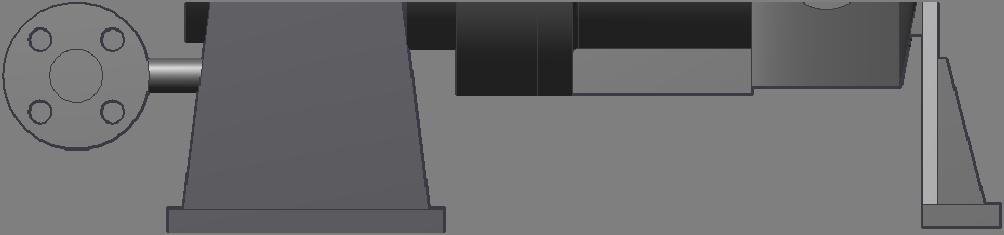
15 3. Description 3.6 Scope of supply Depending on the pump execution, the following items belong to the scope of supply: Pump Elastic coupling with spacer piece Coupling guard Welded base frame of sturdy design Drive motor Special accessories if required 3.7 Dimensions and Weights Dimensions and weights can be taken from the foundation plan / dimensional drawing. PRM E of 66


16 4. Handling / Storage / Disposal 4. Handling / Storage / Disposal 4.1 Handling DANGER Slipping of pump / pump unit from its suspension Danger of life through components falling down! Lift the pump / pump unit only in horizontal position. Never hook up the pump on its bare shaft. Never hang up the pump unit on the ring screw of the motor. Do not stay underneath floating loads. Consider weight indications on the dimensional drawing. Observe the local accident prevention regulations. Use suitable and approved lifting accessories. Fig. 4: lifting the pump NOTE The ring screw 919 shall be used as lifting device when handling the pump. Fig. 5: lifting the complete pump unit PRM E of 66
17 4. Handling / Storage / Disposal 4.2 Storage / Preservation ATTENTION Damage during storage through moisture or dirt. Corrosion and / or contamination of the pump! Outside storage requires a watertight cover over pump or over packed pump and accessories. ATTENTION Wetted, contaminated or damaged openings and joints. Leakage or damage of the pump! Plugged openings should be uncovered only during installation. The following measures are recommended for storage of the pump / pump unit: Store the pump in a sheltered dry place with constant air humidity. Turn the shaft manually once a month. New pumps of material GGG (ductile iron) and ferritic cast steel are covered inside with anti-corrosive agent and dewatering-fluid. The maximum dry storage period is 12 months. For storing a pump that has been in operation already, consider chapter Return of pump Drain the pump properly considering chapter 7.3. Rinse and clean the pump in general, especially when handling dangerous, explosive, hot or other risky liquids. A Document of Compliance completely filled in must always be attached to the pump. Refer to chapter NOTE If required, a Document of Compliance can be downloaded under PRM E of 66
18 4. Handling / Storage / Disposal 4.4 Disposal WARNING Liquids dangerous to health Danger for individuals and environment! Collect and dispose rinsing water and residual liquid. Wear protective clothing and face mask. Consider the legal regulations for disposal of liquids dangerous to health. 1. Disassemble pump / pump unit. 2. Collect grease and oil. 3. Separate pump materials 4. Dispose according to the local regulations. PRM E of 66
19 5. Installation / Mounting 5. Installation / Mounting 5.1 Safety Instructions DANGER Improper installation in explosive area Danger of explosion! Consider the local applicable explosion proof regulations. Consider indications on the pump data sheet and on the name tag of pump and motor. DANGER Strong magnetic field from the area of the magnet coupling or from single magnets Danger to life for individuals with pace maker! Disturbance on magnetic data media, electronic devices, components and instruments! Uncontrolled attractive force between magnetic components, tools etc.! A safe distance of 0,3 m minimum must be maintained. Consider additional notes in chapter Foundation WARNING Installation on weak and unstable foundations Personal injury and material damage! Consider sufficient concrete strength (minimum class XO) of the foundation acc. to DIN Place the pump unit on hardened foundation only. Place the pump unit on level and even surfaces only. Consider weight indications of dimensional drawing. PRM E of 66
20 5. Installation / Mounting 5.3 Installation of pump unit Installation on foundation 1. Place the pump unit on the foundation and align it with a water-level. Allowable deviation: 0,2 mm/m 2. Insert shims for height compensation. Always insert them both-sided near the foundation bolts between baseplate and foundation. 3. If the space between the foundation bolts is > 600 mm, insert additional shims in the middle between the foundation bolts. 4. All shims must seat solidly. 5. Hook the foundation bolts into the provided bore. 6. Concrete the foundation bolts. 7. Align the base plate after concrete has hardened. 8. Tighten the foundation bolts evenly. 9. Pour the base plate with vibration-free concrete of normal graining with a water-cement-value (W/Z-value) 0,5. Provide a pourable consistency by using a mobile solvent. Cure of concrete according to DIN Piping DANGER Exceedance of the allowable loads at the pump flanges Danger to life from leaking hot, toxic, caustic or flammable liquids. Do not use the pump as an anchor point for piping. Support piping before the pump and connect it stress-free. Consider allowable flange forces and moments according to chapter Compensate expansion of the piping in case of high temperatures. PRM E of 66
21 5. Installation / Mounting Suction pipe Layout of suction pipe requires special attention. NPSH Available and NPSH Required must be clearly defined. Pay attention to the following: Mounting of elbows close to the pump suction must be avoided. Provide a straight pipe of minimum two suction pipe diameters. Never connect a larger suction pipe direct to the pump. Flow eddies reduce the free flow area of the pump. Use an eccentric reducer, consider the figures below. Fig. 6: Flow eddies Fig. 7: Reducer connection At suction lift conditions, the suction pipe must continuously slope upwards towards pump suction. Avoid air pockets. At flooded suction conditions, the suction pipe must slope gradually downwards to the suction flange. Avoid air pockets to ensure a complete venting. Maximum flow speed of 2 m/s must not be exceeded. ATTENTION Welding beads, scale and other impurities in the piping. Damage of the pump! Piping must be thoroughly cleaned before connecting the pump. Remove impurities from the pipes. If required, insert a filter. NOTE Use a filter with a mesh width of 0,5 mm. Insert filter with a surface of minimum triple the pipe section. PRM E of 66
22 5. Installation / Mounting Allowable flange forces and moments Pump size Suction flange DN Fx [N] Fy [N] Fz [N] FR [N] Mx [Nm] My [Nm] Mz [Nm] MR [Nm] 26/ ½" / " / " / " / " / " / " / " / " / " / " Pump size Discharge flange DN Fx [N] Fy [N] Fz [N] FR [N] Mx [Nm] My [Nm] Mz [Nm] MR [Nm] 26/ " / ½" / ½" / " / " / " / " / " / " / " / " PRM E of 66
23 5. Installation / Mounting NOTE The pumps can tolerate double nozzle forces and moments as required by API Insulation WARNING Wetted casing parts adopt the temperature of the pumped liquid. Risk of burns! Insulate casing parts Attach protective device ATTENTION Heat accumulation in the bearing bracket Bearing damage! Do not insulate the bearing bracket 5.6 Coupling alignment DANGER Inadmissible temperatures on coupling or antifriction bearings due to misalignment of the coupling Danger of explosion! Proper alignment of coupling must anytime be ensured. WARNING Unintentional switch-on of the pump unit Risk of injury through moving components! Works on the pump unit may be done only with disconnected electricity. Secure the pump unit against unintentional switch-on. ATTENTION Offset of pump shaft and motor shaft Damage of pump, motor and coupling! Coupling check has always to be performed after pipe connection. Coupling check has also to be performed at pump units supplied on common base plate. PRM E of 66
24 5. Installation / Mounting Fig. 8: Angular and radial misalignment of couplings Fig. 9: Coupling alignment 1. Dismantle coupling guard. 2. Loosen support foot. 3. Place a straight edge (1) axially across the coupling half. 4. Possible radial displacement Kr becomes visible as a light gap. Better: Determine the radial misalignment by measuring the distances A and B at three points staggered by 120. The coupling is aligned correctly if the distance to the shaft is identical at all points. 5. Check the distance s 1 circularly between the coupling halves. The coupling is aligned correctly if the distance is circularly identical. 6. Concerning the allowable deviation s 1 and Kr of both coupling halves, refer to the instruction manual of the coupling manufacturer! 7. Mount the support foot. 8. Mount the coupling guard. PRM E of 66
25 5. Installation / Mounting 5.7 Alignment of pump and motor WARNING Exposed rotating coupling Risk of injury through rotating shaft! Operate the pump unit only with coupling guard. Select the coupling guard according to corresponding standards. DANGER Ignition hazard through friction sparks Danger of explosion! Use non-sparking material for coupling guard only to exclude flying sparks in case of contact. Consider EN After the pump unit is installed and piping is connected, check the coupling alignment and realign motor if necessary. Use shims for height compensation. 1. Dismantle coupling guard. 2. Check coupling alignment. Consider chapter Loosen hold down bolts of motor. 4. Place shims under the motor feet for height compensation. 5. Tighten hold down bolts of motor. 6. Check function of coupling / shaft. The coupling must easily be turnable by hand. 7. Mount the coupling guard. 8. Check the space between coupling and coupling guard. 5.8 Electrical connection of the pump unit DANGER Improper electrical installation Danger of explosion! Electrical installation requires additionally observance of IEC Explosion proof motors shall be connected through motor protection switch only DANGER Working on the pump unit by unqualified personnel Danger to life through electric shock! Electrical connection must be performed by qualified electrician only. Regulations IEC and IEC must be considered. PRM E of 66

26 5. Installation / Mounting WARNING Incorrect power connection Short circuit! Adhere to connection conditions of local energy supply companies. NOTE Star-Delta starting leads to a high torque increase when switching from star to delta, this can cause decoupling of the magnets. Therefore, star-delta starting is not suitable for magnetic coupled pumps. In order to reduce the starting current, a softstarter is recommended. Proceedings: 1. Check for compliance of the available supply voltage with the indications on the motor name tag. 2. Select suitable connection method. 3. Check for identical rotating direction of motor and pump. Consider the rotating direction arrow of the pump! NOTE Observe the instruction manual of the motor! Checking rotating direction DANGER Temperature rise through parts touching each other Danger of explosion! Never check rotating direction with dry pump. Disconnect the pump for checking rotating direction. ATTENTION Wrong rotating direction of motor and pump Damage of the pump! Consider the rotating direction arrow on the pump. 1. Start motor briefly. Note rotating direction of the motor. 2. Rotating direction of the motor must comply with the rotating direction arrow on the pump. 3. In case of wrong rotating direction, change the cables in the motor terminal box. PRM E of 66
27 6. Commissioning / Decommissioning 6. Commissioning / Decommissioning 6.1 Commissioning The following points must be checked prior to start-up; The pump unit is correctly electronically connected to all relevant protective devices. The pump is filled with liquid. Rotating direction has been checked. All additional connections are connected and fully functional. Lubricants are checked. After a longer standstill period, the measures mentioned in chapter 7 "Maintenance/Servicing/Inspection" must be considered and performed Filling of lubricant oil ATTENTION Lack of lube oil in the oil reservoir of constant level oiler Damage of antifriction bearings! Check oil level regularly. Oil level = centerline of sight glass Oil reservoir must always be sufficiently filled. Thread hole of constant level oiler must be horizontal Fig. 10: filling of bearing bracket 1. Unscrew vent plug (1). 2. Fold down the constant level oiler (2) away from bearing bracket (3) and hold it tight. 3. Fill in the oil through the vent plug bore (1) until the filling level reaches the connection pipe of the constant level oiler (2) PRM E of 66
28 6. Commissioning / Decommissioning 4. Fill up the oil reservoir to the maximum. 5. Fold back the constant level oiler (2) to its original position. 6. Screw in the vent plug (1). 7. Check the oil level in the oil reservoir of the constant level oiler (4) after a few minutes. Oil level = centerline of sight glass. If necessary, repeat steps 4 to 6. NOTE Exceeding oil level causes temperature increase or oil leakage. For filling quantity and oil quality refer to chapter Filling and venting the pump DANGER Formation of explosive atmosphere inside the pump Danger of explosion! The pump must permanently be filled with liquid. Appropriate monitoring measures must be provided. 1. Vent and fill up pump and suction pipe with liquid. Pump is selfventing. 2. Open shut-off valve in suction pipe completely 3. Open all additional connections completely (e.g. external circulation, external flush) PRM E of 66
29 6. Commissioning / Decommissioning Design with heating jacket Pump casing and/or containment shell with heating jacket. Permissible heating agent: Hot water Steam Heat transfer oil Pressure- and temperature limits: t max = 200 C p max = 25 bar ATTENTION Elevated surface temperature Danger of explosion! Consider the allowable temperature class. ATTENTION Lack of heating fluid Damage of the pump! Provide sufficient amount of heating fluid. ATTENTION Heating period too short Damage of the pump! Consider a sufficient heating period of the pump (approx. 2 hours) Check free rotation of the pump shaft. NOTE The area between sleeve bearings can be monitored with a PT100. ATTENTION Exceedance of the allowable heating fluid temperature Leak of pumped liquid or heating agent! Consider the application limits for pressure and temperature. PRM E of 66
30 6. Commissioning / Decommissioning Starting the pump DANGER Exceedance of allowable pressure- and temperature limits Danger of explosion! Leakage of hot or toxic liquid Never operate pump with closed shut-off valves in suction and/or discharge pipe. Start-up pump unit only against partially opened shut-off valve on discharge side. DANGER Elevated temperature through dry run Danger of explosion! Never operate pump in empty condition. Always fill up pump properly. Operate pump only within the allowable operating range. 1. Open shut-off valve completely in suction pipe 2. Open shut-off valve partially in discharge pipe 3. Switch on the motor. Pay attention to the synchronicity of pump and motor. Decoupling leads to low differential head and noise in the magnetic coupling. 4. When the pressure gauge indicates pressure, open shut-off valve on discharge side until the duty point is reached. 5. When the operating temperature is reached, check coupling alignment and realign if necessary. DANGER Elevated temperature through decoupling of the magnet coupling Danger of explosion! Switch off pump unit immediately. Eliminate cause of malfunction. 6.2 Operating the pump WARNING High surface temperatures through hot liquids Risk of burns! Avoid touching the pump surface. Wear protective clothing. ATTENTION Abnormal noises, vibrations, temperatures or leakage Damage of the pump! Switch off the pump immediately. Only restart the pump unit after cause of trouble has been eliminated. PRM E of 66
31 6. Commissioning / Decommissioning 6.3 Impeller trimming The impellers are hydraulically balanced in order to reduce the thrust load. Additional to the wear rings, thrust load balance is done individually or in combination with Back vanes Balancing holes Injection slots ATTENTION Improper impeller trimming Damage of sleeve bearing through incorrect thrust load balance! Impeller trimming shall be done only after consultation with Dickow Pumpen. 6.4 Operating limits DANGER Exceedance of operating limits regarding pressure, temperature and speed Danger of explosion! Leaking hot or toxic liquid! Maintain the allowable service conditions specified in the pump data sheet. Avoid operation against closed shut-off valve. Never operate pump at a temperature higher than specified in the pump data sheet Flow rate If not stated otherwise in the pump data sheet, the following applies: Q min = 0,25 x Q BEP Q max = 1,2 x Q BEP Switching frequencies DANGER Elevated surface temperature of the motor Danger of explosion! When using explosion proof motors, consider the information in the motor manual regarding switching frequencies. The switching frequencies are defined by the maximum temperature rise of the motor and depend on the power reserve of the motor during operation and on the starting conditions. PRM E of 66
32 6. Commissioning / Decommissioning NOTE Read instruction manual of motor manufacturer! Abrasive liquids or solids If products containing abrasive solids are handled, increased wear is expected. The inspection intervals in this regard must be shorter than the usual ones. ATTENTION Magnetic particles in the pumped liquid Damage of the magnet coupling! Take appropriate measures to keep the containment shell area free of magnetic particles. If magnet filter is used, provide differential pressure measurement 6.5 Switching off the pump 1. Keep shut-off valve in suction pipe open. 2. Close shut-off valve in discharge pipe. 3. Switch off the motor and watch for steady run down. NOTE In case a non-return valve is installed in the discharge pipe, the shut-off valve can remain open. A counter pressure must be available. For a longer standstill period, the following must be observed: Liquids which tend to polymerization, crystallization or solidification, must be drained completely. If required, rinse the pump with a suitable liquid. Close shut-off valve in the suction pipe. Flush connections must be closed. PRM E of 66
33 6. Commissioning / Decommissioning 6.6 Decommissioning The pump unit remains in the piping: Provide sufficient amount of liquid for the test runs. Switch on the pump unit regularly monthly or quarterly. The pump unit will be dismantled and stored: Empty the pump properly. Observe the safety instructions acc. to chapter 7.1 / 7.3. Spray the inside of the pump casing with preservation agent. Not required for stainless steel pumps. Spray preservation agent through suction and discharge flange. Plug suction and discharge flanges, e.g. with plastic caps. Lubricate all unpainted outside surfaces of the pump with oil and grease free of silicone. Not required for stainless steel pumps. Pay attention to additional notes in chapter 4.2. PRM E of 66
34 7. Maintenance / Servicing / Inspection 7. Maintenance / Servicing / Inspection 7.1 Safety regulations DANGER Improper maintained pump unit Danger of explosion! Maintain the pump unit regularly Establish a maintenance schedule DANGER Strong magnetic field in the area of magnet coupling or single magnets Danger to life for individuals with cardiac pacemakers! Disruption of magnetic data medium, electric devices, components and instruments! Uncontrolled attractive force between magnetic components, tools etc.! A safe distance of minimum 0,3 m must be maintained.. WARNING Unintentional switching-on of the pump unit Risk of injury through moving components! Works on the pump unit may be done only at disconnected electricity. Secure the pump unit against unintentional switch-on. WARNING Hot liquids Risk of injury! Let the pump unit cool down to ambient temperature. WARNING Liquids dangerous to health Risk of injury! Consider legal requirements. Take safety measures for individuals and environment when draining the pumped liquid. Decontaminate the pumps. The user must assure that maintenance, inspection and assembly is performed by qualified personnel. These persons must have studied this operating manual comprehensively. A maintenance schedule needs a minimum of effort and may avoid expensive repairs. Any use of force on the pump unit must be avoided. PRM E of 66
35 7. Maintenance / Servicing / Inspection 7.2 Operating surveillance DANGER Elevated surface temperature through hot running antifriction bearings Danger of explosion! Fire hazard! Check antifriction bearings regularly for running noise. Check the lubricant level regularly. ATTENTION Wear caused by dry run Damage of the pump! Never operate an empty pump. Never close the shut-off valve in suction pipe during operation. ATTENTION Exceedance of the allowable liquid temperature Damage of the pump! Operation against closed discharge valve is not allowed. Consider the temperature indications in the pump data sheet. The following requires regular checking during operation: The pump must always run steady and vibration-free. Check antifriction bearings for running noise. Vibrations, noises and increased power consumption are signs of wear. Check the elastic elements of the coupling. Clean the filter in the suction pipe regularly Lubrication / Lifetime of antifriction bearings DANGER Elevated surface temperature through hot running antifriction bearings or defective bearing seals Danger of explosion! Fire hazard! Check lubricant condition regularly. Check lubricant level regularly. Lubrication of antifriction bearings is normally provided by mineral oil. Lube oil CLP46 or 68 according to DIN or HD20W/20 with a kinematic viscosity of mm 2 /s at 40 C can be used, e.g. OMV lube EPX 46 Shell Morlina PRM E of 66
36 7. Maintenance / Servicing / Inspection The calculated lifetime of antifriction bearings is also under critical service conditions more than operating hours. The oil filling shall be renewed the first time after 200 operating hours, then once a year. Bearing frame Filling Qty [l] I 0,7 II 0,8 III 2,8 IV 1,2 NOTE If the ambient temperature is < -20 C DICKOW Pumpen should be consulted. Observe the comments in the pump data sheet Oil change 1. Place a suitable bowl for the waste oil underneath the drain plug. 2. Unscrew the drain plug from the bearing bracket and drain the oil. 3. After emptying, screw in the drain plug again. 4. Fill up oil again considering chapter WARNING Lubricating liquids dangerous to health Danger for individuals and environment! Draining requires safety measures for individuals and environment. Consider legal requirements concerning disposal of liquids dangerous to health Lubrication of sleeve bearings Sleeve bearings require a stable liquid film. Checking of wear must be done: after dry run or cavitation. when vibrations, noises and power consumption are increasing. PRM E of 66
37 7. Maintenance / Servicing / Inspection 7.3 Drainage and Disposal WARNING Pumped liquids dangerous to life Endangering for individuals and environment! Collect flushing liquid and possible residual liquid and dispose it. Wear protective clothing and face masks. Consider legal requirements concerning disposal of liquids. Drainage of pumped liquids through the drain plugs at the casing, through a connected shut-off valve or through a flange. Mode of drainage and position can be taken from the dimensional drawing! 7.4 Disassembly of pump unit General instructions Pay attention to safety instructions of chapter 7.1. Working on the motor requires observance of the documentation provided by the motor manufacturer. Consider the sectional drawings when disassembling. In case of damage, our service department can be contacted. DANGER Working on the pump unit without sufficient preparation Risk of injury! Switch off the pump unit properly. Close shut-off valves on suction and discharge side. Drain and depressurize the pump. Flush connections must be closed. Let the pump unit cool down to ambient temperature Removal of driver 1. Disconnect the motor. 2. Remove coupling guard. 3. Remove the hold down bolts of the motor from the baseplate. 4. Decouple pump and motor by displacing the motor. WARNING Tilting the motor Squeezing of hands and feet! Secure the motor by lifting or bracing. PRM E of 66


38 7. Maintenance / Servicing / Inspection NOTE If pump units are equipped with spacer type couplings, the motor can remain bolted to the baseplate while dismantling the interchangeable unit Tools ATTENTION Wrong disassembly and assembly tools Damage of components! Use special tools. In order to facilitate disassembly and assembly as well as to improve protection of sensitive components, the following special tools shall be used: Fig. 11: special tools frame 0 / I Fig. 12: special tools frame II Fig. 13: special tools frame III / IV Designation Dimensions / size / dwg.no. frame 0 / I frame II frame III / IV for part No. 1. Socket wrench / adapter unit (frame III) Disassembling sleeve Socket wrench (frame 0) (frame III) (frame I) (frame IV) Assembly tool / Puller incl. jack plate / / / Knipex-plier wrench 46 mm / 1 3/4" 46 mm / 1 3/4" 60 mm / 2 3/8" Inner hexagon cap screw M4 x Inner hexagon cap screw 3x M5 x 35 3x M5 x 35 2x M6 x Hex-wrench size 3, 4, 5, 6 size 4, 5, 6 size 4, 5, Flexible socket wrench 80 / 6 (frame IV) Inner hexagon cap screw 3x M5 x PRM E of 66
39 7. Maintenance / Servicing / Inspection Disassembly of rotating unit If spacer type couplings are used, the motor can remain bolted to the baseplate. Remove the spacer piece according to the operating instructions of the coupling manufacturer. Fig. 14: Disassembly of rotating unit 1. Loosen hexagon nut Loosen hexagon head bolt (1) from support foot Press the complete rotating unit (2) out off the volute casing Pull the rotating unit out off the casing and place it beside. 5. Pull off the coupling hub (3) from shaft end. WARNING Tilting the rotating unit Squeezing of hands and feet! Secure the rotating unit by lifting or bracing. PRM E of 66
40 7. Maintenance / Servicing / Inspection Disassembly of bearing bracket Fig. 15: Disassembly of bearing bracket 1. Remove the motor, consider chapter Remove the pump from the piping. 3. Place the pump in vertical position on a clean and even bench. 4. Remove hexagon nut from bearing housing Pull off the complete drive unit (1) by crane. Use of a ring screw (2) is recommended. 6. Place the drive unit in vertical position on a clean and even bench. WARNING Tilting the pump Squeezing of hands and feet! Secure the pump by lifting or bracing. ATTENTION Outer magnet is touching the containment shell Damage of containment shell or outer magnet! Use guide rods (3). PRM E of 66
41 7. Maintenance / Servicing / Inspection Disassembly of interchangeable unit The works according to chapter are completed. 1. Loosen hexagon nuts Press the complete interchangeable unit (= from impeller to containment shell) out off the volute casing 102 by using jack screws. 3. Pull the unit out off the casing and place it beside Disassembly of antifriction bearing The works according to chapter are completed. 1. Clamp the socket wrench / adapter unit see chapter in a jaw chuck. 2. Insert the bearing bracket unit with the drive shaft 213 into the adapter. 3. Attach the socket wrench see chapter to the shaft nut Remove the shaft nut (right hand thread). 5. Pull the drive rotor out off the bearing bracket unit and place it on a clean and even bench. WARNING Tilting the drive rotor and bearing bracket unit Squeezing of hands and feet! Secure the rotor- or bearing bracket unit by lifting or bracing. Fig. 16: Disassembly inner ring, roller bearing 6. Attach the puller (1) see chapter to the inner ring of the cylinder roller bearing and screw it tightly. Consider figure Fit the jack plate (2) see chapter Fit the puller (3) and pull off the inner ring of cylinder roller bearing. PRM E of 66
42 7. Maintenance / Servicing / Inspection 9. Fix the drive unit to the bench and secure it against twisting. 10. Remove key Loosen inner hexagon cap screws respectively hexagon head bolts (frame IV) and remove them together with bearing cover and labyrinth seal Press the drive shaft 213 with a press- or drilling spindle out off the bearing bracket 330. Frame size 0-III: Fig. 17: Disassembly shaft nut (frame. 0-III) 13. Reinsert key and press it in by a Knipex-plier wrench. 14. Clamp the drive shaft 213 in a jaw chuck. 15. Fit the socket wrench / adapter unit (1) to the shaft nut and loosen it by a ring spanner (2) (left hand thread). 16. Remove key Pull off the antifriction bearing 321 from drive shaft 213 using a puller. 18. Loosen inner hexagon cap screw and remove it together with bearing cover Press the outer ring of cylinder roller bearing 322 out off the bearing bracket seat. Frame IV: 13. Clamp the drive shaft 213 in a jaw chuck. 14. Loosen the inner hexagon cap screw in the shaft nut Remove the shaft nut using a ring spanner (left hand thread). 16. Pull off the antifriction bearing 321 from drive shaft using a puller. 17. Loosen the inner hexagon cap screw and remove it together with bearing cover Remove bearing bracket lantern Press the outer ring of cylinder roller bearing 322 out off the bearing bracket seat. PRM E of 66
43 7. Maintenance / Servicing / Inspection Replacing antifriction bearings Bearing bracket / I 6306 NU 308 C3 II 6307 NU 308 C3 III 6311 NU 2214 C3 IV 6311 NU Disassembly of impeller The works according to chapter are completed. 1. Clamp the impeller. 2. Loosen impeller nut 922 respectively inner hexagon cap screw (frame size 0) (right hand thread) 3. Pull off the impeller from pump shaft Disassembly of rotor and sleeve bearing The works according to chapter are completed. WARNING Possibly available residues of pumped liquid Danger for individuals and environment! Wear protective clothing. 1. Loosen and remove inner hexagon cap screws Loosen containment shell by jack screws. 3. Loosen hexagon nut Detach volute casing 102 from bearing housing 350 by using jack screws. 5. Disassemble impeller 233 according to chapter Fig. 18: Bearing frame 0 Fig. 19: Bearing frame I-III PRM E of 66
44 7. Maintenance / Servicing / Inspection 6. Remove key and pull off the start-up ring Pull the pump shaft unit out off the bearing housing unit. 8. Reinsert the key and press it in by using a Knipex-plier wrench. 9. Clamp the pump shaft unit in a jaw chuck. 10. Loosen the shaft nut by hook spanner (frame 0) respectively socket wrench (1) see chapter (left hand thread) 11. Pull off the rotor WARNING Axial magnetic forces Danger of squeezing fingers and hands! Use non-magnetic tools only. Never place the rotor near magnetic components. Fig. 20: Bearing housing unit 12. Loosen inner hexagon cap srews and remove casing cover Loosen inner hexagon cap screws Remove stationary sleeve bearings PRM E of 66
45 7. Maintenance / Servicing / Inspection Disassembly of shaft sleeve The works according to chapter are completed. WARNING Possibly available residues of pumped liquid Danger for individuals and environment! Wear protective clothing Fig. 21: Pump shaft unit Fig. 22: Disassembling sleeve 1. Clamp the pump shaft unit at the key in a jaw chuck. 2. Remove key with inner hexagon cap screw by a hex-wrench see chapter Pull off the start-up ring Fit the disassembling sleeve (1) see chapter to the shaft sleeve 524 and fasten it. 5. Fit the puller and remove the shaft sleeve. 6. Remove tolerance ring and intermediate ring Inspection Impeller / Wear ring The surfaces in the wear ring area may not have any visible grooves. Diameters of surfaces have to be measured. The total clearance in new condition is 0,6 mm. If the clearance exceeds 0,8 mm, the wear rings must be replaced. PRM E of 66
46 7. Maintenance / Servicing / Inspection Magnet assembly Driven rotor Surface must be free of cracks and bulges. Check parallelism by a bevelled steel edge. Drive rotor Replace outer magnets if mechanical or chemical damage is visible. Ball bearing seats must be measured, the rotor must be replaced if values fall below the following. frame 0/I 40,002 mm frame II 40,002 mm frame III 70,002 mm frame IV 70,002 mm Torque capacity Torques of new magnets are stated in the table below. Magnet length according to pump data sheet or name tag. For magnets that have been in operation a reduction of 10% is allowed. Larger reduction requires exchange of magnet coupling. Frame size 0 I / II II III IV SW Magnet length [mm] Torque [Nm] PRM E of 66
Operation / Installation Instructions NKLs No. 44.NKLs.E2.10/14 DICKOW PUMPEN KG
 Operation / Installation Instructions NKLs No. 44.NKLs.E2.10/14 DICKOW PUMPEN KG Original Manual Table of Contents Table of Contents Table of Contents... 2 1. General... 4 2. SAFETY... 5 2.1 Designation
Operating / Installation Instructions SCMR. No. 44.SCMR.E3.06/13. valid from pump serial No. PB onwards. Original manual DICKOW PUMPEN KG
 Operating / Installation Instructions SCMR No. 44.SCMR.E3.06/13 valid from pump serial No. PB12198400 onwards DICKOW PUMPEN KG Original manual Table of Contents Table of Contents Table of Contents... 2
Operation / Installation Instructions NCR. No. 44.NCR.E3.04/11. Original Manual DICKOW PUMPEN KG
 Operation / Installation Instructions NCR No. 44.NCR.E3.04/11 DICKOW PUMPEN KG Original Manual Table of Contents Table of Contents Table of Contents... 2 1. General... 4 2. Safety... 5 2.1 Designation
Sealless Magnetic Coupled Hot Oil Circulation Pumps acc. to DIN EN / ISO 2858 Type NMWR / NMWB / NMW. our. contribution for
 Sealless Magnetic Coupled Hot Oil Circulation Pumps acc. to DIN EN 22858 / ISO 2858 Type NMWR / NMWB / NMW our contribution for environmental protection General DICKOW pumps of series NMWR / NMWB / NMW
our contribution for Sealless Magnetic Coupled Multistage Centrifugal Pumps Type HZM / HZMR / HZMB environmental protection
 Sealless Magnetic Coupled Multistage Centrifugal Pumps Type HZM / HZMR / HZMB our contribution for environmental protection General DICKOW-pumps of series HZM are sealless multistage horizontal centrifugal
Sealless Magnetic Coupled Multistage Centrifugal Pumps with Priming Stage Type HZSM / HZSMB / HZSMR / HZSMA / HZSMAR
 Sealless Magnetic Coupled Multistage Centrifugal Pumps with Priming Stage Type HZSM / HZSMB / HZSMR / HZSMA / HZSMAR our contribution for environmental protection General DICKOW-pumps of series HZSM are
Sealless magnetic coupled centrifugal pump Type NMR Design with heavy duty oil lubricated bearing bracket. our. contribution for
 Sealless magnetic coupled centrifugal pump Type NMR Design with heavy duty oil lubricated bearing bracket our contribution for environmental protection GENERAL DICKOW-pumps of series NMR are sealless centrifugal
our contribution for environmental protection Sealless magnetic coupled centrifugal pumps acc. to EN Type NML / NMB
 Sealless magnetic coupled centrifugal pumps acc. to EN 22858 our contribution for environmental protection Type NML / NMB General Magnetic coupled DICKOW-pumps of the series NM are sealless pumps. The
SPECIFY THE RIGHT HOT OIL PUMP FOR YOUR APPLICATION
 SPECIFY THE RIGHT HOT OIL PUMP FOR YOUR APPLICATION Hot oil pumps are used in a range of industries, with their main user being the heat transfer oil customer. Often, oil temperatures will exceed 500 F
our contribution for Sealless Magnetic Coupled Multistage Centrifugal Pumps Type HZM / HZMR / HZMB environmental protection
 Sealless Magnetic Coupled Multistage Centrifugal Pumps Type HZM / HZMR / HZMB our contribution for environmental protection General DICKOW-pumps of series HZM are sealless multistage horizontal centrifugal
SERIES PC INSTRUCTION AND OPERATION MANUAL
 MEGGA SERIES PC INSTRUCTION AND OPERATION MANUAL Models PCT and PCF Close-coupled and frame-mounted single-stage horizontal end-suction pumps. WARNING: Read this manual before installing or operating this
INSTALLATION, OPERATION AND MAINTENANCE INSTRUCTIONS
 INSTALLATION, OPERATION AND MAINTENANCE INSTRUCTIONS Contents Section 1. General Observations... 2 2. Operation... 4 3. Control During Operation... 5 4. Trouble Shooting... 6 5. Maintenance... 7 Please
Operating Instructions
 Operating Instructions BE2700 Brinkmann Immersions pumps of the series TA/STA/TAL/SAL901... 1303 Contents 1 General...1 2 Safety...2 3 Transport and storage...2 4 Description of product and accessories...2
Volute Casing Centrifugal Pumps in High Temperature Design with Magnetic Drive. Series CNH-ML
 Volute Casing Centrifugal Pumps in High Temperature Design with Magnetic Drive Series CNH-ML Usage For pumping toxic, volatile, explosive or other fluids harmful to the environment which call for service
Dry installed pump type LANDY BTP.
 OPERATION & MAINTENANCE MANUAL Dry installed pump type LANDY BTP. Landustrie Sneek BV Pieter Zeemanstraat 6 Tel. 0031 515-486888 P.O. BOX 199 Fax. 0031 515-412398 NL-8600 AD Sneek info@landustrie.nl The
Mounting and Operating Instructions EB 8135/8136 EN. Series V2001 Valves Type 3535 Three-way Valve for Heat Transfer Oil
 Series V2001 Valves Type 3535 Three-way Valve for Heat Transfer Oil Type 3535 Three-way Valve with bellows seal and rod-type yoke (partial view) Mounting and Operating Instructions EB 8135/8136 EN Edition
Pressure relief valve
 Pressure relief valve Operating manual Series DHV 712 Version BA-2015.10.20 EN Print-No. 300 510 TR MA DE Rev001 ASV Stübbe GmbH & Co. KG Hollwieser Straße 5 32602 Vlotho Germany Phone: +49 (0) 5733-799-0
HTM Circulation Pumps acc. to DIN EN 733 Type NKLs
 HTM Circulation Pumps acc. to DIN EN 733 Type NKLs General The DICKOW standard HTM pumps, series NKLs according to EN 733, are designed as centrifugal pumps of light duty for handling heat transfer media.
Installation and Operating Instructions for EAS -NC clutch Type 45_. _. _ Sizes 02 and 03
 Table of contents: Please read and observe this Operating Instruction carefully! A possible malfunction or failure of the clutch and any damage may be caused by not observing it. Page 1: - Table of contents
This manual presents installation, servicing, troubleshooting, and maintenance for M PUMPS CM MAG-M SERIES Information that may be required regarding
 Installation, Operating, Maintenance & Safety Instruction for M PUMPS CM MAG-M SERIES Centrifugal light Mag-Drive pumps (CM MAG-M06/1/2/3/4) This manual presents installation, servicing, troubleshooting,
Volute Casing Centrifugal Pumps PN 16 for heat-transfer liquids Heat-transfer oil up to 350 C Hot water up to183 C
 Volute Casing Centrifugal Pumps PN 16 for heat-transfer liquids Heat-transfer oil up to 350 C Hot water up to183 C Series CMIT in inline design Series CMAT with axial inlet ATEX 0 a Series CMAT Series
Operating Instruction
 Operating Instruction Drive element LEWA - ecosmart type LCA with manual stroke adjustment, motor mounted vertically Table of contents 1 General information / safety 1.1 Important preliminary information
FLENDER ZAPEX couplings. Type ZWT. Operating instructions BA 3505 EN 10/2011. FLENDER couplings
 FLENDER ZAPEX couplings Type ZWT Operating instructions FLENDER couplings FLENDER ZAPEX couplings Type ZWT Operating instructions Translation of the original operating instructions Technical data Notes
Series Base mounted pump. Installation and operating instructions
 Series 4030 Installation and File No: 40.80 Date: june 25, 2015 Supersedes: 40.80 Date: october 10, 2009 contents General 4 Inspection 4 Installation - Series 4030 base mounted Pump 4 1.0 Location 4 2.0
HEAVY DUTY HORIZONTAL, SEALLESS CENTRIFUGAL PUMP WITH PERMANENT MAGNET DRIVE SYSTEM, NO MECHANICAL SEAL ISO DIN 24256
 HEAVY DUTY HORIZONTAL, SEALLESS CENTRIFUGAL PUMP WITH PERMANENT MAGNET DRIVE SYSTEM, NO MECHANICAL SEAL ISO 2858 - DIN 24256 CN MAG-M Series The separation of liquid chamber/atmosphere by means of an isolation
Volute Casing Centrifugal Pumps in In-line Design with Magnetic Drive. Series CNI-M
 Volute Casing Centrifugal Pumps in In-line Design with Magnetic Drive Series CNI-M Usage For pumping toxic, volatile, explosive or other fluids harmful to the environment which call for service of hermetically
Multistage Submerged Centrifugal Pump Type HZV
 Multistage Submerged Centrifugal Pump Type HZV GENERAL, FIELD OF APPLICATION The DICKOW vertical submersible long shaft pump is a one or multistage centrifugal pump. The performance range covers capacities
SERIES G3DB/AG3DB ELEVATOR
 TM INSTRUCTIONS AND PARTS LIST SERIES G3DB/AG3DB ELEVATOR WARNING This manual, and GENERAL INSTRUCTIONS MANUAL, CA-1, should be read thoroughly prior to pump installation, operation or maintenance. SRM00059
Medium and high pressure pumps
 Screw pumps Medium and high pressure pumps Installation and Start-up Instruction This instruction is valid for all standard high pressure pumps: E4, D4 and D6 Contents Page Pump identification 2 Installation
Operating & Maintenance Manual For Steam Conditioning Valve
 For Steam Conditioning Valve 1 Table of Contents 1.0 Introduction 3 2.0 Product description 3 3.0 Safety Instruction 4 4.0 Installation and Commissioning 5 5.0 Valve Disassembly 6 6.0 Maintenance 6 7.0
IMPORTANT SAFETY NOTICE
 IMPORTANT SAFETY NOTICE To: Our Valued Customers User safety is a major focus in the design of our products. Following the precautions outlined in this manual will minimize your risk of injury. ITT Goulds
Service Manual #67. Installation and Service Instructions 6000, 7000 & 8000 Series Magnetically Coupled Pumps
 Service Manual #67 Installation and Service Instructions 6000, 7000 & 8000 Series Magnetically Coupled Pumps Table of Contents Section Description Page 1 General Description 4 2 The Pumping Principle 5
Instruction Manual. Sewage lifting station compli 300
 Instruction Manual Sewage lifting station compli 300 Safety instructions Areas of application Electrical connection Installation Servicing Technical data Appendix JUNG PUMPEN GmbH Industriestr. 4-6 33803
Volute Casing Centrifugal Pumps according to EN 22858, ISO 2858 with Magnetic Drive. Series CNH-M
 Volute Casing Centrifugal Pumps according to EN 22858, ISO 2858 with Magnetic Drive Series CNH-M Usage For pumping toxic, volatile, explosive or other fluids harmful to the environment which call for service
CONTENTS. VIKING PUMP, INC. A Unit of IDEX Corporation Cedar Falls, IA USA SECTION TSM 710.1
 TECHNICAL SERVICE MANUAL industrial heavy duty motor speed pumps SERIES 4076 AND 4176 SIZES hle, ate and ale SECTION TSM 710.1 PAGE 1 of 8 ISSUE B CONTENTS Introduction....................... 1 Safety
NEOTECHA NTB-NTC BALL VALVES INSTALLATION AND MAINTENANCE INSTRUCTIONS
 Before installation these instructions must be fully read and understood 2 SAFETY Please also read through these notes carefully. 2.1 General potential danger due to: a. Failure to observe the instructions
Operation and Maintenance Manual Magnetic Drive Sealless Pumps MAXP SERIES
 Operation and Maintenance Manual Magnetic Drive Sealless Pumps MAXP SERIES Magnatex Pumps, Inc. 3575 West 12th Street Houston, TX 77008 Toll Free: 866.MAG.PUMP Phone:713.972.8666 Fax:713.972.8665 www.magnatexpumps.com
Operating Instructions for Elevator Buffers type LP
 Operating Instructions for Elevator Buffers type LP 1 Scope of application The Elevator Buffer type LP is an energy dissipation type buffer according to EN 81-1/2, EN 81-20, EN 81-50 5.5 and therefore
Assembly and Maintenance Manual Type ASNU
 Assembly and Maintenance Manual Type ASNU Hatschekstr.36 69126 Heidelberg Germany Tel +49(0)6221 30470 Fax +49(0)6221 304731 info@stieber.de www.stieber.de Date of issue: 30.05.2018 GB Revision: 0 U:\EngUsers\!ProduktDoku\1AAA_Einbauerklaerung_Wartungsanleitung_Konformitaetserklaerung\1AAA_Wartungsanleitungen\Orginal_Worddatei\_ASNU.docx
Submersible Long Shaft Pumps for the Chemical Industry Type NCT/NMT
 Submersible Long Shaft Pumps for the Chemical Industry Type NCT/NMT General The DICKOW submersible pump, type NCT, for the chemical industry is a vertical pump with separate discharge pipe. The maximum
These installation and maintenance instructions must be read in full and completely understood before the installation!
 These installation and maintenance instructions must be read in full and completely understood before the installation! 1. General information on the installation and maintenance instructions These instructions
Mounting and Operating Instructions EB 8039 EN. Type 3351 Pneumatic On/off Valve. Type 3351 Pneumatic On/off Valve. Type 3351 Pneumatic On/off Valve
 Type 3351 Pneumatic On/off Valve Type 3351 Pneumatic On/off Valve Type 3351 Pneumatic On/off Valve Version with handwheel Mounting and Operating Instructions EB 8039 EN Edition May 2016 Definition of signal
SERVO MOTORS BRUSHLESS SERVO MOTORS OPERATING INSTRUCTIONS 2016
 SERVO MOTORS BRUSHLESS SERVO MOTORS OPERATING INSTRUCTIONS 2016 3009/16 en Ed.02.2016 Read these Operating Instructions before performing any transportation, installation, commissioning, maintenance or
INSTRUCTION MANUAL AND PARTS LIST FOR 3SIC AND 4SIC SERIES PUMPS
 TM INSTRUCTION MANUAL AND PARTS LIST FOR 3SIC AND 4SIC SERIES PUMPS WARNING This manual, and General Instructions Manual, CA-1 should be read thoroughly prior to pump installation, operation or maintenance.
INSTRUCTION MANUAL. I/P Converter DSG BXXY3Z DSG BXXY4Z
 INSTRUCTION MANUAL I/P Converter DSG BXXY3Z DSG BXXY4Z Revision 2.0 3.626 016136 en Page 1/15 Should you have any questions concerning the I/P converter, please contact the Service Department of the Product
D58 Series Brake Instructions
 D58 Series Brake Instructions 4740 W. Electric Avenue Milwaukee, WI 53219 414/672-7830 FAX 414/672-5354 www. dingsbrakes.com Safety information 2 Safety information 2.1 Persons responsible for the safety
Electropneumatic Converters i/p Converters Type 6111 Mounting and Operating Instructions EB 6111 EN
 Electropneumatic Converters i/p Converters Type 6111 Fig. 1 Type 6111 in standard version Fig. Type 6111 mounted on a supply air manifold Fig. 3 Type 6111 in field enclosure Mounting and Operating Instructions
Series Base mounted pump. Installation and operating instructions
 Series 4030 Installation and File No: 40.80 Date: december 12, 2016 Supersedes: 40.80 Date: july 27, 2016 contents General 4 Inspection 4 Installation - Series 4030 base mounted Pump 4 1.0 Location 4
Operating Instruction for Liquid-Ring Vacuum Pumps
 Operating Instruction for Liquid-Ring Vacuum Pumps Serial No Type EDUR-Pumpenfabrik Eduard Redlien GmbH & Co. KG Postfach 1949 D-24018 Kiel Tel. (+431) 689868 Fax (+431) 6898800 E-mail: info@edur.de http://www.edur.de
Mounting and Operating Instructions EB 8222 EN. Type 3310/AT and Type 3310/3278 Pneumatic Control Valves. Type 3310 Segmented Ball Valve
 Type 3310/AT and Type 3310/3278 Pneumatic Control Valves Type 3310 Segmented Ball Valve Fig. 1 Type 3310/3278 with positioner Fig. 2 Type 3310/AT Mounting and Operating Instructions EB 8222 EN Edition
Assembly and Maintenance Manual Type AS
 Assembly and Maintenance Manual Type AS Hatschekstr.36 69126 Heidelberg Germany Tel +49(0)6221 30470 Fax +49(0)6221 304731 info@stieber.de www.stieber.de Date of issue: 30.05.2018 GB Revision: 0 U:\EngUsers\!ProduktDoku\1AAA_Einbauerklaerung_Wartungsanleitung_Konformitaetserklaerung\1AAA_Wartungsanleitungen\Orginal_Worddatei\_AS.docx
PRODUCT SERVICE MANUAL FOR BK12DHZ PUMPS
 PRODUCT SERVICE MANUAL FOR BK12DHZ PUMPS WARNING This manual, and the GENERAL INSTRUCTION MANUAL SRM00046, should be read thoroughly prior to pump installation, operation or maintenance. Manual No. SRM00095
Standardised Water Pump. Etanorm. Installation/Operating Manual
 Standardised Water Pump Etanorm Installation/Operating Manual Legal information/copyright Installation/Operating Manual Etanorm Original operating manual All rights reserved. The contents provided herein
TP300 INDUSTRIAL TRASH PUMP OPERATOR S MANUAL
 TP300 INDUSTRIAL TRASH PUMP OPERATOR S MANUAL IT IS EXTREMELY IMPORTANT TO READ AND UNDERSTAND THE ENTIRE CONTENTS OF THIS OPERATOR S MANUAL BEFORE ATTEMPTING TO OPERATE THE PRODUCT. THIS EQUIPMENT IS
PN 16 Volute Centrifugal Pumps (depending on materials up to PN 25) according to EN 22858/ISO 2858 and EN ISO 5199
 according to EN 22858/ISO 2858 and EN ISO 5199") PN 16 Volute Centrifugal Pumps (depending on materials up to PN 25) according to EN 22858/ISO 2858 and EN ISO 5199 Utilization Used to pump non-aggressive or aggressive liquids, cold or hot liquids, clean
PN 16 Volute Centrifugal Pumps (depending on materials up to PN 25) according to EN 22858/ISO 2858 and EN ISO 5199 Utilization Used to pump non-aggressive or aggressive liquids, cold or hot liquids, clean
OPERATING MANUAL. Black Bruin hydraulic motors S-series model D
 S-series model D CONTENTS 1 GENERAL INSTRUCTIONS... 3 1.1 About the manual... 3 1.2 Revision comments... 3 1.3 Applicability... 3 1.4 Warranty... 3 1.5 Product identification... 3 2 INSTALLATION INSTRUCTIONS...
Mounting and Operating Instructions EB 8091 EN. Pneumatic Control Valve Type and Type Type with 120 cm 2 actuator
 Pneumatic Control Valve Type 3510-1 and Type 3510-7 Type 3510-1 with 120 cm 2 actuator Type 3510-7 with 120 cm 2 actuator and integrated positioner Type 3510-1 with 60 cm 2 actuator Fig. 1 Pneumatic control
RADEX -N Composite Operating/Assembly instructions
 1 of 14 RADEX -N is a torsionally stiff flexible steel lamina coupling. It is able to compensate for shaft misalignment, for example caused by thermal expansion, etc. note ISO 101. Drawn: 0.05.15 Kb/Wig
1 Mounting V-belt drive (motor pulley, fly wheel, V-belts and guard)
") Mounting V-belt drive (motor pulley, fly wheel, V-belts and guard) General safety instructions, requirements and procedures 1 Mounting V-belt drive (motor pulley, fly wheel, V-belts and guard) 1.1 General
Mounting V-belt drive (motor pulley, fly wheel, V-belts and guard) General safety instructions, requirements and procedures 1 Mounting V-belt drive (motor pulley, fly wheel, V-belts and guard) 1.1 General
Installation, Operation, and Maintenance Manual
 Industrial Process Installation, Operation, and Maintenance Manual Cam-Tite Ball Valve Table of Contents Table of Contents Introduction and Safety...2 Safety message levels...2 User health and safety...2
Chemical Magnetic Pumps with PTFE/PFA lining ATEX- and FDA compliant
 Chemical Magnetic Pumps with PTFE/PFA lining ATEX- and FDA compliant Highly corrosionresistant pumps for absolute aggressive liquids and dangerous liquids. Energy-efficient pumps and chemical pumps Sustainable
Installation, Operation, and Maintenance Manual
 Industrial Process Installation, Operation, and Maintenance Manual Series PBFV Plastic Lined Butterfly Valve - Lug and Wafer Style Table of Contents Table of Contents Introduction and Safety...2 Safety
Installation and Operational Instructions for EAS - HTL housed overload clutch Sizes 01 3 Type 490._24.0
 Please read these Operational Instructions carefully and follow them accordingly! Ignoring these Instructions may lead to malfunctions or to clutch failure, resulting in damage to other parts. Contents:
Operation & Maintenance Manual
 Operation & Maintenance Manual Submersible pumps type LANDY DTP. Landustrie Sneek BV Tel. +31 515-486888 Pieter Zeemanstraat 6 Fax +31 515-412398 P. O. Box 199 info@landustrie.nl 8600 AD Sneek, Holland
Installation and Operating Manual for Tank and Equipment Cleaning Nozzles Series 5TM
 Installation and Operating Manual for Tank and Equipment Cleaning Nozzles Series 5TM 150 150 150 This instruction manual contains proprietary information which is protected by copyright laws. No part of
Storage, operating and maintenance instructions for AZ plug valves and Standard valves
 ARMATUREN Plug - Valves metallic with PTFE Sleeve 2-7 way Storage, operating and maintenance instructions for AZ plug valves and Standard valves Plug - Valves FEP/PFA - lined, 2-3 way Butterfly - Valves
INSTRUCTION MANUAL AND PARTS LIST FOR PG/RG3D_-187, 218, 250 and 312 SERIES PUMPS
 INSTRUCTION MANUAL AND PARTS LIST FOR PG/RG3D_-187, 218, 250 and 312 SERIES PUMPS WARNING This Instruction Manual and General Instructions Manual, CA-1, should be read thoroughly prior to pump installation,
Bearing Handling. 15. Bearing Handling Bearing storage Installation
 15. Bearing Handling Bearings are precision parts and, in order to preserve their accuracy and reliability, care must be exercised in their handling. In particular, bearing cleanliness must be maintained,
Globe Valve Type Fig. 1 Type 3241 Globe Valve. Mounting and Operating Instructions EB EN
 Globe Valve Type 3241 Fig. 1 Type 3241 Globe Valve Mounting and Operating Instructions EB 8015-1 EN Edition July 2012 Contents Contents Page 1 Design and principle of operation.................... 4 2
Assembly and Maintenance Manual Type RSBW
 Assembly and Maintenance Manual Type RSBW Hatschekstr. 36 69126 Heidelberg Germany Tel +49(0)6221 30470 Tel +49(0)6221 304731 info@stieber.de www.stieber.de Stieber Clutch Date of issue: 16/03/2017 GB
Installation, Operation, and Maintenance Manual
 Industrial Process Installation, Operation, and Maintenance Manual Series PBV Plastic Lined Ball Valve Table of Contents Table of Contents Introduction and Safety...2 Safety message levels...2 User health
MODEL INFORMATION CANNED MOTOR PUMP TYPE CAM HERMETIC
 MODEL INFORMATION CANNED MOTOR PUMP TYPE CAM HERMETIC ... 3... 4 3000 rpm 50 Hz / 3600 rpm 60 Hz... 4... 5... 7 Modular pump / motor systems... 7 Materials...........................................................
CSO / CP PUMPS Vertical Spindle Type Installation, Operation and Maintenance Manual
 CSO / CP PUMPS Vertical Spindle Type Installation, Operation and Maintenance Manual www.sameng.co.za (011) 823 4250 Proud Manufacturers of SAMCO Pumps Contents INTRODUCTION 3 LOCATION OF UNIT 3 INSTALLATION
Declaration of Conformity as per Directive 97/23/EC
 Declaration of Conformity as per Directive 97/23/EC The manufacturer declares that:, 47906 Kempen, Germany PTFE-lined Rotary plug valves Series 23e, with packing with lever for 90 operation with worm gear
WMTA6 LN SERIES SEAL-LESS MAG-DRIVE MULTI-STAGE TURBINE PUMPS
 WMTA6 LN SERIES SEAL-LESS MAG-DRIVE MULTI-STAGE TURBINE PUMPS INSTALLATION, OPERATION, AND MAINTENANCE INSTRUCTIONS TO OBTAIN THE BEST PERFORMANCE FROM YOUR WARRENDER WMTA6 LN PUMP, PLEASE READ THIS MANUAL
PROJ. NO SECTION HYDRONIC PUMPS
 SECTION 23 21 23 HYDRONIC PUMPS PART 1 - GENERAL 1.1 RELATED DOCUMENTS A. Drawings and general provisions of the Contract, including General and Supplementary Conditions and Division 01 Specification Sections,
Operating and Maintenance Instructions. Abteilung TB, Schell Seite 1 8 SERIES 56
 Abteilung TB, Schell Seite 1 8 These instructions supersede all earlier instructions, in particular BWS 109-0 till BWS 109-3. For applications in areas with explosion hazard it is obligatory to observe
INSTRUCTION MANUAL INTERNAL GEAR PUMP TITAN G-4124A SERIES=> FLANGED TITAN G-124A SERIES => FLANGED MODELS:
 INSTRUCTION MANUAL INTERNAL GEAR PUMP TITAN G-4124A SERIES=> FLANGED TITAN G-124A SERIES => FLANGED MODELS: G-H, G-HL, G-K, G-KK, G-L, G-LQ, G-LL, GLS, G-Q, G-QS 1 Contents Maintenance Thrust bearing adjustment
PRODUCT SERVICE MANUAL. BK6DHZ(C)-250, 275, 312 and 400 PUMPS
-250, 275, 312 and 400 PUMPS") PRODUCT SERVICE MANUAL BK6DHZ(C)-250, 275, 312 and 400 PUMPS WARNING This manual, and the GENERAL INSTRUCTION MANUAL, SRM00046, should be read thoroughly prior to pump installation, operation or maintenance.
PRODUCT SERVICE MANUAL BK6DHZ(C)-250, 275, 312 and 400 PUMPS WARNING This manual, and the GENERAL INSTRUCTION MANUAL, SRM00046, should be read thoroughly prior to pump installation, operation or maintenance.
X.. Series Helical and Bevel-Helical Gear Units
 SEW-EURODRIVE Easy Guide Industrial Gear Units X.. Series Helical and Bevel-Helical Gear Units Edition 05/2018 24803731/ EN 2/16 Gear unit structure 1 Safety notes 2 Gear unit designs 3 Mounting positions
Operating Instructions Flexdip CYA112
 BA00432C/07/EN/13.13 71207066 Products Solutions Services Operating Instructions Wastewater assembly About this document Safety messages The structure, signal words and safety colors of the signs comply
User Guide. Lubricus Lubrication System LUB-D1/LUB-D2/LUB-D3/LUB-D4 (24 VDC)
") User Guide Lubricus Lubrication System LUB-D1/LUB-D2/LUB-D3/LUB-D4 (24 VDC) version 04/2013 Content General Information 3 Warning 3 Scope of Supply 3 Overview 3 General safety details 4 Intended use 4
User Guide Lubricus Lubrication System LUB-D1/LUB-D2/LUB-D3/LUB-D4 (24 VDC) version 04/2013 Content General Information 3 Warning 3 Scope of Supply 3 Overview 3 General safety details 4 Intended use 4
OPERATING MANUAL. Black Bruin Hydraulic Rotators
 OPERATING MANUAL All information given in this manual is current and valid according to the information available at the time of publication. Sampo Hydraulics Ltd. reserves the rights to implement changes
26 Series Stainless Steel 2-way Ball Valves
 1-800-899-0553 26 Series Stainless Steel 2-way Ball Valves Users Manual Installation, Operation, & Maintenance 1. General Precaution 1.1. Material Section Material deterioration is determined by the contained
Type Operating Instructions. Bedienungsanleitung Manuel d utilisation
 Globe control valve, pneumatically operated Actuator sizes 40 mm - 125 mm, Nominal diameter DN10-65 Kolbengesteuertes Geradsitzventil Antriebsgrößen 40 mm - 125 mm, Nennweiten DN10-65 Vanne à siège droit
Mounting and Operating Instructions EB 5868/5869 EN
 Electric Control Valves Types 3213/5857, 3213/5824, Types 3214/5824, 3214/3374, 3214/3274 with safety function: Types 3213/5825, 3214/5825, 3214/3374, 3214/3274 Pneumatic Control Valves Types 3213/2780-1,
Norm-Centrifugal Pumps PN 10
 Norm-Centrifugal Pumps PN 10 Pump dimensions acc. to DIN EN 733 with additional sizes Technical requirements acc. to DIN ISO 9908 Application For pumping pure water, industrial water, sea water, condensate,
TECHNICAL SERVICE MANUAL
 Electronic copies of the most current TSM issue can be found on the Viking Pump website at www.vikingpump.com TECHNICAL SERVICE MANUAL industrial heavy duty motor speed pumps SERIES 4076 AND 4176 SIZES
SEMA Side channel pumps PN 25 (40) Glandless because of magnetic drive
 Glandless because of magnetic drive") SEMA Side channel pumps PN 25 (40) Glandless because of magnetic drive SEMA-S SEMA-L with reference to DIN EN 734 SEMA-Z with reference to DIN EN 734 SEMA-Block in closed-coupled design for extremely low
SEMA Side channel pumps PN 25 (40) Glandless because of magnetic drive SEMA-S SEMA-L with reference to DIN EN 734 SEMA-Z with reference to DIN EN 734 SEMA-Block in closed-coupled design for extremely low
Printed: Doc-Nr: PUB / / 000 / 00
 ORIGINAL OPERATING INSTRUCTIONS Hilti HTE-P 33 dispenser It is essential that the operating instructions are read before the tool is operated for the first time. Always keep these operating instructions
Standardised Chemical Pump. MegaCPK. Installation/Operating Manual
 Standardised Chemical Pump MegaCPK Installation/Operating Manual Legal information/copyright Installation/Operating Manual MegaCPK Original operating manual KSB Aktiengesellschaft All rights reserved.
Standard Chemical Pump
 Standard Chemical Pump Operating instructions MPC-B series Version BA-2006.03 Print-No. 01 VM-No. EN Munsch Chemie-Pumpen GmbH Im Staudchen 56235 Ransbach-Baumbach Germany Phone: +49 (0) 26 23-8 98-90
original operating manual Operating manual Translation of the Item-No.: ,
 Translation of the original operating manual Operating manual Item-No.: 015 431 551, 015 431 581 Important! Copyright The operating manual is always to be read before commissioning the equipment. No warranty
Operation Manual. for. Centrifugal Pumps Type SLM AHO. Execution acc. to Directive 94/9/EC
 Operation Manual for Centrifugal Pumps Type SLM AHO Execution acc. to Directive 94/9/EC BA/EN-33910-Coversheet-00.doc Contents of Operation Manual 1. General BA/EN-33910-01/.. 2. Safety BA/EN-21900-02/..
Operating / Assembly Instructions Type A and CS Coupling
 Page: 1 of 14 Subject Index 1. Technical Data 2. Hints 2.1. General Hints 2.2. Warning and Safety Hints. 2.3. General Hints to Danger. 2.4. Proper use. 3. Storage. 4. Assembly. 4.1. Coupling components.
A408 GB. Pneumatic oil and diesel pumps 1:1
 03 594 A408 GB Pneumatic oil and diesel pumps 1:1 G Operating instructions for Pneumatic oil and diesel pump 1:1 Contents 1. General details 2 1.1 Intended use 2 1.2 Design and functional description 2
BoWex FLE-PA. BoWex FLE-PAC. KTR-N Sheet: Edition: EN 1 of BoWex FLE-PA / FLE-PAC Operating/Assembly instructions
 1 of 17 is a torsionally rigid flange coupling. It is able to compensate for shaft misalignment, for example caused by manufacturing inaccuracies, thermal expansion, etc. BoWex FLE-PA BoWex FLE-PAC Drawn:
Maintenance Information
 16573370 Edition 2 February 2014 Air Grinder 99V Series Maintenance Information Save These Instructions Product Safety Information WARNING Failure to observe the following warnings, and to avoid these
Vertical Shaft Submersible Pump for the Chemical Industry CTN / CTN-H. Installation/Operating Manual
 Vertical Shaft Submersible Pump for the Chemical Industry CTN / CTN-H Installation/Operating Manual Legal information/copyright Installation/Operating Manual CTN / CTN-H Original operating manual All rights
DIAPHRAGM LIQUID PUMP NF 2.35
 DIAPHRAGM LIQUID PUMP NF 2.35 NF 2.35 XP DC 24V Supply voltage [Ch. 4] DCB-A XP / XT [Ch. 4] 2.35 NF - / PMLxxxx / PLxxxx [Ch. 1] Operating and Installation Instructions Read and observe these Operating