Kit Details Air Lift Performance HARDWARE LIST STOP!
|
|
|
- Lambert Powers
- 6 years ago
- Views:
Transcription


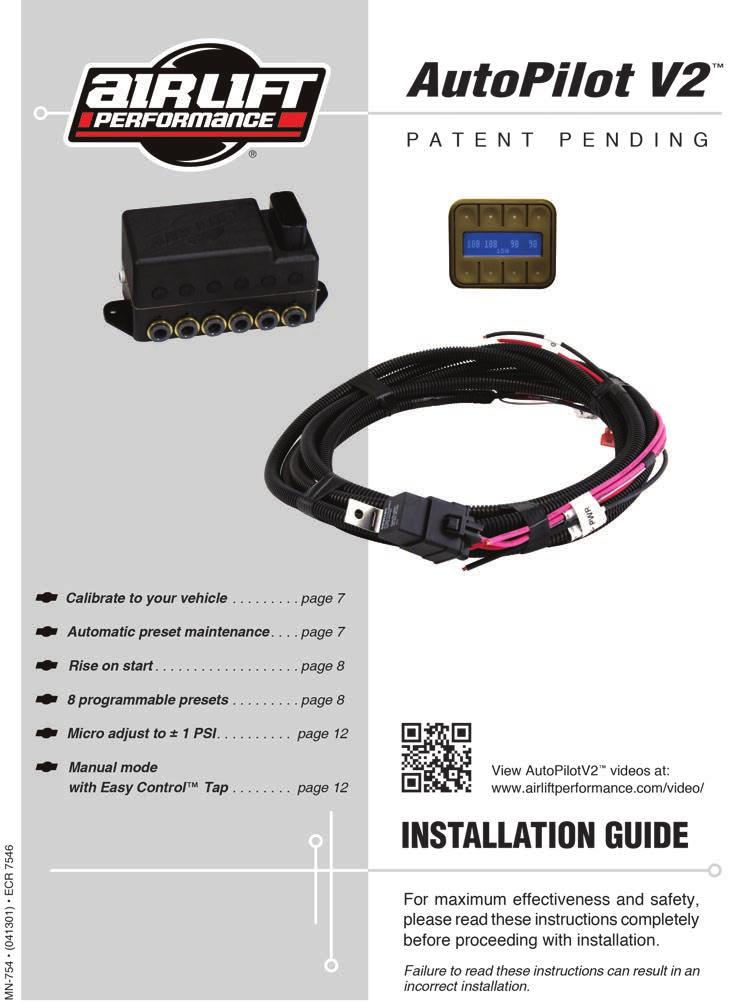
1 Kit Details HARDWARE LIST Part # Description Qty pt Fast Air Manifold - 1/ Gen 3 Display Electrical Harness - FastAir DOT 1/4 Air Line...2ft Fuse, spade 3amp Fuse, spade, 30amp ATC Fuse holder w/ cap GA Butt Connector GA Butt Connector GA Ring Terminal 3/ Female Spade Terminal GA Female Spade Terminal Adaptor, Mini Fuse...1 Part # Description Qty ATC/ATO Fuse Adaptor /2 MNPT X 1/4 FNPT /2 MNPT Center Sunk Hex Plug DOT Swivel Elbow 1/4Pipe - 1/4 PTC DOT Swivel Elbow 1/4MNPT-1/4PTC Push Lock Valve DOT 1/4 Air Line...50ft /4-14 X 1 Heavy Duty Washer /8 Flat Washer /8-16 x 1.25 Hex Cap Screw /8-16 Nyloc Nut Compressor (200 psi) Air Tank (5 gallon)...1 STOP! Missing or damaged parts? Call Air Lift customer service at (800) for a replacement part. MN-784
2
3
4 TABLE OF CONTENTS Installing the AutoPilot V2 Kit... 4 NPT Assembly Instructions... 6 Air Line and Fittings Helpful Hints... 6 Setup and Calibration... 7 Program Presets... 8 Troubleshooting Guide... 9 Leak Testing and Detection... 9 Use the System Electrical Schematic Warranty and Returns Policy Replacement Information Contact Information Manifold Template AutoPilot V2 Remote Control Unit Compressor Template... 19
5 Installing the AutoPilot V2 Kit Air Lift Performance INSTALL COMPONENTS (For a complete schematic please see fig. 14, pages 10-11) 1. Layout Plan component location first. Prior to mounting components, check to make sure the electrical harness connections will reach the manifold and compressor, the compressor leader hose will reach the tank, and the plumbing will route cleanly through the vehicle. NOTE: Be sure to install all components as far as possible from any heat sources. Plan and prepare harness and plumbing routing thru the vehicle. Eliminate all sharp edges that could chafe. Use grommets when passing through compartment walls. 2. Prepare and install compressor Prepare compressor intake. If inside vehicle, attach filter to port on end of compressor (Fig. 14). If compressor located outside vehicle, snorkel inlet filter to dry location inside vehicle. Center punch and drill four holes using the template on page 19. Attach using hardware supplied with compressor. VIAIR Max. Tank Pressure 380C C C C C 175 NOTE: If harness must be lengthened, use properly sized butt connectors and wire. If extending power/ground wires, use 8AWG wire minimum or contact Air Lift for more information. NOTE: Supplied harness is only capable of powering a single compressor. If installing dual compressors, a second dedicated power wire is required. Consult page 13 for proper wiring, and contact Air Lift for an optional second compressor harness (part number: 27679). Manifold Locate manifold above compressors and tank if possible to avoid compressor ingested water from gathering in manifold. NOTE: Do not mount manifold upside down. Position manifold in desired location: make sure manifold mount surface is flat. Fasten using the two self-tapping screws. If mounting surface is not flat, add washers to space the manifold up over surface irregularities. Tank pre assembly (see fig. 14) NOTE: Air compressors ingest moisture and will deposit water in the tank. Tanks must be regularly purged be sure to provide easy access to drain/fill valve (preferably outside the vehicle). The AutoPilot V2 system does not include moisture separators or water traps, and does require periodic tank moisture drain. If using an engine driven compressor, proper oil and water filtration must be added as these compressors will contaminate the air suspension system. Water traps are available and sold separately through Air Lift Performance (part numbers: 1/ , 3/ , 1/ ) Apply thread sealant as necessary. Determine tank location and orientation prior to installing fittings. In the lower most tank threaded port, install drain/fill PTC fitting. Choose a tank threaded port for the compressor fitting. Choose the highest tank threaded port for manifold airline routing. Plug the remaining tank ports with hex plugs. Tank install (see fig. 14) Use tank feet as template, drill holes for hardware assembly. Attach tank using supplied hardware. Cut appropriate length of hose from the manifold port 5, to the PTC fitting on tank. Route drain/fill air line with schrader valve (preferably outside vehicle). Mount fitting on bottom tank port. NOTE: Use a standard hose cutter (Air Lift part number 10530) or razorblade. Cut all hose ends square and as smoothly as possible. 4 MN-754
6 INSTALL HARNESS 1. Disconnect battery ground while installing system. 2. Compressor / manifold connections (see fig. 14) Attach the manifold connector, it will click into place once fully seated. Mount the compressor relay in a preferred location using a self-tapping screw. Cut off the spade and eyelet from the compressor power and ground wires. Strip ¼ of wire casing from the compressor wires. Strip ¼ of wire casing from the black and pink harness wires. NOTE: Use an appropriate terminal crimp tool to ensure a good connection. Using butt connector attach the RED compressor wire to the PINK harness wire. Using butt connector attach the BLACK compressor wire to the BLACK harness wire. Carefully apply heat (preferably with a heat gun) to seal these connections. 3. Battery / ignition connections (see fig. 14) Identify the power, ground, + ignition leg of the harness. Ground: 10AWG black wire; Power: 10AWG red wire; Ignition: 18AWG pink wire. Route power and ground leg of the harness free from any heat source to the battery. Using butt connector attach red wire to fuse holder. Attach 3/8 eyelet to the other end of the fuse holder and attach to positive battery (+) terminal. Attach 3/8 eyelet to the black wire and attach to battery ground. Route the 18AWG pink wire to a key switched IGNITION source that remains on during cranking. Examples include: ECU, fuel pump. Do not select an accessory source. If the AutoPilot V2 display shuts off while starting vehicle this is not a true ignition source. Using butt connector attach the pink ignition wire to a fuse holder. Select ignition source and attach the fused ignition wire. Use fuse adaptors as necessary. 4. Display Route display cable as desired to the preferred operating location. Attach the display cable to the main harness cable (small white 3 cavity connector). 5. Reconnect battery INSTALL AIR LINES NOTE: Use a standard hose cutter (Air Lift part number 10530) or razorblade. Cut all hose ends square and as smoothly as possible. Route and attach air lines to air springs Route air lines free from abrasive edges and heat sources. Attach manifold port FL or 1 to the front, drivers side left spring. Attach manifold port FR or 2 to the front, passengers side right spring. Attach manifold port RL or 3 to the rear, drivers side left spring. Attach manifold port RR or 4 to the rear, passengers side right spring. Attach manifold port T or 5 to the PTC fitting previously installed on the tank. Manifold port E or 6 is the exhaust port. Port E can be left open, or routed to a preferred exhaust location. NOTE: Air lines should be pushed in firmly, with a slight back and forth rotational twist check the connection by pulling on each line to verify a robust connection. NOTE: Release the air line from the fitting by releasing air, pushing on the line, depressing the ring towards the fitting, and then pulling the hose out of the fitting. MN-754 5
7 NPT Assembly Instructions 1. Inspect port and fitting to ensure both are free of contaminants and excessive burrs and nicks. 2. Apply a stripe of liquid pipe sealant around the male threads leaving the first two threads uncovered. 3. Screw finger tight into the port. 4. Wrench tighten the fitting to the correct turns past finger tight position (see table 1). CAUTION: NEVER BACK OFF AN INSTALLED PIPE FITTING TO ACHIEVE PROPER ALIGNMENT. LOOSENING INSTALLED PIPE FITTINGS WILL CORRUPT THE SEAL AND CONTRIBUTE TO LEAKAGE AND FAILURE. Torque Specifications Fitting Size Dash Size Turns Past Finger Tight Torque lb/ft 1/8 NPT /4 NPT /8 NPT /2 NPT /4 NPT NPT ¼ NPT ½ NPT NPT Table 1 Air Line and Fittings Helpful Tips Hose bend radius 3/8 hose = 1.5 hose bend radius 1/4 hose = 1 hose bend radius Hose to fitting No side loading on fitting from hose. Hose straight for 1 before bending. Hose cutting Cut hose perpendicular to hose length. Inspect hose for scratches that run lengthwise on hose prior to insertion. Use proper hose cutter, cigar cutter, or razor on flat surface. DOT/SAEJ844 air brake hose data Maximum working pressure of 175 PSI. Not to be used for frame (body) to un-sprung mass connection, use a braided leader hose for this moving connection. 6 MN-754
8 Setup and Calibration AutoPilot V2 is an advanced pressure-based air suspension control system, that uses state-of-the-art software algorithms to calibrate or map the control system to your vehicle. Once the system is calibrated, the algorithm predicts required valve open time to move the air suspension to achieve preset target pressures. AutoPilot V2 has 8 programmable presets, allowing the user to input 8 different combinations of the 4 corner air spring pressures. After installing AutoPilot V2 in your vehicle, please follow the steps below to properly setup your new system! If changes are made after installing and calibrating the system such as changes to air springs, lines, tank, compressor, or other vehicle modifications the system must be recalibrated. SYSTEM CALIBRATION AND SETTINGS 1. Key-on/power up, and compressor should come on to fill the tank. Check to make sure system is triggered by IGNITION source. While starting the engine, the system should be ON. If not, please refer back to Install Harness on page Press buttons 1 and 5 at the same time (1+5) and hold for 5-10 seconds until settings and diagnostics mode main page appears (fig. 2). 3. Press button 1 (TANK ADJUST). Set tank pressure preference by pressing MIN and MAX up/down buttons (fig. 3). Press buttons 1+5 to exit to settings and diagnostics mode. NOTE: If tank MAX settings are changed, a system re-calibration is necessary for optimal performance. Calibrate to your vehicle NOTE: System will automatically deflate to 0 PSI and inflate to 100 PSI during calibration. 4. Press button 2 to enter CALIBRATE (fig. 4). Press SYSTEM CAL (button 1), follow instructions to calibrate AutoPilot V2 system to your vehicle. Once calibration is complete, Press buttons 1+5 to exit to the settings and diagnostics mode. 5. Press button 3 to enter BACKLIGHT (fig. 5). Set display backlight to your preference by pressing the + and on R (Red), G (Green), B (Blue). Press buttons 1+5 to exit to the settings and diagnostics mode. Automatic preset maintenance 6. Press button 4 to enter PRESET MAINTAIN (fig. 6). Press button 8 to turn ON or OFF. When ON, this function actively monitors air spring pressure and will fill to maintain active preset pressure. NOTE: This function will not exhaust pressure. If air spring pressure is higher than preset target, only the operator pressing the preset button again will activate the system to exhaust air spring pressure (for safety). Press buttons 1+5 to exit. NOTE: PRESET MAINTAIN should be off for performance/ track driving or if operating in extremely hilly areas. fig. 1 fig. 2 fig. 3 fig. 4 fig. 5 fig LF RF T LR RR MIN=145 Button Definition TANK ADJUST CALIBRATE BACKLIGHT PRESET MAIN BACKLIGHT R G ADJ B PRESET MAINTAIN? ON MAX=175 CALIBRATION MENU 1 SYSTEM CAL 2. ADJUST SYSTEM MN-754 7
9 7. Press button 8 to toggle to settings page 2 (fig. 7). 8. Press button 5 to run a compressor test (fig. 8). This function will exhaust the tank to your specified MIN tank pressure, then turn ON the compressor and measure its inflate time to achieve MAX pressure. AutoPilot V2 will record this fill time, allowing the operator to compare future fill times to determine compressor performance. Press buttons 1+5 to exit. 9. Press button 6 to view the number of hours the compressor has been running. Rise on start 10. Press button 7 to enter RISE ON START (fig. 9). This function will automatically activate valves to achieve preset 1 target pressures when the vehicle is keyed-on. This function allows the operator to drive away seconds after vehicle is started. Press buttons 1+5 to exit. 11. Press button 8 to toggle between PSI and BAR pressure units and check software version. Press buttons 1+5 to exit. NOTE: BAR stands for DeciBar values. 12. Press buttons 1+5 to exit settings and diagnostics you are now ready to create presets! Program Presets NOTE: Preset 1 should always be entered as the desired ride pressure for the RISE ON START function. 1. Determine ride pressures: press buttons 1+5 to toggle display to MANUAL mode. Manually activate each corner (see MANUAL mode section page 12) to achieve desired normal driving ride pressure. (fig. 10) 8 programmable presets 2. Program preset 1: press buttons 1+5 to toggle display to PRESET mode. Press and hold button 1 to set 1. Release button and actual air spring pressures will appear (fig. 11). Fine-tune the pressures by pressing up/down buttons. Press + hold to scroll. Press buttons 1+5 to exit. NOTE: If your system is not hitting presets quickly, change the ADJ value. Enter Settings and Diagnostics mode (press Button 1+5 for more than 5 seconds), press #2 CALIBRATE, then ADJUST SYSTEM to toggle the value between 0 and 10; higher values increase system fill rates to overshoot target pressures. 3. You are now free to program the additional 7 presets to desired pressures. Typical presets can be: Low : set pressures to the lowest possible pressures for extreme low driving stance Front up : for speed bump or driveway clearance Rear up : for added load of passengers, equipment Play : for those that want to enjoy their air suspension fig. 7 fig. 8 fig. 9 fig. 1 fig. 10 fig. 11 fig Air Lift Performance COMP TEST COMP TIME RISE ON START PSI / BAR & SWV TANK PRESSURE RANGE PSI PROCEED? YES NO RISE ON START? ON LF RF EDIT PRESET 1 EDIT T PRESET 6 LR RR Button Definition 8 MN-754
10 freedom, AutoPilot V2 has a special function that EDIT recognizes side-to-side presets. When left side pressures are equal, and right side pressures are equal but >25PSI different than left, the algorithm will activate side to side fig instead of front to back. It will also equalize all air spring PRESET 7 pressures when exiting the play preset, conserving air by using the high pressure side to inflate the low pressure side. Pairing two play presets together allows side-to-side activation that consumes far less air than manual mode activation would consume (Figs. 12 & 13). Troubleshooting Guide For further technical assistance please contact our customer service department by calling (800) , Monday through Friday. For calls from outside the USA or Canada, our local number is (517) PROBLEM CAUSE SOLUTION Compressor doesn t run. Compressor runs all the time. Air spring or tank leak. Nothing happens when the vehicle is key-on ignition active. The display does not light up. Compressor runs all the time but doesn t fill the tank. Display shows UNSUCCESSFUL There is a blown fuse or relay, bad ground, or poor electrical connections. The compressor relay is defective or there is a leak. Fitting seal or air line compromised. There is a blown fuse or a poor connection. There is a blown fuse or a poor connection. Compressor inline check valve fitting has been overtorqued. Calibration may need to be adjusted or system may need to be recalibrated. Tank pressure settings changed. Vehicle load changed significantly. Air springs/air lines/tank changed. Leak Testing and Detection Leak detection Replace the fuse, check the ground wire, or check the compressor connector. Replace the relay or locate the leak and repair. Check to make sure air lines are seated in connectors. Inspect fittings with soapy water. Trim hose or re-seal fitting. Replace the fuses and check the electrical connections. Replace the fuses and check the electrical connections. Loosen fitting and check again. Replace if needed. Adjust ADJ value or recalibrate system to reduce number of iterations. Attempt recalibration. 1. Pressure change is directly proportional to temperature change in a container that is not leaking. a. For every 10 Fahrenheit decrease the pressure by 2 PSI. b. All other pressure changes are due to air exiting the system. 2. Spray soapy water on suspect fittings and hose connections. 3. Wipe down with rag to clean. 4. Soapy water recipe a. 1/5 Dawn brand dish soap to 4/5 water. b. Dawn brand dish soap will not corrode the metals (aluminum, brass, steel) it comes in contact with. DOT/SAEJ844 hoses and fittings (industry standard) 1. Allowable leak rate < 7 (per fitting) 2. Examples a. 150 PSI in a 2.5 gallon -40 for 12 hours = PSI b. 150 PSI in a 5 gallon -40 for 12 hours = PSI c. 100 PSI in a 141 in^3 (cubic inches) for 12 hours = PSI Assumption is that the spring keeps constant volume MN-754 9
11 LF RF LR RR LF RF LR RR Air Lift Performance fig Relay schematic reference Relay schematic reference Connect direct to battery Connect direct to battery Preferred Preferred Ignition Source (on while cranking) Ignition Source (on while cranking) MN-754


12 LEFT RIGHT LEFT RIGHT NOTE: MN
13 Use the System Air Lift Performance Now that your system is set up, it s time to use it. If changes are made after installing and calibrating the system such as changes to air springs, lines, tank, or compressor the system must be recalibrated. There are two modes: PRESET and MANUAL. Pressing buttons 1 and 5 together will toggle between modes. After 10 seconds of non-use, the display enters standby where the LCD dims. Any button hit will wake-up the display and allow users to activate the system. See mode operation below for more details. PRESET mode First button press will display the programmed preset. Users can quickly view each preset prior to activating to make sure they are selecting the desired preset. A 2 nd button press of the same preset will activate it. The system will iterate up to 6 times to achieve the preset target pressures by +/- 3 PSI. Display shows PLEASE WAIT as it iterates, then will flash SUCCESSFUL when achieved or UNSUCCESSFUL if not able to achieve the target pressure window (NOTE: if your system is not hitting presets quickly, change the ADJ value). Enter Settings and Diagnostics mode (press buttons 1+5 for more than 5 seconds), press button 2 (CALIBRATE), then ADJUST SYSTEM to toggle the value between 0 and 10. Higher values increase system fill rates to overshoot target pressures. Micro adjust to ±1 PSI: If more accuracy is desired, double press the same preset and the system will refine pressures closer to target fig. 15 PRESET Mode fig. 16 MANUAL Mode MANUAL mode MANUAL mode allows the user to fill or exhaust each spring. The display will show arrows above and below the pressures to indicate manual control mode. The arrow will be solid when the spring is filling/exhausting, and just an outline when not active. MANUAL mode with Easy Control Tap The system detects button press time. For a very short (<0.1sec) duration press, the system will open the valves for a defined burst, changing pressure minimally so users can fine-tune their pressures. For a longer than 0.1 sec duration press, the valves open as long as you hold the button down. If a button is held active, the fill/exhaust will time out after 10 seconds. Fill springs: buttons 1-4 Exhaust springs: buttons MN-754
14 Electrical Schematic AUTOPILOT V2 GEN 3 PRESSURE CONTROL AUTOPILOT V2 SECOND COMPRESSOR HARNESS* * Sold seperately Air Lift Part Number fig. 17 MN
15 Warranty and Returns Policy Air Lift Company warrants its performance products for one year to the original purchaser against manufacturing defects one year from the date of purchase when used on cars and trucks as specified under normal operating conditions. The warranty does not apply to products that have been improperly applied, improperly installed, or which have not been maintained in accordance with installation instructions furnished with all products. The consumer will be responsible for removing (labor charges) the defective product from the vehicle and returning it, transportation costs prepaid, to the dealer from which it was purchased or to Air Lift Company for verification. Air Lift will repair or replace, at its option, defective products or components. A minimum $10.00 shipping and handling charge will apply to all warranty claims. Before returning any defective product, you must call Air Lift at (800) in the U.S. and Canada (elsewhere, (517) ) for a Returned Materials Authorization (RMA) number. Returns to Air Lift can be sent to: Air Lift Company 2727 Snow Road Lansing, MI Product failures resulting from abnormal use or misuse are excluded from this warranty. The loss of use of the product, loss of time, inconvenience, commercial loss or consequential damages are not covered. The consumer is responsible for installation/reinstallation (labor charges) of the product. Air Lift Company reserves the right to change the design of any product without assuming any obligation to modify any product previously manufactured. This warranty gives you specific legal rights and you may also have other rights that may vary from state-to-state. Some states do not allow limitations on how long an implied warranty lasts or allow the exclusion or limitation of incidental or consequential damages. The above limitation or exclusion may not apply to you. There are no warranties, expressed or implied including any implied warranties of merchantability and fitness, which extend beyond this warranty period. There are no warranties that extend beyond the description on the face hereof. Seller disclaims the implied warranty of merchantability. Dated proof of purchase required. Replacement Information If you need replacement parts, contact the local dealer or call Air Lift customer service at (800) Most parts are immediately available and can be shipped the same day. Contact Air Lift Company customer service at (800) first if: Parts are missing from the kit. Technical assistance on installation or operation is needed. Broken or defective parts in the kit. Wrong parts in the kit. Have a warranty claim or question. Contact the retailer where the kit was purchased: If it is necessary to return or exchange the kit for any reason. If there is a problem with shipping, if shipped from the retailer. If there is a problem with the price. Contact Information If you have any questions, comments or need technical assistance contact our customer service department by calling (800) , Monday through Friday. For calls from outside the USA or Canada, our local number is (517) You may also contact customer service anytime by at techsupport@airliftperformance.com. For inquiries by mail, our address is PO Box 80167, Lansing, MI Our shipping address for returns is 2727 Snow Road, Lansing, MI You may also contact our sales team anytime by at sales@airliftperformance.com or on the web at 14 MN-754
16 Manifold Template MN
17 16 MN-754
18 AutoPilot V2 Remote Control Unit MN
19 18 MN-754
20 16380 Compressor Template HOLE PATTERN FOR BOTTOM OF COMPRESSOR MN
21 Need Help? Contact our customer service department by calling (800) , Monday through Friday. For calls from outside the USA or Canada, our local number is (517) Thank you for purchasing Air Lift Performance products! Air Lift Company 2727 Snow Road Lansing, MI or PO Box Lansing, MI Toll Free (800) Local (517) Fax (517) Printed in the USA
Kit Details Air Lift Performance HARDWARE LIST STOP!
 Kit Details 27673 HARDWARE LIST Part # Description Qty 72605 4pt Fast Air Manifold - 1/4...1 27042 Gen 3 Display...1 26498-002 Electrical Harness - FastAir...1 20946 DOT 1/4 Air Line...60ft 24672 Fuse,
Kit Details Air Lift Performance STOP! HARDWARE LIST
 Kit Details 27671 Air Lift Performance HARDWARE LIST Part # Description Qty 72605 4pt Fast Air Manifold - 1/4... 1 27042 Gen 3 Display... 1 26498-002 Electrical Harness - FastAir... 1 24672 Fuse, spade
Compressor Isolator Kit 50714
 Air Lift PERFORMANCE Compressor Isolator Kit 50714 MN-902 (011307) ERN 7261 Compressor not supplied with isolator kit. INSTALLATION GUIDE View AutoPilotV2 videos at: www.airliftperformance.com/video/ For
Kit PERFORMANCE INSTALLATION GUIDE. Manual Air Management System
 MN-726 (041404) ECR 7825 Air Lift PERFORMANCE Kit 27666 Manual Air Management System INSTALLATION GUIDE For maximum effectiveness and safety, please read these instructions completely before proceeding
92-00 Civic/ Integra/ Del Sol/ Accord/ CRX
 92-00 Civic/ 94-01 Integra/ 93-97 Del Sol/ 90-97 Accord/ 92-95 CRX Front Kit Part No. 75440 www.airliftperformance.com MN-513 (08409) NPR 4778 Please read these instructions completely before proceeding
92-00 Civic/ Integra/ Del Sol/ Accord/ CRX
 92-00 Civic/ 94-01 Integra/ 93-97 Del Sol/ 90-97 Accord/ 92-95 CRX Front Kit Part No. 75440 www.airliftperformance.com MN-513 (08409) NPR 4778 Please read these instructions completely before proceeding
Air Lift. Kit PERFORMANCE INSTALLATION GUIDE Scion xb
 Air Lift PERFORMANCE Kit 75599 2008 Scion xb MN-687 (031111) ECR 7189 INSTALLATION GUIDE For maximum effectiveness and safety, please read these instructions completely before proceeding with installation.
92-00 Civic/ Integra/ Del Sol/ Accord/ CRX
 92-00 Civic/ 94-01 Integra/ 93-97 Del Sol/ 90-97 Accord/ 92-95 CRX Front Kit Part No. 75440 www.airliftperformance.com MN-513 (08409) NPR 4778 Please read these instructions completely before proceeding
Kit INSTALLATION GUIDE. Manual Air Management System. Front Application
 Kit 27666 Manual Air Management System Front Application MN-726 (071602) ECR 8332 INSTALLATION GUIDE For maximum effectiveness and safety, please read these instructions completely before proceeding with
92-00 Civic/ Integra/ Del Sol/ Accord/ CRX
 92-00 Civic/ 94-01 Integra/ 93-97 Del Sol/ 90-97 Accord/ 92-95 CRX Front Kit Part No. 75440 www.airliftperformance.com MN-513 (08409) NPR 4778 Please read these instructions completely before proceeding
Kit INSTALLATION GUIDE. Manual Air Management System
 Kit 27666 Manual Air Management System MN-726 (091606) ECR 8450 INSTALLATION GUIDE For maximum effectiveness and safety, please read these instructions completely before proceeding with installation. Failure
WirelessAIR Advanced Integrated Remote
 Advanced Integrated Remote Kit 72000 Automatic Leveling Digital On-Board Compressor System MN-772 (011108) APQP 1313-31 INSTALLATION GUIDE For maximum effectiveness and safety, please read these instructions
Kit INSTALLATION GUIDE. 5 psi Low Pressure Sensor (Single Gauge)
") Kit 25592 5 psi Low Pressure Sensor (Single Gauge) MN-333 (141404) ECR 7953 INSTALLATION GUIDE For maximum effectiveness and safety, please read these instructions completely before proceeding with installation.
Kit 25592 5 psi Low Pressure Sensor (Single Gauge) MN-333 (141404) ECR 7953 INSTALLATION GUIDE For maximum effectiveness and safety, please read these instructions completely before proceeding with installation.
Kit INSTALLATION GUIDE. For maximum effectiveness and safety, please read these instructions completely before proceeding with installation.
 Kit 25801 MN-208 (121506) ECR 8243 INSTALLATION GUIDE For maximum effectiveness and safety, please read these instructions completely before proceeding with installation. Failure to read these instructions
INSTALLATION GUIDE. Magnetic Height Sensor. No , 25430
 Magnetic Height Sensor No. 25415, 25430 MN-601 (11610) ECR 5863 INSTALLATION GUIDE For maximum effectiveness and safety, please read these instructions completely before proceeding with installation. Failure
Kit psi Low Pressure Sensor (Dual Gauge)
") Kit 25812 5 psi Low Pressure Sensor (Dual Gauge) MN-337 (111107) ECR 7119 INSTALLATION GUIDE For maximum effectiveness and safety, please read these instructions completely before proceeding with installation.
Kit 25812 5 psi Low Pressure Sensor (Dual Gauge) MN-337 (111107) ECR 7119 INSTALLATION GUIDE For maximum effectiveness and safety, please read these instructions completely before proceeding with installation.
Kit INSTALLATION GUIDE. 5 psi Low Pressure Sensor (Single Gauge)
") Kit 25592 5 psi Low Pressure Sensor (Single Gauge) MN-333 (131107) ECR 7119 INSTALLATION GUIDE For maximum effectiveness and safety, please read these instructions completely before proceeding with installation.
Kit 25592 5 psi Low Pressure Sensor (Single Gauge) MN-333 (131107) ECR 7119 INSTALLATION GUIDE For maximum effectiveness and safety, please read these instructions completely before proceeding with installation.
Air Lift. Kit Honda Prelude ( ) PERFORMANCE INSTALLATION GUIDE
 PERFORMANCE INSTALLATION GUIDE") Air Lift PERFORMANCE Kit 75532 Honda Prelude (1992-2001) Cover illustration may not depict actual kit. MN-542 (06708) ECR 6206 INSTALLATION GUIDE For maximum effectiveness and safety, please read these
Air Lift PERFORMANCE Kit 75532 Honda Prelude (1992-2001) Cover illustration may not depict actual kit. MN-542 (06708) ECR 6206 INSTALLATION GUIDE For maximum effectiveness and safety, please read these
Kit INSTALLATION GUIDE. Single Gauge Controller
 Kit 25655 Single Gauge Controller Cover image may not depict actual kit. MN-342 (031107) ECR 7119 INSTALLATION GUIDE For maximum effectiveness and safety, please read these instructions completely before
Kit INSTALLATION GUIDE. 160 psi Air Shock Controller
 Kit 25804 160 psi Air Shock Controller Cover image may not depict actual kit. MN-203 (121107) ECR 7119 INSTALLATION GUIDE For maximum effectiveness and safety, please read these instructions completely
WirelessONE. Kit INSTALLATION GUIDE. Key Fob Activated Compressor System
 MN-751 (081407) ECR 8016 WirelessONE Kit 25870 Key Fob Activated Compressor System INSTALLATION GUIDE For maximum effectiveness and safety, please read these instructions completely before proceeding with
Introduction Important Safety Notice...2 Notation Explanation...2. Hardware List...4. Attaching the Compressor...4. Wiring the System...
 LifeSTYLE Kits 27665/27666 Cover illustration may not depict actual kit. MN-726 (02002) ECR 684 INSTALLATION GUIDE For maximum effectiveness and safety, please read these instructions completely before
Air Lift. AutoPilot V2 PERFORMANCE INSTALLATION GUIDE
 Air Lift PERFORMANCE AutoPilot V2 P A T E N T P E N D I N G MN-754 061404 ECR 7935 INSTALLATION GUIDE For maximum effectiveness and safety, please read these instructions completely before proceeding with
Air Lift. Kit PERFORMANCE INSTALLATION GUIDE Scion xb
 Air Lift PERFORMANCE Kit 75699 2008- Scion xb MN-689 (041108) ECR 7072 INSTALLATION GUIDE For maximum effectiveness and safety, please read these instructions completely before proceeding with installation.
WirelessAIR Advanced Integrated Remote
 Advanced Integrated Remote Gen 3 Kit 72000 Automatic Leveling Digital On-Board Compressor System MN-772 (051407) ECR 8016 INSTALLATION GUIDE For maximum effectiveness and safety, please read these instructions
Kit Installation Guide. Automatic Leveling Digital On-Board Compressor System
 Kit 72000 Automatic Leveling Digital On-Board Compressor System MN-681 (03806) ECR 6425 Installation Guide For maximum effectiveness and safety, please read these instructions completely before proceeding
Air Lift. Kit PERFORMANCE INSTALLATION GUIDE Scion xb
 Air Lift PERFORMANCE Kit 75599 2008 Scion xb MN-687 (031111) ECR 7189 INSTALLATION GUIDE For maximum effectiveness and safety, please read these instructions completely before proceeding with installation.
ʻ92-ʼ00 Civic/ʼ94-ʼ01 Integra/ ʻ93-ʼ97 Del Sol/ʼ90-ʼ97 Accord/ ʻ92-ʼ95 CRX
 ʻ92-ʼ00 Civic/ʼ94-ʼ01 Integra/ ʻ93-ʼ97 Del Sol/ʼ90-ʼ97 Accord/ ʻ92-ʼ95 CRX Front Kit Part No. 75440 www.airliftperformance.com MN-513 (08409) NPR 4778 Please read these instructions completely before proceeding
Air Lift. Kit PERFORMANCE INSTALLATION GUIDE. Dodge Charger, Challenger, 300C, and Magnum. (includes SRT 8 models, excludes AWD models)
") Air Lift PERFORMANCE Kit 75595 Dodge Charger, Challenger, 300C, and Magnum (includes SRT 8 models, excludes AWD models) MN-661 (031111) ECR 7189 INSTALLATION GUIDE For maximum effectiveness and safety,
Air Lift PERFORMANCE Kit 75595 Dodge Charger, Challenger, 300C, and Magnum (includes SRT 8 models, excludes AWD models) MN-661 (031111) ECR 7189 INSTALLATION GUIDE For maximum effectiveness and safety,
PERFORMANCE SUSPENSION PARTS
 PERFORMANCE SUSPENSION PARTS Introduction Air Lift Performance The purpose of this publication is to assist with the installation, maintenance and troubleshooting of this Audi A6 C5 Performance kit. It
WirelessAIR Advanced Integrated Remote
 Advanced Integrated Remote Gen 3 Kit 72000 Automatic Leveling Digital On-Board Compressor System MN-772 (021112) ECR 7233 INSTALLATION GUIDE For maximum effectiveness and safety, please read these instructions
Air Lift. Kit PERFORMANCE INSTALLATION GUIDE. Scion xa & xb
 Air Lift PERFORMANCE Kit 75572 Scion xa & xb MN-610 (091111) ECR 7189 INSTALLATION GUIDE For maximum effectiveness and safety, please read these instructions completely before proceeding with installation.
Air Lift Performance 2 MN-919
 2 MN-919 TABLE OF CONTENTS Introduction....2 Notation Explanation...2 Important Safety Notices....2 Installation Diagram...3 Hardware List...3 Installing the Air Suspension....4 Preparing the Vehicle...4
Kits 25490, Automatic Self-Leveling System
 II Kits 25490, 25491 Automatic Self-Leveling System 3 Y fuse For mini (ATM) fuse doubles (011608) ECR 8403 ORDER OF INSTALLATON height 1. Install electronic magnet sensor and bracket. r and 2. Install
Kits and Dual Gauge Analog Compressor Systems
 LoadCONTROLLER / Dual Kits 25852 and 25856 Dual Gauge Analog Compressor Systems Kit #25852 with standard duty compressor Kit #25856 with heavy duty compressor MN-746 (041202) ECR 7259 INSTALLATION GUIDE
Kit Installation Guide. Automatic Leveling Digital On-Board Compressor System
 Kit 72000 Automatic Leveling Digital On-Board Compressor System MN-681 (05902) ECR 6629 Installation Guide For maximum effectiveness and safety, please read these instructions completely before proceeding
Kit 25415, Installation GuidE. Magnetic Height Sensor
 Kit 25415, 25430 Magnetic Height Sensor MN-601 (12701) ECR 5985 Installation GuidE For maximum effectiveness and safety, please read these instructions completely before proceeding with installation. Failure
Air Lift. Kit PERFORMANCE INSTALLATION GUIDE. MKII-III Platform. front application
 Air Lift PERFORMANCE Kit 75583 MKII-III Platform front application MN-733 (021106) ECR 7094 INSTALLATION GUIDE For maximum effectiveness and safety, please read these instructions completely before proceeding
Kit INSTALLATION GUIDE. Dual Gauge Controller
 Kit 25651 Dual Gauge Controller MN-362 (171107) ECR 7119 INSTALLATION GUIDE For maximum effectiveness and safety, please read these instructions completely before proceeding with installation. Failure
Installation Guide. Single Gauge Analog Kits 25850/ LoadCONTROLLER / Single
 LoadCONTROLLER / Single Single Gauge Analog Kits 25850/25854 * Image depicts kit with standard duty compressor MN-750 (11008) APQP 1312025 Installation Guide For maximum effectiveness and safety, please
Air Lift Performance 2 MN-919
 2 MN-919 TABLE OF CONTENTS Introduction....2 Notation Explanation...2 Important Safety Notices....2 Installation Diagram...3 Hardware List...3 Installing the Air Suspension....4 Preparing the Vehicle...4
Kit INSTALLATION GUIDE. For maximum effectiveness and safety, please read these instructions completely before proceeding with installation.
 Kit 25690 MN-369 (111512) ECR 8349 INSTALLATION GUIDE For maximum effectiveness and safety, please read these instructions completely before proceeding with installation. Failure to read these instructions
Air Lift Performance 2 MN-896
 2 MN-896 TABLE OF CONTENTS Introduction....2 Notation Explanation...2 Important Safety Notices....2 Installation Diagram...3 Hardware List...3 Installing the Air Suspension.... 4 Preparing the Vehicle...4
Air Lift. Kit Dodge Charger, Challenger, 300C, and Magnum PERFORMANCE INSTALLATION GUIDE. (includes SRT 8 models, excludes AWD models)
") Air Lift PERFORMANCE Kit 75595 Dodge Charger, Challenger, 300C, and Magnum (includes SRT 8 models, excludes AWD models) MN-661 (031111) ECR 7189 INSTALLATION GUIDE For maximum effectiveness and safety,
Air Lift PERFORMANCE Kit 75595 Dodge Charger, Challenger, 300C, and Magnum (includes SRT 8 models, excludes AWD models) MN-661 (031111) ECR 7189 INSTALLATION GUIDE For maximum effectiveness and safety,
Air Lift Performance 2 MN-915
 2 MN-915 TABLE OF CONTENTS Introduction....2 Notation Explanation...2 Important Safety Notices....2 Installation Diagram...3 Hardware List...3 Installing the Air Suspension....4 Preparing the Vehicle...4
WirelessAIR. Gen 3 Kit Automatic Leveling Digital On-Board Compressor System INSTALLATION GUIDE. Advanced Integrated Remote
 Advanced Integrated Remote Gen 3 Kit 72000 Automatic Leveling Digital On-Board Compressor System MN-772 (071708) ECR 8900 INSTALLATION GUIDE For maximum effectiveness and safety, please read these instructions
No INSTALLATION GUIDE. For maximum effectiveness and safety, please read these instructions completely before proceeding with installation.
 No. 81560 MN-360 (071009) ECR 6976 INSTALLATION GUIDE For maximum effectiveness and safety, please read these instructions completely before proceeding with installation. Failure to read these instructions
Air Lift Performance 2 MN-805
 2 MN-805 TABLE OF CONTENTS Introduction.... 2 Notation Explanation....2 Important Safety Notices...2 Installation Diagram.... 3 Hardware List....3 Tools List....3 Installing the Air Suspension.... 4 Preparing
Air Lift Performance 2 MN-792
 2 MN-792 TABLE OF CONTENTS Introduction.... 2 Notation Explanation....2 Important Safety Notices...2 Installation Diagram... 3 Hardware List...3 Installing the Air Suspension.... 4 Preparing the Vehicle...4
Air Lift. Kit PERFORMANCE INSTALLATION GUIDE. Chevy Cobalt, Chevy HHR. front application
 Air Lift PERFORMANCE Kit 75594 Chevy Cobalt, Chevy HHR front application MN-644 (031111) ECR 7189 INSTALLATION GUIDE For maximum effectiveness and safety, please read these instructions completely before
Kit INSTALLATION GUIDE. Front Application. Scion xa & xb
 Kit 75572 Scion xa & xb Front Application MN-610 (101710) ECR 8900 INSTALLATION GUIDE For maximum effectiveness and safety, please read these instructions completely before proceeding with installation.
WirelessAIR Advanced Integrated Remote
 Advanced Integrated Remote Gen 3 Kit 72000 Automatic Leveling Digital On-Board Compressor System MN-772 (061410) ECR 7775 INSTALLATION GUIDE For maximum effectiveness and safety, please read these instructions
Driver Side Shown P/N Figure 1
 P/N 59544 by MN-612 (05606) ECR 5714 Please read these instructions completely before proceeding with the installation. NOTE: Unbolt the lower bracket from the leaf spring if the vehicle is to be serviced
Air Lift. Kit PERFORMANCE INSTALLATION GUIDE. MK IV Platform. Slam Front Application
 Air Lift PERFORMANCE Kit 75518 MK IV Platform Slam Front Application NOTE: FOR USE ON VEHICLES WITH FRAME C-NOTCH MODIFICATIONS ONLY. FRONT SWAY BAR MUST BE REMOVED. MN-756 (031409) ECR 8044 INSTALLATION
Air Lift. Kit Ford Mustang (S-197) Track Pack Front Application PERFORMANCE INSTALLATION GUIDE
 Track Pack Front Application PERFORMANCE INSTALLATION GUIDE") Air Lift PERFORMANCE Kit 75523 Ford Mustang (S-197) Track Pack Front Application MN-813 (021402) ECR 7920 INSTALLATION GUIDE For maximum effectiveness and safety, please read these instructions completely
Air Lift PERFORMANCE Kit 75523 Ford Mustang (S-197) Track Pack Front Application MN-813 (021402) ECR 7920 INSTALLATION GUIDE For maximum effectiveness and safety, please read these instructions completely
Air Lift. Kit PERFORMANCE INSTALLATION GUIDE. Nissan Z33 350z & Infiniti G35. Front Application (except AWD)
") Air Lift PERFORMANCE Kit 75520 Nissan Z33 350z & Infiniti G35 Front Application (except AWD) MN-792 (031403) ECR 7931 INSTALLATION GUIDE For maximum effectiveness and safety, please read these instructions
Air Lift PERFORMANCE Kit 75520 Nissan Z33 350z & Infiniti G35 Front Application (except AWD) MN-792 (031403) ECR 7931 INSTALLATION GUIDE For maximum effectiveness and safety, please read these instructions
WirelessONE. Kit Key Fob-Activated Compressor System INSTALLATION GUIDE
 Kit 25870 Key Fob-Activated Compressor System MN-751 (101710) ECR 8900 INSTALLATION GUIDE For maximum effectiveness and safety, please read these instructions completely before proceeding with installation.
Kit INSTALLATION GUIDE. 5 PSI Low Pressure Sensor (Single Gauge)
") Kit 25592 5 PSI Low Pressure Sensor (Single Gauge) MN-333 (141404) ECR 7953 INSTALLATION GUIDE For maximum effectiveness and safety, please read these instructions completely before proceeding with installation.
Kit 25592 5 PSI Low Pressure Sensor (Single Gauge) MN-333 (141404) ECR 7953 INSTALLATION GUIDE For maximum effectiveness and safety, please read these instructions completely before proceeding with installation.
Air Lift. Kits & PERFORMANCE INSTALLATION GUIDE. BMW E30 and E36/5/7/8 Compact. Rear Application
 Air Lift PERFORMANCE Kits 75673 & 78615 BMW E30 and E36/5/7/8 Compact Rear Application MN-889 (011406) ERN 7645 IMPORTANT: KIT 78615 DOES NOT COME WITH REAR SHOCKS. INSTALLATION GUIDE For maximum effectiveness
AIR CONTROL ACCESSORY KIT
 RAPID RESPONSE SYSTEM 2283 AIR CONTROL ACCESSORY KIT INSTALLATION INSTRUCTIONS Congratulations on your purchase of a new Air Control Accessory Kit. This kit was designed to provide inflation control of
Kit PSI Air Shock Controller
 Kit 25804 160 PSI Air Shock Controller MN-203 (141606) ECR 8612 INSTALLATION GUIDE For maximum effectiveness and safety, please read these instructions completely before proceeding with installation. Failure
Air Lift Performance 2 MN-886
 2 MN-886 TABLE OF CONTENTS Introduction....2 Notation Explanation...2 Important Safety Notices....2 Installation Diagram...3 Hardware List...3 Installing the Air Suspension....4 Preparing the Vehicle...4
Please read these instructions completely before proceeding with the installation. Piston
 P/N 59562 by MN-640 (01506) ECN 5208 Please read these instructions completely before proceeding with the installation. 3/8" Self Tapping Frame Bolts IMPORTANT: Nylon nut must be threaded on the thread
Kits and Single Gauge Analog Compressor Systems
 Kits 25850 and 25854 Single Gauge Analog Compressor Systems MN-750 (081504) ECR 8138 INSTALLATION GUIDE For maximum effectiveness and safety, please read these instructions completely before proceeding
Air Lift Performance 2 MN-925
 2 MN-925 TABLE OF CONTENTS Introduction....2 Notation Explanation...2 Important Safety Notices....2 Installation Diagram...3 Hardware List...3 Installing the Air Suspension....4 Preparing the Vehicle...4
Air Lift. Kit PERFORMANCE INSTALLATION GUIDE. Scion tc. front application
 Air Lift PERFORMANCE Kit 75587 Scion tc front application MN-716 (031111) ECR 7189 INSTALLATION GUIDE For maximum effectiveness and safety, please read these instructions completely before proceeding with
Air Lift. Kit MINI Cooper R50/52/53 PERFORMANCE INSTALLATION GUIDE. Rear Application CAUTION
 Air Lift PERFORMANCE Kit 78604 MINI Cooper R50/52/53 Rear Application CAUTION SEE PAGE 12 BEFORE BEGINNNING INSTALLATION (011505) ERN 7699 INSTALLATION GUIDE For maximum effectiveness and safety, please
Air Lift. Kit MK IV Platform Slam front application PERFORMANCE INSTALLATION GUIDE
 Air Lift PERFORMANCE Kit 75518 MK IV Platform Slam front application NOTE: FOR USE ON VEHICLES WITH FRAME C-NOTCH MODIFICATIONS ONLY. FRONT SWAY BAR MUST BE REMOVED. (021111) ECR 7189 INSTALLATION GUIDE
Air Lift. Kit PERFORMANCE INSTALLATION GUIDE. Scion tc. front application
 Air Lift PERFORMANCE Kit 75587 Scion tc front application MN-716 (031111) ECR 7189 INSTALLATION GUIDE For maximum effectiveness and safety, please read these instructions completely before proceeding with
Air Lift. Kit BMW E30 (excludes AWD and M3) Front Application PERFORMANCE INSTALLATION GUIDE
 Front Application PERFORMANCE INSTALLATION GUIDE") Air Lift PERFORMANCE Kit 75573 BMW E30 (excludes AWD and M3) Front Application MN-888 (011406) ERN 7645 INSTALLATION GUIDE For maximum effectiveness and safety, please read these instructions completely
Air Lift PERFORMANCE Kit 75573 BMW E30 (excludes AWD and M3) Front Application MN-888 (011406) ERN 7645 INSTALLATION GUIDE For maximum effectiveness and safety, please read these instructions completely
WirelessONE. Kit INSTALLATION GUIDE. Key Fob Activated Compressor System
 Kit 25870 Key Fob Activated Compressor System MN-751 (041202) ECR 7260 INSTALLATION GUIDE For maximum effectiveness and safety, please read these instructions completely before proceeding with installation.
INSTALLATION INSTRUCTIONS P/N 59507
 MN-251 (15906) ECN2723 INSTALLATION INSTRUCTIONS P/N 59507 Figure 1 represents a TYPICAL installation. Your vehicle may look slightly different due to make, model or year. Driver Side Only (Left Hand Drive
WirelessONE. Kit INSTALLATION GUIDE. Key Fob-Activated Compressor System
 Kit 25870 Key Fob-Activated Compressor System MN-751 (091606) ECR 8581 INSTALLATION GUIDE For maximum effectiveness and safety, please read these instructions completely before proceeding with installation.
KIT # Figure 1. Figure 2. Figure 3
 KIT #60748 BY MN-330 (02809) ECR6529 1. Jack up rear of vehicle or raise on hoist. Support frame with safety stands. Remove lower shock absorber attaching bolts. CUT BOTTOM (2) SECTIONS OFF RUBBER BUMP
Air Lift Performance 2 MN-903
 2 MN-903 TABLE OF CONTENTS Introduction....2 Notation Explanation... 2 Important Safety Notices.... 2 Installation Diagram...3 Hardware List... 3 Installing the Air Suspension....4 Preparing the Vehicle...
Kits and Single Gauge Analog Compressor Systems
 Kits 25850 and 25854 Single Gauge Analog Compressor Systems Kit #25850 with standard duty compressor Kit #25854 with heavy duty compressor MN-750 (061202) ECR 7259 INSTALLATION GUIDE For maximum effectiveness
ARC4000e 4 wheel compressor system w / 4 way Ride Pro controller
 350 S. St. Charles St. Jasper, In. 47546 Ph. 812.482.2932 Fax 812.634.6632 on the internet: www.ridetech.com ARC4000e 4 wheel compressor system w / 4 way Ride Pro controller 1 ARC5001 Compressor 1 CON6000
FIGURE 2 FIGURE 3 AFTER BEFORE
 OUTBOARD Stud Location OUTBOARD Left hand bracket shown - Right hand side opposite Bolt Location Left Hand Side Air Port Left Hand Side UPPER BRACKET ASSEMBLY (Top View) FIGURE 2 FRONT NORMAL RIDE HEIGHT:
Kit INSTALLATION GUIDE. Mitsubishi EVO X Rear Application CAUTION
 Kit 78630 Mitsubishi EVO X Rear Application CAUTION READ PAGE 11 BEFORE INSTALLATION (021602) ECR 8402 INSTALLATION GUIDE For maximum effectiveness and safety, please read these instructions completely
P/N Retaining Collar. U-BOLT Lower Pedestal REARWARD OUTBOARD
 P/N 59202 MN-406 (01903) NPR2670 1/2" Flat Nut Lock Washer 1/2" Flat Washer Straight Fitting 3/8"x7/8" Hex Head Bolt 3/8" Lock Washer Bell Tech Frame Section Upper Bracket 1/2"-13 x 1.5 " Carriage Bolt
MODEL NUMBER: MEDIUM DUTY ONBOARD AIR SYSTEM
 MODEL NUMBER: 10003 MEDIUM DUTY ONBOARD AIR SYSTEM IMPORTANT: It is essential that you and any other operator of this product read and understand the contents of this manual before installing and using
Air Lift. Kit Honda Civic (8th GEN) PERFORMANCE INSTALLATION GUIDE. Front Application
 PERFORMANCE INSTALLATION GUIDE. Front Application") Air Lift PERFORMANCE Kit 78524 Honda Civic (8th GEN) Front Application MN-950 (011503) ERN 8128 INSTALLATION GUIDE For maximum effectiveness and safety, please read these instructions completely before
Air Lift PERFORMANCE Kit 78524 Honda Civic (8th GEN) Front Application MN-950 (011503) ERN 8128 INSTALLATION GUIDE For maximum effectiveness and safety, please read these instructions completely before
Air Lift. Kit PERFORMANCE INSTALLATION GUIDE. Audi A6 C5 Platform. Front Application
 Air Lift PERFORMANCE Kit 75528 Audi A6 C5 Platform Front Application MN-915 (011311) ERN 7602 INSTALLATION GUIDE For maximum effectiveness and safety, please read these instructions completely before proceeding
Air Lift Performance 2 MN-916
 2 MN-916 TABLE OF CONTENTS Introduction....2 Notation Explanation...2 Important Safety Notices....2 Installation Diagram...3 Hardware List...3 Installing the Air Suspension....4 Preparing the Vehicle...4
Xtreme Air Command. Step 1 Prepare the components. Step 2 Select a mounting location. Parts list
 2549 60 90 400 600 30 200 120 800 psi 1000 kpa PSI 0 150 Xtreme Air Command Installation instructions Congratulations on your purchase of a new Xtreme Air Command kit. This kit was designed to provide
Light Duty Electronic Air Command
 2491 PSI BAR Light Duty Electronic Air Command INSTALLATION INSTRUCTIONS Congratulations on your purchase of a Light Duty Electronic Air Command kit. This kit was designed to provide inflation control
Air Lift Performance 2 MN-904
 2 MN-904 TABLE OF CONTENTS Introduction....2 Notation Explanation... 2 Important Safety Notices.... 2 Installation Diagram...3 Hardware List... 3 Installing the Air Suspension....4 Preparing the Vehicle...
Air Lift. Kit Honda Accord (8th GEN) Acura TL & TSX PERFORMANCE INSTALLATION GUIDE. Front Application CAUTION
 Acura TL & TSX PERFORMANCE INSTALLATION GUIDE. Front Application CAUTION") Air Lift PERFORMANCE Kit 78520 Honda Accord (8th GEN) Acura TL & TSX Front Application CAUTION READ PAGE 8 BEFORE INSTALLATION MN-935 (021503) ECR 8209 INSTALLATION GUIDE For maximum effectiveness and
Air Lift PERFORMANCE Kit 78520 Honda Accord (8th GEN) Acura TL & TSX Front Application CAUTION READ PAGE 8 BEFORE INSTALLATION MN-935 (021503) ECR 8209 INSTALLATION GUIDE For maximum effectiveness and
P/N Figure 1. Figure 2. 3 Valve Stem
 P/N 80523 BY MN-75 (12612) ECN1965 3 Valve Stem 2 1 Figure 1 1 1. Jack up front end of vehicle and place safety stands under axle. Remove front wheels and lower shock absorber attaching bolts. 2. Remove
Air Lift PERFORMANCE INSTALLATION GUIDE. Front Application for Subaru Impreza, WRX & STi. ( ): Kits & 75552
: Kits & 75552") Air Lift PERFORMANCE (2002-2007): Kits 75551 & 75552 (2008-2012): Kits 75554, 75556 Front Application for Subaru Impreza, WRX & STi MN-790 (021311) ERN 7445 INSTALLATION GUIDE For maximum effectiveness
Air Lift PERFORMANCE (2002-2007): Kits 75551 & 75552 (2008-2012): Kits 75554, 75556 Front Application for Subaru Impreza, WRX & STi MN-790 (021311) ERN 7445 INSTALLATION GUIDE For maximum effectiveness
Kit INSTALLATION GUIDE. Dodge 1500 Pickup 2 & 4WD. rear application
 Kit 52205 Dodge 1500 Pickup 2 & 4WD rear application MN-738 (011004) ERN 6877 INSTALLATION GUIDE For maximum effectiveness and safety, please read these instructions completely before proceeding with installation.
Please read these instructions completely before proceeding with the installation. Hardware Identification. (1) Barbed Tee. (6) Air Line Clamp
 Barbed Tee. (6) Air Line Clamp") by MN-446 (01007) ECN3102 Kit No. 60788 Please read these instructions completely before proceeding with the installation. Hardware Identification (1) Barbed Tee (4) Hex Nut (2) 5/16" Flat Washer (6) Air
by MN-446 (01007) ECN3102 Kit No. 60788 Please read these instructions completely before proceeding with the installation. Hardware Identification (1) Barbed Tee (4) Hex Nut (2) 5/16" Flat Washer (6) Air
Air Lift. Kit BMW E30 (excludes AWD and M3) Front Application PERFORMANCE INSTALLATION GUIDE
 Front Application PERFORMANCE INSTALLATION GUIDE") Air Lift PERFORMANCE Kit 75573 BMW E30 (excludes AWD and M3) Front Application MN-888 (011406) ERN 7645 INSTALLATION GUIDE For maximum effectiveness and safety, please read these instructions completely
Air Lift PERFORMANCE Kit 75573 BMW E30 (excludes AWD and M3) Front Application MN-888 (011406) ERN 7645 INSTALLATION GUIDE For maximum effectiveness and safety, please read these instructions completely
Air Lift Performance 2 MN-818
 2 MN-818 TABLE OF CONTENTS Introduction.... 2 Notation Explanation...2 Important Safety Notices....2 Installation Diagram... 3 Hardware List...3 Installing the Air Suspension.... 4 Preparing the Vehicle...4
I. Preparing the Vehicle
 Multiple Applications See special notes for your particular vehicle. I. Preparing the Vehicle by MN-169 (11809) ECR 6529 NOTE For Toyota Sequoias: Before proceeding with the installation, measure up 6.75
Air Lift Performance 2 MN-818
 2 MN-818 TABLE OF CONTENTS Introduction.... 2 Notation Explanation...2 Important Safety Notices....2 Installation Diagram.... 3 Hardware List....3 Installing the Air Suspension.... 4 Preparing the Vehicle....4
Air Lift. Kit PERFORMANCE INSTALLATION GUIDE. MK IV Platform. Slam Front Application
 Air Lift PERFORMANCE Kit 75518 MK IV Platform Slam Front Application NOTE: FOR USE ON VEHICLES WITH FRAME C-NOTCH MODIFICATIONS ONLY. FRONT SWAY BAR MUST BE REMOVED. MN-756 (031409) ECR 8044 INSTALLATION
Air Lift. Kit Volkswagen MKV & MKVI PERFORMANCE INSTALLATION GUIDE. Independent Rear Application
 Air Lift PERFORMANCE Kit 75690 Volkswagen MKV & MKVI Independent Rear Application MN-809 (031303) ECR 7578 INSTALLATION GUIDE For maximum effectiveness and safety, please read these instructions completely
Marketing/Design Request Approval
 Marketing/Design Request Approval 1. Project 2. Requested by Date 3. Creator Date 4. To be reviewed by Proof First revision Second revision Final 5. President Engineering designee *If dollar value is more
Air Lift. Kit Volkswagen MKVII PERFORMANCE INSTALLATION GUIDE. Front Application
 Air Lift PERFORMANCE Kit 78522 Volkswagen MKVII Front Application (for vehicles with 55mm lower strut diameter) (011411) ERN 8035 INSTALLATION GUIDE For maximum effectiveness and safety, please read these