17 KV 45MA Solid State Jacobs Ladder Kit Instructions
|
|
|
- Nelson Knight
- 6 years ago
- Views:
Transcription

1 17 KV 45MA Solid State Jacobs Ladder Kit Instructions by Physics Playground

2 WARNING: Jacobs Ladders are high voltage devices that may be lethal if touched and produce very high levels of ozone and nitrogen oxides which are both toxic gases. These kits are built and operated at your own risk and should only be assembled and used by those who are familiar with constructing and operating high voltage equipment. Once again, use at your own risk. Jacob s Ladder Introduction: Thanks you and welcome to what might be your first Jacobs Ladder and from my experience, this package contains the best combination for building a compact high output Jacobs Ladder by utilizing solid state electronics along with a very simplistic flow design that will insure consistent convection currents plus reduce the buildup of ozone and nitrogen oxides that commonly taint the arcing rod tube. The operation of a Jacob s ladder is rather simplistic in its nature such that it takes two conductive rods and runs a high voltage across them to achieve an arc at the location of the least electrical resistance, which is at the bottom where the rods are the closest. The rising of the arcs is created by the high temperature arcs that induce a hot rising convection current, causing the arc to rise along with it. For the ladder to work efficiently, the arc must be strong enough to produce significantly hot frederickgraff 2012 Page 2
3 convection currents. While most ladders operate at 10KV, this unit will run at 17 kv and pushes 30% more current then the traditional NST driven systems. You will find this combination to produce very bright fast rising arcs, however at the same time the high power output will also produce very high levels of ozone and nitrogen oxides which cause an orange tint build within the tube plus are highly toxic materials, so always use these in well ventilated areas under constant supervisions or at best, only use the ladder outdoors. To prevent the buildup of these toxic gases within the tube, you will see that a fan has been designed into the system that blows air through a 1/8 hole directly below the bottom of the arcing rods. This hole ultimately serves two purposes, the first being to flush out the toxic gases and secondly it will aid to the rising convection currents, meaning that the arcs will never get stuck. With these concepts in mind, let s get ready to build the Jacobs Ladder. To complete this ladder, you will need the tools and materials listed below and the overall build process should only take about 1 hour to complete at a moderate pace. Take your time and carefully read through the instructions. Should there be any questions along the way please do not hesitate to contact me, Frederick Graff the owner of Physics Playground at frederickgraff@hotmail.com or (209) Tool and Supplies Needed Screw Driver (standard and Phillips) Flat Jaw Pliers Small Vice Press Box Knife Electrical Tape Drill with 1/8 and 3/16 bit frederickgraff 2012 Page 3
 Screw in the two 10-24 x 4 inch machine screws through the center locations. 3) Attach the rubber feet at each location.")
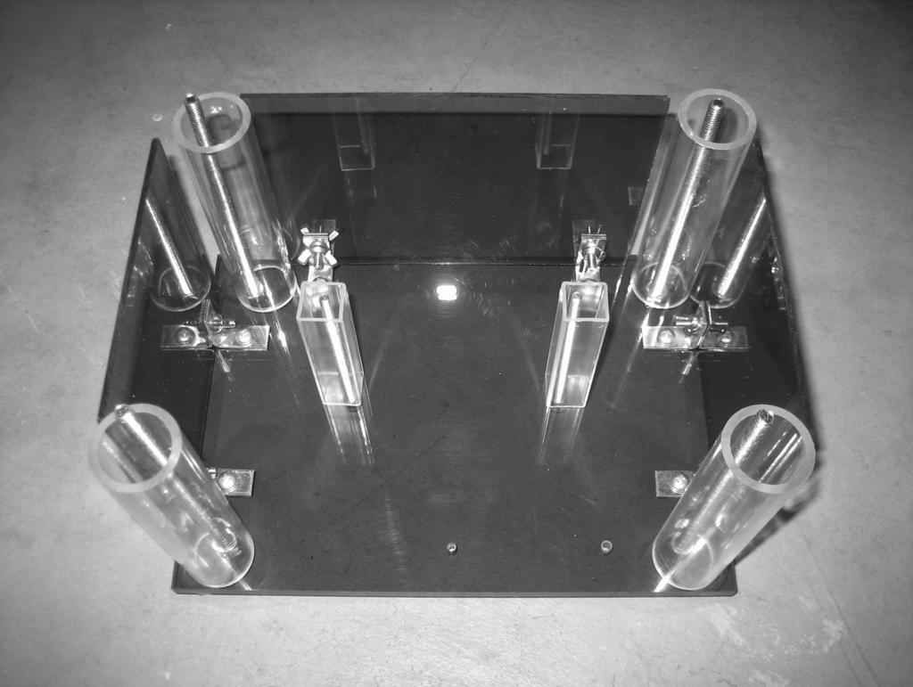
4 Base Construction Procedure: 1) Place the four large ¼-20 x 6 inch bolts through the corner locations and then fasten them with the ¼-20 bolts. 2) Screw in the two x 4 inch machine screws through the center locations. 3) Attach the rubber feet at each location. These will have a self adhesive on the bottom.
 Connect the acrylic sides at the L-Bracket location using the 10-24 x 5/8 machine screws along with the 10-24 wing nuts.")
5 4) Connect the 6 L-Brackets the side locations and fasten the with the smaller x 3/8 machine screws. 5) Connect the acrylic sides at the L-Bracket location using the x 5/8 machine screws along with the wing nuts. 6) Place in the appropriate acrylic tubes at the following locations as seen in the next illustration. 7) Attach the transformer mounting bracket and connect it with the wing nuts. 8) Attach the transformer with the smaller screws that will be located with the rod braces in a smaller bag. These screws look like small wood screws. Because the transformer is very light, only slightly snug the screws that hold the transformer to the aluminum mount.
6
 Connect one of the wires from the transformer to one of the wires from the fan and crimp both of them together on the same side using the blue wire connector.")
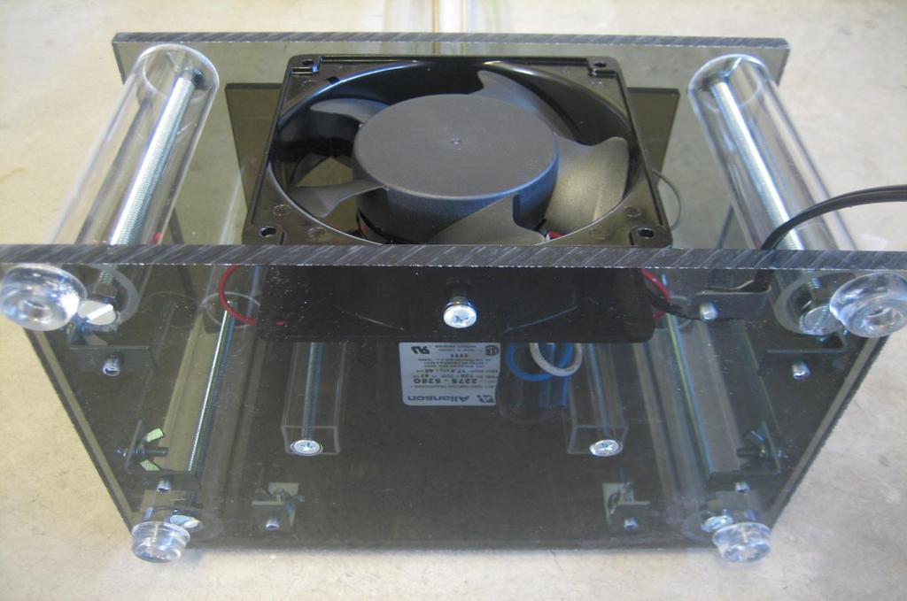
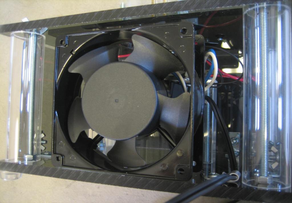
7 Wiring the circuit: 1) The fan and the transformer are wired in parallel with each other and will turn on simultaneously. 2) Connect one of the wires from the transformer to one of the wires from the fan and crimp both of them together on the same side using the blue wire connector. Do the same with the wires with another blue crimp terminal. Next, connect the other end of the crimp terminals to the power cord. Make sure that there is no wire exposed in the design.
8 Jacob s Ladder Schematic Diagram

9 3) Fasten the fan using the x ½ machine screw by inserting it from the bottom of the base. Only snug the screw. You may need to use a few small washers so that the screw does not interfere with the fan blade. 4) Next, attach the small aluminum wire brace to hold the power cord and situate the wires so that they are not touching the transformer aluminum support brace and nor motor fan. Four black zip ties have been included. If needed, use one of these to brace the wires, just know that they must be kept distant from the output wires from the transformer and its support because they will short out.
10
 Fasten on the 1 inch L-brackets using the 10-24 x 3/8 machine screws along with a few washers to space the screws. Next, attach the arcing rod support braces with two different machine screws.")
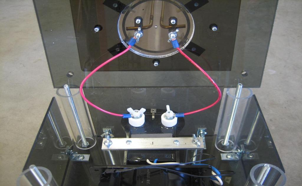
11 Arcing Rods and Tubing: 1) Connect the bottom of the tubing base to the top plate of the Jacob s Ladder Base. The acrylic will be fastened by using x 5/8 machine screws. 2) Fasten on the 1 inch L-brackets using the x 3/8 machine screws along with a few washers to space the screws. Next, attach the arcing rod support braces with two different machine screws. The side closest to the transformer output leads needs the larger x 1 inch machine screws because these will be the screws the high voltage wires connect to.
12 3) Prepare the 36 x 3/16 brass arching rods by bending them both at ¾ at each end using a vice press. 4) Using flat jaw priers, curl the other end of each rod. This does take a bit of effort. 5) VERY IMPORTANT!!! Fasten each of the rods at the base so that the rods are a 3/8 of an inch apart and no more. If the bottom gap is too far apart it will initially overload the transformer and possibly destroy the circuit of the transformer. 6) Manually adjust the angle of the rods so that they gradually draw apart toward the top. It is better that the rods slightly bow out than in. 7) Attach the bottom of the tube to the L-brackets with the nylon screws. 8) At each end of the red wires, connect the blue ring connectors. Attach one end to the transformer using the nylon screws and the other end with the metal wing nuts. Make sure that these wires bow away from each other when connected so that they cannot touch. Also, make sure that the wires do not touch the aluminum transformer brace.
13
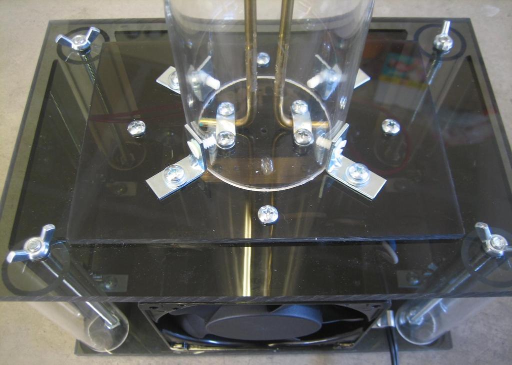
14 9) Screw on the top plate with the larger wing nuts and prepare for an initial test. WARNING: While testing, never make modifications while the system is plugged in!!! Check that the main power lines are not touching the aluminum transformer support system or fan blades. Use black zip ties or electrical tape if needed to separate and protect wires. Check that the high voltage red wires are not touching each other or the aluminum support system. Make sure all screws are fastened. Check that the top of the rods are far apart however not yet fastened because you may need to make adjustments. Check that the bottoms of the rods are not more that 1/4 to 3/8 of an inch apart. 10) The entire system should be thoroughly connected. With your left hand behind your back for safety and you are not touching any part of the ladder except the power supply, turn on the system for no more that 45 seconds. The fan should start up and the arc should start to run up the column. 11) Unplug the system before you take the next steps!!! 12) Trouble shooting: (Must have power off while trouble shooting) If the arc is stuck at the bottom slightly widen the bottom of the rods. If the rods are bowed inward the arc may not climb to the top.
 First drill using a 1/8 drill bit and then use a large 3/16 bit.")
15 13) Once the system is running properly, you will need to find the top hole locations to run the black zip ties through to secure the top of the brass rods. Eye the locations and then place a mark to drill the holes through the acrylic. 14) First drill using a 1/8 drill bit and then use a large 3/16 bit. Run the drill bits in reverse otherwise the acrylic will crack unless you have special acrylic drill bits. 15) Connect the top black end cap to the tubing and use a box knife to cut out a small 1/n hole to allow the gases to escape.
16 Jacobs Ladder Operation and Safety: 1) Only use the Jacob s Ladder in well ventilated areas. 2) Never leave unattended. 3) Never touch the ladder while in operation and always keep it in safe location away from reach. 4) Never stick body parts or foreign object in the unit while running 5) Do not operate if under the influence of medication or drugs. 6) The transformers are designed to have a constant duty cycle so there are no time limits on the run time. WARNING: Use at your own risk.
17 Solid State Jacob s Ladder Part Check List: Instructions are accessed from the website under Jacob s Ladder Kit Instructions Base and Structure Components: 1) Top and Bottom Acrylic 2) 3 side panels 3) Tubing Base 4) Acrylic Tube 5) 4 Rubber Feet 6) (2) Acrylic Transformer Supports 7) Aluminum Transformer Support Electrical 1) 17.5 KV Solid State Transformer 2) 120 x 120 x 38 AC Cooling Fan Tapped ) Extension Cord 4) 2 Wire Braces 5) 2 Wire Connectors 6) 4 Ring Terminal Connectors 7) Aluminum Wire Brace 8) 3/16 x 36 Brass Electrodes 9) 5 Black Zip Ties 10) Tubing Cover 11) Two Sections of 16 Gauge Wire 12) Danger HV Sticker 13) (2) Brass Electrode Brace Hardware: 1) (4) 1/4 x 20 x 6 Bolts 2) (4) 1/4x20 Bolts 3) (4) 1/4 x 20 W-nuts 4) (10) L-Brackets 5) (2) x 4 Bolts 7) (12) x 5/8 Screws 8) (10) W-nuts 9) (2) x 1 Screws 10) (2) Nylon Wing Nut 11) (2) Transformer Screws 6) (11) x 3/8 Screws
18
Materials List: Tools List:
 Materials List: Anchor assembly Automated power supply Automated power supply hardware packet Automation bracket assembly Automation bracket assembly hardware packet Automation winch assembly Cable Cable
Important: Please read these instructions carefully and completely before starting the installation. TITAN Fuel Tanks INSTALLATION INSTRUCTIONS
 TITAN pt. no.: 99 0000 0509 Important: Please read these instructions carefully and completely before starting the installation. TITAN Fuel Tanks INSTALLATION INSTRUCTIONS I n B e d F u e l T a n k Shown
Installation Instructions
 Installation Instructions (2) 10-24 Black flathead Allen Screws Tailgate End Front Cover Passenger Side Rail (has inspected by sticker under rail) (4) 10-32 Screws (stainless) Front Cover Exploded View
5830 Skylight, Solar Smart Retrofit Installation
 Introduction The Solar Smart has a mounting bracket that allows the operator to rotate slightly to reduce wear and tear on the chain drive system for greater performance and reliability. Because of this
Volvo P1 Air Intake. ELEVATE Turbo Intake Pipe. MAF Sensor. Inlet Manifold. Air Filter Housing. ECU Cover
 Volvo P1 Air Intake Tools needed: 13mm Combination Wrench Flat Blade Screwdriver T30 Torx Driver T25 Torx Driver 8mm Combination Wrench and/or Socket with Ratchet 10mm Combination Wrench and/or Socket
MATCHLESS SPINNING WHEEL
 MATCHLESS SPINNING WHEEL Single Treadle to Double Treadle Conversion Instructions Find out more at schachtspindle.com Schacht Spindle Company 6101 Ben Place Boulder, CO 80301 p. 303.442.3212 f. 303.447.9273
Installation Instructions Table of Contents
 Installation Instructions Table of Contents Pre- Installation of Garage Storage Lift 2 Layout the Garage Storage Lift 3 Installing the strut Channels 3 Install the Drive Assembly 5 Install the Drive Shaft
INSTALLATION & OWNER S MANUAL
 INSTALLATION & OWNER S MANUAL CAB INSTALLATION INSTRUCTIONS FOR E-Z-GO MPT BALL CAGE (p/n 72685-G01) The contents of this envelope are the property of the owner. Be sure to leave with the owner when installation
Toyota Tacoma Winch Mount Bumper Installation Instructions Tools Required: Transmission cooler relocation brackets Torque Wrench
 2016-2017 Toyota Tacoma Winch Mount Bumper Installation Instructions Tools Required: Items Included: Small flat head screw driver Winch Mount Ratchet, 10mm, 12mm, 14mm, 17mm & Skid Plate 19mm sockets Transmission
WARNING NOTICE CAUTION ASSEMBLY INSTRUCTIONS
 MODEL 284 EZ-GLIDE SYSTEM 10' HIGH CUBE VAN DRIVER SIDE ALUMINUM DROP DOWN LADDER RACK ATTENTION Read and understand all instructions and warnings before operating or using this product. WARNING This product
Top Down Rollstar Shade Installation Instructions
 Top Down Rollstar Shade Installation Instructions Thank you for purchasing your new Rollstar shade. It has been custom-made from the highest quality materials to the dimensions you specified. With proper
10 AMP ON BOARD BATTERY CHARGER
 R A Valley Forge Company MODEL 2611A-1-B 10 AMP ON BOARD BATTERY CHARGER One Output OWNER S MANUAL IMPORTANT! READ THESE INSTRUCTIONS BEFORE INSTALLING AND USING THIS PRODUCT. Keep these instructions for
Wolverine Turn Signal / Horn Kit 2102
 All years Yamaha Wolverine STOP - THIS KIT IS DESIGNED SPECIFICALLY FOR ALL YEAR AND MODELS YAMAHA WOLVERINE. IF YOUR MACHINE IS NOT ONE OF THESE MODELS DO NOT PROCEED. Contact Ryco Motorsports or your
Down and Out Motor Mount Assembly & Installation Directions
 Down and Out Motor Mount Assembly & Installation Directions Mounting the Down and Out Motor Mount correctly takes a lot of thought and a lot of planning. Please read the directions thoroughly and plan
40 EP Gee Bee Y Scale ARF V2 Instruction Manual Specs:
 40 EP Gee Bee Y Scale ARF V2 Instruction Manual Specs: Wing Span: 40" Overall length: 30" Wing area: 306 sq. in Ready to fly weight: 28~32 oz Motor/Engine: Electric: Uranus-28309 brushless outrunner motor,
Convertible Top Installation Instructions
 Convertible Top Installation Instructions For: Dodge Ramcharger, Part Number: 51318 Plymouth Trailduster 74-80 Congratulations on your purchasing decision. Bestop designed the Convertible Top to give you
Installation Instructions
 Instructions Created by an: DIY Underhood LED Lighting Kit (SKU# DIY-E-UHLK) Installation Instructions NOTICE: This Under Hood Light Kit was installed on a 2002 Toyota Tacoma. However, these instructions
This harness kit includes: Installing the Hybrid ReVolt Universal grid charger in an Insight
 Installing the Hybrid ReVolt Universal grid charger in an Insight This harness kit includes: Insight harness (2000 to 2006) (a) 4 #6 mounting screws for bulkhead (c) 2 sheet metal screws for fan board
Welcome to PTI--Photon Technology International--Optical Building Blocks!
 Search: GO Power Supplies Model LPS-220 Lamp Power Supply OPERATION MANUAL CONTENTS 1. DESCRIPTION Introduction Specifications 2. INSTALLATION Arc Lamps Tungsten-Halogen Lamps 3. OPERATION Arc Lamps Tungsten-Halogen
***THE OWNER'S MANUAL MUST BE GIVEN TO THE END USE CUSTOMER AFTER COMPLETING THE INSTALLATION.***
 INSTALLATION INSTRUCTIONS FOR THE MOTOR TRIKE HARLEY MECHANICAL REVERSE 1999-2006 FIVE SPEED FLH LAST UPDATED: OCTOBER 2011 AS THE INSTALLER OF THIS MECHANICAL REVERSE, YOU MUST BECOME FAMILIAR WITH PROPER
INSTALLATION INSTRUCTIONS
 Ultrasonic Rear Park Aid Kit (Kit # 9002-3000) INSTALLATION INSTRUCTIONS Please read thoroughly before starting installation and check that kit contents are complete. Items Included in the Kit: 4 Ultrasonic
Installation Manual. For. Trident Boat Lifts
 Installation Manual For Trident Boat Lifts Page 2 Safety Precautions 1. Your boat lift is a heavy duty piece of equipment. It is important that all persons that may operate this unit have read and understood
4' x 10' Assembly Instructions. We re Here To Help! Call Toll Free Section Roll In Dock Shown
 4' x 10' Assembly Instructions TM 4 Section Roll In Dock Shown We re Here To Help! Call Toll Free 1-888-752-9782 Customer Service: Monday - Friday, 8:00 A.M. to 5:00 P.M. C.S.T. TABLE OF CONTENTS - ALUMINUM
INSTALLATION INSTRUCTIONS SEMI-HIDDEN WINCH MOUNT Part Number:70005 Application: Ford Super Duty
 INSTALLATION INSTRUCTIONS SEMI-HIDDEN WINCH MOUNT Part Number:70005 Application: Ford Super Duty Your safety, and the safety of others, is very important. To help you make informed decisions about safety,
A B C D E F. b.tools Required (supplied by others) 3/16" Drill Bit 3/8" Wrench Phillips Head Screwdriver
 3/16 Drill Bit 3/8 Wrench Phillips Head Screwdriver") Page 1 of 13 5E.1 Parts List a. Below Deck Automatic Retractable Security Cover Kit (1) Tube End Bearing Plate (A) (1) Rope Reel with Motor Attached (B) (1) Rope Reel Cover (C) (1) Cover Drum (1) Cover
Page 1 of 13 5E.1 Parts List a. Below Deck Automatic Retractable Security Cover Kit (1) Tube End Bearing Plate (A) (1) Rope Reel with Motor Attached (B) (1) Rope Reel Cover (C) (1) Cover Drum (1) Cover
JEEVES. JEEVES Installation Manual. Installation Manual The Easiest Do-It-Yourself Dumbwaiter on the Market
 1 888-323-8755 www.nwlifts.com JEEVES Installation Manual The Easiest Do-It-Yourself Dumbwaiter on the Market This manual will cover the installation procedure step-by-step. The installation of this dumbwaiter
SUT-250-S (These instructions are used for SUT-250-SCLC also)
") SUT-250-S (These instructions are used for SUT-250-SCLC also) Torque wrench, carpenters square, wire cutters, Phillips screwdriver, 7/16, 9/16, and 3/4 combination wrenches, ratchet, 9/16, 3/4, 13/16,
SUT-250-S (These instructions are used for SUT-250-SCLC also) Torque wrench, carpenters square, wire cutters, Phillips screwdriver, 7/16, 9/16, and 3/4 combination wrenches, ratchet, 9/16, 3/4, 13/16,
Additional Instructions for 6" Drop
 Serving the Truck & Trailer Industry Since 1944 Additional Instructions for 6" Drop Attention Dealers: Please give this manual to the customer when product is delivered. Call 800-535-9545 www.aeroindustries.com
STICK F Class 60 Class INSTRUCTION MANUAL. Or Electric equivalent. (2T engine) (4T engine) Radio control model SPECIFICATIONS
 (4T engine) Radio control model SPECIFICATIONS") Radio control model 45 Class 60 Class (2T engine) (4T engine) Or Electric equivalent INSTRUCTION MANUAL STICK F - 1500 SPECIFICATIONS Wingspan 60 in. Length 38.5 in. Electric Motor 650 Watt Glow Engine.45
Radio control model 45 Class 60 Class (2T engine) (4T engine) Or Electric equivalent INSTRUCTION MANUAL STICK F - 1500 SPECIFICATIONS Wingspan 60 in. Length 38.5 in. Electric Motor 650 Watt Glow Engine.45
Mustang Shaker
 2005-2009 Mustang Shaker CDC #110050 ( 05/ 06) or 0711-7000-01 ( 07/ 09) Component Check List: Quantity/Description Part # CDC Installer 1 - Engine Cover Assembly 114050 1 - Aluminum Shaker Scoop 183020
Instructions for MB832 Manual Barrier Ver0614
 Instructions for MB832 Manual Barrier Ver0614 Read all the instructions before starting It is recommended that Locktite Blue brand thread sealant be used for all arm and pivot bolts as added protection
SONOZAIRE ODOR NEUTRALIZER Service Instruction Section
 ROUTINE MAINTENANCE The Sonozaire requires routine maintenance for years of service at maximum ozone output. This occasional maintenance requires only minor cleaning and will take only a few minutes. Failing
Fabric Studio Custom Roll Shades Installation Instructions
 Fabric Studio Custom Roll Shades Installation Instructions Cassette System Battery Motor Lifting System Inside or Outside Mount Thank you for purchasing your new roll shade. It has been custom-made from
2. With the rear door open remove pull-style clip from the passenger side just below the door latch.
 LoD Offroad FJ Cruiser Rear Bumper with Tire Carrier Installation Instructions 1. Begin with removing factory spare from the rear door. 2. With the rear door open remove pull-style clip from the passenger
2016 HONDA 1000 Pioneer PN 3102 Turn signal / horn kit rev nc
 2016 Honda 1000 Pioneer STOP - THIS KIT IS DESIGNED SPECIFICALLY FOR 2016 HONDA 1000 PIONEER IF YOUR MACHINE IS NOT THIS MODEL DO NOT PROCEED. THIS KIT DOES NOT WORK ON THE PIONEER 500 nor 700 S. Contact
ALMOST READY TO FLY. Wing Span in cm. 2
 ASSEMBLY MANUAL ALMOST READY TO FLY MS:X9 Specifications Wing Span --------------------------61.4 in ---------------------------156cm. 2 Wing Area --------------------------606.1 sq.in ------------------
Section 13. Tail Rotor Drive. RotorWay International A600 TALON Construction Manual. Section 13. Page A
 RotorWay International Page A Tail Rotor Drive Procedures covered in this section: Install driveshafts and gearboxes; install drive belt and tensioner; fabricate and install tail rotor pitch actuator arms;
BMW Z4 - By: Eigenes Bild (CC-BY-SA)
") Instructions to transfer the hydro pump on a BMW Z4 (E85) to the trunk (AKA boot) and replace the hydraulic hinges and hydraulic hoses if necessary. Graciously provided by Chuck B in Illinois. BMW Z4 -
Instructions to transfer the hydro pump on a BMW Z4 (E85) to the trunk (AKA boot) and replace the hydraulic hinges and hydraulic hoses if necessary. Graciously provided by Chuck B in Illinois. BMW Z4 -
12V 1 AMP (1000 ma) Automatic Battery Charger & Maintainer
 Automatic Battery Charger & Maintainer") 12V 1 AMP (1000 ma) Automatic Battery Charger & Maintainer For lead-acid batteries THIS MANUAL CONTAINS IMPORTANT SAFETY AND OPERATING INSTRUCTIONS FOR 12V BATTERY CHARGER: YUA1201000 / INT1201000 KEEP
12V 1 AMP (1000 ma) Automatic Battery Charger & Maintainer For lead-acid batteries THIS MANUAL CONTAINS IMPORTANT SAFETY AND OPERATING INSTRUCTIONS FOR 12V BATTERY CHARGER: YUA1201000 / INT1201000 KEEP
Dear Customers. : i MiEV INSTRUMENT PANEL ILLUMINATION INSTALLATION AND HANDLING INSTRUCTIONS. Attention
 Dear Customers Thank you for purchasing a Mitsubishi genuine optional part. For proper use of the product, please read this leaflet thoroughly. It is recommended you keep this leaflet at hand for future
Trackstar Motorized Folding Shade Installation Instructions
 Trackstar Motorized Folding Shade Installation Instructions Thank you for purchasing your new Trackstar folding shade. It has been custom-made from the highest quality materials to the dimensions you specified.
Installation Manual. For. Hi-Speed Alumavator / Platinum Vertical Boat Lifts
 Installation Manual For Hi-Speed Alumavator / Platinum Vertical Boat Lifts Page 2 Safety Precautions 1. Your boat lift is a heavy duty piece of equipment. It is important that all persons that may operate
INSTALLATION INSTRUCTIONS Mitsubishi Lancer Evolution VIII / IX Fuel Surge Tank Kit Document#
 d INSTALLATION INSTRUCTIONS Mitsubishi Lancer Evolution VIII / IX Fuel Surge Tank Kit Document# 19-0077 Brie Tech Support: info@radiumauto.com CAUTION: Exercise extreme caution when working with the fuel
Important: Please read these instructions carefully and completely before starting the installation. TITAN Fuel Tanks INSTALLATION GUIDE
 TITAN pt. no.: 03 0000 0128 Important: Please read these instructions carefully and completely before starting the installation. TITAN Fuel Tanks INSTALLATION GUIDE 30 Gallon* Spare Tire Auxiliary Fuel
U L T I M A T E R A D A R / L A S E R D E F E N S E S Y S T E M
 S m a r t e r Q u i e t e r M o r e A c c u r a t e U L T I M A T E R A D A R / L A S E R D E F E N S E S Y S T E M Installation Manual PASSPORT 9500ci Comes Complete Front Radar Receiver Miniature weatherproof
Kodak 750H Carousel Projector Repair
 Kodak 750H Carousel Projector Repair An AT YOUR OWN RISK PROJECT by Klaus Wolter, Rev B, 3-26-2016 Here I documen the repair of my 750H carousel. A common problem with this projector, and all of the projectors
Turn Signal / Horn Kit PN 7101 by All years Polaris RZR 1000 and RZR 900, 900-4, 900 trail, 900S and 900XC STOP - THIS KIT IS DESIGNED
 All years Polaris RZR 1000 and 1000-4 2015 RZR 900, 900-4, 900 trail, 900S and 900XC STOP - THIS KIT IS DESIGNED SPECIFICALLY FOR ALL YEAR AND MODEL POLARIS RZR 1000 AND 1000-4. ALSO THE 2015 POLARIS RZR
INSTALLATION INSTRUCTIONS
 INSTALLATION INSTRUCTIONS Part# 69-0717 AIR IT UP 4 Tire On Board Installed Air Delivery System with Rear Mounted Controller (Requires External Air Source) For the most up-to-date instructions please visit
Installation Instructions Z-Gate Shifter
 Installation Instructions Z-Gate Shifter Part Number 80681 1998, 2001 by B&M Racing and Performance Products The B&M Z-Gate shifter can be used in vehicles equipped with most popular three speed automatic
L/6.7L DODGE CUMMINS
 6/15/2016 #1050310D 2005-09 5.9/6.7 Dodge Cummins FlowMAX Lift Pump Kit (I-00170) - 1-2005-09 5.9L/6.7L DODGE CUMMINS BD FLOWMAX LIFT PUMP KIT Installation Instructions P/N # 1050310D PLEASE READ ALL INSTRUCTIONS
INSTALLATION INSTRUCTIONS HD BUMPER AND WINCH MOUNTING KIT Part Number: 74777, Application: 08-NEWER FORD SUPER DUTY WARNING
 INSTALLATION INSTRUCTIONS HD BUMPER AND WINCH MOUNTING KIT Part Number: 74777, 76250 Application: 08-NEWER FORD SUPER DUTY Your safety, and the safety of others, is very important. To help you make informed
Prusa i3 Printer Assembly Guide
 Prusa i3 Printer Assembly Guide Special thanks to Carlos Sanchez and Miguel Sanchez for the graphics. All graphics captured from their great animation: http://www.carlos-sanchez.com/ Prusa3/ For copyright
THIS GUIDE IS INTENDED FOR DEALERS AND SOLAR COMFORT TECHNICIANS ONLY AND IS NOT MEANT OR INTENDED TO BE REPRODUCED OR DISTRIBUTED TO THE CONSUMER
 THIS GUIDE IS INTENDED FOR DEALERS AND SOLAR COMFORT TECHNICIANS ONLY AND IS NOT MEANT OR INTENDED TO BE REPRODUCED OR DISTRIBUTED TO THE CONSUMER Table of Contents Page Tools Needed (A) 3 Replacement
QTY 3D PART NO. DESCRIPTION
 QTY 3D PART NO. DESCRIPTION 1 691032 V6 FRONT AIR DAM 1 691023 SIDE SKIRT RIGHT 1 691024 SIDE SKIRT LEFT 1 691566 V6 DUAL EXHAUST REAR LOWER SKIRT- 8 3M 94 3M ADHESION PROMOTER 24 #8 X ¾ SELF DRILLING
Electrical Safety World Video Episode 1 Electricity Basics
 Episode 1 Electricity Basics 1. Which of these carries electricity from power plants to substations? a) steel pipes c) outlets b) transmission lines d) windmills 2. What does a substation do? 3. Unless
Installation Instructions Supertop NX Twill
 Installation Instructions Supertop NX Twill Vehicle Application: Jeep Wrangler Unlimited 2007-current Part Number 54823 Installation Tips Before you begin installing your new Supertop NX Twill, please
Model: PSB100. Rear Parking Sensor System. Installation Manual TABLE OF CONTENTS
 Rear Parking Sensor System Model: PSB100 Installation Manual TABLE OF CONTENTS Warnings...2 Product Description...3 Packing List...3 Installation Instructions...4 Mounting the Sensors...4 Installing the
Combine Cover Manual
 Combine Cover Manual Installation Instructions Page 27 Operating Instructions Page 8 Warranty Page 8 Trouble Shooting Page 9 11 For Model s: Case I.H. 2388, 2188, 1688 and 1680 With a MAURER Hopper Extension
Li-ion Cordless Screwdriver
 Li-ion Cordless Screwdriver HPC-0023 Please note that your safety is your personal responsibility PLEASE READ BEFORE USE AND RETAIN THESE INSTRUCTIONS FOR FUTURE REFERENCE. IMPORTANT NOTE: ALWAYS CHECK
PN PONTIAC FIREBIRD. Kit Contents: Four Panel Sequential LED Tail Light Kit Installation Guide
 1969 PONTIAC FIREBIRD Four Panel Sequential LED Tail Light Kit Installation Guide Kit Contents: 4 LED panels 4 rubber grommets 1 power wire 2 pigtail harness kits 2 crimp terminal kits PN 1100569 1969
RIM Hood For Aeromaster Bodies
 RIM Hood For Aeromaster Bodies Service Guide WARNING: Hood should be opened by releasing the hold-down straps, lifting the hood, and engaging the prop rod. Be sure prop rod is properly engaged before working
ROUTINE MAINTENANCE. Howe-Baker Engineers, Ltd. 20
 ROUTINE MAINTENANCE The Sonozaire model 105A requires only routine maintenance for years of service. This occasional maintenance requires only minor cleaning and will take only a few minutes. Failing to
SPACESAVER EC-300 A ELECTRICS
 INSTALLATION INSTRUCTIONS SPACESAVER EC-300 A ELECTRICS SECTION I TOP MOUNTED ELECTRICS SECTION II FACE PANEL MOUNTED ELECTRICS SECTION III ZFS INSTALLATION INSTRUCTIONS This symbol indicates a connection
PMC-MC-X2-Chassis PMC-MC-X4-Chassis
 DYNAMIC ENGINEERING 150 DuBois St Suite 3, Santa Cruz Ca 95060 831-457-8891 Fax 831-457-4793 http://www.dyneng.com sales@dyneng.com Est. 1988 User Manual Four Slot Carrier Two Slot Carrier PMC-MC-X2-Chassis
Portable Ladder Safety. Baboquivari Unified School District NO. 40
 Portable Ladder Safety Baboquivari Unified School District NO. 40 Agenda Importance of Ladder Safety An Approved Ladder Types of Ladders Stepladders Extension Ladders Controlling Hazards Inspecting the
Marlon Xplore II / Xplore Pro II Deck Installation & Assembly Instructions
 Marlon Xplore II / Xplore Pro II Deck Installation & Assembly Instructions Marlon Recreational Products www.marlonproducts.com 1-800-663-7367 INSTALLATION INSTRUCTIONS: 1. Remove the ramp from underneath
/ CABLE TIES & WIRE FASTENERS /
 Standard Self-locking Cable Ties information INFO Melting point: 265 C (509 F) Brittleness temperature: -112 C (-169 F) at 2% water Provide up to 50% more tensile strength and 15% larger bundle diameters
RADIO CONTROL MODEL ASSEMBLY INSTRUCTIONS. Wasp
 RADIO CONTROL MODEL ASSEMBLY INSTRUCTIONS Wasp TRAINER Almost ready-to-fly Wingspan 1520mm Fuselage length 1105mm Engine: 40-46 2T / 52-60 4T Electric Motor: 600-700W Radio: 5 channel / 4-5 servo RC Functions:
INSTALLATION MANUAL ALUMINUM & STEEL SIDE BOX
 TRUCK STORAGE SOLUTIONS SECURING YOUR REPUTATION INSTALLATION MANUAL ALUMINUM & STEEL SIDE BOX STEEL & ALUMINUM SIDE BOX WITH PACK RAT DRAWER UNITS MODELS ATTENTION: PLEASE READ AND UNDERSTAND ALL INSTRUCTIONS
GENUINE PARTS INSTALLATION INSTRUCTIONS
 GENUINE PARTS INSTALLATION INSTRUCTIONS 1. 2. 3. 4. DESCRIPTION: Accent light Kit APPLICATION: R42H (2011) PART NUMBER: 999F3 AW000 - Universal Accent Lighting Kit. KIT CONTENTS: Item QTY Description Service
ITEM QTY CHECK PART NUMBER DESCRIPTION
 PART #90542A Boost Gauge Package, SLP, 2005-2013 Corvette PACKING LIST Before installation, use this check list to make sure all necessary parts have been included. ITEM QTY CHECK PART NUMBER DESCRIPTION
Replacing the Battery in the Patriot SPS 250, SPS 300 and SPS 450
 Replacing the Battery in the Patriot SPS 250, SPS 300 and SPS 450 PAT 609 P February 1, 1993 This PAT describes how to replace the battery in Patriot SPS 250, SPS 300, and SPS 450 units. Replacing the
CLEAN POWER TM CPS Series Operator s Manual
 12 Test Equipment CLEAN POWER TM CPS Series Operator s Manual Power Supply / Maintenance Charger for 12 Volt Systems The CPS series of power supplies / maintenance chargers are the ultimate in supplying
Installation Instructions
 Installation Instructions Jeep JK 2-Door (2011 Present) Mounting Bracket and Air Line System Kit for ARB On-Board Twin Air Compressor (CKMTA12) Made in the USA Kit Contents: 1 Flat Bracket 1 Formed Bracket
Carousel Unit User Manual Replacing the Check Stand Motor
 Carousel Unit User Manual Replacing the Check Stand Motor 02/01/2017 1 Table of Contents Tools:... 3 Turn Off Power to the Unit:... 4 Remove Power Switch... 5 Remove Electric Eyes:... 6 Remove POS (Point-Of-Sale)
SIP Direct Drive Oil-Lube Air Compressors - Operating & Maintenance Instructions
 SIP Direct Drive Oil-Lube Air Compressors - Operating & Maintenance Instructions Please read and fully understand the instructions in this manual before operation. Keep this manual safe for future reference.
ITEM QTY CHECK PART NUMBER DESCRIPTION. NOTE: This package does not include any accessories for gauge installation
 PART #90540A Gauge Pod Only Package, SLP, 2005-2013 Corvette PACKING LIST Before installation, use this check list to make sure all necessary parts have been included. ITEM QTY CHECK PART NUMBER DESCRIPTION
Installing LED lights in a Hypercharger By Keith Edwards Joker s Wild! (Wildjokr)
") Installing LED lights in a Hypercharger By Keith Edwards Joker s Wild! (Wildjokr) THINGS YOU WILL NEED: A Hypercharger (duh!) LEDs (The ones I got were from Benny Bryant at Fantasies on Wheels in Sylacauga,
Installing LED lights in a Hypercharger By Keith Edwards Joker s Wild! (Wildjokr) THINGS YOU WILL NEED: A Hypercharger (duh!) LEDs (The ones I got were from Benny Bryant at Fantasies on Wheels in Sylacauga,
Cordless Driver Drill
 INSTRUCTION MANUAL Cordless Driver Drill XFD0 0360 ENGLISH (Original instructions) SPECIFICATIONS Model XFD0 Steel 3 mm (/") Capacities Wood 38 mm (-/") Wood screw 0 mm x 89 mm (3/8" X 3-/") Machine screw
UNPACK AND IDENTIFY THE FOLLOWING PARTS.
 SUT-500-S ASSEMBLY REQUIREMENTS *Torque all T-bolt nuts to 35-40 foot pounds. *Check all lights before towing. *Tire pressure not to exceed recommendation on serial tag. *Re-torque wheel nuts after first
Bottom Mount Seat Mount Installation & Wiring Instructions
 E81/E87/E90/E91/E92/F22/F30/F31/F32/F80/F82/F87 (and other cars with the same sliders) Bottom Mount Seat Mount Installation & Wiring Instructions These instructions assume a basic comfort with crimping
Aquarium DIY Kit EATX Version 4
 Aquarium DIY Kit EATX Version 4 Assembly Instructions Version 1.0 ***WARNING*** Submerging your hardware in mineral oil will void your warranty. Do this project only at your own risk. Puget Systems is
Tusk Pannier Racks. Instructions and information KLR
 1 Tusk Pannier Racks Instructions and information KLR650 2008 + Congratulations on your purchase of the Tusk Pannier Racks. These racks are made to handle extreme adventure riding, but work great for the
QSSE, QSSEX INDUSTRIAL Battery Chargers
 C O R P O R A T IO N O P E R A T I N G I N S T R U C T I O N S QSSE, QSSEX INDUSTRIAL Battery Chargers INTRODUCTION The QSE line are electronically controlled float chargers. The batteries are brought
Installation Instructions for Lingenfelter GM 2500 Suburban & Yukon XL Auxiliary Fan System (with AC clutch controlled fan output)
") Installation Instructions for Lingenfelter 2007-2013 GM 2500 Suburban & Yukon XL Auxiliary Fan System (with AC clutch controlled fan output) PN L300080607 Revision - 1.1 Lingenfelter Performance Engineering
Installation Instructions for Lingenfelter 2007-2013 GM 2500 Suburban & Yukon XL Auxiliary Fan System (with AC clutch controlled fan output) PN L300080607 Revision - 1.1 Lingenfelter Performance Engineering
30,000mWh LITHIUM-POLYMER CAR JUMP STARTER USER S MANUAL PLEASE READ THIS MANUAL CAREFULLY BEFORE OPERATION
 Lithium Battery Disposal: This product contains a lithium battery. A lithium battery should not be thrown away in the trash. Please dispose of the battery at an authorized disposal or recycle center. Check
PLP Compression Dead-end & Jumper Terminal for ACSR & ACSS Conductors
 MARCH 2017 PLP Compression Dead-end & Jumper Terminal for ACSR & ACSS Conductors Be sure to read and completely understand this procedure before applying product. Be sure to select the proper PREFORMED
Replacing the Batteries in the Fortress LI 660
 Replacing the Batteries in the Fortress LI 660 This FTS describes how to replace the batteries in Fortress LI 660 units. Batteries should be replaced by a qualified technician. If you have any questions
INSTALLATION INSTRUCTIONS WINCH MOUNTING KIT Part Number: Application: Honda Rubicon/Foreman 500
 INSTALLATION INSTRUCTIONS WINCH MOUNTING KIT Part Number: 70830 Application: Honda Rubicon/Foreman 500 Your safety, and the safety of others, is very important. To help you make informed decisions about
Smooth Roll Advantage Side Dump
 Smooth Roll Advantage Side Dump Installation, Maintenance and Safety Instructions Sioux City Tarp 5201 Harbor Drive Sioux City, IA 51111 Ph: 712-258-6939 Getting Started Important: Please read manual thoroughly
INSTALLATION INSTRUCTIONS
 INSTALLATION INSTRUCTIONS Document# 19-0038 2004+ Lotus Elise (Series 2) Rear Clamshell Removal Kit Safely support the vehicle. This is a two-person job. Allow 1 to 2 hours for initial disassembly. Have
LESTRONIC II BATTERY CHARGER MODEL 07210
 LESTRONIC II BATTERY CHARGER MODEL 07210 PLEASE SAVE THESE IMPORTANT SAFETY AND OPERATING INSTRUCTIONS For correct operation of the equipment, it is important to read and be familiar with this entire manual
INSTALLATION INSTRUCTIONS SEMI Hidden Kit Part Number: Application: Toyota Tacoma
 INSTALLATION INSTRUCTIONS SEMI Hidden Kit Part Number: 100044 Application: 2016+ Toyota Tacoma GENERAL SAFETY PRECAUTIONS Your safety, and the safety of others, is very important. To help you make informed
PRODUCT USE INFORMATION
 9RC61000 Jeep YJ Body Lift Thank you for choosing Rough Country for all your suspension needs. This body lift fits both manual and Automatic equipped vehicles!!! Refer to last page of this Instruction
Design of a Station for Pump Testing
 Design of a Station for Pump Testing The system below was developed for use in the First Year Engineering Program at Louisiana Tech University. Using water around electrical devices can be hazardous. Louisiana
Page: REV 3: Add drill and tap information to Figure 4 DRILL #3, TAP 1/4-28 BOTH ENDS.
 REVISION DESCRIPTION: 1) Page: 32-03 MEMO: Step 4 should not be bold. Fix WD-1213 callout in Figure 3. Page: 32-04 REV 3: Add drill and tap information to Figure 4 DRILL #3, TAP 1/4-28 BOTH ENDS. Add make
Handyman Motor Capacitor Meter PART NO
 Handyman Motor Capacitor Meter PART NO. 2225174 To test a motor-run capacitor in the field with no capacitance meter at hand, you had to hook up the capacitor through an extension cable to a 120V wall
DIY Synth Kit - Manual STUTTER SYNTH
 DIY Synth Kit - Manual STUTTER SYNTH Welcome to the DIY Synth - Manual This is a step-by-step guide to making your own electronic Synth. All you will need is your hands and your DIY Synth kit which includes
UNPACK AND IDENTIFY THE FOLLOWING PARTS.
 SUT-250-M2 ASSEMBLY REQUIREMENTS *Torque all T-bolt nuts to 35-40 foot pounds. *Check all lights before towing. *Tire pressure not to exceed recommendation on serial tag. *Re-torque wheel nuts after first
MODEL 6010A 6 12 VOLT BATTERY CHARGER ASSOCIATE
 MODEL 600A 6 VOLT BATTERY CHARGER ASSOCIATE IMPORTANT SAFETY INSTRUCTIONS. SAVE THESE INSTRUCTIONS. This manual contains important safety and operating instructions for the battery charger you have purchased.