DESCRIPTION. Replacement of batteries B ,2. Charging of batteries B ,4. Replacement of motor B ,6
|
|
|
- Elizabeth Sharp
- 6 years ago
- Views:
Transcription
1 04- BACKUUM BATTERY/ACRO-BATT B DESCRIPTION PLAN Replacement of batteries B , Charging of batteries B ,4 Replacement of motor B ,6 Wiring diagram B Replacement of dust chamber lid, B Replacement of frame for pre-filter B Replacement of sound suppressors B Replacement of curcuit board B Replacement of dust chamber and fixed straps B


2 B REPLACEMENT OF BATTERIES 3 4
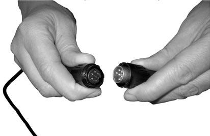
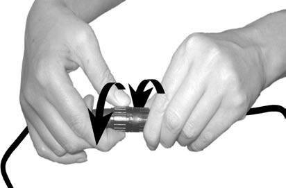
3 04- REPLACEMENT OF BATTERIES B WARNING! The charger must be disconnected from the supply mains when removing the battery. NO TOOLS NEEDED! REPLACE/CONNECT The batteries are placed inside the battery cases. NOTE! Never remove the battery from the battery case. The method of replacing batteries is to first disconnect the wires connecting the batteries to the cleaner. This is done by twisting and then pulling the clamping circuit until the wires from the cleaner are separated from the wires to the batteries. Then remove the battery case from belt. This is done by lifting up the flap and pushing the button on the backside of the battery case so that the case is separated from the belt. TEST AFTER REPLACEMENT After repair, please check that the vacuum cleaner is functioning to Nilfisk specifications and to any local authorised precautions. NOTE! NEVER REMOVE THE BATTERY FROM THE BATTERY CASE. Refit new batteries in reversed order. SCRAPPING OF BATTERIES The batteries must be removed from the appliance before the appliance is scrapped. The battery is to be disposed of safely and in accordance with all locally approved precautions and environmental regulations. Recycle packing material and all assemblies according to local regulations. DISPOSAL OF BATTERIES Return batteries to a disposal plant. If the batteries are leaking, return batteries to a disposal plant or a similar local facility. Any leakage from the batteries can be removed with household paper. Leaking batteries and fouled household paper should be placed in a sealed plastic bag and then handled according to all locally approved precautions and environmental regulations. If leakage from the batteries has been in contact with skin, eyes or clothes - remove battery leakage with water.


4 B CHARGING OF BATTERIES CHARGER LED STATUS TABLE Charge mode Red LED Green LED ON/stand-by ON ON Rapid charge ON Trickle charge Blink rapidly End of charge Blink slowly Battery over/under temp. ON Error Blink rapidly
5 04- CHARGING OF BATTERIES B BEFORE CHARGING First disconnect the wires connecting the batteries to the cleaner. This is done by twisting and then pulling the clamping circuit until the wires from the cleaner are separated from the wires to the batteries. Then remove the battery case from belt. This is done by lifting up the flap and pushing the button on the backside of the battery case so that the case is separated from the belt. Battery packs should be used and charged together as a set. Do not mix battery packs. Do not take the battery packs out of their battery case. No battery maintenance is required. The battery packs should not be altered in any way. Use and store the battery packs indoors and in a dry environment. Operating temperature is 3 F to 04 F (0 C to 40 C) and storage temperature is 5 F to F (-5 C to 50 C). Battery life will be reduced if exposed to extreme temperatures, over 40 F (over 60 C). Do not unplug the battery packs from the machine or charger by pulling on the cord. To unplug, grasp the plugs, not the cord. Do not drop the battery packs. If the battery packs appears faulty, has been dropped, damaged, left outdoors or has been exposed to water, return it to an authorized service center. Let the battery pack completely discharge every 0th cycle as a minimum, by running the machine until the machine automatically stops because of low voltage. THE CARGER The Backuum Battery / Acro-Batt is supplied with a fully automatic charger. After the battery packs have discharged from use they can be connected to the charger. The charger will automatically begin charging when the proper temperature, 3 F to 04 F (0 C to 40 C), is reached. The LEDs on the charger will blink (Green LED) rapidly when the batteries are ready for use (95% charged) and blink slowly when the batteries are completely charged (00%). When the battery packs are fully charged the charger will automatically switch into trickle charge mode and will not overcharge the batteries. Charger should be located in an area with adequate ventilation. CHARGER LED STATUS TABLE CHARGING OF BATTERIES The machine is equipped with low voltage sensor and a high temperature sensor. The machine will not operate if the battery packs are too hot or if a low voltage condition exists. Battery packs should be used and charged together as a set. Do not mix battery packs if using more than sets of battery packs. It is a good idea to mark the sets. After the battery packs have discharged from use they can be connected to the charger. The charger will automatically begin charging when the proper temperature, 3 F to 04 F (0 C to 40 C), is reached. Do not disconnect battery packs from charger while charger is running. To obtain full run time from the battery packs after charging the temperature must cool to approximately 04 F (40 C). This typically takes 0,5 hour at room temperature. If the battery packs are connected before they are cooled down, run time will be reduced due to the temperature sensor within the machine. Charge mode Red LED Green LED ON/stand-by ON ON Rapid charge ON Trickle charge Blink rapidly End of charge Blink slowly Battery over/under temp. ON Error Blink rapidly


 using the snap-lock placed")
6 B REPLACEMENT OF MOTOR Disconnect the battery packs before doing any maintenance or service on the machine. First, open the dust chamber lid. Then remove the dust chamber from motor housing, use a Torx T 0 screwdriver and loosen the 4 screws holding the filter frame in place. Remove the filter and frame. Remove the black rubber bellow from the dust chamber by folding the rubber to centre of the machine so that it turn loose from the edge of the inlet. Remove the dust chamber from motor housing. 3 Use a Torx T 0 screwdriver and loosen the 9 screws holding the distance plate and back plate attached to motor housing. 4 Lift up and remove the distance plate from motor cover. Then remove the belt from cleaner. The belt is attached to the cleaner by the lead throug and screws from distance plate to back plate. 5 6 Remove the back plate from motor housing. Release the internal motor housing (the black part) using the snap-lock placed inside the motor housing cover Unscrew the six lid screws from the internal motor housing. Unscrew the screw at the holder. Slide the holder upwards. Then loosen the rubber gasket/membrane from the inlet and slide it upwards at the wires so that you can move the wires in order to loosen the motor.

 screws.8nm Tool Type: Torx T0 screwdriver Slot driver 3.5 mm x 0.")


7 04- REPLACEMENT OF MOTOR B Disconnect the battery packs before doing any maintenance or service on the machine. Torque wrench settings: Motor housing cover () screws.8nm Frame for pre filter (4) screws.8nm Lid cover motor (6) screws.8nm Tool Type: Torx T0 screwdriver Slot driver 3.5 mm x 0.6 mm Refit parts in reversed order. Test after repair After repair, please check that the vacuum cleaner is functioning to Nilfisk-Advance specifications and to any local authorised precautions. 0 Loosen the suspension ring from the motor by lifting the suspension ring upwards from motor. Lift up the motor from motor housing. Loosen the rubber suspension from the motor by lifting the suspension rubber upwards from motor. NOTE! See the wire pulling at the old motor and at the wiring diagram before loosen the wires from the motor. WIRING DIAGRAM
8 B WIRING DIAGRAM Disconnect the battery packs before doing any maintenance or service on the machine. Sensitive to Electrostatic Discharge (ESD) CAUTION! Details sensitive to electrostatic discharge. Notice applicable ESD-safety directions (acc. to CECC0005). VARNING! Detaljer känsliga för elektrostatisk urladdning. Iakttag gällande ESD-skyddsföreskrifte (enl. CECC0005). ATTENTION! Eléments sensibles aux décharges électrostatiques. Respecter les consignes de sécurité (selon CECC0005). ACHTUNG! Teile reagieren empfindlich auf elektrostaitisches Entladen. Beachten Sie die geltenden ESD-Schutzvorschrigten (gemäß CECC0005). AVISO! Piezas sensibles a las deschargas electrostáticas. Respete las reglas de protección ESD (conforme CECC0005). VAROITUS! Sähköstaattiselle purkaukselle herkät osat. Noudata voimassa olevia ESD-turvamääräyksiä(CEC C0005).


9 04- REPLACEMENT OF THE DUST CHAMBER LID B Disconnect the battery packs before doing any maintenance or service on the machine. Tools needed: Torx T 0 Screw-driver Adjustable pliers Offset gear driven or ratcheting screwdriver. Hammer. Test after repair After repair, please check that the vacuum cleaner is functioning to Nilfisk-Advance specifications and to any local authorised precautions. Dust chamber lid Pull out dust chamber lid hinge pin with a adjustable plier. Remove and refit with the new dust chamber lid. 3 Refit dust chamber lid Fit the lid to the grooves at the chamber. Then refit the lid hinge pin back in place. Secure pin by some gentle knocks with a hammer

 with four screws (.")
10 B REPLACEMENT OF THE FRAME FOR THE MOTOR PRE FILTER Disconnect the battery packs before doing any maintenance or service on the machine. Torque wrench settings: Frame screws.8nm Tool Type: Torx T0. Offset gear driven or ratcheting screwdriver Test after repair After repair, please check that the vacuum cleaner is functioning to Nilfisk-Advance specifications and to any local authorised precautions. Open the dust lid chamber. Remove the frame () with four screws (. Replace with new frame and attach frame with the four screws. 3 Close the dust lid chamber


11 04- REPLACEMENT OF THE SOUND SUPPRESSORS B Disconnect the battery packs before doing any maintenance or service on the machine.


 Use a Torx T 0 screwdriver and loosen the 9 screws")


12 B REPLACEMENT OF THE CURCUIT BOARD Disconnect the battery packs before doing any maintenance or service on the machine. Refit parts in reversed order. Test after repair After repair, please check that the vacuum cleaner is functioning to Nilfisk-Advance specifications and to any local authorised precautions. Sensitive to Electrostatic Discharge (ESD) Use a Torx T 0 screwdriver and loosen the 9 screws holding the distance plate and back plate attached to motor housing. Lift up and remove the distance plate from motor cover. The belt is attached to the cleaner by the lead throug and screws from distance plate to back plate. Remove the belt from cleaner. 3 Remove the back plate from motor housing. Loosen the switch from curcuit board and motor housing cover. Then pull out the curcuit board from cleaner. NOTE! Before removing all wires connected to the old curcuit board, take a look at the present wire pulling and the wiring diagram below.

 removal n/a Frame screws")

 with a adjustable plier.")


13 04- REPLACEMENT OF THE DUST CHAMBER/FIXED STRAPS B Disconnect the battery packs before doing any maintenance or service on the machine. Tools needed: Torx T 0 Screw-driver Adjustable pliers Offset gear driven or ratcheting screwdriver. Hammer. Flat screw-driver Screws: Combi Torx T 0 Torque wrench settings: Chamber lid hinge pin () removal n/a Frame screws ().8Nm Refit parts in reversed order. Test after repair After repair, please check that the vacuum cleaner is functioning to Nilfisk-Advance specifications and to any local authorised precautions. Dust chamber lid Pull out dust chamber lid hinge pin() with a adjustable plier. Remove and refit with the new dust chamber lid. 3 Remove the frame () with four screws (). 4 Remove the black rubber bellow from the dust chamber by folding the rubber to centre of the machine so that it turn loose from the edge of the inlet. 5 Loosen all 4 screws holding inner and outer dust chambers together. Remove the fixed straps and the strap handle from the old dust chamber 6 Put a flat screwdriver between the inner and outer dust chamber. Gently bend the two chambers apart. Then add the ends of the strap handle and the ends of the fixed straps parts in to the space between the chambers. Put back the screws to the chambers and tighten so that the chambers are sealed and the straps are fixed between the chambers.
DRIVE SHAFT LOCATION INDEX
 DRIVE SHAFT LOCATION INDEX 2005 DRIVELINE/AXLE Drive Shaft - MX-5 Miata Fig. 1: Identifying Drive Shaft Location DRIVE SHAFT PRE-INSPECTION 1. Inspect the dust boot on the drive shaft for cracks, damage,
Installing a Purged Packed (PP) Inlet
 Inlet") Installing a Purged Packed (PP) Inlet Agilent 6850 Gas Chromatograph Accessory G2651A These instructions are divided into two parts: Part 1 to prepare the Electronic Pressure Control ("EPC") module for
Installing a Purged Packed (PP) Inlet Agilent 6850 Gas Chromatograph Accessory G2651A These instructions are divided into two parts: Part 1 to prepare the Electronic Pressure Control ("EPC") module for
Installation Note for Solvent Selection Valve Upgrade Kit (G1360A)
") s1 Installation Note for Solvent Selection Valve Upgrade Kit (G1360A) This note describes how to install the solvent selection valve upgrade kit into an Agilent 1100 Series binary pump. General Information
s1 Installation Note for Solvent Selection Valve Upgrade Kit (G1360A) This note describes how to install the solvent selection valve upgrade kit into an Agilent 1100 Series binary pump. General Information
Installation Guide. Nitrogen-Phosphorus Detector on 6890 GC Accessories G1575A, G1576A, G1594A, G1599A
 Installation Guide Nitrogen-Phosphorus Detector on 6890 GC Accessories G1575A, G1576A, G1594A, G1599A Agilent Technologies 2001 All Rights Reserved. Reproduction, adaptation, or translation without permission
HD18F2M1.
 HD18F2M1 www.blackanddecker.com 3 2 1 5 A 4 5 B 4 7 10 9 C 4 6 D 4 8 1 11 12 E 2 F 3 2 G H 13 I 14 13 14 K 3 J 3 L M 16 15 4 Intended use Your Black & Decker hand held vacuum cleaner has been designed
Replace front brake pads and discs * (Ford Galaxy )
") Replace front brake pads and discs * (Ford Galaxy 2006-2015) *Caution! This instructions are created by random users and must be used as a reference only! Please, take all safety precautions, and if you're
Replace front brake pads and discs * (Ford Galaxy 2006-2015) *Caution! This instructions are created by random users and must be used as a reference only! Please, take all safety precautions, and if you're
Operating instructions in the back. PD1420LP
 Operating instructions in the back www.blackanddecker.co.uk PD1420LP 2 ENGLISH (Original instructions) Intended use Your Black & Decker Dustbuster handheld vacuum cleaner has been designed for vacuum cleaning
Installing an Auxiliary Pressure Control Module
 Installing an Auxiliary Pressure Control Module Agilent 6850 GCs Accessory G3349B These instructions are divided into two parts: Part 1 to prepare the Auxiliary Electronic Pressure Control ("AuxEPC") module
GoCartVac Service Manual
 GoCartVac Service Manual Table of Contents ATTENTION Before servicing any part or proceeding with any repair procedure on any ProTeam vacuum, ALWAYS disconnect the vacuum from the power source. Battery
Operating instructions in the back. PD1820LF
 Operating instructions in the back www.blackanddecker.co.uk PD1820LF 2 ENGLISH (Original instructions) Intended use Your BLACK+DECKER Dustbuster handheld vacuum cleaner has been designed for vacuum cleaning
Oreck Magnesium Series Service Manual. The Oreck Manufacturing Company
 Oreck Magnesium Series Service Manual The Oreck Manufacturing Company 08/2012 10/2011 The Oreck Manufacturing Company Contents Covering all Magnesium Upright Models Including: LW100, LW125, LW1000, AND
Installation Guide. Flame Ionization Detector on a 6850 GC Accessory G2621
 Installation Guide Flame Ionization Detector on a 6850 GC Accessory G2621 2 Agilent Technologies 2007 All Rights Reserved. Reproduction, adaptation, or translation without permission is prohibited, except
Installing the Flame Ionization Detector EPC Flow Control Manifold
 Installing the Flame Ionization Detector EPC Flow Control Manifold The FID EPC Flow Control Manifold kit can be used to replace any HP 6890 Series FID EPC flow control manifold. This kit contains: Kit
Installation Guide. Thermal Conductivity Detector on a 6850 GC Accessory G2623A
 Installation Guide Thermal Conductivity Detector on a 6850 GC Accessory G2623A 2 Agilent Technologies 2007 All Rights Reserved. Reproduction, adaptation, or translation without permission is prohibited,
Maintenance Information
 45530136 Edition 1 July 2008 Electric Screwdrivers EL 24V DC Series Maintenance Information Save These Instructions WARNING Always wear eye protection when operating or performing maintenance on this tool.
HALOGEN FLOODLIGHTS Models CHL1260C & 1260T Part Nos: &
 HALOGEN FLOODLIGHTS Models CHL1260C & 1260T Part Nos: 5460600 & 5460595 OPERATING & MAINTENANCE INSTRUCTIONS GC0610 INTRODUCTION Thank you for purchasing this CLARKE Halogen Floodlight. Before attempting
Car Battery Charger Instructions for Use
 BATTERY CHARGER 12Volt 4Amp FOR INDOOR USE ONLY Power Details: Input: 230-240Vac; 50Hz; 52W Output: 12V DC; 2.8A Maximum Charge Rate: 4A RMS Read these instructions before operating this car battery charger
Cordless Rechargeable Saw Instructions for Use
 Technical data Voltage: DC 10.8V Weight: 1.25Kg Stroke rate: 0-2100/min Stroke: 15mm Cutting capacity: max diameter in wood 80mm / in soft metal 7mm Charging time: Between 5.0-5.5 Hours Battery: 1.3Ah
Installation Guide. Flame Ionization Detector on a 6890 GC. Accessories G1561A, G1562A, G1591A, G1598A
 Installation Guide Flame Ionization Detector on a 6890 GC Accessories G1561A, G1562A, G1591A, G1598A Agilent Technologies 2001 All Rights Reserved. Reproduction, adaptation, or translation without permission
ASSEMBLY INSTRUCTIONS
 6.5' McKinley Pine ASSEMBLY INSTRUCTIONS MODEL NO: U11G681A-024-01 (WL-018) PRODUCT CODE: 140-034066-910 CAUTION: Carefully Read Instructions and Procedures for Safe Operation Receipt of Purchase: Questions,
Workshop manual for removing and installing rear spoiler and pump unit Porsche 997 Turbo
 Workshop manual for removing and installing rear spoiler and pump unit Porsche 997 Turbo 3-different possibility to remove the upper spoiler part! -1 + 2 with drive module intact or half function + (2)emergency
Electronic Cordless Sweeper. Operating Instructions
 Electronic Cordless Sweeper Operating Instructions Copyright Grey Technology Limited 2008 IMPORTANT: READ ALL INSTRUCTIONS BEFORE USE. RETAIN INSTRUCTIONS FOR FUTURE REFERENCE. WARNING: When using an electrical
Replacing the Battery in the Patriot SPS 250, SPS 300 and SPS 450
 Replacing the Battery in the Patriot SPS 250, SPS 300 and SPS 450 PAT 609 P February 1, 1993 This PAT describes how to replace the battery in Patriot SPS 250, SPS 300, and SPS 450 units. Replacing the
Preventive maintenance 4
 00 Series Preventive maintenance Preventive maintenance periods Use the procedures in this chapter to maintain your engine in accordance with the preventive maintenance schedule. Check the periods given
RS Stock number
 RS Stock number 617-0773 Description: For general purpose applications No memory effect Note: All batteries are supplied with only a residual charge and should be charged at the continuous charge rate
i-mop XL OPERATOR MANUAL
 i-mop XL OPERATOR MANUAL Clemas & Co. Unit 5 Ashchurch Business Centre, Alexandra Way, Tewkesbury, Gloucestershire, GL20 8NB. Tel: 01684 850777 Fax: 01684 850707 Email: info@clemas.co.uk Web: www.clemas.co.uk
JUMP STARTER OPERATION & MAINTENANCE INSTRUCTIONS MODEL NO: JSM350 PART NO: ORIGINAL INSTRUCTIONS LS1117-ISS 1
 JUMP STARTER MODEL NO: JSM350 PART NO: 6239010 OPERATION & MAINTENANCE INSTRUCTIONS ORIGINAL INSTRUCTIONS LS1117-ISS 1 INTRODUCTION Thank you for purchasing this CLARKE product. Please read this manual
DISASSEMBLY AND REASSEMBLY
 24 01 DISASSEMBLY AND REASSEMBLY COMPONENTS AND SPECIAL TOOLS Injector Puller Y99220072B Glow Plug Wrench Y99220132B Fuel Pipe Wrench Sealing Caps 665 995 5844 Injector Copper Washer Puller Y99220022B
Replacing the Batteries in the Fortress LI 660
 Replacing the Batteries in the Fortress LI 660 This FTS describes how to replace the batteries in Fortress LI 660 units. Batteries should be replaced by a qualified technician. If you have any questions
3/8 Universal Joint Phillips Head Screwdriver
 Magnetic retrieval tool Pliers 1/4 Ratchet Drive T-35 Torx Socket 3/8 Ratchet Drive 5mm Allen Head Socket Torque Wrench 7-3/8 Drive Extension Flat Head Screwdriver 10mm Socket 8mm Socket 3/8 Universal
Installing a PTV Inlet
 Agilent 6850 Series II Network GC System Accessories G3345B (Septumless) and G3346B (Septum) These instructions are divided into two parts: Part 1 to prepare the Electronic Pressure Control ("EPC") module
5 Removal and replacement
 5 Removal and replacement This chapter describes the removal and replacement of field-replaceable units (FRUs) only. Removal and replacement strategy User-replaceable parts Covers Internal assemblies ENWW
Cordless Sweeper. OWNER S MANUAL Model: CFT Volt DC. Made Exclusively for ALDI Inc. Batavia, IL.,
 Cordless Sweeper OWNER S MANUAL Model: CFT25 4.8 Volt DC Made Exclusively for ALDI Inc. Batavia, IL., 60510-1477 CFT25 ONE (1) YEAR LIMITED WARRANTY This product is warranted to be free from defects in
Steering Damper MX SD 2.1. Workshop Manual
 Steering Damper MX SD 2.1 Workshop Manual Safety Precautions Before you begin Warning! Öhlins Racing AB can not be held responsible for any damage to the Steering Damper, vehicle, other property or injury
Fog Lamp Instructions
 Fog Lamp Instructions 2011+ Ford Super Duty Congratulations on your purchase of a high quality PUTCO product. Should you need any application or technical assistance feel free to call us at: 1-800-247-3974
Mirrored from:
 Mirrored from: http://www.wranglerforum.com/f274/install-synergy-suspension-ball-joints-write-up-147062.html 03-18-2012, 02:43 AM #1 SilverSport Supporting Member WF Supporting Member Install Synergy Suspension
Installing a Cool On-Column Inlet
 Agilent 6850 Series II Network GC System Accessory G3344B This kit contains: Description Quantity Machine screws, M4 x 0.7 12 mm 6 Cable ties,.062.625 diameter 6 Ship kit* 1 T-20 Torx screw, M4 x 8 mm
Service manual. English. F5 Corpus
 Service manual English F5 Corpus Introduction The Service Manual is intended for technical personnel who maintain and repair power wheelchairs. It is important that anyone who performs maintenance and
8-Bay Rapid Charger. for AA/AAA NiMH & NiCd Rechargeable Batteries. Owner's Manual. Please read before using this equipment.
 8-Bay Rapid Charger for AA/AAA NiMH & NiCd Rechargeable Batteries Owner's Manual Please read before using this equipment. Thank you for purchasing the Watson 8-Bay Rapid Charger. Browse through this manual
24V DC - 1/2 SQUARE DRIVE IMPACT WRENCH KIT
 24V DC - 1/2 SQUARE DRIVE IMPACT WRENCH KIT MODEL No. CIR24 Part No. 4500620 OPERATING & MAINTENANCE INSTRUCTIONS 1006 Thank you for purchasing this CLARKE 24 volt DC, 1/2 Square Drive Impact Wrench. Please
Type 3320, Service Manual. Serviceanleitung Service Manuel
 Electromotive 2/2-way valve Elektromotorisches 2/2-Wege-Ventil Vanne électromotorisée à 2/2 voies Service Manual Serviceanleitung Service Manuel We reserve the right to make technical changes without notice.
ATTACH YOUR RECEIPT HERE ITEM # FT. PRE-LIT DOUGLAS FIR TREE. MODEL #DF-75C85 Español p. 8
 ITEM #0776 7. FT. PRE-LIT DOUGLAS FIR TREE MODEL #DF-7C8 Español p. 8 ATTACH YOUR RECEIPT HERE Serial Number Purchase Date Questions, problems, missing parts? Before returning to your retailer, call our
Battery Charger JCB-FCH12Li
 Safety and operating manual Battery Charger JCB-FCH12Li ORIGINAL INSTRUCTIONS SAFETY INSTRUCTIONS WARNING: Read all safety warnings and all instructions.failure to follow the warnings and instructions
.$/,7*76(7$ /HDI %ORZHU USER MANUAL
 USER MANUAL Technical Data Voltage No Load Speed Weight Max Blow Speed Charging Time Battery Sound Level Run Time DC 18v 13000/min (2-High); 9000/min (1-Low) 2kg 120kph (2-High); 80kph (1-Low) 3-5 hours
PROFESSIONAL CORDLESS IMPACT SCREWDRIVER
 PROFESSIONAL CORDLESS IMPACT SCREWDRIVER Model CIS00 Part No 4500625 OPERATING & MAINTENANCE INSTRUCTIONS GC0309 INTRODUCTION Thank you for purchasing this CLARKE Impact Screwdriver. Before attempting
Installation Instructions
 Preparing your vehicle to install your brake system upgrade 1. Rack the vehicle. 2. If you don t have a rack, then you must take extra safety precautions. 3. Choose a firmly packed and level ground to
Get Cleaning... User Guide Vax Careline: (UK) (ROI) Cordless Handheld. H90-LF Series. vax.co.uk
 (ROI) Cordless Handheld. H90-LF Series. vax.co.uk") H90-LF Series LiFE Handvac User Guide v4.qxd:user guide 10/3/10 09:55 Page 1 Cordless Handheld User Guide Vax Careline: (UK) Get Cleaning... What s your Vax s model number? H 9 0 L F What s your serial
H90-LF Series LiFE Handvac User Guide v4.qxd:user guide 10/3/10 09:55 Page 1 Cordless Handheld User Guide Vax Careline: (UK) Get Cleaning... What s your Vax s model number? H 9 0 L F What s your serial
FlexJet - Flex Cable Replacement
 P/N: 109515R0 14140 NE 200th St. Woodinville, WA. 98072 PH: (425) 398-8282 FX: (425) 398-8383 FlexJet - Flex Cable Replacement Notices: Warning! Ensure that all AC power cables are removed from the printer
Cordless Screwdriver
 ENGLISH Cordless Screwdriver MODEL 6796D MODEL 6796FD MODEL 6797D MODEL 6797FD MODEL 6798D MODEL 6798FD 00260 I N S T R U C T I O N M A N U A L WARNING: For your personal safety, READ and UNDERSTAND before
C3 Operating Instructions
 Version 3.1 Stand 09.2014 Robert Bosch (Australia) Pty. Ltd. 1555 Centre Road Clayton, Victoria 3168 C3 Operating Instructions For further information please contact Bosch at: Australia 1300 30 70 40 www.boschautoparts.com.au
Cordless two speed drill/driver K 10613
 Cordless two speed drill/driver K 10613 SAFETY AND PRECAUTION 1 Consider work area environment. Do not expose tools to rain. Do not use tools in damp or wet locations Keep work area clean and well lit.
Rear Door: Service and Repair REAR DOOR
 2007 Toyota Matrix L4-1.8L (1ZZ-FE) Copyright 2013, ALLDATA 10.52 Page 1 Rear Door: Service and Repair REAR DOOR Rear Door 2007 Toyota Matrix L4-1.8L (1ZZ-FE) Copyright 2013, ALLDATA 10.52 Page 2 ISASSEMBLY
Operating Instructions. PowerMax. CORDLESS CAULKING GUN Modell: HPS-4C2-10.8V Li-Ion 380ml to 410ml (5:1)Coaxial Cartridges
Coaxial Cartridges") Operating Instructions PowerMax CORDLESS CAULKING GUN Modell: HPS-4C2-10.8V Li-Ion 380ml to 410ml (5:1)Coaxial Cartridges Operational Precautions General Safety Instructions! WARNING 1. Consider work area
Operating Instructions PowerMax CORDLESS CAULKING GUN Modell: HPS-4C2-10.8V Li-Ion 380ml to 410ml (5:1)Coaxial Cartridges Operational Precautions General Safety Instructions! WARNING 1. Consider work area
DISPLACEMENT PUMP INSTRUCTIONS-PARTS LIST Rev. K. Model , Series A Model , Series B Model , Series A
 INSTRUCTIONS-PARTS LIST INSTRUCTIONS This manual contains important warnings and information. READ AND KEEP FOR REFERENCE. DISPLACEMENT PUMP 308190 Rev. K 3000 psi (210 bar) MAXIMUM WORKING PRESSURE Model
V1945Z OWNER S GUIDE.
 V1945Z OWNER S GUIDE www.sharkclean.com V1945Z_32_ENG_IB_100929.indd 1 IMPORTANT SAFETY INSTRUCTIONS For Household Use Only READ ALL INSTRUCTIONS BEFORE USING YOUR SHARK CORDLESS FLOOR AND CARPET CLEANER.
Maintenance Information
 16573347 Edition 2 February 2014 Air Grinder Series 88H Maintenance Information Save These Instructions Product Safety Information WARNING Failure to observe the following warnings, and to avoid these
Installation instruction do88 Performance Radiator for Volvo S60 V70 XC70 S
 Installation instruction do88 Performance Radiator for Volvo S60 V70 XC70 S80 00-09 1. This instruction shows how to replace the OEM radiator with do88 performance radiator. At this type of installation
IMPORTANT SAFETY INSTRUCTIONS VP200ESK SAFETY INSTRUCTIONS 1
 IMPORTANT SAFETY INSTRUCTIONS VP200ESK SAFETY INSTRUCTIONS VP200ESK SAFETY INSTRUCTIONS 2 MAIN COMPONENTS ITEMS INCLUDED SPRAYER TANK 6.8 VOLT BATTERY -3400 mah 6.8 VOLT CHARGER NOZZLE WRENCH TANK CAP
Installation instruction do88 performance Intercooler for Volvo S60/V60 T6 MY10-
 Installation instruction do88 performance Intercooler for Volvo S60/V60 T6 MY10-1. This instruction shows how to replace the OEM intercoolers with do88 performance intercoolers. At this type of installation
FOR FUTURE REFERENCE SERIES 93HPS
 Hypro Series 93HPS Hydraulically Driven Wetseal Multistage Pumps Repair Manual KEEP FOR FUTURE REFERENCE Form L-1578R Rev. A SERIES 93HPS Hydraulically Driven Stainless Steel Multistage Centrifugal Pumps
FUEL SYSTEM PRECAUTION FU 1
 2GR-FE EL EL SYSTEM EL SYSTEM PRECAUTION 1 1. EXPRESSIONS OF IGNITION SWITCH (a) The type of the ignition switch used on this model differs according to the specifications of the vehicle. The expressions
LED IMPORTANT SAFETY INSTRUCTIONS
 LED IMPORTANT SAFETY INSTRUCTIONS READ AND FOLLOW ALL SAFETY INSTRUCTIONS! SAVE THESE INSTRUCTIONS AND DELIVER TO OWNER AFTER INSTALLATION To reduce the risk of death, personal injury or property damage
Installation Guide. Volatiles Interface for 6890 Gas Chromatograph Accessory G2319A
 Guide Volatiles Interface for 6890 Gas Chromatograph Accessory G2319A Agilent Technologies, Inc. 2001 All Rights Reserved. Reproduction, adaptation, or translation without permission is prohibited, except
Battery Charger JCB-FCH20LI2
 Safety and operating manual Battery Charger JCB-FCH20LI2 ORIGINAL INSTRUCTIONS SAFETY INSTRUCTIONS WARNING: Read all safety warnings and all instructions.failure to follow the warnings and instructions
Installation instruction do88 Intercooler for SAAB 9-3 1,9 TTiD
 Installation instruction do88 Intercooler for SAAB 9-3 1,9 TTiD This instruction shows how to replace the OEM intercooler with this performance intercooler. At this type of installation we always recommend
Servicing front brakes
 46-1 Servicing front brakes C54 brake caliper, servicing Special tools and workshop equipment required VAG 1331 Torque wrench (or equivalent) VAG 1410 Torque wrench (or equivalent) VAG 1869/2 Brake pedal
Operating instructions 1 4 Mode d emploi 5 8 Instrucciones de uso 9 13 Manual de instruções 15 18
 *336376* 336376 SFC 7/18 USA CDN E P Operating instructions 1 4 Mode d emploi 5 8 Instrucciones de uso 9 13 Manual de instruções 15 18 R 1 2 UL Listed to U.S. and Canadian safety standards C US LISTED
CORDLESS COMPRESSOR WITH SPOTLIGHT + JUMP START
 CSS1 - Spotlight compressor (08-0540-2).book Page 1 Thursday, June 17, 2010 10:26 AM CORDLESS COMPRESSOR WITH SPOTLIGHT + JUMP START MODEL NO: CSS1 PART NO: 6240055 OPERATION & MAINTENANCE INSTRUCTIONS
Installation Guide. Purged Packed Inlet, Electronic Pneumatics Control on 6890 GC Accessory G1551A
 Installation Guide Purged Packed Inlet, Electronic Pneumatics Control on 6890 GC Accessory G1551A Agilent Technologies 2001 All Rights Reserved. Reproduction, adaptation, or translation without permission
Installation instruction do88 Intercooler for SAAB 9-3SS/SC 4-cyl Turbo
 Installation instruction do88 Intercooler for SAAB 9-3SS/SC 4-cyl Turbo This instruction shows how to replace the OEM intercooler with this performance intercooler. 1. 4. 5. At this type of installation
Repair Manual 11/99 PS-34. Page 1
 Repair Manual /99 PS-4 Page Table of contents Index Technical Data page Special tools 4 Repair instructions, general 0 Chain brake 6 0 Centrifugal clutch 8 0 Oil pump 9-04 Ignition system - 0 Starting
Gator Pet 18V Let s get started
 Gator Pet 18V Let s get started VX35 vax.com.au vax.co.nz Let s talk safety Basic safety precautions This handheld is intended for household use only and NOT for commercial or industrial use. This handheld
Duo Charger. for BP-U Series Batteries. Owner's Manual. Please read before using this equipment.
 Duo Charger for BP-U Series Batteries Owner's Manual Please read before using this equipment. Thank you for purchasing the Watson Duo Charger. Browse through this manual for instructions and useful tips
EP1306N 5 Gallon Can Extruder System Rev. A June EP1306N Operation Manual
 EP1306N Operation Manual 1 THIS PAGE HAS BEEN INTENTIONALLY LEFT BLANK 2 TABLE OF CONTENTS SECTION 1: SAFETY... 4 1. GENERAL SAFETY... 5 2. PUMP SAFETY... 5 3. FLUID PRESSURE AND COMPATIBILITY... 6 4.
The steering column is of a modular construction and features easy to service electrical switches.
 file://c:\tso\tsocache\vdtom_5368\svk~us~en~file=svkb4a01.htm~gen~ref.htm Page 1 of 3 Section 11-04A: Steering Column, Ranger DESCRIPTION AND OPERATION 1997 Ranger Workshop Manual Steering Column NOTE:
40 V LITHIUM-ION BATTERY ATTACH YOUR RECEIPT HERE AB13786C 1. kobalttools.com ITEM # /
 ITEM #0506882 / 0506883 40 V LITHIUM-ION BATTERY MODEL #KB 240-06 / KB 440-06 Français p. 7 Español p. 13 ATTACH YOUR RECEIPT HERE Serial Number Purchase Date AB13786C 1 PRODUCT SPECIFICATIONS Battery
V3700UK OWNER S GUIDE.
 V3700UK OWNER S GUIDE IMPORTANT SAFETY INSTRUCTIONS For Household Use Only WHEN USING YOUR SHARK CORDLESS SWEEPER, BASIC SAFETY PRECAUTIONS SHOULD ALWAYS BE FOLLOWED, INCLUDING THE FOLLOWING: READ ALL
Hydraulic Chute USAGE INSTRUCTIONS
 1. Before Using hute Place attlemaster hydraulic chute on level area. Grease all zerk fittings on chute. Spray aerosol oil on all latches, hinges and linkages. Unscrew and remove plastic shipping plug
NEC Versa FX Battery Packs
 NEC Versa FX Battery Packs Congratulations on purchasing a new battery pack for your NEC Versa FX! Before installing the battery be sure to read the important information in this document. NEC provides
The following information shows the steps to change the rear brake pads and rotors on an E36 chassis.
 1 of 20 1/18/2010 9:15 PM See More DIY Articles Bookmark Site! The following information shows the steps to change the rear brake pads and rotors on an E36 chassis. Disclaimer: The following information
Nickel Catalyst Tube Accessory 19205A
 Installation and Operating Guide Nickel Catalyst Tube Accessory 19205A Agilent Technologies 2000 All Rights Reserved. Reproduction, adaptation, or translation without permission is prohibited, except as
Porsche 911/996/997 Carrera Do-It-Yourself Convertible Top Hydraulic Cylinder Inspection, Removal and Shipping Instructions
 Porsche 911/996/997 Carrera Do-It-Yourself Convertible Top Hydraulic Cylinder Inspection, Removal and Shipping Instructions Disclaimer: These instructions are intended as a guide. Cabriolet Hydraulics
NI-MH LOW-SELF DISCHARGE READY TO USE
 Product Datasheet NI-MH LOW-SELF DISCHARGE READY TO USE RS Article No.: 9053781 1. Scope of Application: Type Nominal Voltage 1.2V/cell Capacity Typical 2000 mah/0.2 CmA@20 Minimum 1900 mah/0.2 CmA@20
INSTALLATION INSTRUCTIONS
 INSTALLATION INSTRUCTIONS 2100 DROPPED FRONT SPINDLE CHEVROLET 2WD S-10 / S-15 PICKUP / BLAZER / JIMMY, including models with ABS General Motors G-Body Rear Wheel Drive Cars CONGRATULATIONS! You were selective
Installation Guide Thermal Conductivity Detector Accessory 19232E
 Installation Guide Thermal Conductivity Detector Accessory 19232E Agilent Technologies 2000 All Rights Reserved. Reproduction, adaptation, or translation without permission is prohibited, except as allowed
2-in-1 Cordless Li-ion Grass Trimmer/Edger EN Taille-haie/tondeuse 2 en 1 sans fil Li-ion
 Taille-haie/tondeuse 2 en 1 sans fil Li-ion F Podadora / bordeadora de césped sin cables 2 en 1 con batería de iones de litio ES P07 P15 P24 HELPLINE NUMBER 1-866-354-WORX (9679) WG151 1 2 10 5 3 4 8
ft. ft Signature Balsam Fir Tree ITEM Item 68607
 7.5 7.5 ft. ft Signature Balsam Fir Tree ITEM Item 68607 PARTS LIST A. BOTTOM B. MIDDLE C. TOP D. TREE STAND NUMBER OF PERSONS RECOMMENDED FOR ASSEMBLY: 2 SKU 68607 7.5 Signature Balsam Fir 2114 TIPS STANDARD
Front Fork Disassembling and Assembling RM-Z250L6. KAYABA Pneumatic Spring Front Fork PSF2
 Front Fork Disassembling and Assembling RM-Z250L6 KAYABA Pneumatic Spring Front Fork PSF2 RM-Z250L6 Front Fork Disassembling 1. Release air Release the air pressure by pressing the air valve with a screwdriver.
Micro Remote Control UFO Quadcopter KARCTUFOMNA Quick Start Guide Please read this guide carefully before use.
 Micro Remote Control UFO Quadcopter KARCTUFOMNA Quick Start Guide Please read this guide carefully before use. Product Layout Battery Installation To load the batteries: Open the battery cover on the back
SERVICE GUIDE 8540-B 8549-B C. High-Pressure Lubricant Pump DESCRIPTION. Pump Assembly. Specifications
 SERVICE GUIDE 8540-B 8549-B1 8549-C DESCRIPTION The major components of the high-pressure pump models in this series consist of a(n): air-operated motor lubricant pressure controller (pressurtrol) double-acting
ENGLISH POSEIDON 7 - C3 SERVICE MANUAL
 ENGLISH POSEIDON 7 - C3 SERVICE MANUAL Preface This service manual contains detailed description of the main repair work on the cold HPW POSEIDON 7. Repair work requires a suitable testing workplace with
WATERFLUX 3070 Quick Start
 WATERFLUX 3070 Quick Start Battery powered electromagnetic water meter Electronic Revision ER 4.3.0_ up to ER 4.3.4_ (SW.REV 4.2.2_ up to 4.2.5_) KROHNE CONTENTS WATERFLUX 3070 1 Safety instructions 4
12 amp RMS Battery Charger
 12 amp RMS Battery Charger 83-5000-12 If faults cannot be remedied, contact the Helpline on 020 8391 6767 helpline@hilka.co.uk Manufactured under license by Hilka Pro Imports GUARANTEE This product is
SERVICE BULLETIN DANGER. IMPORTANT This modification should be accomplished only by a qualified commercial, industrial, trained service technician.
 SEVICE BULLETIN Page: 1 of 11 evision: 00 KIT NUMBE KIT DESCIPTION N/A Contact DALB for kit numbers ESTIMATED INSTALLATION TIME:
Coil Spring Conversion Kit
 Coil Spring Conversion Kit Land Rover Discovery 3 INTRODUCTION Thank you for your purchase of a coil spring conversion kit from Dunlop Systems and Components Limited, suitable for the Land Rover Discovery
Model EL8500 Series. Bagless Upright. Assembly/Disassembly Guide 1
 Model EL8500 Series Bagless Upright Assembly/Disassembly Guide 1 Table Of Contents Parts Removal / Installation Guide Belt & Brushroll Section A Page 3 Hood Assembly Section B Page 3 Main PCB Board Section
ITEM QTY CHECK PART NUMBER DESCRIPTION
 PART #21128 2010 Camaro Cold Air Induction Stage II PACKING LIST Before installation, use this check list to make sure all necessary parts have been included. ITEM QTY CHECK PART NUMBER DESCRIPTION 1.
Four-slot Charge Only Cradle
 5-8 MC55A0/MC55N0 Enterprise Digital Assistant User Guide Four-slot Charge Only Cradle This section describes how to set up and use a Four-slot Charge Only cradle with the MC55. The Four-slot Charge Only
Installation instruction do88 Intercooler for SAAB 9-3SS/SC 2,8 V6 Turbo
 Installation instruction do88 Intercooler for SAAB 9-3SS/SC 2,8 V6 Turbo This instruction shows how to replace the OEM intercooler with this performance intercooler. At this type of installation we always
IndustrialPartFinder.com
 2SFX Pumps Service Sheet: Valve Repair This sheet covers replacing the valves on a 2SFX pump. Most of the information here was taken from the CAT Pumps Service Manual for this pump. We have included some