Repair Manual. Engine WM en
|
|
|
- Christina Cameron
- 6 years ago
- Views:
Transcription

1 Repair Manual Engine WM en E N
2 Copyright notice Copyright 2010 by Wacker Neuson Corporation. All rights, including copying and distribution rights, are reserved. This publication may be photocopied by the original purchaser of the machine. Any other type of reproduction is prohibited without express written permission from Wacker Neuson Corporation. Any type of reproduction or distribution not authorized by Wacker Neuson Corporation represents an infringement of valid copyrights. Violators will be prosecuted. Trademarks All trademarks referenced in this manual are the property of their respective owners. Manufacturer Wacker Neuson Corporation N92W15000 Anthony Avenue Menomonee Falls, WI U.S.A. Tel: (262) Fax: (262) Tel: (800)
3 Foreword Foreword Machine documentation Keep a copy of the Operator s Manual with the machine at all times. Use the separate Parts Book supplied with the machine to order replacement parts. If you are missing any of these documents, please contact Wacker Neuson Corporation to order a replacement or visit When ordering parts or requesting service information, be prepared to provide the machine model number, item number, revision number, and serial number. Expectations for information in this manual This manual provides information and procedures to repair the above Wacker Neuson model(s). For your own safety and to reduce the risk of injury, carefully read, understand, and observe all instructions described in this manual. Wacker Neuson Corporation expressly reserves the right to make technical modifications, even without notice, which improve the performance or safety standards of its machines. The information contained in this manual is based on machines manufactured up until the time of publication. Wacker Neuson Corporation reserves the right to change any portion of this information without notice. CALIFORNIA Proposition 65 Warning Engine exhaust, some of its constituents, and certain vehicle components, contain or emit chemicals known to the State of California to cause cancer and birth defects or other reproductive harm. Laws pertaining to spark arresters NOTICE: State Health Safety Codes and Public Resources Codes specify that in certain locations spark arresters be used on internal combustion engines that use hydrocarbon fuels. A spark arrester is a device designed to prevent accidental discharge of sparks or flames from the engine exhaust. Spark arresters are qualified and rated by the United States Forest Service for this purpose. In order to comply with local laws regarding spark arresters, consult the engine distributor or the local Health and Safety Administrator. Manufacturer s approval This manual contains references to approved parts, attachments, and modifications. The following definitions apply: Approved parts or attachments are those either manufactured or provided by Wacker Neuson. Approved modifications are those performed by an authorized Wacker Neuson service center according to written instructions published by Wacker Neuson. Unapproved parts, attachments, and modifications are those that do not meet the approved criteria. Unapproved parts, attachments, or modifications may have the following consequences: Serious injury hazards to the operator and persons in the work area Permanent damage to the machine which will not be covered under warranty Contact your Wacker Neuson dealer immediately if you have questions about approved or unapproved parts, attachments, or modifications. wc_tx001528gb.fm 3
4 Foreword 4 wc_tx001528gb.fm
5 WM 80 Table of Contents Foreword 3 1 Safety Information Signal Words Used in this Manual Safety Guidelines for Operating the Machine Operator Safety while Using Internal Combustion Engines Service Safety Technical Data Engine Specifications Tune-up Specifications Carburetor Specifications for Bing, and Tillotson (Standard**) Operating and Idle Speeds Maintenance Periodic Maintenance Schedule Storage General Air Filter Maintenance Cartridge-Type Air Filter Disc-Type Air Filter Low-Maintenance Air Filter Dual-Element Air Cleaner Three-Stage Air Cleaners Engine Cleaning Spark Plug Muffler Fuel Filter Fuel Hoses Starting and Ignition Starter Assembly Exploded View Disassembling the Starter wc_br en_003toc.fm 5
6 Table of Contents WM Inspecting the Starter Assembling the Starter Replacing the Starter Rope Ignition System Diagram Ignition System Operation Checking Spark Using Ignition Tester Setting Air Gap Replacing the Ignition Module Carburetor Basics Brands Used Walbro Carburetor Operation Versions of Tillotson Carburetor Tillotson Carburetor Operation Bing Carburetor Operation Carburetor Adapters Carburetor Replacement Replacing the Walbro Carburetor (auto-release choke models) Removing Walbro Carburetor (standard choke models) Removal, Tillotson with composite adapter Tillotson with Straight-Through Adapters Tillotson with Elbow Adapters Bing Carburetor Overhaul Walbro Carburetor Exploded View (auto-release choke models) Walbro Carburetor Components (auto-release choke models) Rebuilding the Walbro Carburetor (auto-release choke models) Walbro Carburetor Exploded View (standard choke models) Walbro Carburetor Components (standard choke models) Rebuilding the Walbro Carburetor (standard choke models) Tillotson Carburetor Exploded View Tillotson Components wc_br en_003toc.fm
7 WM 80 Table of Contents 7.9 Bing Carburetor Exploded View Bing Carburetor Components Carburetor Inspection and Adjustment Inspection Adjusting the Inlet Control Lever Carburetor Adjustments Carburetor Troubleshooting Troubleshooting Walbro Carburetors Troubleshooting Tillotson and Bing Carburetors Disassembly and Assembly Tools Special Tools Ordering Parts Reference Numbers ( ) Threadlocking Compounds Removing the WM 80 Engine from BS Rammers (auto-release choke models) Removing Engine From BS Model Rammers (standard choke models) Removing Engine From BH 23 Breakers Removing Clutch WM 80 Exploded View WM 80 Components WM 80 Cross Section WM 80 Cross Section Components Vacuum Testing Cylinder Cylinder and Piston Removal Cylinder and Piston Inspection Cylinder and Piston Installation Inspecting Connecting Rod and Crankshaft Disassembling Crankcase Assembling Crankcase wc_br en_003toc.fm 7
8 Table of Contents WM Crankshaft Bearings Bearing Installation wc_br en_003toc.fm
9 WM 80 1 Safety Information 1.1 Signal Words Used in this Manual Safety Information This manual contains DANGER, WARNING, CAUTION, NOTICE, and NOTE signal words which must be followed to reduce the possibility of personal injury, damage to the equipment, or improper service. This is the safety alert symbol. It is used to alert you to potential personal hazards. Obey all safety messages that follow this symbol. DANGER DANGER indicates a hazardous situation which, if not avoided, will result in death or serious injury. To avoid death or serious injury from this type of hazard, obey all safety messages that follow this signal word. WARNING WARNING indicates a hazardous situation which, if not avoided, could result in death or serious injury. To avoid possible death or serious injury from this type of hazard, obey all safety messages that follow this signal word. CAUTION! CAUTION indicates a hazardous situation which, if not avoided, could result in minor or moderate injury. To avoid possible minor or moderate injury from this type of hazard, obey all safety messages that follow this signal word. NOTICE: Used without the safety alert symbol, NOTICE indicates a situation which, if not avoided, could result in property damage. Note: A Note contains additional information important to a procedure. wc_si000509gb.fm 9
10 Safety Information WM Safety Guidelines for Operating the Machine Operator qualifications Only trained personnel are permitted to start, operate, and shut down the machine. They also must meet the following qualifications: have received instruction on how to properly use the machine are familiar with required safety devices The machine must not be accessed or operated by: children people impaired by alcohol or drugs Operator training Before operating the machine: Read and understand the operating instructions contained in all manuals delivered with the machine. Familiarize yourself with the location and proper use of all controls and safety devices. Contact Wacker Neuson Corporation for additional training if necessary. When operating this machine: Do not allow improperly trained people to operate the machine. People operating the machine must be familiar with the potential risks and hazards associated with it. Personal Protective Equipment (PPE) Wear the following Personal Protective Equipment (PPE) while operating this machine: Close-fitting work clothes that do not hinder movement Safety glasses with side shields Hearing protection Safety-toed footwear Never operate this machine in applications for which it is not intended Do not allow anyone to operate this equipment without proper training. People operating this equipment must be familiar with the risks and hazards associated with it Do not touch the engine or muffler while the engine is on or immediately after it has been turned off. These areas get hot and may cause burns Do not operate the machine with unapproved accessories or attachments Never leave the machine running unattended. 10 wc_si000509gb.fm
11 WM 80 Safety Information Never tamper with or disable the function of operating controls Never use the choke to stop the engine Never operate the machine in areas where explosions may occur Read, understand, and follow procedures in the Operator s Manual before attempting to operate the machine Make sure that all other persons are at a safe distance from the machine. Stop the machine if people step into the working area of the machine Be sure operator is familiar with proper safety precautions and operation techniques before using machine Always keep hands, feet, and loose clothing away from moving parts of the machine Always use common sense and caution when operating the machine Always be sure the rammer will not tip over, roll, slide, or fall when not being operated Always turn the engine OFF when the rammer is not being operated Always guide the rammer in such a way that the operator is not squeezed between the rammer and solid objects. Special care is required when working on uneven ground or when compacting coarse material. Make sure to stand firmly when operating the machine under such conditions When working near the edges of breaks, pits, slopes, trenches and platforms, always operate the rammer in such a way that there is no danger of it tipping over or falling in Store the machine properly when it is not being used. The machine should be stored in a clean, dry location out of the reach of children Close fuel valve on engines equipped with one when machine is not being operated Always operate machine with all safety devices and guards in place and in working order. Do not modify or defeat safety devices. Do not operate machine if any safety devices or guards are missing or inoperative Do not transport the machine while it is running Do not tip the machine for cleaning or for any other reason. wc_si000509gb.fm 11
12 Safety Information WM Operator Safety while Using Internal Combustion Engines WARNING Internal combustion engines present special hazards during operation and fueling. Failure to follow the warnings and safety standards could result in severe injury or death. Read and follow the warning instructions in the engine owner s manual and the safety guidelines below. DANGER Exhaust gas from the engine contains carbon monoxide, a deadly poison. Exposure to carbon monoxide can kill you in minutes. NEVER operate the machine inside an enclosed area, such as a tunnel, unless adequate ventilation is provided through such items as exhaust fans or hoses. Operating safety When running the engine: Keep the area around exhaust pipe free of flammable materials. Check the fuel lines and the fuel tank for leaks and cracks before starting the engine. Do not run the machine if fuel leaks are present or the fuel lines are loose. When running the engine: Do not smoke while operating the machine. Do not run the engine near sparks or open flames. Do not touch the engine or muffler while the engine is running or immediately after it has been turned off. Do not operate a machine when its fuel cap is loose or missing. Do not start the engine if fuel has spilled or a fuel odor is present. Move the machine away from the spill and wipe the machine dry before starting. Refueling safety When refueling the engine: Clean up any spilled fuel immediately. Refill the fuel tank in a well-ventilated area. Replace the fuel tank cap after refueling. Do not smoke. Do not refuel a hot or running engine. Do not refuel the engine near sparks or open flames. 12 wc_si000509gb.fm
13 WM 80 Safety Information Do not refuel if the machine is positioned in a truck fitted with a plastic bed liner. Static electricity can ignite the fuel or fuel vapors. 1.4 Service Safety WARNING A poorly maintained machine can become a safety hazard! In order for the machine to operate safely and properly over a long period of time, periodic maintenance and occasional repairs are necessary Do not attempt to clean or service the machine while it is running. Rotating parts can cause severe injury DO NOT operate the machine without an air cleaner DO NOT remove air cleaner cover, paper element, or precleaner while engine is running DO NOT alter engine speeds. Run the engine only at speeds specified in the Technical Data Section Do not crank a flooded engine with the spark plug removed on gasoline-powered engines. Fuel trapped in the cylinder will squirt out the spark plug opening Do not test for spark on gasoline-powered engines if the engine is flooded or the smell of gasoline is present. A stray spark could ignite the fumes Do not use gasoline or other types of fuels or flammable solvents to clean parts, especially in enclosed areas. Fumes from fuels and solvents can become explosive ALWAYS replace the safety devices and guards after repairs and maintenance Keep the area around the muffler free of debris such as leaves, paper, cartons, etc. A hot muffler could ignite the debris and start a fire ALWAYS do periodic maintenance as recommended in the Operator s Manual ALWAYS clean debris from engine cooling fins Replace worn or damaged components with spare parts designed and recommended by Wacker Neuson Corporation Disconnect the spark plug on machines equipped with gasoline engines, before servicing, to avoid accidental start-up Keep the machine clean and labels legible. Replace all missing and hard-to-read labels. Labels provide important operating instructions and warn of dangers and hazards. wc_si000509gb.fm 13
14 Technical Data 2 Technical Data WM 80 Repair 2.1 Engine Specifications Engine Model WM 80 Type 2-cycle Maximum rated power (kw) hp 3.0 (4.0) Number of cylinders 1 Piston displacement cc 80 (4.9) (cu.in.) Cylinder bore mm (in.) (45) 1.77 Stroke mm (in.) 50 (1.96) Compression ratio 9:1 Operating speed range rpm 3,000 5,000 Starter Ignition Carburetor Fuel Pull-type, recoil starter Transistor-controlled electronic (TCI) Diaphragm Gas/oil mixture Fuel:oil ratio between :1 (first tank 25:1) Cooling Forced air Weight kg (lbs.) 7.8 (17) Direction of rotation Counterclockwise when viewed from drive end 14 wc_td000166gb.fm
15 WM 80 Repair 2.2 Tune-up Specifications Technical Data Engine Model WM 80 Ring gap: New Maximum mm (in.) mm (in.) ( ) ( ) Cylinder wear: Maximum bore taper mm (in.) 0.2 (0.008) Cylinder head compression kg/cc (psi) ( ) Ignition module air gap* mm (in.) 0.4 (0.016) Spark plug gap: Champion RL86C Champion UJ11G Champion RL95YC** mm (in.) mm (in.) mm (in.) 0.5 (0.020) ( ) 0.5 (0.020) * On models with adjustable air gap ** Must be used on models with oil injection wc_td000166gb.fm 15
16 Technical Data WM 80 Repair 2.3 Carburetor Specifications for Bing, and Tillotson (Standard**) Machine BS 45Y Carburetor Make Bing Tillotson Tillotson w/ idle bypass Low-speed jet size (x 0.01) #35 Adjustable #36 High-speed jet size (x 0.01) #62 #71* #70 Carburetor adapter bore diameter mm (in.) 8 (0.315) 8 (0.315) 8 (0.315) BS 50 Bing #40 #64 12 (0.472) BS 52Y BS 60Y BS 62Y BS 65Y Bing Tillotson Tillotson w/ idle bypass Bing Tillotson Tillotson w/ idle bypass Bing Tillotson Tillotson w/ idle bypass #35 Adjustable #36 #35 Adjustable #36 #35 Adjustable #36 #62 #71* #70 #62 #71* #70 #62 #71* #70 9 (0.354) 9 (0.354) 9 (0.354) 12 (0.472) 11 (0.433) 11 (0.433) 12 (0.472) 14 (0.551) 14 (0.551) #35 #62 16 (0.630) BS 100Y #40 #64 16 (0.630) BPS 1330 #40 #58 10 (0.394) Bing BPS 1350 #40 #58 10 (0.394) BVNPN #40 #64 12 (0.472) BHF 30S #40 #58 16 (0.630) BH 23 BS Rev BS Rev Tillotson w/ idle bypass Tillotson w/ idle bypass #42 #74 10 (0.394) #36 #78 13 (0.512) #36 #66 13 (0.512) 16 wc_td000166gb.fm
17 WM 80 Repair BS Rev BS Rev. >121 BS Rev BS Rev BS Rev BS Rev. >118 BS Rev Technical Data #36 #70 13 (0.512) #36 #70 11 (0.433) #36 #78 13 (0.512) #36 #66 13 (0.512) #36 #70 13 (0.512) #36 #70 11 (0.433) #36 #78 13 (0.512) BS Rev BS Rev BS Rev. >120 BS High Altitude Rev. 116 Tillotson w/ idle bypass #36 #66 13 (0.512) #36 #70 13 (0.512) #36 #70 11 (0.433) #36 #70 16 (0.630) BS 500oi 9166 #36 #72 11 (0.433) BS Rev BS Rev BS Rev. >121 BS High Altitude Rev. <104 #36 #78 14 (0.551) #36 #66 13 (0.512) #36 #72 13 (0.512) #36 #78 16 (0.630) wc_td000166gb.fm 17
18 Technical Data BS High Altitude Rev. > 104 WM 80 Repair #36 #74 18 (0.709) BS 600oi 9166 #36 #72 18 (0.709) BS 600oi 9262 High Altitude BS Rev. <104 BS Rev BS Rev. >118 BS Rev #36 #74 18 (0.709) #36 #78 16 (0.630) #36 #74 18 (0.709) #36 #74 18 (0.709) #36 #78 16 (0.630) BS Rev. >120 BS Rev BS Rev BS Rev. >118 Tillotson w/ idle bypass #36 #74 16 (0.630) #36 #78 16 (0.630) #36 #74 18 (0.709) #36 #74 18 (0.709) BS 700oi 9167 #36 #74 18 (0.709) BS #36 #72 19 (0.748) BS 50-2i 9338 #36 #72 19 (0.748) BS 50-2i 9383 #36 #72 19 (0.748) BS 60-2i 9339 #36 #72 19 (0.748) BS 60-2i 9393 #36 #72 19 (0.748) BS 70-2i 9341 #36 #72 19 (0.748) BS 70-2i 9401 #36 #72 19 (0.748) * Single-needle Tillotson carburetors only. Dual-needle Tillotson carburetors use an adjustable needle for high-speed adjustment. ** Standard sizes listed. Operation at altitudes above 3000 m (5000 feet) may require different jet and carburetor adapter sizes. Contact Wacker Neuson Neuson Service for the modifications required. 18 wc_td000166gb.fm
19 WM 80 Repair 2.4 Operating and Idle Speeds Technical Data Machine Idle speed ±100 rpm Full speed ±100 rpm BS 45Y BS 52Y BS 60Y BS 62Y BS 65Y BS 100Y BS 105Y/92Y BPS BPS BVNPN BHF 30S BH BS BS 500-oi BS BS 50-2i BS BS 600-oi BS BS 60-2i BS BS 65V BS BS 700-oi BS BS 70-2i wc_td000166gb.fm 19
20 Maintenance WM 80 3 Maintenance 3.1 Periodic Maintenance Schedule Daily After first 5 hours Every week or 25 Hours Every month or 100 Hours Every 3 months or 300 hours Check fuel level. Clean and/or inspect air filter (cartridge type). Clean and oil foam precleaner where equipped. Check condition of fuel lines. Check & tighten engine cylinder screws. Check & tighten external fasteners. Clean and check spark plug gap. Clean engine cooling fins. Replace cartridge style air filter element. Replace spark plug. Clean recoil starter. Remove carbon deposits from muffler & cylinder exhaust port. Replace in-line fuel filter. Inspect in-tank fuel filter. 20 wc_tx000520gb.fm
21 WM Storage Maintenance If storing the unit for a long period of time (more than 30 days) carry out the following: Drain fuel from the tank Start the engine and run it until all the fuel in the carburetor is used Remove the spark plug and pour 30 ml (1 oz.) of clean SAE 30W engine oil into the cylinder through the spark plug opening Pull the starter rope slowly to distribute oil in the engine Reinstall the spark plug. 3.3 General Air Filter Maintenance Inspect the air filter daily. Severe damage to the engine components can occur if the engine is operated with a damaged element. This is especially important when operating in extremely dusty conditions; dirt and sand, if allowed to enter the engine, can quickly destroy the cylinder wall and piston. NOTICE: Never operate the engine without an air filter. Damage to the engine will occur. wc_tx000520gb.fm 21
22 Maintenance WM Cartridge-Type Air Filter See Graphic: wc_gr This type of air filter is found on rammers with Bing carburetors and on early rammers with Tillotson carburetors. To service: Unsnap the spring clips (1) on the protective cover (2) and remove the filter element (3) Inspect the paper filter element and replace it if it appears wet, heavily soiled, or torn Inspect the condition of the rubber seals (4) on each end of the element. Replace the element if the seals are damaged or deformed The element can be cleaned by tapping it against a firm surface. Take care not to damage the seals or puncture the filter paper when cleaning the filter. Do not use cleaning agents or solvents to clean the filter Clean and inspect the seating surfaces on the mounting base (5) and inside of the protective cover. Replace any damaged parts. Lightly oil filter the seals and install the element wc_gr wc_tx000520gb.fm
23 WM Disc-Type Air Filter Maintenance See Graphic: wc_gr The disc-type air filter with oil-wetted foam precleaner is used on BPS 1330, BPS 1350, BVPN 50, and the BHF 30S. To service the filter: Close the carburetor choke. Loosen the clamp (1) around the carburetor and remove the precleaner housing (2) Remove the metal screen (3) from the carburetor and inspect it. Replace the screen if it is heavily soiled or damaged. The screen can be cleaned by tapping it against a firm surface or by using lowpressure (30 psi) compressed air Remove the retainer (4) and the foam precleaner (5) from the housing and inspect. Replace the precleaner if it appears heavily soiled or damaged. The precleaner can be cleaned by using a mild detergent and warm water. Rinse it thoroughly and dry it with a lint-free cloth After cleaning, soak the precleaner in clean engine oil (SAE 30W), squeeze out excess oil, and reinstall the filter wc_gr wc_tx000520gb.fm 23
24 Maintenance WM Low-Maintenance Air Filter See Graphic: wc_gr This type of air filter is found on rammers. The air filter is self-cleaning and uses the movement of the machine to shake dust and dirt loose from the air filter element while the rammer is operating. Under normal operating conditions this element will not require cleaning and should not be removed from the machine. If the element does become plugged with dirt, the engine will begin to lose power. In this case, the air filter element can be removed and cleaned as described below. Replace the element if it becomes so plugged with dirt it can no longer be cleaned Remove the two locknuts from the top of the air filter and lift the air filter off Use compressed air directed from the inside of the air filter, through the grommet hole (1), to blow dirt and dust from the element. NOTICE: Air pressure must not exceed 100 psi Run fresh water through the grommet hole (1) until water runs clear NOTICE: DO NOT use solvents, fuel oil, or gasoline to wash the filter Plug or cover the hole in the air filter (2) using a cork or tape to prevent dirty water from entering inside the element. Soak the air filter in a solution (3) of warm water and a low-suds detergent for at least 15 minutes. Longer periods of time (up to several hours) of soaking may be required, depending on how dirty the element is Remove the air filter from the water and repeat rinsing the filter as described in Step 3. Allow the element to air dry in a dust-free area. DO NOT use heat to speed drying Inspect the grommet before assembly and replace it if it is worn or damaged. Install the grommet on the element carefully to avoid cutting it Install the air filter on the machine and secure it with washers and locknuts. DO NOT overtighten. Overtightening can deform washers and indent the top of the air filter. Note: Apply grease or liquid soap to inside of grommet so it slides easily on machine. 24 wc_tx000520gb.fm
25 WM 80 Maintenance wc_gr Dual-Element Air Cleaner See Graphic: wc_gr NEVER use gasoline or other types of low flash-point solvents for cleaning the air cleaner. A fire or explosion could result. WARNING NOTICE: NEVER run engine without air cleaner. Severe engine damage will occur. The rammer is equipped with a dual-element air cleaner. Under normal operating conditions, elements should be cleaned once every week. Under severe, dry and dusty conditions, the elements should be maintained daily. Replace an element when saturated with dirt that cannot be removed. Clean elements using the following procedure: Remove air cleaner cover (a). Remove precleaner and paper element and inspect them for holes or tears. Replace if damaged Precleaner (b): Clean with low-pressure compressed air. When very soiled, wash in solution of mild detergent and warm water. Rinse thoroughly in clean water. Allow to dry thoroughly before re-installing. Note: Do not oil precleaner Paper element (c): Tap element lightly to remove excess dirt. Replace paper element if it appears heavily soiled Wipe out filter housing (d) with a clean cloth. NOTICE: Do not allow dirt to get into the engine intake port while cleaning damage to the engine will result. wc_tx000520gb.fm 25
26 Maintenance WM Three-Stage Air Cleaners See Graphic: wc_gr NEVER use gasoline or other types of low flash point solvents for cleaning the air filter. A fire or explosion could result. WARNING NOTICE: NEVER run engine without main paper filter element (b). Severe engine damage will occur. Filter Indicator The air intake system is equipped with a filter indicator (h), which indicates when a filter change is required. Replace the main paper filter element (b) when the yellow plunger of the indicator appears in or near the red line. Push and hold in the yellow plunger on top of the indicator to reset it after replacing the main paper filter element. Clean elements using the following procedure: Remove the air cleaner cover (a). Remove the main paper filter element (b) and the secondary prefilter (c) and inspect them for holes or tears. Replace the elements if they are damaged Main paper filter element (b): Replace the main paper filter element if it appears heavily soiled and/or when the yellow plunger of indicator appears in or near the red line Prefilter (c): Clean it with low-pressure compressed air. When the prefilter is very soiled, wash it in a solution of mild detergent and warm water. Rinse it thoroughly in clean water. Allow the prefilter to dry thoroughly before reinstalling it. Note: Do not oil the prefilter Wipe out the filter housing (d) with a clean cloth. Do not use compressed air. NOTICE: Do not allow dirt to get into the engine intake port (k) while cleaning. Damage to engine will result Check that the precleaner debris ejector slot (i) is clear. 26 wc_tx000520gb.fm
27 WM 80 Maintenance a b c i d k h wc_gr wc_tx000520gb.fm 27
28 Maintenance WM Engine Cleaning The WACKER WM 80 engine is air cooled and depends on the cylinder cooling fins to dissipate heat. Dirt and debris caught in the cooling fins can prevent them from dissipating heat causing the engine to overheat. For this reason, it is important to inspect and clean the fins as often as job conditions dictate. Clean debris from between the fins using a screwdriver or similar implement Spark Plug A well-maintained spark plug is essential to good combustion. Keep the spark plug s electrode clean and gapped to the correct setting. See section Tune-up Specifications. Before removing the spark plug from the engine, clean the immediate area around the spark plug to prevent any dirt from falling into the cylinder when the spark plug is removed Muffler NOTICE: Do not remove the spark plug while the engine is hot. The aluminum threads of the cylinder may strip. See Graphic: wc_gr005088, wc_gr Carbon deposits normally form over a period of time at the engine exhaust and the muffler. If allowed to accumulate, these deposits may eventually restrict the exhaust passages, resulting in poor performance and hard starting. Factors contributing to excessive carbon buildup include: Too much oil in the fuel mixture Dirty air filter Excessive idling Dirty carburetor Too rich fuel/air mixture Incorrect fuel jets To service the muffler: Remove the muffler (1, 2) from the engine Crank the engine until the piston is at the top of its stroke and covering the exhaust port. 28 wc_tx000520gb.fm
29 WM 80 Maintenance Clean the exhaust port using a blunt scraper. Inspect the gasket (3, 4) and replace it if torn or cracked Soak the muffler in carburetor cleaner until the carbon deposits break up. Drain the muffler and blow dry it dry with compressed air. wc_tx000520gb.fm 29
30 Maintenance WM Fuel Filter See Graphic: wc_gr Dirt is the primary cause of carburetor problems. Unfiltered fuel can quickly plug the passages in the carburetor and cause poor performance. Two different styles of fuel filters are used with the WM 80 engine. One is an in-tank, self-cleaning style (h), the other is an inline replaceable filter (i). No matter the style, it is imperative the fuel filter be clean. Check in-line fuel filters often and replace at regular intervals. Check in-tank fuel filters yearly. Clean the filter by back flushing with solvent. Replace the fuel filter if necessary. See section Periodic Maintenance Schedule. h i wc_gr Fuel Hoses WARNING Check the condition of the fuel hoses frequently and make sure they are adequately clamped at the tanks and the filters. Use extreme caution when working on the fuel system. Do not spill fuel on yourself or others. Clean up any spilled fuel. See section Engine Safety. 30 wc_tx000520gb.fm
31 WM 80 repair 4 Starting and Ignition Starting and Ignition 4.1 Starter Assembly Exploded View wc_gr See Graphic: wc_gr Ref Description Ref Description 1 Starter assembly 8 Spring 2 Rope 9 Ratchet wheel 3 Handle 10 Cover 4 Wear plate 11 Lock washer 5 Return spring 12 Locknut 6 Starter pulley 13 Starter housing 7 Washer - -- wc_tx000521gb.fm 31
32 Starting and Ignition 4.2 Disassembling the Starter WM 80 repair See Graphic: wc_gr Remove the starter assembly from the fan cover and release the spring tension as described in section Replacing the Starter Rope Untie the rope (2) and remove the handle (3) Remove the locknut (12), lock washer (11), and cover (10) Remove the ratchet (9), spring (8), and washer (7). Note the position of the ratchet and the spring to ensure proper reassembly Slowly lift the rope reel pulley (6) from the starter housing (13). Also remove the wear plate (4). If necessary, carefully remove the spring (5) from the rope reel pulley. 4.3 Inspecting the Starter See Graphic: wc_gr Starter Return Spring Replace the starter return spring if it is broken, or appears distorted or twisted. Check that the starter return spring ends are bent 180 (a). The starter return spring may be difficult to seat in the slots on the starter housing and the rope reel pulley, if the return spring ends are stretched out (b) or damaged. Rope Reel Pulley Inspect the rope reel pulley for wear in the area where the starter return spring makes contact. Remove any dirt and grease from between the spring windings. Slip the rope reel pulley over the center post in the housing and check its movement. The rope reel pulley should rotate freely on the post with a minimum amount of side play. Ratchet Check the ratchet tooth for wear. The tip (c) should be pointed, not rounded. A worn ratchet may slip when engaging the flywheel. Replace the ratchet when it is worn. Rope Check the rope length. It is 150 cm (60 in.) when new. If the rope is too short, it may bottom out when pulled and damage the starter. 32 wc_tx000521gb.fm
33 WM 80 repair Starting and Ignition a b c d e f wc_gr Assembling the Starter See Graphic: wc_gr and wc_gr Clean all the components of the starter before reassembling the starter Note: To reduce dirt and dust from collecting between the spring windings, avoid using grease to lubricate the tarter return spring or the inside of the reel where the spring seats. Use a light lubricating oil such as WD40 instead Install the spring (e)(5) by placing the outside end of the spring in the slot (d) on the rope reel pulley (f) (6). Wrap the spring in a counterclockwise direction inside the pulley until it is completely wound. Oil the spring lightly once it is wound Lightly grease the center post of the housing and install the wear plate (4) and the rope reel pulley. Rotate the rope reel pulley until the spring seats in the slot at the center of the housing (13). Install the washer (7) over the center post and seat it into the rope reel pulley. NOTICE: Failure to replace the washer will cause the ratchet to bind and prevent the rope reel pulley from rotating freely Add the spring (8) and the ratchet (9) to the assembly. Do not grease the ratchet Install the cover (10) and secure it in place using the lock washer (11) and locknut (12). Torque the locknut to 8 Nm (6 ft.lbs.). Install the rope as described in section Starter Rope Replacement. wc_tx000521gb.fm 33
34 Starting and Ignition 4.5 Replacing the Starter Rope WM 80 repair See Graphic: wc_gr The starter rope can be replaced without removing the rope reel pulley from the starter assembly. Removal: Remove the starter assembly from the flywheel housing Lift the rope through the notch (a) in the drum. Pull out as much of the rope as possible. Hold the rope and let the spring pull the drum around clockwise until all spring tension is released Untie the knot and remove the rope. Installation: Thread the new rope through the rope reel pulley and then through the housing. Install the handle and knot (b) each end of the rope as shown. Be sure the end of the rope does not protrude from the rope reel (c) or it may interfere with the movement of the starter Lift the rope up through the notch in the edge of the drum and rotate the drum counterclockwise to wind the spring. Guide (d) the rope around as the drum is rotated. After two complete revolutions, remove the rope from the notch and allow it to be pulled around the drum by the spring tension (e). Repeat this procedure until all the rope is on the drum and the handle rests against the housing Reattach the starter assembly to the flywheel housing. 34 wc_tx000521gb.fm
35 WM 80 repair Starting and Ignition a b c d e wc_gr wc_tx000521gb.fm 35
36 Starting and Ignition 4.6 Ignition System Diagram WM 80 repair c d a b S N f e aa aaa g wc_gr wc_tx000521gb.fm
37 WM 80 repair 4.7 Ignition System Operation Starting and Ignition See Graphic: wc_gr The ignition system consists of the ignition module (a), flywheel (b), shutoff switch (c) or (d), and spark plug (e). During each engine revolution, a permanent magnet (f) embedded in the flywheel passes under the ignition module. As the magnet passes the module, it induces a current in the primary side of the coil. After it passes, the triggering circuit is activated and the current flow to the coil is interrupted. The resulting collapse of the magnetic field around the coil secondary causes a voltage discharge to fire the spark plug. Older Ignition Systems Spark is provided by a breakerless electronic Transistor Controlled Ignition (TCI). There are no breaker points or capacitors. The ignition module is completely self-contained and fully enclosed. It includes the ignition coil and triggering circuit. Two different modules are used. The standard module (aa) is used in all applications except for rammer models BS62Y and BS65Y. On these models an ignition module (aaa) with speed limiter is used. This module cuts out ignition pulses at higher speeds to keep the engine from running away. The two modules are not interchangeable. Note the physical differences as shown. The speed limiting module has an extra coil (g) and a yellow ground wire. The standard module has no extra coil and a blue ground wire. NOTICE: Do not use the standard module on the BS62Y or the BS65Y rammers. Engine damage will occur. Newer Ignition Systems Starting with Rammer Models BS 500 and BS 600 (including models with oil-injection) and carrying through to current Rammer Models BS 50-2 and BS 60-2 (also including models with oil-injection) a microprocessor-based ignition system is used. This retarding-type. ignition alters the timing (advance or retard) of the spark to match the load. Two different styles of engine shutoff switches are used. One is a stop switch (c) located on the engine housing (breakers, plates). The other is a fuel/shutoff switch (d) located under the fuel tank (rammers). This switch cuts power to the engine and closes the fuel valve. Both styles of shutoff switches are normally open and when activated create a short circuit directly to ground. The short circuit prevents the plug from firing and thus stops the engine. wc_tx000521gb.fm 37
38 Starting and Ignition 4.8 Checking Spark WM 80 repair Remove the spark plug and inspect the electrode and insulator for damage. Also check electrode for proper gap. See section Tune-up Specifications. Return the spark plug to the cylinder before checking for spark. WARNING WARNING Do not check for spark with the spark plug removed. Fuel could squirt out of the spark plug opening. Do not touch or lean against the engine when checking for spark. Touching or leaning against engine when checking spark can result in electric shock. WARNING Do not check for spark near flammable gases, liquids, or materials. The spark may ignite them To check for spark, carry out the following procedures: Unscrew the cap from the end of the ignition cable and insert a short length of stiff, bare wire into the cable and allow it to extend slightly from the end Hold the ignition cable with the bare wire approximately 3 mm (1/8- inch) from the engine cylinder and pull the rope on the rewind starter If a strong blue spark is observed, the ignition module is satisfactory and either the spark plug or the connection in the cap is faulty If no spark is observed, remove the engine hood and disconnect the wire from the stop switch. Also check the air gap in module. Check for spark in same manner as before. Make sure the ground wire does not touch the engine If spark occurs with switch disconnected, the switch is defective. If spark is still not present, the ignition module or wires are faulty. Note: Checking for spark does not always provide a reliable test of the ignition system. A weak ignition module may generate sufficient voltage to fire the plug when removed from the cylinder but not enough when it is under compression in the cylinder. Lack of spark may not be the result of a faulty ignition module. Before replacing the ignition module, check for: Bad or fouled spark plug Metal connector in spark plug cap corroded or broken Broken, frayed, or shorted ignition wire or ground lead 38 wc_tx000521gb.fm
39 WM 80 repair Starting and Ignition Poor wire connections Defective stop switch Incorrect air gap Weak or dead flywheel magnet Insufficient rpm (must have 500 min.) 4.9 Using Ignition Tester See Graphic: wc_gr A more accurate test of the ignition module can be made using ignition tester P/N (a) Preset gap to 4.2 mm (0.166 in.) (b) Attach the end of the ignition cable to one end of the tester. Ground the other end of the tester by clipping it onto the engine cylinder. Crank the engine using the rewind starter or by spinning the flywheel. If a spark jumps the test gap, the ignition system is operating satisfactorily. Note: A minimum of 500 rpm is required to produce spark. b a wc_gr wc_tx000521gb.fm 39
40 Starting and Ignition 4.10 Setting Air Gap WM 80 repair See Graphic: wc_gr Newer engines use guide sleeve pins to automatically set the air gap; however, older models still require the proper air gap to be set manually. If the air gap is set incorrectly, the engine may be hard to start or it may run erratically. Check the air gap (a) with a feeler gauge and if the gap is not set at 0.4 mm ( in.) the air gap needs to be reset. To set the air gap: Loosen the three screws (b) holding the ignition module (c) to the crankcase Rotate the flywheel until the magnet (d) is positioned directly under the module Insert a feeler gauge between the module and the flywheel and move the module until the correct gap is set. Torque the screws to 3.5 Nm (2.5 ft.lbs.). NOTICE: Do not overtighten the screws on the module or the threads in the engine housing may be damaged. 40 wc_tx000521gb.fm
41 WM 80 repair Starting and Ignition b c S d N a wc_gr wc_tx000521gb.fm 41
42 Starting and Ignition 4.11 Replacing the Ignition Module WM 80 repair See Graphic: wc_gr Removal: The engine does not have to be removed from the machine to replace the ignition module Disconnect the ignition wire from the spark plug Remove the seven M5 screws (a) which secure the flywheel housing to the crankcase. Note: The screws may require heat to loosen. Separate the flywheel housing from the crankcase When removing the M12 nut (b), it is recommended that an impact wrench be used. An alternative is to insert a screwdriver (c) into one of the two holes in the starter cup to prevent the flywheel from turning. Then, use a 19 mm socket and turn the M12 nut counterclockwise to remove it from the crankshaft. Also remove the washer under the M12 nut Thread flywheel puller P/N (d) completely onto the threaded shaft of the flywheel. Turn the pusher screw portion of the puller until it engages with the crankshaft. Continue turning the pusher screw until the flywheel is free from the tapered shaft of the crankshaft. Note: The flywheel may pop at the moment it is free from the crankshaft. Remove the flywheel puller and remove the flywheel Remove the key from the crankshaft Remove the screws (e) which secure the ignition module (f) to the crankcase Bend the retaining tab (g) to allow the ignition wire to be removed from the housing Remove the sticker (h) which keeps the wires in the groove of the flywheel housing Loosen the screw (i) which secures the ground wire to the stop switch and remove the ground wire (j) from the stop switch. Then, pull the ground wire through the wire harness Unscrew the ignition wire (k) from the ignition module and remove the ignition module Pull the ignition wire from the crankcase. 42 wc_tx000521gb.fm


43 WM 80 repair Starting and Ignition b a d c i f h j g k e f wc_gr wc_tx000521gb.fm 43
44 Starting and Ignition See Graphic: wc_gr WM 80 repair Installation: Apply a light coating of oil to the ground (a) and ignition wires (b) and slide them through the protective sleeve (c) Slide the ignition wire through the boot (d) in the side of the crankcase Secure the ground wire to the stop switch (e). (Older models use a terminal flag (f).) Tuck the ground wire within the groove of the crankcase Position the wire sleeve underneath the holding tab (g) and bend the tab down to hold the wires and sleeve in place Clean the area of the crankcase around the ground wire and apply a new white label (h) to the crankcase Attach the spark plug cap (i) to the ignition wire Apply Loctite 243 or equivalent to three M8 slot head screws (j) and using the screws, secure the ignition module (k) to the crankcase. Torque screws to 3.4 Nm (2.5 ft.lbs.). For those engines requiring manual air gap adjustment, adjust the ignition module air gap. See section Setting Air Gap Insert the key into the crankshaft. Secure the flywheel (l) to the crankshaft with washer and M12 nut (m). Torque the nut to 50 Nm (41 ft.lbs.) Check for spark. See section Checking Spark Apply Loctite 243 or equivalent to seven M5 screws (n) and using the screws, secure the flywheel housing to the crankcase. 44 wc_tx000521gb.fm


45 WM 80 repair Starting and Ignition b j a e k b d c f h g i m l o n wc_gr wc_tx000521gb.fm 45
46 Carburetor Basics 5 Carburetor Basics WM 80 Repair 5.1 Brands Used See Graphic: wc_gr Three brands of carburetors are used on the WM 80 engine: Walbro (1), Tillotson (2), and Bing (3). The Walbro and Tillotson carburetors have internal fuel pumps while the Bing uses gravity feed to supply the fuel from the tank to the engine. With the Bing carburetor, the fuel tank must be located above the carburetor for the fuel feed to work properly. The fuel pumps on Walbro and Tillotson carburetors operate on differences in air pressure between the atmosphere and the crankcase. No matter the design, the carburetors can be used at different angles and are very tolerant of high vibration. As of the publishing of this manual, only one version of the Walbro carburetor has been used. It is a fixed jet design. It features an air purge system. Three different versions of the Tillotson carburetor have been used: Dual Needle, Single Needle, and Fixed Jets With Primary Idle Bypass. See section Tillotson Carburetor Versions. Two different versions of the Bing carburetor have been used: one with a metal inlet control lever and a plastic choke, and another with a fixed plastic inlet control lever and a metal choke. 46 wc_tx000522gb.fm
47 WM 80 Repair 5.2 Walbro Carburetor Operation Carburetor Basics Fuel Pump The fuel pump is made up of a diaphragm (a) and a series of check valves (b & c). The power to operate the fuel pump comes from the crankcase impulse. As the engine s piston moves up into the cylinder it creates a lowpressure area in the crankcase. The vacuum pulse travels through the impulse passage and draws up on the pump diaphragm creating a vacuum within the fuel chamber. Atmosphere pressure in the fuel tank pushes the fuel through the fuel filter and fuel line. The vacuum opens the inlet check valve (b) and allows fuel to fill the fuel chamber. The vacuum also closes the outlet check valve (c). As the piston moves down into the crankcase it pressurizes the air. The pressurized air travels through the impulse passage into the carburetor fuel pump. It pushes on the diaphragm pressurizing the fuel. The pressurized fuel closes inlet check valve opens the outlet check valve. Fuel flows to the inlet screen and to the inlet needle and the fuel metering system. wc_tx000522gb.fm 47
48 Carburetor Basics WM 80 Repair Fuel Metering There are four components of the fuel metering system: the metering diaphragm (a), the metering lever (b), the spring (c), and the inlet needle (d). The metering lever transfers the pressure of the spring to the inlet needle, holding the inlet needle closed and preventing fuel flow. When the metering diaphragm senses a vacuum pulse from the engine, it moves inward toward the carburetor. This action moves the metering lever, which in turn, lifts the inlet needle and allows fuel to flow into the metering chamber. 48 wc_tx000522gb.fm
49 WM 80 Repair Carburetor Basics Start up A rich fuel-to-air mixture is required at startup because of the lower cranking speed (compared to running) which causes less air flow, and the fact that the engine is usually cold. (A cold engine is not efficient at vaporizing fuel because heat is required to vaporize liquid.) The above two conditions can be overcome by closing the choke (a) and opening the throttle (b) slightly. This creates a high vacuum within the carburetor s throat which causes all fuel nozzles to deliver fuel into the intake air stream. b a wc_gr wc_tx000522gb.fm 49
50 Carburetor Basics WM 80 Repair Idle Once the engine starts, the choke (a) is opened and the throttle (b) nearly closed. The engine is at the idle state. During idle, low pressure exists on the engine side of the throttle and atmosphere pressure (high) on the other. Atmosphere air enters the fuel nozzles (transition holes) and mixes with the fuel in the idle pocket (c). Fuel is drawn out of the idle pocket on the engine side of the throttle and into the engine. Atmosphere pressure presses on the metering diaphragm which opens the needle valve to keep a supply of fuel in the lower chamber. A check valve (d) in the main nozzle prevents atmosphere air from entering the fuel passages. 50 wc_tx000522gb.fm
51 WM 80 Repair Carburetor Basics Partial Throttle Operation At partial throttle, the choke (a) remains in the open position and the throttle (b) is partially opened. During partial throttle, low pressure exists on the engine side of the throttle plate. The low pressure draws fuel from the three progression fuel nozzles (d). As low pressure begins to fill the carburetor throat, the check valve starts to open and fuel begins to flow from the main nozzle (e). wc_tx000522gb.fm 51
52 Carburetor Basics WM 80 Repair Wide-Open Throttle Operation At wide-open throttle, the choke (a) remains in the open position and the throttle (b) is wide open. During this state, the throttle plate has little affect on high- and low-pressure areas within the carburetor throat. The venturi of the carburetor throat now takes over to create the lowpressure area. The low pressure created by the venturi draws fuel into the air stream. It also acts on the metering diaphragm which opens the needle valve to its furthest-open position, allowing supply fuel into the lower chamber. Fuel now flows from the main nozzle (e) located within the venturi. Very little fuel flows from the idle nozzles. 52 wc_tx000522gb.fm
53 WM 80 Repair Carburetor Basics Air Purge System The Walbro carburetor has an air purge system. The air purge system removes air from the fuel passages so that only fuel fills the carburetor and the fuel lines. The heart of the air purge system is the bulb. The bulb works in conjunction with a number of check valves. Pressing the bulb forces air (and fuel) through the discharge port back to the tank. Releasing the bulb creates a vacuum within the fuel passages and sucks air (and fuel) into the bulb. The metering diaphragm is also pulled by the suction. This pulls the inlet needle from its seat and allows air (and fuel) to move from the pumping chamber into the metering chamber. This air (and fuel) is then expelled by pressing the bulb. Pressing the bulb until it is filled with only fuel, the purging process is complete. wc_tx000522gb.fm 53
54 Carburetor Basics 5.3 Versions of Tillotson Carburetor WM 80 Repair See Graphic: wc_gr ) Dual Needle Dual needle carburetors have mixture needle valves that are adjustable. One of the valves (a) adjusts the high-speed jet (H) and the other valve (b) adjusts the low-speed jet (L). The needle valves operate by increasing or decreasing the size of the fuel passage to the discharge ports. 2) Single Needle Single needle carburetors use a fixed, high-speed fuel jet. No adjustment of this jet can be made. A low-speed-mixture needle valve (c) is used to adjust the low-speed jet (L) which controls the idle mixture and the idle speed. The needle valve operates by increasing or decreasing the size of the fuel passage to the discharge ports. 3) Fixed-jet, Primary-idle-bypass Fixed-jet, primary-idle-bypass versions use fixed high-speed and fixed low-speed jets. No adjustment of either jet can be made. A separate bypass circuit provides the air/fuel mix to run the engine at idle. 1 b a H 2 c L 3 wc_gr wc_tx000522gb.fm
55 WM 80 Repair 5.4 Tillotson Carburetor Operation Carburetor Basics See Graphic: wc_gr Fuel Pump: The Tillotson carburetor uses a flexible diaphragm fuel pump (a) to operate an inlet valve (b) which controls fuel flow to the carburetor fuel reservoir (c). The fuel pump operates by reacting to pressure changes in the engine crankcase transmitted through an impulse line (d). The impulse line can be external (connected to the crankcase through a plastic tube), or internal to the carburetor (connected through an orifice drilled in the carburetor adapter) depending on carburetor version. During the compression stroke, the vacuum created in the crankcase is transmitted to the carburetor through the impulse line. The vacuum pulls the fuel pump diaphragm upward. The upward movement of the diaphragm creates a vacuum in the fuel reservoir which opens the fuel inlet valve and draws fuel into the fuel reservoir. During the engine s power stroke, positive crankcase pressure, also transmitted through the impulse line, pushes the diaphragm down. The downward movement of the diaphragm closes the inlet valve and forces fuel toward the inlet needle valve (e). c a d b e wc_gr wc_tx000522gb.fm 55
56 Carburetor Basics WM 80 Repair See Graphic: wc_gr Inlet Needle Valve: The inlet needle valve (e) controls fuel flow into the fuel chamber. This valve is operated by a second diaphragm called the control diaphragm (f). The control diaphragm is activated by the vacuum created when air moves past the venturi (g) of the carburetor throat. A vent (h) to the atmosphere provides the air pressure differential needed to create the vacuum. The vent can be direct to outside the carburetor or it may be upstream of the discharge ports through an orifice drilled in the carburetor body. The vacuum draws the control diaphragm towards the carburetor throat and in turn opens the inlet needle valve allowing fuel into the fuel chamber (i). Suction at the engine intake draws fuel out of the fuel chamber through the discharge ports (j) into the carburetor throat. As the fuel in the chamber is used up, atmospheric pressure pushes in on the opposite side of the diaphragm pushing it towards the throat of the carburetor. This diaphragm action lowers the inlet needle valve and allows fuel to fill the fuel chamber. The fuel pushes the diaphragm away from the carburetor throat and in turn closes the inlet needle valve. In actual practice, the inlet needle valve assumes an averaging position where the amount of fuel entering exactly replaces the amount being used. g e j i h f wc_gr wc_tx000522gb.fm
57 WM 80 Repair Carburetor Basics See Graphic: wc_gr Start-up mode (choke): During cold start-up, the choke shutter (butterfly) (k) is closed and the throttle shutter (l) is partially open. As the engine is turned over, engine suction draws fuel from the primary (m), secondary (n), and main fuel (o) discharge ports. Since the choke is closed, the amount of air flowing through the carburetor is very restricted. As a result, a rich fuel mixture (fuel mixed with a relatively small amount of air) is delivered to the engine which allows the engine to start more readily than a lean mixture. k o l n m wc_gr See Graphic: wc_gr Idle Speed: At idle speed, only a small amount of air flow through the carburetor is required. The air flow is regulated by the throttle shutter alone because the choke is open. However, the throttle shutter regulates the air flow differently, depending on the version of the carburetor used. In dual-needle versions (1), the throttle shutter (p) is adjusted by an idle speed screw. The idle speed is also regulated by the slow speed mixture needle valve (s). By turning the valve, the fuel/air mixture can be made richer or leaner, affecting the engine s speed (rpm). wc_tx000522gb.fm 57
58 Carburetor Basics WM 80 Repair In single-needle versions (2), the throttle shutter does not open and there is no idle speed screw; instead, a small hole (q) in the shutter regulates the air flow. The idle speed is also regulated by the slow speed mixture needle valve (t). By turning the valve, the fuel/air mixture can be made richer or leaner, affecting the engine s speed (rpm). In fixed-jet, primary-idle-bypass versions (3), a separate port (r) leads from the fuel chamber through the carburetor adapter, through a short hose, then directly into the engine crankcase. The fuel/air mix traveling through this line keeps the engine running at idle. An idle speed screw is then used to adjust the throttle shutter and fine-tune the engine speed. 1 p s q 2 3 t r wc_gr wc_tx000522gb.fm
59 WM 80 Repair Carburetor Basics See Graphic: wc_gr Partial Throttle: At partial throttle, the throttle shutter is partially opened, allowing a greater amount of air through the carburetor. The throttle has opened wide enough to expose the secondary idle discharge port (a) which provides more fuel to mix with the air. In dual-needle versions, engine suction draws fuel from both the primary (b) and secondary idle discharge ports. As at idle, the slow speed mixture needle valve regulates the engine speed. By turning the valve, the fuel/air mixture can be made richer or leaner, affecting the engine s speed (rpm). In single-needle versions, engine suction also draws fuel from both the primary (b) and secondary idle discharge ports. And like dual needle carburetors, the adjustable mixture needle valve regulates the engine speed. By turning the valve, the fuel/air mixture can be made richer or leaner, affecting the engine s speed (rpm). In fixed-jet, primary-idle-bypass versions, only the secondary discharge port provides fuel at partial throttle. Both high- and lowspeed jets are fixed; no adjustments to jets can be made. a b wc_gr wc_tx000522gb.fm 59
60 Carburetor Basics WM 80 Repair See Graphic: wc_gr Full Throttle: The wider the throttle shutter opens, the more air that will flow through the carburetor. As the air reaches the venturi (c), it is forced to flow faster to keep the same volume of air flowing. The faster the air flows through the venturi, the lower the air pressure in the venturi becomes. When the air pressure becomes lower than the pressure (atmospheric) on the fuel in the fuel chamber (d), fuel will flow out through the main discharge port (e) into the throat of the carburetor. The fuel mixes with the air stream, flows through the carburetor adapter, and into the engine crankcase. In summary, the wider the throttle is open, the faster the air will flow. The faster the air flows, the lower the air pressure. The lower the air pressure, the more fuel that will flow out. The more fuel that flows out, the faster the engine runs. This phenomenon is true at any speed and allows the carburetor to maintain the same approximate fuel-to-air ratio as the throttle shutter (flow of air) varies. The fuel will also flow out of the secondary discharge port and, in dualand single-needle versions, out of the primary idle port as well. c e d wc_gr wc_tx000522gb.fm
61 WM 80 Repair 5.5 Bing Carburetor Operation Carburetor Basics e g f b d c h a wc_gr See Graphic: wc_gr Fuel Feed: The Bing carburetor does not use a fuel pump; instead, the fuel supply is gravity fed. A priming button (a) is used during the initial start-up to manually open the inlet needle valve (b) which primes the fuel chamber (c). Inlet Needle Valve: While the engine is running, fuel flow into the fuel chamber is controlled by the inlet needle valve. The inlet needle valve is operated by the control diaphragm (d). The control diaphragm is activated by the vacuum created when air moves through the carburetor throat. A vent to atmosphere provides the air pressure differential needed to create the vacuum. This vacuum draws the control diaphragm towards the carburetor throat and in turn opens the inlet needle valve allowing fuel into the fuel chamber. Suction at the engine intake draws fuel out of the fuel chamber, through the discharge ports into the carburetor throat. As the fuel in the chamber is used up, atmospheric pressure pushes in on the opposite side of the diaphragm pushing it towards the throat of the carburetor. This diaphragm action lowers the inlet needle valve and allows fuel to fill the fuel chamber. This fuel pushes the diaphragm away from the carburetor throat and in turn closes the inlet needle valve. In actual practice, the inlet needle valve assumes an averaging position whereby the amount of the fuel entering exactly replaces the amount being used. wc_tx000522gb.fm 61
62 Carburetor Basics WM 80 Repair Partial Throttle: At partial throttle, the throttle shutter is partially opened allowing a greater amount of air through the carburetor. The throttle has opened wide enough to expose the secondary-idle discharge port and the engine suction draws fuel from both the primary-idle and secondaryidle discharge ports. Idle and Low Speed: The amount of air flowing through the carburetor is regulated by the throttle and choke shutters. At idle, only a small amount air flow is needed. This air flow is regulated by the throttle shutter alone, because the choke is open and no longer affects air flow. Idle speed can be adjusted by the idle speed screw (e). Start-up Mode (Choke): During cold start-up, the choke shutter (butterfly) is closed and the throttle shutter is partially open. As the engine is turned over, engine suction draws fuel from the primary, secondary, and main fuel discharge ports. Because the choke is closed, the amount of air flowing through the carburetor is very restricted. As a result, a rich fuel mixture (fuel mixed with a relatively small amount of air) is delivered to the engine which allows the engine to start more easily. Full Throttle: As the throttle continues to open, the velocity of the air through the carburetor venturi (f) increases and creates a low pressure area over the main fuel discharge port (g). When the air pressure in the venturi becomes lower than the pressure on the fuel in the fuel chamber (h), the fuel will flow out into the throat of the carburetor and mix with the air stream. The fuel will also flow out of the primary and secondary discharge ports. The wider the throttle is opened, the more air that will flow through the carburetor. The more air flowing, the faster it will flow over the venturi. The faster over the venturi, the lower the pressure over the main discharge port and thus the more fuel which will flow out into the air stream. This phenomenon allows the carburetor to maintain the same approximate air/fuel ratio as the air flow varies. 62 wc_tx000522gb.fm
63 WM 80 Repair Notes Carburetor Basics wc_tx000522gb.fm 63
64 Carburetor Basics 5.6 Carburetor Adapters WM 80 Repair See Graphic: wc_gr The function of the carburetor adapter is to control the amount of fuel/ air mixture that can reach the engine. When used in combination with the carburetor fuel jets, the power and speed of the engine is controlled. This allows the WM 80 engine to adapt to the power and speed requirements of different machine models. No matter the style, all adapters control the fuel/air mixture through bore diameter (d) size. Each application calls for a specific adapter and it is important that the correct adapter be used. Consult the parts book for the proper one. NOTICE: Using the wrong adapter may cause the engine to overspeed or lose power, resulting in excessive engine wear and reduced performance. 1. This plastic, elbow-style adapter is used with Tillotson carburetors that have fixed mixture needle valves with primary-idle-bypass circuit. This adapter is used on rammers. 2. This plastic, elbow-style adapter is used with Tillotson carburetors that have single- or dual-mixture needle valves. This adapter is used on rammers. 3. This straight-through-style adapter is used with both Bing and Tillotson carburetors that have single- or dual-mixture needle valves. It has an insulating layer (e) that helps retard heat transfer. This adapter is used on rammers, breakers, and vibroplates. 4. This plastic, straight-through-style adapter was used with both Bing and Tillotson carburetors. The carburetor mounts to a metal band (f) embedded in the shaft of the adapter. This adapter was used on rammers, breakers, and vibroplates. 5. This metal, straight-through-style adapter was used with both Bing and Tillotson carburetors. An insulating spacer (g) and gaskets (h) are used in assembling this adapter to the engine. This adapter was used on rammers, breakers, and vibroplates. 6. This composite, straight-through-style adapter is used exclusively with Tillotson carburetors. It can be found on rammers. 7. This composite, straight-through-style adapter is used exclusively with Walbro carburetors. It can be found on rammers. 8. This elbow-style adapter is used with Walbro carburetors that utilize the auto-release choke. This adapter is used on rammers. 64 wc_tx000522gb.fm
65 WM 80 Repair Carburetor Basics d 1 2 d 3 d 4 d f e d 5 h g 6 wc_gr wc_tx000522gb.fm 65
66 Carburetor Replacement WM 80 Repair 6 Carburetor Replacement 6.1 Replacing the Walbro Carburetor (auto-release choke models) Removal Stop the machine and allow it to cool Remove the carburetor guard (a) Loosen the hose clamp and remove the air duct (b) Disconnect the ignition wire (c) from the spark plug Loosen the clamp (d) and remove the throttle cable (e) from the carburetor adapter (f) Remove the two nuts and washers and remove the carburetor assembly (g) from the machine. This procedure continues on the next page. 66 wc_tx000522gb.fm
 and drain it. 6.1.9 Remove the gasket (m). 6.1.10 Disassemble the carburetor (i) from the adapter (j), flange (k), and gaskets (l and o).")
67 WM 80 Repair Carburetor Replacement Continued from the previous page Have a container ready, then remove the oil hose (h) and drain it Make sure the throttle is in the OFF position. This position also closes the fuel valve. Then, remove the fuel hose (n) and drain it Remove the gasket (m) Disassemble the carburetor (i) from the adapter (j), flange (k), and gaskets (l and o). Result The removal procedure is now complete. wc_tx000522gb.fm 67
68 Carburetor Replacement WM 80 Repair Installation Perform the procedure below to install the carburetor Assemble the adapter (j), lower gasket (l), flange (k), and upper gasket (o) to the carburetor (i). Note: The gaskets are not interchangeable Connect the oil hose (h), and the fuel hose (n), to the carburetor Install the carburetor assembly to the engine. 68 wc_tx000522gb.fm
 through the")
. d 6.1.")

.")
69 WM 80 Repair Carburetor Replacement Slide the throttle cable (e) through the adapter (f) and reconnect it to the clamp (d). d Install the air duct (b) with the hose clamp. wc_gr Using Loctite 243 on the screws, install the carburetor guard (a). Result The installation procedure is now complete. wc_tx000522gb.fm 69


 from the spark")
. 6.2.")
. 6.2.")
 and the carburetor from the machine. 6.2.")
70 Carburetor Replacement WM 80 Repair 6.2 Removing Walbro Carburetor (standard choke models) Stop the machine and allow it to cool Place the throttle in the OFF position Disconnect the ignition wire (a) from the spark plug Remove the carburetor guard (b) Loosen the hose clamp (c) and remove the air duct (d) Remove the two screws and remove the flange (e) and the carburetor from the machine Remove the screws (f) and remove the adapter (g) Disconnect the throttle cable (h). Remove the spring (i). 70 wc_tx000522gb.fm
71 WM 80 Repair Notes Carburetor Replacement wc_tx000522gb.fm 71
72 Carburetor Replacement 6.3 Removal, Tillotson with composite adapter WM 80 Repair See Graphic: wc_gr Stop the machine and allow it to cool Close the fuel valve (a) (if equipped) Disconnect the ignition wire (b) at the spark plug Remove the carburetor guard (c) Loosen the clamps holding the air duct (d) to the carburetor and remove the air duct from the carburetor Remove the two socket head cap screws (e) holding the flange (f) to the carburetor (g) and remove both the flange and the carburetor Disconnect and plug the fuel line(s) (h) to the carburetor To remove the carburetor adapter (i), loosen the two screws (j) and the nut (k) holding the throttle cable (l). Then, remove the two nuts (m) and remove the carburetor adapter. 72 wc_tx000522gb.fm


73 WM 80 Repair Carburetor Replacement m i g f e d d b a c e h l m j f g k i wc_gr wc_tx000522gb.fm 73
74 Carburetor Replacement 6.4 Tillotson with Straight-Through Adapters WM 80 Repair See Graphic: wc_gr Turn off the fuel valve at the tank and disconnect the spark plug lead wire Remove the air filter pipe (loosen both clamps) Disconnect the throttle cable Loosen the clamp which secures the carburetor to the adapter and slide the carburetor off Protect the cylinder from dirt by cranking the engine until the piston is covering the intake port. wc_gr Tillotson with Elbow Adapters See Graphic: wc_gr Turn off the fuel valve at the tank and disconnect the spark plug lead wire Loosen the air filter pipe clamp and remove the carburetor adapter nuts. Remove the assembly from the engine Disconnect the throttle cable Remove the air duct from the carburetor and the carburetor from the adapter Protect the cylinder from dirt by cranking the engine until the piston is covering the intake port. 74 wc_tx000522gb.fm
75 WM 80 Repair Carburetor Replacement wc_gr wc_gr Bing See Graphic: wc_gr Turn off the fuel valve at the tank and disconnect the spark plug lead wire Remove the air filter pipe (loosen both clamps) Disconnect the throttle cable Loosen the clamp which secures the carburetor to the adapter and slide the carburetor off the adapter Protect the cylinder from dirt by cranking the engine until the piston is covering the intake port. wc_tx000522gb.fm 75
76 Carburetor Overhaul 7 Carburetor Overhaul WM 80 Repair 7.1 Walbro Carburetor Exploded View (auto-release choke models) 76 wc_tx000522gb.fm
77 WM 80 Repair Carburetor Overhaul 7.2 Walbro Carburetor Components (auto-release choke models) Ref Description Ref Description 1 Screw 21 Screw 2 Cover 22 Screw 3 Gasket 23 Cover 4 Diaphragm 24 Bulb 5 Screen 25 Valve 6 Washer 26 Air purge body assembly 7 Spring 27 Diaphragm 8 Choke shaft 28 Gasket 9 Spacer 29 Nozzle 10 Throttle lever 30 Spring 11 Screw 31 Needle 12 Swivel 32 Needle valve 13 Retaining ring 33 Idle speed screw 14 Inlet valve 34 Spring 15 Lever 35 Throttle shaft 16 Pin 36 Choke lever 17 Screw 37 Sleeve 18 Spring 38 Screw 19 Plug 39 Choke valve 20 Throttle valve wc_tx000522gb.fm 77
78 Carburetor Overhaul WM 80 Repair 7.3 Rebuilding the Walbro Carburetor (auto-release choke models) Disassembly Remove the cover (a) from the fuel-pump side of the carburetor Remove the fuel pump diaphragm and gasket (b) Remove the bracket and the air purge bulb (c). Separate the bulb from the bracket Remove the air purge body assembly (d). Remove the combination valve (e) Remove the metering diaphragm (f). wc_gr Remove the screw (j), metering lever (h), pin (k), spring (g), and inlet needle (i). 78 wc_tx000522gb.fm
 (butterfly) from the throttle shaft. 7.3.11 Remove the throttle lever (u), spacer (v), and washer (w). 7.3.12 Remove the throttle shaft (aa) and the spring (bb).")
79 WM 80 Repair Carburetor Overhaul Remove the shutter (l) (butterfly) Remove the screw (m), lever (n), washer (o), and spacer (p) Remove the retaining ring (q), then remove the choke shaft (r) Remove the shutter (t) (butterfly) from the throttle shaft Remove the throttle lever (u), spacer (v), and washer (w) Remove the throttle shaft (aa) and the spring (bb). wc_tx000522gb.fm 79
80 Carburetor Overhaul WM 80 Repair Non-EPA regulated countries only. Remove the high- and low-speed needle valves (x and y). x y wc_gr Using a punch, remove the Welch plug (z) Non-EPA regulated countries only. Press out the main nozzle (zz) Remove the screen(s) (dd). Result The disassembly procedure is now complete. 80 wc_tx000522gb.fm
 with the passage of the")

. Tap it in with a flat punch. 7.3.")

 to the throttle shaft (aa).")
81 WM 80 Repair Carburetor Overhaul Reassembly Align the hole in the main nozzle (zz) with the passage of the highspeed needle. Press the main nozzle into the carburetor body until the top of the main nozzle is flush with the carburetor body Install the Welch plug (z). Tap it in with a flat punch Install the high- and low-speed needles (x and y). Note: The high-speed needle is shorter than the low-speed needle Install the screen(s) (dd) Install the spring (bb) to the throttle shaft (aa). Install the washer (cc), then slide the throttle shaft into the carburetor body Install the washer (w), spacer (v), and the throttle lever (u). This procedure continues on the next page. wc_tx000522gb.fm 81
 as shown, then secure the choke shaft with retaining ring (q). 7.3.10 Install the spacer (p), washer (o), lever (n), with screw (m). 7.3.11 Install the shutter (l) (butterfly).")
82 Carburetor Overhaul Continued from the previous page Install the shutter (t) (butterfly). WM 80 Repair Install the spring and washer on the choke shaft, then install the choke shaft (r) into the carburetor body Align the spring (ee) as shown, then secure the choke shaft with retaining ring (q) Install the spacer (p), washer (o), lever (n), with screw (m) Install the shutter (l) (butterfly). This procedure continues on the next page. 82 wc_tx000522gb.fm
 into the air purge body assembly (d), then install the air purge body assembly. 7.3.15 Install the air purge bulb (c) and bracket. 7.3.16 Install the fuel pump diaphragm (b).")
83 WM 80 Repair Carburetor Overhaul Continued from the previous page Install the screw (j), metering lever (h), pin (k), spring (g), and inlet needle (i) Install the metering diaphragm (f) Install the combination valve (e) into the air purge body assembly (d), then install the air purge body assembly Install the air purge bulb (c) and bracket Install the fuel pump diaphragm (b) Install the cover (a). Result The reassembly procedure is now complete. wc_tx000522gb.fm 83
84 Carburetor Overhaul WM 80 Repair 7.4 Walbro Carburetor Exploded View (standard choke models) wc_gr wc_tx000522gb.fm
85 WM 80 Repair Carburetor Overhaul 7.5 Walbro Carburetor Components (standard choke models) Ref Description Ref Description 1 Screw 20 Bulb 2 Cover 21 Combination valve 3 Gasket 22 Air purge body assembly 4 Diaphragm 23 Diaphragm 5 Screen 24 Gasket 6 Washer 25 Nozzle 7 Spacer 26 Idle needle 8 Lever 27 Power needle 9 Screw 28 Spring 10 Inlet needle 29 Screw 11 Metering lever 30 Spring 12 Throttle shutter 31 Throttle shaft 13 Screw 32 Choke shaft 14 Pin 33 Spacer 15 Spring 34 Screw 16 Screw 35 Choke shutter 17 Welch plug 36 Ball 18 Screw 37 Spring 19 Cover wc_tx000522gb.fm 85
86 Carburetor Overhaul WM 80 Repair 7.6 Rebuilding the Walbro Carburetor (standard choke models) Disassembly Remove the cover (a) from the fuel-pump side Remove the fuel pump diaphragm and gasket (b) Remove the bracket and the air purge bulb (c). Separate the bulb from the bracket Remove the air purge body assembly (d). Remove the combination valve (e) Remove the metering diaphragm (f) Remove the screw (j), metering lever (h), pin (k), spring (g), and inlet needle (i). 86 wc_tx000522gb.fm
 (butterfly), then pull the throttle shaft (u) from the carburetor body. Remove the spring (v) and nipple (w). 7.6.11 Non-EPA regulated countries only.")
87 WM 80 Repair Carburetor Overhaul Remove the shutter (l) (butterfly) Remove the choke shaft (m) and spacer (n). Also remove the ball (o) and the spring (p) from the carburetor body Remove the throttle lever (q), spacer (r), and washer (s) Remove the shutter (t) (butterfly), then pull the throttle shaft (u) from the carburetor body. Remove the spring (v) and nipple (w) Non-EPA regulated countries only. Remove the high- and low-speed needle valves (x and y). x y Using a punch, remove the Welch plug (z). wc_gr wc_tx000522gb.fm 87
. Tap it in with a flat punch. 7.6.3 Install the high- and low-speed needles (x and y).")
88 Carburetor Overhaul WM 80 Repair Non-EPA regulated countries only. Press out the main nozzle (zz). The procedure is now complete. Reassembly Align the hole in the main nozzle (zz) with the passage of the highspeed needle. Press the main nozzle into the carburetor body until the top of the main nozzle is flush with the carburetor body Install the Welsh plug (z). Tap it in with a flat punch Install the high- and low-speed needles (x and y). Note: The high-speed needle is shorter than the low-speed needle. 88 wc_tx000522gb.fm
 to the throttle shaft (u).")
 (butterfly).")
89 WM 80 Repair Carburetor Overhaul x y wc_gr Install the spring (v) to the throttle shaft (u). Install the throttle shaft into the carburetor body and install the shutter (t) (butterfly). This procedure continues on the next page. wc_tx000522gb.fm 89
 compared to the throttle shaft (u). u wc_gr005130 7.6.6 Install the spring (p) and ball (o).")
 and the new gasket. Be sure the diaphragm hooks into the metering lever. This procedure continues on the next page.")
90 Carburetor Overhaul WM 80 Repair Continued from the previous page Install the washer (s), spacer (r), and the throttle lever (q). Note the positioning of the throttle lever (q) compared to the throttle shaft (u). u wc_gr Install the spring (p) and ball (o). Install the spacer (n) and choke shaft (m). wc_gr Install the shutter (l) (butterfly) Install the inlet needle (i), spring (g), pin (k), and metering lever (h) with the screw (j) Install the new diaphragm (f) and the new gasket. Be sure the diaphragm hooks into the metering lever. This procedure continues on the next page. 90 wc_tx000522gb.fm
91 WM 80 Repair Continued from the previous page. Carburetor Overhaul Install the combination valve (e). Install the air purge body assembly (d), bracket, and air purge bulb (c) Install the new fuel pump diaphragm then the new gasket (b). Be sure to align each with the positioning pins Install the cover (a). wc_tx000522gb.fm 91
92 Carburetor Overhaul 7.7 Tillotson Carburetor Exploded View 1 44 WM 80 Repair wc_gr wc_tx000522gb.fm
93 WM 80 Repair 7.8 Tillotson Components Carburetor Overhaul See Graphic: wc_gr Ref Description Ref Description 1 Screw 23 Control lever 2 Cover 24 Plug 3 Gasket 25 Retaining ring 4 Diaphragm 26 Screen 5 Screen 27 Plug 6 Elbow fitting 28 Bushing 7 Screw w/ lock washer 29 Bushing 8 Clip 30 Choke shaft 9 Spring 31 Throttle shaft 10 Ball 32 O-Ring 11 Choke shutter 33 Spring 12 Needle-fuel inlet 34 Gasket 13 Spring 35 Throttle shutter 14 Pin 37 Screw 15 Screw 38 Spring 16 Gasket 39 Low-speed jet 17 Diaphragm 40 Screw 18 Cover 41 Low-speed screw 19 Screw w/ lock washer 42 High-speed screw 20 Screw 43 Spring 21 Washer 44 Fitting (impulse line) 22 Main jet wc_tx000522gb.fm 93
94 Carburetor Overhaul 7.9 Bing Carburetor Exploded View WM 80 Repair wc_gr wc_tx000522gb.fm
95 WM 80 Repair 7.10 Bing Carburetor Components Carburetor Overhaul See Graphic: wc_gr Ref Description Ref Description 1 Retaining ring 24 Gasket 2 Washer 25 Diaphragm 3 Spring 26 Screw 4 Brake control 27 Pin 5 Washer 28 Control lever 6 Throttle control lever 29 Spring 7 Carburetor body 30 Needle 8 Choke 31 Clamp 9 Spring 32 Nut 10 Idle stop screw 33 Screw 11 Choke lever 34 Sealing ring 12 Nut 35 Cover 13 Main jet #62 36 Fuel filter screen 14 Idle jet #35 37 Washer 15 Plug 38 Gasket 16 Plug 39 Spacer 17 Nut 40 Washer 18 Adjustment screw 41 Spacer 19 Clamp screw 42 Retaining ring 20 Bracket 43 Spring 21 Lockwasher 44 Screw 22 Screw 45 Throttle shutter 23 Cover 46 Throttle shaft wc_tx000522gb.fm 95
96 Carburetor Inspection and Adjustment 8 Carburetor Inspection and Adjustment WM 80 Repair 8.1 Inspection Diaphragms: Check for tears, punctures, and distortion in the elastic material. Replace the diaphragm if it appears stretched or puckered. Be certain diaphragms are installed correctly. See appropriate exploded view. On Walbro and Tillotson carburetors, be sure that the control diaphragm is connected to the inlet lever. Evenly tighten all screws securing the diaphragm covers to ensure good seal and avoid leaks. Complete repair kits are available: P/N Walbro carburetors; P/N Tillotson carburetors; P/N Bing carburetors. Inlet Needle Valve: The inlet needle must seal properly or the engine may flood or run rich. The elastic tip must be in good condition. Replace the needle if the tip becomes hard or brittle. Keep the seating area clean and free from dirt. Clean it using compressed air. Control Lever Spring: Be certain that the spring is seated correctly under the inlet lever and that it has enough tension to seat the inlet needle. Replace the spring if worn or broken. Do not stretch the spring. Adjustable Mixture Needle Valves (Tillotson): On Tillotson carburetors with adjustable mixture needle valves, the valves must have absolutely smooth points. Replace the needle valves if the taper appears worn or damaged. NOTICE: Do not turn in the adjusting screws too tight or the valve seats may be damaged. Fixed Jets: Clean the jet orifice using compressed air. Use a narrow screwdriver when installing jets to avoid shaving metal from inside of the carburetor body which could plug the jet orifice. 96 wc_tx000522gb.fm
97 WM 80 Repair 8.2 Adjusting the Inlet Control Lever See Graphic: wc_gr Walbro: Use the special tool (e) to set height of metering lever. Tillotson: Set the inlet control lever (a) so that it is flush with the floor of the fuel chamber (b). Bend the end of the control lever up or down as required. Bing: Set the inlet control lever so that it is 1.4 mm (0.055 in.) below the surface of the carburetor casting by bending the tab up or down as required. Check the distance with the carburetor gauge (c). If no gauge is available, set the distance to be 0.8 mm (0.030 in.) between the tip of the lever and the bottom of the fuel chamber with a feeler gauge (d). On Bing carburetors using molded plastic lever, no inlet lever adjustment is required. e b a 1.4 mm (0.050 in.) c d 0.8 mm (0.030 in.) wc_gr Carburetor Inspection and Adwc_tx000522gb.fm 97
98 Carburetor Inspection and Adjustment 8.3 Carburetor Adjustments WM 80 Repair Walbro: Procedures apply in only non-epa regulated applications. Both high- and low-speed mixture adjustment is possible. A special tool is required. See section Operating & Idle Speeds for correct operating and idle speed settings. For best accuracy use a tachometer when making carburetor adjustments. For initial carburetor set-up after rebuilding, complete the following procedures: Turn in (clockwise) high- (H) and low-speed mixture needle valve (L) by hand until tight. NOTICE: Do not overtighten the valves. Damage to the valve seats may result. Preset the fuel jets as follows: Open the low-speed needle valve 1-1/2 revolutions counterclockwise Open the high-speed needle valve 3-1/2 revolutions counterclockwise Start the engine and allow it to run at high speed for 3 6 minutes. Check the adjustments by running the machine at full throttle and at idle several times. Keep the choke fully open. If further adjustments are necessary, continue with step 5. Note: After full throttle operation, allow engine to idle one minute before making any adjustments When making carburetor adjustments, turn the valve screws in small increments, no more than 1/16 of a revolution (turn) at a time. Turn the screws clockwise to lean, counterclockwise to enrich. Allow 5 seconds after each adjustment for engine to stabilize. 98 wc_tx000522gb.fm
99 WM 80 Repair See Graphic: wc_gr Tillotson Dual Needle: Both high- and low-speed mixture adjustment is required on dual needle models. See section Operating & Idle Speeds for correct operating and idle speed settings. For best accuracy use a tachometer when making carburetor adjustments. For initial carburetor set-up after rebuilding, complete the following procedures: Turn in (clockwise) high- (H) and low-speed mixture needle valve (L) by hand until tight. NOTICE: Do not overtighten the valves. Damage to the valve seats may result. Preset the fuel jets as follows: Open the low-speed needle valve 3/4 revolution counterclockwise Open the high-speed needle valve 1-1/4 revolutions counterclockwise Start the engine and allow it to run at high speed for 3 6 minutes. Check the adjustments by running the machine at full throttle and at idle several times. Keep the choke fully open. If further adjustments are necessary, continue with step 5. Note: After full throttle operation, allow engine to idle one minute before making any adjustments When making carburetor adjustments, turn the valve screws in small increments, no more than 1/16 of a revolution (turn) at a time. Turn the screws clockwise to lean, counterclockwise to enrich. Allow 5 seconds after each adjustment for engine to stabilize Check the low-speed adjustment first by accelerating the machine to high speed. If the engine bogs down during acceleration and/or dies, the carburetor is set too lean. If the engine bogs down then accelerates slowly, the carburetor is set too rich. Adjust low speed until good acceleration is achieved. Re-adjust idle speed screw for required idle speed Adjust the high speed screw to obtain the best operating speed. Running too lean or too rich will cause the engine to run at a lower rpm than optimal. If the high-speed needle valve is set too rich, the engine will emit black smoke from the muffler. NOTICE: Because the engine is lubricated by the fuel mixture, do not lean-out the carburetor too much; the engine may overheat and damage components. Carburetor Inspection and Adwc_tx000522gb.fm 99
100 Carburetor Inspection and Adjustment WM 80 Repair H L wc_gr L wc_gr See Graphic: wc_gr Tillotson Single Needle: On single-needle Tillotson carburetors the high-speed fuel jet is fixed; only the low-speed jet can be adjusted. See section Operating & Idle Speeds for correct operating and idle speed settings. For initial carburetor set-up after rebuilding, complete the following procedures: Turn in (clockwise) the low-speed mixture valve (L) by hand until tight. NOTICE: Do not overtighten valve. Damage to valve seats may result Preset the low-speed mixture valve by opening it 1 revolution (turn) counterclockwise Start the engine and allow it to warm up to operating temperature by running it at high speed for 3 6 minutes Set the engine idle speed with the engine throttle control closed and the choke fully open. Adjust the low-speed mixture valve until the correct low speed is set. Turn the valve clockwise to lean, counterclockwise to enrich. Tillotson Idle By-pass and Bing Carburetors: These carburetors use fixed jets for high- and low-speed operation, and no adjustments are required. Correct idle speed is obtained by adjusting the idle speed screw. Adjust idle speed with the throttle control closed, the choke open, and the machine warm. See section Operating & Idle Speeds for correct operating and idle speed settings. 100 wc_tx000522gb.fm
101 WM 80 Repair 9 Carburetor Troubleshooting Carburetor Troubleshooting 9.1 Troubleshooting Walbro Carburetors Problem Probable Cause Remedy Engine floods. Worn inlet needle body or tip. Replace the inlet needle. Engine will not accelerate. Engine will not idle. Inlet needle sticking Dirt or gum formations preventing the inlet needle from sealing Metering lever set incorrectly. Diaphragm installed incorrectly Metering lever set too low. Metering lever binding. Loose mounting bolts. Main nozzle plugged Fuel hose plugged Idle speed incorrectly adjusted Throttle not fully returning to idle Throttle plate cocked in the bore causing fast idle Idle discharge ports plugged Defective manifold gaskets. Inlet needle not seating Check spring tension and metering lever. Remove and clean the carburetor. Adjust metering lever. Correct diaphragm installation. Adjust metering lever. Clean metering lever. Tighten mounting bolts. Replace the main nozzle. Replace the fuel hose. Reset the idle speed. Adjust throttle cable and inspect the throttle shaft for sticking. Reposition throttle plate. Clean the carburetor or blow it out with compressed air. Replace gaskets. Clean and/or replace the inlet needle. Engine runs rich. Defective pump diaphragm. Replace pump diaphragm. Metering lever set too high. Metering lever stuck. Worn inlet needle body or tip. Adjust metering lever. Clean carburetor. Replace the inlet needle. wc_tx000522gb.fm 101
102 Carburetor Troubleshooting 9.2 Troubleshooting Tillotson and Bing Carburetors WM 80 Repair Problem Probable Cause Remedy Engine floods. Engine will not accelerate. Engine will not idle. Defective or missing fuel filter allowing dirt to enter carburetor Inlet needle sticking Dirt or gum formations preventing the inlet needle from sealing Inlet control lever set Control lever spring not seated on lever Diaphragm installed incorrectly Idle mixture is too lean. Diaphragm cover plate loose; air leak Inlet control lever is set incorrectly. Main fuel discharge nozzle plugged Control diaphragm punctured Idle speed incorrectly adjusted Throttle not fully returning to idle Throttle plate cocked in the bore causing fast idle Idle discharge ports plugged Inlet control lever incorrectly set Inlet needle not seating Install a new fuel filter. Check spring tension and axle point. Remove and clean the carburetor. Adjust inlet control lever. Remove and either replace or reinstall the control lever. Correct diaphragm installation. Adjust idle mixture. Check and tighten the cover plate. Correct the lever adjustment. Clean the carburetor or blow it out with compressed air. Replace the diaphragm. Reset the idle speed. Adjust throttle cable and inspect the throttle shaft for sticking. Reposition throttle plate. Clean the carburetor or blow it out with compressed air. Readjust the inlet control lever. Clean and/or replace the inlet needle. 102 wc_tx000522gb.fm
103 WM 80 Repair Carburetor Troubleshooting Engine runs rich. High-speed adjustment incorrect High-speed mixture needle valve damaged The size of the fixed jet is incorrect. Plug covering main discharge port is leaking. Readjust the high speed. Replace the high-speed mixture needle valve. Replace the fixed jet with correct size. Install new plug. wc_tx000522gb.fm 103
104 Disassembly and Assembly 10 Disassembly and Assembly WM 80 Repair 10.1 Tools 10.2 Special Tools Because all possible problems encountered while repairing the machine cannot be anticipated, it is up to the mechanic to use common sense and good judgement in tool selection. The use of any special tools is recommended only for those operations where the use of conventional tools proves inadequate. Before substituting another tool or procedure, you should be satisfied that neither personal injury nor damage to the component will result. The following list of special tools will be needed when disassembling and assembling the machine. Tool Part Number Tool Part Number Bearing extractor Flywheel puller Holding ring Pusher tube (Seal and bearing installer) Split shell puller shoe clutch puller (BHF 30S, BS 45Y, BS 50Y, BS 52Y, BS 60Y) Crankshaft support tube shoe clutch puller Ring compressor Clutch puller (BS 62Y, BS 65Y) Crankshaft support plate Vacuum test kit Split ring puller Pressure tester gauge wc_tx000523gb.fm
105 WM 80 Repair 10.3 Ordering Parts Disassembly and Assembly The repair procedures contained in this manual do not include part numbers. For parts replacement information, refer to the Parts Book originally supplied with the machine. If the original Parts Book has been lost, a replacement may be ordered from Wacker Neuson Corporation. When ordering a replacement Parts Book, please list the model number, item number, revision level, and serial number of the machine. Parts Books are also available on the Wacker Neuson Corporation Web site. See Enter the site as a visitor Reference Numbers ( ) Repair procedures contain reference numbers enclosed in parentheses ( ). These numbers refer to the item numbers shown on the assembly drawings and other detailed drawings. They are included to aid the mechanic in identifying parts and assembling components Threadlocking Compounds Due to the heavy vibration inherent in this type of equipment, the repair and service procedures described in this manual specify the use of threadlocking compounds. These compounds should be used where indicated to prevent the fasteners from becoming loose. Although Loctite is referred to throughout this manual, any equivalent type of sealant such as Hernon, Prolock, or Omnifit may be used. Clean the screw threads and wipe off any oil or grease before applying a threadlocking compound. For a complete list of recommended sealing and locking compounds, refer to the Use of Threadlockers and Sealants chart at the end of this Repair Manual. wc_tx000523gb.fm 105
 Requirements Engine cool Carburetor removed Removal Perform the procedure below to remove the engine. 10.6.1 Remove the carburetor.")
106 Disassembly and Assembly WM 80 Repair 10.6 Removing the WM 80 Engine from BS Rammers (auto-release choke models) Requirements Engine cool Carburetor removed Removal Perform the procedure below to remove the engine Remove the carburetor. See topic Removing the Carburetor Remove the muffler (a) Remove the bracket (b) Disconnect the wiring to the switches (c) Remove the screws that hold the engine and remove the engine (d) from the machine. Result The engine has now been removed. 106 wc_tx000523gb.fm
. 10.6.7 Reconnect the wiring (c) to the switches. 10.6.8 Install the bracket (b). 10.6.9 Install the muffler (a). Torque screws (x) to 18 Nm (13 ft.lbs.). Torque screw (y) to 23 Nm (16 ft.lbs.). 10.6.10 Install the carburetor.")
107 WM 80 Repair Installation Disassembly and Assembly Perform the procedure below to install the engine Install the engine (d) to the machine with three screws. Torque the screws to 28 Nm (20 ft.lbs.) Reconnect the wiring (c) to the switches Install the bracket (b) Install the muffler (a). Torque screws (x) to 18 Nm (13 ft.lbs.). Torque screw (y) to 23 Nm (16 ft.lbs.) Install the carburetor. Result The engine has now been installed. wc_tx000523gb.fm 107
108 Disassembly and Assembly 10.7 Removing Engine From BS Model Rammers (standard choke models) WM 80 Repair See Graphic:wc_gr Removal: Stop the machine and allow it to cool Remove the carburetor. See section Removing Carburetor Remove the muffler guard (a) (if equipped) and the muffler (b) Disconnect the connector (c) from the stop switch Remove the three socket head cap screws (d) that hold the engine to the crankcase Tilt the engine down and away to remove it from the crankcase. NOTICE: The rammer tips easily when the engine is removed. DO NOT run the engine while it is off the machine unless the clutch (e) has been removed. Running the engine with the clutch attached to the crankshaft will cause the clutch shoes to separate and fly off. WARNING Installation: Position the engine onto the machine. Using Loctite 234 or equivalent on the three screws (d), secure the engine to the machine. Torque the screws to 27 Nm (20 ft.lbs.) Reconnect the stop switch Install the muffler (b) and muffler guard (a) Install the carburetor. See section Removing Carburetor. 108 wc_tx000523gb.fm


109 WM 80 Repair Disassembly and Assembly b d e a c d wc_gr wc_tx000523gb.fm 109
110 Disassembly and Assembly 10.8 Removing Engine From BH 23 Breakers WM 80 Repair See Graphic: wc_gr Removal: Stop the machine and allow it to cool Remove the screws (a) and lock washers which secure the two shells together Remove the shell (b) opposite the throttle Remove the cover of the air cleaner, the air filter (c), and the base of the air cleaner (d) Remove the carburetor (e) Remove the three socket head cap screws (f) that hold the engine to the crankcase and remove the engine. Installation: Position the engine onto the machine and secure it with three socket head cap screws (f) Install the carburetor (e) Install the base of the air cleaner (d), the air filter (c), and the cover of the air cleaner Secure the two shells to the machine with screws (a) and lock washers. 110 wc_tx000523gb.fm

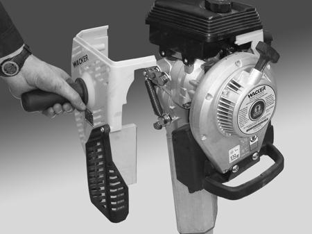
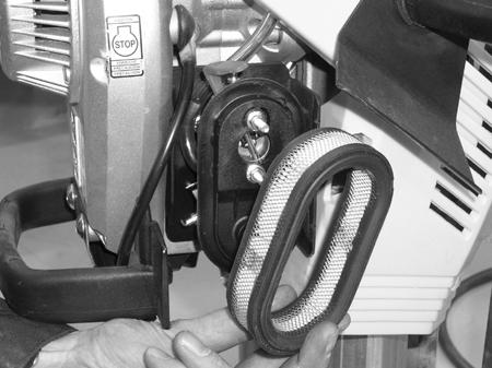
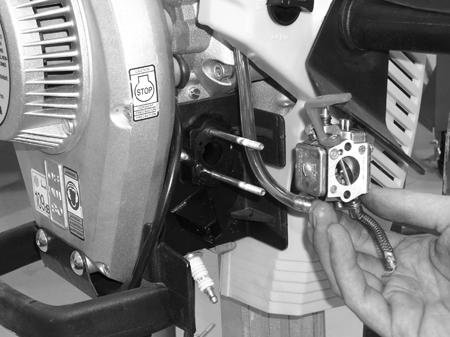
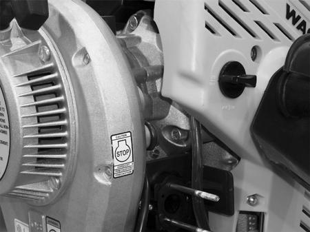
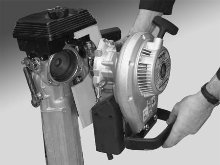
111 WM 80 Repair Disassembly and Assembly a b d c e f wc_gr wc_tx000523gb.fm 111
112 Disassembly and Assembly 10.9 Removing Clutch WM 80 Repair See Graphic: wc_gr This procedure requires special tool P/N , puller. WARNING DO NOT run the engine while it is off the machine unless the clutch has been removed. Running the engine with the clutch attached to the crankshaft will cause the clutch shoes to separate and fly off. Removal: Stop the machine and allow it to cool Remove the engine from the machine. See section Removing Engine Check the condition of the clutch shoes (a) and replace them if necessary. The clutch shoes should be absolutely dry. If oil is present, inspect the engine shaft seal Prevent the clutch from turning and use an air impact wrench and 17 mm socket to loosen the clutch nut (b). If an impact wrench is not available, rap the wrench handle sharply to help break the nut loose. Note: Loosen the nut but do not completely remove it from the engine crankshaft. This will protect the crankshaft threads from the clutch puller screw Screw the clutch puller (P/N ) (c) (or other suitable puller) into the small holes in the clutch and turn the center screw against the end of the crankshaft until the clutch hub breaks free of the taper. Note: When reinstalling the clutch, make sure the taper in the clutch hub and on the engine crankshaft is absolutely free of any oil or grease. Installation: Place the clutch on the engine crankshaft Reinstall the clutch nut and torque to 35 Nm (25 ft.lbs.) Reinstall the engine on the crankcase. Torque the screws to 27 Nm (20 ft.lbs.) Perform an operation check. Clutch should be disengaged with the throttle at the idle position. Engine Speed (idle) (rpm): 1500 ± 200 Clutch Engagement (rpm): 2800 ± wc_tx000523gb.fm

113 WM 80 Repair Disassembly and Assembly c b a wc_gr wc_tx000523gb.fm 113
114 Disassembly and Assembly WM 80 Repair WM 80 Exploded View wc_gr wc_tx000523gb.fm
115 WM 80 Repair WM 80 Components Disassembly and Assembly See Graphic: wc_gr Ref Description Ref Description 1 Set-cylinder 21 Needle bearing 2 Stud M6x18 22 Screw M5x55 3 Stud M5x20 23 Ignition module 4 Piston 24 Sleeve 5 Piston ring 25 Screw M5x20 6 Wrist pin 26 Nut M12x1.5 7 Retaining ring 27 Washer 8 Gasket 28 Screw M5x20 9 Screw M6x60 29 Flywheel housing 10 Spark plug 30 Flywheel 11 Spark plug cap 31 Locknut M3 12 Ignition cable 32 Cap 13 Sealing ring 33 Cable guide 14 Screw M5x8 34 Terminal post 15 Shaft seal 35 Screw M3x20 16 Nut M5 36 Woodruff key 17 Crankcase 37 Screw M6x12 18 Gasket 38 Lock washer 19 Ball bearing 39 Starter complete 20 Crankshaft 40 Terminal flag wc_tx000523gb.fm 115
116 Disassembly and Assembly WM 80 Cross Section WM 80 Repair wc_gr wc_tx000523gb.fm
117 WM 80 Repair Disassembly and Assembly WM 80 Cross Section Components See Graphic: wc_gr Ref Description Ref Description 1 Crankcase 9 Piston 2 Crankcase gasket 10 Piston rings 3 Recoil starter 11 Cylinder 4 Flywheel key 12 Connecting rod 5 Flywheel fan 13 Cylinder gasket 6 Fan hood 14 Crankshaft 7 Retaining ring 15 Shaft seal 8 Piston wrist pin 16 Crankshaft bearing wc_tx000523gb.fm 117
118 Disassembly and Assembly Vacuum Testing Cylinder WM 80 Repair See Graphic: wc_gr This procedure requires the use of test kit P/N , an 1/8 NPT hose barb, new gaskets, and a vacuum pump. Note: For clarity, the engine is shown removed from the machine Remove the air cleaner or air cleaner duct Remove the carburetor. See section Removing Carburetor Remove the muffler Using the existing nuts, attach a new exhaust gasket (a) and the exhaust cover (b) over the exhaust port Using the existing nuts, attach a new intake gasket (c) and the intake cover (d) over the intake port. Attach an 1/8-inch NPT hose barb (e) to the intake cover Be sure that the spark plug and all the hardware securing the cylinder to the crank case is tight Attach the vacuum pump (f) to the hose barb. Operate the pump until kpa (5 7 inches) of vacuum is reached. Observe the gauge for any drop in pressure. A drop of more than 0.25 kpa (1 in.) of vacuum per minute is considered unacceptable. All leaks should be located and rectified To locate a leak, squirt small amounts of oil around all possible leak areas. Reapply the vacuum and watch the gauge for a decrease in the leak rate. Replace the cylinder, hardware, or gaskets as needed. 118 wc_tx000523gb.fm


119 WM 80 Repair Disassembly and Assembly a c e b d f wc_gr wc_tx000523gb.fm 119
120 Disassembly and Assembly Cylinder and Piston Removal WM 80 Repair See Graphic: wc_gr The cylinder and cylinder head is of a one-piece design providing easy access to the cylinder and piston and eliminating the need for a head gasket. The cylinder bore is coated with a wear-resistant metal alloy. This allows heat to dissipate faster than using a cast iron cylinder sleeve. The lower operating temperature prevents the oil in the fuel/oil mixture from dissipating as readily, thus improving engine lubrication. To remove the cylinder and piston, carry out the following procedure: Disconnect and remove the spark plug from the engine Disconnect the fuel line and the throttle cable from the engine Remove the muffler, air filter, and carburetor from the engine. Remove the engine from the machine Remove the four M6 screws (b) holding the cylinder to the crankcase and remove the cylinder Remove the retaining rings (c) securing the piston pin (d) to the piston (e). Push the pin from the piston and remove the piston from the connecting rod Remove the piston rings (f) from the piston. Be careful not to break the rings or damage the ring s grooves when removing the rings Remove the needle bearing (g) from the connecting rod. 120 wc_tx000523gb.fm

121 WM 80 Repair Disassembly and Assembly b c f e d c g wc_gr wc_tx000523gb.fm 121
122 Disassembly and Assembly Cylinder and Piston Inspection WM 80 Repair See Graphic: wc_gr Ring Gap: Remove the cylinder from the crankcase. Check the ring gap at the lower part of the cylinder by placing the ring (h) in the cylinder and measuring the gap between the ends of the ring. If the ring gap is greater than 1.2 mm (0.047 in.) the rings need to be replaced. Ring gaps should measure as follows: New: mm ( in.) Maximum: mm ( in.) Piston Wear: Piston wear is checked with a visual inspection. If the piston is noticeably worn or scored, it should be replaced. Typically, a piston will last through two sets of rings before requiring replacement. Cylinder Wear: Remove the cylinder from the crankcase. Carefully remove any carbon deposits from the cylinder head, exhaust port, and piston head. Inspect the piston and cylinder visually for scoring. Check the cylinder coating for wear. If it has worn through, replace the cylinder. NOTICE: Do not use a glaze breaker or hone on the cylinder. The metal alloy coating of the cylinder will be destroyed and render the cylinder useless. Measure the cylinder wear by measuring the ring gap at the top of the cylinder and again at the bottom. Use a new ring if possible and the same ring for both measurements. If the difference in the two measurements is greater than 0.2 mm (0.008 in.), the cylinder is worn beyond its limits. Replace the cylinder, piston, and rings. Typically, a cylinder will last through two pistons before requiring replacement. 122 wc_tx000523gb.fm
123 WM 80 Repair Disassembly and Assembly h wc_gr wc_tx000523gb.fm 123
124 Disassembly and Assembly Cylinder and Piston Installation WM 80 Repair See Graphic: wc_gr This procedure requires the use of special tool P/N , ring compressor. It also requires the use of new retaining rings, P/N Remove all old gasket material from the cylinder and crankcase. Inspect the mating surfaces of the cylinder and crankcase for any deep scratches or defects which could prevent a good seal. The cylinder and crankcase must form an airtight seal for the engine to perform properly Install the rings (a) on the piston (b) with the notch in rings facing up, and around the pins (c) that are located in each groove of the piston Install the needle bearing (d) in the connecting rod (e). Position the piston over the connecting rod with the arrow (f) stamped on the top of the piston pointing toward the exhaust side of the engine. Slide the wrist pin (g) in place. Secure the wrist pin with two new retaining rings (h). Do not re-use old retaining rings Position the cylinder gasket (i) on the crankcase and lubricate the piston rings and cylinder bore with 2-cycle engine oil Using ring compressor P/N to hold the rings in place, carefully slide the cylinder over the piston Secure the cylinder to the crankcase using M6 screws. Tighten the screws in the sequence shown and torque to 10 Nm (7 ft.lbs.). 124 wc_tx000523gb.fm

125 WM 80 Repair Disassembly and Assembly c a f b e g h d i wc_gr wc_tx000523gb.fm 125
126 Disassembly and Assembly Inspecting Connecting Rod and Crankshaft WM 80 Repair See Graphic: wc_gr With the cylinder removed, check the needle bearing (a) for damage or wear. Replace it if necessary Insert the wrist pin into the needle bearing and check for excessive play. Replay the needle bearing and/or the wrist pin if necessary Check the connecting rod (b) for any vertical play there should be none. Side play is allowable. If any vertical play is present, the complete crankshaft assembly must be replaced Turn the crankshaft by hand and check that the shaft bearings rotate freely. Replace worn or damaged bearings If a piston ring is broken, inspect the crankcase and bearings to be sure that no ring pieces have become lodged inside the engine. Flush the crankcase using an oil-rich fuel mixture. Note: When replacing the crankshaft, the crankshaft bearings and the needle bearing for the piston wrist pin must also be replaced. 126 wc_tx000523gb.fm


127 WM 80 Repair Disassembly and Assembly a OK OK b wc_gr wc_tx000523gb.fm 127
128 Disassembly and Assembly Disassembling Crankcase WM 80 Repair See Graphic: wc_gr Remove the clutch, starter, flywheel, cylinder, and piston. Place the nut back on the shaft to protect shaft threads Remove eight M5 screws (a) which secure the crankcase halves together Secure the crankcase in vice or equivalent. Note: It is suggested that M8 cap screws (b) be screwed into clutch end of crankcase. Then secure crankcase in vise (c) using the capscrews Heat the area (d) of the crankcase around the bearing using a propane torch While the crankcase is hot, tap firmly on the end of the crankshaft with a plastic mallet to remove the crankcase from the shaft. Support the crankcase shell/crankshaft (e) as it slides from the other half of the crankcase shell. The bearing (f) will remain intact on the shaft Support the other half of the crankcase shell/crankshaft. Heat the area of the crankcase around the bearing using a propane torch While the crankcase is hot, tap firmly on the end of the crankshaft with a plastic mallet to remove the crankshaft (g) from the crankcase shell Once the crankcase shell halves have cooled, remove the crankshaft seals (h) from each shell. 128 wc_tx000523gb.fm

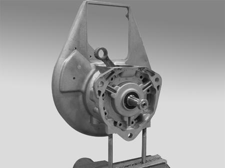
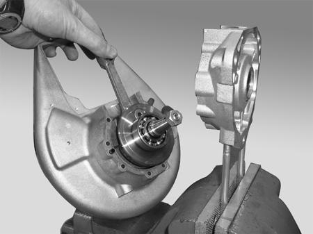
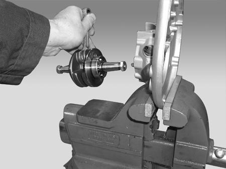
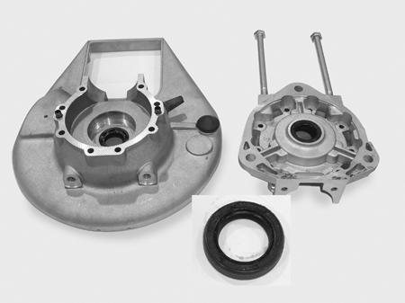
129 WM 80 Repair Disassembly and Assembly a b c e d f g h wc_gr wc_tx000523gb.fm 129
130 Disassembly and Assembly Assembling Crankcase WM 80 Repair See Graphic: wc_gr This procedure requires a propane torch or equivalent heat source Lubricate the shaft seals (a) using 2-cycle engine oil. Position one of the seals over the bore in the crankcase shell (b) with the open side of the seal facing in. Make sure the seal is laying straight and press it into the bore, from the outer side, using pusher P/N Press until the outer edge of the seal is flush with the outer edge of the crankcase shell. In the same manner, press the other shaft seal into the other crankcase shell (c) Lubricate both crankshaft bearings with 2-cycle engine oil Heat the area (d) of the crankcase shell (b) using a propane torch. Heat the area to approximately C ( F). Be careful not to damage the seal when heating. Install the crankshaft into the warm crankcase shell. Note: The crankshaft should slide easily into the crankcase shell if heated sufficiently Lightly oil gasket (e) with 2-cycle engine oil. Position the gasket over the roll pins (f) in crankcase shell (c) Heat crankcase shell (c) using a propane torch (In the same manner as crankcase shell (b) in step 3.) Heat the area to approximately C ( F). Be careful not to damage the seal when heating. Install the crankshaft into the warm crankcase shell and push the crankcase shells together until they are tight Allow the preassembled crankcase to cool. When cool, secure it together with M5 screws (g) and nuts (h). Tighten the screws in steps and torque to 6.5 Nm (5 ft.lbs.) After the crankcase is assembled, tap it lightly on the end to release any bearing tension. Check the assembly by turning the crankshaft by hand. The crankshaft should turn easily Trim off any excess gasket material from the outside of the engine and at the top of the cylinder mounting surface. 130 wc_tx000523gb.fm


131 WM 80 Repair Disassembly and Assembly a g f a c e e d a f b h wc_gr wc_tx000523gb.fm 131
132 Disassembly and Assembly Crankshaft Bearings WM 80 Repair See Graphic: wc_gr Press Method Removal: This procedure requires special tools P/N , split ring puller (a); and P/N , crank support tube (b). It also requires the use of an Arbor press or equivalent Place the two halves of the split ring puller around the bearing on the crankshaft. If necessary, tap gently on the ring halves to seat them under the bearing Secure the complete assembly in the crank support tube Using an Arbor press, press on the end of the crankshaft until the bearing breaks free. Note: Support the crankshaft as it slides from the bearing. Extractor Method Removal: If a press is not available, the bearings can be pulled from the shaft using the following special tools: P/N , extractor (c); P/N , half shell (d); and P/N , holding ring (e) Assemble the tools to the bearing as shown Turn the center bolt of the extractor until the bearing breaks free of the shaft. 132 wc_tx000523gb.fm


133 WM 80 Repair Disassembly and Assembly a b e c d wc_gr wc_tx000523gb.fm 133
Repair Manual. Rammer BS 50 / BS 60 / BS 70 BS 500 / BS 600 / BS 700 BS 65 / BS 650 DS 70 / DS 720
 Repair Manual Rammer BS 50 / BS 60 / BS 70 BS 500 / BS 600 / BS 700 BS 65 / BS 650 DS 70 / DS 720 EN 5000114549 11 0411 5 0 0 0 1 1 4 5 4 9 Copyright notice Copyright 2011 by Wacker Neuson Corporation.
en Vibroplate VP 1550 (RAW) OPERATOR S MANUAL
 OPERATOR S MANUAL") www.wackergroup.com 0157759en 001 0703 Vibroplate VP 1550 (RAW) OPERATOR S MANUAL 0 1 5 7 7 5 9 E N VP 1550 (RAW) Table of Contents 1. Foreword 2 2. Safety Information 3 2.1 Laws Pertaining to Spark Arresters...
www.wackergroup.com 0157759en 001 0703 Vibroplate VP 1550 (RAW) OPERATOR S MANUAL 0 1 5 7 7 5 9 E N VP 1550 (RAW) Table of Contents 1. Foreword 2 2. Safety Information 3 2.1 Laws Pertaining to Spark Arresters...
en Backpack Vibrator BV 35A-P BV 50A-P OPERATOR S MANUAL
 0171881en 003 0708 Backpack Vibrator BV 35A-P BV 50A-P OPERATOR S MANUAL 0 1 7 1 8 8 1 E N BV Table of Contents 1. Foreword 5 2. Safety Information 6 2.1 Laws Pertaining to Spark Arresters... 6 2.2 Operating
en Walk-Behind Trowels CT 36 CT 48 REPAIR MANUAL
 www.wackergroup.com 0163091en 003 1007 Walk-Behind Trowels CT 36 CT 48 REPAIR MANUAL 0 1 6 3 0 9 1 E N CT Repair Foreword This manual covers machines with Item Number: 0009438, 0009439, 0009442, 0009443,
en Generator GP 2500A OPERATOR S MANUAL
 0163727en 005 0509 Generator GP 2500A OPERATOR S MANUAL 0 1 6 3 7 2 7 E N DANGER CARBON MONOXIDE Using a generator indoors CAN KILL YOU IN MINUTES. Generator exhaust contains carbon monoxide (CO). This
en 003 Generator GV 5600A OPERATOR S MANUAL
 www.wackergroup.com 0170813en 003 0108 Generator OPERATOR S MANUAL 0 1 7 0 8 1 3 E N DANGER CARBON MONOXIDE Using a generator indoors CAN KILL YOU IN MINUTES. Generator exhaust contains carbon monoxide
Repair Manual. Roller RD 12
 Repair Manual Roller RD 12 EN 5000192242 02 0912 5 0 0 0 1 9 2 2 4 2 Copyright notice Copyright 2012 by Wacker Neuson Production Americas LLC All rights, including copying and distribution rights, are
Owner s/operator s Manual
 Water Pump MP2533E2 Owner s/operator s Manual Completely read and understand this manual before using this product. Foreword This Owner s/ Operator s Manual is designed to familiarize the operator with
Operator s Manual. Inverter Generator. GPi en
 Operator s Manual Inverter Generator GPi 1700 0179739en 002 0311 0 1 7 9 7 3 9 E N Copyright notice Copyright 2010 by Wacker Neuson Corporation. All rights, including copying and distribution rights, are
PORTABLE TRASH PUMPS MDP200
 PORTABLE TRASH PUMPS MDP200 OPERATING & PARTS MANUAL INTRODUCTION This manual provides information and procedures to safely operate and maintain the engine and pump. For your own safety and protection
OPERATING INSTRUCTIONS. Vibratory Plate Compactor SPHZR106A
 SMHZR106-02 Before using the machine, please read this manual carefully. OPERATING INSTRUCTIONS Vibratory Plate Compactor SPHZR106A Table of Contents 1. Foreword.... 1. 2. Safety Information.. 1 2.1 Laws
SECTION 4 - FUEL SYSTEMS AND CARBURETION
 SECTION - FUEL SYSTEMS AND CARBURETION FUEL SYSTEMS - - - - - - - - - - - - - - - - - - - - - - - - - - - - - - - - - - - - - - - - - - - - - - - - - - - - - - - - - - - - - -62 FUEL PUMP - - - - - - -
GV 2500A GV 3800A GV 5600A GV 6600A
 0171887en 002 0609 Generator GV 2500A GV 3800A GV 5600A GV 6600A REPAIR MANUAL 0 1 7 1 8 8 7 E N GV Generator Repair Foreword Machines covered by this manual Machine Item Number GV 2500A 0620286, 0620542
5. FUEL SYSTEM 5-0 FUEL SYSTEM UXV 500
 5 FUEL SYSTEM 5 SERVICE INFORMATION------------------------------------------------ 5-02 TROUBLESHOOTING----------------------------------------------------- 5-03 FUEL TANK -----------------------------------------------------------------
PF-4000, PF-4010, PF-4210 MULTI-PURPOSE ENGINE
 PF-4000, PF-4010, PF-4210 MULTI-PURPOSE ENGINE Date 09-26-01 Supplier To The Outdoor Power Equipment Industry ISM, Inc. 1028 4 th Street SW Auburn, WA 98001 Phone: (253) 333-1200 Fax: (253) 333-1212 WWW.TANAKA-USA.COM
en 002 Engine WM 130 WM 170 WM 270 OPERATOR S MANUAL
 www.wackergroup.com 0156647en 002 0405 Engine WM 130 WM 170 WM 270 OPERATOR S MANUAL 0 1 5 6 6 4 7 E N WM 130/170/270 Table of Contents 1. Foreword 2 2. Emission Control System Information 3 3. Safety
PORTABLE TRASH PUMPS MTP200 MTP300 MTP400
 PORTABLE TRASH PUMPS MTP200 MTP300 MTP400 OPERATING & PARTS MANUAL INTRODUCTION This manual provides information and procedures to safely operate and maintain the engine and pump. For your own safety and
5. FUEL SYSTEM 5-0 FUEL SYSTEM MXU 250R/300R
 5 FUEL SYSTEM 5 SERVICE INFORMATION------------------------------------------------ 5-2 TROUBLESHOOTING----------------------------------------------------- 5-3 FUEL TANK -----------------------------------------------------------------
Voltmaster Centrifugal Trash Pumps
 Voltmaster Centrifugal Trash Pumps Model TSP2, TSP3 and TSP4 Owner s Manual February 2011 Table of Contents 1 Introduction............................ 1 1.1 Read before using..................... 1 1.2
1100W PORTABLE GENERATOR
 1100W PORTABLE GENERATOR MODEL NO: G1200 PART NO: 8010110 OPERATION & MAINTENANCE INSTRUCTIONS LS0312 INTRODUCTION Thank you for purchasing this CLARKE 1100W Portable Generator. Before attempting to use
en Pump PTS 4V PTK 4 REPAIR MANUALS
 www.wackergroup.com 0163209en 001 0207 Pump PTS 4V PTK 4 REPAIR MANUALS 0 1 6 3 2 0 9 E N PT 4 Repair Foreword This manual covers machines with Item Number: 0007683, 0007691, 0007692 Operating / Parts
720W PORTABLE GENERATOR
 720W PORTABLE GENERATOR MODEL NO: G720 PART NO: 8857800 OPERATION & MAINTENANCE INSTRUCTIONS LS0214 INTRODUCTION Thank you for purchasing this CLARKE 720W Portable Generator Before attempting to use this
AC2T & AC2T-ES INDUSTRIAL GASOLINE AIR COMPRESSOR
 AC2T & AC2T-ES INDUSTRIAL GASOLINE AIR COMPRESSOR INDUSTRIAL GAS AIR COMPRESSOR OPERATOR S MANUAL IT IS ETREMELY IMPORTANT TO READ AND UNDERSTAND THE ENTIRE CONTENTS OF THIS OPERATOR S MANUAL BEFORE ATTEMPTING
Table of Contents. Safety symbols... 3 Assembly 6. Operation Maintenance Troubleshooting 11. Storage. 12. Notes. 13
 Table of Contents Safety symbols... 3 Assembly 6 Operation... 8 Maintenance... 10 Troubleshooting 11 Storage. 12 Notes. 13 2 Safety Information Attention; this machine can be dangerous! All operators should
AG-HA-2500N GASOLINE GENERATOR
 AG-HA-2500N GASOLINE GENERATOR OWNER S MANUAL BEFORE OPERATING THIS EQUIPMENT PLEASE READ THESE INSTRUCTIONS CAREFULLY (I)WARNING 1. Read the operator s instruction manual. 2. Attention! Exhaust gases
MODELS 3100,3130,3160, 1300, 1330,1360 EXHAUST SYSTEM
 MODELS 3100,3130,3160, 1300, 1330,1360 EXHAUST SYSTEM WALBRO CARBURETOR "WA" SERIES MUFFLER REMOVAL CARBURETOR REMOVAL The muffler assembly should beremoved periodically to inspect for excessive carbon
Operator s Manual. Inverter Generator. GPi 1700
 Operator s Manual Inverter Generator GPi 1700 EN 5000186370 05 0813 5 0 0 0 1 8 6 3 7 0 Copyright notice Copyright 2013 by Wacker Neuson Production Americas LLC All rights, including copying and distribution
KING CANADA 950W PORTABLE GENERATOR MODEL: KCG-951G INSTRUCTION MANUAL COPYRIGHT 2011 ALL RIGHTS RESERVED BY KING CANADA TOOLS INC.
 KING CANADA 950W PORTABLE GENERATOR MODEL: KCG-951G INSTRUCTION MANUAL COPYRIGHT 2011 ALL RIGHTS RESERVED BY KING CANADA TOOLS INC. WARRANTY & SERVICE INFORMATION 1-YEAR LIMITED WARRANTY FOR THIS 950W
EZT715-EZT750 Owner's Manual
 EN EZT715-EZT750 Owner's Manual ESS FRC IMPORTANT: Read all safety precautions and instructions carefully before operating equipment. Refer to operating instruction of equipment that this engine powers.
5. FUEL SYSTEM FUEL SYSTEM 5-0
 5 FUEL SYSTEM 5-0 SERVICE INFORMATION GENERAL INSTRUCTIONS SERVICE INFORMATION...5-1 CARBURETOR INSTALLATION...5-9 TROUBLESHOOTING...5-1 PILOT SCREW ADJUSTMENT...5-10 CARBURETOR REMOVAL...5-2 AUTO BYSTARTER...5-3
Gasoline Inverter Generator
 user manual Gasoline Inverter Generator table of contents Preface Introduction... Safety Information Exhaust fumes are poisonous... Fuel is highly flammable and poisonous... Engine and muffler may be hot...
3. INSPECTION/ADJUSTMENT
 3 SERVICE INFORMATION...3-0 FINAL REDUCTION GEAR OIL...3-7 MAINTENANCE SCHEDULE...3-2 DRIVE BELT...3-7 FUEL FILTER...3-3 BRAKE SHOE...3-8 THROTTLE OPERATION...3-3 BRAKE ADJUSTING NUT...3-8 AIR CLEANER...3-4
No part of this publication may be reproduced without written permission.
 Thank you for purchasing a Honda generator. This manual covers operation and maintenance of the EB3000 and EB4000 generators. All information in this publication is based on the latest product information
AIR COMPRESSOR OPERATING INSTRUCTION AND PARTS LIST
 AIR COMPRESSOR OPERATING INSTRUCTION AND PARTS LIST BELT TYPE IMPORTANT PLEASE MAKE CERTAIN THAT THE PERSON WHO IS TO USE THIS EQUIPMENT CAREFULLY READS AND UNDERSTANDS THESE INSTRUCTIONS BEFORE STARTING
8500M INDUSTRIAL GASOLINE GENERATOR OPERATOR S MANUAL
 8500M INDUSTRIAL GASOLINE GENERATOR OPERATOR S MANUAL IT IS EXTREMELY IMPORTANT TO READ AND UNDERSTAND THE ENTIRE CONTENTS OF THIS OPERATOR S MANUAL BEFORE ATTEMPTING TO OPERATE THE PRODUCT. THIS EQUIPMENT
HOT WASHER MODEL NO: KING 125 OPERATION & MAINTENANCE INSTRUCTIONS PART NO: LS1009
 HOT WASHER MODEL NO: KING 125 PART NO: 7320170 OPERATION & MAINTENANCE INSTRUCTIONS LS1009 INTRODUCTION Thank you for purchasing this Hot Washer. This machine is a portable, high pressure power washer,
AIR CLEANER GENERAL REMOVAL. 1CAUTION Do not run engine without filter element in place. Debris could be drawn into the engine causing damage.
 AIR CLEANER GENERAL The air cleaner prevents foreign material from entering the carburetor and engine by trapping airborne dust and dirt in the filter element. Service air cleaner filter element every
Part No FJ180V KAI. 4-stroke air-cooled gasoline engine OWNER, S MANUAL
 Part No. 99920-2280-02 FJ180V KAI 4-stroke air-cooled gasoline engine OWNER, S MANUAL SAFETY AWARENESS FOREWORD TABLE OF CONTENTS Whenever you see the symbols shown below, heed their instructions! Always
Earth Auger MAG500 MAG500RS
 Earth Auger MAG500 MAG500RS US Owner s/operator s Manual Completely read and understand this manual before using this product. - 0 - Foreword This Owner s/ Operator s Manual is designed to familiarize
TP300 INDUSTRIAL TRASH PUMP OPERATOR S MANUAL
 TP300 INDUSTRIAL TRASH PUMP OPERATOR S MANUAL IT IS EXTREMELY IMPORTANT TO READ AND UNDERSTAND THE ENTIRE CONTENTS OF THIS OPERATOR S MANUAL BEFORE ATTEMPTING TO OPERATE THE PRODUCT. THIS EQUIPMENT IS
RedGum GP160 Splitter. Owner s Manual
 RedGum GP160 Splitter Owner s Manual Product Description & Intended Purpose: This Log Splitter / Wood Splitter is an outdoor product that splits wood logs for use as fuel in a fireplace or a woodstove.
KT715-KT745 Owner's Manual
 EN KT715-KT745 Owner's Manual ESS FRC IMPORTANT: Read all safety precautions and instructions carefully before operating equipment. Refer to operating instruction of equipment that this engine powers.
TILLOTSON LTD., CLASH INDUSTRIAL ESTATE, TRALEE, CO. KERRY, IRELAND PHONE: FAX:
 TILLOTSON LTD., CLASH INDUSTRIAL ESTATE, TRALEE, CO. KERRY, IRELAND PHONE: +353 66 7121911 FAX: +353 66 7124503 e-mail: sales@tillotson.ie SERIES SERVICE MANUAL INTRODUCTION The gasoline engine industry
PORTABLE INVERTER GENERATOR MODEL
 3200Watts PORTABLE INVERTER GENERATOR MODEL #104612 Operation Manual This safety alert symbol identifies important safety messages in this manual. Failure to follow this important safety information may
Operation Manual. 10 Mini-Cultivator MODEL #
 10 Mini-Cultivator MODEL # 103350 Operation Manual This safety alert symbol identifies important safety messages in this manual. Failure to follow this important safety information may result in serious
Water pump Owner's Manual
 Water pump Owner's Manual Safety Precautions I. General Safeguards Please read this operation manual to have a thorough understanding of the content there before use the product. Failure to do so may lead
12. CARBURETOR 12-0 CARBURETOR VITALITY 50
 12 12 CARBURETOR SERVICE INFORMATION (2-STROKE)... 12-2 SERVICE INFORMATION (4-STROKE)... 12-3 THROTTLE VALVE (2-STROKE)... 12-5 CARBURETOR (2-STROKE)... 12-7 AIR SCREW ADJUSTMENT (2-STROKE)... 12-13 REED
en Generator, Non-CARB GPS 8500 GPS 9700 OPERATOR S MANUAL
 0176674en 002 0809 Generator, Non-CARB GPS 8500 GPS 9700 OPERATOR S MANUAL 0 1 7 6 6 7 4 E N DANGER CARBON MONOXIDE Using a generator indoors CAN KILL YOU IN MINUTES. Generator exhaust contains carbon
OPERATION & MAINTENANCE INSTRUCTIONS
 WARNING Read the instructions before using the machine PETROL DRIVEN POWER WASHER MODEL NO: TIGER1700 PART NO: 7320054 OPERATION & MAINTENANCE INSTRUCTIONS LS0511 2 INTRODUCTION Thank you for purchasing
COLT 2310, 2510, AND 2712 COM PACT TRACTORS CHAPTER 9 TROUBLESHOOTING AND ANALYSIS
 COLT 2310, 2510, AND 2712 COM PACT TRACTORS CHAPTER 9 TROUBLESHOOTING AND ANALYSIS 9-A-1 UPON RECEIVING ANENGINE FORRE- PAIR. Learn the history of the unit from the customer. While the customer is present
5.5KVA GENERATOR MODEL NO: PG6500DVES OPERATION & MAINTENANCE INSTRUCTIONS PART NO: LS0616
 5.5KVA GENERATOR MODEL NO: PG6500DVES PART NO: 8857810 OPERATION & MAINTENANCE INSTRUCTIONS LS0616 INTRODUCTION Thank you for purchasing this CLARKE 5.5KVA Generator. Before attempting to use this product,
1-1/2 DIAMETER WATER PUMP
 1-1/2 DIAMETER WATER PUMP 2.2HP/79.8cc Engine MODEL # 101099 Operation Manual This safety alert symbol identifies important safety messages in this manual. Failure to follow this important safety information
SV471-SV601 Owner's Manual
 EN ESS SV471-SV601 Owner's Manual FRC IMPORTANT: Read all safety precautions and instructions carefully before operating equipment. Refer to operating instruction of equipment that this engine powers.
Operation Manual. All Terrain Power Cart MODEL #
 All Terrain Power Cart MODEL # 101872 Operation Manual This safety alert symbol identifies important safety messages in this manual. Failure to follow this important safety information may result in serious
ZT710-ZT740 Owner's Manual
 EN ZT710-ZT740 Owner's Manual ESS FRC IMPORTANT: Read all safety precautions and instructions carefully before operating equipment. Refer to operating instruction of equipment that this engine powers.
GENERATOR MODEL NO: FG2500 OPERATION & MAINTENANCE INSTRUCTIONS PART NO: LS0114
 GENERATOR MODEL NO: FG2500 PART NO: 8857727 OPERATION & MAINTENANCE INSTRUCTIONS LS0114 INTRODUCTION Thank you for purchasing this CLARKE Generator. Before attempting to use this product, please read this
Airless Spray Gun INSTRUCTIONS DP psi (345 bar) Maximum Working Pressure
 Maximum Working Pressure") INSTRUCTIONS DP-6376 Airless Spray Gun 5000 psi (345 bar) Maximum Working Pressure INSTRUCTIONS This manual contains important warnings and information. READ AND KEEP FOR REFERENCE. Table of Contents Warnings......................................
INSTRUCTIONS DP-6376 Airless Spray Gun 5000 psi (345 bar) Maximum Working Pressure INSTRUCTIONS This manual contains important warnings and information. READ AND KEEP FOR REFERENCE. Table of Contents Warnings......................................
3. INSPECTION/ADJUSTMENT
 3 3 INSPECTION/ADJUSTMENT SERVICE INFORMATION -------------------------------------------- 3-1 MAINTENANCE SCHEDULE ---------------------------------------- 3-2 FUEL LINE/FUEL FILTER -------------------------------------------
McCULLOCH. Stroke. 30 mm (1.2 in.) 30 mm (1.2 in.) 30 mm (1.2 in.) 30 mm (1.2 in.)
 30 mm (1.2 in.) 30 mm (1.2 in.) 30 mm (1.2 in.)") SERVICE MANUAL Model Eager Beaver 2010, Mac 3210 Silver Eagle 2012 Eager Beaver 2014, Mac 3214, Silver Eagle 2014 Eager Beaver 2016, Mac 3216, Silver Eagle 2016 Bore Stroke DispL (2.1 cu. in.) (2.1CU.
SERVICE MANUAL Model Eager Beaver 2010, Mac 3210 Silver Eagle 2012 Eager Beaver 2014, Mac 3214, Silver Eagle 2014 Eager Beaver 2016, Mac 3216, Silver Eagle 2016 Bore Stroke DispL (2.1 cu. in.) (2.1CU.
OPERATION, MAINTENANCE AND OVERHAUL INSTRUCTIONS FOR PB18 SERIES PORTABLE PUMPS
 WATEROUS COMPANY Form No. F 2058 South St. Paul, Minnesota 55075 January, 1992 OPERATION, MAINTENANCE AND OVERHAUL INSTRUCTIONS FOR PB18 SERIES PORTABLE PUMPS Printed in U.S.A. Waterous Company F 2058
4. FUEL SYSTEM CK 1 4-0
 4 4 4-0 SERVICE INFORMATION... 4-1 FLOAT LEVEL INSPECTION... 4-5 TROUBLESHOOTING... 4-2 CARBURETOR INSTALLATION... 4-6 THROTTLE VALVE DISASSEMBLY... 4-3 THROTTLE VALVE ASSEMBLY... 4-6 CARBURETOR REMOVAL...
GENERATOR MODEL NO: FG3005 OPERATION & MAINTENANCE INSTRUCTIONS PART NO: LS0413
 GENERATOR MODEL NO: FG3005 PART NO: 8857707 OPERATION & MAINTENANCE INSTRUCTIONS LS0413 INTRODUCTION Thank you for purchasing this CLARKE Generator. Before attempting to use this product, please read this
INSPECTION/ADJUSTMENT
 3 3 INSPECTION/ADJUSTMENT SERVICE INFORMATION----------------------------------------------------------------------- 3-1 MAINTENANCE SCHEDULE-------------------------------------------------------------------
1200W INVERTER GENERATOR
 1200W INVERTER GENERATOR MODEL NO: IG1200 PART NO: 8877070 OPERATION & MAINTENANCE INSTRUCTIONS LS0117 INTRODUCTION Thank you for purchasing this CLARKE 1200W Inverter Generator. Before attempting to use
Pump Owner s Manual. PLEASE! Read All Instructions Carefully Before Installing Pump
 Pump Owner s Manual PLEASE! Read All Instructions Carefully Before Installing Pump Guarantee Associate Engineering Corporation warrants that pumps purchased from them will be free of defects in material
4. FUEL SYSTEM 4-0 FUEL SYSTEM NEXXON 50
 4 FUEL SYSTEM SERVICE INFORMATION ------------------------------------------------ 4-2 TROUBLESHOOTING----------------------------------------------------- 4-3 AIR CLEANER REMOVAL -----------------------------------------------
WORKSHOP MANUAL. 63,4 cm³ chainsaws
 WORKSHOP MANUAL General failures analysis Suggested tools I. Emak tool kit II. Compression tester: to check thermal group III. Electronic tachometer: for 2 and 4 stroke engines, measurement range from
LDG6000SA DIESEL GENERATOR OWNERS MANUAL
 LDG6000SA DIESEL GENERATOR OWNERS MANUAL BEFORE OPERATING THIS EQUIPMENT PLEASE READ THESE INSTRUCTIONS CAREFULLY Preface Thank-you for purchasing this generator. This operation manual contains information
PB18 SERIES PORTABLE PUMPS
 PB18 SERIES PORTABLE PUMPS OPERATION, MAINTENANCE AND OVERHAUL INSTRUCTIONS MODELS: PB18-G2015B PB18-2515 PB18-2515B PB18-3030 PB18-3030C WATEROUS COMPANY SOUTH ST. PAUL, MINNESOTA 55075 U.S.A. SAFETY
9500M. WARNING American Fab of SC, LLC Travelers Rest, SC OPERATOR S MANUAL INDUSTRIAL GASOLINE GENERATOR
 9500M INDUSTRIAL GASOLINE GENERATOR OPERATOR S MANUAL WARNING American Fab of SC, LLC Travelers Rest, SC It is extremely important to read and understand the entire contents of this operator s manual before
Propane torch. Model Assembly And Operation Instructions
 Propane torch Model 39953 Assembly And Operation Instructions Due to continuing improvements, actual product may differ slightly from the product described herein. 3491 Mission Oaks Blvd., Camarillo, CA
CH940-CH1000 CV940-CV1000 Owner's Manual
 CH940-CH1000 CV940-CV1000 Owner's Manual IMPORTANT: Read all safety precautions and instructions carefully before operating equipment. Refer to operating instruction of equipment that this engine powers.
Read instructions carefully and follow rules for safe operation. Failure to do so could result in serious injury. Fradan Manufacturing Corp.
 OPERATOR MANUAL FRADAN POWER BLOWERS Part No. 888-011-222-0 Read instructions carefully and follow rules for safe operation. Failure to do so could result in serious injury. Fradan Manufacturing Corp.
TILLOTSON LTD., CLASH INDUSTRIAL ESTATE, TRALEE, CO. KERRY, IRELAND PHONE: FAX:
 TILLOTSON LTD., CLASH INDUSTRIAL ESTATE, TRALEE, CO. KERRY, IRELAND PHONE: +353 66 7121911 FAX: +353 66 7124503 e-mail: sales@tillotson.ie HU SERIES SERVICE MANUAL INTRODUCTION To keep apace of new market
SAVE THESE INSTRUCTIONS
 OPERATION MANUAL WARHORSE IMPORTANT SAFETY INSTRUCTIONS WARNING: Failure to observe these instructions can cause personal injury to machine operator or bystanders. WARNING: Asphyxiation Hazard. An improperly
HD675, HD775 Owner's Manual
 EN ESS HD675, HD775 Owner's Manual FRC IMPORTANT: Read all safety precautions and instructions carefully before operating equipment. Refer to operating instruction of equipment that this engine powers.
GP 6600A GPS 6600A CARB
 0171950en 002 0609 Generator GP 6600A GPS 6600A CARB OPERATOR S MANUAL 0 1 7 1 9 5 0 E N DANGER CARBON MONOXIDE Using a generator indoors CAN KILL YOU IN MINUTES. Generator exhaust contains carbon monoxide
LAWN MOWER OWNER S MANUAL
 LAWN MOWER OWNER S MANUAL Woodies SKU: 1153279 & 1153280 CAUTION: Read and follow all Safety Rules and Instructions before operating this equipment Thank you for choosing our Gasoline Lawnmower. 1 To ensure
3. INSPECTION/ADJUSTMENT
 SERVICE INFORMATION...3-0 FINAL REDUCTION GEAR OIL...3-7 MAINTENANCE SCHEDULE...3-2 DRIVE BELT...3-7 FUEL FILTER...3-3 BRAKE SHOE...3-8 THROTTLE OPERATION...3-3 BRAKE ADJUSTING NUT...3-8 AIR CLEANER...3-4
7. FUEL SYSTEM ('04 - '05)
") 7. FUEL SYSTEM ('04 - '05) SYSTEM COMPONENTS 7-2 CARBURETOR DISASSEMBLY 7-81 SERVICE INFORMATION 7-3 CARBURETOR ASSEMBLY 7-14 TROUBLESHOOTING 7-4 CARBURETOR INSTALLATION 7-21 AIR CLEANER HOUSING 7-5 PILOT
7. FUEL SYSTEM ('04 - '05) SYSTEM COMPONENTS 7-2 CARBURETOR DISASSEMBLY 7-81 SERVICE INFORMATION 7-3 CARBURETOR ASSEMBLY 7-14 TROUBLESHOOTING 7-4 CARBURETOR INSTALLATION 7-21 AIR CLEANER HOUSING 7-5 PILOT
SINGLE STAGE SNOW ENGINE SERVICE MANUAL
 RESIDENTIAL PRODUCTS SINGLE STAGE SNOW ENGINE SERVICE MANUAL LC154FS / LC154FDS (87cc) About this Manual This service manual was written expressly for Toro service technicians. The Toro Company has made
TILLOTSON LTD., CLASH INDUSTRIAL ESTATE, TRALEE, CO. KERRY, IRELAND PHONE: FAX:
 TILLOTSON LTD., CLASH INDUSTRIAL ESTATE, TRALEE, CO. KERRY, IRELAND PHONE: +353 66 7121911 FAX: +353 66 7124503 e-mail: sales@tillotson.ie HR SERIES SERVICE MANUAL INTRODUCTION Tillotson has developed
YK1900i DIGITAL INVERTER GASOLINE GENERATOR OWNER S MANUAL PLEASE READ THIS MANUAL CAREFULLY. IT CONTAINS IMPORTANT SAFETY INFORMATION.
 YK1900i DIGITAL INVERTER GASOLINE GENERATOR OWNER S MANUAL PLEASE READ THIS MANUAL CAREFULLY. IT CONTAINS IMPORTANT SAFETY INFORMATION. PREFACE Thank you for purchasing YANGKE generator. This manual covers
ENGINE DRIVEN 3 FULL TRASH PUMP
 ENGINE DRIVEN 3 FULL TRASH PUMP MODEL NO: PF75 PART NO: 7230165 OPERATION & MAINTENANCE INSTRUCTIONS ORIGINAL INSTRUCTIONS LS0117 ISS 2 INTRODUCTION Thank you for choosing this Clarke Pump. The function
IMPORTANT INFORMATION
 Table of Contents IMPORTANT INFORMATION Section 1B - Maintenance MAINTENANCE 1 B Specifications........................... 1B-1 Special Tools........................... 1B-2 Mercury/Quicksilver Lubricants
HOFFMANN POWER PRODUCTS PARTS LIST 2014
 HOFFMANN POWER PRODUCTS PARTS LIST 2014 VIBRATORY PLATE COMPACTOR ALL PARTS ARE SUBJECT TO STANDARD HOFFMANN TERMS AND CONDITIONS OF SALE 2010 Replacement parts are not manufactured, sold or warranted
Draft. Proprietary Photo. Record Engine Information to reference when ordering parts or obtaining warranty coverage. Engine Model.
 Engine Model XXxxxx Liquefied Petroleum Gas (LPG) or LPG / Natural Gas (NG) Fueled Operation Manual TP-6901 Important: Proprietary Photo Read all safety precautions and instructions carefully before operating
2013 IMPCO Technologies, Inc. Page 1 of 20 EPR Repair Kit Instructions (PPI-122, Rev-B)
") EPR Repair Kit Instructions PPI-122 (Rev-B) A. Introduction: This document covers the repair of the Electronic Pressure Regulator (EPR) used on Spectrum III series fuel systems. These instructions will
EPR Repair Kit Instructions PPI-122 (Rev-B) A. Introduction: This document covers the repair of the Electronic Pressure Regulator (EPR) used on Spectrum III series fuel systems. These instructions will
Backpack Sprayer. Use and Care Manual
 Backpack Sprayer Use and Care Manual BACKPACK SPRAYER CAUTION: Read and follow all instructions Do Not Return This Backpack To The Store For Help, Information or Parts, Call : 1-800-311-9903 The Fountainhead
695XL SERVICE MANUAL
 695XL SERVICE MANUAL TABLE OF CONTENTS SECTION SECTION TITLE PAGE NUMBER SERVICE MANUAL USE... 3 1 TOOLS... 4 2 POWER CUTTER SPECIFICATIONS... 5 3 SERIAL NUMBER LOCATION... 6 4 SPARE PARTS DIAGRAM... 7
3KVA DUAL VOLTAGE GENERATOR MODEL NO: PG3800DV
 3KVA DUAL VOLTAGE GENERATOR MODEL NO: PG3800DV PART NO: 8857815 OPERATION & MAINTENANCE INSTRUCTIONS LS1016 INTRODUCTION Thank you for purchasing this CLARKE 3KVA Dual Voltage Generator. Before attempting
NOTES FOR SAFETY OPERATOR-ONLY.
 NOTES FOR SAFETY Both the parents and their child must fully understand everything in this manual before riding. This vehicle is for OPERATOR-ONLY. This vehicle is only designed for operation on level,
GASOLINE GENERATOR SET SPG8000 PORTABLE GENERATOR INSTRUCTION MANUAL IMPORTANT!
 GASOLINE GENERATOR SET SPG8000 PORTABLE GENERATOR INSTRUCTION MANUAL IMPORTANT! Please make certain that persons who are to use this equipment thoroughly read and understand these instructions and any
Illustrated Parts List. Model Series. TYPE NUMBERS 0113 through TABLE OF CONTENTS
 Illustrated Parts List Model Series 219800 TYPE NUMBERS 0113 through 4389. TABLE OF CONTENTS FORM MS5709 REV P 11/08/2012 REPLACES FORM MS5709 REV N 04/24/2012 FILE IN SECT. 2 OF SERVICE MANUAL 219800
PROPANE TORCH WITH TURBO BURNER
 PROPANE TORCH WITH TURBO BURNER MODEL 91894 ASSEMBLY AND OPERATING INSTRUCTIONS 3491 Mission Oaks Blvd., Camarillo, CA 93011 Visit our Web site at http://www.harborfreight.com TO PREVENT SERIOUS INJURY,
680GC SERVICE MANUAL ICS- Blount Inc Specifications and pricing are subject to change without notice. P/N REV12Sep2012
 680GC SERVICE MANUAL i TABLE OF CONTENTS SECTION SECTION TITLE PAGE NUMBER SERVICE MANUAL USE 2 1 TOOLS 3 2 SAW SPECIFICATIONS 4 3 SERIAL NUMBER LOCATION 5 4 SPARE PARTS DIAGRAM (TORQUE AND LOCTITE ) 6
SPECIFICATIONS Horsepower: 1.5 HP Running Maximum PSI: 125 PSI Tank Capacity: 15 Gallons CFM: 6 40 PSI 5 90 PSI
 15 GALLON AIR COMPRESSOR Model: 7678 DO NOT RETURN TO STORE Please call 800-348-5004 for parts and service CALIFORNIA PROPOSITION 65 WARNING: You can create dust when you cut, sand, drill or grind materials
Owner s Manual ELECTRIC GENERADORS R7100DP / G7100G
 Owner s Manual ELECTRIC GENERADORS R7100DP / G7100G Thank you for choosing a generator set of our company. This manual contains the information on how to do that. Please read it carefully before operating.
SPECIFICATIONS TEST AND ADJUSTMENT SPECIFICATIONS SPECIFICATIONS ENGINE FD620D, K SERIES
 ENGINE FD620D, K SERIES SPECIFICATIONS SPECIFICATIONS TEST AND ADJUSTMENT SPECIFICATIONS Engine Oil Pressure Sensor Activates............................... 98 kpa (14.2 psi) Oil Pressure While Cranking
KS530-KS595 Owner's Manual
 EN ESS KS530-KS595 Owner's Manual FRC IMPORTANT: Read all safety precautions and instructions carefully before operating equipment. Refer to operating instruction of equipment that this engine powers.