DIAGNOSTIC MANUAL (EMS)
|
|
|
- Jasper Lawson
- 6 years ago
- Views:
Transcription


1 DIAGNOSTIC MANUAL (EMS) MAN RELEASED BY - TECHNICAL PUBLICATION CELL MAHINDRA & MAHINDRA LTD. Rev 1 DECEMBER 2010 All information contained in this manual is most up-to-date at the time of publication. However, specifications and procedures are subject to change without notice. This manual is strictly meant for restricted circulation Mahindra & Mahindra Ltd. All rights reserved. This book may not be reproduced or copied, in whole or in part, without the written permission of Mahindra & Mahindra Ltd.
2 About the Diagnostic Manual The diagnostic manual outlines the detailed procedures to troubleshoot complaints related to the CRDe components in THAR CRDe BS-IV vehicle. Since the CRDe components and system is sensitive and requires certain level of understanding for troubleshooting; only a trained authorized persons can work on the CRDe system in conjunction with M&M diagnostic tool. The manual consists of Trouble shooting and diagnosis of DTCs (Defect Trouble Codes) Use of Smart Tester for Flashing. Circuit diagram for complete system. In spite of best efforts to make the manual error-free, a few errors could have inadvertently crept in. If you identify errors, functional or typographical, please inform your TEKline, pillay.ajay@mahindra.com or jose.davis@mahindra.com. Suggestions to improve the manual and make it more user-friendly are also welcome Mahindra & Mahindra Ltd. All rights reserved. This book may not be reproduced or copied, in whole or in part, without the written permission of Mahindra & Mahindra Ltd.
3 MAN Contents How to use this manual Overview of the in-vehicle communication network Recommended Trouble shooting Process Warranty & Other Information Connecting and Disconnecting Diagnostic Tool IQA/IMA code Programming EMS ECU Re-Programming/Flashing List of DTC codes Actuator Tests Symptom Based Diagnosis Conformity Check-Resistance Values Wiring Diagram
4 MAN How to Use this manual If the DTC code is known, then go to the Index of DTC code, and click on the group under which the DTC appears. The codes/groups are hyperlinked to the respective trouble shooting chart/pages. The following is the structure of the Diagnostic Manual Sketch/Photo of the sensor/actuator involved Brief description about the sensor/actuator and its functions Possible defect codes related to that sensor/actuator rmal/abnormal operating conditions of the sensor/actuator, possible causes and vehicle/engine reactions Related circuit diagram and connectors. Trouble shooting process Always use the diagnostic manual along with the vehicle s wiring manual (MAN-00106). The Diagnostic tester has the ability to test certain actuators. There are certain complaints for which no DTC codes are generated. The trouble shooting procedure for the same is covered in the Symptom based Diagnosis.
5 MAN Overview of the in-vehicle communication network Diagnostic Connector (DLC) K - Line Engine (EMS ECU)
6 MAN Recommended Trouble Shooting Process Customer complaint Record/Understand Customer Verbatim What happened? When it happened? What was the event before that? Does it happen all the time? Does it happen only in some condition? Search for Published TEKalert in TEKnet. Follow DTC based diagnosis Contact TEKliner with TAR (Technical Assistance Request) Warranty & Other Information All failures/complaints encountered on EMS ECU need to be reported through a Common Rail Failure Report (CrFR)/Service Complaint Report (SCR). Replacement of the EMS ECU requires approval of the TEKline. Ensure that a TAR is raised # in the TEKnet website for approval, attaching the CrFR/SCR. While raising a warranty claim, the TAR no should be quoted on the warranty claim. # Only a trained and certified CoTEK can raise a TAR (in TEKnet website)
7 MAN IQA/IMA Code Programming An ECU controlled engine needs precise metering of fuel. Due to manufacturing tolerances, each injector deviates slightly from its idealized behavior. Thus, each injector has a correction factor, which is engraved on top of it, in the form of a seven character alphanumeric code. This is known as an IQA code/ima code. For optimal performance of the engine, the ECU needs to know the IQA code/ima code of each injector. This information is programmed into the ECU when the vehicle is manufactured. However, if you need to replace an injector(s), then the IQA code/ima code for that new injector has to be updated in the ECU. As a first step, you need to select the cylinder number of the injector being replaced. After the cylinder number is selected by clicking on the check-button next to the number, the IQA code/ima code should be entered in the box provided. Click the button to the right of the text box. If the Injector code is valid and accepted by the ECU, a message is displayed, indicating that the operation is performed successfully. A message Invalid IQA code will be displayed, if an incorrect IQA/IMA code is keyed in. IQA codes are case sensitive. Programming IQA codes is an extremely important activity. In order to ensure that the correct code has been entered and that it has been entered in the correct cylinder, SMART tester allows you to verify the codes that you have entered. Select an injector, and click the button below the Verify line in figure. The IQA codes present in the ECU will be read back and displayed in the text box before this button. It is recommended that you carry out the verification activity whenever you change an IQA code. PLEASE ENSURE TO PROGRAM IQA/IMA CODES WHEN YOU REPLACE AN INJECTOR, ECU or ENGINE. The following are the fonts of the alphanumeric characters of the IQA/IMA code, as etched on the injectors.
8 MAN EMS ECU Programming/Flashing The EMS ECU required to be flashed in the following conditions BLANK ECU 1. Procure blank EMS ECU from spare part dept. 0315CM0031N ECU WITHOUT ETK EDC16C39** ** Check for the correct/latest part no in parts catalogue/technical Service Bulletins. 2. Flash the EMS ECU dataset with a latest dataset as per TSB or at the advice of TEKline. REFLASHING AN EXISTING ECU 1. Flash the EMS ECU with the correct/latest dataset. The matrix of the vehicles and the related latest dataset will be released through TSB - if in doubt ask the TEKline. 2. Wrong dataset flashing may result in vehicle not starting and can lead to ECU failure. Software Version ECU Type Dataset ID Model Will be released through TSB THAR CRDe tes 1. Ensure that the there is no communication breakdown once the flashing begins. Check Python connections are secure. 2. Ensure that the SMART tester has - Enough battery reserve/connected to AC power Screen saver/battery saver mode turned off, Vehicle s ignition is ON Battery terminals connected securely. Battery earth connection is good. 3. Never touch the ECU pins by hand/finger.

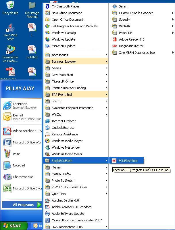
9 MAN RE-PROGRAMMING PROCEDURE Connect using the Python1BConfig0404. Click on to the ECU flash tool
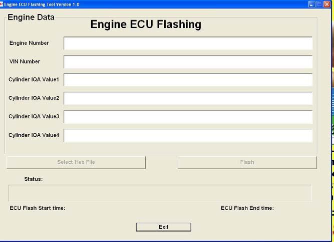
10 MAN Write the correct 17 digit VIN
 Select the applicable dataset and")

11 MAN Click on Select Hex File (Refer to latest TSB) Select the applicable dataset and click open Click Flash After completion of flashing, switch OFF the ignition for 2 minutes and switch it ON
12 MAN List of DTC codes Group Code Label Page P-0123 Voltage above upper limit APP1 P-0122 Voltage below lower limit. 18 P-1120 Plausibility with APP2 violated. APP2 P-0223 Voltage above upper limit P-0222 Voltage below lower limit. P-1220 Plausibility with APP1 violated 22 P-1221 Accelerator Pedal signal not plausible with brake Camshaft P-0340 camshaft signal P-0341 Wrong camshaft signal 25 Crankshaft P-0335 crankshaft signal P-0336 Wrong crankshaft signal 28 Air Flow Air temperature P-0103 Voltage above upper Limit P-0102 Voltage below lower Limit P-0113 Voltage above upper limit. P-0112 Voltage below lower limit
13 MAN Group Code Label Page P-0193 Voltage above upper limit. P-0192 Voltage below lower limit. 41 P-1192 Maximum positive Rail pressure deviation exceeded Rail Pressure P-1193 Maximum positive Rail pressure deviation exceeded concerning the set flow value 44 P-1194 Maximum negative rail pressure deviation with metering unit on lower limit is exceeded 47 P-1195 Minimum rail pressure exceeded 48 P-1196 Maximum rail pressure exceeded 49 K Line communication with Diagnostic 50 P-0406 Short Circuit Battery EGR P-0405 Short Circuit Ground P-0403 Load P-0404 Excess Temperature 52 Error path of offset P-1340 Offset between camshaft and crankshaft 55 Fuel Temperature Sensor P-0182 P-0183 Voltage above upper limit Voltage below lower limit 58
14 MAN Group Code Label Page P-1252 Short Circuit to Battery Metering Unit P-1253 Short Circuit to Ground P-1250 Load P-1251 Excess Temperature 61 Main relay Battery P-121A P-121B P-0563 P-0562 P-1792 Main relay does not open in time Main relay opens too early Voltage above upper limit Voltage below lower limit. Brake signal is defective Brake Switch P-1791 Brake signals not plausible 68 Clutch Switch P-0704 Clutch signal is not plausible 71 Coolant Temp Sensor(CTS) P-0118 Voltage above upper limit P-0117 Voltage below lower limit 74 CTS absolute & dynamic test P-2558 P-1126 Minimum Temperature not reached within time limit. Minimum temperature or temperature raise no reached within time limit 77 Atm pressure sensor P-0108 P-0107 Voltage above upper limit Voltage below lower limit 79
15 MAN Group Code Label Page Injector Energizing Time Communication monitoring P-1623 P-1625 P-161F P-1621 P-162A Below lower limit of enegising time- Injector # 1 Below lower limit of enegising time- Injector # 2 Below lower limit of enegising time- Injector # 3 Below lower limit of enegising time- Injector # 4 Communication error of CJ Controller & TPU Monitoring P-1659 Deviation between TPU and system time 82 ECU Monitoring P-1638 Set, if error-counter of Watchdog or controller are not plausible or the system must shut down 83 P-162B EEPROM: error during last read operation EEPROM Monitoring P-162C EEPROM: error during last write operation 84 Tachometer Signal P-162D P-160C P-160D EEPROM: default value used Short Circuit to Battery Short Circuit to Ground 85 P-160E Load P-1608 Short circuit to battery Coolant temperature output P-1609 P-160A Short circuit to ground load 88 P-160B Excess temperature
16 MAN Group Code Label Page P-1210 Chip-specific errors : CY33X internal reset / clock loss / under voltage P-1211 Chip-specific errors: CY33X is unlocked / CY33X init error P-1212 Chip-specific errors:cy33x is in Test mode ECU P-1213 Chip-specific errors: CY33X SPI communication error /checksum/read back 91 P-1214 Chip-specific errors - >CY33X internal parity error P-1215 Chip-specific errors - >CY33X internal program flow error P-1216 Chip-specific errors - >CY33X check of inv. YSEL during ON failed P-1217 Chip-specific errors - >CY33X ON timeout for at least 1 cylinder Monitoring communication P-1664 The fault path contains the supervision of the SPI-Handler Set, if SPIcommunication failed 92
17 MAN Group Code Label Page Test of redundant shut off paths during P-1641 initialization: Watch dog switch off path defect Power stage Monitoring P-1642 Test of redundant shut off paths during initialization: Voltage monitoring upper limit shut off path defect 93 P-1643 Test of redundant shut off paths during initialization: Voltage monitoring lower limit shut off path defect Power Stage Voltage Monitoring Sensor Supply Monitoring 1 Sensor Supply Monitoring 2 P-1631 P-1632 P-1644 P-1645 P-1646 P-1647 P-1654 (Hardware) CJ940 upper limit: internal supply voltage upper limit (Hardware) 94 CJ940 lower limit: internal supply voltage lower limit Voltage above upper limit Voltage below lower limit Voltage above upper limit Voltage below lower limit Short Circuit to Battery System Lamp P-1655 P-1656 Short Circuit to Battery Load 100 P-1657 Excess Temperature
18 MAN Group Code Label Page P-1650 Short Circuit to Battery MIL Lamp P-1651 Short Circuit to Battery P-1652 Load 103 P-1653 Excess Temperature Terminal 15 ( Ignition Switch) P-1658 Terminal T15 signals detected 106 P-0503 Exceeding of the maximum vehicle speed Vehicle Speed P-0500 HW signal for vehicle speed not valid 107 P-0501 Vehicle speed not plausible with injection mass and engine speed EEPROM Error P-183E EEPROM Error 109 P-0201 Injector bank 1: short circuit Injector Bank 1- Specific Error P-1201 Injector bank 1: short circuit on Low Side to ground 110 P-1203 Injector bank 1 specific error depending on application P-1204 Injector bank 1 notclassifiable error
19 MAN Group Code Label Page P-1205 Injector bank 1specific warning : depending on application Injector Bank 1- Specific Warning P-1206 P-1207 Injector bank 1specific warning : depending on application Injector bank 1specific warning open load 111 P-1208 Injector bank 1specific warning depending on application Home Screen for Actuator 112 ACT # 1 System lamp Actuator test 113 Actuator Test ACT # 2 Coolant Overheat Lamp 114 ACT # 3 Air Conditioning 115 ACT # 4 EGR 116 ACT # 5 Boost Pressure Actuator (BPA) 117 Symptom Based Diagnosis SBD #1 SBD # 2 Vehicle not starting & no error codes 118 Vehicle not starting also may get P1192/

20 MAN Accelerator Pedal Module 1 P-0123 P-0122 P-1120
21 MAN P-0123 P-0122 P-1120 Accelerator Pedal Module 1 Description: The Accelerator pedal module (APM) mounts in place of accelerator pedal and is connected to the ECU by wires. The APM sensor is a variable resistor (potentiometer) whose resistance changes according to the pedal position. ECU applies a reference voltage to the APM sensor and then measures the voltage that is present on the APM sensor signal circuit. The ECU uses the APM sensor signal for further calculation of fuelling & other engine operational parameters. DTC P-0123 P-0122 P-1120 Diagnostic item Voltage above upper limit Voltage below lower limit. Plausibility with APP2 violated. DTC detection condition rmal Operation The Accelerator pedal module (APM) outputs a voltage, which is proportional to the Position of accelerator pedal. The ECU checks whether the voltage output by the Accelerator pedal module is within a specified range. In addition, it checks that the voltage output does not become too large while the engine is in idling. Probable cause Open or shorted Accelerator pedal module circuits, loose or wrongs connections. Accelerator pedal module failed or maladjusted. Proper Performance Sensor output voltage has continued to between 0 to 5V, varying accelerator pedal position. Malfunction; out-of-range With the changing Accelerator pedal position, the sensor output voltage has continued to be 5V or 0V. Reaction: The engine speed not varying with changing accelerator pedal position. (Constant 1200 rpm) The system lamp is continuously on.
22 MAN P-0123 P-0122 P-1120
23 MAN Test Procedure APP1 1. Connect the Smart Tester to diagnostic connector. 2. Turn Ignition Switch ON. 3. Verify either P0123 or P122 or P1120 are present. P-0123 P-0122 P-1120 Turn Ignition switch OFF & disconnect Accelerator Pedal connector. Turn the Ignition ON & measure voltage between terminal 2 & terminal 3 of the APP1 (from the APP1 connector side.) It should be 5 ± 0.3 V Is it? Turn Ignition OFF Measure the continuity between terminal K09 in ECU and Terminal 4 of connector Continuity is OK. (resistance below 1 Ω) Measure the continuity between K45 & 2 ( Voltage) K30 and 3 ( ground) Repair the damaged line/ connection Clear code Verify that the complaint has been eliminated. Reconnect. Before reconnection check that the pins are not bent or oxidation has not taken place. Clear the codes Does the problem persist? Check the APP 1 resistance in both the state 0% & 100% Repair the damaged line/ connection Clear code Verify that the complaint has been eliminated. Is it within the specifications Clear the code. Replace the Accelerator pedal Module Verify that the complaint has been eliminated.
24 MAN Accelerator Pedal (APP2) Description: P-0223 P-0222 P-1220 P-1221 The Accelerator pedal module (APM) mounts in place of accelerator pedal and is connected to the ECU by wires. The APM sensor is a variable resistor (potentiometer) whose resistance changes according to the pedal position. ECU applies a reference voltage to the APM sensor and then measures the voltage that is present on the APM sensor signal circuit. The ECU uses the APM sensor signal for further calculation of fuelling & other engine operational parameters. DTC P-0223 P-0222 P-1220 P-1221 Diagnostic item Voltage above upper limit Voltage below lower limit. Plausibility with APP1 violated Accelerator Pedal signal not plausible with brake DTC detection condition Proper Performance Sensor output voltage has continued to between 0 to 2.5V, with varying accelerator pedal position. Malfunction; out-of-range With the fully pressed Accelerator pedal module, the sensor output voltage has continued to be 2.5V or 0 for 4 sec. Reaction The engine speed not varying with changing accelerator pedal position. (Constant 1200 rpm) The system lamp is continuously on. Probable cause Open or shorted Accelerator pedal module circuits, loose or wrong connections. Accelerator pedal module failed or maladjusted.
25 MAN P-0223 P-0222 P-1220 P-1221
26 MAN Test Procedure APP2 1. Connect the Smart Tester to diagnostic connector. 2. Turn Ignition Switch ON. 3. Verify that either P0223/P0222/P1220 / or P1221 is present. P-0223 P-0222 P-1220 P-1221 Turn Ignition switches OFF & disconnect Accelerator pedal connector. Turn the Ignition ON & measure voltage between terminal 2 & terminal 3 of the APP2 (from the APP2 connector side.) It should be 2.5 ± 0.15 V Is it? Turn Ignition OFF Measure the continuity between terminal K31 in ECU and Terminal 6 of connector. Continuity is OK? (resistance below 1 Ω) Measure the continuity between K46 & 1 ( Voltage) K08 and 5 ( ground) Repair the damaged line/ connection. Clear code Verify that the complaint has been eliminated. Reconnect. Before reconnection check that the pins are not bent or oxidation has not taken place. Clear the codes. Does the problem persist? Check the APP 2 resistance in both the state 0% & 100% Is it within the specifications Repair the damaged line/ connection. Clear code. Verify that the complaint has been eliminated. Clear code. Verify that the complaint has been eliminated. Replace the Accelerator pedal Module
 point of the # 1 cylinder in the compression stroke. Which allows the ECU to determine when to start the injection. DTC detection condition Probable cause")
27 MAN Camshaft Speed Sensor P-0340 P-0341 DTC P-0340 P-0341 Diagnostic item camshaft signal Wrong camshaft signal Description The Hall effect camshaft position sensor senses the Top dead center (TDC) point of the # 1 cylinder in the compression stroke. Which allows the ECU to determine when to start the injection. DTC detection condition Probable cause
28 MAN rmal Operation When the engine is running, the Camshaft Position sensor outputs a pulse signal. The ECU checks whether the pulse signal is input. Malfunction rmal signal pattern has not been input for cylinder identification from the camshaft position sensor signal for 4 sec. (Engine should be cranked to check this error). Open or shorted camshaft position sensor circuit, loose or wrong connection. Camshaft Position sensor malfunction. Reaction Engine will not start System lamp will be continuously on. P-0340 P-0341 Connector View of Cam Phase sensor
29 MAN Connect the Smart Tester to diagnostic connector. 2. Turn Ignition Switch ON. 3. Verify that either P0340 or P0341 are present. Switch off the Ignition. Disconnect the camshaft sensor connector. Turn ON the Ignition. Measure the voltage between the pins in the camshaft connector - Pin. 3 &1. It should be 5 ± 0.3 Volts Is it?
30 MAN P-0340 P-0341 Turn the Ignition OFF Disconnect ECU connector A. Measure the continuity of Ground (between sensor pin no 1 & ECU terminal A20) in the camshaft phase sensor harness. Is it OK? Repair the wires A 11 to Pin.3 &A 20 to Pin. 1. Clear the error codes & verify. Measure the continuity of signal (between sensor pin no 2 & ECU terminal A50) in the camshaft phase sensor harness. Is it OK? Repair the connection. Clear the error codes & verify Check for physical damage to pins or oxidation. Also check if the connectors are moving backwards when inserted. Is it OK? Repair the connection. Clear the error codes & verify. Replace the camshaft phase sensor. Clear the error codes & verify. Repair the connection. Clear the error codes & verify.

31 MAN Crankshaft sensor P-0335 P-0336
32 MAN Crankshaft Sensor P-0335 P-0336 Description - In order that the ECU can control the engine at all the position of the crankshaft must be known so that the cylinder in compression and the timing of the next fuel injection can be calculated. The CKP is an inductive pulse generator, which scans protrusions on the flywheel. Two teeth are missing, and this gap is situated at 90 before TDC. DTC P-0335 P-0336 Diagnostic item crankshaft signal Wrong crankshaft signal DTC detection condition Background When the engine is running, the Crankshaft Position sensor outputs a pulse signal. The ECU checks whether the pulse signal is input while the engine is cranking. rmal Operating condition Engine is being cranked. Malfunction rmal signal pattern has not been input for cylinder identification from the crankshaft position sensor signal for 4 sec. synchronization between crankshaft & camshaft signal. Reaction System lamp continuously on. Engine will not start. If engine is running & this fault occurs, engine will stop immediately. Probable cause Open, shorted or wrong connection crankshaft position sensor circuit. Failed or damaged crankshaft position sensor.
33 MAN P-0335 P-0336 Connector View of Crank/Engine speed sensor
34 MAN Test Procedure ISS P-0335 P Connect the Smart Tester to diagnostic connector. 2. Turn Ignition Switch ON. 3. Verify that either P0335 or P0336 are present. Please verify while cranking the engine. Turn the Ignition switch OFF. Disconnect the crankshaft position sensor connector and also the connector at ECU. Measure the continuity between the sensor terminal 1 and ECU terminal A 27. Is it OK? Measure all terminals for short to Ground. Is it OK? Repair the wires. Clear code & verify the CKP sensor is within normal parameters. Check if the sensor is damaged. If so Repair the connection. change sensor with a known good component. Clear code & verify the CKP sensor is within normal parameters.
35 MAN Air Flow P-0103 P-0102 Description Mass air flow rate is measured by detection of heat transfer from a hot film probe because the change of the mass air flow rate causes change in the amount of heat being transferred from the hot film probe surface to the air flow. The airflow sensor generates a pulse so it repeatedly opens and closes between the 5V voltage supplied from the engine control module. This results in the change of the temperature of the hot film probe and in the change of resistance. DTC P-0103 P-0102 Voltage above upper Limit Voltage below lower Limit Diagnostic item DTC detection condition rmal Operation The HFM sensor outputs a voltage, which corresponds to the intake airflow. The ECU checks whether this voltage is within a specified range. rmal Operating Requirements Ignition switch: ON Malfunction lamp: OFF after 2 Sec Battery voltage is 8V-16V or more. Malfunction The sensor output voltage has continued to be 5V or higher. The sensor output voltage has continued to be 0.5V or lower. Reactions: System lamp will continuously blink. Engine will continue to run with default air flow (depending on Speed & Fuelling) Probable cause Open or shorted HFM sensor circuit, loose or wrong connections. Failed HFM sensor.
36 MAN Bat+ 12V
37 MAN Connector View of HFM sensor
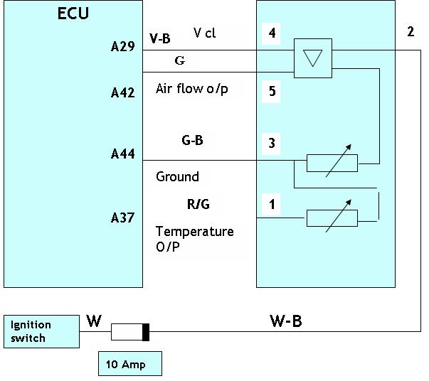
38 MAN Test Procedure HFM 1. Connect the Smart Tester to diagnostic connector. 2. Turn Ignition Switch ON. 3. Verify that either P0103 or P0102 are present. P-0103 P-0102 Turn the ignition OFF Disconnect HFM sensor. Turn the Ignition ON Measure the voltage at the connector between terminal 3 & 4. It should be 5 ± 0.3 Volts Is it Check the output voltage ( with engine running) Signal voltage within the range Is it? Check fuses Check continuity between the A29 & 4 ( voltage) Check continuity between A44 & 3 ( Ground) Repair the open wire. Clear codes and verify that the HFM signal ratio is within limit. Switch off the Ignition Check the connectors if the pins are bent or having oxidation. Clear codes & verify if the codes are eliminated. Check the continuity between the A42 & 5 ( Signal) Rectify Clear codes and verify that the HFM signal ratio is within limit. Check the resistance of the HFM sensor ( between 5 & 3) it should be between to KOhms If not OK. Replace the HFM sensor. Clear codes & verify that the error has been removed.

39 MAN Air Temperature P-0113 P-0112 Air Temperature DTC P-0113 P-0112 Diagnostic item Voltage above upper limit. Voltage below lower limit. Description: The function acquires the raw voltage of the induction air temperature. The raw value is linearised and monitored for compliance with the signal range. The sensor is mounted in HFM. DTC detection condition rmal Operation The HFM temperature sensor outputs a voltage, which corresponds to the temperature of intake airflow. The ECU checks whether this voltage is within a specified range. rmal Operating Requirements Ignition switch: ON Malfunction lamp: OFF after 2 Sec Battery voltage is 8V 16 V. Malfunction The sensor output voltage has continued to be 5V or higher. The sensor output voltage has continued to be 0.2 V or lower. Reactions Engine will run with default air temp of 20 Degrees Centigrade System lamp status for this error is off. Probable cause Open or shorted HFM temperature sensor circuit, loose or wrong connections. Failed HFM temperature sensor.
40 MAN P-0113 P-0112 Connector View of HFM sensor
41 MAN Test Procedure Codes: P0112, P Connect the Smart Tester to diagnostic connector. 2. Turn Ignition Switch ON. 3. Verify that either P0113 or P0112 are present. P-0113 P-0112 Turn the ignition OFF Disconnect HFM sensor Connector. Turn the Ignition ON Measure the voltage between the Terminal 3 & 4 of HFM Sensor Connector. It should be 5 ± 0.3 Volts Is it Check fuses Check continuity between the A29 & 4 ( voltage) Check continuity between A44 & 3 ( Ground) Repair the open wire. Clear codes and verify that error has been eliminated. Measure the continuity between A44 & 3 (ground)is it? Check the continuity between the A37 & 1 ( output signal) Rectify Clear codes & verify. Replace the HFM sensor Rectify Clear codes & verify.
42 MAN Rail Pressure Sensor P-0193 P-0192 DTC P-0193 P-0192 Diagnostic item Voltage above upper limit. Voltage below lower limit. DTC detection condition rmal operation When ignition is ON rail pressure sensor getting supply from ECU. ECU reads the rail pressure in terms of voltage. Engine is starting properly. Building pressure in rail. Probable cause Open, shorted or wrong connection of rail pressure sensor circuit. Rail pressure sensor failed. Malfunction Rail pressure output voltage is below Reaction When ignition is ON system lamp is glowing. Engine is not starting & error is set in ECU Error memory.
43 MAN P-0193 P-0192 Connector View of Rail Pressure Sensor 1. Connect the Smart Tester to diagnostic connector. 2. Turn Ignition Switch ON. 3. Verify that either P-0193 or P-0192 is present. Switch off the Ignition Disconnect the rail pressure sensor connector. Turn ON the Ignition. Measure the voltage between the supply and the ground of the Rail pressure sensor (Pin no 1 & 3 of the RPS connector). It should be 5 ± 0.3 Volts Is it?
44 MAN Check the continuity between the ECU terminal A28 & pin no 3 of the RPS. Continuity between the ECU terminal A43 & pin no 2 of the RPS. Is it OK? Repair the wire. Clear the error codes & verify. Connect the rail pressure sensor connector to sensor. Switch ON the Ignition. Check the output of the RPS ( Should be in range of 500 to 700 mvolts. Is it? Repair the wire. (Check for pins contamination) Clear the error codes & verify. Change the engine speed and check the corresponding increase in RPS value. Rail pressure sensor has failed. ( This can be done using the live data in the Smart Tester ) Is there a change in the RPS. Change the Rail assembly ( RPS is not recommended to service separately) Clear codes & verify Clear codes & verify. Replace rail. Clear codes & verify.
45 MAN Rail Pressure Deviation P-1192 P-1193 DTC P-1192 P-1193 Diagnostic item Maximum positive Rail pressure deviation exceeded Maximum positive Rail pressure deviation exceeded concerning the set flow value DTC detection condition Proper Performance The ECU compares the rail pressure monitored through the RPS against the expected pressure generated due to HPP ( Based on MPROP position and the engine RPM and other parameters) Malfunction; out-of-range If the deviation is more then error is generated. Reaction Engine will be switched OFF Engine can not be started System Check lamp is ON Probable cause Possible Causes Defective fuel tank cap ( improper breathing) Fuel filter Filter assembly Tank strainer choked. Injector stuck in open condition M-Prop valve stuck
46 MAN Test Procedure Rail Pressure Deviation - 1. Connect the Smart Tester to diagnostic connector. 2. Turn Ignition Switch ON. 3. Verify that either P1192/1193 is present.
47 MAN Complaint < 2000 Kms. after filter change. Air lock-do bleeding OK Change Filter & bleed Change Filter assembly along with copper washer t OK Clean tank strainer & fuel line OK Do bleeding at rail in the 4th cylinder injector nut as well as 2nd & 3rd OK Change Injector t OK Check injector overflow OK Change HPP Metering valve can be getting stuck Hint: Try bleeding after removal of the fuel tank cap. If that works, the cap is defective, change it. t OK Change Rail & sensor OK
48 MAN Rail Pressure Deviation P DTC Diagnostic item P-1194 Maximum negative rail pressure deviation with metering unit on lower limit is exceeded. DTC detection condition Proper Performance The negative pressure deviation is within the limit Malfunction; out-of-range The error is reported if the negative rail pressure deviation is more then the specified in the map and at the same time the flow rate is also less Reaction The fuelling is controlled System Check lamp is ON Probable cause Possible Causes Metering unit is stuck in open position, Metering unit without power due to electrical error.
49 MAN Rail Pressure Deviation P DTC Diagnostic item P-1195 Minimum rail pressure exceeded. DTC detection condition Proper Performance The rail pressure is within the limit. Malfunction; out-of-range If the rail pressure falls below engine speed threshold Then the error is generated.. Reaction System Check lamp is ON Probable cause Possible Causes Possible causes in low pressure system : Pressure before gear pump too low, gear pump output too low due to (filter clogged up, leak on low pressure side),. Leakage in the high pressure section due to :- injection nozzle stuck in open position, worn high pressure pump, worn injector, leaking pressure limiting valve
50 MAN Rail Pressure Deviation P DTC Diagnostic item P-1196 Maximum rail pressure exceeded DTC detection condition Proper Performance The rail pressure is within limit Malfunction; out-of-range If rail pressure exceeds the limits specified in the map then the error is generated Probable cause Possible Causes Metering unit is stuck in open position, Metering unit without power due to electrical error Reaction The engine is switched off. System Check lamp is ON
51 MAN K line: Diagnostic connector t connecting Connect the Smart Tester to the Diagnostic Connector. Turn the Ignition ON. Check for the connection on the Smart Tester. Is it OK?
52 MAN Remove the smart tester from the connector. Switch on the Ignition. Check the voltage of the pin no 4/5 & 7 of the connector ( It should show 12 Volts when Ignition is ON and show 0 Volts when Ignition is switched OFF. Is it OK? Diagnostic connector is OK. Check connectivity between K25 and diagnostic connector pin no 7. If is not OK, then repair. Check the voltage. Is it OK. Check the voltage between the connector pins16 & pin 4/5. It should show 12 V continuously. If it is not showing, repair the connection. Otherwise, it indicates less/poor/intermittent contact. Repair Connect smart tester & confirm. Diagnostic hardware is faulty. Change the hardware.
53 MAN EGR power stage Description A pulse-width-modulated signal is the output for the Exhaust Gas Recirculation actuator control. Converting the air control output into duty cycle carries this out. The possible defects are short circuit to battery, ground & no load. P-0406 P-0405 P-0403 P-0404 DTC P-0406 P-0405 P-0403 P-0404 Diagnostic item Short Circuit Battery Short Circuit Ground Load Excess Temperature DTC detection condition Background The ECU checks current flows in the EGR vacuum modulator circuit when the modulator is ON and OFF. Range of check, set conditions. When the EGR modulator is turned OFF, no surge voltage is detected. rmal operation When engine is running per the EGR mapping. System lamp off after 2 sec. Malfunction EGR valve will remain open in case of short circuit to ground fault & remain closed for other fault conditions. Reaction System lamp will blink in case of short circuit to ground condition i.e.p0405.for all other fault condition (related to EGR) lamp will be OFF. Emission will be affect. Probable cause Open or shorted EGR vacuum modulator circuit, loose or wrong connection. EGR vacuum modulator failed EGR control vacuum is too low
54 MAN P-0406 P-0405 P-0403 P-0404 Connector View of EGR Vacuum Modulator
55 MAN P-0406 P-0405 P-0403 P Connect the Smart Tester to diagnostic connector. 2. Turn Ignition Switch ON. 3. Verify that either P0406 or P0405 or P0403 or P0404 are present. Disconnect the EGR control solenoid valve connector. Turn Ignition ON Check the voltage between Ground & EGR control solenoid, valve harness connector terminal. Battery voltage should be present. It should be 12 V when Ignition ON. Is it? Turn Ignition OFF. Disconnect the EGR control solenoid. Disconnect the ECU connector. Check the continuity of the EGR connector with ECU terminal A 60. Is it OK? Verify that the 15 Amp fuse is OK ( same fuse is also used for brake & clutch switch). Repair open or short to Ground on wire between ECU control relay & EGR control solenoid valve. Clear codes & verify. Are the connectors OK ( check for bent pins or oxidation). Rectify the wiring. Clear codes & verify. Replace EGR solenoid with known good Rectify the wiring harness. components. Clear codes & verify EGR solenoid is within limits. If problem persist, replace EGR.
56 MAN P-1340 Error path of offset between camshaft and crankshaft DTC Diagnostic item P-1340 Offset between camshaft and crankshaft DTC detection condition rmal operation Engine is being cranked & started. Malfunction rmal signal pattern has not been input for cylinder identification from the crankshaft position sensor signal and camshaft position sensor signal for 4 sec. synchronization between crankshaft & camshaft signal. Probable cause Mounting of phase sensor, speed sensor or flywheel is loose. Manufacturing defect. Sensors faulty or damaged. Reaction Engine is not being cranked. System lamp will continuously ON.
57 MAN Cam Phase Sensor P-1340 Connector View of Cam Phase sensor Crankshaft/Engine speed sensor Connector View of Cam Phase sensor
58 MAN Connect the Smart Tester to diagnostic connector 2. Turn Ignition Switch ON. 3. Verify that P1340 is present. Turn the Ignition OFF. Disconnect the camshaft & also the crankshaft sensors. P-1340 Check the sensor mounting of crank shaft speed sensor. Check the wiring harness continuity between the cam sensor to ECU & also the crankshaft speed sensor to ECU. Flywheel mounting is OK. ( check for loose dowel and wrong fitment of flywheel) Check the phase sensor for any nicks. Correct the mounting. Clear codes & verify that the signal is within limit. Open the timing cover and check the chain, the adjusters and the plastic guides Clear codes & verify that the signal is within limit. If it is not in limit, change the corresponding sensor. Correct the mounting. Clear codes & verify that the signal is within limit.

59 MAN Fuel Temperature Sensor P-0182 P-0183 Fuel Temperature Sensor Description Fuel temperature sensor acquires the raw value of the fuel temperature. The raw value is linearised and monitored for compliance with the signal range. The sensor is a NTC type DTC P-0182 P-0183 Diagnostic item Voltage above upper limit Voltage below lower limit DTC detection condition Background The fuel temperature sensor converts the engine fuel temperature to a voltage and outputs it. The ECU checks whether the voltage is within a specified range. Malfunction; out-of-range Sensor output voltage has continued to be 5V or higher for 4 sec. Sensor output voltage has continued to be 0.1V or lower for 4 sec. Reaction System lamp will blink continuously. Engine will run with default fuel temp of 20 Deg C. Probable cause Open or shorted Engine fuel temperature sensor circuit, loose or wrong connection Fuel temperature sensor failed.
60 MAN P-0182 P-0183 Connector View of Fuel Temperature Sensor Test Procedure Fuel Temperature Sensor 1. Connect the Smart Tester to diagnostic connector. 2. Turn the Ignition Switch ON. 3. Verify that either P0182 or P0183 are present. Turn the Ignition OFF. Disconnect the FTS connector. Turn the Ignition ON and check the voltage between FTS signal terminal 1 and ground. It should be 5 V ± 0.3 when Ignition ON
61 MAN Is it? Turn the Ignition OFF. Measure continuity between A 52 of ECU & connector terminal 1. Measure continuity between A 51 of ECU & connector terminal 2. Is it OK? Open or short between FTS signal terminal 1 and ECU. Repair as necessary. Connect FTS connector. Turn Ignition ON. Check the voltage of FTS ( at A51 & A52) Is it as per specification? Open or short between FTS signal terminal 1 and ECU. Repair as necessary. Poor terminal contact due to oxidation bent or misplaced terminal. Repair as necessary. Temporarily install a known good FTS and check for proper operation. If problem is corrected, replace FTS. Return vehicle to original condition. Clear all DTC. Verify by driving vehicle with Smart Tester connected and monitor for error codes.
62 MAN Metering unit pump -Power stage P-1252 P-1253 P-1250 P-1251 DTC P-1252 P-1253 P-1250 P-1251 Diagnostic item Short Circuit to Battery Short Circuit to Ground Load Excess Temperature DTC detection condition rmal operation When ignition is ON pump is getting supply from ECU. Engine is starting properly. Probable cause Open, shorted or wrong connection of pump circuit. Malfunction When ignition is ON pump is not getting PWM signal from ECU. Reaction Engine is not starting & error is recorded in ECU error memory. Fuel output is not available from pump. System lamp will remain ON.
63 MAN High Pressure Pump (with fuel metering unit) P-1252 P-1253 P-1250 P-1251 Connector View of Metering Unit 1. Connect the Smart Tester to diagnostic connector. 2. Turn Ignition Switch ON. 3. Verify that either P-1252 or P-1253 or P-1250 or P-1251 is present. Check the connections to the pump. Check that the connections are connected correctly; and that it is not connected in reverse way. Disconnect the pump and ECU connectors. Check the continuity between the ECU terminal A19 and pump terminal 2. Check the continuity between the ACY terminal A49 with pump terminal 1. Is it OK?
64 MAN Check the continuity of ECU connector terminal A49 and A19 with pins 1 & 2 of metering unit Is it OK? Check for terminal contamination. Repair the connection. Clear codes and verify that the error has been eliminated. Error observed due to loose/ intermittent connection. Ensure that the connections are proper. Clear codes and verify the error. There is a possibility of short circuit of battery to ground. Repair the connections. Clear codes & verify. Replace ECU- please take approval from Tekhub The Error Code P 1251 can also be generated if there is leakage in the HPP adaptor. Caution: Till date all the cases investigated have been due to external power supply given directly to Metering unit resulting in ECU track failure. Please check for external tampering or unauthorized work done.
65 MAN Main relay P121A P121B DTC P-121A P-121B Diagnostic item Main relay does not open in time Main relay opens too early DTC detection condition rmal operation While cranking engine will start properly. Malfunction Supply will not come to ECU input. Reaction Engine will not start. communication with smart tester. System check lamp will be on. Probable cause Open, shorted or wrong connection of main relay. Main relay fuse is blown. Relay is not working Engine not cranking Smart Tester is not responding. The check lamp as well as the overheat lamp will not glow
66 MAN Turn the Ignition OFF. Check battery voltage. It should be greater than 8 Volts. Check the 30 Amp fuse. P121A P121B 1. Connect the Smart Tester to diagnostic connector. 2. Turn Ignition Switch ON. 3. Verify that either P121A or P121B is present. Ensure that the main relay is inserted properly in the connector Remove relay. Check the relay externally. Give 12 Volts to terminal 86 and Ground the terminal 85. A clicking sound should be heard. If the sound is not heard, replace the relay. Check if 12 Volts is available at terminal 30, 86 & 85. With respect to ground, terminal 87 should show 0 Volts. Is it OK? Switch ON the Ignition. Measure the voltage at terminal K72 of ECU or terminal 85 of the relay. Is it showing 0 Volts? Measure the voltage at ECU terminal K05/K01/K3. Or at terminal 87 of the relay. It should show 12 Volts. Check the wiring harness. Repair the main relay connections ( check the 30 Amp fuse) Clear codes & verify that the main relay is working properly. Check that the terminal K 28 of ECU is showing 12 Volts. If not repair the connection. Clear codes and verify that the main relay is working properly. Replace the relay with a known good component. Clear codes and verify that the main relay is working properly.

67 MAN Battery P-0563 P-0562 Description: The system voltage has to guarantee to perform diagnosis functions. The Electronic Control Unit (ECU) monitors battery voltage. If this code is set, the System Lamp is off. DTC P-0563 P-0562 Diagnostic item Voltage above upper limit Voltage below lower limit. DTC detection condition Detecting Condition Battery voltage <8 V Enable Condition - main relay failure Battery voltage > 16V Enable Condition - main relay failure Probable cause Charging system not working. Wiring harness to ECU faulty.
68 MAN P-0563 P-0562 Test Procedure Battery Check charging system. Check charging system (including battery) for proper operation. Refer the charging system section in the Electrical. Charging system OK. ( Voltage during cranking should be at least 9 volts) Check earthing ( near the battery- clean the contact and fender for excess paint/rust Check the ECU, problem procedure. Repair or replace.
69 MAN Brake Switch P-1792 P-1791 Description: The function acquires and processes the information via the brake contact and the redundant brake contact. The status message of the brake position is the output. DTC P-1792 P-1791 Diagnostic item Brake signal is defective Brake signals not plausible DTC detection condition Principle The brake switch outputs a voltage, which corresponds to the brake position. The ECU checks whether this voltage is within a specified range (0 or 12V). rmal Operation Ignition switch: ON System lamp: OFF after 2 Sec Battery voltage is 8V 16V. Probable cause Open, shorted, loose or wrong connections of brake switch Wiring. Brake switch damage or faulty Brake switch failed or maladjusted.. Malfunction The sensor output voltage has continued to be 0V in spite of brake pedal being pressed/not pressed The sensor output voltage has continued to 12V in spite of brake pedal being pressed/not pressed Main or redundant switch is not working. Reaction System lamp will be off Cruise control will be deactivated. Engine start stop system will be deactivated
70 MAN P-1792 P-1791
71 MAN Test Procedure Brake switch -- P-1792 P-1791 Codes: P-01792, P Connect the Smart Tester to diagnostic connector 2. Turn Ignition Switch ON 3. Verify that either P1791 or P1792 are present. Disconnect the brake switch connector. Turn Ignition ON and check the supply voltage to brake switch two point connector. It should be 12 V when Ignition ON Is it? Turn the Ignition OFF. Check the 15 Amp fuse after the main relay. Connect the brake switch connector. Check the supply to K01 & K05. Check the voltage at K80 of ECU input pin when the brake is in released position. (Fuses of K01 & K05) Repair connections as necessary. When the brake pedal is pressed then it should be checked at K17. It should be 12 V. Is it? Clear codes & verify. Replace the brake switch with known good component. Check for error. Clear the error memory. Turn Ignition OFF Remove brake switch connection & check continuity between terminal K17 & K80 to brake switch connector. Is it OK? Repair the connection as necessary. Clear the error and verify. Replace the brake switch with known good component
72 MAN Clutch Switch DTC Diagnostic item P-0704 Clutch signal is not plausible P-0704 Description The clutch signal is acquired as a hardware signal. The signal is checked for plausibility using gear information. Error is detected, if there is a valid gear change without the clutch being pressed during the time that elapsed since the last gear change. DTC detection condition rmal Operation The clutch switch outputs a voltage, which corresponds to the clutch position. The ECU checks whether this voltage is within a specified range (0 or 12V). rmal Operating Requirements: Ignition switch: ON Malfunction lamp: OFF after 2 Sec Battery voltage is 8V 16V. Probable cause Open, shorted, loose or wrong connections of brake switch Wiring. Clutch switch failed or maladjusted. Clutch switch damage or faulty. Malfunction The sensor output voltage has continued to be 0V in spite of clutch pedal being pressed/not pressed. The sensor output voltage has continued to 12V in spite of clutch pedal being pressed/not pressed. Reaction: System lamp will be off. Cruise control is deactivated. Low idle governing will be influenced. Engine Start stop system is deactivated.
73 MAN P-0704 Test Procedure Clutch switch 1. Connect the Smart Tester to diagnostic connector. 2. Turn Ignition Switch ON. 3. Verify that error P 0704 is present. Verify that no error related to vehicle speed (vehicle speed sensor related) is present. If present, first attend to those complaints then verify if the error P 0704 is present and then proceed. Disconnect clutch switch connector. Turn the ignition ON. Check supply voltage to clutch switch on connector. It should be 12 V, when Ignition is ON. Is it?
74 MAN Turn Ignition OFF. Check the 15 Amp fuse after the main relay ( this fuse also controls EGR & Brake switch). Connect the clutch switch connector. Check the supply to K01 & K05. Check the voltage at K 58 of the ECU pin, Repair the connections as when the clutch is in released condition. necessary. It should be 12 V. Clear codes & verify. Is it? Clear the codes & verify. If the problem persists, replace with a known good clutch switch. Clear the codes & verify. Turn Ignition OFF. Remove clutch switch connection & check continuity between terminal K58 with clutch switch connector. Is it OK? Repair the connection as necessary. Clear the error memory & verify Replace the clutch switch with known good component.
75 MAN Coolant Temperature Sensor Description: The Coolant temperature sensor (CTS) is located in the coolant pipe of the cylinder head. The CTS sensor is a variable resistor whose resistance changes as the temperature of the engine coolant flowing past the sensor changes.(ntc resistor) When the coolant temperature is low, the sensor resistance is high; when the coolant temperature is high, the sensor resistance is low. The ECU checks CTS voltage and uses the information to help smoothen the engine operation. DTC P-0118 P-0117 Diagnostic item Voltage above upper limit Voltage below lower limit P-0118 P-0117 DTC detection condition Background The engine coolant temperature sensor converts the engine coolant temperature to a voltage and outputs it. The ECU checks whether the voltage is within a specified range. In addition, it checks that the engine coolant temperature (signal) does not drop while the engine is warming up. Malfunction; out-of-range Sensor output voltage has continued to be 5V or higher for 4 sec. Sensor output voltage has continued to be 0.1V or lower for 4 sec. Probable cause Open or shorted Engine Coolant Temperature sensor circuit, or loose or wrong connection Engine Coolant Temperature sensor failed. Reaction: System lamp will be on. Engine will continue to run with water temperature of 120 deg C.. Power will be reduced
76 MAN P-0118 P-0117 Connector View of Coolant Temperature Sensor Test Procedure Coolant Temperature Sensor -- Codes: P-0118, P-0117, 1. Connect the Smart Tester to diagnostic connector 2. Turn Ignition Switch ON Verify DTC P0118 or P0117 are present. Turn the Ignition OFF Disconnect the CTS connector. Turn Ignition ON and check the voltage between CTS signal terminal 1 and ground. It should be 5 V when Ignition ON Is it?
77 MAN P-0118 P-0117 Turn the Ignition OFF Measure continuity between A 58 of ECU & connector terminal 1 Measure continuity between A 41 of ECU & connector terminal 2 Is it OK Open or short between CTS signal terminal 1 and ECU Repair as necessary. Connect CTS connector Turn Ignition ON Check the voltage of CTS Is it as per specification Open or short between CTS signal terminal 1 and ECU Repair as necessary. Poor terminal contact due to oxidation, bent or misplaced terminal Repair as necessary Temporarily install a known good CTS and check for proper operation. If problem is corrected, replace CTS. Return vehicle to original condition. Clear all DTC. Verify by driving vehicle with Smart Tester connected and monitor for error codes.
78 MAN Coolant temperature sensor absolute & dynamic test P-2558 P-1126 Description - When the engine is switched ON then the ECU detects the temperature. After that when the engine runs then the temperature output on a time frame is detected and compared against predetermined slope. DTC P-2558 P-1126 Diagnostic item Minimum Temperature not reached within time limit. Minimum temperature or temperature raise no reached within time limit DTC detection condition Proper Performance The coolant temperature rises to a specified temperature within a specific time period. It also compares the rate of rise with a defined rate of rise Malfunction; out-of-range The coolant temperature do not rise enough within a specific time period, The coolant temperature do not reach a warmed-up fuel control temperature within a specific time period. Probable cause Defective temperature sensor. Thermostat stuck in open condition Thermostat removed. Reaction System check lamp : OFF
79 MAN Test Procedure - P-2558 P-1126 Remove the connector of the temperature sensor t Ok Replace the temperature sensor Fit a new good thermostat Check if the thermostat present t Present Present Check if thermostat opening is OK t Ok Replace OK
80 MAN Atmospheric pressure sensor P-0108 P-0107 DTC P-0108 P-0107 Diagnostic item Voltage above upper limit Voltage below lower limit DTC detection condition rmal Operation The atmospheric pressure sensor outputs a voltage, which corresponds to atmospheric pressure. Probable cause Failed atmospheric pressure sensor. rmal Operation Ignition switch: ON Malfunction lamp: OFF after 2 Sec Battery voltage is 8V to 12V. error reported in error memory. Malfunction The sensor output voltage has continued to be 5V or higher. The sensor output voltage has continued to be 0V or lower. Reaction System lamp will blink. Engine will run with default atmospheric Pressure of sea level. 1. Connect the Smart Tester to diagnostic connector. 2. Turn Ignition Switch ON. 3. Verify that either P0108 or P0107 is present. Check the battery voltage. Clear the error codes. Verify if the error has been cleared. Repeat the clear error, for 3 times. Replace the ECU
81 MAN Injector Energising time Description: Controller not able to control power stage P-1623 P-1625 P-161F P-1621 DTC P1623 P1625 P161F P1621 Diagnostic item Below lower limit of energizing time- Injector # 1 Below lower limit of energizing time- Injector # 2 Below lower limit of energizing time- Injector # 3 Below lower limit of energizing time- Injector # 4 Reaction: The System Check lamp will be Off. Vehicle speed may drop. Test Procedure 1. Pl. confirm IMA (IQA) codes are flashed. 2. Confirm no fuel leakage in low & high pressure circuit. (Including the injector backflow test) 3. Check the continuity for the high & low sides. 4. Confirm battery voltage is above 10V. 5. Ensure fuel filter is not clogged. (Service interval followed as per schedule) 6. Check with swapping Injector. 7. If still error persists change the injector.
82 MAN Communication Monitoring P-162A Description: Communication between controller and power stage inside the ECU is not OK DTC P-162A Diagnostic item Communication error of CJ940 Reaction: The System Check lamp will be continuously ON. Test Procedure: 1. Switch ON Ignition 2. Using smart tester, clear the ECU faults. 3. Switch OFF Ignition key and wait for 2 minutes. 4. Switch ON Ignition. 5. Using smart tester check whether any of the above mentioned fault is present. 6. If fault is still present, switch OFF ignition. 7. Replace the ECU with a new one and repeat steps 4 & If fault is not present in the new ECU, then the old ECU is defective and has to be sent back to M&M. 9. te : Please send CrFr and get approval before step 8
83 MAN Controller and TPU Monitoring P-1659 Description: Controller and Time processing unit out of sync. DTC Diagnostic item P-1659 Deviation between TPU and system time Reaction: The System Check lamp will be continuously ON. Test Procedure: 1. Switch ON Ignition 2. Using smart tester, clear the ECU faults. 3. Switch OFF Ignition key and wait for 2 minutes. 4. Switch ON Ignition. 5. Using smart tester check whether any of the above mentioned fault is present. 6. If fault is still present, switch OFF ignition. 7. Replace the ECU with a new one and repeat steps 4 & If fault is not present in the new ECU, then the old ECU is defective and has to be sent back to M&M. 9. te : Please send CrFr and get approval before step 8
84 MAN ECU Monitoring P-1638 Description: Monitoring module inside ECU reports a defect. DTC Diagnostic item P-1638 Set, if error-counter of Watchdog or controller are not plausible or the system must shut down Reaction: 1. The System Check lamp will be continuously ON. 2. Engine will shut down. Test Procedure: 1. Switch ON Ignition. 2. Using Smart Tester, clear the ECU faults. 3. Switch OFF Ignition key and wait for 2 minutes. 4. Switch ON Ignition. 5. Using smart tester check whether any of the above mentioned fault is present. 6. If fault is still present, switch OFF ignition. 7. Replace the ECU with a new one and repeat steps 4 & If fault is not present in the new ECU, then the old ECU is defective and has to be sent back to M&M. 9. te : Please send CrFr and get approval before step 8
85 MAN EEPROM Monitoring Description: EEPROM storage device inside ECU is not OK P-162B P-162C P-162D DTC P-162B P-162C P-162D Diagnostic item EEPROM: error during last read operation EEPROM: error during last write operation EEPROM: default value used Reaction: The System Check lamp will be continuously ON. Test Procedure: 1. Switch ON Ignition. 2. Using Smart Tester, clear the ECU faults. 3. Switch OFF Ignition key and wait for 2 minutes. 4. Switch ON Ignition. 5. Using smart tester check whether any of the above mentioned fault is present. 6. If fault is still present, switch OFF ignition. 7. Replace the ECU with a new one and repeat steps 4 & If fault is not present in the new ECU, then the old ECU is defective and has to be sent back to M&M. 9. te : Please send CrFr and get approval before step 8
86 MAN Error path for the Tachometer signal P-160C P-160D P-160E DTC P-160C P-160D P-160E Diagnostic item Short Circuit to Battery Short Circuit to Ground Load DTC detection condition rmal operation When ignition is ON system lamp will be switch OFF after 2sec. When engine is running it will show corresponding engine speed on dash panel. Probable cause Open, shorted or wrong connection of tachometer circuit. Malfunction When engine is running it wouldn't show corresponding engine speed on dash panel. Reaction impact on vehicle performance. Only engine speed indication on dash panel can not be seen. Cruise control will not work.
87 MAN P-160C P-160D P-160E Test Procedure Tachometer signal 1. Connect the Smart Tester to diagnostic connector. 2. Turn Ignition Switch ON. 3. Verify that either P160C or P160D or P160E is present. 4. Turn the Ignition OFF. 5. Disconnect the tachometer connector from the cluster connections. 6. Check the continuity between the ECU connector terminal K48 and cluster tachometer connections.
88 MAN Is it OK? Check if any other error is set for speed sensor and check for short circuit. Check for short with battery or Ground Is it? Repair the connections. Clear codes & verify that signal is as per the limit. Correct the error and check for Repair cluster connections, or they tachometer error is not available. are not connected properly. Clear codes & verify signal is as per the limit.
89 MAN Error path of coolant temperature output Description The component driver for the coolant temperature outputs the variable as a PWM signal to the power stage. (Output on the cluster) In normal operation, the PWM power stage is tested for short circuit to battery, to ground, open circuit and excess temperature. P1608 P1609 P160A P160B DTC P-1608 P-1609 P-160A P-160B Diagnostic item Short circuit to battery Short circuit to ground load Excess temperature DTC detection condition rmal Operation The coolant temperature output voltage, which is given to the cluster from ECU as an output. The ECU checks whether this voltage is within a specified range (0 or 5V). rmal Operating Conditions Ignition switch: ON System lamp: OFF after 2 Sec Probable cause Open or shorted Coolant Temperature output circuit, or loose or wrong connection. Malfunction indication of water temperature on the instrument cluster.
90 MAN
91 MAN P1608 Test Procedure Coolant temperature output -- P1609 P160A 1. Connect the Smart Tester to diagnostic connector. P160B 2. Turn Ignition Switch ON. 3. Verify that the either of the error codes P1608 or P1609 or P160A or P160B is present. Turn the Ignition OFF. Remove the cluster connections of the coolant temperature indicator. Check the continuity between coolant temperature output connector with K29 of the ECU. Is it OK? Check the cluster lamp fuse Check the temperature value in smart tester. Compare it with physical measurements. Check the output at K29 when Ignition is ON. Is it OK? Open or short between coolant temperature output & ECU K29 Repair as necessary. Clear the error & verify. Replace the instrument cluster. Verify DTC with coolant temperature output. Clear codes & verify.
92 MAN Injector power stage- chip specific errors Description: Injector power stage inside ECU defective P-1210 P-1211 P-1212 P-1213 P-1214 P-1215 P-1216 P-1217 DTC P-1210 P-1211 P-1212 P-1213 P-1214 P-1215 P-1216 P-1217 Diagnostic item Chip-specific errors : CY33X internal reset / clock loss / under voltage Chip-specific errors: CY33X is unlocked / CY33X init error Chip-specific errors:cy33x is in Test mode Chip-specific errors: CY33X SPI communication error /checksum/read back Chip-specific errors ->CY33X internal parity error Chip-specific errors ->CY33X internal program flow error Chip-specific errors ->CY33X check of inv. YSEL during ON failed Chip-specific errors ->CY33X ON timeout for at least 1 cylinder Reaction: The System Check lamp will be continuously ON. Engine stops. Test Procedure 1. Switch ON Ignition. 2. Using Smart Tester clear the ECU faults. 3. Switch OFF Ignition key and wait for 2 minutes. 4. Switch ON Ignition. 5. Using diagnostic tester check whether any of the above mentioned fault is present. 6. If fault is still present, switch OFF ignition. 7. Replace the ECU with a new one and repeat steps 4 & If fault is not present in the new ECU, then the old ECU is defective and has to be sent back to M&M. 9. Before doing that please send a CrFr and get the approval from the Tekliner/Tekhub.
93 MAN Monitoring module communication Monitoring P-1664 Description: Communication failure with monitoring module. DTC Diagnostic item P-1664 The fault path contains the supervision of the SPI-Handler Set, if SPI-communication failed Reaction: The System Check lamp will be continuously ON. Test Procedure 1. Switch ON Ignition. 2. Using Smart Tester, clear the ECU faults. 3. Switch OFF Ignition key and wait for 2 minutes. 4. Switch ON Ignition. 5. Using smart tester check whether any of the above mentioned fault is present. 6. If fault is still present, switch OFF ignition. 7. Replace the ECU with a new one and repeat steps 4 & If fault is not present in the new ECU, then the old ECU is defective and has to be sent back to M&M. 9. Before doing that please send a CrFr and get the approval from the Tekliner/Tekhub.
94 MAN Power Stage Monitoring Description: Controller not able to control power stage P-1641 P-1642 P-1643 DTC P-1641 P-1642 P-1643 Diagnostic item Test of redundant shut off paths during initialization: Watch dog switch off path defect Test of redundant shut off paths during initialization: Voltage monitoring upper limit shut off path defect Test of redundant shut off paths during initialization: Voltage monitoring lower limit shut off path defect Reaction: The System Check lamp will be continuously ON. Test Procedure 1. Switch ON Ignition. 2. Using Smart Tester, clear the ECU faults. 3. Switch OFF Ignition key and wait for 2 minutes. 4. Switch ON Ignition. 5. Using smart tester check whether any of the above mentioned fault is present. 6. If fault is still present, switch OFF ignition. 7. Replace the ECU with a new one and repeat steps 4 & If fault is not present in the new ECU, then the old ECU is defective and has to be sent back to M&M. 9. Before doing that please send a CrFr and get the approval from the Tekliner/Tekhub.
95 MAN Power stage voltage Monitoring Description: Over / Under voltage to power stage detected P-1631 P-1632 DTC P-1631 P-1632 Diagnostic item (Hardware) CJ940 upper limit: internal supply voltage upper limit (Hardware) CJ940 lower limit: internal supply voltage lower limit Reaction: The System Check lamp will be continuously ON. Test Procedure 1. Switch ON Ignition. 2. Using Smart Tester, clear the ECU faults. 3. Switch OFF Ignition key and wait for 2 minutes. 4. Switch ON Ignition. 5. Using smart tester check whether any of the above mentioned fault is present. 6. If fault is still present, switch OFF ignition. 7. Replace the ECU with a new one and repeat steps 4 & If fault is not present in the new ECU, then the old ECU is defective and has to be sent back to M&M. 9. Before doing that please send a CrFr and get the approval from the Tekliner/Tekhub.
96 MAN Sensor supply monitoring 1 P-1644 P-1645 DTC P-1644 P-1645 Diagnostic item Voltage above upper limit Voltage below lower limit DTC detection condition rmal Operation The ECU monitors the supply voltage to camshaft phase sensor, and accelerator pedal ( APP1) Probable cause Malfunction The voltages are beyond the range. Reactions System lamp status for this error is ON. Connector View of Cam Phase Sensor
97 MAN P-1644 P-1645 Connect the Smart Tester to diagnostic connector. 1. Turn Ignition Switch ON. 2. Verify that either P-1644 or P-1645 is present. This is related to the cam shaft sensor supply & also APP1 supply voltage. Check the connection of the cam shaft sensor supply & accelerator pedal connector. Is it OK? Remove the sensor connections of the camshaft sensor & the Accelerator pedal. Clear the error. If the error heals then the problem may be due to poor connection. Does it heal? Clear the codes & verify. If the error is still present, then the ECU is suspect. Replace ECU with a known good one. Clear codes & verify. Repair the connection. Clear codes and verify. Check the continuity between the ECU connector A11 and the camshaft terminal 3.&Between ECU connector K 45 and Accelerator pedal Terminal 2. Repair the connection. Reconnect everything. Clear codes and check cam phase sensor and Accelerator pedal are working properly.
98 MAN Sensor supply monitoring 2 P-1646 P-1647 DTC P-1646 P-1647 Diagnostic item Voltage above upper limit Voltage below lower limit DTC detection condition rmal Operation The ECU monitors the supply voltage to Rail pressure sensor, HFM and accelerator pedal (APP 2) Probable cause Malfunction The voltages are beyond the range. Reactions System lamp status for this error is ON. Connector View of Rail Pressure Sensor
99 MAN P-1646 P Connect the Smart Tester to diagnostic connector. 2. Turn Ignition Switch ON. 3. Verify that either P-1646 or P-1647 is present. This is related to the rail pressure sensor, HFM and APP2 supply voltage. Check the connection of the rail pressure sensor, HFM & accelerator pedal connector. Is it OK? Remove the sensor connections of the Rail pressure sensor, HFM & the Accelerator pedal Clear the error If the error heals then the problem may be due to poor connection. Does it heal? Repair the connection Clear codes and verify. Clear the codes & verify. Check the continuity between the ECU connector A 29 and the HFM terminal 4. Check the continuity between the Rail pressure connector terminal 3 and terminal A14 of the ECU Check the continuity of between terminal 1 of the Accelerator pedal
100 MAN (APP2) and K 46 of the ECU. If the error is still present, then the ECU is suspect. Replace ECU with a known good one. Clear codes & verify. Repair the connection. Reconnect everything. Clear codes and verify.
101 MAN System lamp -Power Stage fault status P-1654 P-1655 P-1656 P-1657 DTC P-1654 P-1655 P-1656 P-1657 Diagnostic item Short Circuit to Battery Short Circuit to Ground Load Excess Temperature DTC detection condition rmal Operation When Ignition is switched ON the system lamp will glow ON for 2 sec. It will switch OFF if no error is set. Probable cause Open, shorted or wrong connection of system lamp circuit. Malfunction When ignition is switched ON the system lamp does not glow ON.
102 MAN
103 MAN Connect the Smart Tester to diagnostic connector. 2. Turn Ignition Switch ON 3. Verify that either P1654 or P1655 or P1666 or P1667 is present. P-1654 P-1655 P-1656 P-1657 Go to the Actuator Test # ACT 2. If the system check lamp works with the actuator test then the system check lamp, wiring & ECU are OK. If not working then: Switch off the Ignition Disconnect the camshaft sensor connector. The connections to the system lamp. Check the continuity between the ECU terminal K71 with pin 28 on the cluster Is it OK? Turn the Ignition OFF Disconnect ECU connector K Check the continuity between cluster pin no 1 & ECU terminal K71. Is it OK? Lamp failure Replace Instrument cluster. Clear codes and verify that the system lamp is working properly. Check the fuse. Repair the wire. Clear the error codes & verify Repair the connection. Clear codes and verify that the system lamp is working properly.
104 MAN MIL lamp -Power Stage fault status P-1650 P-1651 P-1652 P-1653 DTC P-1650 P-1651 P-1652 P-1653 Diagnostic item Short Circuit to Battery Short Circuit to Ground Load Excess Temperature DTC detection condition rmal Operation When Ignition is switched ON the system lamp will glow ON for 2 sec. It will switch OFF if no error is set. Probable cause Open, shorted or wrong connection of system lamp circuit. Malfunction When ignition is switched ON the system lamp does not glow ON.
105 MAN
106 MAN Connect the Smart Tester to diagnostic connector. 2. Turn Ignition Switch ON 3. Verify that either P1654 or P1655 or P1666 or P1667 is present. P-1650 P-1651 P-1652 P-1653 If not working then: Switch off the Ignition Disconnect the camshaft sensor connector. The connections to the system lamp. Check the continuity between the ECU terminal K71 with pin 28 on the cluster Is it OK? Turn the Ignition OFF Disconnect ECU connector A Check the continuity between cluster pin no 2 & ECU terminal K27. Is it OK? Lamp failure Replace Instrument cluster. Clear codes and verify that the system lamp is working properly. Check the fuse. Repair the wire. Clear the error codes & verify Repair the connection. Clear codes and verify that the system lamp is working properly.
107 MAN Terminal 15 (Ignition) - contains plausibility error [Sig] of T15 P-1658 DTC Diagnostic item P-1658 Terminal T15 signals detected DTC detection condition rmal operation When ignition is ON relay coil will get energized. Engine being started. Malfunction When ignition is ON supply is not coming to ECU. Main relay coil will not get energized. Engine will not start. Probable cause Open, shorted or wrong connection of T15 circuit. Connect the Smart Tester to diagnostic connector. 1. Turn Ignition Switch ON. 2. Verify that P-1658 is present. Check that the main relay is getting energized. To check that the relay is getting energized, hear for the clicking sound from the main relay when the Ignition is switched ON. Is it OK? Turn the Ignition OFF. Measure the continuity of the wire between the K28 terminal of the ECU and the Ignition switch (Terminal 15). Follow the Main relay fault finding procedure. Clear the error codes & verify. Is it OK? Check for loose or intermittent connection. Repair the connection Clear the codes and verify that the vehicle is working perfectly. Repair the connection. Clear the codes and verify that the vehicle is working perfectly.
108 MAN Vehicle speed sensing P-0503 P-0500 P-0501 DTC P-0503 P-0500 P-0501 Diagnostic item Exceeding of the maximum vehicle speed HW signal for vehicle speed not valid Vehicle speed not plausible with injection mass and engine speed DTC detection condition rmal Operation The vehicle speed sensor outputs a pulse signal while the vehicle is driven. The ECU checks whether the pulse signal is present. Malfunction Sensor output voltage has not changed ( pulse signal) for 4 sec. Probable cause Failed vehicle speed sensor. Open shorted vehicle-speed sensor circuit, loose or wrong connection.
109 MAN Connect the Smart Tester to diagnostic connector 2. Turn Ignition Switch ON 3. Verify that either P0503 or P0500 or P0501 is present. P-0503 P-0500 P-0501 Drive the vehicle. Does the speedometer show the correct value? (Compare the values of speedometer with the value visible in the Smart Tester - use the live data tab in Smart Tester.) Is it OK? Turn the Ignition OFF. Repair the cable K 75 to pin no 19 in the instrument cluster. Inspect the interface between the VSS Clear the error codes & verify. and the speedometer gear in the Gearbox. Is it OK? Disconnect VSS Disconnect ECU connector Measure the continuity between the ECU terminal K75 and sensor terminal 3 Is it OK? Repair the interface between he speedometer & the VSS Clear codes & verify that VSS signal is within limit. Check the open circuit between the sensor Ground & positive supply Is it OK Repair the wire between VSS connector & ECU terminal Clear codes & verify that VSS signal is within limit. Verify that the ECU connections are OK If OK replace VSS with a known good VSS Clear codes and verify that the VSS signal is within range. If problem persist- replace ECU Repair short circuit to Ground or another circuit in wire between VSS harness connector Clear codes and verify that the VSS signal is within range.
110 MAN EEPROM ERROR DTC P-183E EEPROM ERROR Diagnostic item Probable Cause: 1. EMS is flashed with different dataset 2. EMS is faulty. Corrective Action: 1. Flash it with the correct the dataset. 2. Replace the EMS
111 MAN Fault path bank1-specific errors -> stop engine P P-1201 P-1203 P-1204 DTC P-0201 P-1201 P-1203 P-1204 Diagnostic item Injector bank 1: short circuit Injector bank 1: short circuit on Low Side to ground Injector bank 1 specific error depending on application Injector bank 1 not-classifiable error DTC detection condition Proper Performance The rail pressure is within limit Malfunction; out-of-range If rail pressure exceeds the limits specified in the map then the error is generated Probable cause Possible Causes 201- general short circuit of the injector cable short circuit on low side to ground cable Reaction The Engine is switched off. System check lamp is ON
112 MAN Fault path bank1-specific warning -> stop engine DTC P-1205 P-1206 P-1207 P-1208 Diagnostic item Injector bank 1specific warning : depending on application Injector bank 1specific warning : depending on application Injector bank 1specific warning open load Injector bank 1specific warning depending on application P P-1206 P-1207 P-1208 DTC detection condition Proper Performance The rail pressure is within limit Probable cause Possible Causes Open load. Malfunction; out-of-range If rail pressure exceeds the limits specified in the map then the error is generated Reaction The Engine is switched off. System check lamp is ON
113 MAN Actuator Tests Home screen for the Actuator test

114 MAN ACT # 1 - System Lamp ACT # 1 Test condition: Ignition ON Actuate: Click on the System Lamp ON. Expected Result: The system lamp in the cluster will come ON Click on the release to release the lamp

115 MAN ACT # 2 Coolant Overheat Lamp Test ACT # 2 Test condition: Engine Running Actuate: Click the switch ON. Expected Result: The coolant overheat lamp at the end of the temperature scale will light up. It will remain ON for 20 seconds or until is Released
116 MAN ACT # 3 Air Conditioning Actuator ACT # 3 t applicable for Thar

117 MAN ACT # 4 EGR Actuator ACT # 4 Test condition: Engine Running at Idle te the quantity of the injection and the air mass. Action: Put EGR quantity >80%. In the Enter duty cycle. Actuate Expected result: The actual duty cycle will change. The air mass quantity and the injection quantity should change. The value are very small Air mass by around 4 and fuel quantity change of around te: If not released manually, the system will automatically release the entered duty cycle after 30 seconds
118 MAN ACT #5 Boost Pressure Actuator ( BPA) Test t applicable for Thar ACT # 5
119 MAN Symptom Based Diagngosis SBD # 1 SBD #1 Complaint - Engine not starting Error codes - error codes. Look in Data Packet Group Rail/Meu Values- Serial no 6 Information for trouble in starting of the engine. te the value. Convert it into binary. See the bit positon and look at the table below Bit position of Conditions to be met Implication Look at this area 0 The engine speed is above the minimum threshold, but the Pressure built up in the rail is not sufficient. te : Min m rail pressure should be bar Problem in low pressure circuit or HPP LPC including injector back leak, copper washers. HPP to be changed in last step. 1 There is sufficient pressure in the rail but the engine speed is below the minimum threshold Min m cranking RPM : There is sufficient pressure build-up in the rail and the engine speed is above the minimum threshold, but a problem has arisen with the engine synchronization 3 There is a reversible shut-off request The application constant determines which shut-off conditions are to be taken into account. 4 There is an irreversible shut-off request Cranking RPM less Synchronization issue Look at the table to find the reason Please contact tekliner/ tekhub. Battery Starter Engine partial seizure Look at the synchronization label and follow the chart in the next page. Please contact tekliner/ tekhub.
120 MAN Synchronization state Code Description SBD #1 0 INIT: Basic initialization of state machine 1 RECOVER: Resetting the counters 2 TIMEOUT: Engine stops or error case in which all engine speed sensors of system are defective 3 INTERIMS: Additional asynchronous interrupts which is generated when engine position is detected based on the time condition of system. 4 WAIT_INC: Plausibility test is done on the events of the redundant sensor system w/o the mail sensor system delivering events. Interrupts are generated with min. system freq. 5 PHASE_FREQ_CHK: Plausibility test is done on the events of the redundant sensor system w/o the mail sensor system delivering events. Interrupts are generated with max. system freq. 8 PHASE_PLAUS_CHK: Plausibility test is done on the events of the redundant sensor system w/o the main system delivering events. 16 POLLING: The overall system behaves frq. Synchronous & waits for further events to determine the phases. 32 WAIT_PHASE: Waits for the unique positioning by the phase system. 33 VERIFY A unique positioning of the system has occurred. A plausibility test is run on all sensor systems wrt each other in their status & angle info. 34 RESYNC_OVERFLOW: unique position was found 35 RESYNC_OFFSET POST: The system wait until there is a complete engine stop. 128 VERIFY_BACKUP 129 BACK UP 130 START_BACKUP 131 WAIT_BACKUP: Engine has decelerated. Metering unit no longer be activated.
121 MAN Symptom Based Diagngosis SBD # 2. Injector Back leak SBD #2 Applicable to 2.49 CRDe DTC code ne ( Will happen when injectors stuck close) P1193/P1192 ( Will happen when injectors are stuck open) Engine Status Can not be started State of Starting System Code Synchronization status Code 1 Jumps from 3 to 48 Tools required for Doing the test 4 Test tubes with graduations, (capacity 30 to 75 ml) 4 no rubber tube of 310 mm ( Recommend part number Engine Tube Connection Injection Pump)

122 MAN SBD #2 Caution - The ID of the tube is important; hence please use this part number. Blow air around the injectors to remove the dust. Remove injector overflow connector holder clips from all the four injectors. Remove injector overflow connections from all the four injectors. Do not remove overflow tube connection from the fuel return line T joint Insert injector overflow pipe firmly in Each Injector. Over flow pipe inserted in the injector. Start Engine. Idle for 1 minute Stop the engine Ignore first reading. Empty the test tubes & reconnect.


123 MAN Insert the pipes open end in to the test tubes as shown in photograph). If collected fuel quantity is 5 to 20 ml, all injectors are OK. If any test tube gets filled during the test, STOP the test and Replace Start engine & repeat test for exactly one minute. If the fuel quantity in any test tube is more than 20 ml, then the corresponding injector(s) is defective. Repeat the test with new replaced Replace the injector
DIAGNOSTIC MANUAL (IMMOBILIZER) Vlx/Sle/Lx MAN RELEASED BY - TECHNICAL PUBLICATION CELL MAHINDRA & MAHINDRA LTD.
 Vlx/Sle/Lx MAN RELEASED BY - TECHNICAL PUBLICATION CELL MAHINDRA & MAHINDRA LTD.") DIAGNOSTIC MANUAL (IMMOBILIZER) Vlx/Sle/Lx MAN-00056 RELEASED BY - www.teknetmahindra.com TECHNICAL PUBLICATION CELL MAHINDRA & MAHINDRA LTD. Rev1 MARCH 2009 All information contained in this manual is
DIAGNOSTIC MANUAL (IMMOBILIZER) Vlx/Sle/Lx MAN-00056 RELEASED BY - www.teknetmahindra.com TECHNICAL PUBLICATION CELL MAHINDRA & MAHINDRA LTD. Rev1 MARCH 2009 All information contained in this manual is
G - TESTS W/CODES - 2.2L
 G - TESTS W/CODES - 2.2L 1994 Toyota Celica 1994 ENGINE PERFORMANCE Toyota 2.2L Self-Diagnostics Celica INTRODUCTION If no faults were found while performing F - BASIC TESTING, proceed with self-diagnostics.
EMISSION CONTROL SYSTEM
 WJ EMISSION CONTROL SYSTEM 25-1 EMISSION CONTROL SYSTEM CONTENTS page ON-BOARD DIAGNOSTICS 3.1L DIESEL ENGINE... 1 ON-BOARD DIAGNOSTICS 3.1L DIESEL ENGINE INDEX page GENERAL INFORMATION SYSTEM DESCRIPTION
2002 ENGINE PERFORMANCE. Self-Diagnostics - RAV4. Before performing testing procedures, check for any related Technical Service Bulletins (TSBs).
.") 2002 ENGINE PERFORMANCE Self-Diagnostics - RAV4 INTRODUCTION NOTE: Before performing testing procedures, check for any related Technical Service Bulletins (TSBs). To properly diagnosis and repair this
2002 ENGINE PERFORMANCE Self-Diagnostics - RAV4 INTRODUCTION NOTE: Before performing testing procedures, check for any related Technical Service Bulletins (TSBs). To properly diagnosis and repair this
1 of :23
 1 of 8 2013.02.09 03:23 Published: 08-Jun-2012 Electronic Engine Controls - TDV8 3.6L Diesel - Electronic Engine Controls 3.6L (TdV8) Diesel Diagnosis and Testing Overview This section covers the components
EMISSION CONTROL SYSTEM
 XJ EMISSION CONTROL SYSTEM 25-1 EMISSION CONTROL SYSTEM CONTENTS EXHAUST EMISSION CONTROLS 2.5L DIESEL ENGINE... 6 ON-BOARD DIAGNOSTICS 2.5L DIESEL ENGINE... 1 ON-BOARD DIAGNOSTICS 2.5L DIESEL ENGINE INDEX
EMISSION CONTROL SYSTEM
 WJ EMISSION CONTROL SYSTEM 25-1 EMISSION CONTROL SYSTEM TABLE OF CONTENTS page ON-BOARD DIAGNOSTICS 3.1L DIESEL ENGINE... 1 ON-BOARD DIAGNOSTICS 3.1L DIESEL ENGINE TABLE OF CONTENTS page DESCRIPTION AND
EMISSION CONTROL SYSTEM
 XJ EMISSION CONTROL SYSTEM 25-1 EMISSION CONTROL SYSTEM TABLE OF CONTENTS ON-BOARD DIAGNOSTICS 2.5L DIESEL ENGINE... 1 EXHAUST EMISSION CONTROLS 2.5L DIESEL ENGINE... 6 ON-BOARD DIAGNOSTICS 2.5L DIESEL
1998 ENGINE PERFORMANCE. General Motors Corp. - Basic Diagnostic Procedures - 5.7L
 INTRODUCTION 1998 ENGINE PERFORMANCE General Motors Corp. - Basic Diagnostic Procedures - 5.7L The following diagnostic steps will help prevent overlooking a simple problem. This is also where to begin
Powertrain DTC Summaries EOBD
 Powertrain DTC Summaries Quick Reference Diagnostic Guide Jaguar X-TYPE 2.0 L 2002.25 Model Year Refer to page 2 for important information regarding the use of Powertrain DTC Summaries. Jaguar X-TYPE 2.0
 Page 1 of 7 DTC P0016 CRANKSHAFT POSITION-CAMSHAFT POSITION CORRELATION (BANK 1 SENSOR A) COMPONENT LOCATION 2008 Kia Sorento 3.3L Eng LX Fig 1: Identifying Crankshaft Position-Camshaft Position Correlation
Powertrain DTC Summaries EOBD
 Powertrain DTC Summaries Quick Reference Diagnostic Guide Jaguar S-TYPE V6, V8 N/A and V8 SC 2002.5 Model Year Refer to pages 2 9 for important information regarding the use of Powertrain DTC Summaries.
Oregon Fuel Injection
 2001 2006 Dodge Mercedes - Freightliner Sprinter Diagnostics In order to do proper diagnostics you will need a scan tool and some special tools available from Mopar Special Tools http://mopar.snapon.com.
Powertrain DTC Summaries OBD II
 Powertrain DTC Summaries Quick Reference Diagnostic Guide Jaguar X-TYPE 2.5L and 3.0L 2002 Model Year Revised January, 2002: P0706, P0731, P0732, P0733, P0734, P0735, P0740, P1780 POSSIBLE CAUSES Revised
H - TESTS W/O CODES Nissan 240SX INTRODUCTION TROUBLE SHOOTING SYMPTOMS DIAGNOSIS WILL NOT START
 H - TESTS W/O CODES 1990 Nissan 240SX 1990 ENGINE PERFORMANCE Trouble Shooting - No Codes Nissan; 240SX, Axxess, Maxima, Pathfinder, Pickup, Pulsar, Sentra, Van, INTRODUCTION Before diagnosing symptoms
A L L Diagnostic Trouble Codes ( DTC ): P Code Charts P161B DTC P161B ECM/PCM INTERNAL ERROR - TORQUE CALCULATION
: P Code Charts P161B DTC P161B ECM/PCM INTERNAL ERROR - TORQUE CALCULATION") 2006 Kia Truck Sedona V6-3.8L Copyright 2013, ALLDATA 10.52 Page 1 A L L Diagnostic Trouble Codes ( DTC ): P Code Charts P161B DTC P161B ECM/PCM INTERNAL ERROR - TORQUE CALCULATION ENERAL DESCRIPTION Component
2006 Kia Truck Sedona V6-3.8L Copyright 2013, ALLDATA 10.52 Page 1 A L L Diagnostic Trouble Codes ( DTC ): P Code Charts P161B DTC P161B ECM/PCM INTERNAL ERROR - TORQUE CALCULATION ENERAL DESCRIPTION Component
DTC P1415 Secondary Air Injection (AIR) System Bank 1
 System Bank 1") Page 1 of 5 2000 GMC Truck GMC K Sierra - 4WD Sierra, Silverado, Suburban, Tahoe, Yukon (VIN C/K) Service Manual Document ID: 546887 DTC P1415 Secondary Air Injection (AIR) System Bank 1 Circuit Description
Page 1 of 5 2000 GMC Truck GMC K Sierra - 4WD Sierra, Silverado, Suburban, Tahoe, Yukon (VIN C/K) Service Manual Document ID: 546887 DTC P1415 Secondary Air Injection (AIR) System Bank 1 Circuit Description
Fuel Metering System Component Description
 1999 Chevrolet/Geo Tahoe - 4WD Fuel Metering System Component Description Purpose The function of the fuel metering system is to deliver the correct amount of fuel to the engine under all operating conditions.
EG1 189 EFI SYSTEM 5S FE ENGINE DIAGNOSIS SYSTEM
 5SFE ENGINE EG1189 DIAGNOSIS SYSTEM DESCRIPTION The ECU contains a builtin selfdiagnosis system by which troubles with the engine signal network are detected and a CHECK engine warning light on the combination
DIAGNOSTIC TROUBLE CODE CHART HINT:
 DIAGNOSTICS DIAGNOSTIC TROUBLE CODE CHART HINT: SFI SYSTEM (1MZFE) 05241 Parameters listed in the chart may not be exactly the same as your reading due to the type of instrument or other factors. If a
DTC P0171 SYSTEM TOO LEAN (BANK 1) DTC P0174 SYSTEM TOO LEAN (BANK 2)
 DTC P0174 SYSTEM TOO LEAN (BANK 2)") 05498 DIAGNOSTICS DTC P0171 SYSTEM TOO LEAN (BANK 1) 05EXR06 DTC P0172 SYSTEM TOO RICH (BANK 1) DTC P0174 SYSTEM TOO LEAN (BANK 2) DTC P0175 SYSTEM TOO RICH (BANK 2) CIRCUIT DESCRIPTION The fuel trim is
05498 DIAGNOSTICS DTC P0171 SYSTEM TOO LEAN (BANK 1) 05EXR06 DTC P0172 SYSTEM TOO RICH (BANK 1) DTC P0174 SYSTEM TOO LEAN (BANK 2) DTC P0175 SYSTEM TOO RICH (BANK 2) CIRCUIT DESCRIPTION The fuel trim is
2002 Buick Rendezvous - AWD
 2002 Buick Rendezvous - AWD DTC P0410 Description The control module activates the secondary air injection (AIR) system by grounding both the pump relay and the vacuum control solenoid control circuits.
1993 ENGINE PERFORMANCE Volkswagen Self-Diagnostics. EuroVan
 Article Text Saturday, March 18, 2000 10:32PM ARTICLE BEGINNING 1993 ENGINE PERFORMANCE Volkswagen Self-Diagnostics EuroVan INTRODUCTION If no faults were found while performing preliminary inspection
GROUP 17 CONTENTS WARNINGS REGARDING SERVICING OF SUPPLEMENTAL RESTRAINT SYSTEM (SRS) EQUIPPED VEHICLES
 EQUIPPED VEHICLES") 17-1 GROUP 17 CONTENTS ENGINE CONTROL 17-4 GENERAL DESCRIPTION 17-4 ENGINE CONTROL SYSTEM DIAGNOSIS 17-4 INTRODUCTION TO ENGINE CONTROL SYSTEM DIAGNOSIS 17-4 ENGINE CONTROL SYSTEM DIAGNOSTIC TROUBLESHOOTING
17-1 GROUP 17 CONTENTS ENGINE CONTROL 17-4 GENERAL DESCRIPTION 17-4 ENGINE CONTROL SYSTEM DIAGNOSIS 17-4 INTRODUCTION TO ENGINE CONTROL SYSTEM DIAGNOSIS 17-4 ENGINE CONTROL SYSTEM DIAGNOSTIC TROUBLESHOOTING
DTC P0341 Camshaft Position (CMP) Sensor Performance
 Sensor Performance") Page 1 of 5 1999 Buick Century Century, Regal VIN W Service Manual Document ID: 345654 DTC P0341 Camshaft Position (CMP) Sensor Performance Circuit Description During cranking, the Ignition Control Module
Page 1 of 5 1999 Buick Century Century, Regal VIN W Service Manual Document ID: 345654 DTC P0341 Camshaft Position (CMP) Sensor Performance Circuit Description During cranking, the Ignition Control Module
Component Location. NOTE The figure shows LHD vehicle. For RHD vehicle, parts with (*) are installed at the opposite side. 12* 7 d.
 are installed at the opposite side. 12* 7 d.") 1A-12 Engine General Information and Diagnosis: Electronic Control System Components Location Component Location Edited by Foxit PDF Editor Copyright (c) by Foxit Software Company, 2004 NOTE The figure
1A-12 Engine General Information and Diagnosis: Electronic Control System Components Location Component Location Edited by Foxit PDF Editor Copyright (c) by Foxit Software Company, 2004 NOTE The figure
SECTION Multifunction Electronic Modules
 419-10-i Multifunction Electronic Modules 419-10-i SECTION 419-10 Multifunction Electronic Modules CONTENTS PAGE DIAGNOSIS AND TESTING Smart Junction Box (SJB)... 419-10-2 Principles of Operation... 419-10-2
Printable View Page 1 of 18 11/26/2013 Year = 2011 Model = E
 Page 1 of 18 Year = 2011 Model = Escape Engine = VIN = IDS Version = t Available Misfire Detection Monitor WARNING: Crown Victoria Police Interceptor vehicles equipped with fire suppression system, refer
DIAGNOSTIC TROUBLE CODE DEFINITIONS
 DIAGNOSTIC TROUBLE CODE DEFINITIONS DIAGNOSTIC TROUBLE CODE DEFINITIONS DTC Description P0010 Variable Valve Timing Circuit Malfunction (Bank 1) P0020 Variable Valve Timing Circuit Malfunction (Bank 2)
ARTICLE BEGINNING INTRODUCTION SELF-DIAGNOSTIC SYSTEM RETRIEVING DTCS ENGINE PERFORMANCE Volkswagen Self-Diagnostics - Gasoline
 Article Text ARTICLE BEGINNING 1996 ENGINE PERFORMANCE Volkswagen Self-Diagnostics - Gasoline Cabrio, Golf III, GTI, Jetta III, Passat INTRODUCTION If no faults were found while performing preliminary
ENGINE 01 02A 1. Toc of SCT ON-BOARD DIAGNOSTIC [ENGINE. Toc of SCT 01 02A ON-BOARD DIAGNOSTIC [ENGINE CONTROL SYSTEM (ZM)] 01 02A
![ENGINE 01 02A 1. Toc of SCT ON-BOARD DIAGNOSTIC [ENGINE. Toc of SCT 01 02A ON-BOARD DIAGNOSTIC [ENGINE CONTROL SYSTEM (ZM)] 01 02A](/thumbs/90/103285807.jpg "ENGINE 01 02A 1. Toc of SCT ON-BOARD DIAGNOSTIC [ENGINE. Toc of SCT 01 02A ON-BOARD DIAGNOSTIC [ENGINE CONTROL SYSTEM (ZM)] 01 02A") ENGINE 01 SECTION Toc of SCT ON-BOARD DIAGNOSTIC [ENGINE CONTROL SYSTEM (ZM)]...01-02A ON-BOARD DIAGNOSTIC [ENGINE CONTROL SYSTEM (FS)]...01-02B ON-BOARD DIAGNOSTIC [CRUISE CONTROL SYSTEM].......01-02C
ENGINE 01 SECTION Toc of SCT ON-BOARD DIAGNOSTIC [ENGINE CONTROL SYSTEM (ZM)]...01-02A ON-BOARD DIAGNOSTIC [ENGINE CONTROL SYSTEM (FS)]...01-02B ON-BOARD DIAGNOSTIC [CRUISE CONTROL SYSTEM].......01-02C
AD07.61-P-4000AC ME-SFI fuel injection and ignition system (ME), DTC memory Possible cause Note Fault code description
, DTC memory Possible cause Note Fault code description") Page 1 of 11 AD07.61-P-4000AC fuel injection and ignition system (ME), DTC memory 14.6.00 ENGINE 112.942 as of 1.6.00 ENGINE 112.970 All tests of the electrical system of the fuel injection system on engine
Page 1 of 11 AD07.61-P-4000AC fuel injection and ignition system (ME), DTC memory 14.6.00 ENGINE 112.942 as of 1.6.00 ENGINE 112.970 All tests of the electrical system of the fuel injection system on engine
THE witech SOFTWARE IS REQUIRED TO BE AT THE LATEST RELEASE BEFORE PERFORMING THIS PROCEDURE.
 NUMBER: 18-094-15 GROUP: Vehicle Performance DATE: November 25, 2015 This bulletin is supplied as technical information only and is not an authorization for repair. No part of this publication may be reproduced,
SECTION Instrument Cluster and Panel Illumination
 413-00-i Instrument Cluster and Panel Illumination 413-00-i SECTION 413-00 Instrument Cluster and Panel Illumination CONTENTS PAGE DIAGNOSIS AND TESTING Instrument Cluster and Panel Illumination... 413-00-2
Full list of fault codes and events
 Page 1/7 VIN Order number Model series/model designation License plate 203.747 Full list of fault codes and events P2001 - [1] M16/6 (Throttle valve actuator), Plausibility Position Throttle valve [P0638]
DTC P0300-P0308. Diagnostic Instructions. DTC Descriptors. Circuit/System Description. Conditions for Running the DTC
 Page 1 of 5 2009 GMC Truck Sierra - 2WD Sierra, Silverado (VIN C/K) Service Manual Engine Engine Mechanical - 4.8L, 5.3L, 6.0L, 6.2L, or 7.0L Description and Operation DTC P0300-P0308 Diagnostic Instructions
ISC, QSC8.3, and ISL (FIS )
") Fault Information System... 1 FIS Usage Recommendations... 2 FIS Usage Recommendations... 2 Diagnostic Methods... 9 Troubleshooting Fault Codes... 9 Information Fault Codes... 3 (fc211) Fault Code 211...
Fault Information System... 1 FIS Usage Recommendations... 2 FIS Usage Recommendations... 2 Diagnostic Methods... 9 Troubleshooting Fault Codes... 9 Information Fault Codes... 3 (fc211) Fault Code 211...
DTC P0171, P0172, P0174, or P0175
 Page 1 of 6 2009 Pontiac G8 G8 Service Manual Document ID: 2076050 DTC P0171, P0172, P0174, or P0175 Diagnostic Instructions Perform the Diagnostic System Check - Vehicle prior to using this diagnostic
13A-1 FUEL CONTENTS MULTIPOINT FUEL INJECTION (MPI) FUEL SUPPLY... 13B
 FUEL SUPPLY... 13B") 13A-1 FUEL CONTENTS MULTIPOINT FUEL INJECTION (MPI)... 13A FUEL SUPPLY... 13B 13A-2 MULTIPOINT FUEL INJECTION (MPI) CONTENTS GENERAL INFORMATION... 3 SERVICE SPECIFICATIONS... 6 SEALANT... 6 SPECIAL TOOLS...
13A-1 FUEL CONTENTS MULTIPOINT FUEL INJECTION (MPI)... 13A FUEL SUPPLY... 13B 13A-2 MULTIPOINT FUEL INJECTION (MPI) CONTENTS GENERAL INFORMATION... 3 SERVICE SPECIFICATIONS... 6 SEALANT... 6 SPECIAL TOOLS...
THE witech SOFTWARE LEVEL MUST BE AT RELEASE **15.04** OR HIGHER TO PERFORM THIS PROCEDURE.
 2014 RAM 3500 HD 6.7L Eng Big Horn FLASH: 6.7L DIAGNOSTIC AND SYSTEM IMPROVEMENTS TECHNICAL SERVICE BULLETIN Reference Number(s): 18-045-15, Date of Issue: May 20, 2015 CHRYSLER: 2014 Ram 2500 Pick Up
THE witech SOFTWARE IS REQUIRED TO BE AT THE LATEST RELEASE BEFORE PERFORMING THIS PROCEDURE.
 NUMBER: GROUP: 18-021-15 REV. C Vehicle Performance DATE: June 10, 2015 This bulletin is supplied as technical information only and is not an authorization for repair. No part of this publication may be
ENGINE AND EMISSION CONTROL
 17-1 GROUP 17 ENGINE AND EMISSION CONTROL CONTENTS ENGINE CONTROL.......... 17-3 GENERAL DESCRIPTION...... 17-3 ENGINE CONTROL SYSTEM DIAGNOSIS.................. 17-3 INTRODUCTION TO ENGINE CONTROL SYSTEM
Powertrain DTC Summaries EOBD
 Powertrain DTC Summaries Quick Reference Diagnostic Guide Jaguar X-TYPE 2.5L and 3.0L 2001.5 Model Year Revised January, 2002: P0706, P0731, P0732, P0733, P0734, P0735, P0740, P1780 POSSIBLE CAUSES Revised
Hatz Diesel - Diagnostic trouble codes SPN/FMI
 29 Accelerator pedal DFC_SRCHighAPP2 3 Signal Range Check High for APP2 29 Accelerator pedal DFC_SRCLowAPP2 4 Signal Range Check Low for APP2 If the signal exceeds the applicatable threshold APP_uRaw2SRCHigh_C
Diagnostic Trouble Code (DTC) Root Cause. for Omnitek ECM 64A/66A/88A. & Remedial Action
 Root Cause. for Omnitek ECM 64A/66A/88A. & Remedial Action") Diagnostic Trouble Code (DTC) Root Cause & Remedial Action for Omnitek ECM 64A/66A/88A Omnitek Engineering Corp. 1945 S Rancho Santa Fe Rd. San Marcos, CA 92078 Tel. 760-591-0089 - Fax. 760-591-0880 -
Diagnostic Trouble Code (DTC) Root Cause & Remedial Action for Omnitek ECM 64A/66A/88A Omnitek Engineering Corp. 1945 S Rancho Santa Fe Rd. San Marcos, CA 92078 Tel. 760-591-0089 - Fax. 760-591-0880 -
Heater capacity 250W 13.5V Injector System pressure 1800 bar High pressure fuel pump. Normal operating temperature. Operating temperature
 221001 033 1. SPECIFICATIONS Description Fuel Specification Diesel Fuel filter Type Fuel heater + priming pump + water separator integrated type Filter type Changeable filter element type Change interval
DTC P0300 Random / Multiple Cylinder Misfire Detected
 162 DTC P0300 Random / Multiple Cylinder Misfire Detected DTC P0301 Cylinder 1 Misfire Detected DTC P0302 Cylinder 2 Misfire Detected DTC P0303 Cylinder 3 Misfire Detected DTC P0304 Cylinder 4 Misfire
Technical Service Bulletin
 Page 1 of 10 Technical Service Bulletin No.JTB00146v4 28 April 2009 Reissue Please replace the previous edition of this bulletin. This bulletin supersedes TSB JTB00146v3/2009 dated 01 April, which should
# : Revised Engine Cranks But Does Not Run Diagnostic - (Sep 26, 2003)
") #03-06-04-046: Revised Engine Cranks But Does Not Run - (Sep 26, 2003) Subject: Revised Engine Cranks But Does Not Run Models: 2001-2004 Chevrolet Silverado 2003-2004 Chevrolet Kodiak 2001-2004 GMC Sierra
#03-06-04-046: Revised Engine Cranks But Does Not Run - (Sep 26, 2003) Subject: Revised Engine Cranks But Does Not Run Models: 2001-2004 Chevrolet Silverado 2003-2004 Chevrolet Kodiak 2001-2004 GMC Sierra
DTC P0340 CMP SENSOR (PHASE) DTC No. Trouble diagnosis name DTC detecting condition Possible cause
 DTC No. Trouble diagnosis name DTC detecting condition Possible cause") DTC P0340 CMP SENSOR (PHASE) Component Description DTC P0340 CMP SENSOR (PHASE) The camshaft position sensor (PHASE) senses the retraction with intake valve camshaft to identify a particular cylinder.
DTC P0340 CMP SENSOR (PHASE) Component Description DTC P0340 CMP SENSOR (PHASE) The camshaft position sensor (PHASE) senses the retraction with intake valve camshaft to identify a particular cylinder.
DTC P0300 Random / Multiple Cylinder Misfire Detected. DTC P0301 Cylinder 1 Misfire Detected. DTC P0302 Cylinder 2 Misfire Detected
 1GR-FE EINE CONTROL SYSTEM SFI SYSTEM 171 DTC P0300 Random / Multiple Cylinder Misfire Detected DTC P0301 Cylinder 1 Misfire Detected DTC P030 Cylinder Misfire Detected DTC P0303 Cylinder 3 Misfire Detected
G - TESTS W/CODES Nissan 240SX * PLEASE READ THIS FIRST * INTRODUCTION SELF-DIAGNOSTIC SYSTEM DESCRIPTION HARD FAILURES INTERMITTENT FAILURES
 G - TESTS W/CODES 1990 Nissan 240SX 1990 ENGINE PERFORMANCE Self-Diagnostics Nissan 240SX and Axxess * PLEASE READ THIS FIRST * NOTE: This article has been revised according to Technical Service Bulletin
HOW TO PROCEED WITH TROUBLESHOOTING
 2005 BRAKES Anti-Lock Brake System With Electronic Brake Force Distribution (EBD) - Diagnostics - RAV4 HOW TO PROCEED WITH TROUBLESHOOTING Troubleshoot in accordance with the following procedures. Fig.
DTC P0300 Random / Multiple Cylinder Misfire Detected. DTC P0301 Cylinder 1 Misfire Detected. DTC P0302 Cylinder 2 Misfire Detected
 1GR-FE EINE CONTROL SYSTEM SFI SYSTEM 169 DTC P0300 Random / Multiple Cylinder Misfire Detected DTC P0301 Cylinder 1 Misfire Detected DTC P0302 Cylinder 2 Misfire Detected DTC P0303 Cylinder 3 Misfire
BASIC DIAGNOSTIC PROCEDURES
 BASIC DIAGNOSTIC PROCEDURES 2001 Chevrolet Camaro 2001 ENGINE PERFORMANCE Basic Diagnostic Procedures - Cars Except Metro & Prizm MODEL IDENTIFICATION MODEL IDENTIFICATION Body Code (1) Model C... Park
Error codes Diagnostic plug Read-out Reset Signal Error codes
 Error codes Diagnostic plug Diagnostic plug: 1 = Datalink LED tester (FEN) 3 = activation error codes (TEN) 4 = positive battery terminal (+B) 5 = ground Read-out -Connect LED tester to positive battery
MULTIPOINT FUEL INJECTION (MPI) <4G9>
 <4G9>") MULTIPOINT FUEL INJECTION (MPI) 13C-1 MULTIPOINT FUEL INJECTION (MPI) CONTENTS GENERAL................................. 2 Outline of Changes............................ 2 GENERAL INFORMATION...................
MULTIPOINT FUEL INJECTION (MPI) 13C-1 MULTIPOINT FUEL INJECTION (MPI) CONTENTS GENERAL................................. 2 Outline of Changes............................ 2 GENERAL INFORMATION...................
GM Enhanced Parameters
 GM Enhanced Parameters # of 4x Ref Pulses between CAM Counter # OF EGR ADAPTIVE LEARN MATRIX CELLS OUT OF RANGE High # OF EGR ADAPTIVE LEARN MATRIX CELLS OUT OF RANGE LOW 1-2 Adapt High Cell 1-2 Adapt
No signal from the CMP sensor for 3 seconds with the PCM receiving an engine start signal.
 DTC P0340 Circuit Description The DTC P0340 Camshaft Position (CMP) Sensor Circuit diagnostic monitors the output of the CMP sensor. The CMP sensor is located in the distributor and consists of a signal
ELECTRONIC FUEL INJECTION
 Table of Contents ELECTRONIC FUEL INJECTION Section 3B - Troubleshooting and Diagnostics TROUBLESHOOTING AND DIAGNOSTICS Specifications........................... 3B-1 Special Tools...........................
DASH RETRIEVED FAULT CODES C ONVENTIONAL FS65 SAF T LINER C2, C2E H YBRID SAF T LINER HDX, HD, ER SAF T LINER EF, EFX A LL Y EARS
 DASH RETRIEVED FAULT CODES C ONVENTIONAL FS65 SAF T LINER C2, C2E H YBRID SAF T LINER HD, HD, ER SAF T LINER EF, EF A LL Y EARS PAGE INTENTIONALLY LEFT BLANK TABLE OF CONTENTS EARLY PRODUCTS: J1587/J1708
2001 Dodge Durango ACCESSORIES & EQUIPMENT' 'Anti-Theft Systems - Dakota & Durango 2001 ACCESSORIES & EQUIPMENT
 DESCRIPTION VEHICLE THEFT SECURITY SYSTEM 2001 ACCESSORIES & EQUIPMENT Anti-Theft Systems - Dakota & Durango Vehicle Theft Security System (VTSS) provides perimeter protection against unauthorized use
01 02B ON-BOARD DIAGNOSTIC [ENGINE CONTROL SYSTEM (FS)]
![01 02B ON-BOARD DIAGNOSTIC [ENGINE CONTROL SYSTEM (FS)]](/thumbs/80/80600627.jpg "01 02B ON-BOARD DIAGNOSTIC [ENGINE CONTROL SYSTEM (FS)]") ON-BOARD DIAGNOSTIC [ENGINE CONTROL SYSTEM (FS)] CONTROL SYSTEM WIRING DIAGRAM [FS]............................ 2 CONTROL SYSTEM DEVICE AND CONTROL RELATIONSHIP CHART [FS]........ 4 Engine Control System............
ON-BOARD DIAGNOSTIC [ENGINE CONTROL SYSTEM (FS)] CONTROL SYSTEM WIRING DIAGRAM [FS]............................ 2 CONTROL SYSTEM DEVICE AND CONTROL RELATIONSHIP CHART [FS]........ 4 Engine Control System............
DIAGNOSIS SYSTEM DESCRIPTION EG2 170
 EG2170 DIAGNOSIS SYSTEM DESCRIPTION The ECM contains a builtin self diagnosis system by which troubles with the engine signal network are detected and a malfunction indicator lamp on the combination meter
Diagnostic Trouble Code (DTC) List - Vehicle
 List - Vehicle") Document ID# 850406 2002 Pontiac Firebird Diagnostic Trouble Code (DTC) List - Vehicle DTC DTC 021 and/or 031 DTC 022 and/or 032 DTC 023 or 033 DTC 24/34 DTC 025 and/or 035 DTC 041 DTC 042 DTC 043 DTC
Document ID# 850406 2002 Pontiac Firebird Diagnostic Trouble Code (DTC) List - Vehicle DTC DTC 021 and/or 031 DTC 022 and/or 032 DTC 023 or 033 DTC 24/34 DTC 025 and/or 035 DTC 041 DTC 042 DTC 043 DTC
FOR HELP WITH USING witech FOR ECU FLASH REPROGRAMMING, CLICK ON THE APPLICATION S HELP TAB.
 NUMBER: 18-091-16 GROUP: Vehicle Performance DATE: July 26, 2016 This bulletin is supplied as technical information only and is not an authorization for repair. No part of this publication may be reproduced,
Lotus Service Notes Section EMR
 ENGINE MANAGEMENT SECTION EMR Lotus Techcentre Sub-Section Page Diagnostic Trouble Code List EMR.1 3 Component Function EMR.2 7 Component Location EMR.3 9 Diagnostic Guide EMR.4 11 CAN Bus Diagnostics;
#97-T-20A: MIL (Service Engine Soon Telltale Lamp) On and EGR DTCs P0401, P0404, P0405, P1404 and/or P1406 in PCM Memory - (Jan 6, 2003)
 On and EGR DTCs P0401, P0404, P0405, P1404 and/or P1406 in PCM Memory - (Jan 6, 2003)") #97-T-20A: MIL (Service Engine Soon Telltale Lamp) On and EGR DTCs P0401, P0404, P0405, P1404 and/or P1406 in PCM Memory - (Jan 6, 2003) Subject: Malfunction Indicator Lamp (SERVICE ENGINE SOON Telltale
#97-T-20A: MIL (Service Engine Soon Telltale Lamp) On and EGR DTCs P0401, P0404, P0405, P1404 and/or P1406 in PCM Memory - (Jan 6, 2003) Subject: Malfunction Indicator Lamp (SERVICE ENGINE SOON Telltale
BULLETIN TESTING. Article from Honda Service News. DTC P0341: CMP Sensor A and CKP Sensor Incorrect Phase Detected. Troubleshooting Flowchart
 2005 Honda Truck CR-V 4WD L4-2.4L Vehicle > ALL Diagnostic Trouble Codes ( DTC ) > Testing and Inspection > P Code Charts > P0341 BULLETIN TESTING Article from Honda Service News DTC P0341: CMP Sensor
DI 244 DIAGNOSTICS AUTOMATIC TRANSMISSION DIB30 01 PRE CHECK
 DI244 DIAGNOSTICS PRECHECK DIB3001 1. DIAGNOSIS SYSTEM (a) Description When troubleshooting OBD II vehicles, the only difference from the usual troubleshooting procedure is that you connect to the vehicle
Diagnostic Trouble Codes (continued) GM Specific Codes
 GM Specific Codes") 85 GM Specific Codes P11XX Fuel and Air Metering P1106 MAP Sensor Circuit Intermittent High Voltage P1107 MAP Sensor Circuit Intermittent Low Voltage P1108 BARO to MAP Signal Comparison Too High P1111
85 GM Specific Codes P11XX Fuel and Air Metering P1106 MAP Sensor Circuit Intermittent High Voltage P1107 MAP Sensor Circuit Intermittent Low Voltage P1108 BARO to MAP Signal Comparison Too High P1111
Cannondale Diagnostic Tool Manual
 Cannondale Diagnostic Tool Manual For vehicles (ATV & Motorcycles) equipped with the MC1000 Engine Management System Software CD P/N 971-5001983 Data Cable P/N 971-5001984 POTENTIAL HAZARD Running the
DTC P0134 OXYGEN SENSOR CIRCUIT NO ACTIVITY DETECTED (BANK 1 SENSOR 1)
") 05114 DIAGNOSTICS 05CRQ04 DTC P0134 OXYGEN SENSOR CIRCUIT NO ACTIVITY DETECTED (BANK 1 SENSOR 1) CIRCUIT DESCRIPTION Refer to DTC P0130 on page 0596. DTC No. DTC Detecting Condition Trouble Area After
05114 DIAGNOSTICS 05CRQ04 DTC P0134 OXYGEN SENSOR CIRCUIT NO ACTIVITY DETECTED (BANK 1 SENSOR 1) CIRCUIT DESCRIPTION Refer to DTC P0130 on page 0596. DTC No. DTC Detecting Condition Trouble Area After
DTC P0341 Camshaft Position (CMP) Sensor Performance
 Sensor Performance") Page 1 of 5 1998 Chevrolet Cavalier : Diagnostics > Diagnostic Routines > Powertrain > Engine Controls - 2.2L > DTC P0341 Camshaft Position (CMP) Sensor Performance DTC P0341 Camshaft Position (CMP) Sensor
Page 1 of 5 1998 Chevrolet Cavalier : Diagnostics > Diagnostic Routines > Powertrain > Engine Controls - 2.2L > DTC P0341 Camshaft Position (CMP) Sensor Performance DTC P0341 Camshaft Position (CMP) Sensor
THE witech SOFTWARE IS REQUIRED TO BE AT THE LATEST RELEASE BEFORE PERFORMING THIS PROCEDURE.
 NUMBER: 18-057-15 GROUP: Vehicle Performance DATE: July 25, 2015 This bulletin is supplied as technical information only and is not an authorization for repair. No part of this publication may be reproduced,
Test and adjustment values. DTC memory DTC text Possible cause/note Remedy
 AD07.51-P-4000A Fuel injection and ignition system (HFM-SFI) diagnosis, DTC memory 27.2.97 ENGINE 111 a b c d e a b c a b c d Check and adjust engine Fuel injection and ignition system (HFM-SFI) - diagnosis,
2UZ-FE ENGINE CONTROL SYSTEM SFI SYSTEM
 160 2UZ-FE EINE CONTROL SYSTEM SFI SYSTEM DTC P0171 System Too Lean (Bank 1) DTC P0172 System Too Rich (Bank 1) DTC P0174 System Too Lean (Bank 2) DTC P0175 System Too Rich (Bank 2) DCRIPTION The fuel
DTC P1223, P1226, P1229, P1232, P1235, P1238, P1241, or P1244
 Page 1 of 5 005 Chevrolet Kodiak C-Series (Conventional) C/C5 Kodiak, TopKick C-Series Service Manual Document ID: 16600 DTC P13, P16, P1, P13, P135, P138, P11, or P1 Circuit Description The engine control
HD: Misfire Detection Monitor
 2009 PCED Gasoline Engines SECTION 5: Pinpoint Tests Procedure revision date: 12/10/2008 HD: Misfire Detection Monitor HD: Introduction HD1 CHECK FOR DIAGNOSTIC TROUBLE CODES (DTCS) Are DTCs P0300, P0301,
DIAGNOSTIC TROUBLE CODE CHART (SAE Controlled)
") 1MZFE ENGINE EG2404 (SAE Controlled) HINT: Parameters listed in the chart may not be exactly the same as your reading due to the type of instrument or other factors. DTC No. Detection Item Diagnostic Trouble
1MZFE ENGINE EG2404 (SAE Controlled) HINT: Parameters listed in the chart may not be exactly the same as your reading due to the type of instrument or other factors. DTC No. Detection Item Diagnostic Trouble
GROUP 35A 35A-1 CONTENTS GENERAL DESCRIPTION... 35A-3 BASIC BRAKE SYSTEM DIAGNOSIS 35A-6 HYDRAULIC BRAKE BOOSTER (HBB) DIAGNOSIS...
 DIAGNOSIS...") 35A-1 GROUP 35A CONTENTS GENERAL DESCRIPTION......... 35A-3 DIAGNOSIS 35A-6 INTRODUCTION..................... 35A-6 DIAGNOSTIC TROUBLESHOOTING STRATEGY......................... 35A-6 SYMPTOM CHART...................
35A-1 GROUP 35A CONTENTS GENERAL DESCRIPTION......... 35A-3 DIAGNOSIS 35A-6 INTRODUCTION..................... 35A-6 DIAGNOSTIC TROUBLESHOOTING STRATEGY......................... 35A-6 SYMPTOM CHART...................
On Board Diagnostics II PCED
 Page 1 of 5 1999 PCED On Board Diagnostics II SECTION 5: Pinpoint Tests HD: Misfire Detection Monitor HD: Introduction HD1 DTC P0301-P0310: CHECK FOR NO LOW FUEL te: Running out of fuel can turn on the
2002 Dodge Intrepid ES ACCESSORIES & EQUIPMENT Anti-Theft Systems - Concorde, Intrepid & 300M
 DESCRIPTION SENTRY KEY IMMOBILIZER SYSTEM 2002-03 ACCESSORIES & EQUIPMENT Anti-Theft Systems - Concorde, Intrepid & 300M CAUTION: Large metallic objects, or items such as magnetic pass-keys, may cause
DTC P0131 HO2S CIRCUIT LOW VOLTAGE (BANK 1/SENSOR 1)
") 2008 Kia Sorento 3.3L Eng LX DTC P0131 HO2S CIRCUIT LOW VOLTAGE (BANK 1/SENSOR 1) COMPONENT LOCATION Fig 1: Identifying HO2S GENERAL DESCRIPTION In order to control emissions of the CO, HC and x components
2008 Kia Sorento 3.3L Eng LX DTC P0131 HO2S CIRCUIT LOW VOLTAGE (BANK 1/SENSOR 1) COMPONENT LOCATION Fig 1: Identifying HO2S GENERAL DESCRIPTION In order to control emissions of the CO, HC and x components
Description P1083 Fuel Control Mixture Lean (Bank 1 Sensor 1) P1084 Fuel Control Mixture Rich (Bank 1 Sensor 1) P1085 Fuel Control Mixture Lean (Bank
 P1084 Fuel Control Mixture Rich (Bank 1 Sensor 1) P1085 Fuel Control Mixture Lean (Bank") Code Description P1083 Fuel Control Mixture Lean (Bank 1 Sensor 1) P1084 Fuel Control Mixture Rich (Bank 1 Sensor 1) P1085 Fuel Control Mixture Lean (Bank 2 Sensor 1) P1086 Fuel Control Mixture Rich (Bank
Code Description P1083 Fuel Control Mixture Lean (Bank 1 Sensor 1) P1084 Fuel Control Mixture Rich (Bank 1 Sensor 1) P1085 Fuel Control Mixture Lean (Bank 2 Sensor 1) P1086 Fuel Control Mixture Rich (Bank
BASIC BRAKE SYSTEM GROUP 35A 35A-1 CONTENTS GENERAL DESCRIPTION... 35A-3 BASIC BRAKE SYSTEM DIAGNOSIS 35A-6
 35A-1 GROUP 35A BASIC BRAKE SYSTEM CONTENTS GENERAL DESCRIPTION......... 35A-3 DIAGNOSIS 35A-6 INTRODUCTION..................... 35A-6 DIAGNOSTIC TROUBLESHOOTING STRATEGY......................... 35A-6
Full list of fault codes and events
 Sunday, August 13, 2017 17:39:41 Page 1/7 \AddOns: ([6988) (7160) (7258) (6755) (6933) (7418) (7176) (6765) (7292) (6726) (6832) (7030) (6815) (6961) (6892) (6927) (6642) (6882) (6977) (6604) (7100) (7128)
DTC P0134 OXYGEN SENSOR CIRCUIT NO ACTIVITY DETECTED (BANK 1 SENSOR 1)
") 05 120 05CRQ 02 DTC P0134 OXYGEN SENSOR CIRCUIT NO ACTIVITY DETECTED (BANK 1 SENSOR 1) CIRCUIT DESCRIPTION Refer to DTC P0130 on page 05 101. DTC No. DTC Detecting Condition Trouble Area P0134 After engine
05 120 05CRQ 02 DTC P0134 OXYGEN SENSOR CIRCUIT NO ACTIVITY DETECTED (BANK 1 SENSOR 1) CIRCUIT DESCRIPTION Refer to DTC P0130 on page 05 101. DTC No. DTC Detecting Condition Trouble Area P0134 After engine
ENGINE CONTROL SECTION EC CONTENTS
 ENGINE CONTROL SECTION EC CONTENTS PRECAUTIONS... EC-3 On Board Diagnostic (OBD) System of Engine... EC-3 Precaution... EC-3 PREPARATION... EC-6 Special Service Tools... EC-6 DESCRIPTION... EC-7 Description...
FOR HELP WITH USING witech FOR ECU FLASH REPROGRAMMING, CLICK ON THE APPLICATION S HELP TAB.
 NUMBER: GROUP: 18-022-17 REV. B Vehicle Performance DATE: April 07, 2017 This bulletin is supplied as technical information only and is not an authorization for repair. No part of this publication may
2002 Ford Explorer AUTOMATIC TRANSMISSIONS' '5R55W/S Diagnosis 2002 AUTOMATIC TRANSMISSIONS. 5R55W/S Diagnosis
 2002 AUTOMATIC TRANSMISSIONS 5R55W/S Diagnosis APPLICATION WARNING: Vehicles are equipped with Supplemental Inflatable Restraint (SIR) system. When servicing vehicle, use care to avoid accidental air bag
Hyundai - Specific Trouble Codes
 Hyundai - Specific Trouble Codes P1100 Map Sensor - Malfunction P1101 Map Sensor - Abnormal P1102 Map Sensor - Low Input P1103 Map Sensor - High Input P1104 Air Flow P1105 Air Flow - Abnormal P1106 Air
Fuel System Diagnosis
 Page 1 of 6 2001 Chevrolet Express Express, Savana (VIN G) Service Manual Engine Engine Controls - 5.0L and 5.7L Diagnostic Information and Procedures Document ID: 720867 Fuel System Diagnosis Circuit
DTC P0100 MASS OR VOLUME AIR FLOW CIRCUIT DTC P0102 MASS OR VOLUME AIR FLOW CIRCUIT LOW INPUT DTC P0103 MASS OR VOLUME AIR FLOW CIRCUIT HIGH INPUT
 0564 DIAGNOSTICS DTC P0100 MASS OR VOLUME AIR FLOW CIRCUIT 059VF10 DTC P0102 MASS OR VOLUME AIR FLOW CIRCUIT LOW INPUT DTC P0103 MASS OR VOLUME AIR FLOW CIRCUIT HIGH INPUT CIRCUIT DESCRIPTION The MAF (Mass
Subject Underhood G System Error Codes and Symptoms System or Parts affected
 System or Parts affected Index Underhood70G (V90Gxxx) System or Parts affected... 1 Overview... 1 Identifying your System... 1 Retrieving Logged Error Messages... 1 Error Messages... 3 Error Message Table...
1999 Chevrolet Tahoe - 4WD. DTC P1345 Crankshaft Position (CKP)-Camshaft Position (CMP) Correlation
-Camshaft Position (CMP) Correlation") 1999 Chevrolet Tahoe - 4WD DTC P1345 Crankshaft Position (CKP)-Camshaft Position (CMP) Correlation Circuit Description This diagnostic trouble code (DTC) monitors the crankshaft position (CKP) and the
1999 Chevrolet Tahoe - 4WD DTC P1345 Crankshaft Position (CKP)-Camshaft Position (CMP) Correlation Circuit Description This diagnostic trouble code (DTC) monitors the crankshaft position (CKP) and the
DTC P1515 Control Module Throttle Actuator Position Performance
 Page 1 of 6 Document ID# 317225 1999 Chevrolet/Geo Corvette Print DTC P1515 Control Module Throttle Actuator Position Performance Refer to Cell 20: TP and APP Sensors for complete circuit
DTC P0300 Random/Multiple Cylinder Misfire Detected
 EINE (5VZFE) DI301 DIB1V01 DTC P0300 Random/Multiple Cylinder Misfire Detected DTC P0301 Cylinder 1 Misfire Detected DTC P0302 Cylinder 2 Misfire Detected DTC P0303 Cylinder 3 Misfire Detected DTC P0304
DIAGNOSIS SYSTEM DESCRIPTION CHECK ENGINE WARNING LIGHT CHECK
 FI146 EFI SYSTEM (3VZE) DIAGNOSIS SYSTEM DESCRIPTION The engine (engine and ECT) ECU contains a builtin, selfdiagnosis system which detects troubles within the engine signal network and flashes the warning
CRUISE CONTROL SYSTEM
 CRUISE CONTROL CRUISE CONTROL SYSTEM CRUISE CONTROL SYSTEM PRECAUTION 1 1. HANDLING PRECAUTION FOR CRUISE CONTROL SYSTEM (a) Turn the cruise control main switch OFF when not using the cruise control system.