Drive Shaft Purposes. Transmits power from the transmission to the differential
|
|
|
- Hillary Horton
- 6 years ago
- Views:
Transcription
1 Drive Shafts
2 Drive Shaft Purposes Transmits power from the transmission to the differential Allows the transmission and the rear axle assembly to be at different heights Allows the rear axle to move up and down while maintaining a connection to the transmission
3 Drive Shaft Construction Can be made of steel, aluminum, or composite material Hollow shaft (May have cardboard liner to reduce noise) Has a yoke welded to each end Universal joints are used at each end May have balance weights attached

4 Drive Shafts can be one or two piece
5 One Piece Hotchkiss
6 2 piece Drive Shafts use a center bearing
7
8 Be careful to mark splines before separating drive shafts. Critical to keeping U Joints In Phase Out of Phase = Vibration!
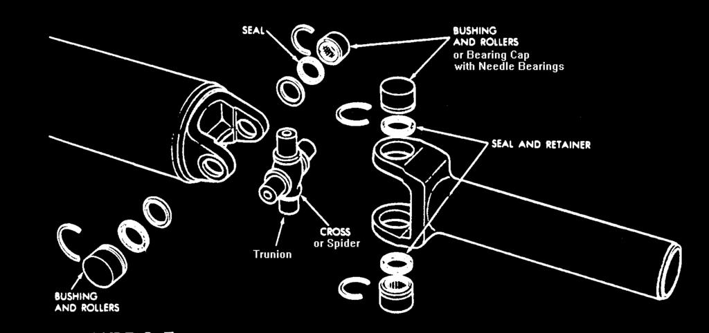
9 Universal Joints Can be called Cardan, Spicer, or Hooke joints Allow for angle changes between the drive shaft, the transmission output shaft, and the rear axle housing
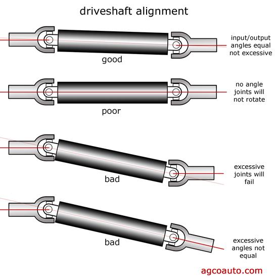
10 Universal Joint Characteristics U joints speed up and slow down twice per revolution Increased operating angle = Increased speed variation
11 Keep Operating Angle less than 4 Many say 3 is maximum

12 Transmission and Differential can be tilted to keep operating angles small
13 Transmission and Differential MUST be at the same angle to cancel speed variations (Vibration if wrong)
14
15

16 U Joints must be kept in Phase Small changes in phase = big vibration problem

17 When in Phase and same angle speed variations cancel from front to rear U Joint

18 Double Cardan U Joint
19 Double Cardan U Joints accept larger angles with no vibration. Do not recommend replacing individual pieces of the double cardan joint


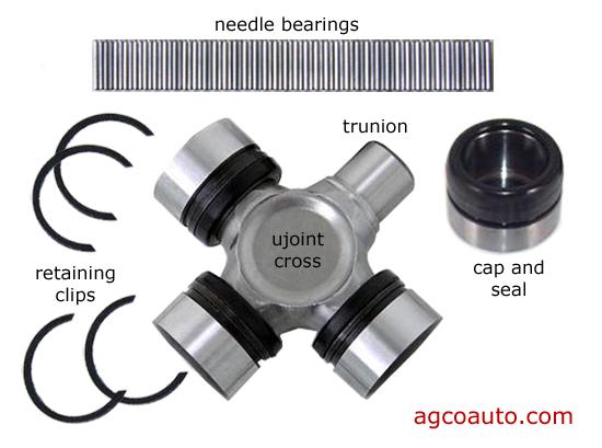
20 U Joints often fail and can easily be replaced Excellent article on why U joints fail
21
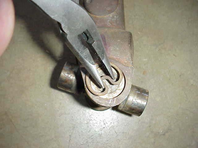
22 Tips for Disassembling a U Joint Index the joint s components before disassembly Remove all retaining rings before pressing on the spider Use a U joint tool kit, socket and vise, c clamp, or press to press the spider from the yoke
23 Index components before disassembly Might cause vibration if neglected
24
25 Remove all retaining rings
26
27

28 Easy way to ruin a driveshaft
29
30
31
32 U joint Service Avoid clamping hollow shaft in a vise to avoid denting shaft tube Do not hammer U Joint out of yoke. Use a vise or U joint press Clean yoke of burrs and pay extra attention to retaining ring grooves
33 U joint Service Use grease and caution to insure needle bearings stay in place on bearing cups If bearing caps will not fully install disassemble and realign roller bearings Insure that bearing retainers are fully seated


34 U joint Service Insure that U joint swivels freely after pressing into drive shaft Do not over tighten rear U joint U bolts
35 Most factory installed universal joints are sealed and don t require periodic lubrication After market replacement joints are equipped with a grease fitting and must be greased periodically
36 Types and Causes of Vibrations High speed vibrations Usually caused by driveshaft imbalance Vibrations during acceleration Usually caused by worn double Cardan joint Low speed vibrations Usually caused by improper operating angles
37 Clunking noise while accelerating from a dead stop Usually caused by worn or damaged U joint Squeaking noise Often caused by worn or poorly lubricated U joint
38 Check for Vibration Look for the obvious: worn U joints, dents in driveshaft, missing weights Reposition U joint flange (easy to try)
39 Check for Vibration Check Driveline Angles Front and rear angles should be within 1/2 Check Driveshaft Runout
40 Measuring Drive Shaft Runout Use a dial indicator Measure at the center and at both ends of shaft Should be less than.040 maximum runout Replace the shaft if runout is greater than allowed Be sure runout is not in pinion flange
41 Measuring Operating Angle Check vehicle ride height (full gas tank empty vehicle) Use inclinometer to measure U joint angles No more than 4 U joint angle Equal angle front and rear U joint
2007 Hummer H Driveline/Axle Propeller Shaft - H3. Fastener Tightening Specifications Specification Application
 2007 Driveline/Axle Propeller Shaft - H3 SPECIFICATIONS FASTENER TIGHTENING SPECIFICATIONS Fastener Tightening Specifications Specification Application Metric English Bolt - Front Propeller Shaft CV Joint
PROPELLER SHAFTS 16-1 PROPELLER SHAFTS CONTENTS
 Z PROPELLER SHAFTS 16-1 PROPELLER SHAFTS CONTENTS page GENERAL INFORMATION... 1 PROPELLER SHAFT REPLACEMENT... 7 SERVICE DIAGNOSIS/PROCEDURES... 3 page TORQUE SPECIFICATIONS... 14 UNIVERSAL JOINT REPLACEMENT...
2005 Mustang Workshop Manual
 SECTION 205-00: Driveline System General Information 2005 Mustang Workshop Manual GENERAL PROCEDURES Procedure revision date: 07/29/2004 Driveline Angle Inspection Printable View (122 KB) Special Tool(s)
PROPELLER SHAFT / / PROPELLER SHAFT GENERAL OVERVIEW AND OPERATION PROCESS 1. SPECIFICATION...
 3310-01/3310-00/3310-06 GENERAL 1. SPECIFICATION... 3 OVERVIEW AND OPERATION PROCESS 1. OVERVIEW... 2. COMPONENT LOCATOR... 3310-01 FRONT... 3310-06 REAR... 3310-00 DISASSEMBLY AND REASSEMBLY PROPELLER
Axles & Differentials
 ATASA 5 th Study Guide Chapter 39 Pages 1138 1172 60 Points Please Read The Summary Before We Begin Keeping in mind the Career Cluster of Transportation, Distribution & Logistics Ask yourself: What TDL
Manual Transmission/Driveline. Final Review
 Manual Transmission/Driveline Final Review 1. The Pressure Plate is a spring-loaded device that presses the clutch disc against the flywheel. 2. The clutch Release Mechanism allows the driver to disengage
PROPELLER SHAFT ASSEMBLY
 PR2 PROPELLER SHAFT COMPONENTS PR03I02 Front propeller shaft 80 (820, 59) 80 (820, 59) Front Propeller Shaft Transfer Front Differential 80 (820, 59) 80 (820, 59) No.2 Engine Under Cover Rear propeller
PR 3. PROPELLER SHAFT FRONT PROPELLER SHAFT ASSEMBLY (for 4WD) DISASSEMBLY
 DISASSEMBLY") OPELLER SHAFT FRONT OPELLER SHAFT ASSEMBLY (for 4WD) 3 C029928 DISASSEMBLY 1. INSPECT FRONT OPELLER SHAFT ASSEMBLY (a) Check that the propeller shaft is not damaged or deformed. If necessary, replace the
OPELLER SHAFT FRONT OPELLER SHAFT ASSEMBLY (for 4WD) 3 C029928 DISASSEMBLY 1. INSPECT FRONT OPELLER SHAFT ASSEMBLY (a) Check that the propeller shaft is not damaged or deformed. If necessary, replace the
DRIVE SHAFT ALIGNMENT
 DRIVE SHAFT ALIGNMENT 1988 Jeep Cherokee 1988 Drive Shafts Alignment DESCRIPTION Drive shafts are balanced, one-piece, tubular shafts with universal joints at each end. Number used in vehicle varies: one
Front Wheel Drive Notes
 Front Wheel Drive Notes Drive Axle Components Outer CV-joint Allows wheels to steer while axle is rotating Inner CV-joint Allows for suspension changes while axle is rotating Axle shaft Transmits power
TC Series Driveline. Table of Contents. TC Series Driveline
 TC Series Driveline Table of Contents Table of Contents...1 List of Figures...1 Safety...3 Warnings and Cautions...3 Inspection and Lubrication of Driveshaft...3 Inspection...3 Lubrication...5 Lubricants
UNIVERSAL JOINTS AND PROPELLER SHAFT
 Section XII UNIVERSAL JOINTS AND SERVICE BULLETIN REFERENCE NUMBER DATE SUBJECT CHANGES UNIV JOINTS AND 537 UNIVERSAL JOINTS AND DATA AND SPECIFICATIONS Propeller Shaft Number used C-67 C-68 C-69 C-70
DIFFERENTIAL AND DRIVELINE
 ZG DIFFERENTIAL AND DRIVELINE 3-1 DIFFERENTIAL AND DRIVELINE CONTENTS page 181 FBI AXLE... 15 194 RBI AXLE... 50 page 216 RBA AXLE... 87 PROPELLER SHAFTS... 1 PROPELLER SHAFTS INDEX page GENERAL INFORMATION
Front Suspension 2015 E-Series REMOVAL AND INSTALLATION Procedure revision date: 08/11/2014. Axle
 204-01 Front Suspension 2015 E-Series REMOVAL AND INSTALLATION Procedure revision date: 08/11/2014 Axle 1 N620604 Axle pivot nut 2 N806859 Axle pivot bolt 3 3007 LH/ 3006 RH LH/ 3006 RH Axle Removal NOTICE:
FRONT AXLE - 9 1/4 AA
 DR FRONT AXLE - 9 1/4 AA 3-45 FRONT AXLE - 9 1/4 AA TABLE OF CONTENTS page FRONT AXLE - 9 1/4 AA DESCRIPTION......................... 45 OPERATION........................... 45 DIAGNOSIS AND TESTING................
Driveline Service & Maintenance
 Section 3-3 Driveline Inspection Driveline Service & Maintenance To prevent serious eye injury, always wear eye protection gear when you perform vehicle maintenance or service. Do not service a drivehsaft
REMOVAL & INSTALLATION
 REMOVAL & INSTALLATION AXLE SHAFTS & BEARINGS Removal CAUTION: Failure to turn off air suspension power before raising vehicle may result in unexpected inflation or deflation of air springs. DO NOT reconnect
Yukon Gear & Axle D30, D44 & GM 8.5" Hardcore Locking Hub Installation Guide
 Yukon Gear & Axle D30, D44 & GM 8.5" Hardcore Locking Hub Installation Guide PLEASE READ COMPLETELY BEFORE INSTALLATION Application Guide: YHC70005 D30 & D44 30spl - YA WU-08 Spin Free - D30, 30 spline
PROPELLER SHAFT PR 3 COMPONENTS
 PR3 COMPONENTS PR4 PR5 REMOVAL (2WD) 1. DISCONNECT FLANGE FROM COMPANION FLANGE ON DIFFERENTIAL (a) Put matchmarks on the flanges. (b) Remove the four and nuts. 2. REMOVE CENTER SUPPORT BEARING FROM FRAME
M Ring and Pinion Installation
 !!! PLEASE READ ALL OF THE FOLLOWING INSTRUCTIONS CAREFULLY PRIOR TO INSTALLATION. Axle Shaft Removal (1994-2012 Mustang typical) STEP 1: STEP 2: Remove the 10 differential housing cover bolts and drain
Bearing and Seal Installation Tool T1 Clutch Assembly Stand X X X X Shift Handle Tool X X T Bearing Cup Driver X X
 Bravo Sterndrive Bravo Sterndrive Tool Application Chart Part No. Description Bravo One Bravo Two Bravo Three Blackhawk 11 24156 Hex Nut 12 34961 Washer 91 12427 Shift Cable Adjustment Tool 91 17256 Bearing
Installation Instructions for the Tera low range Dana 20 (LOW20)
") Installation Instructions for the Tera low range Dana 20 (LOW20) Tera Manufacturing, Inc. 5251 South Commerce Dr. Murray, Utah 84107 Phone/801.288.2585 Fax/801.288.2571 www.teraflex.biz Attention: Verify
Installation Instructions for the Tera low range Dana 20 (LOW20) Tera Manufacturing, Inc. 5251 South Commerce Dr. Murray, Utah 84107 Phone/801.288.2585 Fax/801.288.2571 www.teraflex.biz Attention: Verify
Service Manual. Spicer Drive Axle. AXSM-0400 September 2007
 Spicer Drive Axle Service Manual Spicer Drive Axle AXSM-0400 September 2007 This bulletin contains product improvement information. Dana Corporation is not commited or liable for canvassing existing product.
Steer Axles. Spicer. Service Manual. AXSM-0070 November Front Drive Steer Axle Model 60
 Spicer Steer Axles Service Manual AXSM-0070 November 2017 Front Drive Steer Axle Model 60 General Information The description and specifications contained in this service publication are current at the
REMOVAL & INSTALLATION
 REMOVAL & INSTALLATION CENTER BEARING SUPPORT ASSEMBLY Removal 1. With transmission in neutral and parking brake off, raise vehicle. Scribe alignment marks on all flange/yokes and slip joints to be disassembled
JK 8 Lug Front Locking Hub Conversion Kit
 JK 8 Lug Front Locking Hub Conversion Kit Kit #3034411 w/ Performance Rotors Kit #3034410 w/ Performance Slotted Rotors Kit #3034412 w/ Big Brake Kit Kit #3034413 w/ Big Brake Kit and Slotted Rotors Important
Driveshaft Runout and Balancing
 SECTION 205-00: Driveline System General Information 2009 Mustang Workshop Manual GENERAL PROCEDURES Procedure revision date: 07/18/2008 Driveshaft Runout and Balancing Special Tool(s) Dial Indicator Gauge
2007 Hummer H Driveline/Axle Wheel Drive Shafts - H3. Fastener Tightening Specifications Specification Application
 2007 Driveline/Axle Wheel Drive Shafts - H3 SPECIFICATIONS FASTENER TIGHTENING SPECIFICATIONS Fastener Tightening Specifications Specification Application Metric English Front Wheel Drive Shaft Nut 260
Steering Gearbox Disassembly
 Steering Gearbox Disassembly Steering Rack Disassembly 5. Unbend the lock washer. Before disassembling the gearbox, wash it off with solvent and a brush. Do not dip seals and O-rings in solvent. 1. Remove
TO INDEX DIFFERENTIAL FRONT DIFFERENTIAL CARRIER OIL SEAL (4WD) FRONT DIFFERENTIAL CARRIER ASSEMBLY (4WD) REAR DIFFERENTIAL CARRIER OIL SEAL
 FRONT DIFFERENTIAL CARRIER ASSEMBLY (4WD) REAR DIFFERENTIAL CARRIER OIL SEAL") TO INDEX DRIVE LINE / AXLE DIFFERENTIAL DIFFERENTIAL SYSTEM PRECAUTIONS.............................................. OPERATION CHECK......................................... PROBLEM SYMPTOMS TABLE.................................
TO INDEX DRIVE LINE / AXLE DIFFERENTIAL DIFFERENTIAL SYSTEM PRECAUTIONS.............................................. OPERATION CHECK......................................... PROBLEM SYMPTOMS TABLE.................................
PROPELLER SHAFT & DIFFERENTIAL CARRIER SECTIONPD CONTENTS
 PROPELLER SHAFT & DIFFERENTIAL CARRIER SECTIONPD CONTENTS PREPARATION...2 PROPELLER SHAFT...5 On-Vehicle Service...6 Removal and Installation...7 Inspection...7 Disassembly...7 Assembly...8 ON-VEHICLE
PROPELLER SHAFT & DIFFERENTIAL CARRIER SECTIONPD CONTENTS IDX. PROPELLER SHAFT...3 Preparation...3 C200. REAR FINAL DRIVE...40 Preparation...
 PROPELLER SHAFT & DIFFERENTIAL CARRIER SECTIONPD GI MA EM LC EC CONTENTS FE PROPELLER SHAFT...3 Preparation...3 SPECIAL SERVICE TOOLS...3 Noise, Vibration and Harshness (NVH) Troubleshooting...4 NVH TROUBLESHOOTING
Maintenance Information
 80234313 Edition 1 June 2006 Air Grinder, Die Grinder, Sander and Belt Sander Series G1 (Angle) Maintenance Information Save These Instructions WARNING Always wear eye protection when operating or performing
If it exceeds the maximum specification, replace the propeller shaft.
 If it exceeds the maximum specification, replace the propeller shaft. Maximum runout o 0.4 mm {0.016 in} 2. Inspect the play and rotation of the joint by turning the universal joint in the directions shown
MAINTENANCE MANUAL DP-265
 MAINTENANCE MANUAL DP-265 Drive Gears Sisu Axles, Inc. Autotehtaantie 1 P.O. Box 189 FIN-13101 Hämeenlinna Finland Phone int + 358 204 55 2999 Fax int + 358 204 55 2900 DP265DG.PDF (2/2003) k Table of
Spicer Driveshafts. Service Manual. DSSM3264 September 2007
 Spicer Driveshafts Service Manual DSSM3264 September 2007 Table of Contents Safety...................... 1 General Safety.......................... 1 Component Safety...................... 2 Driveline...........................
SUSPENSION 2-1 SUSPENSION CONTENTS
 DN SUSPENSION 2-1 SUSPENSION CONTENTS page ALIGNMENT... 1 FRONT SUSPENSION... 5 page REAR SUSPENSION... 13 ALIGNMENT INDEX page GENERAL INFORMATION WHEEL ALIGNMENT... 1 DIAGNOSIS AND TESTING PRE-ALIGNMENT
TECHNICAL MANUAL ORGANIZATIONAL, DIRECT SUPPORT, AND GENERAL SUPPORT MAINTENANCE MANUAL (INCLUDING REPAIR PARTS AND SPECIAL TOOLS LIST) FOR
 FOR") TM 5-4210-227-24&P-5 TECHNICAL MANUAL ORGANIZATIONAL, DIRECT SUPPORT, AND GENERAL SUPPORT MAINTENANCE MANUAL (INCLUDING REPAIR PARTS AND SPECIAL TOOLS LIST) FOR 85' AERIAL LADDER FIRE FIGHTING TRUCK NSN
TM 5-4210-227-24&P-5 TECHNICAL MANUAL ORGANIZATIONAL, DIRECT SUPPORT, AND GENERAL SUPPORT MAINTENANCE MANUAL (INCLUDING REPAIR PARTS AND SPECIAL TOOLS LIST) FOR 85' AERIAL LADDER FIRE FIGHTING TRUCK NSN
FRONT AXLE AND SUSPENSION FA 1
 FRONT AXLE AND SUSPENSION FA1 FRONT AXLE AND SUSPENSION FA2 FRONT AXLE AND SUSPENSION Troubleshooting TROUBLESHOOTING Problem Possible cause Remedy Page Wanders/pulls Tires worn or improperly inflated
Front Axle Pinion Seal Replacement
 Front Axle Pinion Seal Replacement by Flopster843 10 Apr 2016 The AAM 925 axle used on the front of Dodge Ram trucks is a decent unit, but it does have its flaws. This axle lacks lockout hubs on the front
Installation Instructions
 Suzuki Samurai 26 Spline Lockright Locker w/o Couplers (SKU# SAX-1510) Installation Instructions Suggested Tools: CAUTION: Safety glasses should be worn at all times when working with vehicles and related
Advanced Auto Tech. ASE A 3 Test Preparation Clutch & Drive Line Service
 Advanced Auto Tech ASE A 3 Test Preparation Clutch & Drive Line Service The clutch and the drive line both have their own unique symptoms and noises, separate from the transmissions used to change torque
Drive/Propeller Shaft: Service and Repair
 2001 Lexus IS 300 L6-3.0L (2JZ-GE) Page 1 Drive/Propeller Shaft: Service and Repair 2001 Lexus IS 300 L6-3.0L (2JZ-GE) Page 2 REMOVAL 1. REMOVE NO. 1 AND NO. 2 ENGINE UNDER COVERS 2. REMOVE LH FRONT FLOOR
1. General Description
 1. General Description A: SPECIFICATION 1. MANUAL TRANSMISSION AND FRONT DIFFERENTIAL Type Transmission gear ratio Front reduction gear Rear reduction gear Front differential Center differential Final
Suspension Upgrade System RS66152 (Upper Adjustable Control Arms)
") 89152 Rev B Suspension Upgrade System RS66152 (Upper Adjustable Control Arms) Fits 1997-2006 Jeep Wrangler (TJ / LJ). 89152 Rev B READ ALL INSTRUCTIONS THOROUGHLY FROM START TO FINISH BEFORE BEGINNING
89152 Rev B Suspension Upgrade System RS66152 (Upper Adjustable Control Arms) Fits 1997-2006 Jeep Wrangler (TJ / LJ). 89152 Rev B READ ALL INSTRUCTIONS THOROUGHLY FROM START TO FINISH BEFORE BEGINNING
DISASSEMBLY AND ASSEMBLY
 205-03-1 Front Drive Axle/Differential Ford 8.8-Inch Ring Gear 205-03-1 DISASSEMBLY AND ASSEMBLY Axle Front Drive Special Tool(s) 2-Jaw Puller 205-D072 (D97L-4221-A) Special Tool(s) Carrier Bearing Replacer
Ford 9 XD Aussie-Locker Install Instructions.
 Ford 9 XD-45831 Aussie-Locker Install Instructions. Before the install check the following. 1. Must be 31 spline 4-pinion carrier. 2. Must be an open carrier not a limited slip. 3. Refer to Ford or vehicle
CONTENTS
 PROPELLER SHAFT - ALL SERIES 4A- 1 PROPELLER SHAFT ALL SERSES CONTENTS DESCRIPTION AND OPERATION: Description of Propeller Shaft 4A- 1 DIAGNOSIS: Propeller Shaft Trouble Diagnosis 4A- 2 MAINTENANCE AND
Maintenance Information
 80234313 Edition 2 May 2014 Air Grinder, Die Grinder, Sander and Belt Sander Series G1 (Angle) Maintenance Information Save These Instructions Product Safety Information WARNING Failure to observe the
No-Slip Traction System
 INSTALLATION GUIDE TM No-Slip Traction System Installation Guide Contents Page Open Differential Part Identification & Terminology... 2 Powertrax No-Slip Differential Exploded View... 3 Vehicle Preparation
SUZUKI SQ 416/420/625 M.Y TRANSMISSION SERVICE MANUAL - MANUAL - AUTOMATIC - TRANSFER - DIFFERENTIALS
 SUZUKI SQ 416/420/625 M.Y 1998-2005 TRANSMISSION SERVICE MANUAL - MANUAL - AUTOMATIC - TRANSFER - DIFFERENTIALS WARNING/CAUTION/NOTE IMPORTANT Please read this manual and follow its instructions carefully.
Our goal is to make the install a breeze. Please read the entire guide before beginning.
 www.airkewld.com Page 1 of 6 IRS Axle Kit Install IRS Axle Kit Install Our goal is to make the install a breeze. Please read the entire guide before beginning. KITS SHOULD INCLUDE 2 - Control-arm mounting
Rear Axle Single-Reduction Carrier
 Revised 08-0 Rear Axle Single-Reduction Carrier Model MS-3 Maintenance Manual MM-030 Service Notes Service Notes Notes About This Manual This manual provides instructions for Meritor s model MS-3 single-reduction
SECTION 17 SUSPENSION CONTENTS FRONT SUSPENSION REAR SUSPENSION MAINTENANCE SERVICES
 SECTION 17 SUSPENSION CONTENTS 17-1. FRONT SUSPENSION...................................... 17-2 17-2. REAR SUSPENSION...................................... 17-15 17-3. MAINTENANCE SERVICES................................
REAR AXLE GROUP CONTENTS GENERAL DESCRIPTION DRIVE SHAFT ASSEMBLY REAR AXLE DIAGNOSIS
 27-1 GROUP 27 CONTENTS GENERAL DESCRIPTION 27-2 DIAGNOSIS 27-2 INTRODUCTION 27-2 TROUBLESHOOTING STRATEGY 27-2 SYMPTOM CHART 27-3 SYMPTOM PROCEDURES 27-3 SPECIAL TOOLS 27-8 ON-VEHICLE SERVICE 27-12 TOTAL
PERFORMANCE DRIVESHAFT TECH
 PERFORMANCE DRIVESHAFT TECH A properly selected and set up driveshaft can safely and smoothly deliver all of a performance engine s horsepower and torque to the rear wheels, while the wrong driveshaft
Service Bulletin Trucks
 Volvo Trucks rth America, Inc. Greensboro, NC USA This Service Bulletin replaces Service Bulletin 084 01, Special Tools, Group 4 (11.2003), Publication no. PV776 TSP 20 000363. Service Bulletin Trucks
SUSPENSION 2-1 SUSPENSION TABLE OF CONTENTS
 DN SUSPENSION 2-1 SUSPENSION TABLE OF CONTENTS page ALIGNMENT... 1 FRONT SUSPENSION - 4x2... 6 page FRONT SUSPENSION - 4x4... 14 REAR SUSPENSION... 23 ALIGNMENT TABLE OF CONTENTS page AND OPERATION WHEEL
ASE Practice Test A3 Manual Drive Train
 Clutch Diagnosis and Repair ASE Practice Test A3 Manual Drive Train 1) Which of the following are the three critical clutch pedal measurements? a. Pedal height, apply pressure, and free play b. Pedal free
PROPELLER SHAFT SECTION CONTENTS D DRIVELINE/AXLE PR-1
 D DRIVELINE/AXLE A SECTION PROPELLER SHAFT B C PR CONTENTS E PREPARATION... 2 Special Service Tools... 2 NOISE, VIBRATION, AND HARSHNESS (NVH) TROUBLESHOOTING... 3 NVH Troubleshooting Chart... 3 ON-VEHICLE
CLUTCH CONTENTS SERVICE DIAGNOSIS. (a) Worn or damaged disc assembly. (b) Grease or oil on disc facings. (c) Improperly adjusted cover assembly.
 Worn or damaged disc assembly. (b) Grease or oil on disc facings. (c) Improperly adjusted cover assembly.") CLUTCH CONTENTS -GROUP 6 Page CLUTCH HOUSING ALIGNMENT... 6 CLUTCH PEDAL FREE PLAY 1 CLUTCH RELEASE BEARING 5 CLUTCH RELEASE FORK... 5 CLUTCH SERVICING 2 PILOT BUSHING CRANKSHAFT TO TRANSMISSION DRIVE
CLUTCH CONTENTS -GROUP 6 Page CLUTCH HOUSING ALIGNMENT... 6 CLUTCH PEDAL FREE PLAY 1 CLUTCH RELEASE BEARING 5 CLUTCH RELEASE FORK... 5 CLUTCH SERVICING 2 PILOT BUSHING CRANKSHAFT TO TRANSMISSION DRIVE
Purposes of a Drive Axle Assembly
 Differentials Purposes of a Drive Axle Assembly To transmit power from the drive shaft to the wheels To turn the power flow 90 degrees on RWD cars To allow the wheels to turn at different speeds while
IN-VEHICLE REPAIR. Differential Bearings. Rear Drive Axle/Differential Ford 7.5-Inch Ring Gear. Special Tool(s)
") 205-02A-1 IN-VEHICLE REPAIR Differential Bearings Special Tool(s) Protector, Drive Pinion Thread 205-460 Special Tool(s) Installer, Differential Shim 205-220 (T85L-4067-AH) 205-02A-1 2-Jaw Puller 205-D072
205-02A-1 IN-VEHICLE REPAIR Differential Bearings Special Tool(s) Protector, Drive Pinion Thread 205-460 Special Tool(s) Installer, Differential Shim 205-220 (T85L-4067-AH) 205-02A-1 2-Jaw Puller 205-D072
Automatic Belt Tensioners:
 Automatic Belt Tensioners: Why cars have them and where to get them Over 100 million vehicles use automatic belt tensioners. Tensioners, like any other part, don t last forever, and automotive technicians
DRIVE AXLE Nissan 240SX DESCRIPTION & OPERATION AXLE RATIO & IDENTIFICATION AXLE SHAFT & BEARING R & I DRIVE SHAFT R & I
 DRIVE AXLE 1990 Nissan 240SX 1990 DRIVE AXLES Rear Axle - R200 240SX, 300ZX DESCRIPTION & OPERATION The axle assembly is a hypoid type gear with integral carrier housing. The pinion bearing preload adjustment
Yukon Gear & Axle. D30, D44 & GM 8.5" Hardcore Locking Hub Installation Guide PLEASE READ COMPLETELY BEFORE INSTALLATION
 Yukon Gear & Axle D30, D44 & GM 8.5" Hardcore Locking Hub Installation Guide PLEASE READ COMPLETELY BEFORE INSTALLATION COPYRIGHT 2014 - Yukon Gear & Axle Application Guide: YHC70005 D30 & D44 30spl -
FRONT AXLE SECTION FAX CONTENTS DRIVELINE/AXLE FAX-1 SERVICE INFORMATION... 2
 DRIVELINE/AXLE SECTION FAX A FRONT AXLE B C FAX CONTENTS E SERVICE INFORMATION... 2 PRECAUTIONS... 2 Caution...2 PREPARATION... 3 Special Service Tool...3 Commercial Service Tool...3 NOISE, VIBRATION AND
Service Bulletin Trucks
 Volvo Trucks rth America, Inc. Greensboro, NC USA This Service Bulletin Replaces Service Bulletin 087 01 Special Tools, Group 7 (12.2004), Publication number PV776-20 020978. Service Bulletin Trucks Date
 Page 1 of 5 Section 05-03A: Axle, Front Drive, Dana Models 44 and 50 1996 Bronco/F-Series Workshop Manual REMOVAL AND INSTALLATION Procedure revision date: 06/19/2000 Spindle, RH and LH Shaft and Joint
'99-03 CHEVROLET/GMC IFS 4WD 6" SUSPENSION SYSTEM P/N INSTALLATION INSTRUCTIONS
 1/16/04 '99-03 CHEVROLET/GMC IFS 4WD 6" SUSPENSION SYSTEM P/N. 10-41099 INSTALLATION INSTRUCTIONS NOTE: Each Lift Kit and options to Lift Kits are packaged separately. Therefore, installation procedures
FRONT AXLE SECTION CONTENTS D DRIVELINE/AXLE FAX-1 FAX
 FRONT AXLE D DRIVELINE/AXLE A SECTION FRONT AXLE B C FAX CONTENTS E PRECAUTIONS... 2 Caution... 2 PREPARATION... 3 Special Service Tools (SST)... 3 Commercial Service Tools... 3 NOISE, VIBRATION AND HARSHNESS
1. General Description
 General Description 1. General Description A: SPECIFICATION 1. PROPELLER SHAFT Propeller shaft type 3UJ Front propeller shaft Joint-to-joint length: L 1 mm (in) 633 (24.92) Rear propeller shaft Joint-to-Joint
1999 F-150/250 Workshop Manual
 Page 1 of 30 SECTION 205-03: Front Drive Axle/Differential Ford 8.8-Inch Ring Gear 1999 F-150/250 Workshop Manual DISASSEMBLY AND ASSEMBLY Procedure revision date: 01/08/2003 Axle Front Drive Special Tool(s)
Single Reduction Differential Carriers
 Revised 10-00 $2.50 Single Reduction Differential Carriers Maintenance Manual 5 Standard Carriers Including: Single Axles, Rear of Tandem Axles, Front Drive Steering Axles Excluding RS and RT Series (Rear
FRONT AXLE SECTION FAX CONTENTS TRANSMISSION & DRIVELINE FAX-1 SYMPTOM DIAGNOSIS... 2 ON-VEHICLE REPAIR... 7 PRECAUTION... 3
 TRANSMISSION & DRIVELINE SECTION FAX A FRONT AXLE B C FAX CONTENTS E SYMPTOM DIAGNOSIS... 2 NOISE, VIBRATION, AND HARSHNESS (NVH) TROUBLESHOOTING... 2 NVH Troubleshooting Chart...2 PRECAUTION... 3 PRECAUTIONS...
PROPELLER SHAFT AND UNIVERSAL JOINTS
 PROPELLER SHAFT AND UNIVERSAL JOINTS 16-1 GROUP 16 PROPELLER SHAFT AND UNIVERSAL JOINTS CONTENTS Page Page Ball and Trunnion Universal Joint. 4 Propeller Shaft (TY-1) 7 Center Bearing (TY-1) 8 Propeller
15.Main Shaft Assembly
 15.Main Shaft Assembly A: REMOVAL 1) Remove the manual transmission assembly from vehicle. 2) Remove the transfer case with extension case assembly.
I N S TA L L AT I O N G U I D E
 INSTALLATION GUIDE TM Installation Guide Contents Page Open Differential Part Identification & Terminology... 2 Powertrax No-Slip Differential Exploded View... 3 Vehicle Preparation for Installation (steps
Chevrolet Bar Kit
 1947-53 Chevrolet 3100 4-Bar Kit Congratulations on your purchase on what we believe is the finest rear suspension 4-bar kit available for 1947-53 Chevrolet pickups with stock frames. We have invested
1. General Description
 General Description 1. General Description A: SPECIFICATION 1. PROPELLER SHAFT Model All models Propeller shaft type EDJ Front propeller shaft Joint-to-joint length: L 1 mm (in) AT 735.5 (28.96) MT 675.5
Halfshaft. Special Tool(s) Differential Plug (T89P-4850-B) Differential Seal Protector Halfshaft Removal Tool
 Differential Plug (T89P-4850-B) Differential Seal Protector Halfshaft Removal Tool") Halfshaft Special Tool(s) Differential Plug 205-294 (T89P-4850-B) Differential Seal Protector 205-461 Halfshaft Removal Tool 205-475 Hub Remover/Replacer 204-069 (T81P-1104-C) Metric Hub Remover Adapter
Halfshaft Special Tool(s) Differential Plug 205-294 (T89P-4850-B) Differential Seal Protector 205-461 Halfshaft Removal Tool 205-475 Hub Remover/Replacer 204-069 (T81P-1104-C) Metric Hub Remover Adapter
Section II REAR AXLE CONTENTS
 REAR AXLE 1 Section II REAR AXLE CONTENTS Page Removal of Differential Carrier Assembly 5 Removing Drive Gear and Case Assembly 6 Drive Pinion and Bearing Disassembly 8 Pinion Bearing Pre-Load and Pinion
Single Rear Drive Axles, Rear-Rear Tandem Drive Axles and Front Drive Steer Axles Revised 02-18
 Maintenance Manual 5A Single-Reduction Differential Carriers Single Rear Drive Axles, Rear-Rear Tandem Drive Axles and Front Drive Steer Axles Revised 02-18 Service Notes About This Manual This manual
Rear Axle. Table of Contents
 Rear Axle Table of Contents Sub-Headings Safety 2 Warnings 2 Cautions 2 s 2 Introduction 2 Standard Single Reduction Carriers Without Differential Lock 5 Disassembly 6 Remove Differential Carrier from
DRIVE AXLES. Differentials & Axle Shafts - Corvette
 DESCRIPTION & OPERATION 1998-99 DRIVE AXLES Differentials & Axle Shafts - Corvette A Getrag 625 model differential is used on both the automatic and manual transmissions. Differential carrier and case
Maintenance Manual MM-0220 Single Reduction Differential Forward Carrier MD15. Issue November 2017
 Maintenance Manual MM-0220 Single Reduction Differential Forward Carrier MD15 Issue November 2017 Service Notes Before You Begin This publication provides installation and maintenance procedures for the
UOW Series Repair Manual UOW-11 & UOW-T60 Series
 UOW Series Repair Manual UOW-11 & UOW-T60 Series 100000 SE Pine St., Portland, OR 97216 800-852-1368 503-254-6600 www.aimco-global.com Contents Page 1. Tools Needed for Repair 2 2. Disassembly and Reassembly
Slip Yoke Eliminator Kit For NP231 Part Number 52231
 Slip Yoke Eliminator Kit For NP231 Part Number 52231 KIT CONTAINS: Rear Output Housing w/ plug Rear Output Seal Main Output Shaft Snap Ring for Speedometer Gear-QTY: 2 Snap Ring for Mode Gear Rear Output
PROPELLER SHAFT PR 1
 PR1 PR2 PREPARATION PREPARATION SST (SPECIAL SERVICE TOOLS) 0932520010 Transmission Oil Plug 2JZGE M/T 0932540010 Transmission Oil Plug 2JZGE A/T 0933000021 Companion Flange Holding Tool 0933050010 Propeller
AUT 231 (A3) MANUAL TRANSMISSION/TRANSAXLE AND DRIVETRAIN
 MANUAL TRANSMISSION/TRANSAXLE AND DRIVETRAIN") AUT 231 (A3) MANUAL TRANSMISSION/TRANSAXLE AND DRIVETRAIN COURSE DESCRIPTION: Prerequisites: TRN 120 Corequisites: None This course covers the operation, diagnosis, and repair of manual transmissions/transaxles,
AUT 231 (A3) MANUAL TRANSMISSION/TRANSAXLE AND DRIVETRAIN COURSE DESCRIPTION: Prerequisites: TRN 120 Corequisites: None This course covers the operation, diagnosis, and repair of manual transmissions/transaxles,
Eaton. Repair Information. Model and Piston Motors Fixed Displacement, Valve Plate Design. Medium Duty Piston Pump NO.
 Eaton Medium Duty Piston Pump NO. 7-141 Repair Information Model 74318 and 74348 Piston Motors Fixed Displacement, Valve Plate Design Parts Drawing 8 1 2 3 4 5 6 5 4 7 22 23 Rear or Opposite side Porting
DF 47 DIFFERENTIAL REAR DIFFERENTIAL CARRIER ASSEMBLY REMOVAL
 47 REMOVAL 1. DISCONNECT CABLE FROM NEGATIVE BATTERY TERMINAL 2. REMOVE REAR WHEEL 3. DRAIN BRAKE FLUID Immediately wash off any brake fluid that comes into contact with any painted surfaces. 4. DRAIN
Output Shaft Assembly COMPONENTS
 MT140 Component Parts (Output Shaft Assembly Output Shaft Assembly COMPONENTS DISASSEMBLY OF OUTPUT SHAFT ASSEMBLY 1. REMOVE SLEEVE FROM OUTPUT SHAFT Using SST, remove the sleeve from the output shaft.
Overhaul Special Tools Required
 1 of 31 Overhaul - Special Tools Required - Cylinder end seal remover attachment, 07NAD-SR3020A - Pilot collar, 07GAF-PH70100 - Valve seal ring sizing tool, 07NAG-SR3090A - Ball joint boot clip guide,
INSTALLATION INSTRUCTIONS Cherokee / Grand Cherokee 3" Value Flex Lifts
 INSTALLATION INSTRUCTIONS Cherokee / Grand Cherokee 3" Value Flex Lifts Before beginning the installation, read these instructions and the enclosed driver s WARNING NOTICE thoroughly and completely. Also
Parts List. 2 Top Steel Re-Enforce Plates /16 Rear Panhard Bar 2 TCI All American Coil- Over s. Bracket
 1962-1967 Chevy Nova 4-Link Installation Instructions 1-866-925-1101 www.totalcostinvolved.com Read and understand these instructions before starting any work! USE THE PARTS LIST BELOW TO MAKE SURE YOUR
Spicer Driveshaft Components Failure Analysis Guide
 Spicer Driveshaft Components Failure Analysis Guide Learn how to identify failed driveshaft components. Preventive Maintenance Driveshaft inspection should be performed as part of your regular maintenance.
COMPONENTS REAR DIFFERENTIAL COMPONENTS
 COMPONENTS REAR DIFFERENTIAL COMPONENTS REMOVAL 1. Drain the differential gear oil. 2. Remove the rear disk brake. 3. Remove the parking brake and cable. 4. Remove the stabilizer bar. 5. Pull out the
LIMITED SLIP DIFFERENTIAL INSTALLATION
 Installation of the limited slip gear can be done with axle out of car or with car lifted to gain access from underneath. Refer to repair manual for proper lifting instructions if car is to be lifted.
13. CRANKCASE/CRANKSHAFT/BALANCER/PISTON/CYLINDER
 13. CRANKCASE/CRANKSHAFT/BALANCER/PISTON/CYLINDER COMPONENT LOCATION 13-2 SERVICE INFORMATION 13-3 TROUBLESHOOTING 13-4 CRANKCASE SEPARATION 13-5 CRANKSHAFT 13-7 MAIN JOURNAL BEARING 13-9 CRANKPIN BEARING