EMC COMPLIANCE EN AS/NZS 1044 EN AS/NZS EN AS/NZS
|
|
|
- Dominick Anthony
- 6 years ago
- Views:
Transcription
1 )3:0
2 Contents ii EMC COMPLIANCE This product is approved for use in Europe and Australia/New Zealand and conforms to the following standards European Norms Australian / New Zealand Standards EN AS/NZS 1044 EN AS/NZS EN AS/NZS To ensure continued compliance with EMC Directive 89/336 and the Australian Radiocommunications Act 1992, use only high quality data cables with continuous shield, and connectors with conductive backshells. Examples of such cables are: DMX: Belden % Aluminium foil screen, 65% Copper braid. JANDS ELECTRONICS PTY LTD 1997 All rights reserved DISCLAIMER Information contained in this manual is subject to change without notice and does not represent a commitment on the part of the vendor. JANDS ELECTRONICS PTY LTD shall not be liable for any loss or damage whatsoever arising from the use of information or any error contained in this manual. It is recommended that all service and repairs on this product be carried out by JANDS ELECTRONICS PTY LTD or its authorised service agents. JANDS GP Series dimmers must only be used for the purpose they were intended by the manufacturer and in conjunction with this operating manual. JANDS ELECTRONICS PTY LTD cannot accept any liability whatsoever for any loss or damage caused by service, maintenance or repair by unauthorised personnel, or by use other than that intended by the manufacturer. Disconnect mains power when not in use. Manufactured in Australia by: JANDS ELECTRONICS PTY LTD ACN Kent Rd Locked Bag 15 MASCOT NSW 2020 Sydney Australia PHONE: FAX: jandsinfo@jands.com.au
3 Contents Table of Contents iii Table of Contents 1.0 Introduction 2.0 Equipment Description 2.1 Front panel layout Getting Started 3.1 Connecting power Three phase star wiring Three phase delta wiring Single phase wiring Setting the mains frequency Powering up Connecting loads Connecting DMX-512 input DMX Termination Adjusting the Preheat Power-up sequence Dimmer Operation 4.1 Operating modes DMX mode Test mode Status LED
4 Contents 5.0 Fault Diagnosis iv 5.1 Output protection Output faults DMX faults Phase fault indication Overheating Over-voltage Fault finding guide Installation 6.1 Dimmer Ventilation Wall Mounting Dimmers - In Racks Wall Mounting Dimmers - Flush to Wall Wall Mounting Dimmers - Straddling Cable Trays Wall Mounting Dimmers - Conduit Cable Entry Wall Mounting Dimmers - Hung from Bar Hooks Wall Mounting Dimmers - Patch Lead Option Mounting the dimmer to the bracket Maintenance 8.0 Technical Data and Specifications 8.1 DMX connector pin-outs DMX bank allocations Mains wiring colour codes
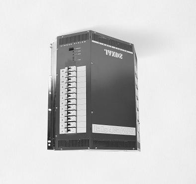
5 Introduction Introduction The JANDS FP12WM is a high quality, rugged, 12 channel, 2.4kVA per channel (10A/240V) dimmer rack specifically designed for contracting / theatre applications. A separate wall bracket simplifies the installation process. It allows cabling to be routed to the dimmer location prior to the installation of the actual dimmer units, providing the contractor with the ability to fit off the dimmers when the site is secure. As an option, a 24 way patch panel kit is available which, when combined with the extended wall mounting bracket, provides the end user with an economical and compact dimmer rack/patch Features 12 x 2.4KW dimming channels DMX-512 digital control protocol DMX terminating switch Suitable for permanent installations Soft turn on characteristic Low acoustic/electrical noise Jands Ferrodip TM chokes Three mains phase indicator LEDs Built in test facilities Dimmer curve set for linear relationship between the control input and output power Compensation for fluctuations in the mains supply voltage and minimises the effect of superimposed control tones, ensuring a constant light output and increased lamp life May be rack mounted, attached to a wall by means of supplied mounting brackets, or rigged using hook clamps Microprocessor control Single, three phase star, or three phase delta operation Over-temperature cutout Pre-heat facility Dimmer will hold last DMX value should control data be interrupted 50/60Hz operation CE and CTick approved
6 Equipment Description Equipment Description
7 Equipment Description Front panel layout Refer to Fig 2.1 (opposite) for a description of the front panel controls. 1. Channel output sockets: The twelve output sockets are each rated at 10 amps. 2. Channel output circuit breaker: If a circuit breaker trips during use ensure the fault has been cleared before resetting. 3. Bank select switches: These switches select the DMX start bank and the Test functions. 4. DMX SIGNAL LED: A green LED indicates the presence of DMX signals. If there is no DMX signal, the LED will flash at a rate of approximately 2 seconds on/ 2 seconds off. 5. STATUS LED: A red LED flashes in the presence of a fault. In normal operation this LED should be off. 6. PHASE LEDs: Three green LEDs (one for each phase) indicate that the three phase mains supply is available.
8 Getting Started Getting Started The FP12WM would normally be wall mounted before any wiring is terminated. Refer to section 6.0 Installation for details. 3.1 Connecting power The FP12WM dimmer is supplied with a 6 way terminal block for the connection of incoming mains power. The FP12WM can be powered from either: Three Phase star (four wire plus earth) Three phase delta (three wire plus earth) Single phase (three wire pairs plus earth) In each case the supply must be protected by a suitable circuit breaker. Refer to the specification table for the upstream circuit breaker rating Three phase star wiring This is the normal three phase power connection. The incoming power cable is terminated within the dimmer at a six-way terminal block and an earthing stud. The sixway terminal block has three poles for the three live mains phases (labelled A1, A2, A3), and three poles for the mains neutral (N1, N2, N3). The three neutral poles are bridged with a copper link, with the mains neutral connected to terminal N2. copper link Neutral Phase A Phase B Phase C Figure 3.1: Three phase star wiring
9 Getting Started Three phase delta wiring WARNING This connection is ILLEGAL in Australia, Europe and the U.K. This connection renders the output sockets' neutral pins LIVE. Note that the maximum phase to phase voltage with a delta power source is less than for a normal Star connection refer to the specifications for details. The available venue mains supply in some countries may be in the form of three phases with no neutral connection. In this case the bridge between the three neutral terminal poles (N1, N2, N3) must be removed and the incoming mains wiring connected as follows: The first incoming active is connected to terminals A1 and N3. The second incoming active is connected to terminals A2 and N1. The third incoming active is connected to terminals A3 and N2. N1 N2 N3 A1 A2 A3 Phase A Phase B Phase C Figure 3.2: Three phase delta wiring
10 Getting Started Single phase wiring The dimmers may be configured for single phase operation where three phase mains supply is unavailable. The dimmer must be supplied with three same-phase actives and three neutrals. The three active lines must each be individually circuit breaker protected. The three neutral conductors must each be rated at the same current as the actives. The earth conductor should be similarly rated. The bridge between the three neutral terminal poles (N1, N2, N3) must be removed before the three incoming neutral lines are connected. Although it is possible to supply the dimmer with one large single phase feed, the dimmer s breakers are not rated to clear faults if the supply is protected at currents of over 50 amps. N1 N2 N3 A1 A2 A3 N A N A N A Circuit A Circuit B Circuit C Figure 3.3: Single phase wiring
11 Getting Started Setting the mains frequency The FP12WM can be configured to run from either 50Hz or 60Hz mains power - as supplied from the factory it is configured for 50Hz. To change the dimmer to 60Hz, change the three jumpers to 60Hz as per Figure Figure 3.4: 60Hz jumper locations 3.3 Powering up Turn on the power and check that the three PHASE indicator LEDs are on before connecting any loads. If the PHASE LEDs indicate a fault condition (see section 5.4), power down and remedy the fault before trying again. If all is well, power down and connect loads. 3.4 Connecting loads The standard output connectors are either twelve Clipsal 415P 10 amp sockets, twentyfour Weiland GST18 sockets, or terminal strip (export models may differ from these configurations). Ensure any plugs are pushed firmly into their sockets and/or all screw terminals are tight. The FP12WM will drive most incandescent loads as well as hotspots, fans, and dimmable fluorescent tubes. The load should be greater than the specified minimum. 3.5 Connecting DMX-512 input The dimmer input signal should conform to the USITT DMX specification. The DMX input connects to the terminal strip on the main circuit board labelled DMX IN. The DMX signal may be daisy-chained to the next dimmer via the terminal strip labelled LOOP. The green DMX IN LED indicates the presence of DMX signals. Refer to Section 8.2 for DMX connections. 3.6 DMX Termination In any DMX-512 system the signal should be terminated at the last dimmer receiver in the chain, and the FP12WM can provide this function. To terminate the DMX signal, remove the front panel and locate the jumpers labelled Link Setting at the top of the main circuit board. As supplied from the factory the jumpers will be set to Thru, where
12 Getting Started 3-5 no DMX termination is applied. Shift the two jumpers to the Term position to terminate the DMX control signal. Note that in this position no signal is present at the DMX Thru terminals. DMX IN DMX THRU LINK SETTING Figure 3.5: DMX termination jumper position 3.7 Adjusting the Preheat The FP12WM incorporates a global preheat facility that allows all channels to be driven at a low level when the control input is off. This feature can extend the life of the lamps and minimise nuisance tripping of circuit breakers. In practice the preheat trimpot on the main circuit board is adjusted until the connected loads show a barely perceptible dull glow. 3.8 Power-up sequence When powering up lighting systems, the following sequence should be used: 1. First the control desk; 2. Then any softpatches and/or DMX receivers; 3. Finally the dimmers, preferably one at a time starting from the first dimmer rack in the DMX loop. This procedure minimises the risk of producing the lighting equivalent of an audio thump and prevents damage to lamps, dimmers, and other controlled devices. Use the reverse procedure when powering down.
13 Dimmer Operation Dimmer Operation This section assumes the dimmer has been correctly connected to three phase power and a source of DMX-512 control signal. 4.1 Operating modes The FP12WM has two operating modes: 1. DMX mode: the dimmer is controlled from an external DMX-512 control console, 2. Test mode: the dimmer is controlled by the internal microprocessor DMX mode In this mode, the DMX Bank Select switches are used to select which bank of 12 channels from the 43 possible DMX-512 banks will control the FP12WM. See Table 4.1 (below) for a list of banks and their corresponding Channels. Decide which bank of channels is required, and rotate the selector switches to the desired setting. For example, if DMX Channels 25 to 36 are desired (ie. bank 3), set selectors to 03. FP12WM Channel #1 is now DMX Channel #25. A FP12WM with this setting ignores DMX Channels 1 to 24 and 37 to 512, and only decodes Channels 25 to 36 as it s dimmer information. Setting the Selectors to 00 puts the dimmer in a standby state, with all Channels driven to the preheat setting. Bank Channels Band Channels Band Channels Band Channels 00 Outputs at minimum Table Test mode DMX bank / Channel allocation In this mode, the FP12WM s internal controller is used to drive the dimmer channels. It is accessed by setting the Selector switches to banks between 44 and 99. No DMX control is necessary, but a control signal may be left connected if desired.
14 Dimmer Operation 4-2 This mode is split into two sections with individual Channel testing from banks 44 to 59 and group channel testing from banks 60 to 99. The first section is not level controllable and each channel is driven to full. Refer to Table 4.2. Selector Channel Output Switches Under Test Level 44 Channel 1 Full 45 Channel 2 Full 46 Channel 3 Full 47 Channel 4 Full 48 Channel 5 Full 49 Channel 6 Full 50 Channel 7 Full 51 Channel 8 Full 52 Channel 9 Full 53 Channel 10 Full 54 Channel 11 Full 55 Channel 12 Full Step Chase Full Table 4.2 TEST MODE Individual Channel Selection The second section is level controllable, the level being set by the right hand Selector switch. The left-hand Selector switch changes the grouping. Refer to Table 4.3. Selector Switches Channel Channel Left Right Grouping Level Channels 1-4 ON (Phase A) Channels 5-8 ON (Phase B) Channels 9-12 ON (Phase C) Channels 1-12 ON 0-9 Table 4.3 TEST MODE Group Selection 4.2 Status LED The Status LED is used to indicate fault conditions. In normal operation this LED should not illuminate. When active this LED will either be flashing or on continuously. 1. When the LED is flashing an over-temperature or over-voltage condition is present, and the dimmer outputs will be driven to the preheat level until the over-voltage or over-temperature condition is removed. 2. The status LED being on continuously indicates one or more of the following error conditions have occurred: Over-voltage
15 Dimmer Operation 4-3 Over-temperature Serial data errors Software failure The dimmer outputs are active while the Status LED is on continuously. If the Status LED is on it may be cleared by changing the setting of the bank select switches or by switching the dimmer off momentarily.
16 Fault Diagnosis Fault Diagnosis NOTE Contact your authorised JANDS Distributor for repairs or servicing. In Australia refer all repairs to an authorised JANDS service agent or return the faulty unit in suitable packaging to: JANDS ELECTRONICS Service Dept, 40 Kent Rd Mascot NSW 2020 Sydney Australia 5.1 Output protection Output protection consists of a circuit breaker on each channel. These are designed to pass the rated current, but will disconnect the output circuit for any overload condition; the larger the overload, the quicker the disconnection. The purpose of the circuit breaker is to protect the dimmer s output devices from shortcircuit loads and faulty wiring looms, and save on expensive repairs. At the same time, the tripped circuit breaker indicates to the operator a load fault that requires immediate attention. 5.2 Output faults If a short-circuit lamp or output cable is plugged into the dimmer, the circuit breaker will trip to disconnect the fault from the dimmer. In nearly all circumstances, this is quick enough to prevent damage to the output devices. In some circumstances however, a triac failure may be experienced, although these devices are usually quite reliable and robust. If a triac does fail, it will either turn a channel on to full (triac short-circuit), or turn it off (triac open-circuit). If a triac fault should occur, that channel may be isolated by manually switching the circuit breaker off. 5.3 DMX faults The FP12WM dimmer features an Output Hold facility that remembers the last received DMX message. In the event of a cable being unplugged or severed, the FP12WM dimmer rack will continue to output the Held DMX levels until a new DMX message is provided. The DMX IN LED will flash slowly if the DMX signal is removed.
17 Fault Diagnosis Phase fault indication The three green PHASE LEDs will show when all three power input phases are present. WARNING IF ONE OR MORE PHASE LEDS IS OFF, IMMEDIATELY DISCONNECT POWER TO THE DIMMER AND CHECK THE MAINS SUPPLIES AND WIRING BEFORE RE-CONNECTING POWER TO THE DIMMER. 5.5 Overheating As the FP12WM is a convection-cooled dimmer, it is very important that adequate ventilation is provided when in use, particularly around the top and bottom vent slots. If the vent slots are blocked and/or the ambient air temperature is too high, the dimmer will shut down and the status LED will flash until the temperature is reduced. A FP12WM running normally at full power will get quite warm to the touch. In addition a mechanical cutout isolates the dimmer electronics if the internal temperature rises above the specified maximum. Refer to section 6.1 regarding FP12WM ventilation requirements. 5.6 Over-voltage The FP12WM incorporates an over voltage cutout that constantly monitors the incoming mains voltage. If the mains voltage rises above the specified maximum the dimmer will shut down and the status LED will flash until the over voltage condition is removed.
18 Fault Diagnosis Fault finding guide FAULT SYMPTOM POSSIBLE CAUSE REMEDY Circuit breaker trips when desk channel flashed to full or near full Circuit Breaker trips after prolonged operation Circuit breaker trips immediately when channel is driven One channel flickers when dimmed Same load flickers on another Channel Large incandescent load Excessive load Excessive load Lamp or wiring fault Output short Triac short DMX source problem Faulty dimmer channel Insufficient or very inductive load Use dimmer Preheat facility Reduce Channel loading Reduce Channel loading Check lamps and wiring Check lamps and wiring Factory service Softpatch another desk fader Service desk Factory service Connect 100W lamp in parallel Radio interference Faulty EMC filtering Factory service All Channels flicker when dimmed Signal LED flickers Status LED flashing Status LED on continuously Incorrect DMX protocol / wiring Mains control tones exceed limits Faulty DMX wiring/connections Faulty console Faulty dimmer rack Over-voltage Over-temperature Recent over-voltage Recent over-temperature DMX control errors Software failure Replace DMX source / wiring Contact factory Repair Repair Factory service Check mains connection/supply Improve dimmer cooling Check mains connection/supply Improve dimmer cooling Check DMX wiring, console Factory service
19 Installation Installation The FP12WM dimmers are designed for use in fixed installations - the dimmer is supplied with a wall-mounting bracket. This bracket enables the FP12WM to be mounted in one of the following arrangements: The dimmer may be mounted in a 19 inch equipment rack, using 11RU The dimmer may be mounted flush to a wall with the cabling coming through the wall The dimmer may be flown from a bar using a pair of standard hook clamps (not supplied) An optional extended mounting bracket allows the following mounting options: The dimmer may be mounted proud of a wall for use with surface cable conduit. The conduit may run either horizontally or vertically The dimmer may be mounted so to straddle a vertical cable tray up to 420mm wide and 75mm deep An optional patch kit allows an extended mounting bracket to be used as an output patch panel.
20 Installation Dimmer Ventilation The FP12WM dimmers are cooled by natural convection. The air intake is by slots at the bottom front, and exhausts through slots at the top and top-front. The FP12WM dimmers are intended for wall mounting in unenclosed spaces. Multiple dimmer arrays should be spaced at least 100mm apart vertically, and no more than three dimmers high, to avoid excessive heating of the top dimmer. Dimmers should be spaced at least 50mm horizontally. Dimmers should be mounted at least 300mm from the floor to avoid excessive ingress of dust and fluff, or as dictated by local building statutes. Dimmers must be mounted at least 150mm below ceilings or shelves for adequate ventilation. Mounting within unventilated cupboards is not recommended. If the dimmers are mounted within cupboards, allow at least 150mm above and below the dimmer, and at least 100mm at each side and the front of the dimmer. In addition, the cupboard must be vented with at least 400 cm 2 (eg 40cm x 10cm) per dimmer at the top and bottom of the cupboard. Additional venting area will serve to further reduce internal dimmer temperatures and will enhance the dimmer s reliability. CEILING >150 GP12WM GP12WM JANDS JANDS >100 GP12WM GP12WM JANDS JANDS >50 >300 FLOOR
21 Installation Wall Mounting Dimmers - In Racks Both the wall and the extended mounting bracket may be attached to standard 19" rack strips. The bracket is screwed to the rack strip using standard cage nuts and screws (not supplied). A rear blanking plate (supplied) is fastened inside the dimmer with five screws. Supply cable entry may be via a 32mm gland hole at the bottom right of the main chassis, or via one of two 32mm holes in the rear blanking plate. Unused 32mm holes should be covered with the blanking plugs provided. Attach the dimmer to the bracket as described in Section 6.8.
22 Installation Wall Mounting Dimmers - Flush to Wall Remove the cable access blanking piece of the wall mounting bracket by cutting the holding webs with shears. De-burr the metal. Feed any cables (supply, output, and control) through this cable access cutout, and place the bracket against the wall, orienting the bracket as indicated on the bracket. Mark and drill at least 4 fixing points, and attach the bracket to the wall. Attach the dimmer to the bracket as described in Section 6.8.
23 Installation Wall Mounting Dimmers - Straddling Cable Trays The optional extended mounting bracket will straddle cable trays up to 420mm wide and 75mm deep. Remove the top blanking piece by cutting the holding webs with shears, and remove the eight screws securing the bottom blanking piece. De-burr the metal. Position the bracket over the cable tray against the wall, orienting the bracket as indicated on the bracket. Mark and drill at least 4 fixing points, and attach the bracket to the wall. Feed any cables (supply, output, and control) through the cable access cutout. Attach the dimmer to the bracket as described in Section 6.8.
24 Installation Wall Mounting Dimmers - Conduit Cable Entry Use both the wall and optional extended mounting brackets to form an enclosure. Place the deep bracket over the shallow bracket, so that the tags in the back of the deep plate fit into the mating slots in the shallow bracket, noting the orientation marks on both pieces. Use four thread-cutting screws (supplied) at each side to screw the two pieces together, forming an 80mm deep enclosure. The enclosure formed has an assortment of holes to suit 25mm and 32mm (1" and 1-1/4") conduit end nuts on all four sides. Place the assembly against the wall at the desired location, and mark and drill holes for at least 4 fixing points. Mount the enclosure on the wall. Attach the dimmer to the bracket as described in Section 6.8.
25 Installation Wall Mounting Dimmers - Hung from Bar Hooks The FP12WM dimmers have two M10 captive nuts on the top face. These may be used to secure the dimmer using standard bar hooks (not supplied), allowing the dimmers to be flown from lighting trusses or catwalk rails. The bolts should not penetrate the top surface of the dimmer by more than 25mm. Additional holes at the top rear edge of the dimmers allow the dimmer chassis to be secured with safety cables. The dimmers are flown without using the wall or extended mounting brackets. A rear blanking plate (supplied) is fastened inside the dimmer with five screws. Supply cable entry may be via a 32mm gland hole at the bottom right of the main chassis, or via one of two 32mm holes in the rear blanking plate. Unused 32mm holes should be covered with the blanking plugs provided.
26 Installation Wall Mounting Dimmers - Patch Lead Option The wall-mount bracket system may include flying lead output patching. Two types of flying lead patch options are available: Twenty-four 3-pin Australian Clipsal 463 plugs Twenty-four 3-pin Wieland ST18 plugs Output cables up to 4mm 2 capacity are terminated at screw terminal blocks. These terminal blocks are supplied pre-wired to plugs on flying patch leads, which may then be patched to any desired dimmer outlet socket. To install: 1. Remove the bottom blanking plate from the optional extended bracket (eight screws). 2. Replace the bottom blanking plate with the pre-wired patch gland plate using the screws removed in step Fasten the deep bracket to the shallow bracket (see section 6.2.4). 4. Screw the terminal block plate to the shallow bracket (six screws). 5. Secure the assembly to the wall as described in section Connect the load wires to the terminal blocks. 7. Mount the dimmer as described in Section 6.8 and connect the supply and DMX-512 cables. OUTPUT CABLES PATCH CABLES
27 Installation Mounting the dimmer to the bracket Dimmers are attached to the pre-mounted brackets as follows: 1. Remove the dimmer s right-hand front panel (eight screws). 2. Hang the top edge of the dimmer on the two bracket tabs. These support the weight of the dimmer while allowing the bottom of the dimmer to pivot away from the bracket. 3. Feed any cables (mains supply, output or control) into the rear of the dimmer and terminate them as necessary. This may only be performed by a licensed electrician. 4. Latch the dimmer onto the bracket by lifting the dimmer a few millimetres and allowing the bottom two bracket tabs to engage. 5. Lock the dimmer in place with one M4 screw at the bottom right inside corner. 6. Re-attach the front panel
28 Maintenance Maintenance With care, the FP12WM dimmer will require little or no maintenance. WARNING DO NOT ALLOW THE ENTRY OF LIQUIDS OF ANY SORT INTO THE DIMMER CHASSIS. If the front panel requires cleaning, wipe with a mild detergent on a damp soft cloth. DO NOT spray liquids onto the front panel. DO NOT use solvents for cleaning the front panel.
29 Technical Data and Specifications Technical Data and Specifications PARAMETER FP12WM No. of Channels: 12 Input Power Requirements 3 phase Star: Input Power Requirements 3 phase Delta: Input Power Requirements Single Phase Maximum Power / Channel Minimum Power/Channel Maximum Dissipation 415 VAC 40A/phase protected at 50A/phase 240 VAC 40A/phase protected at 50A/phase Three 40A protected at 50A each 2.4 kw 25W <24 W/channel (<300 W total) Maximum Ambient Temp 40ºC Control Signal DMX Input DMX-512 (1990) Protocol Circuit board terminal strip Test Function Level Individual 100% Group 10% steps LED Indicators DMX IN, STATUS, Phases A, B, and C Output Protection 12 x 10 Amp circuit breaker Over temperature cutout Electronic: 83 o C rising, 78 o C falling Mechanical: 90 o C Over voltage cutout Average 290VAC Preheat adjustment 0-10% Size (mm) 482 (w) x 485 (h) x 130 (d) Weight 16 kg net
30 Technical Data and Specifications DMX connector pin-outs PIN No CONNECTION (DMX IN) CONNECTION (LOOP) 1 SHIELD SHIELD 2 IN- OUT- 3 IN+ OUT+ 8.2 DMX bank allocations BANK CHANNELS BANK CHANNELS 00 Preheat Only
31 Technical Data and Specifications Mains wiring colour codes Phase A Phase B Phase C Neutral Earth Red White Blue Black Green/Yellow
GP12 TECHNICAL MANUAL
 GP12 D i g i t a l l y C o n t r o l l e d D i m m e r R a c k TECHNICAL MANUAL Contents i Table of Contents Table of Contents... i 1.0 Introduction... 1-1 2.0 Equipment Description... 2-1 2.1 Front panel
JANDS DD-8. Technical Manual. Version 1.0
 JANDS DD-8 O p t o - I s o l a t e d D M X S p l i t t e r Technical Manual Version 1.0 EMC COMPLIANCE This product is approved for use in Europe and Australia/New Zealand and conforms to the following
JANDS DD-8. Operating Manual. Version 2.0
 JANDS DD-8 O p t o - I s o l a t e d D M X S p l i t t e r Operating Manual Version.0 JANDS DD-8 DMX SPLITTER EMC COMPLIANCE This product is approved for use in Europe and Australia/New Zealand and conforms
User Manual JS-ICON. 624 ARCH Dimmer Rack. JOHNSON SYSTEMS INC. Spring
 User Manual JS-ICON 624 ARCH Dimmer Rack JOHNSON SYSTEMS INC. Spring 2007 2002161 Table of Contents JS-ICON 624 DMX JS-ICON 624 CC 6-2.4kW Dimming Strip JS-ICON 624 ND 6-2.4kW Relay Strip Introduction...3
RE-PR3-E-86&105 3-Phase Panel Mount 86 and 105kW
 Page 1 of 6 3-Phase Panel Mount 86 and 105kW Features: Benefits: 0-10Vdc, 0-5Vdc, 4-20mA or manual via potentiometer control input Over temperature protection with auto reset Enclosed panel mounting Efficient
ACC Series Power Conditioner OPERATION & INSTALLATION MANUAL
 ACC Series Power Conditioner OPERATION & INSTALLATION MANUAL PHASETEC digital power conditioners are designed to safely operate electrical equipment in the harshest power quality environments. With a wide
PRO Dimmer INSTRUCTION MANUAL
 PRO Dimmer 2,000 WATT PRECISION AC DIMMER INSTRUCTION MANUAL McIntire Enterprises, Inc. 12986 Mapleleaf Ct. NE. Aurora, OR 97002-8418 Phone: 503-678-6236 www.magicgadgets.com benchtech@magicgadgets.com
SAVE THESE INSTRUCTIONS
 READ AND FOLLOW ALL SAFETY INSTRUCTIONS! SAVE THESE INSTRUCTIONS AND DELIVER TO OWNER AFTER INSTALLATION IMPORTANT SAFEGUARDS When using electrical equipment, basic safety precautions should always be
TOPAZ 12 WALL PACK INSTALLATION & MAINTENANCE GUIDE (Part # LIT A)
") TOPAZ 12 WALL PACK INSTALLATION & MAINTENANCE GUIDE (Part # LIT-29499-1A) Contractor: Please read these instructions before starting installation. After installation, please forward this guide to the user
TOPAZ 12 WALL PACK INSTALLATION & MAINTENANCE GUIDE (Part # LIT-29499-1A) Contractor: Please read these instructions before starting installation. After installation, please forward this guide to the user
RE-PR1-F 1-Phase Din-Rail Mount 1.5, 3 & 6kW
 Page 1 of 5 RE-PR1-F 1-Phase Din-Rail Mount 1.5, 3 & Features: Benefits: 0-10Vdc or 0-5Vdc control input Over temperature protection with auto reset Din-rail mounting Efficient electronic switching No
TABLE OF CONTENTS. Page 2 of 12 DataStream 4 User Manual Rev. 2
 User Manual TABLE OF CONTENTS 1. Before you Begin... 3 What Is Included... 3 Unpacking Instructions... 3 Claims... 3 Text Conventions... 3 Symbols... 3 Disclaimer... 3 Product at a Glance... 4 Safety Notes...
The Power of Reliability INSTRUCTION MANUAL
 The Power of Reliability INSTRUCTION MANUAL SAFETY & WARNINGS Read this manual carefully and understand all Warnings and Cautions before connections are made to the Inverter. If unsure about any aspects
The following lighting types are NOT compatible with the TT- 402Wireless Inline Dimmers:
 TT402 (300W) Incandescent Wireless receiver Inline Dimmer Product Description The TT- 402is a 40-300W dimmable wireless receiver. It can be paired with only circuits 1 and 2 (keys 4 or 5) on the Taptile
Pure Sine Wave Inverter GP-HS1500. Owner s Manual
 Pure Sine Wave Inverter GP-HS1500 Owner s Manual 2 Table of Contents Introduction 3 Specifications 4 Name and Main Function 5 Installation 7 Operation 9 Operating Limits 13 Troubleshooting 13 Maintenance
JBE LED2000 INDUSTRIAL SOLUTIONS FOR LED & INCANDESCENT MAINS LIGHTING FLICKER FREE TRAILING EDGE DIMMER
 JBE LED2000 INDUSTRIAL SOLUTIONS FOR LED & INCANDESCENT MAINS LIGHTING FLICKER FREE TRAILING EDGE DIMMER JBE LED Dimming Controller for 110V* & 220V/ 240V AC LED Systems Thank you for purchasing high quality
GP Dimming Panels 230 Volt (CE)
") GAFIK Systems 30 Volt (CE) gp- 03.0.04 GP3/4 Mini Panels GP8-4 Standard-Size Panels provide power and dimming for up to 4 load circuits and control any light source, including full-conduction non-dim.
GAFIK Systems 30 Volt (CE) gp- 03.0.04 GP3/4 Mini Panels GP8-4 Standard-Size Panels provide power and dimming for up to 4 load circuits and control any light source, including full-conduction non-dim.
Dycon D2430 EN54-4 Fire Alarm Power Supply Series
 Dycon D2430 EN54-4 Fire Alarm Power Supply Series Technical Description Installation and Operating Manual Construction Product Regulation 0359-CPR-00434 Page 1 of 14 Contents 1. General... 3 1.1 Product
Schaltgeräte GmbH GmbH Geschäftsbereich Leuchten
 ,, INC. INC. GmbH 9001 Knight Road Houston, TX 77054 Tel: 800-782-4357 FAX: 713-792-9301 E-mail: sales@rstahl.com Website: www.rstahl.com & SHEET EXLUX 6000 Series 6000/5 6000/8 Explosion Protected Fluorescent
Installation & User Instructions
 Installation & User Instructions 16/25A Digital Dimmer (416/425) INTRODUCTION The 416 and 425 are Digital Dimmers capable of dimming a single channel with total loads of up to 16A and 25A respectively.
1000mA - 650mA Phase Dimmable LED Driver
 Installation Guide DGLC1000C25PD 1000mA - 650mA Phase Dimmable LED Driver PATENT PENDING REGISTERED DESIGN Designed in Australia to meet Australian Standards and installation conditions DIGINET.NET.AU
STATE OF NEW JERSEY DEPARTMENT OF TRANSPORTATION TRENTON, NEW JERSEY 08625
 STATE OF NEW JERSEY DEPARTMENT OF TRANSPORTATION TRENTON, NEW JERSEY 08625 SPECIFICATIONS FOR A 19 INCH RACK BASE MOUNT (HEATER/AC) (ENVIRONMENTAL FIELD TERMINAL CABINET) N. J. Specification No. Effective
A.C.E.S. Series ACES 3 & 6 MODULE PANELS. System Manual. Touch-Plate Lighting Controls. ACES 3 & 6 Module System Manual
 Touch-Plate Lighting Controls ACES 3 & 6 Module System Manual A.C.E.S. Series ACES 3 & 6 MODULE PANELS System Manual Touch-Plate Lighting Controls 1830 Wayne Trace Fort Wayne, IN 46803 Phone: 260-424-4323
Operating Instructions
 Important Information: These instructions contain safety information, read and follow them carefully. Dialight will not accept any responsibility for injury, damage or loss which may occur due to incorrect
TOPAZ 24 DIMMER RACK INSTALLATION & MAINTENANCE GUIDE (Part # LIT A)
") TOPAZ 24 DIMMER RACK INSTALLATION & MAINTENANCE GUIDE (Part # LIT-29132-1A) Contractor: Please read these instructions before starting installation. After installation, please forward this guide to the
TOPAZ 24 DIMMER RACK INSTALLATION & MAINTENANCE GUIDE (Part # LIT-29132-1A) Contractor: Please read these instructions before starting installation. After installation, please forward this guide to the
PowerLogic High Density Metering System 4-Meter Enclosure Installation Guide
 PowerLogic High Density Metering System 4-Meter Enclosure Installation Guide 7002-0289-00 Instruction Bulletin HAZARD CATEGORIES AND SPECIAL SYMBOLS Read these instructions carefully and look at the equipment
GP Dimming Panels. GRAFIK Systems SPECIFICATION SUBMITTAL
 rev gp-a 7.0.00 GP3/4 Mini Panels GP8-4 Standard-Size Panels DESCRIPTION Provide power and dimming for up to 44 load circuits. Control any light source, including full-conduction non-dim. Models available
Phoenix Inverter
 Manual EN Handleiding NL Manuel FR Anleitung DE Manual ES Appendix Phoenix Inverter 12 250 12 375 12 500 12 800 24 250 24 375 24 500 24 800 48 250 48 375 48 500 48 800 1. Safety instructions WARNING: ELECTRIC
Compact Sine Inverter
 Compact Sine Inverter Instructions for installation & use Applies to the following models: Output power: 700watt, 1000 watt, 1500watt, 2000 watt & 3000 watts Output voltage: and output, 50Hz & 60Hz Output
Power and Cooling. Chassis Power System
 This chapter describes the Cisco NCS 6000 Series Routers power and cooling systems. It also provides the power, grounding, and cooling requirements for the installation site to help you plan the site facilities
FHC-1D user manual. Features
 Phason The Fan and Heater Control (FHC-1D) automatically controls the temperature in a room by adjusting the speed of variable speed fans and controlling a heater interlock. When the temperature is at
Portable Pack USER MANUAL
 se nsor Portable Pack USER MANUAL Contents Introduction...3 SP6 face panel components... 3 SP12 face panel components... 4 Electronics modules...5 Removing...5 Dimmer modules...6 Circuit breakers...6 LEDs...6
Installation, Operation and Maintenance Manual. EVC Controller (from February 2007)
") Installation, Operation and Maintenance Manual (from February 2007) Publication 2698C (GB) 0207 1A 3319 8035B Donaldson reserve the right to alter design without notice. Freedom from patent restrictions
Installation, Operation and Maintenance Manual (from February 2007) Publication 2698C (GB) 0207 1A 3319 8035B Donaldson reserve the right to alter design without notice. Freedom from patent restrictions
& HIGH CURRENT DC POWER SUPPLIES INSTRUCTION MANUAL
 72-6850 & 72-6852 HIGH CURRENT DC POWER SUPPLIES INSTRUCTION MANUAL Table of Contents Introduction 2 Specification 2 Safety 4 EMC 5 Installation 6 Connections 6 Operation 7 Maintenance and Repair 8 www.tenma.com
DALI 650mA LED Driver
 Installation Guide DGLC650C18DD PATENT PENDING REGISTERED DESIGN Designed in Australia to meet Australian Standards and installation conditions DIGINET.NET.AU Diginet Control Systems Pty Ltd ABN 89 095
SB 2000 PUSH TO SEARCH NEXT STAG E. Aerotech, Inc. FORM: QM 1320
 Inlet Controller SB 2000 USER'S MANUAL AUTO OPEN MANUAL PUSH TO SEARCH NEXT STAG E CLOSE Aerotech, Inc. FORM: QM 1320 4215 Legion Dr. Mason, MI 48854-1036 USA Rev. 3, Sept. 1997 Ph. (517) 676-7070 Fax
Number 9 January SECTION 1 Dimming of T12 Fluorescent lamps 2. SECTION 2 Dimming of T8 Fluorescent lamps 4. SECTION 3 Do's and Don'ts 6
 FACT sheet Number 9 January 1993 A GUIDE TO FLUORESCENT DIMMING E nsuring good quality fluorescent dimming calls for more than simply using a 'fluorescent' type of dimmer. Many other factors need consideration,
Bonds Hoists. Remote Control Operated Ceiling Lamp Lifter. National and International Patents Apply. Instruction for Installation and Operation
 Bonds Hoists Remote Control Operated Ceiling Lamp Lifter National and International Patents Apply Instruction for Installation and Operation 0044 (0)845 365 1 007 info@bondshoists.com www.bondshoists.com
SPECTRA ENGINEERING PTY LTD. MXPS15 Series Technical Manual
 SPECTRA ENGINEERING PTY LTD MXPS15 Series Technical Manual MXPS15 Series Spectra Engineering Pty Ltd ABN 65 057 696 438 9 Trade Road Malaga Western Australia 6090 Tel: +61-8-92482755 Fax: +61-8-92482756
LED Recessed Troffer Retrofit Kit
 Model # TRK series LED Recessed Troffer Retrofit Kit Installation Instructions PACKAGE CONTENTS A B E Part Item Name Qty. A Retrofit assembly 1 B Bracket 2 C Sheet metal screw 4 D Wire nuts 5 E Gap channel
Burden Fuse Rating Resistor SAF / SAK6 1NM 10mm M8 12NM SAF / SAK10 2NM 16mm M8 12NM
 Contents Section Page 1.0 Introduction 1 2.0 Specification 1-4 3.0 Installation 5-8 4.0 Programming 9-10 5.0 Menus 10-12 6.0 Fault Finding/Diagnostics 12-13 7.0 Communication 13 8.0 Setting Up 13-16 1.0
Go Power! Manual. GP-1750HD Inverter GP-2500 Inverter
 Go Power! Manual GP-1750HD Inverter GP-2500 Inverter Go Power! Electric Inc. PO Box 6033 Victoria, BC V8P 5L4 Tel: 866-247-6527 Fax: 866-607-6527 Email: info@gpelectric.com Table of Contents 1. INTRODUCTION...
E E VDC COOLEDGE TILE INTERIOR INSTALLATION INSTRUCTIONS. Caution: Observe precautions for handling electrostatic sensitive devices.
 5 YEAR WARRANTY 5 YEAR WARRANTY COOLEDGE TILE INTERIOR INSTALLATION INSTRUCTIONS E354088 LISTED AC E354088 58VDC E354088 E354088 5 5 YEAR WARRANTY 5 YEAR WARRANTY E354088 Caution: Observe precautions for
HE-PSU(4.0) Power Supply & Battery Charger Installation, Commissioning & Operating Manual
 Power Supply & Battery Charger Installation, Commissioning & Operating Manual") HE-PSU(4.0) Power Supply & Battery Charger Installation, Commissioning & Operating Manual Page 1 of 10 CONTENTS 1. GENERAL...2 2. POWER REQUIREMENTS...2 2.1 HE-PSU(4.0) Input/Output Electrical Ratings...2
HE-PSU(4.0) Power Supply & Battery Charger Installation, Commissioning & Operating Manual Page 1 of 10 CONTENTS 1. GENERAL...2 2. POWER REQUIREMENTS...2 2.1 HE-PSU(4.0) Input/Output Electrical Ratings...2
GP Dimming Panels 230 Volt (CE)
") 30 Volt (CE).3.08 GP3/4 Mini Panels GP8-4 Standard-Size Panels provide power and dimming for up to 4 load circuits and control any light source, including full-conduction non-dim. Models available with:
30 Volt (CE).3.08 GP3/4 Mini Panels GP8-4 Standard-Size Panels provide power and dimming for up to 4 load circuits and control any light source, including full-conduction non-dim. Models available with:
650mA Phase Dimmable LED Driver
 Installation Guide DGLC650C18PD PATENT PENDING REGISTERED DESIGN Designed in Australia to meet Australian Standards and installation conditions DIGINET.NET.AU Diginet Control Systems Pty Ltd ABN 89 095
DeSoto NEMA 4X EMERGENCY LIGHTING UNIT. U.S. Versions: 6V- DM90X618 / DM90X654 12V- DM90X1254 / DM90X12100 INSTALLATION INSTRUCTIONS
 DeSoto U.S. Versions: 6V- DM90X618 / DM90X654 12V- DM90X1254 / DM90X12100 NEMA 4X EMERGENCY LIGHTING UNIT INSTALLATION INSTRUCTIONS U.S. Patent No.s 6,135,624; 6,193,395; 6,502,044 B1; D505,222; IMPORTANT
Installation Manual. Rev
 Installation Manual ChargePro 620 Charging Station is a trademark of SemaConnect, Inc. All other products or services mentioned are the trademarks, service marks, registered trademarks or registered service
PULSE-8: MASTER PULSATION CONTROL
 PULSE-8: CONTROL Version - February 2006 For Software Version V1.02 Part Number - 39-0020 CONTROL: INDEX GOOD PRACTICE: Mains Supply. A separate mains supply and earth running directly from the consumer
GP-1000 Inverter. Go Power! Electric Inc. PO Box 6033 Victoria, BC V8P 5L4 Tel: Fax:
 Go Power! Manual GP-1000 Inverter Go Power! Electric Inc. PO Box 6033 Victoria, BC V8P 5L4 Tel: 866-247-6527 Fax: 866-607-6527 Email: info@gpelectric.com Table of Contents 1. INTRODUCTION 3 2. SPECIFICATIONS
Pro Series 2120 COMMERCIAL ROLLER SHUTTER OPENER
 AUTOMATIC TECHNOLOGY AUSTRALIA PTY LTD Pro Series 2120 COMMERCIAL ROLLER SHUTTER OPENER OWNERS COPY Installation Instructions WARNING It is vital for the safety of persons to follow all instructions. Failure
GSL Electronics Modified Sine Wave Power Inverters
 GSL Electronics Modified Sine Wave Power Inverters Congratulations on choosing one of our Modified Sine Wave Inverters for your application. There are 6 models in the range, which will meet most of your
Dycon D1532SM. EN50131/PD6662 Grade 3, 12V 2A Power Supply. Technical Description Installation and Operating Manual DYCON POWER SOLUTIONS LTD
 Dycon D1532SM EN50131/PD6662 Grade 3, 12V 2A Power Supply Technical Description Installation and Operating Manual DYCON POWER SOLUTIONS LTD Tel: +44 (0)1443 471 900 Unit A Cwm Cynon Business Park Mountain
Operation Manual. Mega 4Bank DMX Universal
 Operation Manual Mega 4Bank DMX Universal Part No. 3100078 Rev A 11-18-2014 System CFX-9604 CFX-7204 8ft Mega 4Bank Fixture 6ft Mega 4Bank Fixture MTP-K81 Kino 81 Mount w/ Junior Pin (28mm) X19-25M Mega
Doc Ref: WD024/2/11/12 Fern-Howard Ltd. 2 Newman Lane, Alton, Hampshire, GU34 2QR. Reg. No
 The Galileo II range of decorative, wall or ceiling mounted luminaires, are as versatile as they are attractive. The range is available in two body sizes, 350mm and 425mm diameter, and in a variety of
Snapshot LX5 USER MANUAL. OK on Dimmer Outdoor OK Sound Activated DMX512 Master/Slave 115V/230V Switch Replaceable Fuse User Serviceable Duty Cycle
 LX5 Snapshot OK on Dimmer Outdoor OK Sound Activated DMX512 Master/Slave 115V/230V Switch Replaceable Fuse User Serviceable Duty Cycle USER MANUAL Chauvet, 5200 NW 108th Avenue, Sunrise, FL 33351 U.S.A.
Motion Sensing Coach Light
 TM Motion Sensing Coach Light Model: SH-9291AU Installation and Operating Instructions FEATURES Automatically comes on when motion is detected. Automatically turns light off. Photocell keeps the light
Model 340i / 680i / 1220i DC drive product manual HG iss 8 1
 Model 340i / 680i / 1220i DC drive product manual HG102938 iss 8 1 Sprint Electric Limited, Arundel, UK Tel. +44 (0)1903 730000 Fax. +44 (0)1903 730893 Email. info@sprint-electric.com www.sprint-electric.com
PREMIER POWER PACK INSTRUCTION MANUAL EN54-4 POWER SUPPLY UNIT INSTRUCTION MANUAL. GLT.MAN-138 Issue: /05/2016 N.R.P.J.
 EN54-4 POWER SUPPLY UNIT INSTRUCTION MANUAL GLT.MAN-138 CONTENTS Introduction to the Premier Power Pack PSU... 2 Changes to EN54-4 (The Fire Alarm Equipment Power Supply Standard)... 3 Indications... 4
Operation Manual. Select/DMX 4Bank
 Operation Manual Select/DMX 4Bank Part No. 3100053 Rev A 4-28-2011 System CFX-4804 CFX-2404 4ft 4Bank Fixture 2ft 4Bank Fixture MTP-KL41 Kino 41L Mount w/ 3/8 Pin (10mm) X16-25 4Bank Extension, 25ft BAL-455-120
TOPAZ 12 PORTABLE PACK AND ASSOCIATED CONTROL MODULES USER GUIDE (Part # LIT A)
") TOPAZ 12 PORTABLE PACK AND ASSOCIATED CONTROL MODULES USER GUIDE (Part # LIT-29433-1A) Copyright March 2002 Leviton Manufacturing Co. Inc. TABLE OF CONTENTS PAGE NO. CHAPTER I: USING THIS MANUAL... 1 CHAPTER
TOPAZ 12 PORTABLE PACK AND ASSOCIATED CONTROL MODULES USER GUIDE (Part # LIT-29433-1A) Copyright March 2002 Leviton Manufacturing Co. Inc. TABLE OF CONTENTS PAGE NO. CHAPTER I: USING THIS MANUAL... 1 CHAPTER
CONTROL PTY LTD Phone: (02) UNIT 14/62 OWEN ST Fax: (02) GLENDENNING NSW 2761 INCA MODEL PV2
 UNIT 14/62 OWEN ST Fax: (02) GLENDENNING NSW 2761 INCA MODEL PV2") 1 INCA CONTROL PTY LTD Phone: (02) 9675 3815 UNIT 14/62 OWEN ST Fax: (02) 9675 1381 GLENDENNING NSW 2761 ELECTRICAL ENGINEERS Email: sales@incacontrol.com.au Design & Manufacture of: Custom-built switchboards
1 INCA CONTROL PTY LTD Phone: (02) 9675 3815 UNIT 14/62 OWEN ST Fax: (02) 9675 1381 GLENDENNING NSW 2761 ELECTRICAL ENGINEERS Email: sales@incacontrol.com.au Design & Manufacture of: Custom-built switchboards
TOWER MAXI T SINGLE CONVERSION ON LINE UPS SYSTEMS
 INSTRUCTION MANUAL TOWER MAXI T SINGLE CONVERSION ON LINE UPS SYSTEMS September 2000 TOWER UPS DISTRIBUTION (PTY) LTD 1 1. INTRODUCTION T A B L E O F C O N T E N T S 1.1 General Description... 3 1.2 Features...
OWNER S MANUAL Please read this manual before operating your power supply
 AC-DC POWER SUPPLY Switch Mode AC-DC Power Supply Model No. PSU-1210 PSU-1223 PSU-1230 OWNER S MANUAL Please read this manual before operating your power supply Table of Contents Precautions 2 Description
Bubble Machine. User Manual
 Bubble Machine User Manual TABLE OF CONTENTS 1. Before You Begin... 3 What Is Included... 3 Unpacking Instructions... 3 Claims... 3 Text Conventions... 3 Icons... 3 Document Information... 3 Product at
1 Safety instructions. 2 Intended use. 3 Product characteristics. 4 Operation. System Universal LED dimming insert Standard
 Order no.: 5400 00 Operating instructions 1 Safety instructions Electrical devices may only be mounted and connected by electrically skilled persons. Serious injuries, fire or property damage possible.
E-Series and EF-Series Systems
 E-Series and EF-Series Systems Site Preparation Guide NetApp, Inc. 495 East Java Drive Sunnyvale, CA 94089 U.S. Telephone: +1 (408) 822-6000 Fax: +1 (408) 822-4501 Support telephone: +1 (888) 463-8277
Snapshot LX10 USER MANUAL. OK on Dimmer Outdoor OK Sound Activated DMX512 Master/Slave 115V/230V Switch Replaceable Fuse User Serviceable Duty Cycle
 LX10 Snapshot OK on Dimmer Outdoor OK Sound Activated DMX512 Master/Slave 115V/230V Switch Replaceable Fuse User Serviceable Duty Cycle USER MANUAL Chauvet, 3000 N 29 th Ct, Hollywood, FL 33020 U.S.A.
SSV2BR INSTRUCTIONS INSTALLATION INSTRUCTIONS
 SSV2BR INSTRUCTIONS INSTALLATION INSTRUCTIONS CONTROLLER MOUNTING: Find a suitable location to mount the control box. Ideally, as with all pool equipment it should be installed out of direct weather and
Installation and Maintenancee Manual
 Installation and Maintenancee Manual Commercial Boom Gate Operator Model: GDS BOOM 4 and 6 A.B.N. 62 059 806 405 Nov 2013 Section No: CONTENTS Page Number: 1 Safety Precautions 3 2 Specifications 4 3 Mechanical
PowerOhm Installation Manual for LG ATV Series Braking Modules
 PowerOhm Installation Manual for LG ATV Series Braking Modules IMPORTANT: These instructions should be read thoroughly before installation. All warnings and precautions should be observed for both personal
COMMERCIAL DE LIGHT SYSTEM INSTALLATION AND TECHNICAL MANUAL
 COMMERCIAL DE LIGHT SYSTEM INSTALLATION AND TECHNICAL MANUAL Thank you for choosing PARsource Lighting Solutions for your installation. Our fixture designs are initiated by grower feedback, and implemented
Demand Switch NEFA20 Plus. Installation Guide. Please read this entire guide before beginning the installation!
 Demand Switch NEFA20 Plus Installation Guide Please read this entire guide before beginning the installation! Supplied Parts Protective Covers DIN Mounting Rail NEFA20 Plus Mounting Rail Spacer Warning
USER MANUAL 6 Position Powered Rack for TD Series Modules TDR 01 AC
 USER MANUAL 6 Position Powered Rack for TD Series Modules TDR 01 AC Warning for Your Protection 1. Read these instructions. 2. Keep these instructions. 3. Heed all warnings. 4. Follow all instructions.
ELECTRICIAN S THEORY EXAMINATION 20 June 2015 QUESTION AND ANSWER BOOKLET
 Candidate Code No. ET54 For Board Use Only Result Date Int Result Date Int ELECTRICIAN S THEORY EXAMINATION 20 June 2015 QUESTION AND ANSWER BOOKLET INSTRUCTIONS READ CAREFULLY Time Allowed: Three hours
Sheet Steel Emergency Light Fitting Series 6018
 > For an operating duration of 1.5 or 3 h > Operating modes Continuous operation Continuous operation with switchable emergency light blocking > Weekly functional test > Total discharge protection and
R. STAHL Schaltgeräte GmbH Geschäftsbereich Leuchten Nordstraße Weimar, Germany
 , INC. ECOLUX 6600 Series 6600/5 Explosion Protected Fluorescent Light Fixtures for Hazardous and Corrosive Applications Please read this entire document before beginning any work. 1. Safety Instructions
SAVE THESE INSTRUCTIONS
 READ AND FOLLOW ALL SAFETY INSTRUCTIONS! SAVE THESE INSTRUCTIONS AND DELIVER TO OWNER AFTER INSTALLATION IMPORTANT SAFEGUARDS! When using electrical equipment, basic safety precautions should always be
LIGHT ECO PLUS. Lighting Controller. Proven Technology - Real Savings
 LIGHT ECO PLUS Lighting Controller Proven Technology - Real Savings specialist designers and producers of energy-saving lighting devices and motor control Light Eco Plus Save up to 40% on your lighting
2-Way Dimmer (1 Gang)
") 2-Way Dimmer (1 Gang) Model No. JSJSLW450 Instruction Manual Connect Series www.lightwaverf.house Version 2 EC DECLARATION OF CONFORMITY Responsible Authority: LightwaveRF PLC, Innovation Campus Birmingham
2-Way Dimmer (1 Gang) Model No. JSJSLW450 Instruction Manual Connect Series www.lightwaverf.house Version 2 EC DECLARATION OF CONFORMITY Responsible Authority: LightwaveRF PLC, Innovation Campus Birmingham
USER MANUAL 6 Position Front Connect Rack for TD Series Modules with 16 Channel Modular Front Panel TDP
 USER MANUAL 6 Position Front Connect Rack for TD Series Modules with 16 Channel Modular Front Panel TDP Warning for Your Protection 1. Read these instructions. 2. Keep these instructions. 3. Heed all warnings.
Bubble King. User Manual
 Bubble King User Manual TABLE OF CONTENTS 1. Before You Begin... 3 What Is Included... 3 Unpacking Instructions... 3 Claims... 3 Text Conventions... 3 Icons... 3 Document Information... 3 Product at a
General Information. standard and advanced modular dimming. Sensor 96 dimmer rack
 S e n s o r TM C E D i m m i n g standard and advanced modular dimming General Information Sensor 96 dimmer rack Sensor combines unequalled design elegance with the highest density available. Sensor offers
xboard safety, reliability effectively combining and performance safety, reliability and performance in commercial and industrial applications
 xboard commercial and industrial panelboards xboard effectively combining safety, reliability and performance safety, reliability and performance in commercial and industrial applications NEW xboard (xdb)
Operating Instructions. International English. CCS Dust Extractor
 Operating Instructions International English CCS Dust Extractor Electric Cast Saw Dust Removal System Warnings & Safety Rules WARNING!: THIS EQUIPMENT MUST BE EARTHED! Danger!: Possible explosion hazard
Dimmer / 2-Way Dimmer
 Dimmer / 2-Way Dimmer Model No. JSJSLW455 Instruction Manual Connect Series www.lightwaverf.house Version 2 EC DECLARATION OF CONFORMITY Responsible Authority: LightwaveRF PLC, Innovation Campus Birmingham
DALI Emergency LED Driver - 350/700/1000mA Constant Current
 User and Installation Guide DGLCEM035CD-AU DGLCEM070CD-AU DGLCEM100CD-AU - 350/700/1000mA Constant Current PATENT PENDING/REGISTERED DESIGN Designed in Australia to meet Australian Standards and installation
Ultraviolet Fluorescent Lighting Fixtures WF-EM2B, WF-EM4B WF-EM2M, WF-EM4M WF-EM22D, WF-EM4D WF-EM2R, WF-EM4R WF-EMMIM
 Operation Manual Ultraviolet Fluorescent Lighting Fixtures WF-EM2B, WF-EM4B WF-EM2M, WF-EM4M WF-EM22D, WF-EM4D WF-EM2R, WF-EM4R WF-EMMIM Table of Contents Specifications 3 General 3 DMX Units 3 Remote
LP Dimming Panels. GRAFIK Systems
 GAFIK Systems lp-1 12.8.03 are ideal for projects with many small loads. Each panel provides power and dimming for up to 32 dimming legs. Features Work directly with incandescent, magnetic low voltage,
Level One Electric Vehicle Charging Station FREE STANDING Product Guide
 Level One Electric Vehicle Charging Station FREE STANDING Product Guide Model # SC2-120 Shorepower Technologies 2351 NW York St. Portland, OR 98664 503-892-7345 info@shorepower.com www.shorepower.com 2
PSU EN54-4 Power Supplies
 PSU EN54-4 Power Supplies Ordering: Models, Sales Order Parts: PSU MXP-549 : 1.5A PSE in 7Ah enclosure MXP-550 : 3.0A PSE in 17/18Ah enclosure MXP-550D : 3.0A PSE in 25Ah enclosure MXP-551 : 5.0A PSE in
C.fm Page 1 Thursday, February 21, :28 AM Raptor user manual
 Raptor user manual 1 mounting bracket 2 swivel lock 3 clamp hole 4 lamp access screws 5 air vents 6 AC input & main fuse 7 cooling fan Thank you for selecting the Martin Raptor. This Martin lighting fixture
My Reserve 500 Install Guide
 My Reserve 500 Install Guide System Overview Diagram Warnings Disclaimer of Liability and Warranty: This guide does not replace the Owner s Guide and Installation Instructions supplied with the components.
Electric Vehicle Charging Station
 EVoReel Electric Vehicle Charging Station INSTALLATION GUIDE AND USER MANUAL Model: Dual Output Pedestal Mount 30A EVoReel EVSE Model Numbers: With Basic EVSE: EV072-400-002A; With Intelligent ievse: EV072-410-002A;
MAKING MODERN LIVING POSSIBLE. Quick Setup VLT FCM 300 Series. Phone: Fax: Web: -
 MAKING MODERN LIVING POSSIBLE Quick Setup VLT FCM 300 Series Factory setting Motors type B14 & B34 mounting Reset (pushbutton) Start Jog Speed reference Fig. 1 - Reset to be closed short time for resetting
User Manual. T6 Tachometer. Online: Telephone: P.O. Box St. Petersburg, Florida 33736
 User Manual T6 Tachometer Online: www.phareselectronics.com Telephone: 727-623-0894 P.O. Box 67251 St. Petersburg, Florida 33736 Table of Contents Overview... 1 Description... 1 Wiring... 1 T6 Tachometer
EMF INSTALLATION & OWNER S MANUAL ULTRA COMPACT NICHE LIGHT FOR FIBREGLASS POOLS STORE THIS MANUAL IN A SAFE PLACE FOR FUTURE REFERENCE
 INSTALLATION & OWNER S MANUAL ULTRA COMPACT NICHE LIGHT SPA ELECTRICS PTY LTD w w w. s p a e l e c t r i c s. c o m. a u EMF FOR FIBREGLASS POOLS STORE THIS MANUAL IN A SAFE PLACE FOR FUTURE REFERENCE
Bonds: Chandelier Company
 Bonds: Chandelier Company Remote Control Operated Ceiling Lamp Lifter National and International Patents Apply Instruction for Installation and Operation 0044 (0)845 365 1 007 info@thechandeliercompany.com
1 Safety instructions. 2 Intended use. 3 Product characteristics. 4 Operation. LB management. Universal touch dimmer insert LED
 Art. no.: 1711DE Operating instructions 1 Safety instructions Electrical devices may only be mounted and connected by electrically skilled persons. Serious injuries, fire or property damage possible. Please
DC TO AC POWER INVERTER
 DC TO AC POWER INVERTER 12V / 24V / 48Vdc Input 115V / 230Vac Output 150W ~ 6000W Output cont. L-Series User Manual Before install and use your Inverter, read the User Manual and safety instructions. Cooler
Continuing Education Course #206 Introduction to Designing Machine Control Systems Part 2
 1 of 5 Continuing Education Course #206 Introduction to Designing Machine Control Systems Part 2 1. Continuing to answer the following questions indicates that you understands that the presented material