Principles of slewing bearing selection and application
|
|
|
- Kory McGee
- 6 years ago
- Views:
Transcription


1 1 Slewing bearings
2 2
3 7 General 8 Units conversion 9 Foreword 10 Slewing bearings 12 Common SKF slewing bearings 14 Other SKF slewing bearings 17 Principles of slewing bearing selection and application 18 Selection of slewing bearing type 20 Selection of slewing bearing size 23 Application of slewing bearings 28 Slewing bearing gear 30 Lubrication 34 Application data sheet for slewing bearing arrangements 39 Mounting, inspection and storage 40 General information 42 Mounting recommendations 47 Inspection 49 Storage 51 Single row four-point contact ball slewing bearings 52 Product data general 62 Product tables 62 Light series four-point contact ball slewing bearings 68 Medium size four-point contact ball slewing bearings 82 Customized four-point contact ball slewing bearings 85 Single row crossed cylindrical roller slewing bearings 86 Product data general 90 Product tables 92 Medium size crossed cylindrical roller slewing bearings 104 Customized crossed cylindrical roller slewing bearings 117 Product index 3


4 SKF the knowledge engineering company From one simple but inspired solution to a misalignment problem in a textile mill in Sweden, and fifteen employees in 1907, SKF has grown to become a global industrial knowledge leader. Over the years, we have built on our expertise in bearings, extending it to seals, mechatronics, services and lubrication systems. Our knowledge network includes employees, distributor partners, offices in more than 130 countries, and a growing number of SKF Solution Factory sites around the world. Research and development We have hands-on experience in over forty industries based on our employees knowledge of real life conditions. In addition, our world-leading experts and university partners pioneer advanced theoretical research and development in areas including tribology, condition monitoring, asset management and bearing life theory. Our ongoing commitment to research and devel opment helps us keep our customers at the forefront of their industries. Meeting the toughest challenges Our network of knowledge and experience, along with our understanding of how our core technologies can be combined, helps us create innovative solutions that meet the toughest of challenges. We work closely with our customers throughout the asset life cycle, helping them to profitably and responsibly grow their businesses. Working for a sustainable future Since 2005, SKF has worked to reduce the negative environmental impact from our operations and those of our suppliers. Our continuing technology development resulted in the introduction of the SKF BeyondZero portfolio of products and services which improve efficiency and reduce energy losses, as well as enable new technol ogies harnessing wind, solar and ocean power. This combined approach helps reduce the en viron mental impact both in our oper ations and our customers oper ations. SKF Solution Factory makes SKF knowledge and manu facturing expertise available locally to provide unique solutions and services to our customers. Working with SKF IT and logistics systems and application experts, SKF Authorized Distributors deliver a valuable mix of product and application knowledge to customers worldwide. 4


5 Our knowledge your success SKF Life Cycle Management is how we combine our technology platforms and advanced ser vices, and apply them at each stage of the asset life cycle, to help our customers to be more success ful, sustainable and profitable. Specification Maintain and repair Design and develop SKF Life Cycle Management Operate and monitor Manufacture and test Install and commission Working closely with you Our objective is to help our customers improve productivity, minimize main tenance, achieve higher energy and resource efficiency, and optimize designs for long service life and reliability. Innovative solutions Whether the application is linear or rotary or a combination, SKF engineers can work with you at each stage of the asset life cycle to improve machine performance by looking at the entire application. This approach doesn t just focus on individual components like bearings or seals. It looks at the whole application to see how each com po nent interacts with each other. Design optimization and verification SKF can work with you to optimize current or new designs with proprietary 3-D modell ing software that can also be used as a virtual test rig to confirm the integrity of the design. Bearings SKF is the world leader in the design, development and manufacture of high performance rolling bearings, plain bearings, bearing units and housings. Machinery maintenance Condition monitoring technologies and maintenance services from SKF can help minimize unplanned downtime, improve operational efficiency and reduce maintenance costs. Sealing solutions SKF offers standard seals and custom engineered sealing solutions to increase uptime, improve machine reliability, reduce friction and power losses, and extend lubricant life. Mechatronics SKF fly-by-wire systems for aircraft and drive-bywire systems for off-road, agricultural and forklift applications replace heavy, grease or oil consuming mechanical and hydraulic systems. Lubrication solutions From specialized lubricants to state-of-the-art lubrication systems and lubrication management ser vices, lubrication solutions from SKF can help to reduce lubrication related downtime and lubricant consumption. Actuation and motion control With a wide assortment of products from actuators and ball screws to profile rail guides SKF can work with you to solve your most pressing linear system challenges. 5

6
7 General 8 Units conversion 9 Foreword Slewing bearings Common SKF slewing bearings 12 Single row four-point contact ball slewing bearings 12 Single row crossed cylindrical roller slewing bearings 14 Other SKF slewing bearings 14 Double row ball slewing bearings 14 Double row cylindrical roller slewing bearings 15 Triple row roller slewing bearings 15 Combined cylindrical roller/ball slewing bearings 15 Wire race slewing bearings 7
8 Units conversion Quantity Imperial Metric SI units Imperial units unit to imperial units to metric SI units Length inch 1 mm 0,039 inch 1 in 25,40 mm foot 1 m 3,281 ft 1 ft 0,3048 m yard 1 m 1,094 yd 1 yd 0,9144 m mile 1 km 0,6214 mile 1 mile 1,609 km Area square inch 1 mm 2 0,00155 sq.in 1 sq.in 645,16 mm 2 square foot 1 m 2 10,76 sq.ft 1 sq.ft 0,0929 m 2 Volume cubic inch 1 cm 3 0,061 cub.in 1 cub.in 16,387 cm 3 cubic foot 1 m 3 35 cub.ft 1 cub.ft 0,02832 m 3 imperial gallon 1 l 0,22 gallon 1 gallon 4,5461 l U.S. gallon 1 l 0,2642 U.S. gallon 1 U.S. gallon 3,7854 l Velocity, foot per second 1 m/s 3,28 ft/s 1 ft/s 0,30480 m/s speed mile per hour 1 km/h 0,6214 mile/h 1 mile/h 1,609 km/h (mph) (mph) Mass ounce 1 g 0,03527 oz 1 oz 28,350 g pound 1 kg 2,205 lb 1 lb 0,45359 kg short ton 1 tonne 1,1023 short ton 1 short ton 0,9072 tonne long ton 1 tonne 0,9842 long ton 1 long ton 1,0161 tonne Density pound per 1 g/cm 3 0,0361 lb/cub.in 1 lb/cub.in 27,680 g/cm 3 cubic inch Force pound-force 1 N 0,225 lbf 1 lbf 4,4482 N Pressure, pounds per 1 MPa 145 psi 1 psi 6, Pa stress square inch Moment inch pound-force 1 Nm 8,85 in.lbf 1 in.lbf 0,113 Nm Power foot-pound 1 W 0,7376 ft lbf/s 1 ft lbf/s 1,3558 W per second horsepower 1 kw 1,36 HP 1 HP 0,736 kw Temperature degree Celsius t C = 0,555 (t F 32) Fahrenheit t F = 1,8 t C
9 Foreword This catalogue shows the range of SKF single row four-point contact ball and single row crossed cylindrical roller slewing bearings, which are in regular demand and are used in a variety of applications. This range of SKF slewing bearings, which is based on SKF experience, offers a number of benefits: simplified bearing selection and application design work long-term stable supply worldwide availability no minimum order quantities simplified ordering and stocking This catalogue contains basic data relevant to slewing bearings. More detailed information for a particular slewing bearing can be supplied on request. The data in this catalogue relate to SKF s state-of-the art technology and production capabilities. The data may differ from that shown in earlier publications because of re design, technological developments, or revised methods of calculation. SKF reserves the right to make continuing improvements to SKF products with respect to materials, design and manufacturing methods, as well as changes necessitated by technological developments The general information relating to a specific bearing is provided immediately preceding the table listing that bearing. General information and information common to all slewing bearings can be found in the chapters Principles of bearing selection and application and Mounting, inspection and storage. Please note that all information related to bearing performance, e.g. load ratings, are only valid, when the bearings have been installed and maintained according to the instructions contained in this catalogue. The catalogue is designed so that product information is easy to find and use. In order to enable the user to quickly find the technical data for a slewing bearing known only by its designation, the products are listed by designation in alphanumeric order in the Product index, starting on page 114. Each entry lists the page number where the bearing can be found and provides a brief description of the product. Please note that the items included in this catalogue do not represent the complete SKF slewing bearing range and that new items may be added in the future. NOTE: All information related to bearing performance, e.g. load ratings, are only valid when the bearings have been installed and maintained properly, at least according to the instructions contained in this catalogue. 9
10 Slewing bearings Generally, slewing bearings are large-size rolling bearings that can accommodate axial, radial and moment loads acting either singly or in combination and in any direction. They can perform both slewing (oscillating) movements as well as rotational movements. Basically, a slewing bearing ( fig. 1) consists of an inner ring (a), an outer ring (b) and rolling elements balls (c) or cylindrical rollers that are separated by polyamide spacers (d). The rings, one of which usually incorporates a gear (e), are provided with holes (f) to accommodate attachment bolts. The holes may be threaded. Generally, only the raceways in the rings (h) are hardened and precision-ground. Integral seals (g) made of acrylonitrile-butadiene rubber (NBR) keep the lubricant in, and contaminants out of the bearing. Slewing bearings are relubricated through grease fittings (i) to reduce maintenance and operating costs. Compared to traditional pivot arrangements, slewing bearing arrangements provide many design and performance advantages. The compactness and large inner diameter simplify the design of the bearing arrangement and its associated components. The low sectional height of these bearings means that the pinion lever can be kept short. In most cases only flat surfaces on the associated components are needed. Slewing bearings were originally designed to be mounted only on horizontal support structures, but can now be used successfully in vertical bearing arrangements. The forces and load distribution in slewing bearings, when subjected to axial, radial and moment loads, are shown in figs. 2 to 5. Slewing bearings perform extremely well in a variety of applications such as: access platforms bucket wheel excavators conveyor booms cranes of all types small, medium and large excavators indexing tables ladle turrets offshore applications robots railway bogies rotary platforms stackers solar mirrors tunnel boring machines wind turbines Fig. 1 b e a g f i h f d g c 10
11 Fig. 2 1 Transmission of axial loads in a supported slewing bearing Fig. 3 Transmission of axial loads in a suspended slewing bearing Fig. 4 Transmission of radial loads in a vertical arranged slewing bearing Fig. 5 Transmission of moments in a supported slewing bearing 11
12 Common SKF slewing bearings SKF manufactures slewing bearings in a number of types and variants. The most common bearings available from stock or within short lead times are: single row four-point contact ball slewing bearings single row crossed cylindrical roller slewing bearings These standard slewing bearings are introduced in the following pages and listed with their performance data in the relevant product tables. Commonly ordered customized bearings are listed in separate product tables, starting on page 78 and page 102. SKF also manufactures a wide range of other types of slewing bearings. A brief description of these bearings can be found under the heading Other SKF slewing bearings, starting on page 12. For additional information about these bearings, contact the SKF application engineering service. Single row four-point contact ball slewing bearings Light series four-point contact ball slewing bearings ( fig. 1) with an external gear (a) with an internal gear (b) without a gear (c) Medium size four-point contact ball slewing bearings ( fig. 2) with an external gear (a) with an internal gear (b) without a gear gear (c) Single row crossed cylindrical roller slewing bearings Medium size crossed cylindrical roller slewing bearings ( fig. 3) with an external gear (a) with an internal gear (b) without a gear (c) Light series four-point contact ball slewing bearings Fig. 1 a b c 12
13 1 Medium size four-point contact ball slewing bearings Fig. 2 a b c Medium size crossed cylindrical roller slewing bearings Fig. 3 a b c 13
14 Other SKF slewing bearings The SKF slewing bearings listed in this catalogue represent only a part of the comprehensive SKF assortment. These bearings, which have an outside diameter ranging from 50 to mm, are available with one-piece rings. Larger bearings with an outside diameter up to mm have segmented rings. For the purpose of this catalogue, only examples of these large bearings are shown to illustrate SKF s manufacturing capabilities. Double row ball slewing bearings Double row four-point contact ball slewing bearings offer advantages for applications where the associated components may not be able to provide the level of stiffness or accuracy required by other types of slewing bearings. These bearings consist of two one-piece rings and two independent rows of balls. The ball set can be a full complement design or separated by a window-type steel cage or poly amide spacers. The bearings are normally preloaded and fitted with integral lip seals. Double row four-point contact ball slewing bearings can be manufactured: without a gear with an internal gear ( fig. 1) with an external gear Double row cylindrical roller slewing bearings Double row cylindrical roller slewing bearings can accommodate heavy axial and radial loads as well as high tilting moments, which makes them particularly suitable for heavy-duty applications. The bearings consist of two one-piece rings and two independent rows of rollers. The rollers are inserted into the bearing via two holes in one of the two rings and are separated by polyamide spacers. After loading the roller set, the holes are closed with a plug that conforms to the raceway contour. These bearings are normally preloaded and fitted with integral lip seals. Double row cylindrical roller slewing bearings can be manufactured: without a gear with an internal gear ( fig. 2) with an external gear Double row ball slewing bearing with an internal gear Double row cylindrical roller slewing bearing with an internal gear Triple row roller slewing bearing with an internal gear Fig. 1 Fig. 2 Fig. 3 14
15 Triple row roller slewing bearings Triple row roller slewing bearings are an excellent choice for heavily loaded applications. They provide the highest load ratings possible and can accommodate very heavy loads and high tilting moments. These bearings are combined cylindrical roller radial/thrust bearings. They consist of one one-piece and one two-piece ring as well as two roller sets to accommodate axial loads, and one roller set to accommodate radial loads. Polyamide cages separate the axially loaded rollers. The bearings are not preloaded and have integral lip seals. Triple row roller slewing bearings can be manufactured: without a gear with an internal gear ( fig. 3) with an external gear Triple row roller slewing bearings are sensitive to the deflections of associated components. As a result, an extremely stiff and accurately manufactured support structure is re quired if the bearing is to achieve maximum service life. Combined cylindrical roller/ball slewing bearings Combined cylindrical roller/ball slewing bearings can accommodate the same heavy axial loads as triple row roller slewing bearings in one direction only, but cannot accommodate the same degree of tilting moments. They are suitable for heavy- duty applications, but are as sensitive as triple row bearings to surface imperfections. Combined cylindrical roller/ball slewing bearings consist of two one-piece rings and normally have axial internal clearance. The balls are inserted into the bearing via a hole in one of the two rings and are separated by polyamide spacers. Combined cylindrical roller/ball slewing bearings can be manufactured: without a gear with an integral gear with an external gear ( fig. 4) Wire race slewing bearings SKF offers a wide range of single row as well as multi-row ball or cylindrical roller wire race slewing bearings. Single row four point contact ball wire race slewing bearings ( fig. 5) and single row crossed cylindrical roller wire race slewing bearings ( fig. 6) are the most widely used slewing bearing types and normally consist of: a one-piece and a two-piece bearing ring made of aluminium four through-hardened wire inserts made of bearing steel, forming the raceways a cage guided rolling element assembly Single row wire race slewing bearings are recommended for lightweight, precision applications. They are 70% lighter than similarly sized all-steel bearings, and can accommodate light to normal loads and significant tilting moments. Furthermore, the design of the wire inserts makes these bearings relatively insensitive to support surface imperfections. Multi-row wire race slewing bearings, such as double or triple row roller bearings, are available for heavier load applications. Wire race slewing bearings can be manufactured: 1 without a gear with an internal gear with an external gear Combined cylindrical roller/ball slewing bearing with an external gear Single row ball wire race slewing bearing Single row cylindrical roller wire race slewing bearing with an internal gear Fig. 4 Fig. 5 Fig. 6 15
16 M t F a F r
17 Principles of slewing bearing selection and application 18 Selection of slewing bearing type 19 Accuracy 19 Magnitude and direction of loads 19 Permissible operating temperature 19 Vibration 19 Operating speed 19 Sealing 20 Selection of slewing bearing size 20 Determining bearing loads 21 Determining bearing size 21 Raceway capacity 21 Bolting capacity 22 Selection example 28 Slewing bearing gear 28 Gear backlash 29 Pinions 30 Lubrication 30 Bearing lubrication 30 Gear lubrication 31 Relubrication intervals and quantities 31 Bearings 31 Gears 32 Relubrication procedures 32 Manual relubrication 32 Automatic relubrication 2 23 Application of slewing bearings 23 Associated components 23 Support structure 24 Support surfaces 24 Overall flatness tolerance 25 Flatness in the circumferential direction 25 Flatness in the radial direction 26 Attachment bolts 26 Surface pressure in bolt joints 26 Calculation of bolted joints 27 Sealing arrangements 34 Application data sheet for slewing bearing arrangements 17
18 Selection of slewing bearing type Each slewing bearing type has different characteristics based on its design, which make it more, or less, appropriate for a given application. For example, single row four-point contact slewing bearings have a simple and sturdy design that makes them cost-effective, while crossed cylindrical roller slewing bearings are used when accuracy and rigidity are key operational parameters or when zero operational clearance or preload is required. Because several factors have to be considered when selecting a slewing bearing type, no general rules can be provided. The information provided here are the most import ant factors to be considered when selecting a standard bearing type. Factors include: accuracy magnitude and direction of loads permissible operating temperature vibration operating speed sealing A brief overview of the standard slewing bearing types and their suitability for a particular application can be found in table 1. Selecting the appropriate slewing bearing can be a challenge, particularly if there are stringent technical, reliability or economic demands. In these cases, for example, it is advisable to consult the SKF application engineering service during the initial design phase. This service can do much more than help select a bearing. They can also provide expert advice in any of the following areas: design optimization lubrication systems sealing arrangements To provide the SKF application engineering service with the information they need to help find the best technical solution for your application, SKF has developed a questionnaire, which can be found on page 32. Table 1 Slewing bearing selection guide Slewing bearing type Suitability of bearings for high high heavy vibration long running speeds static service accuracy loads life Single row four-point contact ball slewing bearings Light series bearings o o o Medium size bearings + + o o Customized bearings + + o o Single row crossed cylindrical roller slewing bearings Medium size bearings + o + + Customized bearings + o Recommended o Suitable Not recommended 18
19 C +120 Accuracy When preloaded, SKF crossed cylindrical roller slewing bearings provide a high degree of stiffness, due to the large roller/raceway contact area. These bearings, which have a high degree of running accuracy, are typically used when accurate positioning is a key operational parameter. Four-point contact ball slewing bearings have a lower degree of stiffness. Magnitude and direction of loads The magnitude of the load is one of the factors that usually determine the size of the bearing to be used. Generally, four-point contact ball slewing bearings are able to withstand heavy loads and shock loads. They can be adapted for slewing applications where heavy loads vary in magnitude and direction. Using the static limiting load diagram, together with the bearings listed in the product tables, the required bearing size can be estimated using the resulting axial bearing load and the magnitude of the tilting moment. Permissible operating temperature The permissible operating temperatures for slewing bearings listed in this catalogue are determined primarily by the spacer and seal material and the grease used for lubrication. The permissible operating tempera ture typically ranges from 25 to +70 C. If slewing bearings are required to operate outside the reference temperatures, contact the SKF application engineering service. Also contact the SKF application engineering service if the outer ring has a lower temperature in operation than the inner ring, which might lead to reduced internal clearance or increase the preload in the bearing. 2 +F -F Om/s 4 Vibration For applications subjected to vibrations, preloaded four-point contact ball slewing bearings are typically used. However, crossed cylindrical roller slewing bearings are also suitable. In cases where sufficient experience with a similar bearing arrangement is not available, it is strongly advised to consult the SKF application engineering service. Operating speed SKF four-point contact ball slewing bearings generate less friction than crossed cylindrical roller slewing bearings. Consequently, fourpoint contact ball slewing bearings also have a higher speed capability. These bearings can accommodate tangential operating speeds up to 4 m/s. Crossed cylindrical roller bearings are limited to approximately 1,5 m/s for continuous slewing motion and up to 2 m/s for brief periods. Sealing The selection of a seal is vital to the performance of a slewing bearing. The standard seals used in SKF slewing bearings provide good protection against moisture and contaminants and also provide reliable retention of the lubricant. These integral seals are not intended to protect bearings that operate under extreme conditions where, for example, they are exposed to water, vacuum, high levels of abrasive contaminants, or radiation. For these types of applications, additional external seals must be used to prevent media from entering the bearing cavity. 19
20 Selection of slewing bearing size The size of a slewing bearing can be based initially on the dynamic and static load ratings of the bearing, in relation to the applied loads and the requirements regarding reliability and service life. Values for the axial dynamic load rating C and axial static load rating C 0 are quoted in the product tables. When determining the most efficient and economical slewing bearing for a specific application, SKF recommends taking the following into consideration: loads acting on the bearing frequency of oscillating movements type of application bearing size most suitable for the application torque applied to the gear Load distribution scheme If it is necessary to calculate the basic rating life *, contact the SKF application engineering service. SKF also recommends confirming the results by contacting the application engineering service once calculations and the selection process are complete. *) The basic rating life is the result of a calculation that indicates the time a bearing can operate before the first sign of metal fatigue occurs on one of its rings or rolling elements. Determining bearing loads The loads and moments acting on a slewing bearing from the inherent weight of the components that it carries, and the other inertia forces, are either known or can be calculated. Assuming the conditions cited in fig. 1, the resulting loads and moments applied to the bearing can be estimated, using the following equations: F a = Q a + G 1 + G 2 + G 3 M t = Q a L + F r H r + G 3 L 3 G 1 L 1 G 2 L 2 where F a = resulting axial load applied to the bearing, kn F r = external radial load applied to the bearing, e.g. work/wind force, kn G 1 = weight fraction 1, e.g the counterweight, kn G 2 = weight fraction 2, e.g. the weight of the cabin, kn Fig. 1 L 3 L 1 L 2 G 3 F r Q a H r L G 2 G 1 20
21 G 3 = weight fraction 3, e.g. the weight of the boom, kn H r = distance from the bearing centre point to the line of action of the radial force F r, m L = distance from the centre of rotation to the centre of the lifting load, m L 1 = distance from the centre of rotation to the centre of gravity of the weight fraction 1, m L 2 = distance from the centre of rotation to the centre of gravity of the weight fraction 2, m L 3 = distance from the centre of rotation to the centre of gravity of the weight fraction 3, m M t = resulting tilting moment acting on the bearing, knm Q a = lifting load, kn In applications where the working radii L and L 3 for the lifting load and the adjustable boom vary, the maximum working radii have to be used to calculate the maximum tilting moment M t acting on the bearing. External radial loads F r may be neglected as long as they are 5% of the axial load. If these radial loads are acting at any point other than the plane of the bearing, the resulting tilting moment should be calculated and taken into consideration. If the radial loads exceed the ratio F r /F a = 0,6, it is advisable to contact the SKF application engineering service. Raceway and bolting capacity Determining bearing size When determining bearing size using the static limiting load diagrams, additional forces should be taken into account. Which forces to consider depend on the type and mode of operation of the machine and operational requirements regarding service life and reliability. This is done by multiplying the resulting axial load and tilting moment by a load factor f L as listed in table 1: F ar = f L F a M tr = f L M t where F ar = maximum rated axial load, kn F a = resulting axial load applied to the bearing, kn M tr = maximum rated tilting moment, knm M t = resulting tilting moment acting on the bearing, knm f L = load factor ( table 1) Using the calculated values for the maximum rated axial load F ar and the maximum rated tilting moment M tr, the requisite slewing bearing size can be obtained from the appropriate static limiting load diagram, shown together with the slewing bearings in the product tables. Each diagram contains two curves per bearing; the solid line shows the raceway capacity and the dotted line shows the bolting capacity ( fig. 2). The points, where the plotlines of rated axial load F ar and the rated tilting moment M tr intersect, must always be below the capacity curves, i.e. inside the green zone. If the points of inter- section (red) are above the capacity curves, the bearing is not suitable for the application. Raceway capacity The raceway capacity is defined as the maximum static load that can be accommodated by the slewing bearing without detrimental effects on its running behaviour. Bolting capacity Bolting capacity applies to the supported bearing and the number of 10.9 strength grade (EN ISO 898) nuts and bolts used to anchor the bearing to its support surface. For these capacities to be valid, the threads of all bolts and nuts must be coated with a thin layer of light oil and tightened according to the recommended values in table 1 Tightening torque and preload of attachment bolts on page 24. Note: All basic load ratings and capacity data specified in this catalogue are valid for supported slewing bearings. In the case of suspended bearing arrangements, contact the SKF application engineering service. 2 Fig. 2 Table 1 Load factor f L Application Load factor f L M tr ) Not suitable, insufficient bolting capacity 2) Meets the requirements 3) Not suitable, insufficient raceway capacity Aerial platforms 1,33 Carrousels 2 Cement mixers 1,33 Compactors 2 Concrete pumps 1,5 Handling workshops 1,15 Mobile cranes 1,5 Mini excavators 1,33 Sedimentation tanks 1,25 F ar Service cranes 1,33 Turntables 1,15 Welding positioners 1,15 21

22 Selection example A slewing bearing with an internal gear has to be selected for a mini excavator, which is exposed to the following operating conditions: resulting axial load applied to the bearing F a = 65 kn external radial load applied to the bearing F r = 12 kn resulting tilting moment acting on the bearing M t = 120 knm The following is considered: the value for the load ratio F r /F a = 12/65 = 0,184 lies within the permissible range F r /F a ` 0,6. Therefore, any series of four-point contact ball or crossed cylindrical roller slewing bearing can be used. with f L = 1,33 the maximum rated axial load and maximum rated tilting moment is calculated: F ar = f L F a = 1,33 65 = 87 kn M tr = f L M t = 1, = 160 knm using F ar = 87 kn and M tr = 160 knm, a bearing that adequately meets the needs of the application can be obtained from the product tables: medium size four-point contact ball slewing bearing with an internal gear, page 70: RKS medium size crossed cylindrical roller slewing bearing with an internal gear, page 94: RKS In applications where stiffness is important, the crossed cylindrical roller slewing bearing RKS is the best choice; otherwise the four-point contact ball slewing bearing RKS is suitable for this task. Reprinted courtesy of Caterpillar Inc. Four-point contact ball slewing bearing with an internal gear RKS Crossed cylindrical roller slewing bearing with an internal gear RKS
23 Application of slewing bearings A slewing bearing arrangement consists of a single bearing that can accommodate axial and radial loads as well as tilting moments acting either singly or in combination and in any direction. To fully utilize these bearings, each of the following design considerations must be met: Fig. 1 Strong and rigid associated components 2 the bearing rings must be fully supported around their complete circumference and across the entire width of the axial side faces by strong and rigid associated components ( fig. 1) strength grade 10.9 attachment bolts are used (EN ISO 898) the bearing is properly sealed Associated components To facilitate proper functioning of a slewing bearing arrangement, the support structure must be sufficiently strong and rigid. Furthermore the, flatness of the support surfaces must be within defined limits. For additional information about flatness tolerances, refer to pages 22 and 23. Fig. 2 Support structure Support structure Support structures are typically welded frames or castings. Thick-walled cylindrical structures with an inside or outside flange provide better results than thin-walled fabricated structures with a trussed frame ( fig. 2). Moreover, the arrangement of the walls of the sub- and superstructure should correspond with the rolling element assembly, to optimize power transmission. 23
24 The flange must support the bearing ring across its entire side face. The thickness of the support flange ( fig. 3) should be in accordance with the following guideline values: Fig. 3 Support flange and wall thickness S 1 S 0,05 d m, for bearings with a mean raceway diameter 500 mm S 0,04 d m, for bearings with a mean raceway diameter > 500 mm and mm S 0,03 d m, for bearings with a mean raceway diameter > mm S The requisite minimum wall thickness ( fig. 3) of the structure can be estimated using S 1 = 0,35 S where S = thickness of the support flange, mm S 1 = wall thickness of the structure, mm d m = mean raceway diameter of the bearing, mm ( product tables) S d m Support surfaces S 1 Slewing bearings have limited rigidity, due to their relatively small cross sectional height compared to their diameter. The support structure should therefore be designed for maximum axial and radial rigidity. The support surfaces must be flat and free from rust, paint or burrs. Machining is mandatory and the surface roughness should be within the limits R a = 3,2 to 6,3 mm. Additionally, the support surfaces should be thoroughly washed and dried before mounting to provide the proper frictional joint between the support surface and the bearing surface. Be sure that the support surfaces are not covered with a preservative or coated with oil or grease! Before bolting each bearing ring to its support surface, it is essential to check the total axial run-out and flatness of the machined support surfaces, since a low section slewing bearing will be distorted by any irregularities. The flatness should be compared to that of an ideal plane surface. The deviations in height between measuring points of the actual surface drawn over the ideal plane are illustrated in fig. 4. The following parameters should be checked prior to mounting. Overall flatness tolerance The tolerance of the overall flatness in a circumferential direction of the support surfaces ( fig. 4) is limited to t c = (d m )/ where t c = maximum permissible deviation from flatness, mm d m = mean raceway diameter of the bearing, mm t c Fig. 4 Overall flatness tolerance 24
25 Flatness in the circumferential direction The flatness variation, the difference between the measurements of two consecutive points, as well as the variation in inclination ( fig. 5), is of great importance. It is measured by dividing the circle into small segments of the length n smaller or equal to the distance of the attachment bolt hole. Deviations in the same direction away from the nominal plane, such as measurements t ca and t cb, or t cc and t cd between two consecutive points, should not exceed the guideline value M Fig. 5 Flatness in the circumferential direction 2 t ca t cb 0,0002 n If however, the inclination changes direction, as at point P in figure 5, the sum of the deviations, such as measurements t cb and t cc, should not exceed the guideline value P t cb t ca P t cd t cc t cb + t cc 0,0002 n where t ca t cb = permissible flatness variation between 2 consecutive measurements, where inclination is constant, mm t cb + t cc = permissible flatness variation between 2 consecutive measurements, where inclination changes direction, mm n = distance between two consecutive measuring points, mm n p M Fig. 6 Flatness in the radial direction Flatness in the radial direction Flatness in the radial (transverse) direction, e.g. the conicity ( fig. 6), measured across the width of the support surface is limited to t t = B / 1000 where t t = permissible deviation of axial run-out in the radial (transverse) direction, mm B = width of the support surface, mm In applications where it is not possible to obtain the permissible tolerances, contact the SKF application engineering service. B t t 25
26 Attachment bolts Hexagonal head bolts in accordance with DIN EN ISO 4014:1999 in the 10.9 strength grade (EN ISO 898) are suitable for securing slewing bearings to their support structures. The minimum clamp length of bolted joints ( fig. 7) should be L K = 5 G Fig. 7 Bolt joints where L K = the minimum length of bolt joint, mm G = the bolt thread diameter, mm L k Surface pressure in bolt joints For 10.9 strength grade bolts and nuts, SKF recommends using hardened or quenched and tempered flat washers beneath the bolt head and nut, to avoid excessive surface pressure on the support surfaces. Spring washers of any type should never be used. The recommended tightening torque values for nuts and bolts are provided in table 1. Under normal operating conditions, the recommended bolt torque values will provide a reliable and safe connection to the support surface and the application. However, when the arrangement is subjected to very heavy loads, shock loads and/or vibrations, consult the SKF application engineering service. Calculation of bolted joints The SKF rules to calculate bolted joints are based on experience in practice and standardized calculation rules. When considering slewing bearing arrangements, a distinction has to be made between supported or suspended bearings ( figs. 2 and 3 on page 9). In the case of suspended bearing arrangements, consult the SKF application engineering service. L k G Tightening torque and preload of attachment bolts Attachment Tightening torque and assembly preload bolts/nuts for bolts to strength grade 10.9 (EN ISO 898) Size 1 ) M 2 A ) F 3 M ) F 4 M ) Nm kn kn M M M M M M M M M M M M M M Table 1 1) ISO general purpose metric threads (DIN 13-1) 2) Tightening torque for coefficient of friction in the bolt head/nut contact surface and the thread m K -m G = 0,14. In case of different friction coefficients the tightening torque should be adjusted accordingly 3) Bolt preload corresponding to coefficient of friction in the thread m G = 0,14 4) Bolt preload to 90% of the yield point stress. For torsion free tightening, use an HYDROCAM bolt tensioner 26
27 Sealing arrangements Fig. 8 Integrated seals The efficiency of the sealing arrangement has a decisive influence on the service life of every bearing. SKF slewing bearings are normally equipped with contact seals made of acrylonitrile-butadiene rubber (NBR), which seal against the shoulder or the side face of the inner or outer ring ( fig. 8). Depending on the application and the environmental conditions, a secondary seal might be necessary to prevent solid contaminants and moisture from penetrating into the bearing. This secondary seal, for example, might be a large V-ring, which is commercially available ( fig. 9). It could also be designed as a sheet steel cover, bolted to either the rotating or stationary part of the bearing arrangement ( fig. 10). Fig. 9 Secondary seals 2 Fig. 10 Sheet steel cover 27


28 Slewing bearing gear Generally, one ring of a slewing bearing comprises a 20 involute cylindrical gear ( fig. 1). These gears have been proven to be the most suitable for heavily loaded slewing bearing arrangements running at low speeds. The module, the number of teeth, the reference diameter and, where necessary, the addendum modification of the gear are listed in the product tables. The permissible tooth forces are also listed in the product tables and are valid for unhardened gears, where T fnormal = tangential tooth force for normal operating loads based on fatigue stress at the tooth base T fmax = maximum permissible tangential tooth force, based on fracture at the the tooth base To provide proper gear performance, the pinions also should be furnished with a 20 involute spur gear. There is a choice between two types of pinion drive arrangements ( fig. 2): a drive pinion fixed in relation to the slewing bearing axis (a) a drive pinion that rotates around the bearing axis (b) Fig. 1 Fig involute cylindrical gear Pinion drive arrangements Gear backlash Backlash is defined as the smallest gap between the trailing face of the driving tooth and the leading face of the tooth behind it on the driven gear ( fig. 3). Gear backlash should be checked after positioning the pinion. The measurement should be made at the position where there is a blue marking on the gear ( bearing markings from page 40 to page 45). This mark indicates: the point of the largest distance to the centre, for a bearing with an external gear the point of the shortest distance to the centre, for a bearing with an internal gear a b 28
29 This blue marking should face the pinion when determining backlash. To do this, insert the blade of a feeler gauge between two teeth ( fig.3). Applicable backlash values are provided in table 1. If the attained values are not within the guideline values, correct backlash by adjusting the centres of the gearwheels. Otherwise, there will be excess pressure between the two sets of gear teeth. Practical experience has shown that zero backlash can produce structural overloads, which will significantly reduce gear life. Table 1 shows the recommended minimum backlash values for satisfactory meshing under heavy load. On a position of the bearing s circumference other than at the blue marking, higher backlash can occur. This is due to normal form tolerances and has no negative impact. J Fig. 3 Gear backlash 2 Pinions Fig. 4 Pinion tooth tip relief The most commonly used pinions are hardened and ground. They should extend past the bearing gear on both sides by approximately 5 mm. Additionally, a tip relief of 0,01 module is recommended ( fig. 4) to avoid meshing interference, which may occur at the tooth root area of unhardened bearing gear teeth driven by a hardened pinion. This type of wear ( fig. 5), which manifests itself as increased noise, is not really harmful. The degree of wear will become progressively smaller and the noise level should decrease. Tip relief Height Radius T r h T r = 0,01 module h = 0,4... 0,6 module r = 0,1... 0,15 module r Table 1 Fig. 5 Meshing interference Required backlash at blue marking Module Backlash J over incl. min max mm mm 3,15 6,3 0,25 0,375 6,3 10 0,3 0, ,5 0,45 0,675 12,5 16 0,6 0, ,8 1, ,5 29
30 Lubrication For a slewing bearing to function properly and provide maximum service life, proper relubrication and regular maintenance intervals are essential. The primary function of a lubricant is to create an oil film between the rolling elements and raceways as well as between the gears, to prevent metal-to-metal contact. Slewing bearings are generally lubricated with grease, which also provides added protection against the ingress of water and contaminants. As slewing bearings normally operate at slow speeds, the free space between the rings can be filled entirely with grease. Bearing lubrication Unless otherwise specified, SKF slewing bearings are filled with an NLGI class 2 mineral oil based EP-grease containing a lithium soap thickener. This grease provides extremely good corrosion inhibiting properties and excellent mechanical stability. The grease has a temperature range of 20 up to +110 C. Reliable lubrication according to the SKF traffic light concept is in the operating temperature range of +30 to +110 C. SKF recommends relubricating slewing bearings with SKF LGEP 2, a mineral oil based grease with a consistency of 2 on the NLGI scale. In special cases, where the bearing must operate reliable at low temperature, an NLGI grease with a consistency of 1 or 0 can be used. Information about appropriate SKF greases can be found in table 1. Slewing bearings should be greased immediately after mounting, until fresh grease starts to escape from the seals around the whole circumference. Gear lubrication The gear of a new bearing is normally coated with a preservative but is not greased. After the bearing has been mounted, a lubricant needs to be applied to the gear. This lubricant, which is usually grease, should have a base oil viscosity of at least 500 mm 2 /s at 40 C good adhesive properties a high resistance to water washout. In addition, the grease should be able to withstand temperatures of at least +100 C. SKF greases for slewing bearings Table 1 SKF designation Permissible temperature range ( C) Remark min max LGEP LGLT LGGB Bio degradable LGHB
31 Relubrication intervals and quantities Relubrication interval t f for slewing bearings and gears Diagram 1 Bearings Relubrication should always be undertaken at a time when the condition of the existing lubricant is still satisfactory. This time depends on many related factors including bearing type and size, operating temperature, frequency of operation, grease type and the bearing environment. In order to facilitate good grease distribution, the bearing should always be relubricated while it is in operation. The relubrication interval t f for the raceway of slewing bearings mounted on a horizontal support structure under normal and clean conditions can be obtained from the blue line of diagram 1, as a function of the number of operating hours per week. The relubrication interval t f is an estimated value, valid for an operating temperature of 70 C, using a good quality grease. If there are severe operating conditions, such as very dirty or damp environments or if operating temperatures exceed 70 C, more frequent relubrication may be necessary. For additional information, contact the SKF application engineering service. The quantity of fresh grease depends on the bearing size. Suitable quantities for single row slewing bearings can be obtained from the red line of diagram 2 as a function of the mean raceway diameter. The new grease must be identical to, or miscible with, the grease already contained in the bearing. A mixture of two immiscible greases will impair the efficiency of the lubricant. Suitable grease quantities for bearing replenishment Grease quantity, grams Relubrication interval t f, weeks Operating hours per week n Slewing bearing n Gear Diagram 2 2 Gears The relubrication interval, t f, for the gears can be obtained from the red line of diagram 1 as a function of the number of operating hours per week. Before regreasing the gear, the teeth should be cleaned of any impurities. The lubricant can be brushed or sprayed onto the gear or by any other suitable method, e.g. a SKF lubricating pinion ( fig. 3 on page 31). The grease quantity depends on the method chosen Mean raceway diameter d m, m 31
32 Relubrication procedures Manual relubrication Light series and medium size bearings can be relubricated through four equally spaced cone type grease fittings to DIN 71412:1987, design A, in the inner and/or outer ring ( fig. 1). Appropriate grease guns are available from SKF. Additional information about SKF maintenance products can be found in the publication MP3000 SKF Mainten ance and Lubrication Products or online at Automatic relubrication An automatic relubrication system is typically used when the calculated relubrication interval is very short, e.g. due to contamination, or when the bearing is not easy to access. When using automatic relubrication, check whether the grease can be adequately pumped through the ducts at the prevailing ambient temperature. Automatic lubrication can be achieved via single-point automatic lubricators, multipoint lubricators or centralized lubrication systems, depending on the demands of the application. SKF SYSTEM 24 is a single-point lubricator that can be screwed directly into one of the threaded holes used for grease fittings ( fig. 2). SKF SYSTEM Multipoint can lubricate up to 8 lubrication points and is refillable. Additional information about SKF automatic lubricators can be found in the publication MP3000 SKF Maintenance and lubrication products or online at skf.com. Centralized lubrication systems ( fig. 3) typically consist of: grease pumps (1), one to grease the bearing and one to grease the gear, optionally with electronic control and/or an exchangeable container a progressive distributor (2) a lubricating pinion (3) for automatic and even lubricant distribution across the entire gear a lubricant collector (4) for the environmentally friendly removal of used lubricant from the gear Additional information about SKF lubrication systems is available online at or contact the SKF application engineering service. Fig. 1 Manual relubrication via grease fittings 32


33 Fig. 2 Continuous relubrication via single-point automatic lubricators 2 SY STEM 4 LAGD 125/EP2 2 Continuous relubrication via centralized lubrication systems Fig
34 Application data sheet for slewing bearing arrangements Customer Company: Street, ZIP code, City: Contact: Telephone: Telefax: Date of inquiry: Date of reply required: Signature: Delivery requirements Required quantities: Quantity per year: Date of first delivery: Special delivery requirements: Application Description of application: Position of axis: N Vertical N Horizontal N Changing Position of bearing: N Supported N Suspended Existing/chosen bearing, Designation: Bearing load Type of load Operating conditions Normal load amount % of time Maximum load amount % of time Maximum test load Extreme loads (out of operation) Axial loads F a (kn) parallel to axis of rotation Radial loads F r (kn) at 90 to axis of rotation Resulting moment M t (knm) Rotational speed (r/min) Slewing working angle (degrees) 34
35 Tangential forces Tooth force (kn): Normal force: Maximum force: Number of drives: Motion N Continuous rotation N Slewing motion N Intermittent Dimensional limitations Outside diameter (mm): Preferred: Minimum/maximum: Inner diameter (mm): Preferred: Minimum/maximum: 2 Bearing height (mm): Preferred: Minimum/maximum: Gear data N Internal gear N External gear N Without a gear Reference diameter (mm): Preferred: Minimum/maximum: Tooth height (mm): Preferred: Minimum/maximum: Module: Preferred: Minimum/maximum: Sealing arrangements On top: N Yes N No N Internal N External At the bottom: N Yes N No N Internal N External Attachment bolt hole Outer ring N Through holes N Tapped holes N Number of bolts: Bolt hole diameter (mm): Preferred: Minimum/maximum: Bolt hole pitch circle diameter (mm): Preferred: Minimum/maximum: Lubrication of raceways N Grease N Manual relubrication N Central grease lubrication system N Oil bath N Central oil lubrication system N Other Lubrication of gear N Manual grease lubrication N Central grease lubrication system Temperatures Operating temperatures ( C): N Minimum N Maximum Ambient temperatures ( C): N Minimum N Maximum 35
36 Special requirements Centring recesses / Required accuracy / Required lubricant / Ring material / Inspection and/or certification requirements 36
37 Engineering layout L3 L2 L1 Qa G3 Fr Hr L G2 G1 2 37
38 F F
39 Mounting, inspection and storage 40 General information 40 Preparations for mounting 40 Bearing handling 40 Bearing markings 2 41 Attachment bolts 41 Tightening methods 42 Mounting recommendations 46 Trueing up 47 Inspection 47 Inspecting axial titling clearance 48 Inspecting bolt joints 48 Seal inspection 49 Storage 39
40 General information It takes skill and experience to maximize bearing performance and reduce the risk of premature failures. Experience means choosing the correct mounting method and using the correct tools for the job. The information provided in the following section is quite general and primarily identifies the factors that must be considered in order to facilitate the mounting process. The information is valid for single row slewing bearings used in typical applications. For additional information, contact the SKF application engineering service. Mounting should, wherever possible, be carried out in a dry, clean environment. When slewing bearings have to be mounted in an unprotected area, which is often the case, steps should be taken to protect the bearing and its associated components until installation is complete. As is the case with all bearings, never hit the rings or seals directly with a hammer or any other hard object. Also, never apply a mounting force directly through the rolling elements. eyebolts that the hole size is limited and only designed to accommodate the weight of the bearing. The bearing should never be weighted down with tools or associated components. Slewing bearings should never be suspended from a single point using a sling or one bolt, because the rings are relatively thin-walled and the weight of the bearing could deform the rings. Like other rolling bearings, slewing bearings should remain in their original, unopened package until immediately before mounting so that they will not be exposed to contaminants like dirt unnecessarily. The preservative coating applied to a new bearing from the factory should be removed from side faces that will be in contact with the support surface. Bearing markings To facilitate correct installation, the inner and outer rings of SKF slewing bearings are marked on one side face according to fig. 3. A red marking and the letter F indicate a small unhardened area in the raceway the soft zone on the raceway between the beginning and end of induction hardening. Whenever possible, this area coincides with the position of the hole that is needed for ball or roller loading and is closed with a plug. To facilitate backlash adjustment, a blue marking and the letter B on the geared ring locates the smallest gap between two teeth. A black marking on a bearing with a low sectional height relative to its diameter, indicates the minimum out-of-roundness of the assembled bearing. Fig. 1 Proper bearing transportation Preparations for mounting Before mounting, all necessary parts, tools, equipment and data need to be on hand. SKF also recommends checking all drawings and instructions to determine that each component is assembled in the correct order. Bearing handling To reduce the risk of injury, wear gloves when mounting slewing bearings. Also, use carrying and lifting tools that are specially suited for mounting such bearings. Slewing bearings should be transported and stored flat on a surface that extends over the whole side face of the bearing ( fig. 1). When the bearing is to be moved or held in position, appropriate lifting tackle should be used ( fig. 2). Eyebolts, for example, should only be subjected to a load in the direction of the shank axis. Also, keep in mind when using Fig. 2 Appropriate lifting tackle 40
41 Attachment bolts Fig. 3 Bearing markings Only bolts and nuts as specified in the technical documents or mounting instructions should be used. Recommendations are provided in the chapter Attachment bolts on page 22. Under normal operating conditions and when the recommended flat washers are used, the recommended bolt torque values provide a reliable and safe connection to the support surface and the application. F F B Fig. 3 2 Tightening methods All bolts and nuts should be tightened with a highly accurate torque wrench ( fig. 4) or a hydraulic bolt tensioner ( fig. 5) in at least two stages as described in the section Mounting recommendations ( fig. 40). SKF recommends that whenever possible, the bolts should be tightened using an HYDROCAM hydraulic bolt tensioner. This hydraulically operated bolt tensioner enables bolts to be installed accurately without applying torque. The tensioner also enables bolted joints with uniform preload on all bolts the optimum exploitation of the yield strength of the bolt the use of high-strength bolts. Fig. 4 Fig. 5 Appropriate torque wrench HYDROCAM bolt tensioner The HYDROCAM bolt tensioner was designed specifically to install the bolts on slewing bearings. These tensioners are available in four different designs. The standard bolt tensioner ( fig. 5) consists of a skirt (a) a hydraulic body (b) a brace (c) a socket for standard nuts (d) to hand tighten the nut. c b a d For additional information about HYDROCAM bolt tensioners, contact the SKF application engineering service. 41
42 Mounting recommendations Correct mounting of a slewing bearing depends on the design of the application and the type of slewing bearing. The following information is quite general, but provides basic information proven in the field. For additional information, contact the SKF application engineering service. 1 Remove any burrs on the seat surfaces with emery cloth or a honing tool ( fig. 1). 2 Clean the seat surfaces with compressed air. Make sure that the surfaces of the support structure and the bearing are clean and dry ( fig. 2). 3 Check the form accuracy of the support structure ( fig. 3) according to the information in the section Associated components starting on page Position the bearing on the first support surface. The red marking F on the ring must be arranged at a 90 angle to the axis of the maximum loaded zone, provided that the axis can be determined or estimated ( fig. 4). Fig. 1 Fig. 2 Fig. 3 Fig. 4 F F 42
43 5 Adjust the bearing so that the bolt holes in the ring coincide with those of the support structure. Check that the bearing is level over the entire seat surface ( fig. 5). 6 Coat the bolt threads with a thin layer of light oil. 7 Fit the bolts, washers and nuts and manually tighten them ( fig. 6). 8 In a first round, tighten the bolts or nuts ( fig. 7) to between 40 and 50 % of the prescribed value, following the tightening pattern ( fig. 8). In a second round, fully tighten the bolts or nuts to the prescribed preload, following the tightening pattern. Fig. 5 Fig. 6 2 F F Fig. 7 F F Fig. 8 Bolt tightening pattern
44 9 Check for correct installation by turning the free ring ( fig. 9). The torque, which might be high due to preload, grease and friction of the seals, should not show any excessive variation or tight spots during rotation. If the torque varies excessively, check the ovality of the bearing, and correct if necessary. 10 Position the second support structure with its support surface on the free bearing ring. The red marking F on this ring must be at 180 from the red marking F of the mounted ring ( fig. 10). 11 Adjust the position of the support structure so that the bolt holes coincide with those of the bearing ring. 12 Coat the bolt threads with a thin layer of light oil. 13 Fit the bolts, washers and nuts and tighten them, following steps 7 and Check the installation by rotating the assembled bearing arrangement. The torque should not show any excessive variation or tight spots during rotation ( fig. 11). 15 Measure the tilting clearance of the installed bearing in the main load line with the aid of a dial gauge by applying a defined tilting moment ( fig. 12). Check 180 from the measuring point to be sure that the radial clearance is virtually zero. Mark the measuring points on the adjacent component and note the measured clearance on the installation report. F F F F Fig. 9 Fig. 10 Fig. 11 F Fig. 12 F 44
45 16 For geared slewing bearings, check the backlash, using a feeler gauge, after positioning the pinion (fig. 13). The measurement has to be made at the blue mark on the bearing gear, which indicates the point where the backlash is smallest. Required values for backlash are listed in table 1 on page 29. If these values are not attained, correct the backlash by adjusting the distance between the centres of the gear wheels. 17 Supply grease to the raceway via the grease fittings provided in one of the bearing rings (fig. 14). If applicable, rotate the bearing during the greasing operation. If a centralized lubricating system will be used, connect the lubricating tubes to the bearing. 18 Lubricate the gear. ( fig. 15) B Fig. 13 Fig Fig
46 Trueing up Fig. 17 This section applies only to slewing bearings with a mean raceway diameter above mm and having a black marking on each ring. d 1c d 2c 1 Align the black markings by rotating one of the rings ( fig. 16). 2 Measure the ovality of each ring at 6 points (30 intervals), e.g. on the centring diameters d 1c, d 2c, D 1c, or D 2c, respectively ( fig. 17). The ovality of a bearing ring should not exceed 0,5 mm for bearings with a mean raceway diameter between and mm. 3 Trueing up the bearing is achieved through elastic deformation of the bearing rings. To reduce the ovality, only small adjustments are required, which can be achieved by means of small jacks ( fig. 18) or a star shaped tool. 4 After trueing-up, tighten the bolts of the adjusted ring to the prescribed preload ( fig. 4), following the mounting recommendations starting on page Remove the adjustment tool ( fig. 19). 6 Check for correct mounting by turning the free ring ( fig. 20). The torque, which might be high due to preload, grease and friction of the seals, should not show any excessive variation or tight spots during rotation D 2c D 1c Fig. 18 Fig. 19 Note: The tools that can be used for trueing-up the bearing are rather simple. They can consist, for example, of a bar with adjustable screws at the ends, to expand the inner ring. Only minimal pressure should be applied against the bearing rings. Fig. 16 Fig
47 Inspection As with all important machine components, slewing bearings should be cleaned and inspected regularly. Maintenance intervals depend entirely on the operating conditions. In applications where there are heavy loads and/or high levels of contamination, decrease the time between inspections. To avoid accidents or injuries during the inspection process, be sure that the moving part of the slewing bearing arrangement is balanced and that no tilting moments or radial loads are present. L F r H r Fig. 1 2 Inspecting axial tilting clearance Inspecting axial tilting clearance To determine and record wear in slewing bearings, SKF recommends checking the axial tilting clearance after operating hours, or at least once a year. Since there is a definite relationship between raceway wear and increased axial clearance, measure the axial clearance prior to operation. This is normally done during the bearing installation process ( fig. 1). The results of the first and any subsequent measurements should be noted and recorded as a graph. For applications where measurement of the axial tilting clearance is not possible, the bearing height reduction ( fig. 2) can be used to define raceway wear: F a H s Fig. 2 D Hw = H s0 H s1 where D Hw = bearing height reduction, mm H s0 = bearing height after installation, mm H s1 = bearing height after operation, mm Also, in this case, measurement values of the bearing height are needed after installation and prior to start-up. The procedures used to take measurements should be the same each time. Guideline values for the permissible bearing height reduction as a function of the rolling element diameter are listed in table 1. For additional information, contact the SKF application engineering service. Measuring the bearing height reduction Permissible bearing height reduction Table 1 Rolling element Bearing height Rolling element Bearing height diameter 1) reduction diameter 1) reduction D w D Hw D w D Hw mm mm mm mm ,8 16 1,2 30 2,2 20 1,5 1) See Designation system on pages 56 and 87. Light series four-point contact ball slewing bearings incorporate 20 mm diameter balls. Rolling element diameter of customized bearings is supplied on request 47
48 Fig. 3 Fig. 4 Retightening the bolts Seal inspection Inspecting bolt joints Special attention must be paid to the bolt joints. Depending on the application, all bolts need to be retightened between the third week and twelve weeks of operation. ( fig. 3). Before start-up after an extended period of machine downtime, after operating hours or at least once a year, all attachment bolts of a slewing bearing arrangement should be retightened. In cases where a bolt has lost 20% or more of the prescribed preload, then the actual bolt(s) as well as the two adjacent ones, must be replaced at least 20% of the bolts of a single ring are found to have less than 80% of the prescribed preload, then all the bolts must be replaced. Never loosen or exchange more than one bolt at a time. Use the same tightening method, the same tools and the same type of bolts employed originally. Seal inspection The seals or sealing arrangements should be inspected at least every six months during normal maintenance. If necessary, clean the seals and if there are signs of damage, replace the seal to prevent any contaminants from entering the bearing. Furthermore, check that there is always a sufficient amount of grease around the entire circumference of the sealing lip ( fig. 4). Note: The instructions for inspecting bolt joints should not be considered as a substitute for standards that may apply in countries where the slewing bearings are operated. When replacing a slewing bearing, always replace the bolts too. 48
49 SLEWING BEARINGS RKS S.A. AVALLON, France SLEWING BEARINGS RKS S.A. AVALLON, France RKS S.A. AVALLON, France S S S S S Storage Slewing bearings can be stored in their original package ( fig. 1) for approximately one year, provided that the relative humidity in the storeroom does not exceed 60% and there is no vibration and no great fluctuation in temperature. If slewing bearings have to be stored for periods longer than one year, this has to be specified when ordering, because special provisions have to be made during packaging ( fig. 3). The protection of the bearing enables storage at about 20 C at a maximum relative humidity of 75% during the time mentioned on the label attached to the packaging. Slewing bearings should only be stored lying flat on a surface where the entire side face is supported ( fig. 2). If stored in the upright position, the weight of the rings and rolling elements can result in permanent deformation. For additional information about storage, contact the SKF application engineering service. Fig. 1 Correct storage of bearings 2 Fig. 2 Standard wrapping of an SKF slewing bearing Fig. 3 Wooden package of slewing bearings SLEWING BEARINGS SLEWING BEARINGS RKS S.A. AVALLON, France 49
50
51 Single row four-point contact ball slewing bearings General 52 Design Product data general 53 Light series single row four-point contact ball slewing bearings 54 Medium size single row four-point contact ball slewing bearings 55 Customized single row four-point contact ball slewing bearings 3 56 Bearing data general 56 Dimensions 56 Tolerances 57 Axial clearance 57 Material 57 Corrosion protection 58 Gears 58 Seals 59 Lubrication 60 Designation systems 62 Product tables Light series four-point contact ball slewing bearings 62 with an external gear 64 with an internal gear 66 without a gear Medium size four-point contact ball slewing bearings 68 with an external gear 72 with an internal gear 76 without a gear Customized four-point contact ball slewing bearings 80 with an external gear 82 without a gear 51


52 Product data general General Single row four-point contact ball slewing bearings are simple in design. They are particularly versatile and offer many advantages for applications where there are light-tomedium axial, radial and moment loads. Single row four-point contact ball slewing bearings are the most widely used slewing bearing type. SKF manufactures them in many executions and sizes. The bearings listed in the following product tables represent only a part of the single row four-point contact ball slewing bearings that are manufactured by SKF on a regular basis or within short lead times. The actual SKF manufacturing range of customized single row four-point contact ball slewing bearings is much more extensive than what appears in the product tables. Each custom variant is designed to accommodate special technical demands, which include but are not limited to: special ring material load carrying ability speed capability custom bolt patterns running accuracy A customized slewing bearing that meets your specific requirements might already exist. As a result, SKF recommends contacting the application engineering service very early in the design stage so that SKF engineers, with their in-depth product and application knowledge, can help you find the most suitable bearing arrangement for your application. Design Single row four point contact ball slewing bearings consist of a one-piece inner and outer ring and a set of spacers, protected by integral seals. The balls are inserted into the bearing via a hole in one of the two rings and are separated by polyamide spacers. After loading the ball set and spacers, the hole is closed with a plug that conforms to the raceway contour. The SKF range of single row four-point contact ball slewing bearings is divided into three series: light series four-point contact ball slewing bearings medium size four-point contact ball slewing bearings customized four-point contact ball slewing bearings 52
53 Light series single row four-point contact ball slewing bearings Fig. 1 SKF light series single row four-point contact ball slewing bearings have a thin and fixed cross section, irrespective of the inner or outer diameter. The inner and outer rings have a standardized number of equally spaced holes for attachment bolts, to simplify installation. The SKF light series single row four-point contact ball slewing bearings ( fig. 1) listed in the product tables include bearings with a mean raceway diameter ranging from 411 to mm and are available with any of the following gear configurations: a an external gear (a), RKS.21 series designation an internal gear (b), RKS.22 series designation without a gear (c), RKS.23 series designation 3 These lightweight general-purpose slewing bearings provide a cost-effective solution for light to medium-duty arrangements, which do not require high precision. Examples include: aerial work platforms, robotics, industrial positioners, turntables and some material handling equipment. Light series single row four-point contact ball slewing bearings can be operated at circumferential speeds up to 2 m/s. b c 53
54 Fig. 2 Medium size single row four-point contact ball slewing bearings a SKF medium size single row four-point contact ball slewing bearings have a strong, full-size gearless ring. Depending on their size, they are available with two different fixed cross sections within the series. The inner and outer rings have a standardized number of equally spaced holes for attachment bolts, to simplify installation. The SKF medium size single row four-point contact ball slewing bearings ( fig. 2) listed in the product tables include bearings with a mean raceway diameter ranging from 414 to mm and are available with any of the following gear configurations: an external gear (a), RKS.061 series designation an internal gear (b), RKS.062 series designation without a gear (c), RKS.060 series designation b c These slewing bearings are available from stock or within short lead times. For up-todate information about availability, contact the SKF application engineering service. There is a wide range of applications that can benefit from SKF medium size single row four-point contact ball slewing bearings, consequently they are the most popular. SKF medium size single row four-point contact ball slewing bearings feature a unique combination of load carrying ability and speed capability and provide a cost-effective solution for light to medium-duty arrangements that do not require high precision. Typical applications include, but are not limited to, tower cranes, mobile cranes, lifting platforms and construction or material hand ling equipment. Medium size single row four-point contact ball slewing bearings can be operated at circumferential speeds up to 4 m/s. 54
55 Customized single row four-point contact ball slewing bearings Fig. 3 SKF manufactures single row four-point contact ball slewing bearings in a variety of executions and sizes to meet the needs of particular applications. The customized SKF single row four-point contact ball slewing bearings ( fig. 3) listed in the product tables include bearings with a mean raceway diameter ranging from 179 to mm and are available with any of the following gear configurations or options: an external gear (a) without a gear (b) with (a) or without (b) centring recesses a These customized bearings represent only a few designs and sizes that are manufactured on a regular basis or within short lead times. Before incorporating a customized bearing into a design, contact the SKF application engineering service for availability. 3 b 55
56 Diameter tolerances Nominal diameter Diameter tolerances Ungeared Centring diameters 1) Bolt hole inner and/or Inside Outside pitch circle outer diameter diameters over incl. (d, D) (d 2c, D 2c ) (d 1c, D 1c ) (J i, J e ) mm mm / 2,5 0/+0,2 0/ 0,2 ±0, / 2,5 0/+0,3 0/ 0,3 ±0, / 3,5 0/+0,35 0/ 0,35 ±0, / 3,5 0/+0,4 0/ 0,4 ±0, / 5 0/+0,4 0/ 0,4 ±0,6 1) Applies only to customized bearings Tolerances of tip circle and attachment bolt hole diameters Tip circle diameters D G and d G Bolt hole diameters K e and K i Module Tolerances Nominal Tolerance m External gear Internal gear diameter Table 1 Table 2 Bearing data general Dimensions The boundary dimensions of single row fourpoint contact ball slewing bearings are dictated by practical application requirements and do not comply with any international or national standard. Light series and medium size bearings are dimensionally interchangeable with competitors products. Tolerances The dimensional and running accuracy of SKF single row four-point contact ball slewing bearings are listed in table 1: Diameter tolerances ( fig. 4) table 2: Tolerances of tip circle and attachment bolt hole diameters ( fig. 4) table 3: Running accuracy The tolerance for the total height H is ±1 mm for all single row four-point contact ball slewing bearings. mm 5 0/ 0,25 0/+0,25 11 ±0,3 6 0/ 0,3 0/+0,3 14 ±0,3 8 0/ 0,4 0/+0,4 16 ±0,3 10 0/ 0,5 0/+0,5 18 ±0,4 14 0/ 0,7 0/+0,7 22 ±0,4 16 0/ 0,8 0/+0,8 Fig. 4 d 1 J i d 1c J i K e d 2c d 2 d d G H K i D 2c D 2 J e D 1 D G J e D 1c D 56
57 Axial clearance Table 3 Single row four-point contact ball slewing bearings are manufactured as standard with an internal axial clearance as listed in table 4, enabling them to compensate for slight imperfections in associated components, including the support surface. Running accuracy Nominal mean Running accuracy raceway diameter Light series bearings Customized bearings Medium size bearings d m Radial Axial Radial Axial runout 1) runout 2) runout 1) runout 2) over incl. max max max max Material The rings of light series and medium size single row four-point contact ball slewing bearings up to a mean raceway diameter of mm are made of C 45 E tempered steel, in accordance with EN :2006. Single row four-point contact ball slewing bearings with a mean raceway diameter larger than mm are made of 42CrMo4 bearing steel for induction-hardening, in accordance with EN :2006. The rings of customized single row fourpoint contact ball slewing bearings listed in the product tables, starting on page 78 are made from a modified heat-treatable 42 C 2 steel, in accordance with NFA :1983, or 46Cr2 steel, in accordance with EN The inner and outer ring raceways are induction hardened, leaving the remainder of the rings, including the gears, unaffected by the hardening process. The balls are made of 100Cr6 bearing steel for through-hardening, in accordance with EN ISO :2000. mm mm ,2 0,3 0,2 0, ,3 0,4 0,3 0, ,35 0,5 0,35 0, ,45 0,6 0,4 0, ,5 0,7 0,45 0,25 1) Radial runout of the centre of the inner or outer ring of an assembled bearing 2) Axial runout of the mating surface of the inner or outer ring of an assembled bearing Axial clearance Nominal mean Measuring Axial clearance 1) raceway diameter load Light Medium Customized series size bearings bearings bearings max max max mm N mm 179, 257, , , ,3 0,28 0, , ,3 0,3 0, , ,35 0,3 0, , ,35 0,3 0, , ,4 0,3 0,185 Table 4 3 Corrosion protection Single row four-point contact ball slewing bearings are protected, as standard, by a solvent-free rust inhibitor. 941, 944, ,45 0,3 0, , ,5 0,3 0, , ,3 0, ,3 0, ,3 0, ,3 0, ,3 0, ,3 0, ,3 0,22 1) Arithmetical mean of three measurements 57
58 Fig. 5 Gears a The gear teeth are manufactured to an SKF specification that closely follows accuracy grade 12 in accordance with ISO :1997 and are not hardened. Guideline values for the permissible tooth forces can be obtained from the product tables. The gear of a new bearing is coated with a preservative. After mounting has been completed, lubricant needs to be applied to the gear. This lubricant should have good adhesive properties and a high resistance to water washout. Additionally, the lubricant must be able to withstand temperatures of +100 C and has to have a base oil viscosity of at least 500 mm 2 /s at +40 C. Seals b The integral seals are made of profiled strips of non-reinforced acrylonitrile-butadiene rubber (NBR). They seal axially against the side face of the inner or outer ring ( fig. 5a, b) or radially against the cylindrical surface of the inner or outer ring ( fig. 5c). This material has very good engineering properties and shows good resistance to most mineral oils and greases. The permissible operating temperatures of the seal material range from 40 to +110 C. c 58
59 Lubrication Fig. 6 Standard SKF single row four-point contact ball slewing bearings are filled with a mineral oil based grease with a consistency of 2 on the NLGI scale using a lith ium soap thickener and containing extreme pressure additives. The base oil viscosity is 200 mm 2 /s at 40 C and 16 mm 2 /s at 100 C. This grease has good rust inhibiting properties and a temperature range of 20 up to +110 C. Reliable lubrication according to the SKF traffic light concept occurs when operating temperatures range from +30 to +110 C. Light series and medium size single row four-point contact ball slewing bearings can be relubricated through four equally spaced grease fittings to DIN 71412:1987: a in the inner ring of bearings with an external gear ( fig. 6a) in the outer ring of bearings with an internal gear ( fig. 6b) in the outer ring of bearings without a gear 3 Relubrication features of customized slewing bearings ( fig. 6c) depend on the needs of the application. For additional information, contact the SKF application engineering service. Guidelines to determine relubrication intervals for slewing bearings in vertical arrangements under normal and clean conditions are provided in the chapter Lubrication, starting on page 28. b c 59
60 Designation systems The designation system for SKF light series and medium size single row four-point contact ball slewing bearings is described in table 5. The designation system for SKF customized slewing bearings is described in table 6. Designation system of SKF light series and medium size single row four-point contact ball slewing bearings Examples: RKS RKS RKS RKS Table 5 RKS RKS RKS RKS Bearing identification RKS SKF slewing bearing Series identification 2 Light series single row four-point contact ball slewing bearing 06 Medium size single row four-point contact ball slewing bearing Identification of gear position 0 Without a gear (medium size bearings) 1 With an external gear 2 With an internal gear 3 Without a gear (light series bearings) Ball size identification mm ball diameter mm ball diameter mm ball diameter Identification of bearing size mm mean raceway diameter to mm mean raceway diameter 21 light series, 22 light series, 23 light series, with an external gear with an internal gear without a gear 061 medium size, 062 medium size, 060 medium size, with an external gear with an internal gear without a gear 60
61 Table 6 Designation system of customized SKF slewing bearings Examples: RKS RKS RKS RKS Bearing identification RKS SKF slewing bearing Bearing size identification 1 Outside diameter from > 500 to 820 mm 2 Outside diameter from > 820 to mm 3 Outside diameter from >1 200 to mm 4 Outside diameter from >1 475 to mm 5 Outside diameter from > to mm 9 Outside diameter 500 mm Identification of bearing type 0 Ball bearing with an external gear 1 Crossed cylindrical roller bearing with an internal gear 2 Crossed cylindrical roller bearing with an external gear 5 Ball bearing with an internal gear 3 Rolling element size identification 0 Rolling element diameter < 20 mm or 71 mm 1 20 mm rolling element diameter 2 25 mm rolling element diameter 3 30 mm rolling element diameter 4 36 mm rolling element diameter 5 40 mm rolling element diameter Variants Numbering system for coding variants like gear, heat treatment, cage, clearance, mounting, etc. Contact SKF for details. 61
62 Light series four-point contact ball slewing bearings with an external gear d m mm N i K i d m d 2 J i d K e N e d 1 D 2 J e d 0 D Dimensions Attachment bolt holes Mass Designation Outer ring Inner ring d m D D 2 d d 1 d 2 J e K e N e J i K i N i mm mm mm kg , ,5 455 M ,0 RKS , ,5 585 M ,0 RKS , ,5 685 M ,0 RKS , ,5 785 M ,0 RKS , ,5 885 M ,0 RKS , ,5 985 M ,0 RKS , , M ,0 RKS Relubrication can be done through 4 equally spaced grease fittings AM 8 1 to DIN in the inner ring. 62
63 Tilting moment, knm b7 120 b b b1 b2 b3 b4 r1 r2 r r4 r5 r6 r7 Axial load, kn Designation Gear Basic load ratings Static limiting Dimensions Permissible axial load diagram tooth forces dynamic static Raceway Bolt d 0 1) m z T fnormal 2) T fmax C C 0 curves curves mm kn kn RKS r1 b1 RKS r2 b2 RKS r3 b3 RKS r4 b4 RKS r5 b5 RKS r6 b6 RKS r7 b7 1) Gear pitch circle diameter 2) Normalized gear teeth; calculated for operating cycles 63
64 Light series four-point contact ball slewing bearings with an internal gear d m mm D J e K e N e D 2 d m K i N i d d 0 J i d 2 D 1 Dimensions Attachment bolt holes Mass Designation Outer ring Inner ring d m D D 1 D 2 d d 2 J e K e N e J i K i N i mm mm mm kg , , M ,0 RKS , , M ,0 RKS , , M ,0 RKS , , M ,0 RKS , , M ,0 RKS , , M ,0 RKS , , M ,0 RKS Relubrication can be done through 4 equally spaced grease fittings AM 8 1 to DIN in the outer ring. 64
65 Tilting moment, knm b7 120 b b b1 b2 b3 b4 r1 r2 r r4 r5 r6 r7 Axial load, kn Designation Gear Basic load ratings Static limiting Dimensions Permissible axial load diagram tooth forces dynamic static Raceway Bolt d 0 1) m z T fnormal 2) T fmax C C 0 curves curves mm kn kn RKS r1 b1 RKS r2 b2 RKS r3 b3 RKS r4 b4 RKS r5 b5 RKS r6 b6 RKS r7 b7 1) Gear pitch circle diameter 2) Normalized gear teeth; calculated for operating cycles 65
66 Light series four-point contact ball slewing bearings without a gear d m mm D 1 d m N i K i d 2 J i d N K e e d 1 D 2 J e D Dimensions Attachment bolt holes Mass Designation Outer ring Inner ring d m D D 1 D 2 d d 1 d 2 J e K e N e J i K i N i mm mm mm kg , , ,5 RKS , , ,0 RKS , , ,5 RKS , , ,0 RKS , , ,0 RKS , , ,0 RKS , , ,0 RKS Relubrication can be done through 4 equally spaced grease fittings AM 8 1 to DIN in the outer ring. 66
67 Tilting moment, knm b7 120 b b b1 b2 b3 b4 r1 r2 r r4 r5 r6 r7 Axial load, kn Designation Basic load ratings Static limiting axial load diagram dynamic static Raceway Bolt C C 0 curves curves kn RKS r1 b1 RKS r2 b2 RKS r3 b3 RKS r4 b4 RKS r5 b5 RKS r6 b6 RKS r7 b7 67
68 Medium size four-point contact ball slewing bearings with an external gear d m mm N i K i d m d 1 J i d 56 44, ,5 N e K e D 1 J e d 0 D Dimensions Attachment bolt holes Mass Designation Outer ring Inner ring d m D D 1 d d 1 J e K e N e J i K i N i mm mm mm kg , ,5 455 M , ,0 RKS ,8 545, ,5 585 M , ,0 RKS ,8 645, ,5 685 M , ,0 RKS ,8 745, ,5 785 M , ,0 RKS ,4 845, ,5 885 M , ,0 RKS ,4 945, ,5 985 M , ,0 RKS , , , M , ,0 RKS Relubrication can be done through 4 equally spaced grease fittings A M10 1 to DIN in the inner ring. 68
69 Tilting moment, knm b7 400 b6 300 b4 b b1 b3 b2 r1 r2 r3 r4 r5 r6 r Axial load, kn 3 Designation Gear Basic load ratings Static limiting Dimensions Permissible axial load diagram tooth forces dynamic static Raceway Bolt d 0 1) m z k m T fnormal 2) T fmax C C 0 curves curves mm mm kn kn RKS , r1 b1 RKS , r2 b2 RKS , r3 b3 RKS , r4 b4 RKS , r5 b5 RKS , r6 b6 RKS , r7 b7 1) Gear pitch circle diameter 2) Normalized gear teeth; calculated for operating cycles 69
70 Medium size four-point contact ball slewing bearings with an external gear d m mm N i K i d m d 1 J i d N e K e D 1 J e D Dimensions Attachment bolt holes Mass Designation Outer ring Inner ring d m D D 1 d d 1 J e K e N e J i K i N i mm mm mm kg , , RKS , , RKS , , RKS , , RKS , , RKS , , RKS , , , RKS Relubrication can be done through 4 equally spaced grease fittings A M10 1 to DIN in the inner ring. 70
71 Tilting moment, knm b b5 b b1 b4 b3 b r2 r4 r6 r1 r3 r5 r Axial load, kn 3 Designation Toothing Basic load ratings Static limiting Dimensions Permissible axial load diagram tooth forces dynamic static Raceway Bolt d 0 1) m z x m k m T fnormal 2) T fmax C C 0 curves curves mm mm kn kn RKS r1 b1 RKS r2 b2 RKS r3 b3 RKS r4 b4 RKS , r5 b5 RKS , r6 b6 RKS ,1 1, r7 b7 1) Gear pitch circle diameter 2) Normalized gear teeth; calculated for operating cycles 71
72 Medium size four-point contact ball slewing bearings with an internal gear d m mm D N e K e J e D 1 d m 28 44, ,5 K i N i d d 0 J i d 1 Dimensions Attachment bolt holes Mass Designation Outer ring Inner ring d m D D 1 d d 1 J e K e N e J i K i N i mm mm mm kg ,5 326,5 412, , M ,0 RKS ,5 445,2 542, , M ,0 RKS ,5 547,2 642, , M ,0 RKS ,5 649,2 742, , M ,0 RKS ,5 737,6 842, , M ,0 RKS ,5 841,6 942, , M ,0 RKS ,5 985, , , M ,0 RKS Relubrication can be done through 4 equally spaced grease fittings A M10 1 to DIN in the outer ring. 72
73 Tilting moment, knm b7 400 b6 300 b4 b b1 b3 b2 r1 r2 r3 r4 r5 r6 r Axial load, kn 3 Designation Gear Basic load ratings Static limiting Dimensions Permissible axial load diagram tooth forces dynamic static Raceway Bolt d 0 1) m z k m T fnormal 2) T fmax C C 0 curves curves mm mm kn kn RKS , r1 b1 RKS , r2 b2 RKS , r3 b3 RKS , r4 b4 RKS , r5 b5 RKS , r6 b6 RKS , r7 b7 1) Gear pitch circle diameter 2) Normalized gear teeth; calculated for operating cycles 73
74 Medium size four-point contact ball slewing bearings with an internal gear d m mm d m d 1 K 1 J i N N e K e d d o J e D Dimensions Attachment bolt holes Mass Designation Outer ring Inner ring d m D D 1 d d 1 J e K e N e J i K i N i mm mm mm kg , , RKS , , RKS , , RKS , , RKS , , RKS , , RKS , , RKS Relubrication can be done through 4 equally spaced grease fittings A M10 1 to DIN in the outer ring. 74
75 Tilting moment, knm b b5 b b1 b4 b3 b r2 r4 r6 r1 r3 r5 r Axial load, kn 3 Designation Gear Basic load ratings Static limiting Dimensions Permissible axial load diagram tooth forces dynamic static Raceway Bolt d 0 1) m z x m k m T fnormal 2) T fmax C C 0 curves curves mm mm kn kn RKS r1 b1 RKS r2 b2 RKS r3 b3 RKS r4 b4 RKS , r5 b5 RKS , r6 b6 RKS ,1 1, r7 b7 1) Gear pitch circle diameter 2) Normalized gear teeth; calculated for operating cycles 75
76 Medium size four-point contact ball slewing bearings without a gear d m mm d m K i N i d 1 J i d 56 44, ,5 N e K e D 1 J e D Dimensions Attachment bolt holes Mass Designation Outer ring Inner ring d m D D 1 d d 1 J e K e N e J i K i N i mm mm mm kg , , , , ,0 RKS , , , , ,0 RKS , , , , ,0 RKS , , , , ,0 RKS , , , , ,0 RKS , , , , ,0 RKS , , , , ,0 RKS Relubrication can be done through 4 equally spaced grease fittings A M10 1 to DIN in the outer ring. 76
77 Tilting moment, knm b7 400 b6 300 b4 b b1 b3 b2 r1 r2 r3 r4 r5 r6 r Axial load, kn 3 Designation Basic load ratings Static limiting axial load diagram dynamic static Raceway Bolt C C 0 curves curves kn RKS r1 b1 RKS r2 b2 RKS r3 b3 RKS r4 b4 RKS r5 b5 RKS r6 b6 RKS r7 b7 77
78 Medium size four-point contact ball slewing bearings without a gear d m mm d m K i N i d 1 J i d N e K e D 1 J e D Dimensions Attachment bolt holes Mass Designation Outer ring Inner ring d m D D 1 d d 1 J e K e N e J i K i N i mm mm mm kg , , RKS , , RKS , , RKS , , RKS , , RKS , , RKS , , RKS Relubrication can be done through 4 equally spaced grease fittings A M10 1 to DIN in the outer ring. 78
79 Tilting moment, knm b b5 b b1 b4 b3 b r2 r4 r6 r1 r3 r5 r Axial load, kn 3 Designation Basic load ratings Static limiting axial load diagram dynamic static Raceway Bolt C C 0 curves curves kn RKS r1 b1 RKS r2 b2 RKS r3 b3 RKS r4 b4 RKS r5 b5 RKS r6 b6 RKS r7 b7 79
80 H 1 B Customized four-point contact ball slewing bearings with an external gear d m mm d m d 2 K i N i B 1 J i d 1 H C C 1 40 N e K e d D 2 J e D 1 d 0 D Design 1 Design 2 Dimensions Mass Designation Slewing bearing Outer ring Inner ring d m D d H H 1 D 1 D 2 C C 1 d 1 d 2 B B 1 mm mm mm kg , RKS , RKS
81 Tilting moment, knm 1200 b b r2 r Axial load, kn 3 Designation De- Attachment bolt holes Gear Basic load ratings Static limiting sign Outer ring Inner ring Dimensions Permissible axial load diagram tooth forces dynamic static Raceway Bolt J e K e N e J i K i N i 1) d 0 m z x m k m 2) T fnormal T fmax C C 0 curves curves mm mm mm mm kn kn RKS r1 b1 RKS M r2 b2 1) Gear pitch circle diameter 2) Normalized gear teeth; calculated for operating cycles 81
82 Customized four-point contact ball slewing bearings without a gear d m mm d m d 1 K i N i J i d H 1 H N e K e D 1 J e D Dimensions Attachment bolt holes Mass Designation Slewing bearing Outer ring Inner ring d m D D 1 d d 1 H H 1 J e K e N e J i K i N i mm mm mm kg , , ,00 RKS , ,0 RKS , ,0 RKS
83 Tilting moment, knm b b b1 200 r1 r2 r Axial load, kn 3 Designation Basic load ratings Static limiting axial load diagram dynamic static Raceway Bolt C C 0 curves curves kn RKS r1 b1 RKS r2 b2 RKS r3 b3 83
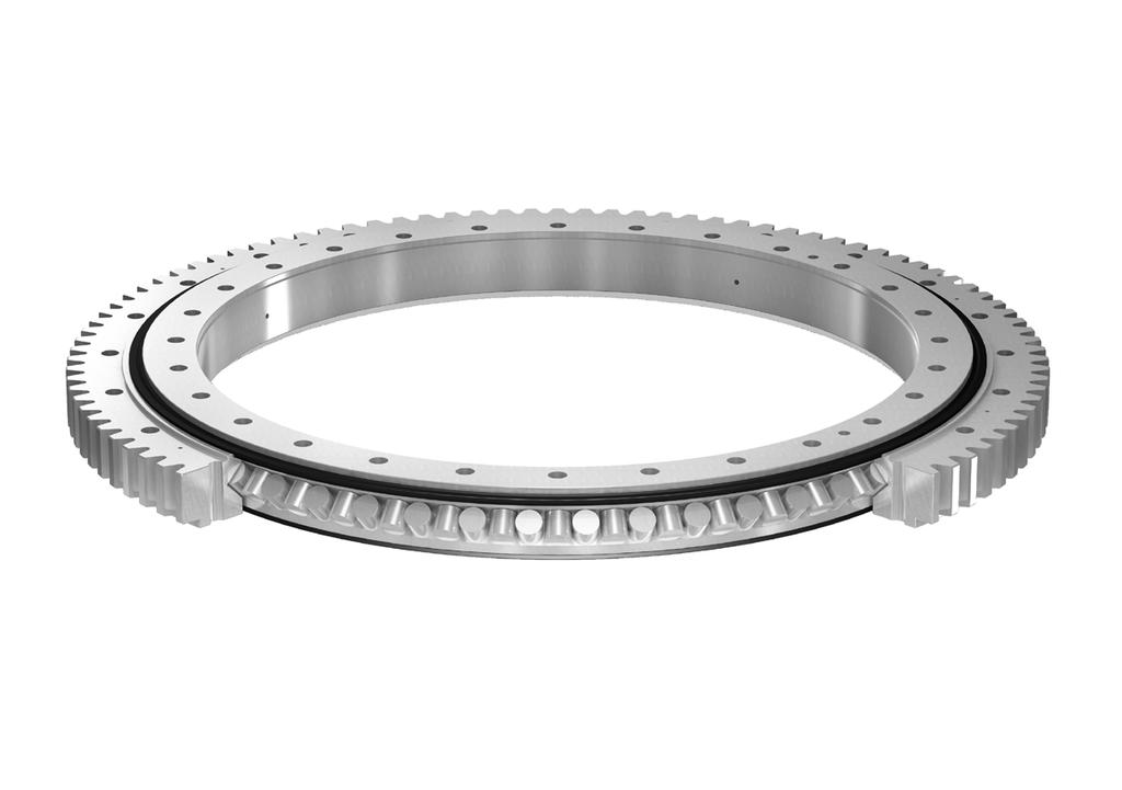

84
85 Single row crossed cylindrical roller slewing bearings General 86 Designs Product data general 87 Medium size single row crossed cylindrical roller slewing bearings 88 Customized single row crossed cylindrical roller slewing bearings 89 Bearing data general 89 Dimensions 89 Tolerances 89 Axial clearance, preload 89 Material 90 Corrosion protection 90 Gears 90 Seals 4 90 Lubrication 91 Designation system 92 Product tables Medium size crossed cylindrical roller slewing bearings 92 with an external gear 96 with an internal gear 100 without a gear Customized crossed cylindrical roller slewing bearings 104 with an external gear 110 with an internal gear 114 without a gear 85


86 Product data general General Single row crossed cylindrical roller slewing bearings are simple in design, consisting of a one-piece inner and outer ring and cylindrical rollers separated by polyamide spacers and generally protected by integral seals.they can accommodate heavy radial loads and medium axial loads as well as tilting moments. These SKF slewing bearings are intended for bearing arrangements where stiffness is important or zero operational clearance or preload as well as constant resistance to rotation are required. Single row crossed cylindrical roller slewing bearings require tighter specifications for the flatness and stiffness of the support surface than single row four-point contact ball slewing bearings. Due to the wide range of applications for single row crossed cylindrical roller slewing bearings, SKF manufactures them in many executions and sizes that are available from stock or within short lead times. The actual SKF manufacturing range of customized bearings is more extensive than what appears in the product tables. SKF manufactures a variety of customized single row crossed cylindrical roller slewing bearings to meet the demands of particular applications. Customized executions can include special ring materials and unique bolt patterns. Load carrying ability, speed capability, and/or running accuracy can also be customized. A customized slewing bearing that meets your specific requirements might already exist. Therefore, SKF recommends contacting the application engineering service very early in the design stage so that SKF engineers, with their in-depth product and application knowledge, can help you find the most suitable bearing arrangement for your application. Designs Single row crossed cylindrical roller slewing bearings consist of a one-piece inner and outer ring and a set of cylindrical rollers and spacers, protected by integral seals. The cylindrical rollers are inserted into the bearing via a hole in one of the two rings and are separated by poly amide spacers. The axis of rotation of adjacent rollers are at 90 to each other. After loading the roller set and spacers, the hole is closed with a plug that conforms to the raceway contour. The SKF range of single row crossed cylindrical roller slewing bearings is divided into: medium size single row crossed cylindrical roller slewing bearings customized single row crossed cylindrical roller slewing bearings 86
87 Medium size single row crossed cylindrical roller slewing bearings Fig. 1 SKF medium size single row crossed cylindrical roller slewing bearings are compact, with strong, full-size rings. Depending on the size, they are available with two different fixed cross-sections within each of the three series. To simplify installation, the inner and outer rings have a standardized number of equally spaced holes for attachment bolts. The standard SKF single row medium size crossed roller slewing bearings ( fig. 1) listed in the product tables include bearings with a mean raceway diameter ranging from 414 to mm and are available with any of the following gear configurations: a with an external gear (a), RKS. 161 series designation with an internal gear (b), RKS. 162 series designation without a gear (c), RKS. 160 series designation These slewing bearings are available from stock or within short lead times. For up-todate information about availability, contact the SKF application engineering service. SKF medium size crossed cylindrical roller slewing bearings feature a unique and costeffective combination of load carrying ability, stiffness, and speed capability. These features open a wide application field for medium size crossed cylindrical roller slewing bearings. Typical applications include, but are not limited to, earth moving, construction and material handling equipment as well as robotics. Medium size crossed cylindrical roller slewing bearings can be operated continuously at circumferential speeds of up to 1.5 m/s and up to 2 m/s for brief periods. b c 4 87
88 Fig. 2 Customized single row crossed cylindrical roller slewing bearings a SKF manufactures single row crossed cylindrical roller slewing bearings in a variety of executions and sizes to meet the needs of particular applications. The customized SKF single row crossed cylindrical roller slewing bearings ( fig. 2) listed in the product tables include bearings with a mean raceway diameter ranging from 310 to mm and are available with any of the following gear configurations or options: with an external gear (a) with an internal gear (b) without a gear (c) with (c) or without centring recesses b These customized bearings represent only a few designs and sizes, which are manufactured on a regular basis or within short lead times. Before incorporating a customized bearing in an application design, contact the SKF application engineering service for availability. Depending on design, size and accuracy, customized single row crossed cylindrical roller slewing bearings can be operated at circumferential speeds of up to 1,5 m/s and up to 2 m/s for brief periods. For applications that will operate at higher speeds than those listed in the tables, contact the SKF application engineering service. c 88
89 Bearing data general Table 1 Dimensions The boundary dimensions of single row crossed cylindrical roller slewing bearings are dictated by practical application requirements and do not comply with any international or national standard. Medium size bearings up to and including mm mean raceway diameter are dimensionally interchangeable with competitors products. Diameter tolerances Nominal diameter Diameter tolerances Ungeared Centring diameters 1) Bolt hole inner and/or Inside Outside pitch circle outer diameter diameters over incl. (d, D) (d 2c, D 2c ) (d 1c, D 1c ) (J i, J e ) mm mm ±1 0/+0,2 0/ 0,2 ±0, ±1 0/+0,3 0/ 0,3 ±0, ±1 0/+0,35 0/ 0,35 ±0,6 Tolerances The dimensional and running accuracy of SKF single row crossed cylindrical roller slewing bearings are listed in: ±1 0/+0,4 0/ 0,4 ±0, ±1 0/+0,4 0/ 0,4 ±1 table 1: Diameter tolerances ( fig. 3) table 2: Tolerances of tip circle and attachment bolt hole diameters ( fig. 3) table 3: Running accuracy 1) Applies only to customized bearings Tolerances of tip circle and attachment bolt hole diameters Table 2 The tolerance for the total height H is ±1 mm for all single row crossed cylindrical roller slewing bearings. Tip circle diameters D G and d G Bolt hole diameters K e and K i Module Tolerances Nominal Tolerance m External gear Internal gear diameter mm Axial clearance, preload Crossed cylindrical roller slewing bearings are manu factured with zero clearance or preload. Material The rings of medium size crossed cylindrical roller slewing bearings up to a mean raceway diameter of mm are made as standard of C 45 E tempered steel, in accordance with EN :2006. Crossed cylindrical roller slewing bearings with a mean raceway dia meter larger than mm are made of 42CrMo4 bearing steel for induction hardening, in accordance with EN :2006. The rings of customized crossed cylindrical roller slewing bearings listed in the product tables starting on page 102 are produced either from 5 0/ 0,25 0/+0,25 11 ±0,3 6 0/ 0,3 0/+0,3 14 ±0,3 8 0/ 0,4 0/+0,4 16 ±0,4 10 0/ 0,5 0/+0,5 18 ±0,4 14 0/ 0,7 0/+0,7 22 ±0,4 16 0/ 0,8 0/+0,8 N e d 1 J i d 1c J i d 2c d 2 d d G Fig. 3 4 a modified heat-treatable 42 C 2 steel, in accordance with NFA :1983, or 46Cr2 steel, in accordance to EN a 42CrMo4 bearing steel for induction hardening, in accordance with EN :2006 H N i D 2c D 2 J e J e Inner and outer ring raceways are surface induction-hardened while leaving the remainder of the rings, including the gears, unaffected by the hardening process. D 1 D G D 1c D 89
90 The cylindrical rollers are made of 100Cr6 bearing steel for through-hardening, in accordance with EN ISO :2000. Corrosion protection Single row crossed cylindrical roller slewing bearings are protected, as standard, by a solvent free rust inhibitor. Gears The gear teeth are manufactured to an SKF specification that closely follows accuracy grade 12 in accordance with ISO :1997 and are not hardened. Guideline values for the permissible tooth forces can be obtained from the product tables. The gear of a new bearing is coated with a preservative. After mounting has been completed, lubricant needs to be applied to the gear. This lubricant should have good adhesive properties and high resistance to water washout. Additionally, the lubricant has to withstand at least temperatures of +100 C and has to have a base oil viscosity of 500 mm 2 /s at +40 C or higher. Running accuracy Nominal mean Running accuracy raceway diameter Medium size bearings Customized bearings d m Radial Axial Radial Axial runout 1) runout 2) runout 1) runout 2) over incl. max max max max mm mm ,2 0,3 0,2 0, ,3 0,4 0,3 0, ,35 0,5 0,35 0, ,45 0,6 0,4 0, ,5 0,7 0,45 0,25 1) Radial runout of the centring of inner or outer ring of assembled bearing 2) Axial runout of the mating surface of inner or outer ring of assembled bearing Table 3 Fig. 4 Seals a b The integral seals are made of profiled strips of non-reinforced acrylonitrile-butadiene rubber (NBR). They seal axially against the side face of the inner or outer ring ( fig. 4a) or radially against the cylindrical surface of the inner or outer ring ( fig. 4b). This material has very good engineering properties and shows good resistance to most mineral oils and greases. The permissible operating temperatures of the seal material range from 40 to C. a Fig. 5 Lubrication Standard SKF single row crossed cylindrical roller slewing bearings are filled with a mineral oil based grease with a consistency of 2 on the NLGI scale using a lithium soap thickener and containing extreme pressure additives. The base oil viscosity is 200 mm 2 /s at 40 C and 16 mm 2 /s at 100 C. This grease has good rust inhibiting properties and a temperature range of 20 up to +110 C. Reliable lubrication according to the SKF traffic light concept occurs when operating temperatures range from +30 to +110 C. b c 90
91 Medium size single row crossed cylindrical roller slewing bearings can be relubricated through four equally spaced grease fittings A M 10 1 to DIN 71412:1987: in the inner ring of bearings with an external gear ( fig. 5a) in the outer ring of bearings with an internal gear ( fig. 5b) in the outer ring of bearings without a gear Relubrication features of customized slewing bearings ( fig. 5c) depend on the needs of the application. For additional information, contact the SKF application engineering service. Guidelines to determine relubrication intervals for slewing bearings in vertical arrangements under normal and clean conditions are provided in the chapter Lubrication, starting on page 26. Designation system The designation system for SKF medium size crossed roller slewing bearings consists only of a few figures, the significance of which is described in table 5. The designation system for SKF customized slewing bearings consists of several figures and is described briefly in table 6 "Designation system of customized slewing bearings" on page 59. Designation system of medium size crossed cylindrical roller slewing bearings Examples: RKS RKS Bearing identification RKS Series identification SKF slewing bearing 16 Medium size crossed cylindrical roller slewing bearing Identification of gear position 0 Without a gear 1 With an external gear 2 With an internal gear Roller size identification mm roller diameter mm roller diameter mm roller diameter Identification of bearing size mm mean raceway diameter to mm mean raceway diameter RKS RKS Table series 161 series 162 series without a gear with an external gear with an internal gear 91
92 Medium size crossed cylindrical roller slewing bearings with an external gear d m mm d m d 1 K i N i j 1 d 56 44, ,5 K e N e D 1 J e d 0 D Dimensions Attachment bolt holes Mass Designation Outer ring Inner ring d m D D 1 d d 1 J e K e N e J i K i N i mm mm mm kg M ,0 RKS , M ,0 RKS , M ,0 RKS , M ,0 RKS , M ,0 RKS , M ,0 RKS , M ,0 RKS Relubrication can be done through 4 equally spaced grease fittings A M10 1 to DIN in the inner ring. 92
93 Tilting moment, knm b7 b6 200 b5 b4 100 b2 b3 b1 r5 r1 r2 r3 r4 r6 r Axial load, kn Designation Gear Basic load ratings Static limiting Dimensions Permissible axial load diagram tooth forces dynamic static Raceway Bolt d 0 1) m z k m T fnormal 2) T fmax C C 0 curves curves mm mm kn kn RKS , r1 b1 4 RKS , r2 b2 RKS , r3 b3 RKS , r4 b4 RKS , r5 b5 RKS , r6 b6 RKS , r7 b7 1) Gear pitch circle diameter 2) Normalized gear teeth; calculated for operating cycles 93
94 Medium size crossed cylindrical roller slewing bearings with an external gear d m mm d m d 1 K i N i J i d K e N e D 1 J e D Dimensions Attachment bolt holes Mass Designation Outer ring Inner ring d m D D 1 d d 1 J e K e N e J i K i N i mm mm mm kg RKS RKS RKS RKS RKS RKS , RKS Relubrication can be done through 4 equally spaced grease fittings A M10 1 to DIN in the inner ring. 94
95 Tilting moment, knm b b6 b b3 b b2 b1 r4 r6 200 r1 r2 r3 r5 r Axial load, kn Designation Gear Basic load ratings Static limiting Dimensions Permissible axial load diagram tooth forces dynamic static Raceway Bolt d 0 1) m z x m k m T fnormal 2) T fmax C C 0 curves curves mm mm kn kn RKS r1 b1 4 RKS r2 b2 RKS r3 b3 RKS r4 b4 RKS , r5 b5 RKS , r6 b6 RKS ,1 1, r7 b7 1) Gear pitch circle diameter 2) Normalized gear teeth; calculated for operating cycles 95
96 Medium size crossed cylindrical roller slewing bearings with an internal gear d m mm D J e N e K e D 1 d m 28 44, ,5 K i N i d d 0 J i d 1 Dimensions Attachment bolt holes Mass Designation Outer ring Inner ring d m D D 1 d d 1 J e K e N e J i K i N i mm mm mm kg M ,0 RKS M ,0 RKS M ,0 RKS M ,0 RKS M ,0 RKS M ,0 RKS M ,0 RKS Relubrication can be done through 4 equally spaced grease fittings A M10 1 to DIN in the outer ring. 96
97 Tilting moment, knm b7 b6 200 b5 b4 100 b2 b3 b1 r5 r1 r2 r3 r4 r6 r Axial load, kn Designation Gear Basic load ratings Static limiting Dimensions Permissible axial load diagram tooth forces dynamic static Raceway Bolt d 0 1) m z k m T fnormal 2) T fmax C C 0 curves curves mm mm kn kn RKS , r1 b1 4 RKS , r2 b2 RKS , r3 b3 RKS , r4 b4 RKS , r5 b5 RKS , r6 b6 RKS , r7 b7 1) Gear pitch circle diameter 2) Normalized gear teeth; calculated for operating cycles 97
98 Medium size crossed cylindrical roller slewing bearings with an internal gear d m mm D N e K e J e D 1 d m K i N i d d 0 J i d 1 Dimensions Attachment bolt holes Mass Designation Outer ring Inner ring d m D D 1 d d 1 J e K e N e J i K i N i mm mm mm kg RKS , RKS , RKS , RKS , RKS , RKS , RKS Relubrication can be done through 4 equally spaced grease fittings A M10 1 to DIN in the outer ring. 98
99 Tilting moment, knm b b6 b b3 b b2 b1 r4 r6 200 r1 r2 r3 r5 r Axial load, kn Designation Gear Basic load ratings Static limiting Dimensions Permissible axial load diagram tooth forces dynamic static Raceway Bolt 1) d 0 m z x m k m 2) T fnormal T fmax C C 0 curves curves mm mm kn kn RKS , r1 b1 4 RKS , r2 b2 RKS , r3 b3 RKS , r4 b4 RKS , r5 b5 RKS , r6 b6 RKS ,65 1, r7 b7 1) Gear pitch circle diameter 2) Normalized gear teeth; calculated for operating cycles 99
100 Medium size crossed cylindrical roller slewing bearings without a gear d m mm d m K i N i d 1 J i d 56 44, ,5 N e K e D 1 J e D Dimensions Attachment bolt holes Mass Designation Outer ring Inner ring d m D D 1 d d 1 J e K e N e J i K i N i mm mm mm kg ,0 RKS ,0 RKS ,0 RKS ,0 RKS ,0 RKS ,0 RKS ,0 RKS Relubrication can be done through 4 equally spaced grease fittings A M10 1 to DIN in the outer ring. 100
101 Tilting moment, knm b7 b6 200 b5 b4 100 b2 b3 b1 r5 r1 r2 r3 r4 r6 r Axial load, kn Designation Basic load ratings Static limiting axial load diagram dynamic static Raceway Bolt C C 0 curves curves kn RKS r1 b1 4 RKS r2 b2 RKS r3 b3 RKS r4 b4 RKS r5 b5 RKS r6 b6 RKS r7 b7 101
102 Medium size crossed cylindrical roller slewing bearings without a gear d m mm d m d 1 K i N i J i d N e K e D 1 J e D Dimensions Attachment bolt holes Mass Designation Outer ring Inner ring d m D D 1 d d 1 J e K e N e J i K i N i mm mm mm kg RKS , RKS , RKS , RKS , RKS , RKS , RKS Relubrication can be done through 4 equally spaced grease fittings A M10 1 to DIN in the outer ring. 102
103 Tilting moment, knm b b6 b b2 b1 b3 b4 r4 r6 200 r1 r2 r3 r5 r Axial load, kn Designation Basic load ratings Static limiting axial load diagrams dynamic static Raceway Bolt C C 0 curves curves kn RKS r1 b1 4 RKS r2 b2 RKS r3 b3 RKS r4 b4 RKS r5 b5 RKS r6 b6 RKS r7 b7 103
104 Customized crossed cylindrical roller slewing bearings with an external gear d m mm d m d 1 H C C 1 K i N i J i d 2 B 1 H 1 B 10 Design N K e e d D 2 J e D 1 d 0 D Design 1 Design 3 Dimensions Mass Designation Slewing bearing Outer ring Inner ring d m D d H H 1 D 1 D 2 C C 1 d 1 d 2 B B 1 mm mm mm kg , ,0 RKS , ,0 RKS ,0 RKS RKS
105 Tilting moment, knm b b2 b3 50 b1 r1 r2 r3 r Axial load, kn Designation De- Attachment bolt holes Gear Basic load ratings Static limiting sign Outer ring Inner ring Dimensions Permissible axial load diagram tooth forces dynamic static Raceway Bolt J e K e N e J i K i N i 1) d 0 m z x m k m 2) T fnormal T fmax C C 0 curves curves mm mm mm mm kn kn RKS ) 396 4, , r1 b1 4 RKS ,5 4, r2 b2 RKS r3 b3 RKS ,552 0, r4 b4 1) Gear pitch circle diameter 2) Normalized gear teeth; calculated for operating cycles 3) Attachment bolt holes not equally spaced 105
106 Customized crossed cylindrical roller slewing bearings with an external gear d m mm D 3 N i K i d m d 1 J i d 2 4 B 1 H C C 1 H 1 B Design 4 D 2 N K e e d D 2 J e D 1 d 0 D 25 Design 1 Design 5 Dimensions Mass Designation Slewing bearing Outer ring Inner ring d m D d H H 1 D 1 D 2 D 3 C C 1 d 1 d 2 B B 1 mm mm mm kg ,0 RKS RKS RKS RKS , RKS RKS
107 Tilting moment, knm b9 800 b b8 400 b6 200 b7 b5 r5 r7 r6 r8 r10 r Axial load, kn Designation De- Attachment bolt holes Gear Basic load ratings Static limiting sign Outer ring Inner ring Dimensions Permissible axial load diagram tooth forces dynamic static Raceway Bolt J e K e N e J i K i N i d 0 1) m z x m k m T fnormal 2) T fmax C C 0 curves curves mm mm mm mm kn kn RKS M M r5 b5 4 RKS ) ) , r6 b6 RKS M M r7 b7 RKS ) ) r8 b8 RKS ,5 0, r9 b9 RKS ,08 1, r10 b10 1) Gear pitch circle diameter 2) Normalized gear teeth; calculated for operating cycles 3) Attachment bolt holes not equally spaced 107
108 Customized crossed cylindrical roller slewing bearings with an external gear d m mm N i K i d m d 1 J i d 2 H C C 1 B 1 H 1 B Design 6 D 2 6 N K e e d D 2 J e D 1 d 0 D Design 1 Design 7 D 2 Dimensions Mass Designation Slewing bearing Outer ring Inner ring d m D d H H 1 D 1 D 2 C C 1 d 1 d 2 B B 1 mm mm mm kg , , , RKS , , , RKS , , , RKS , , RKS , , RKS
109 Tilting moment, knm b b11 b r11 r12 r Axial load, kn Designation De- Attachment bolt holes Gear Basic load ratings Static limiting sign Outer ring Inner ring Dimensions Permissible axial load diagram tooth forces dynamic static Raceway Bolt J e K e N e J i K i N i d 0 1) m z x m k m T fnormal 2) T fmax C C 0 curves curves mm mm mm mm kn kn RKS ,6 0, r11 b11 4 RKS ,3 3, r11 b11 RKS ,3 3, r11 b11 RKS ) ,5 0, r12 b12 RKS M ) ) ,912 2, r13 b13 1) Gear pitch circle diameter 2) Normalized gear teeth; calculated for operating cycles 3) Attachment bolt holes not equally spaced 109
110 Customized crossed cylindrical roller slewing bearings with an internal gear d m mm C 1 K e N e D D 1 J e D 2 d m 30 C Design 2 H H 1 B 1 B N i K i d d 0 d 2 J i d /8-11 UNC Design 1 Design 3 Dimensions Mass Designation Slewing bearing Outer ring Inner ring d m D d H H 1 D 1 D 2 C C 1 d 1 d 2 B B 1 mm mm mm kg , ,0 RKS , RKS , RKS , RKS RKS
111 Tilting moment, knm b5 b4 400 b b b1 r1 r2 r3 r4 r Axial load, kn Designation De- Attachment bolt holes Gear Basic load ratings Static limiting sign Outer ring Inner ring Dimensions Permissible axial load diagram tooth forces dynamic static Raceway Bolt J e K e N e J i K i N i 1) d 0 m z x m k m 2) T fnormal T fmax C C 0 curves curves mm mm mm mm kn kn RKS , r1 b1 4 RKS ) ) ,5 0, r2 b2 RKS M M , r3 b3 RKS M / ,04 10, ,7 2, r4 b4 RKS M M , r5 b5 1) Gear pitch circle diameter 2) Normalized gear teeth; calculated for operating cycles 3) Attachment bolt holes not equally spaced 111
112 Customized crossed cylindrical roller slewing bearings with an internal gear d m mm K e N e D J e D 2 d m Design 4 H 1 35 H C B 1 B N i K i 30 d Design d 0 d 2 J i d 1 16 M Design 3 32 Design 6 M Dimensions Slewing bearing Outer ring Inner ring Mass Designation d m D d H H 1 D 2 C d 1 d 2 B B 1 mm mm mm kg ,1 105,5 49, ,5 91,5 260 RKS ,1 105,5 49, ,5 91,5 260 RKS ,5 49, ,5 260 RKS , , , RKS , ,8 104,65 52, ,25 92, , ,9 87,9 425 RKS , , , RKS RKS
113 Tilting moment, knm b b8 b b7 b6 b r6 r r8 r r r Axial load, kn 4 Designation De- Attachment bolt holes Gear Basic load ratings Static limiting sign Outer ring Inner ring Dimensions Permissible axial load diagram tooth forces dynamic static Raceway Bolt J e K e N e J i K i N i d 0 1) m z x m k m T fnormal 2) T fmax C C 0 curves curves mm mm mm mm kn kn RKS ) M ,666 0, r6 b6 RKS ) M ,666 0, r6 b6 RKS M r7 b7 RKS ) , r8 b8 RKS , ) 1 149, ,61 10, ,016 2, r9 b9 RKS M , r10 b10 RKS M M , r11 b11 1) Gear pitch circle diameter 2) Normalized gear teeth; calculated for operating cycles 3) Attachment bolt holes not equally spaced 113
114 Customized crossed cylindrical roller slewing bearings without a gear d m mm d m d 1 C C 1 K i N i B 1 H 1 B J i d 2 H Design N i K e d D 2 J e D 1 D C 4 C 1 Design 1 Design Dimensions Mass Designation Slewing bearing Outer ring Inner ring d m D d H H 1 D 1 D 2 C C 1 d 1 d 2 B B 1 mm mm mm kg , ,0 RKS , ,0 RKS ,0 RKS RKS RKS RKS
115 Tilting moment, knm b6 500 b b4 r b2 b3 r5 b1 r1 r2 r3 r Axial load, kn Designation De- Attachment bolt holes Basic load ratings Static limiting sign Outer ring Inner ring axial load diagram dynamic static Raceway Bolt J e K e N e J i K i N i C C 0 curves curves mm mm kn RKS r1 b1 4 RKS r2 b2 RKS r3 b3 RKS r4 b4 RKS r5 b5 RKS ) ) r6 b6 1) Attachment bolt holes not equally spaced 115
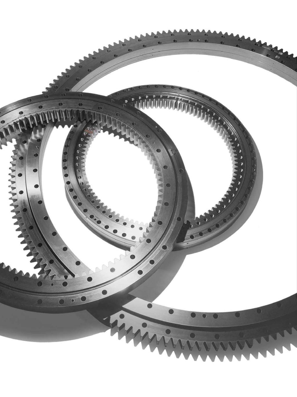
116
The SKF brand now stands for more than ever before, and means more to you as a valued customer.
 Slewing bearings The SKF brand now stands for more than ever before, and means more to you as a valued customer. While SKF maintains its leadership as the hallmark of quality bearings throughout the world,
SKF Xtra Power Belts. V-belts designed for maximum performance
 SKF Xtra Power Belts V-belts designed for maximum performance 1 SKF Xtra Power Belts SKF Xtra Power Belts have been designed to deliver up to 40% more power than standard wrapped belts. In addition, these
SKF stainless steel deep groove ball bearings. Reliable bearing solutions for corrosive environments
 SKF stainless steel deep groove ball bearings Reliable bearing solutions for corrosive environments 2 Contents A A Product information SKF the knowledge engineering company... 4 B Recommendations Demanding
SKF Energy Efficient Y-bearings. Reduced friction for reduced energy use
 SKF Energy Efficient Y-bearings Reduced friction for reduced energy use 2 Contents SKF the knowledge engineering company.... 4 SKF Energy Efficient bearings.... 6 Engineered to promote sustainability....
Axial-radial cylindrical roller bearings
 Axial-radial cylindrical roller bearings Designs and variants.............. 320 Bearing data..................... 321 (Boundary dimensions, tolerances) Product table 5.1 Axial-radial cylindrical roller
SKF Energy Efficient deep groove ball bearings. Reduced friction for reduced energy use
 SKF Energy Efficient deep groove ball bearings Reduced friction for reduced energy use SKF Energy Efficient bearings Engineered to promote sustainability As the need to conserve energy grows more apparent
Drawn cup needle roller bearings
 Drawn cup needle roller bearings Sealed drawn cup needle roller bearings... 78 Full complement drawn cup needle roller bearings... 79 3 Dimensions... 79 Tolerances... 79 Misalignment... 80 Cages... 80
4 Self aligning ball bearings
 Rolling bearings 4 Self aligning ball bearings Designs and variants... 538 Basic design bearings... 539 Bearings with an extended inner ring.. 540 Cages... 540 Sealing solutions... 540 Greases for sealed
15E INSOCOAT bearings
 15E INSOCOAT bearings Designs and variants............... 1206 INSOCOAT bearings with a coated outer ring......................... 1207 INSOCOAT bearings with a coated inner ring.........................
10 Thrust ball bearings
 10 Thrust ball bearings Designs and variants.............. 1010 Single direction thrust ball bearings... 1010 Double direction thrust ball bearings.. 1010 Cages............................ 1010 Bearings
SKF Power transmission belts
 SKF Power transmission belts Contents Foreword.... 3 SKF the knowledge engineering company.... 4 1 V-belts Product features SKF Wrapped Wedge and SKF Wrapped Narrow Wedge Belts............... 8 SKF Xtra
14 Track runner bearings
 14 Track runner bearings Designs and variants............... 1100 Cam rollers... 1100 Single row cam rollers............. 1100 Double row cam rollers............ 1100 Support rollers... 1101 Support rollers
Super-precision cylindrical roller bearings: High-speed. N 10 series
 Super-precision cylindrical roller bearings: High-speed N 10 series Contents A Product information High-speed super-precision single row cylindrical roller bearings... 3 The assortment... 4 High-speed
SLEWING RING CHARACTERISTICS, APPLICATIONS
 SLEWING RING CHARACTERISTICS, APPLICATIONS Slewing rings are large-sized bearings which are able to accommodate combined load, i.e. axial, radial loads and tilting moment. They are usually provided with
SKF high temperature bearings
 SKF high temperature bearings For operating temperatures up to 350 C (660 F) The Power of Knowledge Engineering Contents SKF the knowledge engineering company.... 4 Reduce maintenance. Run Longer. Run
bearings (metric series)
") Taper roller bearings (metric series) 32302 B J2 / Q CL7C Nomenclature 1 2 3 4 1. Contact angle: 3. Features: B Larger contact angle than standard Q Improved friction torque characteristics and raceway
Taper roller bearings (metric series) 32302 B J2 / Q CL7C Nomenclature 1 2 3 4 1. Contact angle: 3. Features: B Larger contact angle than standard Q Improved friction torque characteristics and raceway
Angular contact ball bearings
 Angular contact ball bearings Single row angular contact ball bearings... 409 Double row angular contact ball bearings... 433 Four-point contact ball bearings... 451 Double row cam rollers... 463 405 Angular
Sealed SKF single row angular contact ball bearings. Robust, cost-effective and interchangeable
 Sealed SKF single row angular contact ball bearings Robust, cost-effective and interchangeable Sealed SKF single row angular contact bearings have an attractive combination of design features such as low
INSOCOAT bearing designs INSOCOAT bearings with coated outer ring INSOCOAT bearings with coated inner ring
 INSOCOAT bearings INSOCOAT bearing designs... 913 INSOCOAT bearings with coated outer ring... 913 INSOCOAT bearings with coated inner ring... 913 Other INSOCOAT bearings... 913 Bearing data general...
Flanged housings FNL series
 Flanged housings FNL series Bearing types Self-aligning ball bearings Spherical roller bearings CARB toroidal roller bearings Bearing dimension series 02, 22 FNL flanged housings are well-proven machine
SKF Power Transmission products
 SK Power Transmission products SK is a registered trademark of the SK Group. ytrel is a registered trademark of DuPont. Dacromet and Dacrotized are registered trademarks of Metal Coatings International
Super-precision axial-radial cylindrical roller bearings. For applications requiring a higher degree of accuracy and rigidity
 Super-precision axial-radial cylindrical roller bearings For applications requiring a higher degree of accuracy and rigidity Condition monitoring Precision lock nuts Precision lock nuts Seals Gear pump
Profile rail guides LLT
 Profile rail guides LLT Contents The SKF brand now stands for more than ever before, and means more to you as a valued customer. While SKF maintains its leadership as the hallmark of quality bearings throughout
SKF Power Transmission products
 SK Power Transmission products SK is a registered trademark of the SK Group. ytrel is a registered trademark of DuPont. Dacromet and Dacrotized are registered trademarks of Metal Coatings International
CLASSIFICATION OF ROLLING-ELEMENT BEARINGS
 CLASSIFICATION OF ROLLING-ELEMENT BEARINGS Ball bearings can operate at higher speed in comparison to roller bearings because they have lower friction. In particular, the balls have less viscous resistance
Split pillow blocks SDAF series including the extended range (inch dimensions)
") Split pillow blocks SDAF series including the extended range (inch dimensions) Bearing types Spherical roller bearings CARB toroidal roller bearings Bearing dimension series 22, 23 (SDAF) 30, 31, 32 (SDAF
Split pillow blocks SDAF series including the extended range (inch dimensions) Bearing types Spherical roller bearings CARB toroidal roller bearings Bearing dimension series 22, 23 (SDAF) 30, 31, 32 (SDAF
Cylindrical roller bearings for large electric motors
 Cylindrical roller bearings for large electric motors Cylindrical roller bearings are typically used in belt or gear driven medium- to largesized electric motors, where heavy radial loads prevail. These
Sealed SKF spherical roller bearings for demanding environments
 Sealed bearings Page... 18 Page... 32 Sealed SKF spherical roller bearings for demanding environments Sealed SKF spherical roller bearings are designed to fulfil high demands on sealing efficiency and
Single direction thrust ball bearings Double direction thrust ball bearings
 Thrust ball bearings Single direction thrust ball bearings... 838 Double direction thrust ball bearings... 839 Bearing data general... 840 Dimensions... 840 Tolerances... 840 Misalignment... 840 Cages...
Product Line Overview/Comparison
 Product Line Overview/Comparison Design types Series Sizes Raceway diameters Maximum torque 1) Maximum tilting moment 1) 2) Static axial load rating Load carrying capacity 1) Static radial load rating
Track Rollers/ Cam Followers
 Track Rollers/ Cam Followers Page Nomenclature...................................... 460 Introduction....................................... 462 Identification....................................... 462
TRANSLATION (OR LINEAR)
") 5) Load Bearing Mechanisms Load bearing mechanisms are the structural backbone of any linear / rotary motion system, and are a critical consideration. This section will introduce most of the more common
5) Load Bearing Mechanisms Load bearing mechanisms are the structural backbone of any linear / rotary motion system, and are a critical consideration. This section will introduce most of the more common
SKF Explorer angular contact ball bearings. Designed to run faster, cooler, smoother, longer
 SKF Explorer angular contact ball bearings Designed to run faster, cooler, smoother, longer Improve performance and increase service life Screw compressors, pumps and gearboxes require bearing arrangements
Miniature Ball Rail Systems
 R310EN 2210 (2004.06) The Drive & Control Company 2 Bosch Rexroth AG Linear Motion and Assembly Technologies Miniature-BRS R310EN 2210 (2004.06) Linear Motion Systems Ball Rail System Standard Ball Rail
Super-precision double direction angular contact thrust ball bearings. BTW series
 Super-precision double direction angular contact thrust ball bearings BTW series SKF the knowledge engineering company From one simple but inspired solution to a misalignment problem in a textile mill
Kaydon white paper. Slewing bearing selection, simplified. an SKF Group brand. by Jeff Lauber, engineering specialist
 Slewing bearing selection, simplified by Jeff Lauber, engineering specialist an SKF Group brand Selecting the right slewing bearing Slewing bearings are typically used in applications where their ability
Y-bearings and Y-bearing units
 Y-bearings and Y-bearing units SKF is a registered trademark of the SKF Group. SKF Group 2013 The contents of this publication are the copyright of the publisher and may not be reproduced (even extracts)
High Precision Bearings for Combined Loads
 High Precision Bearings for Combined Loads Axial/radial bearings Axial angular contact ball bearings Axial/radial bearings with angular measuring system added competence for your success With their forward-looking
Courtesy of CMA/Flodyne/Hydradyne Motion Control Hydraulic Pneumatic Electrical Mechanical (800)
") 01_1 Miniature st Headline_36 Ball Rail pt/14.4 Systems mm second line 2 Linear Motion and Assembly Technologies Miniature Ball Rail Systems Ball Rail Systems Roller Rail Systems Linear Bushings and Shafts
01_1 Miniature st Headline_36 Ball Rail pt/14.4 Systems mm second line 2 Linear Motion and Assembly Technologies Miniature Ball Rail Systems Ball Rail Systems Roller Rail Systems Linear Bushings and Shafts
Shifting gears: simplify your design with slewing ring bearings
 White Paper Shifting gears: simplify your design with slewing ring bearings Scott Hansen, VP, Manufacturing Planning, Kaydon Bearings, an SKF Group company A slewing ring bearing has rolling elements designed
Labyrinth seals for INA ball bearings
 Labyrinth seals for INA ball bearings Dipl.-Ing. Günter Gerhart and Dipl.-Ing. Michael Kurz INA reprint October 1995 Labyrinth seals for INA ball bearings Dipl.-Ing. Günter Gerhart and Dipl.-Ing. Michael
Heavy-Duty Rod Ends - Male with integral spherical plain bearing
 Heavy-Duty Rod Ends - Male with integral spherical plain bearing 65700 Order No. Thread (hand) d 1 l 1 d 2 d 3 d 4 l 2 l 3 X g H7 65700.W0005 Right 5 33 M 5 11,11 18 20 9 14 65700.W0006 Right 6 36 M 6
SKF high temperature bearings. For operating temperatures up to 350 C (660 F)
") SKF high temperature bearings For operating temperatures up to 350 C (660 F) Contents SKF the knowledge engineering company... 4 Reduce maintenance. Run Longer. Run Cleaner.... 7 SKF high temperature
SKF high temperature bearings For operating temperatures up to 350 C (660 F) Contents SKF the knowledge engineering company... 4 Reduce maintenance. Run Longer. Run Cleaner.... 7 SKF high temperature
SKF Xtra Power Lawn and Garden belts
 SKF Xtra Power Lawn and Garden belts SKF is a registered trademark of the SKF Group. Dacromet and Dacrotized are registered trademarks of Metal Coatings International Inc. Corporation. SKF Group 2015 The
SKF high-capacity cylindrical roller bearings. Full complement bearings with a cage
 SKF high-capacity cylindrical roller bearings Full complement bearings with a cage Higher load ratings and longer service life Applications like industrial gearboxes, gearboxes in wind turbines or machines
R310EN 2211 ( ) The Drive & Control Company
 The Drive & Control Company") eline Ball Rail Systems R310EN 2211 (2006.04) The Drive & Control Company Bosch Rexroth AG Linear Motion and Assembly Technologies Ball Rail Systems Roller Rail Systems Linear Bushings and Shafts Ball
eline Ball Rail Systems R310EN 2211 (2006.04) The Drive & Control Company Bosch Rexroth AG Linear Motion and Assembly Technologies Ball Rail Systems Roller Rail Systems Linear Bushings and Shafts Ball
Rolling bearings and seals in electric motors and generators
 Rolling bearings and seals in electric motors and generators SKF, @PTITUDE, BAKER, CARB, DUOFLEX, DURATEMP, ICOS, INSOCOAT, MARLIN, MICROLOG, MONOFLEX, MULTILOG, SEAL JET, SKF EXPLORER, SYSTEM 24 and WAVE
Linear Motion Technology Handbook. The Drive & Control Company
 Linear Motion Technology Handbook The Drive & Control Company 1-2 Bosch Rexroth AG Linear Motion Technology Handbook R310EN 2017 (2006.07) Linear Motion and Assembly Technologies www.boschrexroth.com/brl
Wind Energy Solutions
 Wind Energy Solutions Around the world, wind turbine designers and operators are turning to Timken for power transmission and friction management solutions that increase uptime and improve total system
Profi le rail guides LLR
 Profi le rail guides LLR Content The SKF brand now stands for more than ever before, and means more to you as a valued customer. While SKF maintains its leadership as the hallmark of quality bearings throughout
SKF Explorer cylindrical roller bearings. Extended range for large, heavy industrial applications
 SKF Explorer cylindrical roller bearings Extended range for large, heavy industrial applications 2 A higher level of performance for large, heavy-duty applications The SKF Explorer performance class now
Bogie subsystems. Articulation joints. Extract from the Railway technical handbook, volume 1, chapter 9, page 172 to 175
 Bogie subsystems Articulation joints Extract from the Railway technical handbook, volume 1, chapter 9, page 172 to 175 Railway technical handbook Volume 1 Axleboxes, wheelset bearings, sensors, condition
Plain Bearings. For Everything That Moves
 Plain Bearings For Everything That Moves INA metal-polymer composite (MPC) plain bearings, maintenance free or low maintenance INA plain bearings with Elgotex, also available as segmented bearings INA
Chapter 11 Rolling Contact Bearings
 Chapter 11 Rolling Contact Bearings 1 2 Chapter Outline Bearing Types Bearing Life Bearing Load Life at Rated Reliability Bearing Survival: Reliability versus Life Relating Load, Life, and Reliability
High precision bearings for combined loads
 High precision bearings for combined loads Axial/radial bearings Axial angular contact ball bearings Axial/radial bearings with integral angular measuring system The right product for every application
Linear bearings and units. with SKF factory pre-lubrication
 Linear bearings and units with SKF factory pre-lubrication 2 Contents SKF - the knowledge engineering company... 4 The SKF factory pre-lubrication standard.... 7 Product overview... 8 Quadro linear tables,
Ball Rail Systems RE / The Drive & Control Company
 Ball Rail Systems RE 82 202/2002-12 The Drive & Control Company Rexroth Linear Motion Technology Ball Rail Systems Roller Rail Systems Standard Ball Rail Systems Super Ball Rail Systems Ball Rail Systems
SKF Energy Efficient double row angular contact ball bearings. Reduced friction for reduced energy use
 SKF Energy Efficient double row angular contact ball bearings Reduced friction for reduced energy use SKF Energy Efficient bearings Engineered to promote sustainability As the need to conserve energy grows
SKF Explorer spherical roller bearings Optimized for superior field performance
 SKF Explorer spherical roller bearings Optimized for superior field performance Continuous improvement to optimize The timeline below illustrates SKF milestones in the development of self-aligning bearings.
10 Thrust ball bearings
 Rolling bearings 10 Thrust ball bearings Designs and variants... 1010 Single direction thrust ball bearings... 1010 Double direction thrust ball bearings.. 1010 Cages... 1010 Bearings with sphered housing
Friction Management Solutions for Industrial Gear Drives
 Friction Management Solutions for Industrial Gear Drives A complete range of bearings and complementary services help the gear drive industry to meet ever-increasing requirements in product reliability
INDEX EASY RAIL: THE SOLUTION IS EASY...D4 EXAMPLES OF LOAD CAPACITIES...D5 ORDER CODES...D6 MOUNTING EXAMPLES...D7 TECHNICAL DATA...
 INDEX EASY RAIL: THE SOLUTION IS EASY...D4 EXAMPLES OF LOAD CAPACITIES...D5 ORDER CODES...D6 MOUNTING EXAMPLES...D7 TECHNICAL DATA...D8 STANDARD CONFIGURATIONS...D10 VERIFICATION UNDER STATIC LOAD...D12
SKF hub units. Equipped with tapered roller bearings
 SKF hub units Equipped with tapered roller bearings A passion for innovation Solutions for the demands of today and tomorrow SKF has always been known as a leader in the development of innovative bearing
Contents. Page. 1. Product description. 2. The AXC line of linear axes. 3. AXLT line of linear tables. AXC and AXS product overview...
 SNR Industry Contents Page 3 1. Product description AXC and AXS product overview... 6-8 Dynamic load ratings of the linear motion systems... 9 Compact modules... 10-11 Linear tables... 12 Telescopic axes...
SKF Energy Efficient Y-bearings. Reduced friction for reduced energy use
 SKF Energy Efficient Y-bearings Reduced friction for reduced energy use Contents The SKF brand now stands for more than ever before, and means more to you as a valued customer. While SKF maintains its
...our linkages, your solution. Rod Ends
 ...our linkages, your solution Technical Information Introduction All of our rod ends incorporate either a plain spherical bearing, ball bearing, or roller bearing. Below is an overview of each type. Plain
Cylindrical roller bearings
 Cylindrical roller bearings Cylindrical roller bearings are manufactured in a various range of constructive types and sizes, particularly single row cylindrical roller bearings but also two or more row
White Paper Bearing Lubrication
 White Paper Bearing Lubrication Lubrication of Rolling Bearings One of the most important requirements for effective function of bearing arrangements is proper lubrication. The lubricant forms the layer
FKL Bearings in Vibrating Screens
 FKL Bearings in Vibrating Screens Bearings in Vibrating Screens: Vibrating screens are used for grading (i.e. separation of solid materials by grain size) of materials and other vibratory machinery such
Efficient and Effective bearing performance evaluation
 Efficient and Effective bearing performance evaluation The right software platform for dedicated technical questions, based on the right knowledge and design criteria A typical design process Changes SKF
Split plummer block housings SED 30, 31, 32 and 39 series
 Split plummer block housings SED 30, 31, 32 and 39 series Bearing types Spherical roller bearings Bearing dimension series 30, 31, 32 and 39 Shaft diameter range 430 to 900 mm Typical shaft-bearing combinations
TGB GROUP TECHNOLOGIES
 TGB GROUP TECHNOLOGIES SLEWING DRIVES CATALOGUE YOU CALL, WE PRODUCE TGB Group Technologies With over 20 years of experience in bearings, gears and power transmission, the TGB Group has become a global
SKF axial-radial cylindrical roller bearings
 SKF axial-radial cylindrical roller bearings Contents The SKF brand now stands for more than ever before, and means more to you as a valued customer. While SKF maintains its leadership as the hallmark
Bearing preload. Preload considerations
 Bearing preload There may be some applications where the bearing arrangement needs to be preloaded i.e. requires a negative operating clearance. In applications such as machine tool spindles, automotive
Shaft Couplings Flange-Couplings Rigid Shaft Couplings Flexible Couplings
 Shaft Couplings Flange-Couplings Rigid Shaft Couplings Flexible Couplings 44 Edition 2013/2014 RINGSPANN Registered Trademark of RINGSPANN GmbH, Bad Homburg 2 Table of Contents Flange-Couplings Page Flange-Couplings
Cage & Needle Roller Assemblies
 Cage & Needle Roller Assemblies NSK cage and needle roller assemblies are high-quality products that offer users higher reliability and greater ease of handling and installation. Adaptable to severe operating
Shaft-Hub-Connections
 Stand: 14.01.2010 Shaft-Hub-Connections Shrink Discs Cone Clamping Elements Star Discs 36 Edition 2012/2013 RINGSPANN Eingetragenes Warenzeichen der RINGSPANN GmbH, Bad Homburg Table of Contents Introduction
Ball. Ball cage. Fig.1 Structure of Caged Ball LM Guide Actuator Model SKR
 Caged all LM Guide Actuator Model Inner block all screw shaft Grease nipple Outer rail all cage all Structure and Features Fig.1 Structure of Caged all LM Guide Actuator Model Caged all LM Guide Actuator
Sensor-Bearing Units Steer-By-Wire Modules Mast Height Control units Other sensorized units
 Mechatronics Sensor-Bearing Units... 957 Steer-By-Wire Modules... 967 Mast Height Control units... 969 Other sensorized units... 971 955 Sensor-Bearing Units SKF Sensor-Bearing Units... 958 SKF Explorer
SKF bearings with solid oil
 SK bearings with solid oil he third lubrication choice he Power of Knowledge ngineering Authorised distributors for over 40 manufacturers Acorn Industrial Services Ltd Distribution Centres Acorn North
3. BEARING ARRANGEMENT DESIGN
 3. BEARING ARRANGEMENT DESIGN 3.1 GENERAL PRINCIPLES OF ROLLING BEARING ARRANGEMENT DESIGN Rotating shaft or another component arranged in rolling bearings is guided by them in radial as well as in axial
Four-row taper roller bearings without spacer rings mounting and maintenance instructions
 Four-row taper roller bearings without spacer rings mounting and maintenance instructions Contents Made by SKF stands for excellence. It symbolises our consistent endeavour to achieve total quality in
Shrink Discs, Smart-Lock & Shaft Couplings
 RINGFEDER Products are available from MARYLAND METRICS Shrink Discs, Smart-Lock & Shaft Couplings US 08 2009 Partner for performance RINGFEDER Products are available from MARYLAND METRICS P.O. Box 261
Split plummer block housings SONL series
 Split plummer block housings SONL series Bearing types Self-aligning ball bearings Spherical roller bearings CARB toroidal roller bearings Bearing dimension series 22 Shaft diameter range 75 to 240 mm
CYLINDRICAL ROLLER BEARING CATALOG TIMKEN THRUST AND PLAIN BEARINGS CATALOG
 CYLINDRICL ROLLER BERING CTLOG TIMKEN THRUST ND PLIN BERINGS CTLOG Spherical Plain Bearings SPHERICL PLIN Overview: Timken s spherical plain bearings consist of a spherically ground inner ring housed in
506E. LM Guide Actuator General Catalog
 LM Guide Actuator General Catalog A LM Guide Actuator General Catalog A Product Descriptions 506E Caged Ball LM Guide Actuator Model SKR.. A2-4 Structure and Features... A2-4 Caged Ball Technology... A2-6
Power Jacks have taken time, engineering excellence and the best people to produce the ultra compact Neeter Drive gearbox.
 202 www.powerjacks.com Power Jacks have taken time, engineering excellence and the best people to produce the ultra compact Neeter Drive gearbox. Our expertise has been built on a history of engineering
6000_EN_05_TRB.indd
 6000_EN_05_TRB.indd 600 06-10-02 14.41.31 Taper roller bearings Single row taper roller bearings... 605 Paired single row taper roller bearings... 671 601 6000_EN_05_TRB.indd 601 06-10-02 14.41.32 Taper
Roller proile rail guides LLU
 Roller proile rail guides LLU skf.com beyondzero.com SKF, BeyondZero, SKF Linear Guide Designer, SKF Linear Guide Simulator, SKF Linear Guides Calculator and SKF Linear Guides Select are registered trademarks
Motion Technologies Bearing Products
 Page 1 of 12 Motion Technologies Bearing Products LARGE DIAMETER BEARINGS (conventional design) o Deep groove ball to 1900mm bore page 3 o Four point contact ball to 500mm bore page 3 o Single row angular
Bearings and steel balls
 Bearings and steel balls Deep groove ball bearings DIN 625 T1 P. 2-5 Deep groove ball bearings stainless steel DIN 625 T1 P. 2-15 Angular ball bearings DIN 628 T1 P. 2-17 Spindle bearings DIN 628 T1 P.
FAG Cylindrical Roller Bearings full complement Standards Basic designs Tolerances Bearing clearance
 FAG Cylindrical Roller earings full complement FAG Cylindrical Roller earings full complement Standards asic designs Tolerances earing clearance Full complement cylindrical roller bearings are suitable
...components in motion. Miniature Linear Guideways
 ...components in motion Miniature Linear Introduction Miniature linear guideway systems are widely used throughout industry for precise, compact applications. Precise and Stainless The gothic arch shape
Bearings for Fans. Bearing arrangements for fans
 1.1.1. Bearings for Fans Bearing arrangements for fans Summary The large variety of fans can be classified in different ways. Generally, there are two categories that are based on the fan s directions
High precision and super light. Angular contact roller bearings from INA
 High precision and super light Angular contact roller bearings from INA Angular contact roller bearings High precision and super light The limits of conventional ball reaching their performance limits
Y-bearings and Y-bearing units
 Y-bearings and Y-bearing units SKF is a registered trademark of the SKF Group. SKF Group 2009 The contents of this publication are the copyright of the publisher and may not be reproduced (even extracts)
R10 Set No: 1 ''' ' '' '' '' Code No: R31033
 R10 Set No: 1 III B.Tech. I Semester Regular and Supplementary Examinations, December - 2013 DYNAMICS OF MACHINERY (Common to Mechanical Engineering and Automobile Engineering) Time: 3 Hours Max Marks:
Inner block. Grease nipple. Fig.1 Structure of LM Guide Actuator Model KR
 LM Guide ctuator Model LM Guide + all Screw = Integral-structure ctuator Stopper Housing all screw Inner block Grease nipple Outer rail earing (supported side) Housing Stopper Double-row ball circuit earing
Shaft Couplings Tru-Line Flange-Couplings Rigid Shaft Couplings Flexible Couplings
 Shaft Couplings Tru-Line Flange-Couplings Rigid Shaft Couplings Flexible Couplings Edition 2015/2016 RINGSPANN Registered Trademark of RINGSPANN GmbH, Bad Homburg Table of Contents Tru-Line Flange-Couplings
Spherical roller bearings
 Spherical roller bearings Technical Information Date 2006-03-31 Reg 471 22; 842 2; 845 51 Publ.No. TI 0401/III Application handbook SKF Explorer spherical roller bearings for vibratory applications For