Installation, Operation, and Maintenance Manual for the Spears NM Series RACK AND PINION PNEUMATIC ACTUATORS
|
|
|
- Darcy Hodges
- 6 years ago
- Views:
Transcription

1 Installation, Operation, and Maintenance Manual for the Spears NM Series RACK AND PINION PNEUMATIC ACTUATORS
2 TABLE OF CONTENTS I. Introduction A. Storage... Pg.04 II. Identification A. General Identification... Pg.05 B. Actuator Part Identification... Pg.06 III. Specification A. Actuator Weights... Pg.07 B. Air Volume and Consumption... Pg.07 C. Speed of Operation... Pg.08 D. Temperature Specifications... Pg.08 IV. Operation A. Principal of Operation (Double Acting)... Pg.09 B. Principal of Operation (Spring Return)... Pg.09 C. Fail Positions... Pg.10 V. Mounting and Installation A. Actuator Mounting Specifications... Pg.11 B. Actuator Installation... Pg.12 VI. Travel Stop Adjustment A. Setting the Stops on Double Acting Units... Pg.17 B. Setting the Stops on Spring Return Units (Fail Closed)... Pg.18 C. Setting the Stops on Spring Return Units (Fail Open)... Pg.19 VII. Actuator Disassembly A. Steps to Actuator Disassembly... Pg.20 VIII. Maintenance and Temperature Change A. Repair Kit Overview... Pg.24 B. Installing Repair Kits or Changing Temperature Rating... Pg.25 IX. Actuator Assembly A. Steps to Actuator Assembly... Pg.26 B. Spring Configuration... Pg.31 C. Air Leak Testing... Pg.32 D. Changing Fail Position... Pg.33 2
3 TABLE OF CONTENTS X. Torque Charts... 3 A. Double Acting... Pg.34 B. Spring Return... Pg.34 XI. Dimensional Information... 3 XI. Warranty
4 I. Introduction Spears offers one of the largest ranges of pneumatic rack and pinion actuators on the market. Spears NM Series actuators are designed to operate with pressurized air, but will function equally as well with hydraulic fluid, water or inert fluids. Our actuators are designed to operate within the pressure range of 20 PSIG to 150 PSIG and are offered in two styles: the Double Acting model and the Spring Return. The double acting model is available in 90, 120,135 and 180 versions. The Spring Return version is available only as a 90 model. The double acting and spring return actuators can easily be field converted to other configurations by insertion or removal of the unique patented spring cartridges. A. Storage All Spears actuators are factory lubricated for 2,000,000 cycles under normal operating conditions. The actuator ports are plugged to prevent liquids or other materials from entering the actuator during shipment. If the actuators are to be stored for a long period of time before installation, the units should be stroked periodically to prevent the seals from setting. (Note: the plugs must be removed in order to stroke actuator.) Recommended storage is indoors, and the units should be protected against weather and other harmful elements. 4
 2: Solenoid interface (VDI/VDE 3845; NAMUR) 3: Valve interface (ISO 5211, DIN 3337 patterns/w UNC threads) 4: Spring return actuator (Closed) 5: Double Acting")
5 II. Identification A. General Identification 1: Top auxiliaries interface. (VDI/VDE 3845; NAMUR) 2: Solenoid interface (VDI/VDE 3845; NAMUR) 3: Valve interface (ISO 5211, DIN 3337 patterns/w UNC threads) 4: Spring return actuator (Closed) 5: Double Acting actuator (Open) 6: Actuator Serial Number 7: End Cap (Identical for spring return and double acting models) 5

6 B. Actuator Part Identification ITEM # Qty Description Material 1 1 Left End Cap ASTM 384 Cast Aluminum 2 1 Body 6005T5 Extruded Aluminum 3 1 Upper Pinion O-Ring NBR 4 1 Flange Bearing Delrin 5 1 Pinion Washer Stainless Steel 6 1 Pinion Circlip Stainless Steel 7 1 Indicator ABS 8 1 Indicator Screw ABS 9 2 Piston Anodized ASTM A Piston O-Ring NBR 11 2 Piston Guide Bronze Impregnated PTFE 12 2 End Cap O-Ring NBR Spring Cartridge Epoxy Coated Spring Steel 14 1 Right End Cap ASTM 384 Cast Aluminum 15 8 End Cap Socket Head Cap Screw Stainless Steel 16 2 Piston Skate Delrin 17 2 Stop O-Ring NBR 18 2 Stop Nut Stainless Steel 19 2 Stop Bolt Stainless Steel 20 2 Air Channel Plug NBR 21 1 Thrust Bearing Delrin 22 1 Pinion Cam Electroless Nickel/Forged 1045 Carbon Steel 23 1 Pinion Electroless Nickel/Alloy Steel 24 1 Lower Pinion O-Ring NBR 25 1 Lower Pinion Bearing Delrin 6
7 III. Specification A. Actuator Weights "NM" Series Weights (lbs) Size Weight For DA Weight For K55 Single Spring Weight NM NM NM NM NM NM NM NM NM NM NM NM NM NM NM B. Air Volume and Consumption ( V V O "NM" Series Air Volume (in) 3 Size Opening Stroke Clos ing s troke Per cycle NM NM NM NM NM NM N M NM NM N M NM NM N M NM NM Air Consumption for Double Acting: O V C ) PSI Air Consumption for Spring Return: PSI CPM SCIM CPM SCIM 7 Actual air consumption will vary depending on air pressure, acting type, and frequency of operation. Use the Variable Key and the formulas below to determine air consumption for your specific application. Variable Key V O = Volume of opening stroke (in 3 ) V C =Volume of closing stroke (in 3 ) PSI = Pressure at which the actuator is operated (PSI). CPM= Cycles per minute (1 cycle being both opening and closing the actuator) SCIM= Air consumption in Standard Cubic Inches per Minute* SCFM= Air consumption in Standard Cubic Feet per Minute* To convert to SCFM: SCIM SCFM 1728 *Standard Conditions are defined as 14.7psia and 60 F
8 C. Speed of Operation* NM Series Speed of Operation (sec) Size Double Acting Models Spring Return Models Opening Stroke Closing stroke Per cycle Opening Stroke Closing stroke Per cycle NM NM N M NM NM N M NM NM NM NM NM NM NM NM NM *These times are for reference only; operation speed will vary with field conditions and application. D. Temperature Specifications Temperature Designation Temperature Range ( F ) NM Series Temperature Specifications Temperature Range (C ) Bearing Material O-ring Material Grease Standard Temp -4 to to 80 Delrin/Bronze Impregnated PTFE NBR Standard High Temp 5 to to 160 PPSU/Bronze Impregnated PTFE Viton High Temp Low Temp -58 to to 70 Delrin/Bronze Impregnated PTFE Low Temp NBR Standard 8
. If port A is pressurized (Fig. 4.1), air flows between the two pistons pushing them apart.")
9 IV. Operation A. Principals of Operation (Double Acting) The Spears pneumatic actuator has simple operational characteristics. Port A is connected to the interior cavity between the pistons. Port B is connected to the end cap cavities (See Figures below). If port A is pressurized (Fig. 4.1), air flows between the two pistons pushing them apart. Air is, in turn, exhausted out of port B and the pinion is rotated until the pinion cam is stopped by the open limit stop, resulting in the open position of the actuator. In order to rotate the actuator back to the closed position, air pressure must be removed from port A and applied to port B. Pressurizing port B (Fig. 4.2) will allow air to move into the cavities between the pistons and the endcaps pushing them together. Air is, in turn, exhausted out of port A and the pinion is rotated until the pinion cam is stopped by the closed limit stop bolt, resulting in the closed position of the actuator. A Port B Port A Port B Port Fig. 4.1 The above illustrations show the paths taken by the pressurized air (blue), the exhausting air (red), and the resulting state of the actuator. B. Principals of Operation (Spring Return) The opening stroke of the spring return model functions just like the double acting model. By pressurizing port A as shown in Fig. 4.3 the actuator opens, exhausts air like the double acting model, and compresses the springs. However, to close the actuator, air pressure is removed from port A and allowed to exhaust. Once this is done the encapsulated springs will return the actuator to its closed position and air will be exhausted out of the A port as detailed in Fig. 4.4 below. Fig. 4.2 A Port B Port Fig. 4.3 A Port B Port The above illustrations show the paths taken by the pressurized air (blue), the exhausting air (red) and the resulting state of the actuator. NOTE: In the case of a spring return model even though port A is the only port that needs to be pressurized in order to operate the actuator, air still must be allowed to enter and exit through port B unobstructed for proper 9 Fig. 4.4 operation. Spears both recommends and supplies filters or recirculation blocks that will maintain airflow but prevent debris from entering the actuator. Consult Spears for specific applications and more information.


 Fig.4.5 Fig. 4.")
. FCCW (Fail Opened) Fig.4.6 Fig. 4.")
.")
10 C. Fail Positions The Spears actuator standard operation is counterclockwise to open and clockwise to close. This is referred to as a fail clockwise configuration or FCW. However, it is also available in an FCCW or fail counterclockwise configuration. Figures 4.5 & 4.6 show the same actuator with the piston and pinion orientation changed to convert the actuator from the FCW to the FCCW configuration. FCW is referred to as fail closed and FCCW as fail open due to its intended effect on the valve. In the diagrams below, the hollow arrows show the direction the pistons move due to the spring force, and the solid arrows show rotation of the pinion as it travels to the fail position. FCW (Fail Closed) Fig.4.5 Fig. 4.5 shows a FCW, spring return actuator going from the open position (left) to the fail, or closed, position (right). FCCW (Fail Opened) Fig.4.6 Fig. 4.6 shows a FCCW, spring return actuator going from the open position (left) to the fail, or closed, position (right). NOTE: All statements above assume the valve is a quarter turn valve that opens counterclockwise and closes clockwise. Further, it also assumes that the actuator is spring return since a double acting actuator will always fail in its last position (discounting any forces the valve may exert on the actuator). See also Table below. 10

11 V. Mounting and Installation A. Actuator Mounting Specifications The Spears actuator is designed to be easily installed. The standard NM series comes with an ISO bottom mounting pattern and double square drive on the pinion allowing for simpler coupling fabrication. Additional valve mounting patterns are available upon request. MOUNTING DIMENSIONS ISO dimensions represent actuator mounting bolt circle. Model A Bolt Circle B Bolt Size C Bolt Circle D Bolt Size ISO Bolt Circle A B Bolt Size NM / NM / Fig. 5.1 Bottom View of the Spears actuator with ISO dimensions. ISO Bolt Circle C D Bolt Size NM NM / /4-20 NM / /4-20 NM / /4-20 NM / /4-20 NM / /16-18 NM / /16-18 NM / /8-16 NM / /8-16 NM / /8-16 NM / NM / NM / NM /
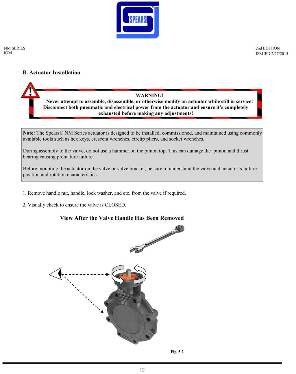
12
13


14 5. Install the actuator to the bracket. Tighten all bolts. 6. When required, mount or adjust the visual indicator as seen below. Indicator Mounting In Line Mounting Across Line Mounting Fig. 5.5 Fig
.")

15 After all mounting procedures are completed, it is necessary to set the travel stops to ensure proper rotation. The Spears travel stop allows a travel range of 100 (from +95 to -5 with 10 degrees of adjustment at open and close). If a larger range is necessary, consult your Spears representative for information on extended travel limit stops. NOTE: IMPROPER SETTING OF TRAVEL STOPS CAN REDUCE THE VALVE AND ACTUATOR'S LIFE. Limit Stop 1 Limit Stop 2 Fig. 5.7 Fig
16
17 VI. Travel Stop Adjustment Spears actuators have open and close travel stops for +5 /-5 of travel. A. Setting The Stops on Double Acting Units 1. Operate the actuator assembly to the closed position. 2. Remove/lockout the air supply to the actuator. 3. Loosen the locknut on the closed stop. 4. Turn the closed stop clockwise to reduce or counterclockwise to increase the travel. 5. Retighten the locknut. 6. Reconnect the air supply to check that the position desired is correct. If not repeat. 7. Operate the actuator assembly to the open position. 8. Remove/lockout the air supply to the actuator. 9. Loosen the locknut on the open stop. 10. Turn the top clockwise to reduce or counterclockwise to increase the travel. 11. Retighten the locknut. 12. Reconnect the air supply to check that the position desired is correct. If not repeat. items Open Limit Stop Closed Limit Stop The above illustration shows a double acting actuator in the open position and identifies the opening and closing limit stops. Fig

18 B. Setting The Stops on Spring Return Units (Fail Closed) 1. Remove the air supply to the A port. Actuator will move to the closed position. Please note the position of the actuator. 2. Apply air to open the actuator. Please note the position of the actuator in the open position. 3. While the air supply is maintained carefully loosen the locknut on the closed stop and adjust the stop to the correct position desired. 4. Retighten the locknut. 5. Remove the air supply and the actuator will go to the closed position desired. 6. If the correct position is not achieved repeat Loosen the locknut on the open stop and adjust the travel desired. (Clockwise adjustment decreases travel.) 8. Retighten the locknut. 9. Apply air and check the open position. If not correct repeat instructions 5-8. Open Limit Stop Closed Limit Stop The above illustration shows a spring return actuator (FCW configuration) in the open position and identifies the opening and closing limit stops. Fig

19 C. Setting The Stops on Spring Return Units (Fail Open) 1. Remove/lockout the air supply to the actuator and it will drive to the open position. Note the position of the actuator. 2. Apply air to close the actuator. Note the position of the actuator while the air supply is maintained, loosen the locknut on the open stop and adjust the stop to the correct position desired. 3. Retighten the locknut. 4. Remove/lockout the air supply to the actuator so that it opens, if it is not the correct position repeat items Loosen the locknut on the close stop and adjust the travel by the amount desired to give the correct position. (Clockwise adjustment decreases travel.) 6. Retighten the locknut. 7. Reapply air and check the closed position. If not desired closed position repeat items 1-5. Closed Limit Stop Open Limit Stop The above illustration shows a spring return actuator (FCCW configuration) in the open position and identifies the opening and closing limit stops. Fig


20 VII. Actuator Disassembly A. Steps to Actuator Disassembly 1. Disconnect all electrical and air supplies from the actuator. 2. Ensure the actuator is depressurized and in the fail position. 3. Remove actuator from mounting bracket and coupling, and any limit switches, manual overrides, positioners and other pneumatic accessories (where applicable), and place in a clean environment. 4. Place actuator on end and evenly loosen all end cap screws until you are able to remove the end cap. End Cap (Left) End Cap O-ring End Cap Screw Fig. 7.1 NOTE: After 4-6 turns of the end cap bolt, the springs should be decompressed. WARNING! Never attempt to assemble, disassemble, or otherwise modify an actuator while still in service! Disconnect both pneumatic and electrical power from the actuator and ensure it s completely exhausted before making any adjustments! 20

21 5. Remove any springs and repeat for the other side. Spring Cartridges Fig Loosen both limit stop nuts then remove both limit stop bolts to allow full rotation of the pinion. Stop O-rings Stop Nuts Stop Bolts Fig


22 7. Rotate the pinion counterclockwise to push the pistons away from each other until they completely disengage from the pinion. (NOTE: This is for standard FCW configuration actuators. For non-standard units rotation may be reversed. For possible actuator configurations see pg.11) 8. Remove both pistons noting their orientation so they can be replaced in the same orientation during reassembly. Pinion Piston Piston Fig Remove pinion circlip, pinion washer, and flange bearing from top of pinion. Pinion Circlip Pinion Washer Flange Bearing 22 Fig. 7.5


23 10. Slide pinion down through the bottom of the actuator until you can remove the pinion cam, thrust bearing, and upper pinion o-ring from the top of the pinion. Note the orientation of the pinion cam so it can be replaced in the same position during reassembly. Upper Pinion O-Ring Thrust Bearing Pinion Cam Pinion Bearing Lower Pinion O-ring Fig


24 VIII. Maintenance and Temperature Change A. Repair Kit Overview Anytime maintenance is preformed on an actuator, care to prevent damage to the O-rings, and bearing surfaces must be taken during the disassembly, assembly and removal or installation of actuators. During maintenance all parts should be wiped clean of grease using a clean cloth, and parts should be lubricated with the fresh grease for the correct temperature application before reassembly.below are diagrams showing the assembly of these parts and the contents of a Spears repair kit Fig. 8.2 Fig Fig. 8.1 Parts List for Spears Repair Kit Item Qty Part Material 3 1 Upper Pinion O-ring NBR* 4 1 Flange Bearing Delrin** 10 2 Piston O-ring NBR* 11 2 Piston Guide Bronze Impregnated PTFE 12 2 End Cap O-ring NBR* 17 2 Stop O-ring NBR* 16 2 Piston Skate Delrin** 20 2 Air Channel Plug NBR* 21 1 Thrust Bearing Delrin** 24 1 Lower Pinion O-ring NBR* 17 Fig Fig. 8.5 *Material will change to Viton for High temperature applications and a low temp NBR blend for low temperature *applications. **Material will change to PPSU for high temperature applications. 24
25 B. Installing Repair Kit or Changing Temperature Rating Follow the listed steps to install a repair kit or change temperature applications. For reference the various temperature specifications and materials can be found on pg. 9 of this manual. 1. Disassemble actuator as described in on pg Remove the O-rings and bearings from the various actuator components: (See fig on the previous page for list of parts to be replaced and their locations) a. Piston O-rings (2) b. End Caps (2) c. Upper Pinion O-ring (1) d. Lower Pinion O-ring (1) e. Air Passage Plugs (2) f. Stop O-rings (2) g. Pinion Bearing (1) h. Thrust bearing (1) i. Flange Washer (1) 3. Using mineral spirits (or other mild solvent), remove the lubrication from each actuator component. (Note: clean all surfaces thoroughly prior to installation of new O-ring set.) 4. Separate O-rings and determine the locations for installation: a. Piston O-rings: will be the thickest O-rings (2 pieces), (#10 fig. 8.2) b. End Cap O-rings: will have the largest O-ring diameter (2 pieces), (#12 fig. 8.3) c. Pinion O-rings: of the remaining O-rings, the largest is installed in the lower pinion O-ring groove (#24 fig. 8.1). The second largest is installed on the top of the pinion (#3 fig. 8.1). d. Air Channel Plugs: the small cylinders fit in the ends of the body (2 pieces), (#20 fig. 8.5). e. Stop O-rings: will have the smallest O-ring diameter (#17 fig. 8.4). (Note: if these O-rings are not properly seated, they may be pinched during reassembly and subsequently leak.) 5. Identify bearing parts and their installation locations: a. Piston Skates (#16 fig. 8.2) b. Thrust Bearing (#5 fig. 8.1) c. Flange Bearing (#4 fig. 8.4) 6. Apply light grease to the internal portions of the actuator for ease of reassembly: a. Inner bore of actuator. b. Piston wear surfaces (piston skate, piston bearing & piston O-Ring). c. Piston rack (apply on the full length of the piston rack). d. Pinion gear teeth. e. Pinion wear surfaces and O-rings (both upper and lower areas). 7. Assemble actuator as described on pg If the O-rings are difficult to install, the O-rings may be slightly stretched and lubricated to ease installation. (Note: be sure to use the lubricant provided when lubricating the O-rings.) When installing the end cap O-rings, be sure to seat the O-ring properly, a thin layer of grease will help hold the O-ring in place. 25

 c. Body: Insert the thrust bearing into the top pinion hole as shown. (Fig 9.")
 lubricate the inside of the cylinder, all o-rings, piston skates,")

 then slide the pinion the rest of the way through the body until it stops. (see pg.11 for more information about possible configurations). Fig. 9.2 Fig. 9.3 Fig.")

26 IX. Actuator Assembly A. Steps to Actuator Assembly The directions below assume the actuator has been disassembled. Please refer to pg. 21 if this process has not been completed. 1. Inspect all wear surfaces for excessive wear or possible damage. 2. Install all bearings and o-rings as follows: Please refer to pg.25 for available kits): a. Pinion: Install lower pinion bearing and lower pinion o-ring. (Fig. 9.1) b. Pistons: On each piston install the bearing, o-ring, and skate. (Fig. 9.2) c. Body: Insert the thrust bearing into the top pinion hole as shown. (Fig 9.3) Installed Piston O-ring Actuator Body Installed Thrust Bearing Installed lower pinion bearing Installed lower pinion o-ring Fig. 9.1 Installed Piston Bearing Piston Skate 3. Using the correct grease, (consult your Spears representative for your specific temperature application) lubricate the inside of the cylinder, all o-rings, piston skates, piston and pinion guides. The teeth of the racks and pinion should be greased so that the grooves between teeth are roughly half filled with grease while all previously mentioned surfaces should be lightly coated. 4. Slide the top half of the pinion into the bottom of the actuator, orient the cam on top of the pinion according to desired operating direction (see Fig 9.4 and 9.5 below) then slide the pinion the rest of the way through the body until it stops. (see pg.11 for more information about possible configurations). Fig. 9.2 Fig. 9.3 Fig. 9.4 Fig. 9.5 Both illustrations above show standard orientation of the cam/pinion at the actuator fail position (the pinion cam has been colored blue for contrast). In fig. 9.4 the cam configuration shown is intended for fail closed applications. In Fig. 9.5 the configuration shown is intended for fail open applications. It is important to note that the above cutaway view assumes that the stops and air ports of the actuator are facing the viewer. Once installed, look down the bore of the actuator and ensure that the cam is aligned properly with both the top of the pinion and the pinion drive in both the closed and open positions. 26


 closed position.")

27 Pinion Washer Upper Pinion O-ring Flange Bearing Pinion Circlip Fig. 9.6 Fig Press the top pinion o-ring into the inset around the top of the pinion then install the flange bearing and top pinion washer (Fig. 9.6). Use a pair of circlip pliers to install the pinion circlip (Fig. 9.7) Be careful not to expand the circlip too much as it may be damaged if over expanded. 6. Assemble the actuator stop screws by threading the stop nut onto the stop bolt and fitting the stop o-ring into the groove on the stop nut. 7. Using the proper sized crescent wrench on the pinion, rotate the pinion to the (actuator) closed position. Check the cam to make sure of correct orientation before threading in the closed limit stop until it touches the pinion cam. Tighten the locknut to secure the stop in place. This will ensure that the cam remains in the correct orientation during the installation process. Stop O-ring Stop Nut Stop Bolt Fig. 9.8 Fig
 9. Check closed position.")
28 2 8. Rotate the pinion to the open position. Orient the pistons correctly according to your operation type and slide them into the body until both racks engage with the pinion. (For correct orientation of pistons refer to p.34 of this manual) 9. Check closed position. Likely, the actuator will stop before the closed position either because of uneven engagement of the racks or because of improper orientation of the pinion. In either case, turn the actuator on end and while applying light but firm pressure to the top piston rotate the pinion so that it slowly backs the pistons out of the actuator until you feel the pinion skip a tooth. Apply even pressure to both pistons and recheck closing position. Max over travel at close (closed stop disengaged) should be roughly 5 degrees. Repeat until the actuator operates correctly. Before proceeding use the checklist below entitled Piston Calibration Checklist to ensure correct operation of the actuator. If the answer to any question below is no, disengage the pinion from the pistons and repeat from step 8. Piston Calibration Checklist To ensure pistons are aligned correctly check the following -Closed position: Does the actuator close with the pinion correctly aligned? -Travel: Does the actuator travel a full 90? -Open position: At fully opened position is the pinion aligned correctly? -Pistons: Fig At fully opened position is the air inlet blocked? (See Below) Are both pistons equal distances inside the body? The arrow in both illustrations above points to the air inlet while the actuator is in the fully open position. In the illustration on the left the air inlet is unobstructed and the actuator will function normally. In the illustration on the right the inlet is obstructed and the pistons need to be realigned. 28


29 10. After you have ensured the pistons are correctly installed in the actuator, move the actuator to the open position, set the open stop the same way as the closing stop in step 8, then close the actuator. Fig Fig At this point, if the actuator is a spring return type, install any springs that are to be used. See pg. 32 for correct spring configurations and designations. If the actuator is double acting, proceed to the next step. Spring Cartridge Fig
 to evenly seat the end cap onto the actuator, then repeat this for the opposing end cap. Fig. 9.14 13.")
30 12. After ensuring the end cap O-ring is in place and lubricated, place the end cap on the actuator and tighten it using the end cap screws. Tighten the screws incrementally in the pattern shown below (Fig. 9.14) to evenly seat the end cap onto the actuator, then repeat this for the opposing end cap. Fig Once assembled, the actuator must be tested as outlined on pg. 33 before returning to service. 30
 refers to an actuator without springs, the letter K followed by the number of springs in each end cap is used for the different spring configurations.")

31 B. Spring Configurations The Spears NM series actuator uses fully encapsulated, preloaded spring cartridges that are easily configured for adjustable spring return torque. While DA (double acting) refers to an actuator without springs, the letter K followed by the number of springs in each end cap is used for the different spring configurations. Below are the proper spring configurations as seen from the back of a piston. Thus, a K11, K22, and K33 actuator will have 1, 2, and 3 springs per piston (i.e. 2, 4, and 6 springs per actuator) respectively. Note the dotted outline of the rack on the left side of the piston illustrations below. The rack location determines orientation of the springs, and the configurations below allow for the most efficient use of the spring force as well as balancing it across the face of the pistons. Doing this both increases the efficiency and the life of the Spears actuator. K11 K22 K K44 K55 K

. Any air leaks will be indicated with the soap bubbling. 3. In case of leakage around: a.")

32 C. Air Leak Test Any time the actuator is modified or undergoes maintenance, a leak test needs to be completed to insure the actuator is air tight and working correctly. To perform an air leak test: 1. Use a soap and water mixture to coat the actuator at the designated points below: a. Around the base of the pinion neck (1). b. Around the base of the stops (2). c. Endcaps (3) d. The pinion base (4) Port B Port A Fig Fig Apply air pressure to ports A and B (max 8bar/120psi). Any air leaks will be indicated with the soap bubbling. 3. In case of leakage around: a. The limit stop bolts: check for o-ring damage, if none is found, turn the lock nut tighter until it no longer leaks. b. The endcaps: Disassemble the endcaps and check the o-ring for damage, if none is found ensure the endcaps are properly seated and tightened. c. The pinion top or bottom disassemble the actuator, replace the o-rings and reassemble. 32
, and set the new closed stop. 3.")

33 D. Changing Fail Configurations Follow these steps to change the fail configuration of the actuator: 1. Disassemble the actuator as described on pg.21 steps Using the proper size crescent wrench, rotate the pinion to its new orientation when in the fail position (actuator closed), and set the new closed stop. 3. Check the cam to make sure the flat side of the cam is making contact with the stop. 4. Rotate the pinion to the new open position. 5. Rotate the pistons 180 degrees from their original orientation and insert them into the actuator. 6. Finish assembling the actuator as described on pg. 29 starting at step 10. FCW Closed Limit Stop FCCW Closed Limit Stop Fig Fig Fig Fig The illustrations above show the fail orientation of the pinion for the FCW configuration (Fig. 9.18) and the FCCW configuration (Fig. 9.19) as described in step 2 above. Also shown above is the correct location for the closed limit stops for each configuration. Figs illustrate adjustments that must be made when going from FCCW to FCW (Fig. 9.20) or when going from FCW to FCCW (Fig. 9.21). Note pinion has been rotated to its new opening position and the pistons have been rotated 180 from their original position before being inserted into the body. 33
34 XI. Series Torque Information NOTE: For help with sizing contact Spears Manufacturing Company. A. B. Size Size Spring Designation NM Series Double Acting Torques (in-lbs) Air Supply Pressure 30PSI 40PSI 50PSI 60PSI 70PSI 80PSI 90PSI 100PSI 110PSI 120PSI NM Series Spring Return Torques (in-lbs) Actuator Air Torques 40PSI 60PSI 80PSI 100PSI 120PSI Actuator Spring Torques Start End Start End Start End Start End Start End Start End K K K K K K K K K K K K K K K K K K
35 Size Spring Designation NM Series Spring Return Torques (in-lbs) Actuator Air Torques 40PSI 60PSI 80PSI 100PSI 120PSI Actuator Spring Torques Start End Start End Start End Start End Start End Start End K K K K K K K K K K K K K K K K K K K K K K K K K K K K K K K K K K K K K K K K K K K K K K K K
36 Size Spring Designation NM Series Spring Return Torques (in-lbs) Actuator Air Torques 40PSI 60PSI 80PSI 100PSI 120PSI Actuator Spring Torques Start End Start End Start End Start End Start End Start End K K K K K K K K K K K K K K K K K K
 NM 20 5.79 3.15 2.80 3.62 2.83 0.79 (20mm) 1.417 (F03)* #10-32 UNF* 1.969 (F05)* 1/4-20 UNC* 3.15-0.59 2.09 1.61 0.433 (11mm) NM 34 6.69 3.50 3.30 4.24 3.46 0.79 (20mm) 1.969 (F05) 1/4-20 UNC 2.")
 1.969 (F05) 1/4-20 UNC 2.756 (F07) 5/16-18 UNC 3.15 3.88 0.94 3.07 2.25 0.669 (17mm) NM105 10.43 4.72 4.27 5.38 4.59 0.79 (20mm) 1.969 (F05) 1/4-20 UNC 2.756 (F07) 5/16-18 UNC 3.15 4.")
37 XII. Dimensional Information ** SIZE L W1 W2 H1 H2 P BC1 T1 BC2 T2 A B C D E F NM (20mm) (F03) #10-32 UNF (F05) 1/4-20 UNC (11mm) NM (20mm) (F03)* #10-32 UNF* (F05)* 1/4-20 UNC* (11mm) NM (20mm) (F05) 1/4-20 UNC (F07) 5/16-18 UNC (14mm) NM (20mm) (F05) 1/4-20 UNC (F07) 5/16-18 UNC (14mm) NM (20mm) (F05) 1/4-20 UNC (F07) 5/16-18 UNC (17mm) NM (20mm) (F05) 1/4-20 UNC (F07) 5/16-18 UNC (17mm) NM (20mm) (F07) 5/16-18 UNC (F10) 3/8-16 UNC (22mm) NM (30mm) (F07) 5/16-18 UNC (F10) 3/8-16 UNC 3.15/5.12** (22mm) NM (30mm) (F10) 3/8-16 UNC (F12) 1/2-13 UNC 3.15/5.12** (22mm) NM (30mm) (F10) 3/8-16 UNC (F12) 1/2-13 UNC 3.15/5.12** (27mm) NM (30mm) (F10) 3/8-16 UNC (F12) 1/2-13 UNC 3.15/5.12** (27mm) NM (30mm) (F14) 5/8-11 UNC (36mm) NM (30mm) (F14) 5/8-11 UNC (36mm) NM (30mm) (F16) 3/4-10 UNC (46mm) NM (30mm) (F16) 3/4-10 UNC (46mm) *The size 20 is also available with an F04 (#10-32 UNF on a B.C.) mounting pattern in place of the F03/F05. **Sizes have 3.15 x 1.18 and a 5.12 x 1.18 top mounting with (8) M5 x 0.8 threaded holes. 37
38 WA R R A N T Y THE SELLER WARRANTS ITS PRODUCTS AGAINST DEFECTS IN MATERIALS OR WORKMANKSHIP, WHEN USED ON THOSE SERVICES APPROVED BY THE SELLER, FOR A PERIOD OF TWO YEARS FROM THE DATE OF ORIGINAL SHIPMENT. THE SELLER S LIABILITY UNDER THIS WARRANTY SHALL BE LIMITED TO REPAIR OR REPLACEMENT AT SELLER S OPTION OF SUCH PRODUCTS. F.O.B. FACTORY, UPON PROOF OF DEFECTS SATISFACTORY TO SELLER. SELLER MAKES NO WARRANTIES, EITHER EXPRESSED OR IMPLIED, EXCEPT AS PROVIDED HEREIN, INCLUDING WITHOUT LIMITATION THEREOF, WARRANTIES AS TO MARKETABILITY, MERCHANTABILITY, FITNESS FOR A PARTICULAR PURPOSE OR USE, OR AGAINST INFRINGMENT OF ANY PATENT. IN NO EVENT SHALL SELLER BE LIABLE FOR ANY DIRECT, INCIDENTAL OR CONSEQUENTIAL DAMAGES OF ANY NATURE, OR LOSES OR EXPENSES RESULTING FROM ANY DEFECTIVE PRODUCTS OR THE USE OF ANY PRODUCT. For questions or more information, visit Spears Manufacturing Company P.O. Box 9203, Olden St., Sylmar, CA Telephone: Fax:
Installation, Operation, and Maintenance Manual for Milwaukee Valve
 Installation, Operation, and Maintenance Manual for Milwaukee Valve RACK AND PINION PNEUMATIC ACTUATORS TABLE OF CONTENTS I. Introduction... 04 A. Storage... Pg.04 II. Identification... 05 A. General Identification...
Installation, Operation, and Maintenance Manual for the Contromatics M6 Series RACK AND PINION PNEUMATIC ACTUATORS
 Installation, Operation, and Maintenance Manual for the Contromatics M6 Series RACK AND PINION PNEUMATIC ACTUATORS 6 th Edition TABLE OF CONTENTS I. Introduction.... 04 A. Storage...Pg.04 II. Identification....
Pneumatic Actuator PIK Series
 Pneumatic Actuator PIK Series Engineering Creative Solutions for Fluid Systems Since 1901 INTRODUCTION Pratt Industrial designs and provides high quality actuators and services related to valve automation.
UNITORQ "M" SERIES RACK AND PINION PNEUMATIC ACTUATORS INSTALLATION OPERATION & MAINTENANCE
 UNITORQ "M" SERIES RACK AND PINION PNEUMATIC ACTUATORS INSTALLATION OPERATION & MAINTENANCE MANUAL 5TH EDITION TABLE OF CONTENTS 1-1 INTRODUCTION... 2 2-1 STORAGE... 2 3-1 OPERATING CHARACTERISTICS SPRING
INSTALLATION, OPERATION & MAINTENANCE MANUAL
 Rack & Pinion Pneumatic Actuators INSTALLATION, OPERATION & MAINTENANCE MANUAL QSM, Inc. 127 Village Lane Easley, SC 29642 U.S.A. Ph: (864) 605-0150 Fax: (864) 605-0830 www.tru-flo.com TABLE OF CONTENTS
AV INSTALLATION, OPERATION & MAINTENANCE MANUAL
 Rack & Pinion Pneumatic Actuators AV INSTALLATION, OPERATION & MAINTENANCE MANUAL AVCS PO Box 68172 Minneapolis, MN 55418 TABLE OF CONTENTS CHAPTER 1: PRODUCT DESCRIPTION 3 CHAPTER 2: TECHNICAL FEATURES
DelTorq Series 21 ACTUATOR
 Jamieson Equipment Company DelTorq Series 21 ACTUATOR INSTALLATION, OPERATION AND MAINTENANCE MANUAL ENGINEERING DATA SHEET E.D.S. NO EDS055 ISSUE DATE - -- 20/01/2007 (Please read the entire instructions
Flow Line Controls. Installation & Operations Manual SERIES 20/21 Pneumatic Actuators
 Flow Line Controls Installation & Operations Manual SERIES 20/21 Pneumatic Actuators Flow Line Controls, Inc. P.O. Box 677 Schriever, LA 70395 Phone: 985-414-6003 Toll Free 1-800-815-9226 Fax 985-414-6072
DelTech Controls L.L.C.
 DelTech Controls L.L.C. DelTorq Series 20 ACTUATORS TECHNICAL DATA SHEET T.D.S. NO. 20 105 / R1 ISSUE DATE : NOV 2004 INSTALLATION, OPERATION AND MAINTENANCE MANUAL Guarantee : ( Please read the entire
aero 2 -IOM aero 2 ACTUATOR - INSTALLATION, OPERATION & MAINTENANCE MANUAL
 Instruction DP00226 May 2015 IMPORTANT SAFETY WARNINGS A. Before carrying out any repair or maintenance on the actuator, make sure that the pressure supply lines and electrical connections have been safely
Easytork Vane Actuator IOM
 Easytork Vane Actuator IOM General Storage The Easytork Vane Actuator ( EVA ) is a high-quality product and as such must be handled, transported and stored with care. Prior to storage, inspect the actuator
Installation and Maintenance Instructions for Grinnell GRP Pneumatic Rack and Pinion Actuators
 FLOW CONTROL for Introduction The Grinnell GRP Pneumatic Actuator is a compact, rack & pinion design, conforming to Grinnell standard or direct mount standards or EN ISO 5211 mounting configuration, depending
Removing the Actuator for Valve Repair IMPORTANT! READ THIS BEFORE PROCEEDING!
 SVF Flow Controls Inc. Maintenance Manual - CleanFLOW Removing the Actuator for Valve Repair IMPORTANT! READ THIS BEFORE PROCEEDING! Before proceeding with the removal of an actuator from a valve it is
C Series Pneumatic Rack & Pinion Rotary Actuators
 Allied Flow Controls, Inc. C Series Pneumatic Rack & Pinion Rotary Actuators Spring Return & Double Acting Features and Benefits Torque Range at 0 Psig Air Pressure: Double Acting: -,00 lbf-in Spring Return:
UT SERIES PNEUMATIC ROTARY ACTUATORS
 UT SERIES PNEUMATIC ROTARY ACTUATORS Toll Free 1.888.842.9998 Fax 1.866.842.3144 6 FEATURES COMPACT DESIGN The MAX-AIR rack & pinion pneumatic actuator produces linear torque output in a compact design
MTC Series. Double Acting and Spring Return Actuator and Accessories. MasterTorq. Pneumatic Actuators. Atex Class 2
 Double Acting and Spring Return Actuator and Accessories MTC Series TM Pneumatic Actuators Atex Class Operations Double Acting A B A B By supplying air to Port A, pressure is applied to the center chamber
Pneumatic Rack & Pinion Actuator
 Pneumatic Rack & Pinion Actuator 4120 N.E. Columbia Blvd. Portland Oregon USA 97211 Phone: 503-287-8383 Fax: 503-281-9677 www.fnwvalve.com STANDARD FEATURES Torque output range from 40 to 32,315 inch-pounds
Spring Return and Double Acting Pneumatic Quarter-turn Actuators Operations Manual
 Spring Return and Double Acting Pneumatic Quarter-turn Actuators Operations Manual Table of Contents General..................... 1 Pneumatic Recommendations... 1 Construction................. 2 Disassembly
IOM Manual. IOM Manual. Series 20/21.
 IOM Manual IOM Manual Series 20/21 www.flowlinevalves.com Flow Line Valve and Controls, L.L.C. 110 Main Project Road Schriever, LA 70395 P.O. Box 677 Schriever, LA 70395 Phone 985-414-6004 * Toll Free
KF Contromatics Series PA/PAS M5 Pneumatic Actuators
 The KF Contromatics M5 series rack-and-pinion actuator is the most versatile unit available today. All are rated for 150 PSIG inlet pressure and offer the DLS feature of double limit stops as standard
MT SERIES PNEUMATIC ROTARY ACTUATORS
 MT SERIES PNEUMATIC ROTARY ACTUATORS Toll Free 1.888.842.9998 Fax 1.866.842.3144 6 FEATURES COMPACT DESIGN The MAX-AIR rack & pinion pneumatic actuator produces linear torque output in a compact design
CVS Rack and Pinion Pneumatic Actuator
 Instruction Manual CVS Rack and Pinion Pneumatic Actuator Introduction These instructions apply specifically to the CVS Rack and Pinion pneumatic actuator. This manual provides sizing, maintenance, operation,
Installation and Maintenance Instructions for Morin MRP Pneumatic Rack and Pinion Actuators
 for Morin MRP Pneumatic Rack and Pinion Actuators Introduction The Morin MRP Pneumatic Actuator is a compact, rack & pinion design, conforming to Keystone standard or direct mount standards or EN ISO 5211
SPN II. S h a r p e T o l l Free (877) F a x (708)
 F a x (708)") SPN II S h a r p e T o l l Free (877) 774-2773 F a x (708) 562-9250 www.sharpevalves.com 1 SPN II Pneumatic Actuator Rack & pinion design The standard actuator configuration has hard anodized aluminum
SPN II S h a r p e T o l l Free (877) 774-2773 F a x (708) 562-9250 www.sharpevalves.com 1 SPN II Pneumatic Actuator Rack & pinion design The standard actuator configuration has hard anodized aluminum
RACK & PINION ACTUATORS 2R40 to 2R1750 Series Installation & Maintenance Manual
 TRIAC 2R Series Actuators: Attention: Instructional videos on some of the information provided below can be found on our website (http://www.a-tcontrols.com/videos/). Description Section Installation of
Double Acting & Spring Return. SERIES 92/93 Rack & Pinion PNEUMATIC ACTUATOR. The High Performance Company
 PNEUMATIC ACTUATOR SERIES 92/93 Rack & Pinion Double Acting & Spring Return The High Performance Company SERIES 92/93 Styling, strength, compactness, and simplicity of design have been combined to produce
ACM SERIES Pneumatic Actuators
 ACM SERIES Pneumatic Actuators ATEX ACHEM Controls Add: North Service Road #., Oakville, Ontario Canada Phone: --34 Cell: 0--004 E-mail: Kevin.armstrong@achemgroup.com www.achemgroup.com Skype: achemkevin
BR 31a Rack-and-pinion Actuator,
 Operating, assembly and maintenance instructions BR 31a Rack-and-pinion Actuator, SRP and DAP 1. General These instructions are intended to support the user in the assembly, maintenance, and repair of
KEYSTONE FIGURE 79 PNEUMATIC ACTUATOR OPERATING AND MAINTENANCE INSTRUCTIONS
 Operating and Maintenance Instructions for: Figure 79 Pneumatic Actuators (U/E options) Double Acting Actuator 4. If pipelines are hydraulically tested, then the lines should be blown down with high pressure
SPN II Pneumatic Actuator
 SPN II Pneumatic Actuator Rack & pinion design The standard actuator configuration has an epoxy coated, hard anodized aluminum body and epoxy coated end caps Inside surface finish (Ra 0.4-0.6µm) to minimize
I&M UT Series (2003 Design)
") I&M UT Series (2003 Design) 3170 Wasson Road Cincinnati, OH 45209 USA Phone 513-533-7340 ax 513-533-7343 E-Mail: marwin@richardsind.com www.marwinvalve.com Installation & Maintenance Instructions for Marwin
I&M UT Series (2003 Design) 3170 Wasson Road Cincinnati, OH 45209 USA Phone 513-533-7340 ax 513-533-7343 E-Mail: marwin@richardsind.com www.marwinvalve.com Installation & Maintenance Instructions for Marwin
Operating and Maintenance Instructions for: Figure 79 Pneumatic Actuators (U/E options)
") for: Figure 79 Pneumatic Actuators (U/E options) Introduction The Keystone Figure 79 Pneumatic Actuator range is available in three mounting options, as follows:- 79U - Keystone Mounting Standard 79E -
for: Figure 79 Pneumatic Actuators (U/E options) Introduction The Keystone Figure 79 Pneumatic Actuator range is available in three mounting options, as follows:- 79U - Keystone Mounting Standard 79E -
I & M UT Series (2003 Design)
") I & UT Series (003 Design) 3170 Wasson Road Cincinnati, OH 4509 USA Phone 513-533-5600 Fax 513-871-0105 marwin@richardsind.com www.marwinvalve.com Installation & aintenance Instructions for arwin UT Series
I & UT Series (003 Design) 3170 Wasson Road Cincinnati, OH 4509 USA Phone 513-533-5600 Fax 513-871-0105 marwin@richardsind.com www.marwinvalve.com Installation & aintenance Instructions for arwin UT Series
INSTRUCTION MANUAL INSTALLING NEW GREASE IN UT SERIES PNEUMATIC ACTUATOR
 INSTRUCTION MANUAL INSTALLING NEW GREASE IN UT SERIES PNEUMATIC ACTUATOR This instruction manual explains the steps required to degrease and install new grease into the Max-Air UT series pneumatic actuator.
AVK SERIES 41 SWING CHECK VALVE FIELD MAINTENANCE AND INSTRUCTION MANUAL FOR SWING CHECK VALVES 3" - 12"
 AMERICAN AVK COMPANY AVK SERIES 41 SWING CHECK VALVE FIELD MAINTENANCE AND INSTRUCTION MANUAL FOR SWING CHECK VALVES 3" - 12" TABLE OF CONTENTS EXPLODED ASSEMBLY / PARTS LIST INTRODUCTION / DESCRIPTION
Figure RP ACTUATORS PNEUMATIC RACK & PINION.
 Figure RP ACTUATORS PNEUMATIC RACK & PINION www.fnw.com TORQUE RANGES The RP rack and pinion actuators are available with output torques ranging from 44 to 36,269 in-lbs depending on air supply pressure
Pneumatic actuator. Inspired By Challenge
 Inspired By Challenge Actuation COMPACT actuator ESD system Interfaces Ordering code system Introduction Proven advantage The COMPACT actuator is a quarter-turn rack & pinion pneumatic actuator that doubles
THD-SERIES S11DA280 THRU S27DA1020 & S11SR280 THRU S27SR1020 DOUBLE ACTING & SPRING RETURN SCOTCH YOKE ACTUATORS
 THD-SERIES S11DA280 THRU S27DA1020 & S11SR280 THRU S27SR1020 DOUBLE ACTING & SPRING RETURN SCOTCH YOKE ACTUATORS INTRODUCTION A-T Controls THD scotch yoke actuators have been designed and engineered to
AVK SERIES 41 SWING CHECK VALVE FIELD MAINTENANCE AND INSTRUCTION MANUAL FOR SWING CHECK VALVES 3" - 12"
 AMERICAN AVK COMPANY AVK SERIES 41 SWING CHECK VALVE FIELD MAINTENANCE AND INSTRUCTION MANUAL FOR SWING CHECK VALVES 3" - 12" TABLE OF CONTENTS EXPLODED ASSEMBLY / PARTS LIST INTRODUCTION / DESCRIPTION
BULLTIN B PISTON ACTUATOR. The Actuator that Delivers Maximum Torque for Minimum Air Consumption
 BULLTIN B60 PISTON ACTUATOR The Actuator that Delivers Maximum Torque for Minimum Air Consumption TABLE OF CONTENTS: COMPACT DESIGN PRINCIPLE OF OPERATION PARTS LIST MAIN FEATURES TORQUEMETRIC TORQUEIMPERIAL
Pneumatic actuator. Inspired By Challenge
 Inspired By Challenge Actuation COMPACT actuator ESD system Interfaces Ordering code system Introduction Proven advantage The COMPACT actuator is a quarter-turn rack & pinion pneumatic actuator that doubles
PNEUMATIC QUARTER TURN RACK & PINION ACTUATOR MODEL - HP
 FEATURES AND BENEFITS Aluminium body, hard anodized, internally polished to 45-50µ and Nickel plated to protect against wear and corrosion Open/Closed indicator is standard on all models Travel adjustment
brochure PN
 brochure PN-2013-01 www.bitorq.com/pneumatic.html Pneumatic Actuators PAGES 4-11 ON THE WEB AT BITORQ.COM/PNEUMATIC_PN.HTML COMPACT, RELIABLE DESIGN OPEN-CLOSED ADJUSTMENT STOPS DOUBLE ACTING AND SPRING
Z-Tech Severe Chemical Service Valves We Put Control Where You Need It.
 Z-Tech Severe Chemical Service Valves We Put Control Where You Need It. Z-Tech Series Valves TABLE OF CONTENTS Ball Valves ZT 4 Series: Three Piece Flanged Ball Valve... -3 Pneumatic Actuators and Accessories...
VALV-POWR VALUE-LINE DOUBLE-OPPOSED PISTON ACTUATORS MODEL A. Installation, Maintenance and Operating Instructions
 VALV-POWR VALUE-LINE DOUBLE-OPPOSED PISTON ACTUATORS MODEL A Installation, Maintenance and Operating Instructions IMO-529 EN /208 2 IMO-529 EN TABLE OF CONTENTS. GENERAL... 3 2. TECHNICAL DATA... 3 3.
INLINE supplies a range of pneumatic 1/4 turn, RACK and PINION TYPE rotary actuators, in double-acting and spring return versions.
 Note: The parts referred to by the numbers in parentheses are shown on page 3 of this instruction manual INLINE supplies a range of pneumatic / turn, RACK and PINION TYPE rotary actuators, in double-acting
UT Series. Pneumatic Actuators. UT-**-DA Series UT-**-SR Series. A full range of double acting and spring return actuators designed
 UT-**-DA Series UT-**-SR Series A full range of double acting and spring return actuators designed to NAMUR for air supply ports and top mounting with ISO 5211 for base mounting patterns. Features Dual
SERIES 15 PNEUMATIC ACTUATOR CONTENT PNEUMATIC ACTUATOR ZT SERIES PNEUMATIC ACTUATOR... 1 AW SERIES PNEUMATIC ACTUATOR...
 CONTENT... 1-27 ZT SERIES... 1 AW SERIES... 19 reserves the right to change specifications without notice. i ZT SERIES INTRODUCTION The ZT series pneumatic actuator is one of the best designs in the market,
Revo Actuators Pneumatic Rack and Pinion
 Revo Actuators Pneumatic Rack and Pinion Design Features & Benefits Revo Pneumatic Actuators 1) Standardized actuator to valve interface per DIN ISO 5211 (not visible) 2) Standardized accessory interfaces
Fisher 1061 Pneumatic Piston Rotary Actuator with Style H & J Mounting Adaptations
 Instruction Manual 1061 H & J Actuator Fisher 1061 Pneumatic Piston Rotary Actuator with Style H & J Mounting Adaptations Contents Introduction... 1 Scope of Manual... 1 Description... 2 Specifications...
VALV-POWR SERIES VPVL MODEL D DOUBLE-ACTING AND SPRING-RETURN RACK- AND-PINION COMPACT PNEUMATIC ACTUATORS
 VALV-POWR SERIES VPVL MODEL D DOUBLE-ACTING AND SPRING-RETURN RACK- AND-PINION COMPACT PNEUMATIC ACTUATORS The Jamesbury Valv-Powr VPVL double-opposed piston actuators combine the benefits of high cycle
Pneumatic Actuators. 1. DIE CAST ALUMINUM END CAPS: standard polyester powder coated
 4 5 Pneumatic s 1 2 6 NOMINAL VALUES: Pressure rating max 115 PSI Temperature range: standard (-4 F;+185 F), high (-4 F;+302 F), low (-40 F;+185 F) Pre lubricated for life of actuator at assembly 100%
SY-SERIES S04DA75 THRU S06DA180 & S04SR75 THRU S06SR180 DOUBLE ACTING & SPRING RETURN SCOTCH YOKE ACTUATORS
 SY-SERIES S04DA75 THRU S06DA180 & S04SR75 THRU S06SR180 DOUBLE ACTING & SPRING RETURN SCOTCH YOKE ACTUATORS INTRODUCTION A-T Controls SY scotch yoke actuators have been designed and engineered to provide
radius Series A pneumatic rack & pinion actuators
 radius Series A pneumatic rack & pinion actuators EVOLUTION IN ENGINEERING The Series A double acting and spring return pneumatic rack and pinion actuators from Radius offer uncompromising standards of
radius Series A pneumatic rack & pinion actuators
 radius Series A pneumatic rack & pinion actuators EVOLUTION IN ENGINEERING Seals: Buna-N Nitrile is standard. Optional materials are available. The Series A double acting and valve and damper applications.
Keystone F89 pneumatic quarter-turn actuator General purpose / hazardous area
 Compact, reliable and low operation costs for all types of quarter-turn valves are the keywords of the Keystone F89 range of pneumatic actuators Features Direct mounting to all Keystone butterfly valves
KEYSTONE F89 pneumatic quarter-turn actuator GENERAL PURPOSE / HAZARDOUS AREA
 compact, reliable and low operation costs for all types of quarter-turn valves are the keywords of the Keystone F89 range of pneumatic actuators FEATURES Direct mounting to all Keystone butterfly valves
MAINTENANCE INSTRUCTIONS
 MAINTENANCE INSTRUCTIONS Direct Mount Pneumatic Actuators Double-Acting and Spring-Return Installation, Service and Operation Sizes 0052 through 0125 COMPONENT LIST Item Description 1 Housing 2 Pinion
AMERICAN AVK COMPANY AVK SERIES 24 - HIGH PRESSURE, WET BARREL HYDRANT FIELD MAINTENANCE AND INSTRUCTION MANUAL TABLE OF CONTENTS
 AMERICAN AVK COMPANY AVK SERIES 24 - HIGH PRESSURE, WET BARREL HYDRANT FIELD MAINTENANCE AND INSTRUCTION MANUAL TABLE OF CONTENTS EXPLODED ASSEMBLY / PARTS LIST INTRODUCTION / DESCRIPTION RECEIVING AND
Valtek Auxiliary Handwheels and Limit Stops
 Valtek Auxiliary s and Limit Stops Table of Contents Page 1 General information 2 Installation 2 Side-mounted handwheels, size 25 and 50 (linear actuators) 3 Side-mounted handwheels, size 100 and 200 (linear
+Actuators GEMELS PNEUMATIC ACTUATORS. Actuators. INSTALLATION, OPERATION AND MAINTENANCE TECHNICAL DETAILS Quarter-Turn Rack & Pinion
 +Actuators + GEMELS PNEUMATIC ACTUATORS INSTALLATION, OPERATION AND MAINTENANCE TECHNICAL DETAILS Quarter-Turn Rack & Pinion Actuators + Actuators Specialist in Ball Valves Introduction STANDARDS Gemels
KF Contromatics Series PA/PASM5 Pneumatic Actuators
 KF Contromatics Series PA/PASM5 Pneumatic Actuators Superior Fluid Control Products KF Contromatics Series PA/PAS M5 Pneumatic Actuators The KF Contromatics M5 series rack-and-pinion actuator is the most
Pneumatic Actuators & Accessories. Actuator Dimensions. Torque Charts, Double Acting & Spring Return
 DESCRIPTION Pneumatic Actuators & Accessories Design Features Actuator Dimensions Torque Charts, Double Acting & Spring Return Actuator Weights, Air Volumes & Actuator Cycle Time Installation & Operating
Bettis RPE-Series Rack and Pinion Pneumatic Actuators
 Bettis RPE-Series Rack and Pinion Pneumatic Actuators Product Data Sheet September 2017 BE.00.00 Rev. 3 High quality and economical actuator Improve plant and operator safety Riable and flexible in process
Rack & Pinion Pneumatic Actuators SPRING RETURN DOUBLE ACTING
 Rack & Pinion Pneumatic Actuators SPRING RETURN DOUBLE ACTING Proven quality since 1892 Econosto, part of the ERIKS group, has been offering a wide variety of engineered products since 1892. By focusing
SD Bendix E-10PR Retarder Control Brake Valve DESCRIPTION. OPERATION - Refer to Figure 2
 SD-03-832 Bendix E-10PR Retarder Control Brake Valve MOUNTING PLATE SUPPLY 4 PORTS ELECTRICAL AUXILIARY DESCRIPTION TREADLE RETARDER CONTROL SECTION EXHAUST DELIVERY 4 PORTS FIGURE 1 - E-10PR RETARDER
HAYWARD FLOW CONTROL TBH SERIES TRUE UNION BALL VALVE INSTALLATION, OPERATION AND MAINTENANCE INSTRUCTIONS
 HAYWARD FLOW CONTROL TBH SERIES TRUE UNION BALL VALVE INSTALLATION, OPERATION AND MAINTENANCE INSTRUCTIONS Pg. 1 of 10 PLEASE READ THE FOLLOWING INFORMATION PRIOR TO INSTALLING AND USING HAYWARD TBH SERIES
TABLE OF CONTENTS. 3 Outlet Stainless Steel Body. 3 Outlet Ductile Body. 2 Outlet Ductile Body 2 Outlet Bronze Body
 AVK SERIES 24 - HIGH PRESSURE, WET BARREL HYDRANT FIELD MAINTENANCE AND INSTRUCTION MANUAL TABLE OF CONTENTS EXPLODED ASSEMBLY / PARTS LIST INTRODUCTION / DESCRIPTION RECEIVING AND STORAGE INSTALLATION
EL-O-Matic F-Series Rack and Pinion Pneumatic Actuators
 Product Data Sheet October 2016 EF.00.00.EN Rev. 7 EL-O-Matic F-Series Rack and Pinion Pneumatic Actuators High quality and economical actuator Improve plant and operator safety Reliable and flexible in
A comprehensive range of pneumatic actuators, providing compact, reliable and economical powered operation for all types of quarter-turn valves
 KEYSTONE A comprehensive range of pneumatic actuators, providing compact, reliable and economical powered operation for all types of quarter-turn valves Features Direct mounting to all Keystone butterfly
IMO - 528EN Issue Date: 1/11
 IMO - 528EN Issue Date: / INSTALLATION, MAINTENANCE, AND OPERATING INSTRUCTIONS VALV-POWR VPVL MOD C VALUE-LINE DOUBLE-OPPOSED PISTON ACTUATORS Read entire instructions carefully before installation or
POR SERIES Pneumatic Overload Release Clutches
 POR SERIES Pneumatic Overload Release Clutches P-3030-BG Installation and Operation POR Series Model H2000 An Altra Industrial Motion Company Contents I. Operating Principle...2 Il. Ill. Mounting Adapters
OPERATION AND MAINTENANCE INSTRUCTIONS
 OPERATION AND MAINTENANCE INSTRUCTIONS 334 SERIES THREE-PIECE BALL VALVES 1/4 to 2-1/2 Installation and Operation Always install your valve according to accepted industry standards and practices and operate
MANUAL - PNEUMATIC ACTUATORS, SERIES DA & SR - 1 -
 MANUAL - PNEUMATIC ACTUATORS, SERIES DA & SR - 1 - DOUBLE ACTING ACTUATOR DA SPRING RETURN ACTUATOR SR - LCIE 05 AR 022 MANUAL - PNEUMATIC ACTUATORS, SERIES DA & SR - 2 - Content 1. Applicable Range 3
D-Series Rack & Pinion Pneumatic Actuators
 D-Series Rack & Pinion Pneumatic Actuators Introduction 2 Bettis D-Series pneumatic rack and pinion actuators provide its users with reliability and economy in valve automation. Specifically designed for
R-type, RY-type EPR-Series. Actuators for Quarter-Turn Valves
 R-type, RY-type EPR-Series Actuators for Quarter-Turn Valves >> Introduction The EPR-Series pneumatic actuator provides a rugged solution for quarter-turn actuation while reducing maintenance requirements.
CLARK SOLUTIONS 8P Series Pneumatic Actuated Ball Valves 1/4 to 4 Brass & Stainless Steel, 2-way & 3-way configurations
 CLARK SOLUTIONS 8P Series Pneumatic Actuated Ball Valves 1/4 to 4 Brass & Stainless Steel, 2-way & 3-way configurations www.clarksol.com SERIES 8P0O80/82/135/136 SERIES 8P0129/131(T,L) 80: Direct mount
IA m tion - Pneumatic actuators. Description. Product features. Design properties
 IA mtion Pneumatic actuators Description The rack and pinion pneumatic actuator IA Motion combines innovative design features with the latest technology, materials and protection coatings available, resulting
DA/SR. Pneumatic Rotary Actuators FEATURES VALBIA ISO 9001 CERTIFIED
 VALBIA ISO 9001 CERTIFIED FEATURES Twin Rack and Pinion Design Constant Torque Output Compact Design Balanced Internal Forces Robust Design For Long Life Extruded Aluminum Body Hard Coat Anodized Smooth
VALV-POWR SERIES VPVL MODEL C DOUBLE-ACTING AND SPRING-RETURN RACK- AND-PINION COMPACT PNEUMATIC ACTUATORS
 VALV-POWR SERIES VPVL MODEL C DOUBLE-ACTING AND SPRING-RETURN RACK- AND-PINION COMPACT PNEUMATIC ACTUATORS VALV-POWR VPVL double-opposed piston actuators combine the benefits of high cycle life, a rugged
PP Series Pneumatic Actuators
 PDF Published February 4, 07 PP Series Pneumatic Actuators for Chemline ball valves up to 6 MATERIAL: Polyamide SERIES: PPS Spring Return PPD Double Acting CONTROL PRESSURE: 40 to 0 psi OUTPUT TORQUES:
Industrial Turbo Meters, Sizes 2" through 6"
 Industrial Turbo Meters Sizes 2" through 6" TUR-UM-00530-EN-19 (October 2014) User Manual Industrial Turbo Meters, Sizes 2" through 6" User Manual CONTENTS Scope of the Manual 5 Specifications 5 Product
Pneumatic Actuators Quarter Turn Rack & Pinion Double Acting and Spring Return
 Pneumatic Actuators Quarter Turn Rack & Pinion Double Acting and Spring Return SERIES Features Rack and pinion quarter turn (90 ) rotation Double acting and spring return models Prelubricated and tested
Bettis RPE-Series Rack and Pinion Pneumatic Actuators
 Rack and Pinion Pneumatic Actuators BE.00.00 Rev. 7 March 2019 High quality and economical actuator Improve plant and operator safety Reliable and flexible in process control Increase serviceability BEG.01.00.EN,
Pneumatic Rack & Pinion AC-SERIES ACTUATOR
 Pneumatic Rack & Pinion AC-SERIES ACTUATOR TABLE OF CONTENTS Design Features Operating Principle Parts & Materials Dimensions Torque Sheets Spring Options Measurements Sizes & How to Order 1 2 3 4 8 10
MT SERIES SALES GUIDE Max-Air Technology Inc. MT Series Pneumatic Actuators. The Best Way To Automate Your Process
 The Best Way To Automate Your Process MT SERIES SALES GUIDE Max-Air Technology Inc. MT Series Pneumatic Actuators Max-Air Technology, Inc. 114 Resource Drive Wentzville, MO 63385 Tel +1.636.272.4934 Toll
Air Operated Stainless Steel V-Ball Control Ball Valve
 Type: PA2702V Type: PA2712V Type: PA2722V Pneumatic actuator direct mounted Actuator fitted via mounting kit Actuator fitted via stem extension Pneumatic Actuator features: Rack and pinion construction
Fisher 1051 and 1052 Style H and J Sizes 40, 60 and 70 Rotary Actuators
 Instruction Manual 1051 and 1052 H & J Actuators Fisher 1051 and 1052 Style H and J Sizes 40, 60 and 70 Rotary Actuators Contents Introduction... 1 Scope of Manual... 1 Description... 2 Specifications...
OPERATION AND PARTS MANUAL
 OPERATION AND PARTS MANUAL MODEL NUMBER : PART NUMBER : GRL 1110 1900-0540 SERIAL NUMBER : BAYNE MACHINE WORKS, INC. PHONE: 864.288.3877 910 FORK SHOALS ROAD TOLL FREE: 800.535.2671 GREENVILLE SC, 29605
Pneumatic Rotary Actuators
 ALEDER ISO 9001 CERTIFIED FEATURES Twin Rack and Pinion Design Constant Torque Output Compact Design Balanced Internal Forces Robust Design For Long Life Extruded Aluminum Body Hard Coat Anodized Smooth
OPERATION AND PARTS MANUAL
 OPERATION AND PARTS MANUAL MODEL NUMBER : PART NUMBER : GTL 1110 1900-0510 SERIAL NUMBER : BAYNE MACHINE WORKS, INC. PHONE: (864) 288-3877 910 FORK SHOALS ROAD TOLL FREE: (800) 535-2671 GREENVILLE S.C.,
PG Series 180º Rotation Pneumatic Actuators
 PDF Published April 18, 2016 PG Series 180º Rotation Pneumatic Actuators for Chemline 3-way ball valves up to 4 material: Epoxy and Rilsan coated aluminum SERIES: PGS Spring Return PGD Double Acting control
RCI 200 Series Actuators
 PNEUMATIC RCI 200 Series Actuators TECHNICAL DATA SHEET The Remote Control RCI 200 Series Pneumatic Actuator features a modern scotch yoke mechanism for high starting and ending torques in a very compact
S T C. STC Air Actuated Valves. Fine Quality. Precision Engineered Advanced Design. Excellent Prices. connects fluid power to industrial automation TM
 Precision Engineered Advanced Design Catalog No.: PUB09KS STC Air Actuated Valves Fine Quality Excellent Prices connects fluid power to industrial automation Website: StcValve.com STC PNEUMATIC ACTUATED
A comprehensive range of pneumatic actuators, providing compact, reliable and economical powered operation for all types of quarter-turn valves.
 A comprehensive range of pneumatic actuators, providing compact, reliable and economical powered operation for all types of quarter-turn valves. Features Direct mounting to all Keystone Butterfly Valves.
Model DFR 070/156/220 Rotary Actuator
 Figure 1 DFR 156 TABLE OF CONTENTS General 2 Actuator Assembly 18 Scope 2 Bushing / Yoke Assembly 18 Principles of Operation 2 Spring Barrel Assembly 18 Safety Caution 2 Diaphragm Plate Assembly 20 Specifications
Meridian TM EC and DRC Series. Pneumatic Actuators
 Meridian TM EC and DRC Series Pneumatic Actuators The Meridian TM Pneumatic Actuator DRC Series Features & Benefits: The Meridian TM Pneumatic Actuator has proven to be the most reliable actuator by providing
EL-O-Matic F-Series Rack and Pinion Pneumatic Actuators
 EL-O-Matic F-Series Rack and Pinion Pneumatic Actuators Product Data Sheet EF.00.00.EN Rev. 8 January 2018 High quality and economical actuator Improve plant and operator safety Reliable and flexible in
Butterfly valve with ADA pneumatic actuator
 1133-1135 Butterfly valve with ADA pneumatic actuator MAIN CARACTERISTICS The 1133-1135 lug butterfly valves are dedicated to the automatic shut off of standard fluids lines. The construction includes
RCI 200 Series Actuators
 PNEUMATIC RCI 200 Series Actuators TECHNICAL DATA SHEET The Remote Control RCI 200 Series Pneumatic Actuator features a modern scotch yoke mechanism for high starting and ending torques in a very compact